WO2013175778A1 - 電子機器及びパネル装置 - Google Patents
電子機器及びパネル装置 Download PDFInfo
- Publication number
- WO2013175778A1 WO2013175778A1 PCT/JP2013/003245 JP2013003245W WO2013175778A1 WO 2013175778 A1 WO2013175778 A1 WO 2013175778A1 JP 2013003245 W JP2013003245 W JP 2013003245W WO 2013175778 A1 WO2013175778 A1 WO 2013175778A1
- Authority
- WO
- WIPO (PCT)
- Prior art keywords
- piezoelectric element
- panel
- control unit
- sound
- electronic device
- Prior art date
Links
- 238000001514 detection method Methods 0.000 claims description 209
- 230000006870 function Effects 0.000 claims description 178
- 238000000034 method Methods 0.000 claims description 155
- 230000008569 process Effects 0.000 claims description 140
- 230000035807 sensation Effects 0.000 claims description 138
- 238000012545 processing Methods 0.000 claims description 101
- 230000008602 contraction Effects 0.000 claims description 33
- 238000004891 communication Methods 0.000 description 48
- 230000005236 sound signal Effects 0.000 description 40
- 238000010586 diagram Methods 0.000 description 27
- 125000002066 L-histidyl group Chemical group [H]N1C([H])=NC(C([H])([H])[C@](C(=O)[*])([H])N([H])[H])=C1[H] 0.000 description 25
- 210000000845 cartilage Anatomy 0.000 description 23
- 239000000853 adhesive Substances 0.000 description 21
- 230000001070 adhesive effect Effects 0.000 description 20
- 238000005452 bending Methods 0.000 description 18
- 239000007788 liquid Substances 0.000 description 16
- 229920005989 resin Polymers 0.000 description 16
- 239000011347 resin Substances 0.000 description 16
- 210000000883 ear external Anatomy 0.000 description 15
- 230000005540 biological transmission Effects 0.000 description 13
- 230000003287 optical effect Effects 0.000 description 13
- 230000001133 acceleration Effects 0.000 description 11
- NIXOWILDQLNWCW-UHFFFAOYSA-N acrylic acid group Chemical group C(C=C)(=O)O NIXOWILDQLNWCW-UHFFFAOYSA-N 0.000 description 11
- 239000011521 glass Substances 0.000 description 11
- HFGPZNIAWCZYJU-UHFFFAOYSA-N lead zirconate titanate Chemical compound [O-2].[O-2].[O-2].[O-2].[O-2].[Ti+4].[Zr+4].[Pb+2] HFGPZNIAWCZYJU-UHFFFAOYSA-N 0.000 description 10
- 229910052451 lead zirconate titanate Inorganic materials 0.000 description 10
- 239000002184 metal Substances 0.000 description 10
- 229920000544 Gore-Tex Polymers 0.000 description 8
- 230000008859 change Effects 0.000 description 8
- 210000003027 ear inner Anatomy 0.000 description 8
- 210000000959 ear middle Anatomy 0.000 description 8
- 230000003014 reinforcing effect Effects 0.000 description 8
- 210000004872 soft tissue Anatomy 0.000 description 8
- 239000000758 substrate Substances 0.000 description 8
- 229920001187 thermosetting polymer Polymers 0.000 description 8
- 238000013459 approach Methods 0.000 description 6
- 239000000919 ceramic Substances 0.000 description 5
- 239000000470 constituent Substances 0.000 description 5
- 230000008878 coupling Effects 0.000 description 5
- 238000010168 coupling process Methods 0.000 description 5
- 238000005859 coupling reaction Methods 0.000 description 5
- 230000000694 effects Effects 0.000 description 5
- 239000000463 material Substances 0.000 description 5
- 239000003973 paint Substances 0.000 description 5
- 239000010453 quartz Substances 0.000 description 5
- VYPSYNLAJGMNEJ-UHFFFAOYSA-N silicon dioxide Inorganic materials O=[Si]=O VYPSYNLAJGMNEJ-UHFFFAOYSA-N 0.000 description 5
- 230000002238 attenuated effect Effects 0.000 description 4
- 239000004973 liquid crystal related substance Substances 0.000 description 3
- 230000015541 sensory perception of touch Effects 0.000 description 3
- 229920003002 synthetic resin Polymers 0.000 description 3
- 239000000057 synthetic resin Substances 0.000 description 3
- 230000005674 electromagnetic induction Effects 0.000 description 2
- 238000012986 modification Methods 0.000 description 2
- 230000004048 modification Effects 0.000 description 2
- 238000010897 surface acoustic wave method Methods 0.000 description 2
- 239000002699 waste material Substances 0.000 description 2
- 230000000295 complement effect Effects 0.000 description 1
- 238000013016 damping Methods 0.000 description 1
- 230000007257 malfunction Effects 0.000 description 1
Images


Classifications
-
- G—PHYSICS
- G06—COMPUTING; CALCULATING OR COUNTING
- G06F—ELECTRIC DIGITAL DATA PROCESSING
- G06F3/00—Input arrangements for transferring data to be processed into a form capable of being handled by the computer; Output arrangements for transferring data from processing unit to output unit, e.g. interface arrangements
- G06F3/01—Input arrangements or combined input and output arrangements for interaction between user and computer
- G06F3/03—Arrangements for converting the position or the displacement of a member into a coded form
- G06F3/041—Digitisers, e.g. for touch screens or touch pads, characterised by the transducing means
-
- G—PHYSICS
- G06—COMPUTING; CALCULATING OR COUNTING
- G06F—ELECTRIC DIGITAL DATA PROCESSING
- G06F3/00—Input arrangements for transferring data to be processed into a form capable of being handled by the computer; Output arrangements for transferring data from processing unit to output unit, e.g. interface arrangements
- G06F3/01—Input arrangements or combined input and output arrangements for interaction between user and computer
- G06F3/016—Input arrangements with force or tactile feedback as computer generated output to the user
-
- G—PHYSICS
- G06—COMPUTING; CALCULATING OR COUNTING
- G06F—ELECTRIC DIGITAL DATA PROCESSING
- G06F3/00—Input arrangements for transferring data to be processed into a form capable of being handled by the computer; Output arrangements for transferring data from processing unit to output unit, e.g. interface arrangements
- G06F3/01—Input arrangements or combined input and output arrangements for interaction between user and computer
- G06F3/048—Interaction techniques based on graphical user interfaces [GUI]
- G06F3/0487—Interaction techniques based on graphical user interfaces [GUI] using specific features provided by the input device, e.g. functions controlled by the rotation of a mouse with dual sensing arrangements, or of the nature of the input device, e.g. tap gestures based on pressure sensed by a digitiser
- G06F3/0488—Interaction techniques based on graphical user interfaces [GUI] using specific features provided by the input device, e.g. functions controlled by the rotation of a mouse with dual sensing arrangements, or of the nature of the input device, e.g. tap gestures based on pressure sensed by a digitiser using a touch-screen or digitiser, e.g. input of commands through traced gestures
-
- H—ELECTRICITY
- H04—ELECTRIC COMMUNICATION TECHNIQUE
- H04M—TELEPHONIC COMMUNICATION
- H04M1/00—Substation equipment, e.g. for use by subscribers
- H04M1/02—Constructional features of telephone sets
- H04M1/03—Constructional features of telephone transmitters or receivers, e.g. telephone hand-sets
-
- H—ELECTRICITY
- H04—ELECTRIC COMMUNICATION TECHNIQUE
- H04R—LOUDSPEAKERS, MICROPHONES, GRAMOPHONE PICK-UPS OR LIKE ACOUSTIC ELECTROMECHANICAL TRANSDUCERS; DEAF-AID SETS; PUBLIC ADDRESS SYSTEMS
- H04R7/00—Diaphragms for electromechanical transducers; Cones
- H04R7/02—Diaphragms for electromechanical transducers; Cones characterised by the construction
- H04R7/04—Plane diaphragms
- H04R7/045—Plane diaphragms using the distributed mode principle, i.e. whereby the acoustic radiation is emanated from uniformly distributed free bending wave vibration induced in a stiff panel and not from pistonic motion
-
- G—PHYSICS
- G06—COMPUTING; CALCULATING OR COUNTING
- G06F—ELECTRIC DIGITAL DATA PROCESSING
- G06F2203/00—Indexing scheme relating to G06F3/00 - G06F3/048
- G06F2203/01—Indexing scheme relating to G06F3/01
- G06F2203/014—Force feedback applied to GUI
-
- G—PHYSICS
- G06—COMPUTING; CALCULATING OR COUNTING
- G06F—ELECTRIC DIGITAL DATA PROCESSING
- G06F2203/00—Indexing scheme relating to G06F3/00 - G06F3/048
- G06F2203/041—Indexing scheme relating to G06F3/041 - G06F3/045
- G06F2203/04105—Pressure sensors for measuring the pressure or force exerted on the touch surface without providing the touch position
-
- H—ELECTRICITY
- H04—ELECTRIC COMMUNICATION TECHNIQUE
- H04M—TELEPHONIC COMMUNICATION
- H04M1/00—Substation equipment, e.g. for use by subscribers
- H04M1/02—Constructional features of telephone sets
- H04M1/0202—Portable telephone sets, e.g. cordless phones, mobile phones or bar type handsets
- H04M1/026—Details of the structure or mounting of specific components
- H04M1/0266—Details of the structure or mounting of specific components for a display module assembly
-
- H—ELECTRICITY
- H04—ELECTRIC COMMUNICATION TECHNIQUE
- H04R—LOUDSPEAKERS, MICROPHONES, GRAMOPHONE PICK-UPS OR LIKE ACOUSTIC ELECTROMECHANICAL TRANSDUCERS; DEAF-AID SETS; PUBLIC ADDRESS SYSTEMS
- H04R17/00—Piezoelectric transducers; Electrostrictive transducers
-
- H—ELECTRICITY
- H04—ELECTRIC COMMUNICATION TECHNIQUE
- H04R—LOUDSPEAKERS, MICROPHONES, GRAMOPHONE PICK-UPS OR LIKE ACOUSTIC ELECTROMECHANICAL TRANSDUCERS; DEAF-AID SETS; PUBLIC ADDRESS SYSTEMS
- H04R2400/00—Loudspeakers
- H04R2400/03—Transducers capable of generating both sound as well as tactile vibration, e.g. as used in cellular phones
-
- H—ELECTRICITY
- H04—ELECTRIC COMMUNICATION TECHNIQUE
- H04R—LOUDSPEAKERS, MICROPHONES, GRAMOPHONE PICK-UPS OR LIKE ACOUSTIC ELECTROMECHANICAL TRANSDUCERS; DEAF-AID SETS; PUBLIC ADDRESS SYSTEMS
- H04R2440/00—Bending wave transducers covered by H04R, not provided for in its groups
- H04R2440/05—Aspects relating to the positioning and way or means of mounting of exciters to resonant bending wave panels
-
- H—ELECTRICITY
- H04—ELECTRIC COMMUNICATION TECHNIQUE
- H04R—LOUDSPEAKERS, MICROPHONES, GRAMOPHONE PICK-UPS OR LIKE ACOUSTIC ELECTROMECHANICAL TRANSDUCERS; DEAF-AID SETS; PUBLIC ADDRESS SYSTEMS
- H04R2460/00—Details of hearing devices, i.e. of ear- or headphones covered by H04R1/10 or H04R5/033 but not provided for in any of their subgroups, or of hearing aids covered by H04R25/00 but not provided for in any of its subgroups
- H04R2460/03—Aspects of the reduction of energy consumption in hearing devices
-
- H—ELECTRICITY
- H04—ELECTRIC COMMUNICATION TECHNIQUE
- H04R—LOUDSPEAKERS, MICROPHONES, GRAMOPHONE PICK-UPS OR LIKE ACOUSTIC ELECTROMECHANICAL TRANSDUCERS; DEAF-AID SETS; PUBLIC ADDRESS SYSTEMS
- H04R2460/00—Details of hearing devices, i.e. of ear- or headphones covered by H04R1/10 or H04R5/033 but not provided for in any of their subgroups, or of hearing aids covered by H04R25/00 but not provided for in any of its subgroups
- H04R2460/13—Hearing devices using bone conduction transducers
-
- H—ELECTRICITY
- H04—ELECTRIC COMMUNICATION TECHNIQUE
- H04R—LOUDSPEAKERS, MICROPHONES, GRAMOPHONE PICK-UPS OR LIKE ACOUSTIC ELECTROMECHANICAL TRANSDUCERS; DEAF-AID SETS; PUBLIC ADDRESS SYSTEMS
- H04R2499/00—Aspects covered by H04R or H04S not otherwise provided for in their subgroups
- H04R2499/10—General applications
- H04R2499/11—Transducers incorporated or for use in hand-held devices, e.g. mobile phones, PDA's, camera's
-
- H—ELECTRICITY
- H04—ELECTRIC COMMUNICATION TECHNIQUE
- H04R—LOUDSPEAKERS, MICROPHONES, GRAMOPHONE PICK-UPS OR LIKE ACOUSTIC ELECTROMECHANICAL TRANSDUCERS; DEAF-AID SETS; PUBLIC ADDRESS SYSTEMS
- H04R2499/00—Aspects covered by H04R or H04S not otherwise provided for in their subgroups
- H04R2499/10—General applications
- H04R2499/15—Transducers incorporated in visual displaying devices, e.g. televisions, computer displays, laptops
Definitions
- the present application includes Japanese Patent Application No. 2012-116880 (filed on May 22, 2012), Japanese Patent Application No. 2012-116885 (filed on May 22, 2012), Japanese Patent Application No. 2012-116887 (2012). Filed on May 22, 2012), Japanese Patent Application No. 2012-116906 (filed on May 22, 2012), Japanese Patent Application No. 2012-116908 (filed on May 22, 2012), Japanese Patent Application 2012- 116922 (filed on May 22, 2012), Japanese Patent Application No. 2012-117005 (filed on May 22, 2012), and Japanese Patent Application No. 2012-1117023 (filed on May 22, 2012)
- the entire disclosure of that application is hereby incorporated by reference.
- the present invention relates to an electronic device and a panel device provided with a panel such as a touch panel. More specifically, the present invention relates to an electronic device that performs predetermined processing such as executing application software (hereinafter referred to as an application) based on an operation on a touch sensor.
- an application application software
- a user's operation is detected in a mobile terminal such as a smartphone, an information device such as a tablet PC, a calculator, and a ticket vending machine, a home appliance such as a microwave oven, a television, and a lighting fixture, and an industrial device (FA device).
- a mobile terminal such as a smartphone
- an information device such as a tablet PC, a calculator, and a ticket vending machine
- a home appliance such as a microwave oven, a television, and a lighting fixture
- FA device industrial device
- an electronic device equipped with a touch panel displays an image (hereinafter referred to as an “object”) such as an operation key, a button, or an icon on a display screen of a display unit such as a liquid crystal display disposed on the back side of the touch panel.
- an object such as an operation key, a button, or an icon on a display screen of a display unit such as a liquid crystal display disposed on the back side of the touch panel.
- the touch panel detects the contact at the position. Therefore, in such an electronic device, a user interface with a high degree of freedom can be realized according to various application software.
- any type of touch panel detects an operation with a user's finger or a stylus pen, and the touch panel itself is not physically displaced like a push button switch even when touched. For this reason, even if a user performs operation with respect to a touch panel, the feedback with respect to the said operation cannot be obtained.
- Patent Document 1 describes an example in which a piezoelectric element is used as a vibrating portion.
- the vibration unit can generate vibration by bending the touch panel by expanding and contracting the piezoelectric element.
- the input device described in Patent Literature 1 can present a tactile sensation when the user operates the touch panel. That is, a recent electronic device such as a mobile phone provided with a touch panel as described in Patent Document 1 vibrates a vibration unit such as a vibrator or a piezoelectric element provided in the electronic device when a user touches the touch panel.
- a tactile sensation presenting function As described above, when the tactile sensation is presented and the predetermined processing based on the operation is performed, it is possible to notify the user that the electronic device has properly recognized the operation.
- the electronic device that presents a tactile sensation as described above, not only the user's contact with the touch panel is detected, but also a better tactile sensation is presented by presenting the tactile sensation while the touch panel is pressed to some extent by the user. Can do.
- the electronic device is provided with a pressure detection unit that detects a pressure on the touch panel, and the vibration unit is driven in a state where a certain level of pressure is applied to the touch panel.
- a piezoelectric element can be employ
- the piezoelectric element can also serve as a function of a press detection part.
- the electronic device does not detect an operation that has been lightly touched to the touch panel without the user's intention, and detects only an operation involving pressing on the touch panel based on the user's intention. Misoperations can also be reduced.
- the inventor vibrates the panel by applying a predetermined electric signal (sound signal) to the piezoelectric element, and transmits the vibration of the panel to the human body to transmit the air conduction sound and the vibration sound to the user.
- a predetermined electric signal sound signal
- a new electronic device having a function hereinafter referred to as a conduction function such as air conduction sound
- a piezoelectric element for sound transmission on a panel, an electronic device that transmits sound through the panel can be realized.
- the inventor provides a piezoelectric element for the tactile sensation presentation function and a conduction function for the air conduction sound, etc. in order to realize the two functions of the tactile sensation presentation function and the air conduction sound conduction function. It was assumed that each of the piezoelectric elements was disposed in an electronic device. In other words, the inventor installs such a piezoelectric element for sound transmission and a piezoelectric element for tactile sensation as described in Patent Document 1 on one panel, thereby presenting tactile sensation and sound with one device. We assumed to realize both of the transmissions. Furthermore, as described above, in a configuration that presents a tactile sensation, it is possible to detect a user's press on the touch panel by including a piezoelectric element that forms a press detection unit.
- the electronic device that vibrates such a panel and transmits sound is a communication device such as a mobile phone or a smartphone
- the inventor brings the electronic device panel into contact with the user's ear when the user makes a call. It is assumed that the sound is heard.
- the panel of the electronic device is a touch panel that detects contact of the user's finger or the like
- the touch panel makes contact with the user's ear. It will be detected.
- the electronic device starts executing predetermined processing such as displaying characters or disconnecting a call against the user's intention based on detection of contact with the user's ear on the touch panel. There is a risk that.
- a proximity sensor is provided in such an electronic device, and even if it is detected that the user's ear or the like is close to or touches the touch panel during a call It is also conceivable to perform control so that predetermined processing is not performed. However, when the user quickly brings an ear or the like close to the touch panel during a call, the proximity sensor or the like may not catch up with the speed at which the proximity is detected. In such a case, there still arises a problem that execution of some processing is started unintentionally by the user's ear or the like touching the touch panel during a call.
- a piezoelectric element for a tactile sensation presentation function and a piezoelectric element for a conduction function such as air conduction sound are disposed on a panel, for example, in a small electronic device such as a portable terminal, Since the panel and the piezoelectric element are relatively small, it is conceivable that a sufficient acoustic effect cannot be obtained even if the panel is vibrated to output sound.
- a plurality of piezoelectric elements having different uses are attached to one panel and installed, and a piezoelectric element for presenting tactile sensation is generated while driving a sound transmitting piezoelectric element to generate vibration.
- a piezoelectric element for presenting tactile sensation is generated while driving a sound transmitting piezoelectric element to generate vibration.
- Such inconvenience may be caused in addition to the piezoelectric element for transmitting both air conduction sound and vibration sound as described above in addition to the piezoelectric element for presenting tactile sensation.
- the piezoelectric element for presenting tactile sensation when a piezoelectric element for transmitting one of air conduction sound and vibration sound or a piezoelectric element for presenting tactile sensation having different resonance frequencies is installed, Inconvenience may occur.
- the pressure detection unit may detect the vibration that generates the sound as noise. There is.
- the vibration related to the generation of sound is detected by the press detection unit as a press on the touch panel, a predetermined process unintended by the user is performed, causing a malfunction.
- a piezoelectric element for a tactile sensation presentation function and a piezoelectric element for a conduction function such as air conduction sound are arranged on the panel, depending on the position where each piezoelectric element is arranged, it is effective. It is conceivable that the tactile sensation and sound cannot be transmitted to the user.
- the inventor can hear the sound output from the panel only when the user touches or closes the ear to the panel. It was assumed that it did not spread over a wide area.
- an electronic device is, for example, a communication device
- power consumption may be wasted if a sound is always output based on a trigger that outputs a sound while a communication function is being executed. .
- the user wants to operate the panel using a finger or the like even when the communication function is being executed. That is, even when the user is communicating with a communication device, there may be a situation where, for example, the communication device is used to check a schedule or refer to an address book. In such a case, even if a sound is output based on a trigger that outputs a sound, power consumption is wasted.
- the user may press the ear strongly against the panel in an attempt to increase the audibility of the voice.
- the pressure of pressing the ear against the panel hinders the vibration of the panel, and there is a problem that the sound is not transmitted effectively.
- An object of the present invention made in view of such circumstances is to provide an electronic device that can effectively transmit sound even when force is applied to a panel by an ear.
- an electronic device is A panel, Vibrating the panel to generate air conduction sound and vibration sound transmitted through a part of the human body; And the strength of vibration of the vibrating portion is changed according to the force applied to the panel.
- the electronic device is A detection unit that detects a force applied to the panel is provided.
- the electronic device is The vibration unit detects a force applied to the panel.
- the electronic device is When the force applied to the panel is equal to or greater than a predetermined threshold, the vibration unit increases the strength of vibration of the panel than when the force applied to the panel is less than the predetermined threshold. .
- the electronic device is The predetermined threshold value is 5N.
- the electronic apparatus according to the present invention can effectively transmit sound even when the panel is vibrated by force applied to the panel by the ear.
- FIG. 3 is a diagram illustrating functional blocks of the electronic device according to the first embodiment. It is a figure which shows the mounting structure of the electronic device which concerns on Embodiment 1.
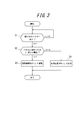
- FIG. 4 is a flowchart illustrating an operation of the electronic device according to the first embodiment. It is a figure which shows the functional block of the electronic device which concerns on Embodiment 2.
- FIG. It is a figure which shows an example of the relationship of the effective frequency band of the 1st piezoelectric element which concerns on Embodiment 2, and a 2nd piezoelectric element. It is a figure which shows the mounting structure of the electronic device which concerns on Embodiment 2.
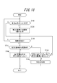
- FIG. 12 is a flowchart illustrating an example of an operation of the electronic device according to the second embodiment.
- FIG. 10 is a functional block diagram of an electronic device according to a fourth embodiment. It is a figure which shows an example of the mounting structure of the electronic device which concerns on Embodiment 4.
- FIG. 10 is a flowchart for explaining processing by the electronic apparatus according to the fourth embodiment.
- 14 is a flowchart for describing processing by the electronic apparatus according to the fifth embodiment.
- FIG. 10 is a functional block diagram of an electronic device according to a sixth embodiment. It is a figure which shows an example of the mounting structure of the electronic device which concerns on Embodiment 6.
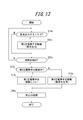
- FIG. 14 is a flowchart for describing processing by the electronic apparatus according to the sixth embodiment.
- 15 is a flowchart for describing processing by the electronic apparatus according to the seventh embodiment.
- FIG. 10 is a functional block diagram of an electronic device according to an eighth embodiment. It is a figure which shows an example of the mounting structure of the electronic device which concerns on Embodiment 8.
- FIG. 16 is a flowchart for describing processing by the electronic apparatus according to the eighth embodiment.
- 14 is a flowchart for describing processing by the electronic apparatus according to the ninth embodiment.
- FIG. 16 is a functional block diagram of an electronic device according to an eleventh embodiment. It is a figure which shows an example of the mounting structure of the electronic device which concerns on Embodiment 11.
- FIG. 18 is a flowchart for describing processing by the electronic apparatus according to the eleventh embodiment. 18 is a flowchart for describing processing by the electronic apparatus according to the twelfth embodiment.
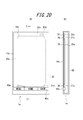
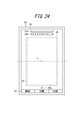
- FIG. 20 is a functional block diagram of an electronic device according to a thirteenth embodiment. It is a figure which shows an example of the mounting structure of the electronic device which concerns on Embodiment 13.
- FIG. 20 is a functional block diagram of an electronic device according to a thirteenth embodiment. It is a figure which shows an example of the mounting structure of the electronic device which concerns on Embodiment 13.
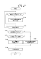
- 24 is a flowchart for describing processing by the electronic apparatus according to the thirteenth embodiment. 24 is a flowchart for describing processing by the electronic apparatus according to the fourteenth embodiment. It is a figure which shows an example of the vibration of the panel of the electronic device which concerns on this invention.
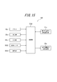
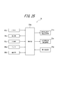
- FIG. 1 is a diagram showing functional blocks of an electronic device 1b according to an embodiment of the present invention.
- the electronic device 1b is, for example, a mobile phone (smart phone), and includes a panel 10, a display unit 20, a vibration unit 30, a detection unit 40, a control unit 50, and a communication unit 70.
- the vibration of the panel 10 generated by the vibration unit 30 generates a sound transmitted to the inside of the human body.
- the sound transmitted to the inside of the human body vibrates the middle ear or the inner ear via a soft tissue (for example, cartilage) of the human body.
- the panel 10 is a touch panel that detects contact, a cover panel that protects the display unit 20, or the like.
- the panel 10 is made of, for example, glass or a synthetic resin such as acrylic.
- the shape of the panel 10 may be a plate shape.
- the panel 10 may be a flat plate or a curved panel whose surface is smoothly inclined.
- a detection method of the touch panel any method such as a capacitance method, a resistance film method, a surface acoustic wave method (or an ultrasonic method), an infrared method, an electromagnetic induction method, and a load detection method can be used.
- the panel 10 is preferably rectangular.
- the display unit 20 is a display device such as a liquid crystal display, an organic EL display, or an inorganic EL display.
- the display unit 20 is provided on the back surface of the panel 10.
- the display unit 20 is disposed on the back surface of the panel 10 by a bonding member (for example, an adhesive).
- the display unit 20 may be disposed apart from the panel 10 and supported by the housing of the electronic device 1.
- the vibration unit 30 is an element that expands or contracts (bends) according to the electromechanical coupling coefficient of the constituent material by applying an electric signal (voltage).
- a piezoelectric element made of, for example, ceramic or quartz is used.
- the vibration unit 30 may be a unimorph, bimorph, or multilayer piezoelectric element.
- the stacked piezoelectric element includes a stacked unimorph element in which unimorphs are stacked (for example, 16 layers or 24 layers), or a stacked bimorph element in which bimorphs are stacked (for example, 16 layers or 24 layers are stacked).
- the laminated piezoelectric element is composed of a laminated structure of a plurality of dielectric layers made of, for example, PZT (lead zirconate titanate) and electrode layers arranged between the plurality of dielectric layers.
- a unimorph expands and contracts when an electric signal (voltage) is applied, and a bimorph bends when an electric signal (voltage) is applied.
- the vibration unit 30 is a piezoelectric element for transmitting sound.
- the vibration unit 30 is disposed on the back surface of the panel 10 by a joining member (for example, an adhesive).
- the detection unit 40 detects a pressure on the panel 10, for example, an element such as a strain gauge sensor or a piezoelectric element whose physical or electrical characteristics (strain, resistance, voltage, etc.) change according to the pressure. Use to configure.
- the piezoelectric element of the detection unit 40 has a magnitude (or load (force) of a load (force) related to pressing against the touch surface of the panel 10.
- the magnitude of the voltage (voltage value (hereinafter simply referred to as data)), which is an electrical characteristic, changes according to the speed (acceleration) at which the magnitude changes.
- the control unit 50 acquires the data when the detection unit 40 notifies the control unit 50 of the data, or when the control unit 50 detects data related to the piezoelectric element of the detection unit 40. That is, the control unit 50 acquires data based on the pressure on the touch surface of the panel 10 from the detection unit 40.
- the vibration unit 30 may be configured with a piezoelectric element and may also serve as the detection unit 40.
- the control unit 50 applies an electrical signal to the vibration unit 30, drives the vibration unit 30, and controls sound output.
- the voltage applied by the control unit 50 to the vibration unit 30 is, for example, ⁇ 15 V, which is higher than ⁇ 5 V, which is an applied voltage of a so-called panel speaker for the purpose of conducting sound by air conduction sound instead of vibration sound. It may be. Note that how much applied voltage is used can be appropriately adjusted according to the fixing strength of the panel 10 to the casing or the support member or the performance of the vibration unit 30.
- the control unit 50 drives the vibration unit 30 based on a sound output trigger from a predetermined application or the like (based on an audio signal or the like).
- control unit 50 changes the strength of vibration of the vibration unit 30 according to the force applied to the panel 10 detected by the detection unit 40. That is, when the force applied to panel 10 is equal to or greater than a predetermined threshold, control unit 50 increases the vibration of panel 10 more than when the force applied to panel 10 is less than the predetermined threshold. Specifically, the control unit 50 increases the voltage applied to the vibrating unit 30 when the force applied to the panel 10, that is, the data based on the pressure is greater than or equal to a predetermined threshold, than when the data is less than the predetermined threshold. For example, when the force applied to the panel 10 is equal to or greater than a predetermined threshold, the control unit 50 sets the vibration amplitude of the vibration unit 30 to A and vibrates the vibration unit 30.
- the control unit 50 sets the vibration amplitude of the vibration unit 30 to B (here, A> B) and vibrates the vibration unit 30.
- the predetermined threshold is 5N, or a data value (for example, 1V) based on a pressure detected (acquired) by the control unit 50 when 5N is added to the panel 10.
- the vibration unit 30 to which the electric signal is applied expands and contracts in the long side direction.
- the panel 10 to which the vibration unit 30 is attached is deformed according to the expansion and contraction of the vibration unit 30, and the panel 10 vibrates.
- the panel 10 is bent by the expansion / contraction or bending of the vibration unit 30.
- the panel 10 is bent directly by the vibration part 30.
- the panel 10 is bent directly by the vibration part means that the panel is specified by the inertial force of the piezoelectric actuator configured by arranging the vibration part in the casing as used in a conventional panel speaker. This is different from the phenomenon in which the panel is deformed by exciting the region.
- the panel 10 is directly bent by the vibrating part means that the expansion or contraction or bending (curving) of the vibrating part is that the panel is bent directly via the joining member or via the joining member and the reinforcing member described later. Means.
- the control unit 50 transmits the air conduction sound and the vibration sound to the object in contact with the panel 10.
- the control unit 50 can generate an air conduction sound and a vibration sound corresponding to the sound signal by applying an electric signal corresponding to the sound signal related to the voice of the other party to the vibration unit 30, for example.
- the audio signal may relate to a ringing melody or a music piece including music. Note that the audio signal applied to the electrical signal may be based on music data stored in the internal memory of the electronic device 1, or music data stored in an external server or the like is reproduced via a network. May be.
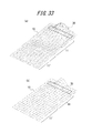
- the panel 10 vibrates not only in the attachment region to which the vibration unit 30 is attached, but also in the region away from the attachment region.
- the panel 10 has a plurality of locations that vibrate in a direction intersecting the main surface of the panel 10 in the vibrating region, and the amplitude value of the vibration is increased from positive to negative with time in each of the plurality of locations. Or vice versa.
- the panel 10 vibrates in such a manner that a portion having a relatively large vibration amplitude and a portion having a relatively small vibration amplitude are distributed randomly or periodically throughout the panel 10 at first glance. That is, vibrations of a plurality of waves are detected over the entire panel 10.
- the communication unit 70 is used to communicate with other electronic devices.
- the communication unit 70 allows the user of the electronic device 1 to make a call with a user such as another electronic device.
- a microphone (not shown) collects the voice spoken by the user of the electronic device 1. Further, the panel 10 vibrates and outputs a voice spoken by a user such as another electronic device.
- FIG. 2 is a diagram showing a mounting structure of electronic device 1 according to the present embodiment.
- the electronic device 1 shown in FIG. 2 is a smartphone in which a touch panel, which is a glass plate, is arranged as a panel 10 on the front surface of a housing 60 (for example, a metal or resin case).
- the panel 10 is supported by the housing 60, and the display unit 20 and the vibration unit 30 are bonded to the panel 10 with bonding members.
- the joining member is an adhesive having a thermosetting property or an ultraviolet curable property, a double-sided tape, or the like, and may be, for example, an optical elastic resin which is a colorless and transparent acrylic ultraviolet curable adhesive.
- the panel 10, the display unit 20, and the vibration unit 30 are each rectangular, but are not limited thereto.
- the display unit 20 is disposed approximately at the center of the panel 10 in the short direction.
- the vibration unit 30 is arranged at a predetermined distance from the end of the panel 10 in the longitudinal direction, and is arranged in the vicinity of the end so that the long side direction of the vibration unit 30 is along the short side of the panel 10.
- the display unit 20 and the vibration unit 30 are arranged side by side in a direction parallel to the inner surface of the panel 10.
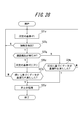
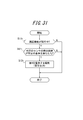
- control unit 50 detects whether there is a sound output trigger from a predetermined application or the like (step S1). If there is a sound output trigger, the process proceeds to step S2. If there is no sound output trigger, step S1 is repeated.
- control unit 50 determines whether the force applied to the panel 10 detected by the detection unit 40 is equal to or greater than a predetermined threshold (step S2). If it is equal to or greater than the predetermined threshold value, the process proceeds to step S3. If it is less than the predetermined threshold, the process proceeds to step S4.
- the control unit 50 sets the vibration amplitude of the vibration unit 30 to A and vibrates the vibration unit 30 (step S3). Then, the process ends.
- the control unit 50 sets the vibration amplitude of the vibration unit 30 to B and vibrates the vibration unit 30 (step S4). Then, the process ends.
- the vibration strength of the vibration unit 30 is changed according to the force applied to the panel 10. Sound can be transmitted effectively.
- the electronic device 1 can transmit air conduction sound and vibration sound transmitted through a part of the user's body (for example, cartilage of the outer ear) to the user by the vibration of the panel 10. Therefore, when outputting a sound having a volume equivalent to that of a conventional dynamic receiver, the sound transmitted to the periphery of the electronic device 1 due to the vibration of the air due to the vibration of the panel 10 is less than that of the dynamic receiver. Therefore, it is suitable, for example, when listening to a recorded message on a train or the like.
- the electronic device 1 transmits vibration sound due to the vibration of the panel 10, even if the user wears an earphone or a headphone, for example, the user can touch the electronic device 1 to contact the earphone or the headphone. Sounds can be heard through headphones and body parts.
- the electronic device 1 transmits sound to the user by the vibration of the panel 10. Therefore, when the electronic device 1 does not include a separate dynamic receiver, it is not necessary to form an opening (sound emission port) for sound transmission in the housing 60, and the waterproof structure of the electronic device 1 can be simplified.
- the sound emission port is preferably closed by a member that allows gas to pass but not liquid.
- a member that allows gas to pass but not liquid is Gore-Tex (registered trademark).
- the intensity of vibration corresponding to the force applied to the panel 10 is changed in two stages based on a predetermined threshold value.
- the present invention is not limited to this, and a plurality of threshold values may be provided to be multistage. . Further, the intensity of vibration may be continuously changed according to the force applied to the panel 10.
- FIG. 4 is a diagram showing functional blocks of the electronic device 1b according to Embodiment 2 of the present invention.
- the electronic device 1b is, for example, a mobile phone (smart phone), and includes a panel 10, a display unit 20, a first piezoelectric element 31b, a second piezoelectric element 32b, an input unit 40b, and a control unit 50b.
- the vibration of the panel 10 generated by the first piezoelectric element 32b and the second piezoelectric element 32b generates a sound transmitted to the inside of the human body.
- the sound transmitted to the inside of the human body vibrates the middle ear or the inner ear via a soft tissue (for example, cartilage) of the human body.
- the first piezoelectric element 31b is an element that expands or contracts (bends) according to the electromechanical coupling coefficient of the constituent material by applying an electric signal (voltage).
- the first piezoelectric element 31b may be a unimorph, bimorph, or multilayer piezoelectric element.
- the stacked piezoelectric element includes a stacked unimorph element in which unimorphs are stacked (for example, 16 layers or 24 layers), or a stacked bimorph element in which bimorphs are stacked (for example, 16 layers or 24 layers are stacked).
- the laminated piezoelectric element is composed of a laminated structure of a plurality of dielectric layers made of, for example, PZT (lead zirconate titanate) and electrode layers arranged between the plurality of dielectric layers.
- a unimorph expands and contracts when an electric signal (voltage) is applied, and a bimorph bends when an electric signal (voltage) is applied.
- the first piezoelectric element 31 b is a piezoelectric element for presenting a tactile sensation to a contact object in contact with the panel 10.
- the first piezoelectric element 31b is preferably rectangular and expands and contracts in the direction of the long side.
- the first piezoelectric element 31b is disposed on the back surface of the panel 10 by a bonding member (for example, an adhesive).
- the second piezoelectric element 32b is an element that expands or contracts (bends) according to the electromechanical coupling coefficient of the constituent material by applying an electric signal (voltage).
- the second piezoelectric element 32b may be a unimorph, bimorph, or multilayer piezoelectric element.
- the stacked piezoelectric element includes a stacked unimorph element in which unimorphs are stacked (for example, 16 layers or 24 layers), or a stacked bimorph element in which bimorphs are stacked (for example, 16 layers or 24 layers are stacked).
- the laminated piezoelectric element is composed of a laminated structure of a plurality of dielectric layers made of, for example, PZT (lead zirconate titanate) and electrode layers arranged between the plurality of dielectric layers.
- a unimorph expands and contracts when an electric signal (voltage) is applied, and a bimorph bends when an electric signal (voltage) is applied.
- the second piezoelectric element 32b is a piezoelectric element for transmitting sound.
- the second piezoelectric element 32b is preferably rectangular and expands and contracts in the direction of the long side.
- the second piezoelectric element 32b is disposed on the back surface of the panel 10 by a bonding member (for example, an adhesive).
- the input unit 40b detects an operation input by the user, and includes, for example, an operation button (operation key).
- an operation button operation key
- the panel 10 can also detect an operation by the user by detecting a contact by the user.
- the control unit 50b is a processor that controls the electronic device 1b.
- the controller 50b applies a predetermined electrical signal to the first piezoelectric element 31b and the second piezoelectric element 32b.
- the controller 50b applies an electrical signal to the first piezoelectric element 31b to drive the first piezoelectric element 31b.
- the electronic device 1b may include a pressure detection unit (not shown) that detects a pressure on the panel 10. Good. And if the data based on the press with respect to the panel 10 satisfy
- the pressure detection unit detects the pressure on the panel 10 and, for example, an element such as a strain gauge sensor or a piezoelectric element whose physical or electrical characteristics (strain, resistance, voltage, etc.) change according to the pressure, etc. To configure.
- the piezoelectric element of the pressure detection unit has a load (force) magnitude (or load (force)) related to the pressure on the touch surface of the panel 10.
- the magnitude of the voltage (voltage value (hereinafter simply referred to as data)), which is an electrical characteristic, changes according to the speed (acceleration) at which the magnitude changes.
- the control unit 50b acquires the data when the press detection unit notifies the control unit 50b of the data, or when the control unit 50b detects data related to the piezoelectric element of the press detection unit. That is, the control unit 50b acquires data based on the pressure on the touch surface of the panel 10 from the pressure detection unit.
- the press detection unit is configured by a piezoelectric element
- the first piezoelectric element 31b may also serve as the press detection unit.
- the controller 50b applies an electrical signal to the second piezoelectric element 32b, drives the second piezoelectric element 32b, and controls sound output.
- the voltage applied to the second piezoelectric element 32b by the control unit 50b is higher than ⁇ 5V, which is an applied voltage of a so-called panel speaker for the purpose of conducting sound by air conduction sound instead of vibration sound, for example, ⁇ It may be 15V.
- ⁇ 5V is an applied voltage of a so-called panel speaker for the purpose of conducting sound by air conduction sound instead of vibration sound, for example, ⁇ It may be 15V.
- the control unit 50b drives the second piezoelectric element 32b based on a sound output trigger from a predetermined application or the like (based on an audio signal (sound signal) or the like).
- the controller 50b controls to drive the first piezoelectric element 31b in addition to the second piezoelectric element 32b when outputting sound.
- the control unit 50b includes a signal combiner 51 (combiner).
- the signal combiner 51 combines the control signal related to the tactile sensation and the control signal related to the sound output, and supplies the combined signal to the first piezoelectric element 31b.
- the signal combiner 51 of the control unit 50b combines the control signal related to the tactile sensation and the control signal related to the sound output, the tactile sensation presenting function of the first piezoelectric element 31b is not disturbed.
- the first piezoelectric element 31b is a piezoelectric element for presenting a tactile sensation to the contact object in contact with the panel 10 as described above.
- the piezoelectric element for presenting a tactile sensation is larger in size than the piezoelectric element for transmitting sound. That is, preferably, the first piezoelectric element 31b is larger than the second piezoelectric element 32b, so that the resonance frequency of the first piezoelectric element 31b is lower than the resonance frequency of the second piezoelectric element 32b.
- the first piezoelectric element 31b transmits a low sound and the second piezoelectric element 32b transmits a high sound.
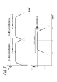
- FIG. 5 is a diagram showing a relationship between effective frequency bands of the first piezoelectric element 31b and the second piezoelectric element 32b in the second embodiment.
- the effective frequency band of the piezoelectric element is a frequency band in which the piezoelectric element can emit an audibly effective sound.
- the effective frequency band of the piezoelectric element is a frequency band having an amplitude that is 1/2 or more of the maximum amplitude with reference to the amplitude (maximum amplitude) at the resonance frequency of the piezoelectric element.
- FIG. 5B is a conceptual diagram relating to the resonance frequency and effective frequency band of a certain piezoelectric element. In FIG. 5B, the resonance frequency is Fx, and the effective frequency band is Fy to Fz.
- the amplitude at Fx is Ax.
- the amplitude at a certain frequency Fy (Fy ⁇ Fx) is Ay
- the amplitude at a certain frequency Fz (Fx ⁇ Fz) is Az.
- Ay and Az are 1/2 of Ax
- the amplitudes in Fy to Fz are 1/2 or more of Ax.
- the effective frequency band may be a frequency band having an amplitude of 1/3 or more of the maximum amplitude, and can be appropriately set depending on the product to be used. Further, the effective frequency band may be a 3 dB bandwidth centered on the resonance frequency.
- the resonance frequency and effective frequency band of the piezoelectric element may be those in a vibration system in which the piezoelectric element is mounted on the touch panel.
- the effective frequency band of the first piezoelectric element 31b and the effective frequency band of the second piezoelectric element 32b do not overlap.
- the effective frequency band of the first piezoelectric element 31b is 1 Hz or more and less than 400 Hz
- the effective frequency band of the second piezoelectric element 32b is 400 Hz or more and less than 20000 Hz.
- the controller 50b outputs sound
- the sound included in the effective frequency band of the first piezoelectric element 31b is output by the first piezoelectric element 31b and included in the effective frequency band of the second piezoelectric element 32b.
- the 1st piezoelectric element 31b and the 2nd piezoelectric element 32b complement each other.
- the control unit 50b applies an electrical signal to the first piezoelectric element 31b and the second piezoelectric element 32b
- the first piezoelectric element 31b and the second piezoelectric element 32b to which the electrical signal is applied expands and contracts in the long side direction.
- the panel 10 to which the first piezoelectric element 31b and the second piezoelectric element 32b are attached is deformed according to the expansion and contraction of the first piezoelectric element 31b and the second piezoelectric element 32b, and the panel 10 vibrates.
- the panel 10 is bent by expansion / contraction or bending of the first piezoelectric element 31b and the second piezoelectric element 32b.
- the panel 10 is bent directly by the first piezoelectric element 31b and the second piezoelectric element 32b.
- the panel 10 is directly bent by a piezoelectric element means that the panel is specified by the inertial force of a piezoelectric actuator configured by arranging a vibration part in a casing, as used in a conventional panel speaker. This is different from the phenomenon in which the panel is deformed by exciting the region.
- the panel 10 is directly bent by the piezoelectric element means that the expansion and contraction or bending (curving) of the piezoelectric element bends the panel directly via the bonding member or via the bonding member and the reinforcing member described later. Means.
- the control unit 50b transmits the air conduction sound and the vibration sound to the object in contact with the panel 10.
- the control unit 50b can apply an electrical signal corresponding to a voice signal related to the voice of the other party to the second piezoelectric element 32b, for example, and generate air conduction sound and vibration sound corresponding to the voice signal.
- the audio signal may relate to a ringing melody or a music piece including music.
- the audio signal applied to the electrical signal may be based on music data stored in the internal memory of the electronic device 1b, or music data stored in an external server or the like may be reproduced via a network. May be.
- the panel 10 vibrates not only in the attachment region where the first piezoelectric element 31b and the second piezoelectric element 32b are attached, but also in the region away from the attachment region.
- the panel 10 has a plurality of locations that vibrate in a direction intersecting the main surface of the panel 10 in the vibrating region, and the amplitude value of the vibration is increased from positive to negative with time in each of the plurality of locations. Or vice versa.
- the panel 10 vibrates in such a manner that a portion having a relatively large vibration amplitude and a portion having a relatively small vibration amplitude are distributed randomly or periodically throughout the panel 10 at first glance. That is, vibrations of a plurality of waves are detected over the entire panel 10.
- the control unit 50b applies the second piezoelectric element 32b to prevent the above-described vibration of the panel 10 from being attenuated.
- the applied voltage may be ⁇ 15V. Therefore, the user can hear the sound by bringing his / her ear into contact with a region away from the above-described region where the panel 10 is attached.
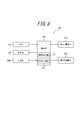
- FIG. 6 is a diagram showing a mounting structure of electronic device 2b according to the present embodiment.
- An electronic device 1b illustrated in FIG. 6 is a smartphone in which a touch panel, which is a glass plate, is arranged as a panel 10 on the front surface of a housing 60 (for example, a metal or resin case).
- the panel 10 and the input unit 40b are supported by the housing 60, and the display unit 20, the first piezoelectric element 31b, and the second piezoelectric element 32b are bonded to the panel 10 with bonding members, respectively.
- the joining member is an adhesive having a thermosetting property or an ultraviolet curable property, a double-sided tape, or the like, and may be, for example, an optical elastic resin which is a colorless and transparent acrylic ultraviolet curable adhesive.
- the panel 10, the display unit 20, the first piezoelectric element 31b, and the second piezoelectric element 32b are each rectangular.
- the display unit 20 is disposed approximately at the center of the panel 10 in the short direction.
- the first piezoelectric element 31b is separated from the end in the longitudinal direction of the panel 10 by a predetermined distance, and the long side direction of the first piezoelectric element 31b is along the short side of the panel 10 in the vicinity of the end. Be placed.
- the display unit 20 and the first piezoelectric element 31 b are arranged side by side in a direction parallel to the inner surface of the panel 10.
- the second piezoelectric element 32b is separated from the end in the longitudinal direction of the panel 10 by a predetermined distance, and the long side direction of the second piezoelectric element 32b is along the short side of the panel 10 in the vicinity of the end.
- the position where the first piezoelectric element 31b and the second piezoelectric element 32b are arranged is an example, and is not limited thereto.
- the long side direction of the second piezoelectric element 32 b may be arranged along the long side of the panel 10.
- the 2nd piezoelectric element 32b may be arrange
- the first piezoelectric element 31b and the second piezoelectric element 32b are preferable because they do not act in the direction of preventing vibration from each other.
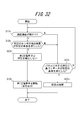
- control unit 50b detects whether or not there is a trigger for sound output from a predetermined application or the like (step S11). If there is a sound output trigger, the process proceeds to step S12. If there is no sound output trigger, step S11 is repeated.
- step S12 When there is a sound output trigger, when the controller 50b outputs a sound, the sound included in the effective frequency band of the first piezoelectric element 31b is output by the first piezoelectric element 31b, and the second piezoelectric element 32b The sound included in the effective frequency band is output by the second piezoelectric element 32b (step S12). Then, the process ends.
- the electronic apparatus 1b when outputting sound, the sound included in the effective frequency band of the first piezoelectric element 31b is output by the first piezoelectric element 31b, and the second piezoelectric element 31b is output.
- the sound included in the effective frequency band of the element 32b is output by the second piezoelectric element 32b. Therefore, when the piezoelectric element for the tactile sensation presentation function and the piezoelectric element for the conduction function such as the air conduction sound are disposed, the first piezoelectric element 31b and the second piezoelectric element 32b compensate for the effective frequency band, and the sound Is output, so that the acoustic effect can be improved.
- the electronic device 1b described above can transmit air conduction sound and vibration sound transmitted through a part of the user's body (for example, cartilage of the outer ear) to the user by the vibration of the panel 10. Therefore, when outputting a sound having a volume equivalent to that of a conventional dynamic receiver, the sound transmitted to the surroundings of the electronic device 1b due to the vibration of air due to the vibration of the panel 10 is less than that of the dynamic receiver. Therefore, it is suitable, for example, when listening to a recorded message on a train or the like.
- the electronic device 1b transmits vibration sound by the vibration of the panel 10, even if the user wears an earphone or a headphone, for example, by bringing the electronic device 1b into contact with the user, Sounds can be heard through headphones and body parts.
- the electronic device 1b transmits sound to the user by the vibration of the panel 10. Therefore, when the electronic device 1b does not include a separate dynamic receiver, it is not necessary to form an opening (sound outlet) for sound transmission in the housing 60, and the waterproof structure of the electronic device 1b can be simplified.
- the sound emission port is preferably closed by a member that allows gas to pass but not liquid.
- a member that allows gas to pass but not liquid is Gore-Tex (registered trademark).
- the third embodiment of the present invention will be described below.
- symbol is attached
- the electronic device 2b of the second embodiment is different from the electronic device 1b of the first embodiment in that the relationship between the effective frequency bands of the first piezoelectric element 31b and the second piezoelectric element 32b is different. Specifically, the effective frequency band of the first piezoelectric element 31b and the effective frequency band of the second piezoelectric element 32b are different.
- FIG. 8 is a diagram showing functional blocks of the electronic device 2b according to Embodiment 3 of the present invention.
- the electronic device 2b according to the second embodiment is different from the electronic device 1b according to the first embodiment in that the control unit 50b includes a band separator 52 in addition to the configuration of the electronic device 1b according to the first embodiment.
- the band separator 52 separates the frequency band so that the combined frequency characteristics are flat. Specifically, the volume of the frequency region where the effective frequency band of the first piezoelectric element 31b and the effective frequency band of the second piezoelectric element 32b overlap is extremely large compared to the volume of other frequency regions. Accordingly, the band separator 52 separates the signal related to the output sound based on the frequency band so that the volume of the overlapping frequency region does not deviate too much from the volume of the non-overlapping portion, and the first and second piezoelectric elements 31b and 2 The separated signal is passed to the piezoelectric element 32b.
- the band separator 52 does not separate the signal related to the sound to be output, and the volume in the frequency region where the effective frequency band of the first piezoelectric element 31b and the effective frequency band of the second piezoelectric element 32b overlap. That is, it is effective to make the bass sound louder than the sound volume in other frequency regions.
- FIG. 9 is a diagram showing a relationship between effective frequency bands of the first piezoelectric element 31b and the second piezoelectric element 32b according to the second embodiment.
- the effective frequency band of the first piezoelectric element 31b and the effective frequency band of the second piezoelectric element 32b overlap.
- the effective frequency band of the first piezoelectric element 31b is 1 Hz or more and less than 400 Hz
- the effective frequency band of the second piezoelectric element 32b is 200 Hz or more and less than 20000 Hz.
- the control unit 50b controls to drive the first piezoelectric element 31b in addition to the second piezoelectric element 32b.
- the control unit 50b drives the second piezoelectric element 32b without driving the first piezoelectric element 31b.
- Whether the bass is emphasized is determined by the input unit 40b detecting an operation input by the user.
- the input unit 40b makes a setting for emphasizing bass (hereinafter referred to as bass emphasis setting) or cancels the bass emphasis setting based on an operation input by the user.
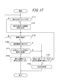
- step S11 determines whether or not the electronic apparatus 2b is set to emphasize bass (step S22). If the bass enhancement setting is selected, the process proceeds to step S23. If it is not the bass enhancement setting, the process proceeds to step S24.
- control unit 50b controls the sound to be output so as to drive the first piezoelectric element 31b in addition to the second piezoelectric element 32b (step S23). Then, the process ends.
- controller 50b drives the second piezoelectric element 32b without driving the first piezoelectric element 31b when not emphasizing the bass (step S24). Then, the process ends.
- the electronic device 2b when emphasizing the bass sound, in addition to the second piezoelectric element 32b, control is performed so as to drive the first piezoelectric element 31b.
- the acoustic effect can be improved.
- the bass emphasis setting is switched depending on whether the first piezoelectric element 31b and the second piezoelectric element 32b are used or only the second piezoelectric element 32b is used.
- the present invention is not limited to this.
- the intensity of vibration of the first piezoelectric element 31b may be changed in addition to the second piezoelectric element 32b in accordance with the degree of bass emphasis.
- the band separated by the band separator 52 may be changed according to the degree of bass emphasis.
- Embodiment 4 an embodiment of an electronic apparatus according to Embodiment 4 of the present invention will be described with reference to the drawings.
- symbol is attached
- the electronic device according to the present invention can be a mobile phone, a smartphone, a tablet PC, or the like provided with a touch panel.
- the present invention is not limited to these portable devices, and can be various electronic devices such as home appliances, industrial devices (FA devices), and dedicated terminals provided with a touch panel.
- FA devices industrial devices
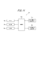
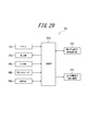
- FIG. 11 is a functional block diagram of an electronic device according to Embodiment 4 of the present invention.
- an electronic apparatus 1c according to Embodiment 4 of the present invention includes a panel 10c, a display unit 20c, a first piezoelectric element 31c, a second piezoelectric element 32c, an input unit 40c, and a control unit 50c. Yes.
- the vibration of the panel 10c generated by the second piezoelectric element 32c generates a sound transmitted to the inside of the human body.
- the sound transmitted to the inside of the human body vibrates the middle ear or the inner ear via a soft tissue (for example, cartilage) of the human body.
- the panel 10c can be a touch panel for detecting contact, a cover panel for protecting the display unit 20c, or the like.
- the panel 10c is preferably formed of a synthetic resin such as glass or acrylic.
- the panel 10c is formed of a synthetic resin such as glass or acrylic.
- the shape of the panel 10c may be a plate shape.
- the panel 10c may be a flat plate, or may be a curved panel whose surface is smoothly inclined. When the panel 10c is a touch panel, it detects contact of a user's finger or stylus pen.
- the detection method of the touch panel should be an arbitrary method such as a capacitance method, a resistance film method, an optical method, a surface acoustic wave method (or an ultrasonic method), an infrared method, an electromagnetic induction method, and a load detection method. Can do.
- the panel 10c is arranged in a housing or the like so as to be able to vibrate by an appropriate means. That is, if all the edges of the panel 10c are firmly fixed to the housing or the like, the amplitude when the panel 10c is vibrated cannot be obtained, and a good tactile sensation cannot be presented to the user. Therefore, for example, the panel 10c is disposed in the housing via an elastic member, or the panel 10c is partially fixed to the housing, so that the panel 10c can be vibrated and disposed in the housing. It is preferable to install them.
- the panel 10c When the panel 10c is configured by a member such as a touch panel, the panel 10c detects contact with a touch surface such as a user's finger or stylus pen, and outputs information on the position of the contact. With this output, the control unit 50c can acquire the position of the contact detected by the panel 10c.
- the display unit 20c is a display device such as a liquid crystal display, an organic EL display, or an inorganic EL display.
- the display unit 20c can display various information, images, and objects such as keys and buttons on the screen.
- the display unit 20c is provided on the back surface of the panel 10c.
- the display part 20c is arrange
- the display unit 20c may be disposed apart from the panel 10c and supported by the casing of the electronic device 1c.
- the panel 10c is configured with a member such as a touch panel, it is preferable that the panel 10c is configured with, for example, a transparent member and the display unit 20c is disposed on the back side thereof.
- an object such as a key or a button can be drawn and displayed on the display unit 20c, and an operation of the user pressing the object can be detected on the panel 10c.
- Such display of the display unit 20c can be performed by control by the control unit 50c.
- the first piezoelectric element 31c and the second piezoelectric element 32c are elements that expand or contract (bend) according to the electromechanical coupling coefficient of the constituent material by applying an electric signal (voltage). These piezoelectric elements are made of, for example, ceramic or quartz.
- the first piezoelectric element 31c and the second piezoelectric element 32c can be unimorphs, bimorphs, or stacked piezoelectric elements.
- the stacked piezoelectric element includes a stacked unimorph element in which unimorphs are stacked (for example, 16 layers or 24 layers), or a stacked bimorph element in which bimorphs are stacked (for example, 16 layers or 24 layers are stacked).
- the laminated piezoelectric element is composed of a laminated structure of a plurality of dielectric layers made of, for example, PZT (lead zirconate titanate) and electrode layers arranged between the plurality of dielectric layers.
- PZT lead zirconate titanate
- a unimorph expands and contracts when an electric signal (voltage) is applied, and a bimorph bends when an electric signal (voltage) is applied.
- the first piezoelectric element 31c and the second piezoelectric element 32c are preferably arranged on the back surface of the panel 10c (the surface on the inner side of the electronic device 1c).
- the first piezoelectric element 31c and the second piezoelectric element 32c are attached to the panel 10c by a joining member (for example, double-sided tape).
- the first piezoelectric element 31c and the second piezoelectric element 32c may be attached to the panel 10c via an intermediate member (for example, a sheet metal).
- the first piezoelectric element 31c and the second piezoelectric element 32c are arranged on the back surface of the panel 10c and are separated from the inner surface of the housing by a predetermined distance.
- the first piezoelectric element 31c and the second piezoelectric element 32c be separated from the surface on the inner side of the housing by a predetermined distance even in a stretched or bent state. That is, the distance between the first piezoelectric element 31c and the second piezoelectric element 32c and the inner surface of the housing is set to be larger than the maximum deformation amount of the first piezoelectric element 31c and the second piezoelectric element 32c. Is preferred.
- the first piezoelectric element 31c is a piezoelectric element mainly used for presenting a tactile sensation. Therefore, it is desirable that the first piezoelectric element 31c be designed so as to have a frequency characteristic suitable for presenting a predetermined tactile sensation based on an electrical signal from the control unit 50c.
- the second piezoelectric element 32c is a piezoelectric element mainly used for transmitting sound. Therefore, it is desirable to employ the second piezoelectric element 32c designed to have a frequency characteristic suitable for transmitting a predetermined sound based on the electric signal from the control unit 50c.
- the first piezoelectric element and the second piezoelectric element are disposed on the panel 10c as different piezoelectric elements.
- the input unit 40c detects a user's input operation and includes, for example, operation buttons (operation keys).
- the user input operation detected by the input unit 40c is sent to the control unit 50c as an electrical signal.
- the panel 10c is a touch panel, the panel 10c can also detect the contact from a user.
- the control unit 50c is a processor that controls the electronic device 1c.
- the controller 50c applies a predetermined electrical signal to the first piezoelectric element 31c and the second piezoelectric element 32c.
- the control unit 50c applies an electrical signal to the first piezoelectric element 31c to drive the first piezoelectric element 31c.
- the controller 50c applies an electrical signal to the second piezoelectric element 32c, drives the second piezoelectric element 32c, and controls sound output.
- the control unit 50c is based on a sound output trigger from a predetermined application or the like (based on a sound signal (sound signal) or the like). It can be controlled to drive the second piezoelectric element 32c.
- the voltage applied to the second piezoelectric element 32c by the control unit 50c is higher than ⁇ 5 V, which is an applied voltage of a so-called panel speaker for the purpose of conducting sound by air conduction sound instead of vibration sound, for example. , ⁇ 15V.
- ⁇ 5 V is an applied voltage of a so-called panel speaker for the purpose of conducting sound by air conduction sound instead of vibration sound, for example. , ⁇ 15V.
- the controller 50c applies an electrical signal to the first piezoelectric element 31c and the second piezoelectric element 32c
- the first piezoelectric element 31c and the second piezoelectric element 32c to which the electrical signal is applied expands and contracts in the long side direction of each element.
- the panel 10c to which the first piezoelectric element 31c and the second piezoelectric element 32c are attached is deformed according to the expansion and contraction of the first piezoelectric element 31c and the second piezoelectric element 32c, and the panel 10c vibrates.
- the panel 10c is curved by expansion / contraction or bending of the first piezoelectric element 31c and the second piezoelectric element 32c.
- the panel 10c is bent directly by the first piezoelectric element 31c and the second piezoelectric element 32c.
- the panel 10c is directly bent by the piezoelectric element means that the panel is specified by the inertial force of the piezoelectric actuator configured by arranging the piezoelectric element in the casing as used in a conventional panel speaker. This is different from the phenomenon in which the panel is deformed by exciting the region.
- the panel 10c is directly bent by the piezoelectric element means that the expansion or contraction (bending) of the piezoelectric element bends the panel directly via the bonding member or via the bonding member and the reinforcing member described later. Means.
- the panel 10c When the second piezoelectric element 32c expands and contracts and the panel 10c vibrates, the panel 10c generates air conduction sound, and when the user touches a part of the body (for example, cartilage of the outer ear), A vibration sound transmitted through a part is generated. Then, the control unit 50c transmits the air conduction sound and the vibration sound to the object in contact with the panel 10c.
- the control unit 50c can apply an electric signal corresponding to a voice signal related to the voice of the other party to the second piezoelectric element 32c, for example, and generate air conduction sound and vibration sound corresponding to the voice signal.
- the audio signal may relate to a ringing melody or a music piece including music. Note that the audio signal applied to the electrical signal may be based on music data stored in the internal memory of the electronic device 1c, or music data stored in an external server or the like is reproduced via a network. May be.
- the panel 10c vibrates not only in the attachment region where the second piezoelectric element 32c is attached, but also in the region away from the attachment region.
- the panel 10c has a plurality of locations that vibrate in a direction intersecting with the main surface of the panel 10c in a region where the vibration is generated, and the amplitude value of the vibration at each of the plurality of locations increases from plus to minus with time. And vice versa.
- the panel 10c vibrates in such a manner that a portion having a relatively large vibration amplitude and a portion having a relatively small vibration amplitude are distributed randomly or periodically over the entire panel 10c. That is, vibrations of a plurality of waves are detected over the entire area of the panel 10c.
- the control unit 50c applies the second piezoelectric element 32c to suppress the above-described vibration attenuation of the panel 10c.
- the applied voltage may be ⁇ 15V. Therefore, the user can listen to the sound by bringing his / her ear into contact with an area away from the above-described attachment area of the panel 10c.
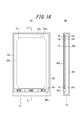
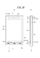
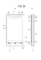
- FIG. 12 is a diagram illustrating an example of a mounting structure of the electronic device 1c according to the first embodiment. 12A is a front view, and FIG. 2B is a cross-sectional view taken along the line CC in FIG. 2A.
- the electronic device 1c shown in FIG. 12 is a smartphone in which a touch panel that is a glass plate is arranged on the front surface of a housing 60 (for example, a metal or resin case) as the panel 10c.
- the panel 10c and the input unit 40c are supported by the housing 60.
- the display unit 20c, the first piezoelectric element 31c, and the second piezoelectric element 32c are bonded to the panel 10c via the bonding member 70, respectively.
- the first piezoelectric element 31c and the second piezoelectric element 32c are bonded to the back side of the panel. In order to show this, in FIG.
- the joining member 70 is an adhesive having a thermosetting property or an ultraviolet curable property, a double-sided tape, or the like, and may be, for example, an optical elastic resin that is a colorless and transparent acrylic ultraviolet curable adhesive.
- the panel 10c, the display unit 20c, the first piezoelectric element 31c, and the second piezoelectric element 32c are each substantially rectangular.
- the display unit 20c is disposed substantially at the center in the short direction of the panel 10c. Further, the first piezoelectric element 31c and the second piezoelectric element 32c are separated from the end in the longitudinal direction of the panel 10c by a predetermined distance, and in the vicinity of the end, the first piezoelectric element 31c and the second piezoelectric element 32c. Are arranged such that the longitudinal direction of the panel extends along the short side of the panel 10c.
- the display unit 20c, the first piezoelectric element 31c, and the second piezoelectric element 32c are arranged side by side in a direction parallel to the surface on the back side of the panel 10c.
- the arrangement is not limited to the illustrated example.
- at least one of the first piezoelectric element 31c and the second piezoelectric element 32c can be arranged in parallel to the longitudinal direction of the electronic apparatus 1c (the longitudinal direction in FIG. 12A).
- the first piezoelectric element 31c and the second piezoelectric element 32c can be arbitrarily configured so as to be able to transmit vibration to the panel 10c by being attached to the panel 10c.
- the display unit 20 c is configured to be bonded to the back side of the panel 10 c via the bonding member 70, but the arrangement of the display unit 20 c is not limited to the illustrated example.
- the display unit 20c can be adhered to the back surface side of the panel 10c without the joining member 70, or can be disposed inside the housing 60 instead of being adhered to the panel 10c.
- the display unit 20 c is arranged inside the housing 60, the display unit 20 c is arranged and fixed directly inside the housing 60, or for a substrate or display unit arranged inside the housing 60. It can be fixed to a holder or the like. As shown in FIG.
- the electronic device 1c can include, for example, the control unit 50c and various elements such as various boards or components other than those shown in FIG.
- an area on the panel 10c where the display by the display unit 20c does not need to be transmitted is an area near the edge of the panel 10c. It is preferred to paint or cover with a bezel. In this way, it is possible to prevent the first piezoelectric element 31c, the second piezoelectric element 32c, and the like from being visible from the outside of the electronic device 1c.
- the control unit 50c performs control so as to output sound by driving the second piezoelectric element 32c.
- the 2nd piezoelectric element can implement
- the control unit 50c controls the first piezoelectric element 31c to be driven when the panel 10c detects contact.
- the 1st piezoelectric element can implement
- the piezoelectric element for presenting tactile sensation is driven when the sound transmitting piezoelectric element is vibrated to output sound. If vibration is generated, there is a risk of interference due to vibration of both piezoelectric elements. Therefore, in the present embodiment, processing as described below is performed under the control of the control unit 50c.
- FIG. 13 is a flowchart for explaining processing by the control unit 50c of the electronic device 1c according to the fourth embodiment.
- the control unit 50c determines whether or not a trigger for outputting a sound has occurred (step S11c).
- the trigger for outputting a sound is assumed to be various instructions such as an instruction to sound a ring tone by a call application when a call is received, or an instruction to play music by a music player application, for example. can do.
- the trigger for outputting sound is an arbitrary instruction that causes the panel 10c to vibrate and output sound by driving the second piezoelectric element 32c for sound output in the electronic device 1c. be able to.
- control unit 50c controls to output sound by driving the second piezoelectric element 32c (step S12c).
- step S12c the control unit 50c determines whether or not the panel 10c detects contact with a user's finger or ear (step S13c). In addition, when the trigger which outputs a sound has not generate
- step S13c When the panel 10c does not detect contact in step S13c, the control unit 50c returns to step S11c and continues the process. On the other hand, when the panel 10c detects contact in Step S13c, the control unit 50c determines whether or not the second piezoelectric element is being driven (Step S14c).
- step S14c If it is determined in step S14c that the second piezoelectric element is not being driven, there is no problem of interference even if vibration for presenting a tactile sensation is generated at this point, and therefore the control unit 50c causes the first piezoelectric element 31c to move. It controls to drive and to show a tactile sensation (step S15c). That is, when the panel 10c is touched in step S13c and no sound is output in step S14c, a tactile sensation is presented based on the touch. Therefore, the user can confirm by tactile sensation that the user's operation touching the panel 10c is correctly detected by the electronic device 1c.
- the control unit 50c performs control based on the position of the contact detected in step S13c so as to perform a predetermined process associated with the position.
- the predetermined processing is, for example, when the position of the contact detected on the panel 10c in step S13c corresponds to the position where the icon for starting the phone book application is displayed on the display unit 20c. It can be set as the process which starts.
- the predetermined process refers to the case where the position of the contact detected on the panel 10c in step S13c corresponds to the position where the character key is displayed on the display unit 20c, and the character key is displayed on the display unit 20c. The process can be displayed.
- the control unit 50c performs the present processing without performing predetermined processing in step S16c. It is preferable to end the processing of the embodiment.
- the case where no processing is associated with the detected contact position means, for example, that the contact position detected in the panel 10c in step S13c is an object such as any icon or key on the display unit 20c. The case where it corresponds to the position which is not displayed also can be assumed.
- step S14c determines whether the second piezoelectric element is being driven (the control unit 50c is driving the second piezoelectric element)
- the control unit 50c performs control so as not to drive the first piezoelectric element 31c (step S17c). That is, when the panel 10c is touched in step S13c and sound is output in step S14c, the tactile sensation based on the touch is not presented. Therefore, in this embodiment, when the second piezoelectric element is being driven and the sound is being output, the first piezoelectric element that presents a tactile sensation is driven, thereby causing interference due to vibrations of both piezoelectric elements. None do.
- the control unit 50c preferably performs control so as to perform a predetermined process corresponding to the position based on the position of contact detected in step S13c without presenting the tactile sensation. Yes (step S16c).
- the control unit 50c controls to output sound by driving the second piezoelectric element 32c, and drives the first piezoelectric element 31c based on the contact with the panel 10c and is predetermined. Control to perform the process.
- the control unit 50c while the second piezoelectric element 32c is being driven, the control unit 50c performs the predetermined process based on the contact with the panel 10c without driving the first piezoelectric element 31c.
- the electronic apparatus 1c when a plurality of the first piezoelectric elements 31c (two in the example of FIG. 12) are arranged as shown in FIG. 12, the second piezoelectric element 32c is all driven.
- the example in which the first piezoelectric element 31c is controlled not to be driven has been described.
- the electronic apparatus 1c according to the present embodiment can substantially prevent interference due to vibration of these piezoelectric elements even when a plurality of piezoelectric elements having different applications are arranged.
- the first piezoelectric element should be driven to present a tactile sensation even while the second piezoelectric element 32c is driven to output sound.
- control is performed so that a part of the plurality of first piezoelectric elements 31c is not driven.
- the control unit 50c is disposed closest to the second piezoelectric element 32c among the plurality of first piezoelectric elements 31c based on the contact with the panel 10c. It is preferable to perform control so as to perform a predetermined process without driving the first piezoelectric element 31c. For example, as shown in FIG. 12, when two upper and lower first piezoelectric elements 31c are provided, the second piezoelectric element 32c of the two first piezoelectric elements 31c is driven while the second piezoelectric element 32c is driven. It can be controlled not to drive the first upper piezoelectric element 31c on the upper side.
- step S13c when contact with the panel 10c is detected in step S13c, if no processing is associated with the detected contact position, the predetermined processing is not performed in step S16c. You can also
- the tactile sensation presentation piezoelectric element when a tactile sensation presentation piezoelectric element is driven and a tactile sensation is presented while a sound transmitting piezoelectric element is driven to generate sound, the tactile sensation presentation piezoelectric element also vibrates the panel. The vibration is superimposed as noise on the air conduction sound or vibration sound.
- a microphone is usually installed. For this reason, in such an electronic device, when a piezoelectric element is driven to generate a sound and a tactile sensation is presented by driving another piezoelectric element, the microphone uses the vibration associated with the tactile sensation as noise. Sound is collected.
- Embodiment 5 Next, an electronic apparatus according to Embodiment 5 of the present invention will be described.
- symbol is attached
- the electronic device 2c according to the fifth embodiment changes the control by the control unit 50c in the electronic device 1c according to the fourth embodiment. Therefore, Embodiment 5 of the present invention can be basically implemented by an electronic device having the same configuration as the electronic device 1c described in Embodiment 4. For this reason, the description which becomes the same as Embodiment 4 is abbreviate
- the first piezoelectric element 31c is not driven while driving the second piezoelectric element 32c after the user presses the panel 10c while the contact with the panel 10c is detected. Control to perform a predetermined process.
- the first piezoelectric element 31c attached to the panel 10c detects a pressure on the panel 10c.
- a piezoelectric element generates a voltage when pressure is applied, and deforms when a voltage is applied. Therefore, the first piezoelectric element 31c may serve as both a functional unit (tactile sensation providing unit) that presents a tactile sensation by generating vibration and a functional unit (press detection unit) that detects a pressure on the panel 10c. it can.
- Such a pressure detection unit detects a pressure on the touch surface of the panel 10c.
- a strain gauge sensor or a piezoelectric device whose physical or electrical characteristics (distortion, resistance, voltage, etc.) change according to the pressure.
- An arbitrary number of elements can be used.
- the piezoelectric element of the pressure detection unit changes the magnitude of the load (force) related to the pressure on the panel 10c (or the magnitude of the load (force)).
- the voltage magnitude (voltage value) which is an electrical characteristic, changes according to the speed (acceleration)).
- the pressure detection unit can notify the control unit 50c of the magnitude of the voltage (voltage value (hereinafter simply referred to as data)).
- the control unit 50c acquires the data when the press detection unit notifies the control unit 50c of the data, or when the control unit 50c detects data related to the piezoelectric element of the press detection unit.
- the control unit 50c acquires data based on the pressure on the panel 10c. That is, the control unit 50c acquires data based on the pressure from the pressure detection unit. Then, the control unit 50c can determine that an operation intended by the user has been performed when the data based on the pressure satisfies a predetermined standard, and can generate a predetermined vibration.
- the predetermined reference can be set as appropriate according to the load characteristic when the push button switch is to be expressed.
- the time when the data based on the pressure satisfies the predetermined standard may be the time when the voltage value (data) reaches the predetermined standard value, or the voltage value (data) exceeds the predetermined standard value. Or a voltage value (data) equal to a predetermined reference value may be detected.
- control unit 50c controls to output sound by driving the second piezoelectric element 32c.
- the second piezoelectric element is similar to the fourth embodiment in that it can realize a function of outputting sound and transmitting the sound to the user.
- the control unit 50c drives the first piezoelectric element 31c when the data based on the pressure detected by the first piezoelectric element 31c satisfies a predetermined reference while the panel 10c detects contact. Control is performed so as to perform predetermined processing as necessary.
- the 1st piezoelectric element can implement
- FIG. 14 is a flowchart for describing processing by the control unit 50c of the electronic apparatus 2c according to the fifth embodiment.
- the process performed by the control unit 50c in the fifth embodiment is to insert step S21c between step S13c and step S14c in the process according to the fourth embodiment described in FIG.
- the control unit 50c determines that the data based on the pressure on the panel 10c detected by the first piezoelectric element 31c (the pressure detection unit) is the predetermined value described above. It is determined whether or not the standard is satisfied (step S21c).
- step S14c determines whether or not the second piezoelectric element that outputs sound is being driven (step S14c). Step S14c and subsequent steps are the same as the processing according to the fourth embodiment described with reference to FIG. That is, while the second piezoelectric element 32c is being driven, the first piezoelectric element 31c is controlled not to be driven so that a predetermined process is performed. When the second piezoelectric element is not being driven, the first piezoelectric element 31c is driven to feel the touch. Control to perform a predetermined process after presenting.
- the control unit 50c performs predetermined processing without driving the first piezoelectric element 31c based on the pressure applied to the panel 10c while the second piezoelectric element 32c is being driven. Control to do. Therefore, the electronic apparatus 2c according to the present embodiment can substantially prevent interference due to vibration of these piezoelectric elements even when a plurality of piezoelectric elements having different uses are arranged.
- the first piezoelectric element is driven and presents a tactile sensation while the user presses the panel 10c to some extent, so that it is realistic as obtained when the mechanical key is actually pressed. A tactile sensation is presented.
- the predetermined process is not performed only when a light contact is detected on the panel 10c, and the predetermined process is performed when a press based on the user's intention is given. It is also possible to prevent a predetermined process from starting based on an operation that is not performed.
- step S16c when contact with the panel 10c is detected in step S13c, if no processing is associated with the detected contact position, step S16c is performed. It is also possible not to perform the predetermined processing in step. Also in the present embodiment, as described in the fourth embodiment, while the second piezoelectric element 32c is driven to output sound, a part of the plurality of first piezoelectric elements 31c is driven. By controlling so as not to cause the interference, the interference caused by these piezoelectric elements can be reduced.
- the configuration in which the first piezoelectric element 31c serves as both a tactile sensation providing unit and a press detection unit has been described.
- the first piezoelectric element 31c may be provided with a tactile sensation and may be provided with a pressure detection unit separate from the first piezoelectric element 31c.
- the control unit 50c proceeds to step S14c and performs processing. To continue.
- control is performed so that the first piezoelectric element does not present a tactile sensation while the second piezoelectric element outputs sound.
- the control unit 50c can also control the other piezoelectric element not to be driven while one of the second piezoelectric element 32c and the first piezoelectric element 31c is being driven.
- the control unit 50c can be controlled so as not to drive the second piezoelectric element 32c while the first piezoelectric element 31c is being driven.
- an aspect has been described in which an object is displayed on the display unit 20c disposed on the back side of the panel and the panel 10c detects a user's contact.
- the present invention is not limited to such an aspect, and can be applied to an aspect in which an object is directly printed on the panel 10c with ink or the like without the display unit 20c. .
- the panel 10c is used to detect contact with the panel 10c. That is, in the above embodiment, the panel 10c has been described assuming a member such as a so-called touch sensor.
- the touch panel used in the electronic device according to the present invention may be any as long as it can be touched by a contact object such as a user's finger or a stylus pen.
- the panel used in the electronic apparatus according to the present invention may be a member that does not detect the position of contact of the contact object with the panel (that is, does not have a sensing function).
- the electronic device having such a configuration for example, it is possible to determine that contact with the panel has been made based on the pressure detected by the pressure detection unit by further providing a pressure detection unit that detects pressure on the panel. it can.
- the electronic device 1c described above can transmit air conduction sound and vibration sound transmitted through a part of the user's body (for example, cartilage of the outer ear) to the user by vibration of the panel 10c. . Therefore, when outputting a sound having a volume equivalent to that of a conventional dynamic receiver, the sound transmitted to the surroundings of the electronic device 1c due to the vibration of air due to the vibration of the panel 10c is less than that of the dynamic receiver. Therefore, it is suitable, for example, when listening to a recorded message on a train or the like.
- the electronic device 1c described above transmits vibration sound by vibration of the panel 10c, for example, even if the user wears an earphone or a headphone, the user can touch the electronic device 1c to contact the earphone or the headphone. Sounds can be heard through headphones and body parts.
- the electronic device 1c described above transmits a sound to the user by the vibration of the panel 10c. Therefore, when the electronic device 1c does not include a separate dynamic receiver, it is not necessary to form an opening (sound outlet) for sound transmission in the housing 60, and the waterproof structure of the electronic device 1c can be simplified.
- the sound emission port may be closed by a member that allows gas to pass but not liquid.
- the member that allows gas to pass but not liquid is Gore-Tex (registered trademark).
- Embodiment 6 an embodiment of an electronic apparatus according to Embodiment 6 of the present invention will be described with reference to the drawings.
- symbol is attached
- the electronic device according to the present invention can be a mobile phone, a smartphone, a tablet PC, or the like provided with a touch panel.
- the present invention is not limited to these portable devices, and can be various electronic devices such as home appliances, industrial devices (FA devices), and dedicated terminals provided with a touch panel.
- FA devices industrial devices
- FIG. 15 is a functional block diagram of an electronic device according to Embodiment 6 of the present invention.
- an electronic apparatus 1d includes a panel 10c, a display unit 20c, a first piezoelectric element 31c, a second piezoelectric element 32c, an input unit 40c, a control unit 50d, and a proximity sensor 80d. And a communication unit 90d.
- the vibration of the panel 10c generated by the second piezoelectric element 32c generates a sound transmitted to the inside of the human body.
- the sound transmitted to the inside of the human body vibrates the middle ear or the inner ear via a soft tissue (for example, cartilage) of the human body.
- the first piezoelectric element 31c is a piezoelectric element that is mainly used for detecting a pressure on the panel 10c and for providing a tactile sensation. Therefore, the first piezoelectric element 31c has a configuration capable of appropriately detecting the pressure on the panel 10c, and has a frequency suitable for presenting a predetermined tactile sensation based on an electric signal from the control unit 50d. It is desirable to adopt one designed to have characteristics.
- the first piezoelectric element 31c is driven to perform a predetermined process.
- the first piezoelectric element 31c attached to the panel 10c detects a pressure on the panel 10c.
- a piezoelectric element generates a voltage when pressure is applied, and deforms when a voltage is applied. Therefore, the 1st piezoelectric element 31c can serve as the function part (press detection part) which detects the press with respect to the panel 10c, and the function part (tactile sense presentation part) which presents a tactile sense by generating a vibration.
- Such a pressure detection unit detects a pressure on the touch surface of the panel 10c.
- a strain gauge sensor or a piezoelectric device whose physical or electrical characteristics (distortion, resistance, voltage, etc.) change according to the pressure.
- An arbitrary number of elements can be used.
- the piezoelectric element of the pressure detection unit changes the magnitude of the load (force) related to the pressure on the panel 10c (or the magnitude of the load (force)).
- the voltage magnitude (voltage value) which is an electrical characteristic, changes according to the speed (acceleration)).
- the pressure detection unit can notify the control unit 50d of the magnitude of the voltage (voltage value (hereinafter simply referred to as data)).
- the control unit 50d acquires the data when the press detection unit notifies the control unit 50d of the data, or when the control unit 50d detects data related to the piezoelectric element of the press detection unit.
- the control unit 50d acquires data based on the pressure on the panel 10c. That is, the control unit 50d acquires data based on the pressure from the pressure detection unit. Then, the control unit 50d can determine that the operation intended by the user has been performed when the data based on the pressure satisfies a predetermined standard, and can generate a predetermined vibration.
- the predetermined reference can be appropriately set according to the load characteristics when the push button switch is pressed, which is desired to be expressed.
- the time when the data based on the pressure satisfies the predetermined standard may be the time when the voltage value (data) reaches the predetermined standard value, or the voltage value (data) exceeds the predetermined standard value. Or a voltage value (data) equal to a predetermined reference value may be detected.
- the second piezoelectric element 32c is a piezoelectric element mainly used for transmitting sound. Therefore, it is desirable to employ the second piezoelectric element 32c designed to have a frequency characteristic suitable for transmitting a predetermined sound based on an electrical signal from the control unit 50d.
- the first piezoelectric element and the second piezoelectric element are disposed on the panel 10c as different piezoelectric elements.
- the control unit 50d is a processor that controls the electronic device 1d. As described above, the control unit 50d acquires data based on the pressure applied to the panel 10c detected by the first piezoelectric element 31c. The control unit 50d applies a predetermined electrical signal to the first piezoelectric element 31c and the second piezoelectric element 32c. For example, the control unit 50d applies an electric signal to the first piezoelectric element 31c and drives it based on the pressure applied to the panel 10c detected by the first piezoelectric element 31c, thereby vibrating the panel 10c to present a tactile sensation. At the same time, it can be controlled to perform a predetermined process.
- the controller 50d applies an electrical signal to the second piezoelectric element 32c, drives the second piezoelectric element 32c, and controls sound output.
- the control unit 50d is based on a sound output trigger from a predetermined application or the like (based on a sound signal (sound signal) or the like). It can be controlled to drive the second piezoelectric element 32c.
- the voltage applied to the second piezoelectric element 32c by the control unit 50d is higher than ⁇ 5 V, which is an applied voltage of a so-called panel speaker for the purpose of conducting sound by air conduction sound instead of vibration sound, for example. , ⁇ 15V.
- ⁇ 5 V is an applied voltage of a so-called panel speaker for the purpose of conducting sound by air conduction sound instead of vibration sound, for example. , ⁇ 15V.
- the control unit 50d applies an electrical signal to the first piezoelectric element 31c and the second piezoelectric element 32c
- the first piezoelectric element 31c and the second piezoelectric element 32c to which the electrical signal is applied expands and contracts in the long side direction of each element.
- the panel 10c to which the first piezoelectric element 31c and the second piezoelectric element 32c are attached is deformed according to the expansion and contraction of the first piezoelectric element 31c and the second piezoelectric element 32c, and the panel 10c vibrates.
- the panel 10c is curved by expansion / contraction or bending of the first piezoelectric element 31c and the second piezoelectric element 32c.
- the panel 10c is bent directly by the first piezoelectric element 31c and the second piezoelectric element 32c.
- the panel 10c is directly bent by the piezoelectric element means that the panel is specified by the inertial force of the piezoelectric actuator configured by arranging the piezoelectric element in the casing as used in a conventional panel speaker. This is different from the phenomenon in which the panel is deformed by exciting the region.
- the panel 10c is directly bent by the piezoelectric element means that the expansion or contraction (bending) of the piezoelectric element bends the panel directly via the bonding member or via the bonding member and the reinforcing member described later. Means.
- the control unit 50d transmits the air conduction sound and the vibration sound to the object in contact with the panel 10c.
- the control unit 50d can apply, for example, an electrical signal corresponding to a voice signal related to the voice of the other party to the second piezoelectric element 32c, and generate air conduction sound and vibration sound corresponding to the voice signal.
- the audio signal may relate to a ringing melody or a music piece including music.
- the audio signal applied to the electrical signal may be based on music data stored in the internal memory of the electronic device 1d, or music data stored in an external server or the like may be reproduced via a network. May be.
- the panel 10c vibrates not only in the attachment region where the second piezoelectric element 32c is attached, but also in the region away from the attachment region.
- the panel 10c has a plurality of locations that vibrate in a direction intersecting with the main surface of the panel 10c in a region where the vibration is generated, and the amplitude value of the vibration at each of the plurality of locations increases from plus to minus with time. And vice versa.
- the panel 10c vibrates in such a manner that a portion having a relatively large vibration amplitude and a portion having a relatively small vibration amplitude are distributed randomly or periodically over the entire panel 10c. That is, vibrations of a plurality of waves are detected over the entire area of the panel 10c.
- the control unit 50d applies the second piezoelectric element 32c to the damping of the vibration of the panel 10c as described above.
- the applied voltage may be ⁇ 15V. Therefore, the user can listen to the sound by bringing his / her ear into contact with an area away from the above-described attachment area of the panel 10c.
- the user of the electronic device 1d can make a call with a user such as another electronic device by the control unit 50d executing (working) the call function.
- a communication unit 90d described later performs communication with a base station or another communication device by wire or wireless.
- each functional unit related to communication such as a second piezoelectric element that outputs sound and a microphone that is not illustrated, is appropriately used.
- the control unit 50d can detect that the electronic device 1d is executing a call function.
- various modes in which the control unit 50d detects execution of the call function can be assumed.
- the control unit 50d can detect that the call function is being executed (activated) when an application for making a call is being executed (activated).
- the control unit 50d can detect the execution of the call function.
- the control unit 50d may detect the execution of the call function.
- the proximity sensor 80d detects that a predetermined object such as a user's ear has approached the panel 10c up to a predetermined distance, and various sensors can be employed.
- the predetermined distance includes, for example, the vibration of the second piezoelectric element for outputting sound including a state in which a predetermined object such as a user's ear is in contact with the proximity sensor 80d (that is, the distance is zero). Therefore, it is preferable to set the distance so short that sound is sufficiently transmitted to the user's ear or the like.
- the proximity sensor 80d is, for example, an optical sensor, and when a user's ear or the like approaches the panel 10c and light is blocked, for example, a predetermined object such as the user's ear or the like is a predetermined distance from the panel 10c. It is possible to detect the proximity. Further, the proximity sensor 80d is, for example, an acceleration sensor or a three-axis sensor, so that when a predetermined condition is satisfied, a predetermined object such as a user's ear has approached the panel 10c to a predetermined distance. It can also be detected. The result detected by the proximity sensor 80d in this way is sent to the control unit 50d as an electrical signal.
- the proximity sensor 80d can detect that a predetermined object such as a user's ear has come close to a predetermined distance as a member capable of acquiring an image such as a camera.
- the control unit 50d processes and analyzes the image supplied from the proximity sensor 80d to determine whether or not a predetermined object such as a user's ear has approached a predetermined distance. Can do.
- the proximity sensor 80d may be a temperature sensor, for example, so as to detect the temperature when a predetermined object such as a user's ear comes close to a predetermined distance.
- the proximity sensor 80d will be described as a sensor installed separately from other functional units. However, when the other functional units also serve as the functional units of the proximity sensor 80d, the proximity sensor 80d is independently provided. There is no need to install it. For example, when the panel 10c can detect contact of an object such as a user's ear, the panel 10c can also function as the proximity sensor 80d.
- control unit 50d detects a predetermined object when an area larger than the predetermined area such as the user's ear is detected by considering the contact area detected by the panel 10c. It is preferable that In this way, the control unit 50d determines that a predetermined object used for a call is not detected even if an area equal to or smaller than a predetermined area such as a user's finger is detected. be able to.
- a piezoelectric element such as the first piezoelectric element 31c functions as a pressure detection unit
- the piezoelectric element is It can also serve as the function of the proximity sensor 80d.
- the communication unit 90d makes it possible to communicate with a base station or another communication device by wire or wireless when the electronic device 1d is a communication device.
- the communication unit 90d includes an antenna for communication when the electronic device 1d communicates with a base station or another communication device wirelessly.
- FIG. 16 is a diagram illustrating an example of a mounting structure of the electronic device 1d according to the first embodiment. 16A is a front view, and FIG. 16B is a cross-sectional view taken along the line CC in FIG. 17A.
- the electronic device 1d shown in FIG. 16 is a smartphone in which a touch panel, which is a glass plate, is arranged on the front surface of a housing 60 (for example, a metal or resin case) as the panel 10c.
- the panel 10c and the input unit 40c are supported by the housing 60.
- the display unit 20c, the first piezoelectric element 31c, and the second piezoelectric element 32c are bonded to the panel 10c via the bonding member 70, respectively.
- the first piezoelectric element 31c and the second piezoelectric element 32c are bonded to the back side of the panel. In order to show this, in FIG.
- the joining member 70 is an adhesive having a thermosetting property or an ultraviolet curable property, a double-sided tape, or the like, and may be, for example, an optical elastic resin that is a colorless and transparent acrylic ultraviolet curable adhesive.
- the panel 10c, the display unit 20c, the first piezoelectric element 31c, and the second piezoelectric element 32c are each substantially rectangular.
- the proximity sensor 80d is disposed near the second piezoelectric element 32c, and the user's ear or the like is close to the portion where the second piezoelectric element 32c is disposed. It is preferable to be able to detect.
- the position where the proximity sensor 80d is disposed is not limited to the position shown in FIG. 16A as long as it is possible to detect that a part of the user's body is close to the panel 10c. Absent.
- the proximity sensor 80d is bonded to the back side of the panel 10c. In order to show this, in FIG. 16A, the proximity sensor 80d is indicated by a broken line.
- the display unit 20c is arranged approximately at the center in the short direction of the panel 10c. Further, the first piezoelectric element 31c and the second piezoelectric element 32c are separated from the end in the longitudinal direction of the panel 10c by a predetermined distance, and in the vicinity of the end, the first piezoelectric element 31c and the second piezoelectric element 32c. Are arranged such that the longitudinal direction of the panel extends along the short side of the panel 10c.
- the display unit 20c, the first piezoelectric element 31c, and the second piezoelectric element 32c are arranged side by side in a direction parallel to the surface on the back side of the panel 10c.
- the arrangement is not limited to the illustrated example.
- at least one of the first piezoelectric element 31c and the second piezoelectric element 32c can be arranged in parallel to the longitudinal direction (vertical direction in FIG. 16A) of the electronic apparatus 1d.
- the first piezoelectric element 31c and the second piezoelectric element 32c can be arbitrarily configured so as to be able to transmit vibration to the panel 10c by being attached to the panel 10c.
- the display unit 20 c is configured to be bonded to the back side of the panel 10 c via the bonding member 70, but the arrangement of the display unit 20 c is not limited to the illustrated example.
- the display unit 20c can be adhered to the back surface side of the panel 10c without the joining member 70, or can be disposed inside the housing 60 instead of being adhered to the panel 10c.
- the display unit 20 c is arranged inside the housing 60, the display unit 20 c is arranged and fixed directly inside the housing 60, or for a substrate or display unit arranged inside the housing 60. It can be fixed to a holder or the like. As shown in FIG.
- the electronic apparatus 1d can include elements such as the control unit 50d and various substrates or components other than those shown in FIG.
- an area on the panel 10c where the display by the display unit 20c does not need to be transmitted is an area near the edge of the panel 10c. It is preferred to paint or cover with a bezel. In this way, it is possible to prevent the first piezoelectric element 31c, the second piezoelectric element 32c, and the like from being visible from the outside of the electronic device 1d.
- the control unit 50d drives the second piezoelectric element 32c based on a sound signal or the like from another electronic device received by the communication unit 90d. Control to output sound.
- the second piezoelectric element can realize a function of outputting sound (sound) during a call and transmitting the sound to the user.
- the control unit 50d performs control so as to perform a predetermined process based on the pressure on the panel 10c.
- the first piezoelectric element is the panel 10c. It is possible to realize a function of detecting a press on the screen and generating a vibration to present a tactile sensation to the user.
- the sound transmitting piezoelectric element is vibrated while the pressure detecting piezoelectric element is detecting the pressure.
- the press detection unit may detect the vibration of the sound as noise (there may be detection that the panel is pressed even though the panel is not pressed). Therefore, in the present embodiment, processing as described below is performed under the control of the control unit 50d.
- FIG. 17 is a flowchart for explaining processing by the control unit 50d of the electronic apparatus 1d according to the sixth embodiment.
- the control unit 50d determines whether or not a trigger for outputting a sound has occurred (step S11d).
- the trigger for outputting a sound is, for example, an instruction to sound a ring tone by a call application when a call is received, or an instruction to output a voice of a call by a call application. Can be assumed.
- the trigger for outputting sound refers to various instructions that cause the panel 10c to vibrate and output sound by driving the second piezoelectric element 32c for sound output in the electronic device 1d. be able to.
- control unit 50d controls to output sound by driving the second piezoelectric element 32c (step S12d).
- step S12d the control unit 50d determines whether or not the panel 10c detects contact with a user's finger or the like (step S13d). In addition, when the trigger which outputs a sound has not generate
- step S13d When the panel 10c does not detect contact in step S13d, the control unit 50d returns to step S11d and continues the process. On the other hand, when the panel 10c detects contact in step S13d, the control unit 50d determines whether or not the call function is being executed (step S14d).
- step S15d determines whether or not the data based on the pressure detected by the first piezoelectric element 31c satisfies a predetermined standard.
- the predetermined standard is extremely low so as not to detect an operation that the user has unintentionally touched the panel 10c lightly (and to present the above-described good tactile sensation). It is preferable not to set a reference. This predetermined standard is preferably set in consideration of the user's normal operation on the panel 10c, and can be changed after setting according to the user's preference.
- step S15d If the data based on the pressure on the panel 10c does not satisfy the predetermined standard in step S15d, the control unit 50d returns to step S13d and continues the process.
- the control unit 50d performs a predetermined process associated with the position based on the position of the contact detected in step S13d. It is preferable to control so (step S16d).
- the predetermined process is, for example, when the contact position detected on the panel 10c in step S13d corresponds to the position where the icon for starting the phone book application is displayed on the display unit 20c. It can be set as the process which starts.
- the predetermined process refers to the case where the position of the contact detected on the panel 10c in step S13d corresponds to the position where the character key is displayed on the display unit 20c, and the character key is displayed on the display unit 20c.
- the process can be displayed.
- control unit 50d can also present a tactile sensation by driving the first piezoelectric element 31c to vibrate the panel 10c. In this way, the user can confirm by tactile sensation that his / her operation performed on the panel 10c is correctly detected by the electronic apparatus 1d.
- the tactile sensation is presented by driving the first piezoelectric element 31c.
- the first piezoelectric element 31c can realize a function of generating vibration and presenting a tactile sensation to the user in a state where the user's pressing is applied to the element. For this reason, by appropriately adjusting the frequency, amplitude, strength, and the like when the first piezoelectric element 31c generates vibration, a realistic tactile sensation that can be obtained when the mechanical key is actually pressed is presented. be able to.
- the control unit 50d performs the main processing without performing predetermined processing in step S16d. It is preferable to end the processing of the embodiment.
- the case where no processing is associated with the detected contact position means that, for example, the contact position detected on the panel 10c in step S13d is an object such as any icon or key on the display unit 20c. The case where it corresponds to the position which is not displayed also can be assumed.
- step S14d determines whether the call function is being executed. If it is determined in step S14d that the call function is being executed, the control unit 50d determines whether the proximity sensor 80d determines whether a predetermined object such as the user's ear has approached the panel 10c to a predetermined distance. (Step S17d). If it is determined in step S17d that the proximity sensor 80d has not detected the proximity of a predetermined object such as the user's ear, the user performs an operation on the panel 10c, for example, to confirm a schedule even during a call. The desired scene is assumed.
- control unit 50d determines whether or not the data based on the pressure detected by the first piezoelectric element 31c satisfies a predetermined standard (step S15d), and the data based on the pressure satisfies the predetermined standard. If so, control is performed to perform a predetermined process (step S16d).
- step S17d determines whether the proximity sensor 80d detects the proximity of a predetermined object. a noise problem may occur if a pressure on the panel 10c is detected at this time. Therefore, in this case, the control unit 50d performs control so that the first piezoelectric element 31c does not detect pressing on the panel 10c (step S18d). That is, if the panel 10c is touched in step S13d and the call function is being executed in step S14d, and the user's ear is close to the proximity sensor in step S17d, the first piezoelectric element 31c is The press against 10c is not detected.
- the first piezoelectric element 31c does not detect pressing while the second piezoelectric element 32c is driven (vibrated) and a sound is being output, the second piezoelectric element 32c The first piezoelectric element 31c does not detect the generated sound as noise.
- step S18d the first piezoelectric element 31c does not detect the pressure on the panel 10c, and thus the control unit 50d ends the process according to the present embodiment without performing the predetermined process in step S16d. In this case, it is preferable that the tactile sensation by the first piezoelectric element 31c is not presented.
- the control unit 50d performs control so as to output a sound by driving the second piezoelectric element 32c when the call function is executed, and performs a predetermined process based on the pressure on the panel 10c.
- the control unit 50d preferably controls to drive the piezoelectric element that vibrates the panel 10c.
- the control unit 50d controls the first piezoelectric element 31c so as not to detect the pressure on the panel based on the detection result of the proximity sensor 80d during the call function.
- the electronic device 1d can substantially prevent the problem of noise due to the vibration of the piezoelectric element, even if a plurality of piezoelectric elements having different uses are arranged.
- the first piezoelectric element should detect pressing even while the second piezoelectric element 32c is driven to output sound.
- control is performed so that some of the plurality of first piezoelectric elements 31c that are arranged do not detect pressing. By doing so, the problem of noise caused by these piezoelectric elements can be reduced.
- the control unit 50d performs the first function which is disposed closest to the second piezoelectric element 32c among the plurality of first piezoelectric elements 31c based on the detection result of the proximity sensor 80d while executing the call function. It is preferable to control so that the piezoelectric element 31c does not detect pressing. For example, as shown in FIG. 16, when two upper and lower first piezoelectric elements 31c are arranged, the second piezoelectric element 32c of the two first piezoelectric elements 31c is driven while the second piezoelectric element 32c is driven. It can be controlled so that the first piezoelectric element 31c on the upper side does not detect pressing.
- Embodiment 7 Next, an electronic apparatus according to Embodiment 7 of the present invention will be described.
- symbol is attached
- the electronic device 2d according to the seventh embodiment simplifies the configuration of the electronic device 1d according to the sixth embodiment and changes the control by the control unit 50d. Therefore, Embodiment 7 of the present invention can be basically implemented by omitting some functional units in an electronic device having the same configuration as the electronic device 1d described in Embodiment 6. For this reason, the description which becomes the same as Embodiment 6 is abbreviate
- the first piezoelectric element 31c when the contact with the panel 10c is detected, the first piezoelectric element 31c detects the pressing while the call function is being executed and a predetermined object is in proximity to the proximity sensor 80d. Controlled not to.
- the first piezoelectric element 31c regardless of whether or not the proximity sensor 80d detects the proximity of a predetermined object, the first piezoelectric element 31c is based on the result of whether or not the second piezoelectric element 32c is being driven. Control is performed to determine whether or not to detect the pressing.
- the electronic device 2d according to the seventh embodiment can be configured such that the proximity sensor 80d is omitted from the electronic device 1d described with reference to FIG. About another structure, it can be set as the thing similar to the electronic device 1d demonstrated in FIG.
- control unit 50d controls to output sound by driving the second piezoelectric element 32c.
- the 2nd piezoelectric element 32c can implement
- FIG. 18 is a flowchart for describing processing by the control unit 50d of the electronic apparatus 2d according to the seventh embodiment. Hereinafter, the processing different from that of the sixth embodiment described in FIG. 17 will be mainly described.
- the flowchart shown in FIG. 18 is obtained by replacing the process of step S14d with the process of step S21d in the flowchart shown in FIG. 17 and further omitting the process of step S17d.
- step S13d when contact with the panel 10c is detected in step S13d, the control unit 50d determines whether or not the driving of the second piezoelectric element 32c started in step S12d is still continued (step S21d). . That is, in step S21d, the control unit 50d determines whether sound is output by driving the second piezoelectric element 32c.
- step S21d If it is determined in step S21d that the second piezoelectric element 32c is not being driven, there will be no noise problem even if a pressure on the panel 10c is detected at this point. Therefore, in this case, the control unit 50d determines whether or not the data based on the pressure detected by the first piezoelectric element 31c satisfies a predetermined standard (step S15d), and the data based on the pressure satisfies the predetermined standard. If so, control is performed to perform a predetermined process (step S16d).
- step S21d if it is determined in step S21d that the second piezoelectric element 32c is being driven, a noise problem occurs if a pressure on the panel 10c is detected at this point. Therefore, in this case, the control unit 50d performs control so that the first piezoelectric element 31c does not detect pressing (step S18d), and ends the processing of this embodiment.
- the control unit 50d performs control so as to output sound by driving the second piezoelectric element 32c, and performs control so as to perform a predetermined process based on the pressure on the panel 10c.
- the control unit 50d preferably controls to drive the piezoelectric element that vibrates the panel 10c.
- the control unit 50d does not detect the pressure applied to the panel by the first piezoelectric element 31c when controlling the sound output by driving the second piezoelectric element 32c. To control.
- the second piezoelectric element 32c is generated because the first piezoelectric element 31c does not detect pressing while the second piezoelectric element 32c is being driven and sound is being output.
- the first piezoelectric element 31c does not detect sound as noise.
- the first piezoelectric element 31c serves as both the tactile sensation providing unit and the press detection unit.
- the first piezoelectric element 31c may be provided with a tactile sensation and may be provided with a pressure detection unit separate from the first piezoelectric element 31c.
- the control unit 50d proceeds to step S16d and performs processing. To continue.
- the mode in which the object is displayed on the display unit 20c arranged on the back side of the panel and the panel 10c detects the user's contact has been described.
- the present invention is not limited to such an aspect, and can be applied to an aspect in which an object is directly printed on the panel 10c with ink or the like without the display unit 20c. .
- the panel 10c is used to detect contact with the panel 10c. That is, in the above embodiment, the panel 10c has been described assuming a member such as a so-called touch sensor.
- the touch panel used in the electronic device according to the present invention may be any as long as it can be touched by a contact object such as a user's finger or a stylus pen.
- the panel used in the electronic apparatus according to the present invention may be a member that does not detect the position of contact of the contact object with the panel (that is, does not have a sensing function).
- the electronic device having such a configuration for example, it is possible to determine that contact with the panel has been made based on the pressure detected by the pressure detection unit by further providing a pressure detection unit that detects pressure on the panel. it can.
- the electronic device 1d described above can transmit air conduction sound and vibration sound transmitted through a part of the user's body (for example, cartilage of the outer ear) to the user by vibration of the panel 10c. . Therefore, when outputting a sound having a volume equivalent to that of a conventional dynamic receiver, the sound transmitted to the periphery of the electronic device 1d due to the vibration of air due to the vibration of the panel 10c is less than that of the dynamic receiver. Therefore, it is suitable, for example, when listening to a recorded message on a train or the like.
- the electronic device 1d described above transmits vibration sound by vibration of the panel 10c, for example, even if the user wears an earphone or a headphone, the user can contact the earphone or the headphone by bringing the electronic device 1d into contact therewith. Sounds can be heard through headphones and body parts.
- the electronic device 1d described above transmits a sound to the user by the vibration of the panel 10c. Therefore, when the electronic device 1d does not include a separate dynamic receiver, it is not necessary to form an opening (sound outlet) for sound transmission in the housing 60, and the waterproof structure of the electronic device 1d can be simplified.
- the sound emission port may be closed by a member that allows gas to pass but not liquid.
- the member that allows gas to pass but not liquid is Gore-Tex (registered trademark).
- the electronic device according to the present invention can be a mobile phone, a smartphone, a tablet PC, or the like provided with a touch panel.
- the present invention is not limited to these portable devices, and can be various electronic devices such as home appliances, industrial devices (FA devices), and dedicated terminals provided with a touch panel.
- FIG. 19 is a functional block diagram of an electronic device according to the eighth embodiment of the present invention.
- an electronic apparatus 1e includes a panel 10c, a display unit 20c, a first piezoelectric element 31c, a second piezoelectric element 32c, an input unit 40c, a control unit 50e, and a proximity sensor. 80d.
- the vibration of the panel 10 generated by the second piezoelectric element 32c generates a sound transmitted to the inside of the human body.
- the sound transmitted to the inside of the human body vibrates the middle ear or the inner ear via a soft tissue (for example, cartilage) of the human body.
- the control unit 50e is a processor that controls the electronic device 1e.
- the controller 50e applies a predetermined electrical signal to the first piezoelectric element 31c and the second piezoelectric element 32c.
- the control unit 50e applies an electrical signal to the first piezoelectric element 31c to drive the first piezoelectric element 31c.
- control unit 50e applies an electric signal to the second piezoelectric element 32c, drives the second piezoelectric element 32c, and controls sound output.
- the control unit 50e is based on a sound output trigger from a predetermined application or the like (based on a sound signal (sound signal) or the like). It can be controlled to drive the second piezoelectric element 32c.
- the voltage applied to the second piezoelectric element 32c by the control unit 50e is higher than ⁇ 5 V, which is an applied voltage of a so-called panel speaker for the purpose of conducting sound by air conduction sound, not vibration sound, for example. , ⁇ 15V.
- ⁇ 5 V is an applied voltage of a so-called panel speaker for the purpose of conducting sound by air conduction sound, not vibration sound, for example. , ⁇ 15V.
- the first piezoelectric element 31c and the second piezoelectric element 32c to which the electrical signal is applied expands and contracts in the long side direction of each element.
- the panel 10c to which the first piezoelectric element 31c and the second piezoelectric element 32c are attached is deformed according to the expansion and contraction of the first piezoelectric element 31c and the second piezoelectric element 32c, and the panel 10c vibrates.
- the panel 10c is curved by expansion / contraction or bending of the first piezoelectric element 31c and the second piezoelectric element 32c.
- the panel 10c is bent directly by the first piezoelectric element 31c and the second piezoelectric element 32c.
- the panel 10c is directly bent by the piezoelectric element means that the panel is specified by the inertial force of the piezoelectric actuator configured by arranging the piezoelectric element in the casing as used in a conventional panel speaker. This is different from the phenomenon in which the panel is deformed by exciting the region.
- the panel 10c is directly bent by the piezoelectric element means that the expansion or contraction (bending) of the piezoelectric element bends the panel directly via the bonding member or via the bonding member and the reinforcing member described later. Means.
- the control unit 50e executes (acts) a call function
- the user of the electronic device 1e can make a call with a user such as another electronic device.
- a communication function is executed in the electronic device 1e
- a communication unit 90d described later performs communication with a base station or another communication device by wire or wireless.
- each functional unit related to communication such as the second piezoelectric element that outputs sound and the microphone 90e, is appropriately used.
- the control unit 50e can detect that the telephone function is being executed in the electronic device 1e.
- various modes in which the control unit 50e detects execution of the call function can be assumed.
- the control unit 50e can detect that the call function is being executed (activated) when an application for making a call is being executed (activated).
- the control unit 50e can detect the execution of the call function.
- the control unit 50e may detect the execution of the call function.
- the microphone 90e collects ambient sounds such as user's utterances.
- the sound collected by the microphone 90e is sent to the control unit 50e as an electrical signal.
- FIG. 20 is a diagram illustrating an example of a mounting structure of the electronic device 1e according to the first embodiment.
- 20A is a front view
- FIG. 20B is a cross-sectional view taken along the line CC in FIG. 21A.
- An electronic device 1e shown in FIG. 20 is a smartphone in which a touch panel, which is a glass plate, is arranged on the front surface of a housing 60 (for example, a metal or resin case) as the panel 10c.
- the panel 10c and the input unit 40c are supported by the housing 60.
- the display unit 20c, the first piezoelectric element 31c, and the second piezoelectric element 32c are bonded to the panel 10c via the bonding member 70, respectively.
- the first piezoelectric element 31c and the second piezoelectric element 32c are bonded to the back side of the panel. In order to show this, in FIG.
- the joining member 70 is an adhesive having a thermosetting property or an ultraviolet curable property, a double-sided tape, or the like, and may be, for example, an optical elastic resin that is a colorless and transparent acrylic ultraviolet curable adhesive.
- the panel 10c, the display unit 20c, the first piezoelectric element 31c, and the second piezoelectric element 32c are each substantially rectangular.
- the proximity sensor 80d is disposed near the second piezoelectric element 32c, and the user's ear or the like is close to the portion where the second piezoelectric element 32c is disposed. It is preferable to be able to detect.
- the position where the proximity sensor 80d is disposed is not limited to the position shown in FIG. 20A as long as it is possible to detect that a part of the user's body is close to the panel 10c. Absent.
- the proximity sensor 80d is bonded to the back side of the panel 10c. In order to indicate this, in FIG. 20A, the proximity sensor 80d is indicated by a broken line.
- a microphone 90e is arranged around a predetermined position on the panel 10c, typically around a position facing the second piezoelectric element 32c with reference to the central portion of the panel 10c.
- the microphone 90e itself is preferably installed on the back side of the panel 10c. However, the microphone 90e can collect the user's voice from the front side of the panel 10c by making a hole in the panel 10c.
- the microphone 90e is not shown in FIG.
- the display unit 20c is arranged at substantially the center in the short direction of the panel 10c. Further, the first piezoelectric element 31c and the second piezoelectric element 32c are separated from the end in the longitudinal direction of the panel 10c by a predetermined distance, and in the vicinity of the end, the first piezoelectric element 31c and the second piezoelectric element 32c. Are arranged such that the longitudinal direction of the panel extends along the short side of the panel 10c.
- the display unit 20c, the first piezoelectric element 31c, and the second piezoelectric element 32c are shown to be arranged side by side in a direction parallel to the back surface of the panel 10c.
- the arrangement is not limited to the illustrated example.
- at least one of the first piezoelectric element 31c and the second piezoelectric element 32c can be arranged in parallel to the longitudinal direction (vertical direction in FIG. 20A) of the electronic device 1e.
- the first piezoelectric element 31c and the second piezoelectric element 32c can be arbitrarily configured so as to be able to transmit vibration to the panel 10c by being attached to the panel 10c.
- the display unit 20 shows a configuration in which the display unit 20c is bonded to the back side of the panel 10c via the joining member 70, but the arrangement of the display unit 20c is not limited to the illustrated example.
- the display unit 20c can be adhered to the back surface side of the panel 10c without the joining member 70, or can be disposed inside the housing 60 instead of being adhered to the panel 10c.
- the display unit 20 c is arranged inside the housing 60, the display unit 20 c is arranged and fixed directly inside the housing 60, or for a substrate or display unit arranged inside the housing 60. It can be fixed to a holder or the like. As shown in FIG.
- the display unit 20c when the display unit 20c is arranged on the back side of the panel 10c, when a touch panel is configured by the panel 10c and the display unit 20c, a free user interface is displayed on the display unit 20c. Can be detected by the panel 10c.
- the display portion 20c is indicated by a broken line to indicate a state where the display portion 20c is bonded to the back side of the panel 10c.
- the electronic device 1e can include elements such as the control unit 50e and various substrates or components other than those shown in FIG. 20A, an area on the panel 10c where the display by the display unit 20c does not need to be transmitted (that is, an area where the panel 10c and the display unit 20c do not overlap) is an area near the edge of the panel 10c. It is preferred to paint or cover with a bezel. In this way, it is possible to prevent the first piezoelectric element 31c, the second piezoelectric element 32c, and the like from being visible from the outside of the electronic device 1e.
- the control unit 50e drives the second piezoelectric element 32c based on a sound signal or the like from another electronic device received by the communication unit 90d. Control to output sound.
- the 2nd piezoelectric element can implement
- the control unit 50e controls the first piezoelectric element 31c to be driven when the panel 10c detects contact.
- the 1st piezoelectric element can implement
- the piezoelectric element for presenting tactile sensation is driven when the sound transmitting piezoelectric element is vibrated to output sound.
- processing as described below is performed under the control of the control unit 50e.
- FIG. 21 is a flowchart for explaining processing by the control unit 50e of the electronic device 1e according to the eighth embodiment.
- the control unit 50e determines whether or not a trigger for outputting a sound has occurred (step S11e).
- the trigger for outputting a sound is, for example, an instruction to sound a ring tone by a call application when a call is received, or an instruction to output a voice of a call by a call application. Can be assumed.
- the trigger for outputting sound refers to various instructions that cause the panel 10c to vibrate and output sound by driving the second piezoelectric element 32c for sound output in the electronic device 1e. be able to.
- control unit 50e controls to output sound by driving the second piezoelectric element 32c (step S12e).
- step S12e the control unit 50e determines whether or not the panel 10c detects contact with a user's finger or the like (step S13e). In addition, when the trigger which outputs a sound has not generate
- step S13e If the panel 10c does not detect contact in step S13e, the control unit 50e returns to step S11e and continues the process. On the other hand, when the panel 10c detects contact in step S13e, the control unit 50e determines whether or not the call function is being executed (step S14e).
- step S14e If it is determined in step S14e that the telephone call function is not being executed, there is no problem with noise even if vibration for presenting a tactile sensation is generated at this time, so the control unit 50e drives the first piezoelectric element 31c. Then, control is performed so as to present a tactile sensation (step S15e). That is, when there is a touch on the panel 10c in step S13e and the call function is not being executed in step S14e, a tactile sensation is presented based on the touch. Therefore, the user can confirm by tactile sensation that his / her operation touching the panel 10c is correctly detected by the electronic device 1e.
- the controller 50e performs control based on the position of contact detected in step S13e so as to perform a predetermined process associated with the position.
- the predetermined process is, for example, when the contact position detected on the panel 10c in step S13e corresponds to the position where the icon for starting the phone book application is displayed on the display unit 20c. It can be set as the process which starts.
- the predetermined process refers to a case where the contact position detected on the panel 10c in step S13e corresponds to the position where the character key is displayed on the display unit 20c, and the character key is displayed on the display unit 20c. The process can be displayed.
- the control unit 50e does not perform the predetermined processing in step S16e. It is preferable to end the processing of the embodiment.
- the case where no processing is associated with the detected contact position means that, for example, the contact position detected in the panel 10c in step S13e is an object such as any icon or key on the display unit 20c. The case where it corresponds to the position which is not displayed also can be assumed.
- step S14e determines whether the call function is being executed. If it is determined in step S14e that the call function is being executed, the control unit 50e causes the proximity sensor 80d to determine whether an object such as the user's ear has approached the panel 10c to a predetermined distance. Control (step S17e). If it is determined in step S17e that the proximity sensor 80d has not detected the proximity of the object, the control unit 50e controls the first piezoelectric element 31c to be driven so as to present a tactile sensation (step S15e).
- step S17e determines whether the proximity sensor 80d has detected the proximity of the object. If the vibration for presenting the tactile sensation is generated at this time, a noise problem occurs. Control is performed so as not to drive the piezoelectric element 31c (step S18e). That is, if the panel 10c is touched in step S13e and the call function is being executed in step S14e, and the user's ear is close to the proximity sensor in step S17e, the tactile sensation based on the touch is presented. Not.
- the control unit 50e preferably performs control so as to perform a predetermined process corresponding to the position based on the position of contact detected in step S13e without presenting the tactile sensation. Yes (step S16e).
- control unit 50e performs control so as to output sound by driving the second piezoelectric element 32c when the call function is executed, and based on the contact with the panel 10c, the first piezoelectric element 31c. Control to drive. In the present embodiment, the control unit 50e determines whether to drive the first piezoelectric element 31c based on the detection result of the proximity sensor 80d while the call function is being executed.
- the electronic apparatus 1e when a plurality of the first piezoelectric elements 31c (two in the example of FIG. 20) are arranged as shown in FIG. 20, the second piezoelectric element 32c is all driven.
- the example in which the first piezoelectric element 31c is controlled not to be driven has been described.
- the electronic apparatus 1e according to the present embodiment can substantially prevent noise due to vibrations of the piezoelectric elements even when a plurality of piezoelectric elements having different uses are arranged.
- the control unit 50e is based on the detection result of the proximity sensor 80d, and the first piezoelectric element disposed closest to the second piezoelectric element 32c among the plurality of first piezoelectric elements 31c. It is preferable to control to determine whether to drive 31c. For example, as shown in FIG. 20, when two upper and lower first piezoelectric elements 31c are arranged, the second piezoelectric element 32c of the two first piezoelectric elements 31c is driven while the second piezoelectric element 32c is driven. It can be controlled not to drive the first upper piezoelectric element 31c on the upper side.
- step S13e when contact with the panel 10c is detected in step S13e, if no processing is associated with the detected contact position, the predetermined processing is not performed in step S16e. You can also
- the tactile sensation presentation piezoelectric element when a tactile sensation presentation piezoelectric element is driven and a tactile sensation is presented while a sound transmitting piezoelectric element is driven to generate sound, the tactile sensation presentation piezoelectric element also vibrates the panel. The vibration is superimposed as noise on the air conduction sound or vibration sound.
- a microphone is usually installed. For this reason, in such an electronic device, when a piezoelectric element is driven to generate a sound and a tactile sensation is presented by driving another piezoelectric element, the microphone uses the vibration associated with the tactile sensation as noise. Sound is collected.
- Embodiment 9 Next, an electronic apparatus according to Embodiment 9 of the present invention will be described.
- symbol is attached
- the electronic device 2e according to the ninth embodiment changes the control by the control unit 50e in the electronic device 1e according to the eighth embodiment. Therefore, the ninth embodiment of the present invention can be basically implemented by an electronic device having the same configuration as the electronic device 1e described in the eighth embodiment. For this reason, the description which becomes the same as Embodiment 8 is abbreviate
- the first piezoelectric element 31c when the contact with the panel 10c is detected, the first piezoelectric element 31c is not driven as needed while the call function is being executed and the object is in proximity to the proximity sensor 80d. To perform a predetermined process.
- the first piezoelectric element 31c is used while the call function is being executed and the object is in proximity to the proximity sensor 80d after the user presses the panel 10c while the contact with the panel 10c is detected. Control is performed so that predetermined processing is performed as needed without driving.
- the first piezoelectric element 31c attached to the panel 10c detects a pressure on the panel 10c.
- a piezoelectric element generates a voltage when pressure is applied, and deforms when a voltage is applied. Therefore, the first piezoelectric element 31c may serve as both a functional unit (tactile sensation providing unit) that presents a tactile sensation by generating vibration and a functional unit (press detection unit) that detects a pressure on the panel 10c. it can.
- Such a pressure detection unit detects a pressure on the touch surface of the panel 10c.
- a strain gauge sensor or a piezoelectric device whose physical or electrical characteristics (distortion, resistance, voltage, etc.) change according to the pressure.
- An arbitrary number of elements can be used.
- the piezoelectric element of the pressure detection unit changes the magnitude of the load (force) related to the pressure on the panel 10c (or the magnitude of the load (force)).
- the voltage magnitude (voltage value) which is an electrical characteristic, changes according to the speed (acceleration)).
- the pressure detection unit can notify the control unit 50e of the magnitude of the voltage (voltage value (hereinafter simply referred to as data)).
- the control unit 50e acquires the data when the press detection unit notifies the control unit 50e of the data, or when the control unit 50e detects data related to the piezoelectric element of the press detection unit.
- the control unit 50e acquires data based on the pressure on the panel 10c. That is, the control unit 50e acquires data based on the pressure from the pressure detection unit. Then, the control unit 50e can determine that an operation intended by the user has been performed when the data based on the pressure satisfies a predetermined standard, and can generate a predetermined vibration.
- the predetermined reference can be set as appropriate according to the load characteristic when the push button switch is to be expressed.
- the time when the data based on the pressure satisfies the predetermined standard may be the time when the voltage value (data) reaches the predetermined standard value, or the voltage value (data) exceeds the predetermined standard value. Or a voltage value (data) equal to a predetermined reference value may be detected.
- control unit 50e controls to output sound by driving the second piezoelectric element 32c.
- the second piezoelectric element is similar to the eighth embodiment in that it can realize a function of outputting sound and transmitting the sound to the user.
- the control unit 50e drives the first piezoelectric element 31c when the data based on the pressure detected by the first piezoelectric element 31c satisfies a predetermined reference while the panel 10c detects contact. Control is performed so as to perform predetermined processing as necessary.
- the 1st piezoelectric element 31c can implement
- the frequency, amplitude, strength, and the like when the first piezoelectric element 31c generates vibration are appropriately adjusted to obtain the mechanical key when it is actually pressed. A realistic tactile sensation can be presented.
- FIG. 22 is a flowchart for describing processing by the control unit 50e of the electronic device 2e according to the ninth embodiment.
- the process performed by the control unit 50e in the ninth embodiment is to insert step S21e between step S13e and step S14e in the process according to the eighth embodiment described in FIG.
- the control unit 50e when the contact with the panel 10c is detected in step S13e, the control unit 50e indicates that the data based on the pressure on the panel 10c detected by the first piezoelectric element 31c (the pressure detection unit) is the predetermined value described above. It is determined whether or not the standard is satisfied (step S21e).
- step S14e determines whether or not the call function is being executed (step S14e). Step S14e and subsequent steps are the same as the processing according to the eighth embodiment described with reference to FIG. That is, when the call function is not being executed, or when the call function is being executed but the proximity sensor 80d has not detected the proximity of the object, the control unit 50e drives the first piezoelectric element 31c to present a tactile sensation. Then, control is performed so as to perform predetermined processing. On the other hand, when the call function is being executed and the proximity sensor 80d detects the proximity of an object, the control unit 50e performs control so as to perform a predetermined process without driving the first piezoelectric element 31c.
- the control unit 50e performs control so as to determine whether or not to drive the first piezoelectric element 31c based on the detection result of the proximity sensor 80d while executing the call function. To do. Therefore, even if the electronic device 2e according to the present embodiment includes a plurality of piezoelectric elements having different applications, the problem of noise due to vibration of these piezoelectric elements can be substantially prevented.
- the first piezoelectric element is driven and presents a tactile sensation while the user presses the panel 10c to some extent, so that it is realistic as obtained when the mechanical key is actually pressed. A tactile sensation is presented.
- the predetermined process is not performed only when a light contact is detected on the panel 10c, and the predetermined process is performed when a press based on the user's intention is given. It is also possible to prevent a predetermined process from starting based on an operation that is not performed.
- step S16e when contact with the panel 10c is detected in step S13e, if no processing is associated with the detected contact position, step S16e is performed. It is also possible not to perform the predetermined processing in step. Also in the present embodiment, as described in the eighth embodiment, while the second piezoelectric element 32c is driven to output sound, some of the plurality of first piezoelectric elements 31c are driven. By controlling so as not to cause the interference, the interference caused by these piezoelectric elements can be reduced.
- the configuration in which the first piezoelectric element 31c serves as both the tactile sensation providing unit and the press detection unit has been described.
- the first piezoelectric element 31c may be provided with a tactile sensation and may be provided with a pressure detection unit separate from the first piezoelectric element 31c.
- the control unit 50e proceeds to step S14e and performs processing. To continue.
- control is performed so that the first piezoelectric element does not present a tactile sensation while the second piezoelectric element outputs sound.
- the control unit 50e drives one of the second piezoelectric element 32c and the first piezoelectric element 31c when the call function is being executed and the proximity sensor 80d detects the proximity of an object.
- the other piezoelectric element can be controlled not to be driven.
- the control unit 50e does not drive the second piezoelectric element 32c while driving the first piezoelectric element 31c. It can also be controlled as follows.
- the mode in which the object is displayed on the display unit 20c arranged on the back side of the panel and the panel 10c detects the user's contact has been described.
- the present invention is not limited to such an aspect, and can be applied to an aspect in which an object is directly printed on the panel 10c with ink or the like without the display unit 20c. .
- the panel 10c is used to detect contact with the panel 10c. That is, in the above embodiment, the panel 10c has been described assuming a member such as a so-called touch sensor.
- the touch panel used in the electronic device according to the present invention may be any as long as it can be touched by a contact object such as a user's finger or a stylus pen.
- the panel used in the electronic apparatus according to the present invention may be a member that does not detect the position of contact of the contact object with the panel (that is, does not have a sensing function).
- the electronic device having such a configuration for example, it is possible to determine that contact with the panel has been made based on the pressure detected by the pressure detection unit by further providing a pressure detection unit that detects pressure on the panel. it can.
- the electronic device 1e described above can transmit air conduction sound and vibration sound transmitted through a part of the user's body (for example, cartilage of the outer ear) to the user by vibration of the panel 10c. . Therefore, when outputting a sound having a volume equivalent to that of a conventional dynamic receiver, the sound transmitted to the surroundings of the electronic device 1e due to the vibration of air due to the vibration of the panel 10c is less than that of the dynamic receiver. Therefore, it is suitable, for example, when listening to a recorded message on a train or the like.
- the electronic device 1e described above transmits vibration sound by vibration of the panel 10c, for example, even if the user wears an earphone or a headphone, the user can touch the electronic device 1e to contact the earphone or the headphone. Sounds can be heard through headphones and body parts.
- the electronic device 1e described above transmits sound to the user by the vibration of the panel 10c. Therefore, when the electronic device 1e does not include a separate dynamic receiver, it is not necessary to form an opening (sound outlet) for sound transmission in the housing 60, and the waterproof structure of the electronic device 1e can be simplified.
- the sound emission port is preferably closed by a member that allows gas to pass but not liquid.
- a member that allows gas to pass but not liquid is Gore-Tex (registered trademark).
- the first piezoelectric element 31c is driven if the call function is being executed and a predetermined object is in proximity to the proximity sensor 80d.
- a predetermined process was performed.
- the present invention is not limited to this, and the electronic device has a call function regardless of whether or not the proximity sensor 80d detects the proximity of a predetermined object when contact with the panel 10c is detected. If it is being executed, a predetermined process may be performed without driving the first piezoelectric element 31c.
- the present invention determines whether or not the proximity sensor 80d detects the proximity of a predetermined object when data based on the pressure on the panel 10c satisfies a predetermined standard. Regardless, if the call function is being executed, the first piezoelectric element 31c may not be driven and a predetermined process may be performed.
- FIG. 23 is a diagram showing functional blocks of the panel device 1f according to the embodiment of the present invention.
- the panel device 1f is, for example, a mobile phone (smart phone), and includes the panel 10, the display unit 20, the first piezoelectric element 31b, the second piezoelectric element 32b, the input unit 40, the control unit 50f, and the microphone 90e. And a communication unit 80f.
- the vibration of the panel 10 generated by the first piezoelectric element 31b generates a sound transmitted to the inside of the human body.
- the sound transmitted to the inside of the human body vibrates the middle ear or the inner ear via a soft tissue (for example, cartilage) of the human body.
- the control unit 50f is a processor that controls the panel device 1f.
- the controller 50f applies a predetermined electrical signal to the first piezoelectric element 31b and the second piezoelectric element 32b. How much applied voltage is used can be appropriately adjusted according to the fixing strength of the panel 10 to the casing or the support member or the performance of the first piezoelectric element 31b or the second piezoelectric element 32b.
- the control unit 50f applies an electrical signal to the first piezoelectric element 31b, drives the first piezoelectric element 31b, and controls sound output.
- the voltage applied to the first piezoelectric element 31b by the control unit 50f is higher than ⁇ 5V, which is an applied voltage of a so-called panel speaker for the purpose of conducting sound by air conduction sound instead of vibration sound, for example, ⁇ It may be 15V.
- ⁇ 5V is an applied voltage of a so-called panel speaker for the purpose of conducting sound by air conduction sound instead of vibration sound, for example, ⁇ It may be 15V.
- the control unit 50f applies an electrical signal to the second piezoelectric element 32b to drive the second piezoelectric element 32b.
- the panel device 1f may include a pressure detection unit (not shown) that detects a pressure on the panel 10. Good. And if the data based on the press with respect to the panel 10 satisfy
- the pressure detection unit detects the pressure on the panel 10 and, for example, an element such as a strain gauge sensor or a piezoelectric element whose physical or electrical characteristics (strain, resistance, voltage, etc.) change according to the pressure, etc. To configure.
- the piezoelectric element of the pressure detection unit has a load (force) magnitude (or load (force)) related to the pressure on the touch surface of the panel 10.
- the magnitude of the voltage (voltage value (hereinafter simply referred to as data)), which is an electrical characteristic, changes according to the speed (acceleration) at which the magnitude changes.
- the control unit 50f acquires the data when the press detection unit notifies the control unit 50f of the data, or when the control unit 50f detects data related to the piezoelectric element of the press detection unit. That is, the control unit 50f acquires data based on the pressure on the touch surface of the panel 10 from the pressure detection unit.
- the press detection unit is configured by a piezoelectric element
- the second piezoelectric element 32b may also serve as the press detection unit.
- the control unit 50f applies an electrical signal to the first piezoelectric element 31b and the second piezoelectric element 32b
- the first piezoelectric element 31b and the second piezoelectric element 32b to which the electrical signal is applied extend and contract in the long side direction.
- the panel 10 to which the first piezoelectric element 31b and the second piezoelectric element 32b are attached is deformed according to the expansion and contraction of the first piezoelectric element 31b and the second piezoelectric element 32b, and the panel 10 vibrates.
- the panel 10 is bent by expansion / contraction or bending of the first piezoelectric element 31b and the second piezoelectric element 32b.
- the panel 10 is bent directly by the first piezoelectric element 31b and the second piezoelectric element 32b.
- the panel 10 is directly bent by the piezoelectric element means that the panel is specified by the inertial force of the piezoelectric actuator configured by arranging the piezoelectric element in the casing as used in a conventional panel speaker. This is different from the phenomenon in which the panel is deformed by exciting the region.
- the panel 10 is directly bent by the piezoelectric element means that the expansion and contraction or bending (curving) of the piezoelectric element bends the panel directly via the bonding member or via the bonding member and the reinforcing member described later. Means.
- the control unit 50f transmits the air conduction sound and the vibration sound to the contact object in contact with the panel 10.
- the control unit 50f can generate an air conduction sound and a vibration sound corresponding to the audio signal by applying an electrical signal corresponding to the audio signal related to the voice of the other party to the first piezoelectric element 31b, for example.
- the audio signal may relate to a ringing melody or a music piece including music.
- the audio signal applied to the electrical signal may be based on music data stored in the internal memory of the panel device 1f, or music data stored in an external server or the like may be reproduced via a network. May be.
- the panel 10 vibrates not only in the attachment region where the first piezoelectric element 31b is attached, but also in the region away from the attachment region.
- the panel 10 has a plurality of locations that vibrate in a direction intersecting the main surface of the panel 10 in the vibrating region, and the amplitude value of the vibration is increased from positive to negative with time in each of the plurality of locations. Or vice versa.
- the panel 10 vibrates in such a manner that a portion having a relatively large vibration amplitude and a portion having a relatively small vibration amplitude are distributed randomly or periodically throughout the panel 10 at first glance. That is, vibrations of a plurality of waves are detected over the entire panel 10.
- the control unit 50f is applied to the first piezoelectric element 31b in order to prevent the above-described vibration of the panel 10 from being attenuated.
- the applied voltage may be ⁇ 15V. Therefore, the user can hear the sound by bringing his / her ear into contact with a region away from the above-described region where the panel 10 is attached.
- the microphone 90e collects ambient sounds such as user's utterances.
- the microphone 90e outputs an electrical signal based on the collected sound to the control unit 50f.
- the communication unit 80f is used to communicate with other electronic devices.
- the communication unit 80f allows the user of the panel device 1f to make a call with a user such as another electronic device.
- the microphone 90e collects the voice spoken by the user of the panel device 1f. Further, the panel 10 vibrates and outputs a voice spoken by a user such as another electronic device.
- FIG. 24 is a diagram showing a mounting structure of panel device 1f according to the present embodiment.
- a panel device 1 f shown in FIG. 24 is a smartphone in which a touch panel, which is a glass plate, is arranged as a panel 10 on the front surface of a housing 60 (for example, a metal or resin case).
- the panel 10 and the input unit 40 are supported by the housing 60, and the display unit 20, the first piezoelectric element 31b, and the second piezoelectric element 32b are bonded to the panel 10 with bonding members, respectively.
- the joining member is an adhesive having a thermosetting property or an ultraviolet curable property, a double-sided tape, or the like, and may be, for example, an optical elastic resin which is a colorless and transparent acrylic ultraviolet curable adhesive.
- the panel 10, the display unit 20, the first piezoelectric element 31b, and the second piezoelectric element 32b are each rectangular. Further, in FIG. 24, a substantially central portion of the panel 10 is shown as the central portion 11. In FIG. 24, an area for detecting input (contact) on the panel 10 is shown as an input detection area 12.
- the display unit 20 is disposed approximately at the center of the panel 10 in the short direction.
- the first piezoelectric element 31b is separated from the end in the longitudinal direction of the panel 10 by a predetermined distance, and the long side direction of the first piezoelectric element 31b is along the short side of the panel 10 in the vicinity of the end. Be placed.
- the display unit 20 and the first piezoelectric element 31 b are arranged side by side in a direction parallel to the inner surface of the panel 10.
- the second piezoelectric element 32b is separated from the end of the panel 10 in the longitudinal direction by a predetermined distance so that the long side direction of the second piezoelectric element 32b is along the short side of the panel 10 in the vicinity of the end. Placed in.
- the second piezoelectric element 32b is disposed inside the first piezoelectric element 31b with the central portion 11 of the panel 10 as a reference.
- the first piezoelectric element 31b is disposed outside the second piezoelectric element 32b so that the long side of the first piezoelectric element 31b is along the short side of the panel 10 and the central portion 11 of the panel 10 is used as a reference.
- the piezoelectric element may not be disposed along the long side of the panel 10 due to the configuration of the panel device 1f. Even in such a case, the configuration as described above can be realized.
- the microphone 90e is disposed on the side opposite to the side on which the first piezoelectric element 31b is disposed with the central portion 11 of the panel 10 as a reference. By disposing at the position, the microphone 90e can effectively collect the user's voice. Further, the input detection region 12 is on the inner side with respect to the central portion 11 of the panel 10 from the second piezoelectric element 32b.
- first piezoelectric element 31b and the second piezoelectric element 32b do not have to be rectangular.
- the first piezoelectric element 31b is separated from the longitudinal end portion of the panel 10 by a predetermined distance, and the expansion / contraction direction of the first piezoelectric element 31b is along the short side of the panel 10 in the vicinity of the end portion.
- the second piezoelectric element 32b is arranged at a predetermined distance from the end of the panel 10 in the longitudinal direction, and is arranged in the vicinity of the end so that the expansion / contraction direction of the second piezoelectric element 32b is along the short side of the panel 10. Is done.
- the second piezoelectric element 32b is disposed inside the first piezoelectric element 31b with the central portion 11 of the panel 10 as a reference. That is, the first piezoelectric element 31b is disposed outside the second piezoelectric element 32b so that the expansion and contraction direction of the first piezoelectric element 31b is along the short side of the panel 10 and the center portion 11 of the panel 10 is used as a reference.
- the panel 10 is assumed to be rectangular, but the present invention is not limited thereto, and may be any polygonal shape.
- the second piezoelectric element 32b is disposed such that the long side or the expansion / contraction direction of the second piezoelectric element 32b is along one side of the panel 10, and the first piezoelectric element 31b is the long side or the expansion / contraction direction of the first piezoelectric element 31b. Is arranged along the one side and outside the second piezoelectric element 32b with the central portion 11 of the panel 10 as a reference.
- the second piezoelectric element 32b is disposed such that the long side of the second piezoelectric element 32b is along one side of the panel 10, and the first piezoelectric element 31b is The first piezoelectric element 31b is disposed outside the second piezoelectric element 32b with the long side of the first piezoelectric element 31b extending along the one side and with the central portion 11 of the panel 10 as a reference.
- the second piezoelectric element 32b is disposed so that the expansion / contraction direction of the second piezoelectric element 32b is along one side of the panel 10, and the first piezoelectric element 31b is the expansion / contraction direction of the first piezoelectric element 31b on the one side.
- the second piezoelectric element 32b is disposed outside the second piezoelectric element 32b with the central portion 11 of the panel 10 as a reference. Therefore, when two piezoelectric elements are provided, the second piezoelectric element 32b that provides tactile sensation is closer to the central portion 11 of the panel 10 than the first piezoelectric element 31b, so that tactile sensation can be effectively presented to the user. it can.
- the arrangement of the first piezoelectric element 31b and the second piezoelectric element 32b effectively presents a tactile sensation to the user who is in contact with the input detection region 12 as compared with the case where the arrangement of the first piezoelectric element 31b and the second piezoelectric element 32b is reversed. be able to.
- the first piezoelectric element 31b that transmits sound is disposed outside the second piezoelectric element 32b with respect to the central portion 11 of the panel 10, for example, when the user grips the panel device 1f and approaches the ear. , Can convey the sound effectively.
- the sound can be effectively transmitted to the user.
- the user sounds toward the microphone 90e and approaches or touches the touch panel in order to listen to the other party's voice, so that the user's ear is naturally on the side where the microphone 90e is disposed. It will be located near the opposite side. Therefore, particularly during a call, the first piezoelectric element 31b that transmits sound is arranged closer to the side closer to the user's ear than the second piezoelectric element 32b that presents a tactile sensation. Can communicate.
- the panel device 1f can transmit the air conduction sound and the vibration sound transmitted through a part of the user's body (for example, cartilage of the outer ear) to the user by the vibration of the panel 10. Therefore, when outputting a sound having a volume equivalent to that of the conventional dynamic receiver, the sound transmitted to the surroundings of the panel device 1f due to the vibration of the air due to the vibration of the panel 10 is less than that of the dynamic receiver. Therefore, it is suitable, for example, when listening to a recorded message on a train or the like.
- the panel device 1f transmits vibration sound due to vibration of the panel 10, even if the user wears earphones or headphones, for example, by bringing the panel device 1f into contact therewith, the user can connect the earphones or headphones. Sounds can be heard through headphones and body parts.
- the panel device 1 f transmits sound to the user by the vibration of the panel 10. Therefore, when the panel device 1f does not include a separate dynamic receiver, it is not necessary to form an opening (sound outlet) for sound transmission in the housing 60, and the waterproof structure of the panel device 1f can be simplified.
- the sound emission port is preferably closed by a member that allows gas to pass but not liquid.
- a member that allows gas to pass but not liquid is Gore-Tex (registered trademark).
- bimorph is described as bending when an electric signal (voltage) is applied.
- the bimorph will be described in more detail.
- the bimorph is composed of two (two) elements (piezoelectric elements) polarized in the thickness direction, and electrodes are embedded and bonded together.
- one element piezoelectric element
- the other element piezoelectric element
- the laminated piezoelectric element also includes a piezoelectric element that expands and contracts, and therefore expands and contracts and has a stretching direction.
- the electronic device according to the present invention can be a mobile phone, a smartphone, a tablet PC, or the like provided with a touch panel.
- the present invention is not limited to these portable devices, and can be various electronic devices such as home appliances, industrial devices (FA devices), and dedicated terminals provided with a touch panel.
- FIG. 25 is a functional block diagram of an electronic apparatus according to Embodiment 11 of the present invention.
- the electronic apparatus 1g includes a panel 10c, a display unit 20c, a first piezoelectric element 31c, a second piezoelectric element 32c, a press detection unit 35g, an input unit 40c, and a control unit. 50g and a microphone 90e are provided.
- the vibration of the panel 10 generated by the second piezoelectric element 32c generates a sound transmitted to the inside of the human body.
- the sound transmitted to the inside of the human body vibrates the middle ear or the inner ear via a soft tissue (for example, cartilage) of the human body.
- the first piezoelectric element 31c is a piezoelectric element mainly used for presenting a tactile sensation. Therefore, it is desirable to employ the first piezoelectric element 31c designed to have a frequency characteristic suitable for presenting a predetermined tactile sensation based on the electrical signal from the control unit 50g. In the present embodiment, the first piezoelectric element 31c need not be provided when the electronic device 1g has a specification that does not exhibit tactile sensation.
- the second piezoelectric element 32c is a piezoelectric element mainly used for transmitting sound. Therefore, it is desirable to employ the second piezoelectric element 32c designed to have a frequency characteristic suitable for transmitting a predetermined sound based on the electrical signal from the control unit 50g.
- the pressure detection unit 35g detects pressure on the panel 10c.
- an element such as a strain gauge sensor or a piezoelectric element whose physical or electrical characteristics (distortion, resistance, voltage, etc.) change according to the pressure, etc.
- the piezoelectric element of the pressure detection unit 35g is a magnitude of a load (force) related to a pressure on the panel 10c (or a magnitude of the load (force).
- the magnitude of the voltage (voltage value (hereinafter referred to as data based on pressure)), which is an electrical characteristic, changes in accordance with the speed (acceleration) at which the voltage changes.
- the data based on the pressure may be the magnitude of the load applied to the pressure, the power value, the resistance value, or the like instead of the voltage value.
- the pressing detection unit 35g can be configured integrally with the first piezoelectric element 31c. That is, the first piezoelectric element 31c for presenting a tactile sensation can be a piezoelectric element that also functions as the press detection unit 35g. This is because the piezoelectric element generates a voltage when pressure is applied and deforms when the voltage is applied.
- the press detection unit 35g can be configured according to a contact detection method in the panel 10c.
- the size of the resistance corresponding to the size of the contact area is associated with the pressing load (force) on the panel 10c without using a strain gauge sensor or a piezoelectric element. can do.
- the capacitance can be configured without using a strain gauge sensor, a piezoelectric element, or the like by associating the magnitude of the capacitance with a load (force) of pressing against the panel 10c.
- the control unit 50g is a processor that controls the electronic device 1g.
- the controller 50g applies a predetermined electrical signal to the first piezoelectric element 31c and the second piezoelectric element 32c.
- the controller 50g can drive the first piezoelectric element 31c and the second piezoelectric element 32c by applying predetermined electrical signals to the first piezoelectric element 31c and the second piezoelectric element 32c, respectively.
- control unit 50g applies an electric signal to the second piezoelectric element 32c, drives the second piezoelectric element 32c, and controls sound output.
- the control unit 50g is based on a sound output trigger from a predetermined application or the like (based on a sound signal (sound signal) or the like). It can be controlled to drive the second piezoelectric element 32c.
- the voltage applied to the second piezoelectric element 32c by the control unit 50g is higher than ⁇ 5 V, which is an applied voltage of a so-called panel speaker for the purpose of conducting sound by air conduction sound, not vibration sound, for example. , ⁇ 15V.
- ⁇ 5 V is an applied voltage of a so-called panel speaker for the purpose of conducting sound by air conduction sound, not vibration sound, for example. , ⁇ 15V.
- the controller 50g applies an electrical signal to the first piezoelectric element 31c and the second piezoelectric element 32c
- the first piezoelectric element 31c and the second piezoelectric element 32c to which the electrical signal is applied expands and contracts in the long side direction of each element.
- the panel 10c to which the first piezoelectric element 31c and the second piezoelectric element 32c are attached is deformed according to the expansion and contraction of the first piezoelectric element 31c and the second piezoelectric element 32c, and the panel 10c vibrates.
- the panel 10c is curved by expansion / contraction or bending of the first piezoelectric element 31c and the second piezoelectric element 32c.
- the panel 10 is directly bent by the first piezoelectric element 31c and the second piezoelectric element 32c.
- the panel 10c is directly bent by the piezoelectric element means that the panel is specified by the inertial force of the piezoelectric actuator configured by arranging the piezoelectric element in the casing as used in a conventional panel speaker. This is different from the phenomenon in which the panel is deformed by exciting the region.
- the panel 10c is directly bent by the piezoelectric element means that the expansion or contraction (bending) of the piezoelectric element bends the panel directly via the bonding member or via the bonding member and the reinforcing member described later. Means.
- the control unit 50g can apply, for example, an electrical signal corresponding to an audio signal related to the voice of the communication partner to the second piezoelectric element 32c, and generate air conduction sound and vibration sound corresponding to the audio signal.
- the audio signal may relate to a ringing melody or a music piece including music.
- the audio signal applied to the electrical signal may be based on music data stored in the internal memory of the electronic device 1g, or music data stored in an external server or the like is reproduced via a network. May be.
- the panel 10c vibrates not only in the attachment region where the second piezoelectric element 32c is attached, but also in the region away from the attachment region.
- the panel 10c has a plurality of locations that vibrate in a direction intersecting with the main surface of the panel 10c in a region where the vibration is generated, and the amplitude value of the vibration at each of the plurality of locations increases from plus to minus with time. And vice versa.
- the panel 10c vibrates in such a manner that a portion having a relatively large vibration amplitude and a portion having a relatively small vibration amplitude are distributed randomly or periodically over the entire panel 10c. That is, vibrations of a plurality of waves are detected over the entire area of the panel 10c.
- the control unit 50g applies the second piezoelectric element 32c to suppress the above-described vibration attenuation of the panel 10c.
- the applied voltage may be ⁇ 15V. Therefore, the user can listen to the sound by bringing his / her ear into contact with an area away from the above-described attachment area of the panel 10c.
- control unit 50g notifies the control unit 50g of data based on the press by the press detection unit 35g, or the control unit 50g detects data based on the press of the press detection unit 35g. Get data based on. That is, the control unit 50g acquires data based on the pressure on the panel 10c from the press detection unit 35g.
- the control unit 50g executes (acts) a call function
- the user of the electronic device 1g can make a call with a user such as another electronic device.
- a communication function is executed in the electronic device 1g
- a communication unit 90d to be described later performs communication with a base station or other communication devices by wire or wireless.
- each functional unit related to communication such as the second piezoelectric element that outputs sound and the microphone 90e, is appropriately used.
- the control unit 50g can detect that the electronic device 1g is executing a call function.
- various modes in which the control unit 50g detects the execution of the call function can be assumed.
- the control unit 50g can detect that the call function is being executed (activated) when an application for making a call is being executed (activated).
- the control unit 50g when it is detected that the control unit 50g is driving the second piezoelectric element 32c for transmitting sound during a call, the control unit 50g can detect the execution of the call function. Further, when a voice of a user or the like is detected by the microphone 90e during a call, the control unit 50g may detect execution of the call function. Alternatively, when the driving of the second piezoelectric element 32c for transmitting sound is detected during a call, the control unit 50g can detect the execution of the call function. Further, by providing a proximity sensor such as an optical sensor, for example, when it is detected that the user's ear or the like has approached the panel 10c, the control unit 50g can detect the execution of the call function. Further, for example, by providing an acceleration sensor or the like, for example, when it is detected that the electronic apparatus 1g has approached the user's ear or the like, the control unit 50g can detect the execution of the call function.
- a proximity sensor such as an optical sensor
- FIG. 26 is a diagram illustrating an example of a mounting structure of the electronic device 1g according to the first embodiment.
- 26A is a front view
- FIG. 26B is a cross-sectional view taken along the line CC in FIG. 27A.
- the electronic device 1g shown in FIG. 26 is a smartphone in which a touch panel, which is a glass plate, is arranged on the front surface of a housing 60 (for example, a metal or resin case) as the panel 10c.
- the panel 10c and the input unit 40c are supported by the housing 60.
- the display unit 20c, the first piezoelectric element 31c, and the second piezoelectric element 32c are bonded to the panel 10c via the bonding member 70, respectively.
- the first piezoelectric element 31c is shown as a piezoelectric element that also functions as the press detection unit 35g.
- FIG. 26A the first piezoelectric element 31c is shown as a piezoelectric element that also functions as the press detection unit 35g.
- the joining member 70 is an adhesive having a thermosetting property or an ultraviolet curable property, a double-sided tape, or the like, and may be, for example, an optical elastic resin that is a colorless and transparent acrylic ultraviolet curable adhesive.
- the panel 10c, the display unit 20c, the first piezoelectric element 31c, and the second piezoelectric element 32c are each substantially rectangular.
- a microphone 90e is disposed around a predetermined position on the panel 10c, typically around a position facing the second piezoelectric element 32c with reference to the central portion of the panel 10c. The microphone 90e is not shown in FIG.
- the display unit 20c is disposed substantially at the center in the short direction of the panel 10c. Further, the first piezoelectric element 31c and the second piezoelectric element 32c are separated from the end in the longitudinal direction of the panel 10c by a predetermined distance, and in the vicinity of the end, the first piezoelectric element 31c and the second piezoelectric element 32c. Are arranged such that the longitudinal direction of the panel extends along the short side of the panel 10c.
- the display unit 20c, the first piezoelectric element 31c, and the second piezoelectric element 32c are arranged side by side in a direction parallel to the surface on the back side of the panel 10c.
- the arrangement is not limited to the illustrated example.
- at least one of the first piezoelectric element 31c and the second piezoelectric element 32c can be arranged in parallel to the longitudinal direction (vertical direction in FIG. 26A) of the electronic apparatus 1g.
- the first piezoelectric element 31c and the second piezoelectric element 32c can be arbitrarily configured so as to be able to transmit vibration to the panel 10c by being attached to the panel 10c.
- the display unit 20 c is configured to be bonded to the back side of the panel 10 c via the bonding member 70, but the arrangement of the display unit 20 c is not limited to the illustrated example.
- the display unit 20c can be adhered to the back surface side of the panel 10c without the joining member 70, or can be disposed inside the housing 60 instead of being adhered to the panel 10c.
- the display unit 20 c is arranged inside the housing 60, the display unit 20 c is arranged and fixed directly inside the housing 60, or for a substrate or display unit arranged inside the housing 60. It can be fixed to a holder or the like. As shown in FIG.
- the electronic apparatus 1g can include, for example, the control unit 50g and various elements such as various boards or components other than those shown in FIG.
- an area on the panel 10c where the display by the display unit 20c does not need to be transmitted is an area near the edge of the panel 10c. It is preferred to paint or cover with a bezel. In this way, it is possible to prevent the first piezoelectric element 31c, the second piezoelectric element 32c, and the like from being visible from the outside of the electronic device 1g.
- FIG. 27 is a flowchart for explaining processing in the present embodiment.
- the control unit 50g when the call function is not being executed, the control unit 50g performs control so as to perform predetermined processing based on detection of contact by the panel 10c. That is, when the call function is not being executed, when it is detected that the user's finger or the like has touched the panel 10c, the control unit 50g performs control so as to perform a predetermined process. At this time, when contact is detected with the panel 10c at a position corresponding to a position where an object such as a predetermined key or button is displayed on the display unit 20c, a predetermined process associated with the object is performed. Is preferred.
- control unit 50g determines whether or not the panel 10c has detected contact as described above (step S11g).
- the control unit 50g determines whether or not the execution of the call function is detected in the electronic device 1g (step S12g).
- step S13g the control unit 50g controls to perform a predetermined process based on the detected contact. For example, when a contact is detected on the panel 10c at a position corresponding to the position where the character input key object is displayed on the display unit 20c, the control unit 50g performs a process of displaying the character on the display unit 20c. To control. Further, for example, when contact is detected with the panel 10c at a position corresponding to the position where the call or disconnect object is displayed on the display unit 20c, the control unit 50g performs a process of starting or disconnecting the call, respectively. Control. Thus, in the present embodiment, the control unit 50g performs control so as to perform a predetermined process based on detection of contact by the panel 10c.
- step S14g the control unit 50g performs control so as to perform the predetermined processing based on detection of contact by the panel 10c and detection of press by the press detection unit 35g. That is, in the present embodiment, when the control unit 50g detects the execution of the call function, it is preferable to perform control so that the predetermined process is not performed based only on detection of contact by the panel 10c.
- step S14g when detecting the execution of the call function, the control unit 50g preferably performs control so that the predetermined processing is performed when data based on the pressure detected by the pressure detection unit 35g satisfies a predetermined standard. It is.
- the predetermined standard to be satisfied by the data based on the pressure on the panel 10c is set such that the predetermined process is not performed as long as the user's ear or the like touches the panel 10c.
- Such a predetermined standard can be set in advance and stored in the control unit 50g or the like. In addition, it is preferable that such a predetermined standard can be changed later in consideration of the user's comfort. Furthermore, it may be calculated from data based on a normal operation of the user on the panel 10c and / or a normal press when the user places an ear or the like on the panel.
- the control unit 50g does not perform the predetermined process to the extent that the panel 10c detects a light contact during a call, and only performs the predetermined process when the pressure detected by the pressure detection unit 35g is somewhat strong. To do. As described above, according to the electronic apparatus 1g according to the present embodiment, even when the user touches the panel 10c with the user's ear or the like during a call, the possibility that a predetermined process is executed based on the contact is reduced. To do. Therefore, according to the electronic device 1g according to the present embodiment, it is possible to reduce a possibility that a process unintended by the user is executed.
- the control unit 50g controls the first piezoelectric element 31c to generate a tactile sensation by generating a predetermined vibration when the execution of the call function is detected and the data based on the press satisfies the predetermined reference. May be.
- the predetermined reference can be appropriately set according to the load characteristic when the object is pressed.
- the first piezoelectric element 31c vibrates by driving the piezoelectric element when the voltage level (voltage value (data)) of the piezoelectric element satisfies a predetermined standard. Can also be generated.
- the voltage value (data) may reach a predetermined reference value, It may be when the value (data) exceeds a predetermined reference value or when a voltage value (data) equal to the predetermined reference value is detected.
- Embodiment 12 Next, an electronic apparatus according to Embodiment 12 of the present invention will be described.
- symbol is attached
- the electronic device 2g according to the twelfth embodiment changes the control by the control unit 50g in the electronic device 1g according to the eleventh embodiment. Therefore, the twelfth embodiment of the present invention can be basically implemented by an electronic device having the same configuration as the electronic device 1g described in the eleventh embodiment. For this reason, the description which becomes the same as Embodiment 11 is abbreviate
- the control unit 50g controls to output sound by driving the second piezoelectric element 32c.
- the second piezoelectric element is similar to the eleventh embodiment in that it can realize a function of outputting a sound and transmitting the sound to the user.
- a predetermined process is performed when contact with the panel 10c is detected, except during a call, and when the data based on the pressure detected by the pressure detection unit 35g satisfies a predetermined standard during the call. Control was performed to perform a predetermined process.
- a predetermined process is performed when the data based on the pressure detected by the pressure detection unit 35g satisfies a predetermined standard regardless of whether the call is in progress. Set the reference higher than when not in a call.
- FIG. 28 is a flowchart for explaining processing in the present embodiment.
- the control unit 50g sets a predetermined value P1 as the above-described predetermined reference (step S21g).
- the predetermined reference P1 is set in advance with a value in consideration of data based on a pressure when the user performs a normal operation, so that a reference with an excessively low value is not set, and the setting can be changed thereafter. Is desirable.
- the predetermined reference P1 is used when the user touches lightly unintentionally. Is prevented from being performed.
- the pressure sense of the user's fingertip is stimulated in a state where the data based on the pressure detected by the pressure detection unit 35g satisfies the predetermined reference P1.
- the first piezoelectric element 31c is driven and vibrated with an appropriate amplitude and frequency, so that a real click as when a switch such as a push button switch (push button switch) is actually pressed is used.
- a tactile sensation can be presented.
- the push button switch is drawn as an image on the touch sensor, the user performs a touch operation on the panel 10c while obtaining a realistic click feeling similar to that when the actual push button switch is operated. It can be performed.
- control unit 50g determines whether or not the panel 10c detects contact (step S22g).
- control unit 50g determines whether or not the execution of the call function is detected in the electronic device 2g (step S23g).
- step S24g the control unit 50g determines whether or not the data based on the pressure on the panel 10c satisfies a predetermined reference P1. When the data based on the pressure on the panel 10c does not satisfy the predetermined reference P1 in step S24g, the control unit 50g returns to step S21g and continues the process.
- step S25g when the data based on the pressure on the panel 10c satisfies the predetermined reference P1 in step S24g, the control unit 50g controls to perform a predetermined process based on the detected contact (step S25g).
- the predetermined process performed in step S25g is the same as the predetermined process in step S13g of FIG. 27 described in the eleventh embodiment.
- the control unit 50g when the execution of the call function is detected and the data based on the press satisfies the predetermined reference P1, the control unit 50g causes the first piezoelectric element 31c to generate a predetermined vibration. May be controlled so as to present a tactile sensation.
- step S23g If execution of the call function is detected in step S23g, that is, if the call is in progress, the control unit 50g sets the predetermined reference set in P1 to P2, which is a value higher (larger) than P1 (Ste S26g).
- P2 that is a value higher than P1 is set to a value that can be used as a reference so that the predetermined processing is not performed when the user's ear touches the panel 10c to some extent.
- control unit 50g determines whether or not the data based on the pressure on the panel 10c satisfies the predetermined reference P2 (step S27g). When the data based on the pressure on the panel 10c does not satisfy the predetermined reference P2 in step S27g, the control unit 50g returns to step S21g and continues the process.
- step S25g when the data based on the pressure on the panel 10c satisfies the predetermined reference P2 in step S27g, the control unit 50g performs a predetermined process (step S25g).
- the controller 50g causes the first piezoelectric element 31c to generate a predetermined vibration. May be controlled so as to present a tactile sensation.
- the control unit 50g performs control so that a predetermined process is performed when data based on the pressure on the panel 10c satisfies the predetermined reference P1.
- the control unit 50g when detecting the execution of the call function, performs control so as to set the predetermined reference P1 high (to P2).
- the control unit 50g detects the execution of the second piezoelectric element 32c for transmitting sound, it is preferable to perform control so that the predetermined reference is set high.
- the control unit 50g performs control so as to drive the first piezoelectric element 31c for presenting a tactile sensation when the data based on the pressure on the panel 10c satisfies a predetermined reference P1 or P2.
- the electronic device 2g according to the present embodiment even if the user touches the panel 10c with the user's ear or the like during a call, the possibility that a predetermined process is executed based on the contact is reduced. Therefore, according to the electronic device 2g according to the present embodiment, it is possible to reduce a possibility that a process unintended by the user is executed. Furthermore, according to the electronic device 2g according to the present embodiment, when the call function is not being executed, even if the user touches the panel 10c lightly unintentionally, the predetermined process is not executed. Therefore, it is possible to further reduce the possibility of executing a process not intended by the user.
- the mode in which the object is displayed on the display unit 20c arranged on the back side of the panel and the panel 10c detects the user's contact has been described.
- the present invention is not limited to such an aspect, and can be applied to an aspect in which an object is directly printed on the panel 10c with ink or the like without the display unit 20c. .
- the panel 10c is used to detect contact with the panel 10c. That is, in the above embodiment, the panel 10c has been described assuming a member such as a so-called touch sensor.
- the touch panel used in the electronic device according to the present invention may be any as long as it can be touched by a contact object such as a user's finger or a stylus pen.
- the panel used in the electronic apparatus according to the present invention may be a member that does not detect the position of contact of the contact object with the panel (that is, does not have a sensing function).
- the electronic device having such a configuration for example, by providing a pressure detection unit that detects pressure on the panel, it can be determined that the panel is contacted based on the pressure detected by the pressure detection unit. .
- the electronic device 1g described above can transmit air conduction sound and vibration sound transmitted through a part of the user's body (for example, cartilage of the outer ear) to the user by vibration of the panel 10c. . Therefore, when outputting a sound having a volume equivalent to that of the conventional dynamic receiver, the sound transmitted to the surroundings of the electronic device 1g due to the vibration of the air due to the vibration of the panel 10c is less than that of the dynamic receiver. Therefore, it is suitable, for example, when listening to a recorded message on a train or the like.
- the electronic device 1g described above transmits vibration sound by vibration of the panel 10c, for example, even if the user wears an earphone or a headphone, the user can contact the electronic device 1g to contact the earphone or the headphone. Sounds can be heard through headphones and body parts.
- the electronic device 1g described above transmits sound to the user by the vibration of the panel 10c. Therefore, when the electronic device 1g does not include a separate dynamic receiver, it is not necessary to form an opening (sound outlet) for sound transmission in the housing 60, and the waterproof structure of the electronic device 1g can be simplified.
- the sound emission port is preferably closed by a member that allows gas to pass but not liquid.
- a member that allows gas to pass but not liquid is Gore-Tex (registered trademark).
- control unit 50g performs control so as to perform predetermined processing based on detection of contact by the panel 10c and detection of press by the press detection unit 35g during execution of the call function.
- control unit 50g when the control unit 50g is driving the piezoelectric element 32 for transmitting sound attached to the panel 10c, the control unit 50g performs predetermined processing based on detection of contact by the panel 10c and detection of press by the press detection unit 35g. You may control to perform.
- control unit 50g when the control unit 50g performs control so as to perform a predetermined process based on detection of contact by the panel 10c, the control unit 50g is based on detection of press by the press detection unit 35g during execution of the call function. You may control to perform a predetermined process. In this case, the control unit 50g may perform control so as not to perform predetermined processing based on detection by the panel 10c during execution of the call function.
- control unit 50g may perform control so as to perform a predetermined process based on detection of pressing by the panel 10c.
- the controller 50g may perform control so as not to perform predetermined processing based on detection by the panel 10c when driving the piezoelectric element 32c for transmitting sound.
- control unit 50g performs control so as to perform a predetermined process when the data based on the pressure satisfies a predetermined standard, and drives the piezoelectric element 32 for transmitting the sound during execution of the call function, thereby generating a sound.
- control unit 50g may perform control so that the predetermined reference is set high when the piezoelectric element 32 for transmitting sound is being driven.
- the electronic device according to the present invention can be a mobile phone, a smartphone, a tablet PC, or the like provided with a touch panel.
- the present invention is not limited to these portable devices, and can be various electronic devices such as home appliances, industrial devices (FA devices), and dedicated terminals provided with a touch panel.
- FIG. 29 is a functional block diagram of an electronic device according to Embodiment 13 of the present invention.
- the electronic apparatus 1h includes a panel 10c, a display unit 20c, a first piezoelectric element 31h, a second piezoelectric element 32h, an input unit 40c, a control unit 50h, and a predetermined sensor. 80h and a communication unit 90d.
- the vibration of the panel 10c generated by the first piezoelectric element 31h generates a sound transmitted to the inside of the human body.
- the sound transmitted to the inside of the human body vibrates the middle ear or the inner ear via a soft tissue (for example, cartilage) of the human body.
- the first piezoelectric element 31h and the second piezoelectric element 32h are elements that expand or contract (bend) according to the electromechanical coupling coefficient of the constituent material by applying an electric signal (voltage). These piezoelectric elements are made of, for example, ceramic or quartz.
- the first piezoelectric element 31h and the second piezoelectric element 32h can be unimorphs, bimorphs, or stacked piezoelectric elements.
- the stacked piezoelectric element includes a stacked unimorph element in which unimorphs are stacked (for example, 16 layers or 24 layers), or a stacked bimorph element in which bimorphs are stacked (for example, 16 layers or 24 layers are stacked).
- the laminated piezoelectric element is composed of a laminated structure of a plurality of dielectric layers made of, for example, PZT (lead zirconate titanate) and electrode layers arranged between the plurality of dielectric layers.
- PZT lead zirconate titanate
- a unimorph expands and contracts when an electric signal (voltage) is applied, and a bimorph bends when an electric signal (voltage) is applied.
- the first piezoelectric element 31h and the second piezoelectric element 32h are preferably arranged on the back surface of the panel 10c (the surface on the inner side of the electronic device 1h).
- the first piezoelectric element 31 and the second piezoelectric element 32h are attached to the panel 10c by a joining member (for example, double-sided tape). Further, the first piezoelectric element 31h and the second piezoelectric element 32h may be attached to the panel 10c via an intermediate member (for example, a sheet metal).
- the first piezoelectric element 31h and the second piezoelectric element 32h are arranged on the back surface of the panel 10c and are separated from the inner surface of the housing by a predetermined distance.
- the first piezoelectric element 31h and the second piezoelectric element 32h be separated from the surface on the inner side of the housing by a predetermined distance even in a stretched or bent state. That is, the distance between the first piezoelectric element 31h and the second piezoelectric element 32h and the inner surface of the housing is set to be larger than the maximum deformation amount of the first piezoelectric element 31h and the second piezoelectric element 32h. Is preferred.
- the first piezoelectric element 31h is a piezoelectric element mainly used for transmitting sound. Therefore, it is desirable that the first piezoelectric element 31h be designed to have a frequency characteristic suitable for transmitting a predetermined sound based on an electrical signal from the control unit 50h.
- the second piezoelectric element 32h is a piezoelectric element that is mainly used for detecting a pressure on the panel 10c and for providing a tactile sensation. Therefore, the second piezoelectric element 32h has a configuration capable of appropriately detecting the pressure on the panel 10c, and has a frequency suitable for presenting a predetermined tactile sensation based on an electrical signal from the control unit 50h. It is desirable to adopt one designed to have characteristics.
- the first piezoelectric element and the second piezoelectric element are disposed on the panel 10c as different piezoelectric elements.
- the second piezoelectric element 32h is not an essential component and can be omitted in a simple configuration.
- the second piezoelectric element 32h is driven by the control of the control unit 50h when contact is detected with the panel 10c at a position corresponding to the position where the predetermined object is displayed on the display unit 20c. It demonstrates as what shows a tactile sense by this.
- the control unit 50h starts the process associated with the object in which contact is detected along with the presentation of the tactile sensation, so that the user correctly detects the input to the panel 10c by his / her finger or the like by the electronic device 1h. I can recognize that.
- the control unit 50h applies an electrical signal to the first piezoelectric element 31h, drives the first piezoelectric element 31h, and controls sound output. In this manner, when the sound output is controlled by driving the first piezoelectric element 31h, the control unit 50h is based on a sound output trigger from a predetermined application or the like (based on a sound signal (sound signal) or the like). It can be controlled to drive the first piezoelectric element 31h.
- the voltage applied to the first piezoelectric element 31h by the control unit 50h is higher than ⁇ 5 V, which is an applied voltage of a so-called panel speaker for the purpose of conducting sound by air conduction sound, not vibration sound, for example. , ⁇ 15V.
- ⁇ 5 V is an applied voltage of a so-called panel speaker for the purpose of conducting sound by air conduction sound, not vibration sound, for example. , ⁇ 15V.
- the controller 50h applies an electrical signal to the first piezoelectric element 31h and the second piezoelectric element 32h
- the first piezoelectric element 31h and the second piezoelectric element 32h to which the electrical signal is applied expands and contracts in the long side direction of each element.
- the panel 10c to which the first piezoelectric element 31h and the second piezoelectric element 32h are attached is deformed according to the expansion and contraction of the first piezoelectric element 31h and the second piezoelectric element 32h, and the panel 10c vibrates.
- the panel 10c is curved by expansion / contraction or bending of the first piezoelectric element 31h and the second piezoelectric element 32h.
- the panel 10c is bent directly by the first piezoelectric element 31h and the second piezoelectric element 32h.
- the panel 10c is directly bent by the piezoelectric element means that the panel is specified by the inertial force of the piezoelectric actuator configured by arranging the piezoelectric element in the casing as used in a conventional panel speaker. This is different from the phenomenon in which the panel is deformed by exciting the region.
- the panel 10c is directly bent by the piezoelectric element means that the expansion or contraction (bending) of the piezoelectric element bends the panel directly via the bonding member or via the bonding member and the reinforcing member described later. Means.
- the control unit 50h transmits the air conduction sound and the vibration sound to the contact object in contact with the panel 10c.
- the control unit 50h can apply, for example, an electrical signal corresponding to an audio signal related to the voice of the other party to the first piezoelectric element 31h, and generate air conduction sound and vibration sound corresponding to the audio signal.
- the audio signal may relate to a ringing melody or a music piece including music.
- the audio signal applied to the electrical signal may be based on music data stored in the internal memory of the electronic device 1h, or music data stored in an external server or the like may be reproduced via a network. May be.
- the panel 10c vibrates not only in the attachment region where the first piezoelectric element 31h is attached, but also in the region away from the attachment region.
- the panel 10c has a plurality of locations that vibrate in a direction intersecting with the main surface of the panel 10c in a region where the vibration is generated, and the amplitude value of the vibration at each of the plurality of locations increases from plus to minus with time. And vice versa.
- the panel 10c vibrates in such a manner that a portion having a relatively large vibration amplitude and a portion having a relatively small vibration amplitude are distributed randomly or periodically over the entire panel 10c. That is, vibrations of a plurality of waves are detected over the entire area of the panel 10c.
- the control unit 50h applies the first piezoelectric element 31h to suppress the above-described vibration attenuation of the panel 10c.
- the applied voltage may be ⁇ 15V. Therefore, the user can listen to the sound by bringing his / her ear into contact with an area away from the above-described attachment area of the panel 10c.
- the control unit 50h executes (acts) a call function
- the user of the electronic device 1h can make a call with a user such as another electronic device.
- a communication function is executed in the electronic device 1h
- a communication unit 90d described later performs communication with a base station or another communication device by wire or wireless.
- each functional unit related to communication such as a second piezoelectric element that outputs sound and a microphone that is not illustrated is used as appropriate.
- the control unit 50h can detect that the electronic device 1h is executing a call function.
- various modes in which the control unit 50h detects execution of the call function can be assumed.
- the control unit 50h can detect that the call function is being executed (activated) when an application for making a call is being executed (activated).
- the control unit 50h can detect the execution of the call function.
- the control unit 50h may detect the execution of the call function.
- the predetermined sensor 80h is used for various types of operations for determining the user's operation during a call, such as an operation of bringing an ear or the like into contact with or approaching the panel 10c in order to make a call using the electronic device 1h. It can be a sensor.
- the control unit 50h determines whether or not the detection result of the predetermined sensor 80h satisfies a predetermined standard.
- the predetermined sensor 80h can be a proximity sensor, and various sensors can be adopted as a sensor that detects that a predetermined object such as a user's ear has approached a predetermined distance to the panel 10c. it can.
- the predetermined distance includes, for example, vibration of the first piezoelectric element 31h for outputting sound including a state in which a predetermined object such as a user's ear is in contact with the proximity sensor (that is, the distance is zero). Therefore, it is preferable to set the distance so short that sound is sufficiently transmitted to the user's ear or the like.
- the predetermined sensor 80h is an optical sensor, for example, so that, for example, when the user's ear or the like approaches the panel 10c and the light is blocked, the predetermined object such as the user's ear is predetermined on the panel 10c. It is possible to detect that the user has been close to the distance or the telephone call operation. Further, the predetermined sensor 80h is, for example, an acceleration sensor or a three-axis sensor, so that when a predetermined condition is satisfied, a predetermined object such as a user's ear approaches the panel 10c up to a predetermined distance. It is also possible to detect that a call operation has been performed. The result detected by the predetermined sensor 80h in this way is sent to the control unit 50h as an electrical signal.
- the predetermined sensor 80h is a member capable of acquiring an image such as a camera, for example, so as to detect that a predetermined object such as a user's ear has approached a predetermined distance or has performed a call operation You can also.
- the control unit 50h processes and analyzes the image supplied from the predetermined sensor 80h, so that a predetermined object such as a user's ear has come close to a predetermined distance or a call operation has been performed. It can be determined whether or not.
- the predetermined sensor 80h may be a temperature sensor, for example, so as to detect the temperature when a predetermined object such as a user's ear approaches a predetermined distance.
- the predetermined sensor 80h will be described as a sensor that is installed separately from other functional units.
- the other functional unit also serves as the functional unit of the predetermined sensor 80h
- the predetermined sensor 80h is used. It is not necessary to install it independently.
- the panel 10c can detect contact of an object such as a user's ear
- the panel 10c can also function as a predetermined sensor 80h.
- the control unit 50h detects a predetermined object when an area larger than the predetermined area such as the user's ear is detected by considering the contact area detected by the panel 10c.
- control unit 50h determines that it does not detect a predetermined object used for a call.
- the predetermined sensor 80h provided separately from the other functional units may detect an area larger than a predetermined area such as a user's ear.
- a piezoelectric element such as the second piezoelectric element 32h functions as a pressure detection unit as will be described later
- This piezoelectric element can also serve as a predetermined sensor 80h.
- FIG. 30 is a diagram illustrating an example of a mounting structure of the electronic device 1h according to the first embodiment.
- 30A is a front view
- FIG. 30B is a cross-sectional view taken along the line CC in FIG. 31A.
- a touch panel which is a glass plate
- a panel 10c on the front surface of a housing 60 (for example, a metal or resin case).
- the panel 10c and the input unit 40c are supported by the housing 60.
- the display unit 20c, the first piezoelectric element 31h, and the second piezoelectric element 32h are bonded to the panel 10c via the bonding member 70, respectively.
- the first piezoelectric element 31h and the second piezoelectric element 32h are bonded to the back side of the panel.
- the first piezoelectric element 31h and the second piezoelectric element 32h are indicated by broken lines.
- the joining member 70 is an adhesive having a thermosetting property or an ultraviolet curable property, a double-sided tape, or the like, and may be, for example, an optical elastic resin that is a colorless and transparent acrylic ultraviolet curable adhesive.
- the panel 10c, the display unit 20c, the first piezoelectric element 31h, and the second piezoelectric element 32h are each substantially rectangular.
- the predetermined sensor 80h is a proximity sensor, as shown in FIG. 30A, the predetermined sensor 80h is disposed near the first piezoelectric element 31h, and is disposed at a portion where the first piezoelectric element 31h is disposed. It is preferable to detect that the user's ear or the like is close.
- the position where the proximity sensor is disposed is not limited to the position illustrated in FIG. 30A as long as it is possible to detect that a part of the user's body is close to the panel 10c.
- the predetermined sensor 80h is bonded to the back side of the panel 10c. In order to show this, in FIG. 30A, the predetermined sensor 80h is indicated by a broken line.
- the display unit 20c is disposed substantially at the center in the short direction of the panel 10c. Further, the first piezoelectric element 31h and the second piezoelectric element 32h are separated from the end in the longitudinal direction of the panel 10c by a predetermined distance, and in the vicinity of the end, the first piezoelectric element 31h and the second piezoelectric element 32h. Are arranged such that the longitudinal direction of the panel extends along the short side of the panel 10c.
- the display unit 20c, the first piezoelectric element 31h, and the second piezoelectric element 32h are arranged side by side in a direction parallel to the surface on the back side of the panel 10c.
- the arrangement is not limited to the illustrated example.
- at least one of the first piezoelectric element 31h and the second piezoelectric element 32h can be arranged in parallel to the longitudinal direction (vertical direction in FIG. 30A) of the electronic apparatus 1h.
- the first piezoelectric element 31h and the second piezoelectric element 32h can be arbitrarily configured so as to transmit vibration to the panel 10c by being attached to the panel 10c.
- the display unit 20 c is configured to be bonded to the back side of the panel 10 c via the bonding member 70, but the arrangement of the display unit 20 c is not limited to the illustrated example.
- the display unit 20c can be adhered to the back surface side of the panel 10c without the joining member 70, or can be disposed inside the housing 60 instead of being adhered to the panel 10c.
- the display unit 20 c is arranged inside the housing 60, the display unit 20 c is arranged and fixed directly inside the housing 60, or for a substrate or display unit arranged inside the housing 60. It can be fixed to a holder or the like. As shown in FIG.
- a free user interface is displayed on the display unit 20c. Can be detected by the panel 10c.
- the display portion 20c is indicated by a broken line, so that the display portion 20c is adhered to the back side of the panel 10c.
- the electronic device 1h can include elements such as the control unit 50h and various substrates or components other than those shown in FIG.
- an area on the panel 10c where the display by the display unit 20c does not need to be transmitted is an area near the edge of the panel 10c. It is preferred to paint or cover with a bezel. In this way, it is possible to prevent the first piezoelectric element 31h, the second piezoelectric element 32h, and the like from being visible from the outside of the electronic device 1h.
- the control unit 50h controls to output sound by driving the first piezoelectric element 31h while the call function of the electronic device 1h is being executed.
- the 1st piezoelectric element 31h can implement
- FIG. 31 is a flowchart for explaining processing by the control unit 50h of the electronic apparatus 1h according to the thirteenth embodiment.
- the control unit 50h determines whether or not the call function is being executed in the electronic device 1h (step S11h). If it is determined in step S11h that the call function is being executed, the control unit 50h determines whether it is determined whether or not the detection result of the predetermined sensor 80h satisfies a predetermined standard (step S12h). For example, when the predetermined sensor 80h is a proximity sensor, the control unit 50h controls the predetermined sensor 80h to determine whether or not a predetermined object such as a user's ear has approached the panel 10c to a predetermined distance. be able to.
- step S12h If it is determined in step S12h that the detection result of the predetermined sensor 80h satisfies the predetermined standard, the user can determine that the user is making a call. Therefore, in this case, the control unit 50h controls to output sound by driving the first piezoelectric element 31h (step S13h).
- step S11h if the call function is not being executed in the electronic device 1h in step S11h, and if it is determined in step S12h that the detection result of the predetermined sensor 80h does not satisfy the predetermined reference, the first piezoelectric element 31h is driven. If the sound is generated, power consumption is wasted. Therefore, in such a case, as shown in FIG. 31, the first piezoelectric element 31h is not driven by performing the process without passing through step S13h.
- control unit 50h controls to drive the first piezoelectric element 31h based on the detection result of the predetermined sensor 80h during execution of the call function. Therefore, according to the electronic apparatus 1h according to the present embodiment, waste of power consumption can be reduced when a sound transmitting piezoelectric element disposed on the panel is driven to output sound.
- Embodiment 14 Next, an electronic apparatus according to Embodiment 14 of the present invention will be described.
- symbol is attached
- the electronic device 2h according to the fourteenth embodiment changes the control by the control unit 50h in the electronic device 1h according to the thirteenth embodiment. Therefore, the fourteenth embodiment of the present invention can be basically implemented by an electronic device having the same configuration as the electronic device 1h described in the thirteenth embodiment. For this reason, the description which becomes the same as Embodiment 13 is abbreviate
- the electronic device 2h according to the fourteenth embodiment can have the same device configuration as the electronic device 1h described in the thirteenth embodiment, but the electronic device 2h according to the fourteenth embodiment detects the press described in FIG.
- the second piezoelectric element 32h is not omitted.
- the second piezoelectric element 32h detects a pressure on the panel 10c.
- the control unit 50h controls to perform a predetermined process based on the pressure on the panel 10c.
- the control unit 50h may drive the second piezoelectric element 32h to generate vibration and present a tactile sensation to the user. That is, in the present embodiment, when the user's pressure on the panel 10c is strengthened to some extent while the contact with the panel 10c is detected, a predetermined process is performed (and the tactile sensation is presented by driving the second piezoelectric element 32h). To control.
- the second piezoelectric element 32h attached to the panel 10c detects a pressure on the panel 10c.
- a piezoelectric element generates a voltage when pressure is applied, and deforms when a voltage is applied. Therefore, the second piezoelectric element 32h can serve both as a function unit (press detection unit) that detects a pressure on the panel 10c and a function unit (tactile sensation presentation unit) that presents a tactile sensation by generating vibration.
- Such a pressure detection unit detects a pressure on the touch surface of the panel 10c.
- a strain gauge sensor or a piezoelectric device whose physical or electrical characteristics (distortion, resistance, voltage, etc.) change according to the pressure.
- An arbitrary number of elements can be used.
- the piezoelectric element of the pressure detection unit changes the magnitude of the load (force) related to the pressure on the panel 10c (or the magnitude of the load (force)).
- the voltage magnitude (voltage value) which is an electrical characteristic, changes according to the speed (acceleration)).
- the pressure detection unit can notify the control unit 50h of the magnitude of the voltage (voltage value (hereinafter simply referred to as data)).
- the control unit 50h acquires the data when the press detection unit notifies the control unit 50h of the data, or when the control unit 50h detects data relating to the piezoelectric element of the press detection unit.
- the control unit 50h acquires data based on the pressure on the panel 10c. That is, the control unit 50h acquires data based on the pressure from the pressure detection unit. Then, the control unit 50h can determine that an operation intended by the user has been performed when the data based on the pressure satisfies a predetermined standard, and can generate a predetermined vibration.
- the predetermined reference can be appropriately set according to the load characteristics when the push button switch is pressed, which is desired to be expressed.
- the time when the data based on the pressure satisfies the predetermined standard may be the time when the voltage value (data) reaches the predetermined standard value, or the voltage value (data) exceeds the predetermined standard value. Or a voltage value (data) equal to a predetermined reference value may be detected.
- the control unit 50h acquires data based on the pressure on the panel 10c detected by the second piezoelectric element 32h.
- the control unit 50h applies a predetermined electric signal to the first piezoelectric element 31h and the second piezoelectric element 32h.
- the control unit 50h performs predetermined processing based on the pressure applied to the panel 10c detected by the second piezoelectric element 32h, and applies an electric signal to the second piezoelectric element 32h to drive the panel 10c. It can be controlled to vibrate to present a tactile sensation.
- FIG. 32 is a flowchart for describing processing by the control unit 50h of the electronic device 2h according to the fourteenth embodiment.
- a description will be given focusing on processing different from that of the thirteenth embodiment described in FIG.
- the flowchart shown in FIG. 32 is obtained by adding steps S21h to S23h to the flowchart shown in FIG.
- step S21h when the call function is not being executed in the electronic device 1h in step S11h, and when it is determined in step S12h that the detection result of the predetermined sensor 80h does not satisfy the predetermined standard, the control unit 50h The process of step S21h is performed.
- the user may operate the panel 10c using a finger or the like.
- a pressure by the user's finger or the like on the panel 10c may be detected. Therefore, in this case, the control unit 50h determines whether the data based on the pressure detected by the second piezoelectric element 32h satisfies a predetermined standard (step S21h), and the data based on the pressure satisfies the predetermined standard. When it is satisfied, control is performed so as to perform a predetermined process (step S22h).
- the predetermined processing is, for example, when the contact position detected in the panel 10c in step S21h corresponds to the position where the icon for starting the phone book application is displayed on the display unit 20c. It can be set as the process which starts.
- the predetermined process refers to the case where the contact position detected on the panel 10c in step S21h corresponds to the position where the character key is displayed on the display unit 20c, and the character key is displayed on the display unit 20c. The process can be displayed.
- step S21h and step S22h the process through step S13h is not performed, and thus the first piezoelectric element 31h is not driven. Therefore, also in this embodiment, when driving a sound transmitting piezoelectric element disposed on the panel to output sound, waste of power consumption can be reduced.
- step S11h when the call function is being executed in step S11h and the detection result of the predetermined sensor 80h satisfies the predetermined standard in step S12h, the control unit 50h performs the process of step S13h through step S23h. That is, in this case, the control unit 50h performs control so that the second piezoelectric element does not detect pressing (step S23h), and controls the first piezoelectric element to drive and output sound (step S13h).
- the control unit 50h performs control so as to perform a predetermined process based on the pressure on the panel 10c.
- the control unit 50h does not detect the pressing of the second piezoelectric element 32h against the panel 10c based on the detection result of the predetermined sensor 80h while detecting the execution of the call function. Control is performed so that the first piezoelectric element 31h is driven.
- the control unit 50h is preferably controlled to perform a predetermined process when data based on the pressure detected by the second piezoelectric element 32h satisfies a predetermined standard.
- the electronic apparatus 2h can include a piezoelectric element (for example, the second piezoelectric element 32h) that vibrates the panel 10c.
- the control unit 50h performs control so as to drive the piezoelectric element (for example, the second piezoelectric element 32h) that vibrates the panel 10c.
- the second piezoelectric element 32h may also function as a piezoelectric element that vibrates the panel 10c.
- the electronic device 2h according to the present embodiment when the sound transmitting piezoelectric element disposed on the panel is driven to output sound, the power consumption Can be reduced. Furthermore, according to the electronic device 2h according to the present embodiment, when the telephone call is not being performed and when the detection result of the predetermined sensor 80h does not satisfy the predetermined standard, the user can reduce power consumption and reduce the power consumption. The operation can also be detected well.
- the electronic device 2h not only the user's contact with the panel 10c is detected, but also more effective by presenting a tactile sensation with the panel 10c being pressed to some extent by the user.
- a tactile sensation can be presented.
- the electronic device 2h does not detect an operation that is lightly touched to the panel 10c without the user's intention, and only performs an operation involving pressing on the panel 10c based on the user's intention. In order to detect, an erroneous operation can also be reduced.
- the first piezoelectric element 31h serves as both the tactile sensation providing unit and the press detection unit.
- the first piezoelectric element 31h may be configured to provide a tactile sensation and provide a pressure detection unit separate from the first piezoelectric element 31h.
- the control unit 50h proceeds to step S22h and performs a predetermined process. Control to do.
- the mode in which the object is displayed on the display unit 20c arranged on the back side of the panel and the panel 10c detects the user's contact has been described.
- the present invention is not limited to such an aspect, and can be applied to an aspect in which an object is directly printed on the panel 10c with ink or the like without the display unit 20c. .
- the panel 10c is used to detect contact with the panel 10c. That is, in the above embodiment, the panel 10c has been described assuming a member such as a so-called touch sensor.
- the touch panel used in the electronic device according to the present invention may be any as long as it can be touched by a contact object such as a user's finger or a stylus pen.
- the panel used in the electronic apparatus according to the present invention may be a member that does not detect the position of contact of the contact object with the panel (that is, does not have a sensing function).
- the electronic device having such a configuration for example, it is possible to determine that contact with the panel has been made based on the pressure detected by the pressure detection unit by further providing a pressure detection unit that detects pressure on the panel. it can.
- the electronic device 1h described above can transmit air conduction sound and vibration sound transmitted through a part of the user's body (for example, cartilage of the outer ear) to the user by vibration of the panel 10c. . Therefore, when outputting a sound having a volume equivalent to that of the conventional dynamic receiver, the sound transmitted to the surroundings of the electronic device 1h due to the vibration of the air due to the vibration of the panel 10c is less than that of the dynamic receiver. Therefore, it is suitable, for example, when listening to a recorded message on a train or the like.
- the electronic device 1h described above transmits vibration sound by vibration of the panel 10c, for example, even if the user wears an earphone or a headphone, by bringing the electronic device 1h into contact with the user, Sounds can be heard through headphones and body parts.
- the electronic device 1h described above transmits a sound to the user by the vibration of the panel 10c. Therefore, when the electronic device 1h does not include a separate dynamic receiver, it is not necessary to form an opening (sound outlet) for sound transmission in the housing 60, and the waterproof structure of the electronic device 1h can be simplified.
- the sound emission port may be closed by a member that allows gas to pass but not liquid.
- the member that allows gas to pass but not liquid is Gore-Tex (registered trademark).
- FIG. 33 is a diagram showing an example of the vibration of the panel 10 of the electronic device 1 according to the present invention.
- FIG. 33 in comparison with the case where an equal pressure is applied to the panel 10 (FIG. 33A), the pressure of the panel 10 in the contact region is reduced (FIG. 33B).
- An example of vibration is shown.
- the upper part of the panel 10 is directly bent by the piezoelectric element 30, and the vibration is attenuated at the lower part as compared with the upper part.
- the panel 10 is bent by the piezoelectric element 30 so that the portion directly above the piezoelectric element 30 protrudes higher than the surrounding area in the long side direction of the piezoelectric element 30.
- the lower part of the panel 10 is less likely to vibrate than the upper part of the panel 10 to which the piezoelectric element 30 is attached.
- the pressure from the housing in the contact region is weakened, not only the attachment region to which the piezoelectric element 30 is attached, but also the region away from the attachment region vibrates.
- a state is shown in which the vibration is transmitted without being attenuated as in the case of FIG. 33A over the longitudinal direction 2 a of the panel 10. For this reason, the user can hear the vibration sound by bringing his / her ear into contact with an arbitrary position of the panel 10 in addition to the air conduction sound through the air.
Abstract
耳によりパネルに力が加わっても、効果的に音を伝達することができる電子機器を提供する。 パネル10と、当該パネル10を振動させて、気導音及び人体の一部を介して伝達される振動音を生成する振動部30と、を備え、パネル10に加わった力に応じて、振動部30の振動の強さを変化させる。
Description
本出願は、日本国特許出願2012-116880号(2012年5月22日出願)、日本国特許出願2012-116885号(2012年5月22日出願)、日本国特許出願2012-116887号(2012年5月22日出願)、日本国特許出願2012-116906号(2012年5月22日出願)、日本国特許出願2012-116908号(2012年5月22日出願)、日本国特許出願2012-116922号(2012年5月22日出願)、日本国特許出願2012-117005号(2012年5月22日出願)、及び日本国特許出願2012-117023号(2012年5月22日出願)の優先権を主張するものであり、当該出願の開示全体を、ここに参照のために取り込む。
この発明は、タッチパネルのようなパネルを備える電子機器及びパネル装置に関するものである。より詳細には、タッチセンサに対する操作に基づいて、アプリケーションソフトウェア(以下、アプリケーションと記す)を実行させるなど所定の処理を行う電子機器に関するものである。
近年、スマートフォン等の携帯端末、タブレット型PC、電卓、券売機等の情報機器、電子レンジ、テレビ、照明器具等の家電製品、産業用機器(FA機器)等には、ユーザによる操作を検出する部材として、タッチパネルを備える電子機器が広く使用されている。
タッチパネルを備えた電子機器は、一般的に、タッチパネルの裏面側に配置した液晶ディスプレイなどの表示部の表示画面上に、操作キーやボタンまたはアイコンなどの画像(以下、「オブジェクト」と記す)を表示する。このような電子機器においては、表示画面上に表示されたオブジェクトに対応する位置のタッチパネルをユーザが接触すると、当該位置における接触を、タッチパネルが検出するようになっている。したがって、このような電子機器においては、種々のアプリケーションソフトウェアに応じて、自由度の高いユーザインタフェースを実現することができる。
このようなタッチパネルには、抵抗膜方式、静電容量方式、光学式等の種々の方式が知られている。しかしながら、いずれの方式のタッチパネルにおいても、ユーザの指やスタイラスペンによる操作を検出するものであって、タッチパネル自体は、タッチされても、押しボタンスイッチのようには物理的に変位しない。このため、ユーザは、タッチパネルに対して操作を行っても、当該操作に対するフィードバックを得ることはできない。
そこで、タッチパネルに対する操作が検出されると、振動を発生するフィードバック方法が提案されている(例えば、特許文献1参照)。特許文献1においては、振動部として圧電素子を採用した例が記載されている。この振動部は、圧電素子を伸縮させることにより、タッチパネルを湾曲させて振動を発生することができる。このようにして、特許文献1に記載の入力装置は、ユーザがタッチパネルを操作する際の触感を呈示することができる。すなわち、特許文献1に記載のような近年のタッチパネルを備えた携帯電話等の電子機器は、ユーザがタッチパネルに触れた場合に、電子機器に備えられたバイブレータや圧電素子等の振動部を振動させることにより触感を呈示し、ユーザ操作が携帯電話に入力されたことをユーザに知らせる機能(以下、触感呈示機能という。)を有している。このように、触感を呈示するとともに当該操作に基づく所定の処理を行うようにすれば、電子機器が当該操作を適切に認識したことをユーザに知らせることができる。
上述のように触感を呈示する電子機器において、タッチパネルに対するユーザの接触が検出されるだけでなく、ユーザによってタッチパネルがある程度押圧された状態で触感を呈示することにより、より良好な触感を呈示することができる。このような触感の呈示を実現するためには、タッチパネルに対する押圧を検出する押圧検出部を電子機器に設けて、タッチパネルに対してある程度の押圧が加えられた状態で、振動部を駆動する。なお、このような押圧検出部として、圧電素子を採用することができる。また、触感を呈示する振動部として圧電素子を採用する場合には、この圧電素子が押圧検出部の機能を兼ねるようにすることもできる。
このようにすれば、振動部が振動する際の振幅や周波数などを適切に調整することにより、ユーザがタッチパネルに対して操作を行った際に、実際の機械式のキーやボタンを押した場合に得られるようなリアルな触感が呈示されるようにできる。また、このようにすれば、電子機器は、ユーザが意図せずタッチパネルに軽く接触してしまったような操作は検出せず、ユーザの意図に基づくタッチパネル対する押圧を伴う操作のみを検出するため、誤操作を低減することもできる。
ところで、発明者は、圧電素子に所定の電気信号(音声信号)を印加することでパネルを振動させ、当該パネルの振動を人体に伝達させることにより気導音と振動音とを利用者に伝える機能(以下、気導音等伝導機能という。)を備える新規な電子機器について検討を行った。このような音伝達用の圧電素子をパネルに設置することにより、パネルを介して音を伝達する電子機器を実現することができる。
そして、発明者は、触感呈示機能及び気導音等伝導機能の2つの機能を、1つの電子機器で実現するために、触感呈示機能のための圧電素子と、気導音等伝導機能のための圧電素子とをそれぞれ電子機器に配設することを想定した。すなわち発明者は、このような音伝達用の圧電素子と、特許文献1に記載のような触感呈示用の圧電素子とを1つのパネルに設置することにより、1つの機器で触感の呈示および音の伝達の双方を実現することを想定した。さらに、上述したように、触感を呈示する構成においては、押圧検出部を構成する圧電素子を備えるようにして、タッチパネルに対するユーザの押圧を検出することもできる。
このようなパネルを振動させて音を伝達する電子機器が例えば携帯電話やスマートフォンなどの通信機器の場合、発明者は、ユーザが通話を行う際に、電子機器のパネルをユーザの耳に接触させて音を聞く使用態様を想定している。
上記のような使用態様では、電子機器のパネルがユーザの指等の接触を検出するタッチパネルである場合、ユーザが電子機器を耳に接触させて通話を行うと、タッチパネルはユーザの耳による接触を検出してしまう。そのため、この電子機器は、タッチパネルに対するユーザの耳による接触の検出に基づいて、ユーザの意図に反して、例えば文字を表示したり、通話を切断したりする等の所定の処理の実行を開始してしまうおそれがある。
このような問題を解決するため、例えば、このような電子機器に近接センサを設けて、ユーザの耳等が通話の際にタッチパネルに近接したり接触したりしたことが検出されても、上述した所定の処理を行わないように制御することも考えられる。しかしながら、ユーザが通話の際に耳等をタッチパネルに素早く近づけた場合などは、近接センサ等が近接を検出するスピードが追いつかないおそれもある。このような場合、依然として、ユーザの耳等が通話の際にタッチパネルに接触することにより、意図せず何らかの処理の実行が開始されるという問題が生じる。
また上述のように、例えば触感呈示機能のための圧電素子と、気導音等伝導機能のための圧電素子とをそれぞれパネルに配設した場合、例えば携帯端末のような小型の電子機器では、パネルや圧電素子が比較的小さいため、パネルを振動させて音を出力しても十分な音響効果を得ることができないことが考えられる。
また上述のように、用途の異なる複数の圧電素子を1つのパネルに貼り付けて設置して、音伝達用の圧電素子を駆動して振動を発生させている最中に、触感呈示用の圧電素子を駆動させると、双方の圧電素子の振動が干渉することによる不都合が生じる。
このような不都合は、触感呈示用の圧電素子の他に、上述したように気導音と振動音との双方を伝達するための圧電素子を配置する際以外にも生じることが考えられる。例えば、触感呈示用の圧電素子の他に、気導音と振動音との一方を伝達するための圧電素子や、共振周波数が異なる触感呈示用の圧電素子をさらに設置した場合にも、干渉による不都合が生じるおそれがある。
また、このように押圧検出部が押圧を検出している最中に、音伝達用の圧電素子が駆動されて振動が発生すると、押圧検出部は、音を発生させる振動をノイズとして検出するおそれがある。このように、音の発生に係る振動が、タッチパネルに対する押圧として押圧検出部に検出されると、ユーザの意図しない所定の処理が行われて誤作動の原因となる。
また、例えば触感呈示機能のための圧電素子と、気導音等伝導機能のための圧電素子とをそれぞれパネルに配設した場合、それぞれの圧電素子が配設される位置によっては、効果的にユーザに触感呈示及び音を伝えることができないことが考えられる。
また、このようにパネルを振動させて音を出力する電子機器において、発明者は、ユーザが耳をパネルに当接または近接させた時にのみパネルから出力される音が聞こえるようにして、音が広範囲に広がらないようにしたものを想定した。このような電子機器が例えば通信機器などである場合、通信の機能が実行されている間、音を出力するトリガに基づいて常に音を出力するようにすると、消費電力が浪費されるおそれがある。
例えば、通信の機能が実行中であっても、ユーザが指などを用いてパネルに対して操作を行いたい場合なども想定される。すなわち、ユーザが通信機器で通信中であっても、例えば当該通信機器を用いてスケジュールを確認したりアドレス帳を参照したりするような場面も考えられる。このような場合に、音を出力するトリガに基づいて音を出力しても、消費電力は浪費されることになる。
また上述のような使用態様では、周囲の騒音が大きい場合や、通話相手の音声が小さい場合等に、利用者が通話音声の可聴性を高めようとしてパネルに耳を強く押し付けることがある。このような場合、耳をパネルに押し付ける圧力によってパネルの振動が阻害されてしまい、効果的に音が伝達されないという問題があった。
かかる事情を鑑みてなされた本発明の目的は、耳によりパネルに力が加わっても、効果的に音を伝達することができる電子機器を提供することにある。
上記課題を解決するために本発明に係る電子機器は、
パネルと、
当該パネルを振動させて、気導音及び人体の一部を介して伝達される振動音を生成する振動部と、
を備え、前記パネルに加わった力に応じて、前記振動部の振動の強さを変化させることを特徴とする。
パネルと、
当該パネルを振動させて、気導音及び人体の一部を介して伝達される振動音を生成する振動部と、
を備え、前記パネルに加わった力に応じて、前記振動部の振動の強さを変化させることを特徴とする。
また本発明に係る電子機器は、
前記パネルに加わった力の検出をする検出部を備えることを特徴とする。
前記パネルに加わった力の検出をする検出部を備えることを特徴とする。
また本発明に係る電子機器は、
前記振動部が、前記パネルに加わった力の検出をすることを特徴とする。
前記振動部が、前記パネルに加わった力の検出をすることを特徴とする。
また本発明に係る電子機器は、
前記振動部が、前記パネルに加わった力が所定の閾値以上の場合、前記パネルに加わった力が前記所定の閾値未満の場合よりも前記パネルの振動の強さを大きくすることを特徴とする。
前記振動部が、前記パネルに加わった力が所定の閾値以上の場合、前記パネルに加わった力が前記所定の閾値未満の場合よりも前記パネルの振動の強さを大きくすることを特徴とする。
また本発明に係る電子機器は、
前記所定の閾値が、5Nであることを特徴とする。
前記所定の閾値が、5Nであることを特徴とする。
本発明に係る電子機器によれば、耳によりパネルに力が加わってパネルの振動が阻害された場合においても、効果的に音を伝達することができる。
以下、本発明の実施の形態について説明する。
(実施の形態1)
以降、諸図面を参照しながら、本発明の実施形態を詳細に説明する。図1は、本発明の一実施形態に係る電子機器1bの機能ブロックを示す図である。電子機器1bは、例えば携帯電話(スマートフォン)であって、パネル10と、表示部20と、振動部30と、検出部40と、制御部50と、通信部70とを備える。本実施形態の電子機器1が携帯電話として機能する場合、振動部30が発生させるパネル10の振動が、人体内部に伝わる音を発生させる。人体内部に伝わる音は、人体のやわらかい組織(例えば軟骨)を経由して、中耳あるいは内耳を振動させる。
以降、諸図面を参照しながら、本発明の実施形態を詳細に説明する。図1は、本発明の一実施形態に係る電子機器1bの機能ブロックを示す図である。電子機器1bは、例えば携帯電話(スマートフォン)であって、パネル10と、表示部20と、振動部30と、検出部40と、制御部50と、通信部70とを備える。本実施形態の電子機器1が携帯電話として機能する場合、振動部30が発生させるパネル10の振動が、人体内部に伝わる音を発生させる。人体内部に伝わる音は、人体のやわらかい組織(例えば軟骨)を経由して、中耳あるいは内耳を振動させる。
パネル10は、接触を検出するタッチパネル、または表示部20を保護するカバーパネル等である。パネル10は、例えばガラス、またはアクリル等の合成樹脂により形成される。パネル10の形状は板状であるとよい。パネル10は、平板であってもよいし、表面が滑らかに傾斜する曲面パネルであってもよい。パネル10は、タッチパネルである場合、利用者の指、ペン、又はスタイラスペン等の接触を検出する。タッチパネルの検出方式は、静電容量方式、抵抗膜方式、表面弾性波方式(又は超音波方式)、赤外線方式、電磁誘導方式、及び荷重検出方式等の任意の方式を用いることができる。パネル10は好ましくは矩形状である。
表示部20は、液晶ディスプレイ、有機ELディスプレイ、又は無機ELディスプレイ等の表示デバイスである。表示部20は、パネル10の背面に設けられる。表示部20は、接合部材(例えば接着剤)によりパネル10の背面に配設される。表示部20は、パネル10と離間して配設され、電子機器1の筐体により支持されてもよい。
振動部30は、電気信号(電圧)を印加することで、構成材料の電気機械結合係数に従い伸縮または屈曲(湾曲)する素子である。振動部30は、例えばセラミック製や水晶からなる圧電素子が用いられる。振動部30は、ユニモルフ、バイモルフまたは積層型圧電素子であってよい。積層型圧電素子には、ユニモルフを積層した(たとえば16層または24層積層した)積層型ユニモルフ素子、またはバイモルフを積層した(例えば16層または24層積層した)積層型バイモルフ素子が含まれる。積層型の圧電素子は、例えばPZT(チタン酸ジルコン酸鉛)からなる複数の誘電体層と、該複数の誘電体層間に配置された電極層との積層構造体から構成される。ユニモルフは、電気信号(電圧)が印加されると伸縮し、バイモルフは、電気信号(電圧)が印加されると屈曲する。振動部30は、音を伝えるための圧電素子である。なお好ましくは振動部30は、接合部材(例えば接着剤)によりパネル10の背面に配設される。
検出部40は、パネル10に対する押圧を検出するもので、例えば、押圧に応じて物理的または電気的な特性(歪み、抵抗、電圧等)が変化する歪みゲージセンサや圧電素子等の素子等を用いて構成する。検出部40が、例えば、圧電素子等を用いて構成された場合、検出部40の圧電素子は、パネル10のタッチ面に対する押圧に係る荷重(力)の大きさ(または、荷重(力)の大きさが変化する速さ(加速度))に応じて、電気的な特性である電圧の大きさ(電圧値(以下、単にデータと称する))が変化する。制御部50は、検出部40がデータを制御部50に通知することにより、または、制御部50が、検出部40の圧電素子に係るデータを検出することにより、当該データを取得する。つまり、制御部50は、パネル10のタッチ面に対する押圧に基づくデータを検出部40から取得する。なお、検出部40を圧電素子で構成する場合、振動部30を圧電素子で構成し、当該検出部40を兼ねてもよい。
制御部50は、振動部30に電気信号を印加し、振動部30を駆動し音出力を制御する。なお制御部50が振動部30に対して印加する電圧は、例えば、振動音ではなく気導音による音の伝導を目的とした所謂パネルスピーカの印加電圧である±5Vよりも高い、±15Vであってよい。尚、どの程度の印加電圧を用いるかは、パネル10の筐体または支持部材に対する固定強度もしくは振動部30の性能に応じて適宜調整可能である。なお制御部50は、所定のアプリケーション等からの音出力のトリガーに基づき(音声信号等に基づき)、振動部30を駆動する。
ここで制御部50は、検出部40が検出したパネル10に加わった力に応じて、振動部30の振動の強さを変化させる。すなわち、パネル10に加わった力が所定の閾値以上の場合、制御部50は、パネル10に加わった力が所定の閾値未満の場合よりもパネル10の振動を大きくする。具体的には制御部50は、パネル10に加わった力、すなわち押圧に基づくデータが、所定の閾値以上の場合、所定の閾値未満の場合よりも、振動部30に印加する電圧を大きくする。例えば制御部50は、パネル10に加わった力が所定の閾値以上の場合、振動部30の振動振幅をAにして、振動部30を振動させる。一方、パネル10に加わった力が所定の閾値未満である場合、制御部50は、振動部30の振動振幅をB(ここでA>B)にして、振動部30を振動させる。好適には、所定の閾値は5N、またはパネル10に5Nを加えた場合、制御部50が検出(取得)する押圧に基づくデータ値(例えば、1V等)である。
制御部50が振動部30に電気信号を印加すると、電気信号が印加された振動部30は、長辺方向に伸縮する。このとき、振動部30が取り付けられたパネル10は、振動部30の伸縮にあわせて変形し、パネル10が振動する。パネル10は、振動部30の伸縮または屈曲によって湾曲する。パネル10は、振動部30によって直接的に曲げられる。「パネル10が振動部によって直接的に曲げられる」とは、従来のパネルスピーカで採用されているような、振動部をケーシング内に配設して構成される圧電アクチュエータの慣性力によりパネルの特定の領域が加振されてパネルが変形する現象とは異なる。「パネル10が振動部によって直接的に曲げられる」とは、振動部の伸縮または屈曲(湾曲)が、接合部材を介して或いは接合部材及び後述の補強部材を介して、直にパネルを曲げることを意味する。
振動部30が伸縮し、パネル10が振動した場合、パネル10は、気導音を発生させるとともに、利用者が体の一部(例えば外耳の軟骨)を接触させた場合、体の一部を介して伝達される振動音を発生させる。そして制御部50は、パネル10に接触している対象物に対して気導音と振動音とを伝える。例えば、制御部50は、例えば通話相手の音声に係る音声信号に応じた電気信号を振動部30に印加させ、その音声信号に対応する気導音及び振動音を発生させることができる。音声信号は、着信メロディ、または音楽を含む楽曲等に係るものであってもよい。なお、電気信号にかかる音声信号は、電子機器1の内部メモリに記憶された音楽データに基づくものでもよいし、外部サーバ等に記憶されている音楽データがネットワークを介して再生されるものであってもよい。
パネル10は、振動部30が取り付けられた取付領域だけでなく、取付領域から離れた領域も振動する。パネル10は、振動する領域において、当該パネル10の主面と交差する方向に振動する箇所を複数有し、当該複数の箇所の各々において、振動の振幅の値が、時間とともにプラスからマイナスに、あるいはその逆に変化する。パネル10は、ある瞬間において、振動の振幅が相対的に大きい部分と振動の振幅が相対的に小さい部分とが一見パネル10の略全体にランダムにあるいは周期的に分布した振動をする。即ちパネル10全域にわたって、複数の波の振動が検出される。
通信部70は、他の電子機器等と通信をするために用いられる。通信部70により、電子機器1のユーザは他の電子機器等のユーザと通話を行うことができる。通話をする場合、マイク(不図示)が電子機器1のユーザが話す音声を集音する。またパネル10が振動し、他の電子機器等のユーザが話す音声を出力する。
図2は、本実施の形態に係る電子機器1の実装構造を表す図である。図2に示す電子機器1はパネル10としてガラス板であるタッチパネルが筐体60(例えば金属や樹脂のケース)の前面に配されたスマートフォンである。パネル10は筐体60に支持され、表示部20、振動部30は、それぞれ接合部材によりパネル10に接着されている。接合部材は、熱硬化性あるいは紫外線硬化性等を有する接着剤や両面テープ等であり、例えば無色透明のアクリル系紫外線硬化型接着剤である光学弾性樹脂でもよい。図2に示す例では、パネル10、表示部20および振動部30は、それぞれ矩形状であるがこれに限られない。
表示部20は、パネル10の短手方向におけるほぼ中央に配置される。振動部30は、パネル10の長手方向の端部から所定の距離だけ離間して、当該端部の近傍に、振動部30の長辺方向がパネル10の短辺に沿うように配置される。表示部20と振動部30とは、パネル10の内部側の面に平行な方向において並んで配置される。
次に、本発明に係る電子機器1について、図3に示すフローチャートによりその動作を説明する。
はじめに、制御部50は、所定のアプリケーション等からの音出力のトリガーがあるか否かを検出する(ステップS1)。音出力のトリガーがある場合、ステップS2に進む。音出力のトリガーが無い場合、ステップS1を繰り返し行う。
音出力のトリガーがある場合、制御部50は、検出部40により検出したパネル10に加わった力、所定の閾値以上であるか否かを判定する(ステップS2)。所定の閾値以上である場合、ステップS3に進む。所定の閾値未満である場合、ステップS4に進む。
パネル10に加わった力が所定の閾値以上である場合、制御部50は、振動部30の振動振幅をAにして、振動部30を振動させる(ステップS3)。そして処理が終了する。一方、パネル10に加わった力が所定の閾値未満である場合、制御部50は、振動部30の振動振幅をBにして、振動部30を振動させる(ステップS4)。そして処理が終了する。
このように、本実施形態に係る電子機器1によれば、耳によりパネル10に力が加わっても、パネル10に加わった当該力に応じて振動部30の振動の強さを変化させるため、効果的に音を伝達することができる。
また上記の電子機器1は、パネル10の振動により、気導音と、利用者の体の一部(例えば外耳の軟骨)を介して伝達される振動音とを利用者に伝えることができる。そのため、従来のダイナミックレシーバと同等の音量の音を出力する場合、パネル10が振動することで空気の振動により電子機器1の周囲へ伝わる音は、ダイナミックレシーバと比較して少ない。したがって、例えば録音されたメッセージを電車内等で聞く場合等に適している。
また、上記の電子機器1は、パネル10の振動によって振動音を伝えるため、例えば利用者がイヤホンまたはヘッドホンを身につけていても、それらに電子機器1を接触させることで、利用者はイヤホンまたはヘッドホンおよび体の一部を介して音を聞くことができる。
また上記の電子機器1は、パネル10の振動により利用者に音を伝える。そのため、電子機器1が別途ダイナミックレシーバを備えない場合、音声伝達のための開口部(放音口)を筐体60に形成する必要がなく、電子機器1の防水構造が簡略化できる。尚、電子機器1がダイナミックレシーバを備える場合、放音口は、気体は通すが液体は通さない部材によって閉塞されるとよい。気体は通すが液体は通さない部材は、例えばゴアテックス(登録商標)である。
なお上記の電子機器1は、パネル10に加わる力に応じた振動の強弱を、所定の閾値に基づき2段階に変化させたがこれに限らず、複数の閾値を設けて多段階にしてもよい。さらに、パネル10に加わる力に応じて、連続的に振動の強さを変化させてもよい。
(実施の形態2)
以下に、本発明の実施の形態2について説明をする。実施の形態1と同一の構成については、同一の符号を用い、説明は省略する。以降、諸図面を参照しながら、本発明の実施の形態2を詳細に説明する。図4は、本発明の実施の形態2に係る電子機器1bの機能ブロックを示す図である。電子機器1bは、例えば携帯電話(スマートフォン)であって、パネル10と、表示部20と、第1圧電素子31bと、第2圧電素子32bと、入力部40bと、制御部50bとを備える。本実施形態の電子機器1bが携帯電話として機能する場合、第1圧電素子32b及び第2圧電素子32bが発生させるパネル10の振動が、人体内部に伝わる音を発生させる。人体内部に伝わる音は、人体のやわらかい組織(例えば軟骨)を経由して、中耳あるいは内耳を振動させる。
以下に、本発明の実施の形態2について説明をする。実施の形態1と同一の構成については、同一の符号を用い、説明は省略する。以降、諸図面を参照しながら、本発明の実施の形態2を詳細に説明する。図4は、本発明の実施の形態2に係る電子機器1bの機能ブロックを示す図である。電子機器1bは、例えば携帯電話(スマートフォン)であって、パネル10と、表示部20と、第1圧電素子31bと、第2圧電素子32bと、入力部40bと、制御部50bとを備える。本実施形態の電子機器1bが携帯電話として機能する場合、第1圧電素子32b及び第2圧電素子32bが発生させるパネル10の振動が、人体内部に伝わる音を発生させる。人体内部に伝わる音は、人体のやわらかい組織(例えば軟骨)を経由して、中耳あるいは内耳を振動させる。
第1圧電素子31bは、電気信号(電圧)を印加することで、構成材料の電気機械結合係数に従い伸縮または屈曲(湾曲)する素子である。これらの素子は、例えばセラミック製や水晶からなるものが用いられる。第1圧電素子31bは、ユニモルフ、バイモルフまたは積層型圧電素子であってよい。積層型圧電素子には、ユニモルフを積層した(たとえば16層または24層積層した)積層型ユニモルフ素子、またはバイモルフを積層した(例えば16層または24層積層した)積層型バイモルフ素子が含まれる。積層型の圧電素子は、例えばPZT(チタン酸ジルコン酸鉛)からなる複数の誘電体層と、該複数の誘電体層間に配置された電極層との積層構造体から構成される。ユニモルフは、電気信号(電圧)が印加されると伸縮し、バイモルフは、電気信号(電圧)が印加されると屈曲する。第1圧電素子31bは、パネル10に接触している接触物に触感を呈示するための圧電素子である。第1圧電素子31bは、好ましくは矩形状であり、長辺の方向に伸縮する。なお好ましくは第1圧電素子31bは、接合部材(例えば接着剤)によりパネル10の背面に配設される。
第2圧電素子32bは、電気信号(電圧)を印加することで、構成材料の電気機械結合係数に従い伸縮または屈曲(湾曲)する素子である。これらの素子は、例えばセラミック製や水晶からなるものが用いられる。第2圧電素子32bは、ユニモルフ、バイモルフまたは積層型圧電素子であってよい。積層型圧電素子には、ユニモルフを積層した(たとえば16層または24層積層した)積層型ユニモルフ素子、またはバイモルフを積層した(例えば16層または24層積層した)積層型バイモルフ素子が含まれる。積層型の圧電素子は、例えばPZT(チタン酸ジルコン酸鉛)からなる複数の誘電体層と、該複数の誘電体層間に配置された電極層との積層構造体から構成される。ユニモルフは、電気信号(電圧)が印加されると伸縮し、バイモルフは、電気信号(電圧)が印加されると屈曲する。第2圧電素子32bは、音を伝えるための圧電素子である。第2圧電素子32bは、好ましくは矩形状であり、長辺の方向に伸縮する。なお好ましくは第2圧電素子32bは、接合部材(例えば接着剤)によりパネル10の背面に配設される。
入力部40bは、利用者による操作入力を検出するものであり、例えば、操作ボタン(操作キー)から構成される。なお、パネル10がタッチパネルである場合には、パネル10も利用者による接触を検出することにより、利用者による操作を検出することができる。
制御部50bは、電子機器1bを制御するプロセッサである。制御部50bは、第1圧電素子31b及び第2圧電素子32bに所定の電気信号を印加する。制御部50bは、パネル10が接触を検出すると、第1圧電素子31bに電気信号を印加し、第1圧電素子31bを駆動する。なお、パネル10が接触を検出し、制御部50bが第1圧電素子31bに電気信号を印加する替わりに、電子機器1bがパネル10に対する押圧を検出する押圧検出部(不図示)を備えてもよい。そしてパネル10に対する押圧に基づくデータが所定の基準を満たすと、第1圧電素子31bを駆動してもよい。
そして押圧検出部は、パネル10に対する押圧を検出するもので、例えば、押圧に応じて物理的または電気的な特性(歪み、抵抗、電圧等)が変化する歪みゲージセンサや圧電素子等の素子等を用いて構成する。押圧検出部が、例えば、圧電素子等を用いて構成された場合、押圧検出部の圧電素子は、パネル10のタッチ面に対する押圧に係る荷重(力)の大きさ(または、荷重(力)の大きさが変化する速さ(加速度))に応じて、電気的な特性である電圧の大きさ(電圧値(以下、単にデータと称する))が変化する。制御部50bは、押圧検出部がデータを制御部50bに通知することにより、または、制御部50bが、押圧検出部の圧電素子に係るデータを検出することにより、当該データを取得する。つまり、制御部50bは、パネル10のタッチ面に対する押圧に基づくデータを押圧検出部から取得する。なお、押圧検出部を圧電素子で構成する場合、第1圧電素子31bが当該押圧検出部を兼ねてもよい。
また制御部50bは、第2圧電素子32bに電気信号を印加し、第2圧電素子32bを駆動し音出力を制御する。なお制御部50bが第2圧電素子32bに対して印加する電圧は、例えば、振動音ではなく気導音による音の伝導を目的とした所謂パネルスピーカの印加電圧である±5Vよりも高い、±15Vであってよい。これにより、利用者が例えば3N以上の力(5N~10Nの力)で自身の体にパネル10を押し付けた場合であっても、パネル10に十分な振動を発生させ、利用者の体の一部を介して伝達される振動音を発生させることができる。尚、どの程度の印加電圧を用いるかは、パネル10の筐体または支持部材に対する固定強度もしくは第1圧電素子31b又は第2圧電素子32bの性能に応じて適宜調整可能である。なお制御部50bは、所定のアプリケーション等からの音出力のトリガーに基づき(音声信号(音信号)等に基づき)、第2圧電素子32bを駆動する。
さらに制御部50bは、音を出力する際に、第2圧電素子32bに加え、第1圧電素子31bも駆動するように制御する。制御部50bは信号結合器51(コンバイナ)を備え、信号結合器51は、触感の呈示に係る制御信号と、音の出力に係る制御信号とを結合し、第1圧電素子31bに供給する。このように制御部50bの信号結合器51が、触感の呈示に係る制御信号と、音の出力に係る制御信号とを結合するため、第1圧電素子31bの触感呈示機能を妨げない。
なお第1圧電素子31bは前述のように、パネル10に接触している接触物に触感を呈示するための圧電素子である。好適には触感を呈示するための圧電素子は、音を伝えるための圧電素子よりも大きなサイズのものが用いられる。つまり好適には、第1圧電素子31bは第2圧電素子32bよりも大きく、そのため第1圧電素子31bの共振周波数は、第2圧電素子32bの共振周波数より低い。この場合好適には、第1圧電素子31bにより低音を伝え、第2圧電素子32bにより高音を伝える。
図5は、実施の形態2における第1圧電素子31bと第2圧電素子32bの有効周波数帯域の関係を示す図である。圧電素子の有効周波数帯域とは、圧電素子が聴覚的に有効な音を発することができる周波数帯域である。具体的には例えば、圧電素子の有効周波数帯域は、圧電素子の共振周波数における振幅(最大振幅)を基準にして、最大振幅の1/2以上の振幅である周波数の帯域である。図5(b)はある圧電素子の共振周波数と有効周波数帯域に係る概念図である。図5(b)では、共振周波数はFxであり、有効周波数帯域は、FyからFzである。ここでFxにおける振幅はAxである。また、ある周波数Fy(Fy<Fx)における振幅はAyであり、ある周波数Fz(Fx<Fz)における振幅はAzである。図5(b)に示すように、Ay及びAzは、Axの1/2であり、またFy~Fzにおいて振幅はAxの1/2以上である。なお有効周波数帯域は、最大振幅の1/3以上の振幅である周波数の帯域等でもよく、使用する製品によって適宜設定できる。また、有効周波数帯域について、共振周波数を中心とした3dB帯域幅であってもよい。また、圧電素子の共振周波数および有効周波数帯域は、圧電素子をタッチパネルに装着した振動系におけるものであってもよい。
図5(a)では、第1圧電素子31bの有効周波数帯域と、第2圧電素子32bの有効周波数帯域とは、重ならない。具体的には、例えば第1圧電素子31bの有効周波数帯域は、1Hz以上400Hz未満であり、第2圧電素子32bの有効周波数帯域は400Hz以上20000Hz未満である。この場合、制御部50bは、音を出力する際に、第1圧電素子31bの有効周波数帯域に含まれる音は、第1圧電素子31bにより出力し、第2圧電素子32bの有効周波数帯域に含まれる音は、第2圧電素子32bにより出力するように制御する。このように音を出力する際に、第1圧電素子31b及び第2圧電素子32bが互いに補い合う。
そして制御部50bが第1圧電素子31b及び第2圧電素子32bに電気信号を印加すると、電気信号が印加された第1圧電素子31b及び第2圧電素子32bは、長辺方向に伸縮する。このとき、第1圧電素子31b及び第2圧電素子32bが取り付けられたパネル10は、第1圧電素子31b及び第2圧電素子32bの伸縮にあわせて変形し、パネル10が振動する。パネル10は、第1圧電素子31b及び第2圧電素子32bの伸縮または屈曲によって湾曲する。パネル10は、第1圧電素子31b及び第2圧電素子32bによって直接的に曲げられる。「パネル10が圧電素子によって直接的に曲げられる」とは、従来のパネルスピーカで採用されているような、振動部をケーシング内に配設して構成される圧電アクチュエータの慣性力によりパネルの特定の領域が加振されてパネルが変形する現象とは異なる。「パネル10が圧電素子によって直接的に曲げられる」とは、圧電素子の伸縮または屈曲(湾曲)が、接合部材を介して或いは接合部材及び後述の補強部材を介して、直にパネルを曲げることを意味する。
第1圧電素子31b又は第2圧電素子32bが伸縮し、パネル10が振動した場合、パネル10は、気導音を発生させるとともに、利用者が体の一部(例えば外耳の軟骨)を接触させた場合、体の一部を介して伝達される振動音を発生させる。そして制御部50bは、パネル10に接触している対象物に対して気導音と振動音とを伝える。例えば、制御部50bは、例えば通話相手の音声に係る音声信号に応じた電気信号を第2圧電素子32bに印加させ、その音声信号に対応する気導音及び振動音を発生させることができる。音声信号は、着信メロディ、または音楽を含む楽曲等に係るものであってもよい。なお、電気信号にかかる音声信号は、電子機器1bの内部メモリに記憶された音楽データに基づくものでもよいし、外部サーバ等に記憶されている音楽データがネットワークを介して再生されるものであってもよい。
パネル10は、第1圧電素子31b及び第2圧電素子32bが取り付けられた取付領域だけでなく、取付領域から離れた領域も振動する。パネル10は、振動する領域において、当該パネル10の主面と交差する方向に振動する箇所を複数有し、当該複数の箇所の各々において、振動の振幅の値が、時間とともにプラスからマイナスに、あるいはその逆に変化する。パネル10は、ある瞬間において、振動の振幅が相対的に大きい部分と振動の振幅が相対的に小さい部分とが一見パネル10の略全体にランダムにあるいは周期的に分布した振動をする。即ちパネル10全域にわたって、複数の波の振動が検出される。利用者が例えば5N~10Nの力で自身の体にパネル10を押し付けた場合であっても、パネル10の上述したような振動が減衰しないためには、制御部50bが第2圧電素子32bに対して印加する電圧は、±15Vであってよい。そのため、利用者は、上述したパネル10の取付領域から離れた領域に耳を接触させて音を聞くことができる。
図6は、本実施の形態に係る電子機器2bの実装構造を表す図である。図6に示す電子機器1bはパネル10としてガラス板であるタッチパネルが筐体60(例えば金属や樹脂のケース)の前面に配されたスマートフォンである。パネル10及び入力部40bは筐体60に支持され、表示部20、第1圧電素子31b及び第2圧電素子32bは、それぞれ接合部材によりパネル10に接着されている。接合部材は、熱硬化性あるいは紫外線硬化性等を有する接着剤や両面テープ等であり、例えば無色透明のアクリル系紫外線硬化型接着剤である光学弾性樹脂でもよい。図6に示す例では、パネル10、表示部20および第1圧電素子31b及び第2圧電素子32bは、それぞれ矩形状である。
表示部20は、パネル10の短手方向におけるほぼ中央に配置される。第1圧電素子31bは、パネル10の長手方向の端部から所定の距離だけ離間して、当該端部の近傍に、第1圧電素子31bの長辺方向がパネル10の短辺に沿うように配置される。表示部20と第1圧電素子31bとは、パネル10の内部側の面に平行な方向において並んで配置される。
一方、第2圧電素子32bは、パネル10の長手方向の端部から所定の距離だけ離間して、当該端部の近傍に、第2圧電素子32bの長辺方向がパネル10の短辺に沿うように配置される。なお第1圧電素子31b及び第2圧電素子32bの配置される位置は一例であり、これに限られない。例えば第2圧電素子32bの長辺方向がパネル10の長辺に沿うように配置されてもよい。或いは、第2圧電素子32bが、第1圧電素子31bの配置されている端部と対向する端部の近傍に配置されてもよい。すなわち、第1圧電素子31b及び第2圧電素子32bをそれぞれ2つの短辺に配設してもよい。この場合、第1圧電素子31b及び第2圧電素子32bは、互いに振動を妨げる方向に作用しないので、好適である。
次に、実施の形態2に係る電子機器1bについて、図7に示すフローチャートによりその動作を説明する。
はじめに、制御部50bは、所定のアプリケーション等からの音出力のトリガーがあるか否かを検出する(ステップS11)。音出力のトリガーがある場合、ステップS12に進む。音出力のトリガーが無い場合、ステップS11を繰り返し行う。
音出力のトリガーがある場合、制御部50bは、音を出力する際に、第1圧電素子31bの有効周波数帯域に含まれる音は、第1圧電素子31bにより出力し、第2圧電素子32bの有効周波数帯域に含まれる音は、第2圧電素子32bにより出力する(ステップS12)。そして処理が終了する。
このように、本実施形態に係る電子機器1bによれば、音を出力する際に、第1圧電素子31bの有効周波数帯域に含まれる音は、第1圧電素子31bにより出力し、第2圧電素子32bの有効周波数帯域に含まれる音は、第2圧電素子32bにより出力する。そのため、触感呈示機能のための圧電素子と、気導音等伝導機能のための圧電素子とを配設する場合において、第1圧電素子31b及び第2圧電素子32bが有効周波数帯域を補い合って音を出力するため、音響効果を向上させることができる。
また上記の電子機器1bは、パネル10の振動により、気導音と、利用者の体の一部(例えば外耳の軟骨)を介して伝達される振動音とを利用者に伝えることができる。そのため、従来のダイナミックレシーバと同等の音量の音を出力する場合、パネル10が振動することで空気の振動により電子機器1bの周囲へ伝わる音は、ダイナミックレシーバと比較して少ない。したがって、例えば録音されたメッセージを電車内等で聞く場合等に適している。
また、上記の電子機器1bは、パネル10の振動によって振動音を伝えるため、例えば利用者がイヤホンまたはヘッドホンを身につけていても、それらに電子機器1bを接触させることで、利用者はイヤホンまたはヘッドホンおよび体の一部を介して音を聞くことができる。
また上記の電子機器1bは、パネル10の振動により利用者に音を伝える。そのため、電子機器1bが別途ダイナミックレシーバを備えない場合、音声伝達のための開口部(放音口)を筐体60に形成する必要がなく、電子機器1bの防水構造が簡略化できる。尚、電子機器1bがダイナミックレシーバを備える場合、放音口は、気体は通すが液体は通さない部材によって閉塞されるとよい。気体は通すが液体は通さない部材は、例えばゴアテックス(登録商標)である。
(実施の形態3)
以下に、本発明の実施の形態3について説明をする。なお実施の形態1又は2と同一の構成については同一の符号を付し、説明は省略する。実施の形態2の電子機器2bは実施の形態1の電子機器1bと比較して、第1圧電素子31bと第2圧電素子32bの有効周波数帯域の関係が異なる点が相違する。具体的には、第1圧電素子31bの有効周波数帯域と、第2圧電素子32bの有効周波数帯域とが重なる点が異なる。
以下に、本発明の実施の形態3について説明をする。なお実施の形態1又は2と同一の構成については同一の符号を付し、説明は省略する。実施の形態2の電子機器2bは実施の形態1の電子機器1bと比較して、第1圧電素子31bと第2圧電素子32bの有効周波数帯域の関係が異なる点が相違する。具体的には、第1圧電素子31bの有効周波数帯域と、第2圧電素子32bの有効周波数帯域とが重なる点が異なる。
図8は、本発明の実施の形態3に係る電子機器2bの機能ブロックを示す図である。実施の形態2に係る電子機器2bは、実施の形態1に係る電子機器1bの構成に加えて、制御部50bが帯域分離器52を備える点が異なる。
帯域分離器52は、第1圧電素子31bの有効周波数帯域と、第2圧電素子32bの有効周波数帯域とが重なるため、合成後の周波数特性がフラットになるように周波数帯域を分離する。具体的には、第1圧電素子31bの有効周波数帯域と、第2圧電素子32bの有効周波数帯域とが重なる周波数領域の音量は、他の周波数領域の音量と比較して極めて大きくなる。そこで帯域分離器52は、当該重なる周波数領域の音量が、重ならない部分の音量から乖離しすぎないように、出力する音に係る信号を周波数帯域に基づき分離し、第1圧電素子31bに及び第2圧電素子32bに分離した信号を渡す。
なお、例えば重低音効果のように、利用者が低音の出力を強調することを望む場合もある。このような場合は、帯域分離器52は、出力する音に係る信号を分離せず、第1圧電素子31bの有効周波数帯域と、第2圧電素子32bの有効周波数帯域とが重なる周波数領域の音量、すなわち低音が他の周波数領域の音量と比較して大きくなるようにするのが有効である。
図9は、実施の形態2に係る第1圧電素子31bと第2圧電素子32bの有効周波数帯域の関係を示す図である。図9では、第1圧電素子31bの有効周波数帯域と、第2圧電素子32bの有効周波数帯域とは、重なる。具体的には、例えば第1圧電素子31bの有効周波数帯域は、1Hz以上400Hz未満であり、第2圧電素子32bの有効周波数帯域は200Hz以上20000Hz未満である。この場合、制御部50bは、出力する音について、低音を強調する場合、第2圧電素子32bに加え、第1圧電素子31bも駆動するように制御する。一方、制御部50bは、低音を強調しない場合、第1圧電素子31bを駆動することなく、第2圧電素子32bを駆動する。低音を強調するか否かは、入力部40bが、利用者による操作入力を検出することにより行う。入力部40bは、利用者による操作入力に基づき、低音を強調する設定(以下、低音強調設定という。)にし、あるいは低音強調設定を解除する。
次に、実施の形態3に係る電子機器2bについて、図10に示すフローチャートによりその動作を説明する。実施の形態2と同一の動作については同一の符号を付し、説明は省略する。
ステップS11において音出力のトリガーがある場合、制御部50bは、電子機器2bが低音強調設定であるか否かを判定する(ステップS22)。低音強調設定である場合ステップS23に進む。低音強調設定で無い場合、ステップS24に進む。
低音強調設定の場合、制御部50bは、出力する音について、第2圧電素子32bに加え、第1圧電素子31bも駆動するように制御する(ステップS23)。そして処理が終了する。一方、低音強調設定の場合、制御部50bは、低音を強調しない場合、第1圧電素子31bを駆動することなく、第2圧電素子32bを駆動する(ステップS24)。そして処理が終了する。
このように、実施の形態3に係る電子機器2bによれば、出力する音について、低音を強調する場合、第2圧電素子32bに加え、第1圧電素子31bも駆動するように制御するため、触感呈示機能のための圧電素子と、気導音等伝導機能のための圧電素子とを配設する場合において、音響効果を向上させることができる。
本実施の形態3においては、第1圧電素子31b及び第2圧電素子32bを用いるか、第2圧電素子32bのみを用いるかにより、低音強調設定の切替を行ったがこれに限られない。例えば、低音強調の度合いに応じて、第2圧電素子32bに加えて、第1圧電素子31bの振動の強度を変化させるようにしてもよい。あるいは、低音強調の度合いに応じて、帯域分離器52が分離する帯域を変化させるようにしてもよい。
(実施形態4)
以下、本発明の実施形態4に係る電子機器の実施形態について、図を参照して説明する。なお実施の形態1乃至3と同一の構成については同一の符号を付し、説明は省略する。本発明に係る電子機器は、タッチパネルを備えた携帯電話やスマートフォン、タブレット型PC等とすることができる。しかしながら、本発明はこれらの携帯型の機器に限定されるものではなく、タッチパネルを備えた家電製品、産業用機器(FA機器)、専用端末等、種々の電子機器とすることができる。
以下、本発明の実施形態4に係る電子機器の実施形態について、図を参照して説明する。なお実施の形態1乃至3と同一の構成については同一の符号を付し、説明は省略する。本発明に係る電子機器は、タッチパネルを備えた携帯電話やスマートフォン、タブレット型PC等とすることができる。しかしながら、本発明はこれらの携帯型の機器に限定されるものではなく、タッチパネルを備えた家電製品、産業用機器(FA機器)、専用端末等、種々の電子機器とすることができる。
図11は、本発明の実施形態4に係る電子機器の機能ブロック図である。
図11に示すように、本発明の実施形態4に係る電子機器1cは、パネル10c、表示部20c、第1圧電素子31c、第2圧電素子32c、入力部40c、および制御部50cを備えている。本実施形態の電子機器1cが携帯電話として機能する場合、第2圧電素子32cが発生させるパネル10cの振動が、人体内部に伝わる音を発生させる。人体内部に伝わる音は、人体のやわらかい組織(例えば軟骨)を経由して、中耳あるいは内耳を振動させる。
パネル10cは、接触を検出するタッチパネル、または表示部20cを保護するカバーパネル等とすることができる。パネル10cは、例えばガラス、またはアクリル等の合成樹脂により形成するのが望ましい。パネル10cは、例えばガラス、またはアクリル等の合成樹脂により形成される。パネル10cの形状は板状であるとよい。パネル10cは、平板としてもよいし、表面が滑らかに傾斜する曲面パネルとすることもできる。パネル10cは、タッチパネルとする場合、ユーザの指やスタイラスペン等の接触を検出する。タッチパネルの検出方式は、静電容量方式、抵抗膜方式、光学式、表面弾性波方式(または超音波方式)、赤外線方式、電磁誘導方式、および荷重検出方式等の任意の方式のものを用いることができる。
また、パネル10cは、適切な手段によって、振動可能なようにして筐体などに配設するのが好適である。すなわち、パネル10cの各端辺全てを筐体などに強固に固定してしまうと、パネル10cを振動させる際の振幅を稼ぐことができず、ユーザに良好な触感を呈示することができなくなる。したがって、例えば弾性部材を介してパネル10cを筐体に配設したり、パネル10cを部分的に筐体に固定したりするなどして、パネル10cを振動可能なようにして筐体などに配設するようにするのが好適である。
このパネル10cは、タッチパネルのような部材で構成する場合、ユーザの指やスタイラスペンなどのタッチ面に対する接触を検出し、当該接触の位置の情報を出力する。この出力により、制御部50cは、パネル10cによって検出された接触の位置を取得することができる。
表示部20cは、液晶ディスプレイ、有機ELディスプレイ、または無機ELディスプレイ等の表示デバイスである。表示部20cは、画面上に各種の情報や画像およびキーやボタン等のオブジェクトを表示することができる。表示部20cは、パネル10cの背面に設けられる。表示部20cは、接合部材(例えば接着剤)によりパネル10cの背面に配設される。表示部20cは、パネル10cと離間して配設され、電子機器1cの筐体により支持されてもよい。なお、パネル10cをタッチパネルのような部材で構成する場合、パネル10cを例えば透明の部材などで構成して、その背面側に表示部20cを配置するのが好適である。この場合、表示部20cにキーやボタン等のオブジェクトを描画して表示し、当該オブジェクトに対してユーザが押圧する操作をパネル10c上で検出することができる。このような表示部20cの表示は、制御部50cによる制御により行うことができる。
第1圧電素子31cおよび第2圧電素子32cは、電気信号(電圧)を印加することで、構成材料の電気機械結合係数に従い伸縮または屈曲(湾曲)する素子である。これらの圧電素子は、例えばセラミック製や水晶からなるものが用いられる。第1圧電素子31cおよび第2圧電素子32cは、ユニモルフ、バイモルフまたは積層型圧電素子とすることができる。積層型圧電素子には、ユニモルフを積層した(たとえば16層または24層積層した)積層型ユニモルフ素子、またはバイモルフを積層した(例えば16層または24層積層した)積層型バイモルフ素子が含まれる。積層型の圧電素子は、例えばPZT(チタン酸ジルコン酸鉛)からなる複数の誘電体層と、該複数の誘電体層間に配置された電極層との積層構造体から構成される。ユニモルフは、電気信号(電圧)が印加されると伸縮し、バイモルフは、電気信号(電圧)が印加されると屈曲する。
第1圧電素子31cおよび第2圧電素子32cは、パネル10cの背面(電子機器1cの内部側の面)に配置されるようにするのが好適である。第1圧電素子31cおよび第2圧電素子32cは、接合部材(例えば両面テープ)によりパネル10cに取り付けられる。また、第1圧電素子31cおよび第2圧電素子32cは、中間部材(例えば板金)を介してパネル10cに取り付けられてもよい。第1圧電素子31cおよび第2圧電素子32cは、パネル10cの背面に配置された状態で、筐体の内部側の表面と所定の距離だけ離間している。第1圧電素子31cおよび第2圧電素子32cは、伸縮または屈曲した状態でも、筐体の内部側の表面と所定の距離だけ離間するようにするのが好適である。すなわち、第1圧電素子31cおよび第2圧電素子32cと筐体の内部側の面との間の距離は、第1圧電素子31cおよび第2圧電素子32cの最大変形量よりも大きくなるようにするのが好適である。
本実施形態において、第1圧電素子31cは、主として触感を呈示するために用いられる圧電素子とする。したがって、第1圧電素子31cは、制御部50cからの電気信号に基づいて、所定の触感を呈示するのに好適な周波数特性を有するように設計されたものを採用するのが望ましい。一方、本実施形態において、第2圧電素子32cは、主として音を伝達するために用いられる圧電素子とする。したがって、第2圧電素子32cは、制御部50cからの電気信号に基づいて、所定の音を伝達するのに好適な周波数特性を有するように設計されたものを採用するのが望ましい。このように、本実施形態では、第1圧電素子と、第2圧電素子とは、異なる圧電素子として、パネル10cに配設する。
入力部40cは、利用者の入力操作を検出するものであり、例えば、操作ボタン(操作キー)から構成される。入力部40cが検出したユーザの入力操作は、電気信号として制御部50cに送られる。なお、パネル10cがタッチパネルである場合には、パネル10cも、利用者からの接触を検出することができる。
制御部50cは、電子機器1cを制御するプロセッサである。制御部50cは、第1圧電素子31cおよび第2圧電素子32cに所定の電気信号を印加する。制御部50cは、パネル10cが接触を検出すると、第1圧電素子31cに電気信号を印加し、第1圧電素子31cを駆動する。
また、制御部50cは、第2圧電素子32cに電気信号を印加し、第2圧電素子32cを駆動し音出力を制御する。このように、制御部50cは、第2圧電素子32cを駆動することにより音出力を制御する場合、所定のアプリケーション等からの音出力のトリガに基づいて(音声信号(音信号)等に基づいて)第2圧電素子32cを駆動するように制御することができる。
なお、制御部50cが第2圧電素子32cに対して印加する電圧は、例えば、振動音ではなく気導音による音の伝導を目的とした、いわゆるパネルスピーカの印加電圧である±5Vよりも高い、±15Vであってよい。これにより、ユーザが例えば3N以上の力(5N~10Nの力)で自身の体にパネル10cを押し付けた場合であっても、パネル10cに十分な振動を発生させ、ユーザの体の一部を介して伝達される振動音を発生させることができる。なお、どの程度の印加電圧を用いるかは、パネル10cの筐体または支持部材に対する固定強度もしくは第1圧電素子31cまたは第2圧電素子32cの性能に応じて適宜調整することかできる。
制御部50cが第1圧電素子31cおよび第2圧電素子32cに電気信号を印加すると、電気信号が印加された第1圧電素子31cおよび第2圧電素子32cは、各素子の長辺方向に伸縮する。このとき、第1圧電素子31cおよび第2圧電素子32cが取り付けられたパネル10cは、第1圧電素子31cおよび第2圧電素子32cの伸縮にあわせて変形し、パネル10cが振動する。パネル10cは、第1圧電素子31cおよび第2圧電素子32cの伸縮または屈曲によって湾曲する。パネル10cは、第1圧電素子31cおよび第2圧電素子32cによって直接的に曲げられる。「パネル10cが圧電素子によって直接的に曲げられる」とは、従来のパネルスピーカで採用されているような、圧電素子をケーシング内に配設して構成される圧電アクチュエータの慣性力によりパネルの特定の領域が加振されてパネルが変形する現象とは異なる。「パネル10cが圧電素子によって直接的に曲げられる」とは、圧電素子の伸縮または屈曲(湾曲)が、接合部材を介して或いは接合部材及び後述の補強部材を介して、直にパネルを曲げることを意味する。
第2圧電素子32cが伸縮し、パネル10cが振動した場合、パネル10cは、気導音を発生させるとともに、ユーザが体の一部(例えば外耳の軟骨)を接触させた場合には、体の一部を介して伝達される振動音を発生させる。そして、制御部50cは、パネル10cに接触している対象物に対して気導音と振動音とを伝える。例えば、制御部50cは、例えば通話相手の音声に係る音声信号に応じた電気信号を第2圧電素子32cに印加させ、その音声信号に対応する気導音および振動音を発生させることができる。音声信号は、着信メロディ、または音楽を含む楽曲等に係るものであってもよい。なお、電気信号にかかる音声信号は、電子機器1cの内部メモリに記憶された音楽データに基づくものでもよいし、外部サーバ等に記憶されている音楽データがネットワークを介して再生されるものであってもよい。
パネル10cは、第2圧電素子32cが取り付けられた取付領域だけでなく、取付領域から離れた領域も振動する。パネル10cは、振動が発生する領域において、当該パネル10cの主面と交差する方向に振動する箇所を複数有し、当該複数の箇所の各々において、振動の振幅の値が、時間とともにプラスからマイナスに、あるいはその逆に変化する。パネル10cは、ある瞬間において、振動の振幅が相対的に大きい部分と振動の振幅が相対的に小さい部分とが一見パネル10cの略全体にランダムにあるいは周期的に分布した振動をする。すなわち、パネル10cの全域にわたって、複数の波の振動が検出される。ユーザが例えば5N~10Nの力で自身の体にパネル10cを押し付けた場合であっても、パネル10cの上述したような振動の減衰を抑えるためには、制御部50cが第2圧電素子32cに対して印加する電圧は、±15Vであってよい。そのため、ユーザは、上述したパネル10cの取付領域から離れた領域に耳を接触させて音を聞くことができる。
図12は第1の実施形態に係る電子機器1cの実装構造の一例を示す図である。図12(A)は正面図であり、図2(B)は図2(A)におけるC-C線に沿った断面図である。
図12に示す電子機器1cは、パネル10cとしてガラス板であるタッチパネルが筐体60(例えば金属や樹脂のケース)の前面に配されたスマートフォンである。パネル10cおよび入力部40cは、筐体60に支持されている。また、表示部20c、第1圧電素子31cおよび第2圧電素子32cは、それぞれ接合部材70を介してパネル10cに接着されている。なお、図12(A)に示す例においては、第1圧電素子31cおよび第2圧電素子32cは、パネルの裏面側に接着されている。このことを示すために、図12(A)において、第1圧電素子31cおよび第2圧電素子32cは破線で示してある。接合部材70は、熱硬化性あるいは紫外線硬化性等を有する接着剤や両面テープ等であり、例えば無色透明のアクリル系紫外線硬化型接着剤である光学弾性樹脂でもよい。パネル10c、表示部20c、第1圧電素子31cおよび第2圧電素子32cは、それぞれ略長方形状である。
図12(A)に示すように、表示部20cは、パネル10cの短手方向におけるほぼ中央に配置される。また、第1圧電素子31cおよび第2圧電素子32cは、パネル10cの長手方向の端部から所定の距離だけ離間して、当該端部の近傍に、第1圧電素子31cおよび第2圧電素子32cの長手方向がパネル10cの短辺に沿うように配置される。
図12においては、表示部20cと第1圧電素子31cおよび第2圧電素子32cとは、パネル10cの裏側の面に平行な方向において並んで配置される構成を示してあるが、これらの要素の配置は図示した例に限定されるものではない。例えば、第1圧電素子31cおよび第2圧電素子32cの少なくとも一方は、電子機器1cの長手方向(図12(A)における縦方向)に平行に配置することもできる。要するに、本実施形態においては、第1圧電素子31cおよび第2圧電素子32cは、パネル10cに取り付けられることにより、パネル10cに振動を伝達することができるような任意の構成とすることができる。
また、図12においては、表示部20cは、接合部材70を介してパネル10cの裏面側に接着される構成を示してあるが、表示部20cの配置も図示した例に限定されるものではない。例えば、表示部20cは、接合部材70を介さずにパネル10cの裏面側に接着されるようにもできるし、パネル10cに接着するのではなく筐体60の内部に配置されるようにもできる。表示部20cを筐体60の内部に配置する際には、表示部20cは、筐体60の内部に直接配置固定されるようにしたり、筐体60の内部に配置される基板または表示部用ホルダなどに固定されるようにしたりすることができる。図12に示すように、表示部20cは、パネル10cの裏面側に配置すれば、パネル10cおよび表示部20cによりタッチパネルを構成する際に、表示部20cに自由なユーザインタフェースを表示して、ユーザの操作をパネル10cにより検出することができる。図12(A)においては、表示部20cを破線で示すことにより、表示部20cがパネル10cの裏面側に接着されている状態を示してある。
なお、図12においては、筐体60およびパネル10cによって閉じられた空間内には、表示部20c、第1圧電素子31c、第2圧電素子32c、入力部40c、および接合部材70以外の要素の図示は省略してある。したがって、電子機器1cは、図12に示した以外にも、例えば、制御部50cおよび各種の基板または部品などの要素を備えることができる。また、図12(A)において、パネル10c上において表示部20cによる表示を透過させる必要がない領域(すなわちパネル10cと表示部20cとが重ならない領域)は、パネル10cの端辺付近の領域を塗装したりベゼルで覆ったりするのが好適である。このようにすれば、第1圧電素子31cおよび第2圧電素子32cなどが電子機器1cの外部から見えてしまうことを防ぐことができる。
次に、本実施形態に係る制御部50cが行う処理を説明する。
本実施形態に係る電子機器1cにおいて、制御部50cは、第2圧電素子32cを駆動することにより音を出力するように制御する。これにより、電子機器1cにおいて、第2圧電素子は、音声を出力して当該音声をユーザに伝達する機能を実現することができる。また、本実施形態に係る電子機器1cにおいて、制御部50cは、パネル10cが接触を検出すると第1圧電素子31cを駆動するように制御する。これにより、電子機器1cにおいて、第1圧電素子は、振動を発生してユーザに触感を呈示する機能を実現することができる。
一方、上述したように、用途の異なる複数の圧電素子を1つのパネルに配設すると、音伝達用の圧電素子を振動させて音を出力している際に触感呈示用の圧電素子を駆動して振動を発生させると、双方の圧電素子の振動による干渉のおそれが生じる。そこで、本実施の形態においては、制御部50cの制御により、以下説明するような処理を行う。
図13は、実施形態4に係る電子機器1cの制御部50cによる処理を説明するフローチャートである。
本実施形態による処理が開始すると、まず、制御部50cは、音を出力するトリガが発生したか否かを判定する(ステップS11c)。ここで、音を出力するトリガとは、例えば電話の着信があった際に通話アプリケーションにより着信音を鳴らす指示としたり、または音楽プレーヤアプリケーションにより音楽などを再生する指示としたり、各種の態様を想定することができる。要するに、ここでは、音を出力するトリガとは、電子機器1cにおいて音出力用の第2圧電素子32cを駆動することにより、パネル10cを振動させて音を出力するきっかけとなる任意の指示とすることができる。
ステップS11cにおいて音を出力するトリガが発生した場合、制御部50cは、第2圧電素子32cを駆動することにより、音を出力するように制御する(ステップS12c)。
ステップS12cにおいて第2圧電素子が駆動されたら、制御部50cは、パネル10cがユーザの指や耳などによる接触を検出しているか否かを判定する(ステップS13c)。なお、ステップS11cにおいて音を出力するトリガが発生していない場合、制御部50cは、第2圧電素子32cを駆動せずに、ステップS13cに進む。
ステップS13cにおいてパネル10cが接触を検出していない場合、制御部50cは、ステップS11cに戻って処理を続行する。一方、ステップS13cにおいてパネル10cが接触を検出している場合、制御部50cは、第2圧電素子が駆動中であるか否かを判定する(ステップS14c)。
ステップS14cにおいて第2圧電素子が駆動中でないと判定されたら、この時点で触感を呈示するための振動を発生させても干渉の問題は生じないため、制御部50cは、第1圧電素子31cを駆動させて触感を呈示するように制御する(ステップS15c)。すなわち、ステップS13cにおいてパネル10cに接触があり、かつステップS14cにおいて音が出力されていない場合には、当該接触に基づいて触感が呈示される。したがって、ユーザは、パネル10cにタッチした自らの操作が電子機器1cに正しく検出されていることを、触感によって確かめることができる。
ステップS15cにおいて第1圧電素子が駆動されたら、制御部50cは、ステップS13cにおいて検出された接触の位置に基づいて、当該位置に関連付けられた所定の処理を行うように制御するのが好適である(ステップS16c)。ここで、所定の処理とは、例えば、ステップS13cでパネル10cにおいて検出された接触の位置が、表示部20cにおいて電話帳アプリケーションを起動するアイコンが表示された位置に対応する場合、当該電話帳アプリケーションを起動する処理とすることができる。また、例えば、所定の処理とは、ステップS13cでパネル10cにおいて検出された接触の位置が、表示部20cにおいて文字のキーが表示された位置に対応する場合、当該文字のキーを表示部20cに表示する処理とすることができる。
なお、ステップS13cにおいてパネル10cに対する接触が検出されていても、当該検出された接触の位置に何らの処理も関連付けられていない場合、制御部50cは、ステップS16cにおいて所定の処理を行うことなく本実施形態の処理を終了するのが好適である。ここで、検出された接触の位置に何らの処理も関連付けられていない場合とは、例えば、ステップS13cでパネル10cにおいて検出された接触の位置が、表示部20cに何らのアイコンやキーなどのオブジェクトも表示されていない位置に対応する場合などが想定できる。
一方、ステップS14cにおいて第2圧電素子が駆動中(制御部50cが第2圧電素子を駆動中)であると判定されたら、この時点で触感を呈示するための振動を発生させると干渉の問題が生じるため、制御部50cは、第1圧電素子31cを駆動しないように制御する(ステップS17c)。すなわち、ステップS13cにおいてパネル10cに接触があり、かつステップS14cにおいて音が出力されている場合には、当該接触に基づく触感は呈示されない。したがって、本実施形態において、第2圧電素子が駆動中で音が出力されている最中に、触感を呈示する第1圧電素子が駆動されることにより、双方の圧電素子の振動による干渉が発生することはない。なお、ステップS17cの後、制御部50cは、触感は呈示せずに、ステップS13cにおいて検出された接触の位置に基づいて、当該位置に対応する所定の処理を行うように制御するのが好適である(ステップS16c)。
このように、本実施形態では、制御部50cは、第2圧電素子32cを駆動することにより音を出力するように制御し、パネル10cに対する接触に基づき、第1圧電素子31cを駆動するとともに所定の処理を行うように制御する。また、本実施形態では、制御部50cは、第2圧電素子32cを駆動している間は、パネル10cに対する接触に基づき、第1圧電素子31cを駆動せずに、前記所定の処理をする。
なお、上述した実施形態においては、図12に示すように第1圧電素子31cが複数(図12の例では2つ)配設されている場合、第2圧電素子32cを駆動する間は、全ての第1圧電素子31cを駆動しないように制御する例を説明した。このように制御することにより、本実施形態による電子機器1cは、用途の異なる圧電素子を複数配設していても、これら圧電素子の振動による干渉を実質的に防ぐことができる。
一方、電子機器1cの仕様によっては、第2圧電素子32cを駆動させて音を出力している間でも、第1圧電素子を駆動させて触感を呈示すべき状況もあり得る。このような場合、本実施形態において、第2圧電素子32cを駆動させて音を出力している間は、複数配設された第1圧電素子31cのうち一部を駆動させないように制御することにより、これら圧電素子による干渉を低減させることができる。
この場合、制御部50cは、第2圧電素子32cを駆動している間は、パネル10cに対する接触に基づき、複数の第1圧電素子31cのうち第2圧電素子32cの最も近くに配設された第1圧電素子31cを駆動せずに、所定の処理を行うように制御するのが好適である。例えば、図12に示すように第1圧電素子31cが上下2つ配設されている場合、第2圧電素子32cを駆動する間は、2つの第1圧電素子31cのうち第2圧電素子32cに近い上側の第1圧電素子31cを駆動しないように制御することができる。
この場合においても、上述のように、ステップS13cでパネル10cに対する接触が検出された際、当該検出された接触の位置に何らの処理も関連付けられていない場合、ステップS16cにおいて所定の処理を行わないようにもできる。
例えば、音伝達用の圧電素子を駆動して音を発生させている最中に、触感呈示用の圧電素子を駆動して触感を呈示すると、この触感呈示用の圧電素子もパネルを振動させるため、当該振動が気導音または振動音にノイズとして重畳される。また、このような電子機器が通信装置である場合、通常はマイクが設置されている。このため、このような電子機器において、圧電素子を駆動して音を発生させている最中に、他の圧電素子を駆動して触感を呈示すると、触感の呈示に係る振動をノイズとしてマイクが集音してしまう。さらに、音伝達用の圧電素子を駆動して音を発生させている最中に、ユーザがこのような電子機器のパネルに耳を当接させて音声を聴く場合がある。このように、ユーザが電子機器のパネルに耳を当接させて音声を聞いている時に、触感の呈示に係る振動が発生すると、ユーザを驚かせたり、ユーザにとって不快感の原因となったりすることも想定される。しかしながら、本実施形態に係る電子機器1cによれば、このような不都合を解消することができる。
(実施形態5)
次に、本発明の実施形態5に係る電子機器について説明する。なお実施の形態1乃至4と同一の構成については同一の符号を付し、説明は省略する。実施形態5に係る電子機器2cは、実施形態4に係る電子機器1cにおいて、制御部50cによる制御を変更するものである。したがって、本発明の実施形態5は、基本的に、実施形態4で説明した電子機器1cと同じ構成の電子機器によって実施することができる。このため、実施形態4と同じになる説明は省略する。
次に、本発明の実施形態5に係る電子機器について説明する。なお実施の形態1乃至4と同一の構成については同一の符号を付し、説明は省略する。実施形態5に係る電子機器2cは、実施形態4に係る電子機器1cにおいて、制御部50cによる制御を変更するものである。したがって、本発明の実施形態5は、基本的に、実施形態4で説明した電子機器1cと同じ構成の電子機器によって実施することができる。このため、実施形態4と同じになる説明は省略する。
実施形態4では、パネル10cに対する接触が検出された際に、第2圧電素子32cを駆動している間は、第1圧電素子31cを駆動せずに必要に応じて所定の処理を行うように制御した。実施形態5では、パネル10cに対する接触が検出されたままパネルに対するユーザの押圧が強まってから、第2圧電素子32cを駆動している間は第1圧電素子31cを駆動せずに必要に応じて所定の処理を行うように制御する。
このような制御を実現するために、本実施形態では、パネル10cに取り付けられた第1圧電素子31cが、パネル10cに対する押圧を検出するようにする。一般的に、圧電素子は、圧力が加わると電圧を発生し、電圧が加えられると変形する。したがって、第1圧電素子31cは、振動を発生することにより触感を呈示する機能部(触感呈示部)と、パネル10cに対する押圧を検出する機能部(押圧検出部)とを兼ねるようにすることができる。
このような押圧検出部は、パネル10cのタッチ面に対する押圧を検出するもので、例えば、押圧に応じて物理的または電気的な特性(歪み、抵抗、電圧等)が変化する歪みゲージセンサや圧電素子等を任意の個数用いて構成することができる。
例えば、押圧検出部が圧電素子等を用いて構成された場合、押圧検出部の圧電素子は、パネル10cに対する押圧に係る荷重(力)の大きさ(または、荷重(力)の大きさが変化する速さ(加速度))に応じて、電気的な特性である電圧の大きさ(電圧値)が変化する。この場合、押圧検出部は、この電圧の大きさ(電圧値(以下、単にデータと称する))を制御部50cに通知することができる。制御部50cは、押圧検出部がデータを制御部50cに通知することにより、または、制御部50cが押圧検出部の圧電素子に係るデータを検出することにより、当該データを取得する。つまり、制御部50cは、パネル10cに対する押圧に基づくデータを取得する。すなわち、制御部50cは、押圧検出部から押圧に基づくデータを取得する。そして、制御部50cは、押圧に基づくデータが所定の基準を満たした場合に、ユーザの意図する操作がなされたものと判定し、所定の振動を発生することができる。ここで、上記所定の基準は、表現したい押しボタンスイッチの押圧時の荷重特性に応じて適宜設定することができる。また、押圧に基づくデータが所定の基準を満たした際とは、電圧値(データ)が所定の基準値に達した際であってもよいし、電圧値(データ)が所定の基準値を超えた際でもよいし、所定の基準値と等しい電圧値(データ)が検出された際でもよい。
実施形態5においても、制御部50cは、第2圧電素子32cを駆動することにより音を出力するように制御する。これにより、電子機器1cにおいて、第2圧電素子は、音声を出力して当該音声をユーザに伝達する機能を実現することができる点については実施形態4と同様である。
一方、実施形態5では、制御部50cは、パネル10cが接触を検出したまま第1圧電素子31cが検出する押圧に基づくデータが所定の基準を満たしたら、第1圧電素子31cを駆動して、必要に応じて所定の処理を行うように制御する。これにより、電子機器1cにおいて、第1圧電素子は、ユーザの押圧が素子に加わった状態で振動を発生してユーザに触感を呈示する機能を実現することができる。このため、実施形態5においては、第1圧電素子が振動を発生する際の周波数、振幅、および強度などを適宜調整することにより、機械式のキーを実際に押下した際に得られるようなリアルな触感を呈示することができる。
次に、本実施形態に係る制御部50cが行う処理を説明する。図14は、実施形態5に係る電子機器2cの制御部50cによる処理を説明するフローチャートである。
図14に示すように、実施形態5において制御部50cが行う処理は、図13で説明した実施形態4に係る処理において、ステップS13cとステップS14cとの間にステップS21cを挿入するものである。実施形態5においては、ステップS13cでパネル10cに対する接触が検出されたら、制御部50cは、第1圧電素子31c(押圧検出部)により検出されるパネル10cに対する押圧に基づくデータが、上述した所定の基準を満たしたか否かを判定する(ステップS21c)。
ステップS21cにおいてパネル10cに対する押圧に基づくデータが所定の基準を満たしていない場合、制御部50cは、ステップS13cに戻って処理を続行する。一方、ステップS21cにおいてパネル10cに対する押圧に基づくデータが所定の基準を満たした場合、制御部50cは、音を出力する第2圧電素子が駆動中であるか否かを判定する(ステップS14c)。ステップS14c以降は、図13で説明した実施形態4による処理と同じである。すなわち、第2圧電素子32cの駆動中は第1圧電素子31cを駆動しないで所定の処理を行うように制御し、第2圧電素子が駆動中でなければ第1圧電素子31cを駆動して触感を呈示してから所定の処理を行うように制御する。
このように、本実施形態においては、制御部50cは、第2圧電素子32cを駆動している間は、パネル10cに対する押圧に基づき、第1圧電素子31cを駆動せずに、所定の処理を行うように制御する。したがって、本実施形態による電子機器2cは、用途の異なる圧電素子を複数配設していても、これら圧電素子の振動による干渉を実質的に防ぐことができる。また、本実施形態によれば、ユーザがパネル10cをある程度押圧した状態で第1圧電素子が駆動して触感を呈示するため、機械式のキーを実際に押下した際に得られるようなリアルな触感が呈示される。さらに、本実施形態によれば、パネル10cに軽い接触が検出されただけでは所定の処理が行われず、ユーザの意図に基づく押圧が与えられた時点で所定の処理が行われるため、ユーザの意図しない操作に基づいて所定の処理が開始してしまうことも防止される。
なお、本実施形態においても、実施形態4で説明したように、ステップS13cでパネル10cに対する接触が検出された際、当該検出された接触の位置に何らの処理も関連付けられていない場合、ステップS16cにおいて所定の処理を行わないようにもできる。また、本実施形態においても、実施形態4で説明したように、第2圧電素子32cを駆動させて音を出力している間、複数配設された第1圧電素子31cのうち一部を駆動させないように制御することにより、これら圧電素子による干渉を低減させることもできる。
上述した実施形態5においては、第1圧電素子31cが触感呈示部と押圧検出部とを兼ねる構成について説明した。しかしながら、第1圧電素子31cには触感の呈示を担わせて、当該第1圧電素子31cとは別個の押圧検出部を設ける構成にしてもよい。この場合、ステップS13cでパネル10cが接触を検出しており、かつステップS14cで押圧検出部が検出する押圧に基づくデータが所定の基準を満たしたら、制御部50cは、ステップS14cに移行して処理を続行する。
なお、例えば、上述した各実施形態においては、第2圧電素子が音を出力している間は第1圧電素子が触感を呈示しないように制御を行った。しかしながら、逆に、第1圧電素子が触感を呈示している間は第2圧電素子が音を出力しないように制御しても、同様に双方の圧電素子の振動による干渉のおそれを低減することができる。すなわち、本発明においては、制御部50cは、第2圧電素子32cおよび第1圧電素子31cのうち一方を駆動している間は、他方の圧電素子を駆動しないように制御することもできる。例えば、制御部50cは、第1圧電素子31cを駆動している間は、第2圧電素子32cを駆動しないように制御するようにもできる。
また、例えば、上述した各実施形態においては、パネルの裏面側に配置した表示部20cにオブジェクトを表示してパネル10cがユーザの接触を検出する態様について説明した。しかしながら、本発明はこのような態様に限定されるものではなく、例えば表示部20cを有さずに、パネル10c上にオブジェクトがインクなどにより直接印刷されているような態様にも適用可能である。
また、上記実施形態では、パネル10cを用いて、当該パネル10cに対する接触を検出する場合について説明した。すなわち、上記実施形態においてパネル10cは、いわゆるタッチセンサのような部材を想定して説明した。しかしながら、本発明による電子機器に用いるタッチパネルは、ユーザの指やスタイラスペンなどの接触物により接触されるものであれば任意のものとすることができる。
例えば、本発明による電子機器に用いるパネルは、パネルに対する接触物の接触の位置を検出しない(つまりセンシング機能を有さない)部材とすることもできる。このような構成の電子機器においては、例えば、パネルに対する押圧を検出する押圧検出部をさらに設けることにより、押圧検出部が検出する押圧に基づいて、パネルに対する接触がなされたものと判定することができる。
また、上述した電子機器1cは、パネル10cの振動により、気導音と、利用者の体の一部(例えば外耳の軟骨)を介して伝達される振動音とを利用者に伝えることができる。そのため、従来のダイナミックレシーバと同等の音量の音を出力する場合、パネル10cが振動することで空気の振動により電子機器1cの周囲へ伝わる音は、ダイナミックレシーバと比較して少ない。したがって、例えば録音されたメッセージを電車内等で聞く場合等に適している。
また、上述した電子機器1cは、パネル10cの振動によって振動音を伝えるため、例えば利用者がイヤホンまたはヘッドホンを身につけていても、それらに電子機器1cを接触させることで、利用者はイヤホンまたはヘッドホンおよび体の一部を介して音を聞くことができる。
また、上述した電子機器1cは、パネル10cの振動により利用者に音を伝える。そのため、電子機器1cが別途ダイナミックレシーバを備えない場合、音声伝達のための開口部(放音口)を筐体60に形成する必要がなく、電子機器1cの防水構造が簡略化できる。尚、電子機器1cがダイナミックレシーバを備える場合、放音口は、気体は通すが液体は通さない部材によって閉塞されるとよい。気体は通すが液体は通さない部材は、例えばゴアテックス(登録商標)である。
(実施形態6)
以下、本発明の実施形態6に係る電子機器の実施形態について、図を参照して説明する。なお実施の形態1乃至5と同一の構成については同一の符号を付し、説明は省略する。本発明に係る電子機器は、タッチパネルを備えた携帯電話やスマートフォン、タブレット型PC等とすることができる。しかしながら、本発明はこれらの携帯型の機器に限定されるものではなく、タッチパネルを備えた家電製品、産業用機器(FA機器)、専用端末等、種々の電子機器とすることができる。
以下、本発明の実施形態6に係る電子機器の実施形態について、図を参照して説明する。なお実施の形態1乃至5と同一の構成については同一の符号を付し、説明は省略する。本発明に係る電子機器は、タッチパネルを備えた携帯電話やスマートフォン、タブレット型PC等とすることができる。しかしながら、本発明はこれらの携帯型の機器に限定されるものではなく、タッチパネルを備えた家電製品、産業用機器(FA機器)、専用端末等、種々の電子機器とすることができる。
図15は、本発明の実施形態6に係る電子機器の機能ブロック図である。
図15に示すように、本発明の実施形態6に係る電子機器1dは、パネル10c、表示部20c、第1圧電素子31c、第2圧電素子32c、入力部40c、制御部50d、近接センサ80d、および通信部90dを備えている。本実施形態の電子機器1dが携帯電話として機能する場合、第2圧電素子32cが発生させるパネル10cの振動が、人体内部に伝わる音を発生させる。人体内部に伝わる音は、人体のやわらかい組織(例えば軟骨)を経由して、中耳あるいは内耳を振動させる。
本実施形態において、第1圧電素子31cは、主としてパネル10cに対する押圧を検出するため、および触感を呈示するために用いられる圧電素子とする。したがって、第1圧電素子31cは、パネル10cに対する押圧を適切に検出することができる構成のものであって、制御部50dからの電気信号に基づいて、所定の触感を呈示するのに好適な周波数特性を有するように設計されたものを採用するのが望ましい。
また、本実施形態では、パネル10cに対する接触が検出されたままパネルに対するユーザの押圧が強まったら、第1圧電素子31cを駆動して、所定の処理を行うように制御する。
このような制御を実現するために、パネル10cに取り付けられた第1圧電素子31cが、パネル10cに対する押圧を検出するようにする。一般的に、圧電素子は、圧力が加わると電圧を発生し、電圧が加えられると変形する。したがって、第1圧電素子31cは、パネル10cに対する押圧を検出する機能部(押圧検出部)と、振動を発生することにより触感を呈示する機能部(触感呈示部)とを兼ねることができる。
このような押圧検出部は、パネル10cのタッチ面に対する押圧を検出するもので、例えば、押圧に応じて物理的または電気的な特性(歪み、抵抗、電圧等)が変化する歪みゲージセンサや圧電素子等を任意の個数用いて構成することができる。
例えば、押圧検出部が圧電素子等を用いて構成された場合、押圧検出部の圧電素子は、パネル10cに対する押圧に係る荷重(力)の大きさ(または、荷重(力)の大きさが変化する速さ(加速度))に応じて、電気的な特性である電圧の大きさ(電圧値)が変化する。この場合、押圧検出部は、この電圧の大きさ(電圧値(以下、単にデータと称する))を制御部50dに通知することができる。制御部50dは、押圧検出部がデータを制御部50dに通知することにより、または、制御部50dが押圧検出部の圧電素子に係るデータを検出することにより、当該データを取得する。つまり、制御部50dは、パネル10cに対する押圧に基づくデータを取得する。すなわち、制御部50dは、押圧検出部から押圧に基づくデータを取得する。そして、制御部50dは、押圧に基づくデータが所定の基準を満たした場合に、ユーザの意図する操作がなされたものと判定し、所定の振動を発生することができる。ここで、上記所定の基準は、表現したい押しボタンスイッチの押圧時の荷重特性などに応じて適宜設定することができる。また、押圧に基づくデータが所定の基準を満たした際とは、電圧値(データ)が所定の基準値に達した際であってもよいし、電圧値(データ)が所定の基準値を超えた際でもよいし、所定の基準値と等しい電圧値(データ)が検出された際でもよい。
一方、本実施形態において、第2圧電素子32cは、主として音を伝達するために用いられる圧電素子とする。したがって、第2圧電素子32cは、制御部50dからの電気信号に基づいて、所定の音を伝達するのに好適な周波数特性を有するように設計されたものを採用するのが望ましい。このように、本実施形態では、第1圧電素子と、第2圧電素子とは、異なる圧電素子として、パネル10cに配設する。
制御部50dは、電子機器1dを制御するプロセッサである。制御部50dは、上述したように、第1圧電素子31cが検出するパネル10cに対する押圧に基づくデータを取得する。また、制御部50dは、第1圧電素子31cおよび第2圧電素子32cに所定の電気信号を印加する。例えば、制御部50dは、第1圧電素子31cが検出するパネル10cに対する押圧に基づいて、第1圧電素子31cに電気信号を印加して駆動することにより、パネル10cを振動させて触感を呈示するとともに、所定の処理を行うように制御することができる。
また、制御部50dは、第2圧電素子32cに電気信号を印加し、第2圧電素子32cを駆動し音出力を制御する。このように、制御部50dは、第2圧電素子32cを駆動することにより音出力を制御する場合、所定のアプリケーション等からの音出力のトリガに基づいて(音声信号(音信号)等に基づいて)第2圧電素子32cを駆動するように制御することができる。
なお、制御部50dが第2圧電素子32cに対して印加する電圧は、例えば、振動音ではなく気導音による音の伝導を目的とした、いわゆるパネルスピーカの印加電圧である±5Vよりも高い、±15Vであってよい。これにより、ユーザが例えば3N以上の力(5N~10Nの力)で自身の体にパネル10cを押し付けた場合であっても、パネル10cに十分な振動を発生させ、ユーザの体の一部を介して伝達される振動音を発生させることができる。なお、どの程度の印加電圧を用いるかは、パネル10cの筐体または支持部材に対する固定強度もしくは第1圧電素子31cまたは第2圧電素子32cの性能に応じて適宜調整することかできる。
制御部50dが第1圧電素子31cおよび第2圧電素子32cに電気信号を印加すると、電気信号が印加された第1圧電素子31cおよび第2圧電素子32cは、各素子の長辺方向に伸縮する。このとき、第1圧電素子31cおよび第2圧電素子32cが取り付けられたパネル10cは、第1圧電素子31cおよび第2圧電素子32cの伸縮にあわせて変形し、パネル10cが振動する。パネル10cは、第1圧電素子31cおよび第2圧電素子32cの伸縮または屈曲によって湾曲する。パネル10cは、第1圧電素子31cおよび第2圧電素子32cによって直接的に曲げられる。「パネル10cが圧電素子によって直接的に曲げられる」とは、従来のパネルスピーカで採用されているような、圧電素子をケーシング内に配設して構成される圧電アクチュエータの慣性力によりパネルの特定の領域が加振されてパネルが変形する現象とは異なる。「パネル10cが圧電素子によって直接的に曲げられる」とは、圧電素子の伸縮または屈曲(湾曲)が、接合部材を介して或いは接合部材及び後述の補強部材を介して、直にパネルを曲げることを意味する。
第2圧電素子32cが伸縮し、パネル10cが振動した場合、パネル10cは、気導音を発生させるとともに、ユーザが体の一部(例えば外耳の軟骨)を接触させた場合には、体の一部を介して伝達される振動音を発生させる。そして、制御部50dは、パネル10cに接触している対象物に対して気導音と振動音とを伝える。例えば、制御部50dは、例えば通話相手の音声に係る音声信号に応じた電気信号を第2圧電素子32cに印加させ、その音声信号に対応する気導音および振動音を発生させることができる。音声信号は、着信メロディ、または音楽を含む楽曲等に係るものであってもよい。なお、電気信号にかかる音声信号は、電子機器1dの内部メモリに記憶された音楽データに基づくものでもよいし、外部サーバ等に記憶されている音楽データがネットワークを介して再生されるものであってもよい。
パネル10cは、第2圧電素子32cが取り付けられた取付領域だけでなく、取付領域から離れた領域も振動する。パネル10cは、振動が発生する領域において、当該パネル10cの主面と交差する方向に振動する箇所を複数有し、当該複数の箇所の各々において、振動の振幅の値が、時間とともにプラスからマイナスに、あるいはその逆に変化する。パネル10cは、ある瞬間において、振動の振幅が相対的に大きい部分と振動の振幅が相対的に小さい部分とが一見パネル10cの略全体にランダムにあるいは周期的に分布した振動をする。すなわち、パネル10cの全域にわたって、複数の波の振動が検出される。ユーザが例えば5N~10Nの力で自身の体にパネル10cを押し付けた場合であっても、パネル10cの上述したような振動の減衰を抑えるためには、制御部50dが第2圧電素子32cに対して印加する電圧は、±15Vであってよい。そのため、ユーザは、上述したパネル10cの取付領域から離れた領域に耳を接触させて音を聞くことができる。
さらに、本実施形態において、制御部50dが通話機能を実行する(働かせる)ことによって、電子機器1dのユーザは他の電子機器等のユーザと通話を行うことができる。電子機器1dにおいて通信機能が実行される場合、後述する通信部90dが、有線または無線により、基地局または他の通信機器などとの通信を行う。この際、電子機器1dにおいては、音を出力する第2圧電素子および図示を省略したマイクなど、通信に係る各機能部が適宜用いられる。また、制御部50dは、電子機器1dにおいて通話機能を実行していることを検出することができる。ここで、制御部50dが通話機能の実行を検出する態様は、種々想定することができる。典型的には、例えば、制御部50dは、通話を行うためのアプリケーションが実行(起動)している場合に、通話機能が実行(起動)していることを検出することができる。または、通話に際して、制御部50dが音を伝えるための第2圧電素子32cを駆動していること検出した際に、制御部50dは、通話機能の実行を検出することができる。さらに、通話に際して、図示を省略したマイクによりユーザなどの声が検出されている際に、制御部50dは、通話機能の実行を検出してもよい。
近接センサ80dは、パネル10cに例えばユーザの耳などの所定の物体が所定の距離まで近接したことを検出するものであり、各種のセンサを採用することができる。ここで所定の距離とは、例えば、ユーザの耳などの所定の物体が近接センサ80dに接触している(すなわち距離がゼロの)状態を含め、音を出力するための第2圧電素子の振動によりユーザの耳などに音が十分伝達される程度に短い距離とするのが好適である。この近接センサ80dは、例えば光センサなどとすることにより、例えばユーザの耳などがパネル10cに接近して光が遮断された際に、ユーザの耳などの所定の物体がパネル10cに所定の距離まで近接したことを検出することができる。また、近接センサ80dは、例えば加速度センサや3軸センサなどとすることにより、所定の条件が満たされた際に、ユーザの耳などの所定の物体がパネル10cに所定の距離まで近接したことを検出することもできる。このようにして近接センサ80dが検出した結果は、電気信号として制御部50dに送られる。
また、近接センサ80dは、例えばカメラなどの画像を取得可能な部材として、ユーザの耳などの所定の物体が所定の距離まで近接したことを検出するようにもできる。この場合に、近接センサ80dから供給される画像を、制御部50dが処理および解析することにより、ユーザの耳などの所定の物体が所定の距離まで近接したか否かを判定するようにすることができる。
さらに、近接センサ80dは、例えば温度センサなどとすることにより、ユーザの耳などの所定の物体が所定の距離まで近接した際の温度を検出するようにしてもよい。
なお、以下、この近接センサ80dは、他の機能部とは別個に設置するセンサとして説明するが、他の機能部が近接センサ80dの機能部を兼ねる場合には、近接センサ80dを独立して設置する必要はない。例えば、パネル10cが、ユーザの耳などの物体の接触を検出できる場合には、このパネル10cが近接センサ80dの機能も兼ねることができる。
この場合において、制御部50dは、パネル10cが検出する接触の面積を考慮することにより、ユーザの耳などのような所定の面積よりも大きい面積が検出された場合に、所定の物体を検出したものとするのが好適である。このようにすれば、制御部50dは、例えばユーザの指などのような所定の面積以下の面積が検出されても、それは通話に利用される所定の物体を検出してはいないものと判断することができる。
また、例えば、第1圧電素子31cなどの圧電素子を押圧検出部として機能させる際に、ユーザの耳などの所定の物体によるパネル10cに対する押圧を検出することができる場合には、この圧電素子が近接センサ80dの機能も兼ねることができる。
通信部90dは、電子機器1dが通信機器である場合に、基地局または他の通信機器と有線または無線により通信することを可能にする。通信部90dは、電子機器1dが無線により基地局または他の通信機器と通信を行う場合には、当該通信用のアンテナを備えるようにする。
図16は第1の実施形態に係る電子機器1dの実装構造の一例を示す図である。図16(A)は正面図であり、図16(B)は図17(A)におけるC-C線に沿った断面図である。
図16に示す電子機器1dは、パネル10cとしてガラス板であるタッチパネルが筐体60(例えば金属や樹脂のケース)の前面に配されたスマートフォンである。パネル10cおよび入力部40cは、筐体60に支持されている。また、表示部20c、第1圧電素子31cおよび第2圧電素子32cは、それぞれ接合部材70を介してパネル10cに接着されている。なお、図16(A)に示す例においては、第1圧電素子31cおよび第2圧電素子32cは、パネルの裏面側に接着されている。このことを示すために、図16(A)において、第1圧電素子31cおよび第2圧電素子32cは破線で示してある。接合部材70は、熱硬化性あるいは紫外線硬化性等を有する接着剤や両面テープ等であり、例えば無色透明のアクリル系紫外線硬化型接着剤である光学弾性樹脂でもよい。パネル10c、表示部20c、第1圧電素子31cおよび第2圧電素子32cは、それぞれ略長方形状である。
また、近接センサ80dは、図16(A)に示すように、第2圧電素子32cの近くに配設して、第2圧電素子32cが配設された部位にユーザの耳などが近接したことを検出できるようにするのが好適である。しかしながら、パネル10cに対してユーザの身体の一部などが近接することを検出できるのであれば、近接センサ80dが配設される位置は、図16(A)に示す位置に限定されるものではない。なお、図16(A)に示す例においては、近接センサ80dは、パネル10cの裏面側に接着されている。このことを示すために、図16(A)において、近接センサ80dは破線で示してある。
図16(A)に示すように、表示部20cは、パネル10cの短手方向におけるほぼ中央に配置される。また、第1圧電素子31cおよび第2圧電素子32cは、パネル10cの長手方向の端部から所定の距離だけ離間して、当該端部の近傍に、第1圧電素子31cおよび第2圧電素子32cの長手方向がパネル10cの短辺に沿うように配置される。
図16においては、表示部20cと第1圧電素子31cおよび第2圧電素子32cとは、パネル10cの裏側の面に平行な方向において並んで配置される構成を示してあるが、これらの要素の配置は図示した例に限定されるものではない。例えば、第1圧電素子31cおよび第2圧電素子32cの少なくとも一方は、電子機器1dの長手方向(図16(A)における縦方向)に平行に配置することもできる。要するに、本実施形態においては、第1圧電素子31cおよび第2圧電素子32cは、パネル10cに取り付けられることにより、パネル10cに振動を伝達することができるような任意の構成とすることができる。
また、図16においては、表示部20cは、接合部材70を介してパネル10cの裏面側に接着される構成を示してあるが、表示部20cの配置も図示した例に限定されるものではない。例えば、表示部20cは、接合部材70を介さずにパネル10cの裏面側に接着されるようにもできるし、パネル10cに接着するのではなく筐体60の内部に配置されるようにもできる。表示部20cを筐体60の内部に配置する際には、表示部20cは、筐体60の内部に直接配置固定されるようにしたり、筐体60の内部に配置される基板または表示部用ホルダなどに固定されるようにしたりすることができる。図16に示すように、表示部20cは、パネル10cの裏面側に配置すれば、パネル10cおよび表示部20cによりタッチパネルを構成する際に、表示部20cに自由なユーザインタフェースを表示して、ユーザの操作をパネル10cにより検出することができる。図16(A)においては、表示部20cを破線で示すことにより、表示部20cがパネル10cの裏面側に接着されている状態を示してある。
なお、図16においては、筐体60およびパネル10cによって閉じられた空間内には、表示部20c、第1圧電素子31c、第2圧電素子32c、入力部40c、および接合部材70以外の要素の図示は省略してある。したがって、電子機器1dは、図16に示した以外にも、例えば、制御部50dおよび各種の基板または部品などの要素を備えることができる。また、図16(A)において、パネル10c上において表示部20cによる表示を透過させる必要がない領域(すなわちパネル10cと表示部20cとが重ならない領域)は、パネル10cの端辺付近の領域を塗装したりベゼルで覆ったりするのが好適である。このようにすれば、第1圧電素子31cおよび第2圧電素子32cなどが電子機器1dの外部から見えてしまうことを防ぐことができる。
次に、本実施形態に係る電子機器1dの制御部50dが行う処理を説明する。
本実施形態において、制御部50dは、電子機器1dの通話機能が実行されると、通信部90dが受信する他の電子機器からの音信号等に基づき、第2圧電素子32cを駆動することにより音を出力するように制御する。これにより、電子機器1dにおいて、第2圧電素子は、通話中に音声(音)を出力して当該音声をユーザに伝達する機能を実現することができる。また、本実施形態に係る電子機器1dにおいて、制御部50dは、パネル10cに対する押圧に基づいて所定の処理を行うように制御するこのように、電子機器1dにおいて、第1圧電素子は、パネル10cに対する押圧を検出するとともに、振動を発生してユーザに触感を呈示する機能を実現することができる。
一方、上述したように、用途の異なる複数の圧電素子を1つのパネルに配設すると、押圧検出用の圧電素子が押圧を検出している最中に、音伝達用の圧電素子を振動させて音を出力すると、押圧検出部は、音の振動をノイズとして検出するおそれがある(パネルが押圧されていないにも関わらず、押圧されたと検出するおそれがある)。そこで、本実施形態においては、制御部50dの制御により、以下説明するような処理を行う。
図17は、実施形態6に係る電子機器1dの制御部50dによる処理を説明するフローチャートである。
本実施形態による処理が開始すると、まず、制御部50dは、音を出力するトリガが発生したか否かを判定する(ステップS11d)。ここで、音を出力するトリガとは、例えば電話の着信があった際に通話アプリケーションにより着信音を鳴らす指示としたり、または通話アプリケーションにより通話の音声などを出力する指示としたり、各種の態様を想定することができる。要するに、ここでは、音を出力するトリガとは、電子機器1dにおいて音出力用の第2圧電素子32cを駆動することにより、パネル10cを振動させて音を出力するきっかけとなる各種の指示とすることができる。
ステップS11dにおいて音を出力するトリガが発生した場合、制御部50dは、第2圧電素子32cを駆動することにより、音を出力するように制御する(ステップS12d)。
ステップS12dにおいて第2圧電素子が駆動されたら、制御部50dは、パネル10cがユーザの指などによる接触を検出しているか否かを判定する(ステップS13d)。なお、ステップS11dにおいて音を出力するトリガが発生していない場合、制御部50dは、第2圧電素子32cを駆動せずに、ステップS13dに進む。
ステップS13dにおいてパネル10cが接触を検出していない場合、制御部50dは、ステップS11dに戻って処理を続行する。一方、ステップS13dにおいてパネル10cが接触を検出している場合、制御部50dは、通話機能を実行中であるか否かを判定する(ステップS14d)。
ステップS14dにおいて通話機能が実行中でないと判断されたら、この時点でパネル10cに対する押圧を検出してもノイズの問題は生じない。したがって、制御部50dは、第1圧電素子31cが検出する押圧に基づくデータが所定の基準を満たしたか否かを判定する(ステップS15d)。ここで、所定の基準とは、ユーザが意図せずにパネル10cに軽く接触してしまったような操作を検出しないようにするため(および上述した良好な触感を呈示するため)、極端に低い基準を設定しないようにするのが好適である。この所定の基準は、パネル10cに対するユーザの通常の操作時の押圧を考慮するなどして設定し、ユーザの好みに応じて設定後も変更可能にするのが望ましい。
ステップS15dにおいてパネル10cに対する押圧に基づくデータが所定の基準を満たしていない場合、制御部50dは、ステップS13dに戻って処理を続行する。一方、ステップS15dにおいてパネル10cに対する押圧に基づくデータが所定の基準を満たした場合、制御部50dは、ステップS13dにおいて検出された接触の位置に基づいて、当該位置に関連付けられた所定の処理を行うように制御するのが好適である(ステップS16d)。ここで、所定の処理とは、例えば、ステップS13dでパネル10cにおいて検出された接触の位置が、表示部20cにおいて電話帳アプリケーションを起動するアイコンが表示された位置に対応する場合、当該電話帳アプリケーションを起動する処理とすることができる。また、例えば、所定の処理とは、ステップS13dでパネル10cにおいて検出された接触の位置が、表示部20cにおいて文字のキーが表示された位置に対応する場合、当該文字のキーを表示部20cに表示する処理とすることができる。
また、ステップS16dにおいて所定の処理が行われる際には、制御部50dは、第1圧電素子31cを駆動してパネル10cを振動させることにより触感を呈示するようにもできる。このようにすれば、ユーザは、パネル10cに対して行った自らの操作が電子機器1dに正しく検出されていることを、触感によって確かめることができる。
この場合、パネル10cに接触が検出されたまま第1圧電素子31cが検出する押圧に基づくデータが所定の基準を満たしたら、第1圧電素子31cを駆動することにより触感が呈示される。これにより、電子機器1dにおいて、第1圧電素子31cは、ユーザの押圧が素子に加わった状態で振動を発生してユーザに触感を呈示する機能を実現することができる。このため、第1圧電素子31cが振動を発生する際の周波数、振幅、および強度などを適宜調整することにより、機械式のキーを実際に押下した際に得られるようなリアルな触感を呈示することができる。
なお、ステップS13dにおいてパネル10cに対する接触が検出されていても、当該検出された接触の位置に何らの処理も関連付けられていない場合、制御部50dは、ステップS16dにおいて所定の処理を行うことなく本実施形態の処理を終了するのが好適である。ここで、検出された接触の位置に何らの処理も関連付けられていない場合とは、例えば、ステップS13dでパネル10cにおいて検出された接触の位置が、表示部20cに何らのアイコンやキーなどのオブジェクトも表示されていない位置に対応する場合などが想定できる。
一方、ステップS14dにおいて通話機能が実行中であると判断されたら、制御部50dは、ユーザの耳などの所定の物体がパネル10cに所定の距離まで近接したか否かを近接センサ80dが判定するように制御する(ステップS17d)。ステップS17dにおいて近接センサ80dがユーザの耳などの所定の物体の近接を検出していないと判定された場合、通話中であっても、ユーザは例えばスケジュールの確認などのためにパネル10cに対する操作を所望している場面が想定される。したがって、この場合、制御部50dは、第1圧電素子31cが検出する押圧に基づくデータが所定の基準を満たしたか否かを判定して(ステップS15d)、押圧に基づくデータが所定の基準を満たした場合には所定の処理を行うように制御する(ステップS16d)。
一方、ステップS17dにおいて近接センサ80dが所定の物体の近接を検出していると判定されたら、この時点でパネル10cに対する押圧を検出するとノイズの問題が生じ得る。したがって、この場合、制御部50dは、第1圧電素子31cがパネル10cに対する押圧を検出しないように制御する(ステップS18d)。すなわち、ステップS13dにおいてパネル10cに接触があり、かつステップS14dにおいて通話機能が実行中であり、ステップS17dにおいて近接センサにユーザの耳などが近接している場合には、第1圧電素子31cはパネル10cに対する押圧を検出しない。したがって、本実施形態において、第2圧電素子32cが駆動(振動)中で音が出力されている最中に、第1圧電素子31cが押圧を検出することはないため、第2圧電素子32cが発生する音をノイズとして第1圧電素子31cが検出することはない。
なお、ステップS18dの後、第1圧電素子31cによってパネル10cに対する押圧は検出されないため、制御部50dは、ステップS16dにおける所定の処理を行わずに、本実施形態による処理を終了する。この場合、第1圧電素子31cによる触感も呈示されないようにするのが好適である。
このように、本実施形態では、制御部50dは、通話機能を実行すると第2圧電素子32cを駆動することにより音を出力するように制御し、パネル10cに対する押圧に基づいて所定の処理を行うように制御する。例えば、制御部50dは、第1圧電素子31cが検出する押圧に基づくデータが所定の基準を満たしたら、パネル10cを振動させる圧電素子を駆動するように制御するのが好適である。また、本実施形態では、制御部50dは、通話機能の実行中は、近接センサ80dの検出結果に基づき、第1圧電素子31cによる前記パネルに対する押圧の検出を行わないように制御する。
なお、上述した実施形態においては、図16に示すように第1圧電素子31cが複数(図16の例では2つ)配設されている場合、第2圧電素子32cを駆動する間は、全ての第1圧電素子31cが押圧を検出しないように制御する例を説明した。このように制御することにより、本実施形態による電子機器1dは、用途の異なる圧電素子を複数配設していても、圧電素子の振動によるノイズの問題を実質的に防ぐことができる。
一方、電子機器1dの仕様によっては、第2圧電素子32cを駆動させて音を出力している間でも、第1圧電素子が押圧を検出すべき状況もあり得る。このような場合、本実施形態において、第2圧電素子32cを駆動させて音を出力している間は、複数配設された第1圧電素子31cのうち一部が押圧を検出しないように制御することにより、これら圧電素子によるノイズの問題を低減させることができる。
この場合、制御部50dは、通話機能を実行している間、近接センサ80dの検出結果に基づき、複数の第1圧電素子31cのうち第2圧電素子32cの最も近くに配設された第1圧電素子31cが押圧を検出しないように制御するのが好適である。例えば、図16に示すように第1圧電素子31cが上下2つ配設されている場合、第2圧電素子32cを駆動する間は、2つの第1圧電素子31cのうち第2圧電素子32cに近い上側の第1圧電素子31cが押圧を検出しないように制御することができる。
(実施形態7)
次に、本発明の実施形態7に係る電子機器について説明する。なお実施の形態1乃至6と同一の構成については同一の符号を付し、説明は省略する。実施形態7に係る電子機器2dは、実施形態6に係る電子機器1dの構成を簡略化するとともに、制御部50dによる制御を変更するものである。したがって、本発明の実施形態7は、基本的に、実施形態6で説明した電子機器1dと同じ構成の電子機器において一部の機能部を省略することによって実施することができる。このため、実施形態6と同じになる説明は省略する。
次に、本発明の実施形態7に係る電子機器について説明する。なお実施の形態1乃至6と同一の構成については同一の符号を付し、説明は省略する。実施形態7に係る電子機器2dは、実施形態6に係る電子機器1dの構成を簡略化するとともに、制御部50dによる制御を変更するものである。したがって、本発明の実施形態7は、基本的に、実施形態6で説明した電子機器1dと同じ構成の電子機器において一部の機能部を省略することによって実施することができる。このため、実施形態6と同じになる説明は省略する。
上述した実施形態6では、パネル10cに対する接触が検出された際に、通話機能が実行中であって近接センサ80dに所定の物体が近接している間は、第1圧電素子31cが押圧を検出しないように制御した。実施形態7では、近接センサ80dが所定の物体の近接を検出しているか否かにかかわらず、第2圧電素子32cが駆動中であるか否かの結果に基づいて、第1圧電素子31cが押圧を検出しないようにするか否かを決定するように制御する。
したがって、実施形態7に係る電子機器2dは、図15で説明した電子機器1dにおいて、近接センサ80dを省略した構成とすることができる。それ以外の構成については、図15で説明した電子機器1dと同様のものとすることができる。
実施形態7において、制御部50dは、第2圧電素子32cを駆動することにより音を出力するように制御する。これにより、電子機器2dにおいても、第2圧電素子32cは、音声を出力して当該音声をユーザに伝達する機能を実現することができる。
次に、本実施形態に係る電子機器2dの制御部50dが行う処理を説明する。図18は、実施形態7に係る電子機器2dの制御部50dによる処理を説明するフローチャートである。以下、図17において説明した実施形態6とは異なる処理を中心として説明する。
図18に示すフローチャートは、図17に示したフローチャートにおいて、ステップS14dの処理をステップS21dの処理と置き換えて、さらにステップS17dの処理を省略したものである。
実施形態7においては、ステップS13dでパネル10cに対する接触が検出されたら、制御部50dは、ステップS12dで開始された第2圧電素子32cの駆動がまだ続いているか否かを判定する(ステップS21d)。すなわち、ステップS21dにおいては、制御部50dは、第2圧電素子32cの駆動により音が出力されているか否かを判定する。
ステップS21dにおいて第2圧電素子32cが駆動中ではないと判定されたら、この時点でパネル10cに対する押圧を検出してもノイズの問題は生じない。したがって、この場合、制御部50dは、第1圧電素子31cが検出する押圧に基づくデータが所定の基準を満たしたか否かを判定して(ステップS15d)、押圧に基づくデータが所定の基準を満たした場合には所定の処理を行うように制御する(ステップS16d)。
一方、ステップS21dにおいて第2圧電素子32cが駆動中であると判定されたら、この時点でパネル10cに対する押圧を検出するとノイズの問題が生じる。したがって、この場合、制御部50dは、第1圧電素子31cが押圧を検出しないように制御して(ステップS18d)、本実施形態の処理を終了する。
このように、本実施形態において、制御部50dは、第2圧電素子32cを駆動することにより音を出力するように制御し、パネル10cに対する押圧に基づいて所定の処理を行うように制御する。例えば、制御部50dは、第1圧電素子31cが検出する押圧に基づくデータが所定の基準を満たしたら、パネル10cを振動させる圧電素子を駆動するように制御するのが好適である。また、本実施形態において、制御部50dは、第2圧電素子32cを駆動することにより音を出力するように制御している際、第1圧電素子31cによる前記パネルに対する押圧の検出を行わないように制御する。したがって、本実施形態においても、第2圧電素子32cが駆動中で音が出力されている最中に、第1圧電素子31cが押圧を検出することはないため、第2圧電素子32cが発生する音をノイズとして第1圧電素子31cが検出することはない。
上述した実施形態においては、第1圧電素子31cが触感呈示部と押圧検出部とを兼ねる構成について説明した。しかしながら、第1圧電素子31cには触感の呈示を担わせて、当該第1圧電素子31cとは別個の押圧検出部を設ける構成にしてもよい。この場合、ステップS13dでパネル10cが接触を検出しており、かつステップS15dで押圧検出部が検出する押圧に基づくデータが所定の基準を満たしたら、制御部50dは、ステップS16dに移行して処理を続行する。
また、例えば、上述した各実施形態においては、パネルの裏面側に配置した表示部20cにオブジェクトを表示してパネル10cがユーザの接触を検出する態様について説明した。しかしながら、本発明はこのような態様に限定されるものではなく、例えば表示部20cを有さずに、パネル10c上にオブジェクトがインクなどにより直接印刷されているような態様にも適用可能である。
また、上記実施形態では、パネル10cを用いて、当該パネル10cに対する接触を検出する場合について説明した。すなわち、上記実施形態においてパネル10cは、いわゆるタッチセンサのような部材を想定して説明した。しかしながら、本発明による電子機器に用いるタッチパネルは、ユーザの指やスタイラスペンなどの接触物により接触されるものであれば任意のものとすることができる。
例えば、本発明による電子機器に用いるパネルは、パネルに対する接触物の接触の位置を検出しない(つまりセンシング機能を有さない)部材とすることもできる。このような構成の電子機器においては、例えば、パネルに対する押圧を検出する押圧検出部をさらに設けることにより、押圧検出部が検出する押圧に基づいて、パネルに対する接触がなされたものと判定することができる。
また、上述した電子機器1dは、パネル10cの振動により、気導音と、利用者の体の一部(例えば外耳の軟骨)を介して伝達される振動音とを利用者に伝えることができる。そのため、従来のダイナミックレシーバと同等の音量の音を出力する場合、パネル10cが振動することで空気の振動により電子機器1dの周囲へ伝わる音は、ダイナミックレシーバと比較して少ない。したがって、例えば録音されたメッセージを電車内等で聞く場合等に適している。
また、上述した電子機器1dは、パネル10cの振動によって振動音を伝えるため、例えば利用者がイヤホンまたはヘッドホンを身につけていても、それらに電子機器1dを接触させることで、利用者はイヤホンまたはヘッドホンおよび体の一部を介して音を聞くことができる。
また、上述した電子機器1dは、パネル10cの振動により利用者に音を伝える。そのため、電子機器1dが別途ダイナミックレシーバを備えない場合、音声伝達のための開口部(放音口)を筐体60に形成する必要がなく、電子機器1dの防水構造が簡略化できる。尚、電子機器1dがダイナミックレシーバを備える場合、放音口は、気体は通すが液体は通さない部材によって閉塞されるとよい。気体は通すが液体は通さない部材は、例えばゴアテックス(登録商標)である。
(実施形態8)
以下、本発明の実施形態8に係る電子機器の実施形態について、図を参照して説明する。なお実施の形態1乃至7と同一の構成については同一の符号を付し、説明は省略する。本発明に係る電子機器は、タッチパネルを備えた携帯電話やスマートフォン、タブレット型PC等とすることができる。しかしながら、本発明はこれらの携帯型の機器に限定されるものではなく、タッチパネルを備えた家電製品、産業用機器(FA機器)、専用端末等、種々の電子機器とすることができる。
以下、本発明の実施形態8に係る電子機器の実施形態について、図を参照して説明する。なお実施の形態1乃至7と同一の構成については同一の符号を付し、説明は省略する。本発明に係る電子機器は、タッチパネルを備えた携帯電話やスマートフォン、タブレット型PC等とすることができる。しかしながら、本発明はこれらの携帯型の機器に限定されるものではなく、タッチパネルを備えた家電製品、産業用機器(FA機器)、専用端末等、種々の電子機器とすることができる。
図19は、本発明の実施形態8に係る電子機器の機能ブロック図である。
図19に示すように、本発明の実施形態8に係る電子機器1eは、パネル10c、表示部20c、第1圧電素子31c、第2圧電素子32c、入力部40c、制御部50e、および近接センサ80dを備えている。本実施形態の電子機器1eが携帯電話として機能する場合、第2圧電素子32cが発生させるパネル10の振動が、人体内部に伝わる音を発生させる。人体内部に伝わる音は、人体のやわらかい組織(例えば軟骨)を経由して、中耳あるいは内耳を振動させる。
制御部50eは、電子機器1eを制御するプロセッサである。制御部50eは、第1圧電素子31cおよび第2圧電素子32cに所定の電気信号を印加する。制御部50eは、パネル10cが接触を検出すると、第1圧電素子31cに電気信号を印加し、第1圧電素子31cを駆動する。
また、制御部50eは、第2圧電素子32cに電気信号を印加し、第2圧電素子32cを駆動し音出力を制御する。このように、制御部50eは、第2圧電素子32cを駆動することにより音出力を制御する場合、所定のアプリケーション等からの音出力のトリガに基づいて(音声信号(音信号)等に基づいて)第2圧電素子32cを駆動するように制御することができる。
なお、制御部50eが第2圧電素子32cに対して印加する電圧は、例えば、振動音ではなく気導音による音の伝導を目的とした、いわゆるパネルスピーカの印加電圧である±5Vよりも高い、±15Vであってよい。これにより、ユーザが例えば3N以上の力(5N~10Nの力)で自身の体にパネル10cを押し付けた場合であっても、パネル10cに十分な振動を発生させ、ユーザの体の一部を介して伝達される振動音を発生させることができる。なお、どの程度の印加電圧を用いるかは、パネル10cの筐体または支持部材に対する固定強度もしくは第1圧電素子31cまたは第2圧電素子32cの性能に応じて適宜調整することができる。
制御部50eが第1圧電素子31cおよび第2圧電素子32cに電気信号を印加すると、電気信号が印加された第1圧電素子31cおよび第2圧電素子32cは、各素子の長辺方向に伸縮する。このとき、第1圧電素子31cおよび第2圧電素子32cが取り付けられたパネル10cは、第1圧電素子31cおよび第2圧電素子32cの伸縮にあわせて変形し、パネル10cが振動する。パネル10cは、第1圧電素子31cおよび第2圧電素子32cの伸縮または屈曲によって湾曲する。パネル10cは、第1圧電素子31cおよび第2圧電素子32cによって直接的に曲げられる。「パネル10cが圧電素子によって直接的に曲げられる」とは、従来のパネルスピーカで採用されているような、圧電素子をケーシング内に配設して構成される圧電アクチュエータの慣性力によりパネルの特定の領域が加振されてパネルが変形する現象とは異なる。「パネル10cが圧電素子によって直接的に曲げられる」とは、圧電素子の伸縮または屈曲(湾曲)が、接合部材を介して或いは接合部材及び後述の補強部材を介して、直にパネルを曲げることを意味する。
さらに、本実施形態において、制御部50eが通話機能を実行する(働かせる)ことによって、電子機器1eのユーザは他の電子機器等のユーザと通話を行うことができる。電子機器1eにおいて通信機能が実行される場合、後述する通信部90dが、有線または無線により、基地局または他の通信機器などとの通信を行う。この際、電子機器1eにおいては、音を出力する第2圧電素子およびマイク90eなど、通信に係る各機能部が適宜用いられる。また、制御部50eは、電子機器1eにおいて通話機能を実行していることを検出することができる。ここで、制御部50eが通話機能の実行を検出する態様は、種々想定することができる。典型的には、例えば、制御部50eは、通話を行うためのアプリケーションが実行(起動)している場合に、通話機能が実行(起動)していることを検出することができる。または、通話に際して、制御部50eが音を伝えるための第2圧電素子32cを駆動していること検出した際に、制御部50eは、通話機能の実行を検出することができる。さらに、通話に際して、マイク90eによりユーザなどの声が検出されている際に、制御部50eは、通話機能の実行を検出してもよい。
マイク90eは、ユーザの発話等の周囲の音を集音する。マイク90eが集音した音は、電気信号として制御部50eに送られる。
図20は第1の実施形態に係る電子機器1eの実装構造の一例を示す図である。図20(A)は正面図であり、図20(B)は図21(A)におけるC-C線に沿った断面図である。
図20に示す電子機器1eは、パネル10cとしてガラス板であるタッチパネルが筐体60(例えば金属や樹脂のケース)の前面に配されたスマートフォンである。パネル10cおよび入力部40cは、筐体60に支持されている。また、表示部20c、第1圧電素子31cおよび第2圧電素子32cは、それぞれ接合部材70を介してパネル10cに接着されている。なお、図20(A)に示す例においては、第1圧電素子31cおよび第2圧電素子32cは、パネルの裏面側に接着されている。このことを示すために、図20(A)において、第1圧電素子31cおよび第2圧電素子32cは破線で示してある。接合部材70は、熱硬化性あるいは紫外線硬化性等を有する接着剤や両面テープ等であり、例えば無色透明のアクリル系紫外線硬化型接着剤である光学弾性樹脂でもよい。パネル10c、表示部20c、第1圧電素子31cおよび第2圧電素子32cは、それぞれ略長方形状である。
また、近接センサ80dは、図20(A)に示すように、第2圧電素子32cの近くに配設して、第2圧電素子32cが配設された部位にユーザの耳などが近接したことを検出できるようにするのが好適である。しかしながら、パネル10cに対してユーザの身体の一部などが近接することを検出できるのであれば、近接センサ80dが配設される位置は、図20(A)に示す位置に限定されるものではない。なお、図20(A)に示す例においては、近接センサ80dは、パネル10cの裏面側に接着されている。このことを示すために、図20(A)において、近接センサ80dは破線で示してある。
さらに、パネル10cにおいて所定の位置、典型的にはパネル10cの中央部分を基準として第2圧電素子32cに対向する位置周辺に、マイク90eが配置される。マイク90eそのものはパネル10cの裏面側に設置するのが好適であるが、パネル10cに孔を穿設することにより、マイク90eはパネル10cの表面側からユーザの声を集音することができる。なお、マイク90eは、図20(B)においては図示を省略してある。
図20(A)に示すように、表示部20cは、パネル10cの短手方向におけるほぼ中央に配置される。また、第1圧電素子31cおよび第2圧電素子32cは、パネル10cの長手方向の端部から所定の距離だけ離間して、当該端部の近傍に、第1圧電素子31cおよび第2圧電素子32cの長手方向がパネル10cの短辺に沿うように配置される。
図20においては、表示部20cと第1圧電素子31cおよび第2圧電素子32cとは、パネル10cの裏側の面に平行な方向において並んで配置される構成を示してあるが、これらの要素の配置は図示した例に限定されるものではない。例えば、第1圧電素子31cおよび第2圧電素子32cの少なくとも一方は、電子機器1eの長手方向(図20(A)における縦方向)に平行に配置することもできる。要するに、本実施形態においては、第1圧電素子31cおよび第2圧電素子32cは、パネル10cに取り付けられることにより、パネル10cに振動を伝達することができるような任意の構成とすることができる。
また、図20においては、表示部20cは、接合部材70を介してパネル10cの裏面側に接着される構成を示してあるが、表示部20cの配置も図示した例に限定されるものではない。例えば、表示部20cは、接合部材70を介さずにパネル10cの裏面側に接着されるようにもできるし、パネル10cに接着するのではなく筐体60の内部に配置されるようにもできる。表示部20cを筐体60の内部に配置する際には、表示部20cは、筐体60の内部に直接配置固定されるようにしたり、筐体60の内部に配置される基板または表示部用ホルダなどに固定されるようにしたりすることができる。図20に示すように、表示部20cは、パネル10cの裏面側に配置すれば、パネル10cおよび表示部20cによりタッチパネルを構成する際に、表示部20cに自由なユーザインタフェースを表示して、ユーザの操作をパネル10cにより検出することができる。図20(A)においては、表示部20cを破線で示すことにより、表示部20cがパネル10cの裏面側に接着されている状態を示してある。
なお、図20においては、筐体60およびパネル10cによって閉じられた空間内には、表示部20c、第1圧電素子31c、第2圧電素子32c、入力部40c、および接合部材70以外の要素の図示は省略してある。したがって、電子機器1eは、図20に示した以外にも、例えば、制御部50eおよび各種の基板または部品などの要素を備えることができる。また、図20(A)において、パネル10c上において表示部20cによる表示を透過させる必要がない領域(すなわちパネル10cと表示部20cとが重ならない領域)は、パネル10cの端辺付近の領域を塗装したりベゼルで覆ったりするのが好適である。このようにすれば、第1圧電素子31cおよび第2圧電素子32cなどが電子機器1eの外部から見えてしまうことを防ぐことができる。
次に、本実施形態に係る制御部50eが行う処理を説明する。
本実施形態において、制御部50eは、電子機器1eの通話機能が実行されると、通信部90dが受信する他の電子機器からの音信号等に基づき、第2圧電素子32cを駆動することにより音を出力するように制御する。これにより、電子機器1eにおいて、第2圧電素子は、通話中に音声を出力して当該音声をユーザに伝達する機能を実現することができる。また、本実施形態に係る電子機器1eにおいて、制御部50eは、パネル10cが接触を検出すると第1圧電素子31cを駆動するように制御する。これにより、電子機器1eにおいて、第1圧電素子は、振動を発生してユーザに触感を呈示する機能を実現することができる。
一方、上述したように、用途の異なる複数の圧電素子を1つのパネルに配設すると、音伝達用の圧電素子を振動させて音を出力している際に触感呈示用の圧電素子を駆動して振動を発生させると、双方の圧電素子の振動により通話中にノイズが発生する。そこで、本実施の形態においては、制御部50eの制御により、以下説明するような処理を行う。
図21は、実施形態8に係る電子機器1eの制御部50eによる処理を説明するフローチャートである。
本実施形態による処理が開始すると、まず、制御部50eは、音を出力するトリガが発生したか否かを判定する(ステップS11e)。ここで、音を出力するトリガとは、例えば電話の着信があった際に通話アプリケーションにより着信音を鳴らす指示としたり、または通話アプリケーションにより通話の音声などを出力する指示としたり、各種の態様を想定することができる。要するに、ここでは、音を出力するトリガとは、電子機器1eにおいて音出力用の第2圧電素子32cを駆動することにより、パネル10cを振動させて音を出力するきっかけとなる各種の指示とすることができる。
ステップS11eにおいて音を出力するトリガが発生した場合、制御部50eは、第2圧電素子32cを駆動することにより、音を出力するように制御する(ステップS12e)。
ステップS12eにおいて第2圧電素子が駆動されたら、制御部50eは、パネル10cがユーザの指などによる接触を検出しているか否かを判定する(ステップS13e)。なお、ステップS11eにおいて音を出力するトリガが発生していない場合、制御部50eは、第2圧電素子32cを駆動せずに、ステップS13eに進む。
ステップS13eにおいてパネル10cが接触を検出していない場合、制御部50eは、ステップS11eに戻って処理を続行する。一方、ステップS13eにおいてパネル10cが接触を検出している場合、制御部50eは、通話機能が実行中であるか否かを判定する(ステップS14e)。
ステップS14eにおいて通話機能が実行中でないと判断されたら、この時点で触感を呈示するための振動を発生させてもノイズの問題は生じないため、制御部50eは、第1圧電素子31cを駆動させて触感を呈示するように制御する(ステップS15e)。すなわち、ステップS13eにおいてパネル10cに接触があり、かつステップS14eにおいて通話機能が実行中でない場合には、当該接触に基づいて触感が呈示される。したがって、ユーザは、パネル10cにタッチした自らの操作が電子機器1eに正しく検出されていることを、触感によって確かめることができる。
ステップS15eにおいて第1圧電素子が駆動されたら、制御部50eは、ステップS13eにおいて検出された接触の位置に基づいて、当該位置に関連付けられた所定の処理を行うように制御するのが好適である(ステップS16e)。ここで、所定の処理とは、例えば、ステップS13eでパネル10cにおいて検出された接触の位置が、表示部20cにおいて電話帳アプリケーションを起動するアイコンが表示された位置に対応する場合、当該電話帳アプリケーションを起動する処理とすることができる。また、例えば、所定の処理とは、ステップS13eでパネル10cにおいて検出された接触の位置が、表示部20cにおいて文字のキーが表示された位置に対応する場合、当該文字のキーを表示部20cに表示する処理とすることができる。
なお、ステップS13eにおいてパネル10cに対する接触が検出されていても、当該検出された接触の位置に何らの処理も関連付けられていない場合、制御部50eは、ステップS16eにおいて所定の処理を行うことなく本実施形態の処理を終了するのが好適である。ここで、検出された接触の位置に何らの処理も関連付けられていない場合とは、例えば、ステップS13eでパネル10cにおいて検出された接触の位置が、表示部20cに何らのアイコンやキーなどのオブジェクトも表示されていない位置に対応する場合などが想定できる。
一方、ステップS14eにおいて通話機能が実行中であると判断されたら、制御部50eは、ユーザの耳などの物体がパネル10cに所定の距離まで近接したか否かを近接センサ80dが判定するように制御する(ステップS17e)。ステップS17eにおいて近接センサ80dが物体の近接を検出していないと判定されたら、制御部50eは、第1圧電素子31cを駆動させて触感を呈示するように制御する(ステップS15e)。
一方、ステップS17eにおいて近接センサ80dが物体の近接を検出していると判定されたら、この時点で触感を呈示するための振動を発生させるとノイズの問題が生じるため、制御部50eは、第1圧電素子31cを駆動しないように制御する(ステップS18e)。すなわち、ステップS13eにおいてパネル10cに接触があり、かつステップS14eにおいて通話機能が実行中であり、ステップS17eにおいて近接センサにユーザの耳などが近接している場合には、当該接触に基づく触感は呈示されない。したがって、本実施形態において、第2圧電素子が駆動中で音が出力されている最中に、触感を呈示する第1圧電素子が駆動されることにより、双方の圧電素子の振動によるノイズの問題が発生することはない。なお、ステップS18eの後、制御部50eは、触感は呈示せずに、ステップS13eにおいて検出された接触の位置に基づいて、当該位置に対応する所定の処理を行うように制御するのが好適である(ステップS16e)。
このように、本実施形態では、制御部50eは、通話機能を実行すると第2圧電素子32cを駆動することにより音を出力するように制御し、パネル10cに対する接触に基づいて第1圧電素子31cを駆動するように制御する。また、本実施形態では、制御部50eは、通話機能を実行している間、近接センサ80dの検出結果に基づき、第1圧電素子31cを駆動するか否かを決定する。
なお、上述した実施形態においては、図20に示すように第1圧電素子31cが複数(図20の例では2つ)配設されている場合、第2圧電素子32cを駆動する間は、全ての第1圧電素子31cを駆動しないように制御する例を説明した。このように制御することにより、本実施形態による電子機器1eは、用途の異なる圧電素子を複数配設していても、これら圧電素子の振動によるノイズを実質的に防ぐことができる。
一方、電子機器1eの仕様によっては、第2圧電素子32cを駆動させて音を出力している間でも、第1圧電素子を駆動させて触感を呈示すべき状況もあり得る。このような場合、本実施形態において、第2圧電素子32cを駆動させて音を出力している間は、複数配設された第1圧電素子31cのうち一部を駆動させないように制御することにより、これら圧電素子によるノイズを低減させることができる。
この場合、制御部50eは、通話機能が実行中は、近接センサ80dの検出結果に基づき、複数の第1圧電素子31cのうち第2圧電素子32cの最も近くに配設された第1圧電素子31cを駆動するか否かを決定するように制御するのが好適である。例えば、図20に示すように第1圧電素子31cが上下2つ配設されている場合、第2圧電素子32cを駆動する間は、2つの第1圧電素子31cのうち第2圧電素子32cに近い上側の第1圧電素子31cを駆動しないように制御することができる。
この場合においても、上述のように、ステップS13eでパネル10cに対する接触が検出された際、当該検出された接触の位置に何らの処理も関連付けられていない場合、ステップS16eにおいて所定の処理を行わないようにもできる。
例えば、音伝達用の圧電素子を駆動して音を発生させている最中に、触感呈示用の圧電素子を駆動して触感を呈示すると、この触感呈示用の圧電素子もパネルを振動させるため、当該振動が気導音または振動音にノイズとして重畳される。また、このような電子機器が通信装置である場合、通常はマイクが設置されている。このため、このような電子機器において、圧電素子を駆動して音を発生させている最中に、他の圧電素子を駆動して触感を呈示すると、触感の呈示に係る振動をノイズとしてマイクが集音してしまう。さらに、音伝達用の圧電素子を駆動して音を発生させている最中に、このような電子機器のパネル等の音が出力される部位にユーザが耳を当接させて音声を聴く場合がある。このように、ユーザが電子機器のパネル等に耳を当接させて音声を聞いている時に、触感の呈示に係る振動が発生すると、ユーザを驚かせたり、ユーザにとって不快感の原因となったりすることも想定される。しかしながら、本実施形態に係る電子機器1eによれば、このような不都合を解消することができる。
(実施形態9)
次に、本発明の実施形態9に係る電子機器について説明する。なお実施の形態1乃至8と同一の構成については同一の符号を付し、説明は省略する。実施形態9に係る電子機器2eは、実施形態8に係る電子機器1eにおいて、制御部50eによる制御を変更するものである。したがって、本発明の実施形態9は、基本的に、実施形態8で説明した電子機器1eと同じ構成の電子機器によって実施することができる。このため、実施形態8と同じになる説明は省略する。
次に、本発明の実施形態9に係る電子機器について説明する。なお実施の形態1乃至8と同一の構成については同一の符号を付し、説明は省略する。実施形態9に係る電子機器2eは、実施形態8に係る電子機器1eにおいて、制御部50eによる制御を変更するものである。したがって、本発明の実施形態9は、基本的に、実施形態8で説明した電子機器1eと同じ構成の電子機器によって実施することができる。このため、実施形態8と同じになる説明は省略する。
実施形態8では、パネル10cに対する接触が検出された際に、通話機能が実行中であって近接センサ80dに物体が近接している間は、第1圧電素子31cを駆動せずに必要に応じて所定の処理を行うように制御した。実施形態9では、パネル10cに対する接触が検出されたままパネルに対するユーザの押圧が強まってから、通話機能が実行中であって近接センサ80dに物体が近接している間は第1圧電素子31cを駆動せずに必要に応じて所定の処理を行うように制御する。
このような制御を実現するために、本実施形態では、パネル10cに取り付けられた第1圧電素子31cが、パネル10cに対する押圧を検出するようにする。一般的に、圧電素子は、圧力が加わると電圧を発生し、電圧が加えられると変形する。したがって、第1圧電素子31cは、振動を発生することにより触感を呈示する機能部(触感呈示部)と、パネル10cに対する押圧を検出する機能部(押圧検出部)とを兼ねるようにすることができる。
このような押圧検出部は、パネル10cのタッチ面に対する押圧を検出するもので、例えば、押圧に応じて物理的または電気的な特性(歪み、抵抗、電圧等)が変化する歪みゲージセンサや圧電素子等を任意の個数用いて構成することができる。
例えば、押圧検出部が圧電素子等を用いて構成された場合、押圧検出部の圧電素子は、パネル10cに対する押圧に係る荷重(力)の大きさ(または、荷重(力)の大きさが変化する速さ(加速度))に応じて、電気的な特性である電圧の大きさ(電圧値)が変化する。この場合、押圧検出部は、この電圧の大きさ(電圧値(以下、単にデータと称する))を制御部50eに通知することができる。制御部50eは、押圧検出部がデータを制御部50eに通知することにより、または、制御部50eが押圧検出部の圧電素子に係るデータを検出することにより、当該データを取得する。つまり、制御部50eは、パネル10cに対する押圧に基づくデータを取得する。すなわち、制御部50eは、押圧検出部から押圧に基づくデータを取得する。そして、制御部50eは、押圧に基づくデータが所定の基準を満たした場合に、ユーザの意図する操作がなされたものと判定し、所定の振動を発生することができる。ここで、上記所定の基準は、表現したい押しボタンスイッチの押圧時の荷重特性に応じて適宜設定することができる。また、押圧に基づくデータが所定の基準を満たした際とは、電圧値(データ)が所定の基準値に達した際であってもよいし、電圧値(データ)が所定の基準値を超えた際でもよいし、所定の基準値と等しい電圧値(データ)が検出された際でもよい。
実施形態9においても、制御部50eは、第2圧電素子32cを駆動することにより音を出力するように制御する。これにより、電子機器1eにおいて、第2圧電素子は、音声を出力して当該音声をユーザに伝達する機能を実現することができる点については実施形態8と同様である。
一方、実施形態9では、制御部50eは、パネル10cが接触を検出したまま第1圧電素子31cが検出する押圧に基づくデータが所定の基準を満たしたら、第1圧電素子31cを駆動して、必要に応じて所定の処理を行うように制御する。これにより、電子機器1eにおいて、第1圧電素子31cは、ユーザの押圧が素子に加わった状態で振動を発生してユーザに触感を呈示する機能を実現することができる。このため、実施形態9においては、第1圧電素子31cが振動を発生する際の周波数、振幅、および強度などを適宜調整することにより、機械式のキーを実際に押下した際に得られるようなリアルな触感を呈示することができる。
次に、本実施形態に係る制御部50eが行う処理を説明する。図22は、実施形態9に係る電子機器2eの制御部50eによる処理を説明するフローチャートである。
図22に示すように、実施形態9において制御部50eが行う処理は、図21で説明した実施形態8に係る処理において、ステップS13eとステップS14eとの間にステップS21eを挿入するものである。実施形態9においては、ステップS13eでパネル10cに対する接触が検出されたら、制御部50eは、第1圧電素子31c(押圧検出部)により検出されるパネル10cに対する押圧に基づくデータが、上述した所定の基準を満たしたか否かを判定する(ステップS21e)。
ステップS21eにおいてパネル10cに対する押圧に基づくデータが所定の基準を満たしていない場合、制御部50eは、ステップS13eに戻って処理を続行する。一方、ステップS21eにおいてパネル10cに対する押圧に基づくデータが所定の基準を満たした場合、制御部50eは、通話機能が実行中であるか否かを判定する(ステップS14e)。ステップS14e以降は、図21で説明した実施形態8による処理と同じである。すなわち、通話機能が実行中でない場合、または通話機能が実行中であるが近接センサ80dが物体の近接を検出していない場合、制御部50eは、第1圧電素子31cを駆動して触感を呈示してから所定の処理を行うように制御する。一方、通話機能が実行中であって近接センサ80dが物体の近接を検出している場合、制御部50eは、第1圧電素子31cを駆動しないで所定の処理を行うように制御する。
このように、本実施形態においては、制御部50eは、通話機能を実行している間、近接センサ80dの検出結果に基づき、第1圧電素子31cを駆動するか否かを決定するように制御する。したがって、本実施形態による電子機器2eは、用途の異なる圧電素子を複数配設していても、これら圧電素子の振動によるノイズの問題を実質的に防ぐことができる。また、本実施形態によれば、ユーザがパネル10cをある程度押圧した状態で第1圧電素子が駆動して触感を呈示するため、機械式のキーを実際に押下した際に得られるようなリアルな触感が呈示される。さらに、本実施形態によれば、パネル10cに軽い接触が検出されただけでは所定の処理が行われず、ユーザの意図に基づく押圧が与えられた時点で所定の処理が行われるため、ユーザの意図しない操作に基づいて所定の処理が開始してしまうことも防止される。
なお、本実施形態においても、実施形態8で説明したように、ステップS13eでパネル10cに対する接触が検出された際、当該検出された接触の位置に何らの処理も関連付けられていない場合、ステップS16eにおいて所定の処理を行わないようにもできる。また、本実施形態においても、実施形態8で説明したように、第2圧電素子32cを駆動させて音を出力している間、複数配設された第1圧電素子31cのうち一部を駆動させないように制御することにより、これら圧電素子による干渉を低減させることもできる。
上述した実施形態9においては、第1圧電素子31cが触感呈示部と押圧検出部とを兼ねる構成について説明した。しかしながら、第1圧電素子31cには触感の呈示を担わせて、当該第1圧電素子31cとは別個の押圧検出部を設ける構成にしてもよい。この場合、ステップS13eでパネル10cが接触を検出しており、かつステップS14eで押圧検出部が検出する押圧に基づくデータが所定の基準を満たしたら、制御部50eは、ステップS14eに移行して処理を続行する。
なお、例えば、上述した各実施形態においては、第2圧電素子が音を出力している間は第1圧電素子が触感を呈示しないように制御を行った。しかしながら、逆に、第1圧電素子が触感を呈示している間は第2圧電素子が音を出力しないように制御しても、同様に双方の圧電素子の振動によるノイズの問題を低減することができる。すなわち、本発明においては、制御部50eは、通話機能が実行中であって近接センサ80dが物体の近接を検出している場合、第2圧電素子32cおよび第1圧電素子31cのうち一方を駆動している間は、他方の圧電素子を駆動しないように制御することもできる。例えば、制御部50eは、通話機能が実行中であって近接センサ80dが物体の近接を検出している場合、第1圧電素子31cを駆動している間は、第2圧電素子32cを駆動しないように制御するようにもできる。
また、例えば、上述した各実施形態においては、パネルの裏面側に配置した表示部20cにオブジェクトを表示してパネル10cがユーザの接触を検出する態様について説明した。しかしながら、本発明はこのような態様に限定されるものではなく、例えば表示部20cを有さずに、パネル10c上にオブジェクトがインクなどにより直接印刷されているような態様にも適用可能である。
また、上記実施形態では、パネル10cを用いて、当該パネル10cに対する接触を検出する場合について説明した。すなわち、上記実施形態においてパネル10cは、いわゆるタッチセンサのような部材を想定して説明した。しかしながら、本発明による電子機器に用いるタッチパネルは、ユーザの指やスタイラスペンなどの接触物により接触されるものであれば任意のものとすることができる。
例えば、本発明による電子機器に用いるパネルは、パネルに対する接触物の接触の位置を検出しない(つまりセンシング機能を有さない)部材とすることもできる。このような構成の電子機器においては、例えば、パネルに対する押圧を検出する押圧検出部をさらに設けることにより、押圧検出部が検出する押圧に基づいて、パネルに対する接触がなされたものと判定することができる。
また、上述した電子機器1eは、パネル10cの振動により、気導音と、利用者の体の一部(例えば外耳の軟骨)を介して伝達される振動音とを利用者に伝えることができる。そのため、従来のダイナミックレシーバと同等の音量の音を出力する場合、パネル10cが振動することで空気の振動により電子機器1eの周囲へ伝わる音は、ダイナミックレシーバと比較して少ない。したがって、例えば録音されたメッセージを電車内等で聞く場合等に適している。
また、上述した電子機器1eは、パネル10cの振動によって振動音を伝えるため、例えば利用者がイヤホンまたはヘッドホンを身につけていても、それらに電子機器1eを接触させることで、利用者はイヤホンまたはヘッドホンおよび体の一部を介して音を聞くことができる。
また、上述した電子機器1eは、パネル10cの振動により利用者に音を伝える。そのため、電子機器1eが別途ダイナミックレシーバを備えない場合、音声伝達のための開口部(放音口)を筐体60に形成する必要がなく、電子機器1eの防水構造が簡略化できる。尚、電子機器1eがダイナミックレシーバを備える場合、放音口は、気体は通すが液体は通さない部材によって閉塞されるとよい。気体は通すが液体は通さない部材は、例えばゴアテックス(登録商標)である。
また、上述した実施形態8では、パネル10cに対する接触が検出された際に、通話機能が実行中であって近接センサ80dに所定の物体が近接していると、第1圧電素子31cを駆動せず、所定の処理を行った。しかしながら、本願発明は、これに限定されず、電子機器は、パネル10cに対する接触が検出された際に、近接センサ80dが所定の物体の近接を検出しているか否かにかかわらず、通話機能が実行中であると、第1圧電素子31cを駆動せず、所定の処理を行ってもよい。
また、上述した実施形態8では、パネル10cに対する押圧に基づくデータが所定の基準を満たした際に、通話機能が実行中であって近接センサ80dに所定の物体が近接していると、第1圧電素子31cを駆動せず、所定の処理を行った。しかしながら、本願発明は、これに限定されず、電子機器は、パネル10cに対する押圧に基づくデータが所定の基準を満たした際に、近接センサ80dが所定の物体の近接を検出しているか否かにかかわらず、通話機能が実行中であると、第1圧電素子31cを駆動せず、所定の処理を行ってもよい。
(実施形態10)
以降、諸図面を参照しながら、本発明の実施形態10を詳細に説明する。なお実施形態1乃至9と同一の構成については同一の符号を付し、説明は省略する。図23は、本発明の一実施形態に係るパネル装置1fの機能ブロックを示す図である。パネル装置1fは、例えば携帯電話(スマートフォン)であって、パネル10と、表示部20と、第1圧電素子31bと、第2圧電素子32bと、入力部40と、制御部50fと、マイク90eと、通信部80fとを備える。本実施形態のパネル装置1fが携帯電話として機能する場合、第1圧電素子31bが発生させるパネル10の振動が、人体内部に伝わる音を発生させる。人体内部に伝わる音は、人体のやわらかい組織(例えば軟骨)を経由して、中耳あるいは内耳を振動させる。
以降、諸図面を参照しながら、本発明の実施形態10を詳細に説明する。なお実施形態1乃至9と同一の構成については同一の符号を付し、説明は省略する。図23は、本発明の一実施形態に係るパネル装置1fの機能ブロックを示す図である。パネル装置1fは、例えば携帯電話(スマートフォン)であって、パネル10と、表示部20と、第1圧電素子31bと、第2圧電素子32bと、入力部40と、制御部50fと、マイク90eと、通信部80fとを備える。本実施形態のパネル装置1fが携帯電話として機能する場合、第1圧電素子31bが発生させるパネル10の振動が、人体内部に伝わる音を発生させる。人体内部に伝わる音は、人体のやわらかい組織(例えば軟骨)を経由して、中耳あるいは内耳を振動させる。
制御部50fは、パネル装置1fを制御するプロセッサである。制御部50fは、第1圧電素子31b及び第2圧電素子32bに所定の電気信号を印加する。どの程度の印加電圧を用いるかは、パネル10の筐体または支持部材に対する固定強度もしくは第1圧電素子31b又は第2圧電素子32bの性能に応じて適宜調整可能である。
制御部50fは、第1圧電素子31bに電気信号を印加し、第1圧電素子31bを駆動し音出力を制御する。なお制御部50fが第1圧電素子31bに対して印加する電圧は、例えば、振動音ではなく気導音による音の伝導を目的とした所謂パネルスピーカの印加電圧である±5Vよりも高い、±15Vであってよい。これにより、利用者が例えば3N以上の力(5N~10Nの力)で自身の体にパネル10を押し付けた場合であっても、パネル10に十分な振動を発生させ、利用者の体の一部を介して伝達される振動音を発生させることができる。なお制御部50fは、所定のアプリケーション等からの音出力のトリガーに基づき(音声信号(音信号)等に基づき)、第1圧電素子31bを駆動する。
また制御部50fは、パネル10が接触を検出すると、第2圧電素子32bに電気信号を印加し、第2圧電素子32bを駆動する。なお、パネル10が接触を検出し、制御部50fが第2圧電素子32bに電気信号を印加する替わりに、パネル装置1fがパネル10に対する押圧を検出する押圧検出部(不図示)を備えてもよい。そしてパネル10に対する押圧に基づくデータが所定の基準を満たすと、第2圧電素子32bを駆動してもよい。
そして押圧検出部は、パネル10に対する押圧を検出するもので、例えば、押圧に応じて物理的または電気的な特性(歪み、抵抗、電圧等)が変化する歪みゲージセンサや圧電素子等の素子等を用いて構成する。押圧検出部が、例えば、圧電素子等を用いて構成された場合、押圧検出部の圧電素子は、パネル10のタッチ面に対する押圧に係る荷重(力)の大きさ(または、荷重(力)の大きさが変化する速さ(加速度))に応じて、電気的な特性である電圧の大きさ(電圧値(以下、単にデータと称する))が変化する。制御部50fは、押圧検出部がデータを制御部50fに通知することにより、または、制御部50fが、押圧検出部の圧電素子に係るデータを検出することにより、当該データを取得する。つまり、制御部50fは、パネル10のタッチ面に対する押圧に基づくデータを押圧検出部から取得する。なお、押圧検出部を圧電素子で構成する場合、第2圧電素子32bが当該押圧検出部を兼ねてもよい。
制御部50fが第1圧電素子31b及び第2圧電素子32bに電気信号を印加すると、電気信号が印加された第1圧電素子31b及び第2圧電素子32bは、長辺方向に伸縮する。このとき、第1圧電素子31b及び第2圧電素子32bが取り付けられたパネル10は、第1圧電素子31b及び第2圧電素子32bの伸縮にあわせて変形し、パネル10が振動する。パネル10は、第1圧電素子31b及び第2圧電素子32bの伸縮または屈曲によって湾曲する。パネル10は、第1圧電素子31b及び第2圧電素子32bによって直接的に曲げられる。「パネル10が圧電素子によって直接的に曲げられる」とは、従来のパネルスピーカで採用されているような、圧電素子をケーシング内に配設して構成される圧電アクチュエータの慣性力によりパネルの特定の領域が加振されてパネルが変形する現象とは異なる。「パネル10が圧電素子によって直接的に曲げられる」とは、圧電素子の伸縮または屈曲(湾曲)が、接合部材を介して或いは接合部材及び後述の補強部材を介して、直にパネルを曲げることを意味する。
第1圧電素子31bが伸縮し、パネル10が振動した場合、パネル10は、気導音を発生させるとともに、利用者が体の一部(例えば外耳の軟骨)を接触させた場合、体の一部を介して伝達される振動音を発生させる。そして制御部50fは、パネル10に接触している接触物に対して気導音と振動音とを伝える。例えば、制御部50fは、例えば通話相手の音声に係る音声信号に応じた電気信号を第1圧電素子31bに印加させ、その音声信号に対応する気導音及び振動音を発生させることができる。音声信号は、着信メロディ、または音楽を含む楽曲等に係るものであってもよい。なお、電気信号にかかる音声信号は、パネル装置1fの内部メモリに記憶された音楽データに基づくものでもよいし、外部サーバ等に記憶されている音楽データがネットワークを介して再生されるものであってもよい。
パネル10は、第1圧電素子31bが取り付けられた取付領域だけでなく、取付領域から離れた領域も振動する。パネル10は、振動する領域において、当該パネル10の主面と交差する方向に振動する箇所を複数有し、当該複数の箇所の各々において、振動の振幅の値が、時間とともにプラスからマイナスに、あるいはその逆に変化する。パネル10は、ある瞬間において、振動の振幅が相対的に大きい部分と振動の振幅が相対的に小さい部分とが一見パネル10の略全体にランダムにあるいは周期的に分布した振動をする。即ちパネル10全域にわたって、複数の波の振動が検出される。利用者が例えば5N~10Nの力で自身の体にパネル10を押し付けた場合であっても、パネル10の上述したような振動が減衰しないためには、制御部50fが第1圧電素子31bに対して印加する電圧は、±15Vであってよい。そのため、利用者は、上述したパネル10の取付領域から離れた領域に耳を接触させて音を聞くことができる。
マイク90eは、ユーザの発話等の周囲の音を集音する。そしてマイク90eは、集音した音に基づく電気信号を、制御部50fに出力する。
通信部80fは、他の電子機器等と通信をするために用いられる。通信部80fにより、パネル装置1fのユーザは他の電子機器等のユーザと通話を行うことができる。通話をする場合、マイク90eがパネル装置1fのユーザが話す音声を集音する。またパネル10が振動し、他の電子機器等のユーザが話す音声を出力する。
図24は、本実施の形態に係るパネル装置1fの実装構造を表す図である。図24に示すパネル装置1fはパネル10としてガラス板であるタッチパネルが筐体60(例えば金属や樹脂のケース)の前面に配されたスマートフォンである。パネル10及び入力部40は筐体60に支持され、表示部20、第1圧電素子31b及び第2圧電素子32bは、それぞれ接合部材によりパネル10に接着されている。接合部材は、熱硬化性あるいは紫外線硬化性等を有する接着剤や両面テープ等であり、例えば無色透明のアクリル系紫外線硬化型接着剤である光学弾性樹脂でもよい。図24に示す例では、パネル10、表示部20および第1圧電素子31b及び第2圧電素子32bは、それぞれ矩形状である。また、図24においてパネル10の略中央部分を中央部11として示している。また図24において、パネル10における入力(接触)を検出する領域を入力検出領域12として示している。
表示部20は、パネル10の短手方向におけるほぼ中央に配置される。第1圧電素子31bは、パネル10の長手方向の端部から所定の距離だけ離間して、当該端部の近傍に、第1圧電素子31bの長辺方向がパネル10の短辺に沿うように配置される。表示部20と第1圧電素子31bとは、パネル10の内部側の面に平行な方向において並んで配置される。
一方第2圧電素子32bは、パネル10の長手方向の端部から所定の距離だけ離間して、当該端部の近傍に、第2圧電素子32bの長辺方向がパネル10の短辺に沿うように配置される。また第2圧電素子32bは、パネル10の中央部11を基準として第1圧電素子31bより内側に配設される。
すなわち、第1圧電素子31bは、第1圧電素子31bの長辺がパネル10の短辺に沿うように、かつ、パネル10の中央部11を基準として第2圧電素子32bより外側に配設される。なおパネル装置1fの構成上、パネル10の長辺に沿うように圧電素子を配設できない場合がある。このような場合でも、上記のような構成は実現可能である。
そしてマイク90eは、パネル10の中央部11を基準として第1圧電素子31bが配設されている側の辺に対向する辺側に配設される。当該位置に配設することで、マイク90eは、ユーザの声を効果的に集音することができる。また入力検出領域12は、第2圧電素子32bより、パネル10の中央部11を基準として内部側である。
なお、第1圧電素子31b及び第2圧電素子32bは矩形状でなくてもよい。この場合、第1圧電素子31bは、パネル10の長手方向の端部から所定の距離だけ離間して、当該端部の近傍に、第1圧電素子31bの伸縮方向がパネル10の短辺に沿うように配置される。第2圧電素子32bは、パネル10の長手方向の端部から所定の距離だけ離間して、当該端部の近傍に、第2圧電素子32bの伸縮方向がパネル10の短辺に沿うように配置される。また第2圧電素子32bは、パネル10の中央部11を基準として第1圧電素子31bより内側に配設される。すなわち、第1圧電素子31bは、第1圧電素子31bの伸縮方向がパネル10の短辺に沿うように、かつ、パネル10の中央部11を基準として第2圧電素子32bより外側に配設される。
また、ここではパネル10が矩形状であるとしたがこれに限られず、如何なる多角形等の形状であってもよい。そして第2圧電素子32bは、第2圧電素子32bの長辺又は伸縮方向がパネル10の一辺に沿うように配設され、第1圧電素子31bは、第1圧電素子31bの長辺又は伸縮方向が前記一辺に沿うように、かつ、パネル10の中央部11を基準として第2圧電素子32bより外側に配設される。
このように、本実施形態に係るパネル装置1fによれば、第2圧電素子32bは、第2圧電素子32bの長辺がパネル10の一辺に沿うように配設され、第1圧電素子31bは、第1圧電素子31bの長辺が前記一辺に沿うように、かつ、パネル10の中央部11を基準として第2圧電素子32bより外側に配設される。換言すると、第2圧電素子32bは、第2圧電素子32bの伸縮方向がパネル10の一辺に沿うように配設され、第1圧電素子31bは、第1圧電素子31bの伸縮方向が前記一辺に沿うように、かつ、パネル10の中央部11を基準として第2圧電素子32bより外側に配設される。そのため2つの圧電素子を配設する場合において、触感呈示をする第2圧電素子32bがパネル10の中央部11に第1圧電素子31bより近接するため、触感をユーザに効果的に呈示することができる。特に第1圧電素子31bと第2圧電素子32bとの配置が、本実施例の場合と逆である場合と比較して、入力検出領域12に接触しているユーザに触感を効果的に呈示することができる。また、音を伝える第1圧電素子31bがパネル10の中央部11を基準に第2圧電素子32bより外側に配設されるため、例えばパネル装置1fをユーザが把持して耳に近づけた場合に、音を効果的に伝えることができる。特に第1圧電素子31bと第2圧電素子32bとの配置が、本実施例の場合と逆である場合と比較して、音をユーザに効果的に伝えることができる。通話時においては、ユーザはマイク90eに向かって発音するとともに、通話相手の音声を聴くためにタッチパネルに耳を近づけるまたは接するので、ユーザの耳は自ずとマイク90eが配設されている側の辺に対向する辺の近くに位置することになる。したがって、特に通話時において、ユーザの耳が近づく辺に対して、触感呈示をする第2圧電素子32bよりも音を伝える第1圧電素子31bが近接して配置されるので、音をユーザに効果的に伝えることができる。
また上記のパネル装置1fは、パネル10の振動により、気導音と、利用者の体の一部(例えば外耳の軟骨)を介して伝達される振動音とを利用者に伝えることができる。そのため、従来のダイナミックレシーバと同等の音量の音を出力する場合、パネル10が振動することで空気の振動によりパネル装置1fの周囲へ伝わる音は、ダイナミックレシーバと比較して少ない。したがって、例えば録音されたメッセージを電車内等で聞く場合等に適している。
また、上記のパネル装置1fは、パネル10の振動によって振動音を伝えるため、例えば利用者がイヤホンまたはヘッドホンを身につけていても、それらにパネル装置1fを接触させることで、利用者はイヤホンまたはヘッドホンおよび体の一部を介して音を聞くことができる。
また上記のパネル装置1fは、パネル10の振動により利用者に音を伝える。そのため、パネル装置1fが別途ダイナミックレシーバを備えない場合、音声伝達のための開口部(放音口)を筐体60に形成する必要がなく、パネル装置1fの防水構造が簡略化できる。尚、パネル装置1fがダイナミックレシーバを備える場合、放音口は、気体は通すが液体は通さない部材によって閉塞されるとよい。気体は通すが液体は通さない部材は、例えばゴアテックス(登録商標)である。
なお、上記において、バイモルフは、電気信号(電圧)が印加されると屈曲すると記載した。ここで、バイモルフを更に詳述すると、バイモルフは、厚み方向に分極された2つ(2枚)の素子(圧電素子)から構成されていて、内部に電極が埋め込まれ貼り合わされているものであり、このような構造を持つバイモルフに電圧を印加すると一方の素子(圧電素子)は圧電横効果によって縮み、もう一方の素子(圧電素子)は伸びることになる。その結果、バイモルフ全体としては屈曲することとなる。このように、バイモルフも伸縮するものであり、伸縮方向を有するものである。また、積層型圧電素子も、伸縮する圧電素子を含むものであるので、伸縮するものであり、伸縮方向を有するものである。
(実施形態11)
以下、本発明の実施形態11に係る電子機器の実施形態について、図を参照して説明する。なお実施形態1乃至10と同一の構成については同一の符号を付し、説明は省略する。本発明に係る電子機器は、タッチパネルを備えた携帯電話やスマートフォン、タブレット型PC等とすることができる。しかしながら、本発明はこれらの携帯型の機器に限定されるものではなく、タッチパネルを備えた家電製品、産業用機器(FA機器)、専用端末等、種々の電子機器とすることができる。
以下、本発明の実施形態11に係る電子機器の実施形態について、図を参照して説明する。なお実施形態1乃至10と同一の構成については同一の符号を付し、説明は省略する。本発明に係る電子機器は、タッチパネルを備えた携帯電話やスマートフォン、タブレット型PC等とすることができる。しかしながら、本発明はこれらの携帯型の機器に限定されるものではなく、タッチパネルを備えた家電製品、産業用機器(FA機器)、専用端末等、種々の電子機器とすることができる。
図25は、本発明の実施形態11に係る電子機器の機能ブロック図である。
図25に示すように、本発明の実施形態11に係る電子機器1gは、パネル10c、表示部20c、第1圧電素子31c、第2圧電素子32c、押圧検出部35g、入力部40c、制御部50g、およびマイク90eを備えている。本実施形態の電子機器1gが携帯電話として機能する場合、第2圧電素子32cが発生させるパネル10の振動が、人体内部に伝わる音を発生させる。人体内部に伝わる音は、人体のやわらかい組織(例えば軟骨)を経由して、中耳あるいは内耳を振動させる。
本実施形態において、第1圧電素子31cは、主として触感を呈示するために用いられる圧電素子とする。したがって、第1圧電素子31cは、制御部50gからの電気信号に基づいて、所定の触感を呈示するのに好適な周波数特性を有するように設計されたものを採用するのが望ましい。なお、本実施形態において、電子機器1gが触感を呈示しない仕様にする場合には、第1圧電素子31cを備える必要はない。一方、本実施形態において、第2圧電素子32cは、主として音を伝達するために用いられる圧電素子とする。したがって、第2圧電素子32cは、制御部50gからの電気信号に基づいて、所定の音を伝達するのに好適な周波数特性を有するように設計されたものを採用するのが望ましい。
押圧検出部35gは、パネル10cに対する押圧を検出するもので、例えば、押圧に応じて物理的または電気的な特性(歪み、抵抗、電圧等)が変化する歪みゲージセンサや圧電素子等の素子等を用いて構成する。押圧検出部35gが、例えば、圧電素子等を用いて構成された場合、押圧検出部35gの圧電素子は、パネル10cに対する押圧に係る荷重(力)の大きさ(または、荷重(力)の大きさが変化する速さ(加速度))に応じて、電気的な特性である電圧の大きさ(電圧値(以下、押圧に基づくデータと称する))が変化する。なお、押圧に基づくデータは、電圧値の代わりに、押圧に係る荷重の大きさ、電力値、抵抗値等でもよい。
また、押圧検出部35gは、第1圧電素子31cと一体化して構成することもできる。すなわち、触感を呈示するための第1圧電素子31cは、押圧検出部35gの機能も兼ねる圧電素子とすることもできる。圧電素子は、圧力が加わると電圧を発生し、電圧が加えられると変形するためである。
さらに、押圧検出部35gは、パネル10cにおける接触検出方式に応じて構成することができる。例えば、抵抗膜方式の場合には、接触面積の大きさに応じた抵抗の大きさを、パネル10cに対する押圧の荷重(力)に対応付けることにより、歪みゲージセンサや圧電素子等を用いることなく構成することができる。あるいは、静電容量方式の場合には、静電容量の大きさを、パネル10cに対する押圧の荷重(力)に対応付けることにより、歪みゲージセンサや圧電素子等を用いることなく構成することができる。
制御部50gは、電子機器1gを制御するプロセッサである。制御部50gは、第1圧電素子31cおよび第2圧電素子32cに所定の電気信号を印加する。制御部50gは、第1圧電素子31cおよび第2圧電素子32cに所定の電気信号を印加することにより、第1圧電素子31cおよび第2圧電素子32cをそれぞれ駆動することができる。
また、制御部50gは、第2圧電素子32cに電気信号を印加し、第2圧電素子32cを駆動し音出力を制御する。このように、制御部50gは、第2圧電素子32cを駆動することにより音出力を制御する場合、所定のアプリケーション等からの音出力のトリガーに基づいて(音声信号(音信号)等に基づいて)第2圧電素子32cを駆動するように制御することができる。
なお、制御部50gが第2圧電素子32cに対して印加する電圧は、例えば、振動音ではなく気導音による音の伝導を目的とした、いわゆるパネルスピーカの印加電圧である±5Vよりも高い、±15Vであってよい。これにより、ユーザが例えば3N以上の力(5N~10Nの力)で自身の体にパネル10cを押し付けた場合であっても、パネル10cに十分な振動を発生させ、ユーザの体の一部を介して伝達される振動音を発生させることができる。なお、どの程度の印加電圧を用いるかは、パネル10cの筐体または支持部材に対する固定強度もしくは第1圧電素子31cまたは第2圧電素子32cの性能に応じて適宜調整することかできる。
制御部50gが第1圧電素子31cおよび第2圧電素子32cに電気信号を印加すると、電気信号が印加された第1圧電素子31cおよび第2圧電素子32cは、各素子の長辺方向に伸縮する。このとき、第1圧電素子31cおよび第2圧電素子32cが取り付けられたパネル10cは、第1圧電素子31cおよび第2圧電素子32cの伸縮にあわせて変形し、パネル10cが振動する。パネル10cは、第1圧電素子31cおよび第2圧電素子32cの伸縮または屈曲によって湾曲する。パネル10は、第1圧電素子31cおよび第2圧電素子32cによって直接的に曲げられる。「パネル10cが圧電素子によって直接的に曲げられる」とは、従来のパネルスピーカで採用されているような、圧電素子をケーシング内に配設して構成される圧電アクチュエータの慣性力によりパネルの特定の領域が加振されてパネルが変形する現象とは異なる。「パネル10cが圧電素子によって直接的に曲げられる」とは、圧電素子の伸縮または屈曲(湾曲)が、接合部材を介して或いは接合部材及び後述の補強部材を介して、直にパネルを曲げることを意味する。
第2圧電素子32cが伸縮し、パネル10cが振動した場合、パネル10cは、気導音を発生させるとともに、ユーザが体の一部(例えば外耳の軟骨)を接触させた場合には、体の一部を介して伝達される振動音を発生させる。そして、制御部50gは、パネル10cに接触している対象物に対して気導音と振動音とを伝える。例えば、制御部50gは、例えば通話相手の音声に係る音声信号に応じた電気信号を第2圧電素子32cに印加させ、その音声信号に対応する気導音および振動音を発生させることができる。音声信号は、着信メロディ、または音楽を含む楽曲等に係るものであってもよい。なお、電気信号にかかる音声信号は、電子機器1gの内部メモリに記憶された音楽データに基づくものでもよいし、外部サーバ等に記憶されている音楽データがネットワークを介して再生されるものであってもよい。
パネル10cは、第2圧電素子32cが取り付けられた取付領域だけでなく、取付領域から離れた領域も振動する。パネル10cは、振動が発生する領域において、当該パネル10cの主面と交差する方向に振動する箇所を複数有し、当該複数の箇所の各々において、振動の振幅の値が、時間とともにプラスからマイナスに、あるいはその逆に変化する。パネル10cは、ある瞬間において、振動の振幅が相対的に大きい部分と振動の振幅が相対的に小さい部分とが一見パネル10cの略全体にランダムにあるいは周期的に分布した振動をする。すなわち、パネル10cの全域にわたって、複数の波の振動が検出される。ユーザが例えば5N~10Nの力で自身の体にパネル10cを押し付けた場合であっても、パネル10cの上述したような振動の減衰を抑えるためには、制御部50gが第2圧電素子32cに対して印加する電圧は、±15Vであってよい。そのため、ユーザは、上述したパネル10cの取付領域から離れた領域に耳を接触させて音を聞くことができる。
また、制御部50gは、押圧検出部35gが押圧に基づくデータを制御部50gに通知することにより、または、制御部50gが、押圧検出部35gの押圧に基づくデータを検出することにより、当該押圧に基づくデータを取得する。つまり、制御部50gは、パネル10cに対する押圧に基づくデータを押圧検出部35gから取得する。
さらに、本実施形態において、制御部50gが通話機能を実行する(働かせる)ことによって、電子機器1gのユーザは他の電子機器等のユーザと通話を行うことができる。電子機器1gにおいて通信機能が実行される場合、後述する通信部90dが、有線または無線により、基地局または他の通信機器などとの通信を行う。この際、電子機器1gにおいては、音を出力する第2圧電素子およびマイク90eなど、通信に係る各機能部が適宜用いられる。また、制御部50gは、電子機器1gにおいて通話機能を実行していることを検出することができる。ここで、制御部50gが通話機能の実行を検出する態様は、種々想定することができる。典型的には、例えば、制御部50gは、通話を行うためのアプリケーションが実行(起動)している場合に、通話機能が実行(起動)していることを検出することができる。
または、通話に際して、制御部50gが音を伝えるための第2圧電素子32cを駆動していることを検出した際に、制御部50gは、通話機能の実行を検出することができる。さらに、通話に際して、マイク90eによりユーザなどの声が検出されている際に、制御部50gは、通話機能の実行を検出してもよい。または、通話に際して、音を伝えるための第2圧電素子32cの駆動が検出された際に、制御部50gは、通話機能の実行を検出することができる。さらに、例えば光センサなどの近接センサを備えることにより、例えばユーザの耳などがパネル10cに接近したことが検出された際に、制御部50gは、通話機能の実行を検出することができる。さらに、例えば加速度センサなどを備えることにより、例えば電子機器1gがユーザの耳などに接近したことが検出された際に、制御部50gは、通話機能の実行を検出することができる。
図26は第1の実施形態に係る電子機器1gの実装構造の一例を示す図である。図26(A)は正面図であり、図26(B)は図27(A)におけるC-C線に沿った断面図である。
図26に示す電子機器1gは、パネル10cとしてガラス板であるタッチパネルが筐体60(例えば金属や樹脂のケース)の前面に配されたスマートフォンである。パネル10cおよび入力部40cは、筐体60に支持されている。また、表示部20c、第1圧電素子31cおよび第2圧電素子32cは、それぞれ接合部材70を介してパネル10cに接着されている。なお、図26(A)に示す例においては、上述したように、第1圧電素子31cが押圧検出部35gの機能も兼ねる圧電素子として示してある。また、図26(A)に示す例においては、第1圧電素子31cおよび第2圧電素子32cは、パネルの裏面側に接着されている。このことを示すために、図26(A)において、第1圧電素子31cおよび第2圧電素子32cは破線で示してある。接合部材70は、熱硬化性あるいは紫外線硬化性等を有する接着剤や両面テープ等であり、例えば無色透明のアクリル系紫外線硬化型接着剤である光学弾性樹脂でもよい。パネル10c、表示部20c、第1圧電素子31cおよび第2圧電素子32cは、それぞれ略長方形状である。さらに、パネル10cにおいて所定の位置、典型的にはパネル10cの中央部分を基準として第2圧電素子32cに対向する位置周辺に、マイク90eが配置される。なお、マイク90eは、図26(B)においては図示を省略してある。
図26(A)に示すように、表示部20cは、パネル10cの短手方向におけるほぼ中央に配置される。また、第1圧電素子31cおよび第2圧電素子32cは、パネル10cの長手方向の端部から所定の距離だけ離間して、当該端部の近傍に、第1圧電素子31cおよび第2圧電素子32cの長手方向がパネル10cの短辺に沿うように配置される。
図26においては、表示部20cと第1圧電素子31cおよび第2圧電素子32cとは、パネル10cの裏側の面に平行な方向において並んで配置される構成を示してあるが、これらの要素の配置は図示した例に限定されるものではない。例えば、第1圧電素子31cおよび第2圧電素子32cの少なくとも一方は、電子機器1gの長手方向(図26(A)における縦方向)に平行に配置することもできる。要するに、本実施形態においては、第1圧電素子31cおよび第2圧電素子32cは、パネル10cに取り付けられることにより、パネル10cに振動を伝達することができるような任意の構成とすることができる。
また、図26においては、表示部20cは、接合部材70を介してパネル10cの裏面側に接着される構成を示してあるが、表示部20cの配置も図示した例に限定されるものではない。例えば、表示部20cは、接合部材70を介さずにパネル10cの裏面側に接着されるようにもできるし、パネル10cに接着するのではなく筐体60の内部に配置されるようにもできる。表示部20cを筐体60の内部に配置する際には、表示部20cは、筐体60の内部に直接配置固定されるようにしたり、筐体60の内部に配置される基板または表示部用ホルダなどに固定されるようにしたりすることができる。図26に示すように、表示部20cは、パネル10cの裏面側に配置すれば、パネル10cおよび表示部20cによりタッチパネルを構成する際に、表示部20cに自由なユーザインタフェースを表示して、ユーザの操作をパネル10cにより検出することができる。図26(A)においては、表示部20cを破線で示すことにより、表示部20cがパネル10cの裏面側に接着されている状態を示してある。
なお、図26においては、筐体60およびパネル10cによって閉じられた空間内には、表示部20c、第1圧電素子31c、第2圧電素子32c、入力部40c、接合部材70、およびマイク90e以外の要素の図示は省略してある。したがって、電子機器1gは、図26に示した以外にも、例えば、制御部50gおよび各種の基板または部品などの要素を備えることができる。また、図26(A)において、パネル10c上において表示部20cによる表示を透過させる必要がない領域(すなわちパネル10cと表示部20cとが重ならない領域)は、パネル10cの端辺付近の領域を塗装したりベゼルで覆ったりするのが好適である。このようにすれば、第1圧電素子31cおよび第2圧電素子32cなどが電子機器1gの外部から見えてしまうことを防ぐことができる。
次に、本実施形態に係る制御部50gが行う処理を説明する。
図27は、本実施形態における処理を説明するフローチャートである。本実施形態においては、制御部50gは、通話機能が実行中でない場合、パネル10cによる接触の検出に基づいて所定の処理を行うように制御する。すなわち、通話機能が実行中でない場合、パネル10cにユーザの指などが接触したことが検出されると、制御部50gは、所定の処理を行うように制御を行う。この際、表示部20cに所定のキーやボタン等のオブジェクトが表示された位置に対応する位置のパネル10cに接触が検出された場合、当該オブジェクトに関連付けられた所定の処理を行うようにするのが好適である。
本実施形態の処理が開始すると、制御部50gは、上述したように、パネル10cが接触を検出したか否かを判定する(ステップS11g)。ステップS11gにおいてパネル10cが接触を検出したら、制御部50gは、電子機器1gにおいて通話機能の実行が検出されているか否かを判定する(ステップS12g)。
ステップS12gにおいて通話機能の実行が検出されない、すなわち通話中でないなら、制御部50gは、検出された接触に基づいて所定の処理を行うように制御する(ステップS13g)。例えば、表示部20cにおいて文字入力のキーのオブジェクトが表示された位置に対応する位置のパネル10cに接触が検出された場合、制御部50gは、当該文字を表示部20cに表示する処理を行うように制御する。また、例えば、表示部20cにおいて通話または切断のオブジェクトが表示された位置に対応する位置のパネル10cに接触が検出された場合、制御部50gは、それぞれ通話を開始または切断する処理を行うように制御する。このように、本実施形態において、制御部50gは、パネル10cによる接触の検出に基づいて所定の処理を行うように制御する。
一方、ステップS11gで接触が検出され、ステップS12gで通話機能の実行が検出される、すなわち通話中であるなら、処理はステップS14gに進む。ステップS14gにおいて、制御部50gは、パネル10cによる接触の検出かつ押圧検出部35gによる押圧の検出に基づいて前記所定の処理を行うように制御する。すなわち、本実施形態において、制御部50gは、通話機能の実行を検出すると、パネル10cによる接触の検出のみに基づいて前記所定の処理を行わないように制御するのが好適である。
また、ステップS14gにおいて、制御部50gは、通話機能の実行を検出すると、押圧検出部35gが検出する押圧に基づくデータが所定の基準を満たしたら前記所定の処理を行うように制御するのが好適である。ここで、パネル10cに対する押圧に基づくデータが満たすべき所定の基準とは、ユーザの耳などがパネル10cに軽く触れた程度では当該所定の処理が行われないような基準を設定する。
このような所定の基準は、予め設定して制御部50gなどに記憶しておくことができる。また、このような所定の基準は、ユーザの使い心地を考慮して後から変更可能にするのが好適である。さらに、ユーザのパネル10cに対する通常の操作、および/または、ユーザが耳などをパネルに当てる際の通常の押圧に基づくデータなどから算出するようにしてもよい。
要するに、本実施形態において、制御部50gは、通話中にパネル10cが軽い接触を検出した程度では所定の処理を行わず、押圧検出部35gが検出する押圧がある程度強い場合にのみ前記所定の処理を行うようにする。このように、本実施形態に係る電子機器1gによれば、ユーザが通話中にユーザの耳などをパネル10cに接触させたとしても、当該接触に基づいて所定の処理が実行されるおそれは低減する。したがって、本実施形態に係る電子機器1gによれば、ユーザの意図しない処理が実行されるおそれを低減することができる。
なお、制御部50gは、通話機能の実行が検出され、押圧に基づくデータが所定の基準を満たした場合に、第1圧電素子31cが所定の振動を発生することにより触感を呈示するように制御してもよい。ここで、上記所定の基準は、オブジェクトの押圧時の荷重特性に応じて適宜設定することができる。
また、第1圧電素子31cは、押圧検出部35gも兼ねる場合、圧電素子の電圧の大きさ(電圧値(データ))が所定の基準を満たした際に、当該圧電素子を駆動することにより振動を発生するようにもできる。ここで、圧電素子の電圧の大きさ(電圧値(データ))が所定の基準を満たした際とは、電圧値(データ)が所定の基準値に達した際であってもよいし、電圧値(データ)が所定の基準値を超えた際でもよいし、所定の基準値と等しい電圧値(データ)が検出された際でもよい。
(実施形態12)
次に、本発明の実施形態12に係る電子機器について説明する。なお実施形態1乃至11と同一の構成については同一の符号を付し、説明は省略する。実施形態12に係る電子機器2gは、実施形態11に係る電子機器1gにおいて、制御部50gによる制御を変更するものである。したがって、本発明の実施形態12は、基本的に、実施形態11で説明した電子機器1gと同じ構成の電子機器によって実施することができる。このため、実施形態11と同じになる説明は省略する。
次に、本発明の実施形態12に係る電子機器について説明する。なお実施形態1乃至11と同一の構成については同一の符号を付し、説明は省略する。実施形態12に係る電子機器2gは、実施形態11に係る電子機器1gにおいて、制御部50gによる制御を変更するものである。したがって、本発明の実施形態12は、基本的に、実施形態11で説明した電子機器1gと同じ構成の電子機器によって実施することができる。このため、実施形態11と同じになる説明は省略する。
実施形態12においても、制御部50gは、第2圧電素子32cを駆動することにより音を出力するように制御する。これにより、電子機器2gにおいて、第2圧電素子は、音声を出力して当該音声をユーザに伝達する機能を実現することができる点については実施形態11と同様である。
実施形態11では、通話中以外は、パネル10cに対する接触が検出されると所定の処理を行い、通話中は、さらに押圧検出部35gが検出する押圧に基づくデータが所定の基準を満たした場合に所定の処理を行うように制御した。実施形態12では、通話中であるか否かによらず、押圧検出部35gが検出する押圧に基づくデータが所定の基準を満たした場合に所定の処理を行うが、通話中は、当該所定の基準を通話中以外の場合よりも高く設定する。
図28は、本実施形態における処理を説明するフローチャートである。
実施形態12の処理が開始すると、制御部50gは、上述した所定の基準として所定の値P1を設定する(ステップS21g)。この所定の基準P1は、ユーザが通常の操作を行う際の押圧に基づくデータを考慮した値を予め設定し、過度に低い値の基準を設定しないようにし、その後も設定変更できるようにするのが望ましい。
所定の基準P1としてユーザが通常の操作を行う際の押圧に基づくデータを考慮した値(例えば平均値など)を設定することにより、ユーザが意図せずに軽く触れてしまったような場合に所定の処理が行われてしまうことが防止される。また、このようにすれば、押圧検出部35gが検出する押圧に基づくデータが所定の基準P1を満たす状態において、ユーザの指先の圧覚が刺激された状態になる。この状態で、第1圧電素子31cを駆動させて、適切な振幅および周波数で振動させることにより、実際に押しボタンスイッチ(プッシュ式ボタンスイッチ)のようなスイッチを押した際のようなリアルなクリック触感を呈示することができる。この場合、ユーザは、タッチセンサ上に画像で描画された押しボタンスイッチであっても、実際の押しボタンスイッチを操作した場合と同様のリアルなクリック触感を得ながら、パネル10cに対して接触操作を行うことができる。
ステップS21gにおいて所定の基準P1が設定されたら、制御部50gは、パネル10cが接触を検出したか否かを判定する(ステップS22g)。ステップS22gにおいてパネル10cが接触を検出したら、制御部50gは、電子機器2gにおいて通話機能の実行が検出されているか否かを判定する(ステップS23g)。
ステップS23gで通話機能の実行が検出されない、すなわち通話中でないなら、処理はステップS24gに進む。ステップS24gにおいて、制御部50gは、パネル10cに対する押圧に基づくデータが所定の基準P1を満たしたか否かを判定する。ステップS24gにおいてパネル10cに対する押圧に基づくデータが所定の基準P1を満たしていない場合、制御部50gは、ステップS21gに戻って処理を続行する。
一方、ステップS24gにおいてパネル10cに対する押圧に基づくデータが所定の基準P1を満たした場合、制御部50gは、検出された接触に基づいて所定の処理を行うように制御する(ステップS25g)。ステップS25gにおいて行う所定の処理とは、実施形態11で説明した図27のステップS13gにおける所定の処理と同様である。なお、実施形態11と同様に、通話機能の実行が検出され、押圧に基づくデータが所定の基準P1を満たした場合に、制御部50gは、第1圧電素子31cが所定の振動を発生することにより触感を呈示するように制御してもよい。
ステップS23gで通話機能の実行が検出される、すなわち通話中であるなら、制御部50gは、P1に設定されている所定の基準を、P1よりも高い(大きな)値であるP2に設定する(ステップS26g)。ここで、P1よりも高い値であるP2としては、ユーザの耳などがパネル10cにある程度触れた程度では当該所定の処理が行われないような基準とすることができる値を設定する。
ステップS26gにおいて所定の基準としてP1よりも高い値であるP2が設定されたら、制御部50gは、パネル10cに対する押圧に基づくデータが所定の基準P2を満たしたか否かを判定する(ステップS27g)。ステップS27gにおいてパネル10cに対する押圧に基づくデータが所定の基準P2を満たしていない場合、制御部50gは、ステップS21gに戻って処理を続行する。
一方、ステップS27gにおいてパネル10cに対する押圧に基づくデータが所定の基準P2を満たした場合、制御部50gは、所定の処理を行う(ステップS25g)。なお、実施形態11と同様に、通話機能の実行が検出され、押圧に基づくデータが所定の基準P2を満たした場合に、制御部50gは、第1圧電素子31cが所定の振動を発生することにより触感を呈示するように制御してもよい。
このように、本実施形態において、制御部50gは、パネル10cに対する押圧に基づくデータが所定の基準P1を満たしたら所定の処理を行うように制御する。しかしながら、本実施形態において、制御部50gは、通話機能の実行を検出すると、所定の基準P1を高く(P2に)設定するように制御する。この場合、制御部50gは、音を伝えるための第2圧電素子32cの実行を検出すると、前記所定の基準を高く設定するように制御するのが好適である。また、制御部50gは、パネル10cに対する押圧に基づくデータが所定の基準P1またはP2を満たしたら、触感を呈示するための第1圧電素子31cを駆動するように制御するのが好適である。
本実施形態に係る電子機器2gによれば、ユーザが通話中にユーザの耳などをパネル10cに接触させたとしても、当該接触に基づいて所定の処理が実行されるおそれは低減する。したがって、本実施形態に係る電子機器2gによれば、ユーザの意図しない処理が実行されるおそれを低減することができる。さらに、本実施形態に係る電子機器2gによれば、通話機能が実行中でない場合、ユーザがパネル10cに意図せずに軽く触れたとしても、所定の処理は実行させない。したがって、ユーザの意図しない処理が実行されるおそれを一層低減することができる。
なお例えば、上述した各実施形態においては、パネルの裏面側に配置した表示部20cにオブジェクトを表示してパネル10cがユーザの接触を検出する態様について説明した。しかしながら、本発明はこのような態様に限定されるものではなく、例えば表示部20cを有さずに、パネル10c上にオブジェクトがインクなどにより直接印刷されているような態様にも適用可能である。
また、上記実施形態では、パネル10cを用いて、当該パネル10cに対する接触を検出する場合について説明した。すなわち、上記実施形態においてパネル10cは、いわゆるタッチセンサのような部材を想定して説明した。しかしながら、本発明による電子機器に用いるタッチパネルは、ユーザの指やスタイラスペンなどの接触物により接触されるものであれば任意のものとすることができる。
例えば、本発明による電子機器に用いるパネルは、パネルに対する接触物の接触の位置を検出しない(つまりセンシング機能を有さない)部材とすることもできる。このような構成の電子機器においては、例えば、パネルに対する押圧を検出する押圧検出部を設けることにより、押圧検出部が検出する押圧に基づいて、パネルに対する接触がなされたものと判定することができる。
また、上述した電子機器1gは、パネル10cの振動により、気導音と、利用者の体の一部(例えば外耳の軟骨)を介して伝達される振動音とを利用者に伝えることができる。そのため、従来のダイナミックレシーバと同等の音量の音を出力する場合、パネル10cが振動することで空気の振動により電子機器1gの周囲へ伝わる音は、ダイナミックレシーバと比較して少ない。したがって、例えば録音されたメッセージを電車内等で聞く場合等に適している。
また、上述した電子機器1gは、パネル10cの振動によって振動音を伝えるため、例えば利用者がイヤホンまたはヘッドホンを身につけていても、それらに電子機器1gを接触させることで、利用者はイヤホンまたはヘッドホンおよび体の一部を介して音を聞くことができる。
また、上述した電子機器1gは、パネル10cの振動により利用者に音を伝える。そのため、電子機器1gが別途ダイナミックレシーバを備えない場合、音声伝達のための開口部(放音口)を筐体60に形成する必要がなく、電子機器1gの防水構造が簡略化できる。尚、電子機器1gがダイナミックレシーバを備える場合、放音口は、気体は通すが液体は通さない部材によって閉塞されるとよい。気体は通すが液体は通さない部材は、例えばゴアテックス(登録商標)である。
なお、上述した実施形態では、制御部50gは、通話機能の実行中は、パネル10cによる接触の検出かつ押圧検出部35gによる押圧の検出に基づいて所定の処理を行うように制御した。しかしながら、制御部50gは、パネル10cに取り付けられた音を伝えるための圧電素子32を駆動している際は、パネル10cによる接触の検出かつ押圧検出部35gによる押圧の検出に基づいて所定の処理を行うように制御してもよい。
また、制御部50gが、パネル10cによる接触の検出に基づいて所定の処理を行うように制御する場合、制御部50gは、通話機能の実行中は、押圧検出部35gによる押圧の検出に基づいて所定の処理を行うように制御してもよい。この場合、制御部50gは、通話機能の実行中は、パネル10cによる検出に基づき所定の処理を行わないように制御してもよい。
また、制御部50gは、音を伝えるための圧電素子32cを駆動している際は、パネル10cによる押圧の検出に基づいて所定の処理を行うように制御してもよい。この場合、制御部50gは、音を伝えるための圧電素子32cを駆動している際は、パネル10cによる検出に基づき所定の処理を行わないように制御してもよい。
また、制御部50gが、押圧に基づくデータが所定の基準を満たしたら所定の処理を行うようにする制御と、通話機能の実行中に音を伝えるための圧電素子32を駆動することにより音を出力するようにする制御と、を行う場合、制御部50gは、音を伝えるための圧電素子32を駆動している際は、所定の基準を高く設定するように制御してもよい。
(実施形態13)
以下、本発明の実施形態13に係る電子機器の実施形態について、図を参照して説明する。なお実施の形態1乃至12と同一の構成については同一の符号を付し、説明は省略する。本発明に係る電子機器は、タッチパネルを備えた携帯電話やスマートフォン、タブレット型PC等とすることができる。しかしながら、本発明はこれらの携帯型の機器に限定されるものではなく、タッチパネルを備えた家電製品、産業用機器(FA機器)、専用端末等、種々の電子機器とすることができる。
以下、本発明の実施形態13に係る電子機器の実施形態について、図を参照して説明する。なお実施の形態1乃至12と同一の構成については同一の符号を付し、説明は省略する。本発明に係る電子機器は、タッチパネルを備えた携帯電話やスマートフォン、タブレット型PC等とすることができる。しかしながら、本発明はこれらの携帯型の機器に限定されるものではなく、タッチパネルを備えた家電製品、産業用機器(FA機器)、専用端末等、種々の電子機器とすることができる。
図29は、本発明の実施形態13に係る電子機器の機能ブロック図である。
図29に示すように、本発明の実施形態13に係る電子機器1hは、パネル10c、表示部20c、第1圧電素子31h、第2圧電素子32h、入力部40c、制御部50h、所定のセンサ80h、および通信部90dを備えている。本実施形態の電子機器1hが携帯電話として機能する場合、第1圧電素子31hが発生させるパネル10cの振動が、人体内部に伝わる音を発生させる。人体内部に伝わる音は、人体のやわらかい組織(例えば軟骨)を経由して、中耳あるいは内耳を振動させる。
第1圧電素子31hおよび第2圧電素子32hは、電気信号(電圧)を印加することで、構成材料の電気機械結合係数に従い伸縮または屈曲(湾曲)する素子である。これらの圧電素子は、例えばセラミック製や水晶からなるものが用いられる。第1圧電素子31hおよび第2圧電素子32hは、ユニモルフ、バイモルフまたは積層型圧電素子とすることができる。積層型圧電素子には、ユニモルフを積層した(たとえば16層または24層積層した)積層型ユニモルフ素子、またはバイモルフを積層した(例えば16層または24層積層した)積層型バイモルフ素子が含まれる。積層型の圧電素子は、例えばPZT(チタン酸ジルコン酸鉛)からなる複数の誘電体層と、該複数の誘電体層間に配置された電極層との積層構造体から構成される。ユニモルフは、電気信号(電圧)が印加されると伸縮し、バイモルフは、電気信号(電圧)が印加されると屈曲する。
第1圧電素子31hおよび第2圧電素子32hは、パネル10cの背面(電子機器1hの内部側の面)に配置されるようにするのが好適である。第1圧電素子31および第2圧電素子32hは、接合部材(例えば両面テープ)によりパネル10cに取り付けられる。また、第1圧電素子31hおよび第2圧電素子32hは、中間部材(例えば板金)を介してパネル10cに取り付けられてもよい。第1圧電素子31hおよび第2圧電素子32hは、パネル10cの背面に配置された状態で、筐体の内部側の表面と所定の距離だけ離間している。第1圧電素子31hおよび第2圧電素子32hは、伸縮または屈曲した状態でも、筐体の内部側の表面と所定の距離だけ離間するようにするのが好適である。すなわち、第1圧電素子31hおよび第2圧電素子32hと筐体の内部側の面との間の距離は、第1圧電素子31hおよび第2圧電素子32hの最大変形量よりも大きくなるようにするのが好適である。
本実施形態において、第1圧電素子31hは、主として音を伝達するために用いられる圧電素子とする。したがって、第1圧電素子31hは、制御部50hからの電気信号に基づいて、所定の音を伝達するのに好適な周波数特性を有するように設計されたものを採用するのが望ましい。
一方、本実施形態において、第2圧電素子32hは、主としてパネル10cに対する押圧を検出するため、および触感を呈示するために用いられる圧電素子とする。したがって、第2圧電素子32hは、パネル10cに対する押圧を適切に検出することができる構成のものであって、制御部50hからの電気信号に基づいて、所定の触感を呈示するのに好適な周波数特性を有するように設計されたものを採用するのが望ましい。このように、本実施形態では、第1圧電素子と、第2圧電素子とは、異なる圧電素子として、パネル10cに配設する。
なお、実施形態13においては、第1圧電素子31hのみを制御する態様について説明するため、第2圧電素子32hは必須の構成要素ではなく、簡単な構成においては省略することもできる。本実施形態では、表示部20cに所定のオブジェクトが表示された位置に対応する位置のパネル10cに接触が検出された場合などに、第2圧電素子32hは、制御部50hの制御により駆動されることにより触感を呈示するものとして説明する。制御部50hは、このような触感の呈示とともに、接触が検出されたオブジェクトに関連付けられた処理を開始することにより、ユーザは自らの指などによるパネル10cに対する入力が正しく電子機器1hによって検出されたことを認識することができる。
制御部50hは、第1圧電素子31hに電気信号を印加し、第1圧電素子31hを駆動し音出力を制御する。このように、制御部50hは、第1圧電素子31hを駆動することにより音出力を制御する場合、所定のアプリケーション等からの音出力のトリガに基づいて(音声信号(音信号)等に基づいて)第1圧電素子31hを駆動するように制御することができる。
なお、制御部50hが第1圧電素子31hに対して印加する電圧は、例えば、振動音ではなく気導音による音の伝導を目的とした、いわゆるパネルスピーカの印加電圧である±5Vよりも高い、±15Vであってよい。これにより、ユーザが例えば3N以上の力(5N~10Nの力)で自身の体にパネル10cを押し付けた場合であっても、パネル10cに十分な振動を発生させ、ユーザの体の一部を介して伝達される振動音を発生させることができる。なお、どの程度の印加電圧を用いるかは、パネル10cの筐体または支持部材に対する固定強度もしくは第1圧電素子31hまたは第2圧電素子32hの性能に応じて適宜調整することができる。
制御部50hが第1圧電素子31hおよび第2圧電素子32hに電気信号を印加すると、電気信号が印加された第1圧電素子31hおよび第2圧電素子32hは、各素子の長辺方向に伸縮する。このとき、第1圧電素子31hおよび第2圧電素子32hが取り付けられたパネル10cは、第1圧電素子31hおよび第2圧電素子32hの伸縮にあわせて変形し、パネル10cが振動する。パネル10cは、第1圧電素子31hおよび第2圧電素子32hの伸縮または屈曲によって湾曲する。パネル10cは、第1圧電素子31hおよび第2圧電素子32hによって直接的に曲げられる。「パネル10cが圧電素子によって直接的に曲げられる」とは、従来のパネルスピーカで採用されているような、圧電素子をケーシング内に配設して構成される圧電アクチュエータの慣性力によりパネルの特定の領域が加振されてパネルが変形する現象とは異なる。「パネル10cが圧電素子によって直接的に曲げられる」とは、圧電素子の伸縮または屈曲(湾曲)が、接合部材を介して或いは接合部材及び後述の補強部材を介して、直にパネルを曲げることを意味する。
第1圧電素子31hが伸縮し、パネル10cが振動した場合、パネル10cは、気導音を発生させるとともに、ユーザが体の一部(例えば外耳の軟骨)を接触させた場合には、体の一部を介して伝達される振動音を発生させる。そして、制御部50hは、パネル10cに接触している接触物に対して気導音と振動音とを伝える。例えば、制御部50hは、例えば通話相手の音声に係る音声信号に応じた電気信号を第1圧電素子31hに印加させ、その音声信号に対応する気導音および振動音を発生させることができる。音声信号は、着信メロディ、または音楽を含む楽曲等に係るものであってもよい。なお、電気信号にかかる音声信号は、電子機器1hの内部メモリに記憶された音楽データに基づくものでもよいし、外部サーバ等に記憶されている音楽データがネットワークを介して再生されるものであってもよい。
パネル10cは、第1圧電素子31hが取り付けられた取付領域だけでなく、取付領域から離れた領域も振動する。パネル10cは、振動が発生する領域において、当該パネル10cの主面と交差する方向に振動する箇所を複数有し、当該複数の箇所の各々において、振動の振幅の値が、時間とともにプラスからマイナスに、あるいはその逆に変化する。パネル10cは、ある瞬間において、振動の振幅が相対的に大きい部分と振動の振幅が相対的に小さい部分とが一見パネル10cの略全体にランダムにあるいは周期的に分布した振動をする。すなわち、パネル10cの全域にわたって、複数の波の振動が検出される。ユーザが例えば5N~10Nの力で自身の体にパネル10cを押し付けた場合であっても、パネル10cの上述したような振動の減衰を抑えるためには、制御部50hが第1圧電素子31hに対して印加する電圧は、±15Vであってよい。そのため、ユーザは、上述したパネル10cの取付領域から離れた領域に耳を接触させて音を聞くことができる。
さらに、本実施形態において、制御部50hが通話機能を実行する(働かせる)ことによって、電子機器1hのユーザは他の電子機器等のユーザと通話を行うことができる。電子機器1hにおいて通信機能が実行される場合、後述する通信部90dが、有線または無線により、基地局または他の通信機器などとの通信を行う。この際、電子機器1hにおいては、音を出力する第2圧電素子および図示を省略したマイクなど、通信に係る各機能部が適宜用いられる。また、制御部50hは、電子機器1hにおいて通話機能を実行していることを検出することができる。ここで、制御部50hが通話機能の実行を検出する態様は、種々想定することができる。典型的には、例えば、制御部50hは、通話を行うためのアプリケーションが実行(起動)している場合に、通話機能が実行(起動)していることを検出することができる。または、通話に際して、制御部50hが音を伝えるための第2圧電素子32hを駆動していること検出した際に、制御部50hは、通話機能の実行を検出することができる。さらに、通話に際して、図示を省略したマイクによりユーザなどの声が検出されている際に、制御部50hは、通話機能の実行を検出してもよい。
所定のセンサ80hは、例えば電子機器1hを用いてユーザが通話を行うために耳などをパネル10cに当接させたり近づけたりする動作のように、通話の際のユーザの動作を判定する各種のセンサとすることができる。本実施形態では、制御部50hは、所定のセンサ80hの検出結果が所定の基準を満たしたか否かを判定する。
例えば、所定のセンサ80hは、近接センサとすることができ、パネル10cに例えばユーザの耳などの所定の物体が所定の距離まで近接したことを検出するものとして、各種のセンサを採用することができる。ここで所定の距離とは、例えば、ユーザの耳などの所定の物体が近接センサに接触している(すなわち距離がゼロの)状態を含め、音を出力するための第1圧電素子31hの振動によりユーザの耳などに音が十分伝達される程度に短い距離とするのが好適である。
また、所定のセンサ80hは、例えば光センサなどとすることにより、例えばユーザの耳などがパネル10cに接近して光が遮断された際に、ユーザの耳などの所定の物体がパネル10cに所定の距離まで近接したり、または通話の動作を行ったことを検出することができる。また、所定のセンサ80hは、例えば加速度センサや3軸センサなどとすることにより、所定の条件が満たされた際に、ユーザの耳などの所定の物体がパネル10cに所定の距離まで近接したり、または通話の動作を行ったことを検出するようにもできる。このようにして所定のセンサ80hが検出した結果は、電気信号として制御部50hに送られる。
また、所定のセンサ80hは、例えばカメラなどの画像を取得可能な部材として、ユーザの耳などの所定の物体が所定の距離まで近接したり、または通話の動作を行ったことを検出するようにもできる。この場合に、所定のセンサ80hから供給される画像を、制御部50hが処理および解析することにより、ユーザの耳などの所定の物体が所定の距離まで近接したり、または通話の動作を行ったか否かを判定するようにすることができる。
さらに、所定のセンサ80hは、例えば温度センサなどとすることにより、ユーザの耳などの所定の物体が所定の距離まで近付いた際の温度を検出するようにしてもよい。
なお、以下、この所定のセンサ80hは、他の機能部とは別個に設置するセンサとして説明するが、他の機能部が所定のセンサ80hの機能部を兼ねる場合には、所定のセンサ80hを独立して設置する必要はない。例えば、パネル10cが、ユーザの耳などの物体の接触を検出できる場合には、このパネル10cが所定のセンサ80hの機能も兼ねることができる。この場合において、制御部50hは、パネル10cが検出する接触の面積を考慮することにより、ユーザの耳などのような所定の面積よりも大きい面積が検出された場合に、所定の物体を検出したものとするのが好適である。このようにすれば、制御部50hは、例えばユーザの指などのような所定の面積以下の面積が検出されても、それは通話に利用される所定の物体を検出してはいないものと判断することができる。もちろん、他の機能部とは別個に設けた所定のセンサ80hが、例えばユーザの耳などのような所定の面積よりも大きい面積を検出するようにしてもよい。
また、例えば、第2圧電素子32hなどの圧電素子を後述するように押圧検出部として機能させる際に、ユーザの耳などの所定の物体によるパネル10cに対する押圧を検出することができる場合には、この圧電素子が所定のセンサ80hの機能も兼ねることができる。
図30は第1の実施形態に係る電子機器1hの実装構造の一例を示す図である。図30(A)は正面図であり、図30(B)は図31(A)におけるC-C線に沿った断面図である。
図30に示す電子機器1hは、パネル10cとしてガラス板であるタッチパネルが筐体60(例えば金属や樹脂のケース)の前面に配されたスマートフォンである。パネル10cおよび入力部40cは、筐体60に支持されている。また、表示部20c、第1圧電素子31hおよび第2圧電素子32hは、それぞれ接合部材70を介してパネル10cに接着されている。なお、図30(A)に示す例においては、第1圧電素子31hおよび第2圧電素子32hは、パネルの裏面側に接着されている。このことを示すために、図30(A)において、第1圧電素子31hおよび第2圧電素子32hは破線で示してある。接合部材70は、熱硬化性あるいは紫外線硬化性等を有する接着剤や両面テープ等であり、例えば無色透明のアクリル系紫外線硬化型接着剤である光学弾性樹脂でもよい。パネル10c、表示部20c、第1圧電素子31hおよび第2圧電素子32hは、それぞれ略長方形状である。
また、所定のセンサ80hは、近接センサとする場合は、図30(A)に示すように、第1圧電素子31hの近くに配設して、第1圧電素子31hが配設された部位にユーザの耳などが近接したことを検出できるようにするのが好適である。しかしながら、パネル10cに対してユーザの身体の一部などが近接することを検出できるのであれば、近接センサが配設される位置は、図30(A)に示す位置に限定されるものではない。なお、図30(A)に示す例においては、所定のセンサ80hは、パネル10cの裏面側に接着されている。このことを示すために、図30(A)において、所定のセンサ80hは破線で示してある。
図30(A)に示すように、表示部20cは、パネル10cの短手方向におけるほぼ中央に配置される。また、第1圧電素子31hおよび第2圧電素子32hは、パネル10cの長手方向の端部から所定の距離だけ離間して、当該端部の近傍に、第1圧電素子31hおよび第2圧電素子32hの長手方向がパネル10cの短辺に沿うように配置される。
図30においては、表示部20cと第1圧電素子31hおよび第2圧電素子32hとは、パネル10cの裏側の面に平行な方向において並んで配置される構成を示してあるが、これらの要素の配置は図示した例に限定されるものではない。例えば、第1圧電素子31hおよび第2圧電素子32hの少なくとも一方は、電子機器1hの長手方向(図30(A)における縦方向)に平行に配置することもできる。要するに、本実施形態においては、第1圧電素子31hおよび第2圧電素子32hは、パネル10cに取り付けられることにより、パネル10cに振動を伝達することができるような任意の構成とすることができる。
また、図30においては、表示部20cは、接合部材70を介してパネル10cの裏面側に接着される構成を示してあるが、表示部20cの配置も図示した例に限定されるものではない。例えば、表示部20cは、接合部材70を介さずにパネル10cの裏面側に接着されるようにもできるし、パネル10cに接着するのではなく筐体60の内部に配置されるようにもできる。表示部20cを筐体60の内部に配置する際には、表示部20cは、筐体60の内部に直接配置固定されるようにしたり、筐体60の内部に配置される基板または表示部用ホルダなどに固定されるようにしたりすることができる。図30に示すように、表示部20cは、パネル10cの裏面側に配置すれば、パネル10cおよび表示部20cによりタッチパネルを構成する際に、表示部20cに自由なユーザインタフェースを表示して、ユーザの操作をパネル10cにより検出することができる。図30(A)においては、表示部20cを破線で示すことにより、表示部20cがパネル10cの裏面側に接着されている状態を示してある。
なお、図30においては、筐体60およびパネル10cによって閉じられた空間内には、表示部20c、第1圧電素子31h、第2圧電素子32h、入力部40c、接合部材70、および所定のセンサ80h以外の要素の図示は省略してある。したがって、電子機器1hは、図30に示した以外にも、例えば、制御部50hおよび各種の基板または部品などの要素を備えることができる。また、図30(A)において、パネル10c上において表示部20cによる表示を透過させる必要がない領域(すなわちパネル10cと表示部20cとが重ならない領域)は、パネル10cの端辺付近の領域を塗装したりベゼルで覆ったりするのが好適である。このようにすれば、第1圧電素子31hおよび第2圧電素子32hなどが電子機器1hの外部から見えてしまうことを防ぐことができる。
次に、本実施形態に係る電子機器1hの制御部50hが行う処理を説明する。
本実施形態に係る電子機器1hにおいて、制御部50hは、電子機器1hの通話機能が実行中は、第1圧電素子31hを駆動することにより音を出力するように制御する。これにより、電子機器1hにおいて、第1圧電素子31hは、通話中に音声を出力して当該音声をユーザに伝達する機能を実現することができる。
一方、上述したように、電子機器において、通信の機能が実行中は、音を出力するトリガに基づいて常に音を出力するようにすると、消費電力が浪費されるおそれがある。そこで、本実施形態においては、制御部50hの制御により、以下説明するような処理を行う。
図31は、実施形態13に係る電子機器1hの制御部50hによる処理を説明するフローチャートである。
本実施形態による処理が開始すると、まず、制御部50hは、電子機器1hにおいて通話機能が実行中であるか否かを判定する(ステップS11h)。ステップS11hにおいて通話機能が実行中であると判断されたら、制御部50hは、所定のセンサ80hの検出結果が所定の基準を満たしたか否かを判定かを判定する(ステップS12h)。例えば所定のセンサ80hが近接センサである場合、制御部50hは、ユーザの耳などの所定の物体がパネル10cに所定の距離まで近接したか否かを所定のセンサ80hが判定するように制御することができる。
ステップS12hにおいて所定のセンサ80hの検出結果が所定の基準を満たしたと判定された場合、ユーザは通話を行っているものと判断することができる。したがって、この場合、制御部50hは、第1圧電素子31hを駆動することにより、音を出力するように制御する(ステップS13h)。
一方、ステップS11hで電子機器1hにおいて通話機能が実行中でない場合、およびステップS12hで所定のセンサ80hの検出結果が所定の基準を満たしていないと判定される場合、第1圧電素子31hを駆動して音を発生すると消費電力が浪費される。したがって、このような場合、図31に示すように、ステップS13hを経ない処理を行うことにより、第1圧電素子31hを駆動しないようにする。
このように、本実施形態では、制御部50hは、通話機能の実行中は、所定のセンサ80hの検出結果に基づき、第1圧電素子31hを駆動するように制御する。したがって、本実施形態に係る電子機器1hによれば、パネルに配設された音伝達用の圧電素子を駆動して音を出力する場合に、消費電力の浪費を低減することができる。
(実施形態14)
次に、本発明の実施形態14に係る電子機器について説明する。なお実施の形態1乃至13と同一の構成については同一の符号を付し、説明は省略する。実施形態14に係る電子機器2hは、実施形態13に係る電子機器1hにおいて、制御部50hによる制御を変更するものである。したがって、本発明の実施形態14は、基本的に、実施形態13で説明した電子機器1hと同じ構成の電子機器によって実施することができる。このため、実施形態13と同じになる説明は省略する。
次に、本発明の実施形態14に係る電子機器について説明する。なお実施の形態1乃至13と同一の構成については同一の符号を付し、説明は省略する。実施形態14に係る電子機器2hは、実施形態13に係る電子機器1hにおいて、制御部50hによる制御を変更するものである。したがって、本発明の実施形態14は、基本的に、実施形態13で説明した電子機器1hと同じ構成の電子機器によって実施することができる。このため、実施形態13と同じになる説明は省略する。
なお、実施形態14に係る電子機器2hは、実施形態13で説明した電子機器1hと同じ機器構成とすることができるが、実施形態14に係る電子機器2hでは、図29で説明した押圧を検出する第2圧電素子32hを省略しないようにする。
実施形態14に係る電子機器2hにおいて、第2圧電素子32hは、パネル10cに対する押圧を検出する。また、実施形態14において、制御部50hは、パネル10cに対する押圧に基づいて所定の処理を行うように制御する。さらに、実施形態14において、制御部50hは、上記所定の処理を行う際に、第2圧電素子32hを駆動することにより振動を発生してユーザに触感を呈示するようにしてもよい。すなわち、本実施形態では、パネル10cに対する接触が検出されたままパネル10cに対するユーザの押圧がある程度強まったら、所定の処理を行う(とともに、第2圧電素子32hを駆動して触感を呈示する)ように制御する。
このような制御を実現するために、パネル10cに取り付けられた第2圧電素子32hが、パネル10cに対する押圧を検出するようにする。一般的に、圧電素子は、圧力が加わると電圧を発生し、電圧が加えられると変形する。したがって、第2圧電素子32hは、パネル10cに対する押圧を検出する機能部(押圧検出部)と、振動を発生することにより触感を呈示する機能部(触感呈示部)とを兼ねることができる。
このような押圧検出部は、パネル10cのタッチ面に対する押圧を検出するもので、例えば、押圧に応じて物理的または電気的な特性(歪み、抵抗、電圧等)が変化する歪みゲージセンサや圧電素子等を任意の個数用いて構成することができる。
例えば、押圧検出部が圧電素子等を用いて構成された場合、押圧検出部の圧電素子は、パネル10cに対する押圧に係る荷重(力)の大きさ(または、荷重(力)の大きさが変化する速さ(加速度))に応じて、電気的な特性である電圧の大きさ(電圧値)が変化する。この場合、押圧検出部は、この電圧の大きさ(電圧値(以下、単にデータと称する))を制御部50hに通知することができる。制御部50hは、押圧検出部がデータを制御部50hに通知することにより、または、制御部50hが押圧検出部の圧電素子に係るデータを検出することにより、当該データを取得する。つまり、制御部50hは、パネル10cに対する押圧に基づくデータを取得する。すなわち、制御部50hは、押圧検出部から押圧に基づくデータを取得する。そして、制御部50hは、押圧に基づくデータが所定の基準を満たした場合に、ユーザの意図する操作がなされたものと判定し、所定の振動を発生することができる。ここで、上記所定の基準は、表現したい押しボタンスイッチの押圧時の荷重特性などに応じて適宜設定することができる。また、押圧に基づくデータが所定の基準を満たした際とは、電圧値(データ)が所定の基準値に達した際であってもよいし、電圧値(データ)が所定の基準値を超えた際でもよいし、所定の基準値と等しい電圧値(データ)が検出された際でもよい。
実施形態14では、制御部50hは、上述したように、第2圧電素子32hが検出するパネル10cに対する押圧に基づくデータを取得する。また、制御部50hは、第1圧電素子31hおよび第2圧電素子32hに所定の電気信号を印加する。例えば、制御部50hは、第2圧電素子32hが検出するパネル10cに対する押圧に基づいて、所定の処理を行うとともに、第2圧電素子32hに電気信号を印加して駆動することにより、パネル10cを振動させて触感を呈示するように制御することができる。
次に、本実施形態に係る電子機器2hの制御部50hが行う処理を説明する。図32は、実施形態14に係る電子機器2hの制御部50hによる処理を説明するフローチャートである。以下、図31において説明した実施形態13とは異なる処理を中心として説明する。
図32に示すフローチャートは、図31に示したフローチャートにおいて、ステップS21h~ステップS23hの処理を追加するものである。
本実施形態では、ステップS11hで電子機器1hにおいて通話機能が実行中でない場合、およびステップS12hで所定のセンサ80hの検出結果が所定の基準を満たしていないと判定される場合、制御部50hは、ステップS21hの処理を行う。ステップS21hに処理が進む場合、ユーザがパネル10cに対して指などを用いて操作を行うことがあり得る。すなわち、この場合、パネル10cに対するユーザの指などによる押圧が検出されることがあり得る。したがって、この場合、制御部50hは、第2圧電素子32hが検出するよる押圧に基づくデータが所定の基準を満たしたか否かを判定して(ステップS21h)、押圧に基づくデータが所定の基準を満たした場合には所定の処理を行うように制御する(ステップS22h)。
ここで、所定の処理とは、例えば、ステップS21hでパネル10cにおいて検出された接触の位置が、表示部20cにおいて電話帳アプリケーションを起動するアイコンが表示された位置に対応する場合、当該電話帳アプリケーションを起動する処理とすることができる。また、例えば、所定の処理とは、ステップS21hでパネル10cにおいて検出された接触の位置が、表示部20cにおいて文字のキーが表示された位置に対応する場合、当該文字のキーを表示部20cに表示する処理とすることができる。
このように、ステップS21hおよびステップS22hを経て処理が行われる場合、ステップS13hを経る処理は行われないため、第1圧電素子31hは駆動されない。したがって、本実施形態においても、パネルに配設された音伝達用の圧電素子を駆動して音を出力する場合に、消費電力の浪費を低減することができる。
一方、ステップS11hにおいて通話機能が実行中であり、ステップS12hで所定のセンサ80hの検出結果が所定の基準を満たしている場合、制御部50hは、ステップS23hを経てステップS13hの処理を行う。すなわち、この場合、制御部50hは、第2圧電素子が押圧を検出しないように制御して(ステップS23h)、第1圧電素子を駆動して音を出力するように制御する(ステップS13h)。
このように、本実施形態では、制御部50hは、パネル10cに対する押圧に基づいて所定の処理を行うように制御する。また、本実施形態では、制御部50hは、通話機能の実行を検出している間、所定のセンサ80hの検出結果に基づき、第2圧電素子32hによるパネル10cに対する押圧の検出を行わないように制御するとともに、第1圧電素子31hを駆動するように制御する。具体的には、制御部50hは、第2圧電素子32hが検出する押圧に基づくデータが所定の基準を満たしたら、所定の処理を行うように制御するのが好適である。
また、本実施形態に係る電子機器2hは、パネル10cを振動させる圧電素子(例えば第2圧電素子32h)を備えるようにもできる。この場合、制御部50hは、第2圧電素子32hが検出する押圧に基づくデータが所定の基準を満たしたら、パネル10cを振動させる圧電素子(例えば第2圧電素子32h)を駆動するように制御することもできる。なお、上述したように、第2圧電素子32hが、パネル10cを振動させる圧電素子の機能を兼ねるようにしてもよい。
したがって、本実施形態に係る電子機器2hによっても、実施形態13に係る電子機器1hと同様に、パネルに配設された音伝達用の圧電素子を駆動して音を出力する場合に、消費電力の浪費を低減することができる。さらに、本実施形態に係る電子機器2hによれは、通話中でない場合、および所定のセンサ80hの検出結果が所定の基準を満たしていない場合には、消費電力の浪費を低減しつつ、ユーザによる操作を良好に検出することもできる。
また、本実施形態に係る電子機器2hのように、パネル10cに対するユーザの接触が検出されるだけでなく、ユーザによってパネル10cがある程度押圧された状態で触感を呈示することにより、より効果的な触感を呈示することができる。このような触感の呈示を実現するためには、パネル10cに対してある程度の押圧が加えられた状態で、第2圧電素子32hを駆動して振動させるのが望ましい。
これにより、第2圧電素子32hが振動する際の振幅や周波数などを適切に調整することにより、ユーザがパネル10cに対して操作を行った際に、実際の機械式のキーやボタンを押した場合に得られるようなリアルな触感が呈示されるようにできる。また、このようにすれば、電子機器2hは、ユーザが意図せずパネル10cに軽く接触してしまったような操作は検出せず、ユーザの意図に基づいたパネル10cに対する押圧を伴う操作のみを検出するため、誤操作を低減することもできる。
上述した実施形態においては、第1圧電素子31hが触感呈示部と押圧検出部とを兼ねる構成について説明した。しかしながら、第1圧電素子31hには触感の呈示を担わせて、当該第1圧電素子31hとは別個の押圧検出部を設ける構成にしてもよい。この場合、ステップS21hでパネル10cが接触を検出しており、かつ押圧検出部が検出する押圧に基づくデータが所定の基準を満たしたら、制御部50hは、ステップS22hに移行して所定の処理を行うように制御する。
また、例えば、上述した各実施形態においては、パネルの裏面側に配置した表示部20cにオブジェクトを表示してパネル10cがユーザの接触を検出する態様について説明した。しかしながら、本発明はこのような態様に限定されるものではなく、例えば表示部20cを有さずに、パネル10c上にオブジェクトがインクなどにより直接印刷されているような態様にも適用可能である。
また、上記実施形態では、パネル10cを用いて、当該パネル10cに対する接触を検出する場合について説明した。すなわち、上記実施形態においてパネル10cは、いわゆるタッチセンサのような部材を想定して説明した。しかしながら、本発明による電子機器に用いるタッチパネルは、ユーザの指やスタイラスペンなどの接触物により接触されるものであれば任意のものとすることができる。
例えば、本発明による電子機器に用いるパネルは、パネルに対する接触物の接触の位置を検出しない(つまりセンシング機能を有さない)部材とすることもできる。このような構成の電子機器においては、例えば、パネルに対する押圧を検出する押圧検出部をさらに設けることにより、押圧検出部が検出する押圧に基づいて、パネルに対する接触がなされたものと判定することができる。
また、上述した電子機器1hは、パネル10cの振動により、気導音と、利用者の体の一部(例えば外耳の軟骨)を介して伝達される振動音とを利用者に伝えることができる。そのため、従来のダイナミックレシーバと同等の音量の音を出力する場合、パネル10cが振動することで空気の振動により電子機器1hの周囲へ伝わる音は、ダイナミックレシーバと比較して少ない。したがって、例えば録音されたメッセージを電車内等で聞く場合等に適している。
また、上述した電子機器1hは、パネル10cの振動によって振動音を伝えるため、例えば利用者がイヤホンまたはヘッドホンを身につけていても、それらに電子機器1hを接触させることで、利用者はイヤホンまたはヘッドホンおよび体の一部を介して音を聞くことができる。
また、上述した電子機器1hは、パネル10cの振動により利用者に音を伝える。そのため、電子機器1hが別途ダイナミックレシーバを備えない場合、音声伝達のための開口部(放音口)を筐体60に形成する必要がなく、電子機器1hの防水構造が簡略化できる。尚、電子機器1hがダイナミックレシーバを備える場合、放音口は、気体は通すが液体は通さない部材によって閉塞されるとよい。気体は通すが液体は通さない部材は、例えばゴアテックス(登録商標)である。
なお図33は、本発明に係る電子機器1のパネル10の振動の一例を示す図である。図33では、パネル10に均等な圧力が作用する場合(図33(a))との比較において、接触領域での筐体からの圧力を弱めた場合(図33(b))のパネル10の振動の例が示される。パネル10は、圧電素子30によってその上部が直接的に曲げられ、当該上部に比して下部では振動が減衰する。パネル10は、圧電素子30の長辺方向において該圧電素子30の直上がその周囲と比較して最も高く隆起するように、圧電素子30によって曲げられる。パネル10に筐体から均等な圧力が作用する場合、パネル10の下部は、圧電素子30が取り付けられたパネル10の上部に比して振動しにくくなる。一方、接触領域での筐体からの圧力を弱めた場合には、圧電素子30が取り付けられた取付領域だけでなく、取付領域から離れた領域も振動する。たとえば、ここでは、パネル10の長手方向2aにわたって、振動が図33(a)の場合ほど減衰せずに伝わる様子が示される。このため、利用者は、空気を介する気導音に加え、パネル10の任意の位置に耳を接触させて振動音を聞くことができる。
本発明を諸図面や実施例に基づき説明してきたが、当業者であれば本開示に基づき種々の変形や修正を行うことが容易であることに注意されたい。従って、これらの変形や修正は本発明の範囲に含まれることに留意されたい。例えば、各部材、各ステップなどに含まれる機能などは論理的に矛盾しないように再配置可能であり、複数の構成部やステップなどを1つに組み合わせたり、或いは分割したりすることが可能である。
1、1b、1c、1d、1e、1g、1h 電子機器
2b、2c、2d、2e、2g、2h 電子機器
1f パネル装置
10、10c パネル
11 中央部
12 入力検出領域
20、20c 表示部
30 振動部
31、31b、31c、31h 第1圧電素子
32、32b、32c、32h 第2圧電素子
35g 押圧検出部
40 検出部
40b、40c 入力部
50、50b、50c、50d、50e、50f、50g、50h 制御部
51 信号結合器
52 帯域分離器
60 筐体
70 接合部材
80d 近接センサ
80f 通信部
80h センサ
90d 通信部
90e マイク
2b、2c、2d、2e、2g、2h 電子機器
1f パネル装置
10、10c パネル
11 中央部
12 入力検出領域
20、20c 表示部
30 振動部
31、31b、31c、31h 第1圧電素子
32、32b、32c、32h 第2圧電素子
35g 押圧検出部
40 検出部
40b、40c 入力部
50、50b、50c、50d、50e、50f、50g、50h 制御部
51 信号結合器
52 帯域分離器
60 筐体
70 接合部材
80d 近接センサ
80f 通信部
80h センサ
90d 通信部
90e マイク
Claims (58)
- パネルと、
当該パネルを振動させて、気導音及び人体の一部を介して伝達される振動音を生成する振動部と、
を備え、前記パネルに加わった力に応じて、前記振動部の振動の強さを変化させる電子機器。 - 前記パネルに加わった力の検出をする検出部を備えることを特徴とする、請求項1に記載の電子機器。
- 前記振動部が、前記パネルに加わった力の検出をすることを特徴とする、請求項1に記載の電子機器。
- 前記振動部は、前記パネルに加わった力が所定の閾値以上の場合、前記パネルに加わった力が前記所定の閾値未満の場合よりも前記パネルの振動の強さを大きくすることを特徴とする、請求項1に記載の電子機器。
- 前記所定の閾値は、5Nであることを特徴とする、請求項4に記載の電子機器。
- パネルと、
前記パネルに取り付けられた第1圧電素子および第2圧電素子と、
前記第1圧電素子を駆動することによって前記パネルに接触している接触物に触感を呈示するように制御し、前記第2圧電素子を駆動することによって音を出力するように制御する制御部と、を備え、
前記制御部は、前記音を出力する際に、前記第2圧電素子に加え、前記第1圧電素子も駆動するように制御することを特徴とする電子機器。 - 請求項6に記載の電子機器おいて、
前記第1圧電素子の共振周波数は、前記第2圧電素子の共振周波数はより低く、
前記第1圧電素子の有効周波数帯域と、前記第2圧電素子の有効周波数帯域とは、重ならないことを特徴とする電子機器。 - 請求項7に記載の電子機器において、
前記制御部は、音を出力する際に、前記第1圧電素子の有効周波数帯域に含まれる音は、当該第1圧電素子により出力し、前記第2圧電素子の有効周波数帯域に含まれる音は、当該第2圧電素子により、出力するように制御することを特徴とする電子機器。 - 請求項6に記載の電子機器において、
前記第1圧電素子の共振周波数は、前記第2圧電素子の共振周波数より低く、
前記第1圧電素子の有効周波数帯域と、前記第2圧電素子の有効周波数帯域とは、重なることを特徴とする電子機器。 - 請求項9に記載の電子機器において、
前記制御部は、出力する音について、低音を強調する場合、前記第2圧電素子に加え、前記第1圧電素子も駆動するように制御し、低音を強調しない場合、前記第1圧電素子を駆動することなく、前記第2圧電素子を駆動することを特徴とする電子機器。 - 第1圧電素子、および前記第1圧電素子とは異なる第2圧電素子が配設されたパネルと、
前記第2圧電素子を駆動することにより音を出力するように制御し、前記パネルに対する接触に基づき、前記第1圧電素子を駆動するとともに所定の処理を行うように制御する制御部と、を備え、
前記制御部は、前記第2圧電素子を駆動している間は、前記パネルに対する接触に基づき、前記第1圧電素子を駆動せずに、前記所定の処理をする
ことを特徴とする電子機器。 - 複数の第1圧電素子、および前記第1圧電素子とは異なる第2圧電素子が配設されたパネルと、
前記第2圧電素子を駆動することにより音を出力するように制御し、前記パネルに対する接触に基づき、前記第1圧電素子を駆動するとともに所定の処理を行うように制御する制御部と、を備え、
前記制御部は、前記第2圧電素子を駆動している間は、前記パネルに対する接触に基づき、複数の前記第1圧電素子のうち前記第2圧電素子の最も近くに配設された第1圧電素子を駆動せずに、前記所定の処理を行うように制御する
ことを特徴とする電子機器。 - 第1圧電素子、および前記第1圧電素子とは異なる第2圧電素子とが配設されたパネルと、
前記第2圧電素子を駆動することにより音を出力するように制御し、前記パネルに対する接触に基づき、前記第1圧電素子を駆動するように制御する制御部と、を備え、
前記制御部は、前記第2圧電素子を駆動している間は、前記パネルに対する接触が検出されても、前記第1圧電素子を駆動しないように制御する
ことを特徴とする電子機器。 - 複数の第1圧電素子、および前記第1圧電素子とは異なる第2圧電素子が配設されたパネルと、
前記第2圧電素子を駆動することにより音を出力するように制御し、前記パネルに対する接触に基づき、前記第1圧電素子を駆動するように制御する制御部と、を備え、
前記制御部は、前記第2圧電素子を駆動している間は、前記パネルに対する接触に基づき、複数の前記第1圧電素子のうち前記第2圧電素子の最も近くに配設された第1圧電素子を駆動しないように制御する
ことを特徴とする電子機器。 - 触感を呈示するための第1圧電素子、および音を伝えるための第2圧電素子が配設されたパネルと、
前記第2圧電素子を駆動している間は前記第1圧電素子を駆動しないように制御する制御部と、
を備えることを特徴とする電子機器。 - 触感を呈示するための複数の第1圧電素子、および音を伝えるための第2圧電素子が配設されたパネルと、
前記第2圧電素子を駆動している間は、複数の前記第1圧電素子のうち前記第2圧電素子の最も近くに配設された第1圧電素子を駆動しないように制御する制御部と、
を備えることを特徴とする電子機器。 - パネルと、
第1圧電素子と、
前記第1圧電素子とは異なる第2圧電素子と、
制御部と、を備え、
前記第1圧電素子および前記第2圧電素子は前記パネルに配設され、
前記第1圧電素子は、前記パネルに対する押圧を検出する機能を有し、
前記制御部は、前記第2圧電素子を駆動することにより音を出力するように制御し、前記パネルに対する押圧に基づき、前記第1圧電素子を駆動するとともに所定の処理を行うように制御する電子機器であって、
前記制御部は、前記第2圧電素子を駆動している間は、前記パネルに対する押圧に基づき、前記第1圧電素子を駆動せずに、前記所定の処理を行うように制御する
ことを特徴とする電子機器。 - パネルと、
複数の第1圧電素子と、
前記第1圧電素子とは異なる第2圧電素子と、
制御部と、を備え、
前記第1圧電素子および前記第2圧電素子は前記パネルに配設され、
前記第1圧電素子は、前記パネルに対する押圧を検出する機能を有し、
前記制御部は、前記第2圧電素子を駆動することにより音を出力するように制御し、前記パネルに対する押圧に基づき、前記第1圧電素子を駆動するとともに所定の処理を行うように制御する電子機器であって、
前記制御部は、前記第2圧電素子を駆動している間は、前記パネルに対する押圧に基づき、複数の前記第1圧電素子のうち前記第2圧電素子の最も近くに配設された第1圧電素子を駆動せずに、前記所定の処理を行うように制御する
ことを特徴とする電子機器。 - 触感を呈示するための第1圧電素子、および音を伝えるための第2圧電素子が配設されたパネルと、
前記第2圧電素子および前記第1圧電素子のうち一方を駆動している間は、他方の圧電素子を駆動しないように制御する制御部と、
を備えることを特徴とする電子機器。 - 前記制御部は、前記第1圧電素子を駆動している間は、前記第2圧電素子を駆動しないように制御する、請求項19に記載の電子機器。
- パネルと、
前記パネルに配設され、当該パネルに対する押圧を検出する第1圧電素子と、
前記パネルに配設された第2圧電素子と、
前記第2圧電素子を駆動することにより音を出力するように制御し、
前記パネルに対する押圧に基づいて所定の処理を行うように制御する制御部と、を備え、
前記制御部は、前記第2圧電素子を駆動することにより音を出力するように制御している際、前記第1圧電素子による前記パネルに対する押圧の検出を行わないように制御する
ことを特徴とする電子機器。 - 前記パネルを振動させる圧電素子を備え、
前記制御部は、前記第1圧電素子が検出する押圧に基づくデータが所定の基準を満たし
たら、前記パネルを振動させる圧電素子を駆動するように制御する、
請求項21に記載の電子機器。 - 前記第1圧電素子は、前記パネルを振動させる圧電素子の機能を兼ねる、
請求項22に記載の電子機器。 - パネルと、
前記パネルに配設され、当該パネルに対する押圧を検出する第1圧電素子と、
前記パネルに配設された第2圧電素子と、
前記パネルに物体が近接したことを検出する近接センサと、
前記パネルに対する押圧に基づいて所定の処理を行うようにする制御と、
通話機能の実行中に前記第2圧電素子を駆動することにより音を出力するようにする制御と、を行う制御部と、を備え、
前記制御部は、前記通話機能の実行中は、前記近接センサの検出結果に基づき、前記第1圧電素子による前記パネルに対する押圧の検出を行わないように制御する
ことを特徴とする電子機器。 - 第1圧電素子、および前記第1圧電素子とは異なる第2圧電素子が配設されたパネルと、
前記パネルに物体が近接したことを検出する近接センサと、
前記パネルに対する接触に基づいて前記第1圧電素子を駆動するようにする制御と、
通話機能の実行中に前記第2圧電素子を駆動することにより音を出力するようにする制御と、を行う制御部と、を備え、
前記制御部は、前記通話機能の実行中は、前記近接センサの検出結果に基づき、前記第1圧電素子を駆動するか否かを決定する
ことを特徴とする電子機器。 - パネルと、
第1圧電素子と、
前記第1圧電素子とは異なる第2圧電素子と、
前記パネルに物体が近接したことを検出する近接センサと、
制御部と、を備え、
前記第1圧電素子および前記第2圧電素子は前記パネルに配設され、
前記第1圧電素子は、前記パネルに対する押圧を検出する機能を有し、
前記パネルに対する押圧に基づいて前記第1圧電素子を駆動するようにする制御と、
通話機能の実行中に前記第2圧電素子を駆動することにより音を出力するようにする制御と、を行う制御部と、を備え、
前記制御部は、前記通話機能の実行中は、前記近接センサの検出結果に基づき、前記第1圧電素子を駆動するか否かを決定する
ことを特徴とする電子機器。 - 第1圧電素子、および前記第1圧電素子とは異なる第2圧電素子が配設されたパネルと、
前記パネルに対する接触に基づいて、前記第1圧電素子を駆動すると共に所定の処理を
行うようにする制御と、
通話機能の実行中に前記第2圧電素子を駆動することにより音を出力するようにする制御と、を行う制御部と、を備え、
前記制御部は、前記通話機能の実行中は、前記第1圧電素子を駆動することなく、前記所定の処理を行う
ことを特徴とする電子機器。 - パネルと、
第1圧電素子と、
前記第1圧電素子とは異なる第2圧電素子と、
制御部と、を備え、
前記第1圧電素子および前記第2圧電素子は前記パネルに配設され、
前記第1圧電素子は、前記パネルに対する押圧を検出する機能を有し、
前記パネルに対する押圧に基づいて、前記第1圧電素子を駆動すると共に所定の処理を行うようにする制御と、
通話機能の実行中に前記第2圧電素子を駆動することにより音を出力するようにする制御と、を行う制御部と、を備え、
前記制御部は、前記通話機能の実行中は、前記第1圧電素子を駆動することなく、前記所定の処理を行う
ことを特徴とする電子機器。 - パネルと、
音を伝えるための矩形状の第1圧電素子と、
前記パネルに接触している接触物に触感を呈示するための矩形状の第2圧電素子と、を備えるパネル装置において、
前記第2圧電素子は、前記第2圧電素子の長辺が前記パネルの一辺に沿うように配設され、前記第1圧電素子は、前記第1圧電素子の長辺が前記一辺に沿うように、かつ、前記パネルの中央部を基準として前記第2圧電素子より外側に配設されることを特徴とするパネル装置。 - 請求項29に記載のパネル装置は、
更に、マイクを備え、
前記マイクは、前記パネルの中央部を基準として前記第1圧電素子が配設されている側の辺に対向する辺側に配設されることを特徴とするパネル装置。 - 請求項29に記載のパネル装置において
前記パネルは入力検出領域を有し、
前記入力検出領域は、前記第2圧電素子より、前記パネルの中央部を基準として内部側であることを特徴とするパネル装置。 - 請求項29に記載のパネル装置において、
前記パネル装置は、更に制御部を備え、
前記パネルは接触を検出し、
前記制御部は前記第1圧電素子を駆動することにより音出力を制御し、
前記制御部は、前記パネルが接触を検出すると、前記第2圧電素子を駆動することを特徴とするパネル装置。 - 請求項29に記載のパネル装置において、
前記パネル装置は、更に制御部と、
前記パネルに対する押圧を検出する押圧検出部とを備え、
前記制御部は、前記第1圧電素子を駆動することにより音出力を制御し、
前記パネルに対する押圧に基づくデータが所定の基準を満たすと、前記第2圧電素子を駆動することを特徴とするパネル装置。 - 請求項32に記載のパネル装置において、
前記制御部は、前記第2圧電素子により、前記パネルに接触している接触物に対して、
気導音と、人体の一部を介して伝達される振動音とを伝えることを特徴とするパネル装置。 - パネルと、
音を伝えるための第1圧電素子と、
前記パネルに接触している接触物に触感を呈示するための第2圧電素子と、を備えるパネル装置において、
前記第2圧電素子は、前記第2圧電素子の伸縮方向が前記パネルの一辺に沿うように配設され、前記第1圧電素子は、前記第1圧電素子の伸縮方向が前記一辺に沿うように、かつ、前記パネルの中央部を基準として前記第2圧電素子より外側に配設されることを特徴とするパネル装置。 - 請求項35に記載のパネル装置は、
更に、マイクを備え、
前記マイクは、前記パネルの中央部を基準として前記第1圧電素子が配設されている側の辺に対向する辺側に配設されることを特徴とするパネル装置。 - 請求項35に記載のパネル装置において
前記パネルは入力検出領域を有し、
前記入力検出領域は、前記第2圧電素子より、前記パネルの中央部を基準として内部側であることを特徴とするパネル装置。 - 請求項35に記載のパネル装置において、
前記パネル装置は、更に制御部を備え、
前記パネルは接触を検出し、
前記制御部は前記第1圧電素子を駆動することにより音出力を制御し、
前記制御部は、前記パネルが接触を検出すると、前記第2圧電素子を駆動することを特徴とするパネル装置。 - 請求項35に記載のパネル装置において、
前記パネル装置は、更に制御部と、
前記パネルに対する押圧を検出する押圧検出部とを備え、
前記制御部は、前記第1圧電素子を駆動することにより音出力を制御し、
前記パネルに対する押圧に基づくデータが所定の基準を満たすと、前記第2圧電素子を駆動することを特徴とするパネル装置。 - 請求項38に記載のパネル装置において、
前記制御部は、前記第2圧電素子により、前記パネルに接触している接触物に対して気導音と振動音とを伝えることを特徴とするパネル装置。 - 接触検出部と、
前記接触検出部に対する押圧を検出する押圧検出部と、
前記接触検出部による接触の検出に基づいて所定の処理を行うように制御する制御部と、を備え、
前記制御部は、通話機能の実行中は、前記接触検出部による接触の検出かつ前記押圧検出部による押圧の検出に基づいて前記所定の処理を行うように制御する
ことを特徴とする電子機器。 - 前記制御部は、通話機能の実行中は、前記接触検出部による接触の検出のみに基づいて前記所定の処理を行わないように制御する、
請求項41に記載のする電子機器。 - 前記制御部は、通話機能の実行中は、前記押圧検出部が検出する押圧に基づくデータが所定の基準を満たしたら前記所定の処理を行うように制御する、
請求項41に記載のする電子機器。 - 接触検出部と、
前記接触検出部に対する押圧を検出する押圧検出部と、
前記接触検出部に取り付けられた、音を伝えるための圧電素子と、
前記接触検出部による接触の検出に基づいて所定の処理を行うように制御する制御部と、を備え、
前記制御部は、前記音を伝えるための圧電素子を駆動している際は、前記接触検出部による接触の検出かつ前記押圧検出部による押圧の検出に基づいて前記所定の処理を行うように制御する
ことを特徴とする電子機器。 - パネルと、
前記パネルに対する押圧を検出する押圧検出部と、
前記押圧に基づくデータが所定の基準を満たしたら所定の処理を行うように制御する制御部と、を備え、
前記制御部は、通話機能の実行中は、前記所定の基準を高く設定するように制御する
ことを特徴とする電子機器。 - パネルと、
前記パネルに対する押圧を検出する押圧検出部と、
前記パネルに取り付けられた、音を伝えるための圧電素子と、
前記押圧に基づくデータが所定の基準を満たしたら所定の処理を行うようにする制御と、
通話機能の実行中に前記音を伝えるための圧電素子を駆動することにより音を出力するようにする制御と、を行う制御部と、を備え、
前記制御部は、前記音を伝えるための圧電素子を駆動している際は、前記所定の基準を高く設定するように制御する、
ことを特徴とする電子機器。 - 前記パネルに取り付けられた、触感を呈示するための圧電素子を備え、
前記制御部は、前記押圧に基づくデータが所定の基準を満たしたら、前記触感を呈示するための圧電素子を駆動するように制御する、
請求項45に記載の電子機器。 - 前記触感を呈示するための圧電素子は、前記押圧検出部の機能も兼ねる圧電素子とした、
請求項47に記載の電子機器。 - 接触検出部と、
前記接触検出部に対する押圧を検出する押圧検出部と、
前記接触検出部による接触の検出に基づいて所定の処理を行うように制御する制御部と、を備え、
前記制御部は、通話機能の実行中は、前記押圧検出部による押圧の検出に基づいて前記所定の処理を行うように制御する、
ことを特徴とする電子機器。 - 前記制御部は、通話機能の実行中は、前記接触検出部による検出に基づき前記所定の処理を行わないように制御する、
請求項49に記載の電子機器。 - 接触検出部と、
前記接触検出部に対する押圧を検出する押圧検出部と、
前記接触検出部に取り付けられた、音を伝えるための圧電素子と、
前記接触検出部による接触の検出に基づいて所定の処理を行うように制御する制御部と、を備え、
前記制御部は、前記音を伝えるための圧電素子を駆動している際は、前記押圧検出部による押圧の検出に基づいて前記所定の処理を行うように制御する、
ことを特徴とする電子機器。 - 前記制御部は、前記音を伝えるための圧電素子を駆動している際は、前記接触検出部による検出に基づき前記所定の処理を行わないように制御する、
請求項51に記載の電子機器。 - パネルと、
前記パネルに配設された第1圧電素子と、
所定のセンサと、
前記第1圧電素子を駆動することにより音を出力するように制御する制御部と、を備え、
前記制御部は、通話機能の実行中は、前記所定のセンサの検出結果に基づき、前記第1圧電素子を駆動するように制御する
ことを特徴とする電子機器。 - 前記パネルに配設され、当該パネルに対する押圧を検出する第2圧電素子をさらに備え、
前記制御部は、前記パネルに対する押圧に基づいて所定の処理を行うように制御し、
前記制御部は、前記通話機能の実行中は、前記所定のセンサの検出結果に基づき、前記第2圧電素子による前記パネルに対する押圧の検出を行わないように制御するとともに、前記第1圧電素子を駆動するように制御する
請求項53に記載の電子機器。 - 前記制御部は、前記所定のセンサの検出結果が所定の基準を満たしたら、前記第1圧電素子を駆動するように制御する、
請求項53に記載の電子機器。 - 接触を検出するパネルと、
前記パネルに配設された第1圧電素子と、
前記第1圧電素子を駆動することにより音を出力するように制御する制御部と、を備え、
前記制御部は、通話機能の実行中は、前記パネルによって検出される接触の面積に基づき、前記第1圧電素子を駆動するように制御する
ことを特徴とする電子機器。 - 前記パネルに配設され、当該パネルに対する押圧を検出する第2圧電素子をさらに備え、
前記制御部は、前記パネルに対する押圧に基づいて所定の処理を行うように制御し、
前記制御部は、前記通話機能の実行中は、前記パネルによって検出される接触の面積に基づき、前記第2圧電素子による前記パネルに対する押圧の検出を行わないように制御するとともに、前記第1圧電素子を駆動するように制御する
請求項56に記載の電子機器。 - 前記制御部は、前記パネルによって検出される接触の面積が所定の基準を満たしたら、前記第1圧電素子を駆動するように制御する、
請求項56に記載の電子機器。
Priority Applications (1)
| Application Number | Priority Date | Filing Date | Title |
|---|---|---|---|
| US14/402,764 US10209791B2 (en) | 2012-05-22 | 2013-05-21 | Electronic device and panel device |
Applications Claiming Priority (16)
| Application Number | Priority Date | Filing Date | Title |
|---|---|---|---|
| JP2012116885A JP6055612B2 (ja) | 2012-05-22 | 2012-05-22 | 電子機器 |
| JP2012117023A JP2013243617A (ja) | 2012-05-22 | 2012-05-22 | 電子機器 |
| JP2012-117023 | 2012-05-22 | ||
| JP2012116880A JP6175220B2 (ja) | 2012-05-22 | 2012-05-22 | 電子機器 |
| JP2012-117005 | 2012-05-22 | ||
| JP2012-116885 | 2012-05-22 | ||
| JP2012116908A JP6000642B2 (ja) | 2012-05-22 | 2012-05-22 | 電子機器 |
| JP2012-116887 | 2012-05-22 | ||
| JP2012-116908 | 2012-05-22 | ||
| JP2012117005A JP2013242814A (ja) | 2012-05-22 | 2012-05-22 | 電子機器 |
| JP2012-116880 | 2012-05-22 | ||
| JP2012116906A JP2013242806A (ja) | 2012-05-22 | 2012-05-22 | 電子機器 |
| JP2012-116906 | 2012-05-22 | ||
| JP2012116887A JP2013242803A (ja) | 2012-05-22 | 2012-05-22 | 電子機器 |
| JP2012116922A JP5816130B2 (ja) | 2012-05-22 | 2012-05-22 | パネル装置 |
| JP2012-116922 | 2012-05-22 |
Publications (1)
| Publication Number | Publication Date |
|---|---|
| WO2013175778A1 true WO2013175778A1 (ja) | 2013-11-28 |
Family
ID=49623488
Family Applications (1)
| Application Number | Title | Priority Date | Filing Date |
|---|---|---|---|
| PCT/JP2013/003245 WO2013175778A1 (ja) | 2012-05-22 | 2013-05-21 | 電子機器及びパネル装置 |
Country Status (2)
| Country | Link |
|---|---|
| US (1) | US10209791B2 (ja) |
| WO (1) | WO2013175778A1 (ja) |
Cited By (6)
| Publication number | Priority date | Publication date | Assignee | Title |
|---|---|---|---|---|
| JP2016150623A (ja) * | 2015-02-16 | 2016-08-22 | 株式会社東海理化電機製作所 | 車両用機器制御装置 |
| TWI565236B (zh) * | 2014-08-19 | 2017-01-01 | 英諾晶片科技股份有限公司 | 壓電裝置以及包含壓電裝置的電子裝置 |
| TWI566526B (zh) * | 2014-08-19 | 2017-01-11 | 英諾晶片科技股份有限公司 | 壓電裝置以及包含壓電裝置的電子裝置 |
| CN109313496A (zh) * | 2016-06-09 | 2019-02-05 | 艾托有限公司 | 压电触摸装置 |
| CN111133404A (zh) * | 2017-07-31 | 2020-05-08 | Keba股份公司 | 工业操作面板 |
| JP7372403B1 (ja) | 2022-08-03 | 2023-10-31 | レノボ・シンガポール・プライベート・リミテッド | 電子機器、および、制御方法 |
Families Citing this family (18)
| Publication number | Priority date | Publication date | Assignee | Title |
|---|---|---|---|---|
| WO2014125857A1 (ja) * | 2013-02-13 | 2014-08-21 | Necカシオモバイルコミュニケーションズ株式会社 | 入力装置とその制御方法、および、プログラム |
| JP2015090431A (ja) * | 2013-11-06 | 2015-05-11 | キヤノン株式会社 | 表示装置 |
| JP6319328B2 (ja) | 2014-02-14 | 2018-05-09 | 富士通株式会社 | 教育用触感提供装置、及び、システム |
| KR102205868B1 (ko) * | 2014-07-14 | 2021-01-22 | 삼성디스플레이 주식회사 | 양방향 표시 장치 |
| JP6587918B2 (ja) * | 2015-11-27 | 2019-10-09 | 京セラ株式会社 | 電子機器、電子機器の制御方法、電子機器の制御装置、制御プログラム及び電子機器システム |
| JP6587941B2 (ja) * | 2016-01-14 | 2019-10-09 | 株式会社デンソーテン | 入力装置、表示装置、および、入力装置の振動状態検出方法 |
| KR102496410B1 (ko) * | 2016-03-25 | 2023-02-06 | 삼성전자 주식회사 | 전자 장치 및 전자 장치의 소리 출력 방법 |
| US9981183B2 (en) * | 2016-05-19 | 2018-05-29 | Immersion Corporation | Haptic peripheral having a haptically-enhanced user input element including a mechanical key and an integrated smart material actuator for providing haptic effects |
| JP2018036959A (ja) * | 2016-09-01 | 2018-03-08 | 株式会社デンソーテン | 制御装置、入力装置、入力システム、表示装置および制御方法 |
| US10129623B2 (en) * | 2017-03-15 | 2018-11-13 | Microsoft Technology Licensing, Llc | Electronic device having covering substrate carrying acoustic transducer and related technology |
| GB2563871B (en) * | 2017-06-28 | 2019-12-11 | Jaguar Land Rover Ltd | Control system for enabling operation of a vehicle |
| JP7227955B2 (ja) * | 2017-07-31 | 2023-02-22 | ケバ インダストリアル オートメーション ゲゼルシャフト ミット ベシュレンクテル ハフツング | 工業用操作パネル |
| CN109508086B (zh) * | 2017-09-15 | 2022-09-27 | 群创光电股份有限公司 | 显示设备 |
| CN111385709A (zh) * | 2018-12-27 | 2020-07-07 | 鸿富锦精密电子(郑州)有限公司 | 电子装置及杂音消除方法 |
| KR20210076657A (ko) * | 2019-12-16 | 2021-06-24 | 엘지디스플레이 주식회사 | 표시장치 |
| JP2021145206A (ja) * | 2020-03-11 | 2021-09-24 | Tdk株式会社 | 振動デバイス |
| US11681375B1 (en) * | 2022-08-16 | 2023-06-20 | Cirque Corporation | Non-uniform pressure actuation threshold value |
| US20240126370A1 (en) * | 2022-10-12 | 2024-04-18 | Lenovo (Singapore) Pte. Ltd. | Electronic apparatus and controlling method |
Citations (4)
| Publication number | Priority date | Publication date | Assignee | Title |
|---|---|---|---|---|
| JP2002149312A (ja) * | 2000-08-08 | 2002-05-24 | Ntt Docomo Inc | 携帯型電子機器、電子機器、振動発生器、振動による報知方法および報知制御方法 |
| JP2005332063A (ja) * | 2004-05-18 | 2005-12-02 | Sony Corp | 触覚機能付き入力装置、情報入力方法及び電子機器 |
| JP2007133698A (ja) * | 2005-11-10 | 2007-05-31 | Sony Ericsson Mobilecommunications Japan Inc | 携帯端末 |
| JP2011028663A (ja) * | 2009-07-29 | 2011-02-10 | Kyocera Corp | 入力装置 |
Family Cites Families (39)
| Publication number | Priority date | Publication date | Assignee | Title |
|---|---|---|---|---|
| JPH10293644A (ja) | 1997-04-18 | 1998-11-04 | Idec Izumi Corp | タッチパネル付表示装置 |
| JP3595448B2 (ja) | 1998-06-03 | 2004-12-02 | インターナショナル・ビジネス・マシーンズ・コーポレーション | 端末装置 |
| TW511391B (en) | 2000-01-24 | 2002-11-21 | New Transducers Ltd | Transducer |
| JP4420364B2 (ja) | 2000-06-06 | 2010-02-24 | Smk株式会社 | タッチパネルの押圧感発生装置 |
| DE10117956B4 (de) | 2001-04-10 | 2004-04-08 | Schott Glas | Berührungsschalter mit einer Bedienfläche |
| JP2003169115A (ja) | 2001-11-29 | 2003-06-13 | Kyocera Corp | 折り畳み式携帯電話機 |
| JP3880888B2 (ja) | 2002-06-18 | 2007-02-14 | Smk株式会社 | タブレット装置 |
| US6871149B2 (en) * | 2002-12-06 | 2005-03-22 | New Transducers Limited | Contact sensitive device |
| JP2006007919A (ja) | 2004-06-24 | 2006-01-12 | Mazda Motor Corp | 車両用操作ユニット |
| JP2006017568A (ja) | 2004-07-01 | 2006-01-19 | Ricoh Elemex Corp | 超音波流量計および受信回路 |
| JP4439351B2 (ja) | 2004-07-28 | 2010-03-24 | アルパイン株式会社 | 振動付与機能付きタッチパネル入力装置および操作入力に対する振動付与方法 |
| JP2007019898A (ja) | 2005-07-08 | 2007-01-25 | Toshiba Corp | 携帯電話機 |
| US7633076B2 (en) | 2005-09-30 | 2009-12-15 | Apple Inc. | Automated response to and sensing of user activity in portable devices |
| JP5208362B2 (ja) * | 2005-10-28 | 2013-06-12 | ソニー株式会社 | 電子機器 |
| GB0724149D0 (en) | 2007-12-11 | 2008-01-23 | New Transducers Ltd | Touch-sensitive device |
| US8949743B2 (en) | 2008-04-22 | 2015-02-03 | Apple Inc. | Language input interface on a device |
| JP5161305B2 (ja) | 2008-06-05 | 2013-03-13 | 北陸電気工業株式会社 | タッチパネルを備えた表示装置及び圧電アクチュエータ |
| JP5169555B2 (ja) | 2008-07-08 | 2013-03-27 | Necインフロンティア株式会社 | 通信端末装置及びそのタッチパネル入力制御方法 |
| JP4804516B2 (ja) | 2008-09-22 | 2011-11-02 | 京セラ株式会社 | 電話機及び電話番号登録方法 |
| US20100141408A1 (en) * | 2008-12-05 | 2010-06-10 | Anthony Stephen Doy | Audio amplifier apparatus to drive a panel to produce both an audio signal and haptic feedback |
| US8686952B2 (en) * | 2008-12-23 | 2014-04-01 | Apple Inc. | Multi touch with multi haptics |
| JP4714279B2 (ja) | 2009-02-25 | 2011-06-29 | 株式会社コナミデジタルエンタテインメント | 携帯型情報処理装置、処理方法、ならびにプログラム |
| JP4633184B1 (ja) | 2009-07-29 | 2011-02-23 | 京セラ株式会社 | 入力装置および入力装置の制御方法 |
| JP2011048669A (ja) | 2009-08-27 | 2011-03-10 | Kyocera Corp | 入力装置 |
| JP2011048696A (ja) | 2009-08-27 | 2011-03-10 | Kyocera Corp | 入力装置 |
| JP5306944B2 (ja) | 2009-08-31 | 2013-10-02 | 日本写真印刷株式会社 | スピーカ兼用タッチパネルの実装構造 |
| JP5310411B2 (ja) | 2009-09-07 | 2013-10-09 | 富士通モバイルコミュニケーションズ株式会社 | 携帯電話機 |
| US8610549B2 (en) * | 2009-10-16 | 2013-12-17 | Immersion Corporation | Systems and methods for providing haptic feedback at multiple resonance frequencies |
| BR112012010049A2 (pt) | 2009-10-29 | 2016-05-24 | New Transducers Ltd | dispositivo sensível ao toque |
| JP2011146006A (ja) | 2010-01-18 | 2011-07-28 | Murata Mfg Co Ltd | 入力装置及び電子機器 |
| JP5465076B2 (ja) | 2010-04-23 | 2014-04-09 | 京セラ株式会社 | 携帯端末装置 |
| JP2012022537A (ja) | 2010-07-15 | 2012-02-02 | Hitachi Ltd | 圧電アクチュエータ駆動装置 |
| JP5805378B2 (ja) | 2010-08-27 | 2015-11-04 | 京セラ株式会社 | 触感呈示装置 |
| FR2964761B1 (fr) | 2010-09-14 | 2012-08-31 | Thales Sa | Dispositif d'interaction haptique et procede de generation d'effets haptiques et sonores |
| JP5825771B2 (ja) | 2010-10-26 | 2015-12-02 | 京セラ株式会社 | 携帯端末、画面方向制御プログラムおよび画面方向制御方法 |
| JP2012249252A (ja) | 2011-05-31 | 2012-12-13 | Kddi Corp | 携帯端末装置、音声出力制御方法、音声出力制御プログラム |
| KR101869562B1 (ko) * | 2011-12-27 | 2018-07-24 | 삼성전자주식회사 | 이동 단말에서 사운드 특성에 따른 진동 발생 장치 및 방법 |
| JP2013150160A (ja) | 2012-01-19 | 2013-08-01 | Sharp Corp | 携帯端末 |
| US8847913B2 (en) * | 2012-04-04 | 2014-09-30 | Kohler Co. | User interface device for a bath or shower |
-
2013
- 2013-05-21 WO PCT/JP2013/003245 patent/WO2013175778A1/ja active Application Filing
- 2013-05-21 US US14/402,764 patent/US10209791B2/en not_active Expired - Fee Related
Patent Citations (4)
| Publication number | Priority date | Publication date | Assignee | Title |
|---|---|---|---|---|
| JP2002149312A (ja) * | 2000-08-08 | 2002-05-24 | Ntt Docomo Inc | 携帯型電子機器、電子機器、振動発生器、振動による報知方法および報知制御方法 |
| JP2005332063A (ja) * | 2004-05-18 | 2005-12-02 | Sony Corp | 触覚機能付き入力装置、情報入力方法及び電子機器 |
| JP2007133698A (ja) * | 2005-11-10 | 2007-05-31 | Sony Ericsson Mobilecommunications Japan Inc | 携帯端末 |
| JP2011028663A (ja) * | 2009-07-29 | 2011-02-10 | Kyocera Corp | 入力装置 |
Cited By (12)
| Publication number | Priority date | Publication date | Assignee | Title |
|---|---|---|---|---|
| TWI565236B (zh) * | 2014-08-19 | 2017-01-01 | 英諾晶片科技股份有限公司 | 壓電裝置以及包含壓電裝置的電子裝置 |
| TWI566526B (zh) * | 2014-08-19 | 2017-01-11 | 英諾晶片科技股份有限公司 | 壓電裝置以及包含壓電裝置的電子裝置 |
| JP2016150623A (ja) * | 2015-02-16 | 2016-08-22 | 株式会社東海理化電機製作所 | 車両用機器制御装置 |
| WO2016132754A1 (ja) * | 2015-02-16 | 2016-08-25 | 株式会社東海理化電機製作所 | 車両用機器制御装置 |
| CN107000660A (zh) * | 2015-02-16 | 2017-08-01 | 株式会社东海理化电机制作所 | 车辆用设备控制装置 |
| EP3260330A4 (en) * | 2015-02-16 | 2018-10-03 | Kabushiki Kaisha Tokai-Rika-Denki-Seisakusho | Vehicle equipment control apparatus |
| US10145466B2 (en) | 2015-02-16 | 2018-12-04 | Kabushiki Kaisha Tokai-Rika-Denki-Seisakusho | Equipment control apparatus for vehicle |
| CN109313496A (zh) * | 2016-06-09 | 2019-02-05 | 艾托有限公司 | 压电触摸装置 |
| CN109313496B (zh) * | 2016-06-09 | 2021-11-09 | 艾托有限公司 | 压电触摸装置 |
| CN111133404A (zh) * | 2017-07-31 | 2020-05-08 | Keba股份公司 | 工业操作面板 |
| CN111133404B (zh) * | 2017-07-31 | 2024-02-20 | Keba工业自动化有限责任公司 | 工业操作面板 |
| JP7372403B1 (ja) | 2022-08-03 | 2023-10-31 | レノボ・シンガポール・プライベート・リミテッド | 電子機器、および、制御方法 |
Also Published As
| Publication number | Publication date |
|---|---|
| US20160034057A1 (en) | 2016-02-04 |
| US10209791B2 (en) | 2019-02-19 |
Similar Documents
| Publication | Publication Date | Title |
|---|---|---|
| WO2013175778A1 (ja) | 電子機器及びパネル装置 | |
| JP6055612B2 (ja) | 電子機器 | |
| JP5818923B2 (ja) | 電子機器 | |
| JP5856196B2 (ja) | 電子機器 | |
| JP5270782B1 (ja) | 電子機器 | |
| JP5886029B2 (ja) | 電話機 | |
| US9467773B2 (en) | Electronic device | |
| WO2013153827A1 (ja) | 電子機器 | |
| JP6073071B2 (ja) | 電子機器 | |
| WO2013179629A1 (ja) | 電子機器 | |
| WO2014020877A1 (ja) | 電子機器 | |
| JP5968018B2 (ja) | 電子機器 | |
| JP6022211B2 (ja) | 電子機器 | |
| JP5401898B2 (ja) | 情報端末装置 | |
| JP6000642B2 (ja) | 電子機器 | |
| JP2013242803A (ja) | 電子機器 | |
| JP6282825B2 (ja) | 電子機器 | |
| JP6006530B2 (ja) | 電子機器 | |
| JP2013242806A (ja) | 電子機器 | |
| JP2013242814A (ja) | 電子機器 | |
| JP5894850B2 (ja) | パネル装置 | |
| JP5816130B2 (ja) | パネル装置 | |
| JP2013243617A (ja) | 電子機器 | |
| JP6175220B2 (ja) | 電子機器 | |
| JP2014027621A (ja) | 電子機器 |
Legal Events
| Date | Code | Title | Description |
|---|---|---|---|
| 121 | Ep: the epo has been informed by wipo that ep was designated in this application |
Ref document number: 13793108 Country of ref document: EP Kind code of ref document: A1 |
|
| WWE | Wipo information: entry into national phase |
Ref document number: 14402764 Country of ref document: US |
|
| NENP | Non-entry into the national phase |
Ref country code: DE |
|
| 122 | Ep: pct application non-entry in european phase |
Ref document number: 13793108 Country of ref document: EP Kind code of ref document: A1 |