US10209791B2 - Electronic device and panel device - Google Patents
Electronic device and panel device Download PDFInfo
- Publication number
- US10209791B2 US10209791B2 US14/402,764 US201314402764A US10209791B2 US 10209791 B2 US10209791 B2 US 10209791B2 US 201314402764 A US201314402764 A US 201314402764A US 10209791 B2 US10209791 B2 US 10209791B2
- Authority
- US
- United States
- Prior art keywords
- panel
- piezoelectric element
- sound
- electronic device
- control unit
- Prior art date
- Legal status (The legal status is an assumption and is not a legal conclusion. Google has not performed a legal analysis and makes no representation as to the accuracy of the status listed.)
- Expired - Fee Related, expires
Links
- 238000012545 processing Methods 0.000 claims description 207
- 238000001514 detection method Methods 0.000 description 168
- 230000006870 function Effects 0.000 description 156
- 230000035807 sensation Effects 0.000 description 134
- 230000005236 sound signal Effects 0.000 description 46
- 238000004891 communication Methods 0.000 description 40
- 230000008602 contraction Effects 0.000 description 33
- 210000000845 cartilage Anatomy 0.000 description 23
- 239000000853 adhesive Substances 0.000 description 21
- 230000001070 adhesive effect Effects 0.000 description 21
- 230000005540 biological transmission Effects 0.000 description 20
- 238000005452 bending Methods 0.000 description 19
- 238000010586 diagram Methods 0.000 description 19
- 239000007788 liquid Substances 0.000 description 16
- 229920005989 resin Polymers 0.000 description 16
- 239000011347 resin Substances 0.000 description 16
- 210000000883 ear external Anatomy 0.000 description 15
- 230000001133 acceleration Effects 0.000 description 11
- NIXOWILDQLNWCW-UHFFFAOYSA-N acrylic acid group Chemical group C(C=C)(=O)O NIXOWILDQLNWCW-UHFFFAOYSA-N 0.000 description 11
- 239000011521 glass Substances 0.000 description 11
- 230000004044 response Effects 0.000 description 11
- 229910052451 lead zirconate titanate Inorganic materials 0.000 description 10
- 239000002184 metal Substances 0.000 description 10
- 229910052751 metal Inorganic materials 0.000 description 10
- 230000003287 optical effect Effects 0.000 description 10
- 239000000758 substrate Substances 0.000 description 10
- 229920000544 Gore-Tex Polymers 0.000 description 8
- 230000008859 change Effects 0.000 description 8
- 238000010276 construction Methods 0.000 description 8
- 210000003027 ear inner Anatomy 0.000 description 8
- 210000000959 ear middle Anatomy 0.000 description 8
- 230000003014 reinforcing effect Effects 0.000 description 8
- 210000004872 soft tissue Anatomy 0.000 description 8
- 229920001187 thermosetting polymer Polymers 0.000 description 8
- 238000013459 approach Methods 0.000 description 7
- 239000000470 constituent Substances 0.000 description 6
- 238000013016 damping Methods 0.000 description 6
- 239000000919 ceramic Substances 0.000 description 5
- 230000008878 coupling Effects 0.000 description 5
- 238000010168 coupling process Methods 0.000 description 5
- 238000005859 coupling reaction Methods 0.000 description 5
- 239000013078 crystal Substances 0.000 description 5
- 230000000694 effects Effects 0.000 description 5
- HFGPZNIAWCZYJU-UHFFFAOYSA-N lead zirconate titanate Chemical compound [O-2].[O-2].[O-2].[O-2].[O-2].[Ti+4].[Zr+4].[Pb+2] HFGPZNIAWCZYJU-UHFFFAOYSA-N 0.000 description 5
- 239000000463 material Substances 0.000 description 5
- 230000009467 reduction Effects 0.000 description 5
- 239000004973 liquid crystal related substance Substances 0.000 description 3
- 238000000034 method Methods 0.000 description 3
- 229920003002 synthetic resin Polymers 0.000 description 3
- 239000000057 synthetic resin Substances 0.000 description 3
- 230000005674 electromagnetic induction Effects 0.000 description 2
- 238000003780 insertion Methods 0.000 description 2
- 230000037431 insertion Effects 0.000 description 2
- 238000012986 modification Methods 0.000 description 2
- 230000004048 modification Effects 0.000 description 2
- 230000008569 process Effects 0.000 description 2
- 238000010897 surface acoustic wave method Methods 0.000 description 2
- 230000008901 benefit Effects 0.000 description 1
- 230000000295 complement effect Effects 0.000 description 1
- 230000007257 malfunction Effects 0.000 description 1
Images


Classifications
-
- G—PHYSICS
- G06—COMPUTING; CALCULATING OR COUNTING
- G06F—ELECTRIC DIGITAL DATA PROCESSING
- G06F3/00—Input arrangements for transferring data to be processed into a form capable of being handled by the computer; Output arrangements for transferring data from processing unit to output unit, e.g. interface arrangements
- G06F3/01—Input arrangements or combined input and output arrangements for interaction between user and computer
- G06F3/03—Arrangements for converting the position or the displacement of a member into a coded form
- G06F3/041—Digitisers, e.g. for touch screens or touch pads, characterised by the transducing means
-
- G—PHYSICS
- G06—COMPUTING; CALCULATING OR COUNTING
- G06F—ELECTRIC DIGITAL DATA PROCESSING
- G06F3/00—Input arrangements for transferring data to be processed into a form capable of being handled by the computer; Output arrangements for transferring data from processing unit to output unit, e.g. interface arrangements
- G06F3/01—Input arrangements or combined input and output arrangements for interaction between user and computer
- G06F3/016—Input arrangements with force or tactile feedback as computer generated output to the user
-
- G—PHYSICS
- G06—COMPUTING; CALCULATING OR COUNTING
- G06F—ELECTRIC DIGITAL DATA PROCESSING
- G06F3/00—Input arrangements for transferring data to be processed into a form capable of being handled by the computer; Output arrangements for transferring data from processing unit to output unit, e.g. interface arrangements
- G06F3/01—Input arrangements or combined input and output arrangements for interaction between user and computer
- G06F3/048—Interaction techniques based on graphical user interfaces [GUI]
- G06F3/0487—Interaction techniques based on graphical user interfaces [GUI] using specific features provided by the input device, e.g. functions controlled by the rotation of a mouse with dual sensing arrangements, or of the nature of the input device, e.g. tap gestures based on pressure sensed by a digitiser
- G06F3/0488—Interaction techniques based on graphical user interfaces [GUI] using specific features provided by the input device, e.g. functions controlled by the rotation of a mouse with dual sensing arrangements, or of the nature of the input device, e.g. tap gestures based on pressure sensed by a digitiser using a touch-screen or digitiser, e.g. input of commands through traced gestures
-
- H—ELECTRICITY
- H04—ELECTRIC COMMUNICATION TECHNIQUE
- H04M—TELEPHONIC COMMUNICATION
- H04M1/00—Substation equipment, e.g. for use by subscribers
- H04M1/02—Constructional features of telephone sets
- H04M1/03—Constructional features of telephone transmitters or receivers, e.g. telephone hand-sets
-
- H—ELECTRICITY
- H04—ELECTRIC COMMUNICATION TECHNIQUE
- H04R—LOUDSPEAKERS, MICROPHONES, GRAMOPHONE PICK-UPS OR LIKE ACOUSTIC ELECTROMECHANICAL TRANSDUCERS; DEAF-AID SETS; PUBLIC ADDRESS SYSTEMS
- H04R7/00—Diaphragms for electromechanical transducers; Cones
- H04R7/02—Diaphragms for electromechanical transducers; Cones characterised by the construction
- H04R7/04—Plane diaphragms
- H04R7/045—Plane diaphragms using the distributed mode principle, i.e. whereby the acoustic radiation is emanated from uniformly distributed free bending wave vibration induced in a stiff panel and not from pistonic motion
-
- G—PHYSICS
- G06—COMPUTING; CALCULATING OR COUNTING
- G06F—ELECTRIC DIGITAL DATA PROCESSING
- G06F2203/00—Indexing scheme relating to G06F3/00 - G06F3/048
- G06F2203/01—Indexing scheme relating to G06F3/01
- G06F2203/014—Force feedback applied to GUI
-
- G—PHYSICS
- G06—COMPUTING; CALCULATING OR COUNTING
- G06F—ELECTRIC DIGITAL DATA PROCESSING
- G06F2203/00—Indexing scheme relating to G06F3/00 - G06F3/048
- G06F2203/041—Indexing scheme relating to G06F3/041 - G06F3/045
- G06F2203/04105—Pressure sensors for measuring the pressure or force exerted on the touch surface without providing the touch position
-
- H—ELECTRICITY
- H04—ELECTRIC COMMUNICATION TECHNIQUE
- H04M—TELEPHONIC COMMUNICATION
- H04M1/00—Substation equipment, e.g. for use by subscribers
- H04M1/02—Constructional features of telephone sets
- H04M1/0202—Portable telephone sets, e.g. cordless phones, mobile phones or bar type handsets
- H04M1/026—Details of the structure or mounting of specific components
- H04M1/0266—Details of the structure or mounting of specific components for a display module assembly
-
- H—ELECTRICITY
- H04—ELECTRIC COMMUNICATION TECHNIQUE
- H04R—LOUDSPEAKERS, MICROPHONES, GRAMOPHONE PICK-UPS OR LIKE ACOUSTIC ELECTROMECHANICAL TRANSDUCERS; DEAF-AID SETS; PUBLIC ADDRESS SYSTEMS
- H04R17/00—Piezoelectric transducers; Electrostrictive transducers
-
- H—ELECTRICITY
- H04—ELECTRIC COMMUNICATION TECHNIQUE
- H04R—LOUDSPEAKERS, MICROPHONES, GRAMOPHONE PICK-UPS OR LIKE ACOUSTIC ELECTROMECHANICAL TRANSDUCERS; DEAF-AID SETS; PUBLIC ADDRESS SYSTEMS
- H04R2400/00—Loudspeakers
- H04R2400/03—Transducers capable of generating both sound as well as tactile vibration, e.g. as used in cellular phones
-
- H—ELECTRICITY
- H04—ELECTRIC COMMUNICATION TECHNIQUE
- H04R—LOUDSPEAKERS, MICROPHONES, GRAMOPHONE PICK-UPS OR LIKE ACOUSTIC ELECTROMECHANICAL TRANSDUCERS; DEAF-AID SETS; PUBLIC ADDRESS SYSTEMS
- H04R2440/00—Bending wave transducers covered by H04R, not provided for in its groups
- H04R2440/05—Aspects relating to the positioning and way or means of mounting of exciters to resonant bending wave panels
-
- H—ELECTRICITY
- H04—ELECTRIC COMMUNICATION TECHNIQUE
- H04R—LOUDSPEAKERS, MICROPHONES, GRAMOPHONE PICK-UPS OR LIKE ACOUSTIC ELECTROMECHANICAL TRANSDUCERS; DEAF-AID SETS; PUBLIC ADDRESS SYSTEMS
- H04R2460/00—Details of hearing devices, i.e. of ear- or headphones covered by H04R1/10 or H04R5/033 but not provided for in any of their subgroups, or of hearing aids covered by H04R25/00 but not provided for in any of its subgroups
- H04R2460/03—Aspects of the reduction of energy consumption in hearing devices
-
- H—ELECTRICITY
- H04—ELECTRIC COMMUNICATION TECHNIQUE
- H04R—LOUDSPEAKERS, MICROPHONES, GRAMOPHONE PICK-UPS OR LIKE ACOUSTIC ELECTROMECHANICAL TRANSDUCERS; DEAF-AID SETS; PUBLIC ADDRESS SYSTEMS
- H04R2460/00—Details of hearing devices, i.e. of ear- or headphones covered by H04R1/10 or H04R5/033 but not provided for in any of their subgroups, or of hearing aids covered by H04R25/00 but not provided for in any of its subgroups
- H04R2460/13—Hearing devices using bone conduction transducers
-
- H—ELECTRICITY
- H04—ELECTRIC COMMUNICATION TECHNIQUE
- H04R—LOUDSPEAKERS, MICROPHONES, GRAMOPHONE PICK-UPS OR LIKE ACOUSTIC ELECTROMECHANICAL TRANSDUCERS; DEAF-AID SETS; PUBLIC ADDRESS SYSTEMS
- H04R2499/00—Aspects covered by H04R or H04S not otherwise provided for in their subgroups
- H04R2499/10—General applications
- H04R2499/11—Transducers incorporated or for use in hand-held devices, e.g. mobile phones, PDA's, camera's
-
- H—ELECTRICITY
- H04—ELECTRIC COMMUNICATION TECHNIQUE
- H04R—LOUDSPEAKERS, MICROPHONES, GRAMOPHONE PICK-UPS OR LIKE ACOUSTIC ELECTROMECHANICAL TRANSDUCERS; DEAF-AID SETS; PUBLIC ADDRESS SYSTEMS
- H04R2499/00—Aspects covered by H04R or H04S not otherwise provided for in their subgroups
- H04R2499/10—General applications
- H04R2499/15—Transducers incorporated in visual displaying devices, e.g. televisions, computer displays, laptops
Definitions
- the present invention relates to an electronic device and a panel device provided with a panel such as a touch panel.
- the present invention relates to an electronic device that executes predetermined processing, such as executing application software (referred to below as an “application”), based on an operation on a touch sensor.
- application executing application software
- An electronic device provided with a touch panel typically displays the image of an operation key or button, an icon, or the like (referred to below as an “object”) on the display screen of a display unit such as a liquid crystal display disposed on the back face of the touch panel.
- a display unit such as a liquid crystal display disposed on the back face of the touch panel.
- the touch panel detects contact at that position.
- a user interface with a high degree of freedom can be implemented in accordance with a variety of application software.
- touch panel Many types of such a touch panel are known, including a resistive film type, a capacitive type, and an optical type. All of these types of touch panels, however, simply detect an operation by the user's finger, a stylus pen, or the like. Upon being contacted, the touch panel itself is not physically displaced like a mechanical push-button switch. Accordingly, even if the user performs an operation on the touch panel, the user cannot receive any feedback for the operation.
- Patent Literature 1 discloses an example of using a piezoelectric element as a vibration unit. By causing a piezoelectric element to expand and contract, this vibration unit can cause the touch panel to flex, generating vibration. In this way, the input device in Patent Literature 1 can provide a tactile sensation to the user when the user operates the touch panel.
- a recent electronic device such as a mobile phone provided with a touch panel, as disclosed in Patent Literature 1, has a function (referred to below as a “tactile sensation providing function”) to provide a tactile sensation to the user by vibrating a vibration unit, such as a vibrator or piezoelectric element included in the electronic device, when the user touches the touch panel, thereby notifying the user that the user operation was input into the electronic device.
- a vibration unit such as a vibrator or piezoelectric element included in the electronic device
- the electronic device can notify the user that the operation has been appropriately recognized.
- Patent Literature 1 JP 2011-34150 A
- a better tactile sensation can be provided by providing the tactile sensation not only when contact by the user on the touch panel is detected, but rather when the touch panel is also being pressed by the user to a certain degree.
- a pressure detection unit that detects pressure on the touch panel is provided in the electronic device, and the vibration unit is driven when a certain degree of pressure is applied to the touch panel.
- a piezoelectric element may be used as such a pressure detection unit.
- the piezoelectric element may also be configured to serve the function of the pressure detection unit.
- the inventors examined a new electronic device provided with a function to vibrate a panel by applying a predetermined electric signal (audio signal) to a piezoelectric element in order to transmit air-conducted sound and vibration sound to a user by transmitting the vibration of the panel to the user's body (referred to below as a “function to transmit air-conducted sound and the like”).
- a piezoelectric element for sound transmission in the panel, an electronic device that transmits sound through the panel can be achieved.
- a piezoelectric element for the tactile sensation providing function and another piezoelectric element for the function to transmit air-conducted sound and the like would be provided in the electronic device.
- the inventors assumed that by disposing a piezoelectric element for sound transmission as well as a piezoelectric element for tactile sensation provision as disclosed in Patent Literature 1 in one panel, one device could both provide a tactile sensation and transmit sound.
- a piezoelectric element configured as a pressure detection unit may be included to detect pressure on the touch panel by the user.
- the panel of the electronic device is a touch panel that detects contact by the user's finger or the like
- the touch panel ends up detecting contact by the user's ear when the user contacts the ear to the electronic device and converses. Therefore, based on detection of contact to the touch panel by the user's ear, this electronic device runs the risk of starting execution of predetermined processing, such as to display a character or to terminate the call, against the user's intentions.
- One possible way of resolving such a problem would, for example, be to provide a proximity sensor in such an electronic device and control the electronic device not to execute the above-described predetermined processing when detecting that the user's ear or the like is close to or contacting the touch panel during a call. If, for example, the user brings the ear or the like close to the touch panel rapidly during a call, however, the proximity sensor or the like may not be able to detect the proximity with sufficient speed. In this case, as before, a problem occurs in that execution of some sort of unintended processing may begin due to contact by the user's ear or the like to the touch panel during a call.
- the panel and the piezoelectric elements are relatively small, which may prevent a sufficient acoustic effect from being achieved even when sound is output by vibrating the panel.
- the piezoelectric element for sound transmission is driven and vibration is generated while this pressure detection unit is detecting pressure, there is a risk of the vibration that generates sound being detected by the pressure detection unit as noise. If the vibration pertaining to sound generation is thus detected by the pressure detection unit as pressure on the touch panel, predetermined processing not intended by the user may be executed, leading to malfunction.
- a piezoelectric element for a tactile sensation providing function and another piezoelectric element for a function to transmit air-conducted sound and the like are included in the panel, then depending on the positions at which these piezoelectric elements are disposed, it may not be possible to provide a tactile sensation and transmit sound effectively to the user.
- the inventors also assumed that in such an electronic device that vibrates the panel to output sound, the sound output from the panel is made audible only when the user contacts or brings the ear close to the panel, so that the sound does not spread over a wide range.
- an electronic device is, for example, a communication device or the like, then there is a risk of power being wastefully consumed if sound is always output in response to a trigger for outputting sound while the communication function is being executed.
- the user may wish to perform an operation on the panel using a finger or the like.
- the user might use the communication device to confirm a schedule or refer to an address book. In such a case, power is wastefully consumed if sound is output in response to a trigger for outputting sound.
- the user may press the ear firmly against the panel to make the other person's voice more audible.
- vibration of the panel may be obstructed, leading to the problem of sound not effectively being transmitted.
- the present invention has been conceived in light of these considerations and provides an electronic device that can effectively transmit sound even when a force is applied to the panel by an ear.
- An electronic device for resolving the above problems includes: a panel; and a vibration unit configured to vibrate the panel to generate air-conducted sound and vibration sound that is transmitted through a portion of a human body, such that an intensity of vibration of the vibration unit changes in accordance with a force applied to the panel.
- the electronic device may include a detection unit configured to detect the force applied to the panel.
- the vibration unit may detect the force applied to the panel.
- the vibration unit when the force applied to the panel is at least a predetermined threshold, the vibration unit may make the intensity of vibration of the panel larger than when the force applied to the panel is less than the predetermined threshold.
- the predetermined threshold may be 5 N.
- FIG. 1 is a functional block diagram of an electronic device according to Embodiment 1;
- FIG. 2 illustrates a housing structure of the electronic device according to Embodiment 1;
- FIG. 3 is a flowchart representing operations of the electronic device according to Embodiment 1;
- FIG. 4 is a functional block diagram of an electronic device according to Embodiment 2.
- FIGS. 5( a ) and 5( b ) illustrate an example of the relationship between the effective frequency band of the first piezoelectric element and that of the second piezoelectric element according to Embodiment 2;
- FIG. 6 illustrates a housing structure of the electronic device according to Embodiment 2;
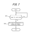
- FIG. 7 is a flowchart representing an example of operations by the electronic device according to Embodiment 2;
- FIG. 8 is a functional block diagram of an electronic device according to Embodiment 3.
- FIG. 9 illustrates another example of the relationship between the effective frequency band of the first piezoelectric element and that of the second piezoelectric element according to Embodiment 3;
- FIG. 10 is a flowchart representing another example of operations by the electronic device according to Embodiment 3.
- FIG. 11 is a functional block diagram of an electronic device according to Embodiment 4.
- FIGS. 12(A) and 12(B) illustrate an example of a housing structure of the electronic device according to Embodiment 4.
- FIG. 13 is a flowchart illustrating processing by the electronic device according to Embodiment 4.
- FIG. 14 is a flowchart illustrating processing by an electronic device according to Embodiment 5.
- FIG. 15 is a functional block diagram of an electronic device according to Embodiment 6;
- FIGS. 16(A) and 16(B) illustrate an example of a housing structure of the electronic device according to Embodiment 6;
- FIG. 17 is a flowchart illustrating processing by the electronic device according to Embodiment 6;
- FIG. 18 is a flowchart illustrating processing by the electronic device according to Embodiment 7.
- FIG. 19 is a functional block diagram of an electronic device according to Embodiment 8.
- FIGS. 20(A) and 20(B) illustrate an example of a housing structure of the electronic device according to Embodiment 8;
- FIG. 21 is a flowchart illustrating processing by the electronic device according to Embodiment 8.
- FIG. 22 is a flowchart illustrating processing by the electronic device according to Embodiment 9;
- FIG. 23 is a functional block diagram of a panel device according to Embodiment 10.
- FIG. 24 illustrates a housing structure of the panel device according to Embodiment 10.
- FIG. 25 is a functional block diagram of an electronic device according to Embodiment 11.
- FIGS. 26(A) and 26(B) illustrate an example of a housing structure of the electronic device according to Embodiment 11;
- FIG. 27 is a flowchart illustrating processing by the electronic device according to Embodiment 11;
- FIG. 28 is a flowchart illustrating processing by the electronic device according to Embodiment 12.
- FIG. 29 is a functional block diagram of an electronic device according to Embodiment 13;
- FIGS. 30(A) and 30(B) illustrate an example of a housing structure of the electronic device according to Embodiment 13;
- FIG. 31 is a flowchart illustrating processing by the electronic device according to Embodiment 13;
- FIG. 32 is a flowchart illustrating processing by the electronic device according to Embodiment 14.
- FIGS. 33( a ) and 33( b ) illustrate an example of vibration of a panel in an electronic device according to the present invention.
- FIG. 1 is a functional block diagram of an electronic device 1 b according to an embodiment of the present invention.
- the electronic device 1 b is, for example, a mobile phone (smartphone) and includes a panel 10 , a display unit 20 , a vibration unit 30 , a detection unit 40 , a control unit 50 , and a communication unit 70 .
- vibration of the panel 10 caused by the vibration unit 30 generates sound that is transmitted inside the human body.
- the sound is transmitted inside the human body by vibration of the middle ear or the inner ear via soft tissue (such as cartilage) of the human body.
- the panel 10 is a touch panel that detects contact or is a cover panel or the like that protects the display unit 20 .
- the panel 10 is, for example, made from glass or a synthetic resin such as acrylic or the like.
- the panel 10 is preferably plate-like in shape.
- the panel 10 may be a flat plate or may be a curved panel, the surface of which is smoothly inclined.
- the panel 10 detects contact by the user's finger, a pen, a stylus pen, or the like.
- Any detection system may be used in the touch panel, such as a capacitive system, a resistive film system, a surface acoustic wave system (or an ultrasonic wave system), an infrared system, an electromagnetic induction system, a load detection system, or the like.
- the panel 10 is preferably rectangular.
- the display unit 20 is a display device such as a liquid crystal display, an organic EL display, an inorganic EL display, or the like.
- the display unit 20 is provided on the back face of the panel 10 .
- the display unit 20 is disposed on the back face of the panel 10 by a joining member (for example, adhesive).
- the display unit 20 may be disposed at a distance from the panel 10 and supported by the housing of the electronic device 1 .
- the vibration unit 30 is formed by elements that, upon application of an electric signal (voltage), either expand and contract or bend (flex) in accordance with the electromechanical coupling coefficient of their constituent material. Ceramic or crystal elements, for example, may be used for the vibration unit 30 .
- the vibration unit 30 may be a unimorph, bimorph, or laminated piezoelectric element. Examples of a laminated piezoelectric element include a laminated unimorph element with layers of unimorph (for example, 16 or 24 layers) and a laminated bimorph element with layers of bimorph (for example, 16 or 24 layers).
- Such a laminated piezoelectric element may be configured with a laminated structure formed by a plurality of dielectric layers composed of, for example, lead zirconate titanate (PZT) and electrode layers disposed between the dielectric layers. Unimorph expands and contracts upon the application of an electric signal (voltage), and bimorph bends upon the application of an electric signal (voltage).
- the vibration unit 30 is a piezoelectric element for transmitting sound.
- the vibration unit 30 is preferably disposed on the back face of the panel 10 by a joining member (for example, adhesive).
- the detection unit 40 detects pressure on the panel 10 and is configured using, for example, an element such as a strain gauge sensor, a piezoelectric element, or the like that experiences a change in physical or electrical characteristics (strain, resistance, voltage, or the like) in response to pressure.
- an element such as a strain gauge sensor, a piezoelectric element, or the like that experiences a change in physical or electrical characteristics (strain, resistance, voltage, or the like) in response to pressure.
- the control unit 50 acquires the data by the detection unit 40 notifying the control unit 50 of the data, or by the control unit 50 detecting data pertaining to the piezoelectric element of the detection unit 40 . In other words, the control unit 50 acquires the data based on pressure on the touch face of the panel 10 from the detection unit 40 .
- the vibration unit 30 may be configured using a piezoelectric element that also serves as the detection unit 40 .
- the control unit 50 applies an electric signal to the vibration unit 30 to drive the vibration unit 30 , thus controlling sound output.
- the voltage that the control unit 50 applies to the vibration unit 30 may, for example, be ⁇ 15 V. This is higher than ⁇ 5 V, i.e. the applied voltage of a so-called panel speaker for conduction of sound by air-conducted sound rather than vibration sound. Note that the magnitude of the applied voltage used may be appropriately adjusted in accordance with the fixation strength of the panel 10 with respect to the housing or a support member, or in accordance with the performance of the vibration unit 30 .
- the control unit 50 drives the vibration unit 30 based on a trigger for sound output from a predetermined application or the like (based on an audio signal or the like).
- the control unit 50 varies the intensity of vibration of the vibration unit 30 in accordance with a force that is applied to the panel 10 and detected by the detection unit 40 .
- the control unit 50 makes the vibration of the panel 10 larger than when the force applied to the panel 10 is less than the predetermined threshold.
- the control unit 50 makes the voltage applied to the vibration unit 30 larger than when the force is less than the predetermined threshold.
- the control unit 50 sets the vibration amplitude of the vibration unit 30 to A and causes the vibration unit 30 to vibrate. Conversely, when the force applied to the panel 10 is less than the predetermined threshold, the control unit 50 sets the vibration amplitude of the vibration unit 30 to B (in this case, A>B) and causes the vibration unit 30 to vibrate.
- the predetermined threshold is preferably 5 N or the data value (such as 1 V) based on pressure detected (acquired) by the control unit 50 when a force of 5 N is applied to the panel 10 .
- the vibration unit 30 to which the electric signal is applied expands and contracts in the direction of the long sides.
- the panel 10 to which the vibration unit 30 is attached deforms in conjunction with the expansion and contraction of the vibration unit 30 .
- the panel 10 thus vibrates.
- the panel 10 flexes due to expansion and contraction or bending of the vibration unit 30 .
- the panel 10 is bent directly by the vibration unit 30 .
- Stating that “the panel 10 is bent directly by the vibration unit” differs from the phenomenon utilized in known panel speakers, whereby the panel deforms upon vibration of a particular region of the panel due to the inertial force of a piezoelectric actuator constituted by a vibration unit disposed in the casing.
- the panel 10 is bent directly by the vibration unit refers instead to how expansion and contraction or bending (flexure) of the vibration unit directly bends the panel via the joining member or via the joining member and the below-described reinforcing member.
- the panel 10 When the vibration unit 30 expands and contracts and the panel 10 vibrates, then along with generating air-conducted sound, the panel 10 generates vibration sound that is transmitted via a part of the user's body when the user brings a part of the body (such as the cartilage of the outer ear) into contact.
- the control unit 50 transmits air-conducted sound and vibration sound to an object that contacts the panel 10 .
- the control unit 50 can apply an electric signal, corresponding to an audio signal related to the other party's voice, to the vibration unit 30 to generate air-conducted sound and vibration sound that correspond to the audio signal.
- the audio signal may be related to ringtones, music including songs, or the like. Note that the audio signal pertaining to the electric signal may be based on music data stored in internal memory of the electronic device 1 , or may be music data stored on an external server or the like and played back over a network.
- the panel 10 vibrates not only in the region in which the vibration unit 30 is attached, but also in a region separate from the attachment region.
- the panel 10 includes a plurality of locations at which the panel 10 vibrates in a direction intersecting the main surface of the panel 10 .
- the value of the vibration amplitude changes over time from positive to negative or vice-versa.
- portions with a relatively large vibration amplitude and portions with a relatively small vibration amplitude appear to be distributed randomly or cyclically over nearly the entire panel 10 . In other words, a plurality of vibration waves are detected across the entire panel 10 .
- the communication unit 70 is used to communicate with other electronic devices or the like. With the communication unit 70 , the user of the electronic device 1 can talk with the user of another electronic device or the like. During a call, a microphone (not illustrated) picks up the sound spoken by the user of the electronic device 1 . The panel 10 also vibrates to output sound spoken by the user of another electronic device or the like.
- FIG. 2 illustrates a housing structure of the electronic device 1 according to the present embodiment.
- the electronic device 1 illustrated in FIG. 2 is a smartphone in which a touch panel that is a glass plate is disposed on the front face of a housing 60 (for example a metal or resin case) as the panel 10 .
- the panel 10 is supported by the housing 60 , and the display unit 20 and vibration unit 30 are each adhered to the panel 10 by a joining member.
- the joining member is adhesive with thermosetting properties, ultraviolet curable properties, or other such properties; double-sided tape; or the like.
- the joining member may, for example, be optical elasticity resin, which is clear and colorless acrylic ultraviolet curing adhesive.
- the panel 10 , the display unit 20 , and the vibration unit 30 are rectangular, yet this example is not limiting.
- the display unit 20 is disposed in approximately the center in the transverse direction of the panel 10 .
- the vibration unit 30 is disposed at a predetermined distance from an edge of the panel 10 in the longitudinal direction, near the edge so that the direction of the long sides of the vibration unit 30 extends along a short side of the panel 10 .
- the display unit 20 and the vibration unit 30 are disposed side by side, in parallel directions, on the inner face of the panel 10 .
- control unit 50 detects whether there is a trigger for sound output from a predetermined application or the like (step S 1 ). When there is a trigger for sound output, processing proceeds to step S 2 . When there is no trigger for sound output, step S 1 is repeated.
- control unit 50 determines whether the force that is applied to the panel 10 and detected by the detection unit 40 is a predetermined threshold or greater (step S 2 ). When the force is a predetermined threshold or greater, processing proceeds to step S 3 . When the force is less than a predetermined threshold, processing proceeds to step S 4 .
- the control unit 50 sets the vibration amplitude of the vibration unit 30 to A and causes the vibration unit 30 to vibrate (step S 3 ). Processing then terminates. Conversely, when the force applied to the panel 10 is less than a predetermined threshold, the control unit 50 sets the vibration amplitude of the vibration unit 30 to B and causes the vibration unit 30 to vibrate (step S 4 ). Processing then terminates.
- the electronic device 1 of the present embodiment even if a force is applied to the panel 10 by the ear, the intensity of vibration of the vibration unit 30 is changed in accordance with the force applied to the panel 10 . Hence, sound can be effectively transmitted.
- the electronic device 1 can transmit, to the user, air-conducted sound as well as vibration sound that is transmitted through a part of the user's body (such as the cartilage of the outer ear). Therefore, when sound is output at a volume equivalent to a known dynamic receiver, the sound that is transmitted to the periphery of the electronic device 1 by air vibrations due to vibration of the panel 10 is smaller than with a dynamic receiver. Accordingly, the electronic device 1 is appropriate for listening to recorded messages, for example, on the train or the like.
- the electronic device 1 transmits vibration sound by vibration of the panel 10 , and therefore even if the user is wearing earphones or headphones, for example, the user can hear sound through the earphones or headphones and through a part of the body by contacting the electronic device 1 against the earphones or headphones.
- the electronic device 1 transmits sound to a user by vibration of the panel 10 . Therefore, if the electronic device 1 is not provided with a separate dynamic receiver, it is unnecessary to form an opening (sound discharge port) for sound transmission in the housing 60 , thereby simplifying waterproof construction of the electronic device 1 . On the other hand, if the electronic device 1 is provided with a dynamic receiver, the sound discharge port should be blocked by a member permeable by gas but not liquid. Gore-Tex (registered trademark) is an example of a member permeable by gas but not liquid.
- the above electronic device 1 varies the intensity of vibration in accordance with the force applied to the panel 10 between two levels based on a predetermined threshold, yet this example is not limiting.
- a plurality of thresholds may be established to vary the intensity between multiple levels.
- the intensity of vibration may be varied continuously in accordance with the force applied to the panel 10 .
- FIG. 4 is a functional block diagram of an electronic device 1 b according to Embodiment 2 of the present invention.
- the electronic device 1 b is, for example, a mobile phone (smartphone) and is provided with a panel 10 , a display unit 20 , a first piezoelectric element 31 b , a second piezoelectric element 32 b , an input unit 40 b , and a control unit 50 b .
- vibration of the panel 10 caused by the first piezoelectric element 32 b and the second piezoelectric element 32 b generates sound transmitted inside the human body.
- the sound is transmitted inside the human body by vibration of the middle ear or the inner ear via soft tissue (such as cartilage) of the human body.
- the first piezoelectric element 31 b is formed by elements that, upon application of an electric signal (voltage), either expand and contract or bend (flex) in accordance with the electromechanical coupling coefficient of their constituent material. Ceramic or crystal elements, for example, may be used.
- the first piezoelectric element 31 b may be a unimorph, bimorph, or laminated piezoelectric element. Examples of a laminated piezoelectric element include a laminated unimorph element with layers of unimorph (for example, 16 or 24 layers) and a laminated bimorph element with layers of bimorph (for example, 16 or 24 layers).
- Such a laminated piezoelectric element may be configured with a laminated structure formed by a plurality of dielectric layers composed of, for example, lead zirconate titanate (PZT) and electrode layers disposed between the dielectric layers.
- PZT lead zirconate titanate
- Unimorph expands and contracts upon the application of an electric signal (voltage), and bimorph bends upon the application of an electric signal (voltage).
- the first piezoelectric element 31 b is a piezoelectric element for providing a tactile sensation to a contacting object that is in contact with the panel 10 .
- the first piezoelectric element 31 b is preferably rectangular, expanding or contracting in the direction of the long sides.
- the first piezoelectric element 31 b is preferably disposed on the back face of the panel 10 by a joining member (for example, adhesive).
- the second piezoelectric element 32 b is formed by elements that, upon application of an electric signal (voltage), either expand and contract or bend (flex) in accordance with the electromechanical coupling coefficient of their constituent material. Ceramic or crystal elements, for example, may be used.
- the second piezoelectric element 32 b may be a unimorph, bimorph, or laminated piezoelectric element. Examples of a laminated piezoelectric element include a laminated unimorph element with layers of unimorph (for example, 16 or 24 layers) and a laminated bimorph element with layers of bimorph (for example, 16 or 24 layers).
- Such a laminated piezoelectric element may be configured with a laminated structure formed by a plurality of dielectric layers composed of, for example, lead zirconate titanate (PZT) and electrode layers disposed between the dielectric layers. Unimorph expands and contracts upon the application of an electric signal (voltage), and bimorph bends upon the application of an electric signal (voltage).
- the second piezoelectric element 32 b is a piezoelectric element for transmitting sound.
- the second piezoelectric element 32 b is preferably rectangular, expanding or contracting in the direction of the long sides.
- the second piezoelectric element 32 b is preferably disposed on the back face of the panel 10 by a joining member (for example, adhesive).
- the input unit 40 b detects operation input by the user and may be configured, for example, using operation buttons (operation keys). Note that when the panel 10 is a touch panel, the panel 10 can also detect an operation by the user by detecting contact by the user.
- the control unit 50 b is a processor that controls the electronic device 1 b .
- the control unit 50 b applies a predetermined electric signal to the first piezoelectric element 31 b and the second piezoelectric element 32 b .
- the control unit 50 b applies an electric signal to the first piezoelectric element 31 b to drive the first piezoelectric element 31 b .
- the electronic device 1 b may include a pressure detection unit (not illustrated) that detects pressure on the panel 10 .
- the first piezoelectric element 31 b may then be driven upon data based on pressure on the panel 10 satisfying a predetermined standard.
- the pressure detection unit detects pressure on the panel 10 and is configured using, for example, an element such as a strain gauge sensor, a piezoelectric element, or the like that experiences a change in physical or electrical characteristics (strain, resistance, voltage, or the like) in response to pressure.
- an element such as a strain gauge sensor, a piezoelectric element, or the like that experiences a change in physical or electrical characteristics (strain, resistance, voltage, or the like) in response to pressure.
- the control unit 50 b acquires the data by the pressure detection unit notifying the control unit 50 b of the data, or by the control unit 50 b detecting data pertaining to the piezoelectric element of the pressure detection unit. In other words, the control unit 50 b acquires the data based on pressure on the touch face of the panel 10 from the pressure detection unit. Note that when the pressure detection unit is configured using a piezoelectric element, the first piezoelectric element 31 b may also serve as the pressure detection unit.
- the control unit 50 b also applies an electric signal to the second piezoelectric element 32 b to drive the second piezoelectric element 32 b , thus controlling sound output.
- the voltage that the control unit 50 b applies to the second piezoelectric element 32 b may, for example, be ⁇ 15 V. This is higher than ⁇ 5 V, i.e. the applied voltage of a so-called panel speaker for conduction of sound by air-conducted sound rather than vibration sound. In this way, even if the user presses the panel 10 against the user's body for example with a force of 3 N or greater (a force of 5 N to 10 N), sufficient vibration is generated in the panel 10 to allow for generation of a vibration sound transmitted via a part of the user's body.
- the control unit 50 b also drives the second piezoelectric element 32 b based on a trigger for sound output from a predetermined application or the like (based on an audio signal (sound signal) or the like).
- the control unit 50 b When outputting sound, the control unit 50 b also performs control to drive the first piezoelectric element 31 b in addition to the second piezoelectric element 32 b .
- the control unit 50 b includes a signal combiner 51 .
- the signal combiner 51 combines the control signal pertaining to provision of a tactile sensation and the control signal pertaining to sound output, providing the result to the first piezoelectric element 31 b . Since the signal combiner 51 of the control unit 50 b thus combines the control signal pertaining to provision of a tactile sensation and the control signal pertaining to sound output, the tactile sensation providing function of the first piezoelectric element 31 b is not obstructed.
- the first piezoelectric element 31 b is a piezoelectric element for providing a tactile sensation to a contacting object that is in contact with the panel 10 .
- the piezoelectric element for providing a tactile sensation is preferably larger in size than the piezoelectric element for transmitting sound.
- the first piezoelectric element 31 b is preferably larger than the second piezoelectric element 32 b . Therefore, the resonance frequency of the first piezoelectric element 31 b is lower than the resonance frequency of the second piezoelectric element 32 b .
- the first piezoelectric element 31 b preferably transmits low-pitched sound
- the second piezoelectric element 32 b preferably transmits high-pitched sound.
- FIGS. 5( a ) and 5( b ) illustrate the relationship between the effective frequency band of the first piezoelectric element 31 b and that of the second piezoelectric element 32 b in Embodiment 2.
- the effective frequency band of the piezoelectric element is the effective frequency band in which the piezoelectric element can emit aurally effective sound.
- the effective frequency band of the piezoelectric element is the band of the frequencies having an amplitude of at least 1 ⁇ 2 of the maximum amplitude.
- FIG. 5( b ) is a conceptual diagram pertaining to the resonance frequency and the effective frequency band of a certain piezoelectric element. In FIG.
- the resonance frequency is Fx
- the effective frequency band is from Fy to Fz.
- the amplitude at Fx is Ax.
- the amplitude at a certain frequency Fy (Fy ⁇ Fx) is Ay
- the amplitude at a certain frequency Fz (Fx ⁇ Fz) is Az.
- Ay and Az are 1 ⁇ 2 of Ax
- the amplitude between Fy and Fz is 1 ⁇ 2 or more of Ax.
- the effective frequency band may, for example, be the band of frequencies having an amplitude of at least 1 ⁇ 3 of the maximum amplitude and may be set appropriately in accordance with the product being used.
- the effective frequency band may also be a 3 dB bandwidth centering on the resonance frequency.
- the resonance frequency and the effective frequency band of the piezoelectric element may also be the resonance frequency and effective frequency band in a vibration system with the piezoelectric element mounted on a touch panel.
- the effective frequency band of the first piezoelectric element 31 b and the effective frequency band of the second piezoelectric element 32 b do not overlap.
- the effective frequency band of the first piezoelectric element 31 b is 1 Hz or more to less than 400 Hz
- the effective frequency band of the second piezoelectric element 32 b is 400 Hz or more to less than 20000 Hz.
- the control unit 50 b when outputting sound the control unit 50 b performs control so that the sound included in the effective frequency band of the first piezoelectric element 31 b is output by the first piezoelectric element 31 b , and the sound included in the effective frequency band of the second piezoelectric element 32 b is output by the second piezoelectric element 32 b .
- the first piezoelectric element 31 b and the second piezoelectric element 32 b complement each other.
- the first piezoelectric element 31 b and the second piezoelectric element 32 b to which the electric signal has been applied expand and contract in the direction of the long sides.
- the panel 10 to which the first piezoelectric element 31 b and the second piezoelectric element 32 b are attached deforms in accordance with expansion and contraction of the first piezoelectric element 31 b and the second piezoelectric element 32 b , and the panel 10 vibrates.
- the panel 10 flexes due to expansion and contraction or to bending of the first piezoelectric element 31 b and the second piezoelectric element 32 b .
- the panel 10 is bent directly by the first piezoelectric element 31 b and the second piezoelectric element 32 b .
- the panel 10 is bent directly by the piezoelectric element” differs from the phenomenon utilized in known panel speakers, whereby the panel deforms upon vibration of a particular region of the panel due to the inertial force of a piezoelectric actuator constituted by a vibration unit disposed in the casing.
- the panel 10 is bent directly by the piezoelectric element refers instead to how expansion and contraction or bending (flexure) of the piezoelectric element directly bends the panel via the joining member or via the joining member and the below-described reinforcing member.
- the control unit 50 b transmits air-conducted sound and vibration sound to an object that contacts the panel 10 .
- the control unit 50 b can apply an electric signal, corresponding to an audio signal related to the other party's voice, to the second piezoelectric element 32 b to generate air-conducted sound and vibration sound that correspond to the audio signal.
- the audio signal may be related to ringtones, music including songs, or the like. Note that the audio signal pertaining to the electric signal may be based on music data stored in internal memory of the electronic device 1 b , or may be music data stored on an external server or the like and played back over a network.
- the panel 10 vibrates not only in the region in which the first piezoelectric element 31 b and the second piezoelectric element 32 b are attached, but also in a region separate from the attachment region.
- the panel 10 includes a plurality of locations at which the panel 10 vibrates in a direction intersecting the main surface of the panel 10 . At each of these locations, the value of the vibration amplitude changes over time from positive to negative or vice-versa.
- portions with a relatively large vibration amplitude and portions with a relatively small vibration amplitude appear to be distributed randomly or cyclically over nearly the entire panel 10 . In other words, a plurality of vibration waves are detected across the entire panel 10 .
- the voltage that the control unit 50 b applies to the second piezoelectric element 32 b may be ⁇ 15 V to prevent damping of the above-described vibration of the panel 10 even if the user presses the panel 10 against the user's body with a force of, for example, 5 N to 10 N. Therefore, the user can hear sound by contacting a region distant from the above-described attachment region of the panel 10 to the ear.
- FIG. 6 illustrates a housing structure of the electronic device 2 b according to the present embodiment.
- the electronic device 1 b illustrated in FIG. 6 is a smartphone in which a touch panel that is a glass plate is disposed on the front face of a housing 60 (for example a metal or resin case) as the panel 10 .
- the panel 10 and the input unit 40 b are supported by the housing 60 , and the display unit 20 , first piezoelectric element 31 b , and second piezoelectric element 32 b are each adhered to the panel 10 by a joining member.
- the joining member is adhesive with thermosetting properties, ultraviolet curable properties, or other such properties; double-sided tape; or the like.
- the joining member may, for example, be optical elasticity resin, which is clear and colorless acrylic ultraviolet curing adhesive.
- the panel 10 , display unit 20 , first piezoelectric element 31 b , and second piezoelectric element 32 b are each rectangular.
- the display unit 20 is disposed in approximately the center in the transverse direction of the panel 10 .
- the first piezoelectric element 31 b is disposed at a predetermined distance from an edge of the panel 10 in the longitudinal direction, near the edge so that the direction of the long sides of the first piezoelectric element 31 b extends along a short side of the panel 10 .
- the display unit 20 and the first piezoelectric element 31 b are disposed side by side, in parallel directions, on the inner face of the panel 10 .
- the second piezoelectric element 32 b is disposed at a predetermined distance from an edge of the panel 10 in the longitudinal direction, near the edge so that the direction of the long sides of the second piezoelectric element 32 b extends along a short side of the panel 10 .
- the positions at which the first piezoelectric element 31 b and the second piezoelectric element 32 b are disposed are only non-limiting examples.
- the second piezoelectric element 32 b may be disposed so that the direction of the long sides thereof extends along a long side of the panel 10 .
- the second piezoelectric element 32 b may be disposed near the opposite edge from the edge at which the first piezoelectric element 31 b is disposed.
- first piezoelectric element 31 b and the second piezoelectric element 32 b may respectively be disposed along the two short sides. This case is preferable in that the first piezoelectric element 31 b and the second piezoelectric element 32 b do not operate in a direction to obstruct each other's vibration.
- control unit 50 b detects whether there is a trigger for sound output from a predetermined application or the like (step S 11 ). When there is a trigger for sound output, processing proceeds to step S 12 . When there is no trigger for sound output, step S 11 is repeated.
- control unit 50 b when outputting sound the control unit 50 b performs control so that the sound included in the effective frequency band of the first piezoelectric element 31 b is output by the first piezoelectric element 31 b , and the sound included in the effective frequency band of the second piezoelectric element 32 b is output by the second piezoelectric element 32 b (step S 12 ). Processing then terminates.
- the electronic device 1 b of the present embodiment when outputting sound, the sound included in the effective frequency band of the first piezoelectric element 31 b is output by the first piezoelectric element 31 b , and the sound included in the effective frequency band of the second piezoelectric element 32 b is output by the second piezoelectric element 32 b . Therefore, in the case that a piezoelectric element for the tactile sensation providing function and a piezoelectric element for the function to transmit air-conducted sound and the like are provided, the first piezoelectric element 31 b and the second piezoelectric element 32 b output sound while complementing each other's effective frequency band, thereby improving the acoustic effect.
- the electronic device 1 b can transmit, to the user, air-conducted sound as well as vibration sound that is transmitted through a part of the user's body (such as the cartilage of the outer ear). Therefore, when sound is output at a volume equivalent to a known dynamic receiver, the sound that is transmitted to the periphery of the electronic device 1 b by air vibrations due to vibration of the panel 10 is smaller than with a dynamic receiver. Accordingly, the electronic device 1 b is appropriate for listening to recorded messages, for example, on the train or the like.
- the electronic device 1 b transmits vibration sound by vibration of the panel 10 , and therefore even if the user is wearing earphones or headphones, for example, the user can hear sound through the earphones or headphones and through a part of the body by contacting the electronic device 1 b against the earphones or headphones.
- the electronic device 1 b transmits sound to a user by vibration of the panel 10 . Therefore, if the electronic device 1 b is not provided with a separate dynamic receiver, it is unnecessary to form an opening (sound discharge port) for sound transmission in the housing 60 , thereby simplifying waterproof construction of the electronic device 1 b . On the other hand, if the electronic device 1 b is provided with a dynamic receiver, the sound discharge port should be blocked by a member permeable by gas but not liquid. Gore-Tex (registered trademark) is an example of a member permeable by gas but not liquid.
- Embodiment 3 of the present invention differs from the electronic device 1 b of Embodiment 1 in the relationship between the effective frequency bands of the first piezoelectric element 31 b and the second piezoelectric element 32 b .
- the difference is that the effective frequency band of the first piezoelectric element 31 b overlaps with the effective frequency band of the second piezoelectric element 32 b.
- FIG. 8 is a functional block diagram of an electronic device 2 b according to Embodiment 3 of the present invention.
- the electronic device 2 b according to Embodiment 2 differs in that, in addition to the structure of the electronic device 1 b according to Embodiment 1, the control unit 50 b includes a band separator 52 .
- the band separator 52 separates the frequency band so that the combined frequency characteristic becomes flat.
- the volume of the frequency region in which the effective frequency band of the first piezoelectric element 31 b and the effective frequency band of the second piezoelectric element 32 b overlap becomes extremely large as compared to the volume of other frequency regions. Therefore, based on the frequency band, the band separator 52 separates the signal pertaining to sound that is output so that the volume of the overlapping frequency region does not diverge too far from the volume of the non-overlapping portion and provides the separated signals to the first piezoelectric element 31 b and the second piezoelectric element 32 b.
- the user may wish to emphasize output of low-pitched sound, for example for a low-frequency effect.
- it is effective for the band separator 52 not to separate the signal pertaining to sound that is output so that the volume of the frequency region in which the effective frequency band of the first piezoelectric element 31 b overlaps with the effective frequency band of the second piezoelectric element 32 b , i.e. the low-pitched sound, is greater than the volume of other frequency regions.
- FIG. 9 illustrates the relationship between the effective frequency band of the first piezoelectric element 31 b and that of the second piezoelectric element 32 b according to Embodiment 2.
- the effective frequency band of the first piezoelectric element 31 b and the effective frequency band of the second piezoelectric element 32 b overlap.
- the effective frequency band of the first piezoelectric element 31 b is 1 Hz or more to less than 400 Hz
- the effective frequency band of the second piezoelectric element 32 b is 200 Hz or more to less than 20000 Hz.
- the control unit 50 b when emphasizing low-pitched sound in the sound that is output, the control unit 50 b also performs control to drive the first piezoelectric element 31 b in addition to the second piezoelectric element 32 b .
- the control unit 50 b drives the second piezoelectric element 32 b without driving the first piezoelectric element 31 b .
- the input unit 40 b detects operation input from the user regarding whether to emphasize low-pitched sound. Based on the operation input from the user, the input unit 40 b turns a setting to emphasize low-pitched sound (referred to below as a “low-pitched sound emphasis setting”) on or off.
- step S 11 the control unit 50 b determines whether the low-pitched sound emphasis setting of the electronic device 2 b is turned on (step S 22 ). When the low-pitched sound emphasis setting is turned on, processing proceeds to step S 23 . When the low-pitched sound emphasis setting is turned off, processing proceeds to step S 24 .
- the control unit 50 b When the low-pitched sound emphasis setting is turned on, the control unit 50 b also performs control to drive the first piezoelectric element 31 b in addition to the second piezoelectric element 32 b for the sound that is output (step S 23 ). Processing then terminates. On the other hand, when the low-pitched sound emphasis setting is turned off, the control unit 50 b drives the second piezoelectric element 32 b without driving the first piezoelectric element 31 b (step S 24 ). Processing then terminates.
- the low-pitched sound emphasis setting is switched by using the first piezoelectric element 31 b and the second piezoelectric element 32 b or only using the second piezoelectric element 32 b , yet switching is not limited in this way.
- the intensity of vibration of the first piezoelectric element 31 b may be varied in addition to the second piezoelectric element 32 b .
- the band that is separated by the band separator 52 may be varied.
- the electronic device according to Embodiment 4 of the present invention may be a mobile phone, a smartphone, a tablet PC, or the like provided with a touch panel.
- the present invention is not, however, limited to such mobile devices and may be any of a variety of electronic devices such as a household appliance, industrial device (factory automation equipment), dedicated terminal, or the like provided with a touch panel.
- FIG. 11 is a functional block diagram of an electronic device according to Embodiment 4 of the present invention.
- an electronic device 1 c includes a panel 10 c , a display unit 20 c , a first piezoelectric element 31 c , a second piezoelectric element 32 c , an input unit 40 c , and a control unit 50 c .
- vibration of the panel 10 c caused by the second piezoelectric element 32 c generates sound that is transmitted inside the human body.
- the sound is transmitted inside the human body by vibration of the middle ear or the inner ear via soft tissue (such as cartilage) of the human body.
- the panel 10 c may be a touch panel that detects contact or a cover panel or the like that protects the display unit 20 c .
- the panel 10 c is preferably made from, for example, glass or a synthetic resin such as acrylic or the like.
- the panel 10 c is, for example, made from glass or a synthetic resin such as acrylic or the like.
- the panel 10 c is preferably plate-like in shape.
- the panel 10 c may be a flat plate or may be a curved panel, the surface of which is smoothly inclined.
- the panel 10 c detects contact by the user's finger, a stylus pen, or the like.
- Any detection system may be used in the touch panel, such as a capacitive system, a resistive film system, an optical system, a surface acoustic wave system (or an ultrasonic wave system), an infrared system, an electromagnetic induction system, a load detection system, or the like.
- the panel 10 c is preferably disposed in a housing or the like in a manner allowing for vibration.
- the panel 10 c is preferably disposed in the housing or the like in a manner allowing for vibration by, for example, disposing the panel 10 c on the housing via an elastic member or partially fixing the panel 10 c to the housing.
- the panel 10 c When the panel 10 c is configured using a member such as a touch panel, the panel 10 c detects contact on the touch face by the user's finger, a stylus pen, or the like, and outputs information on the position of the contact. With this output, the control unit 50 c can acquire the position of contact detected by the panel 10 c.
- the display unit 20 c is a display device such as a liquid crystal display, an organic EL display, an inorganic EL display, or the like.
- the display unit 20 c can display a variety of information and images, as well as objects such as keys, buttons, or the like on the screen.
- the display unit 20 c is provided on the back face of the panel 10 c .
- the display unit 20 c is disposed on the back face of the panel 10 c by a joining member (for example, adhesive).
- the display unit 20 c may be disposed at a distance from the panel 10 c and supported by the housing of the electronic device 1 c .
- the panel 10 c is preferably configured using, for example, a transparent member or the like, with the display unit 20 c disposed at the back face thereof.
- an object such as a key, button, or the like can be rendered on the display unit 20 c , and an operation by which the user presses the object can be detected on the panel 10 c .
- Such display on the display unit 20 c can be implemented by control with the control unit 50 c.
- the first piezoelectric element 31 c and the second piezoelectric element 32 c are formed by elements that, upon application of an electric signal (voltage), either expand and contract or bend (flex) in accordance with the electromechanical coupling coefficient of their constituent material.
- ceramic or crystal elements for example, may be used.
- the first piezoelectric element 31 c and the second piezoelectric element 32 c may be a unimorph, bimorph, or laminated piezoelectric element.
- Examples of a laminated piezoelectric element include a laminated unimorph element with layers of unimorph (for example, 16 or 24 layers) and a laminated bimorph element with layers of bimorph (for example, 16 or 24 layers).
- Such a laminated piezoelectric element may be configured with a laminated structure formed by a plurality of dielectric layers composed of, for example, lead zirconate titanate (PZT) and electrode layers disposed between the dielectric layers.
- PZT lead zirconate titanate
- Unimorph expands and contracts upon the application of an electric signal (voltage), and bimorph bends upon the application of an electric signal (voltage).
- the first piezoelectric element 31 c and the second piezoelectric element 32 c are preferably disposed on the back face of the panel 10 c (the side facing the inside of the electronic device 1 c ).
- the first piezoelectric element 31 c and the second piezoelectric element 32 c are attached to the panel 10 c by a joining member (for example, double-sided tape).
- the first piezoelectric element 31 c and the second piezoelectric element 32 c may be attached to the panel 10 c with an intermediate member (for example, sheet metal) therebetween.
- the first piezoelectric element 31 c and the second piezoelectric element 32 c are preferably separated from the inner surface of the housing by the predetermined distance even when expanding and contracting or bending.
- the distance between the first piezoelectric element 31 c and second piezoelectric element 32 c and the inner face of the housing is preferably larger than the maximum amount of deformation of the first piezoelectric element 31 c and the second piezoelectric element 32 c.
- the first piezoelectric element 31 c is a piezoelectric element mainly used for providing a tactile sensation. Accordingly, the first piezoelectric element 31 c is preferably a piezoelectric element designed to have a suitable frequency characteristic for providing a predetermined tactile sensation based on an electric signal from the control unit 50 c .
- the second piezoelectric element 32 c is a piezoelectric element mainly used for transmitting sound. Accordingly, the second piezoelectric element 32 c is preferably a piezoelectric element designed to have a suitable frequency characteristic for transmitting a predetermined sound based on an electric signal from the control unit 50 c .
- the first piezoelectric element and the second piezoelectric element are thus disposed in the panel 10 c as different piezoelectric elements.
- the input unit 40 c detects operation input by the user and may be configured, for example, using operation buttons (operation keys).
- the input operation by the user detected by the input unit 40 c is transmitted to the control unit 50 c as an electric signal.
- the panel 10 c is a touch panel, the panel 10 c can also detect contact by the user.
- the control unit 50 c is a processor that controls the electronic device 1 c .
- the control unit 50 c applies a predetermined electric signal to the first piezoelectric element 31 c and the second piezoelectric element 32 c .
- the control unit 50 c applies an electric signal to the first piezoelectric element 31 c to drive the first piezoelectric element 31 c.
- the control unit 50 c also applies an electric signal to the second piezoelectric element 32 c to drive the second piezoelectric element 32 c , thus controlling sound output.
- the control unit 50 c can perform control to drive the second piezoelectric element 32 c based on a trigger for sound output from a predetermined application or the like (based on an audio signal (sound signal) or the like).
- the voltage that the control unit 50 c applies to the second piezoelectric element 32 c may, for example, be ⁇ 15 V. This is higher than ⁇ 5 V, i.e. the applied voltage of a so-called panel speaker for conduction of sound by air-conducted sound rather than vibration sound. In this way, even if the user presses the panel 10 c against the user's body for example with a force of 3 N or greater (a force of 5 N to 10 N), sufficient vibration is generated in the panel 10 c to allow for generation of a vibration sound transmitted via a part of the user's body.
- the magnitude of the applied voltage used may be appropriately adjusted in accordance with the fixation strength of the panel 10 c with respect to the housing or a support member, or in accordance with the performance of the first piezoelectric element 31 c or the second piezoelectric element 32 c.
- the first piezoelectric element 31 c and the second piezoelectric element 32 c to which the electric signal has been applied expand and contract in the direction of the long sides of each element.
- the panel 10 c to which the first piezoelectric element 31 c and the second piezoelectric element 32 c are attached deforms in accordance with expansion and contraction of the first piezoelectric element 31 c and the second piezoelectric element 32 c , and the panel 10 c vibrates.
- the panel 10 c flexes due to expansion and contraction or to bending of the first piezoelectric element 31 c and the second piezoelectric element 32 c .
- the panel 10 c is bent directly by the first piezoelectric element 31 c and the second piezoelectric element 32 c .
- Stating that “the panel 10 c is bent directly by the piezoelectric element” differs from the phenomenon utilized in known panel speakers, whereby the panel deforms upon vibration of a particular region of the panel due to the inertial force of a piezoelectric actuator constituted by a piezoelectric element disposed in the casing.
- the panel 10 c When the second piezoelectric element 32 c expands and contracts and the panel 10 c vibrates, then along with generating air-conducted sound, the panel 10 c generates vibration sound that is transmitted via a part of the user's body when the user brings a part of the body (such as the cartilage of the outer ear) into contact.
- the control unit 50 c transmits air-conducted sound and vibration sound to an object that contacts the panel 10 c .
- the control unit 50 c can apply an electric signal, corresponding to an audio signal related to the other party's voice, to the second piezoelectric element 32 c to generate air-conducted sound and vibration sound that correspond to the audio signal.
- the audio signal may be related to ringtones, music including songs, or the like. Note that the audio signal pertaining to the electric signal may be based on music data stored in internal memory of the electronic device 1 c , or may be music data stored on an external server or the like and played back over a network.
- the panel 10 c vibrates not only in the region in which the second piezoelectric element 32 c is attached, but also in a region separate from the attachment region.
- the panel 10 c includes a plurality of locations at which the panel 10 c vibrates in a direction intersecting the main surface of the panel 10 c .
- the value of the vibration amplitude changes over time from positive to negative or vice-versa.
- portions with a relatively large vibration amplitude and portions with a relatively small vibration amplitude appear to be distributed randomly or cyclically over nearly the entire panel 10 c . In other words, a plurality of vibration waves are detected across the entire panel 10 c .
- the voltage that the control unit 50 c applies to the second piezoelectric element 32 c may be ⁇ 15 V to suppress damping of the above-described vibration of the panel 10 c even if the user presses the panel 10 c against the user's body with a force of, for example, 5 N to 10 N. Therefore, the user can hear sound by contacting a region distant from the above-described attachment region of the panel 10 c to the ear.
- FIGS. 12(A) and 12(B) illustrate an example of a housing structure of the electronic device 1 c according to Embodiment 1.
- FIG. 12(A) is a front view
- FIG. 2(B) is a cross-sectional view along the C-C line in FIG. 2(A) .
- the electronic device 1 c illustrated in FIGS. 12(A) and 12(B) is a smartphone in which a touch panel that is a glass plate is disposed on the front face of a housing 60 (for example a metal or resin case) as the panel 10 c .
- the panel 10 c and the input unit 40 c are supported by the housing 60 .
- the display unit 20 c , first piezoelectric elements 31 c , and second piezoelectric element 32 c are each adhered to the panel 10 c via a joining member 70 . Note that in the example illustrated in FIG. 12(A) , the first piezoelectric elements 31 c and the second piezoelectric element 32 c are adhered to the back face of the panel.
- the joining member 70 is adhesive with thermosetting properties, ultraviolet curable properties, or other such properties; double-sided tape; or the like.
- the joining member 70 may, for example, be optical elasticity resin, which is clear and colorless acrylic ultraviolet curing adhesive.
- the panel 10 c , display unit 20 c , first piezoelectric elements 31 c , and second piezoelectric element 32 c are each generally rectangular.
- the display unit 20 c is disposed in approximately the center in the transverse direction of the panel 10 c .
- the first piezoelectric elements 31 c and the second piezoelectric element 32 c are disposed at a predetermined distance from an edge of the panel 10 c in the longitudinal direction, near the edge so that the longitudinal direction of the first piezoelectric elements 31 c and the second piezoelectric element 32 c extends along a short side of the panel 10 c.
- the display unit 20 c , first piezoelectric elements 31 c , and second piezoelectric element 32 c are disposed side by side, in parallel directions, on the back face of the panel 10 c , yet the arrangement of these components is not limited to this example.
- at least one of the first piezoelectric elements 31 c and the second piezoelectric element 32 c may be disposed in parallel to the longitudinal direction of the electronic device 1 c (the lengthwise direction in FIG. 12(A) ).
- any configuration that allows the first piezoelectric elements 31 c and the second piezoelectric element 32 c to transmit vibration to the panel 10 c by being attached to the panel 10 c may be adopted.
- FIGS. 12(A) and 12(B) illustrate a configuration in which the display unit 20 c is adhered to the back face of the panel 10 c via the joining member 70
- the arrangement of the display unit 20 c is also not limited to the illustrated example.
- the display unit 20 c may be adhered to the back face of the panel 10 c without the joining member 70 therebetween or may be disposed inside the housing 60 instead of being adhered to the panel 10 c .
- the display unit 20 c may be fixed directly on the inside of the housing 60 or may be fixed to a substrate, or to a holder for the display unit, disposed on the inside of the housing 60 .
- any user interface may be displayed on the display unit 20 c , and user operation can be detected by the panel 10 c .
- the display unit 20 c is illustrated with a dashed line to indicate that the display unit 20 c is adhered to the back face of the panel 10 c.
- FIGS. 12(A) and 12(B) in the space enclosed by the housing 60 and the panel 10 c , illustration is omitted for components other than the display unit 20 c , first piezoelectric elements 31 c , second piezoelectric element 32 c , input unit 40 c , and joining member 70 . Accordingly, apart from what is illustrated in FIGS. 12(A) and 12(B) , the electronic device 1 c may be provided with elements such as the control unit 50 c and a variety of substrates, components, or the like. Furthermore, in FIG. 12(A) , regarding the region in which display by the display unit 20 c does not need to be transmitted to the panel 10 c (i.e.
- the region near the edges of the panel 10 c is preferably painted or covered with a bezel.
- the first piezoelectric elements 31 c , second piezoelectric element 32 c , and the like can thus be prevented from being seen from the exterior of the electronic device 1 c.
- control unit 50 c the processing performed by the control unit 50 c according to the present embodiment is described.
- the control unit 50 c performs control to output sound by driving the second piezoelectric element 32 c .
- the second piezoelectric element can implement the function of outputting audio and transmitting the audio to the user.
- the control unit 50 c also performs control to drive the first piezoelectric elements 31 c upon the panel 10 c detecting contact. In this way, in the electronic device 1 c , the first piezoelectric elements can implement the function of providing a tactile sensation to the user by generating vibration.
- the processing described below is performed via control by the control unit 50 c.
- FIG. 13 is a flowchart illustrating processing by the control unit 50 c in the electronic device 1 c according to Embodiment 4.
- a trigger for outputting sound is envisioned as taking on a variety of forms, such as an instruction to sound a ring tone from a calling application when a call is received or an instruction to play back music or the like from a music player application.
- a trigger for outputting sound may be any instruction that serves as an occasion for vibrating the panel 10 c to output sound by driving the second piezoelectric element 32 c for sound output in the electronic device 1 c.
- step S 11 c When a trigger for outputting sound has occurred in step S 11 c , the control unit 50 c performs control to output sound by driving the second piezoelectric element 32 c (step S 12 c ).
- step S 12 c determines whether the panel 10 c has detected contact by the user's finger, ear, or the like (step S 13 c ). Note that when a trigger for outputting sound has not occurred in step S 11 c , the control unit 50 c proceeds to step S 13 c without driving the second piezoelectric element 32 c.
- step S 13 c When the panel 10 c has not detected contact in step S 13 c , the control unit 50 c returns to step S 11 c and continues processing. Conversely, when the panel 10 c has detected contact in step S 13 c , the control unit 50 c determines whether the second piezoelectric element is being driven (step S 14 c ).
- step S 14 c When determining in step S 14 c that the second piezoelectric element is not being driven, the control unit 50 c performs control to provide a tactile sensation by driving the first piezoelectric elements 31 c , since at this point, no problem of interference arises even if vibration is generated to provide a tactile sensation (step S 15 c ).
- step S 15 c when there is contact on the panel 10 c in step S 13 c and sound is not being output in step S 14 c , a tactile sensation is provided based on the contact. Accordingly, the user can confirm, via a tactile sensation, that the operation in which the user touched the panel 10 c has been properly detected by the electronic device 1 c.
- the control unit 50 c preferably performs control to execute predetermined processing associated with the position (step S 16 c ).
- this predetermined processing may be processing to launch the address book application.
- this predetermined processing may be processing to display the character key on the display unit 20 c.
- control unit 50 c preferably terminates the processing of the present embodiment without executing predetermined processing in step S 16 c .
- the case of no processing being associated with the position of detected contact is envisioned as being, for example, the case of the position of contact detected on the panel 10 c in step S 13 c corresponding to a position at which no object, such as an icon or key, is displayed on the display unit 20 c.
- step S 14 c when determining that the second piezoelectric element is being driven in step S 14 c (while the control unit 50 c is driving the second piezoelectric element), the control unit 50 c performs control so as not to drive the first piezoelectric elements 31 c , since at this point, the problem of interference arises if vibration is generated to provide a tactile sensation (step S 17 c ). In other words, when there is contact on the panel 10 c in step S 13 c and sound is being output in step S 14 c , a tactile sensation based on the contact is not provided.
- step S 17 c based on the position of the contact detected in step S 13 c , the control unit 50 c preferably performs control to execute predetermined processing associated with the position, without providing a tactile sensation (step S 16 c ).
- control unit 50 c performs control to output sound by driving the second piezoelectric element 32 c and performs control, based on contact on the panel 10 c , to drive the first piezoelectric elements 31 c and to execute predetermined processing. Furthermore, in the present embodiment, while driving the second piezoelectric element 32 c , the control unit 50 c executes the predetermined processing based on the contact on the panel 10 c without driving the first piezoelectric elements 31 c.
- a first piezoelectric element should be driven to provide a tactile sensation even while the second piezoelectric element 32 c is being driven to output sound.
- performing control so as not to drive a portion of the plurality of first piezoelectric elements 31 c allows for a reduction in the interference due to these piezoelectric elements.
- the control unit 50 c while driving the second piezoelectric element 32 c , the control unit 50 c preferably performs control, based on the contact on the panel 10 c , so as to execute predetermined processing without driving the first piezoelectric element 31 c that, among the first piezoelectric elements 31 c , is disposed closest to the second piezoelectric element 32 c .
- the control unit 50 c preferably performs control, based on the contact on the panel 10 c , so as to execute predetermined processing without driving the first piezoelectric element 31 c that, among the first piezoelectric elements 31 c , is disposed closest to the second piezoelectric element 32 c .
- control may be performed while driving the second piezoelectric element 32 c so as not to drive the upper first piezoelectric element 31 c , which out of the two first piezoelectric elements 31 c is the one closer to the second piezoelectric element 32 c.
- step S 16 c when contact is detected on the panel 10 c in step S 13 c , execution of predetermined processing in step S 16 c may be omitted when no processing is associated with the position of the detected contact.
- the piezoelectric element for tactile sensation provision is driven to provide a tactile sensation while the piezoelectric element for transmitting sound is being driven to generate sound
- the piezoelectric element for tactile sensation provision also vibrates the panel, and therefore this vibration is overlaid on the air-conducted sound or vibration sound as noise.
- a microphone is normally included. Therefore, in such an electronic device, if a piezoelectric element is driven to provide a tactile sensation while another piezoelectric element is being driven to generate sound, the vibration pertaining to provision of the tactile sensation ends up being picked up by the microphone as noise.
- the user may listen to audio by pressing the ear against the panel of such an electronic device. If vibration pertaining to provision of a tactile sensation is generated while the user is listening to audio by pressing the ear against the panel of the electronic device in this way, the user may be surprised or feel uncomfortable.
- the electronic device 1 c according to the present embodiment can eliminate such an inconvenience.
- Embodiment 5 of the present invention is described. Where the structure is the same as in Embodiments 1 through 4, the same reference signs are used, and a description thereof is omitted.
- the electronic device 2 c according to Embodiment 5 has the structure of the electronic device 1 c according to Embodiment 4, with changes to the control by the control unit 50 c . Accordingly, Embodiment 5 of the present invention can basically be implemented with an electronic device having the same structure as the electronic device 1 c described in Embodiment 4. Therefore, the same explanation as in Embodiment 4 is omitted.
- Embodiment 4 when contact is detected on the panel 10 c , control is performed to execute predetermined processing as necessary without driving the first piezoelectric elements 31 c while the second piezoelectric element 32 c is being driven.
- Embodiment 5 after pressure by the user on the panel 10 c increases while contact is continually being detected on the panel, control is performed to execute predetermined processing as necessary without driving the first piezoelectric elements 31 c while the second piezoelectric element 32 c is being driven.
- the first piezoelectric elements 31 c attached to the panel 10 c detect pressure on the panel 10 c .
- a piezoelectric element generates voltage when pressure is applied and deforms upon application of voltage.
- the first piezoelectric elements 31 c can be configured as both a functional unit that provides a tactile sensation by generating vibration (tactile sensation providing unit) and a functional unit that detects pressure on the panel 10 c (pressure detection unit).
- Such a pressure detection unit detects pressure on the touch face of the panel 10 c and may be configured using, for example, any number of strain gauge sensors, piezoelectric elements, or the like that experience a change in physical or electrical characteristics (strain, resistance, voltage, or the like) in response to pressure.
- the pressure detection unit When the pressure detection unit is configured using a piezoelectric element, for example, the magnitude of the voltage (voltage value), which is an electrical characteristic, of the piezoelectric element changes in accordance with the magnitude of the load (force) of the pressure on the panel 10 c (or the speed at which the magnitude of the load (force) changes (acceleration)).
- the pressure detection unit can notify the control unit 50 c of the magnitude of the voltage (voltage value (referred to below simply as “data”)).
- the control unit 50 c acquires the data by the pressure detection unit notifying the control unit 50 c of the data, or by the control unit 50 c detecting data pertaining to the piezoelectric element of the pressure detection unit.
- the control unit 50 c acquires the data based on pressure on the panel 10 c . That is, the control unit 50 c acquires the data based on pressure from the pressure detection unit.
- the control unit 50 c can determine that an operation intended by the user has been performed and can generate predetermined vibration.
- This predetermined standard may be set appropriately in accordance with the load characteristics when pressing the push-button switch that is intended to be represented. Stating that the data based on pressure satisfies a predetermined standard may refer to the voltage value (data) reaching a predetermined standard, to the voltage value (data) exceeding a predetermined standard, or to detection of a voltage value (data) equivalent to a predetermined standard.
- Embodiment 5 the control unit 50 c performs control to output sound by driving the second piezoelectric element 32 c .
- the second piezoelectric element can implement the function of outputting audio and transmitting the audio to the user.
- Embodiment 5 is the same as Embodiment 4.
- Embodiment 5 when the data based on pressure detected by the first piezoelectric elements 31 c satisfies a predetermined standard while the panel 10 c is detecting contact, the control unit 50 c performs control to drive the first piezoelectric elements 31 c and to execute predetermined processing as necessary.
- the first piezoelectric elements can implement the function of providing a tactile sensation to the user by generating vibration while pressure from the user is being applied to the element. Therefore, in Embodiment 5, the frequency, amplitude, intensity, and the like when the first piezoelectric elements generate vibration can be appropriately adjusted to allow for provision of a realistic tactile sensation such as that obtained when actually pressing a mechanical key.
- FIG. 14 is a flowchart illustrating processing by the control unit 50 c in the electronic device 2 c according to Embodiment 5.
- the processing performed by the control unit 50 c in Embodiment 5 is the same as the processing pertaining to Embodiment 4 described in FIG. 13 , with the insertion of step S 21 c between step S 13 c and step S 14 c .
- the control unit 50 c determines whether the data based on pressure on the panel 10 c detected by the first piezoelectric elements 31 c (pressure detection unit) satisfies the above-described predetermined standard (step S 21 c ).
- step S 21 c When the data based on pressure on the panel 10 c does not satisfy the predetermined standard in step S 21 c , the control unit 50 c returns to step S 13 c and continues processing. Conversely, when the data based on pressure on the panel 10 c satisfies the predetermined standard in step S 21 c , the control unit 50 c determines whether the second piezoelectric element that outputs sound is being driven (step S 14 c ). From step S 14 c onwards, the processing is the same as in Embodiment 4 described in FIG. 13 .
- control is performed to execute predetermined processing without driving the first piezoelectric elements 31 c
- control is performed to execute predetermined processing after driving the first piezoelectric elements 31 c to provide a tactile sensation.
- the control unit 50 c performs control to execute predetermined processing without driving the first piezoelectric elements 31 c . Accordingly, even if a plurality of piezoelectric elements are provided for different purposes, the electronic device 2 c according to the present embodiment can substantially prevent interference due to vibration of these piezoelectric elements.
- the first piezoelectric elements are driven to provide a tactile sensation while the user is pressing the panel 10 c to a certain degree. Hence, a realistic tactile sensation, such as that obtained when actually pressing a mechanical key, is provided.
- predetermined processing is not executed when only light contact is detected on the panel 10 c , but rather is executed when pressure reflecting the user's intent is applied. Therefore, predetermined processing is prevented from being started based on an operation not intended by the user.
- step S 16 c when contact is detected on the panel 10 c in step S 13 c , execution of predetermined processing in step S 16 c may be omitted when no processing is associated with the position of the detected contact. Furthermore, in the present embodiment, as described in Embodiment 4, while the second piezoelectric element 32 c is being driven to output sound, performing control so as not to drive a portion of the plurality of first piezoelectric elements 31 c allows for a reduction in the interference due to these piezoelectric elements.
- the first piezoelectric element 31 c functions as both the tactile sensation providing unit and the pressure detection unit.
- the first piezoelectric element 31 c may, however, be given the function of providing a tactile sensation, and a separate pressure detection unit from the first piezoelectric element 31 c may be provided.
- the control unit 50 c proceeds to step S 14 c and continues processing.
- the first piezoelectric element is controlled not to provide a tactile sensation while the second piezoelectric element is outputting sound.
- the risk of interference due to vibration of both piezoelectric elements may, for example, similarly be reduced by controlling the second piezoelectric element not to output sound while the first piezoelectric element is providing a tactile sensation.
- the control unit 50 c may perform control not to drive the other piezoelectric element(s).
- the control unit 50 c may perform control not to drive the second piezoelectric element 32 c.
- the panel 10 c is used to detect contact on the panel 10 c .
- the panel 10 c in the above embodiment is envisioned as being a member such as a so-called touch sensor.
- the touch panel used in the electronic device according to the present invention may be of any type that is contacted by a contacting object such as a user's finger, a stylus pen, or the like.
- the panel used in the electronic device according to the present invention may be a member that does not detect the position of contact on the panel by the contacting object (i.e. a member without a sensing function).
- a pressure detection unit for example, that detects pressure on the panel allows for determination, based on the pressure detected by the pressure detection unit, that the panel has been contacted.
- the above-described electronic device 1 c can transmit, to the user, air-conducted sound as well as vibration sound that is transmitted through a part of the user's body (such as the cartilage of the outer ear). Therefore, when sound is output at a volume equivalent to a known dynamic receiver, the sound that is transmitted to the periphery of the electronic device 1 c by air vibrations due to vibration of the panel 10 c is smaller than with a dynamic receiver. Accordingly, the electronic device 1 c is appropriate for listening to recorded messages, for example, on the train or the like.
- the above-described electronic device 1 c transmits vibration sound by vibration of the panel 10 c , and therefore even if the user is wearing earphones or headphones, for example, the user can hear sound through the earphones or headphones and through a part of the body by contacting the electronic device 1 c against the earphones or headphones.
- the above-described electronic device 1 c transmits sound to a user by vibration of the panel 10 c . Therefore, if the electronic device 1 c is not provided with a separate dynamic receiver, it is unnecessary to form an opening (sound discharge port) for sound transmission in the housing 60 , thereby simplifying waterproof construction of the electronic device 1 c . On the other hand, if the electronic device 1 c is provided with a dynamic receiver, the sound discharge port should be blocked by a member permeable by gas but not liquid. Gore-Tex (registered trademark) is an example of a member permeable by gas but not liquid.
- the electronic device according to Embodiment 6 of the present invention may be a mobile phone, a smartphone, a tablet PC, or the like provided with a touch panel.
- the present invention is not, however, limited to such mobile devices and may be any of a variety of electronic devices such as a household appliance, industrial device (factory automation equipment), dedicated terminal, or the like provided with a touch panel.
- FIG. 15 is a functional block diagram of an electronic device according to Embodiment 6 of the present invention.
- an electronic device 1 d includes a panel 10 c , a display unit 20 c , a first piezoelectric element 31 c , a second piezoelectric element 32 c , an input unit 40 c , a control unit 50 d , a proximity sensor 80 d , and a communication unit 90 d .
- vibration of the panel 10 c caused by the second piezoelectric element 32 c generates sound that is transmitted inside the human body.
- the sound is transmitted inside the human body by vibration of the middle ear or the inner ear via soft tissue (such as cartilage) of the human body.
- the first piezoelectric element 31 c is a piezoelectric element mainly used for detecting pressure on the panel 10 c and for providing a tactile sensation. Accordingly, the first piezoelectric element 31 c is preferably a piezoelectric element designed to allow for appropriate detection of pressure on the panel 10 c and to have a suitable frequency characteristic for providing a predetermined tactile sensation based on an electric signal from the control unit 50 d.
- control is performed to drive the first piezoelectric element 31 c and to execute predetermined processing.
- the first piezoelectric element 31 c attached to the panel 10 c detects pressure on the panel 10 c .
- a piezoelectric element generates voltage when pressure is applied and deforms upon application of voltage.
- the first piezoelectric element 31 c can be configured as both a functional unit that detects pressure on the panel 10 c (pressure detection unit) and a functional unit that provides a tactile sensation by generating vibration (tactile sensation providing unit).
- Such a pressure detection unit detects pressure on the touch face of the panel 10 c and may be configured using, for example, any number of strain gauge sensors, piezoelectric elements, or the like that experience a change in physical or electrical characteristics (strain, resistance, voltage, or the like) in response to pressure.
- the pressure detection unit When the pressure detection unit is configured using a piezoelectric element, for example, the magnitude of the voltage (voltage value), which is an electrical characteristic, of the piezoelectric element changes in accordance with the magnitude of the load (force) of the pressure on the panel 10 c (or the speed at which the magnitude of the load (force) changes (acceleration)).
- the pressure detection unit can notify the control unit 50 d of the magnitude of the voltage (voltage value (referred to below simply as “data”)).
- the control unit 50 d acquires the data by the pressure detection unit notifying the control unit 50 d of the data, or by the control unit 50 d detecting data pertaining to the piezoelectric element of the pressure detection unit.
- control unit 50 d acquires the data based on pressure on the panel 10 c . That is, the control unit 50 d acquires the data based on pressure from the pressure detection unit.
- the control unit 50 d can determine that an operation intended by the user has been performed and can generate predetermined vibration.
- This predetermined standard may be set appropriately in accordance with, for example, the load characteristics when pressing the push-button switch that is intended to be represented.
- Stating that the data based on pressure satisfies a predetermined standard may refer to the voltage value (data) reaching a predetermined standard, to the voltage value (data) exceeding a predetermined standard, or to detection of a voltage value (data) equivalent to a predetermined standard.
- the second piezoelectric element 32 c is a piezoelectric element mainly used for transmitting sound. Accordingly, the second piezoelectric element 32 c is preferably a piezoelectric element designed to have a suitable frequency characteristic for transmitting a predetermined sound based on an electric signal from the control unit 50 d . In the present embodiment, the first piezoelectric element and the second piezoelectric element are thus disposed in the panel 10 c as different piezoelectric elements.
- the control unit 50 d is a processor that controls the electronic device 1 d . As described above, the control unit 50 d acquires the data that is based on pressure on the panel 10 c as detected by the first piezoelectric element 31 c . The control unit 50 d also applies a predetermined electric signal to the first piezoelectric element 31 c and the second piezoelectric element 32 c .
- control unit 50 d can perform control to apply an electric signal to the first piezoelectric element 31 c to drive the first piezoelectric element 31 c , thereby vibrating the panel 10 c to provide a tactile sensation, and can also perform control to execute predetermined processing.
- the control unit 50 d also applies an electric signal to the second piezoelectric element 32 c to drive the second piezoelectric element 32 c , thus controlling sound output. In this way, when controlling sound output by driving the second piezoelectric element 32 c , the control unit 50 d can perform control to drive the second piezoelectric element 32 c based on a trigger for sound output from a predetermined application or the like (based on an audio signal (sound signal) or the like).
- the voltage that the control unit 50 d applies to the second piezoelectric element 32 c may, for example, be ⁇ 15 V. This is higher than ⁇ 5 V, i.e. the applied voltage of a so-called panel speaker for conduction of sound by air-conducted sound rather than vibration sound. In this way, even if the user presses the panel 10 c against the user's body for example with a force of 3 N or greater (a force of 5 N to 10 N), sufficient vibration is generated in the panel 10 c to allow for generation of a vibration sound transmitted via a part of the user's body.
- the magnitude of the applied voltage used may be appropriately adjusted in accordance with the fixation strength of the panel 10 c with respect to the housing or a support member, or in accordance with the performance of the first piezoelectric element 31 c or the second piezoelectric element 32 c.
- the first piezoelectric element 31 c and the second piezoelectric element 32 c to which the electric signal has been applied expand and contract in the direction of the long sides of each element.
- the panel 10 c to which the first piezoelectric element 31 c and the second piezoelectric element 32 c are attached deforms in accordance with expansion and contraction of the first piezoelectric element 31 c and the second piezoelectric element 32 c , and the panel 10 c vibrates.
- the panel 10 c flexes due to expansion and contraction or to bending of the first piezoelectric element 31 c and the second piezoelectric element 32 c .
- the panel 10 c is bent directly by the first piezoelectric element 31 c and the second piezoelectric element 32 c .
- Stating that “the panel 10 c is bent directly by the piezoelectric element” differs from the phenomenon utilized in known panel speakers, whereby the panel deforms upon vibration of a particular region of the panel due to the inertial force of a piezoelectric actuator constituted by a piezoelectric element disposed in the casing.
- the control unit 50 d transmits air-conducted sound and vibration sound to an object that contacts the panel 10 c .
- the control unit 50 d can apply an electric signal, corresponding to an audio signal related to the other party's voice, to the second piezoelectric element 32 c to generate air-conducted sound and vibration sound that correspond to the audio signal.
- the audio signal may be related to ringtones, music including songs, or the like. Note that the audio signal pertaining to the electric signal may be based on music data stored in internal memory of the electronic device 1 d , or may be music data stored on an external server or the like and played back over a network.
- the panel 10 c vibrates not only in the region in which the second piezoelectric element 32 c is attached, but also in a region separate from the attachment region.
- the panel 10 c includes a plurality of locations at which the panel 10 c vibrates in a direction intersecting the main surface of the panel 10 c .
- the value of the vibration amplitude changes over time from positive to negative or vice-versa.
- portions with a relatively large vibration amplitude and portions with a relatively small vibration amplitude appear to be distributed randomly or cyclically over nearly the entire panel 10 c . In other words, a plurality of vibration waves are detected across the entire panel 10 c .
- the voltage that the control unit 50 d applies to the second piezoelectric element 32 c may be ⁇ 15 V to suppress damping of the above-described vibration of the panel 10 c even if the user presses the panel 10 c against the user's body with a force of, for example, 5 N to 10 N. Therefore, the user can hear sound by contacting a region distant from the above-described attachment region of the panel 10 c to the ear.
- the user of the electronic device 1 d can talk with the user of another electronic device or the like by the control unit 50 d executing (running) a calling function.
- the control unit 50 d executes (running) a calling function.
- the below-described communication unit 90 d communicates with a base station or another communication device via a wired or wireless connection.
- functional units pertaining to communication are used as appropriate in the electronic device 1 d , such as the second piezoelectric element for outputting sound and a microphone, which is omitted from the drawings.
- the control unit 50 d can also detect that the calling function is being executed in the electronic device 1 d . A variety of forms by which the control unit 50 d detects execution of the calling function are envisioned.
- a typical example is that when an application for talking on the phone is being executed (running), the control unit 50 d can detect that the calling function is being executed (running).
- the control unit 50 d can detect execution of the calling function.
- the control unit 50 d may detect execution of the calling function.
- the proximity sensor 80 d detects that a predetermined object, such as the user's ear or the like, has approached the panel 10 c to a predetermined distance.
- a predetermined object such as the user's ear or the like
- This predetermined distance includes, for example, the state of a predetermined object, such as the user's ear or the like, contacting the proximity sensor 80 d (i.e. a distance of zero) and is preferably a distance short enough to allow sufficient transmission of sound to the user's ear or the like by vibration of the second piezoelectric element for outputting sound.
- the proximity sensor 80 d can detect that a predetermined object, such as the user's ear or the like, has approached the panel 10 c to a predetermined distance when, for example, the user's ear or the like is close to the panel 10 c and light is blocked. Furthermore, by using an acceleration sensor, a three-axis sensor, or the like, for example, as the proximity sensor 80 d , the proximity sensor 80 d can detect that a predetermined object, such as the user's ear or the like, has approached the panel 10 c to a predetermined distance when a predetermined condition is satisfied. The result thus detected by the proximity sensor 80 d is transmitted to the control unit 50 d as an electric signal.
- a predetermined object such as the user's ear or the like
- the proximity sensor 80 d may also, for example, be a member such as a camera or the like that can acquire an image and detect that a predetermined object, such as the user's ear or the like, has approached to a predetermined distance. In this case, it is possible to determine whether a predetermined object, such as the user's ear or the like, has approached to a predetermined distance by having the control unit 50 d process and analyze the image provided by the proximity sensor 80 d.
- the proximity sensor 80 d may detect the temperature when a predetermined object, such as the user's ear or the like, has approached to a predetermined distance.
- the proximity sensor 80 d is described as a sensor provided separately from other functional units, yet when another functional unit also serves as the functional unit for the proximity sensor 80 d , the proximity sensor 80 d need not be provided independently.
- the panel 10 c can detect contact by an object such as the user's ear, the panel 10 c may also fulfill the function of the proximity sensor 80 d.
- the control unit 50 d preferably detects a predetermined object upon detection of a larger area than a predetermined area, such as that of the user's ear or the like. With this approach, even when detecting an area equal to or less than a predetermined area, such as the user's finger, the control unit 50 d can judge that detection has not been made of a predetermined object used in a call.
- a piezoelectric element such as the first piezoelectric element 31 c is caused to function as a pressure detection unit and can detect pressure on the panel 10 c by a predetermined object, such as the user's ear or the like
- this piezoelectric element may also fulfill the function of the proximity sensor 80 d.
- the communication unit 90 d allows for communication with a base station or another communication device via a wired or wireless connection.
- the communication unit 90 d includes an antenna for such communication.
- FIGS. 16(A) and 16(B) illustrate an example of a housing structure of the electronic device 1 d according to Embodiment 1.
- FIG. 16(A) is a front view
- FIG. 16(B) is a cross-sectional view along the C-C line in FIG. 17(A) .
- the electronic device 1 d illustrated in FIGS. 16(A) and 16(B) is a smartphone in which a touch panel that is a glass plate is disposed on the front face of a housing 60 (for example a metal or resin case) as the panel 10 c .
- the panel 10 c and the input unit 40 c are supported by the housing 60 .
- the display unit 20 c , first piezoelectric elements 31 c , and second piezoelectric element 32 c are each adhered to the panel 10 c via a joining member 70 . Note that in the example illustrated in FIG. 16(A) , the first piezoelectric elements 31 c and the second piezoelectric element 32 c are adhered to the back face of the panel.
- the joining member 70 is adhesive with thermosetting properties, ultraviolet curable properties, or other such properties; double-sided tape; or the like.
- the joining member 70 may, for example, be optical elasticity resin, which is clear and colorless acrylic ultraviolet curing adhesive.
- the panel 10 c , display unit 20 c , first piezoelectric elements 31 c , and second piezoelectric element 32 c are each generally rectangular.
- the proximity sensor 80 d is preferably provided near the second piezoelectric element 32 c so as to allow for detection of the user's ear or the like having come close to the location where the second piezoelectric element 32 c is provided.
- the position at which the proximity sensor 80 d is disposed is not limited to the position illustrated in FIG. 16(A) .
- the proximity sensor 80 d is adhered to the back face of the panel 10 c . To illustrate this fact, the proximity sensor 80 d is shown with a dashed line in FIG. 16(A) .
- the display unit 20 c is disposed in approximately the center in the transverse direction of the panel 10 c .
- the first piezoelectric elements 31 c and the second piezoelectric element 32 c are disposed at a predetermined distance from an edge of the panel 10 c in the longitudinal direction, near the edge so that the longitudinal direction of the first piezoelectric elements 31 c and the second piezoelectric element 32 c extends along a short side of the panel 10 c.
- the display unit 20 c , first piezoelectric elements 31 c , and second piezoelectric element 32 c are disposed side by side, in parallel directions, on the back face of the panel 10 c , yet the arrangement of these components is not limited to this example.
- at least one of the first piezoelectric elements 31 c and the second piezoelectric element 32 c may be disposed in parallel to the longitudinal direction of the electronic device 1 d (the lengthwise direction in FIG. 16(A) ).
- any configuration that allows the first piezoelectric elements 31 c and the second piezoelectric element 32 c to transmit vibration to the panel 10 c by being attached to the panel 10 c may be adopted.
- FIGS. 16(A) and 16(B) illustrate a configuration in which the display unit 20 c is adhered to the back face of the panel 10 c via the joining member 70
- the arrangement of the display unit 20 c is also not limited to the illustrated example.
- the display unit 20 c may be adhered to the back face of the panel 10 c without the joining member 70 therebetween or may be disposed inside the housing 60 instead of being adhered to the panel 10 c .
- the display unit 20 c may be fixed directly on the inside of the housing 60 or may be fixed to a substrate, or to a holder for the display unit, disposed on the inside of the housing 60 .
- any user interface may be displayed on the display unit 20 c , and user operation can be detected by the panel 10 c .
- the display unit 20 c is illustrated with a dashed line to indicate that the display unit 20 c is adhered to the back face of the panel 10 c.
- FIGS. 16(A) and 16(B) in the space enclosed by the housing 60 and the panel 10 c , illustration is omitted for components other than the display unit 20 c , first piezoelectric elements 31 c , second piezoelectric element 32 c , input unit 40 c , and joining member 70 . Accordingly, apart from what is illustrated in FIGS. 16(A) and 16(B) , the electronic device 1 d may be provided with elements such as the control unit 50 d and a variety of substrates, components, or the like. Furthermore, in FIG. 16(A) , regarding the region in which display by the display unit 20 c does not need to be transmitted to the panel 10 c (i.e.
- the region near the edges of the panel 10 c is preferably painted or covered with a bezel.
- the first piezoelectric elements 31 c , second piezoelectric element 32 c , and the like can thus be prevented from being seen from the exterior of the electronic device 1 d.
- the control unit 50 d upon execution of the calling function of the electronic device 1 d , performs control to output sound by driving the second piezoelectric element 32 c based on an audio signal or the like received by the communication unit 90 d from another electronic device.
- the second piezoelectric element can implement the function of outputting audio (sound) during a call and transmitting the audio to the user.
- the control unit 50 d performs control to execute predetermined processing based on pressure on the panel 10 c .
- the first piezoelectric element can detect pressure on the panel 10 c and can also implement the function of generating vibration to provide a tactile sensation to the user.
- FIG. 17 is a flowchart illustrating processing by the control unit 50 d in the electronic device 1 d according to Embodiment 6.
- a trigger for outputting sound is envisioned as taking on a variety of forms, such as an instruction to sound a ring tone from a calling application when a call is received or an instruction to output audio or the like for a call from a calling application.
- a trigger for outputting sound may be any of a variety of instructions that serve as an occasion for vibrating the panel 10 c to output sound by driving the second piezoelectric element 32 c for sound output in the electronic device 1 d.
- step S 11 d When a trigger for outputting sound has occurred in step S 11 d , the control unit 50 d performs control to output sound by driving the second piezoelectric element 32 c (step S 12 d ).
- step S 12 d determines whether the panel 10 c has detected contact by the user's finger or the like (step S 13 d ). Note that when a trigger for outputting sound has not occurred in step S 11 d , the control unit 50 d proceeds to step S 13 d without driving the second piezoelectric element 32 c.
- step S 14 d determines whether the calling function is running.
- the control unit 50 d determines whether data based on pressure detected by the first piezoelectric elements 31 c has satisfied a predetermined standard (step S 15 d ).
- the predetermined standard is preferably not set to an extremely low standard.
- Such a predetermined standard is preferably set by, for example, taking into account the pressure on the panel 10 c at the time of a regular user operation, and the setting can preferably be changed afterwards in accordance with user preference.
- step S 15 d When the data based on pressure on the panel 10 c does not satisfy the predetermined standard in step S 15 d , the control unit 50 d returns to step S 13 d and continues processing. Conversely, when the data based on pressure on the panel 10 c satisfies the predetermined standard in step S 15 d , then based on the position of the contact detected in step S 13 d , the control unit 50 d preferably performs control to execute predetermined processing associated with the position (step S 16 d ). When, for example, the position of the contact detected on the panel 10 c in step S 13 d corresponds to the position at which an icon for launching an address book application is displayed on the display unit 20 c , this predetermined processing may be processing to launch the address book application.
- this predetermined processing may be processing to display the character key on the display unit 20 c.
- control unit 50 d may provide a tactile sensation by driving the first piezoelectric elements 31 c to drive the panel 10 c .
- the user can confirm, via a tactile sensation, that the operation the user performed on the panel 10 c has been properly detected by the electronic device 1 d.
- the first piezoelectric elements 31 c when data based on pressure detected by the first piezoelectric elements 31 c satisfies a predetermined standard while contact is continually being detected on the panel 10 c , the first piezoelectric elements 31 c are driven to provide a tactile sensation.
- the first piezoelectric elements 31 c can implement the function of providing a tactile sensation to the user by generating vibration while pressure from the user is being applied to the element. Therefore, the frequency, amplitude, intensity, and the like when the first piezoelectric elements 31 c generate vibration can be appropriately adjusted to allow for provision of a realistic tactile sensation such as that obtained when actually pressing a mechanical key.
- control unit 50 d preferably terminates the processing of the present embodiment without executing predetermined processing in step S 16 d .
- the case of no processing being associated with the position of detected contact is envisioned as being, for example, the case of the position of contact detected on the panel 10 c in step S 13 d corresponding to a position at which no object, such as an icon or key, is displayed on the display unit 20 c.
- step S 14 d when it is judged in step S 14 d that the calling function is running, the control unit 50 d controls the proximity sensor 80 d to determine whether a predetermined object, such as the user's ear or the like, has approached the panel 10 c to a predetermined distance (step S 17 d ).
- step S 17 d when the proximity sensor 80 d determines that proximity of a predetermined object, such as the user's ear or the like, has not been detected, then it is assumed that even during a call, the user may wish to perform an operation on the panel 10 c , for example to confirm a schedule.
- control unit 50 d determines whether data based on pressure detected by the first piezoelectric elements 31 c has satisfied a predetermined standard (step S 15 d ) and performs control to execute predetermined processing when the data based on pressure has satisfied a predetermined standard (step S 16 d ).
- step S 17 d when it is determined in step S 17 d that the proximity sensor 80 d has detected proximity of a predetermined object, detecting pressure on the panel 10 c at that point in time may lead to the problem of noise. Accordingly, in this case, the control unit 50 d performs control so that the first piezoelectric elements 31 c do not detect pressure on the panel 10 c (step S 18 d ). In other words, in the case that the panel 10 c is contacted in step S 13 d , the calling function is running in step S 14 d , and the user's ear or the like is close to the proximity sensor in step S 17 d , then the first piezoelectric elements 31 c do not detect pressure on the panel 10 c .
- the first piezoelectric elements 31 c do not detect pressure, and therefore sound generated by the second piezoelectric element 32 c is not detected by the first piezoelectric elements 31 c as noise.
- step S 18 d since pressure on the panel 10 c is not detected by the first piezoelectric elements 31 c , the control unit 50 d terminates the processing according to the present embodiment without executing predetermined processing in step S 16 d .
- the first piezoelectric elements 31 c are also preferably configured not to provide a tactile sensation.
- the control unit 50 d performs control to output sound by driving the second piezoelectric element 32 c upon execution of the calling function and performs control, based on pressure on the panel 10 c , to execute predetermined processing. For example, once the data based on pressure detected by the first piezoelectric elements 31 c satisfies a predetermined standard, the control unit 50 d preferably performs control to drive the piezoelectric element that vibrates the panel 10 c . In the present embodiment, while the calling function is running, the control unit 50 d performs control, based on results of detection by the proximity sensor 80 d , so that the first piezoelectric elements 31 c do not detect pressure on the panel.
- a first piezoelectric element should detect pressure even while the second piezoelectric element 32 c is being driven to output sound.
- performing control so that a portion of the plurality of first piezoelectric elements 31 c does not detect pressure allows for a reduction in the problem of noise due to these piezoelectric elements.
- the control unit 50 d preferably performs control, based on the results of detection by the proximity sensor 80 d , so that the first piezoelectric element 31 c that, among the first piezoelectric elements 31 c , is disposed closest to the second piezoelectric element 32 c does not detect pressure.
- control may be performed while driving the second piezoelectric element 32 c so that the upper first piezoelectric element 31 c , which out of the two first piezoelectric elements 31 c is the one closer to the second piezoelectric element 32 c , does not detect pressure.
- Embodiment 7 of the present invention is described. Where the structure is the same as in Embodiments 1 through 6, the same reference signs are used, and a description thereof is omitted.
- the electronic device 2 d according to Embodiment 7 has a simplified version of the structure of the electronic device 1 d according to Embodiment 6, with changes to the control by the control unit 50 d . Accordingly, Embodiment 7 of the present invention can basically be implemented by omitting a portion of the functional units in an electronic device having the same structure as the electronic device 1 d described in Embodiment 6. Therefore, the same explanation as in Embodiment 6 is omitted.
- Embodiment 6 when contact is detected on the panel 10 c , the first piezoelectric elements 31 c are controlled not to detect pressure while the calling function is running and a predetermined object is close to the proximity sensor 80 d .
- Embodiment 7 regardless of whether the proximity sensor 80 d detects proximity of a predetermined object, control is performed to determine whether to cause the first piezoelectric elements 31 c not to detect pressure based on the result of whether the second piezoelectric element 32 c is being driven.
- the electronic device 2 d according to Embodiment 7 can be structured by omitting the proximity sensor 80 d from the electronic device 1 d described in FIG. 15 .
- the remaining structure may be the same as the electronic device 1 d described in FIG. 15 .
- control unit 50 d performs control to output sound by driving the second piezoelectric element 32 c .
- the second piezoelectric element 32 c can implement the function of outputting audio and transmitting the audio to the user.
- FIG. 18 is a flowchart illustrating processing by the control unit 50 d in the electronic device 2 d according to Embodiment 7. The following mainly describes the processing that differs from Embodiment 6 described in FIG. 17 .
- the flowchart in FIG. 18 is the same as the flowchart in FIG. 17 , except that the processing in step S 14 d is replaced by the processing in step S 21 d , and the processing in step S 17 d is omitted.
- step S 13 d when contact on the panel 10 c is detected in step S 13 d , the control unit 50 d determines whether driving of the second piezoelectric element 32 c that began in step S 12 d is still continuing (step S 21 d ). In other words, in step S 21 d , the control unit 50 d determines whether sound is being output due to the second piezoelectric element 32 c being driven.
- control unit 50 d determines whether data based on pressure detected by the first piezoelectric elements 31 c has satisfied a predetermined standard (step S 15 d ) and performs control to execute predetermined processing when the data based on pressure has satisfied a predetermined standard (step S 16 d ).
- step S 21 d when it is determined in step S 21 d that the second piezoelectric element 32 c is being driven, detecting pressure on the panel 10 c at that point in time leads to the problem of noise. Accordingly, in this case, the control unit 50 d performs control so that the first piezoelectric elements 31 c do not detect pressure (step S 18 d ) and then terminates the processing of the present embodiment.
- the control unit 50 d performs control to output sound by driving the second piezoelectric element 32 c and performs control, based on pressure on the panel 10 c , to execute predetermined processing. For example, once the data based on pressure detected by the first piezoelectric elements 31 c satisfies a predetermined standard, the control unit 50 d preferably performs control to drive the piezoelectric element that vibrates the panel 10 c . In the present embodiment, when performing control to output sound by driving the second piezoelectric element 32 c , the control unit 50 d performs control so that the first piezoelectric elements 31 c do not detect pressure on the panel.
- the first piezoelectric elements 31 c do not detect pressure, and therefore sound generated by the second piezoelectric element 32 c is not detected by the first piezoelectric elements 31 c as noise.
- the first piezoelectric element 31 c functions as both the tactile sensation providing unit and the pressure detection unit.
- the first piezoelectric element 31 c may, however, be given the function of providing a tactile sensation, and a separate pressure detection unit from the first piezoelectric element 31 c may be provided.
- the control unit 50 d proceeds to step S 16 d and continues processing.
- the panel 10 c is used to detect contact on the panel 10 c .
- the panel 10 c in the above embodiment is envisioned as being a member such as a so-called touch sensor.
- the touch panel used in the electronic device according to the present invention may be of any type that is contacted by a contacting object such as a user's finger, a stylus pen, or the like.
- the panel used in the electronic device according to the present invention may be a member that does not detect the position of contact on the panel by the contacting object (i.e. a member without a sensing function).
- a pressure detection unit for example, that detects pressure on the panel allows for determination, based on the pressure detected by the pressure detection unit, that the panel has been contacted.
- the above-described electronic device 1 d can transmit, to the user, air-conducted sound as well as vibration sound that is transmitted through a part of the user's body (such as the cartilage of the outer ear). Therefore, when sound is output at a volume equivalent to a known dynamic receiver, the sound that is transmitted to the periphery of the electronic device 1 d by air vibrations due to vibration of the panel 10 c is smaller than with a dynamic receiver. Accordingly, the electronic device 1 d is appropriate for listening to recorded messages, for example, on the train or the like.
- the above-described electronic device 1 d transmits vibration sound by vibration of the panel 10 c , and therefore even if the user is wearing earphones or headphones, for example, the user can hear sound through the earphones or headphones and through a part of the body by contacting the electronic device 1 d against the earphones or headphones.
- the above-described electronic device 1 d transmits sound to a user by vibration of the panel 10 c . Therefore, if the electronic device 1 d is not provided with a separate dynamic receiver, it is unnecessary to form an opening (sound discharge port) for sound transmission in the housing 60 , thereby simplifying waterproof construction of the electronic device 1 d . On the other hand, if the electronic device 1 d is provided with a dynamic receiver, the sound discharge port should be blocked by a member permeable by gas but not liquid. Gore-Tex (registered trademark) is an example of a member permeable by gas but not liquid.
- the electronic device according to Embodiment 8 of the present invention may be a mobile phone, a smartphone, a tablet PC, or the like provided with a touch panel.
- the present invention is not, however, limited to such mobile devices and may be any of a variety of electronic devices such as a household appliance, industrial device (factory automation equipment), dedicated terminal, or the like provided with a touch panel.
- FIG. 19 is a functional block diagram of an electronic device according to Embodiment 8 of the present invention.
- an electronic device 1 e includes a panel 10 c , a display unit 20 c , a first piezoelectric element 31 c , a second piezoelectric element 32 c , an input unit 40 c , a control unit 50 e , and a proximity sensor 80 d .
- vibration of the panel 10 caused by the second piezoelectric element 32 c generates sound that is transmitted inside the human body.
- the sound is transmitted inside the human body by vibration of the middle ear or the inner ear via soft tissue (such as cartilage) of the human body.
- the control unit 50 e is a processor that controls the electronic device 1 e .
- the control unit 50 e applies a predetermined electric signal to the first piezoelectric element 31 c and the second piezoelectric element 32 c .
- the control unit 50 e applies an electric signal to the first piezoelectric element 31 c to drive the first piezoelectric element 31 c.
- the control unit 50 e also applies an electric signal to the second piezoelectric element 32 c to drive the second piezoelectric element 32 c , thus controlling sound output. In this way, when controlling sound output by driving the second piezoelectric element 32 c , the control unit 50 e can perform control to drive the second piezoelectric element 32 c based on a trigger for sound output from a predetermined application or the like (based on an audio signal (sound signal) or the like).
- the voltage that the control unit 50 e applies to the second piezoelectric element 32 c may, for example, be ⁇ 15 V. This is higher than ⁇ 5 V, i.e. the applied voltage of a so-called panel speaker for conduction of sound by air-conducted sound rather than vibration sound. In this way, even if the user presses the panel 10 c against the user's body for example with a force of 3 N or greater (a force of 5 N to 10 N), sufficient vibration is generated in the panel 10 c to allow for generation of a vibration sound transmitted via a part of the user's body.
- the magnitude of the applied voltage used may be appropriately adjusted in accordance with the fixation strength of the panel 10 c with respect to the housing or a support member, or in accordance with the performance of the first piezoelectric element 31 c or the second piezoelectric element 32 c.
- the first piezoelectric element 31 c and the second piezoelectric element 32 c to which the electric signal has been applied expand and contract in the direction of the long sides of each element.
- the panel 10 c to which the first piezoelectric element 31 c and the second piezoelectric element 32 c are attached deforms in accordance with expansion and contraction of the first piezoelectric element 31 c and the second piezoelectric element 32 c , and the panel 10 c vibrates.
- the panel 10 c flexes due to expansion and contraction or to bending of the first piezoelectric element 31 c and the second piezoelectric element 32 c .
- the panel 10 c is bent directly by the first piezoelectric element 31 c and the second piezoelectric element 32 c .
- Stating that “the panel 10 c is bent directly by the piezoelectric element” differs from the phenomenon utilized in known panel speakers, whereby the panel deforms upon vibration of a particular region of the panel due to the inertial force of a piezoelectric actuator constituted by a piezoelectric element disposed in the casing.
- the user of the electronic device 1 e can talk with the user of another electronic device or the like by the control unit 50 e executing (running) a calling function.
- the calling function is executed in the electronic device 1 e
- the below-described communication unit 90 d communicates with a base station or another communication device via a wired or wireless connection.
- functional units pertaining to communication are used as appropriate in the electronic device 1 e , such as the second piezoelectric element for outputting sound and a microphone 90 e .
- the control unit 50 e can also detect that the calling function is being executed in the electronic device 1 e . A variety of forms by which the control unit 50 e detects execution of the calling function are envisioned.
- a typical example is that when an application for talking on the phone is being executed (running), the control unit 50 e can detect that the calling function is being executed (running). Alternatively, at the time of a call, when the control unit 50 e detects that the second piezoelectric element 32 c for transmitting sound is being driven, the control unit 50 e can detect execution of the calling function. Furthermore, at the time of the call, when the voice of the user or the like is being detected by the microphone 90 e , the control unit 50 e may detect execution of the calling function.
- the microphone 90 e picks up surrounding sound, such as speech by the user.
- the sound picked up by the microphone 90 e is transmitted to the control unit 50 e as an electric signal.
- FIGS. 20(A) and 20(B) illustrate an example of a housing structure of the electronic device 1 e according to Embodiment 1.
- FIG. 20(A) is a front view
- FIG. 20(B) is a cross-sectional view along the C-C line in FIG. 21(A) .
- the electronic device 1 e illustrated in FIGS. 20(A) and 20(B) is a smartphone in which a touch panel that is a glass plate is disposed on the front face of a housing 60 (for example a metal or resin case) as the panel 10 c .
- the panel 10 c and the input unit 40 c are supported by the housing 60 .
- the display unit 20 c , first piezoelectric elements 31 c , and second piezoelectric element 32 c are each adhered to the panel 10 c via a joining member 70 . Note that in the example illustrated in FIG. 20(A) , the first piezoelectric elements 31 c and the second piezoelectric element 32 c are adhered to the back face of the panel.
- the joining member 70 is adhesive with thermosetting properties, ultraviolet curable properties, or other such properties; double-sided tape; or the like.
- the joining member 70 may, for example, be optical elasticity resin, which is clear and colorless acrylic ultraviolet curing adhesive.
- the panel 10 c , display unit 20 c , first piezoelectric elements 31 c , and second piezoelectric element 32 c are each generally rectangular.
- the proximity sensor 80 d is preferably provided near the second piezoelectric element 32 c so as to allow for detection of the user's ear or the like having come close to the location where the second piezoelectric element 32 c is provided.
- the position at which the proximity sensor 80 d is disposed is not limited to the position illustrated in FIG. 20(A) .
- the proximity sensor 80 d is adhered to the back face of the panel 10 c . To illustrate this fact, the proximity sensor 80 d is shown with a dashed line in FIG. 20(A) .
- the microphone 90 e is provided at a predetermined position in the panel 10 c , typically near a position opposite the second piezoelectric element 32 c with reference to the central portion of the panel 10 c .
- the microphone 90 e itself is preferably provided on the back face of the panel 10 c , and by boring a hole in the panel 10 c , the microphone 90 e can pick up the user's voice from the front face of the panel 10 c . Note that the microphone 90 e is omitted from FIG. 20(B) .
- the display unit 20 c is disposed in approximately the center in the transverse direction of the panel 10 c .
- the first piezoelectric elements 31 c and the second piezoelectric element 32 c are disposed at a predetermined distance from an edge of the panel 10 c in the longitudinal direction, near the edge so that the longitudinal direction of the first piezoelectric elements 31 c and the second piezoelectric element 32 c extends along a short side of the panel 10 c.
- the display unit 20 c , first piezoelectric elements 31 c , and second piezoelectric element 32 c are disposed side by side, in parallel directions, on the back face of the panel 10 c , yet the arrangement of these components is not limited to this example.
- at least one of the first piezoelectric elements 31 c and the second piezoelectric element 32 c may be disposed in parallel to the longitudinal direction of the electronic device 1 e (the lengthwise direction in FIG. 20(A) ).
- any configuration that allows the first piezoelectric elements 31 c and the second piezoelectric element 32 c to transmit vibration to the panel 10 c by being attached to the panel 10 c may be adopted.
- FIGS. 20(A) and 20(B) illustrate a configuration in which the display unit 20 c is adhered to the back face of the panel 10 c via the joining member 70
- the arrangement of the display unit 20 c is also not limited to the illustrated example.
- the display unit 20 c may be adhered to the back face of the panel 10 c without the joining member 70 therebetween or may be disposed inside the housing 60 instead of being adhered to the panel 10 c .
- the display unit 20 c may be fixed directly on the inside of the housing 60 or may be fixed to a substrate, or to a holder for the display unit, disposed on the inside of the housing 60 .
- any user interface may be displayed on the display unit 20 c , and user operation can be detected by the panel 10 c .
- the display unit 20 c is illustrated with a dashed line to indicate that the display unit 20 c is adhered to the back face of the panel 10 c.
- FIGS. 20(A) and 20(B) in the space enclosed by the housing 60 and the panel 10 c , illustration is omitted for components other than the display unit 20 c , first piezoelectric elements 31 c , second piezoelectric element 32 c , input unit 40 c , and joining member 70 . Accordingly, apart from what is illustrated in FIGS. 20(A) and 20(B) , the electronic device 1 e may be provided with elements such as the control unit 50 e and a variety of substrates, components, or the like. Furthermore, in FIG. 20(A) , regarding the region in which display by the display unit 20 c does not need to be transmitted to the panel 10 c (i.e.
- the region near the edges of the panel 10 c is preferably painted or covered with a bezel.
- the first piezoelectric elements 31 c , second piezoelectric element 32 c , and the like can thus be prevented from being seen from the exterior of the electronic device 1 e.
- control unit 50 e the processing performed by the control unit 50 e according to the present embodiment is described.
- the control unit 50 e upon execution of the calling function of the electronic device 1 e , performs control to output sound by driving the second piezoelectric element 32 c based on an audio signal or the like received by the communication unit 90 d from another electronic device. In this way, in the electronic device 1 e , the second piezoelectric element can implement the function of outputting audio during a call and transmitting the audio to the user. In the electronic device 1 e according to the present embodiment, the control unit 50 e also performs control to drive the first piezoelectric elements 31 c upon the panel 10 c detecting contact. In this way, in the electronic device 1 e , the first piezoelectric elements can implement the function of providing a tactile sensation to the user by generating vibration.
- FIG. 21 is a flowchart illustrating processing by the control unit 50 e in the electronic device 1 e according to Embodiment 8.
- a trigger for outputting sound is envisioned as taking on a variety of forms, such as an instruction to sound a ring tone from a calling application when a call is received or an instruction to output audio or the like for a call from a calling application.
- a trigger for outputting sound may be any of a variety of instructions that serve as an occasion for vibrating the panel 10 c to output sound by driving the second piezoelectric element 32 c for sound output in the electronic device 1 e.
- step S 11 e When a trigger for outputting sound has occurred in step S 11 e , the control unit 50 e performs control to output sound by driving the second piezoelectric element 32 c (step S 12 e ).
- step S 12 e determines whether the panel 10 c has detected contact by the user's finger or the like (step S 13 e ). Note that when a trigger for outputting sound has not occurred in step S 11 e , the control unit 50 e proceeds to step S 13 e without driving the second piezoelectric element 32 c.
- step S 13 e When the panel 10 c has not detected contact in step S 13 e , the control unit 50 e returns to step S 11 e and continues processing. Conversely, when the panel 10 c has detected contact in step S 13 e , the control unit 50 e determines whether the calling function is running (step S 14 e ).
- step S 14 e When it is judged in step S 14 e that the calling function is not running, the problem of noise does not occur even if vibration for providing a tactile sensation is generated at this point. Therefore, the control unit 50 e performs control to drive the first piezoelectric elements 31 c to provide a tactile sensation (step S 15 e ). In other words, when there is contact on the panel 10 c in step S 13 e and the calling function is not running in step S 14 e , a tactile sensation is provided based on the contact. Accordingly, the user can confirm, via a tactile sensation, that the operation in which the user touched the panel 10 c has been properly detected by the electronic device 1 e.
- step S 15 e the control unit 50 e preferably performs control to execute predetermined processing associated with the position (step S 16 e ).
- this predetermined processing may be processing to launch the address book application.
- this predetermined processing may be processing to display the character key on the display unit 20 c.
- control unit 50 e preferably terminates the processing of the present embodiment without executing predetermined processing in step S 16 e .
- the case of no processing being associated with the position of detected contact is envisioned as being, for example, the case of the position of contact detected on the panel 10 c in step S 13 e corresponding to a position at which no object, such as an icon or key, is displayed on the display unit 20 c.
- step S 14 e when it is judged in step S 14 e that the calling function is running, the control unit 50 e controls the proximity sensor 80 d to determine whether an object, such as the user's ear or the like, has approached the panel 10 c to a predetermined distance (step S 17 e ). When it is determined in step S 17 e that the proximity sensor 80 d is not detecting proximity of an object, the control unit 50 e performs control to drive the first piezoelectric elements 31 c to provide a tactile sensation (step S 15 e ).
- step S 17 e when it is determined in step S 17 e that the proximity sensor 80 d is detecting proximity of an object, the control unit 50 e performs control not to drive the first piezoelectric elements 31 c , since at this point, the problem of noise arises if vibration is generated to provide a tactile sensation (step S 18 e ).
- the calling function is running in step S 14 e , and the user's ear or the like is close to the proximity sensor in step S 17 e , then a tactile sensation is not provided based on the contact.
- step S 18 e based on the position of the contact detected in step S 13 e , the control unit 50 e preferably performs control to execute predetermined processing associated with the position, without providing a tactile sensation (step S 16 e ).
- control unit 50 e performs control to output sound by driving the second piezoelectric element 32 c upon execution of the calling function and performs control, based on contact on the panel 10 c , to drive the first piezoelectric elements 31 c .
- control unit 50 e while executing the calling function, the control unit 50 e also determines whether to drive the first piezoelectric elements 31 c based on the result of detection by the proximity sensor 80 d.
- a first piezoelectric element should be driven to provide a tactile sensation even while the second piezoelectric element 32 c is being driven to output sound.
- performing control so as not to drive a portion of the plurality of first piezoelectric elements 31 c allows for a reduction in the noise due to these piezoelectric elements.
- the control unit 50 e preferably performs control, based on the results of detection by the proximity sensor 80 d , to determine whether to drive the first piezoelectric element 31 c that, among the first piezoelectric elements 31 c , is disposed closest to the second piezoelectric element 32 c .
- control may be performed while driving the second piezoelectric element 32 c so as not to drive the upper first piezoelectric element 31 c , which out of the two first piezoelectric elements 31 c is the one closer to the second piezoelectric element 32 c.
- step S 16 e when contact is detected on the panel 10 c in step S 13 e , execution of predetermined processing in step S 16 e may be omitted when no processing is associated with the position of the detected contact.
- the piezoelectric element for tactile sensation provision is driven to provide a tactile sensation while the piezoelectric element for transmitting sound is being driven to generate sound
- the piezoelectric element for tactile sensation provision also vibrates the panel, and therefore this vibration is overlaid on the air-conducted sound or vibration sound as noise.
- a microphone is normally included. Therefore, in such an electronic device, if a piezoelectric element is driven to provide a tactile sensation while another piezoelectric element is being driven to generate sound, the vibration pertaining to provision of the tactile sensation ends up being picked up by the microphone as noise.
- the user may listen to audio by pressing the ear against the portion where sound is being output in the panel or the like of the electronic device. If vibration pertaining to provision of a tactile sensation is generated while the user is listening to audio by pressing the ear against the panel or the like of the electronic device in this way, the user may be surprised or feel uncomfortable.
- the electronic device 1 e according to the present embodiment can eliminate such an inconvenience.
- Embodiment 9 of the present invention is described. Where the structure is the same as in Embodiments 1 through 8, the same reference signs are used, and a description thereof is omitted.
- the electronic device 2 e according to Embodiment 9 has the structure of the electronic device 1 e according to Embodiment 8, with changes to the control by the control unit 50 e . Accordingly, Embodiment 9 of the present invention can basically be implemented with an electronic device having the same structure as the electronic device 1 e described in Embodiment 8. Therefore, the same explanation as in Embodiment 8 is omitted.
- Embodiment 8 when contact is detected on the panel 10 c , control is performed to execute predetermined processing as necessary without driving the first piezoelectric elements 31 c while the calling function is running and an object is close to the proximity sensor 80 d .
- Embodiment 9 after pressure by the user on the panel 10 c increases while contact is continually being detected on the panel, control is performed to execute predetermined processing as necessary without driving the first piezoelectric elements 31 c while the calling function is running and an object is close to the proximity sensor 80 d.
- the first piezoelectric elements 31 c attached to the panel 10 c detect pressure on the panel 10 c .
- a piezoelectric element generates voltage when pressure is applied and deforms upon application of voltage.
- the first piezoelectric elements 31 c can be configured as both a functional unit that provides a tactile sensation by generating vibration (tactile sensation providing unit) and a functional unit that detects pressure on the panel 10 c (pressure detection unit).
- Such a pressure detection unit detects pressure on the touch face of the panel 10 c and may be configured using, for example, any number of strain gauge sensors, piezoelectric elements, or the like that experience a change in physical or electrical characteristics (strain, resistance, voltage, or the like) in response to pressure.
- the pressure detection unit When the pressure detection unit is configured using a piezoelectric element, for example, the magnitude of the voltage (voltage value), which is an electrical characteristic, of the piezoelectric element changes in accordance with the magnitude of the load (force) of the pressure on the panel 10 c (or the speed at which the magnitude of the load (force) changes (acceleration)).
- the pressure detection unit can notify the control unit 50 e of the magnitude of the voltage (voltage value (referred to below simply as “data”)).
- the control unit 50 e acquires the data by the pressure detection unit notifying the control unit 50 e of the data, or by the control unit 50 e detecting data pertaining to the piezoelectric element of the pressure detection unit.
- the control unit 50 e acquires the data based on pressure on the panel 10 c . That is, the control unit 50 e acquires the data based on pressure from the pressure detection unit.
- the control unit 50 e can determine that an operation intended by the user has been performed and can generate predetermined vibration.
- This predetermined standard may be set appropriately in accordance with the load characteristics when pressing the push-button switch that is intended to be represented. Stating that the data based on pressure satisfies a predetermined standard may refer to the voltage value (data) reaching a predetermined standard, to the voltage value (data) exceeding a predetermined standard, or to detection of a voltage value (data) equivalent to a predetermined standard.
- Embodiment 9 the control unit 50 e performs control to output sound by driving the second piezoelectric element 32 c .
- the second piezoelectric element can implement the function of outputting audio and transmitting the audio to the user.
- Embodiment 9 is the same as Embodiment 8.
- Embodiment 9 when the data based on pressure detected by the first piezoelectric elements 31 c satisfies a predetermined standard while the panel 10 c is detecting contact, the control unit 50 e performs control to drive the first piezoelectric elements 31 c and to execute predetermined processing as necessary.
- the first piezoelectric elements 31 c can implement the function of providing a tactile sensation to the user by generating vibration while pressure from the user is being applied to the elements. Therefore, in Embodiment 9, the frequency, amplitude, intensity, and the like when the first piezoelectric elements 31 c generate vibration can be appropriately adjusted to allow for provision of a realistic tactile sensation such as that obtained when actually pressing a mechanical key.
- FIG. 22 is a flowchart illustrating processing by the control unit 50 e in the electronic device 2 e according to Embodiment 9.
- the processing performed by the control unit 50 e in Embodiment 9 is the same as the processing pertaining to Embodiment 8 described in FIG. 21 , with the insertion of step S 21 e between step S 13 e and step S 14 e .
- the control unit 50 e determines whether the data based on pressure on the panel 10 c detected by the first piezoelectric elements 31 c (pressure detection unit) satisfies the above-described predetermined standard (step S 21 e ).
- step S 21 e When the data based on pressure on the panel 10 c does not satisfy the predetermined standard in step S 21 e , the control unit 50 e returns to step S 13 e and continues processing. Conversely, when the data based on pressure on the panel 10 c satisfies the predetermined standard in step S 21 e , the control unit 50 e determines whether the calling function is running (step S 14 e ). From step S 14 e onwards, the processing is the same as in Embodiment 8 described in FIG. 21 .
- control unit 50 e when the calling function is not running, or when the calling function is running but the proximity sensor 80 d has not detected proximity of an object, the control unit 50 e performs control to execute predetermined processing after driving the first piezoelectric elements 31 c to provide a tactile sensation. Conversely, when the calling function is running and the proximity sensor 80 d has detected proximity of an object, the control unit 50 e performs control to execute predetermined processing without driving the first piezoelectric elements 31 c.
- the control unit 50 e while executing the calling function, the control unit 50 e thus performs control to determine whether to drive the first piezoelectric elements 31 c based on the result of detection by the proximity sensor 80 d . Accordingly, even if a plurality of piezoelectric elements are provided for different purposes, the electronic device 2 e according to the present embodiment can substantially prevent the problem of noise due to vibration of these piezoelectric elements. According to the present embodiment, the first piezoelectric elements are driven to provide a tactile sensation while the user is pressing the panel 10 c to a certain degree. Hence, a realistic tactile sensation, such as that obtained when actually pressing a mechanical key, is provided.
- predetermined processing is not executed when only light contact is detected on the panel 10 c , but rather is executed when pressure reflecting the user's intent is applied. Therefore, predetermined processing is prevented from being started based on an operation not intended by the user.
- step S 16 e when contact is detected on the panel 10 c in step S 13 e , execution of predetermined processing in step S 16 e may be omitted when no processing is associated with the position of the detected contact. Furthermore, in the present embodiment, as described in Embodiment 8, while the second piezoelectric element 32 c is being driven to output sound, performing control so as not to drive a portion of the plurality of first piezoelectric elements 31 c allows for a reduction in the interference due to these piezoelectric elements.
- the first piezoelectric element 31 c functions as both the tactile sensation providing unit and the pressure detection unit.
- the first piezoelectric element 31 c may, however, be given the function of providing a tactile sensation, and a separate pressure detection unit from the first piezoelectric element 31 c may be provided.
- the control unit 50 e proceeds to step S 14 e and continues processing.
- the first piezoelectric element is controlled not to provide a tactile sensation while the second piezoelectric element is outputting sound.
- the problem of noise due to vibration of both piezoelectric elements may, for example, similarly be reduced by controlling the second piezoelectric element not to output sound while the first piezoelectric element is providing a tactile sensation.
- the control unit 50 e may perform control not to drive the other piezoelectric element(s) when the calling function is running and the proximity sensor 80 d has detected proximity of an object.
- the control unit 50 e may perform control not to drive the second piezoelectric element 32 c when the calling function is running and the proximity sensor 80 d has detected proximity of an object.
- the panel 10 c is used to detect contact on the panel 10 c .
- the panel 10 c in the above embodiment is envisioned as being a member such as a so-called touch sensor.
- the touch panel used in the electronic device according to the present invention may be of any type that is contacted by a contacting object such as a user's finger, a stylus pen, or the like.
- the panel used in the electronic device according to the present invention may be a member that does not detect the position of contact on the panel by the contacting object (i.e. a member without a sensing function).
- a pressure detection unit for example, that detects pressure on the panel allows for determination, based on the pressure detected by the pressure detection unit, that the panel has been contacted.
- the above-described electronic device 1 e can transmit, to the user, air-conducted sound as well as vibration sound that is transmitted through a part of the user's body (such as the cartilage of the outer ear). Therefore, when sound is output at a volume equivalent to a known dynamic receiver, the sound that is transmitted to the periphery of the electronic device 1 e by air vibrations due to vibration of the panel 10 c is smaller than with a dynamic receiver. Accordingly, the electronic device 1 e is appropriate for listening to recorded messages, for example, on the train or the like.
- the above-described electronic device 1 e transmits vibration sound by vibration of the panel 10 c , and therefore even if the user is wearing earphones or headphones, for example, the user can hear sound through the earphones or headphones and through a part of the body by contacting the electronic device 1 e against the earphones or headphones.
- the above-described electronic device 1 e transmits sound to a user by vibration of the panel 10 c . Therefore, if the electronic device 1 e is not provided with a separate dynamic receiver, it is unnecessary to form an opening (sound discharge port) for sound transmission in the housing 60 , thereby simplifying waterproof construction of the electronic device 1 e . On the other hand, if the electronic device 1 e is provided with a dynamic receiver, the sound discharge port should be blocked by a member permeable by gas but not liquid. Gore-Tex (registered trademark) is an example of a member permeable by gas but not liquid.
- Embodiment 8 when contact is detected on the panel 10 c , predetermined processing is executed without driving the first piezoelectric elements 31 c when the calling function is running and a predetermined object is close to the proximity sensor 80 d .
- the present invention is not limited in this way.
- the electronic device may execute predetermined processing without driving the first piezoelectric elements 31 c when the calling function is running, regardless of whether the proximity sensor 80 d has detected proximity of a predetermined object.
- Embodiment 8 when data based on pressure on the panel 10 c satisfies a predetermined standard, predetermined processing is executed without driving the first piezoelectric elements 31 c when the calling function is running and a predetermined object is close to the proximity sensor 80 d .
- the present invention is not limited in this way.
- the electronic device may execute predetermined processing without driving the first piezoelectric elements 31 c when the calling function is running, regardless of whether the proximity sensor 80 d has detected proximity of a predetermined object.
- FIG. 23 is a functional block diagram of a panel device 1 f according to an embodiment of the present invention.
- the panel device 1 f is, for example, a mobile phone (smartphone) and is provided with a panel 10 , a display unit 20 , a first piezoelectric element 31 b , a second piezoelectric element 32 b , an input unit 40 , a control unit 50 f , a microphone 90 e , and a communication unit 80 f .
- vibration of the panel 10 caused by the first piezoelectric element 31 b generates sound transmitted inside the human body.
- the sound is transmitted inside the human body by vibration of the middle ear or the inner ear via soft tissue (such as cartilage) of the human body.
- the control unit 50 f is a processor that controls the panel device 1 f .
- the control unit 50 f applies a predetermined electric signal to the first piezoelectric element 31 b and the second piezoelectric element 32 b .
- the magnitude of the applied voltage used may be appropriately adjusted in accordance with the fixation strength of the panel 10 with respect to the housing or a support member, or in accordance with the performance of the first piezoelectric element 31 b or the second piezoelectric element 32 b.
- the control unit 50 f applies an electric signal to the first piezoelectric element 31 b to drive the first piezoelectric element 31 b , thus controlling sound output.
- the voltage that the control unit 50 f applies to the first piezoelectric element 31 b may, for example, be ⁇ 15 V. This is higher than ⁇ 5 V, i.e. the applied voltage of a so-called panel speaker for conduction of sound by air-conducted sound rather than vibration sound. In this way, even if the user presses the panel 10 against the user's body for example with a force of 3 N or greater (a force of 5 N to 10 N), sufficient vibration is generated in the panel 10 to allow for generation of a vibration sound transmitted via a part of the user's body.
- the control unit 50 f also drives the first piezoelectric element 31 b based on a trigger for sound output from a predetermined application or the like (based on an audio signal (sound signal) or the like).
- the control unit 50 f Upon the panel 10 detecting contact, the control unit 50 f also applies an electric signal to the second piezoelectric element 32 b to drive the second piezoelectric element 32 b .
- the panel device 1 f may include a pressure detection unit (not illustrated) that detects pressure on the panel 10 . The second piezoelectric element 32 b may then be driven upon data based on pressure on the panel 10 satisfying a predetermined standard.
- the pressure detection unit detects pressure on the panel 10 and is configured using, for example, an element such as a strain gauge sensor, a piezoelectric element, or the like that experiences a change in physical or electrical characteristics (strain, resistance, voltage, or the like) in response to pressure.
- an element such as a strain gauge sensor, a piezoelectric element, or the like that experiences a change in physical or electrical characteristics (strain, resistance, voltage, or the like) in response to pressure.
- the control unit 50 f acquires the data by the pressure detection unit notifying the control unit 50 f of the data, or by the control unit 50 f detecting data pertaining to the piezoelectric element of the pressure detection unit. In other words, the control unit 50 f acquires the data based on pressure on the touch face of the panel 10 from the pressure detection unit. Note that when the pressure detection unit is configured using a piezoelectric element, the second piezoelectric element 32 b may also serve as the pressure detection unit.
- the first piezoelectric element 31 b and the second piezoelectric element 32 b to which the electric signal has been applied expand and contract in the direction of the long sides.
- the panel 10 to which the first piezoelectric element 31 b and the second piezoelectric element 32 b are attached deforms in accordance with expansion and contraction of the first piezoelectric element 31 b and the second piezoelectric element 32 b , and the panel 10 vibrates.
- the panel 10 flexes due to expansion and contraction or to bending of the first piezoelectric element 31 b and the second piezoelectric element 32 b .
- the panel 10 is bent directly by the first piezoelectric element 31 b and the second piezoelectric element 32 b .
- the panel 10 is bent directly by the piezoelectric element” differs from the phenomenon utilized in known panel speakers, whereby the panel deforms upon vibration of a particular region of the panel due to the inertial force of a piezoelectric actuator constituted by a piezoelectric element disposed in the casing.
- the panel 10 is bent directly by the piezoelectric element refers instead to how expansion and contraction or bending (flexure) of the piezoelectric element directly bends the panel via the joining member or via the joining member and the below-described reinforcing member.
- the panel 10 When the first piezoelectric element 31 b expands and contracts and the panel 10 vibrates, then along with generating air-conducted sound, the panel 10 generates vibration sound transmitted via a part of the user's body when the user brings a part of the body (such as the cartilage of the outer ear) into contact.
- the control unit 50 f transmits air-conducted sound and vibration sound to a contacting object that contacts the panel 10 .
- the control unit 50 f can apply an electric signal, corresponding to an audio signal related to the other party's voice, to the first piezoelectric element 31 b to generate air-conducted sound and vibration sound that correspond to the audio signal.
- the audio signal may be related to ringtones, music including songs, or the like. Note that the audio signal pertaining to the electric signal may be based on music data stored in internal memory of the panel device 1 f , or may be music data stored on an external server or the like and played back over a network.
- the panel 10 vibrates not only in the region in which the first piezoelectric element 31 b is attached, but also in a region separate from the attachment region.
- the panel 10 includes a plurality of locations at which the panel 10 vibrates in a direction intersecting the main surface of the panel 10 .
- the value of the vibration amplitude changes over time from positive to negative or vice-versa.
- portions with a relatively large vibration amplitude and portions with a relatively small vibration amplitude appear to be distributed randomly or cyclically over nearly the entire panel 10 . In other words, a plurality of vibration waves are detected across the entire panel 10 .
- the voltage that the control unit 50 f applies to the first piezoelectric element 31 b may be ⁇ 15 V to prevent damping of the above-described vibration of the panel 10 even if the user presses the panel 10 against the user's body with a force of, for example, 5 N to 10 N. Therefore, the user can hear sound by contacting a region distant from the above-described attachment region of the panel 10 to the ear.
- the microphone 90 e picks up surrounding sound, such as speech by the user.
- the microphone 90 e then outputs an electric signal based on the picked-up sound to the control unit 50 f.
- the communication unit 80 f is used to communicate with other electronic devices or the like. With the communication unit 80 f , the user of the panel device 1 f can talk with the user of another electronic device or the like. During a call, the microphone 90 e picks up the sound spoken by the user of the panel device 1 f . The panel 10 also vibrates to output sound spoken by the user of another electronic device or the like.
- FIG. 24 illustrates a housing structure of the panel device 1 f according to the present embodiment.
- the panel device 1 f illustrated in FIG. 24 is a smartphone in which a touch panel that is a glass plate is disposed on the front face of a housing 60 (for example a metal or resin case) as the panel 10 .
- the panel 10 and the input unit 40 are supported by the housing 60 , and the display unit 20 , first piezoelectric element 31 b , and second piezoelectric element 32 b are each adhered to the panel 10 by a joining member.
- the joining member is adhesive with thermosetting properties, ultraviolet curable properties, or other such properties; double-sided tape; or the like.
- the joining member may, for example, be optical elasticity resin, which is clear and colorless acrylic ultraviolet curing adhesive.
- the panel 10 , display unit 20 , first piezoelectric element 31 b , and second piezoelectric element 32 b are each rectangular.
- FIG. 24 shows the approximate central portion of the panel 10 as a central portion 11 .
- FIG. 24 also shows the region of the panel 10 in which input (contact) is detected as an input detection region 12 .
- the display unit 20 is disposed in approximately the center in the transverse direction of the panel 10 .
- the first piezoelectric element 31 b is disposed at a predetermined distance from an edge of the panel 10 in the longitudinal direction, near the edge so that the direction of the long sides of the first piezoelectric element 31 b extends along a short side of the panel 10 .
- the display unit 20 and the first piezoelectric element 31 b are disposed side by side, in parallel directions, on the inner face of the panel 10 .
- the second piezoelectric element 32 b is disposed at a predetermined distance from an edge of the panel 10 in the longitudinal direction, near the edge so that the direction of the long sides of the second piezoelectric element 32 b extends along a short side of the panel 10 .
- the second piezoelectric element 32 b is also disposed further inward than the first piezoelectric element 31 b with reference to the central portion 11 of the panel 10 .
- the first piezoelectric element 31 b is disposed so that the long sides of the first piezoelectric element 31 b extend along a short side of the panel 10 and is disposed further outward than the second piezoelectric element 32 b with reference to the central portion 11 of the panel 10 .
- the panel device 1 f it may not be possible to dispose a piezoelectric element to extend along a long side of the panel 10 .
- the above-described structure may be implemented in such a case as well.
- the microphone 90 e is disposed on the opposite side, with reference to the central portion 11 of the panel 10 , from the side on which the first piezoelectric element 31 b is disposed. By being disposed at this position, the microphone 90 e can effectively pick up the user's voice.
- the input detection region 12 is disposed further inward than the second piezoelectric element 32 b with reference to the central portion 11 of the panel 10 .
- first piezoelectric element 31 b and the second piezoelectric element 32 b need not be rectangular.
- first piezoelectric element 31 b is disposed at a predetermined distance from an edge of the panel 10 in the longitudinal direction, near the edge so that the direction of expansion and contraction of the first piezoelectric element 31 b extends along a short side of the panel 10 .
- the second piezoelectric element 32 b is disposed at a predetermined distance from an edge of the panel 10 in the longitudinal direction, near the edge so that the direction of expansion and contraction of the second piezoelectric element 32 b extends along a short side of the panel 10 .
- the second piezoelectric element 32 b is also disposed further inward than the first piezoelectric element 31 b with reference to the central portion 11 of the panel 10 .
- the first piezoelectric element 31 b is disposed so that the direction of expansion and contraction of the first piezoelectric element 31 b extends along a short side of the panel 10 and is disposed further outward than the second piezoelectric element 32 b with reference to the central portion 11 of the panel 10 .
- the panel 10 has been described as being rectangular, yet the panel 10 is not limited in this way and may be any shape, such as a polygon or the like.
- the second piezoelectric element 32 b is disposed so that the long sides, or the direction of expansion and contraction, of the second piezoelectric element 32 b extend along a side of the panel 10 .
- the first piezoelectric element 31 b is disposed so that the long sides, or the direction of expansion and contraction, of the first piezoelectric element 31 b extend along the same side and is disposed further outward than the second piezoelectric element 32 b with reference to the central portion 11 of the panel 10 .
- the second piezoelectric element 32 b is disposed so that the long sides of the second piezoelectric element 32 b extend along a side of the panel 10
- the first piezoelectric element 31 b is disposed so that the long sides of the first piezoelectric element 31 b extend along the same side and is disposed further outward than the second piezoelectric element 32 b with reference to the central portion 11 of the panel 10
- the second piezoelectric element 32 b is disposed so that the direction of expansion and contraction of the second piezoelectric element 32 b extends along a side of the panel 10 .
- the first piezoelectric element 31 b is disposed so that the direction of expansion and contraction of the first piezoelectric element 31 b extend along the same side and is disposed further outward than the second piezoelectric element 32 b with reference to the central portion 11 of the panel 10 . Therefore, when providing two piezoelectric elements, the second piezoelectric element 32 b that provides a tactile sensation is closer to the central portion 11 of the panel 10 than the first piezoelectric element 31 b is, allowing for effective provision of a tactile sensation to the user.
- this arrangement of the first piezoelectric element 31 b and the second piezoelectric element 32 b allows for a more effective provision of a tactile sensation to the user that is contacting the input detection region 12 than the case of the opposite arrangement from the present embodiment. Since the first piezoelectric element 31 b that transmits sound is disposed further outward than the second piezoelectric element 32 b with reference to the central portion 11 of the panel 10 , sound can effectively be transmitted when, for example, the user grips and brings the panel device 1 f close to the ear. In particular, this arrangement of the first piezoelectric element 31 b and the second piezoelectric element 32 b allows for more effective transmission of sound to the user than the case of the opposite arrangement from the present embodiment.
- the user speaks towards the microphone 90 e while placing the ear close to or against the touch panel to hear the other party's voice. Therefore, the user's ear is naturally positioned near the side opposite the side where the microphone 90 e is disposed. Accordingly, particularly during a call, sound can effectively be transmitted to the user since the first piezoelectric element 31 b that transmits sound is disposed closer to the side that the user's ear approaches than is the second piezoelectric element 32 b that provides a tactile sensation.
- the panel device 1 f can transmit, to the user, air-conducted sound as well as vibration sound that is transmitted through a part of the user's body (such as the cartilage of the outer ear). Therefore, when sound is output at a volume equivalent to a known dynamic receiver, the sound that is transmitted to the periphery of the panel device 1 f by air vibrations due to vibration of the panel 10 is smaller than with a dynamic receiver. Accordingly, the panel device 1 f is appropriate for listening to recorded messages, for example, on the train or the like.
- the panel device 1 f transmits vibration sound by vibration of the panel 10 , and therefore even if the user is wearing earphones or headphones, for example, the user can hear sound through the earphones or headphones and through a part of the body by contacting the panel device 1 f against the earphones or headphones.
- the panel device 1 f transmits sound to a user by vibration of the panel 10 . Therefore, if the panel device 1 f is not provided with a separate dynamic receiver, it is unnecessary to form an opening (sound discharge port) for sound transmission in the housing 60 , thereby simplifying waterproof construction of the panel device 1 f . On the other hand, if the panel device 1 f is provided with a dynamic receiver, the sound discharge port should be blocked by a member permeable by gas but not liquid. Gore-Tex (registered trademark) is an example of a member permeable by gas but not liquid.
- Bimorph has been described above as bending upon the application of an electric signal (voltage).
- bimorph is formed from two (two layers of) elements (piezoelectric elements) that are polarized in the direction of thickness, and electrodes are embedded and bonded together therein.
- one of the elements contracts due to a piezoelectric transverse effect, and the other element (piezoelectric element) expands.
- the bimorph as a whole bends.
- Bimorph thus also expands and contracts and has a direction of expansion and contraction. Since a laminated piezoelectric element includes a piezoelectric element that expands and contracts, a laminated piezoelectric element also expands and contracts and has a direction of expansion and contraction.
- the electronic device according to Embodiment 11 of the present invention may be a mobile phone, a smartphone, a tablet PC, or the like provided with a touch panel.
- the present invention is not, however, limited to such mobile devices and may be any of a variety of electronic devices such as a household appliance, industrial device (factory automation equipment), dedicated terminal, or the like provided with a touch panel.
- FIG. 25 is a functional block diagram of an electronic device according to Embodiment 11 of the present invention.
- an electronic device 1 g includes a panel 10 c , a display unit 20 c , a first piezoelectric element 31 c , a second piezoelectric element 32 c , a pressure detection unit 35 g , an input unit 40 c , a control unit 50 g , and a microphone 90 e .
- vibration of the panel 10 caused by the second piezoelectric element 32 c generates sound that is transmitted inside the human body.
- the sound is transmitted inside the human body by vibration of the middle ear or the inner ear via soft tissue (such as cartilage) of the human body.
- the first piezoelectric element 31 c is a piezoelectric element mainly used for providing a tactile sensation. Accordingly, the first piezoelectric element 31 c is preferably a piezoelectric element designed to have a suitable frequency characteristic for providing a predetermined tactile sensation based on an electric signal from the control unit 50 g . In the present embodiment, when the specifications of the electronic device 1 g do not indicate provision of a tactile sensation, the first piezoelectric element 31 c need not be provided.
- the second piezoelectric element 32 c is a piezoelectric element mainly used for transmitting sound. Accordingly, the second piezoelectric element 32 c is preferably a piezoelectric element designed to have a suitable frequency characteristic for transmitting a predetermined sound based on an electric signal from the control unit 50 g.
- the pressure detection unit 35 g detects pressure on the panel 10 c and is configured using, for example, an element such as a strain gauge sensor, a piezoelectric element, or the like that experiences a change in physical or electrical characteristics (strain, resistance, voltage, or the like) in response to pressure.
- an element such as a strain gauge sensor, a piezoelectric element, or the like that experiences a change in physical or electrical characteristics (strain, resistance, voltage, or the like) in response to pressure.
- the pressure detection unit 35 g is configured using a piezoelectric element, for example, the magnitude of the voltage (voltage value (referred to below as “data based on pressure”)), which is an electrical characteristic, of the piezoelectric element changes in accordance with the magnitude of the load (force) of the pressure on the panel 10 c (or the speed at which the magnitude of the load (force) changes (acceleration)).
- the data based on pressure may be power, resistance, magnitude of the load, or the like related to the pressure.
- the pressure detection unit 35 g may be configured integrally with the first piezoelectric element 31 c .
- the first piezoelectric element 31 c for providing a tactile sensation may be a piezoelectric element that also functions as the pressure detection unit 35 g .
- the reason is that a piezoelectric element generates voltage when pressure is applied and deforms upon application of voltage.
- the pressure detection unit 35 g can be configured in accordance with the contact detection type of the panel 10 c .
- a configuration without a strain gauge sensor, piezoelectric element, or the like may be adopted by associating the magnitude of the resistance that corresponds to the size of the contact area with the load (force) of the pressure on the panel 10 c .
- a configuration without a strain gauge sensor, a piezoelectric element, or the like may be adopted by associating the magnitude of the capacitance with the load (force) of the pressure on the panel 10 c.
- the control unit 50 g is a processor that controls the electronic device 1 g .
- the control unit 50 g applies a predetermined electric signal to the first piezoelectric element 31 c and the second piezoelectric element 32 c .
- the control unit 50 g can drive the first piezoelectric element 31 c and the second piezoelectric element 32 c.
- the control unit 50 g also applies an electric signal to the second piezoelectric element 32 c to drive the second piezoelectric element 32 c , thus controlling sound output. In this way, when controlling sound output by driving the second piezoelectric element 32 c , the control unit 50 g can perform control to drive the second piezoelectric element 32 c based on a trigger for sound output from a predetermined application or the like (based on an audio signal (sound signal) or the like).
- the voltage that the control unit 50 g applies to the second piezoelectric element 32 c may, for example, be ⁇ 15 V. This is higher than ⁇ 5 V, i.e. the applied voltage of a so-called panel speaker for conduction of sound by air-conducted sound rather than vibration sound. In this way, even if the user presses the panel 10 c against the user's body for example with a force of 3 N or greater (a force of 5 N to 10 N), sufficient vibration is generated in the panel 10 c to allow for generation of a vibration sound transmitted via a part of the user's body.
- the magnitude of the applied voltage used may be appropriately adjusted in accordance with the fixation strength of the panel 10 c with respect to the housing or a support member, or in accordance with the performance of the first piezoelectric element 31 c or the second piezoelectric element 32 c.
- the first piezoelectric element 31 c and the second piezoelectric element 32 c to which the electric signal has been applied expand and contract in the direction of the long sides of each element.
- the panel 10 c to which the first piezoelectric element 31 c and the second piezoelectric element 32 c are attached deforms in accordance with expansion and contraction of the first piezoelectric element 31 c and the second piezoelectric element 32 c , and the panel 10 c vibrates.
- the panel 10 c flexes due to expansion and contraction or to bending of the first piezoelectric element 31 c and the second piezoelectric element 32 c .
- the panel 10 is bent directly by the first piezoelectric element 31 c and the second piezoelectric element 32 c .
- Stating that “the panel 10 c is bent directly by the piezoelectric element” differs from the phenomenon utilized in known panel speakers, whereby the panel deforms upon vibration of a particular region of the panel due to the inertial force of a piezoelectric actuator constituted by a piezoelectric element disposed in the casing.
- the control unit 50 g transmits air-conducted sound and vibration sound to an object that contacts the panel 10 c .
- the control unit 50 g can apply an electric signal, corresponding to an audio signal related to the other party's voice, to the second piezoelectric element 32 c to generate air-conducted sound and vibration sound that correspond to the audio signal.
- the audio signal may be related to ringtones, music including songs, or the like. Note that the audio signal pertaining to the electric signal may be based on music data stored in internal memory of the electronic device 1 g , or may be music data stored on an external server or the like and played back over a network.
- the panel 10 c vibrates not only in the region in which the second piezoelectric element 32 c is attached, but also in a region separate from the attachment region.
- the panel 10 c includes a plurality of locations at which the panel 10 c vibrates in a direction intersecting the main surface of the panel 10 c .
- the value of the vibration amplitude changes over time from positive to negative or vice-versa.
- portions with a relatively large vibration amplitude and portions with a relatively small vibration amplitude appear to be distributed randomly or cyclically over nearly the entire panel 10 c . In other words, a plurality of vibration waves are detected across the entire panel 10 c .
- the voltage that the control unit 50 g applies to the second piezoelectric element 32 c may be ⁇ 15 V to suppress damping of the above-described vibration of the panel 10 c even if the user presses the panel 10 c against the user's body with a force of, for example, 5 N to 10 N. Therefore, the user can hear sound by contacting a region distant from the above-described attachment region of the panel 10 c to the ear.
- the control unit 50 g acquires the data based on pressure by the pressure detection unit 35 g notifying the control unit 50 g of the data based on pressure, or by the control unit 50 g detecting data based on pressure of the pressure detection unit 35 g . In other words, the control unit 50 g acquires the data based on pressure on the panel 10 c from the pressure detection unit 35 g.
- the user of the electronic device 1 g can talk with the user of another electronic device or the like by the control unit 50 g executing (running) a calling function.
- the calling function is executed in the electronic device 1 g
- the below-described communication unit 90 d communicates with a base station or another communication device via a wired or wireless connection.
- functional units pertaining to communication are used as appropriate in the electronic device 1 g , such as the second piezoelectric element for outputting sound and the microphone 90 e .
- the control unit 50 g can also detect that the calling function is being executed in the electronic device 1 g .
- a variety of forms by which the control unit 50 g detects execution of the calling function are envisioned. A typical example is that when an application for talking on the phone is being executed (running), the control unit 50 g can detect that the calling function is being executed (running).
- the control unit 50 g can detect execution of the calling function. Furthermore, at the time of the call, when the voice of the user or the like is being detected by the microphone 90 e , the control unit 50 g may detect execution of the calling function. At the time of a call, when driving of the second piezoelectric element 32 c for transmitting sound is detected, the control unit 50 g can also detect execution of the calling function.
- control unit 50 g can detect execution of the calling function when, for example, it is detected that the user's ear or the like has come close to the panel 10 c .
- control unit 50 g also can detect execution of the calling function when, for example, it is detected that the electronic device 1 g has come close to the user's ear or the like.
- FIGS. 26(A) and 26(B) illustrate an example of a housing structure of the electronic device 1 g according to Embodiment 1.
- FIG. 26(A) is a front view
- FIG. 26(B) is a cross-sectional view along the C-C line in FIG. 27(A) .
- the electronic device 1 g illustrated in FIGS. 26(A) and 26(B) is a smartphone in which a touch panel that is a glass plate is disposed on the front face of a housing 60 (for example a metal or resin case) as the panel 10 c .
- the panel 10 c and the input unit 40 c are supported by the housing 60 .
- the display unit 20 c , first piezoelectric elements 31 c , and second piezoelectric element 32 c are each adhered to the panel 10 c via a joining member 70 .
- each first piezoelectric element 31 c is shown as a piezoelectric element that also serves the function of the pressure detection unit 35 g .
- the joining member 70 is adhesive with thermosetting properties, ultraviolet curable properties, or other such properties; double-sided tape; or the like.
- the joining member 70 may, for example, be optical elasticity resin, which is clear and colorless acrylic ultraviolet curing adhesive.
- the panel 10 c , display unit 20 c , first piezoelectric elements 31 c , and second piezoelectric element 32 c are each generally rectangular.
- the microphone 90 e is provided at a predetermined position in the panel 10 c , typically near a position opposite the second piezoelectric element 32 c with reference to the central portion of the panel 10 c . Note that the microphone 90 e is omitted from FIG. 26(B) .
- the display unit 20 c is disposed in approximately the center in the transverse direction of the panel 10 c .
- the first piezoelectric elements 31 c and the second piezoelectric element 32 c are disposed at a predetermined distance from an edge of the panel 10 c in the longitudinal direction, near the edge so that the longitudinal direction of the first piezoelectric elements 31 c and the second piezoelectric element 32 c extends along a short side of the panel 10 c.
- the display unit 20 c , first piezoelectric elements 31 c , and second piezoelectric element 32 c are disposed side by side, in parallel directions, on the back face of the panel 10 c , yet the arrangement of these components is not limited to this example.
- at least one of the first piezoelectric elements 31 c and the second piezoelectric element 32 c may be disposed in parallel to the longitudinal direction of the electronic device 1 g (the lengthwise direction in FIG. 26(A) ).
- any configuration that allows the first piezoelectric elements 31 c and the second piezoelectric element 32 c to transmit vibration to the panel 10 c by being attached to the panel 10 c may be adopted.
- FIGS. 26(A) and 26(B) illustrate a configuration in which the display unit 20 c is adhered to the back face of the panel 10 c via the joining member 70
- the arrangement of the display unit 20 c is also not limited to the illustrated example.
- the display unit 20 c may be adhered to the back face of the panel 10 c without the joining member 70 therebetween or may be disposed inside the housing 60 instead of being adhered to the panel 10 c .
- the display unit 20 c may be fixed directly on the inside of the housing 60 or may be fixed to a substrate, or to a holder for the display unit, disposed on the inside of the housing 60 .
- any user interface may be displayed on the display unit 20 c , and user operation can be detected by the panel 10 c .
- the display unit 20 c is illustrated with a dashed line to indicate that the display unit 20 c is adhered to the back face of the panel 10 c.
- FIGS. 26(A) and 26(B) in the space enclosed by the housing 60 and the panel 10 c , illustration is omitted for components other than the display unit 20 c , first piezoelectric elements 31 c , second piezoelectric element 32 c , input unit 40 c , joining member 70 , and microphone 90 e . Accordingly, apart from what is illustrated in FIGS. 26(A) and 26(B) , the electronic device 1 g may be provided with elements such as the control unit 50 g and a variety of substrates, components, or the like. Furthermore, in FIG. 26(A) , regarding the region in which display by the display unit 20 c does not need to be transmitted to the panel 10 c (i.e.
- the region near the edges of the panel 10 c is preferably painted or covered with a bezel.
- the first piezoelectric elements 31 c , second piezoelectric element 32 c , and the like can thus be prevented from being seen from the exterior of the electronic device 1 g.
- control unit 50 g the processing performed by the control unit 50 g according to the present embodiment is described.
- FIG. 27 is a flowchart illustrating the processing in the present embodiment.
- the control unit 50 g when the calling function is not running, the control unit 50 g performs control to execute predetermined processing based on detection of contact by the panel 10 c .
- the control unit 50 g when the calling function is not running, the control unit 50 g performs control to execute predetermined processing upon detection that the user's finger or the like has contacted the panel 10 c .
- predetermined processing associated with the object is preferably executed.
- control unit 50 g determines whether the panel 10 c has detected contact, as described above (step S 11 g ). If the panel 10 c has detected contact in step S 11 g , the control unit 50 g determines whether execution of the calling function has been detected in the electronic device 1 g (step S 12 g ).
- step S 13 g When execution of the calling function is not detected in step S 12 g , i.e. when the user is not on a call, the control unit 50 g performs control to execute predetermined processing based on the detected contact (step S 13 g ). For example, when contact on the panel 10 c is detected at a position corresponding to the position at which an object for a character input key is displayed on the display unit 20 c , the control unit 50 g performs control to execute processing to display the character on the display unit 20 c . Another example is that when contact on the panel 10 c is detected at a position corresponding to the position at which an object for placing or disconnecting a call is displayed on the display unit 20 c , the control unit 50 g performs control to begin or disconnect a call. In the present embodiment, the control unit 50 g thus performs control to execute predetermined processing based on detection of contact by the panel 10 c.
- step S 14 g the control unit 50 g performs control to execute the predetermined processing based on detection of contact by the panel 10 c and on detection of pressure by the pressure detection unit 35 g .
- the control unit 50 g upon detecting execution of the calling function, the control unit 50 g preferably performs control so that the predetermined processing is not executed based only on detection of contact by the panel 10 c.
- step S 14 g upon detecting execution of the calling function, the control unit 50 g preferably performs control to execute the predetermined processing when the data based on pressure detected by the pressure detection unit 35 g satisfies a predetermined standard.
- the predetermined standard to be satisfied by the data based on pressure on the panel 10 c is set to be a standard such that the predetermined processing is not executed when the user's ear or the like has only lightly contacted the panel 10 c.
- Such a predetermined standard can be set in advance and stored in the control unit 50 g or the like. Such a predetermined standard can preferably be changed afterwards taking into consideration usability. Furthermore, the predetermined standard may be calculated from, for example, data based on normal pressure when the user performs a normal operation on the panel 10 c and/or when the user presses the ear or the like to the panel.
- the control unit 50 g does not execute predetermined processing when the panel 10 c merely detects light contact during a call, but rather executes the predetermined processing only when the pressure detected by the pressure detection unit 35 g has a certain degree of intensity. In this way, according to the electronic device 1 g of the present embodiment, even if the user contacts an ear or the like to the panel 10 c during a call, the risk of predetermined processing based on the contact being executed is reduced. Therefore, according to the electronic device 1 g of the present embodiment, the risk of executing processing not intended by the user can be reduced.
- control unit 50 g may perform control so that the first piezoelectric element 31 c provides a tactile sensation by generating predetermined vibration.
- This predetermined standard may be set appropriately in accordance with the load characteristics when pressing an object.
- the first piezoelectric element 31 c can also be configured to generate vibration by being driven when the magnitude of the voltage (voltage value (data)) of the piezoelectric element satisfies a predetermined standard.
- the magnitude of the voltage (voltage value (data)) of the piezoelectric element satisfies a predetermined standard may refer to the voltage value (data) reaching a predetermined standard, to the voltage value (data) exceeding a predetermined standard, or to detection of a voltage value (data) equivalent to a predetermined standard.
- Embodiment 12 of the present invention is described. Where the structure is the same as in Embodiments 1 through 11, the same reference signs are used, and a description thereof is omitted.
- the electronic device 2 g according to Embodiment 12 has the structure of the electronic device 1 g according to Embodiment 11, with changes to the control by the control unit 50 g . Accordingly, Embodiment 12 of the present invention can basically be implemented with an electronic device having the same structure as the electronic device 1 g described in Embodiment 11. Therefore, the same explanation as in Embodiment 11 is omitted.
- Embodiment 12 the control unit 50 g performs control to output sound by driving the second piezoelectric element 32 c .
- the second piezoelectric element can implement the function of outputting audio and transmitting the audio to the user.
- Embodiment 12 is the same as Embodiment 11.
- Embodiment 11 other than during a call, control is performed to execute predetermined processing upon detection of contact on the panel 10 c , whereas during a call, control is performed to execute predetermined processing when it is also the case that data based on pressure detected by the pressure detection unit 35 g satisfies a predetermined standard.
- Embodiment 12 regardless of whether the user is on a call, predetermined processing is executed when data based on pressure detected by the pressure detection unit 35 g satisfies a predetermined standard, yet during a call, the predetermined standard is set higher than when the user is not on a call.
- FIG. 28 is a flowchart illustrating the processing in the present embodiment.
- the control unit 50 g sets a predetermined value P 1 as the above-described predetermined standard (step S 21 g ).
- the predetermined standard P 1 is preferably set in advance to a value that takes into consideration data based on pressure at the time of a regular user operation and that is not excessively low.
- the setting of the predetermined standard P 1 can also preferably be changed afterwards.
- the predetermined standard P 1 is a value for which data based on pressure at the time of a regular user operation (for example, an average or the like) has been taken into consideration, predetermined processing is prevented from being executed at the time of light, unintentional contact by the user.
- the sense of pressure at the user's fingertip is also stimulated when data based on pressure detected by the pressure detection unit 35 g satisfies the predetermined standard P 1 .
- driving the first piezoelectric element 31 c so as to vibrate at an appropriate amplitude and frequency allows for provision of a realistic click sensation such as that obtained when pressing a switch such as an actual push-button switch (push-type button switch).
- a push-button switch is rendered as an image on the touch sensor, the user can perform a contact operation on the panel 10 c while obtaining a realistic click sensation similar to that obtained when operating an actual push-button switch.
- step S 21 g the control unit 50 g determines whether the panel 10 c has detected contact (step S 22 g ). If the panel 10 c has detected contact in step S 22 g , the control unit 50 g determines whether execution of the calling function has been detected in the electronic device 2 g (step S 23 g ).
- step S 24 g the control unit 50 g determines whether data based on pressure on the panel 10 c satisfies the predetermined standard P 1 . When the data based on pressure on the panel 10 c does not satisfy the predetermined standard P 1 in step S 24 g , the control unit 50 g returns to step S 21 g and continues processing.
- step S 25 g when the data based on pressure on the panel 10 c satisfies the predetermined standard P 1 in step S 24 g , the control unit 50 g performs control to execute predetermined processing based on the detected contact (step S 25 g ).
- the predetermined processing executed in step S 25 g is similar to the predetermined processing in step S 13 g of FIG. 27 described in Embodiment 11. Note that as in Embodiment 11, when execution of the calling function is detected and data based on pressure satisfies the predetermined standard P 1 , the control unit 50 g may perform control so that the first piezoelectric element 31 c provides a tactile sensation by generating predetermined vibration.
- step S 23 g When execution of the calling function is detected in step S 23 g , i.e. during a call, the control unit 50 g sets the predetermined standard, which had been set to P 1 , to P 2 , which is a higher (greater) value than P 1 (step S 26 g ).
- the value that is set as P 2 which is a higher value than P 1 , allows for a standard such that the predetermined processing is not executed when the user's ear or the like only contacts the panel 10 c to a certain degree.
- step S 26 g the control unit 50 g determines whether data based on pressure on the panel 10 c satisfies the predetermined standard P 2 (step S 27 g ). When the data based on pressure on the panel 10 c does not satisfy the predetermined standard P 2 in step S 27 g , the control unit 50 g returns to step S 21 g and continues processing.
- control unit 50 g executes predetermined processing (step S 25 g ).
- the control unit 50 g may perform control so that the first piezoelectric element 31 c provides a tactile sensation by generating predetermined vibration.
- the control unit 50 g thus performs control to execute predetermined processing when data based on pressure on the panel 10 c satisfies the predetermined standard P 1 .
- the control unit 50 g upon detecting execution of the calling function, performs control to set the predetermined standard P 1 higher (to P 2 ).
- the control unit 50 g upon detecting execution of the second piezoelectric element 32 c for transmitting sound, the control unit 50 g preferably performs control to set the predetermined standard higher.
- the control unit 50 g preferably performs control to drive the first piezoelectric element 31 c for providing a tactile sensation.
- the electronic device 2 g of the present embodiment even if the user contacts an ear or the like to the panel 10 c during a call, the risk of predetermined processing based on the contact being executed is reduced. Therefore, according to the electronic device 2 g of the present embodiment, the risk of executing processing not intended by the user can be reduced. Furthermore, according to the electronic device 2 g of the present embodiment, when the calling function is not running, predetermined processing is not executed even if the user unintentionally contacts the panel 10 c lightly. Accordingly, the risk of executing processing not intended by the user is even further reduced.
- the panel 10 c is used to detect contact on the panel 10 c .
- the panel 10 c in the above embodiment is envisioned as being a member such as a so-called touch sensor.
- the touch panel used in the electronic device according to the present invention may be of any type that is contacted by a contacting object such as a user's finger, a stylus pen, or the like.
- the panel used in the electronic device according to the present invention may be a member that does not detect the position of contact on the panel by the contacting object (i.e. a member without a sensing function).
- a pressure detection unit for example, that detects pressure on the panel allows for determination, based on the pressure detected by the pressure detection unit, that the panel has been contacted.
- the above-described electronic device 1 g can transmit, to the user, air-conducted sound as well as vibration sound that is transmitted through a part of the user's body (such as the cartilage of the outer ear). Therefore, when sound is output at a volume equivalent to a known dynamic receiver, the sound that is transmitted to the periphery of the electronic device 1 g by air vibrations due to vibration of the panel 10 c is smaller than with a dynamic receiver. Accordingly, the panel device 1 f is appropriate for listening to recorded messages, for example, on the train or the like.
- the above-described electronic device 1 g transmits vibration sound by vibration of the panel 10 c , and therefore even if the user is wearing earphones or headphones, for example, the user can hear sound through the earphones or headphones and through a part of the body by contacting the electronic device 1 g against the earphones or headphones.
- the above-described electronic device 1 g transmits sound to a user by vibration of the panel 10 c . Therefore, if the electronic device 1 g is not provided with a separate dynamic receiver, it is unnecessary to form an opening (sound discharge port) for sound transmission in the housing 60 , thereby simplifying waterproof construction of the electronic device 1 g . On the other hand, if the electronic device 1 g is provided with a dynamic receiver, the sound discharge port should be blocked by a member permeable by gas but not liquid. Gore-Tex (registered trademark) is an example of a member permeable by gas but not liquid.
- control unit 50 g performs control to execute predetermined processing based on detection of contact by the panel 10 c and on detection of pressure by the pressure detection unit 35 g while the calling function is running.
- the control unit 50 g may, however, perform control to execute predetermined processing based on detection of contact by the panel 10 c and on detection of pressure by the pressure detection unit 35 g while driving the piezoelectric element 32 that is for transmitting sound and is attached to the panel 10 c.
- control unit 50 g When the control unit 50 g performs control to execute predetermined processing based on detection of contact by the panel 10 c , the control unit 50 g may perform control to execute predetermined processing based on detection of pressure by the pressure detection unit 35 g while the calling function is running. In this case, while the calling function is running, the control unit 50 g may perform control so as not to execute predetermined processing based on detection by the panel 10 c.
- the control unit 50 g may also perform control to execute predetermined processing based on detection of contact by the panel 10 c while driving the piezoelectric element 32 c for transmitting sound. In this case, while driving the piezoelectric element 32 c for transmitting sound, the control unit 50 g may perform control so as not to execute predetermined processing based on detection by the panel 10 c.
- control unit 50 g performs both control to execute predetermined processing when the data based on pressure satisfies a predetermined standard and control to output sound by driving the piezoelectric element 32 for transmitting sound while the calling function is running, the control unit 50 g may perform control to set the predetermined standard higher while driving the piezoelectric element 32 for transmitting sound.
- the electronic device according to Embodiment 13 of the present invention may be a mobile phone, a smartphone, a tablet PC, or the like provided with a touch panel.
- the present invention is not, however, limited to such mobile devices and may be any of a variety of electronic devices such as a household appliance, industrial device (factory automation equipment), dedicated terminal, or the like provided with a touch panel.
- FIG. 29 is a functional block diagram of an electronic device according to Embodiment 13 of the present invention.
- an electronic device 1 h includes a panel 10 c , a display unit 20 c , a first piezoelectric element 31 h , a second piezoelectric element 32 h , an input unit 40 c , a control unit 50 h , a predetermined sensor 80 h , and a communication unit 90 d .
- vibration of the panel 10 c caused by the first piezoelectric element 31 h generates sound that is transmitted inside the human body.
- the sound is transmitted inside the human body by vibration of the middle ear or the inner ear via soft tissue (such as cartilage) of the human body.
- the first piezoelectric element 31 h and the second piezoelectric element 32 h are formed by elements that, upon application of an electric signal (voltage), either expand and contract or bend (flex) in accordance with the electromechanical coupling coefficient of their constituent material.
- ceramic or crystal elements for example, may be used.
- the first piezoelectric element 31 h and the second piezoelectric element 32 h may be a unimorph, bimorph, or laminated piezoelectric element.
- Examples of a laminated piezoelectric element include a laminated unimorph element with layers of unimorph (for example, 16 or 24 layers) and a laminated bimorph element with layers of bimorph (for example, 16 or 24 layers).
- Such a laminated piezoelectric element may be configured with a laminated structure formed by a plurality of dielectric layers composed of, for example, lead zirconate titanate (PZT) and electrode layers disposed between the dielectric layers.
- PZT lead zirconate titanate
- Unimorph expands and contracts upon the application of an electric signal (voltage), and bimorph bends upon the application of an electric signal (voltage).
- the first piezoelectric element 31 h and the second piezoelectric element 32 h are preferably disposed on the back face of the panel 10 c (the side facing the inside of the electronic device 1 h ).
- the first piezoelectric element 31 and the second piezoelectric element 32 h are attached to the panel 10 c by a joining member (for example, double-sided tape).
- the first piezoelectric element 31 h and the second piezoelectric element 32 h may be attached to the panel 10 c with an intermediate member (for example, sheet metal) therebetween.
- the first piezoelectric element 31 h and the second piezoelectric element 32 h are preferably separated from the inner surface of the housing by the predetermined distance even when expanding and contracting or bending.
- the distance between the first piezoelectric element 31 h and second piezoelectric element 32 h and the inner face of the housing is preferably larger than the maximum amount of deformation of the first piezoelectric element 31 h and the second piezoelectric element 32 h.
- the first piezoelectric element 31 h is a piezoelectric element mainly used for transmitting sound. Accordingly, the first piezoelectric element 31 h is preferably a piezoelectric element designed to have a suitable frequency characteristic for transmitting a predetermined sound based on an electric signal from the control unit 50 h.
- the second piezoelectric element 32 h is a piezoelectric element mainly used for detecting pressure on the panel 10 c and for providing a tactile sensation. Accordingly, the second piezoelectric element 32 h is preferably a piezoelectric element designed to allow for appropriate detection of pressure on the panel 10 c and to have a suitable frequency characteristic for providing a predetermined tactile sensation based on an electric signal from the control unit 50 h . In the present embodiment, the first piezoelectric element and the second piezoelectric element are thus disposed in the panel 10 c as different piezoelectric elements.
- the second piezoelectric element 32 h is not an essential constituent element and may be omitted in a simple structure.
- the second piezoelectric element 32 h is described as providing a tactile sensation by being driven due to control by the control unit 50 h in cases such as when contact on the panel 10 c is detected at a position corresponding to the position at which a predetermined object is displayed on the display unit 20 c . Due to the control unit 50 h providing such a tactile sensation and also starting processing associated with the object for which contact was detected, the user can recognize that input to the panel 10 c with the user's own finger or the like has been detected properly by the electronic device 1 h.
- the control unit 50 h applies an electric signal to the first piezoelectric element 31 h to drive the first piezoelectric element 31 h , thus controlling sound output.
- the control unit 50 h can perform control to drive the first piezoelectric element 31 h based on a trigger for sound output from a predetermined application or the like (based on an audio signal (sound signal) or the like).
- the voltage that the control unit 50 h applies to the first piezoelectric element 31 h may, for example, be ⁇ 15 V. This is higher than ⁇ 5 V, i.e. the applied voltage of a so-called panel speaker for conduction of sound by air-conducted sound rather than vibration sound. In this way, even if the user presses the panel 10 c against the user's body for example with a force of 3 N or greater (a force of 5 N to 10 N), sufficient vibration is generated in the panel 10 c to allow for generation of a vibration sound transmitted via a part of the user's body.
- the magnitude of the applied voltage used may be appropriately adjusted in accordance with the fixation strength of the panel 10 c with respect to the housing or a support member, or in accordance with the performance of the first piezoelectric element 31 h or the second piezoelectric element 32 h.
- the first piezoelectric element 31 h and the second piezoelectric element 32 h to which the electric signal has been applied expand and contract in the direction of the long sides of each element.
- the panel 10 c to which the first piezoelectric element 31 h and the second piezoelectric element 32 h are attached deforms in accordance with expansion and contraction of the first piezoelectric element 31 h and the second piezoelectric element 32 h , and the panel 10 c vibrates.
- the panel 10 c flexes due to expansion and contraction or to bending of the first piezoelectric element 31 h and the second piezoelectric element 32 h .
- the panel 10 c is bent directly by the first piezoelectric element 31 h and the second piezoelectric element 32 h .
- Stating that “the panel 10 c is bent directly by the piezoelectric element” differs from the phenomenon utilized in known panel speakers, whereby the panel deforms upon vibration of a particular region of the panel due to the inertial force of a piezoelectric actuator constituted by a piezoelectric element disposed in the casing.
- the panel 10 c When the first piezoelectric element 31 h expands and contracts and the panel 10 c vibrates, then along with generating air-conducted sound, the panel 10 c generates vibration sound that is transmitted via a part of the user's body when the user brings a part of the body (such as the cartilage of the outer ear) into contact.
- the control unit 50 h transmits air-conducted sound and vibration sound to a contacting object that contacts the panel 10 c .
- the control unit 50 h can apply an electric signal, corresponding to an audio signal related to the other party's voice, to the first piezoelectric element 31 h to generate air-conducted sound and vibration sound that correspond to the audio signal.
- the audio signal may be related to ringtones, music including songs, or the like. Note that the audio signal pertaining to the electric signal may be based on music data stored in internal memory of the electronic device 1 h , or may be music data stored on an external server or the like and played back over a network.
- the panel 10 c vibrates not only in the region in which the first piezoelectric element 31 h is attached, but also in a region separate from the attachment region.
- the panel 10 c includes a plurality of locations at which the panel 10 c vibrates in a direction intersecting the main surface of the panel 10 c .
- the value of the vibration amplitude changes over time from positive to negative or vice-versa.
- portions with a relatively large vibration amplitude and portions with a relatively small vibration amplitude appear to be distributed randomly or cyclically over nearly the entire panel 10 c . In other words, a plurality of vibration waves are detected across the entire panel 10 c .
- the voltage that the control unit 50 h applies to the first piezoelectric element 31 h may be ⁇ 15 V to suppress damping of the above-described vibration of the panel 10 c even if the user presses the panel 10 c against the user's body with a force of, for example, 5 N to 10 N. Therefore, the user can hear sound by contacting a region distant from the above-described attachment region of the panel 10 c to the ear.
- the user of the electronic device 1 h can talk with the user of another electronic device or the like by the control unit 50 h executing (running) a calling function.
- the calling function is executed in the electronic device 1 h
- the below-described communication unit 90 d communicates with a base station or another communication device via a wired or wireless connection.
- functional units pertaining to communication are used as appropriate in the electronic device 1 h , such as the second piezoelectric element for outputting sound and a microphone, which is omitted from the drawings.
- the control unit 50 h can also detect that the calling function is being executed in the electronic device 1 h . A variety of forms by which the control unit 50 h detects execution of the calling function are envisioned.
- a typical example is that when an application for talking on the phone is being executed (running), the control unit 50 h can detect that the calling function is being executed (running).
- the control unit 50 h can detect execution of the calling function.
- the control unit 50 h may detect execution of the calling function.
- the predetermined sensor 80 h may be any of a variety of sensors that judge a user operation during a call, such as an operation by which the user places an ear or the like close to or against the panel 10 c in order to talk on the phone using the electronic device 1 h .
- the control unit 50 h determines whether the result of detection by the predetermined sensor 80 h satisfies a predetermined standard.
- the predetermined sensor 80 h may be a proximity sensor that detects that a predetermined object, such as the user's ear or the like, has approached the panel 10 c to a predetermined distance.
- a predetermined object such as the user's ear or the like
- This predetermined distance includes, for example, the state of a predetermined object, such as the user's ear or the like, contacting the proximity sensor (i.e. a distance of zero) and is preferably a distance short enough to allow sufficient transmission of sound to the user's ear or the like by vibration of the first piezoelectric element 31 h for outputting sound.
- the predetermined sensor 80 h can detect that a predetermined object, such as the user's ear or the like, has approached the panel 10 c to a predetermined distance, or that a talking operation has been performed, for example when the user's ear or the like is close to the panel 10 c and light is blocked.
- a predetermined object such as the user's ear or the like
- the predetermined sensor 80 h can detect that a predetermined object, such as the user's ear or the like, has approached the panel 10 c to a predetermined distance, or that a talking operation has been performed, when a predetermined condition is satisfied.
- the result thus detected by the predetermined sensor 80 h is transmitted to the control unit 50 h as an electric signal.
- the predetermined sensor 80 h may also, for example, be a member such as a camera or the like that can acquire an image and detect that a predetermined object, such as the user's ear or the like, has approached to a predetermined distance, or that a talking operation has been performed. In this case, it is possible to determine whether a predetermined object, such as the user's ear or the like, has approached to a predetermined distance, or whether a talking operation has been performed, by having the control unit 50 h process and analyze the image provided by the predetermined sensor 80 h.
- the predetermined sensor 80 h may detect the temperature when a predetermined object, such as the user's ear or the like, has approached to a predetermined distance.
- the predetermined sensor 80 h is described as a sensor provided separately from other functional units, yet when another functional unit also serves as the functional unit for the predetermined sensor 80 h , the predetermined sensor 80 h need not be provided independently.
- the panel 10 c can detect contact by an object such as the user's ear
- the panel 10 c may also fulfill the function of the predetermined sensor 80 h .
- the control unit 50 h preferably detects a predetermined object upon detection of a larger area than a predetermined area, such as that of the user's ear or the like.
- control unit 50 h can judge that detection has not been made of a predetermined object used in a call.
- the other functional unit may cause the independently provided predetermined sensor 80 h to detect an area larger than a predetermined area, such as the user's ear or the like.
- a piezoelectric element such as the second piezoelectric element 32 h is caused to function as a pressure detection unit, as described below, and can detect pressure on the panel 10 c by a predetermined object, such as the user's ear or the like, this piezoelectric element may also fulfill the function of the predetermined sensor 80 h.
- FIGS. 30(A) and 30(B) illustrate an example of a housing structure of the electronic device 1 h according to Embodiment 1.
- FIG. 30(A) is a front view
- FIG. 30(B) is a cross-sectional view along the C-C line in FIG. 31(A) .
- the electronic device 1 h illustrated in FIGS. 30(A) and 30(B) is a smartphone in which a touch panel that is a glass plate is disposed on the front face of a housing 60 (for example a metal or resin case) as the panel 10 c .
- the panel 10 c and the input unit 40 c are supported by the housing 60 .
- the display unit 20 c , first piezoelectric element 31 h , and second piezoelectric elements 32 h are each adhered to the panel 10 c via a joining member 70 . Note that in the example illustrated in FIG. 30(A) , the first piezoelectric element 31 h and the second piezoelectric elements 32 h are adhered to the back face of the panel.
- the joining member 70 is adhesive with thermosetting properties, ultraviolet curable properties, or other such properties; double-sided tape; or the like.
- the joining member 70 may, for example, be optical elasticity resin, which is clear and colorless acrylic ultraviolet curing adhesive.
- the panel 10 c , display unit 20 c , first piezoelectric element 31 h , and second piezoelectric elements 32 h are each generally rectangular.
- the predetermined sensor 80 h when configured as a proximity sensor, is preferably provided near the first piezoelectric element 31 h so as to allow for detection of the user's ear or the like having come close to the location where the first piezoelectric element 31 h is provided.
- the position at which the proximity sensor is disposed is not limited to the position illustrated in FIG. 30(A) .
- the predetermined sensor 80 h is adhered to the back face of the panel 10 c . To illustrate this fact, the predetermined sensor 80 h is shown with a dashed line in FIG. 30(A) .
- the display unit 20 c is disposed in approximately the center in the transverse direction of the panel 10 c .
- the first piezoelectric element 31 h and the second piezoelectric elements 32 h are disposed at a predetermined distance from an edge of the panel 10 c in the longitudinal direction, near the edge so that the longitudinal direction of the first piezoelectric element 31 h and the second piezoelectric elements 32 h extends along a short side of the panel 10 c.
- the display unit 20 c , first piezoelectric element 31 h , and second piezoelectric elements 32 h are disposed side by side, in parallel directions, on the back face of the panel 10 c , yet the arrangement of these components is not limited to this example.
- at least one of the first piezoelectric element 31 h and the second piezoelectric elements 32 h may be disposed in parallel to the longitudinal direction of the electronic device 1 h (the lengthwise direction in FIG. 30(A) ).
- any configuration that allows the first piezoelectric element 31 h and the second piezoelectric elements 32 h to transmit vibration to the panel 10 c by being attached to the panel 10 c may be adopted.
- FIGS. 30(A) and 30(B) illustrate a configuration in which the display unit 20 c is adhered to the back face of the panel 10 c via the joining member 70
- the arrangement of the display unit 20 c is also not limited to the illustrated example.
- the display unit 20 c may be adhered to the back face of the panel 10 c without the joining member 70 therebetween or may be disposed inside the housing 60 instead of being adhered to the panel 10 c .
- the display unit 20 c may be fixed directly on the inside of the housing 60 or may be fixed to a substrate, or to a holder for the display unit, disposed on the inside of the housing 60 .
- any user interface may be displayed on the display unit 20 c , and user operation can be detected by the panel 10 c .
- the display unit 20 c is illustrated with a dashed line to indicate that the display unit 20 c is adhered to the back face of the panel 10 c.
- FIGS. 30(A) and 30(B) in the space enclosed by the housing 60 and the panel 10 c , illustration is omitted for components other than the display unit 20 c , first piezoelectric element 31 h , second piezoelectric elements 32 h , input unit 40 c , joining member 70 , and predetermined sensor 80 h . Accordingly, apart from what is illustrated in FIGS. 30(A) and 30(B) , the electronic device 1 h may be provided with elements such as the control unit 50 h and a variety of substrates, components, or the like. Furthermore, in FIG. 30(A) , regarding the region in which display by the display unit 20 c does not need to be transmitted to the panel 10 c (i.e.
- the region near the edges of the panel 10 c is preferably painted or covered with a bezel.
- the first piezoelectric element 31 h , second piezoelectric elements 32 h , and the like can thus be prevented from being seen from the exterior of the electronic device 1 h.
- the control unit 50 h performs control to output sound by driving the first piezoelectric element 31 h while the calling function of the electronic device 1 h is running. In this way, in the electronic device 1 h , the first piezoelectric element 31 h can implement the function of outputting audio during a call and transmitting the audio to the user.
- FIG. 31 is a flowchart illustrating processing by the control unit 50 h in the electronic device 1 h according to Embodiment 13.
- the control unit 50 h first determines whether the calling function is running in the electronic device 1 h (step S 11 h ). When judging in step S 11 h that the calling function is running, the control unit 50 h determines whether the result of detection by the predetermined sensor 80 h has satisfied a predetermined standard (step S 12 h ). For example, when the predetermined sensor 80 h is a proximity sensor, the control unit 50 h can control the predetermined sensor 80 h to determine whether a predetermined object, such as the user's ear or the like, has approached the panel 10 c to a predetermined distance.
- a predetermined object such as the user's ear or the like
- step S 12 h When determining in step S 12 h that the result of detection by the predetermined sensor 80 h has satisfied a predetermined standard, the control unit 50 h can judge that the user is on a call. Accordingly, in this case, by driving the first piezoelectric element 31 h , the control unit 50 h performs control to output sound (step S 13 h ).
- step S 11 h when the calling function is not running in the electronic device 1 h in step S 11 h , or when it is determined that the result of detection by the predetermined sensor 80 h in step S 12 h has not satisfied a predetermined standard, then power is wastefully consumed if the first piezoelectric element 31 h is driven to generate sound. Accordingly, in these cases, as illustrated in FIG. 31 , the first piezoelectric element 31 h is caused not to be driven by executing processing that does not pass through step S 13 h.
- control unit 50 h performs control while the calling function is running to drive the first piezoelectric element 31 h based on the result of detection by the predetermined sensor 80 h . Therefore, according to the electronic device 1 h of the present embodiment, when a piezoelectric element that is disposed on the panel for transmitting sound is driven to output sound, wasteful consumption of power can be reduced.
- Embodiment 14 of the present invention is described. Where the structure is the same as in Embodiments 1 through 13, the same reference signs are used, and a description thereof is omitted.
- the electronic device 2 h according to Embodiment 14 has the structure of the electronic device 1 h according to Embodiment 13, with changes to the control by the control unit 50 h . Accordingly, Embodiment 14 of the present invention can basically be implemented with an electronic device having the same structure as the electronic device 1 h described in Embodiment 13. Therefore, the same explanation as in Embodiment 13 is omitted.
- the electronic device 2 h according to Embodiment 14 may have the same device structure as the electronic device 1 h described in Embodiment 13, yet the electronic device 2 h according to Embodiment 14 does not omit the second piezoelectric element 32 h that detects pressure, as described in FIG. 29 .
- the second piezoelectric element 32 h detects pressure on the panel 10 c . Also in Embodiment 14, the control unit 50 h performs control to execute predetermined processing based on pressure on the panel 10 c . Furthermore, in Embodiment 14, when executing the predetermined processing, the control unit 50 h may provide the user with a tactile sensation by driving the second piezoelectric element 32 h to generate vibration. In other words, in the present embodiment, when pressure by the user on the panel 10 c increases to a certain degree while contact is continually being detected on the panel 10 c , the control unit 50 h performs control to execute predetermined processing (and also to provide a tactile sensation by driving the second piezoelectric element 32 h ).
- the second piezoelectric element 32 h attached to the panel 10 c detects pressure on the panel 10 c .
- a piezoelectric element generates voltage when pressure is applied and deforms upon application of voltage.
- the second piezoelectric element 32 h can be configured as both a functional unit that detects pressure on the panel 10 c (pressure detection unit) and a functional unit that provides a tactile sensation by generating vibration (tactile sensation providing unit).
- Such a pressure detection unit detects pressure on the touch face of the panel 10 c and may be configured using, for example, any number of strain gauge sensors, piezoelectric elements, or the like that experience a change in physical or electrical characteristics (strain, resistance, voltage, or the like) in response to pressure.
- the pressure detection unit When the pressure detection unit is configured using a piezoelectric element, for example, the magnitude of the voltage (voltage value), which is an electrical characteristic, of the piezoelectric element changes in accordance with the magnitude of the load (force) of the pressure on the panel 10 c (or the speed at which the magnitude of the load (force) changes (acceleration)).
- the pressure detection unit can notify the control unit 50 h of the magnitude of the voltage (voltage value (referred to below simply as “data”)).
- the control unit 50 h acquires the data by the pressure detection unit notifying the control unit 50 h of the data, or by the control unit 50 h detecting data pertaining to the piezoelectric element of the pressure detection unit.
- control unit 50 h acquires the data based on pressure on the panel 10 c . That is, the control unit 50 h acquires the data based on pressure from the pressure detection unit.
- the control unit 50 h can determine that an operation intended by the user has been performed and can generate predetermined vibration.
- This predetermined standard may be set appropriately in accordance with, for example, the load characteristics when pressing the push-button switch that is intended to be represented.
- Stating that the data based on pressure satisfies a predetermined standard may refer to the voltage value (data) reaching a predetermined standard, to the voltage value (data) exceeding a predetermined standard, or to detection of a voltage value (data) equivalent to a predetermined standard.
- the control unit 50 h acquires the data that is based on pressure on the panel 10 c as detected by the second piezoelectric element 32 h .
- the control unit 50 h also applies a predetermined electric signal to the first piezoelectric element 31 h and the second piezoelectric element 32 h .
- the control unit 50 h can perform control to execute predetermined processing, and can also perform control to apply an electric signal to the second piezoelectric element 32 h to drive the second piezoelectric element 32 h , thereby vibrating the panel 10 c to provide a tactile sensation.
- FIG. 32 is a flowchart illustrating processing by the control unit 50 h in the electronic device 2 h according to Embodiment 14. The following mainly describes the processing that differs from Embodiment 13 described in FIG. 31 .
- the flowchart in FIG. 32 is the same as the flowchart in FIG. 31 , with the addition of the processing from step S 21 h to step S 23 h.
- step S 21 h when the calling function is not running in the electronic device 1 h in step S 11 h , or when determining in step S 12 h that the result of detection by the predetermined sensor 80 h does not satisfy a predetermined standard, the control unit 50 h performs the processing in step S 21 h .
- the user might perform an operation on the panel 10 c using a finger or the like. In other words, in this case, pressure on the panel 10 c due to the user's finger or the like might be detected.
- control unit 50 h determines whether data based on pressure detected by the second piezoelectric element 32 h has satisfied a predetermined standard (step S 21 h ) and performs control to execute predetermined processing when the data based on pressure has satisfied a predetermined standard (step S 22 h ).
- this predetermined processing may be processing to launch the address book application.
- this predetermined processing may be processing to display the character key on the display unit 20 c.
- step S 21 h and step S 22 h when processing is performed by passing through step S 21 h and step S 22 h , processing that passes through step S 13 h is not performed, and hence the first piezoelectric element 31 h is not driven. Therefore, in the present embodiment as well, when a piezoelectric element that is disposed on the panel for transmitting sound is driven to output sound, wasteful consumption of power can be reduced.
- step S 11 h when the calling function is running in step S 11 h and when the result of detection by the predetermined sensor 80 h satisfies a predetermined standard in step S 12 h , the control unit 50 h performs the processing in step S 13 h after passing through step S 23 h .
- the control unit 50 h controls the second piezoelectric element not to detect pressure (step S 23 h ) and performs control to output sound by driving the first piezoelectric element (step S 13 h ).
- control unit 50 h thus performs control to execute predetermined processing based on pressure on the panel 10 c . Furthermore, in the present embodiment, while detecting execution of the calling function, the control unit 50 h performs control based on the result of detection by the predetermined sensor 80 h so that detection of pressure on the panel 10 c by the second piezoelectric element 32 h is not performed and so as to drive the first piezoelectric element 31 h . In greater detail, when the data based on pressure detected by the second piezoelectric element 32 h satisfies a predetermined standard, the control unit 50 h preferably performs control to execute predetermined processing.
- the electronic device 2 h may also be provided with a piezoelectric element that vibrates the panel 10 c (for example the second piezoelectric element 32 h ).
- the control unit 50 h may perform control to drive the piezoelectric element (for example the second piezoelectric element 32 h ) that vibrates the panel 10 c .
- the second piezoelectric element 32 h may also include the function of a piezoelectric element that vibrates the panel 10 c.
- the electronic device 2 h of the present embodiment when a piezoelectric element that is disposed on the panel for transmitting sound is driven to output sound, wasteful consumption of power can be reduced. Furthermore, according to the electronic device 2 h of the present embodiment, when the user is not on a call, or when the result of detection by the predetermined sensor 80 h does not satisfy a predetermined standard, it is possible suitably to detect an operation by the user while reducing wasteful consumption of power.
- the second piezoelectric element 32 h is preferably driven and vibrated while a certain degree of pressure is being applied to the panel 10 c.
- the first piezoelectric element 31 h functions as both the tactile sensation providing unit and the pressure detection unit.
- the first piezoelectric element 31 h may, however, be given the function of providing a tactile sensation, and a separate pressure detection unit from the first piezoelectric element 31 h may be provided.
- step S 21 h when the panel 10 c is detecting contact and data based on pressure detected by the pressure detection unit satisfies a predetermined standard, the control unit 50 h proceeds to step S 22 h and executes predetermined processing.
- the panel 10 c is used to detect contact on the panel 10 c .
- the panel 10 c in the above embodiment is envisioned as being a member such as a so-called touch sensor.
- the touch panel used in the electronic device according to the present invention may be of any type that is contacted by a contacting object such as a user's finger, a stylus pen, or the like.
- the panel used in the electronic device according to the present invention may be a member that does not detect the position of contact on the panel by the contacting object (i.e. a member without a sensing function).
- a pressure detection unit for example, that detects pressure on the panel allows for determination, based on the pressure detected by the pressure detection unit, that the panel has been contacted.
- the above-described electronic device 1 h can transmit, to the user, air-conducted sound as well as vibration sound that is transmitted through a part of the user's body (such as the cartilage of the outer ear). Therefore, when sound is output at a volume equivalent to a known dynamic receiver, the sound that is transmitted to the periphery of the electronic device 1 h by air vibrations due to vibration of the panel 10 c is smaller than with a dynamic receiver. Accordingly, the electronic device 1 h is appropriate for listening to recorded messages, for example, on the train or the like.
- the above-described electronic device 1 h transmits vibration sound by vibration of the panel 10 c , and therefore even if the user is wearing earphones or headphones, for example, the user can hear sound through the earphones or headphones and through a part of the body by contacting the electronic device 1 h against the earphones or headphones.
- the above-described electronic device 1 h transmits sound to a user by vibration of the panel 10 c . Therefore, if the electronic device 1 h is not provided with a separate dynamic receiver, it is unnecessary to form an opening (sound discharge port) for sound transmission in the housing 60 , thereby simplifying waterproof construction of the electronic device 1 h . On the other hand, if the electronic device 1 h is provided with a dynamic receiver, the sound discharge port should be blocked by a member permeable by gas but not liquid. Gore-Tex (registered trademark) is an example of a member permeable by gas but not liquid.
- FIGS. 33( a ) and 33( b ) illustrate an example of vibration of the panel 10 in the electronic device 1 according to the present invention.
- FIGS. 33( a ) and ( b ) illustrate an example of vibration of the panel 10 when uniform pressure is applied to the panel 10 ( FIG. 33( a ) ), and by comparison, when the pressure from the housing is lessened in the contact region ( FIG. 33( b ) ).
- the upper part of the panel 10 is bent directly by the piezoelectric element 30 , and hence vibration is damped at the lower part as compared to the upper part.
- the panel 10 is bent by the piezoelectric element 30 in the direction of the long sides of the piezoelectric element 30 such that the portion of the panel 10 immediately above the piezoelectric element 30 rises the highest as compared to adjacent portions.
- uniform pressure is applied to the panel 10 from the housing, it is more difficult for the lower part of the panel 10 to vibrate as compared to the upper part of the panel 10 where the piezoelectric element 30 is attached.
- the pressure from the housing is lessened in the contact region, not only the region in which the piezoelectric element 30 is attached, but also a region separate from the attachment region vibrates.
- vibration is shown as being transmitted along the longitudinal direction 2 a of the panel 10 without being damped as much as in FIG. 33( a ) . Therefore, in addition to hearing air-conducted sound through the air, the user can hear vibration sound by contacting the ear to any position on the panel 10 .
Applications Claiming Priority (17)
| Application Number | Priority Date | Filing Date | Title |
|---|---|---|---|
| JP2012-116908 | 2012-05-22 | ||
| JP2012116908A JP6000642B2 (ja) | 2012-05-22 | 2012-05-22 | 電子機器 |
| JP2012-116906 | 2012-05-22 | ||
| JP2012-116885 | 2012-05-22 | ||
| JP2012-117005 | 2012-05-22 | ||
| JP2012116906A JP2013242806A (ja) | 2012-05-22 | 2012-05-22 | 電子機器 |
| JP2012116887A JP2013242803A (ja) | 2012-05-22 | 2012-05-22 | 電子機器 |
| JP2012-117023 | 2012-05-22 | ||
| JP2012116880A JP6175220B2 (ja) | 2012-05-22 | 2012-05-22 | 電子機器 |
| JP2012117005A JP2013242814A (ja) | 2012-05-22 | 2012-05-22 | 電子機器 |
| JP2012116922A JP5816130B2 (ja) | 2012-05-22 | 2012-05-22 | パネル装置 |
| JP2012117023A JP2013243617A (ja) | 2012-05-22 | 2012-05-22 | 電子機器 |
| JP2012-116922 | 2012-05-22 | ||
| JP2012-116887 | 2012-05-22 | ||
| JP2012116885A JP6055612B2 (ja) | 2012-05-22 | 2012-05-22 | 電子機器 |
| JP2012-116880 | 2012-05-22 | ||
| PCT/JP2013/003245 WO2013175778A1 (fr) | 2012-05-22 | 2013-05-21 | Dispositif électronique et dispositif formant plaque |
Publications (2)
| Publication Number | Publication Date |
|---|---|
| US20160034057A1 US20160034057A1 (en) | 2016-02-04 |
| US10209791B2 true US10209791B2 (en) | 2019-02-19 |
Family
ID=49623488
Family Applications (1)
| Application Number | Title | Priority Date | Filing Date |
|---|---|---|---|
| US14/402,764 Expired - Fee Related US10209791B2 (en) | 2012-05-22 | 2013-05-21 | Electronic device and panel device |
Country Status (2)
| Country | Link |
|---|---|
| US (1) | US10209791B2 (fr) |
| WO (1) | WO2013175778A1 (fr) |
Families Citing this family (24)
| Publication number | Priority date | Publication date | Assignee | Title |
|---|---|---|---|---|
| CN104995588A (zh) * | 2013-02-13 | 2015-10-21 | 日本电气株式会社 | 输入设备、用于该输入设备的控制方法以及程序 |
| JP2015090431A (ja) * | 2013-11-06 | 2015-05-11 | キヤノン株式会社 | 表示装置 |
| WO2015121970A1 (fr) | 2014-02-14 | 2015-08-20 | 富士通株式会社 | Dispositif tactile éducatif et système |
| KR102205868B1 (ko) * | 2014-07-14 | 2021-01-22 | 삼성디스플레이 주식회사 | 양방향 표시 장치 |
| KR101534645B1 (ko) * | 2014-08-19 | 2015-07-09 | 주식회사 이노칩테크놀로지 | 압전 소자 및 이를 구비하는 전자기기 |
| KR101575800B1 (ko) * | 2014-08-19 | 2015-12-08 | 주식회사 이노칩테크놀로지 | 압전 소자 및 이를 구비하는 전자기기 |
| JP2016150623A (ja) * | 2015-02-16 | 2016-08-22 | 株式会社東海理化電機製作所 | 車両用機器制御装置 |
| JP6587918B2 (ja) * | 2015-11-27 | 2019-10-09 | 京セラ株式会社 | 電子機器、電子機器の制御方法、電子機器の制御装置、制御プログラム及び電子機器システム |
| JP6587941B2 (ja) * | 2016-01-14 | 2019-10-09 | 株式会社デンソーテン | 入力装置、表示装置、および、入力装置の振動状態検出方法 |
| KR102496410B1 (ko) * | 2016-03-25 | 2023-02-06 | 삼성전자 주식회사 | 전자 장치 및 전자 장치의 소리 출력 방법 |
| US9981183B2 (en) * | 2016-05-19 | 2018-05-29 | Immersion Corporation | Haptic peripheral having a haptically-enhanced user input element including a mechanical key and an integrated smart material actuator for providing haptic effects |
| WO2017212027A1 (fr) * | 2016-06-09 | 2017-12-14 | Aito Bv | Dispositif tactile piézoélectrique |
| JP2018036959A (ja) * | 2016-09-01 | 2018-03-08 | 株式会社デンソーテン | 制御装置、入力装置、入力システム、表示装置および制御方法 |
| US10129623B2 (en) * | 2017-03-15 | 2018-11-13 | Microsoft Technology Licensing, Llc | Electronic device having covering substrate carrying acoustic transducer and related technology |
| GB2563871B (en) * | 2017-06-28 | 2019-12-11 | Jaguar Land Rover Ltd | Control system for enabling operation of a vehicle |
| EP3662353B1 (fr) * | 2017-07-31 | 2021-07-07 | Keba Ag | Panneau de commande industriel |
| WO2019023725A1 (fr) * | 2017-07-31 | 2019-02-07 | Keba Ag | Panneau de commande industriel |
| CN109508086B (zh) * | 2017-09-15 | 2022-09-27 | 群创光电股份有限公司 | 显示设备 |
| CN111385709A (zh) * | 2018-12-27 | 2020-07-07 | 鸿富锦精密电子(郑州)有限公司 | 电子装置及杂音消除方法 |
| KR20210076657A (ko) * | 2019-12-16 | 2021-06-24 | 엘지디스플레이 주식회사 | 표시장치 |
| JP2021145206A (ja) * | 2020-03-11 | 2021-09-24 | Tdk株式会社 | 振動デバイス |
| JP7372403B1 (ja) | 2022-08-03 | 2023-10-31 | レノボ・シンガポール・プライベート・リミテッド | 電子機器、および、制御方法 |
| US11681375B1 (en) * | 2022-08-16 | 2023-06-20 | Cirque Corporation | Non-uniform pressure actuation threshold value |
| JP2024057216A (ja) * | 2022-10-12 | 2024-04-24 | レノボ・シンガポール・プライベート・リミテッド | 電子機器及び制御方法 |
Citations (43)
| Publication number | Priority date | Publication date | Assignee | Title |
|---|---|---|---|---|
| JPH10293644A (ja) | 1997-04-18 | 1998-11-04 | Idec Izumi Corp | タッチパネル付表示装置 |
| JP2000013478A (ja) | 1998-06-03 | 2000-01-14 | Internatl Business Mach Corp <Ibm> | 端末装置および携帯端末装置 |
| WO2001054450A2 (fr) | 2000-01-24 | 2001-07-26 | New Transducers Limited | Transducteur |
| JP2001350592A (ja) | 2000-06-06 | 2001-12-21 | Smk Corp | タッチパネルの押圧感発生装置 |
| JP2002149312A (ja) | 2000-08-08 | 2002-05-24 | Ntt Docomo Inc | 携帯型電子機器、電子機器、振動発生器、振動による報知方法および報知制御方法 |
| US20020144886A1 (en) | 2001-04-10 | 2002-10-10 | Harry Engelmann | Touch switch with a keypad |
| JP2003169115A (ja) | 2001-11-29 | 2003-06-13 | Kyocera Corp | 折り畳み式携帯電話機 |
| US20030231170A1 (en) | 2002-06-18 | 2003-12-18 | Smk Corporation | Digitizing tablet |
| US20040133366A1 (en) * | 2002-12-06 | 2004-07-08 | New Transducers Limited | Contact sensitive device |
| JP2005332063A (ja) | 2004-05-18 | 2005-12-02 | Sony Corp | 触覚機能付き入力装置、情報入力方法及び電子機器 |
| JP2006007919A (ja) | 2004-06-24 | 2006-01-12 | Mazda Motor Corp | 車両用操作ユニット |
| JP2006017568A (ja) | 2004-07-01 | 2006-01-19 | Ricoh Elemex Corp | 超音波流量計および受信回路 |
| US20060022958A1 (en) | 2004-07-28 | 2006-02-02 | Masayoshi Shiga | Touch-panel input device having a function for providing vibration and method for providing vibration in response to input operation |
| JP2007019898A (ja) | 2005-07-08 | 2007-01-25 | Toshiba Corp | 携帯電話機 |
| US20070075965A1 (en) | 2005-09-30 | 2007-04-05 | Brian Huppi | Automated response to and sensing of user activity in portable devices |
| US20070097073A1 (en) * | 2005-10-28 | 2007-05-03 | Sony Corporation | Electronic apparatus |
| JP2007133698A (ja) | 2005-11-10 | 2007-05-31 | Sony Ericsson Mobilecommunications Japan Inc | 携帯端末 |
| JP2009038819A (ja) | 2008-09-22 | 2009-02-19 | Kyocera Corp | 電話機及び電話番号登録方法 |
| US20090265669A1 (en) | 2008-04-22 | 2009-10-22 | Yasuo Kida | Language input interface on a device |
| WO2009147741A1 (fr) | 2008-06-05 | 2009-12-10 | 北陸電気工業株式会社 | Dispositif d’affichage comprenant un ecran tactile et un actionneur piezoelectrique |
| JP2010020405A (ja) | 2008-07-08 | 2010-01-28 | Nec Infrontia Corp | 通信端末装置及びそのタッチパネル入力制御方法 |
| US20100141408A1 (en) * | 2008-12-05 | 2010-06-10 | Anthony Stephen Doy | Audio amplifier apparatus to drive a panel to produce both an audio signal and haptic feedback |
| US20100156818A1 (en) * | 2008-12-23 | 2010-06-24 | Apple Inc. | Multi touch with multi haptics |
| JP2010198289A (ja) | 2009-02-25 | 2010-09-09 | Konami Digital Entertainment Co Ltd | 携帯型情報処理装置、処理方法、ならびにプログラム |
| US20100302184A1 (en) | 2007-12-11 | 2010-12-02 | New Transducers Limited | Touch-sensitive device |
| JP2011028663A (ja) | 2009-07-29 | 2011-02-10 | Kyocera Corp | 入力装置 |
| JP2011034150A (ja) | 2009-07-29 | 2011-02-17 | Kyocera Corp | 入力装置および入力装置の制御方法 |
| JP2011048696A (ja) | 2009-08-27 | 2011-03-10 | Kyocera Corp | 入力装置 |
| JP2011048669A (ja) | 2009-08-27 | 2011-03-10 | Kyocera Corp | 入力装置 |
| JP2011053744A (ja) | 2009-08-31 | 2011-03-17 | Nissha Printing Co Ltd | スピーカ兼用タッチパネルの実装構造 |
| JP2011061316A (ja) | 2009-09-07 | 2011-03-24 | Fujitsu Toshiba Mobile Communications Ltd | 携帯電話機 |
| US20110090070A1 (en) * | 2009-10-16 | 2011-04-21 | Immersion Corporation | Systems And Methods For Providing Haptic Feedback At Multiple Resonance Frequencies |
| WO2011051722A2 (fr) | 2009-10-29 | 2011-05-05 | New Transducers Limited | Dispositif tactile |
| JP2011146006A (ja) | 2010-01-18 | 2011-07-28 | Murata Mfg Co Ltd | 入力装置及び電子機器 |
| JP2011233971A (ja) | 2010-04-23 | 2011-11-17 | Kyocera Corp | 携帯端末装置 |
| US20120013220A1 (en) | 2010-07-15 | 2012-01-19 | Hitachi, Ltd. | Piezoelectric actuator drive unit |
| JP2012048584A (ja) | 2010-08-27 | 2012-03-08 | Kyocera Corp | 触感呈示装置 |
| US20120062491A1 (en) * | 2010-09-14 | 2012-03-15 | Thales | Haptic interaction device and method for generating haptic and sound effects |
| JP2012093897A (ja) | 2010-10-26 | 2012-05-17 | Kyocera Corp | 携帯端末、画面方向制御プログラムおよび画面方向制御方法 |
| JP2012249252A (ja) | 2011-05-31 | 2012-12-13 | Kddi Corp | 携帯端末装置、音声出力制御方法、音声出力制御プログラム |
| US20130163785A1 (en) * | 2011-12-27 | 2013-06-27 | Samsung Electronics Co., Ltd. | Apparatus and method for generating vibration based on sound characteristics |
| JP2013150160A (ja) | 2012-01-19 | 2013-08-01 | Sharp Corp | 携帯端末 |
| US20130265270A1 (en) * | 2012-04-04 | 2013-10-10 | Kohler Co. | User interface device for a bath or shower |
-
2013
- 2013-05-21 US US14/402,764 patent/US10209791B2/en not_active Expired - Fee Related
- 2013-05-21 WO PCT/JP2013/003245 patent/WO2013175778A1/fr active Application Filing
Patent Citations (67)
| Publication number | Priority date | Publication date | Assignee | Title |
|---|---|---|---|---|
| JPH10293644A (ja) | 1997-04-18 | 1998-11-04 | Idec Izumi Corp | タッチパネル付表示装置 |
| JP2000013478A (ja) | 1998-06-03 | 2000-01-14 | Internatl Business Mach Corp <Ibm> | 端末装置および携帯端末装置 |
| WO2001054450A2 (fr) | 2000-01-24 | 2001-07-26 | New Transducers Limited | Transducteur |
| JP2001350592A (ja) | 2000-06-06 | 2001-12-21 | Smk Corp | タッチパネルの押圧感発生装置 |
| JP2002149312A (ja) | 2000-08-08 | 2002-05-24 | Ntt Docomo Inc | 携帯型電子機器、電子機器、振動発生器、振動による報知方法および報知制御方法 |
| US20020149561A1 (en) | 2000-08-08 | 2002-10-17 | Masaaki Fukumoto | Electronic apparatus vibration generator, vibratory informing method and method for controlling information |
| US6723937B2 (en) | 2001-04-10 | 2004-04-20 | Schott Glas | Touch switch with a keypad |
| US20020144886A1 (en) | 2001-04-10 | 2002-10-10 | Harry Engelmann | Touch switch with a keypad |
| JP2002373540A (ja) | 2001-04-10 | 2002-12-26 | Carl Zeiss:Fa | 操作面を有するタッチスイッチ |
| JP2003169115A (ja) | 2001-11-29 | 2003-06-13 | Kyocera Corp | 折り畳み式携帯電話機 |
| JP2004021697A (ja) | 2002-06-18 | 2004-01-22 | Smk Corp | タブレット装置 |
| US7119798B2 (en) | 2002-06-18 | 2006-10-10 | Smk Corporation | Digitizing tablet |
| US20030231170A1 (en) | 2002-06-18 | 2003-12-18 | Smk Corporation | Digitizing tablet |
| US20040133366A1 (en) * | 2002-12-06 | 2004-07-08 | New Transducers Limited | Contact sensitive device |
| JP2005332063A (ja) | 2004-05-18 | 2005-12-02 | Sony Corp | 触覚機能付き入力装置、情報入力方法及び電子機器 |
| JP2006007919A (ja) | 2004-06-24 | 2006-01-12 | Mazda Motor Corp | 車両用操作ユニット |
| JP2006017568A (ja) | 2004-07-01 | 2006-01-19 | Ricoh Elemex Corp | 超音波流量計および受信回路 |
| US7728822B2 (en) | 2004-07-28 | 2010-06-01 | Alpine Electronics, Inc. | Touch-panel input device having a function for providing vibration and method for providing vibration in response to input operation |
| US20060022958A1 (en) | 2004-07-28 | 2006-02-02 | Masayoshi Shiga | Touch-panel input device having a function for providing vibration and method for providing vibration in response to input operation |
| JP2006040005A (ja) | 2004-07-28 | 2006-02-09 | Alpine Electronics Inc | 振動付与機能付きタッチパネル入力装置および操作入力に対する振動付与方法 |
| JP2007019898A (ja) | 2005-07-08 | 2007-01-25 | Toshiba Corp | 携帯電話機 |
| US20070075965A1 (en) | 2005-09-30 | 2007-04-05 | Brian Huppi | Automated response to and sensing of user activity in portable devices |
| US8614431B2 (en) | 2005-09-30 | 2013-12-24 | Apple Inc. | Automated response to and sensing of user activity in portable devices |
| US7633076B2 (en) | 2005-09-30 | 2009-12-15 | Apple Inc. | Automated response to and sensing of user activity in portable devices |
| US20140104241A1 (en) | 2005-09-30 | 2014-04-17 | Apple Inc. | Automated Response to and Sensing of User Activity in Portable Devices |
| US20070097073A1 (en) * | 2005-10-28 | 2007-05-03 | Sony Corporation | Electronic apparatus |
| JP2007133698A (ja) | 2005-11-10 | 2007-05-31 | Sony Ericsson Mobilecommunications Japan Inc | 携帯端末 |
| JP2010507870A (ja) | 2006-10-24 | 2010-03-11 | アップル インコーポレイテッド | ポータブル・デバイスにおけるユーザ動作に対する自動応答およびユーザ動作の感知 |
| JP2011507088A (ja) | 2007-12-11 | 2011-03-03 | ニュー トランスデューサーズ リミテッド | タッチ感知式デバイス |
| US8736558B2 (en) | 2007-12-11 | 2014-05-27 | New Transducers Limited | Touch-sensitive device |
| US20100302184A1 (en) | 2007-12-11 | 2010-12-02 | New Transducers Limited | Touch-sensitive device |
| JP2011138536A (ja) | 2008-04-22 | 2011-07-14 | Apple Inc | デバイス上の言語入力インターフェース |
| US20090265669A1 (en) | 2008-04-22 | 2009-10-22 | Yasuo Kida | Language input interface on a device |
| US8949743B2 (en) | 2008-04-22 | 2015-02-03 | Apple Inc. | Language input interface on a device |
| US8773373B2 (en) | 2008-06-05 | 2014-07-08 | Hokuriku Electric Industry Co., Ltd. | Display apparatus with touch panel and piezoelectric actuator |
| US20110141046A1 (en) | 2008-06-05 | 2011-06-16 | Hokuriku Electric Industry Co., Ltd. | Display apparatus with touch panel and piezoelectric actuator |
| WO2009147741A1 (fr) | 2008-06-05 | 2009-12-10 | 北陸電気工業株式会社 | Dispositif d’affichage comprenant un ecran tactile et un actionneur piezoelectrique |
| JP2010020405A (ja) | 2008-07-08 | 2010-01-28 | Nec Infrontia Corp | 通信端末装置及びそのタッチパネル入力制御方法 |
| JP2009038819A (ja) | 2008-09-22 | 2009-02-19 | Kyocera Corp | 電話機及び電話番号登録方法 |
| US20100141408A1 (en) * | 2008-12-05 | 2010-06-10 | Anthony Stephen Doy | Audio amplifier apparatus to drive a panel to produce both an audio signal and haptic feedback |
| US20100156818A1 (en) * | 2008-12-23 | 2010-06-24 | Apple Inc. | Multi touch with multi haptics |
| JP2010198289A (ja) | 2009-02-25 | 2010-09-09 | Konami Digital Entertainment Co Ltd | 携帯型情報処理装置、処理方法、ならびにプログラム |
| US20110260991A1 (en) | 2009-07-29 | 2011-10-27 | Kyocera Corporation | Input apparatus and control method of input apparatus |
| JP2011034150A (ja) | 2009-07-29 | 2011-02-17 | Kyocera Corp | 入力装置および入力装置の制御方法 |
| JP2011028663A (ja) | 2009-07-29 | 2011-02-10 | Kyocera Corp | 入力装置 |
| US20120126962A1 (en) | 2009-07-29 | 2012-05-24 | Kyocera Corporation | Input apparatus |
| US20120154318A1 (en) | 2009-08-27 | 2012-06-21 | Kyocera Corporation | Input apparatus |
| US20120154329A1 (en) | 2009-08-27 | 2012-06-21 | Kyocera Corporation | Input apparatus |
| JP2011048669A (ja) | 2009-08-27 | 2011-03-10 | Kyocera Corp | 入力装置 |
| US8823662B2 (en) | 2009-08-27 | 2014-09-02 | Kyocera Corporation | Input apparatus |
| JP2011048696A (ja) | 2009-08-27 | 2011-03-10 | Kyocera Corp | 入力装置 |
| JP2011053744A (ja) | 2009-08-31 | 2011-03-17 | Nissha Printing Co Ltd | スピーカ兼用タッチパネルの実装構造 |
| JP2011061316A (ja) | 2009-09-07 | 2011-03-24 | Fujitsu Toshiba Mobile Communications Ltd | 携帯電話機 |
| US20110090070A1 (en) * | 2009-10-16 | 2011-04-21 | Immersion Corporation | Systems And Methods For Providing Haptic Feedback At Multiple Resonance Frequencies |
| WO2011051722A2 (fr) | 2009-10-29 | 2011-05-05 | New Transducers Limited | Dispositif tactile |
| JP2011146006A (ja) | 2010-01-18 | 2011-07-28 | Murata Mfg Co Ltd | 入力装置及び電子機器 |
| JP2011233971A (ja) | 2010-04-23 | 2011-11-17 | Kyocera Corp | 携帯端末装置 |
| JP2012022537A (ja) | 2010-07-15 | 2012-02-02 | Hitachi Ltd | 圧電アクチュエータ駆動装置 |
| US20120013220A1 (en) | 2010-07-15 | 2012-01-19 | Hitachi, Ltd. | Piezoelectric actuator drive unit |
| JP2012048584A (ja) | 2010-08-27 | 2012-03-08 | Kyocera Corp | 触感呈示装置 |
| JP2012064210A (ja) | 2010-09-14 | 2012-03-29 | Thales | 触覚式対話型装置と触覚および音響効果生成方法 |
| US20120062491A1 (en) * | 2010-09-14 | 2012-03-15 | Thales | Haptic interaction device and method for generating haptic and sound effects |
| JP2012093897A (ja) | 2010-10-26 | 2012-05-17 | Kyocera Corp | 携帯端末、画面方向制御プログラムおよび画面方向制御方法 |
| JP2012249252A (ja) | 2011-05-31 | 2012-12-13 | Kddi Corp | 携帯端末装置、音声出力制御方法、音声出力制御プログラム |
| US20130163785A1 (en) * | 2011-12-27 | 2013-06-27 | Samsung Electronics Co., Ltd. | Apparatus and method for generating vibration based on sound characteristics |
| JP2013150160A (ja) | 2012-01-19 | 2013-08-01 | Sharp Corp | 携帯端末 |
| US20130265270A1 (en) * | 2012-04-04 | 2013-10-10 | Kohler Co. | User interface device for a bath or shower |
Non-Patent Citations (11)
| Title |
|---|
| An Office Action; "Decision of Refusal," issued by the Japanese Patent Office dated Mar. 1, 2016, which corresponds to Japanese Patent Application No. 2012-117005 and is related to U.S. Appl. No. 14/402,764; with English language concise explanation. |
| An Office Action; "Notice of Reasons for Rejection," issued by the Japanese Patent Office dated Apr. 12, 2016, which corresponds to Japanese Patent Application No. 2012-116885 and is related to U.S. Appl. No. 14/402,764; with English language concise explanation. |
| An Office Action; "Notice of Reasons for Rejection," issued by the Japanese Patent Office dated Aug. 2, 2016, which corresponds to Japanese Patent Application No. 2012-116885 and is related to U.S. Appl. No. 14/402,764; with English language concise explanation. |
| An Office Action; "Notice of Reasons for Rejection," issued by the Japanese Patent Office dated Mar. 15, 2016, which corresponds to Japanese Patent Application No. 2012-117023 and is related to U.S. Appl. No. 14/402,764; with English language concise explanation. |
| An Office Action; "Notice of Reasons for Rejection," issued by the Japanese Patent Office dated Sep. 1, 2015, which corresponds to Japanese Patent Application No. 2012-116908 and is related to U.S. Appl. No. 14/402,764; with English language concise explanation. |
| An Office Action; "Notice of Reasons for Rejection," issued by the Japanese Patent Office dated Sep. 15, 2015, which corresponds to Japanese Patent Application No. 2012-116906 and is related to U.S. Appl. No. 14/402,764; with English language concise explanation. |
| An Office Action; "Notice of Reasons for Rejection," issued by the Japanese Patent Office dated Sep. 8, 2015, which corresponds to Japanese Patent Application No. 2012-116887 and is related to U.S. Appl. No. 14/402,764; with English language concise explanation. |
| An Office Action; "Notice of Reasons for Rejection," issued by the Japanese Patent Office dated Sep. 8, 2015, which corresponds to Japanese Patent Application No. 2012-117005 and is related to U.S. Appl. No. 14/402,764; with English language concise explanation. |
| International Search Report; PCT/JP2013/003245; dated Aug. 20, 2013. |
| JP Office Action dated Dec. 6, 2016 from corresponding JP Appl No. 2012-116887, with concise statement of relevance, 3 pp. |
| Written Opinion of the International Searching Authority; PCT/JP2013/003245; dated Aug. 20, 2013; with concise explanation. |
Also Published As
| Publication number | Publication date |
|---|---|
| US20160034057A1 (en) | 2016-02-04 |
| WO2013175778A1 (fr) | 2013-11-28 |
Similar Documents
| Publication | Publication Date | Title |
|---|---|---|
| US10209791B2 (en) | Electronic device and panel device | |
| US9392371B2 (en) | Electronic device | |
| JP5255142B1 (ja) | 電子機器 | |
| JP6055612B2 (ja) | 電子機器 | |
| EP2811721B1 (fr) | Dispositif électronique | |
| US9467773B2 (en) | Electronic device | |
| JP6073071B2 (ja) | 電子機器 | |
| EP2866351B1 (fr) | Dispositif électronique | |
| WO2014020877A1 (fr) | Appareil électronique | |
| US9351080B2 (en) | Electronic device including stiffness varying portion on housing | |
| JP6000642B2 (ja) | 電子機器 | |
| JP6282825B2 (ja) | 電子機器 | |
| JP2013242803A (ja) | 電子機器 | |
| JP6005999B2 (ja) | 電子機器 | |
| JP2013242814A (ja) | 電子機器 | |
| JP2013242806A (ja) | 電子機器 | |
| JP2013243617A (ja) | 電子機器 | |
| JP6175220B2 (ja) | 電子機器 | |
| JP2013228885A (ja) | パネル装置 | |
| JP2014027619A (ja) | 電子機器 | |
| JP2014027621A (ja) | 電子機器 | |
| JP2014027633A (ja) | 電子機器 |
Legal Events
| Date | Code | Title | Description |
|---|---|---|---|
| AS | Assignment |
Owner name: KYOCERA CORPORATION, JAPAN Free format text: ASSIGNMENT OF ASSIGNORS INTEREST;ASSIGNORS:IKEDA, TOMOYOSHI;NAKAO, FUMIAKI;KONO, KENJI;AND OTHERS;REEL/FRAME:034228/0481 Effective date: 20141031 |
|
| STCF | Information on status: patent grant |
Free format text: PATENTED CASE |
|
| FEPP | Fee payment procedure |
Free format text: MAINTENANCE FEE REMINDER MAILED (ORIGINAL EVENT CODE: REM.); ENTITY STATUS OF PATENT OWNER: LARGE ENTITY |
|
| LAPS | Lapse for failure to pay maintenance fees |
Free format text: PATENT EXPIRED FOR FAILURE TO PAY MAINTENANCE FEES (ORIGINAL EVENT CODE: EXP.); ENTITY STATUS OF PATENT OWNER: LARGE ENTITY |
|
| STCH | Information on status: patent discontinuation |
Free format text: PATENT EXPIRED DUE TO NONPAYMENT OF MAINTENANCE FEES UNDER 37 CFR 1.362 |
|
| FP | Lapsed due to failure to pay maintenance fee |
Effective date: 20230219 |