WO2013161437A1 - Matériau électroluminescent et élément électroluminescent organique - Google Patents
Matériau électroluminescent et élément électroluminescent organique Download PDFInfo
- Publication number
- WO2013161437A1 WO2013161437A1 PCT/JP2013/057434 JP2013057434W WO2013161437A1 WO 2013161437 A1 WO2013161437 A1 WO 2013161437A1 JP 2013057434 W JP2013057434 W JP 2013057434W WO 2013161437 A1 WO2013161437 A1 WO 2013161437A1
- Authority
- WO
- WIPO (PCT)
- Prior art keywords
- substituted
- general formula
- group
- unsubstituted
- compound
- Prior art date
Links
- 239000000463 material Substances 0.000 title claims description 124
- 150000001875 compounds Chemical class 0.000 claims abstract description 145
- 125000004435 hydrogen atom Chemical group [H]* 0.000 claims abstract description 76
- 125000001424 substituent group Chemical group 0.000 claims abstract description 64
- -1 9-carbazolyl group Chemical group 0.000 claims abstract description 60
- 125000004986 diarylamino group Chemical group 0.000 claims abstract description 40
- 125000003118 aryl group Chemical group 0.000 claims abstract description 33
- 238000005401 electroluminescence Methods 0.000 claims description 63
- 125000004122 cyclic group Chemical group 0.000 claims description 42
- 230000003111 delayed effect Effects 0.000 claims description 33
- 125000000217 alkyl group Chemical group 0.000 claims description 27
- 239000000758 substrate Substances 0.000 claims description 18
- 125000003545 alkoxy group Chemical group 0.000 claims description 17
- HEDRZPFGACZZDS-UHFFFAOYSA-N Chloroform Chemical compound ClC(Cl)Cl HEDRZPFGACZZDS-UHFFFAOYSA-N 0.000 claims description 16
- 125000005647 linker group Chemical group 0.000 claims description 10
- OAICVXFJPJFONN-UHFFFAOYSA-N Phosphorus Chemical compound [P] OAICVXFJPJFONN-UHFFFAOYSA-N 0.000 claims description 5
- 125000003107 substituted aryl group Chemical group 0.000 claims description 2
- 239000010410 layer Substances 0.000 description 167
- 125000004432 carbon atom Chemical group C* 0.000 description 48
- 230000000903 blocking effect Effects 0.000 description 40
- 238000005424 photoluminescence Methods 0.000 description 36
- 238000000034 method Methods 0.000 description 26
- 238000000295 emission spectrum Methods 0.000 description 25
- 230000015572 biosynthetic process Effects 0.000 description 23
- 238000003786 synthesis reaction Methods 0.000 description 23
- OPFJDXRVMFKJJO-ZHHKINOHSA-N N-{[3-(2-benzamido-4-methyl-1,3-thiazol-5-yl)-pyrazol-5-yl]carbonyl}-G-dR-G-dD-dD-dD-NH2 Chemical compound S1C(C=2NN=C(C=2)C(=O)NCC(=O)N[C@H](CCCN=C(N)N)C(=O)NCC(=O)N[C@H](CC(O)=O)C(=O)N[C@H](CC(O)=O)C(=O)N[C@H](CC(O)=O)C(N)=O)=C(C)N=C1NC(=O)C1=CC=CC=C1 OPFJDXRVMFKJJO-ZHHKINOHSA-N 0.000 description 22
- 229940126086 compound 21 Drugs 0.000 description 22
- 238000002347 injection Methods 0.000 description 22
- 239000007924 injection Substances 0.000 description 22
- LNUFLCYMSVYYNW-ZPJMAFJPSA-N [(2r,3r,4s,5r,6r)-2-[(2r,3r,4s,5r,6r)-6-[(2r,3r,4s,5r,6r)-6-[(2r,3r,4s,5r,6r)-6-[[(3s,5s,8r,9s,10s,13r,14s,17r)-10,13-dimethyl-17-[(2r)-6-methylheptan-2-yl]-2,3,4,5,6,7,8,9,11,12,14,15,16,17-tetradecahydro-1h-cyclopenta[a]phenanthren-3-yl]oxy]-4,5-disulfo Chemical compound O([C@@H]1[C@@H](COS(O)(=O)=O)O[C@@H]([C@@H]([C@H]1OS(O)(=O)=O)OS(O)(=O)=O)O[C@@H]1[C@@H](COS(O)(=O)=O)O[C@@H]([C@@H]([C@H]1OS(O)(=O)=O)OS(O)(=O)=O)O[C@@H]1[C@@H](COS(O)(=O)=O)O[C@H]([C@@H]([C@H]1OS(O)(=O)=O)OS(O)(=O)=O)O[C@@H]1C[C@@H]2CC[C@H]3[C@@H]4CC[C@@H]([C@]4(CC[C@@H]3[C@@]2(C)CC1)C)[C@H](C)CCCC(C)C)[C@H]1O[C@H](COS(O)(=O)=O)[C@@H](OS(O)(=O)=O)[C@H](OS(O)(=O)=O)[C@H]1OS(O)(=O)=O LNUFLCYMSVYYNW-ZPJMAFJPSA-N 0.000 description 17
- 230000005525 hole transport Effects 0.000 description 17
- 239000000203 mixture Substances 0.000 description 16
- 229910052782 aluminium Inorganic materials 0.000 description 12
- XAGFODPZIPBFFR-UHFFFAOYSA-N aluminium Chemical compound [Al] XAGFODPZIPBFFR-UHFFFAOYSA-N 0.000 description 12
- 229920000642 polymer Polymers 0.000 description 11
- 230000001052 transient effect Effects 0.000 description 11
- 125000000609 carbazolyl group Chemical group C1(=CC=CC=2C3=CC=CC=C3NC12)* 0.000 description 10
- ATTVYRDSOVWELU-UHFFFAOYSA-N 1-diphenylphosphoryl-2-(2-diphenylphosphorylphenoxy)benzene Chemical compound C=1C=CC=CC=1P(C=1C(=CC=CC=1)OC=1C(=CC=CC=1)P(=O)(C=1C=CC=CC=1)C=1C=CC=CC=1)(=O)C1=CC=CC=C1 ATTVYRDSOVWELU-UHFFFAOYSA-N 0.000 description 9
- 239000010409 thin film Substances 0.000 description 9
- FYYHWMGAXLPEAU-UHFFFAOYSA-N Magnesium Chemical compound [Mg] FYYHWMGAXLPEAU-UHFFFAOYSA-N 0.000 description 8
- ZMXDDKWLCZADIW-UHFFFAOYSA-N N,N-Dimethylformamide Chemical class CN(C)C=O ZMXDDKWLCZADIW-UHFFFAOYSA-N 0.000 description 8
- 229940125904 compound 1 Drugs 0.000 description 8
- 239000011777 magnesium Substances 0.000 description 8
- 229910052749 magnesium Inorganic materials 0.000 description 8
- 229910052751 metal Inorganic materials 0.000 description 8
- 239000002184 metal Substances 0.000 description 8
- MXZNUGFCDVAXLG-CHWSQXEVSA-N [(2S)-1-[(2R)-3-methyl-2-(pyridine-4-carbonylamino)butanoyl]pyrrolidin-2-yl]boronic acid Chemical compound CC(C)[C@@H](NC(=O)c1ccncc1)C(=O)N1CCC[C@@H]1B(O)O MXZNUGFCDVAXLG-CHWSQXEVSA-N 0.000 description 7
- 229940126208 compound 22 Drugs 0.000 description 7
- 229940126214 compound 3 Drugs 0.000 description 7
- 239000007772 electrode material Substances 0.000 description 7
- 239000000243 solution Substances 0.000 description 7
- OKKJLVBELUTLKV-UHFFFAOYSA-N Methanol Chemical compound OC OKKJLVBELUTLKV-UHFFFAOYSA-N 0.000 description 6
- 229910052799 carbon Inorganic materials 0.000 description 6
- 239000012043 crude product Substances 0.000 description 6
- 239000011521 glass Substances 0.000 description 6
- 125000001072 heteroaryl group Chemical group 0.000 description 6
- AMGQUBHHOARCQH-UHFFFAOYSA-N indium;oxotin Chemical compound [In].[Sn]=O AMGQUBHHOARCQH-UHFFFAOYSA-N 0.000 description 6
- 239000012044 organic layer Substances 0.000 description 6
- 238000001771 vacuum deposition Methods 0.000 description 6
- 238000007740 vapor deposition Methods 0.000 description 6
- GEQBRULPNIVQPP-UHFFFAOYSA-N 2-[3,5-bis(1-phenylbenzimidazol-2-yl)phenyl]-1-phenylbenzimidazole Chemical compound C1=CC=CC=C1N1C2=CC=CC=C2N=C1C1=CC(C=2N(C3=CC=CC=C3N=2)C=2C=CC=CC=2)=CC(C=2N(C3=CC=CC=C3N=2)C=2C=CC=CC=2)=C1 GEQBRULPNIVQPP-UHFFFAOYSA-N 0.000 description 5
- 239000013078 crystal Substances 0.000 description 5
- PQXKHYXIUOZZFA-UHFFFAOYSA-M lithium fluoride Chemical compound [Li+].[F-] PQXKHYXIUOZZFA-UHFFFAOYSA-M 0.000 description 5
- 239000000178 monomer Substances 0.000 description 5
- IBHBKWKFFTZAHE-UHFFFAOYSA-N n-[4-[4-(n-naphthalen-1-ylanilino)phenyl]phenyl]-n-phenylnaphthalen-1-amine Chemical compound C1=CC=CC=C1N(C=1C2=CC=CC=C2C=CC=1)C1=CC=C(C=2C=CC(=CC=2)N(C=2C=CC=CC=2)C=2C3=CC=CC=C3C=CC=2)C=C1 IBHBKWKFFTZAHE-UHFFFAOYSA-N 0.000 description 5
- 125000004430 oxygen atom Chemical group O* 0.000 description 5
- 125000001997 phenyl group Chemical group [H]C1=C([H])C([H])=C(*)C([H])=C1[H] 0.000 description 5
- 238000011160 research Methods 0.000 description 5
- OPEKHRGERHDLRK-UHFFFAOYSA-N 4-tert-butyl-n-(4-tert-butylphenyl)aniline Chemical compound C1=CC(C(C)(C)C)=CC=C1NC1=CC=C(C(C)(C)C)C=C1 OPEKHRGERHDLRK-UHFFFAOYSA-N 0.000 description 4
- OKTJSMMVPCPJKN-UHFFFAOYSA-N Carbon Chemical compound [C] OKTJSMMVPCPJKN-UHFFFAOYSA-N 0.000 description 4
- RTZKZFJDLAIYFH-UHFFFAOYSA-N Diethyl ether Chemical compound CCOCC RTZKZFJDLAIYFH-UHFFFAOYSA-N 0.000 description 4
- CLCTZVRHDOAUGJ-UHFFFAOYSA-N N-[4-(3-chloro-4-cyanophenoxy)cyclohexyl]-6-[4-[[4-[2-(2,6-dioxopiperidin-3-yl)-6-fluoro-1,3-dioxoisoindol-5-yl]piperazin-1-yl]methyl]piperidin-1-yl]pyridazine-3-carboxamide Chemical compound FC1=CC2=C(C=C1N1CCN(CC3CCN(CC3)C3=CC=C(N=N3)C(=O)NC3CCC(CC3)OC3=CC(Cl)=C(C=C3)C#N)CC1)C(=O)N(C1CCC(=O)NC1=O)C2=O CLCTZVRHDOAUGJ-UHFFFAOYSA-N 0.000 description 4
- 238000013016 damping Methods 0.000 description 4
- DMBHHRLKUKUOEG-UHFFFAOYSA-N diphenylamine Chemical compound C=1C=CC=CC=1NC1=CC=CC=C1 DMBHHRLKUKUOEG-UHFFFAOYSA-N 0.000 description 4
- 238000000434 field desorption mass spectrometry Methods 0.000 description 4
- 239000010408 film Substances 0.000 description 4
- 125000005843 halogen group Chemical group 0.000 description 4
- 125000005842 heteroatom Chemical group 0.000 description 4
- 150000002894 organic compounds Chemical class 0.000 description 4
- 238000005215 recombination Methods 0.000 description 4
- 230000006798 recombination Effects 0.000 description 4
- 229910052717 sulfur Inorganic materials 0.000 description 4
- 125000004434 sulfur atom Chemical group 0.000 description 4
- WHXSMMKQMYFTQS-UHFFFAOYSA-N Lithium Chemical compound [Li] WHXSMMKQMYFTQS-UHFFFAOYSA-N 0.000 description 3
- YXFVVABEGXRONW-UHFFFAOYSA-N Toluene Chemical compound CC1=CC=CC=C1 YXFVVABEGXRONW-UHFFFAOYSA-N 0.000 description 3
- 238000000576 coating method Methods 0.000 description 3
- 239000000470 constituent Substances 0.000 description 3
- 125000004093 cyano group Chemical group *C#N 0.000 description 3
- 125000004663 dialkyl amino group Chemical group 0.000 description 3
- 238000001704 evaporation Methods 0.000 description 3
- 230000008020 evaporation Effects 0.000 description 3
- 229910052738 indium Inorganic materials 0.000 description 3
- APFVFJFRJDLVQX-UHFFFAOYSA-N indium atom Chemical compound [In] APFVFJFRJDLVQX-UHFFFAOYSA-N 0.000 description 3
- 229910052744 lithium Inorganic materials 0.000 description 3
- 150000004866 oxadiazoles Chemical class 0.000 description 3
- 230000000379 polymerizing effect Effects 0.000 description 3
- 238000006862 quantum yield reaction Methods 0.000 description 3
- 229910000104 sodium hydride Inorganic materials 0.000 description 3
- 238000001228 spectrum Methods 0.000 description 3
- 238000004544 sputter deposition Methods 0.000 description 3
- 0 *c(c(*)c1*)c(*)c(*)c1S(c1c(*)c(*)c(*)c(*)c1*)(=O)=O Chemical compound *c(c(*)c1*)c(*)c(*)c1S(c1c(*)c(*)c(*)c(*)c1*)(=O)=O 0.000 description 2
- PLVUIVUKKJTSDM-UHFFFAOYSA-N 1-fluoro-4-(4-fluorophenyl)sulfonylbenzene Chemical compound C1=CC(F)=CC=C1S(=O)(=O)C1=CC=C(F)C=C1 PLVUIVUKKJTSDM-UHFFFAOYSA-N 0.000 description 2
- AWXGSYPUMWKTBR-UHFFFAOYSA-N 4-carbazol-9-yl-n,n-bis(4-carbazol-9-ylphenyl)aniline Chemical compound C12=CC=CC=C2C2=CC=CC=C2N1C1=CC=C(N(C=2C=CC(=CC=2)N2C3=CC=CC=C3C3=CC=CC=C32)C=2C=CC(=CC=2)N2C3=CC=CC=C3C3=CC=CC=C32)C=C1 AWXGSYPUMWKTBR-UHFFFAOYSA-N 0.000 description 2
- 229910018072 Al 2 O 3 Inorganic materials 0.000 description 2
- IJGRMHOSHXDMSA-UHFFFAOYSA-N Atomic nitrogen Chemical compound N#N IJGRMHOSHXDMSA-UHFFFAOYSA-N 0.000 description 2
- 229910016460 CzSi Inorganic materials 0.000 description 2
- 101000837344 Homo sapiens T-cell leukemia translocation-altered gene protein Proteins 0.000 description 2
- JUJWROOIHBZHMG-UHFFFAOYSA-N Pyridine Chemical group C1=CC=NC=C1 JUJWROOIHBZHMG-UHFFFAOYSA-N 0.000 description 2
- XUIMIQQOPSSXEZ-UHFFFAOYSA-N Silicon Chemical compound [Si] XUIMIQQOPSSXEZ-UHFFFAOYSA-N 0.000 description 2
- BQCADISMDOOEFD-UHFFFAOYSA-N Silver Chemical compound [Ag] BQCADISMDOOEFD-UHFFFAOYSA-N 0.000 description 2
- KEAYESYHFKHZAL-UHFFFAOYSA-N Sodium Chemical compound [Na] KEAYESYHFKHZAL-UHFFFAOYSA-N 0.000 description 2
- PPBRXRYQALVLMV-UHFFFAOYSA-N Styrene Chemical compound C=CC1=CC=CC=C1 PPBRXRYQALVLMV-UHFFFAOYSA-N 0.000 description 2
- 102100028692 T-cell leukemia translocation-altered gene protein Human genes 0.000 description 2
- YTPLMLYBLZKORZ-UHFFFAOYSA-N Thiophene Chemical compound C=1C=CSC=1 YTPLMLYBLZKORZ-UHFFFAOYSA-N 0.000 description 2
- WIHKEPSYODOQJR-UHFFFAOYSA-N [9-(4-tert-butylphenyl)-6-triphenylsilylcarbazol-3-yl]-triphenylsilane Chemical compound C1=CC(C(C)(C)C)=CC=C1N1C2=CC=C([Si](C=3C=CC=CC=3)(C=3C=CC=CC=3)C=3C=CC=CC=3)C=C2C2=CC([Si](C=3C=CC=CC=3)(C=3C=CC=CC=3)C=3C=CC=CC=3)=CC=C21 WIHKEPSYODOQJR-UHFFFAOYSA-N 0.000 description 2
- 238000010521 absorption reaction Methods 0.000 description 2
- 125000003342 alkenyl group Chemical group 0.000 description 2
- 125000002947 alkylene group Chemical group 0.000 description 2
- 125000000304 alkynyl group Chemical group 0.000 description 2
- 229910045601 alloy Inorganic materials 0.000 description 2
- 239000000956 alloy Substances 0.000 description 2
- 125000004429 atom Chemical group 0.000 description 2
- 125000000484 butyl group Chemical group [H]C([*])([H])C([H])([H])C([H])([H])C([H])([H])[H] 0.000 description 2
- 150000001721 carbon Chemical group 0.000 description 2
- 238000006243 chemical reaction Methods 0.000 description 2
- 229910052801 chlorine Inorganic materials 0.000 description 2
- 125000001309 chloro group Chemical group Cl* 0.000 description 2
- 125000000596 cyclohexenyl group Chemical group C1(=CCCCC1)* 0.000 description 2
- 125000001495 ethyl group Chemical group [H]C([H])([H])C([H])([H])* 0.000 description 2
- 229910052731 fluorine Inorganic materials 0.000 description 2
- 125000001153 fluoro group Chemical group F* 0.000 description 2
- 125000004051 hexyl group Chemical group [H]C([H])([H])C([H])([H])C([H])([H])C([H])([H])C([H])([H])C([H])([H])* 0.000 description 2
- 125000002887 hydroxy group Chemical group [H]O* 0.000 description 2
- 125000001449 isopropyl group Chemical group [H]C([H])([H])C([H])(*)C([H])([H])[H] 0.000 description 2
- 125000002496 methyl group Chemical group [H]C([H])([H])* 0.000 description 2
- 125000001624 naphthyl group Chemical group 0.000 description 2
- 229910052757 nitrogen Inorganic materials 0.000 description 2
- 230000003287 optical effect Effects 0.000 description 2
- TWNQGVIAIRXVLR-UHFFFAOYSA-N oxo(oxoalumanyloxy)alumane Chemical compound O=[Al]O[Al]=O TWNQGVIAIRXVLR-UHFFFAOYSA-N 0.000 description 2
- 125000001147 pentyl group Chemical group C(CCCC)* 0.000 description 2
- 238000012545 processing Methods 0.000 description 2
- 125000001436 propyl group Chemical group [H]C([*])([H])C([H])([H])C([H])([H])[H] 0.000 description 2
- 125000000714 pyrimidinyl group Chemical group 0.000 description 2
- 125000001567 quinoxalinyl group Chemical class N1=C(C=NC2=CC=CC=C12)* 0.000 description 2
- 238000001953 recrystallisation Methods 0.000 description 2
- 229910052710 silicon Inorganic materials 0.000 description 2
- 239000010703 silicon Substances 0.000 description 2
- 229910052709 silver Inorganic materials 0.000 description 2
- 239000004332 silver Substances 0.000 description 2
- 239000002356 single layer Substances 0.000 description 2
- 239000012312 sodium hydride Substances 0.000 description 2
- 239000007787 solid Substances 0.000 description 2
- 150000003457 sulfones Chemical class 0.000 description 2
- 125000000472 sulfonyl group Chemical group *S(*)(=O)=O 0.000 description 2
- 239000012780 transparent material Substances 0.000 description 2
- 125000004665 trialkylsilyl group Chemical group 0.000 description 2
- XLYOFNOQVPJJNP-UHFFFAOYSA-N water Substances O XLYOFNOQVPJJNP-UHFFFAOYSA-N 0.000 description 2
- NAWXUBYGYWOOIX-SFHVURJKSA-N (2s)-2-[[4-[2-(2,4-diaminoquinazolin-6-yl)ethyl]benzoyl]amino]-4-methylidenepentanedioic acid Chemical compound C1=CC2=NC(N)=NC(N)=C2C=C1CCC1=CC=C(C(=O)N[C@@H](CC(=C)C(O)=O)C(O)=O)C=C1 NAWXUBYGYWOOIX-SFHVURJKSA-N 0.000 description 1
- GWYPDXLJACEENP-UHFFFAOYSA-N 1,3-cycloheptadiene Chemical group C1CC=CC=CC1 GWYPDXLJACEENP-UHFFFAOYSA-N 0.000 description 1
- VERMWGQSKPXSPZ-BUHFOSPRSA-N 1-[(e)-2-phenylethenyl]anthracene Chemical class C=1C=CC2=CC3=CC=CC=C3C=C2C=1\C=C\C1=CC=CC=C1 VERMWGQSKPXSPZ-BUHFOSPRSA-N 0.000 description 1
- TZMSYXZUNZXBOL-UHFFFAOYSA-N 10H-phenoxazine Chemical compound C1=CC=C2NC3=CC=CC=C3OC2=C1 TZMSYXZUNZXBOL-UHFFFAOYSA-N 0.000 description 1
- MVWPVABZQQJTPL-UHFFFAOYSA-N 2,3-diphenylcyclohexa-2,5-diene-1,4-dione Chemical class O=C1C=CC(=O)C(C=2C=CC=CC=2)=C1C1=CC=CC=C1 MVWPVABZQQJTPL-UHFFFAOYSA-N 0.000 description 1
- YQKMWXHJSIEAEX-UHFFFAOYSA-N 3,6-dimethoxy-9H-carbazole Chemical compound C1=C(OC)C=C2C3=CC(OC)=CC=C3NC2=C1 YQKMWXHJSIEAEX-UHFFFAOYSA-N 0.000 description 1
- OYFFSPILVQLRQA-UHFFFAOYSA-N 3,6-ditert-butyl-9h-carbazole Chemical compound C1=C(C(C)(C)C)C=C2C3=CC(C(C)(C)C)=CC=C3NC2=C1 OYFFSPILVQLRQA-UHFFFAOYSA-N 0.000 description 1
- WFOVEDJTASPCIR-UHFFFAOYSA-N 3-[(4-methyl-5-pyridin-4-yl-1,2,4-triazol-3-yl)methylamino]-n-[[2-(trifluoromethyl)phenyl]methyl]benzamide Chemical compound N=1N=C(C=2C=CN=CC=2)N(C)C=1CNC(C=1)=CC=CC=1C(=O)NCC1=CC=CC=C1C(F)(F)F WFOVEDJTASPCIR-UHFFFAOYSA-N 0.000 description 1
- JSEQNGYLWKBMJI-UHFFFAOYSA-N 9,9-dimethyl-10h-acridine Chemical compound C1=CC=C2C(C)(C)C3=CC=CC=C3NC2=C1 JSEQNGYLWKBMJI-UHFFFAOYSA-N 0.000 description 1
- ZYASLTYCYTYKFC-UHFFFAOYSA-N 9-methylidenefluorene Chemical class C1=CC=C2C(=C)C3=CC=CC=C3C2=C1 ZYASLTYCYTYKFC-UHFFFAOYSA-N 0.000 description 1
- RYGMFSIKBFXOCR-UHFFFAOYSA-N Copper Chemical compound [Cu] RYGMFSIKBFXOCR-UHFFFAOYSA-N 0.000 description 1
- VGGSQFUCUMXWEO-UHFFFAOYSA-N Ethene Chemical compound C=C VGGSQFUCUMXWEO-UHFFFAOYSA-N 0.000 description 1
- 239000005977 Ethylene Substances 0.000 description 1
- DGAQECJNVWCQMB-PUAWFVPOSA-M Ilexoside XXIX Chemical compound C[C@@H]1CC[C@@]2(CC[C@@]3(C(=CC[C@H]4[C@]3(CC[C@@H]5[C@@]4(CC[C@@H](C5(C)C)OS(=O)(=O)[O-])C)C)[C@@H]2[C@]1(C)O)C)C(=O)O[C@H]6[C@@H]([C@H]([C@@H]([C@H](O6)CO)O)O)O.[Na+] DGAQECJNVWCQMB-PUAWFVPOSA-M 0.000 description 1
- 229910000799 K alloy Inorganic materials 0.000 description 1
- PAYRUJLWNCNPSJ-UHFFFAOYSA-N N-phenyl amine Natural products NC1=CC=CC=C1 PAYRUJLWNCNPSJ-UHFFFAOYSA-N 0.000 description 1
- 229910006404 SnO 2 Inorganic materials 0.000 description 1
- FZWLAAWBMGSTSO-UHFFFAOYSA-N Thiazole Chemical group C1=CSC=N1 FZWLAAWBMGSTSO-UHFFFAOYSA-N 0.000 description 1
- 125000002252 acyl group Chemical group 0.000 description 1
- 125000004453 alkoxycarbonyl group Chemical group 0.000 description 1
- 125000004390 alkyl sulfonyl group Chemical group 0.000 description 1
- 125000004414 alkyl thio group Chemical group 0.000 description 1
- 125000003368 amide group Chemical group 0.000 description 1
- 125000003277 amino group Chemical class 0.000 description 1
- 150000008425 anthrones Chemical class 0.000 description 1
- 150000004982 aromatic amines Chemical class 0.000 description 1
- 125000006615 aromatic heterocyclic group Chemical group 0.000 description 1
- 125000002029 aromatic hydrocarbon group Chemical group 0.000 description 1
- 125000000732 arylene group Chemical group 0.000 description 1
- XRWSZZJLZRKHHD-WVWIJVSJSA-N asunaprevir Chemical compound O=C([C@@H]1C[C@H](CN1C(=O)[C@@H](NC(=O)OC(C)(C)C)C(C)(C)C)OC1=NC=C(C2=CC=C(Cl)C=C21)OC)N[C@]1(C(=O)NS(=O)(=O)C2CC2)C[C@H]1C=C XRWSZZJLZRKHHD-WVWIJVSJSA-N 0.000 description 1
- 230000004888 barrier function Effects 0.000 description 1
- 230000008901 benefit Effects 0.000 description 1
- 125000003354 benzotriazolyl group Chemical group N1N=NC2=C1C=CC=C2* 0.000 description 1
- 125000004106 butoxy group Chemical group [*]OC([H])([H])C([H])([H])C(C([H])([H])[H])([H])[H] 0.000 description 1
- 150000001716 carbazoles Chemical class 0.000 description 1
- 150000001718 carbodiimides Chemical class 0.000 description 1
- 125000002915 carbonyl group Chemical group [*:2]C([*:1])=O 0.000 description 1
- 239000000969 carrier Substances 0.000 description 1
- 239000011248 coating agent Substances 0.000 description 1
- 229940125961 compound 24 Drugs 0.000 description 1
- 229920001940 conductive polymer Polymers 0.000 description 1
- 229920001577 copolymer Polymers 0.000 description 1
- 238000007334 copolymerization reaction Methods 0.000 description 1
- 229910052802 copper Inorganic materials 0.000 description 1
- 239000010949 copper Substances 0.000 description 1
- 230000008878 coupling Effects 0.000 description 1
- 238000010168 coupling process Methods 0.000 description 1
- 238000005859 coupling reaction Methods 0.000 description 1
- CHVJITGCYZJHLR-UHFFFAOYSA-N cyclohepta-1,3,5-triene Chemical group C1C=CC=CC=C1 CHVJITGCYZJHLR-UHFFFAOYSA-N 0.000 description 1
- ZXIJMRYMVAMXQP-UHFFFAOYSA-N cycloheptene Chemical group C1CCC=CCC1 ZXIJMRYMVAMXQP-UHFFFAOYSA-N 0.000 description 1
- MGNZXYYWBUKAII-UHFFFAOYSA-N cyclohexa-1,3-diene Chemical group C1CC=CC=C1 MGNZXYYWBUKAII-UHFFFAOYSA-N 0.000 description 1
- LPIQUOYDBNQMRZ-UHFFFAOYSA-N cyclopentene Chemical group C1CC=CC1 LPIQUOYDBNQMRZ-UHFFFAOYSA-N 0.000 description 1
- 238000000151 deposition Methods 0.000 description 1
- 230000008021 deposition Effects 0.000 description 1
- 238000009792 diffusion process Methods 0.000 description 1
- 239000000539 dimer Substances 0.000 description 1
- 238000001035 drying Methods 0.000 description 1
- 230000005684 electric field Effects 0.000 description 1
- 125000006575 electron-withdrawing group Chemical group 0.000 description 1
- 238000005516 engineering process Methods 0.000 description 1
- 125000005678 ethenylene group Chemical group [H]C([*:1])=C([H])[*:2] 0.000 description 1
- 125000001301 ethoxy group Chemical group [H]C([H])([H])C([H])([H])O* 0.000 description 1
- 125000000816 ethylene group Chemical group [H]C([H])([*:1])C([H])([H])[*:2] 0.000 description 1
- 230000005284 excitation Effects 0.000 description 1
- 230000005281 excited state Effects 0.000 description 1
- 150000008376 fluorenones Chemical class 0.000 description 1
- 238000002189 fluorescence spectrum Methods 0.000 description 1
- 125000000524 functional group Chemical group 0.000 description 1
- 230000009477 glass transition Effects 0.000 description 1
- 125000001188 haloalkyl group Chemical group 0.000 description 1
- 238000010438 heat treatment Methods 0.000 description 1
- 125000003707 hexyloxy group Chemical group [H]C([H])([H])C([H])([H])C([H])([H])C([H])([H])C([H])([H])C([H])([H])O* 0.000 description 1
- 229940083761 high-ceiling diuretics pyrazolone derivative Drugs 0.000 description 1
- 150000007857 hydrazones Chemical class 0.000 description 1
- 238000005286 illumination Methods 0.000 description 1
- 150000002460 imidazoles Chemical class 0.000 description 1
- 125000002636 imidazolinyl group Chemical group 0.000 description 1
- 125000002883 imidazolyl group Chemical group 0.000 description 1
- VVVPGLRKXQSQSZ-UHFFFAOYSA-N indolo[3,2-c]carbazole Chemical class C1=CC=CC2=NC3=C4C5=CC=CC=C5N=C4C=CC3=C21 VVVPGLRKXQSQSZ-UHFFFAOYSA-N 0.000 description 1
- 230000003993 interaction Effects 0.000 description 1
- 229940079865 intestinal antiinfectives imidazole derivative Drugs 0.000 description 1
- 238000011835 investigation Methods 0.000 description 1
- 229910052741 iridium Inorganic materials 0.000 description 1
- ZLTPDFXIESTBQG-UHFFFAOYSA-N isothiazole Chemical group C=1C=NSC=1 ZLTPDFXIESTBQG-UHFFFAOYSA-N 0.000 description 1
- 125000000842 isoxazolyl group Chemical group 0.000 description 1
- 238000004020 luminiscence type Methods 0.000 description 1
- 238000004519 manufacturing process Methods 0.000 description 1
- 239000011159 matrix material Substances 0.000 description 1
- 230000007246 mechanism Effects 0.000 description 1
- 150000002739 metals Chemical class 0.000 description 1
- 125000000956 methoxy group Chemical group [H]C([H])([H])O* 0.000 description 1
- 125000001570 methylene group Chemical group [H]C([H])([*:1])[*:2] 0.000 description 1
- 125000002950 monocyclic group Chemical group 0.000 description 1
- 125000000449 nitro group Chemical group [O-][N+](*)=O 0.000 description 1
- 125000004433 nitrogen atom Chemical group N* 0.000 description 1
- WCPAKWJPBJAGKN-UHFFFAOYSA-N oxadiazole Chemical group C1=CON=N1 WCPAKWJPBJAGKN-UHFFFAOYSA-N 0.000 description 1
- AICOOMRHRUFYCM-ZRRPKQBOSA-N oxazine, 1 Chemical compound C([C@@H]1[C@H](C(C[C@]2(C)[C@@H]([C@H](C)N(C)C)[C@H](O)C[C@]21C)=O)CC1=CC2)C[C@H]1[C@@]1(C)[C@H]2N=C(C(C)C)OC1 AICOOMRHRUFYCM-ZRRPKQBOSA-N 0.000 description 1
- 150000007978 oxazole derivatives Chemical class 0.000 description 1
- 125000002971 oxazolyl group Chemical group 0.000 description 1
- 230000003647 oxidation Effects 0.000 description 1
- 238000007254 oxidation reaction Methods 0.000 description 1
- 125000004115 pentoxy group Chemical group [*]OC([H])([H])C([H])([H])C([H])([H])C(C([H])([H])[H])([H])[H] 0.000 description 1
- 125000000843 phenylene group Chemical group C1(=C(C=CC=C1)*)* 0.000 description 1
- 150000004986 phenylenediamines Chemical class 0.000 description 1
- 238000000206 photolithography Methods 0.000 description 1
- 108091008695 photoreceptors Proteins 0.000 description 1
- 229920003023 plastic Polymers 0.000 description 1
- 229910052697 platinum Inorganic materials 0.000 description 1
- 239000002861 polymer material Substances 0.000 description 1
- BITYAPCSNKJESK-UHFFFAOYSA-N potassiosodium Chemical compound [Na].[K] BITYAPCSNKJESK-UHFFFAOYSA-N 0.000 description 1
- 238000007639 printing Methods 0.000 description 1
- 230000008569 process Effects 0.000 description 1
- 125000002572 propoxy group Chemical group [*]OC([H])([H])C(C([H])([H])[H])([H])[H] 0.000 description 1
- 125000003373 pyrazinyl group Chemical group 0.000 description 1
- JEXVQSWXXUJEMA-UHFFFAOYSA-N pyrazol-3-one Chemical class O=C1C=CN=N1 JEXVQSWXXUJEMA-UHFFFAOYSA-N 0.000 description 1
- 150000003219 pyrazolines Chemical class 0.000 description 1
- 125000003226 pyrazolyl group Chemical group 0.000 description 1
- PBMFSQRYOILNGV-UHFFFAOYSA-N pyridazine Chemical group C1=CC=NN=C1 PBMFSQRYOILNGV-UHFFFAOYSA-N 0.000 description 1
- 125000005495 pyridazyl group Chemical group 0.000 description 1
- 125000004076 pyridyl group Chemical group 0.000 description 1
- 125000000168 pyrrolyl group Chemical group 0.000 description 1
- 239000010453 quartz Substances 0.000 description 1
- 229910052761 rare earth metal Inorganic materials 0.000 description 1
- 150000002910 rare earth metals Chemical class 0.000 description 1
- 239000004065 semiconductor Substances 0.000 description 1
- VYPSYNLAJGMNEJ-UHFFFAOYSA-N silicon dioxide Inorganic materials O=[Si]=O VYPSYNLAJGMNEJ-UHFFFAOYSA-N 0.000 description 1
- 125000005353 silylalkyl group Chemical group 0.000 description 1
- 239000011734 sodium Substances 0.000 description 1
- 229910052708 sodium Inorganic materials 0.000 description 1
- 230000000087 stabilizing effect Effects 0.000 description 1
- PJANXHGTPQOBST-UHFFFAOYSA-N stilbene Chemical class C=1C=CC=CC=1C=CC1=CC=CC=C1 PJANXHGTPQOBST-UHFFFAOYSA-N 0.000 description 1
- 239000000126 substance Substances 0.000 description 1
- 238000001308 synthesis method Methods 0.000 description 1
- 230000002194 synthesizing effect Effects 0.000 description 1
- 229940042055 systemic antimycotics triazole derivative Drugs 0.000 description 1
- 125000000999 tert-butyl group Chemical group [H]C([H])([H])C(*)(C([H])([H])[H])C([H])([H])[H] 0.000 description 1
- 150000004867 thiadiazoles Chemical class 0.000 description 1
- 229930192474 thiophene Natural products 0.000 description 1
- IBBLKSWSCDAPIF-UHFFFAOYSA-N thiopyran Chemical compound S1C=CC=C=C1 IBBLKSWSCDAPIF-UHFFFAOYSA-N 0.000 description 1
- 238000012546 transfer Methods 0.000 description 1
- 230000007704 transition Effects 0.000 description 1
- 238000002834 transmittance Methods 0.000 description 1
- 150000003852 triazoles Chemical group 0.000 description 1
- 125000001425 triazolyl group Chemical group 0.000 description 1
- 239000013638 trimer Substances 0.000 description 1
Images


Classifications
-
- H—ELECTRICITY
- H10—SEMICONDUCTOR DEVICES; ELECTRIC SOLID-STATE DEVICES NOT OTHERWISE PROVIDED FOR
- H10K—ORGANIC ELECTRIC SOLID-STATE DEVICES
- H10K85/00—Organic materials used in the body or electrodes of devices covered by this subclass
- H10K85/60—Organic compounds having low molecular weight
- H10K85/631—Amine compounds having at least two aryl rest on at least one amine-nitrogen atom, e.g. triphenylamine
-
- C—CHEMISTRY; METALLURGY
- C07—ORGANIC CHEMISTRY
- C07C—ACYCLIC OR CARBOCYCLIC COMPOUNDS
- C07C317/00—Sulfones; Sulfoxides
- C07C317/26—Sulfones; Sulfoxides having sulfone or sulfoxide groups and nitrogen atoms, not being part of nitro or nitroso groups, bound to the same carbon skeleton
- C07C317/32—Sulfones; Sulfoxides having sulfone or sulfoxide groups and nitrogen atoms, not being part of nitro or nitroso groups, bound to the same carbon skeleton with sulfone or sulfoxide groups bound to carbon atoms of six-membered aromatic rings of the carbon skeleton
- C07C317/34—Sulfones; Sulfoxides having sulfone or sulfoxide groups and nitrogen atoms, not being part of nitro or nitroso groups, bound to the same carbon skeleton with sulfone or sulfoxide groups bound to carbon atoms of six-membered aromatic rings of the carbon skeleton having sulfone or sulfoxide groups and amino groups bound to carbon atoms of six-membered aromatic rings being part of the same non-condensed ring or of a condensed ring system containing that ring
- C07C317/36—Sulfones; Sulfoxides having sulfone or sulfoxide groups and nitrogen atoms, not being part of nitro or nitroso groups, bound to the same carbon skeleton with sulfone or sulfoxide groups bound to carbon atoms of six-membered aromatic rings of the carbon skeleton having sulfone or sulfoxide groups and amino groups bound to carbon atoms of six-membered aromatic rings being part of the same non-condensed ring or of a condensed ring system containing that ring with the nitrogen atoms of the amino groups bound to hydrogen atoms or to carbon atoms
-
- C—CHEMISTRY; METALLURGY
- C07—ORGANIC CHEMISTRY
- C07D—HETEROCYCLIC COMPOUNDS
- C07D209/00—Heterocyclic compounds containing five-membered rings, condensed with other rings, with one nitrogen atom as the only ring hetero atom
- C07D209/56—Ring systems containing three or more rings
- C07D209/80—[b, c]- or [b, d]-condensed
- C07D209/82—Carbazoles; Hydrogenated carbazoles
- C07D209/86—Carbazoles; Hydrogenated carbazoles with only hydrogen atoms, hydrocarbon or substituted hydrocarbon radicals, directly attached to carbon atoms of the ring system
-
- C—CHEMISTRY; METALLURGY
- C07—ORGANIC CHEMISTRY
- C07D—HETEROCYCLIC COMPOUNDS
- C07D209/00—Heterocyclic compounds containing five-membered rings, condensed with other rings, with one nitrogen atom as the only ring hetero atom
- C07D209/56—Ring systems containing three or more rings
- C07D209/80—[b, c]- or [b, d]-condensed
- C07D209/82—Carbazoles; Hydrogenated carbazoles
- C07D209/88—Carbazoles; Hydrogenated carbazoles with hetero atoms or with carbon atoms having three bonds to hetero atoms with at the most one bond to halogen, e.g. ester or nitrile radicals, directly attached to carbon atoms of the ring system
-
- C—CHEMISTRY; METALLURGY
- C07—ORGANIC CHEMISTRY
- C07D—HETEROCYCLIC COMPOUNDS
- C07D219/00—Heterocyclic compounds containing acridine or hydrogenated acridine ring systems
- C07D219/02—Heterocyclic compounds containing acridine or hydrogenated acridine ring systems with only hydrogen, hydrocarbon or substituted hydrocarbon radicals, directly attached to carbon atoms of the ring system
-
- C—CHEMISTRY; METALLURGY
- C07—ORGANIC CHEMISTRY
- C07D—HETEROCYCLIC COMPOUNDS
- C07D265/00—Heterocyclic compounds containing six-membered rings having one nitrogen atom and one oxygen atom as the only ring hetero atoms
- C07D265/28—1,4-Oxazines; Hydrogenated 1,4-oxazines
- C07D265/34—1,4-Oxazines; Hydrogenated 1,4-oxazines condensed with carbocyclic rings
- C07D265/38—[b, e]-condensed with two six-membered rings
-
- C—CHEMISTRY; METALLURGY
- C07—ORGANIC CHEMISTRY
- C07D—HETEROCYCLIC COMPOUNDS
- C07D409/00—Heterocyclic compounds containing two or more hetero rings, at least one ring having sulfur atoms as the only ring hetero atoms
- C07D409/14—Heterocyclic compounds containing two or more hetero rings, at least one ring having sulfur atoms as the only ring hetero atoms containing three or more hetero rings
-
- C—CHEMISTRY; METALLURGY
- C09—DYES; PAINTS; POLISHES; NATURAL RESINS; ADHESIVES; COMPOSITIONS NOT OTHERWISE PROVIDED FOR; APPLICATIONS OF MATERIALS NOT OTHERWISE PROVIDED FOR
- C09B—ORGANIC DYES OR CLOSELY-RELATED COMPOUNDS FOR PRODUCING DYES, e.g. PIGMENTS; MORDANTS; LAKES
- C09B23/00—Methine or polymethine dyes, e.g. cyanine dyes
- C09B23/14—Styryl dyes
- C09B23/145—Styryl dyes the ethylene chain carrying an heterocyclic residue, e.g. heterocycle-CH=CH-C6H5
-
- C—CHEMISTRY; METALLURGY
- C09—DYES; PAINTS; POLISHES; NATURAL RESINS; ADHESIVES; COMPOSITIONS NOT OTHERWISE PROVIDED FOR; APPLICATIONS OF MATERIALS NOT OTHERWISE PROVIDED FOR
- C09B—ORGANIC DYES OR CLOSELY-RELATED COMPOUNDS FOR PRODUCING DYES, e.g. PIGMENTS; MORDANTS; LAKES
- C09B57/00—Other synthetic dyes of known constitution
- C09B57/008—Triarylamine dyes containing no other chromophores
-
- C—CHEMISTRY; METALLURGY
- C09—DYES; PAINTS; POLISHES; NATURAL RESINS; ADHESIVES; COMPOSITIONS NOT OTHERWISE PROVIDED FOR; APPLICATIONS OF MATERIALS NOT OTHERWISE PROVIDED FOR
- C09B—ORGANIC DYES OR CLOSELY-RELATED COMPOUNDS FOR PRODUCING DYES, e.g. PIGMENTS; MORDANTS; LAKES
- C09B57/00—Other synthetic dyes of known constitution
- C09B57/10—Metal complexes of organic compounds not being dyes in uncomplexed form
-
- C—CHEMISTRY; METALLURGY
- C09—DYES; PAINTS; POLISHES; NATURAL RESINS; ADHESIVES; COMPOSITIONS NOT OTHERWISE PROVIDED FOR; APPLICATIONS OF MATERIALS NOT OTHERWISE PROVIDED FOR
- C09B—ORGANIC DYES OR CLOSELY-RELATED COMPOUNDS FOR PRODUCING DYES, e.g. PIGMENTS; MORDANTS; LAKES
- C09B69/00—Dyes not provided for by a single group of this subclass
- C09B69/008—Dyes containing a substituent, which contains a silicium atom
-
- C—CHEMISTRY; METALLURGY
- C09—DYES; PAINTS; POLISHES; NATURAL RESINS; ADHESIVES; COMPOSITIONS NOT OTHERWISE PROVIDED FOR; APPLICATIONS OF MATERIALS NOT OTHERWISE PROVIDED FOR
- C09B—ORGANIC DYES OR CLOSELY-RELATED COMPOUNDS FOR PRODUCING DYES, e.g. PIGMENTS; MORDANTS; LAKES
- C09B69/00—Dyes not provided for by a single group of this subclass
- C09B69/10—Polymeric dyes; Reaction products of dyes with monomers or with macromolecular compounds
- C09B69/109—Polymeric dyes; Reaction products of dyes with monomers or with macromolecular compounds containing other specific dyes
-
- C—CHEMISTRY; METALLURGY
- C09—DYES; PAINTS; POLISHES; NATURAL RESINS; ADHESIVES; COMPOSITIONS NOT OTHERWISE PROVIDED FOR; APPLICATIONS OF MATERIALS NOT OTHERWISE PROVIDED FOR
- C09K—MATERIALS FOR MISCELLANEOUS APPLICATIONS, NOT PROVIDED FOR ELSEWHERE
- C09K11/00—Luminescent, e.g. electroluminescent, chemiluminescent materials
- C09K11/06—Luminescent, e.g. electroluminescent, chemiluminescent materials containing organic luminescent materials
-
- H—ELECTRICITY
- H10—SEMICONDUCTOR DEVICES; ELECTRIC SOLID-STATE DEVICES NOT OTHERWISE PROVIDED FOR
- H10K—ORGANIC ELECTRIC SOLID-STATE DEVICES
- H10K50/00—Organic light-emitting devices
-
- H—ELECTRICITY
- H10—SEMICONDUCTOR DEVICES; ELECTRIC SOLID-STATE DEVICES NOT OTHERWISE PROVIDED FOR
- H10K—ORGANIC ELECTRIC SOLID-STATE DEVICES
- H10K85/00—Organic materials used in the body or electrodes of devices covered by this subclass
- H10K85/60—Organic compounds having low molecular weight
- H10K85/649—Aromatic compounds comprising a hetero atom
- H10K85/657—Polycyclic condensed heteroaromatic hydrocarbons
- H10K85/6572—Polycyclic condensed heteroaromatic hydrocarbons comprising only nitrogen in the heteroaromatic polycondensed ring system, e.g. phenanthroline or carbazole
-
- C—CHEMISTRY; METALLURGY
- C09—DYES; PAINTS; POLISHES; NATURAL RESINS; ADHESIVES; COMPOSITIONS NOT OTHERWISE PROVIDED FOR; APPLICATIONS OF MATERIALS NOT OTHERWISE PROVIDED FOR
- C09K—MATERIALS FOR MISCELLANEOUS APPLICATIONS, NOT PROVIDED FOR ELSEWHERE
- C09K2211/00—Chemical nature of organic luminescent or tenebrescent compounds
- C09K2211/10—Non-macromolecular compounds
- C09K2211/1003—Carbocyclic compounds
- C09K2211/1007—Non-condensed systems
-
- C—CHEMISTRY; METALLURGY
- C09—DYES; PAINTS; POLISHES; NATURAL RESINS; ADHESIVES; COMPOSITIONS NOT OTHERWISE PROVIDED FOR; APPLICATIONS OF MATERIALS NOT OTHERWISE PROVIDED FOR
- C09K—MATERIALS FOR MISCELLANEOUS APPLICATIONS, NOT PROVIDED FOR ELSEWHERE
- C09K2211/00—Chemical nature of organic luminescent or tenebrescent compounds
- C09K2211/10—Non-macromolecular compounds
- C09K2211/1003—Carbocyclic compounds
- C09K2211/1014—Carbocyclic compounds bridged by heteroatoms, e.g. N, P, Si or B
-
- C—CHEMISTRY; METALLURGY
- C09—DYES; PAINTS; POLISHES; NATURAL RESINS; ADHESIVES; COMPOSITIONS NOT OTHERWISE PROVIDED FOR; APPLICATIONS OF MATERIALS NOT OTHERWISE PROVIDED FOR
- C09K—MATERIALS FOR MISCELLANEOUS APPLICATIONS, NOT PROVIDED FOR ELSEWHERE
- C09K2211/00—Chemical nature of organic luminescent or tenebrescent compounds
- C09K2211/10—Non-macromolecular compounds
- C09K2211/1018—Heterocyclic compounds
- C09K2211/1025—Heterocyclic compounds characterised by ligands
- C09K2211/1029—Heterocyclic compounds characterised by ligands containing one nitrogen atom as the heteroatom
-
- H—ELECTRICITY
- H10—SEMICONDUCTOR DEVICES; ELECTRIC SOLID-STATE DEVICES NOT OTHERWISE PROVIDED FOR
- H10K—ORGANIC ELECTRIC SOLID-STATE DEVICES
- H10K50/00—Organic light-emitting devices
- H10K50/10—OLEDs or polymer light-emitting diodes [PLED]
- H10K50/11—OLEDs or polymer light-emitting diodes [PLED] characterised by the electroluminescent [EL] layers
-
- Y—GENERAL TAGGING OF NEW TECHNOLOGICAL DEVELOPMENTS; GENERAL TAGGING OF CROSS-SECTIONAL TECHNOLOGIES SPANNING OVER SEVERAL SECTIONS OF THE IPC; TECHNICAL SUBJECTS COVERED BY FORMER USPC CROSS-REFERENCE ART COLLECTIONS [XRACs] AND DIGESTS
- Y10—TECHNICAL SUBJECTS COVERED BY FORMER USPC
- Y10S—TECHNICAL SUBJECTS COVERED BY FORMER USPC CROSS-REFERENCE ART COLLECTIONS [XRACs] AND DIGESTS
- Y10S428/00—Stock material or miscellaneous articles
- Y10S428/917—Electroluminescent
Definitions
- the present invention relates to a light emitting material and an organic light emitting device using the light emitting material.
- organic light emitting devices such as organic electroluminescence devices (organic EL devices)
- organic electroluminescence devices organic electroluminescence devices
- various efforts have been made to increase the light emission efficiency by newly developing and combining electron transport materials, hole transport materials, light emitting materials, and the like constituting the organic electroluminescence element.
- research using a compound having a plurality of diphenylamino structures and carbazole structures in the molecule can be seen, and several proposals have been made so far.
- Patent Document 1 discloses that a compound having two 9-carbazolylphenyl structures, as represented by the following general formula, can be used for a hole element layer of an organic electroluminescence element to increase luminous efficiency.
- Z in the following general formula is a divalent aromatic hydrocarbon group, a divalent aromatic heterocyclic group, —CH 2 —, —CH ⁇ CH—, —C ⁇ C—, —SiH 2 —, —
- a large number of linking groups such as O—, —S—, —NH—, —SO 2 — and the like are mentioned.
- Patent Document 2 describes that a compound having two disubstituted aminophenyl structures as represented by the following general formula is used as a charge transporting substance for an electrophotographic photoreceptor.
- X in the following general formula includes an oxygen atom, a sulfur atom, a carbonyl group, and a sulfonyl group
- R 1 and R 2 include an alkyl group, an alkoxy group, and a halogen atom
- R 3 Examples of —R 6 include an aryl group and an alkyl group.
- Patent Document 2 does not include a description regarding an organic electroluminescence element.
- sulfone compounds represented by a specific general formula including a diphenylamino structure and a carbazole structure are extremely useful as a light-emitting material of an organic electroluminescence device. I found out. In particular, it has been found that among sulfone compounds containing a diphenylamino structure or a carbazole structure, there are compounds useful as delayed fluorescent materials, and it has been found that an organic light-emitting device with high emission efficiency can be provided at low cost. Based on these findings, the present inventors have provided the following present invention as means for solving the above problems.
- a light emitting material comprising a compound represented by the following general formula (1).
- R 1 to R 10 each independently represents a hydrogen atom or a substituent, but at least one of R 1 to R 10 is a substituted or unsubstituted aryl group, substituted or unsubstituted A substituted diarylamino group, or a substituted or unsubstituted 9-carbazolyl group.
- R 1 and R 2 , R 2 and R 3 , R 3 and R 4 , R 4 and R 5 , R 5 and R 6 , R 6 and R 7 , R 7 and R 8 , R 8 and R 9 , R 9 And R 10 may be bonded to each other to form a cyclic structure.
- R 1 and R 2 , R 4 and R 5 , R 5 and R 6 , R 6 and R 7 , and R 9 and R 10 may be bonded to each other to form a cyclic structure.
- R 1 , R 3 , R 5 to R 7 , R 9 , R 10 each independently represents a hydrogen atom or a substituent.
- Z 2, Z 4 and Z 8 are each independently a hydrogen atom, a substituted or unsubstituted aryl group, a substituted or unsubstituted diarylamino group or a substituted or unsubstituted 9-carbazolyl group, all hydrogen atoms None.
- R 5 and R 6 , R 6 and R 7 , R 9 and R 10 may be bonded to each other to form a cyclic structure.
- R 1 , R 3 , R 5 , R 6 , R 8 , R 10 each independently represents a hydrogen atom or a substituent.
- Z 2 , Z 4 , Z 7 and Z 9 each independently represent a hydrogen atom, a substituted or unsubstituted aryl group, a substituted or unsubstituted diarylamino group, or a substituted or unsubstituted 9-carbazolyl group, Is not a hydrogen atom.
- R 5 and R 6 may combine with each other to form a cyclic structure.
- the light-emitting material according to [1], wherein the compound represented by the general formula (1) has a structure represented by the following general formula (5).
- R 2 , R 3 , R 4 , R 5 , R 6 , R 7 , R 8 , R 9 each independently represents a hydrogen atom or a substituent.
- Z 1 and Z 10 each independently represent a hydrogen atom, a substituted or unsubstituted aryl group, a substituted or unsubstituted diarylamino group, or a substituted or unsubstituted 9-carbazolyl group, all of which are hydrogen atoms There is no.
- R 2 and R 3 , R 3 and R 4 , R 4 and R 5 , R 5 and R 6 , R 6 and R 7 , R 7 and R 8 , R 8 and R 9 are bonded to each other to form a cyclic structure May be formed.
- R 1 to R 10 are each independently a hydrogen atom, a substituted or unsubstituted alkyl group, a substituted or unsubstituted alkoxy group, a substituted or unsubstituted aryl group, a substituted Or an unsubstituted diarylamino group, or a substituted or unsubstituted 9-carbazolyl group, wherein at least one of R 1 to R 10 is a substituted or unsubstituted aryl group, a substituted or unsubstituted diarylamino group, or The light-emitting material according to any one of [1] to [5], which is a substituted or unsubstituted 9-carbazolyl group.
- R 1 to R 10 are each independently a hydrogen atom, a substituted or unsubstituted alkyl group, or a substituted or unsubstituted alkoxy group, a substituted or unsubstituted diarylamino group, Or a substituted or unsubstituted 9-carbazolyl group, wherein at least one of R 1 to R 10 is a substituted or unsubstituted diarylamino group or a substituted or unsubstituted 9-carbazolyl group, [1] The luminescent material according to any one of [5].
- R 1 to R 10 each independently represents a hydrogen atom, a substituted or unsubstituted diarylamino group, or a substituted or unsubstituted 9-carbazolyl group, and R 1 to R 10.
- R 11 to R 20 each independently represents a hydrogen atom or a substituent.
- R 15 and R 16 may be bonded to each other to form a single bond or a divalent linking group.
- R 11 and R 12 , R 12 and R 13 , R 13 and R 14 , R 14 and R 15 , R 16 and R 17 , R 17 and R 18 , R 18 and R 19 , R 19 and R 20 are respectively They may be bonded together to form a ring structure.
- R 21 to R 30 each independently represents a hydrogen atom or a substituent.
- R 21 and R 22 , R 22 and R 23 , R 23 and R 24 , R 24 and R 25 , R 26 and R 27 , R 27 and R 28 , R 28 and R 29 , R 29 and R 30 are respectively They may be bonded together to form a ring structure.
- R 31 to R 34 and R 37 to R 40 each independently represents a hydrogen atom or a substituent.
- R 31 and R 32 , R 32 and R 33 , R 33 and R 34 , R 37 and R 38 , R 38 and R 39 , and R 39 and R 40 may be bonded to each other to form a cyclic structure. . ] [12] Any one of [1] to [8], wherein in the general formula (1), at least one of R 1 to R 10 has a structure represented by the following general formula (9): The light emitting material according to one item. [In the general formula (9), R 41 to R 50 each independently represents a hydrogen atom or a substituent.
- R 41 and R 42 , R 42 and R 43 , R 43 and R 44 , R 47 and R 48 , R 48 and R 49 , R 49 and R 50 may be bonded to each other to form a cyclic structure. . ] [13] [13] A delayed phosphor comprising the light-emitting material according to any one of [1] to [11]. [14] An organic light emitting device comprising a light emitting layer containing the light emitting material according to any one of [1] to [12] on a substrate. [15] The organic light-emitting device according to [14], which emits delayed fluorescence. [16] The organic light-emitting device according to [14] or [15], which is an organic electroluminescence device.
- R 1 to R 10 each independently represents a hydrogen atom or a substituent, and at least one of R 1 to R 10 is a substituted aryl group or a substituted diarylamino group (provided that A 3-tolylphenylamino group), or a substituted 9-carbazolyl group.
- R 1 and R 2 , R 2 and R 3 , R 3 and R 4 , R 4 and R 5 , R 5 and R 6 , R 6 and R 7 , R 7 and R 8 , R 8 and R 9 , R 9 And R 10 may be bonded to each other to form a cyclic structure.
- the organic light emitting device of the present invention is characterized by high luminous efficiency.
- the light-emitting material of the present invention has a feature that when used as a light-emitting layer of an organic light-emitting device, the organic light-emitting device can emit fluorescence and the light emission efficiency can be dramatically increased.
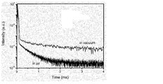
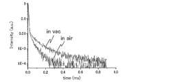
- FIG. 4 is a graph showing PL transient attenuation of an organic photoluminescence device using the compound 18 of Example 1.
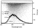
- 2 is a streak image of an organic photoluminescence device using the compound 18 of Example 1.
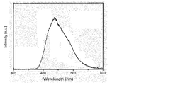
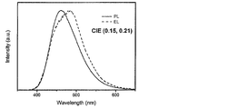
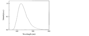
- 2 is an emission spectrum of an organic electroluminescence device using the compound 18 of Example 2.
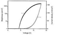
- 6 is a graph showing current density-voltage-luminance characteristics of an organic electroluminescence device using the compound 18 of Example 2.
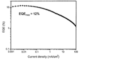
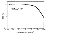
- 6 is a graph showing current density-external quantum efficiency characteristics of an organic electroluminescence device using the compound 18 of Example 2.
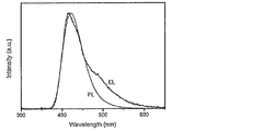
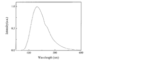
- 2 is an emission spectrum of an organic photoluminescence device using the compound 1 of Example 3.
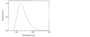
- 3 is an emission spectrum of an organic photoluminescence device using the compound 3 of Example 3.
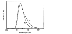
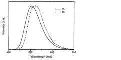
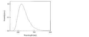
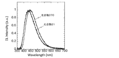
- 2 is an emission spectrum of an organic photoluminescence device using the compound 21 of Example 3. It is an emission spectrum of the organic photoluminescent element using the compound 22 of Example 3, and the organic electroluminescent element of Example 6.
- 2 is an emission spectrum of an organic photoluminescence device using the compound 355 of Example 3 and an organic electroluminescence device of Example 6.
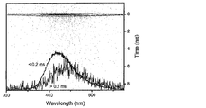
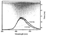
- 3 is a streak image of an organic photoluminescence device using the compound 1 of Example 3.
- 2 is a streak image of an organic photoluminescence device using the compound 3 of Example 3.
- 3 is a streak image of an organic photoluminescence device using the compound 21 of Example 3.
- 3 is a streak image of an organic photoluminescence device using the compound 22 of Example 3.
- FIG. 3 is a streak image of an organic photoluminescence device using the compound 230 of Example 3.
- 3 is a streak image of an organic photoluminescence device using the compound 355 of Example 3.
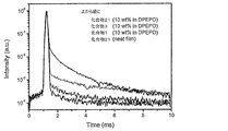
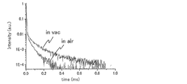
- FIG. 3 shows PL transient attenuation of an organic photoluminescence device using Compound 1, Compound 3 and Compound 21 of Example 3.
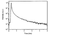
- FIG. 3 shows PL transient attenuation of an organic photoluminescence device using the compound 230 of Example 3.
- FIG. 2 is an emission spectrum of an organic electroluminescence device using the compound 21 of Example 4.
- 6 is a graph showing current density-voltage-luminance characteristics of an organic electroluminescence device using the compound 21 of Example 4.
- 6 is a graph showing current density-external quantum efficiency characteristics of an organic electroluminescence device using the compound 21 of Example 4.
- 6 is a graph showing current density-external quantum efficiency characteristics of an organic electroluminescence device using Compound 1 and Compound 3 of Example 5.
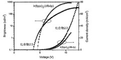
- 6 is a graph showing the current density-external quantum efficiency characteristics of an organic electroluminescence device using the compound 21 of Example 5 and Ir (fppz) 2 (dfbdp).
- 6 is a graph showing current density-voltage-luminance characteristics of an organic electroluminescence device using the compound 21 of Example 5 and Ir (fppz) 2 (dfbdp).
- 6 is a graph showing current density-external quantum efficiency characteristics of an organic electroluminescence device using the compound 22 of Example 6.
- 6 is a graph showing current density-voltage-luminance characteristics of an organic electroluminescence device using the compound 22 of Example 6.
- 10 is a graph showing current density-external quantum efficiency characteristics of an organic electroluminescence device using the compound 355 of Example 7.
- 6 is a graph showing current density-voltage-luminance characteristics of an organic electroluminescence device using the compound 355 of Example 7.
- 6 is an emission spectrum of an organic photoluminescence device using the compound 364 of Example 8.
- 7 is an emission spectrum of an organic photoluminescence device using the compound 367 of Example 8.
- 10 is an emission spectrum of an organic photoluminescence device using the compound 370 of Example 8.
- 7 is an emission spectrum of an organic photoluminescence device using the compound 373 of Example 8.
- 7 is an emission spectrum of an organic photoluminescence device using the compound 376 of Example 8.
- 10 is a graph showing PL transient attenuation of an organic photoluminescence device using the compound 364 of Example 9. It is a graph which shows PL transient attenuation
- 10 is a graph showing PL transient attenuation of an organic photoluminescence device using the compound 370 of Example 9. It is a graph which shows PL transient attenuation
- 10 is a graph showing PL transient attenuation of an organic photoluminescence device using the compound 376 of Example 9. It is an emission spectrum of the organic electroluminescent element using the compound 21 and the compound 370 of Example 10.
- 6 is a graph showing current density-external quantum efficiency characteristics of an organic electroluminescence device using the compound 21 and the compound 370 of Example 10. It is a graph which shows PL transient attenuation
- 6 is an emission spectrum of an organic photoluminescence device using the compound 453 of Example 12.
- 6 is a streak image of an organic photoluminescence device using the compound 453 of Example 12.
- FIG. It is an emission spectrum of the organic electroluminescent element using the compound 453 of Example 13.
- 14 is a graph showing current density-external quantum efficiency characteristics of an organic electroluminescence device using the compound 453 of Example 13.
- a numerical range represented by using “to” means a range including numerical values described before and after “to” as a lower limit value and an upper limit value.
- the luminescent material of the present invention is characterized by comprising a compound represented by the following general formula (1).
- the organic light-emitting device of the present invention is characterized by containing a compound represented by the following general formula (1) as a light-emitting material of the light-emitting layer. Therefore, first, the compound represented by the general formula (1) will be described.
- R 1 to R 10 each independently represents a hydrogen atom or a substituent. However, not all of R 1 to R 10 are hydrogen atoms.
- the number of substituents is preferably 1 to 8, and more preferably 1 to 6.
- the number of substituents may be 1 to 4, 2 to 6, or 2 to 4.
- the number of substituents may be the same as or different from each other. When they are the same, there is an advantage that synthesis is easy.
- any of R 2 to R 4 and R 7 to R 9 is preferably a substituent, and the other is preferably a hydrogen atom.
- at least one of R 2 to R 4 and R 7 to R 9 preferably two or more are used as a substituent, or at least one of R 2 to R 4 and R 7 to R 9 At least one of them as a substituent, at least one of R 2 , R 4 , R 7 and R 9 , preferably two or more as a substituent, and R 2 and R 4
- R 2 to R 4 and R 7 to R 9 are substituents and the others are hydrogen atoms, or all of R 2 , R 4 , R 7 and R 9 are substituents.
- the other is a hydrogen atom
- R 2 and R 4 are substituents and the other is a hydrogen atom
- R 2 is a substituent and the other is a hydrogen atom
- R 3 is a substituent and the others are hydrogen atoms
- R 1 to R 10 can take include, for example, a hydroxy group, a halogen atom, a cyano group, an alkyl group having 1 to 20 carbon atoms, an alkoxy group having 1 to 20 carbon atoms, an alkylthio group having 1 to 20 carbon atoms, carbon An alkyl-substituted amino group having 1 to 20 carbon atoms, an acyl group having 2 to 20 carbon atoms, an aryl group having 6 to 40 carbon atoms, a heteroaryl group having 3 to 40 carbon atoms, a diarylamino group having 12 to 40 carbon atoms, and a carbon number A substituted or unsubstituted carbazolyl group having 12 to 40 carbon atoms, an alkenyl group having 2 to 10 carbon atoms, an alkynyl group having 2 to 10 carbon atoms, an alkoxycarbonyl group having 2 to 10 carbon atoms, an alkylsulfonyl group having 1 to
- substituents are a halogen atom, a cyano group, a substituted or unsubstituted alkyl group having 1 to 20 carbon atoms, an alkoxy group having 1 to 20 carbon atoms, a substituted or unsubstituted aryl group having 6 to 40 carbon atoms, carbon A substituted or unsubstituted heteroaryl group having 3 to 40 carbon atoms, a substituted or unsubstituted diarylamino group having 12 to 40 carbon atoms, and a substituted or unsubstituted carbazolyl group having 12 to 40 carbon atoms.
- substituents are a fluorine atom, a chlorine atom, a cyano group, a substituted or unsubstituted alkyl group having 1 to 10 carbon atoms, a substituted or unsubstituted alkoxy group having 1 to 10 carbon atoms, and a substituted group having 1 to 10 carbon atoms.
- an unsubstituted dialkylamino group, a substituted or unsubstituted aryl group having 6 to 15 carbon atoms, and a substituted or unsubstituted heteroaryl group having 3 to 12 carbon atoms For example, it can be selected from a substituted or unsubstituted alkyl group having 1 to 6 carbon atoms and a substituted or unsubstituted alkoxy group having 1 to 6 carbon atoms.
- the alkyl group in the present specification may be linear, branched or cyclic, and more preferably has 1 to 6 carbon atoms. Specific examples thereof include a methyl group, an ethyl group, a propyl group, and butyl. Group, t-butyl group, pentyl group, hexyl group and isopropyl group.
- the alkoxy group may be linear, branched or cyclic, and more preferably has 1 to 6 carbon atoms, and specific examples include methoxy group, ethoxy group, propoxy group, butoxy group, t-butoxy group. A group, a pentyloxy group, a hexyloxy group, and an isopropyloxy group.
- the two alkyl groups of the dialkylamino group may be the same or different from each other, but are preferably the same.
- the two alkyl groups of the dialkylamino group may each independently be linear, branched or cyclic, and more preferably have 1 to 6 carbon atoms. Specific examples include a methyl group, an ethyl group, Examples thereof include a propyl group, a butyl group, a pentyl group, a hexyl group, and an isopropyl group.
- the aryl group may be a single ring or a fused ring, and specific examples thereof include a phenyl group and a naphthyl group.
- the heteroaryl group may be a monocyclic ring or a fused ring, and specific examples include a pyridyl group, a pyridazyl group, a pyrimidyl group, a triazyl group, a triazolyl group, and a benzotriazolyl group.
- These heteroaryl groups may be a group bonded through a hetero atom or a group bonded through a carbon atom constituting a heteroaryl ring.
- R 1 and R 2 , R 2 and R 3 , R 3 and R 4 , R 4 and R 5 , R 5 and R 6 , R 6 and R 7 , R 7 and R 8 , R 8 and R 9 , and R 9 and R 10 may be bonded to each other to form a cyclic structure. Only one of these may form a cyclic structure, or two or more may form a cyclic structure. When a cyclic structure is formed, the cyclic structure is any one of R 2 and R 3 , R 3 and R 4 , R 5 and R 6 , R 7 and R 8 , R 8 and R 9. It is preferable to be formed as described above.
- R 5 and R 6 When R 5 and R 6 are bonded to each other, it is preferably a single bond or a connecting group having 1 or 2 connecting chain constituent atoms to form a 5- to 7-membered ring, respectively.
- Examples of the connecting group having 1 or 2 connecting chain constituent atoms include a methylene group, an ethylene group, and an ethenylene group.
- the cyclic structure formed by bonding R 2 and R 3 , R 3 and R 4 , R 7 and R 8 , R 8 and R 9 may include a hetero atom in the ring skeleton.
- the hetero atom here is preferably selected from the group consisting of a nitrogen atom, an oxygen atom and a sulfur atom.
- Examples of cyclic structures formed include benzene ring, naphthalene ring, pyridine ring, pyridazine ring, pyrimidine ring, pyrazine ring, pyrrole ring, imidazole ring, pyrazole ring, triazole ring, imidazoline ring, oxazole ring, isoxazole ring, thiazole Ring, isothiazole ring, cyclohexadiene ring, cyclohexene ring, cyclopentaene ring, cycloheptatriene ring, cycloheptadiene ring, cycloheptaene ring and the like, and a benzene ring, a pyridine ring, and a cyclohexene ring are more preferable. .
- the formed cyclic structure may be a fused ring.
- At least one of R 1 to R 10 is a substituted or unsubstituted aryl group, a substituted or unsubstituted diarylamino group, or a substituted or unsubstituted 9-carbazolyl group.
- Preferred is an embodiment in which at least one of R 1 to R 10 is a substituted or unsubstituted diarylamino group, or a substituted or unsubstituted 9-carbazolyl group.
- a substituted or unsubstituted diarylamino group and a substituted or unsubstituted 9-carbazolyl group may be mixed, and a substituted or unsubstituted aryl group, substituted or unsubstituted
- a substituted diarylamino group may be mixed, a substituted or unsubstituted aryl group and a substituted or unsubstituted 9-carbazolyl group may be mixed, a substituted or unsubstituted aryl group,
- Three types of an unsubstituted diarylamino group and a substituted or unsubstituted 9-carbazolyl group may be mixed.
- the two aryl groups of the diarylamino group referred to here may be linked to each other by a linking group.
- At least one of R 1 to R 10 is preferably a group having a structure represented by the following general formula (6).
- R 11 to R 20 each independently represents a hydrogen atom or a substituent.
- R 15 and R 16 may be bonded to each other to form a single bond or a divalent linking group.
- the divalent linking group include —O—, —S—, —N (R) — and the like. Of these, —O— and —S— are preferable.
- R in —N (R) — represents a substituted or unsubstituted alkyl group or a substituted or unsubstituted aryl group, preferably a substituted or unsubstituted alkyl group having 1 to 10 carbon atoms, or 6 to 14 carbon atoms.
- a substituted or unsubstituted aryl group more preferably a substituted or unsubstituted alkyl group having 1 to 6 carbon atoms, a substituted or unsubstituted aryl group having 6 to 10 carbon atoms, and still more preferably a carbon number 1 to 3 substituted or unsubstituted alkyl groups.
- R 11 and R 12 , R 12 and R 13 , R 13 and R 14 , R 14 and R 15 , R 16 and R 17 , R 17 and R 18 , R 18 and R 19 , R 19 and R 20 are respectively They may be bonded together to form a ring structure.
- R 11 to R 20 in the general formula (6) refer to the explanations and preferred ranges of the substituents and cyclic structures in the general formula (1). it can.
- At least one of R 1 to R 10 in the general formula (1) is preferably a group having a structure represented by the following general formula (7).
- R 21 to R 30 each independently represents a hydrogen atom or a substituent.
- R 21 and R 22 , R 22 and R 23 , R 23 and R 24 , R 24 and R 25 , R 26 and R 27 , R 27 and R 28 , R 28 and R 29 , R 29 and R 30 are respectively They may be bonded together to form a ring structure.
- R 21 to R 20 in general formula (7) refer to the explanation and preferred ranges of substituents and cyclic structures in general formula (1) above. it can.
- At least one of R 1 to R 10 in the general formula (1) is preferably a group having a structure represented by the following general formula (8).
- R 31 to R 34 and R 37 to R 40 each independently represents a hydrogen atom or a substituent.
- R 31 and R 32 , R 32 and R 33 , R 33 and R 34 , R 37 and R 38 , R 38 and R 39 , and R 39 and R 40 may be bonded to each other to form a cyclic structure.
- the explanations and preferred ranges of the substituents and cyclic structures that can be taken by R 31 to R 34 and R 37 to R 40 in the general formula (8) the explanations and preferred ranges of the substituents and the cyclic structures in the general formula (1) are preferable. You can refer to the range.
- At least one of R 1 to R 10 in the general formula (1) is preferably a group having a structure represented by the following general formula (9).
- R 41 to R 50 each independently represents a hydrogen atom or a substituent.
- R 41 and R 42 , R 42 and R 43 , R 43 and R 44 , R 47 and R 48 , R 48 and R 49 , R 49 and R 50 may be bonded to each other to form a cyclic structure.
- R 41 to R 50 refer to the explanations and preferred ranges of the substituents and cyclic structures in the general formula (1). it can.
- R 45 and R 46 in the general formula (9) can take are a substituted or unsubstituted alkyl group and a substituted or unsubstituted aryl group.
- a substituted or unsubstituted alkyl group is preferable.
- the alkyl group preferably has 1 to 15 carbon atoms, more preferably 1 to 10 carbon atoms, and still more preferably 1 to 6 carbon atoms.
- R 1 - R 10 is has a structure represented by any one of the above general formula (7) to (9), the other of R 1 - R 10
- An embodiment in which at least one has another structure represented by the general formulas (7) to (9) can also be mentioned as a preferred embodiment.
- the compound represented by the general formula (1) preferably has a structure represented by the following general formula (2).
- R 1 , R 2 , R 4 to R 7 , R 9 , and R 10 each independently represent a hydrogen atom or a substituent.
- Z 3 and Z 8 each independently represent a hydrogen atom, a substituted or unsubstituted aryl group, a substituted or unsubstituted diarylamino group, or a substituted or unsubstituted 9-carbazolyl group, both of which are hydrogen atoms There is nothing.
- Z 3 and Z 4 are preferably each independently a substituted or unsubstituted diarylamino group, or a substituted or unsubstituted 9-carbazolyl group, represented by the above general formula (7) or general formula (8).
- R 1 and R 2 , R 4 and R 5 , R 5 and R 6 , R 6 and R 7 , and R 9 and R 10 may be bonded to each other to form a cyclic structure.
- R 1 , R 2 , R 4 to R 7 , R 9 , R 10 are preferably each independently a hydrogen atom, a substituted or unsubstituted alkyl group, or a substituted or unsubstituted alkoxy group, and all hydrogen atoms It is also preferable.
- the compound represented by the general formula (1) preferably has a structure represented by the following general formula (3).
- R 1 , R 3 , R 5 to R 7 , R 9 , and R 10 each independently represent a hydrogen atom or a substituent.
- Z 2, Z 4 and Z 8 are each independently a hydrogen atom, a substituted or unsubstituted aryl group, a substituted or unsubstituted diarylamino group or a substituted or unsubstituted 9-carbazolyl group, all hydrogen atoms Never.
- Z 2 , Z 4 and Z 8 are preferably each independently a substituted or unsubstituted diarylamino group, or a substituted or unsubstituted 9-carbazolyl group.
- R 5 and R 6 , R 6 and R 7 , R 9 and R 10 may be bonded to each other to form a cyclic structure.
- R 1 , R 3 , R 5 to R 7 , R 9 and R 10 are each independently preferably a hydrogen atom, a substituted or unsubstituted alkyl group, or a substituted or unsubstituted alkoxy group, and all are hydrogen atoms. It is also preferable.
- the compound represented by the general formula (1) has a structure represented by the following general formula (4).
- R 1 , R 3 , R 5 , R 6 , R 8 and R 10 each independently represent a hydrogen atom or a substituent.
- R 5 and R 6 may combine with each other to form a cyclic structure.
- Z 2 , Z 4 , Z 7 and Z 9 each independently represent a hydrogen atom, a substituted or unsubstituted aryl group, a substituted or unsubstituted diarylamino group, or a substituted or unsubstituted 9-carbazolyl group, substituted or An unsubstituted diarylamino group or a substituted or unsubstituted 9-carbazolyl group is preferable, and a group represented by the general formula (7) or the general formula (8) is more preferable.
- Z 2 , Z 4 , Z 7 and Z 9 are hydrogen atoms.
- R 1 , R 3 , R 5 , R 6 , R 8 and R 10 are each independently preferably a hydrogen atom, a substituted or unsubstituted alkyl group, or a substituted or unsubstituted alkoxy group, and all are hydrogen atoms. It is also preferable.
- the compound represented by the general formula (1) has a structure represented by the following general formula (5).
- R 2 , R 3 , R 4 , R 5 , R 6 , R 7 , R 8 , R 9 each independently represents a hydrogen atom or a substituent.
- R 2 and R 3 , R 3 and R 4 , R 4 and R 5 , R 5 and R 6 , R 6 and R 7 , R 7 and R 8 , R 8 and R 9 are bonded to each other to form a cyclic structure May be formed.
- Z 1 and Z 10 each independently represents a hydrogen atom, a substituted or unsubstituted aryl group, a substituted or unsubstituted diarylamino group, or a substituted or unsubstituted 9-carbazolyl group, and a substituted or unsubstituted diarylamino group Or a substituted or unsubstituted 9-carbazolyl group, more preferably a group represented by the above general formula (7) or general formula (8).
- Z 1 and Z 10 are not both hydrogen atoms.
- R 2 , R 3 , R 4 , R 5 , R 6 , R 7 , R 8 and R 9 are each independently a hydrogen atom, a substituted or unsubstituted alkyl group, or a substituted or unsubstituted alkoxy group. It is also preferable that all are hydrogen atoms.
- the molecular weight of the compound represented by the general formula (1) is, for example, 1500 or less when the organic layer containing the compound represented by the general formula (1) is intended to be formed by vapor deposition. Preferably, it is preferably 1200 or less, more preferably 1000 or less, and even more preferably 800 or less. The lower limit of the molecular weight is the molecular weight of the compound 101.
- the compound represented by the general formula (1) may be formed by a coating method regardless of the molecular weight. If a coating method is used, a film can be formed even with a compound having a relatively large molecular weight.
- a compound containing a plurality of structures represented by the general formula (1) in the molecule may be used for the light emitting layer of the organic light emitting device.
- a polymer obtained by polymerizing a polymerizable monomer having a structure represented by the general formula (1) for a light emitting layer of an organic light emitting device.
- a monomer having a polymerizable functional group in any one of R 1 to R 10 of the general formula (1) and polymerizing it alone or copolymerizing with other monomers, It is considered that a polymer having a repeating unit is obtained and the polymer is used for a light emitting layer of an organic light emitting device.
- dimers and trimers are obtained by coupling compounds having a structure represented by the general formula (1) and used in the light emitting layer of the organic light emitting device.
- any one of R 1 to R 10 in the general formula (1) is represented by the following general formula (10) or (11). The thing which is a structure represented can be mentioned.
- L 1 and L 2 each represent a linking group.
- the linking group preferably has 0 to 20 carbon atoms, more preferably 1 to 15 carbon atoms, and still more preferably 2 to 10 carbon atoms. And preferably has a structure represented by - linking group -X 11 -L 11.
- X 11 represents an oxygen atom or a sulfur atom, and is preferably an oxygen atom.
- L 11 represents a linking group, and is preferably a substituted or unsubstituted alkylene group, or a substituted or unsubstituted arylene group, and is a substituted or unsubstituted alkylene group having 1 to 10 carbon atoms, or a substituted or unsubstituted group A phenylene group is more preferable.
- R 101 , R 102 , R 103 and R 104 each independently represent a substituent.
- it is a substituted or unsubstituted alkyl group having 1 to 6 carbon atoms, a substituted or unsubstituted alkoxy group having 1 to 6 carbon atoms, or a halogen atom, more preferably an unsubstituted alkyl group having 1 to 3 carbon atoms.
- An unsubstituted alkoxy group having 1 to 3 carbon atoms, a fluorine atom, and a chlorine atom and more preferably an unsubstituted alkyl group having 1 to 3 carbon atoms and an unsubstituted alkoxy group having 1 to 3 carbon atoms.
- R 1 to R 10 in the general formula (1) is represented by the following formulas (12) to (15).
- R 1 to R 10 may be represented by the following formulas (12) to (15), but preferably one of R 1 to R 10 is represented by the following formulas (12) to (15 ).
- At least one of R 1 to R 10 in the general formula (1) is made into a hydroxy group, and the following compounds are reacted using it as a linker. It can be synthesized by introducing a polymerizable group and polymerizing the polymerizable group.
- the polymer containing the structure represented by the general formula (1) in the molecule may be a polymer composed only of repeating units having the structure represented by the general formula (1), or other structures may be used. It may be a polymer containing repeating units.
- the repeating unit having a structure represented by the general formula (1) contained in the polymer may be a single type or two or more types. Examples of the repeating unit not having the structure represented by the general formula (1) include those derived from monomers used in ordinary copolymerization. Examples thereof include a repeating unit derived from a monomer having an ethylenically unsaturated bond such as ethylene and styrene.
- the method for synthesizing the compound represented by the general formula (1) is not particularly limited.
- the synthesis of the compound represented by the general formula (1) can be performed by appropriately combining known synthesis methods and conditions. For example, it can be synthesized by reacting bis (halogenated phenyl) sulfone with diphenylamine. At this time, for example, the reaction can proceed by heating in the presence of NaH.
- a compound of the general formula (1) having a desired substituent can be synthesized.
- the compound represented by the general formula (1) is preferably a thermally activated delayed fluorescent material.
- a delayed fluorescent material When used as a delayed fluorescent material in the light emitting layer of an organic electroluminescence element, high luminous efficiency can be achieved at a lower cost than in the past.
- a phosphorescent material it is necessary to use a rare metal such as Ir or Pt. If the delayed fluorescent material is used, such an expensive material is not required, and therefore, an organic electroluminescence element having high luminous efficiency can be provided at low cost.
- the compound represented by the general formula (1) of the present invention is useful as a light emitting material of an organic light emitting device. For this reason, the compound represented by General formula (1) of this invention can be effectively used as a luminescent material for the light emitting layer of an organic light emitting element.
- the compound represented by the general formula (1) includes a delayed fluorescent material (delayed phosphor) that emits delayed fluorescence. That is, the present invention relates to a delayed phosphor having a structure represented by the general formula (1), an invention using a compound represented by the general formula (1) as a delayed phosphor, and a general formula (1).
- An invention of a method for emitting delayed fluorescence using the represented compound is also provided.
- An organic light emitting device using such a compound as a light emitting material emits delayed fluorescence and has a feature of high luminous efficiency. The principle will be described below by taking an organic electroluminescence element as an example.
- the organic electroluminescence element carriers are injected into the light emitting material from both positive and negative electrodes to generate an excited light emitting material and emit light.
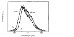
- 25% of the generated excitons are excited to the excited singlet state, and the remaining 75% are excited to the excited triplet state. Therefore, the use efficiency of energy is higher when phosphorescence, which is light emission from an excited triplet state, is used.
- the excited triplet state has a long lifetime, energy saturation occurs due to saturation of the excited state and interaction with excitons in the excited triplet state, and in general, the quantum yield of phosphorescence is often not high.
- delayed fluorescent materials after energy transition to an excited triplet state due to intersystem crossing, etc., are then crossed back to an excited singlet state due to triplet-triplet annihilation or absorption of thermal energy, and emit fluorescence.
- a thermally activated delayed fluorescent material by absorption of thermal energy is particularly useful.
- excitons in the excited singlet state emit fluorescence as usual.
- excitons in the excited triplet state absorb heat generated by the device and cross between the excited singlets to emit fluorescence.
- the light is emitted from the excited singlet, the light is emitted at the same wavelength as the fluorescence, but the lifetime of light generated (emission life) due to the reverse intersystem crossing from the excited triplet state to the excited singlet state is normal. Since the fluorescence becomes longer than the fluorescence and phosphorescence, it is observed as fluorescence delayed from these. This can be defined as delayed fluorescence. If such a heat-activated exciton transfer mechanism is used, the ratio of the compound in an excited singlet state, which normally generated only 25%, is increased to 25% or more by absorbing thermal energy after carrier injection. It can be raised.
- the heat of the device will sufficiently cause intersystem crossing from the excited triplet state to the excited singlet state and emit delayed fluorescence. Efficiency can be improved dramatically.
- organic light-emitting devices such as an organic photoluminescence device (organic PL device) and an organic electroluminescence device (organic EL device) can be provided.
- the organic photoluminescence element has a structure in which at least a light emitting layer is formed on a substrate.
- the organic electroluminescence element has a structure in which an organic layer is formed at least between an anode, a cathode, and an anode and a cathode.
- the organic layer includes at least a light emitting layer, and may consist of only the light emitting layer, or may have one or more organic layers in addition to the light emitting layer.
- Examples of such other organic layers include a hole transport layer, a hole injection layer, an electron blocking layer, a hole blocking layer, an electron injection layer, an electron transport layer, and an exciton blocking layer.
- the hole transport layer may be a hole injection / transport layer having a hole injection function
- the electron transport layer may be an electron injection / transport layer having an electron injection function.
- FIG. 1 A specific example of the structure of an organic electroluminescence element is shown in FIG. In FIG. 1, 1 is a substrate, 2 is an anode, 3 is a hole injection layer, 4 is a hole transport layer, 5 is a light emitting layer, 6 is an electron transport layer, and 7 is a cathode. Below, each member and each layer of an organic electroluminescent element are demonstrated. In addition, description of a board
- the organic electroluminescence device of the present invention is preferably supported on a substrate.
- the substrate is not particularly limited and may be any substrate conventionally used for organic electroluminescence elements.
- a substrate made of glass, transparent plastic, quartz, silicon, or the like can be used.
- an electrode material made of a metal, an alloy, an electrically conductive compound, or a mixture thereof having a high work function (4 eV or more) is preferably used.
- electrode materials include metals such as Au, and conductive transparent materials such as CuI, indium tin oxide (ITO), SnO 2 and ZnO.
- conductive transparent materials such as CuI, indium tin oxide (ITO), SnO 2 and ZnO.
- an amorphous material such as IDIXO (In 2 O 3 —ZnO) capable of forming a transparent conductive film may be used.
- a thin film may be formed by vapor deposition or sputtering of these electrode materials, and a pattern of a desired shape may be formed by photolithography, or when pattern accuracy is not so high (about 100 ⁇ m or more) ), A pattern may be formed through a mask having a desired shape at the time of vapor deposition or sputtering of the electrode material.
- wet film-forming methods such as a printing system and a coating system, can also be used.
- the transmittance be greater than 10%, and the sheet resistance as the anode is preferably several hundred ⁇ / ⁇ or less.
- the film thickness depends on the material, it is usually selected in the range of 10 to 1000 nm, preferably 10 to 200 nm.
- cathode a material having a low work function (4 eV or less) metal (referred to as an electron injecting metal), an alloy, an electrically conductive compound, and a mixture thereof as an electrode material is used.
- electrode materials include sodium, sodium-potassium alloy, magnesium, lithium, magnesium / copper mixture, magnesium / silver mixture, magnesium / aluminum mixture, magnesium / indium mixture, aluminum / aluminum oxide (Al 2 O 3 ) Mixtures, indium, lithium / aluminum mixtures, rare earth metals and the like.
- a mixture of an electron injecting metal and a second metal which is a stable metal having a larger work function value than this for example, a magnesium / silver mixture, Magnesium / aluminum mixtures, magnesium / indium mixtures, aluminum / aluminum oxide (Al 2 O 3 ) mixtures, lithium / aluminum mixtures, aluminum and the like are preferred.
- the cathode can be produced by forming a thin film of these electrode materials by a method such as vapor deposition or sputtering.
- the sheet resistance as the cathode is preferably several hundred ⁇ / ⁇ or less, and the film thickness is usually selected in the range of 10 nm to 5 ⁇ m, preferably 50 to 200 nm.
- the emission luminance is advantageously improved.
- a transparent or semi-transparent cathode can be produced. By applying this, an element in which both the anode and the cathode are transparent is used. Can be produced.
- the light emitting layer is a layer that emits light after excitons are generated by recombination of holes and electrons injected from each of the anode and the cathode, and the light emitting material may be used alone for the light emitting layer. , Preferably including a luminescent material and a host material.
- a luminescent material the 1 type (s) or 2 or more types chosen from the compound group of this invention represented by General formula (1) can be used.
- a host material in addition to the light emitting material in the light emitting layer.
- the host material an organic compound having at least one of excited singlet energy and excited triplet energy higher than that of the light emitting material of the present invention can be used.
- singlet excitons and triplet excitons generated in the light emitting material of the present invention can be confined in the molecules of the light emitting material of the present invention, and the light emission efficiency can be sufficiently extracted.
- high luminous efficiency can be obtained, so that host materials that can achieve high luminous efficiency are particularly limited. And can be used in the present invention.
- the organic light emitting device or organic electroluminescent device of the present invention light emission is generated from the light emitting material of the present invention contained in the light emitting layer. This emission includes both fluorescence and delayed fluorescence. However, light emission from the host material may be partly or partly emitted.
- the amount of the compound of the present invention, which is a light emitting material is preferably 0.1% by weight or more, more preferably 1% by weight or more, and 50% or more. It is preferably no greater than wt%, more preferably no greater than 20 wt%, and even more preferably no greater than 10 wt%.
- the host material in the light-emitting layer is preferably an organic compound that has a hole transporting ability and an electron transporting ability, prevents the emission of longer wavelengths, and has a high glass transition temperature.
- the injection layer is a layer provided between the electrode and the organic layer for lowering the driving voltage and improving the luminance of light emission.
- the injection layer can be provided as necessary.
- the blocking layer is a layer that can prevent diffusion of charges (electrons or holes) and / or excitons existing in the light emitting layer to the outside of the light emitting layer.
- the electron blocking layer can be disposed between the light emitting layer and the hole transport layer and blocks electrons from passing through the light emitting layer toward the hole transport layer.
- a hole blocking layer can be disposed between the light emitting layer and the electron transporting layer to prevent holes from passing through the light emitting layer toward the electron transporting layer.
- the blocking layer can also be used to block excitons from diffusing outside the light emitting layer. That is, each of the electron blocking layer and the hole blocking layer can also function as an exciton blocking layer.
- the term “electron blocking layer” or “exciton blocking layer” as used herein is used in the sense of including a layer having the functions of an electron blocking layer and an exciton blocking layer in one layer.
- the hole blocking layer has a function of an electron transport layer in a broad sense.
- the hole blocking layer has a role of blocking holes from reaching the electron transport layer while transporting electrons, thereby improving the recombination probability of electrons and holes in the light emitting layer.
- the material for the hole blocking layer the material for the electron transport layer described later can be used as necessary.
- the electron blocking layer has a function of transporting holes in a broad sense.
- the electron blocking layer has a role to block electrons from reaching the hole transport layer while transporting holes, thereby improving the probability of recombination of electrons and holes in the light emitting layer. .
- the exciton blocking layer is a layer for preventing excitons generated by recombination of holes and electrons in the light emitting layer from diffusing into the charge transport layer. It becomes possible to efficiently confine in the light emitting layer, and the light emission efficiency of the device can be improved.
- the exciton blocking layer can be inserted on either the anode side or the cathode side adjacent to the light emitting layer, or both can be inserted simultaneously.
- the layer when the exciton blocking layer is provided on the anode side, the layer can be inserted adjacent to the light emitting layer between the hole transport layer and the light emitting layer, and when inserted on the cathode side, the light emitting layer and the cathode Between the luminescent layer and the light-emitting layer.
- a hole injection layer, an electron blocking layer, or the like can be provided between the anode and the exciton blocking layer adjacent to the anode side of the light emitting layer, and the excitation adjacent to the cathode and the cathode side of the light emitting layer can be provided.
- an electron injection layer, an electron transport layer, a hole blocking layer, and the like can be provided.
- the blocking layer is disposed, at least one of the excited singlet energy and the excited triplet energy of the material used as the blocking layer is preferably higher than the excited singlet energy and the excited triplet energy of the light emitting material.
- the hole transport layer is made of a hole transport material having a function of transporting holes, and the hole transport layer can be provided as a single layer or a plurality of layers.
- the hole transport material has any one of hole injection or transport and electron barrier properties, and may be either organic or inorganic.
- hole transport materials that can be used include, for example, triazole derivatives, oxadiazole derivatives, imidazole derivatives, carbazole derivatives, indolocarbazole derivatives, polyarylalkane derivatives, pyrazoline derivatives and pyrazolone derivatives, phenylenediamine derivatives, arylamine derivatives, Examples include amino-substituted chalcone derivatives, oxazole derivatives, styrylanthracene derivatives, fluorenone derivatives, hydrazone derivatives, stilbene derivatives, silazane derivatives, aniline copolymers, and conductive polymer oligomers, particularly thiophene oligomers.
- An aromatic tertiary amine compound and an styrylamine compound are preferably used, and an aromatic tertiary amine compound is more preferably used.
- the electron transport layer is made of a material having a function of transporting electrons, and the electron transport layer can be provided as a single layer or a plurality of layers.
- the electron transport material (which may also serve as a hole blocking material) may have a function of transmitting electrons injected from the cathode to the light emitting layer.
- Examples of the electron transport layer that can be used include nitro-substituted fluorene derivatives, diphenylquinone derivatives, thiopyran dioxide oxide derivatives, carbodiimides, fluorenylidenemethane derivatives, anthraquinodimethane and anthrone derivatives, oxadiazole derivatives, and the like.
- a thiadiazole derivative in which the oxygen atom of the oxadiazole ring is substituted with a sulfur atom, and a quinoxaline derivative having a quinoxaline ring known as an electron withdrawing group can also be used as an electron transport material.
- a polymer material in which these materials are introduced into a polymer chain or these materials are used as a polymer main chain can also be used.
- the compound represented by the general formula (1) may be used not only for the light emitting layer but also for layers other than the light emitting layer.
- the compound represented by General formula (1) used for a light emitting layer and the compound represented by General formula (1) used for layers other than a light emitting layer may be same or different.
- the compound represented by the general formula (1) may be used for the injection layer, blocking layer, hole blocking layer, electron blocking layer, exciton blocking layer, hole transporting layer, electron transporting layer, and the like. .
- the method for forming these layers is not particularly limited, and the layer may be formed by either a dry process or a wet process.
- the preferable material which can be used for an organic electroluminescent element is illustrated concretely.
- the material that can be used in the present invention is not limited to the following exemplary compounds.
- R, R ′, and R 1 to R 10 in the structural formulas of the following exemplary compounds each independently represent a hydrogen atom or a substituent.
- X represents a carbon atom or a hetero atom forming a ring skeleton
- n represents an integer of 3 to 5
- Y represents a substituent
- m represents an integer of 0 or more.
- the organic electroluminescence device produced by the above-described method emits light by applying an electric field between the anode and the cathode of the obtained device. At this time, if the light is emitted by excited singlet energy, light having a wavelength corresponding to the energy level is confirmed as fluorescence emission and delayed fluorescence emission. In addition, in the case of light emission by excited triplet energy, a wavelength corresponding to the energy level is confirmed as phosphorescence. Since normal fluorescence has a shorter fluorescence lifetime than delayed fluorescence, the emission lifetime can be distinguished from fluorescence and delayed fluorescence.
- the excited triplet energy is unstable and is converted into heat and the like, and the lifetime is short and it is immediately deactivated.
- the excited triplet energy of a normal organic compound it can be measured by observing light emission under extremely low temperature conditions.
- the organic electroluminescence element of the present invention can be applied to any of a single element, an element having a structure arranged in an array, and a structure in which an anode and a cathode are arranged in an XY matrix. According to the present invention, an organic light emitting device with greatly improved light emission efficiency can be obtained by containing the compound represented by the general formula (1) in the light emitting layer.
- the organic light emitting device such as the organic electroluminescence device of the present invention can be further applied to various uses. For example, it is possible to produce an organic electroluminescence display device using the organic electroluminescence element of the present invention.
- organic electroluminescence device of the present invention can be applied to organic electroluminescence illumination and backlights that are in great demand.
- Example 1 an organic photoluminescence device having a light-emitting layer composed of the compound 18 and a host material was produced, and the characteristics were evaluated.
- Compound 18 and DPEPO were deposited from different deposition sources on a silicon substrate by vacuum deposition under a vacuum degree of 5.0 ⁇ 10 ⁇ 4 Pa, and a thin film having a concentration of compound 18 of 10% by weight was formed to 100 nm.
- An organic photoluminescence device was formed with a thickness of 1 mm.
- a C9920-02 type absolute quantum yield measuring device manufactured by Hamamatsu Photonics Co., Ltd. the emission spectrum from the thin film when irradiated with light of 337 nm with an N 2 laser was characterized at 300K.
- FIG. 3 shows streak images of fluorescence and delayed fluorescence.
- Example 2 an organic electroluminescence device having a light-emitting layer composed of the compound 18 and a host material was produced, and the characteristics were evaluated.
- Each thin film was laminated at a vacuum degree of 5.0 ⁇ 10 ⁇ 4 Pa by a vacuum deposition method on a glass substrate on which an anode made of indium tin oxide (ITO) having a thickness of 100 nm was formed.
- ITO indium tin oxide
- ⁇ -NPD was formed on ITO to a thickness of 40 nm, and mCP was formed thereon to a thickness of 10 nm.
- Compound 18 and DPEPO were co-evaporated from different vapor deposition sources to form a 20 nm thick layer to be a light emitting layer.
- the concentration of the compound 18 was 6.0% by weight.
- DPEPO was formed to a thickness of 10 nm, and TPBI was formed thereon to a thickness of 30 nm.
- lithium fluoride (LiF) was vacuum-deposited by 0.5 nm, and then aluminum (Al) was vapor-deposited to a thickness of 80 nm to form a cathode, whereby an organic electroluminescence element was obtained.
- a semiconductor parameter analyzer manufactured by Agilent Technologies: E5273A
- an optical power meter measuring device manufactured by Newport: 1930C
- an optical spectrometer manufactured by Ocean Optics: USB2000
- the emission spectrum is shown in FIG. 4, the current density-voltage-luminance characteristic is shown in FIG. 5, and the current density-external quantum efficiency characteristic is shown in FIG.
- the organic electroluminescence device using Compound 18 as the light emitting material achieved an external quantum efficiency of 3.2%.
- Example 3 An organic photoluminescence device was produced using Compound 1, Compound 3, Compound 21, Compound 22, Compound 230, and Compound 355 instead of Compound 18 of Example 1, and the characteristics were evaluated. As a result, delayed fluorescence with a long emission lifetime was observed in addition to fluorescence with a short emission lifetime. 7 to 11 show emission spectra. 12 to 17 show streak images, and FIGS. 18 and 19 show PL transient attenuation.
- Example 4 An organic electroluminescence device was produced using the compound 21 instead of the compound 18 of Example 1, and the characteristics were evaluated.
- the emission spectrum is shown in FIG. 20, the current density-voltage-luminance characteristic is shown in FIG. 21, and the current density-external quantum efficiency characteristic is shown in FIG.
- the organic electroluminescence device using Compound 24 as the light emitting material achieved a high external quantum efficiency of 6.7%.
- Example 5 an organic electroluminescence device having a light emitting layer composed of Compound 1 and a host material was produced. Each thin film was laminated at a vacuum degree of 5.0 ⁇ 10 ⁇ 4 Pa by a vacuum deposition method on a glass substrate on which an anode made of indium tin oxide (ITO) having a thickness of 100 nm was formed. First, ⁇ -NPD is formed on ITO with a thickness of 30 nm, and TCTA (4, 4 ′ , 4 ′′ -tris (N-carbazolyl) -triphenylamine) is formed thereon with a thickness of 20 nm.
- ITO indium tin oxide
- CzSi was formed thereon to a thickness of 10 nm, and then Compound 1 and DPEPO were co-evaporated from different evaporation sources to form a 20 nm thick layer as a light emitting layer.
- DPEPO was formed to a thickness of 10 nm
- TPBI was formed to a thickness of 30 nm
- lithium fluoride (LiF) was vacuum-deposited to a thickness of 0.5 nm.
- Al aluminum
- An organic electroluminescence device was produced in the same manner using Compound 3, Compound 21 and Ir (fppz) 2 (dfbdp) instead of Compound 1. About each produced organic electroluminescent element, it measured by the same method as Example 2.
- FIG. 23 and 24 show the current density-external quantum efficiency characteristics.
- FIG. 25 shows current density-voltage-luminance characteristics.
- Example 6 An organic electroluminescence device was prepared in the same manner as in Example 5 except that Compound 22 (10.0% by weight) was used instead of Compound 1 (6.0% by weight) of Example 5, and the characteristics were similarly obtained. evaluated.
- FIG. 10 shows an emission spectrum
- FIG. 26 shows current density-external quantum efficiency characteristics
- FIG. 27 shows current density-voltage-luminance characteristics.
- Example 7 an organic electroluminescence element having a light-emitting layer made of the compound 355 and a host material was fabricated and the characteristics were evaluated. Each thin film was laminated at a vacuum degree of 5.0 ⁇ 10 ⁇ 4 Pa by a vacuum deposition method on a glass substrate on which an anode made of indium tin oxide (ITO) having a thickness of 100 nm was formed. First, ⁇ -NPD was formed on ITO to a thickness of 40 nm, and then compound 355 and CBP were co-deposited from different evaporation sources to form a 20 nm-thick layer as a light emitting layer. At this time, the concentration of the compound 355 was 10.0% by weight.
- ITO indium tin oxide
- TPBI is formed to a thickness of 60 nm
- further lithium fluoride (LiF) is vacuum-deposited to 0.5 nm
- aluminum (Al) is evaporated to a thickness of 80 nm to form a cathode.
- FIG. 11 shows an emission spectrum
- current density-external quantum efficiency characteristics are shown in FIG. 28, and current density-voltage-luminance characteristics are shown in FIG.
- Example 8 In this example, a toluene solution (concentration 10 ⁇ 5 mol / L) of each of the compounds 364, 367, 370, 373, and 376 was prepared, and the fluorescence spectrum was measured. The results are shown in order in FIGS.
- Example 9 an organic photoluminescence element having a light-emitting layer composed of each compound of Compound 364, Compound 367, Compound 370, Compound 373, and Compound 376 and a host material was fabricated, and the characteristics were evaluated.
- the specific procedure was the same as in Example 1, and the compound 364, compound 367, compound 370, compound 373 and compound 376 were used in place of the compound 18 of Example 1.
- the concentration of each compound was 6% by weight.
- delayed fluorescence having a long emission lifetime was observed in addition to fluorescence having a short emission lifetime. Time-resolved spectra obtained in the same manner as in Example 1 are shown in FIGS.
- ⁇ E ST of compound 364, compound 367, and compound 370 energy difference between the lowest excited triplet energy level at 77 ° K and the lowest excited singlet energy level in the light emitting material emitting light at the shortest wavelength
- delayed fluorescence component The following table shows the lifetime ( ⁇ DLAYED ), emission quantum efficiency (PLQE), emission fluorescence efficiency of ordinary fluorescent component (PLQE PROMPT ), lifetime of ordinary fluorescence component ( ⁇ PROMPT ), together with the results when using Compound 21. Shown in
- Example 10 an organic electroluminescence element having a light emitting layer made of each compound 21 and compound 370 and a host material was produced.
- Each thin film was laminated at a vacuum degree of 5.0 ⁇ 10 ⁇ 4 Pa by a vacuum deposition method on a glass substrate on which an anode made of indium tin oxide (ITO) having a thickness of 100 nm was formed.
- ITO indium tin oxide
- ⁇ -NPD was formed on ITO to a thickness of 35 nm
- mCBP was formed thereon to a thickness of 10 nm.
- Compound 21 or Compound 370 and DPEPO were co-evaporated from different evaporation sources to form a layer having a thickness of 15 nm to form a light emitting layer. At this time, the concentration of Compound 21 or Compound 370 was 12.0% by weight.
- DPEPO was formed to a thickness of 10 nm, and TPBI was formed thereon to a thickness of 40 nm.
- lithium fluoride (LiF) was vacuum-deposited by 0.5 nm, and then aluminum (Al) was vapor-deposited to a thickness of 80 nm to form a cathode, whereby an organic electroluminescence element was obtained. About each produced organic electroluminescent element, it measured by the same method as Example 2.
- FIG. FIG. 40 shows an emission spectrum
- FIG. 41 shows a current density-external quantum efficiency characteristic.
- the organic electroluminescent device using the compound 370 achieved an external quantum efficiency of 11%.
- Example 11 an organic photoluminescence device having a light-emitting layer composed of the compound 21 and the compound 406 and a host material was fabricated and the characteristics were evaluated.
- the specific procedure is the same as that of Example 1, and it was prepared using each compound of Compound 21 and Compound 406 instead of Compound 18 of Example 1.
- the concentration of each compound was 6% by weight.
- a time-resolved spectrum obtained in the same manner as in Example 1 is shown in FIG. Compound 406 was confirmed to be more stable. On the other hand, Compound 21 was confirmed to have higher emission quantum efficiency.
- Example 12 an organic photoluminescence device having a light-emitting layer made of the compound 453 and a host material was manufactured and the characteristics were evaluated.
- the specific procedure was the same as in Example 1 and was prepared using Compound 453 instead of Compound 18 in Example 1 (concentration: 10% by weight).
- the emission spectrum obtained in the same manner as in Example 1 is shown in FIG. 43, the streak image at 300K is shown in FIG. 44, and the emission spectrum at 77K is shown in FIG.
- Example 13 an organic electroluminescence element having a light emitting layer made of the compound 453 and a host material was manufactured.
- Each thin film was laminated at a vacuum degree of 5.0 ⁇ 10 ⁇ 4 Pa by a vacuum deposition method on a glass substrate on which an anode made of indium tin oxide (ITO) having a thickness of 100 nm was formed.
- ITO indium tin oxide
- ⁇ -NPD was formed on ITO with a thickness of 30 nm
- TCTA was formed thereon with a thickness of 20 nm
- CzSi was further formed thereon with a thickness of 10 nm.
- Compound 453 and DPEPO were co-evaporated from different vapor deposition sources to form a 20 nm thick layer as a light emitting layer. At this time, the concentration of the compound 453 was 10.0% by weight.
- DPEPO was formed to a thickness of 10 nm, and TPBI was formed thereon to a thickness of 30 nm.
- lithium fluoride (LiF) was vacuum-deposited by 0.5 nm, and then aluminum (Al) was vapor-deposited to a thickness of 80 nm to form a cathode, whereby an organic electroluminescence element was obtained.
- An organic electroluminescence device was produced in the same manner using Flrpic instead of the compound 453.
- FIG. 46 shows an emission spectrum
- FIG. 47 shows a current density-external quantum efficiency characteristic.
- the organic electroluminescence device using the compound 453 achieved an external quantum efficiency of 19.5%.
- the organic light emitting device of the present invention can realize high luminous efficiency.
- the compound of the present invention is useful as a light emitting material for such an organic light emitting device. For this reason, this invention has high industrial applicability.
Landscapes
- Chemical & Material Sciences (AREA)
- Organic Chemistry (AREA)
- Engineering & Computer Science (AREA)
- Materials Engineering (AREA)
- Physics & Mathematics (AREA)
- Spectroscopy & Molecular Physics (AREA)
- Optics & Photonics (AREA)
- Electroluminescent Light Sources (AREA)
- Indole Compounds (AREA)
- Organic Low-Molecular-Weight Compounds And Preparation Thereof (AREA)
Abstract
Priority Applications (4)
| Application Number | Priority Date | Filing Date | Title |
|---|---|---|---|
| EP13782133.6A EP2862913A1 (fr) | 2012-04-25 | 2013-03-15 | Matériau électroluminescent et élément électroluminescent organique |
| US14/396,418 US20150141642A1 (en) | 2012-04-25 | 2013-03-15 | Light-emitting material and organic light-emitting device |
| CN201380021890.8A CN104271701A (zh) | 2012-04-25 | 2013-03-15 | 发光材料和有机发光元件 |
| KR1020147032505A KR20150016242A (ko) | 2012-04-25 | 2013-03-15 | 발광 재료 및 유기 발광 소자 |
Applications Claiming Priority (6)
| Application Number | Priority Date | Filing Date | Title |
|---|---|---|---|
| JP2012100124 | 2012-04-25 | ||
| JP2012-100124 | 2012-04-25 | ||
| JP2012-138055 | 2012-06-19 | ||
| JP2012138055 | 2012-06-19 | ||
| JP2012-188573 | 2012-08-29 | ||
| JP2012188573 | 2012-08-29 |
Publications (1)
| Publication Number | Publication Date |
|---|---|
| WO2013161437A1 true WO2013161437A1 (fr) | 2013-10-31 |
Family
ID=49482774
Family Applications (1)
| Application Number | Title | Priority Date | Filing Date |
|---|---|---|---|
| PCT/JP2013/057434 WO2013161437A1 (fr) | 2012-04-25 | 2013-03-15 | Matériau électroluminescent et élément électroluminescent organique |
Country Status (7)
| Country | Link |
|---|---|
| US (1) | US20150141642A1 (fr) |
| EP (1) | EP2862913A1 (fr) |
| JP (1) | JPWO2013161437A1 (fr) |
| KR (1) | KR20150016242A (fr) |
| CN (1) | CN104271701A (fr) |
| TW (1) | TW201343874A (fr) |
| WO (1) | WO2013161437A1 (fr) |
Cited By (64)
| Publication number | Priority date | Publication date | Assignee | Title |
|---|---|---|---|---|
| WO2014157619A1 (fr) | 2013-03-29 | 2014-10-02 | 国立大学法人九州大学 | Élément électroluminescent organique |
| WO2015022974A1 (fr) | 2013-08-14 | 2015-02-19 | 国立大学法人九州大学 | Élément électroluminescent organique |
| JP2015053476A (ja) * | 2013-07-30 | 2015-03-19 | 出光興産株式会社 | 有機エレクトロルミネッセンス素子および電子機器 |
| WO2015096226A1 (fr) * | 2013-12-26 | 2015-07-02 | 深圳市华星光电技术有限公司 | Matériau à fluorescence retardée par activation thermique, son procédé de synthèse et dispositif à delo l'utilisant |
| CN104860868A (zh) * | 2014-02-21 | 2015-08-26 | 环球展览公司 | 有机电致发光材料和装置 |
| WO2015135625A1 (fr) | 2014-03-13 | 2015-09-17 | Merck Patent Gmbh | Formulations de composés luminescents |
| WO2015139808A1 (fr) | 2014-03-18 | 2015-09-24 | Merck Patent Gmbh | Dispositif organique électroluminescent |
| WO2016017757A1 (fr) * | 2014-07-31 | 2016-02-04 | コニカミノルタ株式会社 | Élément électroluminescent organique, dispositif d'affichage, dispositif d'éclairage, composé π-conjugué et couche mince électroluminescente |
| US9312499B1 (en) | 2015-01-05 | 2016-04-12 | Universal Display Corporation | Organic electroluminescent materials and devices |
| CN105524070A (zh) * | 2014-10-17 | 2016-04-27 | 乐金显示有限公司 | 延迟荧光化合物和使用该化合物的有机发光二极管和显示装置 |
| EP3020783A1 (fr) * | 2014-11-12 | 2016-05-18 | LG Display Co., Ltd. | Composé à fluorescence différée et diode électroluminescente organique et dispositif d'affichage utilisant celui-ci |
| KR20160056783A (ko) * | 2014-11-12 | 2016-05-20 | 엘지디스플레이 주식회사 | 지연 형광 화합물, 이를 포함하는 유기발광다이오드소자 및 표시장치 |
| KR20160064961A (ko) * | 2014-11-28 | 2016-06-08 | 엘지디스플레이 주식회사 | 지연 형광 화합물 이를 포함하는 유기발광다이오드소자 및 표시장치 |
| CN105669526A (zh) * | 2014-11-22 | 2016-06-15 | 吉林奥来德光电材料股份有限公司 | 四苯基二苯醚类衍生物、制备方法及有机发光器件 |
| JP2016522579A (ja) * | 2013-06-06 | 2016-07-28 | メルク パテント ゲーエムベーハー | 有機エレクトロルミネッセント素子 |
| WO2016116520A1 (fr) * | 2015-01-20 | 2016-07-28 | Cynora Gmbh | Molécules organiques substituées par un éther phénylique, en particulier pour une utilisation dans des composants optoélectroniques |
| JP2016210910A (ja) * | 2015-05-11 | 2016-12-15 | 国立大学法人 筑波大学 | 発光材料、発光素子 |
| EP3113239A1 (fr) | 2015-07-03 | 2017-01-04 | cynora GmbH | Molecules organiques symetriques destinees a etre utilisees dans des dispositifs organiques optoelectroniques |
| WO2017005698A1 (fr) | 2015-07-03 | 2017-01-12 | Cynora Gmbh | Molécules organiques à utiliser dans des dispositifs optoélectroniques organiques |
| WO2017005699A1 (fr) | 2015-07-03 | 2017-01-12 | Cynora Gmbh | Molécules organiques à utiliser dans des dispositifs optoélectroniques |
| JP2017503343A (ja) * | 2013-12-17 | 2017-01-26 | 北京維信諾科技有限公司 | 有機エレクトロルミネッセン素子及びその製造方法 |
| WO2017194435A1 (fr) | 2016-05-11 | 2017-11-16 | Merck Patent Gmbh | Compositions pour cellules électrochimiques |
| EP3279193A1 (fr) | 2016-08-04 | 2018-02-07 | Cynora Gmbh | Composés comprenant du phthalimide et du carbazole ou de ses analogues utiles dans des dispositifs organiques optoélectroniques |
| EP3279194A1 (fr) | 2016-08-04 | 2018-02-07 | Cynora Gmbh | Molécules organiques symétriques destinées à être utilisées dans des dispositifs organiques optoélectroniques |
| WO2018024724A1 (fr) | 2016-08-04 | 2018-02-08 | Cynora Gmbh | Molécules organiques trouvant application dans des dispositifs optoélectroniques |
| JP2018056536A (ja) * | 2016-09-23 | 2018-04-05 | 日本放送協会 | 有機エレクトロルミネッセンス素子 |
| WO2019009307A1 (fr) * | 2017-07-03 | 2019-01-10 | 三菱ケミカル株式会社 | Composition pour former un élément oled, et élément oled |
| JP2019085401A (ja) * | 2017-11-01 | 2019-06-06 | 東洋紡株式会社 | π電子共役単位とカルバゾール基を有する化合物 |
| KR20190098292A (ko) * | 2018-02-12 | 2019-08-22 | 삼성디스플레이 주식회사 | 유기 전계 발광 소자 및 유기 전계 발광 소자용 헤테로환 화합물 |
| US10497883B2 (en) | 2014-03-11 | 2019-12-03 | Kyulux, Inc. | Organic light-emitting device, host material, light-emitting material, and compound |
| JP2019206550A (ja) * | 2014-05-19 | 2019-12-05 | ユー・ディー・シー アイルランド リミテッド | 高い効率を有する蛍光有機発光素子 |
| US10559757B2 (en) | 2014-09-03 | 2020-02-11 | Kyulux, Inc. | Host material for delayed fluorescent materials, organic light-emitting device and compound |
| US10615348B2 (en) | 2015-11-16 | 2020-04-07 | Samsung Electronics Co., Ltd. | Organic light-emitting device |
| WO2020076796A1 (fr) | 2018-10-09 | 2020-04-16 | Kyulux, Inc. | Nouvelle composition de matière destinée à être utilisée dans des diodes électroluminescentes organiques |
| WO2020178230A1 (fr) | 2019-03-04 | 2020-09-10 | Merck Patent Gmbh | Ligands pour matériaux nanométriques |
| WO2020208051A1 (fr) | 2019-04-11 | 2020-10-15 | Merck Patent Gmbh | Matériaux pour dispositifs électroluminescents organiques |
| WO2021089450A1 (fr) | 2019-11-04 | 2021-05-14 | Merck Patent Gmbh | Matériaux pour dispositifs électroluminescents organiques |
| WO2021094269A1 (fr) | 2019-11-12 | 2021-05-20 | Merck Patent Gmbh | Matériaux pour dispositifs électroluminescents organiques |
| WO2021110741A1 (fr) | 2019-12-04 | 2021-06-10 | Merck Patent Gmbh | Matériaux pour dispositifs électroluminescents organiques |
| WO2021157642A1 (fr) | 2020-02-04 | 2021-08-12 | 株式会社Kyulux | Matériau hôte, composition, et élément luminescent organique |
| US11101440B2 (en) | 2015-07-01 | 2021-08-24 | Kyushu University, National University Corporation | Organic electroluminescent device |
| WO2021191058A1 (fr) | 2020-03-23 | 2021-09-30 | Merck Patent Gmbh | Matériaux pour dispositifs électroluminescents organiques |
| WO2021235549A1 (fr) | 2020-05-22 | 2021-11-25 | 株式会社Kyulux | Composé, matériau électroluminescent et élément électroluminescent |
| WO2022025248A1 (fr) | 2020-07-31 | 2022-02-03 | 株式会社Kyulux | Composé, matériau luminescent, et élément luminescent |
| JP2022027942A (ja) * | 2016-05-20 | 2022-02-14 | 株式会社半導体エネルギー研究所 | 発光素子、発光装置、電子機器及び照明装置 |
| US11335872B2 (en) | 2016-09-06 | 2022-05-17 | Kyulux, Inc. | Organic light-emitting device |
| WO2022168956A1 (fr) | 2021-02-04 | 2022-08-11 | 株式会社Kyulux | Composé, matériau électroluminescent et élément électroluminescent organique |
| US11476435B2 (en) | 2017-08-24 | 2022-10-18 | Kyushu University, National University Corporation | Film and organic light-emitting device containing perovskite-type compound and organic light-emitting material |
| US11482679B2 (en) | 2017-05-23 | 2022-10-25 | Kyushu University, National University Corporation | Compound, light-emitting lifetime lengthening agent, use of n-type compound, film and light-emitting device |
| WO2022244503A1 (fr) | 2021-05-20 | 2022-11-24 | 株式会社Kyulux | Elément électroluminescent organique |
| WO2022270602A1 (fr) | 2021-06-23 | 2022-12-29 | 株式会社Kyulux | Élément électroluminescent organique et film |
| WO2022270354A1 (fr) | 2021-06-23 | 2022-12-29 | 株式会社Kyulux | Composé, matériau électroluminescent et élément électroluminescent organique |
| WO2023282224A1 (fr) | 2021-07-06 | 2023-01-12 | 株式会社Kyulux | Élément émetteur de lumière organique et son procédé de conception |
| WO2023036976A1 (fr) | 2021-09-13 | 2023-03-16 | Merck Patent Gmbh | Matériaux pour dispositifs électroluminescents organiques |
| WO2023053835A1 (fr) | 2021-09-28 | 2023-04-06 | 株式会社Kyulux | Composé, composition, matériau hôte, matériau barrière aux électrons et élément électroluminescent organique |
| WO2023090288A1 (fr) | 2021-11-19 | 2023-05-25 | 株式会社Kyulux | Composé, matériau électroluminescent et élément électroluminescent |
| WO2023140130A1 (fr) | 2022-01-19 | 2023-07-27 | 株式会社Kyulux | Composé, matériau électroluminescent et dispositif électroluminescent organique |
| WO2023170880A1 (fr) * | 2022-03-10 | 2023-09-14 | 国立大学法人京都大学 | Composé dicarbazolyl-benzène et dispositif électroluminescent organique |
| WO2024033282A1 (fr) | 2022-08-09 | 2024-02-15 | Merck Patent Gmbh | Matériaux pour dispositifs électroluminescents organiques |
| US11930654B2 (en) | 2017-07-06 | 2024-03-12 | Kyulux, Inc. | Organic light-emitting element |
| US11957043B2 (en) | 2020-05-06 | 2024-04-09 | Samsung Display Co., Ltd. | Light-emitting device and electronic apparatus comprising same |
| WO2024105066A1 (fr) | 2022-11-17 | 2024-05-23 | Merck Patent Gmbh | Matériaux pour dispositifs électroluminescents organiques |
| US12048175B2 (en) | 2015-12-28 | 2024-07-23 | Kyushu University, National University Corporation | Organic electroluminescent device |
| JP7553009B2 (ja) | 2019-04-05 | 2024-09-18 | 三星ディスプレイ株式會社 | 有機電界発光素子及び有機電界発光素子用化合物 |
Families Citing this family (51)
| Publication number | Priority date | Publication date | Assignee | Title |
|---|---|---|---|---|
| KR102081595B1 (ko) * | 2012-08-16 | 2020-02-26 | 엘지디스플레이 주식회사 | 인광 호스트 물질 및 이를 이용하는 유기전계발광소자 |
| CN103694152A (zh) * | 2013-12-20 | 2014-04-02 | 华南理工大学 | 含多甲基取代苯基悬垂侧基的二氟苯砜化合物及合成方法 |
| CN103694995B (zh) * | 2014-01-14 | 2016-02-24 | 东南大学 | 基于二苯基砜的双极蓝色磷光主体材料及制备方法和器件 |
| CN103985822B (zh) * | 2014-05-30 | 2017-05-10 | 广州华睿光电材料有限公司 | 有机混合物、包含其的组合物、有机电子器件及应用 |
| KR102467800B1 (ko) | 2014-12-30 | 2022-11-18 | 다우 글로벌 테크놀로지스 엘엘씨 | 전계발광 디바이스용 발광 요소로서의 플루오렌 유도체 |
| CN104610958B (zh) * | 2015-02-06 | 2017-07-25 | 东南大学成贤学院 | 基于咔唑和二苯砜的热激活延迟荧光材料及其制备方法 |
| KR20170008358A (ko) * | 2015-07-13 | 2017-01-24 | 삼성디스플레이 주식회사 | 유기 발광 표시 장치 |
| CN105254562B (zh) * | 2015-09-01 | 2018-06-29 | 华南理工大学 | 一种有机小分子发光材料及由其制备的有机电致发光器件 |
| CN108291103B (zh) | 2015-11-12 | 2021-12-07 | 广州华睿光电材料有限公司 | 印刷组合物、包含其的电子器件及功能材料薄膜的制备方法 |
| US10968243B2 (en) | 2015-12-04 | 2021-04-06 | Guangzhou Chinaray Optoelectronic Materials Ltd. | Organometallic complex and application thereof in electronic devices |
| CN105503766B (zh) * | 2015-12-18 | 2018-06-22 | 昆山国显光电有限公司 | 一种热活化延迟荧光材料及有机电致发光器件 |
| CN105647515B (zh) * | 2016-01-22 | 2017-10-20 | 华南理工大学 | 一种树枝状热活化延迟荧光材料及其合成方法 |
| KR102668690B1 (ko) | 2016-08-02 | 2024-05-28 | 삼성디스플레이 주식회사 | 헤테로고리 화합물 및 이를 포함한 유기 발광 소자 |
| CN106380454A (zh) * | 2016-08-16 | 2017-02-08 | 盐城工学院 | 有机电致发光材料、发光器件及该器件的制备方法 |
| WO2018095381A1 (fr) | 2016-11-23 | 2018-05-31 | 广州华睿光电材料有限公司 | Composition d'encre d'impression, son procédé de préparation et ses utilisations |
| WO2018095392A1 (fr) | 2016-11-23 | 2018-05-31 | 广州华睿光电材料有限公司 | Mélange organique, composition et composant électronique organique |
| US11518723B2 (en) | 2016-11-23 | 2022-12-06 | Guangzhou Chinaray Optoelectronic Materials Ltd. | Fused ring compound, high polymer, mixture, composition and organic electronic component |
| CN109790194B (zh) | 2016-11-23 | 2021-07-23 | 广州华睿光电材料有限公司 | 金属有机配合物、高聚物、组合物及有机电子器件 |
| WO2018095382A1 (fr) | 2016-11-23 | 2018-05-31 | 广州华睿光电材料有限公司 | Dérivé d'amine aromatique, son procédé de préparation, et ses utilisations |
| WO2018095397A1 (fr) | 2016-11-23 | 2018-05-31 | 广州华睿光电材料有限公司 | Composé organique contenant du bore et ses utilisations, mélange organique et dispositif électronique organique |
| CN109843837B (zh) | 2016-11-23 | 2022-03-18 | 广州华睿光电材料有限公司 | 含氮稠杂环的化合物及其应用 |
| WO2018095388A1 (fr) | 2016-11-23 | 2018-05-31 | 广州华睿光电材料有限公司 | Composé organique |
| EP3547384B1 (fr) | 2016-11-23 | 2022-10-05 | Guangzhou Chinaray Optoelectronic Materials Ltd. | Haut polymère, mélange le contenant, composition, composant électronique organique, et monomère pour polymérisation |
| KR20180066339A (ko) | 2016-12-07 | 2018-06-19 | 삼성디스플레이 주식회사 | 축합환 화합물 및 이를 포함한 유기 발광 소자 |
| EP3553152B1 (fr) | 2016-12-08 | 2021-02-17 | Guangzhou Chinaray Optoelectronic Materials Ltd. | Mélange, composition, et dispositif électronique organique |
| US11672174B2 (en) | 2016-12-08 | 2023-06-06 | Guangzhou Chinaray Optoelectronic Materials Ltd. | Pyrene-triazine derivative and applications thereof in organic electronic component |
| CN109790118A (zh) | 2016-12-13 | 2019-05-21 | 广州华睿光电材料有限公司 | 共轭聚合物及其在有机电子器件的应用 |
| US11292875B2 (en) | 2016-12-22 | 2022-04-05 | Guangzhou Chinaray Optoelectronic Materials Ltd. | Cross-linkable polymer based on Diels-Alder reaction and use thereof in organic electronic device |
| US11289654B2 (en) | 2016-12-22 | 2022-03-29 | Guangzhou Chinaray Optoelectronic Materials Ltd. | Polymers containing furanyl crosslinkable groups and uses thereof |
| KR20180097807A (ko) | 2017-02-23 | 2018-09-03 | 삼성디스플레이 주식회사 | 다환 화합물 및 이를 포함한 유기 발광 소자 |
| CN108530357A (zh) * | 2017-03-03 | 2018-09-14 | 中国科学院宁波材料技术与工程研究所 | 吖啶类d-a型热活化延迟荧光材料、其制备方法及应用 |
| US11674080B2 (en) | 2017-12-14 | 2023-06-13 | Guangzhou Chinaray Optoelectronic Materials Ltd. | Transition metal complex, polymer, mixture, formulation and use thereof |
| US11404651B2 (en) | 2017-12-14 | 2022-08-02 | Guangzhou Chinaray Optoelectronic Materials Ltd. | Transition metal complex material and application thereof in electronic devices |
| WO2019114764A1 (fr) | 2017-12-14 | 2019-06-20 | 广州华睿光电材料有限公司 | Complexe organométallique, polymère, mélange, composition le comprenant et leur utilisation dans un dispositif électronique |
| WO2019120263A1 (fr) | 2017-12-21 | 2019-06-27 | 广州华睿光电材料有限公司 | Mélange organique et application de celui-ci dans des dispositifs électroniques organiques |
| CN109994628B (zh) * | 2017-12-29 | 2021-05-04 | 昆山国显光电有限公司 | 有机电致发光器件及有机电致发光器件的制备方法 |
| GB201806488D0 (en) * | 2018-04-20 | 2018-06-06 | Univ Court Univ St Andrews | Heterocyclic TADF compounds |
| CN108658940A (zh) * | 2018-07-18 | 2018-10-16 | 武汉华星光电半导体显示技术有限公司 | 热活化延迟荧光材料、其合成方法及oled发光器件 |
| CN109096159B (zh) * | 2018-08-31 | 2020-08-25 | 华南协同创新研究院 | 一类星型荧光分子及其制备方法与应用 |
| CN109943321B (zh) * | 2019-04-09 | 2021-12-07 | 南京邮电大学 | 具有延迟荧光性质的esipt发光材料及其制备方法与应用 |
| CN110272387A (zh) * | 2019-06-27 | 2019-09-24 | 武汉华星光电半导体显示技术有限公司 | 热活化延迟荧光材料、发光器件及显示面板 |
| CN110563646A (zh) * | 2019-08-27 | 2019-12-13 | 武汉华星光电半导体显示技术有限公司 | 电致发光材料、电致发光材料的制备方法及发光器件 |
| CN110511177B (zh) * | 2019-09-16 | 2022-07-26 | 南京邮电大学 | 一种d-a型tadf材料及其制备方法和应用 |
| CN111171010A (zh) * | 2020-01-13 | 2020-05-19 | 北京大学深圳研究生院 | 一种阴极电刺激响应材料及其制备方法 |
| CN111848513A (zh) * | 2020-07-28 | 2020-10-30 | 武汉大学 | 热激活延迟荧光材料及其制备方法与应用 |
| CN116261919A (zh) | 2020-09-18 | 2023-06-13 | 三星显示有限公司 | 有机电致发光器件 |
| CN112142720B (zh) * | 2020-10-11 | 2022-12-09 | 徐州工程学院 | 基于热激活延迟荧光机制的深蓝光分子及其制备方法和应用 |
| CN112266357A (zh) * | 2020-11-09 | 2021-01-26 | 常州大学 | 具有空间电荷转移效应的荧光材料及其应用 |
| CN113429391B (zh) * | 2021-07-14 | 2022-07-19 | 山西大学 | 一种含二苯砜骨架的化合物及其制备方法和应用 |
| CN114276325B (zh) * | 2021-12-10 | 2023-05-26 | 常州大学 | 含有二苯[b, d]并噻吩-5, 5’-二氧化物有机分子材料及其应用 |
| WO2023163533A1 (fr) * | 2022-02-23 | 2023-08-31 | 삼성디스플레이주식회사 | Molécule organique pour dispositif optoélectronique |
Citations (5)
| Publication number | Priority date | Publication date | Assignee | Title |
|---|---|---|---|---|
| JPH05224439A (ja) | 1992-02-12 | 1993-09-03 | Fuji Electric Co Ltd | 電子写真用感光体 |
| JP2000021572A (ja) * | 1998-07-06 | 2000-01-21 | Mitsubishi Chemicals Corp | 有機電界発光素子 |
| JP2002167579A (ja) * | 2000-09-25 | 2002-06-11 | Toyo Ink Mfg Co Ltd | 有機エレクトロルミネッセンス素子材料およびそれを使用した有機エレクトロルミネッセンス素子 |
| JP2004220931A (ja) | 2003-01-15 | 2004-08-05 | Mitsubishi Chemicals Corp | 有機電界発光素子 |
| JP2005089544A (ja) * | 2003-09-16 | 2005-04-07 | Toyo Ink Mfg Co Ltd | 有機エレクトロルミネッセンス素子用材料およびそれを用いた有機エレクトロルミネッセンス素子 |
Family Cites Families (3)
| Publication number | Priority date | Publication date | Assignee | Title |
|---|---|---|---|---|
| JP3274939B2 (ja) * | 1994-09-30 | 2002-04-15 | 松下電器産業株式会社 | 電界発光素子 |
| JPH10265773A (ja) * | 1997-03-24 | 1998-10-06 | Toyo Ink Mfg Co Ltd | 有機エレクトロルミネッセンス素子用正孔注入材料およびそれを使用した有機エレクトロルミネッセンス素子 |
| JP2008133225A (ja) * | 2006-11-29 | 2008-06-12 | Toyo Ink Mfg Co Ltd | インドール誘導体およびその用途 |
-
2013
- 2013-03-15 US US14/396,418 patent/US20150141642A1/en not_active Abandoned
- 2013-03-15 WO PCT/JP2013/057434 patent/WO2013161437A1/fr active Application Filing
- 2013-03-15 CN CN201380021890.8A patent/CN104271701A/zh active Pending
- 2013-03-15 JP JP2014512416A patent/JPWO2013161437A1/ja active Pending
- 2013-03-15 EP EP13782133.6A patent/EP2862913A1/fr not_active Withdrawn
- 2013-03-15 KR KR1020147032505A patent/KR20150016242A/ko not_active Application Discontinuation
- 2013-03-18 TW TW102109540A patent/TW201343874A/zh unknown
Patent Citations (5)
| Publication number | Priority date | Publication date | Assignee | Title |
|---|---|---|---|---|
| JPH05224439A (ja) | 1992-02-12 | 1993-09-03 | Fuji Electric Co Ltd | 電子写真用感光体 |
| JP2000021572A (ja) * | 1998-07-06 | 2000-01-21 | Mitsubishi Chemicals Corp | 有機電界発光素子 |
| JP2002167579A (ja) * | 2000-09-25 | 2002-06-11 | Toyo Ink Mfg Co Ltd | 有機エレクトロルミネッセンス素子材料およびそれを使用した有機エレクトロルミネッセンス素子 |
| JP2004220931A (ja) | 2003-01-15 | 2004-08-05 | Mitsubishi Chemicals Corp | 有機電界発光素子 |
| JP2005089544A (ja) * | 2003-09-16 | 2005-04-07 | Toyo Ink Mfg Co Ltd | 有機エレクトロルミネッセンス素子用材料およびそれを用いた有機エレクトロルミネッセンス素子 |
Non-Patent Citations (1)
| Title |
|---|
| S. TOKITO; C. ADACHI; H. MURATA: "Yuki EL Display", OHMSHA, LTD. |
Cited By (97)
| Publication number | Priority date | Publication date | Assignee | Title |
|---|---|---|---|---|
| US10600983B2 (en) | 2013-03-29 | 2020-03-24 | Kyulux, Inc. | Organic electroluminescent device comprising delayed fluorescent materials |
| WO2014157619A1 (fr) | 2013-03-29 | 2014-10-02 | 国立大学法人九州大学 | Élément électroluminescent organique |
| JP2016522579A (ja) * | 2013-06-06 | 2016-07-28 | メルク パテント ゲーエムベーハー | 有機エレクトロルミネッセント素子 |
| JP2015053476A (ja) * | 2013-07-30 | 2015-03-19 | 出光興産株式会社 | 有機エレクトロルミネッセンス素子および電子機器 |
| US11450817B2 (en) | 2013-08-14 | 2022-09-20 | Kyulux, Inc. | Organic electroluminescent device |
| US10862047B2 (en) | 2013-08-14 | 2020-12-08 | Kyushu University, National University Corporation | Organic electroluminescent device |
| EP3706182A1 (fr) | 2013-08-14 | 2020-09-09 | Kyushu University National University Corporation | Élément électroluminescent organique |
| EP4152910A1 (fr) | 2013-08-14 | 2023-03-22 | Kyulux, Inc. | Élément électroluminescent organique |
| WO2015022974A1 (fr) | 2013-08-14 | 2015-02-19 | 国立大学法人九州大学 | Élément électroluminescent organique |
| US11944010B2 (en) | 2013-08-14 | 2024-03-26 | Kyulux, Inc. | Organic electroluminescent device |
| JP2017503343A (ja) * | 2013-12-17 | 2017-01-26 | 北京維信諾科技有限公司 | 有機エレクトロルミネッセン素子及びその製造方法 |
| US9590190B2 (en) | 2013-12-26 | 2017-03-07 | Shenzhen China Star Optoelectronics Technology Co., Ltd | Terminally activated delayed fluorescence material, a method of synthesizing the same and an OLED device using the same |
| WO2015096226A1 (fr) * | 2013-12-26 | 2015-07-02 | 深圳市华星光电技术有限公司 | Matériau à fluorescence retardée par activation thermique, son procédé de synthèse et dispositif à delo l'utilisant |
| CN104860868A (zh) * | 2014-02-21 | 2015-08-26 | 环球展览公司 | 有机电致发光材料和装置 |
| US10707423B2 (en) | 2014-02-21 | 2020-07-07 | Universal Display Corporation | Organic electroluminescent materials and devices |
| US10497883B2 (en) | 2014-03-11 | 2019-12-03 | Kyulux, Inc. | Organic light-emitting device, host material, light-emitting material, and compound |
| WO2015135625A1 (fr) | 2014-03-13 | 2015-09-17 | Merck Patent Gmbh | Formulations de composés luminescents |
| WO2015139808A1 (fr) | 2014-03-18 | 2015-09-24 | Merck Patent Gmbh | Dispositif organique électroluminescent |
| JP2019206550A (ja) * | 2014-05-19 | 2019-12-05 | ユー・ディー・シー アイルランド リミテッド | 高い効率を有する蛍光有機発光素子 |
| WO2016017757A1 (fr) * | 2014-07-31 | 2016-02-04 | コニカミノルタ株式会社 | Élément électroluminescent organique, dispositif d'affichage, dispositif d'éclairage, composé π-conjugué et couche mince électroluminescente |
| US10950799B2 (en) | 2014-07-31 | 2021-03-16 | Merck Patent Gmbh | Organic electroluminescent element, display device, lighting device, PI-conjugated compound, and light-emitting thin film |
| US11329234B2 (en) | 2014-07-31 | 2022-05-10 | Merck Patent Gmbh | Organic electroluminescent element, display device, lighting device, π-conjugated compound, and light-emitting thin film |
| CN109378396A (zh) * | 2014-07-31 | 2019-02-22 | 柯尼卡美能达株式会社 | 有机电致发光元件、显示装置、照明装置、π共轭系化合物、发光性薄膜 |
| KR20170021300A (ko) * | 2014-07-31 | 2017-02-27 | 코니카 미놀타 가부시키가이샤 | 유기 일렉트로루미네센스 소자, 표시 장치, 조명 장치, π공액계 화합물, 발광성 박막 |
| KR102050145B1 (ko) * | 2014-07-31 | 2019-11-28 | 코니카 미놀타 가부시키가이샤 | 유기 일렉트로루미네센스 소자, 표시 장치, 조명 장치, π공액계 화합물, 발광성 박막 |
| CN106663742A (zh) * | 2014-07-31 | 2017-05-10 | 柯尼卡美能达株式会社 | 有机电致发光元件、显示装置、照明装置、π共轭系化合物、发光性薄膜 |
| JPWO2016017757A1 (ja) * | 2014-07-31 | 2017-05-25 | コニカミノルタ株式会社 | 有機エレクトロルミネッセンス素子、表示装置、照明装置、π共役系化合物、発光性薄膜 |
| US10559757B2 (en) | 2014-09-03 | 2020-02-11 | Kyulux, Inc. | Host material for delayed fluorescent materials, organic light-emitting device and compound |
| CN105524070B (zh) * | 2014-10-17 | 2018-02-06 | 乐金显示有限公司 | 延迟荧光化合物和使用该化合物的有机发光二极管和显示装置 |
| CN105524070A (zh) * | 2014-10-17 | 2016-04-27 | 乐金显示有限公司 | 延迟荧光化合物和使用该化合物的有机发光二极管和显示装置 |
| KR20160056783A (ko) * | 2014-11-12 | 2016-05-20 | 엘지디스플레이 주식회사 | 지연 형광 화합물, 이를 포함하는 유기발광다이오드소자 및 표시장치 |
| US10193085B2 (en) | 2014-11-12 | 2019-01-29 | Lg Display Co., Ltd. | Delayed fluorescence compound, and organic light emitting diode and display device using the same |
| EP3020783A1 (fr) * | 2014-11-12 | 2016-05-18 | LG Display Co., Ltd. | Composé à fluorescence différée et diode électroluminescente organique et dispositif d'affichage utilisant celui-ci |
| CN105585577A (zh) * | 2014-11-12 | 2016-05-18 | 乐金显示有限公司 | 延迟荧光化合物和使用该化合物的有机发光二极管和显示装置 |
| US10651399B2 (en) | 2014-11-12 | 2020-05-12 | Lg Display Co., Ltd. | Delayed fluorescence compound, and organic light emitting diode and display device using the same |
| US9954186B2 (en) | 2014-11-12 | 2018-04-24 | Lg Display Co., Ltd. | Delayed fluorescence compound, and organic light emitting diode and display device using the same |
| US10135005B2 (en) | 2014-11-12 | 2018-11-20 | Lg Display Co., Ltd. | Delayed fluorescence compound, and organic light emitting diode and display device using the same |
| JP2016094418A (ja) * | 2014-11-12 | 2016-05-26 | エルジー ディスプレイ カンパニー リミテッド | 遅延蛍光化合物、これを含む有機発光ダイオード素子及び表示装置 |
| EP3431568A1 (fr) * | 2014-11-12 | 2019-01-23 | LG Display Co., Ltd. | Composé à fluorescence différée |
| KR102519546B1 (ko) * | 2014-11-12 | 2023-04-07 | 엘지디스플레이 주식회사 | 지연 형광 화합물, 이를 포함하는 유기발광다이오드소자 및 표시장치 |
| CN105669526A (zh) * | 2014-11-22 | 2016-06-15 | 吉林奥来德光电材料股份有限公司 | 四苯基二苯醚类衍生物、制备方法及有机发光器件 |
| KR20160064961A (ko) * | 2014-11-28 | 2016-06-08 | 엘지디스플레이 주식회사 | 지연 형광 화합물 이를 포함하는 유기발광다이오드소자 및 표시장치 |
| KR102544403B1 (ko) * | 2014-11-28 | 2023-06-16 | 엘지디스플레이 주식회사 | 지연 형광 화합물 이를 포함하는 유기발광다이오드소자 및 표시장치 |
| US9312499B1 (en) | 2015-01-05 | 2016-04-12 | Universal Display Corporation | Organic electroluminescent materials and devices |
| WO2016116520A1 (fr) * | 2015-01-20 | 2016-07-28 | Cynora Gmbh | Molécules organiques substituées par un éther phénylique, en particulier pour une utilisation dans des composants optoélectroniques |
| JP2016210910A (ja) * | 2015-05-11 | 2016-12-15 | 国立大学法人 筑波大学 | 発光材料、発光素子 |
| US11101440B2 (en) | 2015-07-01 | 2021-08-24 | Kyushu University, National University Corporation | Organic electroluminescent device |
| EP3113239A1 (fr) | 2015-07-03 | 2017-01-04 | cynora GmbH | Molecules organiques symetriques destinees a etre utilisees dans des dispositifs organiques optoelectroniques |
| WO2017005698A1 (fr) | 2015-07-03 | 2017-01-12 | Cynora Gmbh | Molécules organiques à utiliser dans des dispositifs optoélectroniques organiques |
| WO2017005699A1 (fr) | 2015-07-03 | 2017-01-12 | Cynora Gmbh | Molécules organiques à utiliser dans des dispositifs optoélectroniques |
| US10615348B2 (en) | 2015-11-16 | 2020-04-07 | Samsung Electronics Co., Ltd. | Organic light-emitting device |
| US12048175B2 (en) | 2015-12-28 | 2024-07-23 | Kyushu University, National University Corporation | Organic electroluminescent device |
| WO2017194435A1 (fr) | 2016-05-11 | 2017-11-16 | Merck Patent Gmbh | Compositions pour cellules électrochimiques |
| JP7266664B2 (ja) | 2016-05-20 | 2023-04-28 | 株式会社半導体エネルギー研究所 | 発光素子、発光装置、電子機器及び照明装置 |
| JP2022027942A (ja) * | 2016-05-20 | 2022-02-14 | 株式会社半導体エネルギー研究所 | 発光素子、発光装置、電子機器及び照明装置 |
| WO2018024724A1 (fr) | 2016-08-04 | 2018-02-08 | Cynora Gmbh | Molécules organiques trouvant application dans des dispositifs optoélectroniques |
| EP3279194A1 (fr) | 2016-08-04 | 2018-02-07 | Cynora Gmbh | Molécules organiques symétriques destinées à être utilisées dans des dispositifs organiques optoélectroniques |
| EP3279193A1 (fr) | 2016-08-04 | 2018-02-07 | Cynora Gmbh | Composés comprenant du phthalimide et du carbazole ou de ses analogues utiles dans des dispositifs organiques optoélectroniques |
| WO2018024723A1 (fr) | 2016-08-04 | 2018-02-08 | Cynora Gmbh | Composés comprenant du phtalimide et du carbazol ou leurs analogues, trouvant application dans des dispositifs optoélectroniques |
| WO2018024725A1 (fr) | 2016-08-04 | 2018-02-08 | Cynora Gmbh | Molécules organiques trouvant application dans des dispositifs optoélectroniques organiques |
| US11335872B2 (en) | 2016-09-06 | 2022-05-17 | Kyulux, Inc. | Organic light-emitting device |
| JP2018056536A (ja) * | 2016-09-23 | 2018-04-05 | 日本放送協会 | 有機エレクトロルミネッセンス素子 |
| US11482679B2 (en) | 2017-05-23 | 2022-10-25 | Kyushu University, National University Corporation | Compound, light-emitting lifetime lengthening agent, use of n-type compound, film and light-emitting device |
| WO2019009307A1 (fr) * | 2017-07-03 | 2019-01-10 | 三菱ケミカル株式会社 | Composition pour former un élément oled, et élément oled |
| JPWO2019009307A1 (ja) * | 2017-07-03 | 2020-06-18 | 三菱ケミカル株式会社 | Oled素子形成用組成物及びoled素子 |
| US11930654B2 (en) | 2017-07-06 | 2024-03-12 | Kyulux, Inc. | Organic light-emitting element |
| US11476435B2 (en) | 2017-08-24 | 2022-10-18 | Kyushu University, National University Corporation | Film and organic light-emitting device containing perovskite-type compound and organic light-emitting material |
| JP7165943B2 (ja) | 2017-11-01 | 2022-11-07 | 東洋紡株式会社 | π電子共役単位とカルバゾール基を有する化合物 |
| JP2019085401A (ja) * | 2017-11-01 | 2019-06-06 | 東洋紡株式会社 | π電子共役単位とカルバゾール基を有する化合物 |
| KR102633613B1 (ko) * | 2018-02-12 | 2024-02-07 | 삼성디스플레이 주식회사 | 유기 전계 발광 소자 및 유기 전계 발광 소자용 헤테로환 화합물 |
| KR20190098292A (ko) * | 2018-02-12 | 2019-08-22 | 삼성디스플레이 주식회사 | 유기 전계 발광 소자 및 유기 전계 발광 소자용 헤테로환 화합물 |
| WO2020076796A1 (fr) | 2018-10-09 | 2020-04-16 | Kyulux, Inc. | Nouvelle composition de matière destinée à être utilisée dans des diodes électroluminescentes organiques |
| WO2020178230A1 (fr) | 2019-03-04 | 2020-09-10 | Merck Patent Gmbh | Ligands pour matériaux nanométriques |
| JP7553009B2 (ja) | 2019-04-05 | 2024-09-18 | 三星ディスプレイ株式會社 | 有機電界発光素子及び有機電界発光素子用化合物 |
| WO2020208051A1 (fr) | 2019-04-11 | 2020-10-15 | Merck Patent Gmbh | Matériaux pour dispositifs électroluminescents organiques |
| WO2021089450A1 (fr) | 2019-11-04 | 2021-05-14 | Merck Patent Gmbh | Matériaux pour dispositifs électroluminescents organiques |
| WO2021094269A1 (fr) | 2019-11-12 | 2021-05-20 | Merck Patent Gmbh | Matériaux pour dispositifs électroluminescents organiques |
| WO2021110741A1 (fr) | 2019-12-04 | 2021-06-10 | Merck Patent Gmbh | Matériaux pour dispositifs électroluminescents organiques |
| WO2021157593A1 (fr) | 2020-02-04 | 2021-08-12 | 株式会社Kyulux | Composition, film, élément électroluminescent organique, procédé de fourniture de composition électroluminescente, et programme |
| WO2021157642A1 (fr) | 2020-02-04 | 2021-08-12 | 株式会社Kyulux | Matériau hôte, composition, et élément luminescent organique |
| WO2021191058A1 (fr) | 2020-03-23 | 2021-09-30 | Merck Patent Gmbh | Matériaux pour dispositifs électroluminescents organiques |
| US11957043B2 (en) | 2020-05-06 | 2024-04-09 | Samsung Display Co., Ltd. | Light-emitting device and electronic apparatus comprising same |
| WO2021235549A1 (fr) | 2020-05-22 | 2021-11-25 | 株式会社Kyulux | Composé, matériau électroluminescent et élément électroluminescent |
| WO2022025248A1 (fr) | 2020-07-31 | 2022-02-03 | 株式会社Kyulux | Composé, matériau luminescent, et élément luminescent |
| WO2022168956A1 (fr) | 2021-02-04 | 2022-08-11 | 株式会社Kyulux | Composé, matériau électroluminescent et élément électroluminescent organique |
| WO2022244503A1 (fr) | 2021-05-20 | 2022-11-24 | 株式会社Kyulux | Elément électroluminescent organique |
| WO2022270602A1 (fr) | 2021-06-23 | 2022-12-29 | 株式会社Kyulux | Élément électroluminescent organique et film |
| WO2022270354A1 (fr) | 2021-06-23 | 2022-12-29 | 株式会社Kyulux | Composé, matériau électroluminescent et élément électroluminescent organique |
| WO2023282224A1 (fr) | 2021-07-06 | 2023-01-12 | 株式会社Kyulux | Élément émetteur de lumière organique et son procédé de conception |
| WO2023036976A1 (fr) | 2021-09-13 | 2023-03-16 | Merck Patent Gmbh | Matériaux pour dispositifs électroluminescents organiques |
| WO2023053835A1 (fr) | 2021-09-28 | 2023-04-06 | 株式会社Kyulux | Composé, composition, matériau hôte, matériau barrière aux électrons et élément électroluminescent organique |
| WO2023090288A1 (fr) | 2021-11-19 | 2023-05-25 | 株式会社Kyulux | Composé, matériau électroluminescent et élément électroluminescent |
| WO2023140130A1 (fr) | 2022-01-19 | 2023-07-27 | 株式会社Kyulux | Composé, matériau électroluminescent et dispositif électroluminescent organique |
| WO2023170880A1 (fr) * | 2022-03-10 | 2023-09-14 | 国立大学法人京都大学 | Composé dicarbazolyl-benzène et dispositif électroluminescent organique |
| WO2023171761A1 (fr) * | 2022-03-10 | 2023-09-14 | 国立大学法人京都大学 | Composé dicarbazolyle et élément électroluminescent organique |
| WO2024033282A1 (fr) | 2022-08-09 | 2024-02-15 | Merck Patent Gmbh | Matériaux pour dispositifs électroluminescents organiques |
| WO2024105066A1 (fr) | 2022-11-17 | 2024-05-23 | Merck Patent Gmbh | Matériaux pour dispositifs électroluminescents organiques |
Also Published As
| Publication number | Publication date |
|---|---|
| JPWO2013161437A1 (ja) | 2015-12-24 |
| TW201343874A (zh) | 2013-11-01 |
| KR20150016242A (ko) | 2015-02-11 |
| EP2862913A1 (fr) | 2015-04-22 |
| CN104271701A (zh) | 2015-01-07 |
| US20150141642A1 (en) | 2015-05-21 |
Similar Documents
| Publication | Publication Date | Title |
|---|---|---|
| WO2013161437A1 (fr) | Matériau électroluminescent et élément électroluminescent organique | |
| JP6293417B2 (ja) | 化合物、発光材料および有機発光素子 | |
| JP5679496B2 (ja) | 有機発光素子ならびにそれに用いる遅延蛍光材料および化合物 | |
| JP6318155B2 (ja) | 化合物、発光材料および有機発光素子 | |
| JP6262711B2 (ja) | 化合物、発光材料および有機発光素子 | |
| JP6225111B2 (ja) | 発光材料、化合物、およびそれらを用いた有機発光素子 | |
| KR102087480B1 (ko) | 발광 재료, 유기 발광 소자 및 화합물 | |
| JP6263524B2 (ja) | 化合物、発光材料および有機発光素子 | |
| JP5594750B2 (ja) | 化合物、発光材料および有機発光素子 | |
| JP6277182B2 (ja) | 化合物、発光材料および有機発光素子 | |
| JP5366106B1 (ja) | 有機発光素子ならびにそれに用いる発光材料および化合物 | |
| JP6367189B2 (ja) | 発光材料、有機発光素子および化合物 | |
| WO2013154064A1 (fr) | Élément électroluminescent organique, matériau électroluminescent et composé l'utilisant | |
| JP2017119663A (ja) | 化合物、発光材料および有機発光素子 | |
| JP6647514B2 (ja) | 有機発光素子ならびにそれに用いる発光材料および化合物 | |
| JP2014009352A (ja) | 発光材料、化合物および有機発光素子 | |
| WO2014126076A1 (fr) | Composé, matière électroluminescente et élément électroluminescent organique | |
| WO2017115834A1 (fr) | Composé, matériau électroluminescent et élément électroluminescent organique | |
| JP2018111751A (ja) | 発光材料、化合物および有機発光素子 | |
| JP2016084283A (ja) | 化合物、発光材料および有機発光素子 | |
| JP2016084284A (ja) | 化合物、発光材料および有機発光素子 |
Legal Events
| Date | Code | Title | Description |
|---|---|---|---|
| 121 | Ep: the epo has been informed by wipo that ep was designated in this application |
Ref document number: 13782133 Country of ref document: EP Kind code of ref document: A1 |
|
| ENP | Entry into the national phase |
Ref document number: 2014512416 Country of ref document: JP Kind code of ref document: A |
|
| WWE | Wipo information: entry into national phase |
Ref document number: 14396418 Country of ref document: US |
|
| NENP | Non-entry into the national phase |
Ref country code: DE |
|
| ENP | Entry into the national phase |
Ref document number: 20147032505 Country of ref document: KR Kind code of ref document: A |
|
| WWE | Wipo information: entry into national phase |
Ref document number: 2013782133 Country of ref document: EP |