WO2013157119A1 - ロボットシステム - Google Patents
ロボットシステム Download PDFInfo
- Publication number
- WO2013157119A1 WO2013157119A1 PCT/JP2012/060597 JP2012060597W WO2013157119A1 WO 2013157119 A1 WO2013157119 A1 WO 2013157119A1 JP 2012060597 W JP2012060597 W JP 2012060597W WO 2013157119 A1 WO2013157119 A1 WO 2013157119A1
- Authority
- WO
- WIPO (PCT)
- Prior art keywords
- robot
- chuck
- workpiece
- unit
- hand
- Prior art date
Links
Images


Classifications
-
- B—PERFORMING OPERATIONS; TRANSPORTING
- B25—HAND TOOLS; PORTABLE POWER-DRIVEN TOOLS; MANIPULATORS
- B25J—MANIPULATORS; CHAMBERS PROVIDED WITH MANIPULATION DEVICES
- B25J9/00—Programme-controlled manipulators
- B25J9/16—Programme controls
- B25J9/1602—Programme controls characterised by the control system, structure, architecture
-
- B—PERFORMING OPERATIONS; TRANSPORTING
- B25—HAND TOOLS; PORTABLE POWER-DRIVEN TOOLS; MANIPULATORS
- B25J—MANIPULATORS; CHAMBERS PROVIDED WITH MANIPULATION DEVICES
- B25J9/00—Programme-controlled manipulators
- B25J9/0093—Programme-controlled manipulators co-operating with conveyor means
-
- B—PERFORMING OPERATIONS; TRANSPORTING
- B25—HAND TOOLS; PORTABLE POWER-DRIVEN TOOLS; MANIPULATORS
- B25J—MANIPULATORS; CHAMBERS PROVIDED WITH MANIPULATION DEVICES
- B25J15/00—Gripping heads and other end effectors
- B25J15/0028—Gripping heads and other end effectors with movable, e.g. pivoting gripping jaw surfaces
-
- B—PERFORMING OPERATIONS; TRANSPORTING
- B25—HAND TOOLS; PORTABLE POWER-DRIVEN TOOLS; MANIPULATORS
- B25J—MANIPULATORS; CHAMBERS PROVIDED WITH MANIPULATION DEVICES
- B25J15/00—Gripping heads and other end effectors
- B25J15/0047—Gripping heads and other end effectors for internally gripping hollow or recessed objects
-
- B—PERFORMING OPERATIONS; TRANSPORTING
- B25—HAND TOOLS; PORTABLE POWER-DRIVEN TOOLS; MANIPULATORS
- B25J—MANIPULATORS; CHAMBERS PROVIDED WITH MANIPULATION DEVICES
- B25J15/00—Gripping heads and other end effectors
- B25J15/08—Gripping heads and other end effectors having finger members
- B25J15/10—Gripping heads and other end effectors having finger members with three or more finger members
- B25J15/103—Gripping heads and other end effectors having finger members with three or more finger members for gripping the object in three contact points
-
- B—PERFORMING OPERATIONS; TRANSPORTING
- B25—HAND TOOLS; PORTABLE POWER-DRIVEN TOOLS; MANIPULATORS
- B25J—MANIPULATORS; CHAMBERS PROVIDED WITH MANIPULATION DEVICES
- B25J17/00—Joints
- B25J17/02—Wrist joints
-
- B—PERFORMING OPERATIONS; TRANSPORTING
- B25—HAND TOOLS; PORTABLE POWER-DRIVEN TOOLS; MANIPULATORS
- B25J—MANIPULATORS; CHAMBERS PROVIDED WITH MANIPULATION DEVICES
- B25J9/00—Programme-controlled manipulators
- B25J9/16—Programme controls
- B25J9/1612—Programme controls characterised by the hand, wrist, grip control
-
- Y—GENERAL TAGGING OF NEW TECHNOLOGICAL DEVELOPMENTS; GENERAL TAGGING OF CROSS-SECTIONAL TECHNOLOGIES SPANNING OVER SEVERAL SECTIONS OF THE IPC; TECHNICAL SUBJECTS COVERED BY FORMER USPC CROSS-REFERENCE ART COLLECTIONS [XRACs] AND DIGESTS
- Y10—TECHNICAL SUBJECTS COVERED BY FORMER USPC
- Y10S—TECHNICAL SUBJECTS COVERED BY FORMER USPC CROSS-REFERENCE ART COLLECTIONS [XRACs] AND DIGESTS
- Y10S901/00—Robots
- Y10S901/02—Arm motion controller
-
- Y—GENERAL TAGGING OF NEW TECHNOLOGICAL DEVELOPMENTS; GENERAL TAGGING OF CROSS-SECTIONAL TECHNOLOGIES SPANNING OVER SEVERAL SECTIONS OF THE IPC; TECHNICAL SUBJECTS COVERED BY FORMER USPC CROSS-REFERENCE ART COLLECTIONS [XRACs] AND DIGESTS
- Y10—TECHNICAL SUBJECTS COVERED BY FORMER USPC
- Y10S—TECHNICAL SUBJECTS COVERED BY FORMER USPC CROSS-REFERENCE ART COLLECTIONS [XRACs] AND DIGESTS
- Y10S901/00—Robots
- Y10S901/30—End effector
- Y10S901/31—Gripping jaw
Definitions
- the disclosed embodiment relates to a robot system.
- a robot system that improves the efficiency of a manufacturing line by causing a robot to perform predetermined processing operations on workpieces (hereinafter referred to as “workpieces”) that have conventionally been performed by a person on a manufacturing line of processed products.
- workpieces workpieces
- Various proposals have been made.
- Such a robot system includes, for example, a system in which a plurality of dedicated robots corresponding to the type of member to be handled are arranged in the middle of a workpiece transfer lane, and the members are sequentially assembled to the workpiece by the dedicated robot (see, for example, Patent Document 1). ).
- the above-described robot system has a problem that the system tends to be enlarged because it is necessary to arrange a dedicated robot for each type of member.
- One aspect of the embodiment has been made in view of the above, and an object thereof is to provide a robot system capable of efficiently processing a workpiece without enlarging the system.
- the robot system includes a robot, a determination unit, a selection unit, and an instruction unit.
- the robot has a robot hand having three or more chuck claws.
- the said determination part acquires the information regarding the member formed including the substantially cyclic
- the selection unit selects whether to hold the member from the inner peripheral side or the outer peripheral side with the chuck claws based on the determination result of the determination unit.
- the instruction unit conveys the member while holding the member with the chuck claws based on a selection result of the selection unit, and instructs the robot to perform an operation of assembling a predetermined workpiece using the member.
- the workpiece can be processed efficiently without enlarging the system.
- FIG. 1 is a schematic plan view showing the overall configuration of the robot system according to the embodiment.
- FIG. 2 is a schematic perspective view showing the configuration of the robot.
- FIG. 3A is a schematic perspective view illustrating a configuration of a hand.
- FIG. 3B is a schematic perspective view illustrating the configuration of the hand.
- FIG. 4A is a schematic front view for explaining the chucking operation of the hand.
- FIG. 4B is a schematic front view for explaining the chucking operation of the hand.
- FIG. 5 is a block diagram of the robot system according to the embodiment.
- FIG. 6A is a schematic plan view of a workpiece.
- FIG. 6B is a schematic plan view of the first part.
- FIG. 6C is a schematic plan view of the second part.
- FIG. 6A is a schematic plan view of a workpiece.
- FIG. 6B is a schematic plan view of the first part.
- FIG. 6C is a schematic plan view of the second part.
- FIG. 6D is a diagram illustrating an outline of a procedure for assembling the workpiece according to the embodiment.
- FIG. 7A is an explanatory diagram for explaining a procedure for assembling the workpiece.
- FIG. 7B is an explanatory diagram for explaining a procedure for assembling the workpiece.
- FIG. 7C is an explanatory diagram for explaining a procedure for assembling the workpiece.
- FIG. 7D is an explanatory diagram for explaining a procedure for assembling the workpiece.
- FIG. 7E is an explanatory diagram for explaining a procedure for assembling the workpiece.
- FIG. 7F is an explanatory diagram for explaining a procedure for assembling the workpiece.
- FIG. 7G is an explanatory diagram for explaining a procedure for assembling the workpiece.
- FIG. 7H is an explanatory diagram for explaining a procedure for assembling the workpiece.
- FIG. 8 is a schematic perspective view showing the slide operation of the transport pallet by the robot.
- the workpiece that is a workpiece is a bracket that is attached to the motor.
- a robot system that applies a process for attaching a bearing and a retaining ring as an intermediate member to the bracket will be described as an example.
- the bracket may be referred to as “work”.
- FIG. 1 is a schematic plan view showing the overall configuration of the robot system 1 according to the embodiment.
- FIG. 1 shows a three-dimensional orthogonal coordinate system including the Z axis with the vertical upward direction as the positive direction for easy understanding. Such an orthogonal coordinate system may be shown in other drawings used in the following description.
- the positive direction of the X axis is defined as the front of the robot system 1.
- the robot system 1 includes a cell 2 that forms a rectangular parallelepiped work space. Further, the robot system 1 includes a work supply unit 3 provided alongside the cell 2. Note that the cell 2 and the workpiece supply unit 3 communicate with each other through an opening (not shown).
- the workpiece supply unit 3 is divided into a robot-side area 31 and a worker-side area 32, and both are connected by a guide rail 33.
- a transport pallet 40 is slidably provided on the guide rail 33.
- the conveyance pallet 40 is a housing part for the workpiece W before and after processing.
- the transport pallet 40 includes a stocker 41, and the workpieces W are accommodated in the stocker 41 in multiple stages.
- the transfer pallet 40 includes a handle portion 42 and a handle portion 43 formed in a shape that can be held by a robot 10 (to be described later) using a robot hand (hereinafter referred to as “hand”). Then, the robot 10 slides the transport pallet 40 to the robot side area 31 or the worker side area 32 while holding the handle part 42 and the handle part 43. This will be described later in the description using FIG.
- FIG. 1 illustrates a state in which the transport pallet 40 is slid to the robot side area 31.
- the robot 10 takes out the workpiece W before processing from the stocker 41 and accommodates the workpiece W after processing in the stocker 41.
- the worker side area 32 the workpiece W is taken out from the stocker 41 by the worker, and the workpiece W before processing is accommodated in the stocker 41.
- the robot system 1 includes a robot 10, a control device 20, a work table 50, a first parts supply unit 60, a second parts supply unit 70, a drying shelf 80, an adhesive inside the cell 2.
- a coating unit 90 and a camera unit 100 are provided.
- the robot 10 is a single manipulator that operates to process the workpiece W in response to an operation instruction from the control device 20, and a hand, which will be described later, is placed on a terminal movable portion of an arm (hereinafter referred to as "arm"). Prepare. Details of the configuration of the robot 10 will be described later with reference to FIGS. 2 to 4B.
- the control device 20 is connected to various devices in the cell 2 including the robot 10 and a host device such as a host computer so that information can be transmitted.
- control device 20 is a controller that controls operations of various connected devices, and includes various control devices, arithmetic processing devices, storage devices, and the like. Details of the configuration of the control device 20 will be described later with reference to FIG.
- control device 20 with one housing is shown, but the present invention is not limited to this.
- the control device 20 includes a plurality of housings associated with various devices to be controlled. Also good. Further, it may be disposed outside the cell 2.
- the work table 50 is a work table used when the robot 10 performs a machining operation on the workpiece W.
- the work table 50 includes a first work table 51, a second work table 52, and a jig storage unit 53.
- the first work table 51 and the second work table 52 are selectively used according to the type of the work W.
- the jig storage unit 53 is a storage unit for the jig J1 and the jig J2 used in the machining operation by the robot 10.
- the jig J1 and the jig J2 will be described in detail in a series of operations of the robot 10 to be described later with reference to FIGS. 7A to 7H.
- the first part supply unit 60 is a unit that supplies a bearing (hereinafter referred to as “first part”), which is an intermediate member attached to the bracket (that is, the workpiece W), into the cell 2.
- the second part supply unit 70 is a unit that supplies a retaining ring (hereinafter referred to as “second part”), which is also an intermediate member, into the cell 2.
- the drying shelf 80 is a temporary storage shelf for drying the work W to which the first part and the second part are attached and the adhesive is applied to the attachment site for a predetermined time.
- the drying shelf 80 has a multi-stage configuration along the Z-axis direction, and each stage is provided with a handle portion 81 having the same shape as the above-described handle portion 42 and the handle portion 43.
- the robot 10 can perform an operation of sliding and pulling out each stage of the drying shelf 80 or an operation of storing while holding the handle portion 81 with a hand. Details of this point will be described later with reference to FIG. 7G.
- the adhesive application unit 90 is a unit that applies an adhesive to the attachment part of the first part and the second part.
- the camera unit 100 is an imaging device having a predetermined imaging area. Although it is difficult to understand in FIG. 1, it is assumed that the adhesive application unit 90 and the camera unit 100 are suspended from the ceiling of the cell 2 above the robot 10.
- FIG. 2 is a schematic perspective view showing the configuration of the robot 10.
- the robot 10 is a single cage type multi-axis robot. Specifically, the robot 10 includes a first arm unit 11, a second arm unit 12, a third arm unit 13, a fourth arm unit 14, a fifth arm unit 15, and a base unit 16. Prepare.
- the first arm portion 11 is supported at the base end portion by the second arm portion 12.
- the second arm portion 12 is supported at the base end portion by the third arm portion 13 and supports the first arm portion 11 at the distal end portion.
- the third arm portion 13 is supported at the base end portion by the fourth arm portion 14 and supports the second arm portion 12 at the tip end portion.
- the fourth arm portion 14 is supported at the base end portion by the fifth arm portion 15 and supports the third arm portion 13 at the distal end portion.
- the fifth arm portion 15 is supported at the base end portion by the base portion 16 fixed to the floor surface of the cell 2 (see FIG. 1), and supports the fourth arm portion 14 at the tip end portion.
- each joint part (not shown), which is each connection part of the first arm part 11 to the fifth arm part 15, is equipped with an actuator, and the robot 10 performs multi-axis operation by driving the actuator. It can be carried out.
- the joint actuator that connects the first arm portion 11 and the second arm portion 12 rotates the first arm portion 11 about the B axis. Further, the actuator of the joint portion that connects the second arm portion 12 and the third arm portion 13 rotates the second arm portion 12 around the U axis.
- the joint actuator that connects the third arm portion 13 and the fourth arm portion 14 rotates the third arm portion 13 around the L axis.
- the joint actuator that connects the fourth arm part 14 and the fifth arm part 15 rotates the fourth arm part 14 around the S axis.
- the robot 10 also includes individual actuators that rotate the first arm 11 around the T-axis, the second arm 12 around the R-axis, and the third arm 13 around the E-axis.
- the robot 10 has seven axes. Then, the robot 10 performs various multi-axis operations combining these seven axes based on the operation instructions from the control device 20.
- the operation instruction from the control device 20 is specifically notified as a drive instruction for each of the actuators described above.
- the distal end portion of the first arm portion 11 is a terminal movable portion of the robot 10, and a hand 17 (described later) is attached to the terminal movable portion. Next, the hand 17 will be described.
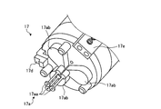
- 3A and 3B are schematic perspective views showing the configuration of the hand 17.
- 3B is an enlarged view of the tip of the hand 17 shown in FIG. 3A.
- the hand 17 attached to the first arm portion 11 includes a chuck portion 17a, a protruding portion 17b, and a gripper 17c.
- the chuck portion 17a includes three chuck claws 17aa.
- Each of the chuck claws 17aa has a base end portion supported by an individual rotating portion 17ab.
- the rotating portion 17ab is formed in a substantially teardrop shape, and is disposed so as to be rotatable around a rotation axis parallel to the extending direction of the hand 17.
- FIGS. 4A and 4B are schematic front views for explaining the chucking operation of the hand 17.
- 4A shows a state in which the chuck claw 17aa is closed
- FIG. 4B shows a state in which the chuck claw 17aa is opened.
- the state where the chuck claws 17aa are closed refers to a state where the chuck claws 17aa are gathered near the center of the tip of the hand 17.
- Such a state corresponds to a state in which the rotating unit 17ab is not driven.
- the chuck claw 17aa is opened when the rotating portion 17ab is driven to rotate around a rotation axis Ra parallel to the extending direction of the hand 17 so that the chuck claw 17aa is arced. It refers to a state where the hand 17 is opened outward while drawing a locus.
- FIG. 4B shows a state where the chuck claw 17aa is fully opened until it comes into contact with the protruding portion 17b.
- the opening and closing mechanism of the chuck claw 17aa using the rotating portion 17ab that rotates around the rotation axis Ra parallel to the extending direction of the hand 17, the size of the hand 17 is reduced, and the hand 17 is thin. The effect that it can be made can be obtained. Such a point is advantageous when the annular member is chucked from the inner peripheral side (described later).
- the rotating portion 17ab is formed in a substantially teardrop shape, and the rotating portion 17ab can be rotated without interfering with each other by being arranged so as to abut the tip of the thin body. Obtainable.
- the amount of opening and closing of the chuck claw 17aa is varied by controlling the amount of rotation of the rotating unit 17ab according to an operation instruction from the control device 20.
- the hand 17 can open the chuck claw 17aa from the center of the front end portion of the hand 17 to the outside, when the chuck object has a hollow shape such as an annular shape, The chuck can be chucked by pressing the chuck pawl 17aa to the circumferential side while opening it.
- the chuck object can be chucked by being sandwiched by the chuck claws 17aa from the outer peripheral side.
- the robot system 1 considering the advantages of the hand 17 that can chuck from both the inner and outer peripheral sides of the chuck target, it depends on the type of the chuck target, the processing mode, and the like.
- the chuck directions such as the inner peripheral side and the outer peripheral side are selected.
- the chuck method with the chuck direction as the outer peripheral side may be described as “outer peripheral chuck”, and the chuck method with the inner peripheral side as “inner peripheral chuck”.
- the hand 17 further includes a detent portion 17d and a sensor portion 17e.
- the anti-rotation portion 17d prevents the chuck object from rotating by being brought into contact with the end of the chuck object when the chuck claw 17aa “inner periphery chucks” the chuck object that is slippery on the inner periphery side. It is a member to prevent.
- the rotation preventing portion 17d is preferably formed of a rubber material or the like.
- the sensor unit 17e is a detection device configured using a color sensor or the like, and is used for identifying a chuck object chucked by the chuck claw 17aa.
- the protrusion 17b and the gripper 17c shown in FIG. 3A will be described in a series of operations of the robot 10 to be described later with reference to FIGS. 7A to 7H.
- FIG. 5 is a block diagram of the robot system 1 according to the embodiment.
- FIG. 5 only components necessary for the description of the robot system 1 are shown, and descriptions of general components are omitted.
- control device 20 In the description using FIG. 5, the internal configuration of the control device 20 will be mainly described, and the description of the various devices already shown in FIG. 1 may be simplified.
- the control device 20 includes a control unit 21 and a storage unit 22.
- the control unit 21 further includes a workpiece determination unit 21a, a chuck direction selection unit 21b, and an instruction unit 21c.
- the detection unit 5 shown outside the control device 20 is a block indicating the entire detection device such as the camera unit 100 (see FIG. 1) and the sensor unit 17e (see FIG. 3B).
- the control unit 21 performs overall control of the control device 20.
- the workpiece determination unit 21a receives detection information including the state of the workpiece W detected by the detection unit 5, and makes a status determination regarding the workpiece W based on the detection information.
- the situation determination regarding the workpiece W includes the identification determination of the workpiece W performed by matching the detection information and the workpiece identification information 22a.
- the workpiece identification information 22a is information relating to the identification of the workpiece W such as the shape and dimensions of the workpiece W, and is registered in the storage unit 22 in advance.
- work determination part 21a notifies the determination content with respect to the chuck
- the chuck direction selection unit 21b selects the chuck direction of the chuck claw 17aa based on the determination contents notified from the work determination unit 21a, the teaching information 22b, and the like.
- the chuck direction selection unit 21b notifies the instruction unit 21c of the selected chuck direction.
- the instruction unit 21c generates operation signals for operating various devices such as the robot 10, the hand 17 included in the robot 10, and the detection unit 5 based on the notified chuck direction and teaching information 22b, and outputs the operation signals to the various devices. .
- the teaching information 22b is information including teaching data for various devices of the robot system 1, and is registered in advance via an input device (not shown) (for example, a programming pendant).
- the teaching data includes a mode of machining operation performed on the workpiece W (specifically, information such as which member is assembled to the workpiece W in which order and how).
- the storage unit 22 is a storage device such as a hard disk drive or a nonvolatile memory, and stores work identification information 22a and teaching information 22b. Since the contents of the workpiece identification information 22a and the teaching information 22b have already been described, description thereof is omitted here.
- each component shown inside the control device 20 in FIG. 5 may not be arranged in the control device 20 alone.
- the throughput may be improved by storing any or all of the work identification information 22a and the teaching information 22b stored in the storage unit 22 in the internal memory of the robot 10.
- control device 20 has shown an example in which the situation determination regarding the workpiece W is performed based on the detection information from the detection unit 5, the workpiece identification information 22 a registered in advance, and the like. Necessary information may be sequentially acquired from a higher-level device connected to 20 to be able to communicate with each other.
- FIGS. 6A to 6D are schematic plan views of the workpiece W
- FIG. 6B is a schematic plan view of the first part p1
- FIG. 6C is a schematic plan view of the second part p2.
- FIG. 6D is a diagram showing an outline of the procedure for assembling the workpiece W.
- the workpiece W as a bracket is a member including an annular shape and has an inner peripheral portion Wi.
- the first part p1 which is a bearing, is an annular member, and has an inner peripheral part p1i and an outer peripheral part p1o.
- the second part p2 which is a retaining ring, is a substantially annular member, and has an inner peripheral part p2i and an outer peripheral part p2o.
- the first part p1 is attached to the inner peripheral portion Wi of the workpiece W (see the arrow 601 in the drawing).
- the second part p2 is attached to the upper part of the attached first part p1 (see arrow 602 in the figure).
- an adhesive agent is apply
- FIGS. 7A to 7H are explanatory views for explaining the procedure for assembling the workpiece W.
- FIG. 7A to 7H are explanatory views for explaining the procedure for assembling the workpiece W.
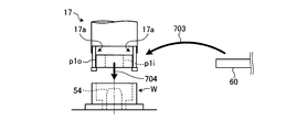
- the robot 10 takes out the workpiece W from the stocker 41 of the conveyance pallet 40 and conveys it while “inner circumferential chucking” the inner circumferential portion Wi by the chuck portion 17a of the hand 17 (in the drawing). Arrow 701). Then, the work W is placed on the work table 50 around the guiding jig 54 provided on the work table 50 (see arrow 702 in the figure).
- the guiding jig 54 is a jig for the purpose of guiding the first part p1.
- the robot 10 takes out the first part p1 from the first part supply unit 60 and conveys it while “peripheral chucking” the outer peripheral part p1o by the chuck part 17a of the hand 17 (FIG. 7B). Middle arrow 703).
- the “outer peripheral chuck” is performed here because it is necessary to guide the inner peripheral portion p1i of the first part p1 in contact with the peripheral portion of the guide jig 54.
- the robot 10 attaches the first part p1 to the inner peripheral portion Wi of the workpiece W while guiding the first part p1 with the guide jig 54 (see arrow 704 in the figure).
- the robot 10 places the jig J1 on the work W while the inner peripheral portion J1i is “inner peripheral chuck” by the chuck portion 17a of the hand 17 (arrow 705 in the drawing). reference).
- the inner peripheral portion J1i of the jig J1 is formed in a tapered shape that gradually decreases in diameter toward the lower side.
- the robot 10 takes out the second part p2 from the second part supply unit 70 and conveys it while “inner circumferential chucking” the inner circumferential part p2i by the chuck part 17a of the hand 17. (See arrow 706 in the figure).
- the “inner peripheral chuck” is performed in order to temporarily place the outer peripheral portion p2o (see FIG. 6C) of the second part p2 in contact with the inner peripheral portion J1i of the jig J1 (see FIG. 6). 7D arrow 707).
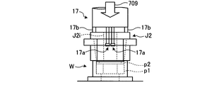
- the robot 10 moves the jig J2 to the second part p2 temporarily placed on the jig J1 while “inner circumferential chucking” the inner circumference J2i by the chuck portion 17a of the hand 17. Place (see arrow 708 in the figure).
- the robot 10 closes the chuck portion 17a of the hand 17 and stores it in the hollow portion inside the inner peripheral portion J2i of the jig J2, and moves the protruding portion 17b of the hand 17 to the jig J2. Touch to the end.
- the jig J2 is pressed from the direction indicated by the arrow 709 in the drawing, and the second part p2 is press-fitted into the upper part of the first part p1 attached to the workpiece W.
- the robot 10 conveys the workpiece W to the adhesive application unit 90 while being gripped by the gripper 17c of the hand 17, and the adhesive is applied to the attachment site of the first part p1 and the second part p2. Apply.
- the work W is transported to the imaging region of the camera unit 100, the application state of the adhesive is inspected by the imaging data, and then the work W is transported to the drying shelf 80 and stored (see arrow 710 in the figure).
- the gripper 17c is used in this procedure in order to reduce the risk of the chuck portion 17a being soiled by the adhesive.
- the robot 10 slides and pulls out the drying pallet 82 corresponding to each stage of the drying shelf 80 (see the arrow 712 in the figure) or stores it (see the arrow 711 in the figure). See). These operations can be performed when the robot 10 chucks the grip portion 81 attached to the drying pallet 82 with the chuck portion 17 a of the hand 17.
- the handle 81 in a shape in which a hole 81a is formed as shown in FIG. 7H.
- the hand 17 may be “inner chuck” with the chuck claw 17aa from the inside of the hole 81a (see three arrows in the figure).
- FIG. 8 is a schematic perspective view showing the slide operation of the transport pallet 40 by the robot 10. That is, as shown in FIG. 8, the robot 10 pulls the hand 17 by chucking the handle portion 42 (not shown) or the handle portion 43 (not shown) with the chuck claws 17aa and pulling the hand 17 up. The robot can be slid from the worker side area 32 to the robot side area 31 (see arrow 801 in the figure).
- the transport pallet 40 can be slid from the robot side area 31 to the worker side area 32 (see arrow 802 in the figure).
- the robot system 1 can cause the robot 10 to perform all the processes of processing the workpiece W from the loading of the workpiece W into and out of the cell 2 without exchanging the hand 17. That is, the workpiece W can be processed efficiently.
- FIG. 8 illustrates the case where the transport pallet 40 has a single-stage configuration
- a multi-stage configuration along the Z-axis direction may be used.
- a guide rail 33 that circulates in the workpiece supply unit 3 (see FIG. 1) over two stages is arranged and conveyed along the guide rail 33.
- the pallet 40 may be slid.
- the transport pallet 40 can be circulated in this way, the work W can be carried in and out without delay, and further efficiency can be achieved.
- the robot system includes a robot, a determination unit (work determination unit), a selection unit (chuck direction selection unit), and an instruction unit.
- the robot has a robot hand (hand) having three or more chuck claws.
- a determination part acquires the information regarding the member formed including the substantially cyclic
- the selection unit selects whether to hold the member from the inner peripheral side or the outer peripheral side with the chuck claws based on the determination result of the determination unit.
- the instruction unit conveys the member while holding the member with the chuck claw based on the selection result of the selection unit, and instructs the robot to assemble a predetermined workpiece using the member.
- the workpiece can be efficiently processed without enlarging the system.
- the case where there are three chuck claws has been described as an example.
- the number of chuck claws is not limited and may be at least three.
- the unit configured as a separate unit in the above-described embodiment may be configured as a single unit.
- the first part supply unit and the second part supply unit may be configured as one intermediate member supply unit.
- the single-arm robot is exemplified, but the present invention is not limited to this.
- a multi-arm robot having two or more arms may be used.
- a multi-axis robot having seven axes is exemplified, but the number of axes is not limited.
Abstract
Description
2 セル
3 ワーク供給部
5 検出部
10 ロボット
11 第1アーム部
12 第2アーム部
13 第3アーム部
14 第4アーム部
15 第5アーム部
16 基台部
17 ハンド
17a チャック部
17aa チャック爪
17ab 回転部
17b 突出部
17c グリッパ
17d 回り止め部
17e センサ部
20 制御装置
21 制御部
21a ワーク判定部
21b チャック方向選択部
21c 指示部
22 記憶部
22a ワーク識別情報
22b 教示情報
31 ロボット側エリア
32 作業者側エリア
33 ガイドレール
40 搬送パレット
41 ストッカ
42 把手部
43 把手部
50 作業台
51 第1作業台
52 第2作業台
53 治具収納部
54 誘い込み治具
60 第1パーツ供給ユニット
70 第2パーツ供給ユニット
80 乾燥棚
81 把手部
81a 穴部
82 乾燥パレット
90 接着剤塗布ユニット
100 カメラ部
J1 治具
J2 治具
W ワーク
p1 第1パーツ
p2 第2パーツ
Claims (5)
- 開閉する3個以上のチャック爪を具備したロボットハンドを有するロボットと、
略環状の形状を含んで形成された部材に関する情報を取得して該部材の状態を判定する判定部と、
前記判定部の判定結果に基づいて前記チャック爪で前記部材を内周側から保持するか又は外周側から保持するかを選択する選択部と、
前記選択部の選択結果に基づいて前記チャック爪で前記部材を保持しながら搬送するとともに、該部材を用いて所定の加工品を組み立てる動作を前記ロボットに対して指示する指示部と
を備えることを特徴とするロボットシステム。 - 前記ロボットハンドは、
前記チャック爪の基端部の近傍から該チャック爪の延伸方向と略平行に突き出して設けられた突出部を有しており、
前記指示部は、
前記部材を所定位置まで搬送した後、前記突出部を該部材の端部へ当接させて該部材を押圧する動作を前記ロボットに対して指示すること
を特徴とする請求項1に記載のロボットシステム。 - 前記ロボットハンドは、
前記チャック爪の基端部の近傍に設けられ、前記部材が前記チャック爪によって前記内周側から保持されている場合に、前記部材の端部へ当接されることによって前記部材の周方向まわりの回転を規制する回り止め部
をさらに備えることを特徴とする請求項1または2に記載のロボットシステム。 - 穴部が設けられた把手部を具備して棚状に形成され、組み立て後の前記加工品を一時的に収容する収容部
をさらに備え、
前記指示部は、
前記把手部における前記穴部の内側から前記チャック爪で保持しながら前記収容部をスライドさせて開閉する動作を前記ロボットに対して指示すること
を特徴とする請求項1、2または3に記載のロボットシステム。 - 前記把手部を具備して設けられ、組み立て前および組み立て後の前記加工品を収容する搬送パレット
をさらに備え、
前記指示部は、
前記把手部における前記穴部の内側から前記チャック爪で保持しながら前記搬送パレットをスライドさせて前記ロボットの作業スペースへ搬入出する動作を該ロボットに対して指示すること
を特徴とする請求項4に記載のロボットシステム。
Priority Applications (5)
| Application Number | Priority Date | Filing Date | Title |
|---|---|---|---|
| EP12874699.7A EP2839935A1 (en) | 2012-04-19 | 2012-04-19 | Robot system |
| JP2014511042A JPWO2013157119A1 (ja) | 2012-04-19 | 2012-04-19 | ロボットシステム |
| CN201280071832.1A CN104203504B (zh) | 2012-04-19 | 2012-04-19 | 机器人系统 |
| PCT/JP2012/060597 WO2013157119A1 (ja) | 2012-04-19 | 2012-04-19 | ロボットシステム |
| US14/505,499 US20150019003A1 (en) | 2012-04-19 | 2014-10-03 | Robot system |
Applications Claiming Priority (1)
| Application Number | Priority Date | Filing Date | Title |
|---|---|---|---|
| PCT/JP2012/060597 WO2013157119A1 (ja) | 2012-04-19 | 2012-04-19 | ロボットシステム |
Related Child Applications (1)
| Application Number | Title | Priority Date | Filing Date |
|---|---|---|---|
| US14/505,499 Continuation US20150019003A1 (en) | 2012-04-19 | 2014-10-03 | Robot system |
Publications (1)
| Publication Number | Publication Date |
|---|---|
| WO2013157119A1 true WO2013157119A1 (ja) | 2013-10-24 |
Family
ID=49383101
Family Applications (1)
| Application Number | Title | Priority Date | Filing Date |
|---|---|---|---|
| PCT/JP2012/060597 WO2013157119A1 (ja) | 2012-04-19 | 2012-04-19 | ロボットシステム |
Country Status (5)
| Country | Link |
|---|---|
| US (1) | US20150019003A1 (ja) |
| EP (1) | EP2839935A1 (ja) |
| JP (1) | JPWO2013157119A1 (ja) |
| CN (1) | CN104203504B (ja) |
| WO (1) | WO2013157119A1 (ja) |
Cited By (2)
| Publication number | Priority date | Publication date | Assignee | Title |
|---|---|---|---|---|
| US10588994B2 (en) * | 2015-05-11 | 2020-03-17 | Kabushiki Kaisha Yaskawa Denki | Life-science and/or medicinal chemistry automated manufacturing cell, life-science and/or medicinal chemistry automated manufacturing method, and automated manufacturing cell |
| US11633861B2 (en) * | 2019-03-01 | 2023-04-25 | Commscope Technologies Llc | Systems, methods and associated components for robotic manipulation of physical objects |
Families Citing this family (6)
| Publication number | Priority date | Publication date | Assignee | Title |
|---|---|---|---|---|
| EP3290168A4 (en) * | 2015-04-28 | 2018-12-12 | Seiko Epson Corporation | Robot system and robot |
| US10634625B2 (en) * | 2017-03-31 | 2020-04-28 | Sumitomo Chemical Company, Limited | Transfer system and transfer method |
| US20180281203A1 (en) * | 2017-03-31 | 2018-10-04 | Sumitomo Chemical Company, Limited | Robot arm and transfer system |
| JP2019063909A (ja) * | 2017-09-29 | 2019-04-25 | ファナック株式会社 | ロボット |
| JP7219148B2 (ja) * | 2018-04-25 | 2023-02-07 | 住友化学株式会社 | 検査システム及び検査システムの駆動方法 |
| CN113401853B (zh) * | 2021-06-23 | 2023-03-24 | 中国核动力研究设计院 | 一种用于干燥盐桶的开盖和封盖装置 |
Citations (17)
| Publication number | Priority date | Publication date | Assignee | Title |
|---|---|---|---|---|
| JPS5928487U (ja) * | 1982-08-12 | 1984-02-22 | 日本電産コパル株式会社 | ロボツトハンドの物品把持装置 |
| JPS5973286A (ja) * | 1982-10-16 | 1984-04-25 | 株式会社日平トヤマ | 搬送方法およびその装置 |
| JPS60161533U (ja) * | 1984-04-04 | 1985-10-26 | 日立精機株式会社 | フイ−ダの割出し装置 |
| JPS6133883A (ja) * | 1984-07-23 | 1986-02-17 | ユニメーション・インコーポレーテッド | ロボツトの把持装置 |
| JPS61169595U (ja) * | 1985-04-09 | 1986-10-21 | ||
| JPH0451327U (ja) * | 1990-09-03 | 1992-04-30 | ||
| JPH04133587U (ja) * | 1991-05-31 | 1992-12-11 | ぺんてる株式会社 | ユニバ−サル把持装置 |
| JP2002292589A (ja) * | 2001-03-30 | 2002-10-08 | Shindengen Electric Mfg Co Ltd | フランジ付き筒体のチャック装置 |
| JP2002331484A (ja) * | 2001-05-09 | 2002-11-19 | Honda Motor Co Ltd | 作業用ロボットの治工具交換方法及びその治工具ストッカ |
| JP2003062784A (ja) * | 2001-08-27 | 2003-03-05 | Shindengen Electric Mfg Co Ltd | フランジ付き筒体のチャック装置 |
| JP2003191193A (ja) * | 2001-12-21 | 2003-07-08 | Ricoh Co Ltd | スライド式チャック及びその把持方法、並びに記録媒体 |
| JP2003324909A (ja) | 2002-05-01 | 2003-11-14 | Fujitsu General Ltd | モータの組立装置 |
| JP2007223002A (ja) * | 2006-02-24 | 2007-09-06 | Honda Motor Co Ltd | 作業装置及びロボットによる作業方法 |
| JP2009291871A (ja) * | 2008-06-04 | 2009-12-17 | Mitsubishi Electric Corp | ロボット用把持ハンド |
| JP2011056627A (ja) * | 2009-09-10 | 2011-03-24 | Honda Motor Co Ltd | ハンドおよびマニプレータ装置 |
| JP2011156649A (ja) * | 2010-02-04 | 2011-08-18 | Yaskawa Electric Corp | グリッパ装置およびそのストローク量変更方法 |
| JP2012066321A (ja) * | 2010-09-22 | 2012-04-05 | Fuji Electric Co Ltd | ロボットシステムおよびロボット組立システム |
Family Cites Families (5)
| Publication number | Priority date | Publication date | Assignee | Title |
|---|---|---|---|---|
| JP4257570B2 (ja) * | 2002-07-17 | 2009-04-22 | 株式会社安川電機 | 搬送用ロボットのティーチング装置および搬送用ロボットのティーチング方法 |
| JP3876260B2 (ja) * | 2004-09-16 | 2007-01-31 | ファナック株式会社 | 物品供給装置 |
| JP4182074B2 (ja) * | 2005-03-03 | 2008-11-19 | ファナック株式会社 | ハンド及びハンドリングロボット |
| JP2008036716A (ja) * | 2006-08-01 | 2008-02-21 | Komatsu Machinery Corp | ワーク把持装置 |
| JP5229253B2 (ja) * | 2010-03-11 | 2013-07-03 | 株式会社安川電機 | ロボットシステム及びロボット装置並びにワーク取り出し方法 |
-
2012
- 2012-04-19 JP JP2014511042A patent/JPWO2013157119A1/ja active Pending
- 2012-04-19 WO PCT/JP2012/060597 patent/WO2013157119A1/ja active Application Filing
- 2012-04-19 EP EP12874699.7A patent/EP2839935A1/en not_active Withdrawn
- 2012-04-19 CN CN201280071832.1A patent/CN104203504B/zh not_active Expired - Fee Related
-
2014
- 2014-10-03 US US14/505,499 patent/US20150019003A1/en not_active Abandoned
Patent Citations (17)
| Publication number | Priority date | Publication date | Assignee | Title |
|---|---|---|---|---|
| JPS5928487U (ja) * | 1982-08-12 | 1984-02-22 | 日本電産コパル株式会社 | ロボツトハンドの物品把持装置 |
| JPS5973286A (ja) * | 1982-10-16 | 1984-04-25 | 株式会社日平トヤマ | 搬送方法およびその装置 |
| JPS60161533U (ja) * | 1984-04-04 | 1985-10-26 | 日立精機株式会社 | フイ−ダの割出し装置 |
| JPS6133883A (ja) * | 1984-07-23 | 1986-02-17 | ユニメーション・インコーポレーテッド | ロボツトの把持装置 |
| JPS61169595U (ja) * | 1985-04-09 | 1986-10-21 | ||
| JPH0451327U (ja) * | 1990-09-03 | 1992-04-30 | ||
| JPH04133587U (ja) * | 1991-05-31 | 1992-12-11 | ぺんてる株式会社 | ユニバ−サル把持装置 |
| JP2002292589A (ja) * | 2001-03-30 | 2002-10-08 | Shindengen Electric Mfg Co Ltd | フランジ付き筒体のチャック装置 |
| JP2002331484A (ja) * | 2001-05-09 | 2002-11-19 | Honda Motor Co Ltd | 作業用ロボットの治工具交換方法及びその治工具ストッカ |
| JP2003062784A (ja) * | 2001-08-27 | 2003-03-05 | Shindengen Electric Mfg Co Ltd | フランジ付き筒体のチャック装置 |
| JP2003191193A (ja) * | 2001-12-21 | 2003-07-08 | Ricoh Co Ltd | スライド式チャック及びその把持方法、並びに記録媒体 |
| JP2003324909A (ja) | 2002-05-01 | 2003-11-14 | Fujitsu General Ltd | モータの組立装置 |
| JP2007223002A (ja) * | 2006-02-24 | 2007-09-06 | Honda Motor Co Ltd | 作業装置及びロボットによる作業方法 |
| JP2009291871A (ja) * | 2008-06-04 | 2009-12-17 | Mitsubishi Electric Corp | ロボット用把持ハンド |
| JP2011056627A (ja) * | 2009-09-10 | 2011-03-24 | Honda Motor Co Ltd | ハンドおよびマニプレータ装置 |
| JP2011156649A (ja) * | 2010-02-04 | 2011-08-18 | Yaskawa Electric Corp | グリッパ装置およびそのストローク量変更方法 |
| JP2012066321A (ja) * | 2010-09-22 | 2012-04-05 | Fuji Electric Co Ltd | ロボットシステムおよびロボット組立システム |
Cited By (2)
| Publication number | Priority date | Publication date | Assignee | Title |
|---|---|---|---|---|
| US10588994B2 (en) * | 2015-05-11 | 2020-03-17 | Kabushiki Kaisha Yaskawa Denki | Life-science and/or medicinal chemistry automated manufacturing cell, life-science and/or medicinal chemistry automated manufacturing method, and automated manufacturing cell |
| US11633861B2 (en) * | 2019-03-01 | 2023-04-25 | Commscope Technologies Llc | Systems, methods and associated components for robotic manipulation of physical objects |
Also Published As
| Publication number | Publication date |
|---|---|
| CN104203504A (zh) | 2014-12-10 |
| JPWO2013157119A1 (ja) | 2015-12-21 |
| CN104203504B (zh) | 2016-03-09 |
| EP2839935A1 (en) | 2015-02-25 |
| US20150019003A1 (en) | 2015-01-15 |
Similar Documents
| Publication | Publication Date | Title |
|---|---|---|
| WO2013157119A1 (ja) | ロボットシステム | |
| TWI657903B (zh) | Manufacturing system, manufacturing system construction method, end effector, robot, and robot operation method | |
| JP6039187B2 (ja) | 組立装置、把持ハンドおよび物品の組立方法 | |
| EP2353796B1 (en) | Robot system and method of manufacturing a product | |
| US10589949B2 (en) | Robotic manipulation using reusable, independent tags | |
| JP6252597B2 (ja) | ロボットシステム | |
| US20150127160A1 (en) | Robot, robot system, and robot control apparatus | |
| JP6420533B2 (ja) | 作業装置 | |
| US20140364986A1 (en) | Robot system | |
| JP5479834B2 (ja) | ピッキング方法 | |
| JP5545322B2 (ja) | ロボットシステムおよび嵌合物の製造方法 | |
| JP6366665B2 (ja) | ロボット装置、組立装置、把持ハンド、および物品の製造方法 | |
| JP5999198B2 (ja) | ロボットシステム | |
| JP6314431B2 (ja) | ロボットシステム、制御装置、ロボット、及び駆動方法 | |
| WO2014132401A1 (ja) | ロボットシステム | |
| JP2015085480A (ja) | ロボット、制御装置、ロボットシステム、ロボット制御方法、及びプログラム | |
| WO2014132400A1 (ja) | ロボットシステム | |
| JP5365156B2 (ja) | ロボット装置 | |
| JP2014000645A (ja) | ロボットシステムおよび嵌合物の製造方法 | |
| JP2008307657A (ja) | ロボットハンド及びそれを備えたロボット |
Legal Events
| Date | Code | Title | Description |
|---|---|---|---|
| WWE | Wipo information: entry into national phase |
Ref document number: 201280071832.1 Country of ref document: CN |
|
| 121 | Ep: the epo has been informed by wipo that ep was designated in this application |
Ref document number: 12874699 Country of ref document: EP Kind code of ref document: A1 |
|
| ENP | Entry into the national phase |
Ref document number: 2014511042 Country of ref document: JP Kind code of ref document: A |
|
| WWE | Wipo information: entry into national phase |
Ref document number: 2012874699 Country of ref document: EP |
|
| NENP | Non-entry into the national phase |
Ref country code: DE |