WO2013146355A1 - Matériau de protection contre les rayons de chaleur et structure laminée - Google Patents
Matériau de protection contre les rayons de chaleur et structure laminée Download PDFInfo
- Publication number
- WO2013146355A1 WO2013146355A1 PCT/JP2013/057425 JP2013057425W WO2013146355A1 WO 2013146355 A1 WO2013146355 A1 WO 2013146355A1 JP 2013057425 W JP2013057425 W JP 2013057425W WO 2013146355 A1 WO2013146355 A1 WO 2013146355A1
- Authority
- WO
- WIPO (PCT)
- Prior art keywords
- heat ray
- shielding material
- ray shielding
- layer
- metal
- Prior art date
Links
Images


Classifications
-
- B—PERFORMING OPERATIONS; TRANSPORTING
- B32—LAYERED PRODUCTS
- B32B—LAYERED PRODUCTS, i.e. PRODUCTS BUILT-UP OF STRATA OF FLAT OR NON-FLAT, e.g. CELLULAR OR HONEYCOMB, FORM
- B32B5/00—Layered products characterised by the non- homogeneity or physical structure, i.e. comprising a fibrous, filamentary, particulate or foam layer; Layered products characterised by having a layer differing constitutionally or physically in different parts
- B32B5/16—Layered products characterised by the non- homogeneity or physical structure, i.e. comprising a fibrous, filamentary, particulate or foam layer; Layered products characterised by having a layer differing constitutionally or physically in different parts characterised by features of a layer formed of particles, e.g. chips, powder or granules
-
- G—PHYSICS
- G02—OPTICS
- G02B—OPTICAL ELEMENTS, SYSTEMS OR APPARATUS
- G02B5/00—Optical elements other than lenses
- G02B5/20—Filters
- G02B5/26—Reflecting filters
-
- B—PERFORMING OPERATIONS; TRANSPORTING
- B32—LAYERED PRODUCTS
- B32B—LAYERED PRODUCTS, i.e. PRODUCTS BUILT-UP OF STRATA OF FLAT OR NON-FLAT, e.g. CELLULAR OR HONEYCOMB, FORM
- B32B17/00—Layered products essentially comprising sheet glass, or glass, slag, or like fibres
- B32B17/06—Layered products essentially comprising sheet glass, or glass, slag, or like fibres comprising glass as the main or only constituent of a layer, next to another layer of a specific material
- B32B17/068—Layered products essentially comprising sheet glass, or glass, slag, or like fibres comprising glass as the main or only constituent of a layer, next to another layer of a specific material of particles
-
- B—PERFORMING OPERATIONS; TRANSPORTING
- B32—LAYERED PRODUCTS
- B32B—LAYERED PRODUCTS, i.e. PRODUCTS BUILT-UP OF STRATA OF FLAT OR NON-FLAT, e.g. CELLULAR OR HONEYCOMB, FORM
- B32B27/00—Layered products comprising a layer of synthetic resin
- B32B27/14—Layered products comprising a layer of synthetic resin next to a particulate layer
-
- B—PERFORMING OPERATIONS; TRANSPORTING
- B32—LAYERED PRODUCTS
- B32B—LAYERED PRODUCTS, i.e. PRODUCTS BUILT-UP OF STRATA OF FLAT OR NON-FLAT, e.g. CELLULAR OR HONEYCOMB, FORM
- B32B9/00—Layered products comprising a layer of a particular substance not covered by groups B32B11/00 - B32B29/00
- B32B9/04—Layered products comprising a layer of a particular substance not covered by groups B32B11/00 - B32B29/00 comprising such particular substance as the main or only constituent of a layer, which is next to another layer of the same or of a different material
- B32B9/041—Layered products comprising a layer of a particular substance not covered by groups B32B11/00 - B32B29/00 comprising such particular substance as the main or only constituent of a layer, which is next to another layer of the same or of a different material of metal
-
- B—PERFORMING OPERATIONS; TRANSPORTING
- B32—LAYERED PRODUCTS
- B32B—LAYERED PRODUCTS, i.e. PRODUCTS BUILT-UP OF STRATA OF FLAT OR NON-FLAT, e.g. CELLULAR OR HONEYCOMB, FORM
- B32B9/00—Layered products comprising a layer of a particular substance not covered by groups B32B11/00 - B32B29/00
- B32B9/04—Layered products comprising a layer of a particular substance not covered by groups B32B11/00 - B32B29/00 comprising such particular substance as the main or only constituent of a layer, which is next to another layer of the same or of a different material
- B32B9/048—Layered products comprising a layer of a particular substance not covered by groups B32B11/00 - B32B29/00 comprising such particular substance as the main or only constituent of a layer, which is next to another layer of the same or of a different material made of particles
-
- C—CHEMISTRY; METALLURGY
- C03—GLASS; MINERAL OR SLAG WOOL
- C03C—CHEMICAL COMPOSITION OF GLASSES, GLAZES OR VITREOUS ENAMELS; SURFACE TREATMENT OF GLASS; SURFACE TREATMENT OF FIBRES OR FILAMENTS MADE FROM GLASS, MINERALS OR SLAGS; JOINING GLASS TO GLASS OR OTHER MATERIALS
- C03C17/00—Surface treatment of glass, not in the form of fibres or filaments, by coating
- C03C17/006—Surface treatment of glass, not in the form of fibres or filaments, by coating with materials of composite character
- C03C17/007—Surface treatment of glass, not in the form of fibres or filaments, by coating with materials of composite character containing a dispersed phase, e.g. particles, fibres or flakes, in a continuous phase
-
- C—CHEMISTRY; METALLURGY
- C03—GLASS; MINERAL OR SLAG WOOL
- C03C—CHEMICAL COMPOSITION OF GLASSES, GLAZES OR VITREOUS ENAMELS; SURFACE TREATMENT OF GLASS; SURFACE TREATMENT OF FIBRES OR FILAMENTS MADE FROM GLASS, MINERALS OR SLAGS; JOINING GLASS TO GLASS OR OTHER MATERIALS
- C03C17/00—Surface treatment of glass, not in the form of fibres or filaments, by coating
- C03C17/006—Surface treatment of glass, not in the form of fibres or filaments, by coating with materials of composite character
- C03C17/008—Surface treatment of glass, not in the form of fibres or filaments, by coating with materials of composite character comprising a mixture of materials covered by two or more of the groups C03C17/02, C03C17/06, C03C17/22 and C03C17/28
-
- B—PERFORMING OPERATIONS; TRANSPORTING
- B32—LAYERED PRODUCTS
- B32B—LAYERED PRODUCTS, i.e. PRODUCTS BUILT-UP OF STRATA OF FLAT OR NON-FLAT, e.g. CELLULAR OR HONEYCOMB, FORM
- B32B2250/00—Layers arrangement
- B32B2250/02—2 layers
-
- B—PERFORMING OPERATIONS; TRANSPORTING
- B32—LAYERED PRODUCTS
- B32B—LAYERED PRODUCTS, i.e. PRODUCTS BUILT-UP OF STRATA OF FLAT OR NON-FLAT, e.g. CELLULAR OR HONEYCOMB, FORM
- B32B2255/00—Coating on the layer surface
- B32B2255/04—Coating on the layer surface on a particulate layer
-
- B—PERFORMING OPERATIONS; TRANSPORTING
- B32—LAYERED PRODUCTS
- B32B—LAYERED PRODUCTS, i.e. PRODUCTS BUILT-UP OF STRATA OF FLAT OR NON-FLAT, e.g. CELLULAR OR HONEYCOMB, FORM
- B32B2255/00—Coating on the layer surface
- B32B2255/20—Inorganic coating
-
- B—PERFORMING OPERATIONS; TRANSPORTING
- B32—LAYERED PRODUCTS
- B32B—LAYERED PRODUCTS, i.e. PRODUCTS BUILT-UP OF STRATA OF FLAT OR NON-FLAT, e.g. CELLULAR OR HONEYCOMB, FORM
- B32B2264/00—Composition or properties of particles which form a particulate layer or are present as additives
- B32B2264/10—Inorganic particles
- B32B2264/105—Metal
-
- B—PERFORMING OPERATIONS; TRANSPORTING
- B32—LAYERED PRODUCTS
- B32B—LAYERED PRODUCTS, i.e. PRODUCTS BUILT-UP OF STRATA OF FLAT OR NON-FLAT, e.g. CELLULAR OR HONEYCOMB, FORM
- B32B2264/00—Composition or properties of particles which form a particulate layer or are present as additives
- B32B2264/10—Inorganic particles
- B32B2264/107—Ceramic
-
- B—PERFORMING OPERATIONS; TRANSPORTING
- B32—LAYERED PRODUCTS
- B32B—LAYERED PRODUCTS, i.e. PRODUCTS BUILT-UP OF STRATA OF FLAT OR NON-FLAT, e.g. CELLULAR OR HONEYCOMB, FORM
- B32B2307/00—Properties of the layers or laminate
- B32B2307/30—Properties of the layers or laminate having particular thermal properties
- B32B2307/306—Resistant to heat
-
- B—PERFORMING OPERATIONS; TRANSPORTING
- B32—LAYERED PRODUCTS
- B32B—LAYERED PRODUCTS, i.e. PRODUCTS BUILT-UP OF STRATA OF FLAT OR NON-FLAT, e.g. CELLULAR OR HONEYCOMB, FORM
- B32B2307/00—Properties of the layers or laminate
- B32B2307/40—Properties of the layers or laminate having particular optical properties
- B32B2307/412—Transparent
-
- B—PERFORMING OPERATIONS; TRANSPORTING
- B32—LAYERED PRODUCTS
- B32B—LAYERED PRODUCTS, i.e. PRODUCTS BUILT-UP OF STRATA OF FLAT OR NON-FLAT, e.g. CELLULAR OR HONEYCOMB, FORM
- B32B2307/00—Properties of the layers or laminate
- B32B2307/50—Properties of the layers or laminate having particular mechanical properties
- B32B2307/584—Scratch resistance
-
- B—PERFORMING OPERATIONS; TRANSPORTING
- B32—LAYERED PRODUCTS
- B32B—LAYERED PRODUCTS, i.e. PRODUCTS BUILT-UP OF STRATA OF FLAT OR NON-FLAT, e.g. CELLULAR OR HONEYCOMB, FORM
- B32B2419/00—Buildings or parts thereof
-
- B—PERFORMING OPERATIONS; TRANSPORTING
- B32—LAYERED PRODUCTS
- B32B—LAYERED PRODUCTS, i.e. PRODUCTS BUILT-UP OF STRATA OF FLAT OR NON-FLAT, e.g. CELLULAR OR HONEYCOMB, FORM
- B32B2605/00—Vehicles
- B32B2605/006—Transparent parts other than made from inorganic glass, e.g. polycarbonate glazings
-
- Y—GENERAL TAGGING OF NEW TECHNOLOGICAL DEVELOPMENTS; GENERAL TAGGING OF CROSS-SECTIONAL TECHNOLOGIES SPANNING OVER SEVERAL SECTIONS OF THE IPC; TECHNICAL SUBJECTS COVERED BY FORMER USPC CROSS-REFERENCE ART COLLECTIONS [XRACs] AND DIGESTS
- Y10—TECHNICAL SUBJECTS COVERED BY FORMER USPC
- Y10T—TECHNICAL SUBJECTS COVERED BY FORMER US CLASSIFICATION
- Y10T428/00—Stock material or miscellaneous articles
- Y10T428/25—Web or sheet containing structurally defined element or component and including a second component containing structurally defined particles
Definitions
- the present invention relates to a heat ray shielding material and a laminated structure using the heat ray shielding material. Specifically, the present invention relates to a heat ray shielding material having good adhesion failure resistance and scratch resistance and low haze, and a bonded structure using the heat ray shielding material.
- heat ray shielding materials for automobiles and building windows have been developed as an energy-saving measure for reducing carbon dioxide. From the viewpoint of the heat ray shielding property (acquisition rate of solar heat), the heat ray reflection type without re-radiation is better than the heat ray absorption type with re-radiation of absorbed light into the room (about 1/3 of the absorbed solar energy).
- Various proposals have been made.
- a metal Ag thin film is generally used as a heat ray reflecting material because of its high reflectance, but it reflects not only visible light and heat rays but also radio waves, so that it has visible light permeability and radio wave permeability.
- Low-E glass for example, manufactured by Asahi Glass Co., Ltd.
- Ag and ZnO multilayer film is widely used in buildings in order to increase visible light transmittance, but Low-E glass is made of metal Ag on the glass surface. Since the thin film was formed, there existed a subject that radio wave permeability was low.
- Patent Document 1 includes a metal particle-containing layer containing at least one kind of metal particles, and the metal particles are hexagonal or circular plate-like metal particles.
- the example of Patent Document 1 discloses a heat ray shielding material in which a polyvinyl butyral solution is applied to the surface of an Ag hexagonal tabular grain fixed glass substrate and dried to provide a protective layer having a thickness of 1 ⁇ m.
- the present inventor examined the existence state of the flat metal particles in the metal particle-containing layer of the heat ray shielding material described in Patent Document 1, and found that if the plane orientation was too random, the heat ray shielding was inferior. Furthermore, when the inventor tried to paste the glass plate or the like as a heat ray shielding material, even when the plane orientation of the plate-like metal particles was uniform during film formation, it was flat when the glass plate was stuck to the window glass or the like as the heat ray shielding material. In some cases, the arrangement of the metal particles was not maintained, and in that case, the heat ray shielding function was inferior. Moreover, in the heat ray shielding material of the aspect described in patent document 1, it turned out that the problem of adhesion failure (blocking) arises.
- an object of the present invention is to provide a heat ray shielding material having good adhesion failure resistance and scratch resistance and low haze.
- the present inventor has at least one kind of metal particles, has 60% by number or more of hexagonal or circular plate metal particles, and the plate metal particles
- the overcoat layer is in close contact with at least one surface of the metal particle-containing layer in which the main plane is plane-oriented in an average range of 0 ° to ⁇ 30 ° with respect to one surface of the metal particle-containing layer
- the overcoat layer contains fine particles, it has been found that a heat ray shielding material having good adhesion failure resistance and scratch resistance and low haze can be obtained, and the present invention has been completed.
- a metal particle-containing layer containing at least one kind of metal particles, and an overcoat layer disposed in close contact with at least one surface of the metal particle-containing layer It has 60% by number or more of circular flat metal particles, and the main plane of the hexagonal or circular flat metal particles has an average of 0 ° to ⁇ 30 ° with respect to one surface of the metal particle-containing layer.
- the fine particles are preferably colloidal silica.
- the fine particles preferably have an average particle diameter of 5 to 1500 nm.
- the average particle diameter of the fine particles is preferably 5 to 300 nm.
- the heat ray shielding material according to any one of [1] to [4] preferably has a transmission haze of 3% or less.
- the overcoat layer further includes a binder, and the mass ratio of the fine particles to the binder in the overcoat layer is 0. It is preferably 0.02 to 0.4.
- the overcoat layer preferably has a thickness of 100 to 2000 nm.
- the overcoat layer when the thickness of the metal particle-containing layer is d, 80 pieces of the hexagonal or circular plate-like metal particles are provided. % Or more is preferably present in the range of d / 2 from the surface of the metal particle-containing layer.
- the heat ray shielding material according to [8] is in close contact with the surface of the metal particle-containing layer on which 80% by number or more of the hexagonal or circular tabular metal particles are unevenly distributed, It is preferable that an overcoat layer is disposed.
- the coefficient of variation in the particle size distribution of the hexagonal to circular plate-like metal particles is preferably 30% or less.
- the hexagonal to circular plate-like metal particles have an average particle diameter of 70 nm to 500 nm, and the hexagonal to circular shape.
- the aspect ratio (average particle diameter / average particle thickness) of the shaped tabular metal particles is preferably 8 to 40.
- the flat metal particles preferably include at least silver.
- the heat ray shielding material according to any one of [1] to [12] preferably has a visible light transmittance of 65% or more.
- the thickness of the base material is preferably 10 to 100 ⁇ m.
- the heat ray shielding material according to any one of [1] to [15] preferably further includes a metal oxide particle-containing layer containing at least one metal oxide particle.
- the metal oxide particles are preferably tin-doped indium oxide particles.
- the heat ray shielding material according to any one of [1] to [17] is preferably wound into a roll.
- the overcoat layer is preferably an adhesive layer.
- the above-mentioned problems can be solved, the object can be achieved, and a heat ray shielding material having good adhesion failure resistance and scratch resistance and low haze can be provided.
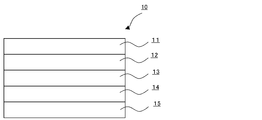
- FIG. 1 is a schematic view showing an example of the heat ray shielding material of the present invention.
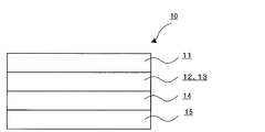
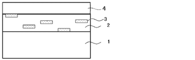
- FIG. 2 is a schematic view showing another example of the heat ray shielding material of the present invention.
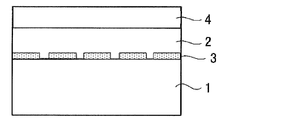
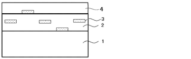
- FIG. 3 is a schematic view showing another example of the heat ray shielding material of the present invention.
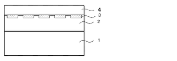
- FIG. 4 is a schematic view showing another example of the heat ray shielding material of the present invention.
- FIG. 5A is a schematic cross-sectional view showing an example of the existence state of a metal particle-containing layer containing hexagonal or circular plate-like metal particles in the heat ray shielding material of the present invention.
- FIG. 5A is a schematic cross-sectional view showing an example of the existence state of a metal particle-containing layer containing hexagonal or circular plate-like metal particles in the heat ray shielding material of the present invention.
- FIG. 5B is a schematic cross-sectional view showing the existence state of a metal particle-containing layer containing hexagonal or circular flat metal particles in the heat ray shielding material of the present invention, and is a hexagonal or circular flat metal.
- FIG. 5C is a schematic cross-sectional view showing the existence state of a metal particle-containing layer containing hexagonal or circular plate-like metal particles in the heat ray-shielding material of the present invention, and shows the heat ray-shielding material of the metal particle-containing layer. It is a figure which shows the presence area
- FIG. 5D is a schematic cross-sectional view showing another example of the existence state of the metal particle-containing layer containing hexagonal or circular plate-like metal particles in the heat ray shielding material of the present invention.
- FIG. 5E is a schematic cross-sectional view showing another example of the existence state of the metal particle-containing layer containing hexagonal or circular plate-like metal particles in the heat ray shielding material of the present invention.
- FIG. 5F is a schematic cross-sectional view showing another example of the existence state of the metal particle-containing layer containing hexagonal or circular plate-like metal particles in the heat ray shielding material of the present invention.
- FIG. 5G is a schematic cross-sectional view showing another example of the presence state of the metal particle-containing layer containing hexagonal or circular plate-like metal particles in the heat ray shielding material of the present invention.
- FIG. 6A is a schematic perspective view showing an example of the shape of a flat metal particle contained in the heat ray shielding material of the present invention, and shows a circular flat metal particle.
- FIG. 6B is a schematic perspective view showing an example of the shape of the flat metal particles contained in the heat ray shielding material of the present invention, and shows hexagonal flat metal particles.
- a numerical range represented by using “to” means a range including numerical values described before and after “to” as a lower limit value and an upper limit value.
- the heat ray shielding material of the present invention has a metal particle-containing layer containing at least one kind of metal particles, and an overcoat layer disposed in close contact with at least one surface of the metal particle-containing layer.
- it has 60% by number or more of hexagonal or circular flat metal particles, and the main plane of the hexagonal or circular flat metal particles has an average of 0 with respect to one surface of the metal particle-containing layer. It is characterized in that it is oriented in the range of ° to ⁇ 30 °, and the overcoat layer contains fine particles.
- the heat ray shielding material of the present invention has good adhesion failure resistance and scratch resistance and low haze.
- the haze of the heat ray shielding material of the present invention is preferably 3% or less from the viewpoint of improving appearance and visibility, more preferably 2.5% or less, and particularly preferably 2.2% or less. .
- the haze exceeds 20%, it may be unfavorable in terms of safety, for example, it may be difficult to see the outside when used as glass for automobiles or glass for buildings.
- the solar radiation reflectance of the heat ray shielding material of the present invention preferably has a maximum value in the range of 600 nm to 2,000 nm (preferably 800 nm to 1,800 nm) from the viewpoint that the efficiency of the heat ray reflectance can be increased. .
- the visible light transmittance of the heat ray shielding material of the present invention is preferably 60% or more, more preferably 65% or more, and particularly preferably 70% or more. When the visible light transmittance is less than 60%, for example, when used as automotive glass or building glass, the outside may be difficult to see.
- the ultraviolet ray transmittance of the heat ray shielding material of the present invention is preferably 5% or less, more preferably 2% or less. When the ultraviolet transmittance exceeds 5%, the color of the metal particle-containing layer may change due to ultraviolet rays of sunlight.
- the heat ray shielding material of the present invention preferably has an embodiment having other layers such as an adhesive layer, an ultraviolet absorption layer, a base material, and a metal oxide particle-containing layer as necessary.
- the heat ray shielding material 10 has a metal particle-containing layer 14 containing at least one metal particle, an overcoat layer 13, and the overcoat layer 13.
- fine-particles is mentioned.
- a base material 15 a metal particle-containing layer 14 on the base material, an overcoat layer 13 on the metal particle-containing layer, and an ultraviolet absorbing layer 12 on the overcoat layer,
- the aspect which has the adhesion layer 11 on this ultraviolet absorption layer is mentioned.
- FIG. 3 it has the overcoat layer 13 which functions also as the ultraviolet absorption layer 12 and the adhesion layer 11, the base material 15, the metal particle containing layer 14 on this base material, and this metal particle containing
- the overcoat layer 13 which functions also as the ultraviolet absorption layer 12 and the adhesion layer 11 on a layer is mentioned suitably.
- FIG. 4 it has an overcoat layer 13 that also functions as the ultraviolet absorption layer 12, a base material 15, a metal particle-containing layer 14 on the base material, and an ultraviolet ray on the metal particle-containing layer.
- an embodiment in which the overcoat layer 13 that also functions as the absorption layer 12 and the adhesive layer 11 on the overcoat layer 13 that also functions as the ultraviolet absorption layer 12 is preferably exemplified.
- the overcoat layer 13 containing fine particles as shown in FIGS. 1 to 4 hexagonal or circular plate-like metal particles contained in the metal particle-containing layer can be appropriately formed.
- scratch resistance can be imparted. This effect is particularly remarkable when the flat metal particles are segregated on the surface of the metal particle-containing layer on the overcoat layer side.
- the state wound up by roll shape may be sufficient. Since the heat ray shielding material of the present invention has good adhesion failure resistance, there are few failures when stacking the heat ray shielding materials of a plurality of the present invention in the case of a sheet, and it is wound up in a roll shape. Is less squeaky. In the case where the heat ray shielding material of the present invention is wound into a roll, it is preferably wound around a core having a diameter of 50 to 250 mm. The heat ray shielding material of the present invention preferably has good adhesion failure resistance in the range of 2 to 20 kg / cm 2 .
- Metal particle-containing layer is a layer containing at least one type of metal particles, and the metal particles have hexagonal or circular plate-like metal particles of 60% by number or more, and the hexagonal shape.
- the main plane of the flat metal particle having a circular shape is plane-oriented in an average range of 0 ° to ⁇ 30 ° with respect to one surface of the metal particle-containing layer.
- the flat metal particles can be segregated on one surface of the metal particle-containing layer.
- Metal particles have 60% by number or more of hexagonal or circular tabular metal particles, and the main plane of the hexagonal or circular tabular metal particles is on one surface of the metal particle-containing layer. On the other hand, there is no particular limitation as long as the plane orientation is in the range of 0 ° to ⁇ 30 ° on average, and it can be appropriately selected according to the purpose.
- the thickness of the metal particle-containing layer is d, it is preferable that 80% by number or more of the hexagonal or circular tabular metal particles exist in a range of d / 2 from the surface of the metal particle-containing layer. , D / 3 is more preferable.
- the metal particle-containing layer hexagonal to circular plate-like metal particles are present as one surface of the metal particle-containing layer (the surface of the substrate when the heat ray shielding material of the present invention has a substrate).
- the plane orientation is in the range of 0 ° to ⁇ 30 ° on the average.
- the hexagonal or circular plate-like metal particles have 80% by number or more of the hexagonal or circular plate-like metal particles of the metal particle-containing layer. It is preferable that it exists in the range of d / 2 from the surface, and it is more preferable that it exists in the range of d / 3.
- one surface of the said metal particle content layer is a flat plane.
- the metal particle-containing layer of the heat ray shielding material of the present invention has a base material as a temporary support, it is preferably substantially horizontal with the surface of the base material.
- the said heat ray shielding material may have the said temporary support body, and does not need to have it.
- size of the said metal particle According to the objective, it can select suitably, For example, you may have an average particle diameter of 500 nm or less.
- the material of the metal particles is not particularly limited and can be appropriately selected according to the purpose. From the viewpoint of high heat ray (near infrared) reflectance, silver, gold, aluminum, copper, rhodium, nickel, Platinum or the like is preferable.
- the flat metal particles are not particularly limited as long as they are particles composed of two main planes (see FIGS. 6A and 6B), and can be appropriately selected according to the purpose.
- hexagonal shape, circular shape examples include a triangle shape.
- a polygonal shape or a circular shape having a hexagonal shape or more is more preferable, and a hexagonal shape or a circular shape is particularly preferable.
- the circular shape means a shape in which the number of sides having a length of 50% or more of the average equivalent circle diameter of the flat metal particles described later is 0 per flat metal particle.
- the circular plate-like metal particles are not particularly limited as long as the plate-like metal particles have no corners and are round when viewed from above the main plane with a transmission electron microscope (TEM). It can be appropriately selected depending on the case.
- the hexagonal shape refers to a shape in which the number of sides having a length of 20% or more of the average equivalent circle diameter of the flat metal particles described later is 6 per flat metal particle. To tell. The same applies to other polygons.
- the hexagonal plate-like metal particles are not particularly limited as long as they are hexagonal when the plate-like metal particles are observed from above the main plane with a transmission electron microscope (TEM), and are appropriately selected according to the purpose.
- the hexagonal corner may be acute or dull, but the corner is preferably dull in that the absorption in the visible light region can be reduced.
- limiting in particular as a grade of the dullness of an angle According to the objective, it can select suitably.
- limiting in particular as a material of the said flat metal particle The same thing as the said metal particle can be suitably selected according to the objective.
- the flat metal particles preferably contain at least silver.
- hexagonal or circular plate-like metal particles are 60% by number or more, preferably 65% by number or more, and 70 by number with respect to the total number of metal particles. % Or more is more preferable. If the proportion of the flat metal particles is less than 60% by number, the visible light transmittance may be lowered.
- the hexagonal or circular plate-like metal particles have a main plane on one surface of the metal particle-containing layer (when the heat ray shielding material has a substrate, the surface of the substrate).
- it is plane-oriented in an average range of 0 ° to ⁇ 30 °, preferably plane-oriented in an average range of 0 ° to ⁇ 20 °, and plane-oriented in an average range of 0 ° to ⁇ 10 °. It is particularly preferable.
- the presence state of the flat metal particles is not particularly limited and may be appropriately selected depending on the purpose, but is preferably arranged as shown in FIGS. 5F and 5G described later.
- FIG. 5D to FIG. 5F, FIG. 5B and FIG. 5C are schematic cross-sectional views showing the existence state of the metal particle-containing layer containing flat metal particles in the heat ray shielding material of the present invention.
- FIGS. 5D to 5F show the state of the presence of the flat metal particles 3 in the metal particle-containing layer 2.
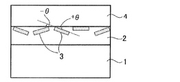
- FIG. 5B is a diagram for explaining an angle ( ⁇ ⁇ ) formed by the plane of the substrate 1 and the plane of the flat metal particles 3.
- FIG. 5C shows the existence region in the depth direction of the heat ray shielding material of the metal particle-containing layer 2.
- the angle ( ⁇ ⁇ ) formed by the surface of the substrate 1 and the main plane of the tabular metal particles 3 or an extension line of the main plane corresponds to a predetermined range in the plane orientation. That is, the plane orientation means a state where the inclination angle ( ⁇ ⁇ ) shown in FIG. 5B is small when the cross section of the heat ray shielding material is observed.
- FIG. 5F shows the surface of the substrate 1 and the flat metal particles 3. A state where the main plane is in contact, that is, a state where ⁇ is 0 ° is shown.
- a predetermined wavelength for example, from the visible light region long wavelength side
- the reflectance in the near infrared light region will be reduced.
- the main plane of the flat metal particles is plane-oriented with respect to one surface of the metal particle-containing layer (the surface of the substrate when the heat ray shielding material has a substrate)
- the surface of the substrate when the heat ray shielding material has a substrate there is no particular limitation.
- a suitable cross section is prepared, and a metal particle-containing layer (a base material when the heat ray shielding material has a base material) and flat metal particles in this section It may be a method of observing and evaluating.
- a microtome or a focused ion beam is used to prepare a cross-section sample or a cross-section sample of the heat ray shielding material, and this is used for various microscopes (for example, a field emission scanning electron microscope (FE-SEM) etc.), and a method of evaluating from an image obtained by observation.
- FE-SEM field emission scanning electron microscope
- the cross-section sample or the cross-section section is obtained by cutting a sample frozen in liquid nitrogen by a diamond cutter attached to a microtome. A sample may be made.
- covers a flat metal particle in a heat ray shielding material does not swell with water, you may produce the said cross-section sample or a cross-section piece sample.
- the surface of the metal particle-containing layer in the sample (the surface of the base material when the heat ray shielding material has a base material)
- the surface of the metal particle-containing layer in the sample there is no particular limitation as long as it can confirm whether or not the main plane is plane-oriented, and it can be appropriately selected according to the purpose.
- observation using an FE-SEM, TEM, optical microscope, etc. Can be mentioned.
- observation may be performed by FE-SEM
- observation may be performed by TEM.
- the average particle diameter (average equivalent circle diameter) of the flat metal particles is not particularly limited and may be appropriately selected depending on the intended purpose, but is preferably 70 nm to 500 nm, and more preferably 100 nm to 400 nm.
- the average particle diameter (average equivalent circle diameter) is less than 70 nm, the contribution of the absorption of the flat metal particles may be larger than the reflection, so that sufficient heat ray reflectivity may not be obtained.
- the haze (scattering) increases and the transparency of the substrate may be impaired.
- the average particle diameter means an average value of main plane diameters (maximum lengths) of 200 tabular grains arbitrarily selected from images obtained by observing grains with a TEM. To do. Two or more kinds of metal particles having different average particle diameters (average circle equivalent diameters) can be contained in the metal particle-containing layer. In this case, the peak of the average particle diameter (average circle equivalent diameter) of the metal particles is 2 It may have two or more, that is, two or more average particle diameters (average circle equivalent diameter).
- the coefficient of variation in the particle size distribution of the flat metal particles is preferably 30% or less, more preferably 20% or less. When the coefficient of variation exceeds 30%, the reflection wavelength region of the heat ray in the heat ray shielding material may become broad.
- the coefficient of variation in the particle size distribution of the flat metal particles is, for example, a plot of the particle diameter distribution range of the 200 flat metal particles used for calculating the average value obtained as described above, and a standard particle size distribution. The deviation is obtained, and is a value (%) divided by the average value (average particle diameter (average equivalent circle diameter)) of the main plane diameter (maximum length) obtained as described above.
- the aspect ratio of the flat metal particles is not particularly limited and may be appropriately selected depending on the intended purpose. However, since the reflectance in the infrared light region having a wavelength of 780 nm to 1,800 nm is increased, 8 ⁇ 40 are preferred, and 10 to 35 are more preferred. When the aspect ratio is less than 8, the reflection wavelength becomes smaller than 780 nm, and when it exceeds 40, the reflection wavelength becomes longer than 1,800 nm, and sufficient heat ray reflectivity may not be obtained.
- the aspect ratio means a value obtained by dividing the average particle diameter (average circle equivalent diameter) of the flat metal particles by the average particle thickness of the flat metal particles.
- the average grain thickness corresponds to the distance between the main planes of the flat metal particles, and is as shown in FIGS. 6A and 6B, for example, and can be measured by an atomic force microscope (AFM).
- the method for measuring the average particle thickness by the AFM is not particularly limited and can be appropriately selected according to the purpose. For example, a particle dispersion containing tabular metal particles is dropped onto a glass substrate and dried. And a method of measuring the thickness of one particle.
- the thickness of the flat metal particles is preferably 5 to 20 nm.
- the plasmon resonance wavelength ⁇ of the metal constituting the flat metal particle in the metal particle-containing layer is not particularly limited and can be appropriately selected according to the purpose. However, in terms of imparting heat ray reflection performance, 400 nm to 2 nm. , 500 nm is preferable, and from the viewpoint of imparting visible light transmittance, 700 nm to 2,500 nm is more preferable.
- the metal-containing layer preferably contains a polymer, and more preferably contains a transparent polymer.
- the polymer include polyvinyl acetal resin, polyvinyl alcohol resin, polyvinyl butyral resin, polyacrylate resin, polymethyl methacrylate resin, polycarbonate resin, polyvinyl chloride resin, (saturated) polyester resin, polyurethane resin, gelatin resin and cellulose. And polymers such as natural polymers.
- the main polymer of the polymer is preferably a polyvinyl alcohol resin, a polyvinyl butyral resin, a polyvinyl chloride resin, a (saturated) polyester resin, a polyurethane resin, and preferably the polyester resin and the polyurethane resin. More preferably, 80% by number or more of hexagonal or circular plate-like metal particles are present in the range of d / 2 from the surface of the metal particle-containing layer, and the heat ray shielding material of the present invention is a polyester resin. It is particularly preferable from the viewpoint of further improving the resistance to rubbing.
- the main polymer of the polymer contained in the metal-containing layer refers to a polymer component occupying 50% by mass or more of the polymer contained in the metal-containing layer.
- the refractive index n of the medium is preferably 1.4 to 1.7.
- n of the medium is preferably 1.4 to 1.7.
- the thickness of the hexagonal or circular plate-like metal particles is a
- 80% or more of the hexagonal or circular plate-like metal particles are a / in the thickness direction. It is preferable that 10 or more is covered with the polymer, a / 10 to 10a in the thickness direction is more preferably covered with the polymer, and a / 8 to 4a is covered with the polymer. Particularly preferred.
- the hexagonal or circular plate-like metal particles are buried in the metal particle-containing layer at a certain ratio or more, whereby the rubbing resistance can be further increased. That is, the heat ray shielding material of the present invention is preferably in the mode of FIG. 5F rather than the mode of FIG. 5G.
- the area ratio of flat metal particles The area of the flat metal particles with respect to the area A of the base material when the heat ray shielding material is viewed from above (the total projected area A of the metal particle-containing layer when viewed from the direction perpendicular to the metal particle-containing layer)
- the area ratio [(B / A) ⁇ 100] which is the ratio of the total value B, is preferably 15% or more, and more preferably 20% or more.
- the area ratio can be measured, for example, by performing image processing on an image obtained by SEM observation of the heat ray shielding base material from above or an image obtained by AFM (atomic force microscope) observation. .
- the average inter-particle distance between the tabular metal particles adjacent in the horizontal direction in the metal particle-containing layer is 1/10 or more of the average particle diameter of the tabular metal particles from the viewpoint of visible light transmittance and maximum heat ray reflectance. Is preferred.
- the average inter-particle distance in the horizontal direction of the flat metal particles is less than 1/10 of the average particle diameter of the flat metal particles, the visible light transmittance is lowered. On the other hand, if it is 10 or more, the heat ray reflectance is lowered.
- the average interparticle distance in the horizontal direction is preferably non-uniform (random) in terms of visible light transmittance. If it is not random, that is, if it is uniform, moire fringes may be seen due to diffraction scattering.
- the average inter-particle distance in the horizontal direction of the flat metal particles means an average value of inter-particle distances between two adjacent particles.
- the average inter-particle distance is random as follows: “When the two-dimensional autocorrelation of the luminance value when binarizing an SEM image including 100 or more tabular metal particles is taken, Does not have a significant local maximum. "
- the flat metal particles are arranged in the form of a metal particle-containing layer containing flat metal particles, as shown in FIGS. 5B, 5C, and 5D to 5F.
- the metal particle-containing layer may be composed of a single layer as shown in FIGS. 5B, 5C, and 5D to 5F, or may be composed of a plurality of metal particle-containing layers. When comprised with a several metal particle content layer, it becomes possible to provide the shielding performance according to the wavelength range
- Thickness of metal particle containing layer The thickness d of the metal particle-containing layer preferably satisfies a / 2 ⁇ d ⁇ 2b, where a is the thickness of the metal particles and b is the average particle diameter (average equivalent circle diameter). It is more preferable to satisfy d ⁇ b. If d is too thin, the metal particle-containing layer will be difficult to hold the metal particles, and the metal particles will be easily peeled off during stacking and transporting. Conversely, if d is too thick, the metal particles will contain metal particles. It becomes difficult to be unevenly distributed on the surface of the layer.
- the thickness of each layer of the metal particle-containing layer can be measured, for example, from an image obtained by SEM observation of a cross-sectional sample of the heat ray shielding material.
- the boundary between the other layer and the metal particle-containing layer is determined by the same method.
- the thickness d of the metal particle-containing layer can be determined.
- it is difficult to determine the boundary with the metal particle-containing layer. By coating the overcoat layer after carbon deposition on the containing layer and observing the cross section with an SEM, the interface between the two layers can be recognized, and the thickness d of the metal particle containing layer can be determined. it can.
- the method for synthesizing the flat metal particles is not particularly limited as long as it can synthesize hexagonal to circular flat metal particles, and can be appropriately selected according to the purpose.
- a chemical reduction method And liquid phase methods such as a photochemical reduction method and an electrochemical reduction method.
- a liquid phase method such as a chemical reduction method or a photochemical reduction method is particularly preferable in terms of shape and size controllability.
- the metal particles for example, Ag
- the metal particles may be crystal-grown in a flat shape.
- the flat metal particles may be subjected to further treatment in order to impart desired characteristics.
- the further treatment is not particularly limited and may be appropriately selected depending on the purpose.
- the formation of a high refractive index shell layer the addition of various additives such as a dispersant and an antioxidant may be included. Can be mentioned.
- the flat metal particles may be coated with a high refractive index material having high visible light region transparency in order to further enhance visible light region transparency.
- a high refractive index material is not particularly limited and may be appropriately selected depending on the purpose, for example, TiO x, BaTiO 3, ZnO, etc. SnO 2, ZrO 2, NbO x and the like.
- an SiO 2 or polymer shell layer is appropriately formed. Further, the metal oxide layer may be formed on the shell layer.
- TiO x is used as a material for the high refractive index metal oxide layer, since TiO x has photocatalytic activity, there is a concern that the matrix in which the plate-like metal particles are dispersed may be deteriorated. After the TiO x layer is formed on the flat metal particles, an SiO 2 layer may be appropriately formed.
- the flat metal particles may adsorb an antioxidant such as mercaptotetrazole or ascorbic acid in order to prevent oxidation of metals such as silver constituting the flat metal particles.
- an oxidation sacrificial layer such as Ni may be formed on the surface of the flat metal particles. Further, it may be covered with a metal oxide film such as SiO 2 for the purpose of blocking oxygen.
- the flat metal particles are, for example, a low molecular weight dispersant, a high molecular weight dispersant or the like containing at least one of an N element such as a quaternary ammonium salt and amines, an S element, and a P element.
- a dispersant may be added.
- the heat ray shielding material of the present invention has an overcoat layer disposed in close contact with the surface of the metal particle-containing layer, and the overcoat layer contains fine particles.
- the heat ray shielding material of the present invention has an overcoat layer, particularly when tabular metal particles are unevenly distributed on the surface of the metal particle-containing layer, preventing contamination of the manufacturing process due to stripping of the tabular metal particles, when applying another layer It is possible to prevent the disorder of the arrangement of the flat metal particles.
- the fine particles may be inorganic fine particles or organic fine particles, but are preferably inorganic fine particles.
- the inorganic fine particles include oxides (for example, colloidal silica, titanium oxide, magnesium oxide, aluminum oxide), alkaline earth metal salts (for example, sulfates and carbonates, specifically, barium sulfate, carbonates). Calcium, magnesium sulfate, strontium sulfate, calcium carbonate, etc.), silver halide grains and glass that do not form an image.
- Inorganic particles described in US Pat. Nos. 4,021,245 and 4,029,504 can also be used.
- colloidal silica, titanium oxide, barium sulfate, silver halide and the like are preferable, and colloidal silica is particularly preferable.
- colloidal silica include E.I. I. du ponte de Nemours & Co.
- Ludox AM Ludox AM
- Ludox AS Ludox AS
- Ludox LS Ludox HS
- Nissan Chemical Co., Ltd. Tokyo, Japan
- Snowtex 20 Snowtex C
- Snowtex N Snowtex N
- Snowtex O etc.
- Monsanto Co. USA
- Syton C-30 Syton-200
- Nalco Chem. Co. USA
- a tin dioxide-antimony composite acicular metal oxide aqueous dispersion commercially available from Ishihara Sangyo under the product name FS-10D can also be used.
- a water-dispersed polymer (latex) is preferably used.
- an ester of acrylic acid or methacrylic acid particularly methyl, ethyl, n-propyl, isopropyl, n-butyl, isobutyl, t-butyl, hexyl
- Polymers containing an alkyl group having 1 to 10 carbon atoms such as 2-ethylhexyl, heptyl, n-octyl or the like and unsaturated carboxylic acid components such as acrylic acid, methacrylic acid, fumaric acid, itaconic acid, maleic acid And acrylonitrile, methacrylonitrile, halogen-substituted acrylonitrile, halogen-substituted methacrylonitrile, acrylamide, methacrylamide, N-methylol acrylonitrile, N-ethanol acrylamide, N-methyl acrylamide, N-propanol acryl Mido, N-methylolmethacrylamide, Nt-butylacrylamide,
- vinyl esters such as vinyl acetate, vinyl chloroacetate, and vinyl benzoate, vinyl pyridine, vinyl chloride, and butadiene.
- These water-dispersed polymers can be obtained by dispersing a mixture of these monomers in water using a surfactant and then polymerizing with a normal radical initiator.
- the average particle diameter of the fine particles is preferably 5 to 1500 nm, more preferably 5 to 900 nm, and particularly preferably 5 to 300 nm.
- the average particle diameter of the fine particles is preferably 5 to 1500 nm, more preferably 5 to 900 nm, and particularly preferably 5 to 300 nm.
- the mass ratio of the fine particles to the binder in the overcoat layer is preferably 0.02 to 0.4, more preferably 0.02 to 0.3, and 0.02 to 0.2. It is particularly preferred that
- the overcoat layer is not particularly limited except that it contains fine particles, and can be appropriately selected according to the purpose.
- Examples of the overcoat layer include binders, matting agents, cross-linking agents, slip agents, and surface antifouling agents. Further, it contains a refractive index adjusting agent and a surfactant, and may further contain other components as necessary.
- the binder is not particularly limited and may be appropriately selected depending on the purpose. For example, thermosetting of acrylic resin, silicone resin, melamine resin, urethane resin, alkyd resin, fluorine resin, etc. Mold or photo-curable resin. Moreover, the binder illustrated in the said ultraviolet absorption layer can be used. Moreover, you may further provide the function as an overcoat layer to functional layers, such as the below-mentioned ultraviolet absorption layer, an adhesion layer, and a hard-coat layer.
- the thickness of the overcoat layer is preferably 100 to 2000 nm, more preferably 100 to 2000 nm, and particularly preferably 150 to 2000 nm.
- a thin film of about 100 nm is usually preferred in consideration of the amount of material used and the surface roughness.
- the thickness is preferably 150 nm or more. However, this is not the case when the refractive indexes of the adhesive layer and the overcoat layer are matched.
- bar coating is advantageous to reduce the manufacturing cost, it is preferable to set the dry thickness of the overcoat layer to 2000 nm or less in consideration of the general viscosity and wet coating amount.
- the heat ray shielding material of the present invention preferably further has a base material on the surface of the metal particle-containing layer opposite to the surface on which the overcoat layer is disposed.
- the substrate is not particularly limited as long as it is an optically transparent substrate, and can be appropriately selected according to the purpose.
- the substrate has a visible light transmittance of 70% or more, preferably 80% or more. And those with high transmittance in the near infrared region.
- the shape examples include a flat plate shape, and the structure may be a single layer structure or a laminated structure, and the size may be the size of the heat ray shielding material. It can be appropriately selected according to the above.
- the material for the substrate is not particularly limited and may be appropriately selected depending on the intended purpose.
- polyolefin resins such as polyethylene, polypropylene, poly-4-methylpentene-1, polybutene-1, polyethylene terephthalate
- Polyester resins such as polyethylene naphthalate
- polycarbonate resins polyvinyl chloride resins
- polyphenylene sulfide resins polyether sulfone resins
- polyethylene sulfide resins polyphenylene ether resins
- styrene resins acrylic resins
- polyamides examples thereof include a film made of a cellulose resin such as a cellulose resin, a polyimide resin, and cellulose acetate, or a laminated film thereof.
- a polyethylene terephthalate film is particularly preferable.
- the thickness of the base material is not particularly limited and can be appropriately selected according to the purpose of use of the solar shading film. Usually, the thickness is about 10 ⁇ m to 500 ⁇ m, but the thinner one is preferable from the viewpoint of thinning. preferable.
- the thickness of the substrate is preferably 10 ⁇ m to 100 ⁇ m, more preferably 20 to 75 ⁇ m, and particularly preferably 35 to 75 ⁇ m.
- the thickness of the base material is reduced, the strength as a heat ray shielding material is insufficient, or adhesion failure tends to occur.
- fine particles having a preferred particle size defined in the present invention for the overcoat layer adhesion failure can be reduced even when a thin substrate is used.
- the said base material becomes thick, when it bonds together to a building material and a motor vehicle as a heat ray shielding material, there exists a tendency for the waist as a material to be strong and to become difficult to construct. Furthermore, since the base material is thick, the visible light transmittance tends to decrease and the raw material cost tends to increase.
- the heat ray shielding material of the present invention may further include a metal oxide particle-containing layer containing at least one metal oxide particle as a layer that absorbs long-wave infrared rays. From the viewpoint of balance, it is preferable.
- the metal oxide particle-containing layer is a surface of the metal particle-containing layer on which the hexagonal or circular plate-like metal particles of the metal particle-containing layer are exposed. It is preferable to have on the opposite surface side. In this case, for example, the metal oxide particle-containing layer may be laminated with the metal particle-containing layer via a base material.
- the heat ray shielding material of the present invention when the heat ray shielding material of the present invention is disposed so that the metal particle-containing layer 2 is on the incident direction side of heat rays such as sunlight, a part of the heat rays (or the metal particle-containing layer (or After reflection, all of the heat rays are absorbed by the metal oxide-containing layer, and the inside of the heat-ray shielding material is caused by the heat rays that are not absorbed by the metal particle-containing layer and pass through the heat ray shielding material. It is possible to reduce the amount of heat received directly at the heat amount and the total amount of heat absorbed by the metal oxide-containing layer of the heat ray shielding material and indirectly transmitted to the inside of the heat ray shielding material.
- the said metal oxide particle content layer is a layer containing at least 1 sort (s) of metal oxide particle, there will be no restriction
- limiting in particular as a material of the said metal oxide particle According to the objective, it can select suitably, For example, a tin dope indium oxide (henceforth "ITO”), a tin dope antimony oxide (henceforth). , Abbreviated as “ATO”), zinc oxide, titanium oxide, indium oxide, tin oxide, antimony oxide, glass ceramics, and the like.
- ITO, ATO, and zinc oxide are more preferable, and infrared rays having a wavelength of 1,200 nm or more are 90% in that they have excellent heat ray absorption ability and can produce heat ray shielding materials having a wide range of heat ray absorption ability when combined with silver tabular grains.
- ITO is preferable in that it has a visible light transmittance of 90% or more.
- the volume average particle size of the primary particles of the metal oxide particles is preferably 0.1 ⁇ m or less in order not to reduce the visible light transmittance.
- limiting in particular as a shape of the said metal oxide particle According to the objective, it can select suitably, For example, spherical shape, needle shape, plate shape, etc. are mentioned.
- the content of the metal oxide particles in the metal oxide particle-containing layer is not particularly limited and may be appropriately selected depending on the purpose, but is preferably 0.1 g / m 2 to 20 g / m 2 , 0.5 g / m 2 to 10 g / m 2 is more preferable, and 1.0 g / m 2 to 4.0 g / m 2 is more preferable. If the content is less than 0.1 g / m 2 , the amount of solar radiation felt on the skin may increase, and if it exceeds 20 g / m 2 , the visible light transmittance may deteriorate.
- the content of the metal oxide particles in the metal oxide particle-containing layer is, for example, from the observation of the super foil section TEM image and surface SEM image of the heat ray shielding layer, and the number of metal oxide particles in a certain area and It can be calculated by measuring the average particle diameter and dividing the mass (g) calculated based on the number and average particle diameter and the specific gravity of the metal oxide particles by the constant area (m 2 ). .
- metal oxide fine particles in a certain area of the metal oxide particle-containing layer are eluted in methanol, and the mass (g) of the metal oxide fine particles measured by fluorescent X-ray measurement is divided by the constant area (m 2 ). This can also be calculated.
- the ultraviolet absorbing layer is not particularly limited as long as it is a layer containing at least one ultraviolet absorber, and can be appropriately selected according to the purpose, and may be an adhesive layer. It may be a layer (for example, an overcoat layer, a base material, an intermediate layer other than these) between the adhesive layer and the metal particle-containing layer. In any case, it is preferable that the ultraviolet absorbing layer is disposed on the side irradiated with sunlight with respect to the metal particle-containing layer. In the case where the ultraviolet absorbing layer forms an intermediate layer that is neither an adhesive layer nor a substrate, the ultraviolet absorbing layer contains at least one ultraviolet absorber, and, if necessary, a binder or the like Of other ingredients.
- the heat ray shielding material of the present invention preferably has an ultraviolet absorbing layer on the surface side of the metal particle-containing layer where the hexagonal or circular flat metal particles are exposed.
- the overcoat layer and the ultraviolet absorbing layer described later may be the same or different.
- the overcoat layer is a layer between the ultraviolet absorption layer and the metal particle-containing layer, and the overcoat layer is the ultraviolet absorption layer. It is also preferable.
- UV absorbers The ultraviolet absorber is not particularly limited and may be appropriately selected depending on the purpose. For example, a benzophenone ultraviolet absorber, a benzotriazole ultraviolet absorber, a triazine ultraviolet absorber, a salicylate ultraviolet absorber, Examples include cyanoacrylate ultraviolet absorbers. These may be used individually by 1 type and may use 2 or more types together.
- the benzophenone-based ultraviolet absorber is not particularly limited and may be appropriately selected depending on the intended purpose. Examples thereof include 2,4droxy-4-methoxy-5-sulfobenzophenone.
- the benzotriazole ultraviolet absorber is not particularly limited and may be appropriately selected depending on the intended purpose.
- the triazine ultraviolet absorber is not particularly limited and may be appropriately selected depending on the intended purpose. Examples thereof include mono (hydroxyphenyl) triazine compounds, bis (hydroxyphenyl) triazine compounds, and tris (hydroxyphenyl) triazine compounds. Etc. Examples of the mono (hydroxyphenyl) triazine compound include 2- [4-[(2-hydroxy-3-dodecyloxypropyl) oxy] -2-hydroxyphenyl] -4,6-bis (2,4-dimethyl).
- Phenyl) -1,3,5-triazine 2- [4-[(2-hydroxy-3-tridecyloxypropyl) oxy] -2-hydroxyphenyl] -4,6-bis (2,4-dimethylphenyl) ) -1,3,5-triazine, 2- (2,4-dihydroxyphenyl) -4,6-bis (2,4-dimethylphenyl) -1,3,5-triazine, 2- (2-hydroxy- 4-isooctyloxyphenyl) -4,6-bis (2,4-dimethylphenyl) -1,3,5-triazine, 2- (2-hydroxy-4-dodecyloxyphenyl) -4,6-bis ( 2,4-dimethylphenyl) -1,3,5-triazine, etc.
- Examples of the bis (hydroxyphenyl) triazine compound include 2,4-bis (2-hydroxy-4-propyloxyphenyl) -6- (2,4-dimethylphenyl) -1,3,5-triazine, 2 , 4-Bis (2-hydroxy-3-methyl-4-propyloxyphenyl) -6- (4-methylphenyl) -1,3,5-triazine, 2,4-bis (2-hydroxy-3-methyl) -4-hexyloxyphenyl) -6- (2,4-dimethylphenyl) -1,3,5-triazine, 2-phenyl-4,6-bis [2-hydroxy-4- [3- (methoxyheptaethoxy ) -2-hydroxypropyloxy] phenyl] -1,3,5-triazine and the like.
- tris (hydroxyphenyl) triazine compound examples include 2,4-bis (2-hydroxy-4-butoxyphenyl) -6- (2,4-dibutoxyphenyl) -1,3,5-triazine, 2 , 4,6-Tris (2-hydroxy-4-octyloxyphenyl) -1,3,5-triazine, 2,4,6-tris [2-hydroxy-4- (3-butoxy-2-hydroxypropyloxy) ) Phenyl] -1,3,5-triazine, 2,4-bis [2-hydroxy-4- [1- (isooctyloxycarbonyl) ethoxy] phenyl] -6- (2,4-dihydroxyphenyl) -1 , 3,5-triazine, 2,4,6-tris [2-hydroxy-4- [1- (isooctyloxycarbonyl) ethoxy] phenyl] -1,3,5-triazine, 2,4-bis [2 -Hydroxy-4
- the salicylate-based ultraviolet absorber is not particularly limited and may be appropriately selected depending on the intended purpose. Examples thereof include phenyl salicylate, p-tert-butylphenyl salicylate, p-octylphenyl salicylate, Examples include 2-ethylhexyl salicylate.
- the cyanoacrylate-based ultraviolet absorber is not particularly limited and may be appropriately selected depending on the intended purpose.
- binder- The binder used in the ultraviolet absorbing layer is not particularly limited and may be appropriately selected depending on the purpose, but preferably has higher visible light transparency and higher solar transparency, such as acrylic resin, polyvinyl butyral, Examples include polyvinyl alcohol.
- the ultraviolet absorbing layer formed between the heat ray source and the flat metal particles has a wavelength range of 450 nm to 1,500 nm. It is preferable to select a material that does not absorb light or to reduce the thickness of the ultraviolet absorbing layer.
- the thickness of the ultraviolet absorbing layer is preferably 0.01 ⁇ m to 1,000 ⁇ m, more preferably 0.02 ⁇ m to 500 ⁇ m.
- the absorption of ultraviolet rays may be insufficient, and when it exceeds 1,000 ⁇ m, the visible light transmittance may decrease.
- the content of the ultraviolet absorbing layer varies depending on the ultraviolet absorbing layer to be used and cannot be generally defined, but it is preferable to appropriately select a content that gives a desired ultraviolet transmittance in the heat ray shielding material of the present invention.
- the ultraviolet transmittance is preferably 5% or less, and more preferably 2% or less. When the ultraviolet transmittance exceeds 5%, the color of the metal particle-containing layer may change due to ultraviolet rays of sunlight.
- the heat ray shielding material of the present invention preferably has an adhesive layer.
- the adhesive layer may be the overcoat layer, an adhesive layer having the function of the ultraviolet absorbing layer, or an adhesive layer not containing the ultraviolet absorber.
- the material that can be used for forming the adhesive layer is not particularly limited and may be appropriately selected depending on the intended purpose.
- An adhesive layer made of these materials can be formed by coating.
- an antistatic agent, a lubricant, an antiblocking agent and the like may be added to the adhesive layer.
- the thickness of the adhesive layer is preferably 0.1 ⁇ m to 10 ⁇ m.
- the heat ray shielding material includes a hard coat layer having hard coat properties.
- a hard coat layer having hard coat properties.
- the kind and formation method can be selected suitably according to the objective, for example, acrylic resin, silicone resin, melamine resin, urethane resin, alkyd resin And thermosetting or photocurable resins such as fluorine-based resins.
- the thickness of the hard coat layer is not particularly limited and may be appropriately selected depending on the intended purpose, but is preferably 1 ⁇ m to 50 ⁇ m.
- the hard coat layer may contain the metal oxide particles.
- a protective layer other than the overcoat layer may be provided in order to improve the adhesion to the base material or to protect it from mechanical strength.
- a protective layer there is no restriction
- limiting in particular as said binder According to the objective, it can select suitably, The binder illustrated in the said ultraviolet absorption layer can be used.
- the method for forming the metal particle-containing layer of the present invention is not particularly limited and may be appropriately selected depending on the purpose.
- the dispersion having the flat metal particles on the surface of the lower layer such as the substrate examples include a method in which the liquid is applied by a dip coater, a die coater, a slit coater, a bar coater, a gravure coater, or the like, and a method in which the liquid is aligned by a method such as an LB film method, a self-assembly method, or a spray coating.
- the method of applying with a bar coater is preferable.
- the composition of the metal particle-containing layer used in the examples described later, the latex is added and 80% by number or more of the hexagonal or circular plate-like metal particles are It is preferable that it exists in the range of d / 2 from the surface of a metal particle content layer, and it is more preferable to exist in the range of d / 3.
- the amount of the latex added is not particularly limited, but for example, it is preferable to add 1 to 10000 mass% with respect to the flat metal particles.
- the method for forming the metal particle-containing layer includes a method in which surface orientation is performed using electrostatic interaction in order to improve the adsorptivity to the substrate surface and the surface orientation of the flat metal particles. You may go out.
- a method for example, when the surface of the flat metal particles is negatively charged (for example, dispersed in a negatively charged medium such as citric acid), the surface of the substrate is positively charged.
- the surface of the base material is modified with an amino group or the like), and the surface orientation is electrostatically enhanced to surface align.
- a hydrophilic / hydrophobic sea-island structure is formed on the surface of the base material by block copolymer, ⁇ contact stamp method, etc., and the hydrophilic / hydrophobic interaction is utilized. You may control a plane orientation and the intergranular distance of a flat metal particle.
- a pressure roller such as a calendar roller or a laminating roller.
- the method for forming the overcoat is not particularly limited as long as it contains at least one kind of the fine particles, and a known method can be appropriately selected according to the purpose, and is preferably formed by coating. .
- the coating method at this time is not particularly limited, and a known method can be used.
- a dispersion containing the ultraviolet absorber can be used as a dip coater, a die coater, a slit coater, a bar coater, a gravure coater, or the like.
- coating by etc. is mentioned. Among these, the method of applying with a bar coater is preferable.
- the overcoat layer is an adhesive layer
- the overcoat layer may be formed by adding at least one kind of fine particles in a method for forming an adhesive layer described later, and a commercial product containing the fine particles. A product adhesive layer may be used.
- a method for forming the ultraviolet absorbing layer is not particularly limited as long as it contains at least one ultraviolet absorber, and a known method can be appropriately selected according to the purpose.
- the ultraviolet absorbing layer is an adhesive layer
- the ultraviolet absorbing layer may be formed by adding at least one ultraviolet absorber in the method for forming an adhesive layer described later. You may use the commercial adhesion layer containing this.
- the ultraviolet absorbing layer is a substrate
- the ultraviolet absorbing layer may be formed by adding at least one ultraviolet absorber in the material of the substrate, and the ultraviolet absorbing layer may be formed. You may use the base material of the commercial item containing an agent.
- the commercially available products include UV-absorbing PET films such as Teijin (registered trademark) Tetron (registered trademark) film and Teijin DuPont Film Co., Ltd.
- the ultraviolet absorbing layer is an intermediate layer that is neither an adhesive layer nor a substrate
- the ultraviolet absorbing layer is preferably formed by coating.
- the coating method at this time is not particularly limited, and a known method can be used.
- a dispersion containing the ultraviolet absorber can be used as a dip coater, a die coater, a slit coater, a bar coater, a gravure coater, or the like. The method of apply
- the adhesive layer is preferably formed by coating.
- it can be laminated on the surface of the lower layer such as the base material, the metal particle-containing layer, or the ultraviolet absorbing layer.
- the coating method at this time A well-known method can be used.
- Adhesive layer lamination by dry lamination When the functionality is imparted to the existing window glass using the heat ray shielding material film of the present invention, an adhesive is laminated and attached to the indoor side of the glass. At that time, it is appropriate to laminate the adhesive layer on the metal particle containing layer and paste it from the surface to the window glass, because the reflective layer facing the sunlight side will prevent heat generation as much as possible. is there.
- a coating solution containing a pressure-sensitive adhesive can be applied directly to the surface, but various additives, plasticizers and solvents used in the pressure-sensitive adhesive However, in some cases, the arrangement of the metal particle-containing layer may be disturbed, or the flat metal particles themselves may be altered.
- a film is prepared by previously applying and drying an adhesive on a release film, and the adhesive surface of the film and the metal particle-containing layer surface of the film of the present invention are prepared. It is effective to laminate in a dry state.
- the bonding structure of the present invention is formed by bonding the heat ray shielding material of the present invention and either glass or plastic.
- the heat ray shielding material of this invention manufactured as mentioned above is glass or plastics for vehicles, such as a motor vehicle. Examples thereof include a method of bonding to glass or plastic for building materials.
- the heat ray shielding material of the present invention is not particularly limited as long as it is an embodiment used for selectively reflecting or absorbing heat rays (near infrared rays), and may be appropriately selected according to the purpose. Examples include films and laminated structures, building material films and laminated structures, agricultural films, and the like. Among these, in terms of energy saving effect, a vehicle film and a laminated structure, a building material film and a laminated structure are preferable.
- heat rays mean near infrared rays (780 nm to 1,800 nm) contained in sunlight by about 50%.
- Ag hexagonal tabular grains having an average equivalent circle diameter of 200 nm were formed. Further, when the thickness of the hexagonal tabular grains was measured with an atomic force microscope (Nanocute II, manufactured by Seiko Instruments Inc.), it was found that tabular grains having an average of 12 nm and an aspect ratio of 16.7 were generated. .
- Water-insoluble phenylmercaptotetrazole (trade name: 5-mercapto-1-phenylmercaptotetrazole, manufactured by Wako Pure Chemical Industries, Ltd.) was further added as a dispersant, and stirring was continued for 10 minutes. The addition amount was 1.0% in terms of a molar ratio with respect to silver.
- composition of coating solution 1 for metal particle-containing layer Polyester aqueous solution: Pluscoat Z687 (Saiyo Chemical Co., Ltd., solid concentration 25% by mass) 1.85 parts by mass
- Crosslinker A Carbodilite V-02-L2 (Nisshinbo Co., Ltd., solid concentration 20% by mass) 1.15 parts by mass
- Crosslinking agent B Epocross K-2020E (Nippon Shokubai Co., Ltd., solid concentration 20% by mass) 0.51 parts by mass
- Surfactant A F Ripar 8780P (Lion Corporation, solid content 1% by mass) 0.96 parts by mass Surfactant B: Naroacty CL-95 (Sanyo Chemical Industries, Ltd., solid content 1% by mass) 1.18 parts by mass Silver tabular grain dispersion B1 32.75 parts by mass 1- (5-methylureidophenyl
- composition of coating liquid 2 for overcoat layer Fine particles: 4.62 parts by mass (colloidal silica, average particle size 40 nm, trade name Snowtex XL, manufactured by Nissan Chemical Industries, Ltd., solid content 10% by mass)
- Acrylic polymer aqueous dispersion AS563A (Daicel Finechem Co., Ltd., solid content 27.5% by mass) 1.42 parts by weight
- Wax Cellosol 524 (Manufactured by Chukyo Yushi Co., Ltd., solid content: 3% by mass) 8.36 parts by mass
- Crosslinking agent Carbodilite V-02-L2 (Nisshinbo Co., Ltd., solid content concentration 20% by mass) 4.98 parts by mass
- Surfactant A F Ripar 8780P (Manufactured by Lion Co., Ltd., solid content: 1% by mass) 6.76 parts by mass Surfactant
- composition of coating liquid 3 for the metal oxide particle-containing layer Modified polyvinyl alcohol PVA203 (manufactured by Kuraray Co., Ltd.) 10 parts by mass Water 371 parts by mass Methanol 119 parts by mass ITO particles (manufactured by Mitsubishi Materials) 35 parts by mass
- Example 1 ⁇ Production of heat ray shielding material>
- the coating solution 1 for the metal particle-containing layer was applied using a wire bar so that the average thickness after drying was 80 nm. Then, it heated at 130 degreeC for 1 minute, dried and solidified, and formed the metal particle content layer.
- overcoat layer coating solution 2 was applied onto the formed metal particle-containing layer using a wire bar so that the average thickness after drying was 340 nm. Then, it heated at 130 degreeC for 1 minute, dried and solidified, and formed the overcoat layer.
- the average thickness after drying the coating liquid 3 for the metal oxide particle-containing layer on the back surface of the formed overcoat layer, that is, the surface on which the coating liquid 1 for the PET film is not applied, using a wire bar. was applied to 1.5 ⁇ m.
- a UV curable resin A manufactured by JSR, Z7410B, refractive index 1.65 is applied to the surface on which the coating liquid 3 for the metal oxide particle-containing layer is applied, and applied to a layer thickness of about 9 ⁇ m. After providing the layer, the coated layer was dried at 70 ° C. for 1 minute.
- the resin was cured by irradiating the dried coating layer with ultraviolet rays using a high-pressure mercury lamp to form a 3 ⁇ m hard coat layer on the metal oxide particle-containing layer.
- the irradiation amount of the ultraviolet-ray with respect to a coating layer was 1000 mJ / cm ⁇ 2 >.
- the average thickness can be calculated by measuring the difference before and after coating as a thickness using a laser microscope (VK-8510, manufactured by Keyence Corporation), and averaging the thicknesses at these 10 points.
- the release sheet of the obtained heat ray shielding material was peeled off and bonded to transparent glass (thickness: 3 mm) to produce a heat ray shielding material bonding structure in Example 1.
- the transparent glass used is one that has been wiped off with isopropyl alcohol and left to stand.
- a rubber roller is used and the surface pressure is 0.5 kg / cm 2 at 25 ° C. and 65% humidity. Crimped.
- Example 1 the heat ray shielding material of Comparative Example 1 and its bonded structure were produced in the same manner as in Example 1 except that the coating liquid 2 for the overcoat layer was not applied to the PET film. Furthermore, the heat ray shielding material of Comparative Examples 2 and 3 and its bonded structure were produced in the same manner as in Comparative Example 1 except that the thickness of the base film was changed as shown in Table 1 below in Comparative Example 1.
- Example 1 instead of the coating liquid 2 for the overcoat layer, a comparison was made in the same manner as in Example 1 except that the coating liquid had the same composition as the coating liquid 2 except that no fine particles were added.
- the heat ray shielding material of Example 4 and its laminated structure were produced.
- the heat ray shielding material of Comparative Examples 5 and 6 and its bonded structure were produced in the same manner as in Comparative Example 1 except that the thickness of the base film was changed as shown in Table 1 below in Comparative Example 4.
- Example 2 In Example 1, instead of the coating liquid 2 for the overcoat layer, the average particle diameter was changed to a coating liquid having the same composition as that of the coating liquid 2 using the fine particles described in Table 1 below. In the same manner as in Example 1, the heat ray shielding materials of Examples 2 to 5 and the bonded structure thereof were produced.
- Example 6 to 15 and 26 to 30 In Examples 1 to 5, the heat ray shielding materials of Examples 6 to 15 and 26 to 30 and their application were the same as in Examples 1 to 5 except that the thickness of the base film was changed as shown in Table 1 below. A laminated structure was produced.
- Example 16 In Example 1, instead of the coating liquid 2 for the overcoat layer, the amount of fine particles was changed to a coating liquid having the same composition as the coating liquid 2 except that the addition amount was changed as shown in Table 1 below. Except that, the heat ray shielding materials of Examples 16 to 20 and the bonded structures thereof were produced in the same manner as Example 1.
- Examples 21 to 25 In Examples 16 to 20, the heat ray shielding materials of Examples 21 to 25 and their bonded structures were obtained in the same manner as in Examples 16 to 20, except that the thickness of the base film was changed as shown in Table 1 below. Produced.
- a value obtained by correcting the transmittance of each wavelength measured from 380 nm to 780 nm by the spectral sensitivity of each wavelength was defined as the visible light transmittance. In all cases, the visible light transmittance was 65% or more.
- the heat ray shielding material of the present invention has high visible light transmittance and high solar reflectance, is excellent in durability and weather resistance, and is capable of reducing discoloration over time due to ultraviolet rays.
Abstract
L'invention concerne un matériau de protection contre les rayons de chaleur qui comprend une couche contenant des particules métalliques qui contient des particules métalliques d'au moins un type et qui comprend en outre une couche de revêtement disposée en contact étroit avec au moins une surface de la couche contenant des particules métalliques. Au moins 60% en nombre des particules métalliques sont intégrées dans des particules métalliques lamellaires hexagonales à circulaires, et les plans principaux des particules métalliques lamellaires hexagonales à circulaires ont été orientés de sorte que l'angle entre chaque plan principal et une surface de la couche contenant des particules métalliques soit dans la plage de -30° à +30° sur la moyenne. Le matériau de protection contre les rayons de chaleur dans lequel la couche de revêtement contient de fines particules est moins enclin à susciter des problèmes de collage et présente une résistance satisfaisante aux rayures et un faible voile.
Priority Applications (3)
| Application Number | Priority Date | Filing Date | Title |
|---|---|---|---|
| EP13769533.4A EP2833173A4 (fr) | 2012-03-29 | 2013-03-15 | Matériau de protection contre les rayons de chaleur et structure laminée |
| CN201380017981.4A CN104246549B (zh) | 2012-03-29 | 2013-03-15 | 热射线屏蔽材料和贴合结构体 |
| US14/497,756 US20150017424A1 (en) | 2012-03-29 | 2014-09-26 | Heat ray shielding material and laminate structure |
Applications Claiming Priority (2)
| Application Number | Priority Date | Filing Date | Title |
|---|---|---|---|
| JP2012-075550 | 2012-03-29 | ||
| JP2012075550 | 2012-03-29 |
Related Child Applications (1)
| Application Number | Title | Priority Date | Filing Date |
|---|---|---|---|
| US14/497,756 Continuation US20150017424A1 (en) | 2012-03-29 | 2014-09-26 | Heat ray shielding material and laminate structure |
Publications (1)
| Publication Number | Publication Date |
|---|---|
| WO2013146355A1 true WO2013146355A1 (fr) | 2013-10-03 |
Family
ID=49259616
Family Applications (1)
| Application Number | Title | Priority Date | Filing Date |
|---|---|---|---|
| PCT/JP2013/057425 WO2013146355A1 (fr) | 2012-03-29 | 2013-03-15 | Matériau de protection contre les rayons de chaleur et structure laminée |
Country Status (5)
| Country | Link |
|---|---|
| US (1) | US20150017424A1 (fr) |
| EP (1) | EP2833173A4 (fr) |
| JP (1) | JP5878139B2 (fr) |
| CN (1) | CN104246549B (fr) |
| WO (1) | WO2013146355A1 (fr) |
Cited By (1)
| Publication number | Priority date | Publication date | Assignee | Title |
|---|---|---|---|---|
| JP2015104865A (ja) * | 2013-11-29 | 2015-06-08 | 住友大阪セメント株式会社 | 熱線遮蔽フィルム及びセパレータ・粘着層付き熱線遮蔽フィルム |
Families Citing this family (8)
| Publication number | Priority date | Publication date | Assignee | Title |
|---|---|---|---|---|
| JP2015158650A (ja) * | 2014-02-25 | 2015-09-03 | 富士フイルム株式会社 | 赤外線反射パターン形成体 |
| JP6375272B2 (ja) * | 2015-07-31 | 2018-08-15 | 富士フイルム株式会社 | 遮熱材料、断熱材料、及び窓ガラス |
| WO2017159621A1 (fr) * | 2016-03-18 | 2017-09-21 | 富士フイルム株式会社 | Film antireflet et verre fonctionnel |
| LU100018B1 (en) * | 2017-01-11 | 2018-08-14 | Luxembourg Inst Science & Tech List | Infrared reflective and electrical conductive composite film and manufacturing method thereof |
| JP6739628B2 (ja) | 2017-03-28 | 2020-08-12 | 富士フイルム株式会社 | 高屈折率膜、及び、光学干渉膜 |
| JPWO2019003783A1 (ja) * | 2017-06-30 | 2020-02-27 | 富士フイルム株式会社 | 熱線遮蔽材、合わせガラス用中間膜、及び、合わせガラス |
| JP6811895B2 (ja) * | 2018-04-12 | 2021-01-13 | 富士フイルム株式会社 | 遠赤外線反射膜、遮熱フィルム及び遮熱ガラス |
| JP7443790B2 (ja) | 2020-01-30 | 2024-03-06 | コニカミノルタ株式会社 | 金属銀含有構成物及び金属銀含有構成物の製造方法 |
Citations (22)
| Publication number | Priority date | Publication date | Assignee | Title |
|---|---|---|---|---|
| US3053662A (en) | 1958-09-25 | 1962-09-11 | Gen Aniline & Film Corp | Anti-static photographic film |
| US3062649A (en) | 1958-08-26 | 1962-11-06 | Eastman Kodak Co | Photographic film with antistatic layer |
| US3257206A (en) | 1961-10-04 | 1966-06-21 | Gevaert Photo Prod Nv | Photographic material |
| US3322555A (en) | 1962-05-02 | 1967-05-30 | Agfa Ag | Water-insoluble protective coatings for photographic materials |
| US3353958A (en) | 1964-01-24 | 1967-11-21 | Du Pont | Photographic compositions and process |
| US3370951A (en) | 1962-08-22 | 1968-02-27 | Eastman Kodak Co | Matte-surfaced polyester sheeting |
| US3411907A (en) | 1965-03-04 | 1968-11-19 | Eastman Kodak Co | Photographic compositions containing combination of soft and hard matting agents |
| US3437484A (en) | 1965-07-26 | 1969-04-08 | Eastman Kodak Co | Antistatic film compositions and elements |
| US3523022A (en) | 1965-05-24 | 1970-08-04 | Eastman Kodak Co | Photographic element containing a protective matte layer |
| US3615554A (en) | 1965-07-13 | 1971-10-26 | Fuji Photo Film Co Ltd | Retouchable photographic films for duplicating |
| US3635714A (en) | 1970-07-07 | 1972-01-18 | Konishiroku Photo Ind | Photographic films containing anti-static scratch-preventing backing layers |
| US3769020A (en) | 1971-02-11 | 1973-10-30 | Agfa Gevaert Ag | Photographic material with improved properties |
| US4021245A (en) | 1974-04-30 | 1977-05-03 | Fuji Photo Film Co., Ltd. | Photographic light-sensitive material |
| US4029504A (en) | 1976-04-14 | 1977-06-14 | Eastman Kodak Company | Photographic image transfer elements containing neutralizing layers comprising particulate materials |
| JPH07219120A (ja) | 1994-01-27 | 1995-08-18 | Fuji Photo Film Co Ltd | ハロゲン化銀写真感光材料 |
| WO2005035654A1 (fr) * | 2003-10-09 | 2005-04-21 | Nippon Kayaku Kabushiki Kaisha | Composition de resine pour film protecteur |
| JP2011118347A (ja) | 2009-11-06 | 2011-06-16 | Fujifilm Corp | 熱線遮蔽材 |
| JP2011154215A (ja) * | 2010-01-27 | 2011-08-11 | Fujifilm Corp | 赤外光反射板、合わせガラス用積層中間膜シート及びその製造方法、並びに合わせガラス |
| JP2012018223A (ja) * | 2010-07-06 | 2012-01-26 | Fujifilm Corp | 熱線反射材 |
| JP2012037634A (ja) * | 2010-08-05 | 2012-02-23 | Asahi Glass Co Ltd | 日射調整フィルムおよびこれを用いたフィルム付きガラス |
| WO2012132500A1 (fr) * | 2011-03-25 | 2012-10-04 | 富士フイルム株式会社 | Matériau de blindage d'un rayonnement thermique |
| WO2013035802A1 (fr) * | 2011-09-06 | 2013-03-14 | 富士フイルム株式会社 | Matière de protection vis-à-vis du rayonnement thermique |
Family Cites Families (6)
| Publication number | Priority date | Publication date | Assignee | Title |
|---|---|---|---|---|
| JP3154645B2 (ja) * | 1995-01-23 | 2001-04-09 | セントラル硝子株式会社 | 自動車用合せガラス |
| EP1671783A1 (fr) * | 2000-09-14 | 2006-06-21 | Asahi Glass Company, Limited | Vitrage feuilleté |
| KR100630321B1 (ko) * | 2003-07-18 | 2006-09-29 | 미쓰이 가가쿠 가부시키가이샤 | 적층체 및 그 용도 |
| TWI388876B (zh) * | 2003-12-26 | 2013-03-11 | Fujifilm Corp | 抗反射膜、偏光板,其製造方法,液晶顯示元件,液晶顯示裝置,及影像顯示裝置 |
| US8871335B2 (en) * | 2005-08-31 | 2014-10-28 | Kuraray America Inc. | Solar control laminate |
| KR101113598B1 (ko) * | 2009-05-19 | 2012-02-22 | 주식회사 옴니켐 | 항블록킹 하드코팅 필름 및 이의 제조방법 |
-
2013
- 2013-03-15 EP EP13769533.4A patent/EP2833173A4/fr not_active Withdrawn
- 2013-03-15 WO PCT/JP2013/057425 patent/WO2013146355A1/fr active Application Filing
- 2013-03-15 CN CN201380017981.4A patent/CN104246549B/zh not_active Expired - Fee Related
- 2013-03-15 JP JP2013053973A patent/JP5878139B2/ja not_active Expired - Fee Related
-
2014
- 2014-09-26 US US14/497,756 patent/US20150017424A1/en not_active Abandoned
Patent Citations (22)
| Publication number | Priority date | Publication date | Assignee | Title |
|---|---|---|---|---|
| US3062649A (en) | 1958-08-26 | 1962-11-06 | Eastman Kodak Co | Photographic film with antistatic layer |
| US3053662A (en) | 1958-09-25 | 1962-09-11 | Gen Aniline & Film Corp | Anti-static photographic film |
| US3257206A (en) | 1961-10-04 | 1966-06-21 | Gevaert Photo Prod Nv | Photographic material |
| US3322555A (en) | 1962-05-02 | 1967-05-30 | Agfa Ag | Water-insoluble protective coatings for photographic materials |
| US3370951A (en) | 1962-08-22 | 1968-02-27 | Eastman Kodak Co | Matte-surfaced polyester sheeting |
| US3353958A (en) | 1964-01-24 | 1967-11-21 | Du Pont | Photographic compositions and process |
| US3411907A (en) | 1965-03-04 | 1968-11-19 | Eastman Kodak Co | Photographic compositions containing combination of soft and hard matting agents |
| US3523022A (en) | 1965-05-24 | 1970-08-04 | Eastman Kodak Co | Photographic element containing a protective matte layer |
| US3615554A (en) | 1965-07-13 | 1971-10-26 | Fuji Photo Film Co Ltd | Retouchable photographic films for duplicating |
| US3437484A (en) | 1965-07-26 | 1969-04-08 | Eastman Kodak Co | Antistatic film compositions and elements |
| US3635714A (en) | 1970-07-07 | 1972-01-18 | Konishiroku Photo Ind | Photographic films containing anti-static scratch-preventing backing layers |
| US3769020A (en) | 1971-02-11 | 1973-10-30 | Agfa Gevaert Ag | Photographic material with improved properties |
| US4021245A (en) | 1974-04-30 | 1977-05-03 | Fuji Photo Film Co., Ltd. | Photographic light-sensitive material |
| US4029504A (en) | 1976-04-14 | 1977-06-14 | Eastman Kodak Company | Photographic image transfer elements containing neutralizing layers comprising particulate materials |
| JPH07219120A (ja) | 1994-01-27 | 1995-08-18 | Fuji Photo Film Co Ltd | ハロゲン化銀写真感光材料 |
| WO2005035654A1 (fr) * | 2003-10-09 | 2005-04-21 | Nippon Kayaku Kabushiki Kaisha | Composition de resine pour film protecteur |
| JP2011118347A (ja) | 2009-11-06 | 2011-06-16 | Fujifilm Corp | 熱線遮蔽材 |
| JP2011154215A (ja) * | 2010-01-27 | 2011-08-11 | Fujifilm Corp | 赤外光反射板、合わせガラス用積層中間膜シート及びその製造方法、並びに合わせガラス |
| JP2012018223A (ja) * | 2010-07-06 | 2012-01-26 | Fujifilm Corp | 熱線反射材 |
| JP2012037634A (ja) * | 2010-08-05 | 2012-02-23 | Asahi Glass Co Ltd | 日射調整フィルムおよびこれを用いたフィルム付きガラス |
| WO2012132500A1 (fr) * | 2011-03-25 | 2012-10-04 | 富士フイルム株式会社 | Matériau de blindage d'un rayonnement thermique |
| WO2013035802A1 (fr) * | 2011-09-06 | 2013-03-14 | 富士フイルム株式会社 | Matière de protection vis-à-vis du rayonnement thermique |
Non-Patent Citations (1)
| Title |
|---|
| LANGMUIR, vol. 16, 2000, pages 2731 - 2735 |
Cited By (1)
| Publication number | Priority date | Publication date | Assignee | Title |
|---|---|---|---|---|
| JP2015104865A (ja) * | 2013-11-29 | 2015-06-08 | 住友大阪セメント株式会社 | 熱線遮蔽フィルム及びセパレータ・粘着層付き熱線遮蔽フィルム |
Also Published As
| Publication number | Publication date |
|---|---|
| CN104246549A (zh) | 2014-12-24 |
| CN104246549B (zh) | 2017-03-01 |
| US20150017424A1 (en) | 2015-01-15 |
| EP2833173A1 (fr) | 2015-02-04 |
| JP2013228694A (ja) | 2013-11-07 |
| EP2833173A4 (fr) | 2015-11-25 |
| JP5878139B2 (ja) | 2016-03-08 |
Similar Documents
| Publication | Publication Date | Title |
|---|---|---|
| JP5878139B2 (ja) | 熱線遮蔽材および貼合せ構造体 | |
| JP5956291B2 (ja) | 多層構造および貼合せ構造体 | |
| WO2013137373A1 (fr) | Film de protection contre les rayons infrarouges | |
| WO2012070477A1 (fr) | Matériau de protection contre le rayonnement thermique | |
| JP5833518B2 (ja) | 熱線遮蔽材 | |
| JP5709707B2 (ja) | 熱線遮蔽材 | |
| JP5878059B2 (ja) | 赤外線遮蔽フィルム | |
| WO2013035802A1 (fr) | Matière de protection vis-à-vis du rayonnement thermique | |
| JP5771584B2 (ja) | 熱線遮蔽材 | |
| JP5703156B2 (ja) | 熱線遮蔽材 | |
| WO2013146447A1 (fr) | Film contenant des particules d'argent et son procédé de fabrication, et matériau de protection contre les rayonnements thermiques | |
| JP5599639B2 (ja) | 転写用フィルム、合わせガラス及びその製造方法 | |
| WO2012157655A1 (fr) | Matériau de protection contre les rayons thermiques, structure stratifiée et verre feuilleté | |
| JP5922919B2 (ja) | 熱線遮蔽材および貼合せ構造体 | |
| JP5833516B2 (ja) | 遠赤外線遮蔽材 | |
| JP6166528B2 (ja) | 熱線遮蔽材、遮熱ガラス、合わせガラス用中間膜および合わせガラス | |
| WO2013039215A1 (fr) | Matière de protection contre les rayons thermiques | |
| JP6063846B2 (ja) | 電磁波透過性積層体 | |
| JP6012527B2 (ja) | 熱線遮蔽材、合わせガラス用中間膜および合わせガラス | |
| JP5878050B2 (ja) | 熱線遮蔽材 | |
| JP2014048515A (ja) | 熱線遮蔽材、合わせガラス、自動車用ガラス |
Legal Events
| Date | Code | Title | Description |
|---|---|---|---|
| 121 | Ep: the epo has been informed by wipo that ep was designated in this application |
Ref document number: 13769533 Country of ref document: EP Kind code of ref document: A1 |
|
| REEP | Request for entry into the european phase |
Ref document number: 2013769533 Country of ref document: EP |
|
| WWE | Wipo information: entry into national phase |
Ref document number: 2013769533 Country of ref document: EP |
|
| NENP | Non-entry into the national phase |
Ref country code: DE |