WO2013146355A1 - Heat-ray-shielding material and laminated structure - Google Patents
Heat-ray-shielding material and laminated structure Download PDFInfo
- Publication number
- WO2013146355A1 WO2013146355A1 PCT/JP2013/057425 JP2013057425W WO2013146355A1 WO 2013146355 A1 WO2013146355 A1 WO 2013146355A1 JP 2013057425 W JP2013057425 W JP 2013057425W WO 2013146355 A1 WO2013146355 A1 WO 2013146355A1
- Authority
- WO
- WIPO (PCT)
- Prior art keywords
- heat ray
- shielding material
- ray shielding
- layer
- metal
- Prior art date
Links
Images


Classifications
-
- B—PERFORMING OPERATIONS; TRANSPORTING
- B32—LAYERED PRODUCTS
- B32B—LAYERED PRODUCTS, i.e. PRODUCTS BUILT-UP OF STRATA OF FLAT OR NON-FLAT, e.g. CELLULAR OR HONEYCOMB, FORM
- B32B5/00—Layered products characterised by the non- homogeneity or physical structure, i.e. comprising a fibrous, filamentary, particulate or foam layer; Layered products characterised by having a layer differing constitutionally or physically in different parts
- B32B5/16—Layered products characterised by the non- homogeneity or physical structure, i.e. comprising a fibrous, filamentary, particulate or foam layer; Layered products characterised by having a layer differing constitutionally or physically in different parts characterised by features of a layer formed of particles, e.g. chips, powder or granules
-
- G—PHYSICS
- G02—OPTICS
- G02B—OPTICAL ELEMENTS, SYSTEMS OR APPARATUS
- G02B5/00—Optical elements other than lenses
- G02B5/20—Filters
- G02B5/26—Reflecting filters
-
- B—PERFORMING OPERATIONS; TRANSPORTING
- B32—LAYERED PRODUCTS
- B32B—LAYERED PRODUCTS, i.e. PRODUCTS BUILT-UP OF STRATA OF FLAT OR NON-FLAT, e.g. CELLULAR OR HONEYCOMB, FORM
- B32B17/00—Layered products essentially comprising sheet glass, or glass, slag, or like fibres
- B32B17/06—Layered products essentially comprising sheet glass, or glass, slag, or like fibres comprising glass as the main or only constituent of a layer, next to another layer of a specific material
- B32B17/068—Layered products essentially comprising sheet glass, or glass, slag, or like fibres comprising glass as the main or only constituent of a layer, next to another layer of a specific material of particles
-
- B—PERFORMING OPERATIONS; TRANSPORTING
- B32—LAYERED PRODUCTS
- B32B—LAYERED PRODUCTS, i.e. PRODUCTS BUILT-UP OF STRATA OF FLAT OR NON-FLAT, e.g. CELLULAR OR HONEYCOMB, FORM
- B32B27/00—Layered products comprising a layer of synthetic resin
- B32B27/14—Layered products comprising a layer of synthetic resin next to a particulate layer
-
- B—PERFORMING OPERATIONS; TRANSPORTING
- B32—LAYERED PRODUCTS
- B32B—LAYERED PRODUCTS, i.e. PRODUCTS BUILT-UP OF STRATA OF FLAT OR NON-FLAT, e.g. CELLULAR OR HONEYCOMB, FORM
- B32B9/00—Layered products comprising a layer of a particular substance not covered by groups B32B11/00 - B32B29/00
- B32B9/04—Layered products comprising a layer of a particular substance not covered by groups B32B11/00 - B32B29/00 comprising such particular substance as the main or only constituent of a layer, which is next to another layer of the same or of a different material
- B32B9/041—Layered products comprising a layer of a particular substance not covered by groups B32B11/00 - B32B29/00 comprising such particular substance as the main or only constituent of a layer, which is next to another layer of the same or of a different material of metal
-
- B—PERFORMING OPERATIONS; TRANSPORTING
- B32—LAYERED PRODUCTS
- B32B—LAYERED PRODUCTS, i.e. PRODUCTS BUILT-UP OF STRATA OF FLAT OR NON-FLAT, e.g. CELLULAR OR HONEYCOMB, FORM
- B32B9/00—Layered products comprising a layer of a particular substance not covered by groups B32B11/00 - B32B29/00
- B32B9/04—Layered products comprising a layer of a particular substance not covered by groups B32B11/00 - B32B29/00 comprising such particular substance as the main or only constituent of a layer, which is next to another layer of the same or of a different material
- B32B9/048—Layered products comprising a layer of a particular substance not covered by groups B32B11/00 - B32B29/00 comprising such particular substance as the main or only constituent of a layer, which is next to another layer of the same or of a different material made of particles
-
- C—CHEMISTRY; METALLURGY
- C03—GLASS; MINERAL OR SLAG WOOL
- C03C—CHEMICAL COMPOSITION OF GLASSES, GLAZES OR VITREOUS ENAMELS; SURFACE TREATMENT OF GLASS; SURFACE TREATMENT OF FIBRES OR FILAMENTS MADE FROM GLASS, MINERALS OR SLAGS; JOINING GLASS TO GLASS OR OTHER MATERIALS
- C03C17/00—Surface treatment of glass, not in the form of fibres or filaments, by coating
- C03C17/006—Surface treatment of glass, not in the form of fibres or filaments, by coating with materials of composite character
- C03C17/007—Surface treatment of glass, not in the form of fibres or filaments, by coating with materials of composite character containing a dispersed phase, e.g. particles, fibres or flakes, in a continuous phase
-
- C—CHEMISTRY; METALLURGY
- C03—GLASS; MINERAL OR SLAG WOOL
- C03C—CHEMICAL COMPOSITION OF GLASSES, GLAZES OR VITREOUS ENAMELS; SURFACE TREATMENT OF GLASS; SURFACE TREATMENT OF FIBRES OR FILAMENTS MADE FROM GLASS, MINERALS OR SLAGS; JOINING GLASS TO GLASS OR OTHER MATERIALS
- C03C17/00—Surface treatment of glass, not in the form of fibres or filaments, by coating
- C03C17/006—Surface treatment of glass, not in the form of fibres or filaments, by coating with materials of composite character
- C03C17/008—Surface treatment of glass, not in the form of fibres or filaments, by coating with materials of composite character comprising a mixture of materials covered by two or more of the groups C03C17/02, C03C17/06, C03C17/22 and C03C17/28
-
- B—PERFORMING OPERATIONS; TRANSPORTING
- B32—LAYERED PRODUCTS
- B32B—LAYERED PRODUCTS, i.e. PRODUCTS BUILT-UP OF STRATA OF FLAT OR NON-FLAT, e.g. CELLULAR OR HONEYCOMB, FORM
- B32B2250/00—Layers arrangement
- B32B2250/02—2 layers
-
- B—PERFORMING OPERATIONS; TRANSPORTING
- B32—LAYERED PRODUCTS
- B32B—LAYERED PRODUCTS, i.e. PRODUCTS BUILT-UP OF STRATA OF FLAT OR NON-FLAT, e.g. CELLULAR OR HONEYCOMB, FORM
- B32B2255/00—Coating on the layer surface
- B32B2255/04—Coating on the layer surface on a particulate layer
-
- B—PERFORMING OPERATIONS; TRANSPORTING
- B32—LAYERED PRODUCTS
- B32B—LAYERED PRODUCTS, i.e. PRODUCTS BUILT-UP OF STRATA OF FLAT OR NON-FLAT, e.g. CELLULAR OR HONEYCOMB, FORM
- B32B2255/00—Coating on the layer surface
- B32B2255/20—Inorganic coating
-
- B—PERFORMING OPERATIONS; TRANSPORTING
- B32—LAYERED PRODUCTS
- B32B—LAYERED PRODUCTS, i.e. PRODUCTS BUILT-UP OF STRATA OF FLAT OR NON-FLAT, e.g. CELLULAR OR HONEYCOMB, FORM
- B32B2264/00—Composition or properties of particles which form a particulate layer or are present as additives
- B32B2264/10—Inorganic particles
- B32B2264/105—Metal
-
- B—PERFORMING OPERATIONS; TRANSPORTING
- B32—LAYERED PRODUCTS
- B32B—LAYERED PRODUCTS, i.e. PRODUCTS BUILT-UP OF STRATA OF FLAT OR NON-FLAT, e.g. CELLULAR OR HONEYCOMB, FORM
- B32B2264/00—Composition or properties of particles which form a particulate layer or are present as additives
- B32B2264/10—Inorganic particles
- B32B2264/107—Ceramic
-
- B—PERFORMING OPERATIONS; TRANSPORTING
- B32—LAYERED PRODUCTS
- B32B—LAYERED PRODUCTS, i.e. PRODUCTS BUILT-UP OF STRATA OF FLAT OR NON-FLAT, e.g. CELLULAR OR HONEYCOMB, FORM
- B32B2307/00—Properties of the layers or laminate
- B32B2307/30—Properties of the layers or laminate having particular thermal properties
- B32B2307/306—Resistant to heat
-
- B—PERFORMING OPERATIONS; TRANSPORTING
- B32—LAYERED PRODUCTS
- B32B—LAYERED PRODUCTS, i.e. PRODUCTS BUILT-UP OF STRATA OF FLAT OR NON-FLAT, e.g. CELLULAR OR HONEYCOMB, FORM
- B32B2307/00—Properties of the layers or laminate
- B32B2307/40—Properties of the layers or laminate having particular optical properties
- B32B2307/412—Transparent
-
- B—PERFORMING OPERATIONS; TRANSPORTING
- B32—LAYERED PRODUCTS
- B32B—LAYERED PRODUCTS, i.e. PRODUCTS BUILT-UP OF STRATA OF FLAT OR NON-FLAT, e.g. CELLULAR OR HONEYCOMB, FORM
- B32B2307/00—Properties of the layers or laminate
- B32B2307/50—Properties of the layers or laminate having particular mechanical properties
- B32B2307/584—Scratch resistance
-
- B—PERFORMING OPERATIONS; TRANSPORTING
- B32—LAYERED PRODUCTS
- B32B—LAYERED PRODUCTS, i.e. PRODUCTS BUILT-UP OF STRATA OF FLAT OR NON-FLAT, e.g. CELLULAR OR HONEYCOMB, FORM
- B32B2419/00—Buildings or parts thereof
-
- B—PERFORMING OPERATIONS; TRANSPORTING
- B32—LAYERED PRODUCTS
- B32B—LAYERED PRODUCTS, i.e. PRODUCTS BUILT-UP OF STRATA OF FLAT OR NON-FLAT, e.g. CELLULAR OR HONEYCOMB, FORM
- B32B2605/00—Vehicles
- B32B2605/006—Transparent parts other than made from inorganic glass, e.g. polycarbonate glazings
-
- Y—GENERAL TAGGING OF NEW TECHNOLOGICAL DEVELOPMENTS; GENERAL TAGGING OF CROSS-SECTIONAL TECHNOLOGIES SPANNING OVER SEVERAL SECTIONS OF THE IPC; TECHNICAL SUBJECTS COVERED BY FORMER USPC CROSS-REFERENCE ART COLLECTIONS [XRACs] AND DIGESTS
- Y10—TECHNICAL SUBJECTS COVERED BY FORMER USPC
- Y10T—TECHNICAL SUBJECTS COVERED BY FORMER US CLASSIFICATION
- Y10T428/00—Stock material or miscellaneous articles
- Y10T428/25—Web or sheet containing structurally defined element or component and including a second component containing structurally defined particles
Definitions
- the present invention relates to a heat ray shielding material and a laminated structure using the heat ray shielding material. Specifically, the present invention relates to a heat ray shielding material having good adhesion failure resistance and scratch resistance and low haze, and a bonded structure using the heat ray shielding material.
- heat ray shielding materials for automobiles and building windows have been developed as an energy-saving measure for reducing carbon dioxide. From the viewpoint of the heat ray shielding property (acquisition rate of solar heat), the heat ray reflection type without re-radiation is better than the heat ray absorption type with re-radiation of absorbed light into the room (about 1/3 of the absorbed solar energy).
- Various proposals have been made.
- a metal Ag thin film is generally used as a heat ray reflecting material because of its high reflectance, but it reflects not only visible light and heat rays but also radio waves, so that it has visible light permeability and radio wave permeability.
- Low-E glass for example, manufactured by Asahi Glass Co., Ltd.
- Ag and ZnO multilayer film is widely used in buildings in order to increase visible light transmittance, but Low-E glass is made of metal Ag on the glass surface. Since the thin film was formed, there existed a subject that radio wave permeability was low.
- Patent Document 1 includes a metal particle-containing layer containing at least one kind of metal particles, and the metal particles are hexagonal or circular plate-like metal particles.
- the example of Patent Document 1 discloses a heat ray shielding material in which a polyvinyl butyral solution is applied to the surface of an Ag hexagonal tabular grain fixed glass substrate and dried to provide a protective layer having a thickness of 1 ⁇ m.
- the present inventor examined the existence state of the flat metal particles in the metal particle-containing layer of the heat ray shielding material described in Patent Document 1, and found that if the plane orientation was too random, the heat ray shielding was inferior. Furthermore, when the inventor tried to paste the glass plate or the like as a heat ray shielding material, even when the plane orientation of the plate-like metal particles was uniform during film formation, it was flat when the glass plate was stuck to the window glass or the like as the heat ray shielding material. In some cases, the arrangement of the metal particles was not maintained, and in that case, the heat ray shielding function was inferior. Moreover, in the heat ray shielding material of the aspect described in patent document 1, it turned out that the problem of adhesion failure (blocking) arises.
- an object of the present invention is to provide a heat ray shielding material having good adhesion failure resistance and scratch resistance and low haze.
- the present inventor has at least one kind of metal particles, has 60% by number or more of hexagonal or circular plate metal particles, and the plate metal particles
- the overcoat layer is in close contact with at least one surface of the metal particle-containing layer in which the main plane is plane-oriented in an average range of 0 ° to ⁇ 30 ° with respect to one surface of the metal particle-containing layer
- the overcoat layer contains fine particles, it has been found that a heat ray shielding material having good adhesion failure resistance and scratch resistance and low haze can be obtained, and the present invention has been completed.
- a metal particle-containing layer containing at least one kind of metal particles, and an overcoat layer disposed in close contact with at least one surface of the metal particle-containing layer It has 60% by number or more of circular flat metal particles, and the main plane of the hexagonal or circular flat metal particles has an average of 0 ° to ⁇ 30 ° with respect to one surface of the metal particle-containing layer.
- the fine particles are preferably colloidal silica.
- the fine particles preferably have an average particle diameter of 5 to 1500 nm.
- the average particle diameter of the fine particles is preferably 5 to 300 nm.
- the heat ray shielding material according to any one of [1] to [4] preferably has a transmission haze of 3% or less.
- the overcoat layer further includes a binder, and the mass ratio of the fine particles to the binder in the overcoat layer is 0. It is preferably 0.02 to 0.4.
- the overcoat layer preferably has a thickness of 100 to 2000 nm.
- the overcoat layer when the thickness of the metal particle-containing layer is d, 80 pieces of the hexagonal or circular plate-like metal particles are provided. % Or more is preferably present in the range of d / 2 from the surface of the metal particle-containing layer.
- the heat ray shielding material according to [8] is in close contact with the surface of the metal particle-containing layer on which 80% by number or more of the hexagonal or circular tabular metal particles are unevenly distributed, It is preferable that an overcoat layer is disposed.
- the coefficient of variation in the particle size distribution of the hexagonal to circular plate-like metal particles is preferably 30% or less.
- the hexagonal to circular plate-like metal particles have an average particle diameter of 70 nm to 500 nm, and the hexagonal to circular shape.
- the aspect ratio (average particle diameter / average particle thickness) of the shaped tabular metal particles is preferably 8 to 40.
- the flat metal particles preferably include at least silver.
- the heat ray shielding material according to any one of [1] to [12] preferably has a visible light transmittance of 65% or more.
- the thickness of the base material is preferably 10 to 100 ⁇ m.
- the heat ray shielding material according to any one of [1] to [15] preferably further includes a metal oxide particle-containing layer containing at least one metal oxide particle.
- the metal oxide particles are preferably tin-doped indium oxide particles.
- the heat ray shielding material according to any one of [1] to [17] is preferably wound into a roll.
- the overcoat layer is preferably an adhesive layer.
- the above-mentioned problems can be solved, the object can be achieved, and a heat ray shielding material having good adhesion failure resistance and scratch resistance and low haze can be provided.
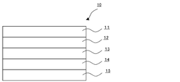
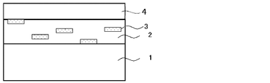
- FIG. 1 is a schematic view showing an example of the heat ray shielding material of the present invention.
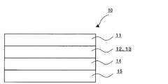
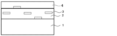
- FIG. 2 is a schematic view showing another example of the heat ray shielding material of the present invention.
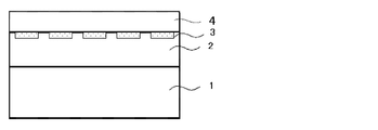
- FIG. 3 is a schematic view showing another example of the heat ray shielding material of the present invention.
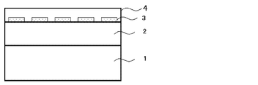
- FIG. 4 is a schematic view showing another example of the heat ray shielding material of the present invention.
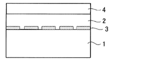
- FIG. 5A is a schematic cross-sectional view showing an example of the existence state of a metal particle-containing layer containing hexagonal or circular plate-like metal particles in the heat ray shielding material of the present invention.
- FIG. 5A is a schematic cross-sectional view showing an example of the existence state of a metal particle-containing layer containing hexagonal or circular plate-like metal particles in the heat ray shielding material of the present invention.
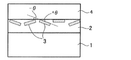
- FIG. 5B is a schematic cross-sectional view showing the existence state of a metal particle-containing layer containing hexagonal or circular flat metal particles in the heat ray shielding material of the present invention, and is a hexagonal or circular flat metal.
- FIG. 5C is a schematic cross-sectional view showing the existence state of a metal particle-containing layer containing hexagonal or circular plate-like metal particles in the heat ray-shielding material of the present invention, and shows the heat ray-shielding material of the metal particle-containing layer. It is a figure which shows the presence area
- FIG. 5D is a schematic cross-sectional view showing another example of the existence state of the metal particle-containing layer containing hexagonal or circular plate-like metal particles in the heat ray shielding material of the present invention.
- FIG. 5E is a schematic cross-sectional view showing another example of the existence state of the metal particle-containing layer containing hexagonal or circular plate-like metal particles in the heat ray shielding material of the present invention.
- FIG. 5F is a schematic cross-sectional view showing another example of the existence state of the metal particle-containing layer containing hexagonal or circular plate-like metal particles in the heat ray shielding material of the present invention.
- FIG. 5G is a schematic cross-sectional view showing another example of the presence state of the metal particle-containing layer containing hexagonal or circular plate-like metal particles in the heat ray shielding material of the present invention.
- FIG. 6A is a schematic perspective view showing an example of the shape of a flat metal particle contained in the heat ray shielding material of the present invention, and shows a circular flat metal particle.
- FIG. 6B is a schematic perspective view showing an example of the shape of the flat metal particles contained in the heat ray shielding material of the present invention, and shows hexagonal flat metal particles.
- a numerical range represented by using “to” means a range including numerical values described before and after “to” as a lower limit value and an upper limit value.
- the heat ray shielding material of the present invention has a metal particle-containing layer containing at least one kind of metal particles, and an overcoat layer disposed in close contact with at least one surface of the metal particle-containing layer.
- it has 60% by number or more of hexagonal or circular flat metal particles, and the main plane of the hexagonal or circular flat metal particles has an average of 0 with respect to one surface of the metal particle-containing layer. It is characterized in that it is oriented in the range of ° to ⁇ 30 °, and the overcoat layer contains fine particles.
- the heat ray shielding material of the present invention has good adhesion failure resistance and scratch resistance and low haze.
- the haze of the heat ray shielding material of the present invention is preferably 3% or less from the viewpoint of improving appearance and visibility, more preferably 2.5% or less, and particularly preferably 2.2% or less. .
- the haze exceeds 20%, it may be unfavorable in terms of safety, for example, it may be difficult to see the outside when used as glass for automobiles or glass for buildings.
- the solar radiation reflectance of the heat ray shielding material of the present invention preferably has a maximum value in the range of 600 nm to 2,000 nm (preferably 800 nm to 1,800 nm) from the viewpoint that the efficiency of the heat ray reflectance can be increased. .
- the visible light transmittance of the heat ray shielding material of the present invention is preferably 60% or more, more preferably 65% or more, and particularly preferably 70% or more. When the visible light transmittance is less than 60%, for example, when used as automotive glass or building glass, the outside may be difficult to see.
- the ultraviolet ray transmittance of the heat ray shielding material of the present invention is preferably 5% or less, more preferably 2% or less. When the ultraviolet transmittance exceeds 5%, the color of the metal particle-containing layer may change due to ultraviolet rays of sunlight.
- the heat ray shielding material of the present invention preferably has an embodiment having other layers such as an adhesive layer, an ultraviolet absorption layer, a base material, and a metal oxide particle-containing layer as necessary.
- the heat ray shielding material 10 has a metal particle-containing layer 14 containing at least one metal particle, an overcoat layer 13, and the overcoat layer 13.
- fine-particles is mentioned.
- a base material 15 a metal particle-containing layer 14 on the base material, an overcoat layer 13 on the metal particle-containing layer, and an ultraviolet absorbing layer 12 on the overcoat layer,
- the aspect which has the adhesion layer 11 on this ultraviolet absorption layer is mentioned.
- FIG. 3 it has the overcoat layer 13 which functions also as the ultraviolet absorption layer 12 and the adhesion layer 11, the base material 15, the metal particle containing layer 14 on this base material, and this metal particle containing
- the overcoat layer 13 which functions also as the ultraviolet absorption layer 12 and the adhesion layer 11 on a layer is mentioned suitably.
- FIG. 4 it has an overcoat layer 13 that also functions as the ultraviolet absorption layer 12, a base material 15, a metal particle-containing layer 14 on the base material, and an ultraviolet ray on the metal particle-containing layer.
- an embodiment in which the overcoat layer 13 that also functions as the absorption layer 12 and the adhesive layer 11 on the overcoat layer 13 that also functions as the ultraviolet absorption layer 12 is preferably exemplified.
- the overcoat layer 13 containing fine particles as shown in FIGS. 1 to 4 hexagonal or circular plate-like metal particles contained in the metal particle-containing layer can be appropriately formed.
- scratch resistance can be imparted. This effect is particularly remarkable when the flat metal particles are segregated on the surface of the metal particle-containing layer on the overcoat layer side.
- the state wound up by roll shape may be sufficient. Since the heat ray shielding material of the present invention has good adhesion failure resistance, there are few failures when stacking the heat ray shielding materials of a plurality of the present invention in the case of a sheet, and it is wound up in a roll shape. Is less squeaky. In the case where the heat ray shielding material of the present invention is wound into a roll, it is preferably wound around a core having a diameter of 50 to 250 mm. The heat ray shielding material of the present invention preferably has good adhesion failure resistance in the range of 2 to 20 kg / cm 2 .
- Metal particle-containing layer is a layer containing at least one type of metal particles, and the metal particles have hexagonal or circular plate-like metal particles of 60% by number or more, and the hexagonal shape.
- the main plane of the flat metal particle having a circular shape is plane-oriented in an average range of 0 ° to ⁇ 30 ° with respect to one surface of the metal particle-containing layer.
- the flat metal particles can be segregated on one surface of the metal particle-containing layer.
- Metal particles have 60% by number or more of hexagonal or circular tabular metal particles, and the main plane of the hexagonal or circular tabular metal particles is on one surface of the metal particle-containing layer. On the other hand, there is no particular limitation as long as the plane orientation is in the range of 0 ° to ⁇ 30 ° on average, and it can be appropriately selected according to the purpose.
- the thickness of the metal particle-containing layer is d, it is preferable that 80% by number or more of the hexagonal or circular tabular metal particles exist in a range of d / 2 from the surface of the metal particle-containing layer. , D / 3 is more preferable.
- the metal particle-containing layer hexagonal to circular plate-like metal particles are present as one surface of the metal particle-containing layer (the surface of the substrate when the heat ray shielding material of the present invention has a substrate).
- the plane orientation is in the range of 0 ° to ⁇ 30 ° on the average.
- the hexagonal or circular plate-like metal particles have 80% by number or more of the hexagonal or circular plate-like metal particles of the metal particle-containing layer. It is preferable that it exists in the range of d / 2 from the surface, and it is more preferable that it exists in the range of d / 3.
- one surface of the said metal particle content layer is a flat plane.
- the metal particle-containing layer of the heat ray shielding material of the present invention has a base material as a temporary support, it is preferably substantially horizontal with the surface of the base material.
- the said heat ray shielding material may have the said temporary support body, and does not need to have it.
- size of the said metal particle According to the objective, it can select suitably, For example, you may have an average particle diameter of 500 nm or less.
- the material of the metal particles is not particularly limited and can be appropriately selected according to the purpose. From the viewpoint of high heat ray (near infrared) reflectance, silver, gold, aluminum, copper, rhodium, nickel, Platinum or the like is preferable.
- the flat metal particles are not particularly limited as long as they are particles composed of two main planes (see FIGS. 6A and 6B), and can be appropriately selected according to the purpose.
- hexagonal shape, circular shape examples include a triangle shape.
- a polygonal shape or a circular shape having a hexagonal shape or more is more preferable, and a hexagonal shape or a circular shape is particularly preferable.
- the circular shape means a shape in which the number of sides having a length of 50% or more of the average equivalent circle diameter of the flat metal particles described later is 0 per flat metal particle.
- the circular plate-like metal particles are not particularly limited as long as the plate-like metal particles have no corners and are round when viewed from above the main plane with a transmission electron microscope (TEM). It can be appropriately selected depending on the case.
- the hexagonal shape refers to a shape in which the number of sides having a length of 20% or more of the average equivalent circle diameter of the flat metal particles described later is 6 per flat metal particle. To tell. The same applies to other polygons.
- the hexagonal plate-like metal particles are not particularly limited as long as they are hexagonal when the plate-like metal particles are observed from above the main plane with a transmission electron microscope (TEM), and are appropriately selected according to the purpose.
- the hexagonal corner may be acute or dull, but the corner is preferably dull in that the absorption in the visible light region can be reduced.
- limiting in particular as a grade of the dullness of an angle According to the objective, it can select suitably.
- limiting in particular as a material of the said flat metal particle The same thing as the said metal particle can be suitably selected according to the objective.
- the flat metal particles preferably contain at least silver.
- hexagonal or circular plate-like metal particles are 60% by number or more, preferably 65% by number or more, and 70 by number with respect to the total number of metal particles. % Or more is more preferable. If the proportion of the flat metal particles is less than 60% by number, the visible light transmittance may be lowered.
- the hexagonal or circular plate-like metal particles have a main plane on one surface of the metal particle-containing layer (when the heat ray shielding material has a substrate, the surface of the substrate).
- it is plane-oriented in an average range of 0 ° to ⁇ 30 °, preferably plane-oriented in an average range of 0 ° to ⁇ 20 °, and plane-oriented in an average range of 0 ° to ⁇ 10 °. It is particularly preferable.
- the presence state of the flat metal particles is not particularly limited and may be appropriately selected depending on the purpose, but is preferably arranged as shown in FIGS. 5F and 5G described later.
- FIG. 5D to FIG. 5F, FIG. 5B and FIG. 5C are schematic cross-sectional views showing the existence state of the metal particle-containing layer containing flat metal particles in the heat ray shielding material of the present invention.
- FIGS. 5D to 5F show the state of the presence of the flat metal particles 3 in the metal particle-containing layer 2.
- FIG. 5B is a diagram for explaining an angle ( ⁇ ⁇ ) formed by the plane of the substrate 1 and the plane of the flat metal particles 3.
- FIG. 5C shows the existence region in the depth direction of the heat ray shielding material of the metal particle-containing layer 2.
- the angle ( ⁇ ⁇ ) formed by the surface of the substrate 1 and the main plane of the tabular metal particles 3 or an extension line of the main plane corresponds to a predetermined range in the plane orientation. That is, the plane orientation means a state where the inclination angle ( ⁇ ⁇ ) shown in FIG. 5B is small when the cross section of the heat ray shielding material is observed.
- FIG. 5F shows the surface of the substrate 1 and the flat metal particles 3. A state where the main plane is in contact, that is, a state where ⁇ is 0 ° is shown.
- a predetermined wavelength for example, from the visible light region long wavelength side
- the reflectance in the near infrared light region will be reduced.
- the main plane of the flat metal particles is plane-oriented with respect to one surface of the metal particle-containing layer (the surface of the substrate when the heat ray shielding material has a substrate)
- the surface of the substrate when the heat ray shielding material has a substrate there is no particular limitation.
- a suitable cross section is prepared, and a metal particle-containing layer (a base material when the heat ray shielding material has a base material) and flat metal particles in this section It may be a method of observing and evaluating.
- a microtome or a focused ion beam is used to prepare a cross-section sample or a cross-section sample of the heat ray shielding material, and this is used for various microscopes (for example, a field emission scanning electron microscope (FE-SEM) etc.), and a method of evaluating from an image obtained by observation.
- FE-SEM field emission scanning electron microscope
- the cross-section sample or the cross-section section is obtained by cutting a sample frozen in liquid nitrogen by a diamond cutter attached to a microtome. A sample may be made.
- covers a flat metal particle in a heat ray shielding material does not swell with water, you may produce the said cross-section sample or a cross-section piece sample.
- the surface of the metal particle-containing layer in the sample (the surface of the base material when the heat ray shielding material has a base material)
- the surface of the metal particle-containing layer in the sample there is no particular limitation as long as it can confirm whether or not the main plane is plane-oriented, and it can be appropriately selected according to the purpose.
- observation using an FE-SEM, TEM, optical microscope, etc. Can be mentioned.
- observation may be performed by FE-SEM
- observation may be performed by TEM.
- the average particle diameter (average equivalent circle diameter) of the flat metal particles is not particularly limited and may be appropriately selected depending on the intended purpose, but is preferably 70 nm to 500 nm, and more preferably 100 nm to 400 nm.
- the average particle diameter (average equivalent circle diameter) is less than 70 nm, the contribution of the absorption of the flat metal particles may be larger than the reflection, so that sufficient heat ray reflectivity may not be obtained.
- the haze (scattering) increases and the transparency of the substrate may be impaired.
- the average particle diameter means an average value of main plane diameters (maximum lengths) of 200 tabular grains arbitrarily selected from images obtained by observing grains with a TEM. To do. Two or more kinds of metal particles having different average particle diameters (average circle equivalent diameters) can be contained in the metal particle-containing layer. In this case, the peak of the average particle diameter (average circle equivalent diameter) of the metal particles is 2 It may have two or more, that is, two or more average particle diameters (average circle equivalent diameter).
- the coefficient of variation in the particle size distribution of the flat metal particles is preferably 30% or less, more preferably 20% or less. When the coefficient of variation exceeds 30%, the reflection wavelength region of the heat ray in the heat ray shielding material may become broad.
- the coefficient of variation in the particle size distribution of the flat metal particles is, for example, a plot of the particle diameter distribution range of the 200 flat metal particles used for calculating the average value obtained as described above, and a standard particle size distribution. The deviation is obtained, and is a value (%) divided by the average value (average particle diameter (average equivalent circle diameter)) of the main plane diameter (maximum length) obtained as described above.
- the aspect ratio of the flat metal particles is not particularly limited and may be appropriately selected depending on the intended purpose. However, since the reflectance in the infrared light region having a wavelength of 780 nm to 1,800 nm is increased, 8 ⁇ 40 are preferred, and 10 to 35 are more preferred. When the aspect ratio is less than 8, the reflection wavelength becomes smaller than 780 nm, and when it exceeds 40, the reflection wavelength becomes longer than 1,800 nm, and sufficient heat ray reflectivity may not be obtained.
- the aspect ratio means a value obtained by dividing the average particle diameter (average circle equivalent diameter) of the flat metal particles by the average particle thickness of the flat metal particles.
- the average grain thickness corresponds to the distance between the main planes of the flat metal particles, and is as shown in FIGS. 6A and 6B, for example, and can be measured by an atomic force microscope (AFM).
- the method for measuring the average particle thickness by the AFM is not particularly limited and can be appropriately selected according to the purpose. For example, a particle dispersion containing tabular metal particles is dropped onto a glass substrate and dried. And a method of measuring the thickness of one particle.
- the thickness of the flat metal particles is preferably 5 to 20 nm.
- the plasmon resonance wavelength ⁇ of the metal constituting the flat metal particle in the metal particle-containing layer is not particularly limited and can be appropriately selected according to the purpose. However, in terms of imparting heat ray reflection performance, 400 nm to 2 nm. , 500 nm is preferable, and from the viewpoint of imparting visible light transmittance, 700 nm to 2,500 nm is more preferable.
- the metal-containing layer preferably contains a polymer, and more preferably contains a transparent polymer.
- the polymer include polyvinyl acetal resin, polyvinyl alcohol resin, polyvinyl butyral resin, polyacrylate resin, polymethyl methacrylate resin, polycarbonate resin, polyvinyl chloride resin, (saturated) polyester resin, polyurethane resin, gelatin resin and cellulose. And polymers such as natural polymers.
- the main polymer of the polymer is preferably a polyvinyl alcohol resin, a polyvinyl butyral resin, a polyvinyl chloride resin, a (saturated) polyester resin, a polyurethane resin, and preferably the polyester resin and the polyurethane resin. More preferably, 80% by number or more of hexagonal or circular plate-like metal particles are present in the range of d / 2 from the surface of the metal particle-containing layer, and the heat ray shielding material of the present invention is a polyester resin. It is particularly preferable from the viewpoint of further improving the resistance to rubbing.
- the main polymer of the polymer contained in the metal-containing layer refers to a polymer component occupying 50% by mass or more of the polymer contained in the metal-containing layer.
- the refractive index n of the medium is preferably 1.4 to 1.7.
- n of the medium is preferably 1.4 to 1.7.
- the thickness of the hexagonal or circular plate-like metal particles is a
- 80% or more of the hexagonal or circular plate-like metal particles are a / in the thickness direction. It is preferable that 10 or more is covered with the polymer, a / 10 to 10a in the thickness direction is more preferably covered with the polymer, and a / 8 to 4a is covered with the polymer. Particularly preferred.
- the hexagonal or circular plate-like metal particles are buried in the metal particle-containing layer at a certain ratio or more, whereby the rubbing resistance can be further increased. That is, the heat ray shielding material of the present invention is preferably in the mode of FIG. 5F rather than the mode of FIG. 5G.
- the area ratio of flat metal particles The area of the flat metal particles with respect to the area A of the base material when the heat ray shielding material is viewed from above (the total projected area A of the metal particle-containing layer when viewed from the direction perpendicular to the metal particle-containing layer)
- the area ratio [(B / A) ⁇ 100] which is the ratio of the total value B, is preferably 15% or more, and more preferably 20% or more.
- the area ratio can be measured, for example, by performing image processing on an image obtained by SEM observation of the heat ray shielding base material from above or an image obtained by AFM (atomic force microscope) observation. .
- the average inter-particle distance between the tabular metal particles adjacent in the horizontal direction in the metal particle-containing layer is 1/10 or more of the average particle diameter of the tabular metal particles from the viewpoint of visible light transmittance and maximum heat ray reflectance. Is preferred.
- the average inter-particle distance in the horizontal direction of the flat metal particles is less than 1/10 of the average particle diameter of the flat metal particles, the visible light transmittance is lowered. On the other hand, if it is 10 or more, the heat ray reflectance is lowered.
- the average interparticle distance in the horizontal direction is preferably non-uniform (random) in terms of visible light transmittance. If it is not random, that is, if it is uniform, moire fringes may be seen due to diffraction scattering.
- the average inter-particle distance in the horizontal direction of the flat metal particles means an average value of inter-particle distances between two adjacent particles.
- the average inter-particle distance is random as follows: “When the two-dimensional autocorrelation of the luminance value when binarizing an SEM image including 100 or more tabular metal particles is taken, Does not have a significant local maximum. "
- the flat metal particles are arranged in the form of a metal particle-containing layer containing flat metal particles, as shown in FIGS. 5B, 5C, and 5D to 5F.
- the metal particle-containing layer may be composed of a single layer as shown in FIGS. 5B, 5C, and 5D to 5F, or may be composed of a plurality of metal particle-containing layers. When comprised with a several metal particle content layer, it becomes possible to provide the shielding performance according to the wavelength range
- Thickness of metal particle containing layer The thickness d of the metal particle-containing layer preferably satisfies a / 2 ⁇ d ⁇ 2b, where a is the thickness of the metal particles and b is the average particle diameter (average equivalent circle diameter). It is more preferable to satisfy d ⁇ b. If d is too thin, the metal particle-containing layer will be difficult to hold the metal particles, and the metal particles will be easily peeled off during stacking and transporting. Conversely, if d is too thick, the metal particles will contain metal particles. It becomes difficult to be unevenly distributed on the surface of the layer.
- the thickness of each layer of the metal particle-containing layer can be measured, for example, from an image obtained by SEM observation of a cross-sectional sample of the heat ray shielding material.
- the boundary between the other layer and the metal particle-containing layer is determined by the same method.
- the thickness d of the metal particle-containing layer can be determined.
- it is difficult to determine the boundary with the metal particle-containing layer. By coating the overcoat layer after carbon deposition on the containing layer and observing the cross section with an SEM, the interface between the two layers can be recognized, and the thickness d of the metal particle containing layer can be determined. it can.
- the method for synthesizing the flat metal particles is not particularly limited as long as it can synthesize hexagonal to circular flat metal particles, and can be appropriately selected according to the purpose.
- a chemical reduction method And liquid phase methods such as a photochemical reduction method and an electrochemical reduction method.
- a liquid phase method such as a chemical reduction method or a photochemical reduction method is particularly preferable in terms of shape and size controllability.
- the metal particles for example, Ag
- the metal particles may be crystal-grown in a flat shape.
- the flat metal particles may be subjected to further treatment in order to impart desired characteristics.
- the further treatment is not particularly limited and may be appropriately selected depending on the purpose.
- the formation of a high refractive index shell layer the addition of various additives such as a dispersant and an antioxidant may be included. Can be mentioned.
- the flat metal particles may be coated with a high refractive index material having high visible light region transparency in order to further enhance visible light region transparency.
- a high refractive index material is not particularly limited and may be appropriately selected depending on the purpose, for example, TiO x, BaTiO 3, ZnO, etc. SnO 2, ZrO 2, NbO x and the like.
- an SiO 2 or polymer shell layer is appropriately formed. Further, the metal oxide layer may be formed on the shell layer.
- TiO x is used as a material for the high refractive index metal oxide layer, since TiO x has photocatalytic activity, there is a concern that the matrix in which the plate-like metal particles are dispersed may be deteriorated. After the TiO x layer is formed on the flat metal particles, an SiO 2 layer may be appropriately formed.
- the flat metal particles may adsorb an antioxidant such as mercaptotetrazole or ascorbic acid in order to prevent oxidation of metals such as silver constituting the flat metal particles.
- an oxidation sacrificial layer such as Ni may be formed on the surface of the flat metal particles. Further, it may be covered with a metal oxide film such as SiO 2 for the purpose of blocking oxygen.
- the flat metal particles are, for example, a low molecular weight dispersant, a high molecular weight dispersant or the like containing at least one of an N element such as a quaternary ammonium salt and amines, an S element, and a P element.
- a dispersant may be added.
- the heat ray shielding material of the present invention has an overcoat layer disposed in close contact with the surface of the metal particle-containing layer, and the overcoat layer contains fine particles.
- the heat ray shielding material of the present invention has an overcoat layer, particularly when tabular metal particles are unevenly distributed on the surface of the metal particle-containing layer, preventing contamination of the manufacturing process due to stripping of the tabular metal particles, when applying another layer It is possible to prevent the disorder of the arrangement of the flat metal particles.
- the fine particles may be inorganic fine particles or organic fine particles, but are preferably inorganic fine particles.
- the inorganic fine particles include oxides (for example, colloidal silica, titanium oxide, magnesium oxide, aluminum oxide), alkaline earth metal salts (for example, sulfates and carbonates, specifically, barium sulfate, carbonates). Calcium, magnesium sulfate, strontium sulfate, calcium carbonate, etc.), silver halide grains and glass that do not form an image.
- Inorganic particles described in US Pat. Nos. 4,021,245 and 4,029,504 can also be used.
- colloidal silica, titanium oxide, barium sulfate, silver halide and the like are preferable, and colloidal silica is particularly preferable.
- colloidal silica include E.I. I. du ponte de Nemours & Co.
- Ludox AM Ludox AM
- Ludox AS Ludox AS
- Ludox LS Ludox HS
- Nissan Chemical Co., Ltd. Tokyo, Japan
- Snowtex 20 Snowtex C
- Snowtex N Snowtex N
- Snowtex O etc.
- Monsanto Co. USA
- Syton C-30 Syton-200
- Nalco Chem. Co. USA
- a tin dioxide-antimony composite acicular metal oxide aqueous dispersion commercially available from Ishihara Sangyo under the product name FS-10D can also be used.
- a water-dispersed polymer (latex) is preferably used.
- an ester of acrylic acid or methacrylic acid particularly methyl, ethyl, n-propyl, isopropyl, n-butyl, isobutyl, t-butyl, hexyl
- Polymers containing an alkyl group having 1 to 10 carbon atoms such as 2-ethylhexyl, heptyl, n-octyl or the like and unsaturated carboxylic acid components such as acrylic acid, methacrylic acid, fumaric acid, itaconic acid, maleic acid And acrylonitrile, methacrylonitrile, halogen-substituted acrylonitrile, halogen-substituted methacrylonitrile, acrylamide, methacrylamide, N-methylol acrylonitrile, N-ethanol acrylamide, N-methyl acrylamide, N-propanol acryl Mido, N-methylolmethacrylamide, Nt-butylacrylamide,
- vinyl esters such as vinyl acetate, vinyl chloroacetate, and vinyl benzoate, vinyl pyridine, vinyl chloride, and butadiene.
- These water-dispersed polymers can be obtained by dispersing a mixture of these monomers in water using a surfactant and then polymerizing with a normal radical initiator.
- the average particle diameter of the fine particles is preferably 5 to 1500 nm, more preferably 5 to 900 nm, and particularly preferably 5 to 300 nm.
- the average particle diameter of the fine particles is preferably 5 to 1500 nm, more preferably 5 to 900 nm, and particularly preferably 5 to 300 nm.
- the mass ratio of the fine particles to the binder in the overcoat layer is preferably 0.02 to 0.4, more preferably 0.02 to 0.3, and 0.02 to 0.2. It is particularly preferred that
- the overcoat layer is not particularly limited except that it contains fine particles, and can be appropriately selected according to the purpose.
- Examples of the overcoat layer include binders, matting agents, cross-linking agents, slip agents, and surface antifouling agents. Further, it contains a refractive index adjusting agent and a surfactant, and may further contain other components as necessary.
- the binder is not particularly limited and may be appropriately selected depending on the purpose. For example, thermosetting of acrylic resin, silicone resin, melamine resin, urethane resin, alkyd resin, fluorine resin, etc. Mold or photo-curable resin. Moreover, the binder illustrated in the said ultraviolet absorption layer can be used. Moreover, you may further provide the function as an overcoat layer to functional layers, such as the below-mentioned ultraviolet absorption layer, an adhesion layer, and a hard-coat layer.
- the thickness of the overcoat layer is preferably 100 to 2000 nm, more preferably 100 to 2000 nm, and particularly preferably 150 to 2000 nm.
- a thin film of about 100 nm is usually preferred in consideration of the amount of material used and the surface roughness.
- the thickness is preferably 150 nm or more. However, this is not the case when the refractive indexes of the adhesive layer and the overcoat layer are matched.
- bar coating is advantageous to reduce the manufacturing cost, it is preferable to set the dry thickness of the overcoat layer to 2000 nm or less in consideration of the general viscosity and wet coating amount.
- the heat ray shielding material of the present invention preferably further has a base material on the surface of the metal particle-containing layer opposite to the surface on which the overcoat layer is disposed.
- the substrate is not particularly limited as long as it is an optically transparent substrate, and can be appropriately selected according to the purpose.
- the substrate has a visible light transmittance of 70% or more, preferably 80% or more. And those with high transmittance in the near infrared region.
- the shape examples include a flat plate shape, and the structure may be a single layer structure or a laminated structure, and the size may be the size of the heat ray shielding material. It can be appropriately selected according to the above.
- the material for the substrate is not particularly limited and may be appropriately selected depending on the intended purpose.
- polyolefin resins such as polyethylene, polypropylene, poly-4-methylpentene-1, polybutene-1, polyethylene terephthalate
- Polyester resins such as polyethylene naphthalate
- polycarbonate resins polyvinyl chloride resins
- polyphenylene sulfide resins polyether sulfone resins
- polyethylene sulfide resins polyphenylene ether resins
- styrene resins acrylic resins
- polyamides examples thereof include a film made of a cellulose resin such as a cellulose resin, a polyimide resin, and cellulose acetate, or a laminated film thereof.
- a polyethylene terephthalate film is particularly preferable.
- the thickness of the base material is not particularly limited and can be appropriately selected according to the purpose of use of the solar shading film. Usually, the thickness is about 10 ⁇ m to 500 ⁇ m, but the thinner one is preferable from the viewpoint of thinning. preferable.
- the thickness of the substrate is preferably 10 ⁇ m to 100 ⁇ m, more preferably 20 to 75 ⁇ m, and particularly preferably 35 to 75 ⁇ m.
- the thickness of the base material is reduced, the strength as a heat ray shielding material is insufficient, or adhesion failure tends to occur.
- fine particles having a preferred particle size defined in the present invention for the overcoat layer adhesion failure can be reduced even when a thin substrate is used.
- the said base material becomes thick, when it bonds together to a building material and a motor vehicle as a heat ray shielding material, there exists a tendency for the waist as a material to be strong and to become difficult to construct. Furthermore, since the base material is thick, the visible light transmittance tends to decrease and the raw material cost tends to increase.
- the heat ray shielding material of the present invention may further include a metal oxide particle-containing layer containing at least one metal oxide particle as a layer that absorbs long-wave infrared rays. From the viewpoint of balance, it is preferable.
- the metal oxide particle-containing layer is a surface of the metal particle-containing layer on which the hexagonal or circular plate-like metal particles of the metal particle-containing layer are exposed. It is preferable to have on the opposite surface side. In this case, for example, the metal oxide particle-containing layer may be laminated with the metal particle-containing layer via a base material.
- the heat ray shielding material of the present invention when the heat ray shielding material of the present invention is disposed so that the metal particle-containing layer 2 is on the incident direction side of heat rays such as sunlight, a part of the heat rays (or the metal particle-containing layer (or After reflection, all of the heat rays are absorbed by the metal oxide-containing layer, and the inside of the heat-ray shielding material is caused by the heat rays that are not absorbed by the metal particle-containing layer and pass through the heat ray shielding material. It is possible to reduce the amount of heat received directly at the heat amount and the total amount of heat absorbed by the metal oxide-containing layer of the heat ray shielding material and indirectly transmitted to the inside of the heat ray shielding material.
- the said metal oxide particle content layer is a layer containing at least 1 sort (s) of metal oxide particle, there will be no restriction
- limiting in particular as a material of the said metal oxide particle According to the objective, it can select suitably, For example, a tin dope indium oxide (henceforth "ITO”), a tin dope antimony oxide (henceforth). , Abbreviated as “ATO”), zinc oxide, titanium oxide, indium oxide, tin oxide, antimony oxide, glass ceramics, and the like.
- ITO, ATO, and zinc oxide are more preferable, and infrared rays having a wavelength of 1,200 nm or more are 90% in that they have excellent heat ray absorption ability and can produce heat ray shielding materials having a wide range of heat ray absorption ability when combined with silver tabular grains.
- ITO is preferable in that it has a visible light transmittance of 90% or more.
- the volume average particle size of the primary particles of the metal oxide particles is preferably 0.1 ⁇ m or less in order not to reduce the visible light transmittance.
- limiting in particular as a shape of the said metal oxide particle According to the objective, it can select suitably, For example, spherical shape, needle shape, plate shape, etc. are mentioned.
- the content of the metal oxide particles in the metal oxide particle-containing layer is not particularly limited and may be appropriately selected depending on the purpose, but is preferably 0.1 g / m 2 to 20 g / m 2 , 0.5 g / m 2 to 10 g / m 2 is more preferable, and 1.0 g / m 2 to 4.0 g / m 2 is more preferable. If the content is less than 0.1 g / m 2 , the amount of solar radiation felt on the skin may increase, and if it exceeds 20 g / m 2 , the visible light transmittance may deteriorate.
- the content of the metal oxide particles in the metal oxide particle-containing layer is, for example, from the observation of the super foil section TEM image and surface SEM image of the heat ray shielding layer, and the number of metal oxide particles in a certain area and It can be calculated by measuring the average particle diameter and dividing the mass (g) calculated based on the number and average particle diameter and the specific gravity of the metal oxide particles by the constant area (m 2 ). .
- metal oxide fine particles in a certain area of the metal oxide particle-containing layer are eluted in methanol, and the mass (g) of the metal oxide fine particles measured by fluorescent X-ray measurement is divided by the constant area (m 2 ). This can also be calculated.
- the ultraviolet absorbing layer is not particularly limited as long as it is a layer containing at least one ultraviolet absorber, and can be appropriately selected according to the purpose, and may be an adhesive layer. It may be a layer (for example, an overcoat layer, a base material, an intermediate layer other than these) between the adhesive layer and the metal particle-containing layer. In any case, it is preferable that the ultraviolet absorbing layer is disposed on the side irradiated with sunlight with respect to the metal particle-containing layer. In the case where the ultraviolet absorbing layer forms an intermediate layer that is neither an adhesive layer nor a substrate, the ultraviolet absorbing layer contains at least one ultraviolet absorber, and, if necessary, a binder or the like Of other ingredients.
- the heat ray shielding material of the present invention preferably has an ultraviolet absorbing layer on the surface side of the metal particle-containing layer where the hexagonal or circular flat metal particles are exposed.
- the overcoat layer and the ultraviolet absorbing layer described later may be the same or different.
- the overcoat layer is a layer between the ultraviolet absorption layer and the metal particle-containing layer, and the overcoat layer is the ultraviolet absorption layer. It is also preferable.
- UV absorbers The ultraviolet absorber is not particularly limited and may be appropriately selected depending on the purpose. For example, a benzophenone ultraviolet absorber, a benzotriazole ultraviolet absorber, a triazine ultraviolet absorber, a salicylate ultraviolet absorber, Examples include cyanoacrylate ultraviolet absorbers. These may be used individually by 1 type and may use 2 or more types together.
- the benzophenone-based ultraviolet absorber is not particularly limited and may be appropriately selected depending on the intended purpose. Examples thereof include 2,4droxy-4-methoxy-5-sulfobenzophenone.
- the benzotriazole ultraviolet absorber is not particularly limited and may be appropriately selected depending on the intended purpose.
- the triazine ultraviolet absorber is not particularly limited and may be appropriately selected depending on the intended purpose. Examples thereof include mono (hydroxyphenyl) triazine compounds, bis (hydroxyphenyl) triazine compounds, and tris (hydroxyphenyl) triazine compounds. Etc. Examples of the mono (hydroxyphenyl) triazine compound include 2- [4-[(2-hydroxy-3-dodecyloxypropyl) oxy] -2-hydroxyphenyl] -4,6-bis (2,4-dimethyl).
- Phenyl) -1,3,5-triazine 2- [4-[(2-hydroxy-3-tridecyloxypropyl) oxy] -2-hydroxyphenyl] -4,6-bis (2,4-dimethylphenyl) ) -1,3,5-triazine, 2- (2,4-dihydroxyphenyl) -4,6-bis (2,4-dimethylphenyl) -1,3,5-triazine, 2- (2-hydroxy- 4-isooctyloxyphenyl) -4,6-bis (2,4-dimethylphenyl) -1,3,5-triazine, 2- (2-hydroxy-4-dodecyloxyphenyl) -4,6-bis ( 2,4-dimethylphenyl) -1,3,5-triazine, etc.
- Examples of the bis (hydroxyphenyl) triazine compound include 2,4-bis (2-hydroxy-4-propyloxyphenyl) -6- (2,4-dimethylphenyl) -1,3,5-triazine, 2 , 4-Bis (2-hydroxy-3-methyl-4-propyloxyphenyl) -6- (4-methylphenyl) -1,3,5-triazine, 2,4-bis (2-hydroxy-3-methyl) -4-hexyloxyphenyl) -6- (2,4-dimethylphenyl) -1,3,5-triazine, 2-phenyl-4,6-bis [2-hydroxy-4- [3- (methoxyheptaethoxy ) -2-hydroxypropyloxy] phenyl] -1,3,5-triazine and the like.
- tris (hydroxyphenyl) triazine compound examples include 2,4-bis (2-hydroxy-4-butoxyphenyl) -6- (2,4-dibutoxyphenyl) -1,3,5-triazine, 2 , 4,6-Tris (2-hydroxy-4-octyloxyphenyl) -1,3,5-triazine, 2,4,6-tris [2-hydroxy-4- (3-butoxy-2-hydroxypropyloxy) ) Phenyl] -1,3,5-triazine, 2,4-bis [2-hydroxy-4- [1- (isooctyloxycarbonyl) ethoxy] phenyl] -6- (2,4-dihydroxyphenyl) -1 , 3,5-triazine, 2,4,6-tris [2-hydroxy-4- [1- (isooctyloxycarbonyl) ethoxy] phenyl] -1,3,5-triazine, 2,4-bis [2 -Hydroxy-4
- the salicylate-based ultraviolet absorber is not particularly limited and may be appropriately selected depending on the intended purpose. Examples thereof include phenyl salicylate, p-tert-butylphenyl salicylate, p-octylphenyl salicylate, Examples include 2-ethylhexyl salicylate.
- the cyanoacrylate-based ultraviolet absorber is not particularly limited and may be appropriately selected depending on the intended purpose.
- binder- The binder used in the ultraviolet absorbing layer is not particularly limited and may be appropriately selected depending on the purpose, but preferably has higher visible light transparency and higher solar transparency, such as acrylic resin, polyvinyl butyral, Examples include polyvinyl alcohol.
- the ultraviolet absorbing layer formed between the heat ray source and the flat metal particles has a wavelength range of 450 nm to 1,500 nm. It is preferable to select a material that does not absorb light or to reduce the thickness of the ultraviolet absorbing layer.
- the thickness of the ultraviolet absorbing layer is preferably 0.01 ⁇ m to 1,000 ⁇ m, more preferably 0.02 ⁇ m to 500 ⁇ m.
- the absorption of ultraviolet rays may be insufficient, and when it exceeds 1,000 ⁇ m, the visible light transmittance may decrease.
- the content of the ultraviolet absorbing layer varies depending on the ultraviolet absorbing layer to be used and cannot be generally defined, but it is preferable to appropriately select a content that gives a desired ultraviolet transmittance in the heat ray shielding material of the present invention.
- the ultraviolet transmittance is preferably 5% or less, and more preferably 2% or less. When the ultraviolet transmittance exceeds 5%, the color of the metal particle-containing layer may change due to ultraviolet rays of sunlight.
- the heat ray shielding material of the present invention preferably has an adhesive layer.
- the adhesive layer may be the overcoat layer, an adhesive layer having the function of the ultraviolet absorbing layer, or an adhesive layer not containing the ultraviolet absorber.
- the material that can be used for forming the adhesive layer is not particularly limited and may be appropriately selected depending on the intended purpose.
- An adhesive layer made of these materials can be formed by coating.
- an antistatic agent, a lubricant, an antiblocking agent and the like may be added to the adhesive layer.
- the thickness of the adhesive layer is preferably 0.1 ⁇ m to 10 ⁇ m.
- the heat ray shielding material includes a hard coat layer having hard coat properties.
- a hard coat layer having hard coat properties.
- the kind and formation method can be selected suitably according to the objective, for example, acrylic resin, silicone resin, melamine resin, urethane resin, alkyd resin And thermosetting or photocurable resins such as fluorine-based resins.
- the thickness of the hard coat layer is not particularly limited and may be appropriately selected depending on the intended purpose, but is preferably 1 ⁇ m to 50 ⁇ m.
- the hard coat layer may contain the metal oxide particles.
- a protective layer other than the overcoat layer may be provided in order to improve the adhesion to the base material or to protect it from mechanical strength.
- a protective layer there is no restriction
- limiting in particular as said binder According to the objective, it can select suitably, The binder illustrated in the said ultraviolet absorption layer can be used.
- the method for forming the metal particle-containing layer of the present invention is not particularly limited and may be appropriately selected depending on the purpose.
- the dispersion having the flat metal particles on the surface of the lower layer such as the substrate examples include a method in which the liquid is applied by a dip coater, a die coater, a slit coater, a bar coater, a gravure coater, or the like, and a method in which the liquid is aligned by a method such as an LB film method, a self-assembly method, or a spray coating.
- the method of applying with a bar coater is preferable.
- the composition of the metal particle-containing layer used in the examples described later, the latex is added and 80% by number or more of the hexagonal or circular plate-like metal particles are It is preferable that it exists in the range of d / 2 from the surface of a metal particle content layer, and it is more preferable to exist in the range of d / 3.
- the amount of the latex added is not particularly limited, but for example, it is preferable to add 1 to 10000 mass% with respect to the flat metal particles.
- the method for forming the metal particle-containing layer includes a method in which surface orientation is performed using electrostatic interaction in order to improve the adsorptivity to the substrate surface and the surface orientation of the flat metal particles. You may go out.
- a method for example, when the surface of the flat metal particles is negatively charged (for example, dispersed in a negatively charged medium such as citric acid), the surface of the substrate is positively charged.
- the surface of the base material is modified with an amino group or the like), and the surface orientation is electrostatically enhanced to surface align.
- a hydrophilic / hydrophobic sea-island structure is formed on the surface of the base material by block copolymer, ⁇ contact stamp method, etc., and the hydrophilic / hydrophobic interaction is utilized. You may control a plane orientation and the intergranular distance of a flat metal particle.
- a pressure roller such as a calendar roller or a laminating roller.
- the method for forming the overcoat is not particularly limited as long as it contains at least one kind of the fine particles, and a known method can be appropriately selected according to the purpose, and is preferably formed by coating. .
- the coating method at this time is not particularly limited, and a known method can be used.
- a dispersion containing the ultraviolet absorber can be used as a dip coater, a die coater, a slit coater, a bar coater, a gravure coater, or the like.
- coating by etc. is mentioned. Among these, the method of applying with a bar coater is preferable.
- the overcoat layer is an adhesive layer
- the overcoat layer may be formed by adding at least one kind of fine particles in a method for forming an adhesive layer described later, and a commercial product containing the fine particles. A product adhesive layer may be used.
- a method for forming the ultraviolet absorbing layer is not particularly limited as long as it contains at least one ultraviolet absorber, and a known method can be appropriately selected according to the purpose.
- the ultraviolet absorbing layer is an adhesive layer
- the ultraviolet absorbing layer may be formed by adding at least one ultraviolet absorber in the method for forming an adhesive layer described later. You may use the commercial adhesion layer containing this.
- the ultraviolet absorbing layer is a substrate
- the ultraviolet absorbing layer may be formed by adding at least one ultraviolet absorber in the material of the substrate, and the ultraviolet absorbing layer may be formed. You may use the base material of the commercial item containing an agent.
- the commercially available products include UV-absorbing PET films such as Teijin (registered trademark) Tetron (registered trademark) film and Teijin DuPont Film Co., Ltd.
- the ultraviolet absorbing layer is an intermediate layer that is neither an adhesive layer nor a substrate
- the ultraviolet absorbing layer is preferably formed by coating.
- the coating method at this time is not particularly limited, and a known method can be used.
- a dispersion containing the ultraviolet absorber can be used as a dip coater, a die coater, a slit coater, a bar coater, a gravure coater, or the like. The method of apply
- the adhesive layer is preferably formed by coating.
- it can be laminated on the surface of the lower layer such as the base material, the metal particle-containing layer, or the ultraviolet absorbing layer.
- the coating method at this time A well-known method can be used.
- Adhesive layer lamination by dry lamination When the functionality is imparted to the existing window glass using the heat ray shielding material film of the present invention, an adhesive is laminated and attached to the indoor side of the glass. At that time, it is appropriate to laminate the adhesive layer on the metal particle containing layer and paste it from the surface to the window glass, because the reflective layer facing the sunlight side will prevent heat generation as much as possible. is there.
- a coating solution containing a pressure-sensitive adhesive can be applied directly to the surface, but various additives, plasticizers and solvents used in the pressure-sensitive adhesive However, in some cases, the arrangement of the metal particle-containing layer may be disturbed, or the flat metal particles themselves may be altered.
- a film is prepared by previously applying and drying an adhesive on a release film, and the adhesive surface of the film and the metal particle-containing layer surface of the film of the present invention are prepared. It is effective to laminate in a dry state.
- the bonding structure of the present invention is formed by bonding the heat ray shielding material of the present invention and either glass or plastic.
- the heat ray shielding material of this invention manufactured as mentioned above is glass or plastics for vehicles, such as a motor vehicle. Examples thereof include a method of bonding to glass or plastic for building materials.
- the heat ray shielding material of the present invention is not particularly limited as long as it is an embodiment used for selectively reflecting or absorbing heat rays (near infrared rays), and may be appropriately selected according to the purpose. Examples include films and laminated structures, building material films and laminated structures, agricultural films, and the like. Among these, in terms of energy saving effect, a vehicle film and a laminated structure, a building material film and a laminated structure are preferable.
- heat rays mean near infrared rays (780 nm to 1,800 nm) contained in sunlight by about 50%.
- Ag hexagonal tabular grains having an average equivalent circle diameter of 200 nm were formed. Further, when the thickness of the hexagonal tabular grains was measured with an atomic force microscope (Nanocute II, manufactured by Seiko Instruments Inc.), it was found that tabular grains having an average of 12 nm and an aspect ratio of 16.7 were generated. .
- Water-insoluble phenylmercaptotetrazole (trade name: 5-mercapto-1-phenylmercaptotetrazole, manufactured by Wako Pure Chemical Industries, Ltd.) was further added as a dispersant, and stirring was continued for 10 minutes. The addition amount was 1.0% in terms of a molar ratio with respect to silver.
- composition of coating solution 1 for metal particle-containing layer Polyester aqueous solution: Pluscoat Z687 (Saiyo Chemical Co., Ltd., solid concentration 25% by mass) 1.85 parts by mass
- Crosslinker A Carbodilite V-02-L2 (Nisshinbo Co., Ltd., solid concentration 20% by mass) 1.15 parts by mass
- Crosslinking agent B Epocross K-2020E (Nippon Shokubai Co., Ltd., solid concentration 20% by mass) 0.51 parts by mass
- Surfactant A F Ripar 8780P (Lion Corporation, solid content 1% by mass) 0.96 parts by mass Surfactant B: Naroacty CL-95 (Sanyo Chemical Industries, Ltd., solid content 1% by mass) 1.18 parts by mass Silver tabular grain dispersion B1 32.75 parts by mass 1- (5-methylureidophenyl
- composition of coating liquid 2 for overcoat layer Fine particles: 4.62 parts by mass (colloidal silica, average particle size 40 nm, trade name Snowtex XL, manufactured by Nissan Chemical Industries, Ltd., solid content 10% by mass)
- Acrylic polymer aqueous dispersion AS563A (Daicel Finechem Co., Ltd., solid content 27.5% by mass) 1.42 parts by weight
- Wax Cellosol 524 (Manufactured by Chukyo Yushi Co., Ltd., solid content: 3% by mass) 8.36 parts by mass
- Crosslinking agent Carbodilite V-02-L2 (Nisshinbo Co., Ltd., solid content concentration 20% by mass) 4.98 parts by mass
- Surfactant A F Ripar 8780P (Manufactured by Lion Co., Ltd., solid content: 1% by mass) 6.76 parts by mass Surfactant
- composition of coating liquid 3 for the metal oxide particle-containing layer Modified polyvinyl alcohol PVA203 (manufactured by Kuraray Co., Ltd.) 10 parts by mass Water 371 parts by mass Methanol 119 parts by mass ITO particles (manufactured by Mitsubishi Materials) 35 parts by mass
- Example 1 ⁇ Production of heat ray shielding material>
- the coating solution 1 for the metal particle-containing layer was applied using a wire bar so that the average thickness after drying was 80 nm. Then, it heated at 130 degreeC for 1 minute, dried and solidified, and formed the metal particle content layer.
- overcoat layer coating solution 2 was applied onto the formed metal particle-containing layer using a wire bar so that the average thickness after drying was 340 nm. Then, it heated at 130 degreeC for 1 minute, dried and solidified, and formed the overcoat layer.
- the average thickness after drying the coating liquid 3 for the metal oxide particle-containing layer on the back surface of the formed overcoat layer, that is, the surface on which the coating liquid 1 for the PET film is not applied, using a wire bar. was applied to 1.5 ⁇ m.
- a UV curable resin A manufactured by JSR, Z7410B, refractive index 1.65 is applied to the surface on which the coating liquid 3 for the metal oxide particle-containing layer is applied, and applied to a layer thickness of about 9 ⁇ m. After providing the layer, the coated layer was dried at 70 ° C. for 1 minute.
- the resin was cured by irradiating the dried coating layer with ultraviolet rays using a high-pressure mercury lamp to form a 3 ⁇ m hard coat layer on the metal oxide particle-containing layer.
- the irradiation amount of the ultraviolet-ray with respect to a coating layer was 1000 mJ / cm ⁇ 2 >.
- the average thickness can be calculated by measuring the difference before and after coating as a thickness using a laser microscope (VK-8510, manufactured by Keyence Corporation), and averaging the thicknesses at these 10 points.
- the release sheet of the obtained heat ray shielding material was peeled off and bonded to transparent glass (thickness: 3 mm) to produce a heat ray shielding material bonding structure in Example 1.
- the transparent glass used is one that has been wiped off with isopropyl alcohol and left to stand.
- a rubber roller is used and the surface pressure is 0.5 kg / cm 2 at 25 ° C. and 65% humidity. Crimped.
- Example 1 the heat ray shielding material of Comparative Example 1 and its bonded structure were produced in the same manner as in Example 1 except that the coating liquid 2 for the overcoat layer was not applied to the PET film. Furthermore, the heat ray shielding material of Comparative Examples 2 and 3 and its bonded structure were produced in the same manner as in Comparative Example 1 except that the thickness of the base film was changed as shown in Table 1 below in Comparative Example 1.
- Example 1 instead of the coating liquid 2 for the overcoat layer, a comparison was made in the same manner as in Example 1 except that the coating liquid had the same composition as the coating liquid 2 except that no fine particles were added.
- the heat ray shielding material of Example 4 and its laminated structure were produced.
- the heat ray shielding material of Comparative Examples 5 and 6 and its bonded structure were produced in the same manner as in Comparative Example 1 except that the thickness of the base film was changed as shown in Table 1 below in Comparative Example 4.
- Example 2 In Example 1, instead of the coating liquid 2 for the overcoat layer, the average particle diameter was changed to a coating liquid having the same composition as that of the coating liquid 2 using the fine particles described in Table 1 below. In the same manner as in Example 1, the heat ray shielding materials of Examples 2 to 5 and the bonded structure thereof were produced.
- Example 6 to 15 and 26 to 30 In Examples 1 to 5, the heat ray shielding materials of Examples 6 to 15 and 26 to 30 and their application were the same as in Examples 1 to 5 except that the thickness of the base film was changed as shown in Table 1 below. A laminated structure was produced.
- Example 16 In Example 1, instead of the coating liquid 2 for the overcoat layer, the amount of fine particles was changed to a coating liquid having the same composition as the coating liquid 2 except that the addition amount was changed as shown in Table 1 below. Except that, the heat ray shielding materials of Examples 16 to 20 and the bonded structures thereof were produced in the same manner as Example 1.
- Examples 21 to 25 In Examples 16 to 20, the heat ray shielding materials of Examples 21 to 25 and their bonded structures were obtained in the same manner as in Examples 16 to 20, except that the thickness of the base film was changed as shown in Table 1 below. Produced.
- a value obtained by correcting the transmittance of each wavelength measured from 380 nm to 780 nm by the spectral sensitivity of each wavelength was defined as the visible light transmittance. In all cases, the visible light transmittance was 65% or more.
- the heat ray shielding material of the present invention has high visible light transmittance and high solar reflectance, is excellent in durability and weather resistance, and is capable of reducing discoloration over time due to ultraviolet rays.
Landscapes
- Chemical & Material Sciences (AREA)
- Engineering & Computer Science (AREA)
- Physics & Mathematics (AREA)
- Life Sciences & Earth Sciences (AREA)
- Composite Materials (AREA)
- Chemical Kinetics & Catalysis (AREA)
- General Chemical & Material Sciences (AREA)
- Geochemistry & Mineralogy (AREA)
- Materials Engineering (AREA)
- Organic Chemistry (AREA)
- Ceramic Engineering (AREA)
- General Physics & Mathematics (AREA)
- Optics & Photonics (AREA)
- Wood Science & Technology (AREA)
- Dispersion Chemistry (AREA)
- Laminated Bodies (AREA)
- Surface Treatment Of Glass (AREA)
- Optical Filters (AREA)
- Paints Or Removers (AREA)
Abstract
A heat-ray-shielding material which includes a metal-particle-containing layer that contains metal particles of at least one kind and which further includes an overcoat layer disposed in close contact with at least one surface of the metal-particle-containing layer, wherein at least 60% by number of the metal particles are accounted for by hexagonal to circular, platy metal particles and the main planes of the hexagonal to circular, platy metal particles have been oriented so that the angle between each main plane and one surface of the metal-particle-containing layer is in the range of -30º to +30º on average. The heat-ray-shielding material in which the overcoat layer contains fine particles is less apt to arouse sticking troubles and has satisfactory scratch resistance and low haze.
Description
本発明は、熱線遮蔽材および該熱線遮蔽材を用いた貼合せ構造体に関する。詳しくは、耐接着故障性および耐擦傷性が良好であり、ヘイズが低い熱線遮蔽材および該熱線遮蔽材を用いた貼合せ構造体に関する。
The present invention relates to a heat ray shielding material and a laminated structure using the heat ray shielding material. Specifically, the present invention relates to a heat ray shielding material having good adhesion failure resistance and scratch resistance and low haze, and a bonded structure using the heat ray shielding material.
近年、二酸化炭素削減のための省エネルギー施策の一つとして、自動車や建物の窓に対する熱線遮蔽性付与材料が開発されている。熱線遮蔽性(日射熱取得率)の観点からは、吸収した光の室内への再放射(吸収した日射エネルギーの約1/3量)がある熱線吸収型より、再放射がない熱線反射型が望ましく、様々な提案がなされている。
In recent years, heat ray shielding materials for automobiles and building windows have been developed as an energy-saving measure for reducing carbon dioxide. From the viewpoint of the heat ray shielding property (acquisition rate of solar heat), the heat ray reflection type without re-radiation is better than the heat ray absorption type with re-radiation of absorbed light into the room (about 1/3 of the absorbed solar energy). Various proposals have been made.
例えば、金属Ag薄膜は、その反射率の高さから、熱線反射材として一般に使用されているが、可視光や熱線だけでなく電波も反射してしまうため、可視光透過性及び電波透過性が低いことが問題となっていた。可視光透過性を上げるために、Ag及びZnO多層膜を利用したLow-Eガラス(例えば旭硝子株式会社製)は、広く建物に採用されているが、Low-Eガラスは、ガラス表面に金属Ag薄膜が形成されているため、電波透過性が低いという課題があった。
For example, a metal Ag thin film is generally used as a heat ray reflecting material because of its high reflectance, but it reflects not only visible light and heat rays but also radio waves, so that it has visible light permeability and radio wave permeability. Low was a problem. Low-E glass (for example, manufactured by Asahi Glass Co., Ltd.) using Ag and ZnO multilayer film is widely used in buildings in order to increase visible light transmittance, but Low-E glass is made of metal Ag on the glass surface. Since the thin film was formed, there existed a subject that radio wave permeability was low.
この課題を解決する方法として、特許文献1には、少なくとも1種の金属粒子を含有する金属粒子含有層を有してなり、前記金属粒子が、六角形状乃至円形状の平板状金属粒子を60個数%以上有し、前記平板状金属粒子の主平面が、前記金属粒子含有層の一方の表面に対して0°~±30°の範囲で面配向していることを特徴とする熱線遮蔽材により、反射波長選択性及び反射帯域選択性が高く、可視光線透過性及び電波透過性に優れた熱線遮蔽材の提供ができることが記載されている。特許文献1の実施例には、Ag六角平板粒子固定ガラス基板の表面に、ポリビニルブチラール溶液を塗布し、乾燥させて、厚み1μmの保護層を設けた熱線遮蔽材が開示されている。
As a method for solving this problem, Patent Document 1 includes a metal particle-containing layer containing at least one kind of metal particles, and the metal particles are hexagonal or circular plate-like metal particles. A heat ray shielding material having a number% or more, wherein the main plane of the flat metal particles is plane-oriented in a range of 0 ° to ± 30 ° with respect to one surface of the metal particle-containing layer. Describes that it is possible to provide a heat ray shielding material having high reflection wavelength selectivity and reflection band selectivity and excellent visible light transmission and radio wave transmission. The example of Patent Document 1 discloses a heat ray shielding material in which a polyvinyl butyral solution is applied to the surface of an Ag hexagonal tabular grain fixed glass substrate and dried to provide a protective layer having a thickness of 1 μm.
熱線遮蔽材以外の技術分野ではこのような保護層を設けるときに、保護層に微粒子を添加した例が知られている。例えば、ハロゲン化銀写真感光材料分野では、感光層に使用しているのが金属銀ではなく銀塩であるという違いがあるものの、ハロゲン化銀を含む感光層上に、保護層として平均粒径が0.005μm以上0.4μm以下のコロイド状シリカなどの微粒子を添加した層を設けることで、ハロゲン化銀写真感光材料を直径10mm以下3mm以上のスプールに巻き取った場合に、接着故障(ブロッキング)の発生などを低減できることが記載されている。
In the technical fields other than the heat ray shielding material, when such a protective layer is provided, an example in which fine particles are added to the protective layer is known. For example, in the field of silver halide photographic light-sensitive materials, although there is a difference that the photosensitive layer used is a silver salt instead of metallic silver, the average particle size as a protective layer on the photosensitive layer containing silver halide. When a silver halide photographic light-sensitive material is wound on a spool having a diameter of 10 mm or less and 3 mm or more by providing a layer to which fine particles such as colloidal silica having a particle diameter of 0.005 μm or more and 0.4 μm or less are provided, an adhesion failure (blocking) ) Can be reduced.
一方、自動車や建物の窓に対する熱線遮蔽材は、視認性や安全性などの観点から、透明度も高いことが求められており、具体的には透過ヘイズが低いことが求められている。なお、上記の特許文献1の保護層を設けた実施例ではヘイズが2.5%であったと記載されているものの、特許文献2ではほとんどヘイズに言及されていなかった。
On the other hand, heat ray shielding materials for automobiles and building windows are required to have high transparency from the viewpoint of visibility and safety, and specifically, low transmission haze is required. In addition, although the example which provided the protective layer of said patent document 1 described that haze was 2.5%, patent document 2 hardly mentioned haze.
本発明者が特許文献1に記載の熱線遮蔽材について、金属粒子含有層における平板状金属粒子の存在状態を検討したところ、面配向があまりにランダムであると熱線遮蔽に劣ることがわかった。さらに、本発明者が熱線遮蔽材として窓ガラス等に貼り合わせてみたところ、製膜時に平板状金属粒子の面配向が揃っていても、熱線遮蔽材として窓ガラス等に貼り合わせた場合に平板状金属粒子の配列が維持されていない場合があり、そのときは、熱線遮蔽機能が劣ることがわかった。また、特許文献1に記載の態様の熱線遮蔽材では、接着故障(ブロッキング)の問題が生じることがわかった。
The present inventor examined the existence state of the flat metal particles in the metal particle-containing layer of the heat ray shielding material described in Patent Document 1, and found that if the plane orientation was too random, the heat ray shielding was inferior. Furthermore, when the inventor tried to paste the glass plate or the like as a heat ray shielding material, even when the plane orientation of the plate-like metal particles was uniform during film formation, it was flat when the glass plate was stuck to the window glass or the like as the heat ray shielding material. In some cases, the arrangement of the metal particles was not maintained, and in that case, the heat ray shielding function was inferior. Moreover, in the heat ray shielding material of the aspect described in patent document 1, it turned out that the problem of adhesion failure (blocking) arises.
本発明は、従来における前記諸問題を解決し、以下の目的を達成することを課題とする。即ち、本発明は、耐接着故障性および耐擦傷性が良好であり、ヘイズが低い熱線遮蔽材を提供することを目的とする。
This invention makes it a subject to solve the said various problems in the past and to achieve the following objectives. That is, an object of the present invention is to provide a heat ray shielding material having good adhesion failure resistance and scratch resistance and low haze.
本発明者は、前記目的を解決すべく、鋭意検討した結果、少なくとも1種の金属粒子を含有し、六角形状乃至円形状の平板状金属粒子を60個数%以上有し、前記平板状金属粒子の主平面が、前記金属粒子含有層の一方の表面に対して平均して0°~±30°の範囲で面配向している金属粒子含有層の少なくとも一方の表面に密接してオーバーコート層を配置し、前記オーバーコート層が微粒子を含有することにより、耐接着故障性および耐擦傷性が良好であり、ヘイズが低い熱線遮蔽材が得られることを見出し、本発明の完成に至った。
As a result of intensive studies to solve the above-mentioned object, the present inventor has at least one kind of metal particles, has 60% by number or more of hexagonal or circular plate metal particles, and the plate metal particles The overcoat layer is in close contact with at least one surface of the metal particle-containing layer in which the main plane is plane-oriented in an average range of 0 ° to ± 30 ° with respect to one surface of the metal particle-containing layer When the overcoat layer contains fine particles, it has been found that a heat ray shielding material having good adhesion failure resistance and scratch resistance and low haze can be obtained, and the present invention has been completed.
前記課題を解決するための具体的な手段である本発明は、以下の通りである。
[1] 少なくとも1種の金属粒子を含有する金属粒子含有層と、前記金属粒子含有層の少なくとも一方の表面に密接して配置されたオーバーコート層を有し、前記金属粒子が、六角形状乃至円形状の平板状金属粒子を60個数%以上有し、前記六角形状乃至円形状の平板状金属粒子の主平面が、前記金属粒子含有層の一方の表面に対して平均0°~±30°の範囲で面配向しており、前記オーバーコート層が微粒子を含有することを特徴とする熱線遮蔽材。
[2] [1]に記載の熱線遮蔽材は、前記微粒子がコロイド状シリカであることが好ましい。
[3] [1]または[2]に記載の熱線遮蔽材は、前記微粒子の平均粒子径が5~1500nmであることが好ましい。
[4] [1]~[3]のいずれか1項に記載の熱線遮蔽材は、前記微粒子の平均粒子径が5~300nmであることが好ましい。
[5] [1]~[4]のいずれか1項に記載の熱線遮蔽材は、透過ヘイズが3%以下であることが好ましい。
[6] [1]~[5]のいずれか1項に記載の熱線遮蔽材は、前記オーバーコート層がさらにバインダーを含み、前記オーバーコート層中における前記微粒子の前記バインダーに対する質量比が、0.02~0.4であることが好ましい。
[7] [1]~[6]のいずれか1項に記載の熱線遮蔽材は、前記オーバーコート層の厚みが100~2000nmであることが好ましい。
[8] [1]~[7]のいずれか1項に記載の熱線遮蔽材は、前記金属粒子含有層の厚みをdとしたとき、前記六角形状乃至円形状の平板状金属粒子の80個数%以上が、前記金属粒子含有層の表面からd/2の範囲に存在することが好ましい。
[9] [8]に記載の熱線遮蔽材は、前記六角形状乃至円形状の平板状金属粒子の80個数%以上が偏在している方の前記金属粒子含有層の表面に密接して、前記オーバーコート層が配置されたことが好ましい。
[10] [1]~[9]のいずれか1項に記載の熱線遮蔽材は、前記六角形状乃至円形状の平板状金属粒子の粒度分布における変動係数が30%以下であることが好ましい。
[11] [1]~[10]のいずれか1項に記載の熱線遮蔽材は、前記六角形状乃至円形状の平板状金属粒子の平均粒子径が70nm~500nmであり、前記六角形状乃至円形状の平板状金属粒子のアスペクト比(平均粒子径/平均粒子厚み)が8~40であることが好ましい。
[12] [1]~[11]のいずれか1項に記載の熱線遮蔽材は、前記平板状金属粒子が、少なくとも銀を含むことが好ましい。
[13] [1]~[12]のいずれか1項に記載の熱線遮蔽材は、可視光線透過率が、65%以上であることが好ましい。
[14] [1]~[13]のいずれか1項に記載の熱線遮蔽材は、前記金属粒子含有層の前記オーバーコート層が配置された表面とは反対側の表面に、基材をさらに有することが好ましい。
[15] [1]~[14]のいずれか1項に記載の熱線遮蔽材は、前記基材の厚みが10~100μmであることが好ましい。
[16] [1]~[15]のいずれか1項に記載の熱線遮蔽材は、少なくとも1種の金属酸化物粒子を含有する金属酸化物粒子含有層をさらに有することが好ましい。
[17] [16]に記載の熱線遮蔽材は、前記金属酸化物粒子が、錫ドープ酸化インジウム粒子であることが好ましい。
[18] [1]~[17]のいずれか一項に記載の熱線遮蔽材は、ロール状に巻き取られたことが好ましい。
[19] [1]~[18]のいずれか1項に記載の熱線遮蔽材は、前記オーバーコート層が粘着層であることが好ましい。
[20] [1]~[19]のいずれか1項に記載の熱線遮蔽材と、ガラス及びプラスチックのいずれかとを貼り合わせたことを特徴とする貼合せ構造体。 The present invention which is a specific means for solving the above-described problems is as follows.
[1] A metal particle-containing layer containing at least one kind of metal particles, and an overcoat layer disposed in close contact with at least one surface of the metal particle-containing layer, It has 60% by number or more of circular flat metal particles, and the main plane of the hexagonal or circular flat metal particles has an average of 0 ° to ± 30 ° with respect to one surface of the metal particle-containing layer. A heat-ray shielding material, wherein the overcoat layer contains fine particles in a plane orientation within a range of
[2] In the heat ray shielding material according to [1], the fine particles are preferably colloidal silica.
[3] In the heat ray shielding material according to [1] or [2], the fine particles preferably have an average particle diameter of 5 to 1500 nm.
[4] In the heat ray shielding material according to any one of [1] to [3], the average particle diameter of the fine particles is preferably 5 to 300 nm.
[5] The heat ray shielding material according to any one of [1] to [4] preferably has a transmission haze of 3% or less.
[6] In the heat ray shielding material according to any one of [1] to [5], the overcoat layer further includes a binder, and the mass ratio of the fine particles to the binder in the overcoat layer is 0. It is preferably 0.02 to 0.4.
[7] In the heat ray shielding material according to any one of [1] to [6], the overcoat layer preferably has a thickness of 100 to 2000 nm.
[8] In the heat ray shielding material according to any one of [1] to [7], when the thickness of the metal particle-containing layer is d, 80 pieces of the hexagonal or circular plate-like metal particles are provided. % Or more is preferably present in the range of d / 2 from the surface of the metal particle-containing layer.
[9] The heat ray shielding material according to [8] is in close contact with the surface of the metal particle-containing layer on which 80% by number or more of the hexagonal or circular tabular metal particles are unevenly distributed, It is preferable that an overcoat layer is disposed.
[10] In the heat ray shielding material according to any one of [1] to [9], the coefficient of variation in the particle size distribution of the hexagonal to circular plate-like metal particles is preferably 30% or less.
[11] In the heat ray shielding material according to any one of [1] to [10], the hexagonal to circular plate-like metal particles have an average particle diameter of 70 nm to 500 nm, and the hexagonal to circular shape. The aspect ratio (average particle diameter / average particle thickness) of the shaped tabular metal particles is preferably 8 to 40.
[12] In the heat ray shielding material according to any one of [1] to [11], the flat metal particles preferably include at least silver.
[13] The heat ray shielding material according to any one of [1] to [12] preferably has a visible light transmittance of 65% or more.
[14] The heat ray shielding material according to any one of [1] to [13], further comprising: a base material on a surface of the metal particle-containing layer opposite to the surface on which the overcoat layer is disposed. It is preferable to have.
[15] In the heat ray shielding material according to any one of [1] to [14], the thickness of the base material is preferably 10 to 100 μm.
[16] The heat ray shielding material according to any one of [1] to [15] preferably further includes a metal oxide particle-containing layer containing at least one metal oxide particle.
[17] In the heat ray shielding material according to [16], the metal oxide particles are preferably tin-doped indium oxide particles.
[18] The heat ray shielding material according to any one of [1] to [17] is preferably wound into a roll.
[19] In the heat ray shielding material according to any one of [1] to [18], the overcoat layer is preferably an adhesive layer.
[20] A bonded structure characterized in that the heat ray shielding material according to any one of [1] to [19] is bonded to one of glass and plastic.
本発明によると、従来における前記諸問題を解決し、前記目的を達成することができ、耐接着故障性および耐擦傷性が良好であり、ヘイズが低い熱線遮蔽材を提供することができる。
According to the present invention, the above-mentioned problems can be solved, the object can be achieved, and a heat ray shielding material having good adhesion failure resistance and scratch resistance and low haze can be provided.
以下に記載する構成要件の説明は、本発明の代表的な実施態様に基づいてなされることがあるが、本発明はそのような実施態様に限定されるものではない。なお、本明細書において「~」を用いて表される数値範囲は、「~」の前後に記載される数値を下限値および上限値として含む範囲を意味する。
The description of the constituent elements described below may be made based on typical embodiments of the present invention, but the present invention is not limited to such embodiments. In the present specification, a numerical range represented by using “to” means a range including numerical values described before and after “to” as a lower limit value and an upper limit value.
[熱線遮蔽材]
本発明の熱線遮蔽材は、少なくとも1種の金属粒子を含有する金属粒子含有層と、前記金属粒子含有層の少なくとも一方の表面に密接して配置されたオーバーコート層を有し、前記金属粒子が、六角形状乃至円形状の平板状金属粒子を60個数%以上有し、前記六角形状乃至円形状の平板状金属粒子の主平面が、前記金属粒子含有層の一方の表面に対して平均0°~±30°の範囲で面配向しており、前記オーバーコート層が微粒子を含有することを特徴とする。 [Heat ray shielding material]
The heat ray shielding material of the present invention has a metal particle-containing layer containing at least one kind of metal particles, and an overcoat layer disposed in close contact with at least one surface of the metal particle-containing layer. However, it has 60% by number or more of hexagonal or circular flat metal particles, and the main plane of the hexagonal or circular flat metal particles has an average of 0 with respect to one surface of the metal particle-containing layer. It is characterized in that it is oriented in the range of ° to ± 30 °, and the overcoat layer contains fine particles.
<特性>
本発明の熱線遮蔽材は、このような構成をとることにより、耐接着故障性および耐擦傷性が良好であり、ヘイズが低い。
本発明の熱線遮蔽材のヘイズは、3%以下であることが外観および視認性向上の観点から好ましく、2.5%以下であることがより好ましく、2.2%以下であることが特に好ましい。なお、前記ヘイズが20%を超えると、例えば、自動車用ガラスや建物用ガラスとして用いた時に外部が見にくくなるなど、安全上好ましくないことがある。
本発明の熱線遮蔽材の日射反射率としては、600nm~2,000nmの範囲(好ましくは800nm~1,800nm)で最大値を有することが、熱線反射率の効率を上げることができる点で好ましい。
本発明の熱線遮蔽材の可視光線透過率としては、60%以上であることが好ましく、65%以上であることがより好ましく、70%以上であることが特に好ましい。前記可視光線透過率が、60%未満であると、例えば、自動車用ガラスや建物用ガラスとして用いた時に、外部が見にくくなることがある。
本発明の熱線遮蔽材の紫外線透過率としては、5%以下が好ましく、2%以下がより好ましい。前記紫外線透過率が、5%を超えると、太陽光の紫外線により前記金属粒子含有層の色味が変化することがある。 <Characteristic>
By adopting such a configuration, the heat ray shielding material of the present invention has good adhesion failure resistance and scratch resistance and low haze.
The haze of the heat ray shielding material of the present invention is preferably 3% or less from the viewpoint of improving appearance and visibility, more preferably 2.5% or less, and particularly preferably 2.2% or less. . When the haze exceeds 20%, it may be unfavorable in terms of safety, for example, it may be difficult to see the outside when used as glass for automobiles or glass for buildings.
The solar radiation reflectance of the heat ray shielding material of the present invention preferably has a maximum value in the range of 600 nm to 2,000 nm (preferably 800 nm to 1,800 nm) from the viewpoint that the efficiency of the heat ray reflectance can be increased. .
The visible light transmittance of the heat ray shielding material of the present invention is preferably 60% or more, more preferably 65% or more, and particularly preferably 70% or more. When the visible light transmittance is less than 60%, for example, when used as automotive glass or building glass, the outside may be difficult to see.
The ultraviolet ray transmittance of the heat ray shielding material of the present invention is preferably 5% or less, more preferably 2% or less. When the ultraviolet transmittance exceeds 5%, the color of the metal particle-containing layer may change due to ultraviolet rays of sunlight.
<層構成・形態>
本発明の熱線遮蔽材は、必要に応じて、粘着層、紫外線吸収層、基材、金属酸化物粒子含有層などのその他の層を有する態様も好ましい。
前記熱線遮蔽材10の層構成としては、図1に示すように、少なくとも1種の金属粒子を含有する金属粒子含有層14を有し、オーバーコート層13を有し、前記オーバーコート層13に微粒子を含有する態様が挙げられる。また、図2に示すように、基材15と、該基材上に金属粒子含有層14と、該金属粒子含有層上にオーバーコート層13と、該オーバーコート層上に紫外線吸収層12と、該紫外線吸収層上に粘着層11とを有する態様が挙げられる。
また、図3に示すように、紫外線吸収層12及び粘着層11としても機能するオーバーコート層13を有し、基材15と、該基材上に金属粒子含有層14と、該金属粒子含有層上に紫外線吸収層12及び粘着層11としても機能するオーバーコート層13とを有する態様が好適に挙げられる。
また、図4に示すように、紫外線吸収層12としても機能するオーバーコート層13を有し、基材15と、該基材上に金属粒子含有層14と、該金属粒子含有層上に紫外線吸収層12としても機能するオーバーコート層13と、該紫外線吸収層12としても機能するオーバーコート層13上に粘着層11とを有する態様も好適に挙げられる。
本発明の熱線遮蔽材では、図1~4に示したような微粒子を含有するオーバーコート層13を設けることにより、金属粒子含有層に含まれる六角形状乃至円形状の平板状金属粒子を適切に保護し、物質移動による平板状金属粒子の酸化・硫化、擦傷、平板状金属粒子の剥落による製造工程のコンタミ、別層塗布時の平板状金属粒子の配列乱れ、などの問題を解決することができ、特に耐擦傷性を付与することができる。この効果は、特に、平板状金属粒子が金属粒子含有層のオーバーコート層側の面に偏析しているとき、顕著である。 <Layer structure / form>
The heat ray shielding material of the present invention preferably has an embodiment having other layers such as an adhesive layer, an ultraviolet absorption layer, a base material, and a metal oxide particle-containing layer as necessary.
As shown in FIG. 1, the heatray shielding material 10 has a metal particle-containing layer 14 containing at least one metal particle, an overcoat layer 13, and the overcoat layer 13. The aspect containing microparticles | fine-particles is mentioned. Further, as shown in FIG. 2, a base material 15, a metal particle-containing layer 14 on the base material, an overcoat layer 13 on the metal particle-containing layer, and an ultraviolet absorbing layer 12 on the overcoat layer, The aspect which has the adhesion layer 11 on this ultraviolet absorption layer is mentioned.
Moreover, as shown in FIG. 3, it has theovercoat layer 13 which functions also as the ultraviolet absorption layer 12 and the adhesion layer 11, the base material 15, the metal particle containing layer 14 on this base material, and this metal particle containing The aspect which has the overcoat layer 13 which functions also as the ultraviolet absorption layer 12 and the adhesion layer 11 on a layer is mentioned suitably.
Further, as shown in FIG. 4, it has anovercoat layer 13 that also functions as the ultraviolet absorption layer 12, a base material 15, a metal particle-containing layer 14 on the base material, and an ultraviolet ray on the metal particle-containing layer. An embodiment in which the overcoat layer 13 that also functions as the absorption layer 12 and the adhesive layer 11 on the overcoat layer 13 that also functions as the ultraviolet absorption layer 12 is preferably exemplified.
In the heat ray shielding material of the present invention, by providing theovercoat layer 13 containing fine particles as shown in FIGS. 1 to 4, hexagonal or circular plate-like metal particles contained in the metal particle-containing layer can be appropriately formed. Protects and solves problems such as oxidation / sulfurization of plate-like metal particles due to mass transfer, scratches, contamination of the production process due to peeling of plate-like metal particles, disorder of arrangement of plate-like metal particles when coating different layers, etc. In particular, scratch resistance can be imparted. This effect is particularly remarkable when the flat metal particles are segregated on the surface of the metal particle-containing layer on the overcoat layer side.
本発明の熱線遮蔽材は、必要に応じて、粘着層、紫外線吸収層、基材、金属酸化物粒子含有層などのその他の層を有する態様も好ましい。
前記熱線遮蔽材10の層構成としては、図1に示すように、少なくとも1種の金属粒子を含有する金属粒子含有層14を有し、オーバーコート層13を有し、前記オーバーコート層13に微粒子を含有する態様が挙げられる。また、図2に示すように、基材15と、該基材上に金属粒子含有層14と、該金属粒子含有層上にオーバーコート層13と、該オーバーコート層上に紫外線吸収層12と、該紫外線吸収層上に粘着層11とを有する態様が挙げられる。
また、図3に示すように、紫外線吸収層12及び粘着層11としても機能するオーバーコート層13を有し、基材15と、該基材上に金属粒子含有層14と、該金属粒子含有層上に紫外線吸収層12及び粘着層11としても機能するオーバーコート層13とを有する態様が好適に挙げられる。
また、図4に示すように、紫外線吸収層12としても機能するオーバーコート層13を有し、基材15と、該基材上に金属粒子含有層14と、該金属粒子含有層上に紫外線吸収層12としても機能するオーバーコート層13と、該紫外線吸収層12としても機能するオーバーコート層13上に粘着層11とを有する態様も好適に挙げられる。
本発明の熱線遮蔽材では、図1~4に示したような微粒子を含有するオーバーコート層13を設けることにより、金属粒子含有層に含まれる六角形状乃至円形状の平板状金属粒子を適切に保護し、物質移動による平板状金属粒子の酸化・硫化、擦傷、平板状金属粒子の剥落による製造工程のコンタミ、別層塗布時の平板状金属粒子の配列乱れ、などの問題を解決することができ、特に耐擦傷性を付与することができる。この効果は、特に、平板状金属粒子が金属粒子含有層のオーバーコート層側の面に偏析しているとき、顕著である。 <Layer structure / form>
The heat ray shielding material of the present invention preferably has an embodiment having other layers such as an adhesive layer, an ultraviolet absorption layer, a base material, and a metal oxide particle-containing layer as necessary.
As shown in FIG. 1, the heat
Moreover, as shown in FIG. 3, it has the
Further, as shown in FIG. 4, it has an
In the heat ray shielding material of the present invention, by providing the
また、本発明の熱線遮蔽材は、シート状の状態であっても、ロール状に巻き取られた状態であってもよい。本発明の熱線遮蔽材は耐接着故障性が良好であるため、シート状である場合は複数の本発明の熱線遮蔽材を積み上げていったときの故障が少なく、ロール状に巻き取られた状態である場合はきしみが少ない。なお、本発明の熱線遮蔽材がロール状に巻き取られた状態である場合は、直径50~250mmの巻き芯にまかれていることが好ましい。本発明の熱線遮蔽材は耐接着故障性が、2~20kg/cm2の範囲で良好であることが好ましい。
Moreover, even if the heat ray shielding material of this invention is a sheet-like state, the state wound up by roll shape may be sufficient. Since the heat ray shielding material of the present invention has good adhesion failure resistance, there are few failures when stacking the heat ray shielding materials of a plurality of the present invention in the case of a sheet, and it is wound up in a roll shape. Is less squeaky. In the case where the heat ray shielding material of the present invention is wound into a roll, it is preferably wound around a core having a diameter of 50 to 250 mm. The heat ray shielding material of the present invention preferably has good adhesion failure resistance in the range of 2 to 20 kg / cm 2 .
<各層ごとの構成>
1.金属粒子含有層
前記金属粒子含有層は、少なくとも1種の金属粒子を含有する層であり、前記金属粒子が、六角形状乃至円形状の平板状金属粒子を60個数%以上有し、前記六角形状乃至円形状の平板状金属粒子の主平面が、前記金属粒子含有層の一方の表面に対して平均0°~±30°の範囲で面配向していれば、特に制限はなく、目的に応じて適宜選択することができる。
いかなる理論に拘泥するものでもなく、また、本発明の熱線遮蔽材は以下の製造方法に限定されるものではないが、前記金属粒子含有層を製造するときに特定のラテックスを添加することなどにより、平板状金属粒子を前記金属粒子含有層の一方の表面に偏析させることができる。 <Configuration for each layer>
1. Metal particle-containing layer The metal particle-containing layer is a layer containing at least one type of metal particles, and the metal particles have hexagonal or circular plate-like metal particles of 60% by number or more, and the hexagonal shape. There is no particular limitation as long as the main plane of the flat metal particle having a circular shape is plane-oriented in an average range of 0 ° to ± 30 ° with respect to one surface of the metal particle-containing layer. Can be selected as appropriate.
It is not limited to any theory, and the heat ray shielding material of the present invention is not limited to the following production method, but by adding a specific latex when producing the metal particle-containing layer, etc. The flat metal particles can be segregated on one surface of the metal particle-containing layer.
-1-1.金属粒子-
前記金属粒子としては、六角形状乃至円形状の平板状金属粒子を60個数%以上有し、前記六角形状乃至円形状の平板状金属粒子の主平面が、前記金属粒子含有層の一方の表面に対して平均0°~±30°の範囲で面配向していれば特に制限はなく、目的に応じて適宜選択することができる。前記金属粒子含有層の厚みをdとしたとき、前記六角形状乃至円形状の平板状金属粒子の80個数%以上が、前記金属粒子含有層の表面からd/2の範囲に存在することが好ましく、d/3の範囲に存在することがより好ましい。
前記金属粒子含有層において、六角形状乃至円形状の平板状金属粒子の存在形態としては、金属粒子含有層の一方の表面(本発明の熱線遮蔽材が基材を有する場合は、基材表面)に対して平均0°~±30°の範囲で面配向している。
前記六角形状乃至円形状の平板状金属粒子は、前記金属粒子含有層の厚みをdとしたとき、前記六角形状乃至円形状の平板状金属粒子の80個数%以上が、前記金属粒子含有層の表面からd/2の範囲に存在することが好ましく、d/3の範囲に存在することがより好ましい。
なお、前記金属粒子含有層の一方の表面は、フラットな平面であることが好ましい。本発明の熱線遮蔽材の前記金属粒子含有層が仮支持体としての基材を有する場合は、基材の表面とともに略水平面であることが好ましい。ここで、前記熱線遮蔽材は、前記仮支持体を有していてもよく、有していなくてもよい。
前記金属粒子の大きさとしては、特に制限はなく、目的に応じて適宜選択することができ、例えば、500nm以下の平均粒子径を有するものであってもよい。
前記金属粒子の材料としては、特に制限はなく、目的に応じて適宜選択することができるが、熱線(近赤外線)の反射率が高い点から、銀、金、アルミニウム、銅、ロジウム、ニッケル、白金などが好ましい。 1-1. Metal particles
The metal particles have 60% by number or more of hexagonal or circular tabular metal particles, and the main plane of the hexagonal or circular tabular metal particles is on one surface of the metal particle-containing layer. On the other hand, there is no particular limitation as long as the plane orientation is in the range of 0 ° to ± 30 ° on average, and it can be appropriately selected according to the purpose. When the thickness of the metal particle-containing layer is d, it is preferable that 80% by number or more of the hexagonal or circular tabular metal particles exist in a range of d / 2 from the surface of the metal particle-containing layer. , D / 3 is more preferable.
In the metal particle-containing layer, hexagonal to circular plate-like metal particles are present as one surface of the metal particle-containing layer (the surface of the substrate when the heat ray shielding material of the present invention has a substrate). The plane orientation is in the range of 0 ° to ± 30 ° on the average.
When the thickness of the metal particle-containing layer is d, the hexagonal or circular plate-like metal particles have 80% by number or more of the hexagonal or circular plate-like metal particles of the metal particle-containing layer. It is preferable that it exists in the range of d / 2 from the surface, and it is more preferable that it exists in the range of d / 3.
In addition, it is preferable that one surface of the said metal particle content layer is a flat plane. When the metal particle-containing layer of the heat ray shielding material of the present invention has a base material as a temporary support, it is preferably substantially horizontal with the surface of the base material. Here, the said heat ray shielding material may have the said temporary support body, and does not need to have it.
There is no restriction | limiting in particular as a magnitude | size of the said metal particle, According to the objective, it can select suitably, For example, you may have an average particle diameter of 500 nm or less.
The material of the metal particles is not particularly limited and can be appropriately selected according to the purpose. From the viewpoint of high heat ray (near infrared) reflectance, silver, gold, aluminum, copper, rhodium, nickel, Platinum or the like is preferable.
-1-2.平板状金属粒子-
前記平板状金属粒子としては、2つの主平面からなる粒子(図6A及び図6B参照)であれば特に制限はなく、目的に応じて適宜選択することができ、例えば、六角形状、円形状、三角形状などが挙げられる。これらの中でも、可視光透過率が高い点で、六角形状以上の多角形状~円形状であることがより好ましく、六角形状または円形状であることが特に好ましい。
本明細書中、円形状とは、後述する平板状金属粒子の平均円相当径の50%以上の長さを有する辺の個数が1個の平板状金属粒子当たり0個である形状のことを言う。前記円形状の平板状金属粒子としては、透過型電子顕微鏡(TEM)で平板状金属粒子を主平面の上方から観察した際に、角が無く、丸い形状であれば特に制限はなく、目的に応じて適宜選択することができる。
本明細書中、六角形状とは、後述する平板状金属粒子の平均円相当径の20%以上の長さを有する辺の個数が1個の平板状金属粒子当たり6個である形状のことを言う。なお、その他の多角形についても同様である。前記六角形状の平板状金属粒子としては、透過型電子顕微鏡(TEM)で平板状金属粒子を主平面の上方から観察した際に、六角形状であれば特に制限はなく、目的に応じて適宜選択することができ、例えば、六角形状の角が鋭角のものでも、鈍っているものでもよいが、可視光域の吸収を軽減し得る点で、角が鈍っているものであることが好ましい。角の鈍りの程度としては、特に制限はなく、目的に応じて適宜選択することができる。
前記平板状金属粒子の材料としては、特に制限はなく、前記金属粒子と同じものを目的に応じて適宜選択することができる。前記平板状金属粒子は、少なくとも銀を含むことが好ましい。 -1-2. Flat metal particles
The flat metal particles are not particularly limited as long as they are particles composed of two main planes (see FIGS. 6A and 6B), and can be appropriately selected according to the purpose. For example, hexagonal shape, circular shape, Examples include a triangle shape. Among these, in terms of high visible light transmittance, a polygonal shape or a circular shape having a hexagonal shape or more is more preferable, and a hexagonal shape or a circular shape is particularly preferable.
In this specification, the circular shape means a shape in which the number of sides having a length of 50% or more of the average equivalent circle diameter of the flat metal particles described later is 0 per flat metal particle. To tell. The circular plate-like metal particles are not particularly limited as long as the plate-like metal particles have no corners and are round when viewed from above the main plane with a transmission electron microscope (TEM). It can be appropriately selected depending on the case.
In the present specification, the hexagonal shape refers to a shape in which the number of sides having a length of 20% or more of the average equivalent circle diameter of the flat metal particles described later is 6 per flat metal particle. To tell. The same applies to other polygons. The hexagonal plate-like metal particles are not particularly limited as long as they are hexagonal when the plate-like metal particles are observed from above the main plane with a transmission electron microscope (TEM), and are appropriately selected according to the purpose. For example, the hexagonal corner may be acute or dull, but the corner is preferably dull in that the absorption in the visible light region can be reduced. There is no restriction | limiting in particular as a grade of the dullness of an angle, According to the objective, it can select suitably.
There is no restriction | limiting in particular as a material of the said flat metal particle, The same thing as the said metal particle can be suitably selected according to the objective. The flat metal particles preferably contain at least silver.
前記金属粒子含有層に存在する金属粒子のうち、六角形状乃至円形状の平板状金属粒子は、金属粒子の全個数に対して、60個数%以上であり、65個数%以上が好ましく、70個数%以上が更に好ましい。前記平板状金属粒子の割合が、60個数%未満であると、可視光線透過率が低くなってしまうことがある。
Of the metal particles present in the metal particle-containing layer, hexagonal or circular plate-like metal particles are 60% by number or more, preferably 65% by number or more, and 70 by number with respect to the total number of metal particles. % Or more is more preferable. If the proportion of the flat metal particles is less than 60% by number, the visible light transmittance may be lowered.
-1-2-1.面配向-
本発明の熱線遮蔽材において、前記六角形状乃至円形状の平板状金属粒子は、その主平面が金属粒子含有層の一方の表面(熱線遮蔽材が基材を有する場合は、基材表面)に対して、平均0°~±30°の範囲で面配向しており、平均0°~±20°の範囲で面配向していることが好ましく、平均0°~±10°の範囲で面配向していることが特に好ましい。
前記平板状金属粒子の存在状態は、特に制限はなく、目的に応じて適宜選択することができるが、後述する図5F、図5Gのように並んでいることが好ましい。 -1-2-1. Plane orientation
In the heat ray shielding material of the present invention, the hexagonal or circular plate-like metal particles have a main plane on one surface of the metal particle-containing layer (when the heat ray shielding material has a substrate, the surface of the substrate). On the other hand, it is plane-oriented in an average range of 0 ° to ± 30 °, preferably plane-oriented in an average range of 0 ° to ± 20 °, and plane-oriented in an average range of 0 ° to ± 10 °. It is particularly preferable.
The presence state of the flat metal particles is not particularly limited and may be appropriately selected depending on the purpose, but is preferably arranged as shown in FIGS. 5F and 5G described later.
ここで、図5D~図5F、図5Bおよび図5Cは、本発明の熱線遮蔽材において、平板状金属粒子を含む金属粒子含有層の存在状態を示した概略断面図である。図5D~図5Fは、金属粒子含有層2中における平板状金属粒子3の存在状態を示す。図5Bは、基材1の平面と平板状金属粒子3の平面とのなす角度(±θ)を説明する図である。図5Cは、金属粒子含有層2の熱線遮蔽材の深さ方向における存在領域を示すものである。
図5Bにおいて、基材1の表面と、平板状金属粒子3の主平面または主平面の延長線とのなす角度(±θ)は、前記の面配向における所定の範囲に対応する。即ち、面配向とは、熱線遮蔽材の断面を観察した際、図5Bに示す傾角(±θ)が小さい状態をいい、特に、図5Fは、基材1の表面と平板状金属粒子3の主平面とが接している状態、即ち、θが0°である状態を示す。基材1の表面に対する平板状金属粒子3の主平面の面配向の角度、即ち図5Bにおけるθが±30°を超えると、熱線遮蔽材の所定の波長(例えば、可視光域長波長側から近赤外光領域)の反射率が低下してしまう。 Here, FIG. 5D to FIG. 5F, FIG. 5B and FIG. 5C are schematic cross-sectional views showing the existence state of the metal particle-containing layer containing flat metal particles in the heat ray shielding material of the present invention. FIGS. 5D to 5F show the state of the presence of theflat metal particles 3 in the metal particle-containing layer 2. FIG. 5B is a diagram for explaining an angle (± θ) formed by the plane of the substrate 1 and the plane of the flat metal particles 3. FIG. 5C shows the existence region in the depth direction of the heat ray shielding material of the metal particle-containing layer 2.
In FIG. 5B, the angle (± θ) formed by the surface of thesubstrate 1 and the main plane of the tabular metal particles 3 or an extension line of the main plane corresponds to a predetermined range in the plane orientation. That is, the plane orientation means a state where the inclination angle (± θ) shown in FIG. 5B is small when the cross section of the heat ray shielding material is observed. In particular, FIG. 5F shows the surface of the substrate 1 and the flat metal particles 3. A state where the main plane is in contact, that is, a state where θ is 0 ° is shown. When the angle of the plane orientation of the main plane of the flat metal particles 3 with respect to the surface of the substrate 1, that is, θ in FIG. 5B exceeds ± 30 °, a predetermined wavelength (for example, from the visible light region long wavelength side) The reflectance in the near infrared light region will be reduced.
図5Bにおいて、基材1の表面と、平板状金属粒子3の主平面または主平面の延長線とのなす角度(±θ)は、前記の面配向における所定の範囲に対応する。即ち、面配向とは、熱線遮蔽材の断面を観察した際、図5Bに示す傾角(±θ)が小さい状態をいい、特に、図5Fは、基材1の表面と平板状金属粒子3の主平面とが接している状態、即ち、θが0°である状態を示す。基材1の表面に対する平板状金属粒子3の主平面の面配向の角度、即ち図5Bにおけるθが±30°を超えると、熱線遮蔽材の所定の波長(例えば、可視光域長波長側から近赤外光領域)の反射率が低下してしまう。 Here, FIG. 5D to FIG. 5F, FIG. 5B and FIG. 5C are schematic cross-sectional views showing the existence state of the metal particle-containing layer containing flat metal particles in the heat ray shielding material of the present invention. FIGS. 5D to 5F show the state of the presence of the
In FIG. 5B, the angle (± θ) formed by the surface of the
前記金属粒子含有層の一方の表面(熱線遮蔽材が基材を有する場合は、基材表面)に対して平板状金属粒子の主平面が面配向しているかどうかの評価としては、特に制限はなく、目的に応じて適宜選択することができ、例えば、適当な断面切片を作製し、この切片における金属粒子含有層(熱線遮蔽材が基材を有する場合は、基材)及び平板状金属粒子を観察して評価する方法であってもよい。具体的には、熱線遮蔽材を、ミクロトーム、集束イオンビーム(FIB)を用いて熱線遮蔽材の断面サンプルまたは断面切片サンプルを作製し、これを、各種顕微鏡(例えば、電界放射型走査電子顕微鏡(FE-SEM)等)を用いて観察して得た画像から評価する方法などが挙げられる。
As an evaluation of whether or not the main plane of the flat metal particles is plane-oriented with respect to one surface of the metal particle-containing layer (the surface of the substrate when the heat ray shielding material has a substrate), there is no particular limitation. Can be appropriately selected according to the purpose. For example, a suitable cross section is prepared, and a metal particle-containing layer (a base material when the heat ray shielding material has a base material) and flat metal particles in this section It may be a method of observing and evaluating. Specifically, as a heat ray shielding material, a microtome or a focused ion beam (FIB) is used to prepare a cross-section sample or a cross-section sample of the heat ray shielding material, and this is used for various microscopes (for example, a field emission scanning electron microscope ( FE-SEM) etc.), and a method of evaluating from an image obtained by observation.
前記熱線遮蔽材において、平板状金属粒子を被覆するバインダーが水で膨潤する場合は、液体窒素で凍結した状態の試料を、ミクロトームに装着されたダイヤモンドカッター切断することで、前記断面サンプルまたは断面切片サンプルを作製してもよい。また、熱線遮蔽材において平板状金属粒子を被覆するバインダーが水で膨潤しない場合は、前記断面サンプルまたは断面切片サンプルを作製してもよい。
In the heat ray shielding material, when the binder covering the flat metal particles swells with water, the cross-section sample or the cross-section section is obtained by cutting a sample frozen in liquid nitrogen by a diamond cutter attached to a microtome. A sample may be made. Moreover, when the binder which coat | covers a flat metal particle in a heat ray shielding material does not swell with water, you may produce the said cross-section sample or a cross-section piece sample.
前記の通り作製した断面サンプルまたは断面切片サンプルの観察としては、サンプルにおいて金属粒子含有層の一方の表面(熱線遮蔽材が基材を有する場合は、基材表面)に対して平板状金属粒子の主平面が面配向しているかどうかを確認し得るものであれば、特に制限はなく、目的に応じて適宜選択することができ、例えば、FE-SEM、TEM、光学顕微鏡などを用いた観察が挙げられる。前記断面サンプルの場合は、FE-SEMにより、前記断面切片サンプルの場合は、TEMにより観察を行ってもよい。FE-SEMで評価する場合は、平板状金属粒子の形状と傾角(図5Bの±θ)が明瞭に判断できる空間分解能を有することが好ましい。
As the observation of the cross-section sample or cross-section sample prepared as described above, the surface of the metal particle-containing layer in the sample (the surface of the base material when the heat ray shielding material has a base material) There is no particular limitation as long as it can confirm whether or not the main plane is plane-oriented, and it can be appropriately selected according to the purpose. For example, observation using an FE-SEM, TEM, optical microscope, etc. Can be mentioned. In the case of the cross section sample, observation may be performed by FE-SEM, and in the case of the cross section sample, observation may be performed by TEM. When evaluating by FE-SEM, it is preferable to have a spatial resolution with which the shape and inclination angle (± θ in FIG. 5B) of the flat metal particles can be clearly determined.
-1-2-2.平均粒子径(平均円相当径)及び平均粒子径(平均円相当径)の粒度分布-
前記平板状金属粒子の平均粒子径(平均円相当径)としては、特に制限はなく、目的に応じて適宜選択することができるが、70nm~500nmが好ましく、100nm~400nmがより好ましい。前記平均粒子径(平均円相当径)が、70nm未満であると、平板状金属粒子の吸収の寄与が反射より大きくなるため十分な熱線反射能が得られなくなることがあり、500nmを超えると、ヘイズ(散乱)が大きくなり、基材の透明性が損なわれてしまうことがある。
ここで、前記平均粒子径(平均円相当径)とは、TEMで粒子を観察して得た像から任意に選んだ200個の平板粒子の主平面直径(最大長さ)の平均値を意味する。
前記金属粒子含有層中に平均粒子径(平均円相当径)が異なる2種以上の金属粒子を含有することができ、この場合、金属粒子の平均粒子径(平均円相当径)のピークが2つ以上、即ち2つ以上の平均粒子径(平均円相当径)を有していてもよい。 -1-2-2. Average particle size (average equivalent circle diameter) and average particle size (average equivalent circle diameter) particle size distribution-
The average particle diameter (average equivalent circle diameter) of the flat metal particles is not particularly limited and may be appropriately selected depending on the intended purpose, but is preferably 70 nm to 500 nm, and more preferably 100 nm to 400 nm. When the average particle diameter (average equivalent circle diameter) is less than 70 nm, the contribution of the absorption of the flat metal particles may be larger than the reflection, so that sufficient heat ray reflectivity may not be obtained. The haze (scattering) increases and the transparency of the substrate may be impaired.
Here, the average particle diameter (average equivalent circle diameter) means an average value of main plane diameters (maximum lengths) of 200 tabular grains arbitrarily selected from images obtained by observing grains with a TEM. To do.
Two or more kinds of metal particles having different average particle diameters (average circle equivalent diameters) can be contained in the metal particle-containing layer. In this case, the peak of the average particle diameter (average circle equivalent diameter) of the metal particles is 2 It may have two or more, that is, two or more average particle diameters (average circle equivalent diameter).
本発明の熱線遮蔽材において、平板状金属粒子の粒度分布における変動係数としては、30%以下が好ましく、20%以下がより好ましい。前記変動係数が、30%を超えると、熱線遮蔽材における熱線の反射波長域がブロードになってしまうことがある。
ここで、前記平板状金属粒子の粒度分布における変動係数は、例えば前記の通り得た平均値の算出に用いた200個の平板状金属粒子の粒子径の分布範囲をプロットし、粒度分布の標準偏差を求め、前記の通り得た主平面直径(最大長さ)の平均値(平均粒子径(平均円相当径))で割った値(%)である。 In the heat ray shielding material of the present invention, the coefficient of variation in the particle size distribution of the flat metal particles is preferably 30% or less, more preferably 20% or less. When the coefficient of variation exceeds 30%, the reflection wavelength region of the heat ray in the heat ray shielding material may become broad.
Here, the coefficient of variation in the particle size distribution of the flat metal particles is, for example, a plot of the particle diameter distribution range of the 200 flat metal particles used for calculating the average value obtained as described above, and a standard particle size distribution. The deviation is obtained, and is a value (%) divided by the average value (average particle diameter (average equivalent circle diameter)) of the main plane diameter (maximum length) obtained as described above.
-1-2-3.アスペクト比-
前記平板状金属粒子のアスペクト比としては、特に制限はなく、目的に応じて適宜選択することができるが、波長780nm~1,800nmの赤外光領域での反射率が高くなる点から、8~40が好ましく、10~35がより好ましい。前記アスペクト比が、8未満であると、反射波長が780nmより小さくなり、40を超えると、反射波長が1,800nmより長くなり、十分な熱線反射能が得られないことがある。
前記アスペクト比は、平板状金属粒子の平均粒子径(平均円相当径)を平板状金属粒子の平均粒子厚みで除算した値を意味する。平均粒子厚みは、平板状金属粒子の主平面間距離に相当し、例えば、図6A及び図6Bに示す通りであり、原子間力顕微鏡(AFM)により測定することができる。
前記AFMによる平均粒子厚みの測定方法としては、特に制限はなく、目的に応じて適宜選択することができ、例えば、ガラス基板に平板状金属粒子を含有する粒子分散液を滴下し、乾燥させて、粒子1個の厚みを測定する方法などが挙げられる。
なお、前記平板状金属粒子の厚みは5~20nmであることが好ましい。 -1-2-3. aspect ratio-
The aspect ratio of the flat metal particles is not particularly limited and may be appropriately selected depending on the intended purpose. However, since the reflectance in the infrared light region having a wavelength of 780 nm to 1,800 nm is increased, 8 ~ 40 are preferred, and 10 to 35 are more preferred. When the aspect ratio is less than 8, the reflection wavelength becomes smaller than 780 nm, and when it exceeds 40, the reflection wavelength becomes longer than 1,800 nm, and sufficient heat ray reflectivity may not be obtained.
The aspect ratio means a value obtained by dividing the average particle diameter (average circle equivalent diameter) of the flat metal particles by the average particle thickness of the flat metal particles. The average grain thickness corresponds to the distance between the main planes of the flat metal particles, and is as shown in FIGS. 6A and 6B, for example, and can be measured by an atomic force microscope (AFM).
The method for measuring the average particle thickness by the AFM is not particularly limited and can be appropriately selected according to the purpose. For example, a particle dispersion containing tabular metal particles is dropped onto a glass substrate and dried. And a method of measuring the thickness of one particle.
The thickness of the flat metal particles is preferably 5 to 20 nm.
-1-2-4.平板状金属粒子の存在範囲-
本発明の熱線遮蔽材では、前記六角形状乃至円形状の平板状金属粒子の80個数%以上が、前記金属粒子含有層の表面からd/2の範囲に存在することが好ましく、d/3の範囲に存在することがより好ましく、前記六角形状乃至円形状の平板状金属粒子の60個数%以上が前記金属粒子含有層の一方の表面に露出していることが更に好ましい。
ここで、前記金属粒子含有層中の平板状金属粒子存在分布は、例えば、熱線遮蔽材の断面試料をSEM観察した画像より測定することができる。 -1-2-4. Existence range of tabular metal particles-
In the heat ray shielding material of the present invention, it is preferable that 80% by number or more of the hexagonal or circular plate-like metal particles are present in a range of d / 2 from the surface of the metal particle-containing layer, More preferably, it exists in the range, and more preferably 60% by number or more of the hexagonal or circular plate-like metal particles are exposed on one surface of the metal particle-containing layer.
Here, the flat metal particle presence distribution in the metal particle-containing layer can be measured, for example, from an image obtained by SEM observation of a cross-sectional sample of the heat ray shielding material.
前記金属粒子含有層における平板状金属粒子を構成する金属のプラズモン共鳴波長λは、特に制限はなく、目的に応じて適宜選択することができるが、熱線反射性能を付与する点で、400nm~2,500nmであることが好ましく、可視光透過率を付与する点から、700nm~2,500nmであることがより好ましい。
The plasmon resonance wavelength λ of the metal constituting the flat metal particle in the metal particle-containing layer is not particularly limited and can be appropriately selected according to the purpose. However, in terms of imparting heat ray reflection performance, 400 nm to 2 nm. , 500 nm is preferable, and from the viewpoint of imparting visible light transmittance, 700 nm to 2,500 nm is more preferable.
-1-2-5.金属粒子含有層の媒質-
前記金属粒子含有層における媒質としては、特に制限はなく、目的に応じて適宜選択することができる。本発明の熱線遮蔽材は、前記金属含有層がポリマーを含むことが好ましく、透明ポリマーを含むことがより好ましい。前記ポリマーとしては、例えば、ポリビニルアセタール樹脂、ポリビニルアルコール樹脂、ポリビニルブチラール樹脂、ポリアクリレート樹脂、ポリメチルメタクリレート樹脂、ポリカーボネート樹脂、ポリ塩化ビニル樹脂、(飽和)ポリエステル樹脂、ポリウレタン樹脂、ゼラチンやセルロース等の天然高分子等の高分子などが挙げられる。その中でも、本発明では、前記ポリマーの主ポリマーがポリビニルアルコール樹脂、ポリビニルブチラール樹脂、ポリ塩化ビニル樹脂、(飽和)ポリエステル樹脂、ポリウレタン樹脂であることが好ましく、ポリエステル樹脂およびポリウレタン樹脂であることが前記六角形状乃至円形状の平板状金属粒子の80個数%以上を前記金属粒子含有層の表面からd/2の範囲に存在させやすい観点からより好ましく、ポリエステル樹脂であることが本発明の熱線遮蔽材のこすり耐性をより改善する観点から特に好ましい。
また、本明細書中、前記金属含有層に含まれる前記ポリマーの主ポリマーとは、前記金属含有層に含まれるポリマーの50質量%以上を占めるポリマー成分のことを言う。
前記媒質の屈折率nは、1.4~1.7であることが好ましい。
本発明の熱線遮蔽材は、前記六角形状乃至円形状の平板状金属粒子の厚みをaとしたとき、前記六角形状乃至円形状の平板状金属粒子の80個数%以上が、厚み方向のa/10以上を前記ポリマーに覆われていることが好ましく、厚み方向のa/10~10aを前記ポリマーに覆われていることがより好ましく、a/8~4aを前記ポリマーに覆われていることが特に好ましい。このように前記六角形状乃至円形状の平板状金属粒子が前記金属粒子含有層に一定割合以上埋没していることにより、よりこすり耐性を高めることができる。すなわち、本発明の熱線遮蔽材は、図5Gの態様よりも、図5Fの態様の方が好ましい。 -1-2-5. Medium of metal particle containing layer
There is no restriction | limiting in particular as a medium in the said metal particle content layer, According to the objective, it can select suitably. In the heat ray shielding material of the present invention, the metal-containing layer preferably contains a polymer, and more preferably contains a transparent polymer. Examples of the polymer include polyvinyl acetal resin, polyvinyl alcohol resin, polyvinyl butyral resin, polyacrylate resin, polymethyl methacrylate resin, polycarbonate resin, polyvinyl chloride resin, (saturated) polyester resin, polyurethane resin, gelatin resin and cellulose. And polymers such as natural polymers. Among them, in the present invention, the main polymer of the polymer is preferably a polyvinyl alcohol resin, a polyvinyl butyral resin, a polyvinyl chloride resin, a (saturated) polyester resin, a polyurethane resin, and preferably the polyester resin and the polyurethane resin. More preferably, 80% by number or more of hexagonal or circular plate-like metal particles are present in the range of d / 2 from the surface of the metal particle-containing layer, and the heat ray shielding material of the present invention is a polyester resin. It is particularly preferable from the viewpoint of further improving the resistance to rubbing.
Moreover, in this specification, the main polymer of the polymer contained in the metal-containing layer refers to a polymer component occupying 50% by mass or more of the polymer contained in the metal-containing layer.
The refractive index n of the medium is preferably 1.4 to 1.7.
In the heat ray shielding material of the present invention, when the thickness of the hexagonal or circular plate-like metal particles is a, 80% or more of the hexagonal or circular plate-like metal particles are a / in the thickness direction. It is preferable that 10 or more is covered with the polymer, a / 10 to 10a in the thickness direction is more preferably covered with the polymer, and a / 8 to 4a is covered with the polymer. Particularly preferred. As described above, the hexagonal or circular plate-like metal particles are buried in the metal particle-containing layer at a certain ratio or more, whereby the rubbing resistance can be further increased. That is, the heat ray shielding material of the present invention is preferably in the mode of FIG. 5F rather than the mode of FIG. 5G.
-1-2-6.平板状金属粒子の面積率-
前記熱線遮蔽材を上から見た時の基材の面積A(金属粒子含有層に対して垂直方向から見たときの前記金属粒子含有層の全投影面積A)に対する平板状金属粒子の面積の合計値Bの割合である面積率〔(B/A)×100〕としては、15%以上が好ましく、20%以上がより好ましい。前記面積率が、15%未満であると、熱線の最大反射率が低下してしまい、遮熱効果が十分に得られないことがある。
ここで、前記面積率は、例えば熱線遮蔽材基材を上からSEM観察で得られた画像や、AFM(原子間力顕微鏡)観察で得られた画像を画像処理することにより測定することができる。 -1-2-6. Area ratio of flat metal particles
The area of the flat metal particles with respect to the area A of the base material when the heat ray shielding material is viewed from above (the total projected area A of the metal particle-containing layer when viewed from the direction perpendicular to the metal particle-containing layer) The area ratio [(B / A) × 100], which is the ratio of the total value B, is preferably 15% or more, and more preferably 20% or more. When the area ratio is less than 15%, the maximum reflectance of the heat ray is lowered, and the heat shielding effect may not be sufficiently obtained.
Here, the area ratio can be measured, for example, by performing image processing on an image obtained by SEM observation of the heat ray shielding base material from above or an image obtained by AFM (atomic force microscope) observation. .
-1-2-7.平板状金属粒子の平均粒子間距離-
前記金属粒子含有層における水平方向に隣接する平板状金属粒子の平均粒子間距離としては、可視光線透過率及び熱線の最大反射率の点から、平板状金属粒子の平均粒子径の1/10以上が好ましい。
前記平板状金属粒子の水平方向の平均粒子間距離が、前記平板状金属粒子の平均粒子径の1/10未満となると、可視光線透過率が低下してしまう。また、10以上であると熱線反射率が低下してしまう。また、水平方向の平均粒子間距離は、可視光線透過率の点で、不均一(ランダム)であることが好ましい。ランダムでない場合、即ち、均一であると、回折散乱によりモアレ縞が見えることがある。 -1-2-7. Average distance between tabular metal particles-
The average inter-particle distance between the tabular metal particles adjacent in the horizontal direction in the metal particle-containing layer is 1/10 or more of the average particle diameter of the tabular metal particles from the viewpoint of visible light transmittance and maximum heat ray reflectance. Is preferred.
When the average inter-particle distance in the horizontal direction of the flat metal particles is less than 1/10 of the average particle diameter of the flat metal particles, the visible light transmittance is lowered. On the other hand, if it is 10 or more, the heat ray reflectance is lowered. Further, the average interparticle distance in the horizontal direction is preferably non-uniform (random) in terms of visible light transmittance. If it is not random, that is, if it is uniform, moire fringes may be seen due to diffraction scattering.
ここで、前記平板状金属粒子の水平方向の平均粒子間距離とは、隣り合う2つの粒子の粒子間距離の平均値を意味する。また、前記平均粒子間距離がランダムであるとは、「100個以上の平板状金属粒子が含まれるSEM画像を二値化した際の輝度値の2次元自己相関を取ったときに、原点以外に有意な極大点を持たない」ことを意味する。
Here, the average inter-particle distance in the horizontal direction of the flat metal particles means an average value of inter-particle distances between two adjacent particles. The average inter-particle distance is random as follows: “When the two-dimensional autocorrelation of the luminance value when binarizing an SEM image including 100 or more tabular metal particles is taken, Does not have a significant local maximum. "
-1-2-8.金属粒子含有層の層構成-
本発明の熱線遮蔽材において、平板状金属粒子は、図5B、図5C、図5D~図5Fに示すように、平板状金属粒子を含む金属粒子含有層の形態で配置される。
前記金属粒子含有層としては、図5B、図5C、図5D~図5Fに示すように単層で構成されてもよく、複数の金属粒子含有層で構成されてもよい。複数の金属粒子含有層で構成される場合、遮熱性能を付与したい波長帯域に応じた遮蔽性能を付与することが可能となる。 -1-2-8. Layer structure of metal particle-containing layer
In the heat ray shielding material of the present invention, the flat metal particles are arranged in the form of a metal particle-containing layer containing flat metal particles, as shown in FIGS. 5B, 5C, and 5D to 5F.
The metal particle-containing layer may be composed of a single layer as shown in FIGS. 5B, 5C, and 5D to 5F, or may be composed of a plurality of metal particle-containing layers. When comprised with a several metal particle content layer, it becomes possible to provide the shielding performance according to the wavelength range | band which wants to provide heat insulation performance.
-1-2-9.金属粒子含有層の厚み-
前記金属粒子含有層の厚みdは、前記金属粒子の厚みをaとし、平均粒子径(平均円相当径)をbとしたときに、a/2≦d≦2bを満たすことが好ましく、a≦d≦bを満たすことがより好ましい。dが薄すぎると前記金属粒子含有層が前記金属粒子を保持しにくくなり、上層の積層や、搬送時に前記金属粒子が剥がれやすくなり、逆にdが厚すぎると、前記金属粒子が金属粒子含有層の表面に偏在しにくくなる。
ここで、前記金属粒子含有層の各層の厚みは、例えば、熱線遮蔽材の断面試料をSEM観察した画像より測定することができる。
また、熱線遮蔽材の前記金属粒子含有層の上に、後述するオーバーコート層などの他の層を有する場合においても、他の層と前記金属粒子含有層の境界は同様の方法によって決定することができ、前記金属粒子含有層の厚みdを決定することができる。なお、前記金属粒子含有層に含まれるポリマーと同じ種類のポリマーを用いて、前記金属粒子含有層の上にコーティングをする場合は前記金属粒子含有層との境界を判別しにくいため、前記金属粒子含有層の上にカーボン蒸着を施した上でオーバーコート層をコーティングし、断面をSEM観察することにより両層間の界面を認識することができ、前記金属粒子含有層の厚みdを決定することができる。 -1-2-9. Thickness of metal particle containing layer
The thickness d of the metal particle-containing layer preferably satisfies a / 2 ≦ d ≦ 2b, where a is the thickness of the metal particles and b is the average particle diameter (average equivalent circle diameter). It is more preferable to satisfy d ≦ b. If d is too thin, the metal particle-containing layer will be difficult to hold the metal particles, and the metal particles will be easily peeled off during stacking and transporting. Conversely, if d is too thick, the metal particles will contain metal particles. It becomes difficult to be unevenly distributed on the surface of the layer.
Here, the thickness of each layer of the metal particle-containing layer can be measured, for example, from an image obtained by SEM observation of a cross-sectional sample of the heat ray shielding material.
In addition, even when other layers such as an overcoat layer to be described later are provided on the metal particle-containing layer of the heat ray shielding material, the boundary between the other layer and the metal particle-containing layer is determined by the same method. And the thickness d of the metal particle-containing layer can be determined. In addition, when coating on the metal particle-containing layer using the same type of polymer as the polymer contained in the metal particle-containing layer, it is difficult to determine the boundary with the metal particle-containing layer. By coating the overcoat layer after carbon deposition on the containing layer and observing the cross section with an SEM, the interface between the two layers can be recognized, and the thickness d of the metal particle containing layer can be determined. it can.
-1-2-10.平板状金属粒子の合成方法-
前記平板状金属粒子の合成方法としては、六角形状~円形状の平板状金属粒子を合成し得るものであれば特に制限はなく、目的に応じて適宜選択することができ、例えば、化学還元法、光化学還元法、電気化学還元法等の液相法などが挙げられる。これらの中でも、形状とサイズ制御性の点で、化学還元法、光化学還元法などの液相法が特に好ましい。六角形乃至三角形状の平板状金属粒子を合成後、例えば、硝酸、亜硫酸ナトリウム等の銀を溶解する溶解種によるエッチング処理、加熱によるエージング処理などを行うことにより、六角形乃至三角形状の平板状金属粒子の角を鈍らせて、六角形状乃至円形状の平板状金属粒子を得てもよい。 -1-2-10. Method for synthesizing flat metal particles
The method for synthesizing the flat metal particles is not particularly limited as long as it can synthesize hexagonal to circular flat metal particles, and can be appropriately selected according to the purpose. For example, a chemical reduction method And liquid phase methods such as a photochemical reduction method and an electrochemical reduction method. Among these, a liquid phase method such as a chemical reduction method or a photochemical reduction method is particularly preferable in terms of shape and size controllability. After synthesizing hexagonal or triangular plate-like metal particles, for example, by performing etching treatment with a dissolved species that dissolves silver such as nitric acid or sodium sulfite, aging treatment by heating, etc., hexagonal or triangular plate shape is obtained. Hexagonal or circular flat metal particles may be obtained by blunting the corners of the metal particles.
前記平板状金属粒子の合成方法としては、前記の他、予めフィルム、ガラスなどの透明基材の表面に種晶を固定後、平板状に金属粒子(例えばAg)を結晶成長させてもよい。
As the method for synthesizing the flat metal particles, in addition to the above, after seed crystals are fixed in advance on the surface of a transparent substrate such as a film or glass, the metal particles (for example, Ag) may be crystal-grown in a flat shape.
本発明の熱線遮蔽材において、平板状金属粒子は、所望の特性を付与するために、更なる処理を施してもよい。前記更なる処理としては、特に制限はなく、目的に応じて適宜選択することができ、例えば、高屈折率シェル層の形成、分散剤、酸化防止剤等の各種添加剤を添加することなどが挙げられる。
In the heat ray shielding material of the present invention, the flat metal particles may be subjected to further treatment in order to impart desired characteristics. The further treatment is not particularly limited and may be appropriately selected depending on the purpose. For example, the formation of a high refractive index shell layer, the addition of various additives such as a dispersant and an antioxidant may be included. Can be mentioned.
-1-2-10-1.高屈折率シェル層の形成-
前記平板状金属粒子は、可視光域透明性を更に高めるために、可視光域透明性が高い高屈折率材料で被覆されてもよい。
前記高屈折率材料としては、特に制限はなく、目的に応じて適宜選択することができ、例えば、TiOx、BaTiO3、ZnO、SnO2、ZrO2、NbOxなどが挙げられる。 -1-2-10-1. Formation of high refractive index shell layer
The flat metal particles may be coated with a high refractive index material having high visible light region transparency in order to further enhance visible light region transparency.
As the high refractive index material is not particularly limited and may be appropriately selected depending on the purpose, for example, TiO x, BaTiO 3, ZnO, etc. SnO 2, ZrO 2, NbO x and the like.
前記被覆する方法としては、特に制限はなく、目的に応じて適宜選択することができ、例えば、Langmuir、2000年、16巻、p.2731-2735に報告されているようにテトラブトキシチタンを加水分解することにより平板状金属粒子の表面にTiOx層を形成する方法であってもよい。
There is no restriction | limiting in particular as said coating method, According to the objective, it can select suitably, For example, Langmuir, 2000, 16 volumes, p. As reported in 2731-2735, a method of forming a TiO x layer on the surface of tabular metal particles by hydrolyzing tetrabutoxy titanium may be used.
また、前記平板状金属粒子に直接高屈折率金属酸化物層シェルを形成することが困難な場合は、前記の通り平板状金属粒子を合成した後、適宜SiO2やポリマーのシェル層を形成し、更に、このシェル層上に前記金属酸化物層を形成してもよい。TiOxを高屈折率金属酸化物層の材料として用いる場合には、TiOxが光触媒活性を有することから、平板状金属粒子を分散するマトリクスを劣化させてしまう懸念があるため、目的に応じて平板状金属粒子にTiOx層を形成した後、適宜SiO2層を形成してもよい。
When it is difficult to form a high refractive index metal oxide layer shell directly on the flat metal particles, after synthesizing the flat metal particles as described above, an SiO 2 or polymer shell layer is appropriately formed. Further, the metal oxide layer may be formed on the shell layer. When TiO x is used as a material for the high refractive index metal oxide layer, since TiO x has photocatalytic activity, there is a concern that the matrix in which the plate-like metal particles are dispersed may be deteriorated. After the TiO x layer is formed on the flat metal particles, an SiO 2 layer may be appropriately formed.
-1-2-10-2.各種添加物の添加-
本発明の熱線遮蔽材において、平板状金属粒子は、該平板状金属粒子を構成する銀などの金属の酸化を防止するために、メルカプトテトラゾール、アスコルビン酸等の酸化防止剤を吸着していてもよい。また、酸化防止を目的として、Ni等の酸化犠牲層が平板状金属粒子の表面に形成されていてもよい。また、酸素を遮断することを目的として、SiO2などの金属酸化物膜で被覆されていてもよい。 -1-2-10-2. Addition of various additives-
In the heat ray shielding material of the present invention, the flat metal particles may adsorb an antioxidant such as mercaptotetrazole or ascorbic acid in order to prevent oxidation of metals such as silver constituting the flat metal particles. Good. Further, for the purpose of preventing oxidation, an oxidation sacrificial layer such as Ni may be formed on the surface of the flat metal particles. Further, it may be covered with a metal oxide film such as SiO 2 for the purpose of blocking oxygen.
前記平板状金属粒子は、分散性付与を目的として、例えば、4級アンモニウム塩、アミン類等のN元素、S元素、及びP元素の少なくともいずれかを含む低分子量分散剤、高分子量分散剤などの分散剤を添加してもよい。
For the purpose of imparting dispersibility, the flat metal particles are, for example, a low molecular weight dispersant, a high molecular weight dispersant or the like containing at least one of an N element such as a quaternary ammonium salt and amines, an S element, and a P element. A dispersant may be added.
2.オーバーコート層
本発明の熱線遮蔽材は、前記金属粒子含有層の表面に密接して配置されたオーバーコート層を有し、前記オーバーコート層が微粒子を含有する。
本発明の熱線遮蔽材はオーバーコート層を有することで、特に平板状金属粒子が金属粒子含有層の表面に偏在する場合に、平板状金属粒子の剥落による製造工程のコンタミ防止、別層塗布時の平板状金属粒子の配列乱れの防止、などができ、好ましい。 2. Overcoat layer The heat ray shielding material of the present invention has an overcoat layer disposed in close contact with the surface of the metal particle-containing layer, and the overcoat layer contains fine particles.
The heat ray shielding material of the present invention has an overcoat layer, particularly when tabular metal particles are unevenly distributed on the surface of the metal particle-containing layer, preventing contamination of the manufacturing process due to stripping of the tabular metal particles, when applying another layer It is possible to prevent the disorder of the arrangement of the flat metal particles.
前記微粒子は無機微粒子でも有機微粒子でもかまわなが、無機微粒子であることが好ましい。
前記無機微粒子の例としては酸化物(例えばコロイド状シリカ、酸化チタン、酸化マグネシュウム、酸化アルミニウム等)、アルカリ土類金属塩(例えば硫酸塩や炭酸塩であって、具体的には硫酸バリウム、炭酸カルシウム、硫酸マグネシウム、硫酸ストロンチウム、炭酸カルシウム等)、画像を形成しないハロゲン化銀粒子やガラス等である。さらに米国特許第3,053,662号、同3,062,649号、同3,257,206号、同3,322,555号、同3,353,958号、同3,370,951号、同3,411,907号、同3,437,484号、同3,523,022号、同3,615,554号、同3,635,714号、同3,769,020号、同4,021,245号、同4,029,504号等に記載されている無機粒子を用いることもできる。これらの無機微粒子の中で、コロイド状シリカ、酸化チタン、硫酸バリウム、ハロゲン化銀等が好ましく、特に好ましくはコロイド状シリカである。コロイド状シリカの具体的な例としてはE.I.du pont de Nemours & Co.(USA)から、Ludox AM、Ludox AS、Ludox LS、Ludox HS等の商品名で、日産化学(株)(日本、東京)からはスノーテックス20、スノーテックスC、スノーテックスN、スノーテックスO等の商品名で、Monsant Co.(USA)からはSyton C-30、Syton-200等の商品名で、またNalco Chem.Co.(USA)からはNalcoag 1030、Nalcoag 1060、Nalcoag ID-21-64等の商品名で、日本触媒からシーホスターKE-W10、KE-W30、KE-W50の製品名で市販されているものが挙げられる。また、石原産業からはFS-10Dの製品名で市販されている二酸化錫-アンチモン複合針状金属酸化物水分散物も用いることができる。
前記有機微粒子としては水分散高分子(ラテックス)が好ましく用いられ、例えばアクリル酸もしくはメタアクリル酸のエステル、特にメチル、エチル、n-プロピル、イソプロピル、n-ブチル、イソブチル、t-ブチル、ヘキシル、2-エチルヘキシル、ヘプチル、n-オクチル等の炭素原子数1~10のアルキル基を含む重合体、またはこれらとアクリル酸、メタアクリル酸、フマル酸、イタコン酸、マレイン酸等の不飽和カルボン酸成分との共重合体、およびアクリロニトリル、メタクリロニトリル、ハロゲン置換アクリロニトリル、ハロゲン置換メタクリロニトリル、アクリルアミド、メタクリルアミド、N-メチロールアクリロニトリル、N-エタノールアクリルアミド、N-メチルアクリルアミド、N-プロパノールアクリルアミド、N-メチロールメタアクリルアミド、N-t-ブチルアクリルアミド、アクリル酸ヒドロキシエチル、メタクリル酸ヒドロキシエチル、アクリル酸グリシジル、メタクリル酸グリシジル、フマル酸、イタコン酸、マレイン酸、イタコン酸無水物、マレイン酸無水物、イタコン酸の半エステル等が挙げられる。その他必要に応じて併用することができる単量体としては、酢酸ビニル、クロロ酢酸ビニル、および安息香酸ビニルのようなビニルエステル類、ビニルピリジン、塩化ビニル、およびブタジエン等を挙げることができる。これらの水分散高分子はこれら単量体の混合物を、界面活性剤を用いて水に分散させたあと、通常のラジカル開始剤によって重合させることによって得ることができる。 The fine particles may be inorganic fine particles or organic fine particles, but are preferably inorganic fine particles.
Examples of the inorganic fine particles include oxides (for example, colloidal silica, titanium oxide, magnesium oxide, aluminum oxide), alkaline earth metal salts (for example, sulfates and carbonates, specifically, barium sulfate, carbonates). Calcium, magnesium sulfate, strontium sulfate, calcium carbonate, etc.), silver halide grains and glass that do not form an image. U.S. Pat. Nos. 3,053,662, 3,062,649, 3,257,206, 3,322,555, 3,353,958, and 3,370,951 3,411,907, 3,437,484, 3,523,022, 3,615,554, 3,635,714, 3,769,020, Inorganic particles described in US Pat. Nos. 4,021,245 and 4,029,504 can also be used. Among these inorganic fine particles, colloidal silica, titanium oxide, barium sulfate, silver halide and the like are preferable, and colloidal silica is particularly preferable. Specific examples of colloidal silica include E.I. I. du ponte de Nemours & Co. (USA), Ludox AM, Ludox AS, Ludox LS, Ludox HS, etc., from Nissan Chemical Co., Ltd. (Tokyo, Japan), Snowtex 20, Snowtex C, Snowtex N, Snowtex O, etc. Monsanto Co. (USA) are trade names such as Syton C-30, Syton-200, Nalco Chem. Co. (USA) include products marketed under the product names of Nalcoag 1030, Nalcoag 1060, Nalcoag ID-21-64, etc., and Nippon Shokubai under the product names of Seahoster KE-W10, KE-W30, and KE-W50. . Further, a tin dioxide-antimony composite acicular metal oxide aqueous dispersion commercially available from Ishihara Sangyo under the product name FS-10D can also be used.
As the organic fine particles, a water-dispersed polymer (latex) is preferably used. For example, an ester of acrylic acid or methacrylic acid, particularly methyl, ethyl, n-propyl, isopropyl, n-butyl, isobutyl, t-butyl, hexyl, Polymers containing an alkyl group having 1 to 10 carbon atoms such as 2-ethylhexyl, heptyl, n-octyl or the like and unsaturated carboxylic acid components such as acrylic acid, methacrylic acid, fumaric acid, itaconic acid, maleic acid And acrylonitrile, methacrylonitrile, halogen-substituted acrylonitrile, halogen-substituted methacrylonitrile, acrylamide, methacrylamide, N-methylol acrylonitrile, N-ethanol acrylamide, N-methyl acrylamide, N-propanol acryl Mido, N-methylolmethacrylamide, Nt-butylacrylamide, hydroxyethyl acrylate, hydroxyethyl methacrylate, glycidyl acrylate, glycidyl methacrylate, fumaric acid, itaconic acid, maleic acid, itaconic anhydride, maleic anhydride Products, half esters of itaconic acid, and the like. Other monomers that can be used in combination as necessary include vinyl esters such as vinyl acetate, vinyl chloroacetate, and vinyl benzoate, vinyl pyridine, vinyl chloride, and butadiene. These water-dispersed polymers can be obtained by dispersing a mixture of these monomers in water using a surfactant and then polymerizing with a normal radical initiator.
前記微粒子の平均粒子径が5~1500nmであることが好ましく、5~900nmであることがより好ましく、5~300nmであることが特に好ましい。熱線遮蔽材用途では、一般的な微粒子ではオーバーコート層に露出した微粒子が光を散乱するため、ヘイズが高くなる傾向にあるため、限定した粒子サイズを用いてヘイズを低下させることが好ましい。
The average particle diameter of the fine particles is preferably 5 to 1500 nm, more preferably 5 to 900 nm, and particularly preferably 5 to 300 nm. In heat ray shielding material applications, since the fine particles exposed in the overcoat layer scatter light in general fine particles, the haze tends to increase. Therefore, it is preferable to reduce the haze using a limited particle size.
前記オーバーコート層中における前記微粒子の前記バインダーに対する質量比が、0.02~0.4であることが好ましく、0.02~0.3であることがより好ましく、0.02~0.2であることが特に好ましい。
The mass ratio of the fine particles to the binder in the overcoat layer is preferably 0.02 to 0.4, more preferably 0.02 to 0.3, and 0.02 to 0.2. It is particularly preferred that
前記オーバーコート層としては微粒子を含有する以外は、特に制限はなく、目的に応じて適宜選択することができるが、微粒子以外に例えば、バインダー、マット剤、架橋剤、すべり剤、表面防汚剤、屈折率調整剤及び界面活性剤を含有し、更に必要に応じてその他の成分を含有してもよい。
The overcoat layer is not particularly limited except that it contains fine particles, and can be appropriately selected according to the purpose. Examples of the overcoat layer include binders, matting agents, cross-linking agents, slip agents, and surface antifouling agents. Further, it contains a refractive index adjusting agent and a surfactant, and may further contain other components as necessary.
前記バインダーとしては、特に制限はなく、目的に応じて適宜選択することができ、例えば、アクリル系樹脂、シリコーン系樹脂、メラミン系樹脂、ウレタン系樹脂、アルキド系樹脂、フッ素系樹脂等の熱硬化型又は光硬化型樹脂などが挙げられる。また、前記紫外線吸収層において例示したバインダーを用いることができる。また、後述の紫外線吸収層や、粘着層、ハードコート層などの機能層にオーバーコート層としての機能を更に付与してもよい。
The binder is not particularly limited and may be appropriately selected depending on the purpose. For example, thermosetting of acrylic resin, silicone resin, melamine resin, urethane resin, alkyd resin, fluorine resin, etc. Mold or photo-curable resin. Moreover, the binder illustrated in the said ultraviolet absorption layer can be used. Moreover, you may further provide the function as an overcoat layer to functional layers, such as the below-mentioned ultraviolet absorption layer, an adhesion layer, and a hard-coat layer.
前記オーバーコート層の厚みとしては、100~2000nmであることが好ましく、100~2000nmであることがより好ましく、150~2000nmであることが特に好ましい。微粒子を含有させたオーバーコート層を付与する際、使用する素材の量と表面粗さを考慮すると通常100nm程度の薄い膜が好まれる。オーバーコート層を設けることで粘着層との界面が発生するが、光干渉が平板状金属粒子の反射スペクトルに対し乗ってしまって特性ピーク反射が低下しないようにする観点からは、前記オーバーコート層の厚みは150nm以上であることが好ましい。但し、粘着層とオーバーコート層の屈折率を合わせる場合は、この限りではない。また、一方で製造コストを抑えようとするとバー塗布が有利であるため、一般的なー塗布の対応粘度およびウェット塗布量を考慮するとオーバーコート層の乾燥膜厚2000nm以下とすることが好ましい。
The thickness of the overcoat layer is preferably 100 to 2000 nm, more preferably 100 to 2000 nm, and particularly preferably 150 to 2000 nm. When an overcoat layer containing fine particles is applied, a thin film of about 100 nm is usually preferred in consideration of the amount of material used and the surface roughness. By providing the overcoat layer, an interface with the adhesive layer is generated, but from the viewpoint of preventing the light interference from riding on the reflection spectrum of the flat metal particles and reducing the characteristic peak reflection, the overcoat layer The thickness is preferably 150 nm or more. However, this is not the case when the refractive indexes of the adhesive layer and the overcoat layer are matched. On the other hand, since bar coating is advantageous to reduce the manufacturing cost, it is preferable to set the dry thickness of the overcoat layer to 2000 nm or less in consideration of the general viscosity and wet coating amount.
4.基材
本発明の熱線遮蔽材は、前記金属粒子含有層の前記オーバーコート層が配置された表面とは反対側の表面に、基材をさらに有することが好ましい。
前記基材としては、光学的に透明な基材であれば特に制限はなく、目的に応じて適宜選択することができ、例えば、可視光線透過率が70%以上のもの、好ましくは80%以上のもの、近赤外線域の透過率が高いものなどが挙げられる。
前記基材としては、その形状、構造、大きさ、材料などについては、特に制限はなく、目的に応じて適宜選択することができる。前記形状としては、例えば、平板状などが挙げられ、前記構造としては、単層構造であってもよいし、積層構造であってもよく、前記大きさとしては、前記熱線遮蔽材の大きさなどに応じて適宜選択することができる。
前記基材の材料としては、特に制限はなく、目的に応じて適宜選択することができ、例えば、ポリエチレン、ポリプロピレン、ポリ4-メチルペンテン-1、ポリブテン-1等のポリオレフィン系樹脂;ポリエチレンテレフタレート、ポリエチレンナフタレート等のポリエステル系樹脂;ポリカーボネート系樹脂、ポリ塩化ビニル系樹脂、ポリフェニレンサルファイド系樹脂、ポリエーテルサルフォン系樹脂、ポリエチレンサルファイド系樹脂、ポリフェニレンエーテル系樹脂、スチレン系樹脂、アクリル系樹脂、ポリアミド系樹脂、ポリイミド系樹脂、セルロースアセテート等のセルロース系樹脂などからなるフィルム又はこれらの積層フィルムが挙げられる。これらの中で、特にポリエチレンテレフタレートフィルムが好適である。
前記基材の厚みとしては、特に制限はなく、日射遮蔽フィルムの使用目的に応じて適宜選択することができ、通常は10μm~500μm程度であるが薄膜化の要請の観点からはより薄い方が好ましい。前記基材の厚みは10μm~100μmであることが好ましく、20~75μmであることがより好ましく、35~75μmであることが特に好ましい。前記基材の厚みが薄くなると、熱線遮蔽材としての強度が不足したり、接着故障が起きやすくなる傾向にある。但し、本発明で規定する好ましい粒子サイズの微粒子をオーバーコート層に用いることで、厚みが薄い基材を用いた場合でも接着故障が低減することができる。また、前記基材の厚みが厚くなると、熱線遮蔽材として建材や自動車に貼り合わせる際、材料としての腰が強く、施工しにくくなる傾向にある。更に、基材が厚いことにより、可視光透過率が減少し、原材料費も増加する傾向にある。 4). Base Material The heat ray shielding material of the present invention preferably further has a base material on the surface of the metal particle-containing layer opposite to the surface on which the overcoat layer is disposed.
The substrate is not particularly limited as long as it is an optically transparent substrate, and can be appropriately selected according to the purpose. For example, the substrate has a visible light transmittance of 70% or more, preferably 80% or more. And those with high transmittance in the near infrared region.
There is no restriction | limiting in particular about the shape, a structure, a magnitude | size, material, etc. as said base material, According to the objective, it can select suitably. Examples of the shape include a flat plate shape, and the structure may be a single layer structure or a laminated structure, and the size may be the size of the heat ray shielding material. It can be appropriately selected according to the above.
The material for the substrate is not particularly limited and may be appropriately selected depending on the intended purpose. Examples thereof include polyolefin resins such as polyethylene, polypropylene, poly-4-methylpentene-1, polybutene-1, polyethylene terephthalate, Polyester resins such as polyethylene naphthalate; polycarbonate resins, polyvinyl chloride resins, polyphenylene sulfide resins, polyether sulfone resins, polyethylene sulfide resins, polyphenylene ether resins, styrene resins, acrylic resins, polyamides Examples thereof include a film made of a cellulose resin such as a cellulose resin, a polyimide resin, and cellulose acetate, or a laminated film thereof. Among these, a polyethylene terephthalate film is particularly preferable.
The thickness of the base material is not particularly limited and can be appropriately selected according to the purpose of use of the solar shading film. Usually, the thickness is about 10 μm to 500 μm, but the thinner one is preferable from the viewpoint of thinning. preferable. The thickness of the substrate is preferably 10 μm to 100 μm, more preferably 20 to 75 μm, and particularly preferably 35 to 75 μm. When the thickness of the base material is reduced, the strength as a heat ray shielding material is insufficient, or adhesion failure tends to occur. However, by using fine particles having a preferred particle size defined in the present invention for the overcoat layer, adhesion failure can be reduced even when a thin substrate is used. Moreover, when the said base material becomes thick, when it bonds together to a building material and a motor vehicle as a heat ray shielding material, there exists a tendency for the waist as a material to be strong and to become difficult to construct. Furthermore, since the base material is thick, the visible light transmittance tends to decrease and the raw material cost tends to increase.
5.金属酸化物粒子含有層
本発明の熱線遮蔽材は、長波赤外線を吸収する層として、少なくとも1種の金属酸化物粒子を含有する金属酸化物粒子含有層をさらに有することが、熱線遮蔽と製造コストのバランスの観点から、好ましい。本発明の熱線遮蔽材では、前記金属酸化物粒子含有層が、前記金属粒子含有層の前記六角形状乃至円形状の平板状金属粒子が露出している方の前記金属粒子含有層の表面とは反対側の表面側に、有することが好ましい。この場合、例えば前記金属酸化物粒子含有層は、基材を介して、前記金属粒子含有層と積層されていてもよい。このような構成であると、金属粒子含有層2が太陽光などの熱線の入射方向側となるように本発明の熱線遮蔽材を配置したときに、金属粒子含有層で熱線の一部(または全部でもよい)を反射した後、金属酸化物含有層で熱線の一部を吸収することとなり、金属粒子含有層で吸収されずに熱線遮蔽材を透過した熱線に起因して熱線遮蔽材の内側で直接受ける熱量と、熱線遮蔽材の金属酸化物含有層で吸収されて間接的に熱線遮蔽材の内側に伝わる熱量の合計としての熱量を低減することができる。
前記金属酸化物粒子含有層は、少なくとも1種の金属酸化物粒子を含有する層であれば、特に制限はなく、目的に応じて適宜選択することができる。
前記金属酸化物粒子の材料としては、特に制限はなく、目的に応じて適宜選択することができ、例えば、錫ドープ酸化インジウム(以下、「ITO」と略記する。)、錫ドープ酸化アンチモン(以下、「ATO」と略記する。)、酸化亜鉛、酸化チタン、酸化インジウム、酸化錫、酸化アンチモン、ガラスセラミックスなどが挙げられる。これらの中でも、熱線吸収能力に優れ、銀平板粒子と組み合わせることにより幅広い熱線吸収能を有する熱線遮蔽材が製造できる点で、ITO、ATO、酸化亜鉛がより好ましく、1,200nm以上の赤外線を90%以上遮蔽し、可視光透過率が90%以上である点で、ITOが特に好ましい。
前記金属酸化物粒子の一次粒子の体積平均粒径としては、可視光透過率を低下させないため、0.1μm以下が好ましい。
前記金属酸化物粒子の形状としては、特に制限はなく、目的に応じて適宜選択することができ、例えば、球状、針状、板状などが挙げられる。 5. Metal oxide particle-containing layer The heat ray shielding material of the present invention may further include a metal oxide particle-containing layer containing at least one metal oxide particle as a layer that absorbs long-wave infrared rays. From the viewpoint of balance, it is preferable. In the heat ray shielding material of the present invention, the metal oxide particle-containing layer is a surface of the metal particle-containing layer on which the hexagonal or circular plate-like metal particles of the metal particle-containing layer are exposed. It is preferable to have on the opposite surface side. In this case, for example, the metal oxide particle-containing layer may be laminated with the metal particle-containing layer via a base material. With such a configuration, when the heat ray shielding material of the present invention is disposed so that the metal particle-containinglayer 2 is on the incident direction side of heat rays such as sunlight, a part of the heat rays (or the metal particle-containing layer (or After reflection, all of the heat rays are absorbed by the metal oxide-containing layer, and the inside of the heat-ray shielding material is caused by the heat rays that are not absorbed by the metal particle-containing layer and pass through the heat ray shielding material. It is possible to reduce the amount of heat received directly at the heat amount and the total amount of heat absorbed by the metal oxide-containing layer of the heat ray shielding material and indirectly transmitted to the inside of the heat ray shielding material.
If the said metal oxide particle content layer is a layer containing at least 1 sort (s) of metal oxide particle, there will be no restriction | limiting in particular, According to the objective, it can select suitably.
There is no restriction | limiting in particular as a material of the said metal oxide particle, According to the objective, it can select suitably, For example, a tin dope indium oxide (henceforth "ITO"), a tin dope antimony oxide (henceforth). , Abbreviated as “ATO”), zinc oxide, titanium oxide, indium oxide, tin oxide, antimony oxide, glass ceramics, and the like. Among these, ITO, ATO, and zinc oxide are more preferable, and infrared rays having a wavelength of 1,200 nm or more are 90% in that they have excellent heat ray absorption ability and can produce heat ray shielding materials having a wide range of heat ray absorption ability when combined with silver tabular grains. In particular, ITO is preferable in that it has a visible light transmittance of 90% or more.
The volume average particle size of the primary particles of the metal oxide particles is preferably 0.1 μm or less in order not to reduce the visible light transmittance.
There is no restriction | limiting in particular as a shape of the said metal oxide particle, According to the objective, it can select suitably, For example, spherical shape, needle shape, plate shape, etc. are mentioned.
本発明の熱線遮蔽材は、長波赤外線を吸収する層として、少なくとも1種の金属酸化物粒子を含有する金属酸化物粒子含有層をさらに有することが、熱線遮蔽と製造コストのバランスの観点から、好ましい。本発明の熱線遮蔽材では、前記金属酸化物粒子含有層が、前記金属粒子含有層の前記六角形状乃至円形状の平板状金属粒子が露出している方の前記金属粒子含有層の表面とは反対側の表面側に、有することが好ましい。この場合、例えば前記金属酸化物粒子含有層は、基材を介して、前記金属粒子含有層と積層されていてもよい。このような構成であると、金属粒子含有層2が太陽光などの熱線の入射方向側となるように本発明の熱線遮蔽材を配置したときに、金属粒子含有層で熱線の一部(または全部でもよい)を反射した後、金属酸化物含有層で熱線の一部を吸収することとなり、金属粒子含有層で吸収されずに熱線遮蔽材を透過した熱線に起因して熱線遮蔽材の内側で直接受ける熱量と、熱線遮蔽材の金属酸化物含有層で吸収されて間接的に熱線遮蔽材の内側に伝わる熱量の合計としての熱量を低減することができる。
前記金属酸化物粒子含有層は、少なくとも1種の金属酸化物粒子を含有する層であれば、特に制限はなく、目的に応じて適宜選択することができる。
前記金属酸化物粒子の材料としては、特に制限はなく、目的に応じて適宜選択することができ、例えば、錫ドープ酸化インジウム(以下、「ITO」と略記する。)、錫ドープ酸化アンチモン(以下、「ATO」と略記する。)、酸化亜鉛、酸化チタン、酸化インジウム、酸化錫、酸化アンチモン、ガラスセラミックスなどが挙げられる。これらの中でも、熱線吸収能力に優れ、銀平板粒子と組み合わせることにより幅広い熱線吸収能を有する熱線遮蔽材が製造できる点で、ITO、ATO、酸化亜鉛がより好ましく、1,200nm以上の赤外線を90%以上遮蔽し、可視光透過率が90%以上である点で、ITOが特に好ましい。
前記金属酸化物粒子の一次粒子の体積平均粒径としては、可視光透過率を低下させないため、0.1μm以下が好ましい。
前記金属酸化物粒子の形状としては、特に制限はなく、目的に応じて適宜選択することができ、例えば、球状、針状、板状などが挙げられる。 5. Metal oxide particle-containing layer The heat ray shielding material of the present invention may further include a metal oxide particle-containing layer containing at least one metal oxide particle as a layer that absorbs long-wave infrared rays. From the viewpoint of balance, it is preferable. In the heat ray shielding material of the present invention, the metal oxide particle-containing layer is a surface of the metal particle-containing layer on which the hexagonal or circular plate-like metal particles of the metal particle-containing layer are exposed. It is preferable to have on the opposite surface side. In this case, for example, the metal oxide particle-containing layer may be laminated with the metal particle-containing layer via a base material. With such a configuration, when the heat ray shielding material of the present invention is disposed so that the metal particle-containing
If the said metal oxide particle content layer is a layer containing at least 1 sort (s) of metal oxide particle, there will be no restriction | limiting in particular, According to the objective, it can select suitably.
There is no restriction | limiting in particular as a material of the said metal oxide particle, According to the objective, it can select suitably, For example, a tin dope indium oxide (henceforth "ITO"), a tin dope antimony oxide (henceforth). , Abbreviated as “ATO”), zinc oxide, titanium oxide, indium oxide, tin oxide, antimony oxide, glass ceramics, and the like. Among these, ITO, ATO, and zinc oxide are more preferable, and infrared rays having a wavelength of 1,200 nm or more are 90% in that they have excellent heat ray absorption ability and can produce heat ray shielding materials having a wide range of heat ray absorption ability when combined with silver tabular grains. In particular, ITO is preferable in that it has a visible light transmittance of 90% or more.
The volume average particle size of the primary particles of the metal oxide particles is preferably 0.1 μm or less in order not to reduce the visible light transmittance.
There is no restriction | limiting in particular as a shape of the said metal oxide particle, According to the objective, it can select suitably, For example, spherical shape, needle shape, plate shape, etc. are mentioned.
前記金属酸化物粒子の前記金属酸化物粒子含有層における含有量としては、特に制限はなく、目的に応じて適宜選択することができるが、0.1g/m2~20g/m2が好ましく、0.5g/m2~10g/m2がより好ましく、1.0g/m2~4.0g/m2がより好ましい。
前記含有量が、0.1g/m2未満であると、肌に感じる日射量が上昇することがあり、20g/m2を超えると、可視光透過率が悪化することがある。一方、前記含有量が、1.0g/m2~4.0g/m2であると、上記2点を回避できる点で有利である。
なお、前記金属酸化物粒子の前記金属酸化物粒子含有層における含有量は、例えば、前記熱線遮蔽層の超箔切片TEM像及び表面SEM像の観察から、一定面積における金属酸化物粒子の個数及び平均粒子径を測定し、該個数及び平均粒子径と、金属酸化物粒子の比重とに基づいて算出した質量(g)を、前記一定面積(m2)で除することにより算出することができる。また、前記金属酸化物粒子含有層の一定面積における金属酸化物微粒子をメタノールに溶出させ、蛍光X線測定により測定した金属酸化物微粒子の質量(g)を、前記一定面積(m2)で除することにより算出することもできる。 The content of the metal oxide particles in the metal oxide particle-containing layer is not particularly limited and may be appropriately selected depending on the purpose, but is preferably 0.1 g / m 2 to 20 g / m 2 , 0.5 g / m 2 to 10 g / m 2 is more preferable, and 1.0 g / m 2 to 4.0 g / m 2 is more preferable.
If the content is less than 0.1 g / m 2 , the amount of solar radiation felt on the skin may increase, and if it exceeds 20 g / m 2 , the visible light transmittance may deteriorate. On the other hand, when the content is 1.0 g / m 2 to 4.0 g / m 2, it is advantageous in that the above two points can be avoided.
The content of the metal oxide particles in the metal oxide particle-containing layer is, for example, from the observation of the super foil section TEM image and surface SEM image of the heat ray shielding layer, and the number of metal oxide particles in a certain area and It can be calculated by measuring the average particle diameter and dividing the mass (g) calculated based on the number and average particle diameter and the specific gravity of the metal oxide particles by the constant area (m 2 ). . Further, metal oxide fine particles in a certain area of the metal oxide particle-containing layer are eluted in methanol, and the mass (g) of the metal oxide fine particles measured by fluorescent X-ray measurement is divided by the constant area (m 2 ). This can also be calculated.
6.紫外線吸収層
前記紫外線吸収層は、少なくとも1種の紫外線吸収剤を含有する層であれば、特に制限はなく、目的に応じて適宜選択することができ、粘着層であってもよく、また、前記粘着層と前記金属粒子含有層との間の層(例えば、オーバーコート層、基材、これら以外の中間層など)であってもよい。いずれの場合も、前記紫外線吸収層は、前記金属粒子含有層に対して、太陽光が照射される側に配置されることが好ましい。
前記紫外線吸収層が、接着層及び基材のいずれでもない、中間層を形成する場合、前記紫外線吸収層は、少なくとも1種の紫外線吸収剤を含有してなり、更に必要に応じて、バインダーなどのその他の成分を含む。本発明の熱線遮蔽材は、前記六角形状乃至円形状の平板状金属粒子が露出している方の前記金属粒子含有層の表面側に、紫外線吸収層を有することが好ましい。このとき、後述するオーバーコート層と紫外線吸収層は同一であっても、異なっていてもよい。具体的には、本発明の熱線遮蔽材は、前記オーバーコート層が前記紫外線吸収層と前記金属粒子含有層の間の層であること態様も好ましく、また、前記オーバーコート層が前記紫外線吸収層であることも好ましい。 6). Ultraviolet absorbing layer The ultraviolet absorbing layer is not particularly limited as long as it is a layer containing at least one ultraviolet absorber, and can be appropriately selected according to the purpose, and may be an adhesive layer. It may be a layer (for example, an overcoat layer, a base material, an intermediate layer other than these) between the adhesive layer and the metal particle-containing layer. In any case, it is preferable that the ultraviolet absorbing layer is disposed on the side irradiated with sunlight with respect to the metal particle-containing layer.
In the case where the ultraviolet absorbing layer forms an intermediate layer that is neither an adhesive layer nor a substrate, the ultraviolet absorbing layer contains at least one ultraviolet absorber, and, if necessary, a binder or the like Of other ingredients. The heat ray shielding material of the present invention preferably has an ultraviolet absorbing layer on the surface side of the metal particle-containing layer where the hexagonal or circular flat metal particles are exposed. At this time, the overcoat layer and the ultraviolet absorbing layer described later may be the same or different. Specifically, in the heat ray shielding material of the present invention, it is also preferable that the overcoat layer is a layer between the ultraviolet absorption layer and the metal particle-containing layer, and the overcoat layer is the ultraviolet absorption layer. It is also preferable.
-6-1.紫外線吸収剤-
前記紫外線吸収剤としては、特に制限はなく、目的に応じて適宜選択することができ、例えば、ベンゾフェノン系紫外線吸収剤、ベンゾトリアゾール系紫外線吸収剤、トリアジン系紫外線吸収剤、サリチレート系紫外線吸収剤、シアノアクリレート系紫外線吸収剤などが挙げられる。これらは、1種単独で使用してもよいし、2種以上を併用してもよい。 -6-1. UV absorbers
The ultraviolet absorber is not particularly limited and may be appropriately selected depending on the purpose. For example, a benzophenone ultraviolet absorber, a benzotriazole ultraviolet absorber, a triazine ultraviolet absorber, a salicylate ultraviolet absorber, Examples include cyanoacrylate ultraviolet absorbers. These may be used individually by 1 type and may use 2 or more types together.
前記ベンゾフェノン系紫外線吸収剤としては、特に制限はなく、目的に応じて適宜選択することができ、例えば、2,4ドロキシ-4-メトキシ-5-スルホベンゾフェノンなどが挙げられる。
The benzophenone-based ultraviolet absorber is not particularly limited and may be appropriately selected depending on the intended purpose. Examples thereof include 2,4droxy-4-methoxy-5-sulfobenzophenone.
前記ベンゾトリアゾール系紫外線吸収剤としては、特に制限はなく、目的に応じて適宜選択することができ、例えば、2-(5-クロロ-2H-ベンゾトリアゾール-2-イル)-4-メチル-6-tert-ブチルフェノール(チヌビン326)、2-(2-ヒドロキシ-5-メチルフェニル)ベンゾトリアゾール、2-(2-ヒドロキシ-5-ターシャリーブチルフェニル)ベンゾトリアゾール、2-(2-ヒドロキシ-3-5-ジターシャリーブチルフェニル)-5-クロロベンゾトリアゾールなどが挙げられる。
The benzotriazole ultraviolet absorber is not particularly limited and may be appropriately selected depending on the intended purpose. For example, 2- (5-chloro-2H-benzotriazol-2-yl) -4-methyl-6 -Tert-butylphenol (tinuvin 326), 2- (2-hydroxy-5-methylphenyl) benzotriazole, 2- (2-hydroxy-5-tertiarybutylphenyl) benzotriazole, 2- (2-hydroxy-3- 5-ditertiary butylphenyl) -5-chlorobenzotriazole and the like.
前記トリアジン系紫外線吸収剤としては、特に制限はなく、目的に応じて適宜選択することができ、例えば、モノ(ヒドロキシフェニル)トリアジン化合物、ビス(ヒドロキシフェニル)トリアジン化合物、トリス(ヒドロキシフェニル)トリアジン化合物などが挙げられる。
前記モノ(ヒドロキシフェニル)トリアジン化合物としては、例えば、2-[4-[(2-ヒドロキシ-3-ドデシルオキシプロピル)オキシ]-2-ヒドロキシフェニル]-4,6-ビス(2,4-ジメチルフェニル)-1,3,5-トリアジン、2-[4-[(2-ヒドロキシ-3-トリデシルオキシプロピル)オキシ]-2-ヒドロキシフェニル]-4,6-ビス(2,4-ジメチルフェニル)-1,3,5-トリアジン、2-(2,4-ジヒドロキシフェニル)-4,6-ビス(2,4-ジメチルフェニル)-1,3,5-トリアジン、2-(2-ヒドロキシ-4-イソオクチルオキシフェニル)-4,6-ビス(2,4-ジメチルフェニル)-1,3,5-トリアジン、2-(2-ヒドロキシ-4-ドデシルオキシフェニル)-4,6-ビス(2,4-ジメチルフェニル)-1,3,5-トリアジンなどが挙げられる。前記ビス(ヒドロキシフェニル)トリアジン化合物としては、例えば、2,4-ビス(2-ヒドロキシ-4-プロピルオキシフェニル)-6-(2,4-ジメチルフェニル)-1,3,5-トリアジン、2,4-ビス(2-ヒドロキシ-3-メチル-4-プロピルオキシフェニル)-6-(4-メチルフェニル)-1,3,5-トリアジン、2,4-ビス(2-ヒドロキシ-3-メチル-4-ヘキシルオキシフェニル)-6-(2,4-ジメチルフェニル)-1,3,5-トリアジン、2-フェニル-4,6-ビス[2-ヒドロキシ-4-[3-(メトキシヘプタエトキシ)-2-ヒドロキシプロピルオキシ]フェニル]-1,3,5-トリアジンなどが挙げられる。前記トリス(ヒドロキシフェニル)トリアジン化合物としては、例えば、2,4-ビス(2-ヒドロキシ-4-ブトキシフェニル)-6-(2,4-ジブトキシフェニル)-1,3,5-トリアジン、2,4,6-トリス(2-ヒドロキシ-4-オクチルオキシフェニル)-1,3,5-トリアジン、2,4,6-トリス[2-ヒドロキシ-4-(3-ブトキシ-2-ヒドロキシプロピルオキシ)フェニル]-1,3,5-トリアジン、2,4-ビス[2-ヒドロキシ-4-[1-(イソオクチルオキシカルボニル)エトキシ]フェニル]-6-(2,4-ジヒドロキシフェニル)-1,3,5-トリアジン、2,4,6-トリス[2-ヒドロキシ-4-[1-(イソオクチルオキシカルボニル)エトキシ]フェニル]-1,3,5-トリアジン、2,4-ビス[2-ヒドロキシ-4-[1-(イソオクチルオキシカルボニル)エトキシ]フェニル]-6-[2,4-ビス[1-(イソオクチルオキシカルボニル)エトキシ]フェニル]-1,3,5-トリアジンなどが挙げられる。 The triazine ultraviolet absorber is not particularly limited and may be appropriately selected depending on the intended purpose. Examples thereof include mono (hydroxyphenyl) triazine compounds, bis (hydroxyphenyl) triazine compounds, and tris (hydroxyphenyl) triazine compounds. Etc.
Examples of the mono (hydroxyphenyl) triazine compound include 2- [4-[(2-hydroxy-3-dodecyloxypropyl) oxy] -2-hydroxyphenyl] -4,6-bis (2,4-dimethyl). Phenyl) -1,3,5-triazine, 2- [4-[(2-hydroxy-3-tridecyloxypropyl) oxy] -2-hydroxyphenyl] -4,6-bis (2,4-dimethylphenyl) ) -1,3,5-triazine, 2- (2,4-dihydroxyphenyl) -4,6-bis (2,4-dimethylphenyl) -1,3,5-triazine, 2- (2-hydroxy- 4-isooctyloxyphenyl) -4,6-bis (2,4-dimethylphenyl) -1,3,5-triazine, 2- (2-hydroxy-4-dodecyloxyphenyl) -4,6-bis ( 2,4-dimethylphenyl) -1,3,5-triazine, etc. Is mentioned. Examples of the bis (hydroxyphenyl) triazine compound include 2,4-bis (2-hydroxy-4-propyloxyphenyl) -6- (2,4-dimethylphenyl) -1,3,5-triazine, 2 , 4-Bis (2-hydroxy-3-methyl-4-propyloxyphenyl) -6- (4-methylphenyl) -1,3,5-triazine, 2,4-bis (2-hydroxy-3-methyl) -4-hexyloxyphenyl) -6- (2,4-dimethylphenyl) -1,3,5-triazine, 2-phenyl-4,6-bis [2-hydroxy-4- [3- (methoxyheptaethoxy ) -2-hydroxypropyloxy] phenyl] -1,3,5-triazine and the like. Examples of the tris (hydroxyphenyl) triazine compound include 2,4-bis (2-hydroxy-4-butoxyphenyl) -6- (2,4-dibutoxyphenyl) -1,3,5-triazine, 2 , 4,6-Tris (2-hydroxy-4-octyloxyphenyl) -1,3,5-triazine, 2,4,6-tris [2-hydroxy-4- (3-butoxy-2-hydroxypropyloxy) ) Phenyl] -1,3,5-triazine, 2,4-bis [2-hydroxy-4- [1- (isooctyloxycarbonyl) ethoxy] phenyl] -6- (2,4-dihydroxyphenyl) -1 , 3,5-triazine, 2,4,6-tris [2-hydroxy-4- [1- (isooctyloxycarbonyl) ethoxy] phenyl] -1,3,5-triazine, 2,4-bis [2 -Hydroxy-4- [1- (isooctyloxy) Carbonyl) ethoxy] phenyl] -6- [2,4-bis [1- (iso-octyloxy) ethoxy] phenyl] -1,3,5-triazine.
前記サリチレート系紫外線吸収剤としては、特に制限はなく、目的に応じて適宜選択することができ、例えば、フェニルサリチレート、p-tert-ブチルフェニルサリチレート、p-オクチルフェニルサリチレート、2-エチルヘキシルサリチレートなどが挙げられる。
The salicylate-based ultraviolet absorber is not particularly limited and may be appropriately selected depending on the intended purpose. Examples thereof include phenyl salicylate, p-tert-butylphenyl salicylate, p-octylphenyl salicylate, Examples include 2-ethylhexyl salicylate.
前記シアノアクリレート系紫外線吸収剤としては、特に制限はなく、目的に応じて適宜選択することができ、例えば、2-エチルヘキシル-2-シアノ-3,3-ジフェニルアクリレート、エチル-2-シアノ-3,3-ジフェニルアクリレートなどが挙げられる。
The cyanoacrylate-based ultraviolet absorber is not particularly limited and may be appropriately selected depending on the intended purpose. For example, 2-ethylhexyl-2-cyano-3,3-diphenylacrylate, ethyl-2-cyano-3 , 3-diphenyl acrylate and the like.
-6-2.バインダー-
前記紫外線吸収層に用いられるバインダーとしては、特に制限はなく、目的に応じて適宜選択することができるが、可視光透明性や日射透明性が高い方が好ましく、例えば、アクリル樹脂、ポリビニルブチラール、ポリビニルアルコールなどが挙げられる。なお、バインダーが熱線を吸収すると、平板状金属粒子による反射効果が弱まってしまうことから、熱線源と平板状金属粒子との間に形成される紫外線吸収層としては、450nm~1,500nmの領域に吸収を持たない材料を選択したり、該紫外線吸収層の厚みを薄くしたりすることが好ましい。
前記紫外線吸収層の厚みとしては、0.01μm~1,000μmが好ましく、0.02μm~500μmがより好ましい。前記厚みが、0.01μm未満であると、紫外線の吸収が足りなくなることがあり、1,000μmを超えると、可視光の透過率が下がることがある。
前記紫外線吸収層の含有量としては、用いる紫外線吸収層によって異なり、一概に規定することができないが、本発明の熱線遮蔽材において所望の紫外線透過率を与える含有量を適宜選択することが好ましい。
前記紫外線透過率としては、5%以下が好ましく、2%以下がより好ましい。前記紫外線透過率が、5%を超えると、太陽光の紫外線により前記金属粒子含有層の色味が変化することがある。 -6-2. binder-
The binder used in the ultraviolet absorbing layer is not particularly limited and may be appropriately selected depending on the purpose, but preferably has higher visible light transparency and higher solar transparency, such as acrylic resin, polyvinyl butyral, Examples include polyvinyl alcohol. When the binder absorbs heat rays, the reflection effect by the flat metal particles is weakened. Therefore, the ultraviolet absorbing layer formed between the heat ray source and the flat metal particles has a wavelength range of 450 nm to 1,500 nm. It is preferable to select a material that does not absorb light or to reduce the thickness of the ultraviolet absorbing layer.
The thickness of the ultraviolet absorbing layer is preferably 0.01 μm to 1,000 μm, more preferably 0.02 μm to 500 μm. When the thickness is less than 0.01 μm, the absorption of ultraviolet rays may be insufficient, and when it exceeds 1,000 μm, the visible light transmittance may decrease.
The content of the ultraviolet absorbing layer varies depending on the ultraviolet absorbing layer to be used and cannot be generally defined, but it is preferable to appropriately select a content that gives a desired ultraviolet transmittance in the heat ray shielding material of the present invention.
The ultraviolet transmittance is preferably 5% or less, and more preferably 2% or less. When the ultraviolet transmittance exceeds 5%, the color of the metal particle-containing layer may change due to ultraviolet rays of sunlight.
7.その他の層
-7-1.粘着層-
本発明の熱線遮蔽材は、粘着層を有することが好ましい。前記粘着層は、前記オーバーコート層であってもよく、前記紫外線吸収層の機能を有する粘着層であってもよく、前記紫外線吸収剤を含まない粘着層であってもよい。
前記粘着層の形成に利用可能な材料としては、特に制限はなく、目的に応じて適宜選択することができ、例えば、ポリビニルブチラール(PVB)樹脂、アクリル樹脂、スチレン/アクリル樹脂、ウレタン樹脂、ポリエステル樹脂、シリコーン樹脂などが挙げられる。これらは、1種単独で使用してもよいし、2種以上を併用してもよい。これらの材料からなる粘着層は、塗布により形成することができる。
さらに、前記粘着層には帯電防止剤、滑剤、ブロッキング防止剤などを添加してもよい。
前記粘着層の厚みとしては、0.1μm~10μmが好ましい。 7). Other layers-7-1. Adhesive layer
The heat ray shielding material of the present invention preferably has an adhesive layer. The adhesive layer may be the overcoat layer, an adhesive layer having the function of the ultraviolet absorbing layer, or an adhesive layer not containing the ultraviolet absorber.
The material that can be used for forming the adhesive layer is not particularly limited and may be appropriately selected depending on the intended purpose. For example, polyvinyl butyral (PVB) resin, acrylic resin, styrene / acrylic resin, urethane resin, polyester Examples thereof include resins and silicone resins. These may be used individually by 1 type and may use 2 or more types together. An adhesive layer made of these materials can be formed by coating.
Furthermore, an antistatic agent, a lubricant, an antiblocking agent and the like may be added to the adhesive layer.
The thickness of the adhesive layer is preferably 0.1 μm to 10 μm.
-7-2.ハードコート層-
耐擦傷性を付加するために、前記熱線遮蔽材がハードコート性を有するハードコート層を含むことも好適である。
前記ハードコート層としては、特に制限はなく、目的に応じて適宜その種類も形成方法も選択することができ、例えば、アクリル系樹脂、シリコーン系樹脂、メラミン系樹脂、ウレタン系樹脂、アルキド系樹脂、フッ素系樹脂等の熱硬化型又は光硬化型樹脂などが挙げられる。前記ハードコート層の厚みとしては、特に制限はなく、目的に応じて適宜選択することができるが、1μm~50μmが好ましい。前記ハードコート層上に更に反射防止層及び/又は防眩層を形成すると、耐擦傷性に加え、反射防止性及び/又は防眩性を有する機能性フィルムが得られ好適である。また、前記ハードコート層に前記金属酸化物粒子を含有してもよい。 -7-2. Hard coat layer
In order to add scratch resistance, it is also preferable that the heat ray shielding material includes a hard coat layer having hard coat properties.
There is no restriction | limiting in particular as said hard-coat layer, The kind and formation method can be selected suitably according to the objective, for example, acrylic resin, silicone resin, melamine resin, urethane resin, alkyd resin And thermosetting or photocurable resins such as fluorine-based resins. The thickness of the hard coat layer is not particularly limited and may be appropriately selected depending on the intended purpose, but is preferably 1 μm to 50 μm. When an antireflection layer and / or an antiglare layer are further formed on the hard coat layer, a functional film having antireflection properties and / or antiglare properties in addition to scratch resistance is preferably obtained. The hard coat layer may contain the metal oxide particles.
-7-3.保護層-
本発明の熱線遮蔽材において、基材との密着性を向上させたり、機械強度的に保護したりするため、前記オーバーコート層以外の保護層を有していてもよい。
前記保護層は、特に制限はなく、目的に応じて適宜選択することができるが、例えば、バインダー、及び界面活性剤を含有し、更に必要に応じてその他の成分を含有してなる。前記バインダーとしては、特に制限はなく、目的に応じて適宜選択することができ、前記紫外線吸収層において例示したバインダーを用いることができる。 -7-3. Protective layer
In the heat ray shielding material of the present invention, a protective layer other than the overcoat layer may be provided in order to improve the adhesion to the base material or to protect it from mechanical strength.
There is no restriction | limiting in particular in the said protective layer, Although it can select suitably according to the objective, For example, it contains a binder and surfactant, and also contains another component as needed. There is no restriction | limiting in particular as said binder, According to the objective, it can select suitably, The binder illustrated in the said ultraviolet absorption layer can be used.
<熱線遮蔽材の製造方法>
本発明の熱線遮蔽材の製造方法としては、特に制限はなく、目的に応じて適宜選択することができ、例えば、塗布方法により、前記基材の表面に前記金属粒子含有層、前記オーバーコート層、更に必要に応じてその他の層を形成する方法が挙げられる。 <Method for producing heat ray shielding material>
There is no restriction | limiting in particular as a manufacturing method of the heat ray shielding material of this invention, According to the objective, it can select suitably, For example, the said metal particle content layer and the said overcoat layer are applied to the surface of the said base material by the apply | coating method. In addition, a method of forming other layers as necessary may be mentioned.
-金属粒子含有層の形成方法-
本発明の金属粒子含有層の形成方法としては、特に制限はなく、目的に応じて適宜選択することができ、例えば、前記基材などの下層の表面上に、前記平板状金属粒子を有する分散液を、ディップコーター、ダイコーター、スリットコーター、バーコーター、グラビアコーター等により塗布する方法、LB膜法、自己組織化法、スプレー塗布などの方法で面配向させる方法が挙げられる。その中でもバーコーターにより塗布する方法が好ましい。本発明の熱線遮蔽材を製造するとき、後述の実施例で用いた金属粒子含有層の組成とし、ラテックスを添加して前記六角形状乃至円形状の平板状金属粒子の80個数%以上が、前記金属粒子含有層の表面からd/2の範囲に存在するようにすることが好ましく、d/3の範囲に存在するようにすることがより好ましい。前記ラテックスの添加量に特に制限は無いが、例えば平板状金属粒子に対して、1~10000質量%添加することが好ましい。 -Method for forming metal particle-containing layer-
The method for forming the metal particle-containing layer of the present invention is not particularly limited and may be appropriately selected depending on the purpose. For example, the dispersion having the flat metal particles on the surface of the lower layer such as the substrate. Examples include a method in which the liquid is applied by a dip coater, a die coater, a slit coater, a bar coater, a gravure coater, or the like, and a method in which the liquid is aligned by a method such as an LB film method, a self-assembly method, or a spray coating. Among these, the method of applying with a bar coater is preferable. When producing the heat ray shielding material of the present invention, the composition of the metal particle-containing layer used in the examples described later, the latex is added and 80% by number or more of the hexagonal or circular plate-like metal particles are It is preferable that it exists in the range of d / 2 from the surface of a metal particle content layer, and it is more preferable to exist in the range of d / 3. The amount of the latex added is not particularly limited, but for example, it is preferable to add 1 to 10000 mass% with respect to the flat metal particles.
また、前記金属粒子含有層の形成方法は、前記平板状金属粒子の基材表面への吸着性や面配向性を高めるために、静電的な相互作用を利用して面配向させる方法を含んでいてもよい。そのような方法としては、例えば、平板状金属粒子の表面が負に帯電している場合(例えば、クエン酸等の負帯電性の媒質に分散した状態)は、基材の表面を正に帯電(例えば、アミノ基等で基材表面を修飾)させておき、静電的に面配向性を高めることにより、面配向させる方法などが挙げられる。また、平板状金属粒子の表面が親水性である場合は、基材の表面をブロックコポリマー、μコンタクトスタンプ法などにより、親疎水の海島構造を形成しておき、親疎水性相互作用を利用して面配向性と平板状金属粒子の粒子間距離とを制御してもよい。
In addition, the method for forming the metal particle-containing layer includes a method in which surface orientation is performed using electrostatic interaction in order to improve the adsorptivity to the substrate surface and the surface orientation of the flat metal particles. You may go out. As such a method, for example, when the surface of the flat metal particles is negatively charged (for example, dispersed in a negatively charged medium such as citric acid), the surface of the substrate is positively charged. (For example, the surface of the base material is modified with an amino group or the like), and the surface orientation is electrostatically enhanced to surface align. In addition, when the surface of the flat metal particles is hydrophilic, a hydrophilic / hydrophobic sea-island structure is formed on the surface of the base material by block copolymer, μ contact stamp method, etc., and the hydrophilic / hydrophobic interaction is utilized. You may control a plane orientation and the intergranular distance of a flat metal particle.
なお、面配向を促進するために、平板状金属粒子を塗布後、カレンダーローラーやラミローラーなどの圧着ローラーを通すことにより促進させてもよい。
In addition, in order to promote the plane orientation, after applying the flat metal particles, it may be promoted by passing through a pressure roller such as a calendar roller or a laminating roller.
-オーバーコート層の形成方法-
前記オーバーコートの形成方法としては、少なくとも1種の前記微粒子を含有するものであれば、特に制限はなく、目的に応じて適宜公知の方法を選択することができ、塗布により形成することが好ましい。このときの塗布方法としては、特に限定はなく、公知の方法を用いることができ、例えば、前記紫外線吸収剤を含有する分散液を、ディップコーター、ダイコーター、スリットコーター、バーコーター、グラビアコーター等により塗布する方法などが挙げられる。その中でもバーコーターにより塗布する方法が好ましい。前記オーバーコート層が粘着層である場合は、後述する粘着層の形成方法において、少なくとも1種の前記微粒子を含有させることにより、該オーバーコート層を形成してもよく、前記微粒子を含有する市販品の粘着層を用いてもよい。 -Formation method of overcoat layer-
The method for forming the overcoat is not particularly limited as long as it contains at least one kind of the fine particles, and a known method can be appropriately selected according to the purpose, and is preferably formed by coating. . The coating method at this time is not particularly limited, and a known method can be used. For example, a dispersion containing the ultraviolet absorber can be used as a dip coater, a die coater, a slit coater, a bar coater, a gravure coater, or the like. The method of apply | coating by etc. is mentioned. Among these, the method of applying with a bar coater is preferable. When the overcoat layer is an adhesive layer, the overcoat layer may be formed by adding at least one kind of fine particles in a method for forming an adhesive layer described later, and a commercial product containing the fine particles. A product adhesive layer may be used.
-その他の層の形成方法-
(紫外線吸収層の形成方法)
前記紫外線吸収層の形成方法としては、少なくとも1種の前記紫外線吸収剤を含有するものであれば、特に制限はなく、目的に応じて適宜公知の方法を選択することができる。前記紫外線吸収層が粘着層である場合は、後述する粘着層の形成方法において、少なくとも1種の前記紫外線吸収剤を含有させることにより、該紫外線吸収層を形成してもよく、前記紫外線吸収剤を含有する市販品の粘着層を用いてもよい。
また、前記紫外線吸収層が基材である場合は、前述の基材の材料中に少なくとも1種の前記紫外線吸収剤を含有させることにより、該紫外線吸収層を形成してもよく、前記紫外線吸収剤を含有する市販品の基材を用いてもよい。該市販品としては、例えば、テイジン(登録商標)テトロン(登録商標)フィルム、(帝人デュポンフィルム(株)製)等の紫外線吸収PETフィルムなどが挙げられる。
前記紫外線吸収層が、接着層及び基材のいずれでもない、中間層である場合、該紫外線吸収層は、塗布により形成することが好ましい。このときの塗布方法としては、特に限定はなく、公知の方法を用いることができ、例えば、前記紫外線吸収剤を含有する分散液を、ディップコーター、ダイコーター、スリットコーター、バーコーター、グラビアコーター等により塗布する方法などが挙げられる。 -Formation method of other layers-
(Method for forming ultraviolet absorbing layer)
A method for forming the ultraviolet absorbing layer is not particularly limited as long as it contains at least one ultraviolet absorber, and a known method can be appropriately selected according to the purpose. When the ultraviolet absorbing layer is an adhesive layer, the ultraviolet absorbing layer may be formed by adding at least one ultraviolet absorber in the method for forming an adhesive layer described later. You may use the commercial adhesion layer containing this.
When the ultraviolet absorbing layer is a substrate, the ultraviolet absorbing layer may be formed by adding at least one ultraviolet absorber in the material of the substrate, and the ultraviolet absorbing layer may be formed. You may use the base material of the commercial item containing an agent. Examples of the commercially available products include UV-absorbing PET films such as Teijin (registered trademark) Tetron (registered trademark) film and Teijin DuPont Film Co., Ltd.
When the ultraviolet absorbing layer is an intermediate layer that is neither an adhesive layer nor a substrate, the ultraviolet absorbing layer is preferably formed by coating. The coating method at this time is not particularly limited, and a known method can be used. For example, a dispersion containing the ultraviolet absorber can be used as a dip coater, a die coater, a slit coater, a bar coater, a gravure coater, or the like. The method of apply | coating by etc. is mentioned.
(粘着層の形成方法)
前記粘着層は、塗布により形成することが好ましい。例えば、前記基材、前記金属粒子含有層、前記紫外線吸収層などの下層の表面上に積層することができる。このときの塗布方法としては、特に限定はなく、公知の方法を用いることができる。 (Method for forming adhesive layer)
The adhesive layer is preferably formed by coating. For example, it can be laminated on the surface of the lower layer such as the base material, the metal particle-containing layer, or the ultraviolet absorbing layer. There is no limitation in particular as the coating method at this time, A well-known method can be used.
(ドライラミネーションによる粘着剤層積層)
本発明の熱線遮蔽材フィルムを使って、既設窓ガラスの類に機能性付与する場合は、粘着剤を積層してガラスの室内側に貼り付ける。その際、反射層をなるべく太陽光側に向けた方が発熱を防ぐことになるので、金属粒子含有層の上に粘着剤層を積層し、その面から窓ガラスへ貼合するのが適切である。
金属粒子含有層表面への粘着剤層積層に当っては、当該表面に直接粘着剤入りの塗布液を塗工することもできるが、粘着剤に含まれる各種添加剤、可塑剤や、使用溶剤などが、場合によっては金属粒子含有層の配列を乱したり、平板状金属粒子自身を変質させたりすることがある。そうした弊害を最小限に留めるためには、粘着剤を予め離型フィルム上に塗工及び乾燥させたフィルムを作製しておいて、当該フィルムの粘着剤面と本発明フィルムの金属粒子含有層表面とをラミネートすることにより、ドライな状態のままの積層をすることが有効である。 (Adhesive layer lamination by dry lamination)
When the functionality is imparted to the existing window glass using the heat ray shielding material film of the present invention, an adhesive is laminated and attached to the indoor side of the glass. At that time, it is appropriate to laminate the adhesive layer on the metal particle containing layer and paste it from the surface to the window glass, because the reflective layer facing the sunlight side will prevent heat generation as much as possible. is there.
When laminating the pressure-sensitive adhesive layer on the surface of the metal particle-containing layer, a coating solution containing a pressure-sensitive adhesive can be applied directly to the surface, but various additives, plasticizers and solvents used in the pressure-sensitive adhesive However, in some cases, the arrangement of the metal particle-containing layer may be disturbed, or the flat metal particles themselves may be altered. In order to minimize such harmful effects, a film is prepared by previously applying and drying an adhesive on a release film, and the adhesive surface of the film and the metal particle-containing layer surface of the film of the present invention are prepared. It is effective to laminate in a dry state.
[貼合せ構造体]
本発明の貼合せ構造体は、本発明の熱線遮蔽材と、ガラス及びプラスチックのいずれかとを貼り合わせてなる。
前記貼合せ構造体の製造方法としては、特に制限はなく、目的に応じて適宜選択することができ、上述のように製造した本発明の熱線遮蔽材を、自動車等の乗り物用ガラス乃至プラスチックや建材用ガラス乃至プラスチックに貼合せる方法などが挙げられる。 [Laminated structure]
The bonding structure of the present invention is formed by bonding the heat ray shielding material of the present invention and either glass or plastic.
There is no restriction | limiting in particular as a manufacturing method of the said bonding structure, According to the objective, it can select suitably, The heat ray shielding material of this invention manufactured as mentioned above is glass or plastics for vehicles, such as a motor vehicle. Examples thereof include a method of bonding to glass or plastic for building materials.
<熱線遮蔽材及び貼合せ構造体の使用態様>
本発明の熱線遮蔽材は、熱線(近赤外線)を選択的に反射乃至吸収するために使用される態様であれば、特に制限はなく、目的に応じて適宜選択すればよく、例えば、乗り物用フィルムや貼合せ構造体、建材用フィルムや貼合せ構造体、農業用フィルムなどが挙げられる。これらの中でも、省エネルギー効果の点で、乗り物用フィルムや貼合せ構造体、建材用フィルムや貼合せ構造体であることが好ましい。
なお、本発明において、熱線(近赤外線)とは、太陽光に約50%含まれる近赤外線(780nm~1,800nm)を意味する。 <Use mode of heat ray shielding material and bonded structure>
The heat ray shielding material of the present invention is not particularly limited as long as it is an embodiment used for selectively reflecting or absorbing heat rays (near infrared rays), and may be appropriately selected according to the purpose. Examples include films and laminated structures, building material films and laminated structures, agricultural films, and the like. Among these, in terms of energy saving effect, a vehicle film and a laminated structure, a building material film and a laminated structure are preferable.
In the present invention, heat rays (near infrared rays) mean near infrared rays (780 nm to 1,800 nm) contained in sunlight by about 50%.
以下、本発明の実施例及び比較例を挙げて説明するが、本発明は、これらの実施例に何ら限定されるものではない。なお、比較例は、公知技術とは限らない。
以下の実施例に示す材料、使用量、割合、処理内容、処理手順等は、本発明の趣旨を逸脱しない限り適宜変更することができる。したがって、本発明の範囲は以下に示す具体例により限定的に解釈されるべきものではない。 Hereinafter, although an example and a comparative example of the present invention are given and explained, the present invention is not limited to these examples at all. In addition, a comparative example is not necessarily a well-known technique.
The materials, amounts used, ratios, processing details, processing procedures, and the like shown in the following examples can be changed as appropriate without departing from the spirit of the present invention. Therefore, the scope of the present invention should not be construed as being limited by the specific examples shown below.
[製造例1]:銀平板粒子分散液B1の調製
―金属平板粒子の合成―
2.5mmol/L(2.5mM)のクエン酸ナトリウム水溶液50mLに0.5g/Lのポリスチレンスルホン酸水溶液を2.5mL添加し、35℃まで加熱した。この溶液に10mmol/Lの水素化ほう素ナトリウム水溶液を3mL添加し、0.5mmol/Lの硝酸銀水溶液50mLを20mL/minで攪拌しながら添加した。この溶液を30分間攪拌し、種溶液を作製した。
反応釜中に2.5mmol/Lのクエン酸ナトリウム水溶液132.7mLにイオン交換水87.1mLを添加し、35℃まで加熱した。反応釜中の上記溶液に、10mmol/Lのアスコルビン酸水溶液を2mL添加し、前記種溶液を42.4mL添加し、0.5mmol/Lの硝酸銀水溶液79.6mLを10mL/minで攪拌しながら添加した。30分間攪拌した後、0.35mol/Lのヒドロキノンスルホン酸カリウム水溶液71.1mLを反応釜に添加し、7質量%ゼラチン水溶液200gを反応釜に添加した。反応釜中の上記溶液に、0.25mol/Lの亜硫酸ナトリウム水溶液107mLと、0.47mol/Lの硝酸銀水溶液107mLを混合してできた亜硫酸銀の白色沈殿物混合液を添加した。前記白色沈殿物混合液を添加した後すぐに0.17mol/LのNaOH水溶液72mLを反応釜に添加した。このときpHが10を超えないように添加速度を調節しながらNaOH水溶液を添加した。これを300分間攪拌し、銀平板粒子分散液Aを得た。 [Production Example 1]: Preparation of silver tabular grain dispersion B1 -Synthesis of metal tabular grains-
2.5 mL of 0.5 g / L polystyrene sulfonic acid aqueous solution was added to 50 mL of 2.5 mmol / L (2.5 mM) sodium citrate aqueous solution and heated to 35 ° C. To this solution, 3 mL of 10 mmol / L sodium borohydride aqueous solution was added, and 50 mL of 0.5 mmol / L silver nitrate aqueous solution was added with stirring at 20 mL / min. This solution was stirred for 30 minutes to prepare a seed solution.
In a reaction kettle, 87.1 mL of ion-exchanged water was added to 132.7 mL of a 2.5 mmol / L sodium citrate aqueous solution and heated to 35 ° C. 2 mL of 10 mmol / L ascorbic acid aqueous solution is added to the above solution in the reaction kettle, 42.4 mL of the seed solution is added, and 79.6 mL of 0.5 mmol / L silver nitrate aqueous solution is added with stirring at 10 mL / min. did. After stirring for 30 minutes, 71.1 mL of a 0.35 mol / L potassium hydroquinonesulfonate aqueous solution was added to the reaction kettle, and 200 g of a 7 mass% gelatin aqueous solution was added to the reaction kettle. To the above solution in the reaction kettle, a white precipitate mixed solution of silver sulfite formed by mixing 107 mL of a 0.25 mol / L aqueous sodium sulfite solution and 107 mL of a 0.47 mol / L aqueous silver nitrate solution was added. Immediately after the white precipitate mixture was added, 72 mL of a 0.17 mol / L aqueous NaOH solution was added to the reaction kettle. At this time, an aqueous NaOH solution was added while adjusting the addition rate so that the pH did not exceed 10. This was stirred for 300 minutes to obtain a silver tabular grain dispersion liquid A.
この銀平板粒子分散液中には、平均円相当径200nmの銀の六角平板粒子(以下、Ag六角平板粒子と称する)が生成していることを確認した。また、原子間力顕微鏡(NanocuteII、セイコーインスツル社製)で、六角平板粒子の厚みを測定したところ、平均12nmであり、アスペクト比が16.7の平板粒子が生成していることが分かった。
In this silver tabular grain dispersion, it was confirmed that silver hexagonal tabular grains (hereinafter referred to as Ag hexagonal tabular grains) having an average equivalent circle diameter of 200 nm were formed. Further, when the thickness of the hexagonal tabular grains was measured with an atomic force microscope (Nanocute II, manufactured by Seiko Instruments Inc.), it was found that tabular grains having an average of 12 nm and an aspect ratio of 16.7 were generated. .
前記銀平板粒子分散液A 800mLを40℃に保ち、1NのNaOHおよび/または1Nの硫酸を用いてpH=10に調整した。分散剤として非水溶性のフェニルメルカプトテトラゾール(和光純薬工業社製、商品名5-メルカプト-1-フェニルメルカプトテトラゾール)をさらに添加して、10分間撹拌を継続した。添加量は、銀に対するモル比率で1.0%とした。これを遠心分離器(日立工機社製himac CR-GIII、アングルローター)で、9000rpmで60分の遠心分離を行い、上澄みを760mL捨てた。沈殿した銀平板粒子を卓上型ホモジナイザー(三井電気精機社製、SpinMix08)の容器に移し、0.2mmol/LのNaOH水溶液を160mL加えて、12000rpmで20分間分散した。得られた分散液に0.2mmol/LのNaOH水溶液を200mL加え、これを製造例1の銀平板粒子分散液B1とした。
The silver tabular grain dispersion liquid A (800 mL) was kept at 40 ° C. and adjusted to pH = 10 using 1N NaOH and / or 1N sulfuric acid. Water-insoluble phenylmercaptotetrazole (trade name: 5-mercapto-1-phenylmercaptotetrazole, manufactured by Wako Pure Chemical Industries, Ltd.) was further added as a dispersant, and stirring was continued for 10 minutes. The addition amount was 1.0% in terms of a molar ratio with respect to silver. This was centrifuged at 9000 rpm for 60 minutes with a centrifuge (Himac CR-GIII, angle rotor manufactured by Hitachi Koki Co., Ltd.), and 760 mL of the supernatant was discarded. The precipitated silver tabular grains were transferred to a desktop homogenizer (Mitsui Denki Seiki Co., Ltd., SpinMix08), 160 mL of 0.2 mmol / L NaOH aqueous solution was added, and dispersed at 12000 rpm for 20 minutes. 200 mL of 0.2 mmol / L NaOH aqueous solution was added to the obtained dispersion, and this was designated as silver tabular grain dispersion B1 of Production Example 1.
[製造例2]:金属粒子含有層用の塗布液1の調製
下記に示す組成の金属粒子含有層用の塗布液1を調製した。
金属粒子含有層用の塗布液1の組成:
ポリエステル水溶液:プラスコートZ687
(互応化学(株)製、固形分濃度25質量%) 1.85質量部
架橋剤A:カルボジライトV-02-L2
(日清紡(株)製、固形分濃度20質量%) 1.15質量部
架橋剤B:エポクロスK-2020E
((株)日本触媒製、固形分濃度20質量%) 0.51質量部
界面活性剤A:Fリパール8780P
(ライオン(株)製、固形分1質量%) 0.96質量部
界面活性剤B:ナロアクティーCL-95
(三洋化成工業(株)製、固形分1質量%) 1.18質量部
銀平板粒子分散液B1 32.75質量部
1-(5-メチルウレイドフェニル)-5-メルカプトテトラゾール
(和光純薬(株)製、固形分2質量%) 0.62質量部
水 30.97質量部
メタノール 30質量部 [Production Example 2]: Preparation ofcoating solution 1 for metal particle-containing layer A coating solution 1 for a metal particle-containing layer having the composition shown below was prepared.
Composition ofcoating solution 1 for metal particle-containing layer:
Polyester aqueous solution: Pluscoat Z687
(Saiyo Chemical Co., Ltd., solid concentration 25% by mass) 1.85 parts by mass Crosslinker A: Carbodilite V-02-L2
(Nisshinbo Co., Ltd., solid concentration 20% by mass) 1.15 parts by mass Crosslinking agent B: Epocross K-2020E
(Nippon Shokubai Co., Ltd., solid concentration 20% by mass) 0.51 parts by mass Surfactant A: F Ripar 8780P
(Lion Corporation,solid content 1% by mass) 0.96 parts by mass Surfactant B: Naroacty CL-95
(Sanyo Chemical Industries, Ltd.,solid content 1% by mass) 1.18 parts by mass Silver tabular grain dispersion B1 32.75 parts by mass 1- (5-methylureidophenyl) -5-mercaptotetrazole (Wako Pure Chemical ( Co., Ltd., solid content 2% by mass) 0.62 parts by mass Water 30.97 parts by mass Methanol 30 parts by mass
下記に示す組成の金属粒子含有層用の塗布液1を調製した。
金属粒子含有層用の塗布液1の組成:
ポリエステル水溶液:プラスコートZ687
(互応化学(株)製、固形分濃度25質量%) 1.85質量部
架橋剤A:カルボジライトV-02-L2
(日清紡(株)製、固形分濃度20質量%) 1.15質量部
架橋剤B:エポクロスK-2020E
((株)日本触媒製、固形分濃度20質量%) 0.51質量部
界面活性剤A:Fリパール8780P
(ライオン(株)製、固形分1質量%) 0.96質量部
界面活性剤B:ナロアクティーCL-95
(三洋化成工業(株)製、固形分1質量%) 1.18質量部
銀平板粒子分散液B1 32.75質量部
1-(5-メチルウレイドフェニル)-5-メルカプトテトラゾール
(和光純薬(株)製、固形分2質量%) 0.62質量部
水 30.97質量部
メタノール 30質量部 [Production Example 2]: Preparation of
Composition of
Polyester aqueous solution: Pluscoat Z687
(Saiyo Chemical Co., Ltd., solid concentration 25% by mass) 1.85 parts by mass Crosslinker A: Carbodilite V-02-L2
(Nisshinbo Co., Ltd., solid concentration 20% by mass) 1.15 parts by mass Crosslinking agent B: Epocross K-2020E
(Nippon Shokubai Co., Ltd., solid concentration 20% by mass) 0.51 parts by mass Surfactant A: F Ripar 8780P
(Lion Corporation,
(Sanyo Chemical Industries, Ltd.,
[製造例3]:オーバーコート層用の塗布液2の調製
下記に示す組成のオーバーコート層用の塗布液2を調製した。
オーバーコート層用の塗布液2の組成:
微粒子: 4.62質量部
(コロイド状シリカ、平均粒子径40nm、商品名 スノーテックスXL、日産化学工業(株)社製、固形分10質量%)
アクリルポリマー水分散物:AS563A
(ダイセルファインケム(株)製、固形分27.5質量%)
1.42質量部
ワックス:セロゾール524
(中京油脂(株)製、固形分3質量%) 8.36質量部
架橋剤:カルボジライトV-02-L2
(日清紡(株)製、固形分濃度20質量%) 4.98質量部
界面活性剤A:Fリパール8780P
(ライオン(株)製、固形分1質量%) 6.76質量部
界面活性剤B:ナロアクティーCL-95
(三洋化成工業(株)製、固形分1質量%) 9.4質量部
ウレタンポリマー水溶液:オレスターUD350
(三井化学(株)製、固形分38質量%) 12.09質量部
水 52.37質量部 [Production Example 3]: Preparation ofcoating liquid 2 for overcoat layer A coating liquid 2 for an overcoat layer having the composition shown below was prepared.
Composition ofcoating liquid 2 for overcoat layer:
Fine particles: 4.62 parts by mass (colloidal silica, average particle size 40 nm, trade name Snowtex XL, manufactured by Nissan Chemical Industries, Ltd.,solid content 10% by mass)
Acrylic polymer aqueous dispersion: AS563A
(Daicel Finechem Co., Ltd., solid content 27.5% by mass)
1.42 parts by weight Wax: Cellosol 524
(Manufactured by Chukyo Yushi Co., Ltd., solid content: 3% by mass) 8.36 parts by mass Crosslinking agent: Carbodilite V-02-L2
(Nisshinbo Co., Ltd., solid content concentration 20% by mass) 4.98 parts by mass Surfactant A: F Ripar 8780P
(Manufactured by Lion Co., Ltd., solid content: 1% by mass) 6.76 parts by mass Surfactant B: NAROACTY CL-95
(Sanyo Chemical Industries, Ltd., solid content: 1% by mass) 9.4 parts by mass Urethane polymer aqueous solution: Olester UD350
(Mitsui Chemicals, Inc., solid content 38% by mass) 12.09 parts by mass Water 52.37 parts by mass
下記に示す組成のオーバーコート層用の塗布液2を調製した。
オーバーコート層用の塗布液2の組成:
微粒子: 4.62質量部
(コロイド状シリカ、平均粒子径40nm、商品名 スノーテックスXL、日産化学工業(株)社製、固形分10質量%)
アクリルポリマー水分散物:AS563A
(ダイセルファインケム(株)製、固形分27.5質量%)
1.42質量部
ワックス:セロゾール524
(中京油脂(株)製、固形分3質量%) 8.36質量部
架橋剤:カルボジライトV-02-L2
(日清紡(株)製、固形分濃度20質量%) 4.98質量部
界面活性剤A:Fリパール8780P
(ライオン(株)製、固形分1質量%) 6.76質量部
界面活性剤B:ナロアクティーCL-95
(三洋化成工業(株)製、固形分1質量%) 9.4質量部
ウレタンポリマー水溶液:オレスターUD350
(三井化学(株)製、固形分38質量%) 12.09質量部
水 52.37質量部 [Production Example 3]: Preparation of
Composition of
Fine particles: 4.62 parts by mass (colloidal silica, average particle size 40 nm, trade name Snowtex XL, manufactured by Nissan Chemical Industries, Ltd.,
Acrylic polymer aqueous dispersion: AS563A
(Daicel Finechem Co., Ltd., solid content 27.5% by mass)
1.42 parts by weight Wax: Cellosol 524
(Manufactured by Chukyo Yushi Co., Ltd., solid content: 3% by mass) 8.36 parts by mass Crosslinking agent: Carbodilite V-02-L2
(Nisshinbo Co., Ltd., solid content concentration 20% by mass) 4.98 parts by mass Surfactant A: F Ripar 8780P
(Manufactured by Lion Co., Ltd., solid content: 1% by mass) 6.76 parts by mass Surfactant B: NAROACTY CL-95
(Sanyo Chemical Industries, Ltd., solid content: 1% by mass) 9.4 parts by mass Urethane polymer aqueous solution: Olester UD350
(Mitsui Chemicals, Inc., solid content 38% by mass) 12.09 parts by mass Water 52.37 parts by mass
[製造例4]:金属酸化物粒子含有層用の塗布液3の調製
下記に示す組成の金属酸化物粒子含有層用の塗布液3を調製した。
金属酸化物粒子含有層用の塗布液3の組成:
変性ポリビニルアルコールPVA203(クラレ社製) 10質量部
水 371質量部
メタノール 119質量部
ITO粒子(三菱マテリアル社製) 35質量部 [Production Example 4]: Preparation ofcoating solution 3 for metal oxide particle-containing layer A coating solution 3 for a metal oxide particle-containing layer having the composition shown below was prepared.
Composition ofcoating liquid 3 for the metal oxide particle-containing layer:
Modified polyvinyl alcohol PVA203 (manufactured by Kuraray Co., Ltd.) 10 parts by mass Water 371 parts by mass Methanol 119 parts by mass ITO particles (manufactured by Mitsubishi Materials) 35 parts by mass
下記に示す組成の金属酸化物粒子含有層用の塗布液3を調製した。
金属酸化物粒子含有層用の塗布液3の組成:
変性ポリビニルアルコールPVA203(クラレ社製) 10質量部
水 371質量部
メタノール 119質量部
ITO粒子(三菱マテリアル社製) 35質量部 [Production Example 4]: Preparation of
Composition of
Modified polyvinyl alcohol PVA203 (manufactured by Kuraray Co., Ltd.) 10 parts by mass Water 371 parts by mass Methanol 119 parts by mass ITO particles (manufactured by Mitsubishi Materials) 35 parts by mass
[実施例1]
<熱線遮蔽材の作製>
PETフィルム(東洋紡(株)製 A4300、厚み:50μm)の表面上に、金属粒子含有層用の塗布液1を、ワイヤーバーを用いて、乾燥後の平均厚みが80nmになるように塗布した。その後、130℃で1分間加熱し、乾燥、固化し、金属粒子含有層を形成した。
次いで、形成した金属粒子含有層の上に、オーバーコート層用の塗布液2を、ワイヤーバーを用いて、乾燥後の平均厚みが340nmになるように塗布した。その後、130℃で1分間加熱し、乾燥、固化し、オーバーコート層を形成した。
次いで、形成したオーバーコート層の裏面、即ち、PETフィルムの塗布液1を塗布していない面に、金属酸化物粒子含有層用の塗布液3を、ワイヤーバーを用いて、乾燥後の平均厚みが1.5μmになるように塗布した。
次いで、金属酸化物粒子含有層用の塗布液3を塗布した面に、UV硬化型樹脂A(JSR製、Z7410B、屈折率1.65)を層厚みが約9μmとなるように塗布して塗布層を設けた後、この塗布層を70℃で1分間乾燥させた。次に、乾燥した塗布層に対して高圧水銀灯を用いて紫外線を照射することにより樹脂を硬化させて、金属酸化物粒子含有層上に3μmのハードコート層を形成した。なお、塗布層に対する紫外線の照射量は、1,000mJ/cm2とした。
なお、前記平均厚みは、レーザー顕微鏡(VK-8510、キーエンス社製)を用いて塗布前と塗布後の差を厚みとして測定し、これら10点の厚みを平均することにより算出することができる。 [Example 1]
<Production of heat ray shielding material>
On the surface of a PET film (Toyobo Co., Ltd. A4300, thickness: 50 μm), thecoating solution 1 for the metal particle-containing layer was applied using a wire bar so that the average thickness after drying was 80 nm. Then, it heated at 130 degreeC for 1 minute, dried and solidified, and formed the metal particle content layer.
Next, overcoatlayer coating solution 2 was applied onto the formed metal particle-containing layer using a wire bar so that the average thickness after drying was 340 nm. Then, it heated at 130 degreeC for 1 minute, dried and solidified, and formed the overcoat layer.
Next, the average thickness after drying thecoating liquid 3 for the metal oxide particle-containing layer on the back surface of the formed overcoat layer, that is, the surface on which the coating liquid 1 for the PET film is not applied, using a wire bar. Was applied to 1.5 μm.
Next, a UV curable resin A (manufactured by JSR, Z7410B, refractive index 1.65) is applied to the surface on which thecoating liquid 3 for the metal oxide particle-containing layer is applied, and applied to a layer thickness of about 9 μm. After providing the layer, the coated layer was dried at 70 ° C. for 1 minute. Next, the resin was cured by irradiating the dried coating layer with ultraviolet rays using a high-pressure mercury lamp to form a 3 μm hard coat layer on the metal oxide particle-containing layer. In addition, the irradiation amount of the ultraviolet-ray with respect to a coating layer was 1000 mJ / cm < 2 >.
The average thickness can be calculated by measuring the difference before and after coating as a thickness using a laser microscope (VK-8510, manufactured by Keyence Corporation), and averaging the thicknesses at these 10 points.
<熱線遮蔽材の作製>
PETフィルム(東洋紡(株)製 A4300、厚み:50μm)の表面上に、金属粒子含有層用の塗布液1を、ワイヤーバーを用いて、乾燥後の平均厚みが80nmになるように塗布した。その後、130℃で1分間加熱し、乾燥、固化し、金属粒子含有層を形成した。
次いで、形成した金属粒子含有層の上に、オーバーコート層用の塗布液2を、ワイヤーバーを用いて、乾燥後の平均厚みが340nmになるように塗布した。その後、130℃で1分間加熱し、乾燥、固化し、オーバーコート層を形成した。
次いで、形成したオーバーコート層の裏面、即ち、PETフィルムの塗布液1を塗布していない面に、金属酸化物粒子含有層用の塗布液3を、ワイヤーバーを用いて、乾燥後の平均厚みが1.5μmになるように塗布した。
次いで、金属酸化物粒子含有層用の塗布液3を塗布した面に、UV硬化型樹脂A(JSR製、Z7410B、屈折率1.65)を層厚みが約9μmとなるように塗布して塗布層を設けた後、この塗布層を70℃で1分間乾燥させた。次に、乾燥した塗布層に対して高圧水銀灯を用いて紫外線を照射することにより樹脂を硬化させて、金属酸化物粒子含有層上に3μmのハードコート層を形成した。なお、塗布層に対する紫外線の照射量は、1,000mJ/cm2とした。
なお、前記平均厚みは、レーザー顕微鏡(VK-8510、キーエンス社製)を用いて塗布前と塗布後の差を厚みとして測定し、これら10点の厚みを平均することにより算出することができる。 [Example 1]
<Production of heat ray shielding material>
On the surface of a PET film (Toyobo Co., Ltd. A4300, thickness: 50 μm), the
Next, overcoat
Next, the average thickness after drying the
Next, a UV curable resin A (manufactured by JSR, Z7410B, refractive index 1.65) is applied to the surface on which the
The average thickness can be calculated by measuring the difference before and after coating as a thickness using a laser microscope (VK-8510, manufactured by Keyence Corporation), and averaging the thicknesses at these 10 points.
(粘着層の貼合せ)
得られた熱線遮蔽フィルムの表面を洗浄した後、粘着層を貼り合わせた。粘着剤として、サンリッツ(株)社製PET-Wを用い、PET-Wの一方の剥離シートを剥がした面を、前記熱線遮蔽フィルムのオーバーコート層表面と貼り合わせた。
以上により、実施例1の熱線遮蔽材を作製した。 (Adhesion of adhesive layer)
After the surface of the obtained heat ray shielding film was washed, an adhesive layer was bonded. As the adhesive, PET-W manufactured by Sanlitz Co., Ltd. was used, and the surface of one release sheet of PET-W was bonded to the surface of the overcoat layer of the heat ray shielding film.
The heat ray shielding material of Example 1 was produced by the above.
(金属粒子含有層の粒子傾き角の確認)
エポキシ樹脂で熱線遮蔽材を包埋処理した後、液体窒素で凍結した状態で、剃刀で割断し、熱線遮蔽材の垂直方向断面試料を作製した。この垂直方向断面試料を走査型電子顕微鏡(SEM)で観察して、100個の平板状金属粒子について、基板の水平面に対する傾角(図5Bにおいて±θに相当)を平均値として算出した。
(評価基準)
○:傾角が±30°以下
×:傾角が±30°を超える
得られた結果を下記表1に記載した。 (Confirmation of particle inclination angle of metal particle containing layer)
After embedding the heat ray shielding material with an epoxy resin, it was cleaved with a razor in a frozen state with liquid nitrogen, and a vertical section sample of the heat ray shielding material was produced. This vertical cross-sectional sample was observed with a scanning electron microscope (SEM), and the inclination angle (corresponding to ± θ in FIG. 5B) of the 100 flat metal particles with respect to the horizontal plane of the substrate was calculated as an average value.
(Evaluation criteria)
○: Tilt angle is ± 30 ° or less x: Tilt angle exceeds ± 30 ° The obtained results are shown in Table 1 below.
<熱線遮蔽材の評価>
次に、得られた熱線遮蔽材について、以下のようにして諸特性を評価した。得られた結果をそれぞれ下記表1に記載した。 <Evaluation of heat ray shielding material>
Next, various characteristics of the obtained heat ray shielding material were evaluated as follows. The obtained results are shown in Table 1 below.
次に、得られた熱線遮蔽材について、以下のようにして諸特性を評価した。得られた結果をそれぞれ下記表1に記載した。 <Evaluation of heat ray shielding material>
Next, various characteristics of the obtained heat ray shielding material were evaluated as follows. The obtained results are shown in Table 1 below.
-耐接着故障性-
得られた熱線遮蔽材について、接着故障性(4kg/cm2時)を確認した。
得られた熱線遮蔽材を、金属粒子含有層もしくはオーバーコート層側に、基材であるA4300を重ね、これを2.5cm2のシリコンラバーで上下挟み込んだ後、上から10kgの錘を載せ、これを40℃、相対湿度50%の恒温槽中で24時間経時させてから巻を解き、接着した箇所の数を目視にて以下の基準で評価した。なお、△評価以上であれば実用上許容可能である。
(評価基準)
前面が接着し、はがすことが困難である :××
5箇所以上接着している :×
1~5箇所接着している :△
まったく接着していない :○ -Adhesion failure resistance-
About the obtained heat ray shielding material, adhesion failure property (4 kg / cm 2 hour) was confirmed.
The obtained heat ray shielding material was laminated with A4300 as a base material on the metal particle-containing layer or overcoat layer side, and this was sandwiched between 2.5 cm 2 silicon rubbers, and then a weight of 10 kg was placed on the top, This was aged for 24 hours in a constant temperature bath at 40 ° C. and a relative humidity of 50%, and then the winding was unwound and the number of adhered portions was visually evaluated according to the following criteria. In addition, if it is more than (triangle | delta) evaluation, it is acceptable practically.
(Evaluation criteria)
The front side adheres and it is difficult to remove: XX
5 or more points are adhered: ×
1 to 5 points are adhered: △
Not adhered at all: ○
-耐擦傷性-
ラビングテスターのこすり先端部に1cm□の段ボールを固定し、平滑皿中で試料の上下をクリップで固定し、室温25℃で、段ボールに300gの荷重をかけて、こすり回数を変えてこすりテストを行った。こすり条件は以下のとおり。
こすり距離(片道):5cm、こすり速度:約0.5往復/秒。
こすり終えた試料を観察して、膜剥がれが起こった回数で、こすり耐性を以下の基準に基づいて評価した。 なお、△評価以上であれば実用上許容可能である。
(評価基準)
0~1往復で膜剥がれ :×
2~10往復で膜剥がれ :△
10往復でも膜剥がれなし:○ -Scratch resistance-
A rubbing tester rubs a 1cm square cardboard at the tip of the rubbing tester, and clips the top and bottom of the sample with a clip in a smooth pan. went. The rubbing conditions are as follows.
Rubbing distance (one way): 5 cm, rubbing speed: about 0.5 reciprocations / second.
The sample after rubbing was observed, and the rubbing resistance was evaluated based on the following criteria based on the number of times film peeling occurred. In addition, if it is more than (triangle | delta) evaluation, it is acceptable practically.
(Evaluation criteria)
Film peeling with 0-1 round trip: ×
Film peeling after 2-10 round trips: △
No film peeling even after 10 round trips: ○
-ヘイズの測定-
ヘイズメーター(NDH-5000、日本電色工業株式会社製)を用いて、前記の通りに得た熱線遮蔽材(支持体、金属粒子含有層およびオーバーコート層の積層体)のヘイズ(%)を測定した。 -Measurement of haze-
Using a haze meter (NDH-5000, manufactured by Nippon Denshoku Industries Co., Ltd.), the haze (%) of the heat ray shielding material (support, laminate of metal particle-containing layer and overcoat layer) obtained as described above was used. It was measured.
<貼合せ構造体の作製>
得られた熱線遮蔽材の剥離シートを剥がし、透明ガラス(厚み:3mm)と貼り合わせ、実施例1における熱線遮蔽材の貼合せ構造体を作製した。
なお、透明ガラスは、イソプロピルアルコールで汚れを拭き取って放置したものを使用し、貼り合わせ時、ゴムローラーを用いて25℃、湿度65%の条件下で、0.5kg/cm2の面圧で圧着した。 <Production of bonded structure>
The release sheet of the obtained heat ray shielding material was peeled off and bonded to transparent glass (thickness: 3 mm) to produce a heat ray shielding material bonding structure in Example 1.
Note that the transparent glass used is one that has been wiped off with isopropyl alcohol and left to stand. At the time of bonding, a rubber roller is used and the surface pressure is 0.5 kg / cm 2 at 25 ° C. and 65% humidity. Crimped.
[比較例1~3]
実施例1において、PETフィルムにオーバーコート層用の塗布液2を塗布しなかった以外は、実施例1と同様にして比較例1の熱線遮蔽材及びその貼合せ構造体を作製した。
さらに比較例1において基材フィルムの厚みを下記表1に示すとおり変更した以外は比較例1と同様にして、比較例2および3の熱線遮蔽材及びその貼合せ構造体を作製した。 [Comparative Examples 1 to 3]
In Example 1, the heat ray shielding material of Comparative Example 1 and its bonded structure were produced in the same manner as in Example 1 except that thecoating liquid 2 for the overcoat layer was not applied to the PET film.
Furthermore, the heat ray shielding material of Comparative Examples 2 and 3 and its bonded structure were produced in the same manner as in Comparative Example 1 except that the thickness of the base film was changed as shown in Table 1 below in Comparative Example 1.
実施例1において、PETフィルムにオーバーコート層用の塗布液2を塗布しなかった以外は、実施例1と同様にして比較例1の熱線遮蔽材及びその貼合せ構造体を作製した。
さらに比較例1において基材フィルムの厚みを下記表1に示すとおり変更した以外は比較例1と同様にして、比較例2および3の熱線遮蔽材及びその貼合せ構造体を作製した。 [Comparative Examples 1 to 3]
In Example 1, the heat ray shielding material of Comparative Example 1 and its bonded structure were produced in the same manner as in Example 1 except that the
Furthermore, the heat ray shielding material of Comparative Examples 2 and 3 and its bonded structure were produced in the same manner as in Comparative Example 1 except that the thickness of the base film was changed as shown in Table 1 below in Comparative Example 1.
[比較例4~6]
実施例1において、オーバーコート層用の塗布液2の代わりに、微粒子を添加しなかった以外は塗布液2と同じ組成の塗布液にそれぞれ変更した以外は、実施例1と同様にして、比較例4の熱線遮蔽材及びその貼合せ構造体を作製した。
さらに比較例4において基材フィルムの厚みを下記表1に示すとおり変更した以外は比較例1と同様にして、比較例5および6の熱線遮蔽材及びその貼合せ構造体を作製した。 [Comparative Examples 4 to 6]
In Example 1, instead of thecoating liquid 2 for the overcoat layer, a comparison was made in the same manner as in Example 1 except that the coating liquid had the same composition as the coating liquid 2 except that no fine particles were added. The heat ray shielding material of Example 4 and its laminated structure were produced.
Furthermore, the heat ray shielding material of Comparative Examples 5 and 6 and its bonded structure were produced in the same manner as in Comparative Example 1 except that the thickness of the base film was changed as shown in Table 1 below in Comparative Example 4.
実施例1において、オーバーコート層用の塗布液2の代わりに、微粒子を添加しなかった以外は塗布液2と同じ組成の塗布液にそれぞれ変更した以外は、実施例1と同様にして、比較例4の熱線遮蔽材及びその貼合せ構造体を作製した。
さらに比較例4において基材フィルムの厚みを下記表1に示すとおり変更した以外は比較例1と同様にして、比較例5および6の熱線遮蔽材及びその貼合せ構造体を作製した。 [Comparative Examples 4 to 6]
In Example 1, instead of the
Furthermore, the heat ray shielding material of Comparative Examples 5 and 6 and its bonded structure were produced in the same manner as in Comparative Example 1 except that the thickness of the base film was changed as shown in Table 1 below in Comparative Example 4.
[実施例2~5]
実施例1において、オーバーコート層用の塗布液2の代わりに、平均粒子径がそれぞれ下記表1に記載の微粒子を用いた塗布液2と同じ組成の塗布液にそれぞれ変更し、それ以外は実施例1と同様にして、実施例2~5の熱線遮蔽材及びその貼合せ構造体を作製した。 [Examples 2 to 5]
In Example 1, instead of thecoating liquid 2 for the overcoat layer, the average particle diameter was changed to a coating liquid having the same composition as that of the coating liquid 2 using the fine particles described in Table 1 below. In the same manner as in Example 1, the heat ray shielding materials of Examples 2 to 5 and the bonded structure thereof were produced.
実施例1において、オーバーコート層用の塗布液2の代わりに、平均粒子径がそれぞれ下記表1に記載の微粒子を用いた塗布液2と同じ組成の塗布液にそれぞれ変更し、それ以外は実施例1と同様にして、実施例2~5の熱線遮蔽材及びその貼合せ構造体を作製した。 [Examples 2 to 5]
In Example 1, instead of the
[実施例6~15および26~30]
実施例1~5において、それぞれ基材フィルムの厚みを下記表1に示すとおり変更した以外は実施例1~5と同様にして、実施例6~15および26~30の熱線遮蔽材及びその貼合せ構造体を作製した。 [Examples 6 to 15 and 26 to 30]
In Examples 1 to 5, the heat ray shielding materials of Examples 6 to 15 and 26 to 30 and their application were the same as in Examples 1 to 5 except that the thickness of the base film was changed as shown in Table 1 below. A laminated structure was produced.
[実施例16~20]
実施例1において、オーバーコート層用の塗布液2の代わりに、微粒子の添加量をそれぞれ下記表1に記載のように変更した以外は塗布液2と同じ組成の塗布液にそれぞれ変更し、それ以外は実施例1と同様にして、実施例16~20の熱線遮蔽材及びその貼合せ構造体を作製した。 [Examples 16 to 20]
In Example 1, instead of thecoating liquid 2 for the overcoat layer, the amount of fine particles was changed to a coating liquid having the same composition as the coating liquid 2 except that the addition amount was changed as shown in Table 1 below. Except that, the heat ray shielding materials of Examples 16 to 20 and the bonded structures thereof were produced in the same manner as Example 1.
実施例1において、オーバーコート層用の塗布液2の代わりに、微粒子の添加量をそれぞれ下記表1に記載のように変更した以外は塗布液2と同じ組成の塗布液にそれぞれ変更し、それ以外は実施例1と同様にして、実施例16~20の熱線遮蔽材及びその貼合せ構造体を作製した。 [Examples 16 to 20]
In Example 1, instead of the
[実施例21~25]
実施例16~20において、それぞれ基材フィルムの厚みを下記表1に示すとおり変更した以外は実施例16~20と同様にして、実施例21~25の熱線遮蔽材及びその貼合せ構造体を作製した。 [Examples 21 to 25]
In Examples 16 to 20, the heat ray shielding materials of Examples 21 to 25 and their bonded structures were obtained in the same manner as in Examples 16 to 20, except that the thickness of the base film was changed as shown in Table 1 below. Produced.
実施例2~30及び比較例1~6の熱線遮蔽材について、実施例1と同様にして、諸特性を評価した。結果を下記表1に記載した。
For the heat ray shielding materials of Examples 2 to 30 and Comparative Examples 1 to 6, various properties were evaluated in the same manner as in Example 1. The results are shown in Table 1 below.

表1の結果から、本発明の熱線遮蔽材は、耐接着故障性および耐擦傷性が良好であり、ヘイズが低いことがわかった。
一方、比較例1~3より、オーバーコート層を設けない場合はいずれも耐擦傷性が悪く、比較例1では耐接着故障性も悪いことがわかった。
比較例4~6より、オーバーコート層に微粒子を添加しない場合はいずれも耐接着故障性が悪いことが分かった。 From the results in Table 1, it was found that the heat ray shielding material of the present invention had good adhesion failure resistance and scratch resistance and low haze.
On the other hand, it was found from Comparative Examples 1 to 3 that when no overcoat layer was provided, the scratch resistance was poor and Comparative Example 1 was poor in adhesion failure resistance.
From Comparative Examples 4 to 6, it was found that, when no fine particles were added to the overcoat layer, the adhesion failure resistance was poor.
<その他の特性評価>
-反射スペクトル及び透過スペクトル測定-
各実施例の熱線遮蔽材について、反射スペクトル及び透過スペクトルを、紫外可視近赤外分光機(日本分光株式会社製、V-670)を用いて測定した。反射スペクトル測定には、絶対反射率測定ユニット(ARV-474、日本分光株式会社製)を用い、入射光は45°偏光板を通し、無偏光とみなせる入射光とした。いずれもJIS K5602に基づいて算出した日射反射率が15%以上であった。 <Other characteristics evaluation>
-Reflection spectrum and transmission spectrum measurement-
About the heat ray shielding material of each Example, the reflection spectrum and the transmission spectrum were measured using the ultraviolet visible near-infrared spectrometer (the JASCO Corporation make, V-670). For the reflection spectrum measurement, an absolute reflectance measurement unit (ARV-474, manufactured by JASCO Corporation) was used, and the incident light passed through a 45 ° polarizing plate and was regarded as incident light that can be regarded as non-polarized light. In all cases, the solar reflectance calculated based on JIS K5602 was 15% or more.
-可視光透過率-
各実施例の熱線遮蔽材について、380nm~780nmまで測定した各波長の透過率を、各波長の分光視感度により補正した値を可視光透過率とした。いずれも可視光透過率は65%以上であった。 -Visible light transmittance-
With respect to the heat ray shielding material of each example, a value obtained by correcting the transmittance of each wavelength measured from 380 nm to 780 nm by the spectral sensitivity of each wavelength was defined as the visible light transmittance. In all cases, the visible light transmittance was 65% or more.
-金属粒子含有層中の平板状金属粒子の存在範囲の確認-
各実施例の熱線遮蔽材について、前記金属粒子含有層の厚みをdとしたとき、前記六角形状乃至円形状の平板状金属粒子の80個数%以上が、前記金属粒子含有層の表面からd/3の範囲に存在することを、熱線遮蔽材の垂直方向断面試料をSEM観察した画像から算出し、確認した。 -Confirmation of the existence range of tabular metal particles in the metal particle containing layer-
In the heat ray shielding material of each example, when the thickness of the metal particle-containing layer is d, 80% or more of the hexagonal or circular plate-like metal particles are d / from the surface of the metal particle-containing layer. It was calculated from an image obtained by SEM observation of a vertical cross-sectional sample of the heat ray shielding material and confirmed to exist in the range of 3.
本発明の熱線遮蔽材は、可視光透過性及び日射反射率が高く、耐久性及び耐候性に優れ、紫外線による経時的な変色が低減されるので、例えば自動車、バス等の乗り物用フィルムや貼合せ構造体、建材用フィルムや貼合せ構造体などとして、熱線の透過を防止することの求められる種々の部材として好適に利用可能である。
The heat ray shielding material of the present invention has high visible light transmittance and high solar reflectance, is excellent in durability and weather resistance, and is capable of reducing discoloration over time due to ultraviolet rays. As a laminated structure, a building material film, a laminated structure, and the like, it can be suitably used as various members that are required to prevent transmission of heat rays.
1 基材
2 金属粒子含有層
3 平板状金属粒子
4 オーバーコート層
5 金属酸化物粒子層
10 熱線遮蔽材
11 粘着層
12 紫外線吸収層
13 オーバーコート層
14 金属粒子含有層
15 基材
D 直径
L 厚み
f(λ) 粒子存在域厚み DESCRIPTION OFSYMBOLS 1 Base material 2 Metal particle content layer 3 Flat metal particle 4 Overcoat layer 5 Metal oxide particle layer 10 Heat ray shielding material 11 Adhesion layer 12 Ultraviolet absorption layer 13 Overcoat layer 14 Metal particle content layer 15 Base material D Diameter L Thickness f (λ) Particle existence area thickness
2 金属粒子含有層
3 平板状金属粒子
4 オーバーコート層
5 金属酸化物粒子層
10 熱線遮蔽材
11 粘着層
12 紫外線吸収層
13 オーバーコート層
14 金属粒子含有層
15 基材
D 直径
L 厚み
f(λ) 粒子存在域厚み DESCRIPTION OF
Claims (20)
- 少なくとも1種の金属粒子を含有する金属粒子含有層と、
前記金属粒子含有層の少なくとも一方の表面に密接して配置されたオーバーコート層を有し、
前記金属粒子が、六角形状乃至円形状の平板状金属粒子を60個数%以上有し、
前記六角形状乃至円形状の平板状金属粒子の主平面が、前記金属粒子含有層の一方の表面に対して平均0°~±30°の範囲で面配向しており、
前記オーバーコート層が微粒子を含有することを特徴とする熱線遮蔽材。 A metal particle-containing layer containing at least one metal particle;
An overcoat layer disposed in close contact with at least one surface of the metal particle-containing layer;
The metal particles have 60% by number or more of hexagonal or circular tabular metal particles,
The main plane of the hexagonal or circular tabular metal particles is plane-oriented in an average range of 0 ° to ± 30 ° with respect to one surface of the metal particle-containing layer,
The heat ray shielding material, wherein the overcoat layer contains fine particles. - 前記微粒子がコロイド状シリカであることを特徴とする請求項1に記載の熱線遮蔽材。 The heat ray shielding material according to claim 1, wherein the fine particles are colloidal silica.
- 前記微粒子の平均粒子径が5~1500nmであることを特徴とする請求項1または2に記載の熱線遮蔽材。 The heat ray shielding material according to claim 1 or 2, wherein the fine particles have an average particle diameter of 5 to 1500 nm.
- 前記微粒子の平均粒子径が5~300nmであることを特徴とする請求項1~3のいずれか1項に記載の熱線遮蔽材。 4. The heat ray shielding material according to claim 1, wherein the fine particles have an average particle diameter of 5 to 300 nm.
- 透過ヘイズが3%以下であることを特徴とする請求項1~4のいずれか1項に記載の熱線遮蔽材。 The heat ray shielding material according to any one of claims 1 to 4, wherein the transmission haze is 3% or less.
- 前記オーバーコート層がさらにバインダーを含み、
前記オーバーコート層中における前記微粒子の前記バインダーに対する質量比が、0.02~0.4であることを特徴とする請求項1~5のいずれか1項に記載の熱線遮蔽材。 The overcoat layer further comprises a binder;
The heat ray shielding material according to any one of claims 1 to 5, wherein a mass ratio of the fine particles to the binder in the overcoat layer is 0.02 to 0.4. - 前記オーバーコート層の厚みが100~2000nmであることを特徴とする請求項1~6のいずれか1項に記載の熱線遮蔽材。 The heat ray shielding material according to any one of claims 1 to 6, wherein the overcoat layer has a thickness of 100 to 2000 nm.
- 前記金属粒子含有層の厚みをdとしたとき、前記六角形状乃至円形状の平板状金属粒子の80個数%以上が、前記金属粒子含有層の表面からd/2の範囲に存在することを特徴とする請求項1~7のいずれか1項に記載の熱線遮蔽材。 When the thickness of the metal particle-containing layer is d, 80% by number or more of the hexagonal or circular plate-like metal particles are present in a range of d / 2 from the surface of the metal particle-containing layer. The heat ray shielding material according to any one of claims 1 to 7.
- 前記六角形状乃至円形状の平板状金属粒子の80個数%以上が偏在している方の前記金属粒子含有層の表面に密接して、前記オーバーコート層が配置されたことを特徴とする請求項8に記載の熱線遮蔽材。 The overcoat layer is disposed in close contact with the surface of the metal particle-containing layer on which 80% by number or more of the hexagonal or circular plate-like metal particles are unevenly distributed. 8. The heat ray shielding material according to 8.
- 前記六角形状乃至円形状の平板状金属粒子の粒度分布における変動係数が30%以下であることを特徴とする請求項1~9のいずれか1項に記載の熱線遮蔽材。 The heat ray shielding material according to any one of claims 1 to 9, wherein a variation coefficient in a particle size distribution of the hexagonal or circular plate-like metal particles is 30% or less.
- 前記六角形状乃至円形状の平板状金属粒子の平均粒子径が70nm~500nmであり、前記六角形状乃至円形状の平板状金属粒子のアスペクト比(平均粒子径/平均粒子厚み)が8~40であることを特徴とする請求項1~10のいずれか1項に記載の熱線遮蔽材。 The hexagonal to circular tabular metal particles have an average particle diameter of 70 nm to 500 nm, and the hexagonal to circular tabular metal particles have an aspect ratio (average particle diameter / average particle thickness) of 8 to 40. The heat ray shielding material according to any one of claims 1 to 10, wherein the heat ray shielding material is provided.
- 前記平板状金属粒子が、少なくとも銀を含むことを特徴とする請求項1~11のいずれか1項に記載の熱線遮蔽材。 The heat ray shielding material according to any one of claims 1 to 11, wherein the flat metal particles contain at least silver.
- 可視光線透過率が、65%以上であることを特徴とする請求項1~12のいずれか1項に記載の熱線遮蔽材。 The heat ray shielding material according to any one of claims 1 to 12, wherein the visible light transmittance is 65% or more.
- 前記金属粒子含有層の前記オーバーコート層が配置された表面とは反対側の表面に、基材をさらに有することを特徴とする請求項1~13のいずれか1項に記載の熱線遮蔽材。 The heat ray shielding material according to any one of claims 1 to 13, further comprising a base material on the surface of the metal particle-containing layer opposite to the surface on which the overcoat layer is disposed.
- 前記基材の厚みが10~100μmであることを特徴とする請求項1~14のいずれか1項に記載の熱線遮蔽材。 The heat ray shielding material according to any one of claims 1 to 14, wherein the thickness of the base material is 10 to 100 µm.
- 少なくとも1種の金属酸化物粒子を含有する金属酸化物粒子含有層をさらに有することを特徴とする請求項1~15のいずれか1項に記載の熱線遮蔽材。 The heat ray shielding material according to any one of claims 1 to 15, further comprising a metal oxide particle-containing layer containing at least one kind of metal oxide particles.
- 前記金属酸化物粒子が、錫ドープ酸化インジウム粒子であることを特徴とする請求項16に記載の熱線遮蔽材。 The heat ray shielding material according to claim 16, wherein the metal oxide particles are tin-doped indium oxide particles.
- ロール状に巻き取られたことを特徴とする請求項1~17のいずれか一項に記載の熱線遮蔽材。 The heat ray shielding material according to any one of claims 1 to 17, wherein the heat ray shielding material is wound into a roll shape.
- 前記オーバーコート層が粘着層であることを特徴とする請求項1~18のいずれか1項に記載の熱線遮蔽材。 The heat ray shielding material according to any one of claims 1 to 18, wherein the overcoat layer is an adhesive layer.
- 請求項1~19のいずれか1項に記載の熱線遮蔽材と、ガラス及びプラスチックのいずれかとを貼り合わせたことを特徴とする貼合せ構造体。 A bonded structure comprising the heat ray shielding material according to any one of claims 1 to 19 and any one of glass and plastic.
Priority Applications (3)
| Application Number | Priority Date | Filing Date | Title |
|---|---|---|---|
| EP13769533.4A EP2833173A4 (en) | 2012-03-29 | 2013-03-15 | Heat-ray-shielding material and laminated structure |
| CN201380017981.4A CN104246549B (en) | 2012-03-29 | 2013-03-15 | Heat ray-shielding material and bonding structure body |
| US14/497,756 US20150017424A1 (en) | 2012-03-29 | 2014-09-26 | Heat ray shielding material and laminate structure |
Applications Claiming Priority (2)
| Application Number | Priority Date | Filing Date | Title |
|---|---|---|---|
| JP2012-075550 | 2012-03-29 | ||
| JP2012075550 | 2012-03-29 |
Related Child Applications (1)
| Application Number | Title | Priority Date | Filing Date |
|---|---|---|---|
| US14/497,756 Continuation US20150017424A1 (en) | 2012-03-29 | 2014-09-26 | Heat ray shielding material and laminate structure |
Publications (1)
| Publication Number | Publication Date |
|---|---|
| WO2013146355A1 true WO2013146355A1 (en) | 2013-10-03 |
Family
ID=49259616
Family Applications (1)
| Application Number | Title | Priority Date | Filing Date |
|---|---|---|---|
| PCT/JP2013/057425 WO2013146355A1 (en) | 2012-03-29 | 2013-03-15 | Heat-ray-shielding material and laminated structure |
Country Status (5)
| Country | Link |
|---|---|
| US (1) | US20150017424A1 (en) |
| EP (1) | EP2833173A4 (en) |
| JP (1) | JP5878139B2 (en) |
| CN (1) | CN104246549B (en) |
| WO (1) | WO2013146355A1 (en) |
Cited By (1)
| Publication number | Priority date | Publication date | Assignee | Title |
|---|---|---|---|---|
| JP2015104865A (en) * | 2013-11-29 | 2015-06-08 | 住友大阪セメント株式会社 | Heat ray shielding film, and heat ray shielding film with separator/tacky adhesive layer |
Families Citing this family (8)
| Publication number | Priority date | Publication date | Assignee | Title |
|---|---|---|---|---|
| JP2015158650A (en) * | 2014-02-25 | 2015-09-03 | 富士フイルム株式会社 | Infrared reflective patterned body |
| JP6375272B2 (en) * | 2015-07-31 | 2018-08-15 | 富士フイルム株式会社 | Heat shielding material, heat insulating material, and window glass |
| WO2017159621A1 (en) * | 2016-03-18 | 2017-09-21 | 富士フイルム株式会社 | Antireflective film and functional glass |
| LU100018B1 (en) * | 2017-01-11 | 2018-08-14 | Luxembourg Inst Science & Tech List | Infrared reflective and electrical conductive composite film and manufacturing method thereof |
| JP6739628B2 (en) | 2017-03-28 | 2020-08-12 | 富士フイルム株式会社 | High refractive index film and optical interference film |
| WO2019003783A1 (en) * | 2017-06-30 | 2019-01-03 | 富士フイルム株式会社 | Heat-ray shielding material, intermediate film for laminated glass, and laminated glass |
| JP6811895B2 (en) * | 2018-04-12 | 2021-01-13 | 富士フイルム株式会社 | Far-infrared reflective film, heat-shielding film and heat-shielding glass |
| JP7443790B2 (en) | 2020-01-30 | 2024-03-06 | コニカミノルタ株式会社 | Metallic silver-containing composition and method for producing metallic silver-containing composition |
Citations (22)
| Publication number | Priority date | Publication date | Assignee | Title |
|---|---|---|---|---|
| US3053662A (en) | 1958-09-25 | 1962-09-11 | Gen Aniline & Film Corp | Anti-static photographic film |
| US3062649A (en) | 1958-08-26 | 1962-11-06 | Eastman Kodak Co | Photographic film with antistatic layer |
| US3257206A (en) | 1961-10-04 | 1966-06-21 | Gevaert Photo Prod Nv | Photographic material |
| US3322555A (en) | 1962-05-02 | 1967-05-30 | Agfa Ag | Water-insoluble protective coatings for photographic materials |
| US3353958A (en) | 1964-01-24 | 1967-11-21 | Du Pont | Photographic compositions and process |
| US3370951A (en) | 1962-08-22 | 1968-02-27 | Eastman Kodak Co | Matte-surfaced polyester sheeting |
| US3411907A (en) | 1965-03-04 | 1968-11-19 | Eastman Kodak Co | Photographic compositions containing combination of soft and hard matting agents |
| US3437484A (en) | 1965-07-26 | 1969-04-08 | Eastman Kodak Co | Antistatic film compositions and elements |
| US3523022A (en) | 1965-05-24 | 1970-08-04 | Eastman Kodak Co | Photographic element containing a protective matte layer |
| US3615554A (en) | 1965-07-13 | 1971-10-26 | Fuji Photo Film Co Ltd | Retouchable photographic films for duplicating |
| US3635714A (en) | 1970-07-07 | 1972-01-18 | Konishiroku Photo Ind | Photographic films containing anti-static scratch-preventing backing layers |
| US3769020A (en) | 1971-02-11 | 1973-10-30 | Agfa Gevaert Ag | Photographic material with improved properties |
| US4021245A (en) | 1974-04-30 | 1977-05-03 | Fuji Photo Film Co., Ltd. | Photographic light-sensitive material |
| US4029504A (en) | 1976-04-14 | 1977-06-14 | Eastman Kodak Company | Photographic image transfer elements containing neutralizing layers comprising particulate materials |
| JPH07219120A (en) | 1994-01-27 | 1995-08-18 | Fuji Photo Film Co Ltd | Silver halide photographic sensitive material |
| WO2005035654A1 (en) * | 2003-10-09 | 2005-04-21 | Nippon Kayaku Kabushiki Kaisha | Resin composition for protective film |
| JP2011118347A (en) | 2009-11-06 | 2011-06-16 | Fujifilm Corp | Heat-ray shielding material |
| JP2011154215A (en) * | 2010-01-27 | 2011-08-11 | Fujifilm Corp | Infrared light-reflecting plate, laminated interlayer film sheet for laminated glass and its production method, and the laminated glass |
| JP2012018223A (en) * | 2010-07-06 | 2012-01-26 | Fujifilm Corp | Heat-ray reflecting member |
| JP2012037634A (en) * | 2010-08-05 | 2012-02-23 | Asahi Glass Co Ltd | Solar radiation control film and film-adhered glass using the same |
| WO2012132500A1 (en) * | 2011-03-25 | 2012-10-04 | 富士フイルム株式会社 | Heat ray-shielding material |
| WO2013035802A1 (en) * | 2011-09-06 | 2013-03-14 | 富士フイルム株式会社 | Heat ray shielding material |
Family Cites Families (6)
| Publication number | Priority date | Publication date | Assignee | Title |
|---|---|---|---|---|
| JP3154645B2 (en) * | 1995-01-23 | 2001-04-09 | セントラル硝子株式会社 | Automotive laminated glass |
| DE60122077T2 (en) * | 2000-09-14 | 2007-02-15 | Asahi Glass Co., Ltd. | Laminated glass |
| KR100630321B1 (en) * | 2003-07-18 | 2006-09-29 | 미쓰이 가가쿠 가부시키가이샤 | Laminate and uses thereof |
| TWI388876B (en) * | 2003-12-26 | 2013-03-11 | Fujifilm Corp | Antireflection film, polarizing plate, method for producing them, liquid crystal display element, liquid crystal display device, and image display device |
| US8871335B2 (en) * | 2005-08-31 | 2014-10-28 | Kuraray America Inc. | Solar control laminate |
| KR101113598B1 (en) * | 2009-05-19 | 2012-02-22 | 주식회사 옴니켐 | anti-blocking hard coating film and preparing method of the same |
-
2013
- 2013-03-15 EP EP13769533.4A patent/EP2833173A4/en not_active Withdrawn
- 2013-03-15 JP JP2013053973A patent/JP5878139B2/en not_active Expired - Fee Related
- 2013-03-15 WO PCT/JP2013/057425 patent/WO2013146355A1/en active Application Filing
- 2013-03-15 CN CN201380017981.4A patent/CN104246549B/en not_active Expired - Fee Related
-
2014
- 2014-09-26 US US14/497,756 patent/US20150017424A1/en not_active Abandoned
Patent Citations (22)
| Publication number | Priority date | Publication date | Assignee | Title |
|---|---|---|---|---|
| US3062649A (en) | 1958-08-26 | 1962-11-06 | Eastman Kodak Co | Photographic film with antistatic layer |
| US3053662A (en) | 1958-09-25 | 1962-09-11 | Gen Aniline & Film Corp | Anti-static photographic film |
| US3257206A (en) | 1961-10-04 | 1966-06-21 | Gevaert Photo Prod Nv | Photographic material |
| US3322555A (en) | 1962-05-02 | 1967-05-30 | Agfa Ag | Water-insoluble protective coatings for photographic materials |
| US3370951A (en) | 1962-08-22 | 1968-02-27 | Eastman Kodak Co | Matte-surfaced polyester sheeting |
| US3353958A (en) | 1964-01-24 | 1967-11-21 | Du Pont | Photographic compositions and process |
| US3411907A (en) | 1965-03-04 | 1968-11-19 | Eastman Kodak Co | Photographic compositions containing combination of soft and hard matting agents |
| US3523022A (en) | 1965-05-24 | 1970-08-04 | Eastman Kodak Co | Photographic element containing a protective matte layer |
| US3615554A (en) | 1965-07-13 | 1971-10-26 | Fuji Photo Film Co Ltd | Retouchable photographic films for duplicating |
| US3437484A (en) | 1965-07-26 | 1969-04-08 | Eastman Kodak Co | Antistatic film compositions and elements |
| US3635714A (en) | 1970-07-07 | 1972-01-18 | Konishiroku Photo Ind | Photographic films containing anti-static scratch-preventing backing layers |
| US3769020A (en) | 1971-02-11 | 1973-10-30 | Agfa Gevaert Ag | Photographic material with improved properties |
| US4021245A (en) | 1974-04-30 | 1977-05-03 | Fuji Photo Film Co., Ltd. | Photographic light-sensitive material |
| US4029504A (en) | 1976-04-14 | 1977-06-14 | Eastman Kodak Company | Photographic image transfer elements containing neutralizing layers comprising particulate materials |
| JPH07219120A (en) | 1994-01-27 | 1995-08-18 | Fuji Photo Film Co Ltd | Silver halide photographic sensitive material |
| WO2005035654A1 (en) * | 2003-10-09 | 2005-04-21 | Nippon Kayaku Kabushiki Kaisha | Resin composition for protective film |
| JP2011118347A (en) | 2009-11-06 | 2011-06-16 | Fujifilm Corp | Heat-ray shielding material |
| JP2011154215A (en) * | 2010-01-27 | 2011-08-11 | Fujifilm Corp | Infrared light-reflecting plate, laminated interlayer film sheet for laminated glass and its production method, and the laminated glass |
| JP2012018223A (en) * | 2010-07-06 | 2012-01-26 | Fujifilm Corp | Heat-ray reflecting member |
| JP2012037634A (en) * | 2010-08-05 | 2012-02-23 | Asahi Glass Co Ltd | Solar radiation control film and film-adhered glass using the same |
| WO2012132500A1 (en) * | 2011-03-25 | 2012-10-04 | 富士フイルム株式会社 | Heat ray-shielding material |
| WO2013035802A1 (en) * | 2011-09-06 | 2013-03-14 | 富士フイルム株式会社 | Heat ray shielding material |
Non-Patent Citations (1)
| Title |
|---|
| LANGMUIR, vol. 16, 2000, pages 2731 - 2735 |
Cited By (1)
| Publication number | Priority date | Publication date | Assignee | Title |
|---|---|---|---|---|
| JP2015104865A (en) * | 2013-11-29 | 2015-06-08 | 住友大阪セメント株式会社 | Heat ray shielding film, and heat ray shielding film with separator/tacky adhesive layer |
Also Published As
| Publication number | Publication date |
|---|---|
| EP2833173A1 (en) | 2015-02-04 |
| JP2013228694A (en) | 2013-11-07 |
| CN104246549A (en) | 2014-12-24 |
| EP2833173A4 (en) | 2015-11-25 |
| CN104246549B (en) | 2017-03-01 |
| US20150017424A1 (en) | 2015-01-15 |
| JP5878139B2 (en) | 2016-03-08 |
Similar Documents
| Publication | Publication Date | Title |
|---|---|---|
| JP5878139B2 (en) | Heat ray shielding material and bonded structure | |
| JP5956291B2 (en) | Multi-layer structure and laminated structure | |
| WO2013137373A1 (en) | Infrared-ray-shielding film | |
| WO2012070477A1 (en) | Heat ray shielding material | |
| JP5833518B2 (en) | Heat ray shielding material | |
| JP5709707B2 (en) | Heat ray shielding material | |
| JP5878059B2 (en) | Infrared shielding film | |
| WO2013035802A1 (en) | Heat ray shielding material | |
| JP5771584B2 (en) | Heat ray shielding material | |
| JP5703156B2 (en) | Heat ray shielding material | |
| WO2013146447A1 (en) | Silver-particle containing film and manufacturing method therefor, and heat ray shielding material | |
| JP5599639B2 (en) | Film for transfer, laminated glass and method for producing the same | |
| WO2012157655A1 (en) | Heat ray-shielding material, laminated structure, and laminated glass | |
| JP5922919B2 (en) | Heat ray shielding material and bonded structure | |
| JP5833516B2 (en) | Far-infrared shielding material | |
| JP6166528B2 (en) | Heat ray shielding material, heat shielding glass, interlayer film for laminated glass and laminated glass | |
| WO2013039215A1 (en) | Heat-ray shielding material | |
| JP6063846B2 (en) | Electromagnetic wave permeable laminate | |
| JP6012527B2 (en) | Heat ray shielding material, interlayer film for laminated glass and laminated glass | |
| JP5878050B2 (en) | Heat ray shielding material | |
| JP2014048515A (en) | Heat ray shielding material, laminated glass and automobile glass |
Legal Events
| Date | Code | Title | Description |
|---|---|---|---|
| 121 | Ep: the epo has been informed by wipo that ep was designated in this application |
Ref document number: 13769533 Country of ref document: EP Kind code of ref document: A1 |
|
| REEP | Request for entry into the european phase |
Ref document number: 2013769533 Country of ref document: EP |
|
| WWE | Wipo information: entry into national phase |
Ref document number: 2013769533 Country of ref document: EP |
|
| NENP | Non-entry into the national phase |
Ref country code: DE |