WO2013140669A1 - バルーンカテーテル - Google Patents
バルーンカテーテル Download PDFInfo
- Publication number
- WO2013140669A1 WO2013140669A1 PCT/JP2012/080750 JP2012080750W WO2013140669A1 WO 2013140669 A1 WO2013140669 A1 WO 2013140669A1 JP 2012080750 W JP2012080750 W JP 2012080750W WO 2013140669 A1 WO2013140669 A1 WO 2013140669A1
- Authority
- WO
- WIPO (PCT)
- Prior art keywords
- shaft
- proximal
- guide wire
- reinforcing body
- balloon catheter
- Prior art date
Links
Images


Classifications
-
- A—HUMAN NECESSITIES
- A61—MEDICAL OR VETERINARY SCIENCE; HYGIENE
- A61M—DEVICES FOR INTRODUCING MEDIA INTO, OR ONTO, THE BODY; DEVICES FOR TRANSDUCING BODY MEDIA OR FOR TAKING MEDIA FROM THE BODY; DEVICES FOR PRODUCING OR ENDING SLEEP OR STUPOR
- A61M25/00—Catheters; Hollow probes
- A61M25/10—Balloon catheters
- A61M25/104—Balloon catheters used for angioplasty
-
- A—HUMAN NECESSITIES
- A61—MEDICAL OR VETERINARY SCIENCE; HYGIENE
- A61M—DEVICES FOR INTRODUCING MEDIA INTO, OR ONTO, THE BODY; DEVICES FOR TRANSDUCING BODY MEDIA OR FOR TAKING MEDIA FROM THE BODY; DEVICES FOR PRODUCING OR ENDING SLEEP OR STUPOR
- A61M25/00—Catheters; Hollow probes
- A61M25/0043—Catheters; Hollow probes characterised by structural features
- A61M25/005—Catheters; Hollow probes characterised by structural features with embedded materials for reinforcement, e.g. wires, coils, braids
- A61M25/0052—Localized reinforcement, e.g. where only a specific part of the catheter is reinforced, for rapid exchange guidewire port
-
- A—HUMAN NECESSITIES
- A61—MEDICAL OR VETERINARY SCIENCE; HYGIENE
- A61M—DEVICES FOR INTRODUCING MEDIA INTO, OR ONTO, THE BODY; DEVICES FOR TRANSDUCING BODY MEDIA OR FOR TAKING MEDIA FROM THE BODY; DEVICES FOR PRODUCING OR ENDING SLEEP OR STUPOR
- A61M25/00—Catheters; Hollow probes
- A61M25/0043—Catheters; Hollow probes characterised by structural features
- A61M2025/0059—Catheters; Hollow probes characterised by structural features having means for preventing the catheter, sheath or lumens from collapsing due to outer forces, e.g. compressing forces, or caused by twisting or kinking
-
- A—HUMAN NECESSITIES
- A61—MEDICAL OR VETERINARY SCIENCE; HYGIENE
- A61M—DEVICES FOR INTRODUCING MEDIA INTO, OR ONTO, THE BODY; DEVICES FOR TRANSDUCING BODY MEDIA OR FOR TAKING MEDIA FROM THE BODY; DEVICES FOR PRODUCING OR ENDING SLEEP OR STUPOR
- A61M25/00—Catheters; Hollow probes
- A61M25/01—Introducing, guiding, advancing, emplacing or holding catheters
- A61M2025/0183—Rapid exchange or monorail catheters
-
- A—HUMAN NECESSITIES
- A61—MEDICAL OR VETERINARY SCIENCE; HYGIENE
- A61M—DEVICES FOR INTRODUCING MEDIA INTO, OR ONTO, THE BODY; DEVICES FOR TRANSDUCING BODY MEDIA OR FOR TAKING MEDIA FROM THE BODY; DEVICES FOR PRODUCING OR ENDING SLEEP OR STUPOR
- A61M25/00—Catheters; Hollow probes
- A61M25/10—Balloon catheters
- A61M2025/1043—Balloon catheters with special features or adapted for special applications
- A61M2025/109—Balloon catheters with special features or adapted for special applications having balloons for removing solid matters, e.g. by grasping or scraping plaque, thrombus or other matters that obstruct the flow
Definitions
- the present invention relates to a balloon catheter.
- the rapid exchange type balloon catheter has a proximal shaft, an intermediate shaft, and a distal shaft, and the guide wire opening is located at the boundary between the intermediate shaft and the distal shaft. For example, the bending of the guide wire is concentrated near the guide wire opening. Since there is a possibility that kinking may occur, a reinforcing body is disposed (see, for example, Patent Document 1).
- the reinforcement body is straight and is disposed in the lumen for introducing and discharging the balloon expansion fluid.
- the diameter of the reinforcement body is increased to increase the rigidity, the flow path of the balloon expansion fluid is narrowed. Therefore, the introduction and discharge of the expansion fluid are adversely affected, and in particular, there is a problem that the differential time performance that is the contraction time after the balloon expansion is lowered.
- the present invention has been made in order to solve the problems associated with the above-described conventional technology, and an object thereof is to provide a balloon catheter capable of achieving both kink resistance and differential time performance.
- the present invention provides a proximal shaft, a distal shaft, an intermediate shaft positioned between the proximal shaft and the distal shaft, the proximal shaft, the intermediate shaft, and the distal shaft.
- a reinforcement body that is disposed in the body and suppresses kinks.
- the reinforcing body is fixed to the proximal shaft, and has a tapered proximal end portion disposed in the lumen located on the intermediate shaft, and a tapered proximal end portion disposed in the lumen located on the distal shaft. And a straight transition portion located between the proximal end portion and the distal end portion, and the transition portion is aligned with the guide wire opening.
- the reinforcing body is substantially tapered and has a small influence on the flow path of the balloon expansion fluid (because resistance to the flow of the balloon expansion fluid is small). Is suppressed.
- the reinforcing body has a straight transition portion, the difference in physical properties in the axial direction is small, and the transition of the rigidity is smooth, so that it has good kink resistance.
- the straight transition portion is aligned with the guide wire opening, for example, the guide wire opening (inner tube shaft) is bent near the guide wire opening in the narrowed state due to the presence of the inner tube shaft.
- the taper angle that is the inclination angle of the outer peripheral surface with respect to the axial direction of the reinforcing body at the base end portion Is preferably changed in the middle.
- part located in the front end shaft side in a base end part is larger than the taper angle of the site
- the taper angle of the distal end portion is preferably larger than the taper angle of the portion located on the proximal shaft side in the proximal end portion and smaller than the taper angle of the portion located on the distal shaft side in the proximal end portion.
- the center of the guide wire opening is related to the axial direction of the reinforcing body. It is preferably aligned with the center of the transition. Moreover, it is preferable that the length of the transition part regarding the axial direction of a reinforcement body is larger than the internal diameter of a guide wire opening part.
- the portion fixed to the base end shaft in the base end portion is straight.
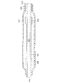
- FIG. 1 is a schematic view for explaining a catheter according to an embodiment of the present invention
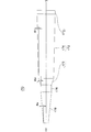
- FIG. 2 is a sectional view for explaining the vicinity of a guide wire opening of the catheter shown in FIG. 1
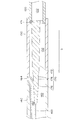
- FIG. 2 is a cross-sectional view for explaining the vicinity of a balloon of the catheter shown in FIG.
- the balloon catheter 100 is applied to the treatment of a site where surgical operation is difficult or the treatment for the purpose of minimally invasive to the human body, examination such as cardiac angiography, the hub 110, the proximal shaft. 120, an intermediate shaft 130, a tip shaft 140, a balloon 150, an inner tube shaft 160, and a reinforcing body 170, and is used to guide the guide wire 180 to a target site in the living body.
- PTCA percutaneous coronary artery angioplasty
- coronary balloon catheter 100 is the target site.
- PTCA percutaneous coronary artery angioplasty
- the guide wire 180 protruding from the tip of the balloon catheter 100 passes through the stenosis and widens the stenosis while guiding the tip of the subsequent balloon catheter 100.
- the hub 110 has an opening 112 formed with a luer taper for connecting an auxiliary device, and is joined to the proximal shaft 120 in a liquid-tight state.
- the auxiliary device is, for example, an inflator (pressure applying device) for supplying balloon expansion fluid.
- the balloon expansion fluid is water, physiological saline, electrolyte solution, or the like.
- the proximal shaft 120 is tubular, has a lumen 122 communicating with the opening 112 of the hub 110, and is joined to the inner tube shaft 160 in a liquid-tight state.
- the intermediate shaft 130 has a tubular shape, has a lumen 132 that communicates with the lumen 122 of the proximal shaft 120, and is joined to the distal shaft 140 in a liquid-tight state.
- the tip shaft 140 has a tubular shape, has a lumen 142 communicating with the lumen 132 of the intermediate shaft 130, and the balloon 150 is connected in a liquid-tight state.
- the balloon 150 is configured to be expandable and communicates with the lumen 142 of the tip shaft 140. Since the lumen 142 of the distal shaft 140 communicates with the opening 112 of the hub 110 via the lumen 132 of the intermediate shaft 130 and the lumen 122 of the proximal shaft 120, the lumen 142 is introduced from the opening 112 of the hub 110. Balloon expansion fluid can reach the interior of the balloon 150.
- the inner tube shaft 160 has a tubular shape and is introduced from the boundary between the tip shaft 140 and the intermediate shaft 130 in a state of being liquid-tight inside the tip shaft 140, and penetrates the lumen 142 and the balloon 150 of the tip shaft 140.
- the tip 161 protrudes from the balloon 150 in a liquid-tight state, and includes an opening (guide wire opening) 164 located at the boundary and an opening 166 located on the end surface of the tip 161. It has a lumen 162 in communication.
- the lumen 162 is used for inserting the guide wire 180.
- Reference numeral 168 indicates a coil-shaped contrast marker arranged around the inner tube shaft 160.
- the contrast marker 168 is used, for example, to facilitate positioning of the balloon 150 at a stenosis site under fluoroscopy.
- the reinforcing body 170 is substantially solid in a taper shape with respect to the axial direction S, and is disposed to suppress kinks, and has a proximal end portion 172, a distal end portion 178, and a transition portion 176.
- the proximal end portion 172 has a tapered shape, is fixed to the proximal shaft 120, and is disposed in the lumen 132 of the intermediate shaft 130.
- the tip 178 is tapered and is disposed within the lumen 142 of the tip shaft 140.
- the transition 176 is aligned with the guide wire opening 164.
- Reference numeral 171 denotes a fixed (joined) location.
- the reinforcing body 170 is substantially tapered and has a small influence on the flow path of the balloon expansion fluid (because resistance to the flow of the balloon expansion fluid is small), a decrease in the differential time performance, which is a contraction time after the balloon expansion, is suppressed.
- the reinforcing body 170 has the straight transition part 176, the physical property difference in the axial direction S is small, and the transition of the rigidity is smooth, so that it has good kink resistance.
- the straight transition portion 176 is aligned with the guide wire opening 164, for example, the vicinity of the guide wire opening 164 in a narrowed state is bent due to the presence of the inner tube shaft 160, and the guide wire opening 164 is bent.
- the constituent material of the hub 110 is, for example, a thermoplastic resin such as polycarbonate, polyamide, polysulfone, polyarylate, or methacrylate-butylene-styrene copolymer.
- the constituent material of the proximal shaft 120 is a metal material having a relatively large rigidity, for example, stainless steel, stainless extensible alloy, Ni—Ti alloy, brass, and aluminum. If necessary, it is also possible to apply a resin material having relatively large rigidity, for example, polyimide, vinyl chloride, or polycarbonate.
- the outer diameter of the base shaft 120 is about 0.3 to 3 mm, preferably 0.5 to 1.5 mm.
- the wall thickness of the proximal shaft 120 is about 10 to 150 ⁇ m, preferably 20 to 100 ⁇ m.
- the length of the proximal shaft 120 is 300 to 2000 mm, preferably 700 to 1500 mm.
- the constituent materials of the intermediate shaft 130 and the tip shaft 140 are, for example, a polymer material such as polyolefin, a cross-linked polyolefin, polyvinyl chloride, polyamide, polyamide elastomer, polyester, polyester elastomer, polyurethane, polyurethane elastomer, fluororesin, polyimide, or the like. It is a mixture of these.
- the polyolefin is, for example, polyethylene, polypropylene, polybutene, ethylene-propylene copolymer, ethylene-vinyl acetate copolymer, ionomer, or a mixture of two or more thereof.
- the outer diameters of the tip shaft 140 and the intermediate shaft 130 are 0.5 to 1.5 mm, more preferably 0.7 to 1.1 mm.
- the wall thickness of the tip shaft 140 and the intermediate shaft 130 is 25 to 200 ⁇ m, more preferably 50 to 100 ⁇ m.
- the lengths of the tip shaft 140 and the intermediate shaft 130 are 300 to 2000 mm, more preferably 300 to 1500 mm.
- the constituent material of the balloon 150 is preferably flexible, for example, polyolefin, cross-linked polyolefin, polyester, polyester elastomer, polyvinyl chloride, polyurethane, polyurethane elastomer, polyphenylene sulfide, polyamide, polyamide elastomer, fluororesin, etc. High polymer materials, silicone rubber, latex rubber.
- the polyester is, for example, polyethylene terephthalate.
- the constituent material of the balloon 150 is not limited to a form in which the polymer material is used alone, and for example, a film in which the polymer material is appropriately laminated can be applied.
- the outer diameter of the cylindrical portion of the balloon 150 is set to 1.0 to 10 mm, preferably 1.0 to 5.0 mm when expanded.
- the length of the balloon 150 alone is 5 to 50 mm, preferably 10 to 40 mm.
- the overall length of the balloon 150 is 10 to 70 mm, preferably 15 to 60 mm.
- the constituent material of the inner tube shaft 160 is preferably flexible.
- the outer diameter of the inner tube shaft 160 is about 0.1 to 1.0 mm, preferably 0.3 to 0.7 mm.
- the wall thickness of the inner tube shaft 160 is about 10 to 150 ⁇ m, preferably 20 to 100 ⁇ m.
- the length of the inner tube shaft 160 is 100 to 2000 mm, preferably 200 to 1500 mm.
- the constituent material of the reinforcing body 170 is preferably a metal material having good rigidity and workability, such as stainless steel, stainless extensible alloy, and Ni—Ti alloy.
- the contrast marker 168 is made of an X-ray opaque material from the viewpoint of obtaining a clear contrast image under X-ray fluoroscopy.
- the radiopaque material is, for example, platinum, gold, tungsten, iridium, or an alloy thereof.
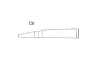
- FIG. 4 is a side view for explaining the shape of the reinforcing body shown in FIG.
- the outer diameter and inner diameter of the proximal shaft 120 are 0.64 mm and 0.46 mm, and the outer diameter, inner diameter and length of the intermediate shaft 130 are 0.85 mm, 0.67 mm and 150 mm.
- the outer diameter and inner diameter are 0.88 mm and 0.76 mm, the outer diameter of the inner tube shaft 160 is 0.56 mm, and the inner diameter of the inner tube shaft 160 (the inner diameter of the guide wire opening 164) is 0.41 mm. Assume the case.
- the base end portion 172 of the reinforcing body 170 includes a base portion 173, a first tapered portion 174, and a second tapered portion 175.
- the base portion 173 is a portion that is fixed (joined) to the proximal shaft 120, and has a straight shape for easy fixing.
- the length and outer diameter of the base 173 are 5.0 mm and 0.34 mm.
- the fixing method is not particularly limited, and for example, welding is applied.
- the first tapered portion 174 is located on the base portion 173 side (the proximal shaft 120 side), and the second tapered portion 175 is located on the transition portion 176 side (the distal shaft 140 side).
- the taper angle theta beta of the first tapered portion 174, the taper angle theta gamma of the second tapered portion 175 are different, the taper angle theta beta, larger taper angle theta gamma. That is, the taper angle of the tapered portions 174 and 175 of the base end portion 172 changes midway, thereby reducing the difference in physical properties in the axial direction S of the reinforcing body 170, smoothing the transition of rigidity, and preventing kink resistance. Improves sex.
- the length of the first tapered portion 174, the outer diameter of the boundary with the base portion 173, and the taper angle ⁇ ⁇ are 95.0 mm, 0.34 mm, and 0.02 degrees
- the outer diameter and taper angle ⁇ ⁇ at the boundary with the transition portion 176 are 10.0 mm, 0.28 mm, and 0.23 degrees.
- the length of the transition part 176 is larger than the inner diameter of the guide wire opening 164, and the center of the guide wire opening 164 is aligned with the center of the transition part 176 in the axial direction S. Thereby, it is possible to efficiently suppress the influence on the differential time performance when the relative position between the guide wire opening 164 (inner tube shaft 160) and the transition portion 176 varies.
- the length of the transition portion 176 is 10.0 mm, and in this case, a variation of up to ⁇ 5.0 mm is absorbed.
- the taper angle ⁇ ⁇ of the distal end portion 178 is larger than the taper angle ⁇ ⁇ of the first tapered portion 174 of the base end portion 172 and smaller than the taper angle ⁇ ⁇ of the second tapered portion 175.
- the physical property difference in the axial direction S of the reinforcing body 170 is reduced, the transition of rigidity is made smooth, and the kink resistance is improved.
- the length of the tip portion 178, the outer diameter of the tip end surface, the outer diameter of the boundary with the transition portion 176, and the taper angle ⁇ ⁇ are 45.0 mm, 0.10 mm, 0.20 mm, and 0.06 degrees.
- 5 and 6 are side views for explaining the first and second modifications.
- the reinforcing body 170 is not limited to a symmetric shape with respect to the axial direction S, and may be a distorted tapered shape.
- FIG. 7 is a cross-sectional view for explaining the third modification.
- the fixing of the base end part 172 (base part 173) of the reinforcing body 170 to the base end shaft 120 is not limited to a form in which a part located on the side opposite to the side where the guide wire opening 164 is located is applied.
- a portion on the side where the guide wire opening 164 is located can be used for fixing to the proximal shaft 120.
- the reinforcing body is substantially tapered and has a small influence on the flow path of the balloon expansion fluid (because resistance to the flow of the balloon expansion fluid is small). A decrease in the differential time performance, which is the contraction time, is suppressed.
- the reinforcing body since the reinforcing body has a straight transition portion, the difference in physical properties in the axial direction of the reinforcing body is small, and the transition of the rigidity is smooth, so that it has good kink resistance.
- the straight transition portion is aligned with the guide wire opening, for example, the guide wire opening (inner tube shaft) is bent near the guide wire opening in the narrowed state due to the presence of the inner tube shaft.
- the present invention is not limited to the above-described embodiment, and various modifications can be made within the scope of the claims.
- it can be applied to stent delivery.
- the hydrophilic polymer include a maleic anhydride such as a cellulose polymer such as hydroxypropyl cellulose, a polyethylene oxide polymer such as polyethylene glycol, and a maleic anhydride copolymer such as a methyl vinyl ether maleic anhydride copolymer.
- Acid polymer materials, acrylamide polymer materials such as dimethylacrylamide-glycidyl methacrylate copolymer, and water-soluble nylon.
- balloon catheter 110 hub, 112 opening, 120 proximal shaft, 122 lumens, 130 intermediate shaft, 132 lumens, 140 tip shaft, 142 lumens, 150 balloon, 160 inner tube shaft, 161 tip, 162 lumens, 164 guide wire opening, 166 opening, 168 contrast markers, 170 reinforcement, 171 fixing (joining) location, 172 proximal end, 173 base, 174 first tapered portion, 175 second tapered portion, 176 Transition Department, 178 tip, 180 guide wire, S axial direction of the reinforcement, ⁇ ⁇ , ⁇ ⁇ , ⁇ ⁇ taper angle.
Landscapes
- Health & Medical Sciences (AREA)
- Life Sciences & Earth Sciences (AREA)
- Heart & Thoracic Surgery (AREA)
- Anesthesiology (AREA)
- Biophysics (AREA)
- Pulmonology (AREA)
- Engineering & Computer Science (AREA)
- Biomedical Technology (AREA)
- Hematology (AREA)
- Animal Behavior & Ethology (AREA)
- General Health & Medical Sciences (AREA)
- Public Health (AREA)
- Veterinary Medicine (AREA)
- Child & Adolescent Psychology (AREA)
- Vascular Medicine (AREA)
- Media Introduction/Drainage Providing Device (AREA)
Priority Applications (5)
| Application Number | Priority Date | Filing Date | Title |
|---|---|---|---|
| JP2014505969A JP6031087B2 (ja) | 2012-03-23 | 2012-11-28 | バルーンカテーテル |
| ES12871924.2T ES2668681T3 (es) | 2012-03-23 | 2012-11-28 | Catéter de balón |
| CN201280069976.3A CN104114223B (zh) | 2012-03-23 | 2012-11-28 | 球囊导管 |
| EP12871924.2A EP2829299B1 (en) | 2012-03-23 | 2012-11-28 | Balloon catheter |
| US14/488,981 US9364645B2 (en) | 2012-03-23 | 2014-09-17 | Balloon catheter |
Applications Claiming Priority (2)
| Application Number | Priority Date | Filing Date | Title |
|---|---|---|---|
| JP2012068126 | 2012-03-23 | ||
| JP2012-068126 | 2012-03-23 |
Related Child Applications (1)
| Application Number | Title | Priority Date | Filing Date |
|---|---|---|---|
| US14/488,981 Continuation US9364645B2 (en) | 2012-03-23 | 2014-09-17 | Balloon catheter |
Publications (1)
| Publication Number | Publication Date |
|---|---|
| WO2013140669A1 true WO2013140669A1 (ja) | 2013-09-26 |
Family
ID=49222157
Family Applications (1)
| Application Number | Title | Priority Date | Filing Date |
|---|---|---|---|
| PCT/JP2012/080750 WO2013140669A1 (ja) | 2012-03-23 | 2012-11-28 | バルーンカテーテル |
Country Status (6)
| Country | Link |
|---|---|
| US (1) | US9364645B2 (zh) |
| EP (1) | EP2829299B1 (zh) |
| JP (1) | JP6031087B2 (zh) |
| CN (1) | CN104114223B (zh) |
| ES (1) | ES2668681T3 (zh) |
| WO (1) | WO2013140669A1 (zh) |
Cited By (3)
| Publication number | Priority date | Publication date | Assignee | Title |
|---|---|---|---|---|
| JP5631475B1 (ja) * | 2013-11-14 | 2014-11-26 | 日本ライフライン株式会社 | バルーンカテーテル |
| CN104857618A (zh) * | 2014-02-24 | 2015-08-26 | 朝日英达科株式会社 | 导管 |
| WO2016114207A1 (ja) * | 2015-01-14 | 2016-07-21 | テルモ株式会社 | カテーテル |
Families Citing this family (3)
| Publication number | Priority date | Publication date | Assignee | Title |
|---|---|---|---|---|
| WO2016143556A1 (ja) * | 2015-03-06 | 2016-09-15 | 日本ゼオン株式会社 | 内視鏡用処置具 |
| WO2019173313A1 (en) * | 2018-03-06 | 2019-09-12 | Medtronic Vascular, Inc. | Rapid exchange balloon catheter |
| WO2021186664A1 (ja) * | 2020-03-19 | 2021-09-23 | 朝日インテック株式会社 | カテーテル |
Citations (4)
| Publication number | Priority date | Publication date | Assignee | Title |
|---|---|---|---|---|
| JP2001095924A (ja) | 1999-09-28 | 2001-04-10 | Terumo Corp | カテーテル |
| JP2001333984A (ja) * | 2000-05-30 | 2001-12-04 | Kawasumi Lab Inc | バルーンカテーテル |
| JP2002126085A (ja) * | 2000-10-27 | 2002-05-08 | Kawasumi Lab Inc | バルーンカテーテル |
| JP2003517901A (ja) * | 1999-12-21 | 2003-06-03 | アドヴァンスト カーディオヴァスキュラー システムズ インコーポレーテッド | 支持マンドレルを備えた高速交換カテーテル |
Family Cites Families (4)
| Publication number | Priority date | Publication date | Assignee | Title |
|---|---|---|---|---|
| US6066114A (en) * | 1998-09-09 | 2000-05-23 | Schneider (Usa) Inc | Stiffening member in a rapid exchange dilation catheter |
| US7367967B2 (en) * | 2003-09-17 | 2008-05-06 | Boston Scientific Scimed, Inc. | Catheter with sheathed hypotube |
| WO2010102105A1 (en) * | 2009-03-06 | 2010-09-10 | Cook Incorporated | Reinforced rapid exchange catheter |
| CN103796707B (zh) * | 2011-05-26 | 2016-11-09 | 雅培心血管系统有限公司 | 具有阶梯形切薄的海波管的导管 |
-
2012
- 2012-11-28 EP EP12871924.2A patent/EP2829299B1/en active Active
- 2012-11-28 JP JP2014505969A patent/JP6031087B2/ja active Active
- 2012-11-28 WO PCT/JP2012/080750 patent/WO2013140669A1/ja active Application Filing
- 2012-11-28 CN CN201280069976.3A patent/CN104114223B/zh active Active
- 2012-11-28 ES ES12871924.2T patent/ES2668681T3/es active Active
-
2014
- 2014-09-17 US US14/488,981 patent/US9364645B2/en active Active
Patent Citations (4)
| Publication number | Priority date | Publication date | Assignee | Title |
|---|---|---|---|---|
| JP2001095924A (ja) | 1999-09-28 | 2001-04-10 | Terumo Corp | カテーテル |
| JP2003517901A (ja) * | 1999-12-21 | 2003-06-03 | アドヴァンスト カーディオヴァスキュラー システムズ インコーポレーテッド | 支持マンドレルを備えた高速交換カテーテル |
| JP2001333984A (ja) * | 2000-05-30 | 2001-12-04 | Kawasumi Lab Inc | バルーンカテーテル |
| JP2002126085A (ja) * | 2000-10-27 | 2002-05-08 | Kawasumi Lab Inc | バルーンカテーテル |
Cited By (11)
| Publication number | Priority date | Publication date | Assignee | Title |
|---|---|---|---|---|
| JP5631475B1 (ja) * | 2013-11-14 | 2014-11-26 | 日本ライフライン株式会社 | バルーンカテーテル |
| JP2015093173A (ja) * | 2013-11-14 | 2015-05-18 | 日本ライフライン株式会社 | バルーンカテーテル |
| WO2015072300A1 (ja) * | 2013-11-14 | 2015-05-21 | 日本ライフライン株式会社 | バルーンカテーテル |
| CN105473177A (zh) * | 2013-11-14 | 2016-04-06 | 日本来富恩株式会社 | 球囊导管 |
| KR101788491B1 (ko) | 2013-11-14 | 2017-10-19 | 니혼라이프라인 가부시키가이샤 | 벌룬 카테터 |
| CN104857618A (zh) * | 2014-02-24 | 2015-08-26 | 朝日英达科株式会社 | 导管 |
| JP2015156956A (ja) * | 2014-02-24 | 2015-09-03 | 朝日インテック株式会社 | カテーテル |
| CN104857618B (zh) * | 2014-02-24 | 2018-07-17 | 朝日英达科株式会社 | 导管 |
| WO2016114207A1 (ja) * | 2015-01-14 | 2016-07-21 | テルモ株式会社 | カテーテル |
| JPWO2016114207A1 (ja) * | 2015-01-14 | 2017-10-19 | テルモ株式会社 | カテーテル |
| US10493236B2 (en) | 2015-01-14 | 2019-12-03 | Terumo Kabushiki Kaisha | Catheter |
Also Published As
| Publication number | Publication date |
|---|---|
| EP2829299A4 (en) | 2015-11-11 |
| US20150005803A1 (en) | 2015-01-01 |
| EP2829299A1 (en) | 2015-01-28 |
| CN104114223A (zh) | 2014-10-22 |
| JPWO2013140669A1 (ja) | 2015-08-03 |
| EP2829299B1 (en) | 2018-04-18 |
| ES2668681T3 (es) | 2018-05-21 |
| CN104114223B (zh) | 2017-02-22 |
| US9364645B2 (en) | 2016-06-14 |
| JP6031087B2 (ja) | 2016-11-24 |
Similar Documents
| Publication | Publication Date | Title |
|---|---|---|
| US5569200A (en) | Vascular catheter | |
| JP3915862B2 (ja) | カテーテル | |
| EP3043858B1 (en) | Low-profile occlusion catheter | |
| JP6031087B2 (ja) | バルーンカテーテル | |
| US10751514B2 (en) | Guide extension catheter | |
| JP5769992B2 (ja) | カテーテル | |
| JP4544526B2 (ja) | カテーテル | |
| JP2015525638A (ja) | ガイド延長カテーテル | |
| CN110575606A (zh) | 一种药物洗脱球囊扩张导管及使用方法 | |
| JP2013223663A (ja) | バルーンカテーテル用保護スリーブ、バルーンカテーテルシステムおよびステントデリバリーシステム | |
| JP5826592B2 (ja) | 拡張カテーテル | |
| US20150320985A1 (en) | Balloon catheter | |
| JP5947716B2 (ja) | ステントデリバリーシステムの製造方法 | |
| JP2010525880A (ja) | バルーンカテーテル | |
| JP2002355313A (ja) | カテーテルチューブおよびバルーンカテーテル | |
| JP2000217923A (ja) | バルーンカテーテルおよびその製造方法 | |
| JP6363922B2 (ja) | カテーテル | |
| JP2012096121A (ja) | バルーンカテーテル | |
| JP7555487B2 (ja) | カテーテル | |
| JP2011200588A (ja) | バルーンカテーテル及びその製造方法 | |
| JP2018161415A (ja) | 医療用長尺体 | |
| JP2011056148A (ja) | バルーンカテーテル | |
| JP2002291898A (ja) | バルーンカテーテルおよびその製造方法 | |
| JP6475528B2 (ja) | バルーンカテーテル | |
| JP5422375B2 (ja) | バルーンカテーテル |
Legal Events
| Date | Code | Title | Description |
|---|---|---|---|
| 121 | Ep: the epo has been informed by wipo that ep was designated in this application |
Ref document number: 12871924 Country of ref document: EP Kind code of ref document: A1 |
|
| ENP | Entry into the national phase |
Ref document number: 2014505969 Country of ref document: JP Kind code of ref document: A |
|
| WWE | Wipo information: entry into national phase |
Ref document number: 2012871924 Country of ref document: EP |
|
| NENP | Non-entry into the national phase |
Ref country code: DE |