WO2013140669A1 - バルーンカテーテル - Google Patents
バルーンカテーテル Download PDFInfo
- Publication number
- WO2013140669A1 WO2013140669A1 PCT/JP2012/080750 JP2012080750W WO2013140669A1 WO 2013140669 A1 WO2013140669 A1 WO 2013140669A1 JP 2012080750 W JP2012080750 W JP 2012080750W WO 2013140669 A1 WO2013140669 A1 WO 2013140669A1
- Authority
- WO
- WIPO (PCT)
- Prior art keywords
- shaft
- proximal
- guide wire
- reinforcing body
- balloon catheter
- Prior art date
Links
Images


Classifications
-
- A—HUMAN NECESSITIES
- A61—MEDICAL OR VETERINARY SCIENCE; HYGIENE
- A61M—DEVICES FOR INTRODUCING MEDIA INTO, OR ONTO, THE BODY; DEVICES FOR TRANSDUCING BODY MEDIA OR FOR TAKING MEDIA FROM THE BODY; DEVICES FOR PRODUCING OR ENDING SLEEP OR STUPOR
- A61M25/00—Catheters; Hollow probes
- A61M25/10—Balloon catheters
- A61M25/104—Balloon catheters used for angioplasty
-
- A—HUMAN NECESSITIES
- A61—MEDICAL OR VETERINARY SCIENCE; HYGIENE
- A61M—DEVICES FOR INTRODUCING MEDIA INTO, OR ONTO, THE BODY; DEVICES FOR TRANSDUCING BODY MEDIA OR FOR TAKING MEDIA FROM THE BODY; DEVICES FOR PRODUCING OR ENDING SLEEP OR STUPOR
- A61M25/00—Catheters; Hollow probes
- A61M25/0043—Catheters; Hollow probes characterised by structural features
- A61M25/005—Catheters; Hollow probes characterised by structural features with embedded materials for reinforcement, e.g. wires, coils, braids
- A61M25/0052—Localized reinforcement, e.g. where only a specific part of the catheter is reinforced, for rapid exchange guidewire port
-
- A—HUMAN NECESSITIES
- A61—MEDICAL OR VETERINARY SCIENCE; HYGIENE
- A61M—DEVICES FOR INTRODUCING MEDIA INTO, OR ONTO, THE BODY; DEVICES FOR TRANSDUCING BODY MEDIA OR FOR TAKING MEDIA FROM THE BODY; DEVICES FOR PRODUCING OR ENDING SLEEP OR STUPOR
- A61M25/00—Catheters; Hollow probes
- A61M25/0043—Catheters; Hollow probes characterised by structural features
- A61M2025/0059—Catheters; Hollow probes characterised by structural features having means for preventing the catheter, sheath or lumens from collapsing due to outer forces, e.g. compressing forces, or caused by twisting or kinking
-
- A—HUMAN NECESSITIES
- A61—MEDICAL OR VETERINARY SCIENCE; HYGIENE
- A61M—DEVICES FOR INTRODUCING MEDIA INTO, OR ONTO, THE BODY; DEVICES FOR TRANSDUCING BODY MEDIA OR FOR TAKING MEDIA FROM THE BODY; DEVICES FOR PRODUCING OR ENDING SLEEP OR STUPOR
- A61M25/00—Catheters; Hollow probes
- A61M25/01—Introducing, guiding, advancing, emplacing or holding catheters
- A61M2025/0183—Rapid exchange or monorail catheters
-
- A—HUMAN NECESSITIES
- A61—MEDICAL OR VETERINARY SCIENCE; HYGIENE
- A61M—DEVICES FOR INTRODUCING MEDIA INTO, OR ONTO, THE BODY; DEVICES FOR TRANSDUCING BODY MEDIA OR FOR TAKING MEDIA FROM THE BODY; DEVICES FOR PRODUCING OR ENDING SLEEP OR STUPOR
- A61M25/00—Catheters; Hollow probes
- A61M25/10—Balloon catheters
- A61M2025/1043—Balloon catheters with special features or adapted for special applications
- A61M2025/109—Balloon catheters with special features or adapted for special applications having balloons for removing solid matters, e.g. by grasping or scraping plaque, thrombus or other matters that obstruct the flow
Definitions
- the present invention relates to a balloon catheter.
- the rapid exchange type balloon catheter has a proximal shaft, an intermediate shaft, and a distal shaft, and the guide wire opening is located at the boundary between the intermediate shaft and the distal shaft. For example, the bending of the guide wire is concentrated near the guide wire opening. Since there is a possibility that kinking may occur, a reinforcing body is disposed (see, for example, Patent Document 1).
- the reinforcement body is straight and is disposed in the lumen for introducing and discharging the balloon expansion fluid.
- the diameter of the reinforcement body is increased to increase the rigidity, the flow path of the balloon expansion fluid is narrowed. Therefore, the introduction and discharge of the expansion fluid are adversely affected, and in particular, there is a problem that the differential time performance that is the contraction time after the balloon expansion is lowered.
- the present invention has been made in order to solve the problems associated with the above-described conventional technology, and an object thereof is to provide a balloon catheter capable of achieving both kink resistance and differential time performance.
- the present invention provides a proximal shaft, a distal shaft, an intermediate shaft positioned between the proximal shaft and the distal shaft, the proximal shaft, the intermediate shaft, and the distal shaft.
- a reinforcement body that is disposed in the body and suppresses kinks.
- the reinforcing body is fixed to the proximal shaft, and has a tapered proximal end portion disposed in the lumen located on the intermediate shaft, and a tapered proximal end portion disposed in the lumen located on the distal shaft. And a straight transition portion located between the proximal end portion and the distal end portion, and the transition portion is aligned with the guide wire opening.
- the reinforcing body is substantially tapered and has a small influence on the flow path of the balloon expansion fluid (because resistance to the flow of the balloon expansion fluid is small). Is suppressed.
- the reinforcing body has a straight transition portion, the difference in physical properties in the axial direction is small, and the transition of the rigidity is smooth, so that it has good kink resistance.
- the straight transition portion is aligned with the guide wire opening, for example, the guide wire opening (inner tube shaft) is bent near the guide wire opening in the narrowed state due to the presence of the inner tube shaft.
- the taper angle that is the inclination angle of the outer peripheral surface with respect to the axial direction of the reinforcing body at the base end portion Is preferably changed in the middle.
- part located in the front end shaft side in a base end part is larger than the taper angle of the site
- the taper angle of the distal end portion is preferably larger than the taper angle of the portion located on the proximal shaft side in the proximal end portion and smaller than the taper angle of the portion located on the distal shaft side in the proximal end portion.
- the center of the guide wire opening is related to the axial direction of the reinforcing body. It is preferably aligned with the center of the transition. Moreover, it is preferable that the length of the transition part regarding the axial direction of a reinforcement body is larger than the internal diameter of a guide wire opening part.
- the portion fixed to the base end shaft in the base end portion is straight.
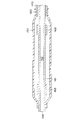
- FIG. 1 is a schematic view for explaining a catheter according to an embodiment of the present invention
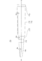
- FIG. 2 is a sectional view for explaining the vicinity of a guide wire opening of the catheter shown in FIG. 1
- FIG. 2 is a cross-sectional view for explaining the vicinity of a balloon of the catheter shown in FIG.
- the balloon catheter 100 is applied to the treatment of a site where surgical operation is difficult or the treatment for the purpose of minimally invasive to the human body, examination such as cardiac angiography, the hub 110, the proximal shaft. 120, an intermediate shaft 130, a tip shaft 140, a balloon 150, an inner tube shaft 160, and a reinforcing body 170, and is used to guide the guide wire 180 to a target site in the living body.
- PTCA percutaneous coronary artery angioplasty
- coronary balloon catheter 100 is the target site.
- PTCA percutaneous coronary artery angioplasty
- the guide wire 180 protruding from the tip of the balloon catheter 100 passes through the stenosis and widens the stenosis while guiding the tip of the subsequent balloon catheter 100.
- the hub 110 has an opening 112 formed with a luer taper for connecting an auxiliary device, and is joined to the proximal shaft 120 in a liquid-tight state.
- the auxiliary device is, for example, an inflator (pressure applying device) for supplying balloon expansion fluid.
- the balloon expansion fluid is water, physiological saline, electrolyte solution, or the like.
- the proximal shaft 120 is tubular, has a lumen 122 communicating with the opening 112 of the hub 110, and is joined to the inner tube shaft 160 in a liquid-tight state.
- the intermediate shaft 130 has a tubular shape, has a lumen 132 that communicates with the lumen 122 of the proximal shaft 120, and is joined to the distal shaft 140 in a liquid-tight state.
- the tip shaft 140 has a tubular shape, has a lumen 142 communicating with the lumen 132 of the intermediate shaft 130, and the balloon 150 is connected in a liquid-tight state.
- the balloon 150 is configured to be expandable and communicates with the lumen 142 of the tip shaft 140. Since the lumen 142 of the distal shaft 140 communicates with the opening 112 of the hub 110 via the lumen 132 of the intermediate shaft 130 and the lumen 122 of the proximal shaft 120, the lumen 142 is introduced from the opening 112 of the hub 110. Balloon expansion fluid can reach the interior of the balloon 150.
- the inner tube shaft 160 has a tubular shape and is introduced from the boundary between the tip shaft 140 and the intermediate shaft 130 in a state of being liquid-tight inside the tip shaft 140, and penetrates the lumen 142 and the balloon 150 of the tip shaft 140.
- the tip 161 protrudes from the balloon 150 in a liquid-tight state, and includes an opening (guide wire opening) 164 located at the boundary and an opening 166 located on the end surface of the tip 161. It has a lumen 162 in communication.
- the lumen 162 is used for inserting the guide wire 180.
- Reference numeral 168 indicates a coil-shaped contrast marker arranged around the inner tube shaft 160.
- the contrast marker 168 is used, for example, to facilitate positioning of the balloon 150 at a stenosis site under fluoroscopy.
- the reinforcing body 170 is substantially solid in a taper shape with respect to the axial direction S, and is disposed to suppress kinks, and has a proximal end portion 172, a distal end portion 178, and a transition portion 176.
- the proximal end portion 172 has a tapered shape, is fixed to the proximal shaft 120, and is disposed in the lumen 132 of the intermediate shaft 130.
- the tip 178 is tapered and is disposed within the lumen 142 of the tip shaft 140.
- the transition 176 is aligned with the guide wire opening 164.
- Reference numeral 171 denotes a fixed (joined) location.
- the reinforcing body 170 is substantially tapered and has a small influence on the flow path of the balloon expansion fluid (because resistance to the flow of the balloon expansion fluid is small), a decrease in the differential time performance, which is a contraction time after the balloon expansion, is suppressed.
- the reinforcing body 170 has the straight transition part 176, the physical property difference in the axial direction S is small, and the transition of the rigidity is smooth, so that it has good kink resistance.
- the straight transition portion 176 is aligned with the guide wire opening 164, for example, the vicinity of the guide wire opening 164 in a narrowed state is bent due to the presence of the inner tube shaft 160, and the guide wire opening 164 is bent.
- the constituent material of the hub 110 is, for example, a thermoplastic resin such as polycarbonate, polyamide, polysulfone, polyarylate, or methacrylate-butylene-styrene copolymer.
- the constituent material of the proximal shaft 120 is a metal material having a relatively large rigidity, for example, stainless steel, stainless extensible alloy, Ni—Ti alloy, brass, and aluminum. If necessary, it is also possible to apply a resin material having relatively large rigidity, for example, polyimide, vinyl chloride, or polycarbonate.
- the outer diameter of the base shaft 120 is about 0.3 to 3 mm, preferably 0.5 to 1.5 mm.
- the wall thickness of the proximal shaft 120 is about 10 to 150 ⁇ m, preferably 20 to 100 ⁇ m.
- the length of the proximal shaft 120 is 300 to 2000 mm, preferably 700 to 1500 mm.
- the constituent materials of the intermediate shaft 130 and the tip shaft 140 are, for example, a polymer material such as polyolefin, a cross-linked polyolefin, polyvinyl chloride, polyamide, polyamide elastomer, polyester, polyester elastomer, polyurethane, polyurethane elastomer, fluororesin, polyimide, or the like. It is a mixture of these.
- the polyolefin is, for example, polyethylene, polypropylene, polybutene, ethylene-propylene copolymer, ethylene-vinyl acetate copolymer, ionomer, or a mixture of two or more thereof.
- the outer diameters of the tip shaft 140 and the intermediate shaft 130 are 0.5 to 1.5 mm, more preferably 0.7 to 1.1 mm.
- the wall thickness of the tip shaft 140 and the intermediate shaft 130 is 25 to 200 ⁇ m, more preferably 50 to 100 ⁇ m.
- the lengths of the tip shaft 140 and the intermediate shaft 130 are 300 to 2000 mm, more preferably 300 to 1500 mm.
- the constituent material of the balloon 150 is preferably flexible, for example, polyolefin, cross-linked polyolefin, polyester, polyester elastomer, polyvinyl chloride, polyurethane, polyurethane elastomer, polyphenylene sulfide, polyamide, polyamide elastomer, fluororesin, etc. High polymer materials, silicone rubber, latex rubber.
- the polyester is, for example, polyethylene terephthalate.
- the constituent material of the balloon 150 is not limited to a form in which the polymer material is used alone, and for example, a film in which the polymer material is appropriately laminated can be applied.
- the outer diameter of the cylindrical portion of the balloon 150 is set to 1.0 to 10 mm, preferably 1.0 to 5.0 mm when expanded.
- the length of the balloon 150 alone is 5 to 50 mm, preferably 10 to 40 mm.
- the overall length of the balloon 150 is 10 to 70 mm, preferably 15 to 60 mm.
- the constituent material of the inner tube shaft 160 is preferably flexible.
- the outer diameter of the inner tube shaft 160 is about 0.1 to 1.0 mm, preferably 0.3 to 0.7 mm.
- the wall thickness of the inner tube shaft 160 is about 10 to 150 ⁇ m, preferably 20 to 100 ⁇ m.
- the length of the inner tube shaft 160 is 100 to 2000 mm, preferably 200 to 1500 mm.
- the constituent material of the reinforcing body 170 is preferably a metal material having good rigidity and workability, such as stainless steel, stainless extensible alloy, and Ni—Ti alloy.
- the contrast marker 168 is made of an X-ray opaque material from the viewpoint of obtaining a clear contrast image under X-ray fluoroscopy.
- the radiopaque material is, for example, platinum, gold, tungsten, iridium, or an alloy thereof.
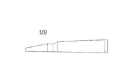
- FIG. 4 is a side view for explaining the shape of the reinforcing body shown in FIG.
- the outer diameter and inner diameter of the proximal shaft 120 are 0.64 mm and 0.46 mm, and the outer diameter, inner diameter and length of the intermediate shaft 130 are 0.85 mm, 0.67 mm and 150 mm.
- the outer diameter and inner diameter are 0.88 mm and 0.76 mm, the outer diameter of the inner tube shaft 160 is 0.56 mm, and the inner diameter of the inner tube shaft 160 (the inner diameter of the guide wire opening 164) is 0.41 mm. Assume the case.
- the base end portion 172 of the reinforcing body 170 includes a base portion 173, a first tapered portion 174, and a second tapered portion 175.
- the base portion 173 is a portion that is fixed (joined) to the proximal shaft 120, and has a straight shape for easy fixing.
- the length and outer diameter of the base 173 are 5.0 mm and 0.34 mm.
- the fixing method is not particularly limited, and for example, welding is applied.
- the first tapered portion 174 is located on the base portion 173 side (the proximal shaft 120 side), and the second tapered portion 175 is located on the transition portion 176 side (the distal shaft 140 side).
- the taper angle theta beta of the first tapered portion 174, the taper angle theta gamma of the second tapered portion 175 are different, the taper angle theta beta, larger taper angle theta gamma. That is, the taper angle of the tapered portions 174 and 175 of the base end portion 172 changes midway, thereby reducing the difference in physical properties in the axial direction S of the reinforcing body 170, smoothing the transition of rigidity, and preventing kink resistance. Improves sex.
- the length of the first tapered portion 174, the outer diameter of the boundary with the base portion 173, and the taper angle ⁇ ⁇ are 95.0 mm, 0.34 mm, and 0.02 degrees
- the outer diameter and taper angle ⁇ ⁇ at the boundary with the transition portion 176 are 10.0 mm, 0.28 mm, and 0.23 degrees.
- the length of the transition part 176 is larger than the inner diameter of the guide wire opening 164, and the center of the guide wire opening 164 is aligned with the center of the transition part 176 in the axial direction S. Thereby, it is possible to efficiently suppress the influence on the differential time performance when the relative position between the guide wire opening 164 (inner tube shaft 160) and the transition portion 176 varies.
- the length of the transition portion 176 is 10.0 mm, and in this case, a variation of up to ⁇ 5.0 mm is absorbed.
- the taper angle ⁇ ⁇ of the distal end portion 178 is larger than the taper angle ⁇ ⁇ of the first tapered portion 174 of the base end portion 172 and smaller than the taper angle ⁇ ⁇ of the second tapered portion 175.
- the physical property difference in the axial direction S of the reinforcing body 170 is reduced, the transition of rigidity is made smooth, and the kink resistance is improved.
- the length of the tip portion 178, the outer diameter of the tip end surface, the outer diameter of the boundary with the transition portion 176, and the taper angle ⁇ ⁇ are 45.0 mm, 0.10 mm, 0.20 mm, and 0.06 degrees.
- 5 and 6 are side views for explaining the first and second modifications.
- the reinforcing body 170 is not limited to a symmetric shape with respect to the axial direction S, and may be a distorted tapered shape.
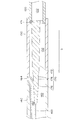
- FIG. 7 is a cross-sectional view for explaining the third modification.
- the fixing of the base end part 172 (base part 173) of the reinforcing body 170 to the base end shaft 120 is not limited to a form in which a part located on the side opposite to the side where the guide wire opening 164 is located is applied.
- a portion on the side where the guide wire opening 164 is located can be used for fixing to the proximal shaft 120.
- the reinforcing body is substantially tapered and has a small influence on the flow path of the balloon expansion fluid (because resistance to the flow of the balloon expansion fluid is small). A decrease in the differential time performance, which is the contraction time, is suppressed.
- the reinforcing body since the reinforcing body has a straight transition portion, the difference in physical properties in the axial direction of the reinforcing body is small, and the transition of the rigidity is smooth, so that it has good kink resistance.
- the straight transition portion is aligned with the guide wire opening, for example, the guide wire opening (inner tube shaft) is bent near the guide wire opening in the narrowed state due to the presence of the inner tube shaft.
- the present invention is not limited to the above-described embodiment, and various modifications can be made within the scope of the claims.
- it can be applied to stent delivery.
- the hydrophilic polymer include a maleic anhydride such as a cellulose polymer such as hydroxypropyl cellulose, a polyethylene oxide polymer such as polyethylene glycol, and a maleic anhydride copolymer such as a methyl vinyl ether maleic anhydride copolymer.
- Acid polymer materials, acrylamide polymer materials such as dimethylacrylamide-glycidyl methacrylate copolymer, and water-soluble nylon.
- balloon catheter 110 hub, 112 opening, 120 proximal shaft, 122 lumens, 130 intermediate shaft, 132 lumens, 140 tip shaft, 142 lumens, 150 balloon, 160 inner tube shaft, 161 tip, 162 lumens, 164 guide wire opening, 166 opening, 168 contrast markers, 170 reinforcement, 171 fixing (joining) location, 172 proximal end, 173 base, 174 first tapered portion, 175 second tapered portion, 176 Transition Department, 178 tip, 180 guide wire, S axial direction of the reinforcement, ⁇ ⁇ , ⁇ ⁇ , ⁇ ⁇ taper angle.
Landscapes
- Health & Medical Sciences (AREA)
- Life Sciences & Earth Sciences (AREA)
- Heart & Thoracic Surgery (AREA)
- Hematology (AREA)
- Engineering & Computer Science (AREA)
- Anesthesiology (AREA)
- Biomedical Technology (AREA)
- Pulmonology (AREA)
- Biophysics (AREA)
- Animal Behavior & Ethology (AREA)
- General Health & Medical Sciences (AREA)
- Public Health (AREA)
- Veterinary Medicine (AREA)
- Vascular Medicine (AREA)
- Child & Adolescent Psychology (AREA)
- Media Introduction/Drainage Providing Device (AREA)
Abstract
【課題】耐キンク性とデフタイム性能とを両立させ得るバルーンカテーテルを提供する。 【解決手段】基端シャフト120と、先端シャフト140と、基端シャフトと先端シャフトとの間に位置する中間シャフト130と、基端シャフト、中間シャフトおよび先端シャフトを貫通し、バルーンの拡張流体を導入および排出するルーメン122,132,142と、中間シャフトと先端シャフトとの境界に配置されるガイドワイヤー開口部164を有し、ルーメンを延長する内管シャフト160と、ルーメンに配置されてキンクを抑制する補強体170と、を有する。補強体170は、基端シャフトに固定され、中間シャフトに位置するルーメン内に配置されるテーパー状の基端部172と、先端シャフトに位置するルーメン内に配置されるテーパー状の先端部178と、基端部172と先端部178との間に位置するストレート状の移行部176と、を有する。移行部176は、ガイドワイヤー開口部164に位置合わせされている。
Description
本発明は、バルーンカテーテルに関する。
ラピッドエクスチェンジタイプのバルーンカテーテルは、基端シャフト、中間シャフトおよび先端シャフトを有し、ガイドワイヤー開口部は、中間シャフトと先端シャフトとの境界に位置し、例えば、ガイドワイヤー開口部近傍において曲がりの集中によりキンクが生じる虞があるため、補強体が配置されている(例えば、特許文献1参照。)。
しかし、補強体は、ストレート状であり、バルーン拡張流体を導入および排出するためのルーメンに配置されており、補強体の径を拡大して剛性を増加させる場合、バルーン拡張流体の流路が狭まるため、拡張流体の導入および排出に悪影響を与え、特に、バルーン拡張後の収縮時間であるデフタイム性能が低下する問題を有する。
一方、補強体をテーパー形状として、デフタイム性能に対する影響を抑制する場合、補強体の軸方向における物性差が大きくなり、耐キンク性が低下する問題を有する。
本発明は、上記従来技術に伴う課題を解決するためになされたものであり、耐キンク性とデフタイム性能とを両立させ得るバルーンカテーテルを提供することを目的とする。
上記目的を達成するための本発明は、基端シャフトと、先端シャフトと、前記基端シャフトと前記先端シャフトとの間に位置する中間シャフトと、前記基端シャフト、前記中間シャフトおよび前記先端シャフトを貫通し、バルーンの拡張流体を導入および排出するルーメンと、前記中間シャフトと前記先端シャフトとの境界に配置されるガイドワイヤー開口部を有し、前記ルーメンを延長する内管シャフトと、前記ルーメンに配置されてキンクを抑制する補強体と、を有するバルーンカテーテルである。前記補強体は、前記基端シャフトに固定され、前記中間シャフトに位置する前記ルーメン内に配置されるテーパー状の基端部と、前記先端シャフトに位置する前記ルーメン内に配置されるテーパー状の先端部と、前記基端部と前記先端部との間に位置するストレート状の移行部と、を有し、前記移行部は、前記ガイドワイヤー開口部に位置合わせされている。
本発明によれば、補強体は、略テーパー状であり、バルーン拡張流体の流路に対する影響が小さいため(バルーン拡張流体の流通に対する抵抗が小さいため)、バルーン拡張後の収縮時間であるデフタイム性能の低下が抑制される。また、補強体は、ストレート状の移行部を有するため、軸方向における物性差が小さく、剛性の移行がスムーズであるため、良好な耐キンク性を有する。さらに、ストレート状の移行部がガイドワイヤー開口部に位置合わせされているため、例えば、内管シャフトの存在により狭窄状態にあるガイドワイヤー開口部近傍が屈曲してガイドワイヤー開口部(内管シャフト)と移行部との相対位置が変動したとしても、ルーメン断面における移行部が占める部分は変化しないため、デフタイム性能に対する影響は小さく、安定したデフタイム性能を確保すること可能である。したがって、耐キンク性とデフタイム性能とを両立させ得るバルーンカテーテルを提供することができる。
なお、補強体の軸方向における物性差を小さくし、剛性の移行をスムーズとし、耐キンク性を向上させるには、基端部において、補強体の軸方向に対する外周面の傾斜角であるテーパー角が途中で変化していることが好ましい。また、基端部における先端シャフト側に位置する部位のテーパー角は、基端部における基端シャフト側に位置する部位のテーパー角より大きいことが好ましい。さらに、先端部のテーパー角は、基端部における基端シャフト側に位置する部位のテーパー角より大きく、かつ、基端部における先端シャフト側に位置する部位のテーパー角より小さいことが好ましい。
ガイドワイヤー開口部(内管シャフト)と移行部との相対位置が変動した際のデフタイム性能に対する影響を、効率的に抑制するためには、ガイドワイヤー開口部の中心が、補強体の軸方向に関する移行部の中央に位置合わせされていることが好ましい。また、補強体の軸方向に関する移行部の長さは、ガイドワイヤー開口部の内径より大きいことが好ましい。
基端シャフトに対する補強体の基端部の固定を容易とするためには、基端部における基端シャフトに固定される部位が、ストレート状であることが好ましい。
本発明のさらに他の目的、特徴および特質は、以後の説明および添付図面に例示される好ましい実施の形態を参照することによって、明らかになるであろう。
以下、本発明の実施の形態を、図面を参照しつつ説明する。
図1は、本発明の実施の形態に係るカテーテルを説明するための概略図、図2は、図1に示されるカテーテルのガイドワイヤー開口部近傍を説明するための断面図、図3は、図1に示されるカテーテルのバルーン近傍を説明するための断面図である。
本発明の実施の形態に係るバルーンカテーテル100は、外科的手術が困難な部位の治療または人体への低侵襲を目的とした治療、心臓血管造影などの検査に適用され、ハブ110、基端シャフト120、中間シャフト130、先端シャフト140、バルーン150、内管シャフト160および補強体170を有しており、ガイドワイヤー180を生体内の目的部位まで誘導するために用いられる。
外科的手術が困難な部位の治療は、例えば、心筋梗塞または狭心症に用いられる経皮的冠状動脈血管形成術(PTCA:Percutaneous Transluminal Coronary Angioplasty)であり、バルーンカテーテル100が目的部位である冠状動脈の狭窄部付近まで挿入されると、バルーンカテーテル100の先端より突出したガイドワイヤー180が狭窄部を通り抜けて狭窄部を広げつつ、後続のバルーンカテーテル100の先端を誘導することになる。
ハブ110は、図1に示されるように、補助装置を連結するためのルアーテーパーが形成された開口部112を有し、また、基端シャフト120と液密を保った状態で接合されている。補助装置は、例えば、バルーン拡張流体を供給するためのインフレーター(圧力印加装置)である。バルーン拡張流体は、水、生理食塩水、電解質溶液等である。
基端シャフト120は、チューブ状であり、ハブ110の開口部112と連通するルーメン122を有し、また、内管シャフト160と液密を保った状態で接合されている。
中間シャフト130は、図2に示されるように、チューブ状であり、基端シャフト120のルーメン122と連通するルーメン132を有し、先端シャフト140と液密を保った状態で接合されている。
先端シャフト140は、図3に示されるように、チューブ状であり、中間シャフト130のルーメン132と連通するルーメン142を有し、バルーン150が液密を保った状態で接続されている。
バルーン150は、拡張自在に構成され、先端シャフト140のルーメン142と連通している。先端シャフト140のルーメン142は、中間シャフト130のルーメン132および基端シャフト120のルーメン122を経由して、ハブ110の開口部112に連通しているため、ハブ110の開口部112から導入されるバルーン拡張流体は、バルーン150内部に到達することが可能である。
内管シャフト160は、チューブ状であり、先端シャフト140と中間シャフト130との境界から先端シャフト140の内部に液密を保った状態で導入され、先端シャフト140のルーメン142およびバルーン150を貫通し、その先端部161は、バルーン150から液密を保った状態で突出しており、前記境界に位置する開口部(ガイドワイヤー開口部)164と、先端部161の端面に位置する開口部166とを連通するルーメン162を有する。ルーメン162は、ガイドワイヤー180を挿通するために使用される。なお、符号168は、内管シャフト160の周囲に配置されているコイル状の造影マーカーを示している。造影マーカー168は、例えば、X線透視下で狭窄部位へのバルーン150の位置決めを容易にするために利用される。
補強体170は、軸方向Sに関して略テーパー形状の中実体であり、キンクを抑制するために配置されており、基端部172、先端部178および移行部176を有する。
基端部172は、テーパー状であり、基端シャフト120に固定され、中間シャフト130のルーメン132内に配置される。先端部178は、テーパー状であり、先端シャフト140のルーメン142内に配置される。移行部176は、ガイドワイヤー開口部164に位置合わせされている。なお、符号171は、固定(接合)箇所である。
補強体170は、略テーパー状であり、バルーン拡張流体の流路に対する影響が小さいため(バルーン拡張流体の流通に対する抵抗が小さいため)、バルーン拡張後の収縮時間であるデフタイム性能の低下が抑制される。また、補強体170は、ストレート状の移行部176を有するため、軸方向Sにおける物性差が小さく、剛性の移行がスムーズであるため、良好な耐キンク性を有する。さらに、ストレート状の移行部176がガイドワイヤー開口部164に位置合わせされているため、例えば、内管シャフト160の存在により狭窄状態にあるガイドワイヤー開口部164近傍が屈曲してガイドワイヤー開口部164(内管シャフト160)とストレート状の移行部176との相対位置が変動したとしても、ルーメン断面における移行部176が占める部分は変化しないため、デフタイム性能に対する影響は小さく、安定したデフタイム性能を確保すること可能である。したがって、耐キンク性とデフタイム性能とを両立させ得るバルーンカテーテル100を提供することができる。
なお、ハブ110の構成材料は、例えば、ポリカーボネート、ポリアミド、ポリサルホン、ポリアリレート、メタクリレート-ブチレン-スチレン共重合体等の熱可塑性樹脂である。
基端シャフト120の構成材料は、比較的大きな剛性を有する金属材料、例えば、ステンレス鋼、ステンレス延伸性合金、Ni-Ti合金、真鍮、アルミニウムである。必要に応じて、比較的大きな剛性を有する樹脂材料、例えば、ポリイミド、塩化ビニル、ポリカーボネートを適用することも可能である。
基端シャフト120の外径は、約0.3~3mm、好ましくは、0.5~1.5mmである。基端シャフト120の肉厚は、約10~150μm、好ましくは、20~100μmである。基端シャフト120の長さは、300~2000mm、好ましくは、700~1500mmである。
中間シャフト130および先端シャフト140の構成材料は、例えば、ポリオレフィン、ポリオレフィンの架橋体、ポリ塩化ビニル、ポリアミド、ポリアミドエラストマー、ポリエステル、ポリエステルエラストマー、ポリウレタン、ポリウレタンエラストマー、フッ素樹脂、ポリイミドなどの高分子材料またはこれらの混合物である。ポリオレフィンは、例えば、ポリエチレン、ポリプロピレン、ポリブテン、エチレン-プロピレン共重合体、エチレン-酢酸ビニル共重合体、アイオノマー、またはこれら二種以上の混合物である。
先端シャフト140および中間シャフト130の外径は、0.5~1.5mm、より好ましくは0.7~1.1mmである。先端シャフト140および中間シャフト130の肉厚は、25~200μm、より好ましくは50~100μmである。先端シャフト140および中間シャフト130の長さは、300~2000mm、より好ましくは300~1500mmである。
バルーン150の構成材料は、可撓性を有するものが好ましく、例えば、ポリオレフィン、ポリオレフィンの架橋体、ポリエステル、ポリエステルエラストマー、ポリ塩化ビニル、ポリウレタン、ポリウレタンエラストマー、ポリフェニレンサルファイド、ポリアミド、ポリアミドエラストマー、フッ素樹脂などの高分子材料、シリコーンゴム、ラテックスゴムである。ポリエステルは、例えば、ポリエチレンテレフタレートである。バルーン150の構成材料は、上記高分子材料を単独で利用する形態に限定されず、例えば、上記高分子材料を適宜積層したフィルムを適用することも可能である。
バルーン150の円筒部分の外径は、拡張された場合において、1.0~10mm、好ましくは1.0~5.0mmとなるように設定される。バルーン150単独の長さは、5~50mm、好ましくは10~40mmである。バルーン150全体の長さは、10~70mm、好ましくは15~60mmである。
内管シャフト160の構成材料は、可撓性を有するものが好ましく、例えば、ポリオレフィン、ポリオレフィンの架橋体、ポリ塩化ビニル、ポリアミド、ポリアミドエラストマー、ポリエステル、ポリエステルエラストマー、ポリウレタン、ポリウレタンエラストマー、ポリイミド、フッ素樹脂などの高分子材料またはこれらの混合物である。
内管シャフト160の外径は、約0.1~1.0mm、好ましくは0.3~0.7mmである。内管シャフト160の肉厚は、約10~150μm、好ましくは20~100μmである。内管シャフト160の長さは、100~2000mm、好ましくは200~1500mmである。
補強体170の構成材料は、良好な剛性および加工性を有する金属材料が好ましく、例えば、ステンレス鋼、ステンレス延伸性合金、Ni-Ti合金である。
造影マーカー168は、X線透視下での鮮明な造影像が得られる観点から、X線不透過材料で構成される。X線不透過材料は、例えば、白金、金、タングステン、イリジウムまたはそれらの合金である。
次に、補強体170を詳述する。
図4は、図2に示される補強体の形状を説明するための側面図である。
なお、基端シャフト120の外径および内径が0.64mmおよび0.46mmであり、中間シャフト130の外径、内径および長さが0.85mm、0.67mmおよび150mmであり、先端シャフト140の外径および内径が0.88mmおよび0.76mmであり、内管シャフト160の外径が0.56mmであり、内管シャフト160の内径(ガイドワイヤー開口部164の内径)が0.41mmである場合を想定している。
補強体170の基端部172は、基部173、第1テーパー状部174および第2テーパー状部175から構成される。
基部173は、基端シャフト120に固定(接合)される部位であり、固定を容易とするため、ストレート状とされる。例えば、基部173の長さおよび外径は、5.0mmおよび0.34mmである。固定方法は、特に限定されず、例えば、溶接が適用される。
第1テーパー状部174は、基部173側(基端シャフト120側)に位置し、第2テーパー状部175は、移行部176側(先端シャフト140側)に位置する。第1テーパー状部174のテーパー角θβと、第2テーパー状部175のテーパー角θγは異なっており、テーパー角θβは、テーパー角θγより大きい。つまり、基端部172のテーパー状部174,175のテーパー角が途中で変化しており、これにより、補強体170の軸方向Sにおける物性差を小さくし、剛性の移行をスムーズとし、耐キンク性を向上させている。例えば、第1テーパー状部174の長さ、基部173との境界の外径およびテーパー角θγは、95.0mm、0.34mmおよび0.02度であり、第2テーパー状部175の長さ、移行部176との境界の外径およびテーパー角θβは、10.0mm、0.28mmおよび0.23度である。
移行部176の長さは、ガイドワイヤー開口部164の内径より大きく、かつ、ガイドワイヤー開口部164の中心が、軸方向Sに関する移行部176の中央に位置合わせされている。これにより、ガイドワイヤー開口部164(内管シャフト160)と移行部176との相対位置が変動した際のデフタイム性能に対する影響を、効率的に抑制すること可能である。例えば、移行部176の長さは、10.0mmであり、この場合、最大±5.0mmの変動が吸収される。
先端部178のテーパー角θαは、基端部172の第1テーパー状部174のテーパー角θγより大きく、かつ、第2テーパー状部175のテーパー角θβより小さい。これにより、補強体170の軸方向Sにおける物性差を小さくし、剛性の移行をスムーズとし、耐キンク性を向上させている。例えば、先端部178の長さ、先端端面の外径、移行部176との境界の外径およびテーパー角θαは、45.0mm、0.10mm、0.20mmおよび0.06度である。
次に、本発明の実施の形態に係るカテーテルの変形例1~3を説明する。
図5および図6は、変形例1および2を説明するための側面図である。
補強体170は、軸方向Sに関し、対称形状に限定されず、歪なテーパー形状とすることも可能である。例えば、基端シャフト120と固定される側のテーパー角を小さくしたり(図5参照)、平坦形状(図6参照)としたりすることも可能である。この場合、テーパー角を小さくした部位以外や平坦形状とした部位以外においてテーパー角を大きくすることにより、補強体170全体としての形状(テーパー角)を確保することが好ましい。
図7は、変形例3を説明するための断面図である。
基端シャフト120に対する補強体170の基端部172(基部173)の固定は、ガイドワイヤー開口部164が位置する側の反対側に位置する部位を適用する形態に限定されない。例えば、ガイドワイヤー開口部164が位置する側における部位を、基端シャフト120と固定に利用することも可能である。
以上のように、本実施の形態においては、補強体は、略テーパー状であり、バルーン拡張流体の流路に対する影響が小さいため(バルーン拡張流体の流通に対する抵抗が小さいため)、バルーン拡張後の収縮時間であるデフタイム性能の低下が抑制される。また、補強体は、ストレート状の移行部を有するため、補強体の軸方向における物性差が小さく、剛性の移行がスムーズであるため、良好な耐キンク性を有する。さらに、ストレート状の移行部がガイドワイヤー開口部に位置合わせされているため、例えば、内管シャフトの存在により狭窄状態にあるガイドワイヤー開口部近傍が屈曲してガイドワイヤー開口部(内管シャフト)とストレート状の移行部との相対位置が変動したとしても、ルーメン断面における移行部が占める部分は変化しないため、デフタイム性能に対する影響は小さく、安定したデフタイム性能を確保すること可能である。したがって、耐キンク性とデフタイム性能とを両立させ得るバルーンカテーテルを提供することができる。
本発明は、上述した実施の形態に限定されるものではなく、特許請求の範囲で種々改変することができる。例えば、ステントデリバリーに適用することも可能である。また、バルーンおよび先端シャフトに、親水性ポリマーを被覆することも可能である。この場合、血液や生理食塩水に接触する際の摩擦係数が減少し、潤滑性(摺動性)が向上するため、体腔内への挿入性が、良好となる。親水性ポリマーは、例えば、ヒドロキシプロピルセルロース等のセルロース系高分子物質、ポリエチレングリコール等のポリエチレンオキサイド系高分子物質、メチルビニルエーテル無水マレイン酸共重合体のような無水マレイン酸共重合体等の無水マレイン酸系高分子物質、ジメチルアクリルアミド-グリシジルメタクリレート共重合体等のアクリルアミド系高分子物質、水溶性ナイロンである。
本出願は、2012年3月23日に出願された日本特許出願番号2012-068126号に基づいており、それらの開示内容は、参照され、全体として、組み入れられている。
100 バルーンカテーテル、
110 ハブ、
112 開口部、
120 基端シャフト、
122 ルーメン、
130 中間シャフト、
132 ルーメン、
140 先端シャフト、
142 ルーメン、
150 バルーン、
160 内管シャフト、
161 先端部、
162 ルーメン、
164 ガイドワイヤー開口部、
166 開口部、
168 造影マーカー、
170 補強体、
171 固定(接合)箇所、
172 基端部、
173 基部、
174 第1テーパー状部、
175 第2テーパー状部、
176 移行部、
178 先端部、
180 ガイドワイヤー、
S 補強体の軸方向、
θα,θβ,θγ テーパー角。
110 ハブ、
112 開口部、
120 基端シャフト、
122 ルーメン、
130 中間シャフト、
132 ルーメン、
140 先端シャフト、
142 ルーメン、
150 バルーン、
160 内管シャフト、
161 先端部、
162 ルーメン、
164 ガイドワイヤー開口部、
166 開口部、
168 造影マーカー、
170 補強体、
171 固定(接合)箇所、
172 基端部、
173 基部、
174 第1テーパー状部、
175 第2テーパー状部、
176 移行部、
178 先端部、
180 ガイドワイヤー、
S 補強体の軸方向、
θα,θβ,θγ テーパー角。
Claims (7)
- 基端シャフトと、
先端シャフトと、
前記基端シャフトと前記先端シャフトとの間に位置する中間シャフトと、
前記基端シャフト、前記中間シャフトおよび前記先端シャフトを貫通し、バルーンの拡張流体を導入および排出するルーメンと、
前記中間シャフトと前記先端シャフトとの境界に配置されるガイドワイヤー開口部を有し、前記ルーメンを延長する内管シャフトと、
前記ルーメンに配置されてキンクを抑制する補強体と、
を有するバルーンカテーテルであって、
前記補強体は、
前記基端シャフトに固定され、前記中間シャフトに位置する前記ルーメン内に配置されるテーパー状の基端部と、
前記先端シャフトに位置する前記ルーメン内に配置されるテーパー状の先端部と、
前記基端部と前記先端部との間に位置するストレート状の移行部と、を有し、
前記移行部は、前記ガイドワイヤー開口部に位置合わせされているバルーンカテーテル。 - 前記基端部は、前記補強体の軸方向に対する外周面の傾斜角であるテーパー角が途中で変化している請求項1に記載のバルーンカテーテル。
- 前記基端部における前記先端シャフト側に位置する部位の前記テーパー角は、前記基端部における前記基端シャフト側に位置する部位の前記テーパー角より大きい請求項2に記載のバルーンカテーテル。
- 前記先端部の前記テーパー角は、前記基端部における前記基端シャフト側に位置する部位の前記テーパー角より大きく、かつ、前記基端部における前記先端シャフト側に位置する部位の前記テーパー角より小さい請求項3に記載のバルーンカテーテル。
- 前記ガイドワイヤー開口部の中心は、前記補強体の軸方向に関する前記移行部の中央に位置合わせされている請求項1~4のいずれか1項に記載のバルーンカテーテル。
- 前記補強体の軸方向に関する前記移行部の長さは、前記ガイドワイヤー開口部の内径より大きい請求項1~5のいずれか1項に記載のバルーンカテーテル。
- 前記基端部における前記基端シャフトに固定されている部位は、ストレート状である請求項1~6のいずれか1項に記載のバルーンカテーテル。
Priority Applications (5)
| Application Number | Priority Date | Filing Date | Title |
|---|---|---|---|
| CN201280069976.3A CN104114223B (zh) | 2012-03-23 | 2012-11-28 | 球囊导管 |
| JP2014505969A JP6031087B2 (ja) | 2012-03-23 | 2012-11-28 | バルーンカテーテル |
| ES12871924.2T ES2668681T3 (es) | 2012-03-23 | 2012-11-28 | Catéter de balón |
| EP12871924.2A EP2829299B1 (en) | 2012-03-23 | 2012-11-28 | Balloon catheter |
| US14/488,981 US9364645B2 (en) | 2012-03-23 | 2014-09-17 | Balloon catheter |
Applications Claiming Priority (2)
| Application Number | Priority Date | Filing Date | Title |
|---|---|---|---|
| JP2012-068126 | 2012-03-23 | ||
| JP2012068126 | 2012-03-23 |
Related Child Applications (1)
| Application Number | Title | Priority Date | Filing Date |
|---|---|---|---|
| US14/488,981 Continuation US9364645B2 (en) | 2012-03-23 | 2014-09-17 | Balloon catheter |
Publications (1)
| Publication Number | Publication Date |
|---|---|
| WO2013140669A1 true WO2013140669A1 (ja) | 2013-09-26 |
Family
ID=49222157
Family Applications (1)
| Application Number | Title | Priority Date | Filing Date |
|---|---|---|---|
| PCT/JP2012/080750 WO2013140669A1 (ja) | 2012-03-23 | 2012-11-28 | バルーンカテーテル |
Country Status (6)
| Country | Link |
|---|---|
| US (1) | US9364645B2 (ja) |
| EP (1) | EP2829299B1 (ja) |
| JP (1) | JP6031087B2 (ja) |
| CN (1) | CN104114223B (ja) |
| ES (1) | ES2668681T3 (ja) |
| WO (1) | WO2013140669A1 (ja) |
Cited By (3)
| Publication number | Priority date | Publication date | Assignee | Title |
|---|---|---|---|---|
| JP5631475B1 (ja) * | 2013-11-14 | 2014-11-26 | 日本ライフライン株式会社 | バルーンカテーテル |
| CN104857618A (zh) * | 2014-02-24 | 2015-08-26 | 朝日英达科株式会社 | 导管 |
| WO2016114207A1 (ja) * | 2015-01-14 | 2016-07-21 | テルモ株式会社 | カテーテル |
Families Citing this family (3)
| Publication number | Priority date | Publication date | Assignee | Title |
|---|---|---|---|---|
| EP3266487B1 (en) * | 2015-03-06 | 2022-10-12 | Zeon Corporation | Treatment instrument for endoscope |
| US11116939B2 (en) | 2018-03-06 | 2021-09-14 | Medtronic Vascular, Inc. | Rapid exchange balloon catheter |
| WO2021186664A1 (ja) * | 2020-03-19 | 2021-09-23 | 朝日インテック株式会社 | カテーテル |
Citations (4)
| Publication number | Priority date | Publication date | Assignee | Title |
|---|---|---|---|---|
| JP2001095924A (ja) | 1999-09-28 | 2001-04-10 | Terumo Corp | カテーテル |
| JP2001333984A (ja) * | 2000-05-30 | 2001-12-04 | Kawasumi Lab Inc | バルーンカテーテル |
| JP2002126085A (ja) * | 2000-10-27 | 2002-05-08 | Kawasumi Lab Inc | バルーンカテーテル |
| JP2003517901A (ja) * | 1999-12-21 | 2003-06-03 | アドヴァンスト カーディオヴァスキュラー システムズ インコーポレーテッド | 支持マンドレルを備えた高速交換カテーテル |
Family Cites Families (4)
| Publication number | Priority date | Publication date | Assignee | Title |
|---|---|---|---|---|
| US6066114A (en) * | 1998-09-09 | 2000-05-23 | Schneider (Usa) Inc | Stiffening member in a rapid exchange dilation catheter |
| US7367967B2 (en) * | 2003-09-17 | 2008-05-06 | Boston Scientific Scimed, Inc. | Catheter with sheathed hypotube |
| US8764727B2 (en) | 2009-03-06 | 2014-07-01 | Cook Medical Technologies Llc | Reinforced rapid exchange catheter |
| CN103796707B (zh) * | 2011-05-26 | 2016-11-09 | 雅培心血管系统有限公司 | 具有阶梯形切薄的海波管的导管 |
-
2012
- 2012-11-28 EP EP12871924.2A patent/EP2829299B1/en active Active
- 2012-11-28 ES ES12871924.2T patent/ES2668681T3/es active Active
- 2012-11-28 JP JP2014505969A patent/JP6031087B2/ja active Active
- 2012-11-28 CN CN201280069976.3A patent/CN104114223B/zh active Active
- 2012-11-28 WO PCT/JP2012/080750 patent/WO2013140669A1/ja active Application Filing
-
2014
- 2014-09-17 US US14/488,981 patent/US9364645B2/en active Active
Patent Citations (4)
| Publication number | Priority date | Publication date | Assignee | Title |
|---|---|---|---|---|
| JP2001095924A (ja) | 1999-09-28 | 2001-04-10 | Terumo Corp | カテーテル |
| JP2003517901A (ja) * | 1999-12-21 | 2003-06-03 | アドヴァンスト カーディオヴァスキュラー システムズ インコーポレーテッド | 支持マンドレルを備えた高速交換カテーテル |
| JP2001333984A (ja) * | 2000-05-30 | 2001-12-04 | Kawasumi Lab Inc | バルーンカテーテル |
| JP2002126085A (ja) * | 2000-10-27 | 2002-05-08 | Kawasumi Lab Inc | バルーンカテーテル |
Cited By (10)
| Publication number | Priority date | Publication date | Assignee | Title |
|---|---|---|---|---|
| JP5631475B1 (ja) * | 2013-11-14 | 2014-11-26 | 日本ライフライン株式会社 | バルーンカテーテル |
| JP2015093173A (ja) * | 2013-11-14 | 2015-05-18 | 日本ライフライン株式会社 | バルーンカテーテル |
| WO2015072300A1 (ja) * | 2013-11-14 | 2015-05-21 | 日本ライフライン株式会社 | バルーンカテーテル |
| CN105473177A (zh) * | 2013-11-14 | 2016-04-06 | 日本来富恩株式会社 | 球囊导管 |
| KR101788491B1 (ko) | 2013-11-14 | 2017-10-19 | 니혼라이프라인 가부시키가이샤 | 벌룬 카테터 |
| CN104857618A (zh) * | 2014-02-24 | 2015-08-26 | 朝日英达科株式会社 | 导管 |
| JP2015156956A (ja) * | 2014-02-24 | 2015-09-03 | 朝日インテック株式会社 | カテーテル |
| CN104857618B (zh) * | 2014-02-24 | 2018-07-17 | 朝日英达科株式会社 | 导管 |
| WO2016114207A1 (ja) * | 2015-01-14 | 2016-07-21 | テルモ株式会社 | カテーテル |
| US10493236B2 (en) | 2015-01-14 | 2019-12-03 | Terumo Kabushiki Kaisha | Catheter |
Also Published As
| Publication number | Publication date |
|---|---|
| US20150005803A1 (en) | 2015-01-01 |
| JP6031087B2 (ja) | 2016-11-24 |
| EP2829299B1 (en) | 2018-04-18 |
| CN104114223A (zh) | 2014-10-22 |
| US9364645B2 (en) | 2016-06-14 |
| JPWO2013140669A1 (ja) | 2015-08-03 |
| EP2829299A4 (en) | 2015-11-11 |
| CN104114223B (zh) | 2017-02-22 |
| EP2829299A1 (en) | 2015-01-28 |
| ES2668681T3 (es) | 2018-05-21 |
Similar Documents
| Publication | Publication Date | Title |
|---|---|---|
| US5569200A (en) | Vascular catheter | |
| JP3915862B2 (ja) | カテーテル | |
| EP3043858B1 (en) | Low-profile occlusion catheter | |
| JP6031087B2 (ja) | バルーンカテーテル | |
| US10751514B2 (en) | Guide extension catheter | |
| JP5769992B2 (ja) | カテーテル | |
| JP4544526B2 (ja) | カテーテル | |
| JP2015525638A (ja) | ガイド延長カテーテル | |
| JP2013223663A (ja) | バルーンカテーテル用保護スリーブ、バルーンカテーテルシステムおよびステントデリバリーシステム | |
| JP5826592B2 (ja) | 拡張カテーテル | |
| CN110575606A (zh) | 一种药物洗脱球囊扩张导管及使用方法 | |
| US20150320985A1 (en) | Balloon catheter | |
| JP5947716B2 (ja) | ステントデリバリーシステムの製造方法 | |
| JP2010525880A (ja) | バルーンカテーテル | |
| JP2002355313A (ja) | カテーテルチューブおよびバルーンカテーテル | |
| JP2000217923A (ja) | バルーンカテーテルおよびその製造方法 | |
| JP6363922B2 (ja) | カテーテル | |
| JP2012096121A (ja) | バルーンカテーテル | |
| JP2007130291A (ja) | カテーテル | |
| JP2011200588A (ja) | バルーンカテーテル及びその製造方法 | |
| JP2018161415A (ja) | 医療用長尺体 | |
| JP2002291898A (ja) | バルーンカテーテルおよびその製造方法 | |
| JP6475528B2 (ja) | バルーンカテーテル | |
| JP5422375B2 (ja) | バルーンカテーテル | |
| JP2002291897A (ja) | バルーンカテーテル |
Legal Events
| Date | Code | Title | Description |
|---|---|---|---|
| 121 | Ep: the epo has been informed by wipo that ep was designated in this application |
Ref document number: 12871924 Country of ref document: EP Kind code of ref document: A1 |
|
| ENP | Entry into the national phase |
Ref document number: 2014505969 Country of ref document: JP Kind code of ref document: A |
|
| WWE | Wipo information: entry into national phase |
Ref document number: 2012871924 Country of ref document: EP |
|
| NENP | Non-entry into the national phase |
Ref country code: DE |