WO2013129408A1 - タービンロータ - Google Patents
タービンロータ Download PDFInfo
- Publication number
- WO2013129408A1 WO2013129408A1 PCT/JP2013/054987 JP2013054987W WO2013129408A1 WO 2013129408 A1 WO2013129408 A1 WO 2013129408A1 JP 2013054987 W JP2013054987 W JP 2013054987W WO 2013129408 A1 WO2013129408 A1 WO 2013129408A1
- Authority
- WO
- WIPO (PCT)
- Prior art keywords
- welding
- rotor shaft
- turbine
- rotor
- tempering
- Prior art date
- Legal status (The legal status is an assumption and is not a legal conclusion. Google has not performed a legal analysis and makes no representation as to the accuracy of the status listed.)
- Ceased
Links
Images


Classifications
-
- F—MECHANICAL ENGINEERING; LIGHTING; HEATING; WEAPONS; BLASTING
- F01—MACHINES OR ENGINES IN GENERAL; ENGINE PLANTS IN GENERAL; STEAM ENGINES
- F01D—NON-POSITIVE DISPLACEMENT MACHINES OR ENGINES, e.g. STEAM TURBINES
- F01D5/00—Blades; Blade-carrying members; Heating, heat-insulating, cooling or antivibration means on the blades or the members
- F01D5/02—Blade-carrying members, e.g. rotors
- F01D5/025—Fixing blade carrying members on shafts
-
- B—PERFORMING OPERATIONS; TRANSPORTING
- B23—MACHINE TOOLS; METAL-WORKING NOT OTHERWISE PROVIDED FOR
- B23K—SOLDERING OR UNSOLDERING; WELDING; CLADDING OR PLATING BY SOLDERING OR WELDING; CUTTING BY APPLYING HEAT LOCALLY, e.g. FLAME CUTTING; WORKING BY LASER BEAM
- B23K15/00—Electron-beam welding or cutting
- B23K15/0006—Electron-beam welding or cutting specially adapted for particular articles or work
-
- B—PERFORMING OPERATIONS; TRANSPORTING
- B23—MACHINE TOOLS; METAL-WORKING NOT OTHERWISE PROVIDED FOR
- B23K—SOLDERING OR UNSOLDERING; WELDING; CLADDING OR PLATING BY SOLDERING OR WELDING; CUTTING BY APPLYING HEAT LOCALLY, e.g. FLAME CUTTING; WORKING BY LASER BEAM
- B23K15/00—Electron-beam welding or cutting
- B23K15/0026—Auxiliary equipment
-
- B—PERFORMING OPERATIONS; TRANSPORTING
- B23—MACHINE TOOLS; METAL-WORKING NOT OTHERWISE PROVIDED FOR
- B23K—SOLDERING OR UNSOLDERING; WELDING; CLADDING OR PLATING BY SOLDERING OR WELDING; CUTTING BY APPLYING HEAT LOCALLY, e.g. FLAME CUTTING; WORKING BY LASER BEAM
- B23K15/00—Electron-beam welding or cutting
- B23K15/0046—Welding
- B23K15/0053—Seam welding
-
- B—PERFORMING OPERATIONS; TRANSPORTING
- B23—MACHINE TOOLS; METAL-WORKING NOT OTHERWISE PROVIDED FOR
- B23K—SOLDERING OR UNSOLDERING; WELDING; CLADDING OR PLATING BY SOLDERING OR WELDING; CUTTING BY APPLYING HEAT LOCALLY, e.g. FLAME CUTTING; WORKING BY LASER BEAM
- B23K26/00—Working by laser beam, e.g. welding, cutting or boring
- B23K26/70—Auxiliary operations or equipment
- B23K26/702—Auxiliary equipment
-
- C—CHEMISTRY; METALLURGY
- C21—METALLURGY OF IRON
- C21D—MODIFYING THE PHYSICAL STRUCTURE OF FERROUS METALS; GENERAL DEVICES FOR HEAT TREATMENT OF FERROUS OR NON-FERROUS METALS OR ALLOYS; MAKING METAL MALLEABLE, e.g. BY DECARBURISATION OR TEMPERING
- C21D9/00—Heat treatment, e.g. annealing, hardening, quenching or tempering, adapted for particular articles; Furnaces therefor
- C21D9/0068—Heat treatment, e.g. annealing, hardening, quenching or tempering, adapted for particular articles; Furnaces therefor for particular articles not mentioned below
-
- C—CHEMISTRY; METALLURGY
- C21—METALLURGY OF IRON
- C21D—MODIFYING THE PHYSICAL STRUCTURE OF FERROUS METALS; GENERAL DEVICES FOR HEAT TREATMENT OF FERROUS OR NON-FERROUS METALS OR ALLOYS; MAKING METAL MALLEABLE, e.g. BY DECARBURISATION OR TEMPERING
- C21D9/00—Heat treatment, e.g. annealing, hardening, quenching or tempering, adapted for particular articles; Furnaces therefor
- C21D9/50—Heat treatment, e.g. annealing, hardening, quenching or tempering, adapted for particular articles; Furnaces therefor for welded joints
-
- F—MECHANICAL ENGINEERING; LIGHTING; HEATING; WEAPONS; BLASTING
- F01—MACHINES OR ENGINES IN GENERAL; ENGINE PLANTS IN GENERAL; STEAM ENGINES
- F01D—NON-POSITIVE DISPLACEMENT MACHINES OR ENGINES, e.g. STEAM TURBINES
- F01D5/00—Blades; Blade-carrying members; Heating, heat-insulating, cooling or antivibration means on the blades or the members
- F01D5/02—Blade-carrying members, e.g. rotors
- F01D5/06—Rotors for more than one axial stage, e.g. of drum or multiple disc type; Details thereof, e.g. shafts, shaft connections
- F01D5/063—Welded rotors
-
- B—PERFORMING OPERATIONS; TRANSPORTING
- B23—MACHINE TOOLS; METAL-WORKING NOT OTHERWISE PROVIDED FOR
- B23K—SOLDERING OR UNSOLDERING; WELDING; CLADDING OR PLATING BY SOLDERING OR WELDING; CUTTING BY APPLYING HEAT LOCALLY, e.g. FLAME CUTTING; WORKING BY LASER BEAM
- B23K2101/00—Articles made by soldering, welding or cutting
- B23K2101/001—Turbines
-
- C—CHEMISTRY; METALLURGY
- C21—METALLURGY OF IRON
- C21D—MODIFYING THE PHYSICAL STRUCTURE OF FERROUS METALS; GENERAL DEVICES FOR HEAT TREATMENT OF FERROUS OR NON-FERROUS METALS OR ALLOYS; MAKING METAL MALLEABLE, e.g. BY DECARBURISATION OR TEMPERING
- C21D1/00—General methods or devices for heat treatment, e.g. annealing, hardening, quenching or tempering
- C21D1/06—Surface hardening
- C21D1/09—Surface hardening by direct application of electrical or wave energy; by particle radiation
-
- C—CHEMISTRY; METALLURGY
- C21—METALLURGY OF IRON
- C21D—MODIFYING THE PHYSICAL STRUCTURE OF FERROUS METALS; GENERAL DEVICES FOR HEAT TREATMENT OF FERROUS OR NON-FERROUS METALS OR ALLOYS; MAKING METAL MALLEABLE, e.g. BY DECARBURISATION OR TEMPERING
- C21D1/00—General methods or devices for heat treatment, e.g. annealing, hardening, quenching or tempering
- C21D1/26—Methods of annealing
- C21D1/30—Stress-relieving
-
- F—MECHANICAL ENGINEERING; LIGHTING; HEATING; WEAPONS; BLASTING
- F05—INDEXING SCHEMES RELATING TO ENGINES OR PUMPS IN VARIOUS SUBCLASSES OF CLASSES F01-F04
- F05D—INDEXING SCHEME FOR ASPECTS RELATING TO NON-POSITIVE-DISPLACEMENT MACHINES OR ENGINES, GAS-TURBINES OR JET-PROPULSION PLANTS
- F05D2220/00—Application
- F05D2220/40—Application in turbochargers
-
- F—MECHANICAL ENGINEERING; LIGHTING; HEATING; WEAPONS; BLASTING
- F05—INDEXING SCHEMES RELATING TO ENGINES OR PUMPS IN VARIOUS SUBCLASSES OF CLASSES F01-F04
- F05D—INDEXING SCHEME FOR ASPECTS RELATING TO NON-POSITIVE-DISPLACEMENT MACHINES OR ENGINES, GAS-TURBINES OR JET-PROPULSION PLANTS
- F05D2230/00—Manufacture
- F05D2230/20—Manufacture essentially without removing material
- F05D2230/23—Manufacture essentially without removing material by permanently joining parts together
- F05D2230/232—Manufacture essentially without removing material by permanently joining parts together by welding
- F05D2230/234—Laser welding
-
- F—MECHANICAL ENGINEERING; LIGHTING; HEATING; WEAPONS; BLASTING
- F05—INDEXING SCHEMES RELATING TO ENGINES OR PUMPS IN VARIOUS SUBCLASSES OF CLASSES F01-F04
- F05D—INDEXING SCHEME FOR ASPECTS RELATING TO NON-POSITIVE-DISPLACEMENT MACHINES OR ENGINES, GAS-TURBINES OR JET-PROPULSION PLANTS
- F05D2230/00—Manufacture
- F05D2230/40—Heat treatment
-
- F—MECHANICAL ENGINEERING; LIGHTING; HEATING; WEAPONS; BLASTING
- F05—INDEXING SCHEMES RELATING TO ENGINES OR PUMPS IN VARIOUS SUBCLASSES OF CLASSES F01-F04
- F05D—INDEXING SCHEME FOR ASPECTS RELATING TO NON-POSITIVE-DISPLACEMENT MACHINES OR ENGINES, GAS-TURBINES OR JET-PROPULSION PLANTS
- F05D2240/00—Components
- F05D2240/60—Shafts
Definitions
- the present invention relates to, for example, a turbine rotor that is used in a turbocharger for a motor vehicle to eliminate residual stress at the time of manufacture and to prevent axial centering of the rotor shaft during operation.
- a turbine wheel made of a heat-resistant material and a rotor shaft that does not need to use a heat-resistant material in particular are different materials because the turbine wheel needs heat resistance.
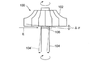
- the two are separately manufactured by using an electron beam welding etc. That is, as shown in FIG. 5, in the conventional turbine rotor 100, the electron beam E is applied in the direction perpendicular to the axial direction to the joint surface 106 of the turbine wheel 102 and the rotor shaft 104, and both are rotated. Is to be welded all around.
- Patent Documents 1 and 2 disclose a method of welding a turbine wheel and a rotor shaft using an electron beam.
- the welding method disclosed in Patent Document 1 is a method of connecting a turbine wheel formed of a heat-resistant metal and a rotor shaft, and rotating the turbine wheel and the rotor shaft while bonding them, and an electron beam at the bonding portion Irradiate and weld. Thereafter, the electron beam is irradiated while scanning a predetermined width toward the rotor shaft side from the bonding portion, and the rotor shaft in the vicinity of the bonding portion hardened by the thermal effect at the time of welding is tempered.
- Patent Document 1 performs welding by irradiating the electron beam to the joint and welding it, and then irradiating it while scanning the electron beam in the vicinity of the axial side of the joint hardened due to heat effect. Therefore, it aims at what is called a production technical solution which becomes possible to carry out welding processing continuously, and does not aim at elimination of the fall of a rotor shaft.
- Patent Document 1 only by tempering the rotor shaft side region, the falling of the rotor shaft is not eliminated. For this reason, if the rotor shaft after welding falls, the yield of the turbine rotor decreases. In addition, in order to correct the shaft center collapse by machining, two processes of a welding process and a machining process are required, and the productivity of the turbine rotor is greatly reduced. On the other hand, although the welding method of Patent Document 2 seems to be effective in suppressing residual stress that is biased in the circumferential direction, it requires a plurality of electron beam devices, resulting in a problem of high cost.
- the present invention is a low-cost device that suppresses the collapse of the rotor shaft after welding to improve the yield and improve the productivity of the turbine rotor to enable mass production.
- the purpose is to realize a rotor.
- the present invention relates to a turbine rotor in which a turbine wheel made of a heat resistant metal and a rotor shaft made of carbon steel are connected by butt welding,
- the turbine wheel and the rotor shaft have a structure formed by irradiating and welding a heat generating beam from a heat generating beam generator to a junction thereof, Local angle distribution of the rotor shaft generated at the time of welding by irradiating the electromagnetic energy or thermal energy adjusted to a fixed amount from the energy generator while scanning the rotor shaft side including the butt welding position of the joint with a predetermined width Temper to generate the residual stress of the entire circumference, and the axial center inclination generated around the outer periphery of the turbine wheel is suppressed to 0.2 mm or less during operation of the turbine rotor.
- the energy generator used for the tempering may be a high frequency induction heater or a laser beam generator, and more preferably, the heat generating beam generator used for welding is a laser beam or electron beam generator. Is good.
- the material of the rotor shaft is made of carbon steel which has a relatively high heat conductivity and a large heat capacity with respect to a turbine wheel made of a heat resistant metal.
- the amount of thermal expansion or thermal contraction of the rotor shaft due to tempering after welding is made relatively large compared to the turbine wheel. Therefore, residual stress over the entire circumference can be generated in the welded portion in tempering to be described later.
- the turbine wheel and the rotor shaft have a structure formed by irradiating and welding a laser beam or an electron beam (hereinafter referred to as a heat generation beam) to the joint portion.
- a heat generation beam (for example, a high frequency induction heating device or a laser beam) composed of electromagnetic energy or thermal energy adjusted to a fixed amount from the energy generator while scanning the rotor shaft side including the butt welding position of the joint with a predetermined width ), And tempering is performed so that the residual stress of the local angular distribution of the rotor shaft generated at the time of welding is generated over the entire circumference.
- the turbine rotor thus tempered is in a state in which residual stresses are balanced in the circumferential direction, and the equilibrium state is maintained even after cooling. Therefore, the rotor shaft does not fall and does not occur even if it is heated during operation. That is, at the time of operation of the turbine rotor, the axial center collapse ⁇ generated on the outer periphery of the turbine wheel can be suppressed to 0.2 mm or less. By setting the axial center inclination ⁇ to 0.2 mm or less, it is possible to suppress the occurrence of substantial noise and shaft vibration during operation to an allowable range.
- tempering can be completed by one scan, and tempering work can be performed in a short time. Therefore, it is suitable for mass production of a turbine rotor.
- the present inventors have found from various experiments that when welding the joint surface in the circumferential direction, local stress remains in the welding end side angular region. The reason is that the thermal expansion of the rotor shaft is larger than that of the turbine wheel, so that during welding the thermal expansion of the rotor shaft in the vicinity of the weld causes a tensile force to be applied to the weld. It is considered that the greatest tensile force acts because it is exposed to the longest time.
- tempering of the turbine rotor it is preferable to carry out a large number of tempering treatments in the region excluding the end side angular region (region of about 0 to 90 °). For example, after welding one turn (360 °) or two turns (720 °) of the joint surface, the output is gradually reduced while rotating about a half turn (180 °), and the rotor shaft side area including the weld portion When tempering is performed for one turn or two turns, it is preferable to omit the end angle area of the tempering within the range of 270 to 360 °. As a result, since the rotor shaft expands in a region other than the end side region, residual stress is generated in the cooled weld portion, and therefore, residual stress can be generated uniformly over the entire circumference of the rotor shaft.
- a high frequency heating device or a laser beam generator may be used.
- the high-frequency heating device can be reduced in size and weight, and can generate power with high efficiency, so power can be saved and cost can be reduced.
- rapid heating to a high temperature is possible, which is suitable for mass production.
- the laser beam generator can obtain high power density, little heat input, little thermal influence on the peripheral part, and can control the irradiation position of the beam accurately.
- unlike the electron beam there is no need to hold the periphery of the weld in a vacuum. Therefore, cost can be reduced and it is suitable for mass production.
- the turbine rotor according to the present invention tempers the rotor shaft side area near the weld including the weld after welding between the turbine wheel and the rotor shaft, and the residual stress of the local angle distribution of the rotor shaft generated at the welding is all around Since generation is carried out over the entire area, it is possible to suppress the falling of the rotor shaft after cooling or in the subsequent operation. Therefore, it is possible to manufacture a turbine rotor at low cost without causing the rotor shaft to tilt. In addition, since correction work by machining after welding becomes unnecessary, the yield can be improved, and the manufacturing time can be shortened, which is suitable for mass production.
- FIG. 1 It is a front view of the welding apparatus using the electron beam of this invention. It is a front view of the tempering apparatus using the laser beam of this invention.
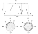
- (A) is a diagram which shows the heat processing process of the said embodiment
- (B) and (C) is sectional drawing of the welding part in the heat processing process.
- FIG. 1A shows a welding device for welding a turbine wheel 12 constituting a turbine rotor 10 and a rotor shaft 14.
- the chuck 22 is connected to the output shaft of the motor 20, and the lower end of the rotor shaft 14 is attached to the chuck 22.
- the rotor shaft 14 is rotated by the motor 20 together with the chuck 22.
- the upper end of the rotor shaft 14 is formed with a protrusion 14 a having a diameter smaller than that of the rotor shaft 14, while the center of the lower surface of the turbine wheel 12 is formed with a recess 12 a fitted with the protrusion 14 a.
- the turbine impeller 12 and the rotor shaft 14 are positioned relative to each other and rotate together.
- the turbine wheel 12 is made of a heat resistant material such as Inconel, and the rotor shaft 14 is made of carbon steel.
- the rotor shaft 14 is more thermally conductive than the turbine wheel 12 and has a larger heat capacity.
- the upper end center of the turbine wheel 12 is rotatably supported by the chuck 24, and the chuck 22 rotates the turbine wheel 12 in synchronization with the rotor shaft 14.
- the uneven surfaces 12 a and 14 a contact with each other to form the bonding surface 16.
- An electron beam generator 30 is provided in the vicinity of the position where the turbine wheel 10 is positioned, and the electron beam L is launched from the electron beam generator 30 toward the bonding surface 16.
- Reference numeral 300 denotes a vacuum valve which maintains the vacuum in the vacuum chamber 301.
- the turbine wheel 12 and the rotor shaft 14 are fitted by the uneven portions 12a and 14a, and in this state, the motor 20 is rotated to rotate the turbine wheel 12 and the rotor shaft 14.
- the electron beam generator 30 generates an electron beam L.
- the electron beam L is focused on the center side by the focusing lens 34 and irradiated toward the bonding surface 16.
- the peripheral portion of the bonding surface 16 is heated and melted, and the bonding surface 16 is welded.
- FIG. 2A shows a heat treatment process of the present embodiment using the electron beam generator 30.
- the temperature is raised from room temperature to 450 to 550 ° C., and the preheating step A is performed over the entire circumference.
- the welding process B of irradiating the bonding surface 16 with the electron beam L from the electron beam generator 30 and raising the temperature to 1500 to 1700 ° C. is carried out for one round (360 °) over the entire circumference, and then about The power is gradually reduced during the half rotation (180 °) to complete the welding.
- FIG. 1B is a tempering device for tempering the welded joint surfaces.
- a condensing lens 34 is provided inside the duct 32, and the laser beam L is condensed by the condensing lens 34 and then irradiated to the bonding surface 16.
- a branch duct 36 is provided in the duct 32, and a shield gas S such as argon or helium is supplied to the branch duct 36.
- the shielding gas S is supplied around the laser beam L irradiated toward the bonding surface 16 as a blocking gas for preventing the oxidation of the molten metal.
- a tempering step C is performed.
- the rotor shaft side region X in the vicinity of the weld zone including the weld zone is heated at a temperature of 400 to 750 ° C. and air cooled by a high frequency heat source or laser beam L.
- the laser beam L is scanned to perform tempering for one round (360 °) or two rounds (720 °) of the region X. In this case, it is most preferable not to irradiate the laser beam L in the range of 0 to 90 ° of the end side angular region.
- the polarization of the laser beam L is made possible by providing a reflective boundary (not shown) inside the laser beam generator 30 'and reflecting the laser beam L on this reflective boundary.
- FIG. 3 shows a case where welding of one turn to the joint surface 16 is performed, and then tempering of [one turn (360 °) -90 °] to the rotor shaft side region X including the welded portion is performed.
- the welding process B irradiation is started from the start point of 0 °, and the irradiation position is rotated by 1 around the bonding surface 16 and irradiated to the peripheral portion of the bonding surface 16 until it returns to the 0 ° position.
- the tempering step C the laser beam L is polarized to the rotor shaft side region X including the welded portion. Then, irradiation of the laser beam L is started from the position of 0 °, and irradiation is performed up to the range of 270 °.
- FIG. 4 shows the difference in the degree of concentration of the laser beam L on the irradiation target.
- the laser beam L 1 indicates the degree of concentration in the welding process B.
- the condensing lens 34 condenses one point on the joint surface 16 to increase the degree of condensation.
- high power density can be obtained, and melting can occur instantaneously, enabling high-speed welding and shortening welding time.
- a laser beam for welding as well as an electron beam.
- the light collection range of the laser beam L 2 as shown in FIG. 1B, and FIG. 4 is dispersed to correspond to the range of the rotor shaft side region X including the weld.
- the power density can be lowered until the required heating temperature in the tempering step C is obtained, and by expanding the light collection range, these can be irradiated by one rotation to the rotor shaft side region X including the weld portion. It can illuminate the whole area. Irradiating an electron beam or a laser beam toward the laser beam L 1 or L 2 to the rotor shaft side region X including the joint surface 16 or welds in such manner.
- FIG. 2B shows the occurrence of residual stress in the weld 40 at point D in FIG. 2A after the welding process B has been performed.
- the residual stress R 1 in the 270 ° after the end-side angle region is generating 0 ° as a starting point.
- the welding end side angle region the welding heat is exposed to the longest time, so the thermal expansion of the rotor shaft in the vicinity of the welding portion causes the largest tensile force to act. It is believed that the local residual stress will occur.
- the rotor shaft 14 does not fall and does not occur even if it is heated during operation.
- the turbine rotor 10 when the turbine rotor 10 is incorporated into a turbocharger for a vehicle, it is possible to suppress the axial center inclination ⁇ generated on the outer periphery of the turbine wheel to 0.2 mm or less during operation of the turbocharger for a vehicle. By setting the axial center inclination ⁇ to 0.2 mm or less, it is possible to suppress the occurrence of substantial noise and shaft vibration during operation to an allowable range.
- high power density can be obtained by using at least the laser beam generator 30. Therefore, high-speed welding is possible, which is suitable for mass production.
- the heat input is small, the thermal influence on the peripheral portion is small, and the irradiation position of the beam can be accurately controlled.
- the tempering step C the condensing range of the laser beam L is made to coincide with the rotor shaft side region X including the welded portion, so the tempering step C can be completed only by rotating the turbine rotor 10 once or twice. And tempering step C can be shortened.
- a high frequency heating device may be used instead.
- the high-frequency heating device can reduce the size and weight of the device, and can perform high-efficiency power generation, thereby saving power and reducing costs.
- rapid high-temperature heating is possible, it is suitable for mass production, and the heating temperature can be precisely controlled without contact by a high frequency magnetic field.
- the present invention it is possible to suppress the axial center inclination of the rotor shaft after welding, and thereby it is possible to improve the yield and to realize a turbine rotor capable of mass production at low cost.
Landscapes
- Engineering & Computer Science (AREA)
- Mechanical Engineering (AREA)
- Chemical & Material Sciences (AREA)
- Physics & Mathematics (AREA)
- Organic Chemistry (AREA)
- Crystallography & Structural Chemistry (AREA)
- Materials Engineering (AREA)
- Metallurgy (AREA)
- Thermal Sciences (AREA)
- General Engineering & Computer Science (AREA)
- Optics & Photonics (AREA)
- Plasma & Fusion (AREA)
- Welding Or Cutting Using Electron Beams (AREA)
- Supercharger (AREA)
- Heat Treatment Of Articles (AREA)
- Laser Beam Processing (AREA)
Priority Applications (3)
| Application Number | Priority Date | Filing Date | Title |
|---|---|---|---|
| EP13754668.5A EP2821617B1 (en) | 2012-02-28 | 2013-02-26 | Method of manufacturing a turbine rotor |
| US14/380,603 US9797256B2 (en) | 2012-02-28 | 2013-02-26 | Turbine rotor |
| CN201380011085.7A CN104136737B (zh) | 2012-02-28 | 2013-02-26 | 涡轮转子 |
Applications Claiming Priority (2)
| Application Number | Priority Date | Filing Date | Title |
|---|---|---|---|
| JP2012-041957 | 2012-02-28 | ||
| JP2012041957A JP5912659B2 (ja) | 2012-02-28 | 2012-02-28 | タービンロータ |
Publications (1)
| Publication Number | Publication Date |
|---|---|
| WO2013129408A1 true WO2013129408A1 (ja) | 2013-09-06 |
Family
ID=49082605
Family Applications (1)
| Application Number | Title | Priority Date | Filing Date |
|---|---|---|---|
| PCT/JP2013/054987 Ceased WO2013129408A1 (ja) | 2012-02-28 | 2013-02-26 | タービンロータ |
Country Status (5)
| Country | Link |
|---|---|
| US (1) | US9797256B2 (https=) |
| EP (1) | EP2821617B1 (https=) |
| JP (1) | JP5912659B2 (https=) |
| CN (1) | CN104136737B (https=) |
| WO (1) | WO2013129408A1 (https=) |
Cited By (2)
| Publication number | Priority date | Publication date | Assignee | Title |
|---|---|---|---|---|
| US10961603B2 (en) | 2013-11-25 | 2021-03-30 | Magna International Inc. | Structural component including a tempered transition zone |
| JP7729967B1 (ja) * | 2024-11-18 | 2025-08-26 | 三菱重工業株式会社 | シールフィンの補修方法 |
Families Citing this family (12)
| Publication number | Priority date | Publication date | Assignee | Title |
|---|---|---|---|---|
| DE102012207271A1 (de) * | 2012-05-02 | 2013-11-07 | Robert Bosch Gmbh | Verfahren zum Verbinden einer Welle mit einem Rotationsbauteil und nach diesem Verfahren hergestellte Turboladerwelle |
| US9664050B2 (en) * | 2013-10-25 | 2017-05-30 | Ecomotors, Inc. | Bearings for a turbomachine having an electric motor |
| US10041351B2 (en) * | 2014-09-16 | 2018-08-07 | Honeywell International Inc. | Turbocharger shaft and wheel assembly |
| US10024166B2 (en) * | 2014-09-16 | 2018-07-17 | Honeywell International Inc. | Turbocharger shaft and wheel assembly |
| CN104500268A (zh) * | 2014-12-12 | 2015-04-08 | 常州环能涡轮动力股份有限公司 | 具有双面离心压轮的微型涡轮喷气发动机 |
| CN104842033A (zh) * | 2015-05-05 | 2015-08-19 | 柳州金茂机械有限公司 | 一种定子焊接工艺 |
| CN104842032A (zh) * | 2015-05-05 | 2015-08-19 | 柳州金茂机械有限公司 | 一种转子焊接工艺 |
| CN106001923B (zh) * | 2016-06-15 | 2018-06-29 | 湖南天雁机械有限责任公司 | 一种涡轮增压器的涡轮转子激光复合加工方法 |
| CN108447432B (zh) * | 2017-02-16 | 2021-09-03 | 联咏科技股份有限公司 | 显示系统、电子装置及其显示调整方法 |
| DE102019210430A1 (de) * | 2019-07-15 | 2021-01-21 | Siemens Aktiengesellschaft | Elektronenstrahlschweißen von Nickelbasis-Superlegierungen und Vorrichtung |
| DE102019210423A1 (de) * | 2019-07-15 | 2021-01-21 | Siemens Aktiengesellschaft | Elektronenstrahlschweißen von Nickelbasis-Superlegierungen und Vorrichtung |
| KR102593470B1 (ko) * | 2021-08-05 | 2023-10-24 | 진성정밀금속(주) | 터빈 휠과 로터 샤프트의 전자빔 용접시스템 및 방법 |
Citations (5)
| Publication number | Priority date | Publication date | Assignee | Title |
|---|---|---|---|---|
| JPH04167995A (ja) * | 1990-10-31 | 1992-06-16 | Ngk Spark Plug Co Ltd | 金属回転体の製造方法 |
| JPH07286528A (ja) | 1994-04-19 | 1995-10-31 | N D K Kako Center Kk | タービンロータ軸の電子ビーム接合方法 |
| JP2001254627A (ja) | 2000-03-13 | 2001-09-21 | Ishikawajima Hanyou Kikai Kk | 過給機のタービンロータ軸の加工方法 |
| WO2006087074A1 (de) * | 2005-02-18 | 2006-08-24 | Daimlerchrysler Ag | Verbindungeiner welle mit einem turbinenrad eines abgasturboladers |
| JP2009203807A (ja) * | 2008-02-26 | 2009-09-10 | Mitsubishi Heavy Ind Ltd | タービンロータ及びロータの製造方法 |
Family Cites Families (17)
| Publication number | Priority date | Publication date | Assignee | Title |
|---|---|---|---|---|
| US3421201A (en) * | 1964-12-03 | 1969-01-14 | Caterpillar Tractor Co | Turbochargers |
| JPS58178804A (ja) * | 1982-04-14 | 1983-10-19 | Hitachi Ltd | 蒸気タ−ビンロ−タシヤフト |
| US4719074A (en) * | 1984-03-29 | 1988-01-12 | Ngk Insulators, Ltd. | Metal-ceramic composite article and a method of producing the same |
| JPH037367Y2 (https=) * | 1985-05-31 | 1991-02-25 | ||
| JPH0672616B2 (ja) * | 1987-04-21 | 1994-09-14 | 株式会社ゼクセル | 鋼シャフト複合アルミニウム合金ローター |
| JPH0774613B2 (ja) * | 1990-01-10 | 1995-08-09 | 日本碍子株式会社 | セラミックターボチャージャロータの製造方法 |
| JP2002235547A (ja) * | 2001-02-09 | 2002-08-23 | Shozo Shimizu | ターボチャージャ用タービン軸の接合方法 |
| US7089728B2 (en) * | 2003-12-17 | 2006-08-15 | Ingersoll-Rand Energy Systems Corporation | Single-piece turbine rotor and pinion gear and manufacturing technique for same |
| US7287960B2 (en) * | 2004-07-28 | 2007-10-30 | B{dot over (o)}rgWarner, Inc. | Titanium aluminide wheel and steel shaft connection thereto |
| JP4579778B2 (ja) | 2004-08-17 | 2010-11-10 | ルネサスエレクトロニクス株式会社 | センサ用電源回路およびそれを用いたマイクロホンユニット |
| JP4939098B2 (ja) * | 2006-04-05 | 2012-05-23 | 三菱重工業株式会社 | 管体の残留応力改善方法及び残留応力改善装置 |
| JP5199579B2 (ja) * | 2007-01-12 | 2013-05-15 | 三菱重工業株式会社 | 管体の残留応力改善方法及び装置 |
| EP2141252A1 (en) * | 2007-04-20 | 2010-01-06 | Mitsubishi Heavy Industries, Ltd. | Method and device for improving residual stress in pipe body |
| JP4495199B2 (ja) * | 2007-09-11 | 2010-06-30 | 三菱重工業株式会社 | タービンロータ及びロータの製造方法 |
| US20100154214A1 (en) * | 2008-12-18 | 2010-06-24 | Nelson Stud Welding, Inc. | Turbine wheel and shaft joining processes |
| JP5573295B2 (ja) * | 2010-03-30 | 2014-08-20 | トヨタ自動車株式会社 | タービンローターの製造方法 |
| CN101844271A (zh) * | 2010-05-20 | 2010-09-29 | 西北工业大学 | 钛铝合金涡轮与42CrMo调质钢轴的摩擦焊接方法 |
-
2012
- 2012-02-28 JP JP2012041957A patent/JP5912659B2/ja active Active
-
2013
- 2013-02-26 EP EP13754668.5A patent/EP2821617B1/en active Active
- 2013-02-26 US US14/380,603 patent/US9797256B2/en not_active Expired - Fee Related
- 2013-02-26 CN CN201380011085.7A patent/CN104136737B/zh not_active Expired - Fee Related
- 2013-02-26 WO PCT/JP2013/054987 patent/WO2013129408A1/ja not_active Ceased
Patent Citations (5)
| Publication number | Priority date | Publication date | Assignee | Title |
|---|---|---|---|---|
| JPH04167995A (ja) * | 1990-10-31 | 1992-06-16 | Ngk Spark Plug Co Ltd | 金属回転体の製造方法 |
| JPH07286528A (ja) | 1994-04-19 | 1995-10-31 | N D K Kako Center Kk | タービンロータ軸の電子ビーム接合方法 |
| JP2001254627A (ja) | 2000-03-13 | 2001-09-21 | Ishikawajima Hanyou Kikai Kk | 過給機のタービンロータ軸の加工方法 |
| WO2006087074A1 (de) * | 2005-02-18 | 2006-08-24 | Daimlerchrysler Ag | Verbindungeiner welle mit einem turbinenrad eines abgasturboladers |
| JP2009203807A (ja) * | 2008-02-26 | 2009-09-10 | Mitsubishi Heavy Ind Ltd | タービンロータ及びロータの製造方法 |
Non-Patent Citations (1)
| Title |
|---|
| See also references of EP2821617A4 |
Cited By (2)
| Publication number | Priority date | Publication date | Assignee | Title |
|---|---|---|---|---|
| US10961603B2 (en) | 2013-11-25 | 2021-03-30 | Magna International Inc. | Structural component including a tempered transition zone |
| JP7729967B1 (ja) * | 2024-11-18 | 2025-08-26 | 三菱重工業株式会社 | シールフィンの補修方法 |
Also Published As
| Publication number | Publication date |
|---|---|
| US20150037160A1 (en) | 2015-02-05 |
| CN104136737B (zh) | 2018-06-05 |
| EP2821617A4 (en) | 2015-12-09 |
| US9797256B2 (en) | 2017-10-24 |
| EP2821617B1 (en) | 2019-12-11 |
| CN104136737A (zh) | 2014-11-05 |
| JP2013177850A (ja) | 2013-09-09 |
| JP5912659B2 (ja) | 2016-04-27 |
| EP2821617A1 (en) | 2015-01-07 |
Similar Documents
| Publication | Publication Date | Title |
|---|---|---|
| JP5912659B2 (ja) | タービンロータ | |
| JP2013177850A5 (https=) | ||
| JP2010151127A (ja) | ガスタービンエンジンの溶接ロータを製造する方法 | |
| US20100288738A1 (en) | Welding apparatus and method | |
| JP4495199B2 (ja) | タービンロータ及びロータの製造方法 | |
| WO2007116805A1 (ja) | 管体の残留応力改善方法及び残留応力改善装置 | |
| RU2004101038A (ru) | Вал транспортного средства и способ и устройство для его изготовления | |
| JP5771399B2 (ja) | クランクシャフトへの焼入方法及びそのクランクシャフト | |
| JPH0431008B2 (https=) | ||
| JP4304190B2 (ja) | タービンホイールとロータシャフトの接合方法 | |
| US8437628B1 (en) | Method and apparatus of heat treating an integrally bladed rotor | |
| JP4179009B2 (ja) | クランクシャフトの製造方法 | |
| JP2002129239A (ja) | レーザ焼入れ方法及び装置 | |
| JP6143635B2 (ja) | レーザ溶接方法及びレーザ溶接装置 | |
| JP5495674B2 (ja) | 溶接装置、溶接方法 | |
| RU2815690C1 (ru) | Способ изготовления барабанно-дисковых секций ротора турбомашины | |
| WO2012105326A1 (ja) | 溶接方法及び溶接装置 | |
| JP4406939B2 (ja) | 鋼部材の溶接方法 | |
| JP2003231914A (ja) | レーザ焼入れ方法 | |
| JPH03294078A (ja) | レーザ加工方法 | |
| JP2009293076A (ja) | 熱処理方法 | |
| JPH11151587A (ja) | 円筒部材の溶接方法及び円筒体 | |
| CN115178753A (zh) | 抑制裂纹装置及方法 | |
| JPS6338516A (ja) | レ−ザ焼入れ方法 | |
| JP3849638B2 (ja) | カムの焼入れ方法 |
Legal Events
| Date | Code | Title | Description |
|---|---|---|---|
| 121 | Ep: the epo has been informed by wipo that ep was designated in this application |
Ref document number: 13754668 Country of ref document: EP Kind code of ref document: A1 |
|
| WWE | Wipo information: entry into national phase |
Ref document number: 14380603 Country of ref document: US Ref document number: 2013754668 Country of ref document: EP |
|
| NENP | Non-entry into the national phase |
Ref country code: DE |