WO2013129206A1 - 車両用ドア開閉装置 - Google Patents
車両用ドア開閉装置 Download PDFInfo
- Publication number
- WO2013129206A1 WO2013129206A1 PCT/JP2013/054193 JP2013054193W WO2013129206A1 WO 2013129206 A1 WO2013129206 A1 WO 2013129206A1 JP 2013054193 W JP2013054193 W JP 2013054193W WO 2013129206 A1 WO2013129206 A1 WO 2013129206A1
- Authority
- WO
- WIPO (PCT)
- Prior art keywords
- cable
- terminal
- vehicle
- guide roller
- door opening
- Prior art date
- Legal status (The legal status is an assumption and is not a legal conclusion. Google has not performed a legal analysis and makes no representation as to the accuracy of the status listed.)
- Ceased
Links
Images



Classifications
-
- E—FIXED CONSTRUCTIONS
- E05—LOCKS; KEYS; WINDOW OR DOOR FITTINGS; SAFES
- E05D—HINGES OR SUSPENSION DEVICES FOR DOORS, WINDOWS OR WINGS
- E05D15/00—Suspension arrangements for wings
- E05D15/06—Suspension arrangements for wings for wings sliding horizontally more or less in their own plane
- E05D15/0621—Details, e.g. suspension or supporting guides
-
- B—PERFORMING OPERATIONS; TRANSPORTING
- B60—VEHICLES IN GENERAL
- B60J—WINDOWS, WINDSCREENS, NON-FIXED ROOFS, DOORS, OR SIMILAR DEVICES FOR VEHICLES; REMOVABLE EXTERNAL PROTECTIVE COVERINGS SPECIALLY ADAPTED FOR VEHICLES
- B60J5/00—Doors
- B60J5/04—Doors arranged at the vehicle sides
- B60J5/06—Doors arranged at the vehicle sides slidable; foldable
-
- B—PERFORMING OPERATIONS; TRANSPORTING
- B60—VEHICLES IN GENERAL
- B60J—WINDOWS, WINDSCREENS, NON-FIXED ROOFS, DOORS, OR SIMILAR DEVICES FOR VEHICLES; REMOVABLE EXTERNAL PROTECTIVE COVERINGS SPECIALLY ADAPTED FOR VEHICLES
- B60J5/00—Doors
- B60J5/04—Doors arranged at the vehicle sides
- B60J5/0468—Fixation or mounting means specific for door components
-
- B—PERFORMING OPERATIONS; TRANSPORTING
- B60—VEHICLES IN GENERAL
- B60J—WINDOWS, WINDSCREENS, NON-FIXED ROOFS, DOORS, OR SIMILAR DEVICES FOR VEHICLES; REMOVABLE EXTERNAL PROTECTIVE COVERINGS SPECIALLY ADAPTED FOR VEHICLES
- B60J5/00—Doors
- B60J5/04—Doors arranged at the vehicle sides
- B60J5/047—Doors arranged at the vehicle sides characterised by the opening or closing movement
-
- E—FIXED CONSTRUCTIONS
- E05—LOCKS; KEYS; WINDOW OR DOOR FITTINGS; SAFES
- E05D—HINGES OR SUSPENSION DEVICES FOR DOORS, WINDOWS OR WINGS
- E05D15/00—Suspension arrangements for wings
- E05D15/06—Suspension arrangements for wings for wings sliding horizontally more or less in their own plane
- E05D15/10—Suspension arrangements for wings for wings sliding horizontally more or less in their own plane movable out of one plane into a second parallel plane
- E05D15/1042—Suspension arrangements for wings for wings sliding horizontally more or less in their own plane movable out of one plane into a second parallel plane with transversely moving carriage
- E05D15/1047—Suspension arrangements for wings for wings sliding horizontally more or less in their own plane movable out of one plane into a second parallel plane with transversely moving carriage specially adapted for vehicles
-
- E—FIXED CONSTRUCTIONS
- E05—LOCKS; KEYS; WINDOW OR DOOR FITTINGS; SAFES
- E05F—DEVICES FOR MOVING WINGS INTO OPEN OR CLOSED POSITION; CHECKS FOR WINGS; WING FITTINGS NOT OTHERWISE PROVIDED FOR, CONCERNED WITH THE FUNCTIONING OF THE WING
- E05F15/00—Power-operated mechanisms for wings
- E05F15/60—Power-operated mechanisms for wings using electrical actuators
- E05F15/603—Power-operated mechanisms for wings using electrical actuators using rotary electromotors
- E05F15/632—Power-operated mechanisms for wings using electrical actuators using rotary electromotors for horizontally-sliding wings
- E05F15/643—Power-operated mechanisms for wings using electrical actuators using rotary electromotors for horizontally-sliding wings operated by flexible elongated pulling elements, e.g. belts, chains or cables
- E05F15/646—Power-operated mechanisms for wings using electrical actuators using rotary electromotors for horizontally-sliding wings operated by flexible elongated pulling elements, e.g. belts, chains or cables allowing or involving a secondary movement of the wing, e.g. rotational or transversal
-
- E—FIXED CONSTRUCTIONS
- E05—LOCKS; KEYS; WINDOW OR DOOR FITTINGS; SAFES
- E05D—HINGES OR SUSPENSION DEVICES FOR DOORS, WINDOWS OR WINGS
- E05D15/00—Suspension arrangements for wings
- E05D15/06—Suspension arrangements for wings for wings sliding horizontally more or less in their own plane
- E05D15/10—Suspension arrangements for wings for wings sliding horizontally more or less in their own plane movable out of one plane into a second parallel plane
- E05D15/1042—Suspension arrangements for wings for wings sliding horizontally more or less in their own plane movable out of one plane into a second parallel plane with transversely moving carriage
- E05D2015/1055—Suspension arrangements for wings for wings sliding horizontally more or less in their own plane movable out of one plane into a second parallel plane with transversely moving carriage with slanted or curved track sections or cams
-
- E—FIXED CONSTRUCTIONS
- E05—LOCKS; KEYS; WINDOW OR DOOR FITTINGS; SAFES
- E05Y—INDEXING SCHEME ASSOCIATED WITH SUBCLASSES E05D AND E05F, RELATING TO CONSTRUCTION ELEMENTS, ELECTRIC CONTROL, POWER SUPPLY, POWER SIGNAL OR TRANSMISSION, USER INTERFACES, MOUNTING OR COUPLING, DETAILS, ACCESSORIES, AUXILIARY OPERATIONS NOT OTHERWISE PROVIDED FOR, APPLICATION THEREOF
- E05Y2201/00—Constructional elements; Accessories therefor
- E05Y2201/60—Suspension or transmission members; Accessories therefor
- E05Y2201/622—Suspension or transmission members elements
- E05Y2201/644—Flexible elongated pulling elements
- E05Y2201/654—Cables
-
- E—FIXED CONSTRUCTIONS
- E05—LOCKS; KEYS; WINDOW OR DOOR FITTINGS; SAFES
- E05Y—INDEXING SCHEME ASSOCIATED WITH SUBCLASSES E05D AND E05F, RELATING TO CONSTRUCTION ELEMENTS, ELECTRIC CONTROL, POWER SUPPLY, POWER SIGNAL OR TRANSMISSION, USER INTERFACES, MOUNTING OR COUPLING, DETAILS, ACCESSORIES, AUXILIARY OPERATIONS NOT OTHERWISE PROVIDED FOR, APPLICATION THEREOF
- E05Y2201/00—Constructional elements; Accessories therefor
- E05Y2201/60—Suspension or transmission members; Accessories therefor
- E05Y2201/622—Suspension or transmission members elements
- E05Y2201/658—Members cooperating with flexible elongated pulling elements
-
- E—FIXED CONSTRUCTIONS
- E05—LOCKS; KEYS; WINDOW OR DOOR FITTINGS; SAFES
- E05Y—INDEXING SCHEME ASSOCIATED WITH SUBCLASSES E05D AND E05F, RELATING TO CONSTRUCTION ELEMENTS, ELECTRIC CONTROL, POWER SUPPLY, POWER SIGNAL OR TRANSMISSION, USER INTERFACES, MOUNTING OR COUPLING, DETAILS, ACCESSORIES, AUXILIARY OPERATIONS NOT OTHERWISE PROVIDED FOR, APPLICATION THEREOF
- E05Y2900/00—Application of doors, windows, wings or fittings thereof
- E05Y2900/50—Application of doors, windows, wings or fittings thereof for vehicles
- E05Y2900/53—Type of wing
- E05Y2900/531—Doors
Definitions
- the present invention relates to a vehicle door opening / closing device for driving a vehicle door used for opening / closing a door opening formed in a vehicle body.
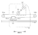
- the vehicle door opening and closing device includes a guide rail 91 fixed to a side portion of the vehicle body, is fixed to the vehicle door 92, and is movably engaged with the guide rail 91.
- a guide roller member 93 is provided.
- the vehicle body is provided with an electric motor 97 as a drive source. Both ends 95 a and 95 b of the cable 95 that can be selectively wound and fed are connected to the guide roller member 93 by a drum 96 that is rotationally driven by the electric motor 97.
- Cables 95 extending from the drum 96 along the vehicle front-rear direction are respectively hung on a pair of pulleys 94a and 94b disposed on the front and rear sides of the guide rail 91, and circulate between the pulleys 94a and 94b. Both terminals 95a and 95b are connected to a guide roller member 93, respectively.
- the front end of the guide rail is located on the movement locus of the guide roller member in the vicinity of the fully closed position of the vehicle door.
- the front end of the guide rail is located inside the vehicle width direction so as to push the vehicle door outward in the vehicle width direction immediately after opening from the fully closed position, or to pull the vehicle door inward in the vehicle width direction immediately before the fully closed position. (See Patent Document 2). Therefore, in the fully closed position of the vehicle door, the front pulley 94b that is spaced forward from the front terminal 95b of the cable 95 is disposed on the inner side in the vehicle width direction according to the curve of the guide rail.
- the object of the present invention is to provide a sufficient clearance between the end of the cable and the front pulley without increasing the amount of expansion of the arrangement space required for parts such as the front pulley arranged on the front side of the guide rail into the vehicle interior.
- Another object of the present invention is to provide a vehicle door opening and closing device that can be secured.
- the present invention is configured to be disposed on a quarter panel behind a door opening formed on a side portion of a vehicle body, and is a bent portion that is inclined toward a vehicle interior at a front end portion.
- a guide rail configured to extend in the front-rear direction, and a guide roller configured to be coupled to a vehicle door that opens and closes the door opening and is capable of rolling the guide rail
- a drive member configured to be fixed to the vehicle body, and having a drive source and a drum that is rotationally driven by the drive source; a front pulley disposed on the front side and a rear side of the guide rail; and a rear side A side pulley, and a cable wound around the drum and hooked on the front pulley and the rear pulley, respectively, and changed in direction and connected to the guide roller member at both ends.
- the cable portion for closing operation which is a portion extending from the front pulley of the cable to the guide roller member, is routed outside the guide rail, and the corresponding terminal is located behind the roller and is connected to the guide roller member.
- An opening operation cable portion that is connected and extends from the rear pulley of the cable to the guide roller member is routed in the guide rail, and the corresponding terminal is connected to the guide roller member.
- the cable portion for the closing operation of the cable is routed outside the guide rail, and the corresponding terminal is connected to the guide roller member behind the roller. Accordingly, the terminal of the closing operation cable portion in the fully closed position and the connecting portion of the guide roller member can be separated from the front pulley disposed in front of the terminal. For this reason, without increasing the amount of bulging into the vehicle compartment of the arrangement space required for parts such as the front pulley arranged on the front side of the bent portion of the guide rail, the terminal of the cable portion for closing operation and A sufficient clearance between the front pulleys can be ensured. And the reduction of the vehicle interior space and the deterioration of the appearance of the interior can be suppressed.
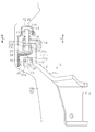
- FIG. 2 is a cross-sectional view showing a main part of the apparatus of FIG. 1.
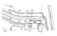
- the perspective view which shows the front side of a center rail, and its periphery structure.
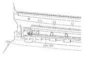
- the perspective view which shows the rear side of a center rail, and its periphery structure.
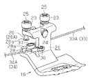
- the perspective view which shows the assembly
- the schematic diagram which shows vehicles, such as a motor vehicle, to which the apparatus of FIG. 1 is applied.
- the top view which shows the state by which a slide door is arrange
- the elements on larger scale which show a guide roller unit.
- the schematic diagram which shows a conventional form.
- the vehicle front-rear direction is referred to as “front-rear direction”, and the upper and lower directions in the vehicle height direction are referred to as “upward” and “downward”, respectively.
- the inner side in the vehicle width direction toward the vehicle interior is referred to as “vehicle inner side”
- the outer side in the vehicle width direction toward the vehicle outer side is referred to as “vehicle outer side”.
- the vehicle body 10 is provided with an upper rail 11 and a lower rail 12 that extend in the front-rear direction along the upper and lower edges of a door opening 10a formed on the side of the vehicle body 10, respectively.
- a center rail 13 as a guide rail extending in the front-rear direction is installed on the quarter panel 10b behind the door opening 10a.
- a slide door 20 as a vehicle door is supported by the upper rail 11, the lower rail 12 and the center rail 13 through a guide roller unit 14 and 15 and a guide roller unit 16 as a guide roller member so as to be movable in the front-rear direction. ing.
- the slide door 20 opens and closes the door opening 10a by sliding the guide roller units 14 to 16 on the upper rail 11, the lower rail 12, and the center rail 13 with the movement in the front-rear direction.
- the center rail 13 is formed of, for example, a metal plate, has a curved portion 13 a in the middle in the longitudinal direction, and extends along the front-rear direction, that is, the opening / closing direction of the slide door 20. ing.
- the center rail 13 includes the curved portion 13a, a bent portion 13b located at the front end, and a straight portion 13c.
- the bent portion 13b is inclined from the front end of the curved portion 13a toward the vehicle interior, and the straight portion 13c extends rearward from the rear end of the curved portion 13a.
- a trim or lining 50 that forms a design surface in the vehicle interior of the vehicle body 10 has a bulging portion 50 a that bulges toward the inside of the vehicle in accordance with the front end of the bent portion 13 b of the center rail 13.
- a front pulley 17 is rotatably supported on the vehicle body 10 so as to be positioned in the vicinity of the front end of the bent portion 13b of the center rail 13, and opposed to the rear end of the straight portion 13c of the center rail 13,
- the rear pulley 18 is rotatably supported.
- the front pulley 17 and the rear pulley 18 have axes that extend in the vehicle height direction.
- a driving member 30 is fixed to the vehicle body 10 so as to be positioned in the vicinity of the center rail 13.
- the drive member 30 includes a drive motor 31 as a drive source and a drum 32 that is rotationally driven by the drive motor 31.
- a front cable 33 and a rear cable 34 are wound around the drum 32 and are fixed to the drum 32 at their inner ends.
- the front cable 33 extends forward through the inside of the outer tube 35 routed between the drum 32 and the front pulley 17 and then is exposed to the outside.
- the front cable 33 is hung on the front pulley 17 and turned rearward. Yes.
- the rear cable 34 extends rearward through the inside of the outer tube 36 arranged between the drum 32 and the rear pulley 18 and is exposed to the outside, and is hung on the rear pulley 18 and forward. The direction has been changed.
- the center rail 13 has a substantially C-shaped cross-sectional shape that opens toward the outside of the vehicle and toward the slide door 20.
- the center rail 13 constitutes a first roller guide 13d at the lower wall portion, and constitutes a second roller guide 13e by folding the tip end portion of the upper wall portion downward.
- the guide roller unit 16 includes a base plate 21 made of, for example, a metal plate, a load roller 22, and a pair of front and rear vertical rollers 23.
- the base plate 21 is rotatably connected to a bracket 51 fixed to the slide door 20.
- the base plate 21 has a mounting wall portion 21a connected to the bracket 51 so as to be rotatable around an axis O1 extending in the vehicle height direction, and extends from the upper end of the mounting wall portion 21a so as to face the center rail 13. It has the extended wall part 21b to protrude.
- the base plate 21 has a standing wall portion 21c that rises from the front portion of the upper end of the extending wall portion 21b, and has a pair of front and rear support pieces 21d that bend inward from the upper end of the standing wall portion 21c.
- the load roller 22 is pivotally supported at the upper end of the standing wall 21c.
- the load roller 22 is pivotally supported around a support pin 24 that extends along an axis intersecting the center rail 13.
- the vertical roller 23 is pivotally supported on each support piece 21d. Specifically, the vertical roller 23 is pivotally supported around a support pin 25 extending along an axis O2 in the vehicle height direction.
- the support pin 25 penetrates the support piece 21d in the vehicle height direction, and pivotally supports the vertical roller 23 at the upper end portion thereof.
- a lower end portion of the support pin 25 penetrating the support piece 21d forms a substantially circular column portion 26 having a substantially circular flange 26a at the lower end.
- the column portion 26 is integrally formed with the support pin 25 so as to be disposed coaxially with the vertical roller 23.
- the base plate 21 has a support piece 21e that extends from the rear portion of the upper end of the extending wall portion 21b to the inside of the vehicle below the center rail 13.
- a support pin 27 extending along the axis O3 in the vehicle height direction is attached to the support piece 21e.
- An upper end portion of the support pin 27 that penetrates the support piece 21e forms a substantially cylindrical front cable connecting portion 28 having a substantially oval flange 28a at the upper end.
- the longitudinal direction of the flange 28a substantially coincides with the longitudinal direction of the center rail 13, that is, the front-rear direction. As shown in an enlarged view in FIG.
- the front cable connecting portion 28 is in the vicinity of the rear column portion 26 (hereinafter, also referred to as “rear cable connecting portion 26 ⁇ / b> A”) in plan view, more specifically in plan view.
- the rear cable connecting portion 26A is disposed so as to partially overlap.
- a portion of the front cable 33 that is hung on the front pulley 17 and turned rearward (hereinafter also referred to as a “closing operation cable portion 33 ⁇ / b> A”) is located below and outside the center rail 13.
- the terminal 37 is connected to the front cable connecting portion 28 by being routed. That is, as shown in FIG. 5A, the terminal 37 is formed in a substantially long cylindrical shape that opens along the vehicle height direction so that the flange 28a can be inserted, and the front cable connecting portion 28 is inserted into the terminal 37. As a result, the terminal 37 is locked in a state in which the terminal 37 is prevented from being detached from the flange 28a.
- the cable portion 33A for closing operation is prevented from falling off the terminal 37 from the front cable connecting portion 28 by generating a tension in the extending direction (front-rear direction) in the use state after assembly. Needless to say, the terminal 37 locked to the front cable connecting portion 28 is disposed behind the load roller 22.
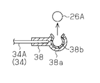
- a portion (hereinafter also referred to as “opening operation cable portion 34A”) that is hung on the rear pulley 18 of the rear cable 34 and turned forward is routed in the center rail 13 and the terminal 38 thereof. Is hooked to the rear cable connecting portion 26A. That is, as shown in FIG. 5B, the terminal 38 has a substantially semicircular holder 38a and a substantially ⁇ -shaped drop-off preventing member 38b made of a resin material fitted into the holder 38a. Both the holder 38a and the drop-off prevention member 38b are open toward the inside of the vehicle so as to face the rear cable connecting portion 26A.
- the drop preventing member 38b By pressing the terminal 38 against the rear cable connecting portion 26A along the opening direction of the holder 38a, the drop preventing member 38b is elastically deformed so as to expand. Accordingly, the rear cable connecting portion 26A is inserted into the drop-off preventing member 38b, and the terminal 38 is hooked to the rear cable connecting portion 26A in a state of being prevented from being detached from the flange 26a. Since the opening operation cable portion 34A is tensioned in the extending direction (front-rear direction, that is, the direction substantially orthogonal to the opening direction of the holder 38a) in the use state after assembly, the terminal from the rear cable connecting portion 26A is used. The omission of 38 is suppressed.
- a resin front case 41 is fastened to the quarter panel 10 b in accordance with the front end of the center rail 13, and the front case 41 is directly below the center rail 13, for example, A resin grommet 42 is fitted.
- the front case 41 is for rotatably accommodating the front pulley 17, and the grommet 42 has a front cable 33 (closed operation cable portion 33 ⁇ / b> A) whose direction is changed rearward in the front pulley 17 in the front case 41. It is for guiding to the lower side of the center rail 13, that is, the outside of the vehicle.
- an arcuate cable guide 43 made of, for example, a resin material is fixed to the quarter panel 10b so as to be directly below the curved portion 13a of the center rail 13.
- the cable guide 43 is for suppressing the closing operation cable portion 33A arranged below the center rail 13 along the shape of the center rail 13 having the curved portion 13a from contacting the quarter panel 10b. Is.
- the closing operation cable portion 33A is slidably contacted with the cable guide 43, thereby realizing the direction change at the bending portion 13a without contacting the quarter panel 10b.
- a resin rear case 46 is fastened to the quarter panel 10 b so as to face the rear end of the straight portion 13 c of the center rail 13 and to the rear thereof.
- a resin grommet 47 is fitted to the rear case 46.
- the rear case 46 is for rotatably accommodating the rear pulley 18, and the grommet 47 is a rear cable 34 (opening operation cable) whose direction is changed forward in the rear pulley 18 in the rear case 46. 34A) for guiding the inside of the center rail 13, that is, the outside of the vehicle.
- the guide roller unit 16 connected to the terminal 37 is moved along the center rail 13.
- the slide door 20 that moves forward and is coupled to the guide roller unit 16 moves forward, that is, closes.
- the terminal 37 is connected to the guide roller unit 16 behind the load roller 22 (front cable connecting portion 28), so that the terminal 37 and the front cable connecting portion 28 in the fully closed position are Separated from the front pulley 17.
- the terminal 37 and the front pulley of the cable portion 33A for the closing operation are not increased without increasing the amount of expansion of the arrangement space required for the front pulley 17 arranged on the front side of the bent portion 13b of the center rail 13 into the vehicle interior. A sufficient clearance between 17 is ensured.
- the cable portion 33A for closing operation of the front cable 33 is routed outside and below the center rail 13, and the terminal 37 is connected to the front cable connecting portion 28 of the guide roller unit 16 behind the load roller 22. Connected. Therefore, the terminal 37 and the front cable connecting portion 28 of the closing operation cable portion 33 ⁇ / b> A in the fully closed position can be separated from the front pulley 17 disposed in front of the terminal 37. For this reason, the terminal 37 and the front pulley of the cable portion 33A for the closing operation are not increased without increasing the amount of expansion of the arrangement space required for the front pulley 17 arranged on the front side of the bent portion 13b of the center rail 13 into the vehicle interior. A sufficient clearance between 17 can be secured.
- the reduction of the vehicle interior space, the deterioration of the appearance of the trim 50, etc. can be suppressed.
- a three-row seat vehicle such as a one-box vehicle or a minivan vehicle, it is possible to suppress deterioration in the ability to get on and off the third row seat.
- the terminal 37 of the closing operation cable portion 33A is disposed in the vicinity of the terminal 38 of the opening operation cable portion 34A in plan view. Therefore, the base plate 21 is seen in a plan view by arranging the terminals 37 and 38 of the closing operation cable portion 33A and the opening operation cable portion 34A, and the front cable connection portion 28 and the rear cable connection portion 26A in an integrated manner.
- the guide roller unit 16 including can be made smaller.
- the terminal 38 of the opening operation cable portion 34A is defined as the extending direction of the rear cable 34 (opening operation cable portion 34A) extending to the terminal 38, that is, the direction in which the tension acts on the rear cable 34.
- the guide roller unit 16 is connected from different directions (vehicle width direction). Therefore, the assembling property of the rear cable 34 can be improved.
- the terminal 37 of the closing operation cable portion 33A has a direction different from the extending direction of the front cable 33 (closing operation cable portion 33A) extending to the terminal 37, that is, the direction in which the tension acts on the front cable 33. It is connected to the guide roller unit 16 from (vehicle height direction). Therefore, the assembling property of the front cable 33 can be improved.
- the rear cable connecting portion 26A to which the terminal 38 of the opening operation cable portion 34A is connected is arranged coaxially with the rear vertical roller 23. Therefore, by arranging the rear cable connecting portion 26A and the rear vertical roller 23 collectively, the guide roller unit 16 including the base plate 21 can be made smaller in plan view. In particular, the number of parts can be reduced by integrally forming the support pin 25 of the vertical roller 23 and the rear cable connecting portion 26A.
- the dropout prevention member 38b of the terminal 38 may be made of metal.
- the terminal 37 of the front cable 33 may be configured with a holder and a drop-off preventing member in accordance with the terminal 38 of the rear cable 34.
- the terminal 38 of the rear cable 34 may be configured according to the terminal 37 of the front cable 33.
- At least one of the terminals 37, 38 may be hook-shaped.
- the shapes of the terminals 37 and 38 are arbitrary.
- the shape may be such that the corresponding terminals 37 and 38 are connected to the guide roller unit 16 by pulling them in the direction in which tension is applied to the closing operation cable portion 33A or the opening operation cable portion 34A.
- the rear cable connecting portion 26A to which the terminal 38 of the opening operation cable portion 34A is connected may not be arranged coaxially with the rear vertical roller 23.
- the portions do not necessarily overlap.
- the closing operation cable portion 33A of the front cable 33 may be routed above the center rail 13.
Landscapes
- Engineering & Computer Science (AREA)
- Mechanical Engineering (AREA)
- Power-Operated Mechanisms For Wings (AREA)
- Closing And Opening Devices For Wings, And Checks For Wings (AREA)
Description
曲成部13bは、湾曲部13aの前端から車内に向かって傾斜しており、直線部13cは、湾曲部13aの後端から後方に延びている。車両ボデー10の車室内の意匠面を形成するトリムすなわち内張50は、センターレール13の曲成部13bの前端に合わせて、車内に向かって膨出する膨出部50aを有する。車両ボデー10には、センターレール13の曲成部13bの前端付近に位置するように、前側プーリ17が回転自在に支持されるとともに、センターレール13の直線部13cの後端に対向して、後側プーリ18が回転自在に支持されている。前側プーリ17及び後側プーリ18は、車両高さ方向に延びる軸線を有する。
Claims (5)
- 車両ボデーの側部に形成されたドア開口の後方のクォータパネルに配置されるように構成され、前端部に車内に向かって傾斜する曲成部を有し、前後方向に延設されるように構成されたガイドレールと、
前記ドア開口を開閉する車両ドアに連結されるように構成され、前記ガイドレールを転動可能なローラを有するガイドローラ部材と、
前記車両ボデーに固定されるように構成され、駆動源及び該駆動源により回転駆動されるドラムを有する駆動部材と、
前記ガイドレールの前側及び後側に配設された前側プーリ及び後側プーリと、
前記ドラムに巻回され前記前側プーリ及び前記後側プーリにそれぞれ掛けられて方向転換され、両端末で前記ガイドローラ部材にそれぞれ連結されたケーブルとを備え、
前記ケーブルの前記前側プーリから前記ガイドローラ部材に延びる部位である閉作動用ケーブル部は、前記ガイドレールの外側に配索されて該当の前記端末が前記ローラよりも後方で前記ガイドローラ部材に連結されており、
前記ケーブルの前記後側プーリから前記ガイドローラ部材に延びる部位である開作動用ケーブル部は、前記ガイドレール内に配索されて該当の前記端末が前記ガイドローラ部材に連結されている、車両用ドア開閉装置。 - 請求項1に記載の車両用ドア開閉装置において、
前記閉作動用ケーブル部の前記端末は、平面視で前記開作動用ケーブル部の前記端末の近傍に配置されている、車両用ドア開閉装置。 - 請求項1又は2に記載の車両用ドア開閉装置において、
前記閉作動用ケーブル部及び前記開作動用ケーブル部の少なくとも一方の前記端末は、当該端末へと延びる前記ケーブルの延在方向とは異なる方向から前記ガイドローラ部材に連結されている、車両用ドア開閉装置。 - 請求項1~3のいずれか一項に記載の車両用ドア開閉装置において、
前記ガイドローラ部材は、平面視で前記ローラを挟むように前後方向に並設されて車両高さ方向に延びる軸線周りに回動しつつ前記ガイドレールを転動可能な一対のガイドローラを備え、
前記開作動用ケーブル部の前記端末が連結される前記ガイドローラ部材の連結部は、後方の前記ガイドローラと同軸に配置されている、車両用ドア開閉装置。 - 請求項3に記載の車両用ドア開閉装置において、
前記ケーブルの延在方向とは異なる方向から前記ガイドローラ部材に連結される当該端末は、
車内に向かって開口するホルダと、
前記ホルダ内に嵌着され、前記端末が連結される前記ガイドローラ部材の連結部が挿嵌される脱落防止部材とを有する、車両用ドア開閉装置。
Priority Applications (3)
| Application Number | Priority Date | Filing Date | Title |
|---|---|---|---|
| DE112013001244.8T DE112013001244B4 (de) | 2012-03-01 | 2013-02-20 | Vorrichtung zum Öffnen/Schliessen einer Fahrzeugtür |
| US14/378,238 US9151098B2 (en) | 2012-03-01 | 2013-02-20 | Vehicle door opening/closing device |
| CN201390000280.5U CN204152358U (zh) | 2012-03-01 | 2013-02-20 | 车辆用门开闭装置 |
Applications Claiming Priority (2)
| Application Number | Priority Date | Filing Date | Title |
|---|---|---|---|
| JP2012045709A JP5712952B2 (ja) | 2012-03-01 | 2012-03-01 | 車両用ドア開閉装置 |
| JP2012-045709 | 2012-03-01 |
Publications (1)
| Publication Number | Publication Date |
|---|---|
| WO2013129206A1 true WO2013129206A1 (ja) | 2013-09-06 |
Family
ID=49082406
Family Applications (1)
| Application Number | Title | Priority Date | Filing Date |
|---|---|---|---|
| PCT/JP2013/054193 Ceased WO2013129206A1 (ja) | 2012-03-01 | 2013-02-20 | 車両用ドア開閉装置 |
Country Status (5)
| Country | Link |
|---|---|
| US (1) | US9151098B2 (ja) |
| JP (1) | JP5712952B2 (ja) |
| CN (1) | CN204152358U (ja) |
| DE (1) | DE112013001244B4 (ja) |
| WO (1) | WO2013129206A1 (ja) |
Cited By (7)
| Publication number | Priority date | Publication date | Assignee | Title |
|---|---|---|---|---|
| CN105229251A (zh) * | 2014-02-07 | 2016-01-06 | 三井金属爱科特株式会社 | 用于打开和关闭车门的装置 |
| US9238399B2 (en) * | 2014-04-11 | 2016-01-19 | Aisin Technical Center Or America, Inc. | Slide structure for power slide door and cable assembly method for slide door center |
| CN105492228A (zh) * | 2014-08-06 | 2016-04-13 | 三井金属爱科特株式会社 | 门开闭装置 |
| CN105874141A (zh) * | 2013-12-25 | 2016-08-17 | 爱信精机株式会社 | 开闭体的开闭装置 |
| US9637968B2 (en) | 2015-06-03 | 2017-05-02 | Honda Motor Co., Ltd. | Center roller assembly for a vehicle slide door |
| US9803407B2 (en) | 2014-08-06 | 2017-10-31 | Mitsui Kinzoku Act Corporation | Door opening and closing apparatus |
| US9828796B2 (en) | 2014-08-06 | 2017-11-28 | Mitsui Kinzoku Act Corporation | Door opening and closing apparatus |
Families Citing this family (19)
| Publication number | Priority date | Publication date | Assignee | Title |
|---|---|---|---|---|
| KR20150074806A (ko) | 2013-12-24 | 2015-07-02 | 기아자동차주식회사 | 차량용 슬라이딩 도어 |
| KR101542981B1 (ko) * | 2013-12-27 | 2015-08-07 | 현대자동차 주식회사 | 차량의 프론트 도어장치 |
| CN107208448B (zh) * | 2015-02-04 | 2018-11-02 | 株式会社美姿把 | 辊单元和车用开闭体驱动装置 |
| JP6563837B2 (ja) * | 2016-03-17 | 2019-08-21 | 株式会社ミツバ | ローラ装置 |
| GB2550890B (en) * | 2016-05-27 | 2020-02-19 | Ford Global Tech Llc | A vehicle having a braked sliding door |
| CN106193865B (zh) * | 2016-07-28 | 2018-03-16 | 芜湖莫森泰克汽车科技股份有限公司 | 汽车电动滑门中铰链结构 |
| US10279662B2 (en) * | 2016-10-07 | 2019-05-07 | Honda Motor Co., Ltd. | Datum pin assembly |
| CN108442846A (zh) * | 2017-02-16 | 2018-08-24 | 深圳市祈飞科技有限公司 | 自动平开门 |
| JP6887884B2 (ja) * | 2017-06-02 | 2021-06-16 | 株式会社ミツバ | 車両用開閉装置 |
| DE102018105379B4 (de) * | 2018-03-08 | 2025-09-04 | Volkswagen Aktiengesellschaft | Kinematik für eine Schiebetür eines Kraftfahrzeuges sowie Schiebetür |
| DE102018126040B4 (de) * | 2018-10-19 | 2022-12-29 | Benteler Automobiltechnik Gmbh | Verbindungshülsenanordnung zum Verbinden von rohrförmigen Querträgern in einem Fahrzeug |
| JP7135814B2 (ja) * | 2018-12-10 | 2022-09-13 | 株式会社アイシン | ローラユニット |
| CN110203048A (zh) * | 2019-05-31 | 2019-09-06 | 苏州经贸职业技术学院 | 一种旋转侧开车门驱动装置 |
| US10967913B2 (en) * | 2019-08-28 | 2021-04-06 | Ford Global Technologies, Llc | Detachable quarter panel bracket |
| CN111042699B (zh) * | 2020-01-14 | 2025-04-22 | 广西京达科技有限公司 | 滑移门驱动机构、滑移门机构和移动机械 |
| JP7411306B2 (ja) * | 2021-05-11 | 2024-01-11 | 株式会社アイシン | ガイドレール |
| JP7642582B2 (ja) * | 2022-02-28 | 2025-03-10 | 矢崎総業株式会社 | ワイヤハーネス |
| CN115075681B (zh) * | 2022-07-28 | 2025-11-04 | 浙江吉利控股集团有限公司 | 一种滑移门开启装置及车辆 |
| US12291917B2 (en) * | 2023-07-26 | 2025-05-06 | Textron Innovations Inc. | Door management |
Citations (4)
| Publication number | Priority date | Publication date | Assignee | Title |
|---|---|---|---|---|
| JP2004257174A (ja) * | 2003-02-27 | 2004-09-16 | Aisin Seiki Co Ltd | スライドドア開閉装置 |
| JP2007270426A (ja) * | 2006-03-30 | 2007-10-18 | Mitsuba Corp | スライドドア開閉装置 |
| JP2008127830A (ja) * | 2006-11-20 | 2008-06-05 | Mitsuba Corp | 車両用開閉体の駆動装置 |
| JP4181079B2 (ja) * | 2004-03-31 | 2008-11-12 | 三井金属鉱業株式会社 | 車両スライド扉用動力スライド装置のテンション機構 |
Family Cites Families (15)
| Publication number | Priority date | Publication date | Assignee | Title |
|---|---|---|---|---|
| JPS59170381A (ja) | 1983-03-15 | 1984-09-26 | 株式会社大井製作所 | 車両用スライドドアの自動開閉装置 |
| US6539670B2 (en) * | 2001-07-03 | 2003-04-01 | Delphi Technologies, Inc. | Manual release mechanism for a power operated sliding door |
| JP3814520B2 (ja) * | 2001-11-15 | 2006-08-30 | アイシン精機株式会社 | 車両用スライドドア装置 |
| US7243461B2 (en) * | 2003-03-19 | 2007-07-17 | Rogers Jr Lloyd W | Hinge mechanism for a sliding door |
| US7325361B2 (en) * | 2003-03-19 | 2008-02-05 | Delphi Technologies, Inc. | Apparatus and method for providing a modular sliding door mechanism |
| US7159930B2 (en) | 2004-03-31 | 2007-01-09 | Mitsui Mining & Smelting Co., Ltd. | Power slide device for vehicle sliding door |
| DE602005023817D1 (de) * | 2004-08-26 | 2010-11-11 | Aisin Seiki | Öffnungs/Schliessvorrichtung für eine Fahrzeugtür |
| US7770961B2 (en) * | 2006-02-20 | 2010-08-10 | Magna Closures Inc. | Compact cable drive power sliding door mechanism |
| JP2008128322A (ja) * | 2006-11-20 | 2008-06-05 | Mitsuba Corp | ケーブル端末連結装置、およびそれを用いた車両用開閉体の駆動装置とその組付け方法 |
| JP4447633B2 (ja) * | 2007-11-07 | 2010-04-07 | 三井金属鉱業株式会社 | 車両用スライドドアの自動開閉装置 |
| JP4447634B2 (ja) * | 2007-11-08 | 2010-04-07 | 三井金属鉱業株式会社 | 車両用スライドドアの自動開閉装置 |
| FR2929315A1 (fr) * | 2008-03-26 | 2009-10-02 | Arvinmeritor Light Vehicle Sys | Chariot de porte coulissante,systeme d'entrainement de porte coulissante,vehicule et procede de montage d'un systeme d'entrainement de porte coulissante |
| JP5359194B2 (ja) * | 2008-10-29 | 2013-12-04 | アイシン精機株式会社 | 車両用ドア開閉装置 |
| US7856759B2 (en) * | 2008-12-18 | 2010-12-28 | Ford Global Technologies, Llc | Dual action power drive unit for a vehicle door |
| US8276316B2 (en) * | 2009-06-23 | 2012-10-02 | Shiroki Corporation | Sliding door device |
-
2012
- 2012-03-01 JP JP2012045709A patent/JP5712952B2/ja not_active Expired - Fee Related
-
2013
- 2013-02-20 CN CN201390000280.5U patent/CN204152358U/zh not_active Expired - Fee Related
- 2013-02-20 DE DE112013001244.8T patent/DE112013001244B4/de not_active Expired - Fee Related
- 2013-02-20 US US14/378,238 patent/US9151098B2/en not_active Expired - Fee Related
- 2013-02-20 WO PCT/JP2013/054193 patent/WO2013129206A1/ja not_active Ceased
Patent Citations (4)
| Publication number | Priority date | Publication date | Assignee | Title |
|---|---|---|---|---|
| JP2004257174A (ja) * | 2003-02-27 | 2004-09-16 | Aisin Seiki Co Ltd | スライドドア開閉装置 |
| JP4181079B2 (ja) * | 2004-03-31 | 2008-11-12 | 三井金属鉱業株式会社 | 車両スライド扉用動力スライド装置のテンション機構 |
| JP2007270426A (ja) * | 2006-03-30 | 2007-10-18 | Mitsuba Corp | スライドドア開閉装置 |
| JP2008127830A (ja) * | 2006-11-20 | 2008-06-05 | Mitsuba Corp | 車両用開閉体の駆動装置 |
Cited By (11)
| Publication number | Priority date | Publication date | Assignee | Title |
|---|---|---|---|---|
| CN105874141A (zh) * | 2013-12-25 | 2016-08-17 | 爱信精机株式会社 | 开闭体的开闭装置 |
| CN105874141B (zh) * | 2013-12-25 | 2017-07-11 | 爱信精机株式会社 | 开闭体的开闭装置 |
| CN105229251A (zh) * | 2014-02-07 | 2016-01-06 | 三井金属爱科特株式会社 | 用于打开和关闭车门的装置 |
| EP2947249B1 (en) * | 2014-02-07 | 2020-05-13 | Mitsui Kinzoku ACT Corporation | Device for opening and closing vehicle door |
| US9238399B2 (en) * | 2014-04-11 | 2016-01-19 | Aisin Technical Center Or America, Inc. | Slide structure for power slide door and cable assembly method for slide door center |
| CN105492228A (zh) * | 2014-08-06 | 2016-04-13 | 三井金属爱科特株式会社 | 门开闭装置 |
| US9803407B2 (en) | 2014-08-06 | 2017-10-31 | Mitsui Kinzoku Act Corporation | Door opening and closing apparatus |
| US9828796B2 (en) | 2014-08-06 | 2017-11-28 | Mitsui Kinzoku Act Corporation | Door opening and closing apparatus |
| US9834970B2 (en) | 2014-08-06 | 2017-12-05 | Mitsui Kinzoku Act Corporation | Door opening and closing apparatus |
| CN105492228B (zh) * | 2014-08-06 | 2018-02-13 | 三井金属爱科特株式会社 | 门开闭装置 |
| US9637968B2 (en) | 2015-06-03 | 2017-05-02 | Honda Motor Co., Ltd. | Center roller assembly for a vehicle slide door |
Also Published As
| Publication number | Publication date |
|---|---|
| JP5712952B2 (ja) | 2015-05-07 |
| JP2013181330A (ja) | 2013-09-12 |
| DE112013001244B4 (de) | 2021-05-20 |
| DE112013001244T5 (de) | 2014-11-27 |
| CN204152358U (zh) | 2015-02-11 |
| US20150033503A1 (en) | 2015-02-05 |
| US9151098B2 (en) | 2015-10-06 |
Similar Documents
| Publication | Publication Date | Title |
|---|---|---|
| JP5712952B2 (ja) | 車両用ドア開閉装置 | |
| JP6064332B2 (ja) | 車両用スライドドア装置 | |
| JP5993593B2 (ja) | サンシェード装置 | |
| JP5796238B2 (ja) | 車両用ドアの開閉装置 | |
| US8893436B2 (en) | Invisible sliding door link structure | |
| US9108578B2 (en) | Invisible sliding door trim structure | |
| JP2017128863A (ja) | 開閉体開閉機構 | |
| CN107206874A (zh) | 用于车辆内部空间的保护装置 | |
| JP2016211335A (ja) | 移動体移動装置および窓ガラス昇降装置 | |
| CN105939003B (zh) | 线束布设结构 | |
| CN114423923B (zh) | 驱动装置及窗玻璃升降装置 | |
| JP2007196925A (ja) | スイングスライドドアの配索構造 | |
| JP6164654B2 (ja) | スライド構造体用の給電構造 | |
| JP4812864B2 (ja) | パワースライドドアを備えた車両の操作ケーブルの配索構造 | |
| JP2015030445A (ja) | 車両のスライド窓及び給電装置 | |
| JP6815919B2 (ja) | ローラユニットおよび車両用開閉体駆動装置 | |
| JP6172985B2 (ja) | 車両用開閉装置 | |
| JP5706202B2 (ja) | ローラユニット | |
| JP5428293B2 (ja) | 車両用ドア開閉装置 | |
| JP6172986B2 (ja) | 車両用開閉装置 | |
| JP5796239B2 (ja) | 車両用ドアの開閉装置 | |
| JP6188363B2 (ja) | 自動車のスライドドア開閉装置 | |
| JP5637038B2 (ja) | 折戸式車両用ドア | |
| JP4034750B2 (ja) | 動力スライド装置のワイヤーケーブルの連結構造および連結方法 | |
| JP2013107556A (ja) | スライドドア構造 |
Legal Events
| Date | Code | Title | Description |
|---|---|---|---|
| WWE | Wipo information: entry into national phase |
Ref document number: 201390000280.5 Country of ref document: CN |
|
| 121 | Ep: the epo has been informed by wipo that ep was designated in this application |
Ref document number: 13755402 Country of ref document: EP Kind code of ref document: A1 |
|
| WWE | Wipo information: entry into national phase |
Ref document number: 14378238 Country of ref document: US |
|
| WWE | Wipo information: entry into national phase |
Ref document number: 1120130012448 Country of ref document: DE Ref document number: 112013001244 Country of ref document: DE |
|
| WWE | Wipo information: entry into national phase |
Ref document number: IDP00201405823 Country of ref document: ID |
|
| 122 | Ep: pct application non-entry in european phase |
Ref document number: 13755402 Country of ref document: EP Kind code of ref document: A1 |