WO2013125444A1 - 空気電池 - Google Patents
空気電池 Download PDFInfo
- Publication number
- WO2013125444A1 WO2013125444A1 PCT/JP2013/053544 JP2013053544W WO2013125444A1 WO 2013125444 A1 WO2013125444 A1 WO 2013125444A1 JP 2013053544 W JP2013053544 W JP 2013053544W WO 2013125444 A1 WO2013125444 A1 WO 2013125444A1
- Authority
- WO
- WIPO (PCT)
- Prior art keywords
- negative electrode
- positive electrode
- outer frame
- layer
- air battery
- Prior art date
Links
- 239000008151 electrolyte solution Substances 0.000 claims abstract description 39
- 229910052751 metal Inorganic materials 0.000 claims description 51
- 239000002184 metal Substances 0.000 claims description 51
- 230000002093 peripheral effect Effects 0.000 claims description 43
- 239000000463 material Substances 0.000 claims description 41
- 230000003014 reinforcing effect Effects 0.000 claims description 26
- 239000005871 repellent Substances 0.000 claims description 24
- 239000003054 catalyst Substances 0.000 claims description 20
- 230000002940 repellent Effects 0.000 claims description 20
- XLYOFNOQVPJJNP-UHFFFAOYSA-N water Substances O XLYOFNOQVPJJNP-UHFFFAOYSA-N 0.000 claims description 20
- 239000011347 resin Substances 0.000 claims description 14
- 229920005989 resin Polymers 0.000 claims description 14
- 230000000149 penetrating effect Effects 0.000 claims 1
- 238000007789 sealing Methods 0.000 abstract description 21
- QVGXLLKOCUKJST-UHFFFAOYSA-N atomic oxygen Chemical compound [O] QVGXLLKOCUKJST-UHFFFAOYSA-N 0.000 description 8
- 229910052760 oxygen Inorganic materials 0.000 description 8
- 239000001301 oxygen Substances 0.000 description 8
- 239000000853 adhesive Substances 0.000 description 7
- 230000001070 adhesive effect Effects 0.000 description 6
- 125000006850 spacer group Chemical group 0.000 description 6
- 230000009467 reduction Effects 0.000 description 5
- 229910052782 aluminium Inorganic materials 0.000 description 4
- XAGFODPZIPBFFR-UHFFFAOYSA-N aluminium Chemical compound [Al] XAGFODPZIPBFFR-UHFFFAOYSA-N 0.000 description 4
- 239000011777 magnesium Substances 0.000 description 4
- 230000035699 permeability Effects 0.000 description 4
- 238000003466 welding Methods 0.000 description 4
- RYGMFSIKBFXOCR-UHFFFAOYSA-N Copper Chemical compound [Cu] RYGMFSIKBFXOCR-UHFFFAOYSA-N 0.000 description 3
- 239000003792 electrolyte Substances 0.000 description 3
- 238000005304 joining Methods 0.000 description 3
- 239000007773 negative electrode material Substances 0.000 description 3
- 239000007774 positive electrode material Substances 0.000 description 3
- 238000010248 power generation Methods 0.000 description 3
- 229920002430 Fibre-reinforced plastic Polymers 0.000 description 2
- XEEYBQQBJWHFJM-UHFFFAOYSA-N Iron Chemical compound [Fe] XEEYBQQBJWHFJM-UHFFFAOYSA-N 0.000 description 2
- WHXSMMKQMYFTQS-UHFFFAOYSA-N Lithium Chemical compound [Li] WHXSMMKQMYFTQS-UHFFFAOYSA-N 0.000 description 2
- FYYHWMGAXLPEAU-UHFFFAOYSA-N Magnesium Chemical compound [Mg] FYYHWMGAXLPEAU-UHFFFAOYSA-N 0.000 description 2
- 239000004743 Polypropylene Substances 0.000 description 2
- 239000011889 copper foil Substances 0.000 description 2
- 238000009792 diffusion process Methods 0.000 description 2
- 239000011151 fibre-reinforced plastic Substances 0.000 description 2
- 239000007789 gas Substances 0.000 description 2
- 238000002347 injection Methods 0.000 description 2
- 239000007924 injection Substances 0.000 description 2
- 229910052744 lithium Inorganic materials 0.000 description 2
- 229910052749 magnesium Inorganic materials 0.000 description 2
- NUJOXMJBOLGQSY-UHFFFAOYSA-N manganese dioxide Chemical compound O=[Mn]=O NUJOXMJBOLGQSY-UHFFFAOYSA-N 0.000 description 2
- 238000007747 plating Methods 0.000 description 2
- 229920001155 polypropylene Polymers 0.000 description 2
- 238000003825 pressing Methods 0.000 description 2
- 238000004080 punching Methods 0.000 description 2
- 230000002787 reinforcement Effects 0.000 description 2
- JBQYATWDVHIOAR-UHFFFAOYSA-N tellanylidenegermanium Chemical compound [Te]=[Ge] JBQYATWDVHIOAR-UHFFFAOYSA-N 0.000 description 2
- 229920000049 Carbon (fiber) Polymers 0.000 description 1
- VEXZGXHMUGYJMC-UHFFFAOYSA-M Chloride anion Chemical compound [Cl-] VEXZGXHMUGYJMC-UHFFFAOYSA-M 0.000 description 1
- 229910000881 Cu alloy Inorganic materials 0.000 description 1
- KWYUFKZDYYNOTN-UHFFFAOYSA-M Potassium hydroxide Chemical compound [OH-].[K+] KWYUFKZDYYNOTN-UHFFFAOYSA-M 0.000 description 1
- 229910045601 alloy Inorganic materials 0.000 description 1
- 239000000956 alloy Substances 0.000 description 1
- 239000007864 aqueous solution Substances 0.000 description 1
- 238000005452 bending Methods 0.000 description 1
- 239000011230 binding agent Substances 0.000 description 1
- 239000004917 carbon fiber Substances 0.000 description 1
- 239000003575 carbonaceous material Substances 0.000 description 1
- 229910052802 copper Inorganic materials 0.000 description 1
- 239000010949 copper Substances 0.000 description 1
- 238000005260 corrosion Methods 0.000 description 1
- 230000007797 corrosion Effects 0.000 description 1
- 230000007423 decrease Effects 0.000 description 1
- 230000000694 effects Effects 0.000 description 1
- 238000010292 electrical insulation Methods 0.000 description 1
- 229920006351 engineering plastic Polymers 0.000 description 1
- 238000005516 engineering process Methods 0.000 description 1
- 239000011245 gel electrolyte Substances 0.000 description 1
- 239000003365 glass fiber Substances 0.000 description 1
- 230000001771 impaired effect Effects 0.000 description 1
- 238000001746 injection moulding Methods 0.000 description 1
- 238000010030 laminating Methods 0.000 description 1
- 238000003475 lamination Methods 0.000 description 1
- 239000007788 liquid Substances 0.000 description 1
- 238000004519 manufacturing process Methods 0.000 description 1
- 239000007769 metal material Substances 0.000 description 1
- VNWKTOKETHGBQD-UHFFFAOYSA-N methane Chemical compound C VNWKTOKETHGBQD-UHFFFAOYSA-N 0.000 description 1
- 239000000203 mixture Substances 0.000 description 1
- 238000012986 modification Methods 0.000 description 1
- 230000004048 modification Effects 0.000 description 1
- 239000011255 nonaqueous electrolyte Substances 0.000 description 1
- -1 polypropylene Polymers 0.000 description 1
- 239000011148 porous material Substances 0.000 description 1
- 239000012783 reinforcing fiber Substances 0.000 description 1
- 239000012779 reinforcing material Substances 0.000 description 1
- 238000012827 research and development Methods 0.000 description 1
- 239000007784 solid electrolyte Substances 0.000 description 1
- 239000010935 stainless steel Substances 0.000 description 1
- 229910001220 stainless steel Inorganic materials 0.000 description 1
- 238000003860 storage Methods 0.000 description 1
Images


Classifications
-
- H—ELECTRICITY
- H01—ELECTRIC ELEMENTS
- H01M—PROCESSES OR MEANS, e.g. BATTERIES, FOR THE DIRECT CONVERSION OF CHEMICAL ENERGY INTO ELECTRICAL ENERGY
- H01M12/00—Hybrid cells; Manufacture thereof
- H01M12/08—Hybrid cells; Manufacture thereof composed of a half-cell of a fuel-cell type and a half-cell of the secondary-cell type
-
- H—ELECTRICITY
- H01—ELECTRIC ELEMENTS
- H01M—PROCESSES OR MEANS, e.g. BATTERIES, FOR THE DIRECT CONVERSION OF CHEMICAL ENERGY INTO ELECTRICAL ENERGY
- H01M12/00—Hybrid cells; Manufacture thereof
- H01M12/02—Details
-
- H—ELECTRICITY
- H01—ELECTRIC ELEMENTS
- H01M—PROCESSES OR MEANS, e.g. BATTERIES, FOR THE DIRECT CONVERSION OF CHEMICAL ENERGY INTO ELECTRICAL ENERGY
- H01M12/00—Hybrid cells; Manufacture thereof
- H01M12/04—Hybrid cells; Manufacture thereof composed of a half-cell of the fuel-cell type and of a half-cell of the primary-cell type
- H01M12/06—Hybrid cells; Manufacture thereof composed of a half-cell of the fuel-cell type and of a half-cell of the primary-cell type with one metallic and one gaseous electrode
-
- H—ELECTRICITY
- H01—ELECTRIC ELEMENTS
- H01M—PROCESSES OR MEANS, e.g. BATTERIES, FOR THE DIRECT CONVERSION OF CHEMICAL ENERGY INTO ELECTRICAL ENERGY
- H01M50/00—Constructional details or processes of manufacture of the non-active parts of electrochemical cells other than fuel cells, e.g. hybrid cells
- H01M50/10—Primary casings; Jackets or wrappings
- H01M50/102—Primary casings; Jackets or wrappings characterised by their shape or physical structure
- H01M50/103—Primary casings; Jackets or wrappings characterised by their shape or physical structure prismatic or rectangular
-
- H—ELECTRICITY
- H01—ELECTRIC ELEMENTS
- H01M—PROCESSES OR MEANS, e.g. BATTERIES, FOR THE DIRECT CONVERSION OF CHEMICAL ENERGY INTO ELECTRICAL ENERGY
- H01M50/00—Constructional details or processes of manufacture of the non-active parts of electrochemical cells other than fuel cells, e.g. hybrid cells
- H01M50/10—Primary casings; Jackets or wrappings
- H01M50/138—Primary casings; Jackets or wrappings adapted for specific cells, e.g. electrochemical cells operating at high temperature
- H01M50/1385—Hybrid cells
-
- H—ELECTRICITY
- H01—ELECTRIC ELEMENTS
- H01M—PROCESSES OR MEANS, e.g. BATTERIES, FOR THE DIRECT CONVERSION OF CHEMICAL ENERGY INTO ELECTRICAL ENERGY
- H01M50/00—Constructional details or processes of manufacture of the non-active parts of electrochemical cells other than fuel cells, e.g. hybrid cells
- H01M50/20—Mountings; Secondary casings or frames; Racks, modules or packs; Suspension devices; Shock absorbers; Transport or carrying devices; Holders
- H01M50/258—Modular batteries; Casings provided with means for assembling
-
- H—ELECTRICITY
- H01—ELECTRIC ELEMENTS
- H01M—PROCESSES OR MEANS, e.g. BATTERIES, FOR THE DIRECT CONVERSION OF CHEMICAL ENERGY INTO ELECTRICAL ENERGY
- H01M2220/00—Batteries for particular applications
- H01M2220/20—Batteries in motive systems, e.g. vehicle, ship, plane
-
- Y—GENERAL TAGGING OF NEW TECHNOLOGICAL DEVELOPMENTS; GENERAL TAGGING OF CROSS-SECTIONAL TECHNOLOGIES SPANNING OVER SEVERAL SECTIONS OF THE IPC; TECHNICAL SUBJECTS COVERED BY FORMER USPC CROSS-REFERENCE ART COLLECTIONS [XRACs] AND DIGESTS
- Y02—TECHNOLOGIES OR APPLICATIONS FOR MITIGATION OR ADAPTATION AGAINST CLIMATE CHANGE
- Y02E—REDUCTION OF GREENHOUSE GAS [GHG] EMISSIONS, RELATED TO ENERGY GENERATION, TRANSMISSION OR DISTRIBUTION
- Y02E60/00—Enabling technologies; Technologies with a potential or indirect contribution to GHG emissions mitigation
- Y02E60/10—Energy storage using batteries
Definitions
- the present invention relates to an air battery using oxygen as a positive electrode active material, and more particularly to an air battery suitable for forming a battery pack by stacking a plurality of oxygen batteries.
- the air battery described in Patent Document 1 includes a flat battery case composed of a plurality of members, an air cathode (positive electrode) disposed on the front and back of the battery case, and an anode (metal negative electrode) accommodated in the battery case.
- the air cathode is detachable from the battery case and has a structure in which the air cathode is pressed against a rubber gasket or the like provided in the battery case and sealed.
- the anode is detachable in the same manner and has a structure that is inserted from the side of the battery case and sealed in the same manner as the air cathode. In other words, the air cathode and the anode are pressed against a rubber gasket or the like for convenience of replacement to ensure a sealing property.
- the positive electrode is formed of a thin air-permeable material, the mechanical strength of the positive electrode is lower than that of a metal negative electrode. For this reason, when the structure of the air battery is simplified or thinned, it is expected that the positive electrode bends during stacking and stress concentration occurs in the outer peripheral portion of the positive electrode. Further, in a structure in which a sealing property is ensured by pressing against a rubber gasket or the like as in a conventional air battery, the sealing property against the electrolytic solution may be reduced as the positive electrode is deformed.
- the present invention has been made in view of such problems of the conventional technology. And the objective is to provide the thin air battery suitable for vehicle-mounted use which can improve the mechanical strength and the sealing performance with respect to electrolyte solution of at least a positive electrode among positive and negative electrodes.
- An air battery according to an aspect of the present invention includes a positive electrode and a negative electrode, and an outer frame member disposed on the outer periphery of the positive electrode and the negative electrode.
- the gist is that the positive electrode and the outer frame member are integrally joined.
- FIG. 1 is a cross-sectional view showing an example of an air battery according to an embodiment of the present invention.
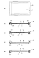
- 2A is a plan view of the positive electrode of the air battery shown in FIG. 1
- FIG. 2B is a cross-sectional view taken along line AA in FIG. 2A
- FIG. 2C is a plan view of the negative electrode.
- FIG. 3 is a cross-sectional view showing an assembled battery in which the air batteries shown in FIG. 1 are stacked.
- FIG. 4 is a cross-sectional view showing another example of the positive electrode in the air battery according to the present embodiment.
- FIG. 5A is a plan view showing another example of the positive electrode in the air battery according to this embodiment, and FIGS.
- FIG. 5B to 5E are cross-sectional views showing examples of the electrode fixing structure.
- 6A to 6D are cross-sectional views showing other examples of the positive electrode in the air battery according to the present embodiment
- FIG. 6E is a plan view showing the arrangement of the reinforcing material.
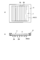
- FIG. 7A is a bottom view showing an example of the negative electrode in the air battery according to this embodiment
- FIG. 7B is a cross-sectional view of the negative electrode.
- FIG. 8 is a cross-sectional view showing an assembled battery formed by stacking air batteries using the negative electrode shown in FIG.
- FIG. 9A is a bottom view showing another example of the negative electrode in the air battery according to the present embodiment
- FIG. 9B is a cross-sectional view of the negative electrode.
- FIG. 10A is a bottom view showing another example of the negative electrode in the air battery according to the present embodiment
- FIG. 10B is a cross-sectional view of the negative electrode
- 11A is a bottom view showing another example of the negative electrode in the air battery according to the present embodiment
- FIG. 11B is a cross-sectional view of the negative electrode
- 12A is a bottom view showing another example of the negative electrode in the air battery according to the present embodiment
- FIG. 12B is a cross-sectional view of the negative electrode.
- FIG. 13 is a cross-sectional view showing another example of an assembled battery in which air batteries according to this embodiment are stacked.
- the air battery of this embodiment is a battery in which oxygen in the air is in contact with the positive electrode and the oxygen is used as the positive electrode active material.
- the air battery 10 has a rectangular plate shape.
- the air battery 10 includes a positive electrode 1 and a negative electrode 2 that are positive and negative electrodes, and outer frame members (31, 32) disposed on the outer peripheral portions of the positive electrode 1 and the negative electrode 2.
- the air battery 10 has the structure which joined the positive electrode 1 and the outer frame material at least.
- FIG. 1 shows a cross section based on the BB line of the positive electrode 1 shown in FIG. 2 (a) and a cross section based on the CC line of the negative electrode 2 shown in FIG. 2 (c).
- the outer frame member includes a first outer frame member 31 integrally joined to the positive electrode 1 and a second outer frame member 32 joined integrally to the negative electrode 2.
- the first outer frame member 31 and the second outer frame member 32 are hermetically bonded to each other by welding or the like, so that the electrolyte container 4 is formed between the positive electrode 1 and the negative electrode 2.
- pouring part provided with valves can be provided in any one or both of the 1st outer frame material 31 and the 2nd outer frame material 32. FIG. Thereby, the injection type air battery 10 is obtained.
- the first outer frame material 31 and the second outer frame material 32 have a thickness larger than the thickness of the electrodes (the positive electrode 1 and the negative electrode 2).
- the first outer frame member 31 joined to the positive electrode 1 is thin so that the upper and lower sides in FIG. 2A are flush with the positive electrode surface as shown in FIG. 2B. It has become.
- an in-plane direction (a direction along the surface) indicated by an arrow in FIG. 2 is formed on the surface side of the positive electrode 1. ) Air flow path F.
- the first outer frame member 31 and the second outer frame member 32 preferably have electrical insulation.
- the first outer frame member 31 and the second outer frame member 32 are preferably made of a resin having an electrolytic solution resistance such as polypropylene (PP) or engineering plastic, which can reduce the weight.
- PP polypropylene
- the first outer frame member 31 and the second outer frame member 32 use fiber reinforced plastic (FRP) in which a resin and a reinforcing fiber such as a carbon fiber or a glass fiber are combined in order to further increase the mechanical strength.
- FRP fiber reinforced plastic
- the positive electrode 1 is in contact with oxygen in the air and uses the oxygen as a positive electrode active material.
- the positive electrode 1 includes a catalyst layer 11 including a gas diffusion layer, and a water repellent layer 12 disposed on the surface of the positive electrode (the upper surface of the battery in FIG. 1).
- the catalyst layer 11 is formed of a conductive porous material.
- the catalyst layer 11 is formed by, for example, supporting a catalyst such as manganese dioxide inside a conductive porous body formed of a carbon material and a binder resin.
- the water repellent layer 12 is a member having liquid tightness with respect to the electrolytic solution and air permeability with respect to oxygen.
- the water repellent layer 12 uses a water repellent film such as a fluororesin so as to prevent the electrolyte from leaking to the outside.
- the water repellent layer 12 has a large number of fine holes so that oxygen can be supplied to the catalyst layer 11.
- the negative electrode 2 includes a negative electrode metal layer 21 containing a metal that functions as a negative electrode active material, and a negative electrode current collecting layer 22 disposed on the negative electrode surface (the battery lower surface in FIG. 1).
- the metal functioning as the negative electrode active material is preferably a pure metal selected from the group consisting of lithium (Li), aluminum (Al), iron (Fe), zinc (Zn), and magnesium (Mg).
- the metal functioning as the negative electrode active material is an alloy containing at least one selected from the group consisting of lithium (Li), aluminum (Al), iron (Fe), zinc (Zn), and magnesium (Mg). It is preferable.
- aluminum (Al) is used as the negative electrode metal layer 21.
- the negative electrode current collecting layer 22 is a conductive member made of a material that can prevent the electrolytic solution from leaking to the outside. As the negative electrode current collecting layer 22, it is preferable to use at least one material selected from the group consisting of stainless steel, copper, a copper alloy, and a metal material plated with corrosion-resistant metal.
- the negative electrode current collecting layer 22 is more preferably made of a material having higher electrolytic solution resistance than the negative electrode metal layer 21. In the present embodiment, a copper foil is used as the negative electrode current collecting layer 22.
- the electrolyte solution interposed between the positive electrode 1 and the negative electrode 2 is preferably an aqueous solution or a non-aqueous electrolyte mainly composed of potassium hydroxide (KOH) or chloride. Note that the electrolytic solution can be replaced with a solid or gel electrolyte.
- the first outer frame member 31 and the second outer frame member 32 are made of resin, and are integrated with the outer peripheral portion of the electrodes (the positive electrode 1 and the negative electrode 2) by, for example, injection molding or the like. Molded. Thereby, the positive electrode 1 and the negative electrode 2 are integrated with each outer frame material (31, 32) in a state where the entire outer peripheral portion is embedded in the resin. With such a configuration, it is possible to improve the mechanical strength of the electrode and the sealing performance against the electrolytic solution.
- the first outer frame member 31 in the air battery 10 of the present embodiment is integrally joined to the outer peripheral portion of the positive electrode 1, and the electrolytic solution is joined from the joint portion between the positive electrode 1 and the first outer frame member 31. It is the composition which prevents the leak of.
- the outer peripheral part of the positive electrode 1 and the first outer frame member 31 may be joined using an adhesive.
- the outer peripheral part of the positive electrode 1 may be joined by being buried in the first outer frame member 31.
- a part of the outer peripheral part of the positive electrode 1 and the first outer frame member 31 are joined using an adhesive, and the other part of the outer peripheral part of the positive electrode 1 is joined by being buried in the first outer frame member 31. It may be.
- the outer peripheral portion of the positive electrode 1 is supported by the first outer frame member 31, and the strength of the positive electrode 1 can be increased. Furthermore, since the outer peripheral portion of the positive electrode 1 is joined to the first outer frame member 31, it is possible to suppress leakage of the electrolytic solution.
- the outer periphery of the positive electrode 1 needs to be integrally joined with the outer frame material.
- the entire outer periphery of the positive electrode 1 is integrally joined to the outer frame material.
- joining of the outer peripheral part of the positive electrode 1 and an outer frame material is not limited to an adhesive agent or burying, For example, you may join by welding.
- the second outer frame member 32 in the air battery 10 of the present embodiment is integrally joined to the outer peripheral portion of the negative electrode 2, and the electrolyte solution leaks from the joint portion between the negative electrode 2 and the second outer frame member 32. It is the structure which prevents.
- the outer peripheral portion of the negative electrode 2 and the second outer frame member 32 may be bonded using an adhesive.
- the outer peripheral part of the negative electrode 2 may be joined by being buried in the second outer frame member 32.
- a part of the outer peripheral part of the negative electrode 2 and the second outer frame member 32 are joined using an adhesive, and another part of the outer peripheral part of the negative electrode 2 is joined by being buried in the second outer frame member 32. It may be.
- the outer peripheral portion of the negative electrode 2 is supported by the second outer frame member 32, and the strength of the negative electrode 2 can be increased. Furthermore, since the outer peripheral part of the negative electrode 2 is joined to the second outer frame member 32, it is possible to suppress leakage of the electrolytic solution.
- the outer peripheral portion of the negative electrode 2 is integrally joined with the outer frame material.
- the entire outer peripheral portion of the negative electrode 2 is integrally joined to the outer frame material.
- joining of the outer peripheral part of the negative electrode 2 and an outer frame material is not limited to an adhesive or burying, For example, you may join by welding.
- the negative electrode 2 includes the negative electrode metal layer 21 made of aluminum and the negative electrode current collector layer 22 made of copper foil, which is a material having higher electrolytic solution resistance than the negative electrode metal layer 21. ing. It is preferable that at least the negative electrode current collecting layer 22 and the second outer frame member 32 of the negative electrode metal layer 21 and the negative electrode current collecting layer 22 are integrated. In FIG. 1 and FIG. 2C, both the negative electrode metal layer 21 and the negative electrode current collecting layer 22 are integrated with the second outer frame member 32. That is, the outer peripheral portions of both the negative electrode metal layer 21 and the negative electrode current collecting layer 22 are buried in the second outer frame member 32.
- the negative electrode metal layer 21 and the negative electrode current collecting layer 22 are integrated. That is, the negative electrode metal layer 21 and the negative electrode current collecting layer 22 are laminated and joined to each other. Moreover, as shown in FIGS. 1 and 2C, the negative electrode current collecting layer 22 has a size having an outer peripheral portion outside the negative electrode metal layer 21 in a plan view.
- the air battery 10 having the above configuration has a small number of parts, has a very simple structure, and is thin.
- a contact member is provided on the outer frame member (31, 32), or a conductive member is inserted between adjacent air cells 10, thereby wiring. It is possible to connect them in series without using a kind.
- the assembled battery in which the air battery 10 is stacked is very suitable as a power source mounted on a vehicle such as an automobile.
- the air cell 10 has integrally joined at least the positive electrode 1 and the first outer frame member 31 of the two electrodes, the positive electrode 1 is reinforced with the first outer frame member 31, The mechanical strength and the sealing performance against the electrolyte can be improved. Thereby, the thickness of the air battery can be further reduced. Furthermore, since the internal resistance also decreases with the reduction in thickness, the output of the air battery 10 can be increased.
- the positive electrode 1 may bend and stress concentration may occur in the outer periphery.
- the air battery 10 since the air battery 10 has high mechanical strength and high sealing performance, it is possible to eliminate the possibility that the sealing performance of the electrolytic solution is impaired as the positive electrode 1 is deformed.
- the first outer frame member 31 and the second outer frame member 32 are made of resin, and are integrally formed on the outer periphery of the positive and negative electrodes (1, 2). Therefore, even if it is thin, sufficient strength can be ensured, the sealing performance against the electrolytic solution is further enhanced, and the productivity is excellent.
- the air battery 10 at least the negative electrode current collecting layer 22 and the second outer frame member 32 of the negative electrode metal layer 21 and the negative electrode current collecting layer 22 constituting the negative electrode 2 are integrated.
- the air battery 10 can maintain the sealing property with respect to electrolyte solution favorably by the negative electrode current collection layer 22, even when the negative electrode metal layer 21 is consumed with power generation.
- the air battery 10 is made of a material for the negative electrode current collecting layer 22 that has higher electrolytic solution resistance than the negative electrode metal layer 21, the sealing performance against the electrolytic solution is further enhanced.
- the material of the negative electrode current collecting layer 22 can be used even if it does not necessarily have higher electrolyte solution resistance than the negative electrode metal layer 21. That is, in the air battery 10, the power generation time and the consumption amount of the negative electrode metal layer 21 are known in advance, and the negative electrode current collecting layer 22 may be any one that can prevent leakage of the electrolytic solution after the end of power generation. Therefore, if the thickness is appropriately selected, the negative electrode current collecting layer 22 and the negative electrode metal layer 21 may be made of the same material. However, the use of the negative electrode current collecting layer 22 made of a material having higher electrolytic solution resistance than that of the negative electrode metal layer 21 makes it possible to provide a more secure air battery with improved sealing performance against the electrolytic solution. Become.
- the air battery 10 has a negative electrode metal layer 21 and a negative electrode current collecting layer 22 integrated in the negative electrode 2. Therefore, the negative electrode metal layer 21 and the negative electrode current collecting layer 22 are in a state of reinforcing each other, the contact resistance between them is reduced, and the negative electrode 2 which is thin and high in strength and has little current collection loss can be obtained. .
- the air battery 10 has such a size that the negative electrode current collecting layer 22 has an outer peripheral portion outside the negative electrode metal layer 21 in a plan view. That is, since the negative electrode current collecting layer 22 sufficiently covers the entire negative electrode metal layer 21, it is possible to further improve the sealing performance against the electrolytic solution. Moreover, since the part buried in the inside of the 2nd outer frame material 32 increases in the outer peripheral part of the negative electrode current collection layer 22, it becomes possible to suppress the leakage of electrolyte solution more.
- the outer peripheral portion of the positive electrode 1 is embedded in the first outer frame member 31 made of resin, whereas in this embodiment, the outer peripheral portion of the positive electrode 1 is partially attached to the first outer frame member 31. It is assembled and joined by adhesion or welding. Even in the air battery including the positive electrode 1, the mechanical strength of the positive electrode 1 and the sealing performance against the electrolytic solution can be improved as in the above-described embodiment, and the air battery can contribute to thinning and high output. It will be a thing.
- the positive electrode 1 of the air battery shown in FIG. 5 has an electrode fixing structure in which the first outer frame member 31 mechanically fixes the positive electrode 1 at least partially.
- a reinforcing layer 5 is provided between the water repellent layer 12 and the catalyst layer 11 of the positive electrode 1. That is, in the air battery of the present embodiment, the first outer frame member 31 and the second outer frame member 32 include an electrode fixing structure that mechanically fixes the electrodes (1, 2) at least partially.
- at least the positive electrode 1 can include the reinforcing layer 5.
- the reinforcing layer 5 is a member having conductivity and air permeability.
- a porous metal plate such as punching metal or a metal mesh, or a porous resin plate or resin mesh formed with a metal film such as plating can be used.
- a predetermined function can be obtained if the electrode fixing structure is provided in at least four corners of the rectangular positive electrode 1 shown in FIG. That is, in a thin air battery, the central portion of the positive electrode 1 bends during stacking, and stress concentration occurs at the four corners of the outer peripheral portion, particularly when the positive electrode 1 is rectangular. Therefore, the electrode fixing structure is preferably provided at least at the four corners of the first outer frame member 31, and more preferably provided over the entire circumference. Specific examples of the electrode fixing structure are shown in FIGS.
- the first outer frame member 31 is divided into an upper member 31A and a lower member 31B. Furthermore, a concave portion 31C and a convex portion 31D that can be engaged with each other are relatively provided on the opposing surfaces of the upper member 31A and the lower member 31B.
- the outer peripheral portion of the positive electrode 1 is sandwiched between the upper member 31A and the lower member 31B, the concave portion 31C and the convex portion 31D are engaged with each other, and the upper member 31A and the lower member 31B are bonded. Join by etc. Thereby, the positive electrode 1 and the 1st outer frame material 31 are integrally joined and fixed.
- the first outer frame member 31 is divided into an outer member 31E having a bowl-shaped cross section and an inner member 31F accommodated therein. Further, a bent portion 1 ⁇ / b> A is provided on the outer peripheral portion of the positive electrode 1.
- the bent portion 1A of the positive electrode 1 is sandwiched between the outer member 31E and the inner member 31F, and the outer member 31E and the inner member 31F are joined by bonding or the like. Thereby, the positive electrode 1 and the 1st outer frame material 31 are integrally joined and fixed.
- the electrode fixing structure shown in FIG. 5D is a configuration in which engaging portions 31G such as irregularities, holes, and protrusions that can be engaged with each other are provided on the outer peripheral portion of the positive electrode 1 and the first outer frame member 31.
- engaging portions 31G such as irregularities, holes, and protrusions that can be engaged with each other are provided on the outer peripheral portion of the positive electrode 1 and the first outer frame member 31.
- the positive electrode 1 and the first outer frame member 31 are engaged with each other by an engaging portion 31G, and both are bonded together by adhesion or the like. Thereby, the positive electrode 1 and the 1st outer frame material 31 are integrally joined and fixed.
- a bent portion 1 A is provided on the outer peripheral portion of the positive electrode 1, and a first outer frame material 31 made of resin is integrally formed on the outer peripheral portion of the positive electrode 1.
- the bent portion 1A of the positive electrode 1 is embedded in the resin, and the positive electrode 1 and the first outer frame member 31 are integrally joined and fixed.
- the air battery having the above electrode fixing structure can obtain the same operations and effects as the above embodiment. Further, the positive electrode 1 and the first outer frame member 31 are mechanically connected and then both are integrated. Therefore, even if it is thin, sufficient mechanical strength and sealing performance against the electrolytic solution can be improved.
- the electrode fixing structure a suitable one can be selected according to the manufacturing process of the electrode.
- the air battery including the positive electrode 1 of the present embodiment has higher mechanical strength due to the reinforcing layer 5.
- the deflection of the positive electrode 1 at the time of lamination can be suppressed, stress concentration can be relieved greatly, and the air battery can be further reduced in thickness, increased in output and reduced in weight.
- the reinforcing layer 5 functions as a current collector and it is possible to realize a reduction in internal resistance.
- the above-described electrode fixing structure can naturally be employed for joining the negative electrode 2 and the second outer frame member 32.
- the mechanical strength and the sealing performance against the electrolytic solution are improved as in the case of the positive electrode side, so that it can contribute to the performance enhancement of the air battery in combination with the configuration of the positive electrode 1.
- the positive electrode 1 shown in FIG. 6A includes a water repellent layer 12, a reinforcing layer 5, and a catalyst layer 11 in order from the positive electrode surface.
- the outer peripheral portions of the water repellent layer 12 and the reinforcing layer 5 are integrated with the first outer frame member 31, and the catalyst layer 11 is provided on the lower surface of the reinforcing layer 5.
- the positive electrode 1 shown in FIG. 6B includes a water-repellent layer 12, a catalyst layer 11, and a reinforcing layer 5 in order from the positive electrode surface.
- the outer peripheral portion of the water repellent layer 12 is integrated with the first outer frame member 31, and the catalyst layer 11 and the reinforcing layer 5 are provided on the lower surface of the water repellent layer 12.
- a positive electrode 1 shown in FIG. 6C includes a water repellent layer 12, a reinforcing layer 5, and a catalyst layer 11 in order from the positive electrode surface.
- the outer peripheral portion of the reinforcing layer 5 is integrated with the first outer frame member 31, the water repellent layer 12 is provided on the upper surface of the reinforcing layer 5, and the catalyst layer 11 is provided on the lower surface of the reinforcing layer 5. is there.
- the positive electrode 1 shown in FIG. 6D includes a water repellent layer 12, a reinforcing layer 5, and a catalyst layer 11 in order from the positive electrode surface.
- the positive electrode 1 is obtained by integrating the outer peripheral portions of all layers and the first outer frame material 31.
- the reinforcing layer 5 is preferably formed of a breathable member such as a perforated plate or a mesh.
- a breathable member such as a perforated plate or a mesh.
- the reinforcement layer 5 can improve the adhesiveness to the adjacent water-repellent layer 12 or the catalyst layer 11 by using 5 A of frame parts as an adhesive allowance. Further, by bonding the frame portion 5A and the first outer frame material 31, both adhesion and sealing properties can be enhanced.
- the mechanical strength and the sealing performance against the electrolytic solution can be remarkably improved as in the above embodiment. Furthermore, the contact resistance among the water repellent layer 12, the catalyst layer 11 and the reinforcing layer 5 can be further reduced, which can contribute to further thinning, high output and light weight of the air battery.
- the negative electrode 2 of the air battery shown in FIG. 7 has a negative electrode current collecting layer 22 that forms an air flow path F on the surface of the positive electrode 1 of the adjacent air battery when a plurality of air batteries are connected in series. 26A.
- the second outer frame member 32 is integrated with the outer periphery of the negative electrode metal layer 21 and the negative electrode current collecting member 26 ⁇ / b> A.
- the negative electrode current collecting member 26A has a plurality of protrusions 26a protruding on the lower surface thereof arranged in parallel at predetermined intervals. In FIG. 7, four protrusions 26a are arranged in parallel at a predetermined interval on the lower surface of the negative electrode current collecting member 26A. These protrusions 26a are formed along the air flow direction shown in FIG. Such a negative electrode current collecting member 26A is obtained by pressing a metal plate, and the opposite surface of the protrusion 26a has a groove shape.
- the negative electrode 2 includes the second outer frame member 32 integrated with the negative electrode 2 and the first outer frame member 31 integrated with the positive electrode 1 in an airtight manner to form the air battery 10. To do.
- an electrolytic solution container 4 is formed between the positive electrode 1 and the negative electrode 2.
- the assembled battery 100 is comprised by laminating a plurality of air batteries 10.
- the protrusion 26a of the negative electrode current collecting member 26A of the negative electrode 2 adjacent to the upper side of the positive electrode 1 of the air battery 10 is in contact with the positive electrode 1, and the air with respect to the positive electrode 1 is interposed between the protrusions 26a.
- a flow path F is formed. Accordingly, the negative electrode current collecting member 26A functions as a spacer and a connector between the positive electrode 1 and the negative electrode 2 adjacent to each other.
- the negative electrode current collecting layer 22 forms an air flow path F on the surface of the positive electrode 1 of the adjacent air battery. 26B.
- the negative electrode 2 has integrated the 2nd outer frame material 32 in the outer peripheral part of the negative electrode metal layer 21 and the negative electrode current collection member 26B.
- the negative electrode current collecting member 26B of this embodiment has a wavy cross section. Even in the negative electrode 2 including the negative electrode current collecting member 26B, the negative electrode current collecting member 26B forms an air flow path F for the positive electrode 1 and functions as a spacer and a connector, as in the above embodiment.
- the negative electrode current collecting layer 22 forms an air flow path F on the surface of the positive electrode 1 of the adjacent air battery. 26C.
- the second outer frame member 32 is integrated with the outer periphery of the negative electrode metal layer 21 and the negative electrode current collector 26 ⁇ / b> C.
- the negative electrode current collecting member 26C of this embodiment is formed by arranging a plurality of protrusions 26b protruding in the vertical and horizontal directions. Even in the negative electrode 2 including the negative electrode current collecting member 26C, the negative electrode current collecting member 26C forms an air flow path F with respect to the positive electrode 1 and functions as a spacer and a connector as in the above embodiment.
- the negative electrode current collecting layer 22 forms an air flow path F on the surface of the positive electrode 1 of the adjacent air battery. 26D.
- the negative electrode 2 has integrated the 2nd outer frame material 32 in the outer peripheral part of the negative electrode metal layer 21 and the negative electrode current collection member 26D.
- the negative electrode current collecting member 26D of this embodiment is formed by integrally forming a plurality of protrusions protruding downward on the negative electrode current collecting layer 22.
- the negative electrode current collector 26D includes a planar main body portion 26c that is bonded to the negative electrode metal layer 21, and a plurality of rib-shaped protrusion portions 26d that protrude from the main body portion 26c. In FIG. 11, seven rib-shaped protrusions 26d are provided. These rib-shaped protrusions 26d are arranged in parallel at a predetermined interval.
- the negative electrode current collecting member 26D forms an air flow path with respect to the positive electrode 1 and functions as a spacer and a connector as in the above embodiment.
- the negative electrode 2 of the air battery shown in FIG. 12 includes a negative electrode current collecting member 26E that forms an air flow path F on the surface of the positive electrode 1 of the adjacent air battery.
- the negative electrode current collecting member 26E includes a planar main body portion 26c joined to the negative electrode metal layer 21, and a plurality of (seven in the illustrated example) rib shapes protruding from the main body portion 26c. A protrusion 26d is provided.
- the negative electrode current collection member 26E is provided with the support layer 27 joined to the main-body part 26c in the state which penetrated each rib-shaped protrusion 26d.
- the negative current collector 26E forms an air flow path F with respect to the positive electrode 1 and functions as a spacer and a connector, as in the above embodiment. .
- the main body portion 26c of the negative electrode 2 is reinforced by the support layer 27, the main body portion 26c is further reduced in thickness and weight, and further, bending of the negative electrode 2 when the negative electrode metal layer 21 is consumed is suppressed. can do.
- the negative electrode 2 of the air battery shown in FIGS. 7 to 12 employs a negative electrode current collecting member (23A, 26B, 26C, 26D, 26E) three-dimensionally formed in the thickness direction in order to obtain the air flow path F.
- the mechanical strength can also be increased by the shape of the current collecting member itself.
- the air flow path F is indispensable between the adjacent air cells 10, even if a negative electrode current collecting member that is three-dimensionally formed in the thickness direction is used, there is no concern that the air cell 10 may be thinned. No.
- the air cells 10 can be electrically connected to each other without using wirings. Thereby, reduction of internal resistance and reduction of the number of parts can be realized, and high output and low cost of the air battery 10 and the assembled battery 100 can be achieved.
- the air flow path F is formed between the protrusions 26a or at the lower trough portion of the wave shape. If a large number of holes are formed in the ridge 26a and the lower crest of the corrugated shape, the groove-like portion on the back side of the ridge 26a and the trough on the upper side of the corrugated shape are also used as the air flow path F. Can do.
- the air battery 10 shown in FIG. 13 has a configuration in which the positive electrode 1 has conductivity on the surface thereof.
- the illustrated positive electrode 1 includes a positive electrode current collecting layer 16 on the upper side of a water repellent layer 12, and the positive electrode current collecting layer 16 ensures conductivity on the positive electrode surface.
- the positive electrode current collecting layer 16 has air permeability in order to supply air to the water repellent layer 12.
- the positive electrode current collecting layer 16 is made of a porous metal plate such as punching metal, a metal mesh, a porous resin plate or a resin mesh formed with a metal film such as plating on the surface of the positive electrode current collecting layer 16, etc. Can be used.
- a plurality of air cells 10 are stacked to form an assembled battery 100, and an air flow path F is formed between adjacent air cells 10.
- the positive electrode current collecting layer 16 contacts the adjacent negative electrode 2 and functions as a spacer and a connector.
- the positive electrode current collecting layer 16 may be integrated with the first outer frame member 31.
- the air battery 10 of this embodiment contains what has electroconductivity on the surface of the positive electrode 1.
- FIG. Therefore, the positive electrode 1 has a structure including the positive electrode current collecting layer 16 described above, and in the assembled battery 100 as shown in FIG. 8, the water repellent layer 12 has conductivity.
- At least the mechanical strength of the positive electrode and the sealing property against the electrolytic solution can be improved, and it can contribute to a reduction in thickness suitable for in-vehicle use.
Landscapes
- Chemical & Material Sciences (AREA)
- Chemical Kinetics & Catalysis (AREA)
- Electrochemistry (AREA)
- General Chemical & Material Sciences (AREA)
- Engineering & Computer Science (AREA)
- Manufacturing & Machinery (AREA)
- Hybrid Cells (AREA)
- Battery Mounting, Suspending (AREA)
- Inert Electrodes (AREA)
Abstract
本発明に係る空気電池(10)は、正極(1)及び負極(2)と、正極及び負極の外周部に配置した外枠材(31,32)とを備える。そして、正極と外枠材とが一体的に接合してある。さらに、本発明に係る組電池(100)は、空気電池を複数備え、複数の空気電池が積層されている。この構成により、正極の機械的強度と電解液に対するシール性を高めることができる。さらに、空気電池全体を薄型化することができ、車載用として好適な組電池とすることができる。
Description
本発明は、酸素を正極活物質として利用する空気電池に関し、特に複数個を積層して組電池を構成するのに好適な空気電池に関する。
従来の空気電池としては、例えば特許文献1に記載されたものがある。特許文献1に記載の空気電池は、複数の部材から成る扁平な電槽と、電槽の正面及び背面に配置した空気陰極(正極)と、電槽に収容される陽極(金属負極)とを備えている。空気陰極は、電槽に対して着脱可能であって、電槽に設けたゴムガスケット等に押し付けてシールする構造である。他方、陽極は、同様に着脱可能であって、電槽の側部から差し込んで空気陰極と同様にシールする構造である。つまり、空気陰極及び陽極は、交換する都合上、ゴムガスケット等に押し付けてシール性を確保している。
近年、自動車等の車両の電源又は補助電源として使用する空気電池の研究開発が進められている。車載用の空気電池は、車両に要求される出力及び容量、狭いスペースへの搭載性などを考慮すると、構造を簡単にして薄型にし、複数個を直列に接続して組電池を構成し得るものにする必要がある。ところが、特許文献1の空気電池は、互いに直接接続することができない構造であり、さらに部品点数が多くて構造も複雑であることから、車載用には不適当であった。
また、この種の空気電池では正極を薄い通気性材料で形成しているので、金属製の負極に比べて正極の機械的強度が低い。このため、空気電池の構造の簡略化や薄型化を行った場合、積層時に正極が撓み、正極の外周部に応力集中が生じることが予想される。また、従来の空気電池のようにゴムガスケット等に押し付けてシール性を確保する構造では、正極の変形に伴って電解液に対するシール性が低下する恐れがある。
本発明は、このような従来技術の有する課題に鑑みてなされたものである。そして、その目的は、正負の電極のうちの少なくとも正極の機械的強度と電解液に対するシール性とを高めることができ、車載用として好適な薄型の空気電池を提供することにある。
本発明の態様に係る空気電池は、正極及び負極と、正極及び負極の外周部に配置した外枠材とを備える。そして、前記正極と外枠材とが一体的に接合してあることを要旨とする。
以下、本発明の実施形態に係る空気電池について、図面に基づき詳細に説明する。なお図面の寸法比率は説明の都合上誇張されており、実際の比率とは異なる場合がある。
本実施形態の空気電池は、空気中の酸素が正極と接触し、当該酸素を正極活物質として使用する電池である。そして、図1及び図2に示すように、空気電池10は、矩形板状を成すものである。さらに、空気電池10は、正負の電極である正極1及び負極2と、正極1及び負極2の外周部に配置した外枠材(31,32)を備えている。そして、空気電池10は、少なくとも正極1と外枠材とを接合した構成を有している。なお、図1では、図2(a)に示す正極1のB-B線に基づく断面と、図2(c)に示す負極2のC-C線に基づく断面とを示している。
本実施形態では、外枠材として、正極1を一体的に接合した第1外枠材31と、負極2を一体的に接合した第2外枠材32とを備えている。そして、第1外枠材31及び第2外枠材32同士を溶着等により気密的に接合することにより、正極1と負極2との間に電解液の収容部4を形成している。なお、図示は省略したが、第1外枠材31及び第2外枠材32のいずれか一方又は両方には、バルブ類を備えた電解液注入部を設けることができる。これにより、注液式の空気電池10となる。
第1外枠材31及び第2外枠材32は、電極(正極1及び負極2)の厚さよりも大きい厚さを有している。特に、正極1と接合した第1外枠材31は、図2(a)中における上下の辺部分が、図2(b)に示すように、正極表面と同一面状を成すように薄肉になっている。これにより、図3に示すように、空気電池10を複数個積層して組電池100を構成した際に、正極1の表面側に、図2中の矢印で示す面内方向(面に沿う方向)の空気流路Fを形成する。
また、第1外枠材31及び第2外枠材32は、電気絶縁性を有することが好ましい。例えば、第1外枠材31及び第2外枠材32は、ポリプロピレン(PP)やエンジニアリングプラスチックなどの耐電解液性を有する樹脂製であることが好ましく、これにより軽量化を図ることもできる。さらに、第1外枠材31及び第2外枠材32は、機械的強度をより高めるために、樹脂とカーボン繊維やガラス繊維等の強化繊維とを複合化した繊維強化プラスチック(FRP)を用いることもできる。
正極1は空気中の酸素と接触し、当該酸素を正極活物質として使用するものである。具体的には、正極1は、ガス拡散層を含む触媒層11と、正極表面(図1中では電池上面)に配置した撥水層12とを備えている。触媒層11は、導電性の多孔質材料で形成されている。具体的には、触媒層11は、例えばカーボン材料とバインダー樹脂とで形成した導電性多孔体の内部に、二酸化マンガンなどの触媒を担持させたものである。
撥水層12は、電解液に対して液密性を有し、かつ、酸素に対して通気性を有する部材である。この撥水層12は、電解液が外部へ漏出するのを阻止し得るように、フッ素樹脂などの撥水膜を用いている。一方、撥水層12は、触媒層11に酸素を供給し得るように多数の微細孔を有している。
負極2は、負極活物質として機能する金属を含有する負極金属層21と、負極表面(図1中では電池下面)に配置した負極集電層22を備えている。負極活物質として機能する金属は、リチウム(Li)、アルミニウム(Al)、鉄(Fe)、亜鉛(Zn)及びマグネシウム(Mg)からなる群から選ばれる純金属であることが好ましい。また、負極活物質として機能する金属は、リチウム(Li)、アルミニウム(Al)、鉄(Fe)、亜鉛(Zn)及びマグネシウム(Mg)からなる群から選ばれる少なくとも一つを含有する合金であることが好ましい。本実施形態では、負極金属層21としてアルミニウム(Al)を用いている。
負極集電層22は、電解液が外部に漏出することを阻止し得る材質から成る導電部材である。負極集電層22としては、ステンレス、銅、銅合金、及び金属材料の表面に耐食性を有する金属をメッキした材料からなる群より選ばれる少なくとも一つの材料を用いることが好ましい。負極集電層22は、負極金属層21よりも耐電解液性の高い材料から成るものであることがより好ましい。本実施形態では、負極集電層22として銅箔を用いている。
正極1と負極2との間に介在する電解液は、水酸化カリウム(KOH)や塩化物を主成分とした水溶液又は非水電解液であることが好ましい。なお、当該電解液は、固体あるいはゲル状の電解質に置換することも可能である。
ここで、本実施形態の空気電池10は、第1外枠材31及び第2外枠材32が樹脂製であり、例えば射出形成などにより、電極(正極1、負極2)の外周部に一体成形してある。これにより、正極1及び負極2は、その外周部全体が樹脂中に埋設された状態で、各々の外枠材(31,32)と一体化している。このような構成により、電極の機械的強度と電解液に対するシール性とを高めることが可能となる。
より詳細に説明すると、本実施形態の空気電池10における第1外枠材31は、正極1の外周部と一体的に接合され、正極1と第1外枠材31との接合部より電解液の漏れを防止する構成となっている。具体的には、正極1の外周部と第1外枠材31とが接着剤を用いて接合されていてもよい。さらに、正極1の外周部を第1外枠材31に埋没させることで接合されていてもよい。また、正極1の外周部の一部分と第1外枠材31とが接着剤を用いて接合され、さらに正極1の外周部の他の部分を第1外枠材31に埋没させることで接合されていてもよい。このような構成により、正極1の外周部が第1外枠材31に支持され、正極1の強度を高めることが可能となる。さらに、正極1の外周部が第1外枠材31に接合されることで、電解液の漏出も抑制することが可能となる。
なお、本実施形態の空気電池10では、正極1の外周部の少なくとも一部が外枠材と一体的に接合されている必要がある。ただ、電解液の漏れを防止するという観点から、正極1の外周部の全体が外枠材と一体的に接合されていることが好ましい。また、正極1の外周部と外枠材との接合は、接着剤や埋没させることに限定されず、例えば溶着により接合してもよい。
同様に、本実施形態の空気電池10における第2外枠材32は、負極2の外周部と一体的に接合され、負極2と第2外枠材32との接合部より電解液の漏れを防止する構成となっている。具体的には、負極2の外周部と第2外枠材32とが接着剤を用いて接合されていてもよい。さらに、負極2の外周部を第2外枠材32に埋没させることで接合されていてもよい。また、負極2の外周部の一部分と第2外枠材32とが接着剤を用いて接合され、さらに負極2の外周部の他の部分を第2外枠材32に埋没させることで接合されていてもよい。このような構成により、負極2の外周部が第2外枠材32に支持され、負極2の強度を高めることが可能となる。さらに、負極2の外周部が第2外枠材32に接合されることで、電解液の漏出も抑制することが可能となる。
なお、本実施形態の空気電池10では、負極2の外周部の少なくとも一部が外枠材と一体的に接合されていることが好ましい。ただ、電解液の漏れを防止するという観点から、負極2の外周部の全体が外枠材と一体的に接合されていることがより好ましい。また、負極2の外周部と外枠材との接合は、接着剤や埋没させることに限定されず、例えば溶着により接合してもよい。
空気電池10は、上述したように、負極2が、アルミニウム製の負極金属層21と、負極金属層21よりも耐電解液性の高い材料である銅箔製の負極集電層22とを備えている。そして、負極金属層21及び負極集電層22のうちの少なくとも負極集電層22と第2外枠材32とが一体化されていることが好ましい。なお、図1及び図2(c)では、負極金属層21及び負極集電層22の両方が第2外枠材32と一体化されている。つまり、負極金属層21及び負極集電層22の両方の外周部が第2外枠材32に埋没している。
さらに、空気電池10は、負極金属層21と負極集電層22とが一体化されている。つまり、負極金属層21と負極集電層22とが積層され、互いに接合されている。しかも、図1及び図2(c)に示すように、負極集電層22が、平面視において、負極金属層21の外側に外周部を有する大きさになっている。
上記構成を備えた空気電池10は、部品点数が少なく、構造が極めて簡単で薄型なものとなる。そして、空気電池10を複数個積層した場合には、例えば、外枠材(31,32)に接点部材を設けたり、隣接する空気電池10の間に導電部材を挿入したりすることで、配線類を用いることなく、互いに直列接続することが可能となる。その結果、空気電池10を積層した組電池は、自動車等の車両に搭載する電源として非常に好適なものとなる。
そして、空気電池10は、両電極のうちの少なくとも正極1と第1外枠材31とが一体的に接合してあるので、正極1が第1外枠材31で補強された状態になり、機械的強度と電解液に対するシール性を高めることができる。これにより、空気電池の更なる薄型化を図ることができる。さらに、この薄型化に伴って内部抵抗も減少することから、空気電池10の高出力化を図ることもできる。
また、空気電池10を複数個積層した際には、正極1が撓んで外周部に応力集中が生じることがある。しかし、上述のように、空気電池10は機械的強度及びシール性が高いので、正極1の変形に伴って電解液のシール性が損なわれるような恐れを解消することができる。
図1に示す空気電池10では、正極1と第1外枠材31だけでなく、負極2と第2外枠材32も一体的に接合してある。これにより、負極2の機械的強度や電解液に対するシール性が高められる。その結果、負極2及び第2外枠材32と正極1及び第1外枠材31と組み合わせることで、空気電池10の更なる薄型化及び高出力化に貢献することができる。
また、空気電池10は、第1外枠材31及び第2外枠材32が樹脂製であり、正負の電極(1,2)の外周部に一体成形してある。そのため、薄くても十分な強度を確保し得ると共に、電解液に対するシール性がより一層高くなり、生産性に優れている。
さらに空気電池10は、負極2を構成する負極金属層21及び負極集電層22のうちの少なくとも負極集電層22と第2外枠材32とが一体化してある。これにより、空気電池10は、発電に伴って負極金属層21が消耗した場合でも、負極集電層22により電解液に対するシール性を良好に維持することができる。さらに、空気電池10は、負極集電層22の材料が負極金属層21よりも耐電解液性の高いものであるから、電解液に対するシール性がより一層高められる。
なお、負極集電層22の材料は、必ずしも負極金属層21よりも耐電解液性が高いものでなくても使用可能である。つまり、空気電池10では発電時間や負極金属層21の消耗量が予め分かっており、負極集電層22が発電終了後に電解液の漏出を阻止し得るものであればよい。そのため、厚さなどを適宜選択すれば、負極集電層22と負極金属層21とが同一材料である場合も有り得る。しかし、負極金属層21よりも耐電解液性が高い材料から成る負極集電層22を用いれば、電解液に対するシール性がより確実になり、安全性の高い空気電池を提供することが可能となる。
さらに空気電池10は、負極2において、負極金属層21と負極集電層22とを一体化している。そのため、負極金属層21及び負極集電層22が互いに補強し合う状態になると共に、双方間の接触抵抗も低減され、薄くて強度が高いうえに集電ロスの少ない負極2を得ることができる。
空気電池10は、負極集電層22が、平面視において負極金属層21の外側に外周部を有する大きさである。つまり、負極集電層22が負極金属層21の全体を十分に覆っているので、電解液に対するシール性の更なる向上を実現することができる。また、負極集電層22の外周部において、第2外枠材32の内部に埋没する部分が増加することから、電解液の漏れをより抑制することが可能となる。
図4乃至図13では、本実施形態の空気電池の更に他の例を示す。なお、以下の各実施形態において、上記の実施形態と同一の構成部位は同一の符号を付して、詳細な説明を省略する。
図4に示す空気電池の正極1は、第1外枠材31と一体的に接合してある。上記の実施形態では、樹脂製の第1外枠材31に正極1の外周部を埋設したのに対して、この実施形態では、第1外枠材31の一部に正極1の外周部を組み込んで、接着や溶着などにより接合したものである。この正極1を備えた空気電池にあっても、上記の実施形態と同様に、正極1の機械的強度及び電解液に対するシール性が高められ、空気電池の薄型化や高出力化に貢献し得るものとなる。
図5に示す空気電池の正極1は、第1外枠材31が、少なくとも一部に、正極1を機械的に固定する電極固定構造を備えている。また、正極1の撥水層12と触媒層11との間に、補強層5を備えている。すなわち、本実施形態の空気電池は、第1外枠材31及び第2外枠材32が、少なくとも一部に、電極(1,2)を機械的に固定する電極固定構造を備えている構成とし、また、少なくとも正極1が、補強層5を備えている構成とすることができる。
補強層5は、導電性及び通気性を有する部材である。そして、補強層5としては、例えば、パンチングメタルなどの多孔金属板や金属メッシュ、若しくは多孔樹脂板や樹脂メッシュの表面にめっき等の金属被膜を形成したものを用いることができる。
電極固定構造は、図5(a)に示す矩形形状の正極1において、少なくとも四隅に設ければ所定の機能を得ることができる。つまり、薄型の空気電池では、積層時において正極1の中央部が撓むので、特に正極1が矩形状である場合には、外周部の四隅に応力集中が生じる。そこで、電極固定構造は、少なくとも第1外枠材31の四隅に設けるのが好ましく、全周に渡って設けることがより好ましい。電極固定構造の具体例を図5(b)~(e)に示す。
図5(b)に示す電極固定構造は、第1外枠材31が上側部材31Aと下側部材31Bとに分割してある。さらに、上側部材31A及び下側部材31Bの相対する面に、互いに係合可能な凹部31C及び凸部31Dを相対的に設けている。この電極固定構造は、上側部材31Aと下側部材31Bとの間に正極1の外周部を挟み込んで、凹部31C及び凸部31Dを互いに係合して、上側部材31Aと下側部材31Bを接着等により接合する。これにより、正極1と第1外枠材31とを一体的に接合して固定する。
図5(c)に示す電極固定構造は、第1外枠材31が、断面が鉤状の外側部材31Eと、その内側に収容される内側部材31Fとに分割してある。さらに、正極1の外周部に折曲部1Aを設けている。この電極固定構造は、外側部材31Eと内側部材31Fとの間に正極1の折曲部1Aを挟み込んで、外側部材31Eと内側部材31Fとを接着等により接合する。これにより、正極1と第1外枠材31とを一体的に接合して固定する。
図5(d)に示す電極固定構造は、正極1の外周部と第1外枠材31とに、互いに係合可能な凹凸や穴、突起などの係合部31Gを設けた構成である。この電極固定構造は、正極1及び第1外枠材31を係合部31Gで係合して、さらに双方を接着等により接合する。これにより、正極1と第1外枠材31とを一体的に接合して固定する。
図5(e)に示す電極固定構造は、正極1の外周部に折曲部1Aを設け、正極1の外周部に樹脂製の第1外枠材31を一体成形する。これにより、樹脂中に正極1の折曲部1Aを埋設状態にし、正極1と第1外枠材31とを一体的に接合して固定する。
上記の電極固定構造を有する空気電池は、上記の実施形態と同様の作用及び効果を得ることができる。さらに、正極1と第1外枠材31とを機械的に連結したうえで双方が一体化される。そのため、薄型でも十分な機械的強度や、電解液に対するシール性を高めることができる。上記の電極固定構造は、電極の製造工程に合わせて好適なものを選択することができる。
また、本実施形態の正極1を備えた空気電池は、補強層5によって機械的強度がより高くなる。その結果、積層時における正極1の撓みを抑制して、応力集中を大幅に緩和することができ、空気電池の更なる薄型化、高出力化及び軽量化を実現することができる。しかも、導電性を有する補強層5を設けることで、補強層5が集電体として機能し、内部抵抗の低減を実現することが可能となる。
さらに、上記の電極固定構造は、負極2と第2外枠材32との接合にも当然採用することができる。その結果、正極側と同様に機械的強度や電解液に対するシール性が高められるので、正極1との構成と相まって空気電池の高性能化に貢献し得るものとなる。
図6に示す空気電池の正極1は、撥水層12、ガス拡散層を含む触媒層11及び補強層5が互いに積層された構成を有する。そして、撥水層12、触媒層11及び補強層5のうちの少なくとも一層と第1外枠材31とが一体化してある構成である。
図6(a)に示す正極1は、正極表面から順に、撥水層12、補強層5及び触媒層11を備えている。この正極1は、撥水層12及び補強層5の外周部を第1外枠材31と一体化し、補強層5の下面に触媒層11を設けたものである。
図6(b)に示す正極1は、正極表面から順に、撥水層12、触媒層11及び補強層5を備えている。この正極1は、撥水層12の外周部を第1外枠材31と一体化し、この撥水層12の下面に触媒層11及び補強層5を設けたものである。
図6(c)に示す正極1は、正極表面から順に、撥水層12、補強層5及び触媒層11を備えている。この正極1は、補強層5の外周部を第1外枠材31と一体化し、補強層5の上面に撥水層12を設けると共に、補強層5の下面に触媒層11を設けたものである。
図6(d)に示す正極1は、正極表面から順に、撥水層12、補強層5及び触媒層11を備えている。この正極1は、全ての層の外周部と第1外枠材31とを一体化したものである。
ここで、補強層5は、上述したように、多孔板やメッシュのような通気性部材で形成されることが好ましい。ただ、図5及び図6に示す実施形態では、図6(e)に示すように、通気性の無い枠部5Aを有する構成とすることが好ましい。これにより、補強層5は、枠部5Aを糊代として用いることで、隣接する撥水層12や触媒層11への接着性を高めることができる。また、枠部5Aと第1外枠材31とを接合することで、双方の密着性やシール性を高めることができる。
図6に示す正極1を備えた空気電池であっても、上記の実施形態と同様に、機械的強度や電解液に対するシール性を著しく高めることができる。さらに、撥水層12、触媒層11及び補強層5の間の接触抵抗を一層低減することができ、空気電池の更なる薄型化、高出力化及び軽量化に貢献することができる。
図7に示す空気電池の負極2は、負極集電層22が、複数の空気電池を直列接続した際に、隣接する空気電池の正極1の表面に空気流路Fを形成する負極集電部材26Aで形成してある。そして、負極2は、負極金属層21及び負極集電部材26Aの外周部に、第2外枠材32を一体化している。
負極集電部材26Aは、その下面に突出する複数の突条26aが所定間隔を設けて並列に配置されている。図7では、負極集電部材26Aの下面に4本の突条26aが所定間隔を設けて並列に配置されている。これらの突条26aは、図2に示す空気の流れ方向に沿って形成してある。このような負極集電部材26Aは、金属板をプレス加工したもので、突条26aの反対面は溝状を成している。
負極2は、図8に示すように、負極2に一体化した第2外枠材32と、正極1に一体化した第1外枠材31とを気密的に接合して空気電池10を構成する。また、正極1と負極2との間には、電解液の収容部4を形成する。そして、空気電池10を複数個積層して組電池100を構成する。
上記の組電池100においては、空気電池10の正極1に、その上側に隣接する負極2の負極集電部材26Aの突条26aが接触して、突条26a同士の間に、正極1に対する空気流路Fを形成する。これにより、負極集電部材26Aは、互いに隣接する正極1及び負極2の間のスペーサ及びコネクタとして機能する。
図9に示す空気電池の負極2では、複数の空気電池を直列接続した際に、負極集電層22が、隣接する空気電池の正極1の表面に空気流路Fを形成する負極集電部材26Bで形成してある。そして、負極2は、負極金属層21及び負極集電部材26Bの外周部に、第2外枠材32を一体化している。
この実施形態の負極集電部材26Bは、断面が波状を成すものである。この負極集電部材26Bを備えた負極2にあっても、上記の実施形態と同様に、負極集電部材26Bが正極1に対する空気流路Fを形成すると共に、スペーサ及びコネクタとして機能する。
図10に示す空気電池の負極2では、複数の空気電池を直列接続した際に、負極集電層22が、隣接する空気電池の正極1の表面に空気流路Fを形成する負極集電部材26Cで形成してある。そして、負極2は、負極金属層21及び負極集電部材26Cの外周部に、第2外枠材32を一体化している。
この実施形態の負極集電部材26Cは、その下面に突出する複数の突部26bを縦横に配列したものである。この負極集電部材26Cを備えた負極2にあっても、上記の実施形態と同様に、負極集電部材26Cが正極1に対する空気流路Fを形成すると共に、スペーサ及びコネクタとして機能する。
図11に示す空気電池の負極2では、複数の空気電池を直列接続した際に、負極集電層22が、隣接する空気電池の正極1の表面に空気流路Fを形成する負極集電部材26Dで形成してある。そして、負極2は、負極金属層21及び負極集電部材26Dの外周部に、第2外枠材32を一体化している。
この実施形態の負極集電部材26Dは、負極集電層22に、下方へ突出する複数の突部を一体成形したものである。そして、負極集電部材26Dは、負極金属層21に接合する平面状の本体部26cと、本体部26cから突出した複数のリブ状突部26dを備えている。図11では、7本のリブ状突部26dを備えている。これらのリブ状突部26dは、所定間隔を設けて並列に配置されている。
この負極集電部材26Dを備えた負極2にあっても、上記の実施形態と同様に、負極集電部材26Dが正極1に対する空気流路を形成すると共に、スペーサ及びコネクタとして機能する。
図12に示す空気電池の負極2は、隣接する空気電池の正極1の表面に空気流路Fを形成する負極集電部材26Eを備えている。この負極集電部材26Eは、図11に示す実施形態と同様に、負極金属層21に接合する平面状の本体部26cと、本体部26cから突出した複数(図示例では7本)のリブ状突部26dを備えている。そして、負極集電部材26Eは、各リブ状突部26dを貫通させた状態にして本体部26cに接合する支持層27を備えている。
上記の負極集電部材26Eを備えた負極2にあっても、上記の実施形態と同様に、負極集電部材26Eが、正極1に対する空気流路Fを形成すると共に、スペーサ及びコネクタとして機能する。また、負極2は、支持層27により本体部26cが補強されるので、本体部26cの更なる薄型化及び軽量化を実現し、さらに負極金属層21が消耗した際の負極2の撓みを抑制することができる。
図7~図12に示す空気電池の負極2は、空気流路Fを得るために厚さ方向に立体化した負極集電部材(23A,26B,26C,26D,26E)を採用したので、負極集電部材の形状自体によっても機械的強度を高めることができる。なお、隣接する空気電池10同士の間には空気流路Fが不可欠であるから、厚さ方向に立体化した負極集電部材を使用しても、空気電池10の薄型化を損なう心配は全く無い。また、上記負極集電部材の採用により、配線類を用いることなく空気電池10同士を電気的に接続することができる。これにより、内部抵抗の低減や部品点数の削減を実現することができ、空気電池10及び組電池100の高出力化や低コスト化を図ることができる。
さらに、図7及び図9に示す負極集電部材(26A,26B)は、突条26a同士の間や、波形状の下側の谷部を空気流路Fとするのである。そして、突条26aや波形状の下側の山部に多数の孔を形成しておけば、突条26aの裏側の溝状部分や波形状の上側の谷部も空気流路Fとして用いることができる。
図13に示す空気電池10は、正極1が、その表面に導電性を有する構成である。図示例の正極1は、撥水層12の上側に正極集電層16を備えたもので、正極集電層16により正極表面に導電性を確保している。この正極集電層16は、撥水層12に空気を供給するために通気性を有している。具体的には、正極集電層16は、補強層5にように、パンチングメタルなどの多孔金属板や金属メッシュ、多孔樹脂板や樹脂メッシュの表面にめっき等の金属被膜を形成したものなどを用いることができる。
空気電池10は、図13に示すように、複数個を積層して組電池100を構成し、隣接する空気電池10の間に空気流路Fを形成する。このとき、正極集電層16は、隣接する負極2に接触してスペーサ及びコネクタとして機能する。また、空気電池10は、正極集電層16を第1外枠材31と一体化してもよい。
上記の正極1を備えた空気電池10にあっても、先の各実施形態と同様に、機械的強度の向上、薄型軽量化、内部抵抗の低減及び高出力化などを図ることができる。なお、本実施形態の空気電池10は、正極1の表面に導電性を有するものを含む。したがって、正極1は、上記の正極集電層16を備えた構成のほか、先の図8に示すような組電池100においては、撥水層12が導電性を有するものとなる。
以上、実施例に沿って本発明の内容を説明したが、本発明はこれらの記載に限定されるものではなく、種々の変形及び改良が可能であることは、当業者には自明である。また、上記の各実施形態では、正極1及び負極2に第1外枠材31及び第2外枠材32を各々一体化した場合を例示したが、正極1と負極2との間に電解液の収容部を形成したうえで、正極1及び負極2の外周部に単一の外枠材を一体的に接合することも可能である。
特願2012-036111号(出願日:2012年2月22日)及び特願2013-024229号(出願日:2013年2月12日)の全内容は、ここに援用される。
本発明の空気電池によれば、少なくとも正極の機械的強度と電解液に対するシール性を高めることができ、車載用として好適な薄型化に貢献することができる。
1 正極
2 負極
4 収容部
5 補強層
10 空気電池
11 触媒層
12 撥水層
21 負極金属層
22 負極集電層
23A,26B,26C,26D,26E 負極集電部材
26c 本体部
26d 突部
27 支持層
31 第1外枠材
32 第2外枠材
100 組電池
2 負極
4 収容部
5 補強層
10 空気電池
11 触媒層
12 撥水層
21 負極金属層
22 負極集電層
23A,26B,26C,26D,26E 負極集電部材
26c 本体部
26d 突部
27 支持層
31 第1外枠材
32 第2外枠材
100 組電池
Claims (14)
- 正極及び負極と、
前記正極及び負極の外周部に配置した外枠材と、
を備え、
前記正極と外枠材とが一体的に接合してあることを特徴とする空気電池。 - 前記外枠材は、前記正極と一体的に接合した第1外枠材と、前記負極と一体的に接合した第2外枠材とを備えており、
前記第1外枠材及び第2外枠材同士を接合すると共に、前記正極と負極との間に電解液の収容部を形成したことを特徴とする請求項1に記載の空気電池。 - 前記外枠材は、樹脂製であり、さらに前記正極及び負極の少なくともいずれか一方の外周部に一体成形してあることを特徴とする請求項1又は2に記載の空気電池。
- 前記外枠材は、前記正極及び負極の少なくともいずれか一方を機械的に固定する電極固定構造を備えていることを特徴とする請求項1乃至3のいずれか一項に記載の空気電池。
- 前記正極は補強層を備えていることを特徴とする請求項1乃至4のいずれか一項に記載の空気電池。
- 前記補強層は導電性を有することを特徴とする請求項5に記載の空気電池。
- 前記正極は、互いに積層された撥水層、触媒層及び補強層を備え、
前記撥水層、触媒層及び補強層のうちの少なくとも一層と前記外枠材とが一体的に接合されていることを特徴とする請求項1乃至6のいずれか一項に記載の空気電池。 - 前記負極は、負極金属層と、前記負極金属層よりも耐電解液性の高い材料から成る負極集電層とを備え、
前記負極集電層と外枠材とが一体的に接合されていることを特徴とする請求項1乃至7のいずれか一項に記載の空気電池。 - 前記負極金属層と負極集電層とが一体化されていることを特徴とする請求項8に記載の空気電池。
- 前記負極集電層は、平面視において、前記負極金属層の外側に外周部を有する大きさであることを特徴とする請求項8又は9に記載の空気電池。
- 前記負極集電層は、複数の空気電池を直列接続した際に、隣接する空気電池の正極の表面に空気流路を形成する負極集電部材であることを特徴とする請求項8乃至10のいずれか一項に記載の空気電池。
- 前記負極集電部材は、前記負極金属層に接合する平面状の本体部と、前記本体部から突出した多数の突部と、前記突部を貫通させた状態にして前記本体部に接合する支持層とを備えることを特徴とする請求項11に記載の空気電池。
- 前記正極の表面は導電性を有することを特徴とする請求項11又は12に記載の空気電池。
- 請求項1乃至13のいずれか一項に記載の空気電池を複数備え、
複数の前記空気電池が積層されていることを特徴とする組電池。
Priority Applications (3)
| Application Number | Priority Date | Filing Date | Title |
|---|---|---|---|
| US14/379,410 US9577299B2 (en) | 2012-02-22 | 2013-02-14 | Air cell |
| CN201380010553.9A CN104145366B (zh) | 2012-02-22 | 2013-02-14 | 空气电池 |
| EP13752223.1A EP2819237B1 (en) | 2012-02-22 | 2013-02-14 | Air cell |
Applications Claiming Priority (4)
| Application Number | Priority Date | Filing Date | Title |
|---|---|---|---|
| JP2012036111 | 2012-02-22 | ||
| JP2012-036111 | 2012-02-22 | ||
| JP2013024229A JP6070239B2 (ja) | 2012-02-22 | 2013-02-12 | 空気電池 |
| JP2013-024229 | 2013-02-12 |
Publications (1)
| Publication Number | Publication Date |
|---|---|
| WO2013125444A1 true WO2013125444A1 (ja) | 2013-08-29 |
Family
ID=49005631
Family Applications (1)
| Application Number | Title | Priority Date | Filing Date |
|---|---|---|---|
| PCT/JP2013/053544 WO2013125444A1 (ja) | 2012-02-22 | 2013-02-14 | 空気電池 |
Country Status (6)
| Country | Link |
|---|---|
| US (1) | US9577299B2 (ja) |
| EP (1) | EP2819237B1 (ja) |
| JP (1) | JP6070239B2 (ja) |
| CN (1) | CN104145366B (ja) |
| TW (1) | TWI505529B (ja) |
| WO (1) | WO2013125444A1 (ja) |
Cited By (2)
| Publication number | Priority date | Publication date | Assignee | Title |
|---|---|---|---|---|
| WO2015093355A1 (ja) * | 2013-12-19 | 2015-06-25 | 日産自動車株式会社 | 電極構造体、空気電池及び空気電池スタック |
| US10290891B2 (en) * | 2016-01-29 | 2019-05-14 | Primus Power Corporation | Metal-halogen flow battery bipolar electrode assembly, system, and method |
Families Citing this family (14)
| Publication number | Priority date | Publication date | Assignee | Title |
|---|---|---|---|---|
| JP6156627B2 (ja) * | 2013-03-22 | 2017-07-05 | 日産自動車株式会社 | 空気電池とこれを積み重ねた組電池 |
| US10164237B2 (en) | 2013-08-26 | 2018-12-25 | Nissan Motor Co., Ltd. | Air battery cell with electrically conductive members and battery pack |
| JP6299247B2 (ja) * | 2014-02-06 | 2018-03-28 | 日産自動車株式会社 | 空気電池用ユニット及び空気電池 |
| JP6344028B2 (ja) * | 2014-04-16 | 2018-06-20 | 日産自動車株式会社 | 空気電池スタック |
| JP6203139B2 (ja) * | 2014-07-02 | 2017-09-27 | 冨士色素株式会社 | 組成物、該組成物を含有する多孔性層を有する電極、および該電極を有する金属空気二次電池 |
| JP5873579B1 (ja) * | 2015-02-06 | 2016-03-01 | 古河電池株式会社 | 金属空気電池 |
| KR102475889B1 (ko) * | 2015-10-13 | 2022-12-08 | 삼성전자주식회사 | 금속 공기 전지 |
| JP6383396B2 (ja) * | 2016-12-05 | 2018-08-29 | 冨士色素株式会社 | 組成物、該組成物を含有する多孔性層を有する電極、および該電極を有する金属空気二次電池 |
| JP6855339B2 (ja) * | 2017-02-15 | 2021-04-07 | 株式会社豊田自動織機 | ニッケル水素電池 |
| CN108666476A (zh) * | 2017-03-28 | 2018-10-16 | 苏州科瓴精密机械科技有限公司 | 电池包组件、电动工具、装配结构、汽油机及园林工具 |
| JP6619481B2 (ja) * | 2018-06-25 | 2019-12-11 | 冨士色素株式会社 | 組成物、該組成物を含有する多孔性層を有する電極、および該電極を有する金属空気二次電池 |
| CN111326831B (zh) * | 2018-12-14 | 2021-09-28 | 中国科学院大连化学物理研究所 | 一种金属空气电池组或单体电池 |
| KR20210075728A (ko) * | 2019-12-13 | 2021-06-23 | 삼성전자주식회사 | 양극 보호층을 갖는 금속 공기 배터리 및 그 제조방법 |
| JP2021106146A (ja) * | 2019-12-27 | 2021-07-26 | 古河電池株式会社 | 空気電池ユニット |
Citations (6)
| Publication number | Priority date | Publication date | Assignee | Title |
|---|---|---|---|---|
| JPS5868673U (ja) * | 1981-10-31 | 1983-05-10 | 株式会社ユアサコーポレーション | 空気−マグネシウム電池 |
| JPH02109259A (ja) * | 1988-10-17 | 1990-04-20 | Hitachi Maxell Ltd | 薄形有機電解液電池用の正極の製造方法 |
| JPH0337972A (ja) | 1989-06-29 | 1991-02-19 | Eltech Syst Corp | 金属・空気電池 |
| JPH0412257U (ja) * | 1990-05-22 | 1992-01-31 | ||
| JPH0553132U (ja) * | 1991-12-24 | 1993-07-13 | 株式会社明電舎 | 電解液循環型積層二次電池 |
| JP2000173679A (ja) * | 1998-12-08 | 2000-06-23 | Sony Corp | 光充電型二次電池 |
Family Cites Families (13)
| Publication number | Priority date | Publication date | Assignee | Title |
|---|---|---|---|---|
| US3505113A (en) * | 1967-11-22 | 1970-04-07 | Gulf General Atomic Inc | Rechargeable energy conversion process |
| GB1439756A (en) * | 1972-10-13 | 1976-06-16 | Lucas Batteries Ltd | Metal-air batteries |
| IL100903A (en) * | 1992-02-10 | 1995-06-29 | Pecherer Eugeny | Zinc anode for batteries with improved performance |
| CN1233861A (zh) * | 1998-04-24 | 1999-11-03 | 电子燃料有限公司 | 用于金属-空气电池组的电池 |
| US6127061A (en) * | 1999-01-26 | 2000-10-03 | High-Density Energy, Inc. | Catalytic air cathode for air-metal batteries |
| US6332899B1 (en) | 1999-07-23 | 2001-12-25 | Ta-Ching Pong | Modularized metal-air battery and method for manufacturing the same |
| US6811910B2 (en) * | 2001-07-18 | 2004-11-02 | Evionyx, Inc. | Metal air cell incorporating air flow system |
| TWI241731B (en) | 2001-12-12 | 2005-10-11 | Da-Ching Peng | Modularized metal-air battery and method for manufacturing the same |
| CN1196219C (zh) | 2001-12-19 | 2005-04-06 | 彭大庆 | 模块化金属-空气电池及其制造方法 |
| JP2007524209A (ja) * | 2004-02-16 | 2007-08-23 | ミート カンパニー リミテッド | 折り畳み可能な空気電池 |
| WO2010107028A1 (ja) * | 2009-03-18 | 2010-09-23 | 昭和電工株式会社 | 空気電池用触媒およびそれを用いた空気電池 |
| CN101944623A (zh) * | 2009-07-03 | 2011-01-12 | 开斋集团有限公司 | 电池装置及电池装置的封装、拆卸回收方法 |
| US20120021303A1 (en) * | 2010-07-21 | 2012-01-26 | Steven Amendola | Electrically rechargeable, metal-air battery systems and methods |
-
2013
- 2013-02-12 JP JP2013024229A patent/JP6070239B2/ja active Active
- 2013-02-14 CN CN201380010553.9A patent/CN104145366B/zh active Active
- 2013-02-14 US US14/379,410 patent/US9577299B2/en active Active
- 2013-02-14 EP EP13752223.1A patent/EP2819237B1/en active Active
- 2013-02-14 WO PCT/JP2013/053544 patent/WO2013125444A1/ja active Application Filing
- 2013-02-21 TW TW102106031A patent/TWI505529B/zh active
Patent Citations (6)
| Publication number | Priority date | Publication date | Assignee | Title |
|---|---|---|---|---|
| JPS5868673U (ja) * | 1981-10-31 | 1983-05-10 | 株式会社ユアサコーポレーション | 空気−マグネシウム電池 |
| JPH02109259A (ja) * | 1988-10-17 | 1990-04-20 | Hitachi Maxell Ltd | 薄形有機電解液電池用の正極の製造方法 |
| JPH0337972A (ja) | 1989-06-29 | 1991-02-19 | Eltech Syst Corp | 金属・空気電池 |
| JPH0412257U (ja) * | 1990-05-22 | 1992-01-31 | ||
| JPH0553132U (ja) * | 1991-12-24 | 1993-07-13 | 株式会社明電舎 | 電解液循環型積層二次電池 |
| JP2000173679A (ja) * | 1998-12-08 | 2000-06-23 | Sony Corp | 光充電型二次電池 |
Non-Patent Citations (1)
| Title |
|---|
| See also references of EP2819237A4 |
Cited By (6)
| Publication number | Priority date | Publication date | Assignee | Title |
|---|---|---|---|---|
| WO2015093355A1 (ja) * | 2013-12-19 | 2015-06-25 | 日産自動車株式会社 | 電極構造体、空気電池及び空気電池スタック |
| CN105830276A (zh) * | 2013-12-19 | 2016-08-03 | 日产自动车株式会社 | 电极构造体、空气电池及空气电池组 |
| JPWO2015093355A1 (ja) * | 2013-12-19 | 2017-03-16 | 日産自動車株式会社 | 電極構造体、空気電池及び空気電池スタック |
| US10418676B2 (en) | 2013-12-19 | 2019-09-17 | Nissan Motor Co., Ltd. | Electrode structure, air cell, and air cell stack |
| US11302974B2 (en) | 2013-12-19 | 2022-04-12 | Nissan Motor Co., Ltd. | Electrode structure, air cell, and air cell stack |
| US10290891B2 (en) * | 2016-01-29 | 2019-05-14 | Primus Power Corporation | Metal-halogen flow battery bipolar electrode assembly, system, and method |
Also Published As
| Publication number | Publication date |
|---|---|
| EP2819237B1 (en) | 2019-08-14 |
| JP6070239B2 (ja) | 2017-02-01 |
| TWI505529B (zh) | 2015-10-21 |
| US9577299B2 (en) | 2017-02-21 |
| US20150086882A1 (en) | 2015-03-26 |
| CN104145366B (zh) | 2017-12-22 |
| EP2819237A4 (en) | 2015-07-08 |
| TW201349626A (zh) | 2013-12-01 |
| CN104145366A (zh) | 2014-11-12 |
| EP2819237A1 (en) | 2014-12-31 |
| JP2013201122A (ja) | 2013-10-03 |
Similar Documents
| Publication | Publication Date | Title |
|---|---|---|
| JP6070239B2 (ja) | 空気電池 | |
| JP6011799B2 (ja) | 組電池 | |
| WO2013133029A1 (ja) | 空気電池 | |
| US9178226B2 (en) | Fuel cell sealing structure | |
| JP5850403B2 (ja) | 空気電池 | |
| JP5049715B2 (ja) | 燃料電池用ユニットセルと、その製造方法及び燃料電池システム | |
| US9608302B2 (en) | Air battery | |
| JP2011165589A (ja) | 燃料電池 | |
| JP5884567B2 (ja) | 空気電池 | |
| CN115911686A (zh) | 电化学存储金属壳体和电池 | |
| JP2013101849A (ja) | 燃料電池用ガスケット付セパレータ及び燃料電池スタック | |
| JP2021002515A (ja) | 燃料電池スタック | |
| JP2013118047A (ja) | 燃料電池 | |
| JP2006073398A (ja) | 燃料電池 | |
| JP5662776B2 (ja) | 蓄電セル | |
| JP2005243559A (ja) | 燃料電池用セパレータ及びそれを用いた並列型単位セル並びに並列型燃料電池 | |
| JP2017117722A (ja) | 燃料電池用ガスケット及びその製造方法 | |
| JP2015153603A (ja) | 空気電池 | |
| JP2012074548A (ja) | 蓄電セル |
Legal Events
| Date | Code | Title | Description |
|---|---|---|---|
| 121 | Ep: the epo has been informed by wipo that ep was designated in this application |
Ref document number: 13752223 Country of ref document: EP Kind code of ref document: A1 |
|
| WWE | Wipo information: entry into national phase |
Ref document number: 2013752223 Country of ref document: EP |
|
| WWE | Wipo information: entry into national phase |
Ref document number: 14379410 Country of ref document: US |
|
| NENP | Non-entry into the national phase |
Ref country code: DE |