WO2013114468A1 - 蓄電システム - Google Patents
蓄電システム Download PDFInfo
- Publication number
- WO2013114468A1 WO2013114468A1 PCT/JP2012/000750 JP2012000750W WO2013114468A1 WO 2013114468 A1 WO2013114468 A1 WO 2013114468A1 JP 2012000750 W JP2012000750 W JP 2012000750W WO 2013114468 A1 WO2013114468 A1 WO 2013114468A1
- Authority
- WO
- WIPO (PCT)
- Prior art keywords
- current
- power storage
- battery
- internal resistance
- full charge
- Prior art date
Links
Images


Classifications
-
- G—PHYSICS
- G01—MEASURING; TESTING
- G01R—MEASURING ELECTRIC VARIABLES; MEASURING MAGNETIC VARIABLES
- G01R31/00—Arrangements for testing electric properties; Arrangements for locating electric faults; Arrangements for electrical testing characterised by what is being tested not provided for elsewhere
- G01R31/36—Arrangements for testing, measuring or monitoring the electrical condition of accumulators or electric batteries, e.g. capacity or state of charge [SoC]
- G01R31/385—Arrangements for measuring battery or accumulator variables
- G01R31/387—Determining ampere-hour charge capacity or SoC
-
- H—ELECTRICITY
- H01—ELECTRIC ELEMENTS
- H01M—PROCESSES OR MEANS, e.g. BATTERIES, FOR THE DIRECT CONVERSION OF CHEMICAL ENERGY INTO ELECTRICAL ENERGY
- H01M10/00—Secondary cells; Manufacture thereof
- H01M10/42—Methods or arrangements for servicing or maintenance of secondary cells or secondary half-cells
- H01M10/425—Structural combination with electronic components, e.g. electronic circuits integrated to the outside of the casing
-
- H—ELECTRICITY
- H01—ELECTRIC ELEMENTS
- H01M—PROCESSES OR MEANS, e.g. BATTERIES, FOR THE DIRECT CONVERSION OF CHEMICAL ENERGY INTO ELECTRICAL ENERGY
- H01M10/00—Secondary cells; Manufacture thereof
- H01M10/42—Methods or arrangements for servicing or maintenance of secondary cells or secondary half-cells
- H01M10/48—Accumulators combined with arrangements for measuring, testing or indicating the condition of cells, e.g. the level or density of the electrolyte
- H01M10/482—Accumulators combined with arrangements for measuring, testing or indicating the condition of cells, e.g. the level or density of the electrolyte for several batteries or cells simultaneously or sequentially
-
- H—ELECTRICITY
- H01—ELECTRIC ELEMENTS
- H01M—PROCESSES OR MEANS, e.g. BATTERIES, FOR THE DIRECT CONVERSION OF CHEMICAL ENERGY INTO ELECTRICAL ENERGY
- H01M50/00—Constructional details or processes of manufacture of the non-active parts of electrochemical cells other than fuel cells, e.g. hybrid cells
- H01M50/50—Current conducting connections for cells or batteries
- H01M50/572—Means for preventing undesired use or discharge
- H01M50/574—Devices or arrangements for the interruption of current
- H01M50/583—Devices or arrangements for the interruption of current in response to current, e.g. fuses
-
- H—ELECTRICITY
- H01—ELECTRIC ELEMENTS
- H01M—PROCESSES OR MEANS, e.g. BATTERIES, FOR THE DIRECT CONVERSION OF CHEMICAL ENERGY INTO ELECTRICAL ENERGY
- H01M2200/00—Safety devices for primary or secondary batteries
-
- H—ELECTRICITY
- H01—ELECTRIC ELEMENTS
- H01M—PROCESSES OR MEANS, e.g. BATTERIES, FOR THE DIRECT CONVERSION OF CHEMICAL ENERGY INTO ELECTRICAL ENERGY
- H01M2220/00—Batteries for particular applications
- H01M2220/20—Batteries in motive systems, e.g. vehicle, ship, plane
-
- Y—GENERAL TAGGING OF NEW TECHNOLOGICAL DEVELOPMENTS; GENERAL TAGGING OF CROSS-SECTIONAL TECHNOLOGIES SPANNING OVER SEVERAL SECTIONS OF THE IPC; TECHNICAL SUBJECTS COVERED BY FORMER USPC CROSS-REFERENCE ART COLLECTIONS [XRACs] AND DIGESTS
- Y02—TECHNOLOGIES OR APPLICATIONS FOR MITIGATION OR ADAPTATION AGAINST CLIMATE CHANGE
- Y02E—REDUCTION OF GREENHOUSE GAS [GHG] EMISSIONS, RELATED TO ENERGY GENERATION, TRANSMISSION OR DISTRIBUTION
- Y02E60/00—Enabling technologies; Technologies with a potential or indirect contribution to GHG emissions mitigation
- Y02E60/10—Energy storage using batteries
Definitions
- the present invention relates to a power storage system that determines an operating state of a current breaker in a power storage block in which a plurality of power storage elements each having a current breaker are connected in parallel.
- the value of the current flowing through the battery in which the current breaker is not operating varies depending on the number of operating current breakers. Specifically, when the number of operation of the current breaker increases, the value of the current flowing through the battery in which the current breaker is not operating increases, and the current load on the battery increases.
- the power storage system includes a plurality of power storage blocks and a controller that determines the state of each power storage block.
- the plurality of power storage blocks are connected in series, and each power storage block has a plurality of power storage elements connected in parallel.
- Each power storage element has a current breaker that blocks a current path inside the power storage element.
- the controller acquires at least one parameter of the internal resistance and the full charge capacity of each power storage block.
- the controller uses the rate of change between the acquired parameter and the reference value to identify the number of current breakers (number of breaks) that are in a break state in each power storage block.
- the reference value is a parameter value in a power storage block that does not include a current breaker that is in a cut-off state.
- the parameter change rate changes according to the number of current breakers in the interrupted state. For example, when the current breaker is activated, the internal resistance of the power storage block including the current breaker in the cut-off state becomes higher than the internal resistance (reference value) of the power storage block not including the current breaker in the cut-off state. And the change rate of internal resistance changes according to the number of the current breakers in a interruption
- the number of interruptions can be specified from the rate of change.
- the number of interruptions it is possible to specify the value of the current flowing through the power storage element of each power storage block, and to control charging / discharging of the power storage block so that the current load on the power storage element does not increase.
- the value of the current flowing through the power storage elements increases as the number of interruptions increases. Therefore, in order to suppress an increase in the current load on the storage element, it is necessary to grasp the number of interruptions.
- the number of intercepts can be specified using the rate of change between the current parameter and the past parameter as the reference value.
- the past parameter is a parameter of the power storage block that does not include the current breaker in the cut-off state. With the passage of time, it is possible to continue acquiring the parameters of each power storage block and calculate the parameter change rate using the past and current parameters.
- the plurality of power storage blocks include a power storage block including a current breaker in a cut-off state (referred to as a first power storage block) and a power storage block not including a current circuit breaker in a cut-off state (referred to as a second power storage block). Often mixed. Therefore, the number of interruptions can be specified by using the change rate calculated from the parameter of the first power storage block and the parameter of the second power storage block.
- a parameter that changes according to the deterioration of the storage block and is specified in advance can be used as the reference value. Changes in the parameters accompanying the deterioration of the storage block can be specified in advance by experiments.
- the parameter of the power storage block including the current breaker in the operating state is deviated from the parameter that changes according to the deterioration of the power storage block. Therefore, the number of interruptions can be specified by calculating the rate of change using these parameters.
- the internal resistance of each power storage block is acquired, and when the acquired internal resistance is higher than the internal resistance accompanying the deterioration of the power storage block, the number of interruptions can be specified. Since the internal resistance of the power storage block including the current breaker in the cut-off state is higher than the internal resistance due to deterioration, the number of cut-offs can be specified after confirming the relationship between these internal resistances.
- the full charge capacity of each power storage block is acquired, and when the acquired full charge capacity is lower than the full charge capacity due to deterioration of the power storage block, the number of interruptions can be specified. Since the full charge capacity of the power storage block including the current breaker in the cut-off state is lower than the full charge capacity due to deterioration, the number of cut-offs can be specified after confirming the relationship between these full charge capacities .
- the value of the internal resistance the value of the voltage change amount that changes according to the change of the internal resistance of each power storage block can be used. Since the plurality of power storage blocks are connected in series, the current values flowing through the power storage blocks are equal. Therefore, the internal resistance of each power storage block is proportional to the voltage change amount of each power storage block, and the voltage change amount can be used instead of the internal resistance.
- the allowable range based on 1 can be set by taking into account the error of the change rate regarding the internal resistance and the full charge capacity.
- a fuse As the current breaker, a fuse, a PTC element, or a current cutoff valve can be used.
- the fuse interrupts the current path by fusing.
- the PTC element cuts off the current path due to an increase in resistance accompanying a temperature rise.
- the current cutoff valve is deformed in response to an increase in the internal pressure of the power storage element and cuts off the current path.
- the second invention of the present application is a method for determining the states of a plurality of storage blocks connected in series, each having a plurality of storage elements connected in parallel.
- Each power storage element has a current breaker that blocks a current path inside the power storage element.
- At least one parameter of internal resistance and full charge capacity of each power storage block is acquired. Then, using the rate of change between the acquired parameter and the reference value, the number of current circuit breakers (number of interruptions) in the interruption state is specified in each power storage block. Also in the second invention of the present application, the same effect as that of the first invention of the present application can be obtained.
- Example 2 It is a figure which shows the structure of a battery system. It is a figure which shows the structure of an assembled battery. It is a figure which shows the structure of a cell.
- Example 1 it is a flowchart which shows the process which specifies the interruption
- FIG. 1 is a diagram illustrating a configuration of a battery system.
- the battery system of this embodiment is mounted on a vehicle.
- Vehicles include hybrid cars and electric cars.
- the hybrid vehicle includes an engine or a fuel cell as a power source for running the vehicle in addition to the assembled battery described later.
- the electric vehicle includes only an assembled battery described later as a power source for running the vehicle.
- the system main relay SMR-B is provided on the positive line PL connected to the positive terminal of the assembled battery 10. System main relay SMR-B is switched between on and off by receiving a control signal from controller 40.
- a system main relay SMR-G is provided on the negative electrode line NL connected to the negative electrode terminal of the assembled battery 10. System main relay SMR-G is switched between on and off by receiving a control signal from controller 40.
- System main relay SMR-P and current limiting resistor R are connected in parallel to system main relay SMR-G.
- System main relay SMR-P and current limiting resistor R are connected in series.
- System main relay SMR-P is switched between on and off by receiving a control signal from controller 40.
- the current limiting resistor R is used to suppress an inrush current from flowing when the assembled battery 10 is connected to a load (specifically, a booster circuit 32 described later).
- the controller 40 When connecting the assembled battery 10 to a load, the controller 40 switches the system main relays SMR-B and SMR-P from off to on. As a result, a current can flow through the current limiting resistor R, and an inrush current can be suppressed.
- the controller 40 switches the system main relay SMR-P from on to off. Thereby, connection of the assembled battery 10 and load is completed, and the battery system shown in FIG. 1 will be in a starting state (Ready-On).
- the controller 40 switches the system main relays SMR-B and SMR-G from on to off. Thereby, the operation of the battery system shown in FIG. 1 is stopped.
- the booster circuit 32 boosts the output voltage of the assembled battery 10 and outputs the boosted power to the inverter 33. Further, the booster circuit 32 can step down the output voltage of the inverter 33 and output the lowered power to the assembled battery 10.
- the booster circuit 32 operates in response to a control signal from the controller 40. In the battery system of this embodiment, the booster circuit 32 is used, but the booster circuit 32 may be omitted.
- the inverter 33 converts the DC power output from the booster circuit 32 into AC power, and outputs the AC power to the motor / generator 34.
- the inverter 33 converts AC power generated by the motor / generator 34 into DC power and outputs the DC power to the booster circuit 32.
- the motor generator 34 for example, a three-phase AC motor can be used.
- the motor / generator 34 receives AC power from the inverter 33 and generates kinetic energy for running the vehicle. When the vehicle is driven using the output power of the assembled battery 10, the kinetic energy generated by the motor / generator 34 is transmitted to the wheels.
- the motor / generator 34 converts kinetic energy generated during braking of the vehicle into electric energy (AC power).
- the inverter 33 converts AC power generated by the motor / generator 34 into DC power and outputs the DC power to the booster circuit 32.
- the booster circuit 32 outputs the electric power from the inverter 33 to the assembled battery 10. Thereby, regenerative electric power can be stored in the assembled battery 10.
- FIG. 2 shows the configuration of the assembled battery 10.
- the assembled battery 10 has a plurality of battery blocks (corresponding to power storage blocks) 11 connected in series. By connecting a plurality of battery blocks 11 in series, the output voltage of the assembled battery 10 can be secured.
- the number of battery blocks 11 can be appropriately set in consideration of the voltage required for the assembled battery 10.
- Each battery block 11 has a plurality of single cells (corresponding to power storage elements) 12 connected in parallel. By connecting a plurality of single cells 12 in parallel, the full charge capacity of the battery block 11 (the assembled battery 10) can be increased, and the distance when the vehicle is driven using the output of the assembled battery 10 can be increased. it can.
- the number of single cells 12 constituting each battery block 11 can be appropriately set in consideration of the full charge capacity required for the assembled battery 10.
- each battery block 11 Since the plurality of battery blocks 11 are connected in series, an equal current flows through each battery block 11.
- a plurality of unit cells 12 are connected in parallel, so that the current value flowing through each unit cell 12 is the current value flowing through the battery block 11 by the number of unit cells 12 constituting the battery block 11.
- the current value is divided by (total). Specifically, when the total number of single cells 12 constituting the battery block 11 is N and the current value flowing through the battery block 11 is Is, the current value flowing through each single cell 12 is Is / N. .
- variations in internal resistance do not occur in the plurality of single cells 12 constituting the battery block 11.
- a secondary battery such as a nickel metal hydride battery or a lithium ion battery can be used.
- An electric double layer capacitor (capacitor) can be used instead of the secondary battery.
- a 18650 type battery can be used as the single battery 12.
- the 18650 type battery is a so-called cylindrical battery, which has a diameter of 18 [mm] and a length of 65.0 [mm].
- a battery case is formed in a cylindrical shape, and a power generation element for charging and discharging is accommodated in the battery case. The configuration of the power generation element will be described later.
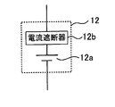
- the cell 12 includes a power generation element 12a and a current breaker 12b as shown in FIG.
- the power generation element 12 a and the current breaker 12 b are accommodated in a battery case that constitutes the exterior of the unit cell 12.
- the power generation element 12a is an element that performs charging and discharging, and includes a positive electrode plate, a negative electrode plate, and a separator disposed between the positive electrode plate and the negative electrode plate.
- the positive electrode plate includes a current collector plate and a positive electrode active material layer formed on the surface of the current collector plate.
- the negative electrode plate has a current collector plate and a negative electrode active material layer formed on the surface of the current collector plate.
- the positive electrode active material layer includes a positive electrode active material and a conductive agent
- the negative electrode active material layer includes a negative electrode active material and a conductive agent.
- the current collector plate of the positive electrode plate can be made of aluminum, and the current collector plate of the negative electrode plate can be made of copper.
- the positive electrode active material for example, LiCo 1/3 Ni 1/3 Mn 1/3 O 2 can be used, and as the negative electrode active material, for example, carbon can be used.
- An electrolyte solution is infiltrated into the separator, the positive electrode active material layer, and the negative electrode active material layer.
- a solid electrolyte layer may be disposed between the positive electrode plate and the negative electrode plate.
- the current breaker 12b is used to cut off the current path inside the unit cell 12. That is, when the current breaker 12b operates, the current path inside the unit cell 12 is cut off.
- a fuse for example, a fuse, a PTC (Positive Temperature Coefficient) element, or a current cut-off valve can be used. These current breakers 12b can be used individually or in combination.
- the fuse as the current breaker 12b is blown according to the current flowing through the fuse.
- the current path inside the unit cell 12 can be mechanically interrupted. Thereby, it can prevent that an excessive electric current flows into the electric power generation element 12a, and can protect the cell 12 (electric power generation element 12a).
- the fuse as the current breaker 12b can be accommodated in the battery case or can be provided outside the battery case. Even when a fuse is provided outside the battery case, a fuse is provided for each unit cell 12, and the fuse is connected in series with each unit cell 12.
- the PTC element as the current breaker 12b is arranged in the current path of the unit cell 12, and increases the resistance according to the temperature rise of the PTC element.
- the temperature of the PTC element rises due to Joule heat.
- the resistance of the PTC element increases as the temperature of the PTC element rises, current can be cut off in the PTC element. Thereby, it can prevent that an excessive electric current flows into the electric power generation element 12a, and can protect the cell 12 (electric power generation element 12a).
- the current cut-off valve as the current breaker 12b is deformed in accordance with the increase in the internal pressure of the unit cell 12, and can cut off the current path inside the unit cell 12 by breaking the mechanical connection with the power generation element 12a. it can.
- the inside of the unit cell 12 is in a sealed state, and when gas is generated from the power generation element 12a due to overcharging or the like, the internal pressure of the unit cell 12 increases.
- the unit cell 12 (power generation element 12a) is in an abnormal state.
- the mechanical connection with the power generation element 12a can be broken by deforming the current cutoff valve in response to the increase in the internal pressure of the unit cell 12. Thereby, it can block
- the monitoring unit 20 shown in FIG. 1 detects the voltage of each battery block 11 and outputs the detection result to the controller 40.
- the current sensor 31 detects the value of the current flowing through the assembled battery 10 and outputs the detection result to the controller 40. For example, when the assembled battery 10 is being discharged, a positive value can be used as the current value detected by the current sensor 31. Further, when the battery pack 10 is being charged, a negative value can be used as the current value detected by the current sensor 31.
- the current sensor 31 only needs to be able to detect the value of the current flowing through the assembled battery 10 and can be provided not on the positive electrode line PL but on the negative electrode line NL. A plurality of current sensors 31 can also be used. In consideration of cost, physique, etc., it is desirable to provide one current sensor 31 for one assembled battery 10 as in this embodiment.
- the controller 40 has a built-in memory 41, and the memory 41 stores a program for operating the controller 40 and specific information.
- the memory 41 can also be provided outside the controller 40.
- the process shown in FIG. 4 is performed at a predetermined cycle and executed by the controller 40.
- the process shown in FIG. 4 is performed for each battery block 11.
- step S101 the controller 40 acquires the internal resistance or full charge capacity of each battery block 11.
- Information about the acquired internal resistance or full charge capacity is stored in the memory 41.
- a known method can be used as appropriate.
- a method (an example) of acquiring the internal resistance of the battery block 11 will be described.
- the controller 40 can acquire the current value of the battery block 11 based on the output of the current sensor 31. Further, the controller 40 can acquire the voltage value of the battery block 11 based on the output of the monitoring unit 20. As shown in FIG. 5, the relationship between the acquired current value and voltage value is plotted in a coordinate system in which the horizontal axis is the current value and the vertical axis is the voltage value. Then, an approximate straight line L is calculated based on the plotted points. The slope of the approximate straight line L becomes the internal resistance of the battery block 11.
- the SOC State of Charge
- the SOC indicates the ratio of the current charge capacity to the full charge capacity of the battery block 11.
- the relationship between the current value and the voltage value is a linear relationship as shown in FIG. If the SOC of the battery block 11 changes while acquiring the current value and the voltage value, the relationship between the current value and the voltage value does not become a linear relationship, but the slope of the straight line L, in other words, the battery block. 11 is difficult to specify the internal resistance.
- the SOC of the battery block 11 is calculated (estimated) at different timings.
- the SOC calculated at the previous timing is called a start SOC
- the SOC calculated at the later timing is called an end SOC.
- a known method for calculating the SOC a known method can be appropriately used. For example, since SOC and OCV (Open Circuit Voltage) have a correspondence relationship, if this correspondence relationship is specified in advance, the SOC can be specified from the OCV.
- OCV Open Circuit Voltage
- a known method can be used as appropriate. For example, if the assembled battery 10 is left as it is, in other words, if the assembled battery 10 is not charged / discharged, the polarization state of the unit cell 12 can be eliminated. For this reason, if the voltage of the battery block 11 when the polarization state is eliminated is obtained, this voltage value can be regarded as OCV. Specifically, when starting the battery system after leaving the assembled battery 10, the voltage of the battery block 11 is detected by the monitoring unit 20 immediately after starting the battery system. The voltage detected by the monitoring unit 20 can be regarded as the OCV of the battery block 11.
- the current value flowing through the battery block 11 is integrated until the SOC of the battery block 11 changes from the start SOC to the end SOC to calculate the integrated value Ie.
- the current value flowing through the battery block 11 can be acquired by the current sensor 31.
- the controller 40 can calculate the full charge capacity of the battery block 11 based on the following formula (1).
- Equation (1) Smax represents the full charge capacity of the battery block 11, and Ie represents the current integrated value.
- SOC (1) indicates the start SOC, and SOC (2) indicates the end SOC.
- step S102 the controller 40 calculates a resistance change rate based on the internal resistance acquired in step S101 at each of the times t1 and t2.
- the resistance change rate can be calculated based on the following formula (2).
- the controller 40 calculates the capacity change rate based on the full charge capacity acquired in step S101 at each of the times t1 and t2.
- the capacity change rate can be calculated based on the following formula (3).
- Rr represents a resistance change rate.
- R1 indicates the internal resistance acquired at time t1, and R2 indicates the internal resistance acquired at time t2.
- Sr represents a capacity change rate. S1 indicates the full charge capacity acquired at time t1, and S2 indicates the full charge capacity acquired at time t2.
- Times t1 and t2 are different timings.
- the time t2 can be the current timing when the internal resistance or the full charge capacity is acquired.
- the time t1 can be the previous timing when the internal resistance or the full charge capacity is acquired. That is, time t1 is a timing before time t2.
- the time t1 may be the latest timing with respect to the time t2, or may be a timing before the latest timing.
- the time t1 may be any timing as long as it is before the time t2, and can be set as appropriate.
- Information about the internal resistance or the full charge capacity acquired at the timing before time t1 can be deleted from the memory 41. By deleting unnecessary information, the capacity of the memory 41 can be secured.
- step S103 the controller 40 determines whether or not the interval between the times t1 and t2 is within a predetermined period T.
- the predetermined period T can be determined based on the speed at which the deterioration of the battery block 11 proceeds.
- a method for determining the predetermined period T will be described.
- the change in internal resistance and the change in full charge capacity when the battery block 11 (unit cell 12) deteriorates can be obtained in advance by experiments.
- the wear deterioration is deterioration caused by wear of members (particularly the power generation element 12a) constituting the battery block 11 (unit cell 12).
- the change in internal resistance with time can be acquired in advance.
- the change in internal resistance with time can be obtained as a curve C1 shown in FIG.
- the internal resistance of the battery block 11 increases as time passes, in other words, as the wear deterioration of the battery block 11 progresses.
- a change with time of the full charge capacity can be acquired beforehand.
- the change with time of the full charge capacity can be acquired as a curve C2 shown in FIG. As shown in FIG. 7, as time elapses, in other words, as the wear deterioration of the battery block 11 progresses, the full charge capacity of the battery block 11 decreases.
- the internal resistance acquired at each of the times t1 and t2 is located on the curve C1 indicating the change over time of the internal resistance in FIG. It will be.
- the current breaker 12b when the current breaker 12b is activated, no current flows through the unit cell 12 including the current breaker 12b in the activated state. Therefore, immediately after the current breaker 12b is activated, Internal resistance increases. That is, the internal resistance of the battery block 11 when the current breaker 12b is activated is higher than the internal resistance corresponding to wear deterioration.
- the period when the internal resistance increases by a predetermined amount with respect to the internal resistance at time t1 due to wear deterioration of the battery block 11 can be specified in advance.
- the internal resistance at time t2 is increased by a predetermined amount with respect to the internal resistance at time t1
- the battery block 11 has not only increased internal resistance due to wear deterioration but also current. It can be determined that an increase in internal resistance due to the operation of the circuit breaker 12b has occurred.
- the internal resistance of the battery block 11 gradually increases, whereas when the current breaker 12b is activated, the internal resistance of the battery block 11 rapidly increases. Therefore, when the internal resistance of the battery block 11 increases by a predetermined amount in a period sufficiently shorter than the period until the internal resistance of the battery block 11 increases by a predetermined amount due to wear deterioration, the current breaker 12b is activated. Can be determined. By monitoring this time interval, it can be determined whether or not the current breaker 12b is operating.
- the internal resistance of the battery block 11 becomes 1.1 times when half a year has elapsed from time t1 based on the curve C1 shown in FIG.
- the internal resistance of the battery block 11 becomes 1.1 times between the time t1 and the time t2 even though the interval between the time t1 and the time t2 shown in FIG. 6 is within one month, It can be determined that the current breaker 12b is operating.
- the full charge capacity acquired at each of the times t1 and t2 is a curve C2 showing the change over time of the full charge capacity in FIG. Will be located on top.
- the full charge capacity of the battery block 11 is the sum of the full charge capacities of the plurality of single cells 12.
- the full charge capacity of the battery block 11 is the amount of the unit cell 12 in which no current flows. descend. That is, the full charge capacity of the battery block 11 when the current breaker 12b is activated is lower than the full charge capacity corresponding to wear deterioration.
- the full charge capacity of the battery block 11 gradually decreases, whereas when the current breaker 12b is activated, the full charge capacity of the battery block 11 rapidly decreases. Therefore, when the full charge capacity of the battery block 11 decreases by a predetermined amount in a period sufficiently shorter than the period until the full charge capacity of the battery block 11 decreases by a predetermined amount due to wear deterioration, the current breaker 12b is activated. It can be determined that it is. By monitoring this time interval, it can be determined whether or not the current breaker 12b is operating.
- the full charge capacity of the battery block 11 becomes 0.9 times when half a year has elapsed from time t1 based on the curve C2 shown in FIG.
- the full charge capacity of the battery block 11 becomes 0.9 times between the time t1 and the time t2 even though the interval between the time t1 and the time t2 shown in FIG. 7 is within one month. It can be determined that the current breaker 12b is operating.
- the predetermined period T is a period when the resistance change rate or the capacity change rate acquired in step S102 is generated only by wear deterioration. Specifically, the predetermined period T is a period until the rate of increase in internal resistance (the resistance change rate acquired in step S102) from time t1 to time t2 is generated, and the curve C1 shown in FIG. It is a period specified from Further, the predetermined period T is a period until the rate of decrease of the full charge capacity from the time t1 to the time t2 (capacity change rate acquired in step S102) occurs, and is specified from the curve C2 shown in FIG. It is a period.
- the controller 40 determines in the battery block 11 that the current breaker 12b is not operating.
- the process proceeds to step S104. That is, when the interval between the times t1 and t2 is within the predetermined period T, the controller 40 determines that the current breaker 12b is operating in the battery block 11.
- step S104 the controller 40 specifies the number of current breakers 12b in the operating state (referred to as the number of breaks) based on the resistance change rate Rr or the capacity change rate Sr calculated in step S102.
- the internal resistance of the battery block 11 before the current breaker 12b is activated is Ra and the internal resistance of the battery block 11 after the current breaker 12b is activated is Rb
- the internal resistances Ra and Rb are expressed by the following formula (4 ).
- the full charge capacity of the battery block 11 before the current breaker 12b is operated is Sa and the full charge capacity of the battery block 11 after the current breaker 12b is operated is Sb
- the full charge capacities Sa and Sb are And has the relationship shown in the following formula (5).
- N represents the number of the unit cells 12 constituting each battery block 11, in other words, the number of the unit cells 12 connected in parallel.
- m indicates the total number (the number of interruptions) of the current breakers 12b in the operating state in each battery block 11. Since the current breaker 12b is provided in each unit cell 12, the number of breaks m is the total number of the unit cells 12 having the current breaker 12b in the operating state. In the battery block 11, when all the current breakers 12b are not operating, the breaking number m is zero.
- the internal resistance of the battery block 11 is increased according to the number of current breakers 12b in the activated state. That is, as shown in Expression (4), the internal resistance Rb of the battery block 11 after the current breaker 12b is activated is N with respect to the internal resistance Ra of the battery block 11 before the current breaker 12b is activated. / (Nm) times. Since the value of “N / (N ⁇ m)” is a value larger than 1, the internal resistance Rb is higher than the internal resistance Ra.
- the full charge capacity of the battery block 11 is reduced according to the number of current breakers 12b in the activated state. That is, as shown in Expression (5), the full charge capacity Sb of the battery block 11 after the current breaker 12b is activated is compared with the full charge capacity Sa of the battery block 11 before the current breaker 12b is activated. , (N ⁇ m) / N times. Since the value of “(N ⁇ m) / N” is a value smaller than 1, the full charge capacity Sb is lower than the full charge capacity Sa.
- Expression (4) and Expression (5) are modified, they can be expressed by Expression (6) and Expression (7).
- a range (allowable value ⁇ 1) in which the error is allowed is determined in advance, and the cutoff number m can be calculated in consideration of the allowable value ⁇ 1.
- the value “N / (N ⁇ m)” is calculated while changing the number m. Then, it is determined whether or not the resistance change rate Rr is included in the allowable range.
- the value obtained by adding the allowable value ⁇ 1 to the calculated value “N / (N ⁇ m)” is set as the upper limit value of the allowable range, and the value obtained by subtracting the allowable value ⁇ 1 from the calculated value “N / (N ⁇ m)” Can be set as the lower limit of the allowable range.
- the number m at this time can be the total number of the current breakers 12b in the operating state.
- the allowable value ⁇ 1 can be changed according to the number N. That is, the allowable value ⁇ 1 can be reduced as the number N increases. In other words, the allowable value ⁇ 1 can be increased as the number N decreases.
- the allowable value ⁇ 1 may be determined in advance based on the number N.
- a range (allowable value ⁇ 2) in which the error is allowed is determined in advance, and the cutoff number m can be calculated in consideration of the allowable value ⁇ 2.
- the value “(N ⁇ m) / N” is calculated while changing the number m. Then, it is determined whether or not the capacity change rate Sr is included in the allowable range.
- the value obtained by adding the allowable value ⁇ 2 to the calculated value “(N ⁇ m) / N” is used as the upper limit value of the allowable range, and the value obtained by subtracting the allowable value ⁇ 2 from the calculated value “(N ⁇ m) / N” Can be set as the lower limit of the allowable range.
- the number m at this time can be the total number of the current breakers 12b in the operating state.
- the allowable value ⁇ 2 can be changed according to the number N. That is, the allowable value ⁇ 2 can be reduced as the number N increases. In other words, the allowable value ⁇ 2 can be increased as the number N decreases.
- the allowable value ⁇ 2 may be determined in advance based on the number N.
- either the resistance change rate Rr or the capacitance change rate Sr can be considered, or both the resistance change rate Rr and the capacitance change rate Sr can be considered.
- the resistance change rate Rr is calculated from the internal resistances R1 and R2 acquired at the times t1 and t2, and the cutoff number m is calculated from the resistance change rate Rr.
- the present invention is not limited to this.
- the resistance change rate Rr is calculated from the internal resistance of the battery block 11 acquired at a predetermined time and the internal resistance at a predetermined time specified from the change over time of the internal resistance obtained in advance (curve C1 in FIG. 6). can do. That is, in the process of step S101, the internal resistance of the battery block 11 is acquired, and the internal resistance at the same time as when the process of step S101 is performed is specified from the curve C1 in FIG.
- the internal resistance specified from the curve C1 in FIG. 6 can be used as R1 shown in Expression (2).
- the internal resistance acquired by the process of step S101 can be used as R2 shown in Formula (2). If the resistance change rate Rr can be calculated, the cutoff number m can be calculated by the method described in this embodiment.
- the capacity change rate Sr is calculated from the full charge capacities S1 and S2 acquired at the times t1 and t2, and the cutoff number m is calculated from the capacity change rate Sr.
- the present invention is not limited to this. .
- the capacity change rate from the full charge capacity of the battery block 11 acquired at a predetermined time and the full charge capacity at a predetermined time specified from a change with time of the full charge capacity obtained in advance (curve C2 in FIG. 7).
- Sr can be calculated. That is, in the process of step S101, the full charge capacity of the battery block 11 is acquired, and the full charge capacity at the same time as when the process of step S101 is performed is specified from the curve C2 in FIG.
- the full charge capacity specified from the curve C2 of FIG. 7 can be used as S1 shown in Expression (3).
- the full charge capacity acquired by the process of step S101 can be used. If the capacity change rate Sr can be calculated, the blocking number m can be calculated by the method described in this embodiment.
- the present invention is not limited to this. It is not a thing.
- the internal resistance of the battery block 11 is acquired, and when the acquired internal resistance is higher than the internal resistance corresponding to the wear deterioration of the battery block 11, it is determined that the current breaker 12b is in an operating state. be able to. In other words, when the acquired internal resistance is shifted to the higher resistance side with respect to the curve of internal resistance corresponding to wear deterioration (curve C1 shown in FIG. 6), the current breaker 12b is in an operating state. Can be determined.
- the current breaker 12b when the full charge capacity of the battery block 11 is acquired and the acquired full charge capacity becomes lower than the full charge capacity corresponding to the wear deterioration of the battery block 11, the current breaker 12b is in an operating state. Can be determined. In other words, when the acquired full charge capacity is deviated toward the lower side of the full charge capacity curve (curve C2 shown in FIG. 7) corresponding to wear deterioration, the current breaker 12b is in the operating state. It can be determined that there is.
- the controller 40 can control charging / discharging of the assembled battery 10 based on the shut-off number m.
- High-rate deterioration is deterioration due to the fact that the salt concentration in the electrolyte solution of the unit cell 12 is biased to one side (positive electrode side or negative electrode side) when charging or discharging is performed at a high rate. If the salt concentration is biased to one side, the movement of ions between the positive electrode and the negative electrode is suppressed, so that the input / output performance of the unit cell 12 is deteriorated and the unit cell 12 is deteriorated.
- lithium when a lithium ion secondary battery is used as the single battery 12, lithium may be easily deposited.
- lithium ions moving between the positive electrode and the negative electrode are decreased, and as a result, the full charge capacity of the unit cell 12 is decreased.
- the current breaker 12b when the value of the current flowing through the unit cell 12 increases, the current breaker 12b may be easily activated.
- the controller 40 can determine a current command value for controlling charging / discharging of the assembled battery 10 based on the number m of interruptions when the number m of interruptions is specified. Specifically, the controller 40 can reduce the charge / discharge current of the assembled battery 10 as the current command value increases as the number of interruptions m increases. The controller 40 can set the current command value based on the following formula (8).
- Is (2) Is (1) ⁇ (N ⁇ m) / N (8)
- Is (1) is a current command value before the current breaker 12b is activated
- Is (2) is a current command value after the current breaker 12b is activated.
- the current command value Is (2) is smaller than the current command value Is (1).
- the controller 40 can control charging / discharging of the assembled battery 10 based on the current command value Is (2). Specifically, the controller 40 reduces the upper limit power that allows charging of the assembled battery 10 or decreases the upper limit power that allows discharging of the assembled battery 10 based on the current command value Is (2). . When lowering the upper limit power, the upper limit power before being lowered can be multiplied by a value of “(N ⁇ m) / N”. By reducing the upper limit power that allows charging / discharging of the assembled battery 10, the value of the current flowing through the assembled battery 10 (unit cell 12) can be limited.
- the controller 40 can prevent the assembled battery 10 from being charged / discharged. Specifically, the controller 40 can set the upper limit power that allows charging and discharging of the assembled battery 10 to 0 [kW]. Further, the controller 40 can turn off the system main relays SMR-B, SMR-G, and SMR-P.
- the battery pack 10 can be prevented from being charged / discharged when the shut-off number m approaches “N”.
- the number of shut-off numbers m when charging / discharging of the assembled battery 10 is not performed can be appropriately set based on the viewpoint of ensuring the traveling of the vehicle.
- the charge / discharge control of the assembled battery 10 is performed not only when the battery system shown in FIG. 1 is activated, but also when the power of the external power source is supplied to the assembled battery 10 or when the power of the assembled battery 10 is supplied to an external device. It can also be done while feeding.
- the external power source is a power source provided outside the vehicle, and for example, a commercial power source can be used as the external power source.
- the external device is an electronic device arranged outside the vehicle, and is an electronic device that operates by receiving electric power from the assembled battery 10. As the external device, for example, a home appliance can be used.
- a charger When supplying power from the external power source to the assembled battery 10, a charger can be used.
- the charger can convert AC power from an external power source into DC power and supply the DC power to the assembled battery 10.
- the charger can be mounted on the vehicle or can be provided outside the vehicle separately from the vehicle. Further, the charger can convert the voltage value in consideration of the voltage of the external power supply and the voltage of the assembled battery 10.
- the controller 40 can reduce the current value (charging current) of the assembled battery 10 by controlling the operation of the charger.
- a power feeding device When supplying the power of the assembled battery 10 to an external device, a power feeding device can be used.
- the power feeding device can convert DC power from the assembled battery 10 into AC power and supply the AC power to an external device. Further, the power supply device can convert the voltage value in consideration of the voltage of the assembled battery 10 and the operating voltage of the external device.
- the controller 40 can reduce the current value (discharge current) of the assembled battery 10 by controlling the operation of the power supply apparatus.
- operating can also be restrict
- charging / discharging of the assembled battery 10 can be controlled according to the number of interruptions m, charging / discharging control of the assembled battery 10 can be performed efficiently.
- the charging / discharging of the assembled battery 10 may be excessively limited only by detecting the operating state of the current breaker 12b.
- charging / discharging of the assembled battery 10 can be restricted according to the number of interruptions m, and charging / discharging of the assembled battery 10 is prevented from being excessively restricted. can do.
- a battery system that is Embodiment 2 of the present invention will be described.
- the member which has the same function as the member demonstrated in Example 1 detailed description is abbreviate
- differences from the first embodiment will be mainly described.
- FIG. 8 is a flowchart showing a process of specifying the number of current breakers 12b in the operating state in the present embodiment. The process shown in FIG. 8 is performed at a predetermined cycle and executed by the controller 40. The process shown in FIG. 8 is performed for each battery block 11.
- step S ⁇ b> 101 of FIG. 8 the controller 40 acquires the internal resistance and the full charge capacity in each battery block 11.
- step S102 the controller 40 calculates the resistance change rate Rr based on the internal resistance acquired in step S101, and calculates the capacity change rate Sr based on the full charge capacity acquired in step S101.
- the resistance change rate Rr and the capacitance change rate Sr can be calculated by the method described in the first embodiment.
- step S105 the controller 40 multiplies the resistance change rate Rr and the capacitance change rate Sr, and determines whether or not the multiplied value is 1.
- the resistance change rate Rr becomes equal to the value of “N / (N ⁇ m)”.
- the capacity change rate Sr is equal to the value of “(N ⁇ m) / N”.
- multiplying the resistance change rate Rr and the capacitance change rate Sr means multiplying the values of “N / (N ⁇ m)” and “(N ⁇ m) / N”, and the multiplied value is 1
- a range (allowable value ⁇ ) in which the error is allowed can be set.
- the controller 40 can determine whether or not the value obtained by multiplying the resistance change rate Rr and the capacitance change rate Sr is within an allowable range.
- a value obtained by adding the allowable value ⁇ to 1 can be used as the upper limit value of the allowable range, and a value obtained by subtracting the allowable value ⁇ from 1 can be used as the lower limit value of the allowable range.
- step S103 When the value obtained by multiplying the resistance change rate Rr and the capacitance change rate Sr is within the allowable range, the process proceeds to step S103.
- step S103 When the value obtained by multiplying the resistance change rate Rr and the capacitance change rate Sr is out of the allowable range, the processing shown in FIG. 8 ends.
- steps S103 and S104 are the same as those described in the first embodiment (steps S103 and S104 in FIG. 4).
- the resistance change rate Rr has a value of “N / (N ⁇ m)” but also the capacity change rate Sr has a value of “(N ⁇ m) / N”. Therefore, it is possible to determine whether or not the current breaker 12b is operating by confirming the relationship between the resistance change rate Rr and the capacitance change rate Sr.
- the accuracy of determining the operating state of the current breaker 12b is improved as compared with the case where only one of the resistance change rate Rr and the capacity change rate Cr is considered. Can be made.
- the deterioration of the battery block 11 may include not only wear deterioration but also the above-described high rate deterioration. Further, when the unit cell 12 is a lithium ion secondary battery, the deterioration of the battery block 11 may include deterioration due to lithium deposition.
- the internal resistance of the battery block 11 increases and becomes higher than the internal resistance corresponding to the wear deterioration (curve C1 shown in FIG. 6).
- the full charge capacity of the battery block 11 is lowered and becomes lower than the full charge capacity (curve C2 shown in FIG. 7) corresponding to wear deterioration.
- the internal resistance of the battery block 11 may deviate from the curve C1 shown in FIG.
- the full charge capacity of the battery block 11 may deviate from the curve C2 shown in FIG. In this case, an erroneous determination may be made when determining the operating state of the current breaker 12b.
- the influence of high rate deterioration and lithium precipitation is excluded.
- the operating state of the current breaker 12b can be determined.
- the time constant when high-rate deterioration occurs and the time constant when lithium deposition occurs tend to be different from each other. In other words, high-rate deterioration and lithium deposition are unlikely to occur at the same timing.
- the operation of the current breaker 12b is performed in a state where the influence of high rate deterioration and lithium deposition is excluded. Only the state can be determined.
- a battery system that is Embodiment 3 of the present invention will be described.
- the member which has the same function as the member demonstrated in Example 1 detailed description is abbreviate
- differences from the first embodiment will be mainly described.
- the resistance change rate Rr is calculated from the internal resistance acquired at times t1 and t2, and the cutoff number m is calculated from the resistance change rate Rr.
- the block number m is calculated by comparing the internal resistances of the plurality of battery blocks 11 with each other. This point will be specifically described.
- the internal resistance of the battery block 11 including the current breaker 12b in the activated state is all It becomes higher than the internal resistance of the battery block 11 in which the current breaker 12b is not activated.
- the internal resistances of all the unit cells 12 constituting the assembled battery 10 are equal. In other words, the internal resistances of all the battery blocks 11 constituting the assembled battery 10 are assumed to be equal.
- the current breaker 12b hardly operates at the same time, and the assembled battery 10 includes the battery block 11 including the current breaker 12b in the active state and all the current breakers.
- the battery block 11 in which 12b is not operating is mixed.
- the battery block 11 having the higher internal resistance can be specified.
- the battery block 11 including the circuit breaker 12b can be specified.
- the internal resistance of each battery block 11 can be obtained by the method described in the first embodiment.
- the number m of interruptions can be calculated. Specifically, the resistance change rate Rr is calculated based on the internal resistance of each battery block 11 and the internal resistance of other battery blocks 11. In the first embodiment, the resistance change rate Rr is calculated from the internal resistance at the times t1 and t2. However, in this embodiment, the internal resistance in the two battery blocks 11 is used instead of the internal resistance at the times t1 and t2. ing.
- the method of calculating the resistance change rate Rr is the same as the method described in the first embodiment. Specifically, the resistance change rate Rr can be calculated using the equation (2) described in the first embodiment. In Formula (2), the internal resistance of one battery block 11 can be used as the internal resistance R1, and the internal resistance of the other battery block 11 can be used as the internal resistance R2. By calculating the resistance change rate Rr from the internal resistances in the two battery blocks 11, the number m of interruptions can be calculated from the resistance change rate Rr as in the first embodiment.
- the cutoff number m can be calculated. Specifically, the full charge capacity of each battery block 11 is acquired, and the capacity change rate Sr is calculated based on the full charge capacity of each battery block 11 and the full charge capacity of other battery blocks 11. In the first embodiment, the capacity change rate Sr is calculated from the full charge capacity at the times t1 and t2. However, in this embodiment, the full charge in the two battery blocks 11 is used instead of the full charge capacity at the times t1 and t2. Capacity is used.
- the method for calculating the capacity change rate Sr is the same as the method described in the first embodiment. Specifically, the capacity change rate Sr can be calculated using the equation (3) described in the first embodiment. In Expression (3), the full charge capacity of one battery block 11 can be used as the full charge capacity S1, and the full charge capacity of the other battery block 11 can be used as the full charge capacity S2. By calculating the capacity change rate Sr from the full charge capacities in the two battery blocks 11, the interruption number m can be calculated from the capacity change rate Sr as in the first embodiment.
- the cutoff number m can be calculated based on the voltage change amount ⁇ V of each battery block 11 instead of the internal resistance of each battery block 11.
- the voltage change amount ⁇ V of each battery block 11 can be calculated based on the following formula (9).
- I is a current value flowing through each battery block 11
- R is an internal resistance of each battery block 11.
- the interruption number m can be calculated by using the ratio of the voltage change amount ⁇ V in the two battery blocks 11. .
- the internal resistance of the battery block 11 depends on the temperature and SOC of the battery block 11. For this reason, when calculating the number of interruptions m using the voltage change amount ⁇ V, it is preferable that the temperature and SOC are uniform in the plurality of battery blocks 11.
- the SOC in the plurality of battery blocks 11 can be equalized by performing the equalization process on the plurality of battery blocks 11.
- the voltage in each of the battery blocks 11 can be equalized by detecting the voltage of each battery block 11 and discharging the battery block 11 on the higher voltage side.
- the SOC can be equalized.
- the temperatures in the plurality of battery blocks 11 can be equalized. If a plurality of temperature sensors are arranged for the plurality of battery blocks 11, it is possible to confirm whether or not the temperatures in the plurality of battery blocks 11 are equalized from the detection results of the plurality of temperature sensors.
- the voltage change amount ⁇ V is a value obtained by subtracting the OCV of each battery block 11 from the voltage (CCV; Closed Circuit Voltage) of each battery block 11 detected by the monitoring unit 20.
- the method for obtaining the OCV of the battery block 11 is the same as the method described in the first embodiment.
- the value detected by the current sensor 31 may not be used when calculating the number of interruptions m by calculating the number of interruptions m based on the voltage change amount ⁇ V calculated from the CCV and OCV of the battery block 11. Thereby, the detection error by the current sensor 31 can be ignored.
Abstract
Description
Sr=S2/S1 ・・・(3)
Sb=Sa×(N-m)/N ・・・(5)
Sb/Sa=(N-m)/N ・・・(7)
Claims (10)
- 並列に接続された複数の蓄電素子をそれぞれ有し、直列に接続された複数の蓄電ブロックと、
前記各蓄電ブロックの状態を判別するコントローラと、を有し、
前記各蓄電素子は、前記蓄電素子の内部における電流経路を遮断する電流遮断器を有しており、
前記コントローラは、
前記各蓄電ブロックの内部抵抗および満充電容量の少なくとも一方のパラメータを取得し、
取得した前記パラメータと、遮断状態にある前記電流遮断器を含まない前記蓄電ブロックにおける前記パラメータの基準値との間の変化率を用いて、前記各蓄電ブロックにおいて、遮断状態にある前記電流遮断器の数である遮断数を特定することを特徴とする蓄電システム。 - 前記コントローラは、現在の前記パラメータと、前記基準値としての過去の前記パラメータとの間の変化率を用いて、前記遮断数を特定することを特徴とする請求項1に記載の蓄電システム。
- 前記基準値は、他の前記蓄電ブロックにおける前記パラメータであることを特徴とする請求項1に記載の蓄電システム。
- 前記基準値は、前記蓄電ブロックの劣化に応じて変化し、予め特定された前記パラメータであることを特徴とする請求項1に記載の蓄電システム。
- 前記コントローラは、前記各蓄電ブロックの内部抵抗を取得し、取得した内部抵抗が、前記蓄電ブロックの劣化に伴う内部抵抗よりも高いとき、前記遮断数の特定を行うことを特徴とする請求項4に記載の蓄電システム。
- 前記コントローラは、前記各蓄電ブロックの満充電容量を取得し、取得した満充電容量が、前記蓄電ブロックの劣化に伴う満充電容量よりも低いとき、前記遮断数の特定を行うことを特徴とする請求項4に記載の蓄電システム。
- 前記コントローラは、前記内部抵抗の値として、前記各蓄電ブロックの内部抵抗の変化に応じて変化する電圧変化量の値を用いることを特徴とする請求項1から4のいずれか1つに記載の蓄電システム。
- 前記コントローラは、前記内部抵抗に関する前記変化率と、前記満充電容量に関する前記変化率とを乗算した値が、1を基準とした許容範囲内に含まれるとき、前記遮断数の特定を行うことを特徴とする請求項1から7のいずれか1つに記載の蓄電システム。
- 前記電流遮断器は、溶断によって前記電流経路を遮断するヒューズ、温度上昇に伴う抵抗の上昇によって前記電流経路を遮断するPTC素子又は、前記蓄電素子の内圧が上昇することに応じて変形し、前記電流経路を遮断する電流遮断弁であることを特徴とする請求項1から8のいずれか1つに記載の蓄電システム。
- 並列に接続された複数の蓄電素子をそれぞれ有し、直列に接続された複数の蓄電ブロックの状態を判別する方法であって、
前記各蓄電素子は、前記蓄電素子の内部における電流経路を遮断する電流遮断器を有しており、
前記各蓄電ブロックの内部抵抗および満充電容量の少なくとも一方のパラメータを取得し、
取得した前記パラメータと、遮断状態にある前記電流遮断器を含まない前記蓄電ブロックにおける前記パラメータの基準値との間の変化率を用いて、前記各蓄電ブロックにおいて、遮断状態にある前記電流遮断器の数である遮断数を特定することを特徴とする判別方法。
Priority Applications (5)
| Application Number | Priority Date | Filing Date | Title |
|---|---|---|---|
| PCT/JP2012/000750 WO2013114468A1 (ja) | 2012-02-03 | 2012-02-03 | 蓄電システム |
| US14/355,724 US9933491B2 (en) | 2012-02-03 | 2012-02-03 | Electric storage system |
| CN201280067499.7A CN104054214B (zh) | 2012-02-03 | 2012-02-03 | 蓄电系统 |
| DE112012005805.4T DE112012005805B4 (de) | 2012-02-03 | 2012-02-03 | Elektrisches Speichersystem und Verfahren zum Bestimmen eines Zustands einer Vielzahl von elektrischen Speicherblöcken |
| JP2013556038A JP5811193B2 (ja) | 2012-02-03 | 2012-02-03 | 蓄電システム |
Applications Claiming Priority (1)
| Application Number | Priority Date | Filing Date | Title |
|---|---|---|---|
| PCT/JP2012/000750 WO2013114468A1 (ja) | 2012-02-03 | 2012-02-03 | 蓄電システム |
Publications (1)
| Publication Number | Publication Date |
|---|---|
| WO2013114468A1 true WO2013114468A1 (ja) | 2013-08-08 |
Family
ID=48904558
Family Applications (1)
| Application Number | Title | Priority Date | Filing Date |
|---|---|---|---|
| PCT/JP2012/000750 WO2013114468A1 (ja) | 2012-02-03 | 2012-02-03 | 蓄電システム |
Country Status (5)
| Country | Link |
|---|---|
| US (1) | US9933491B2 (ja) |
| JP (1) | JP5811193B2 (ja) |
| CN (1) | CN104054214B (ja) |
| DE (1) | DE112012005805B4 (ja) |
| WO (1) | WO2013114468A1 (ja) |
Cited By (3)
| Publication number | Priority date | Publication date | Assignee | Title |
|---|---|---|---|---|
| JP2017126462A (ja) * | 2016-01-13 | 2017-07-20 | トヨタ自動車株式会社 | 電池システム |
| JP2019148460A (ja) * | 2018-02-26 | 2019-09-05 | トヨタ自動車株式会社 | 電池システム |
| CN114096433A (zh) * | 2019-07-29 | 2022-02-25 | 株式会社Lg新能源 | 用于管理电池的设备和用于管理电池的方法 |
Families Citing this family (32)
| Publication number | Priority date | Publication date | Assignee | Title |
|---|---|---|---|---|
| ES2732298T3 (es) | 2005-07-26 | 2019-11-21 | Knauf Insulation Gmbh | Un método de fabricación de productos de aislamiento de fibra de vidrio |
| EP2108026A1 (en) | 2007-01-25 | 2009-10-14 | Knauf Insulation Limited | Composite wood board |
| SI2108006T1 (sl) | 2007-01-25 | 2021-02-26 | Knauf Insulation Gmbh | Veziva in s tem narejeni materiali |
| CN101668713B (zh) | 2007-01-25 | 2012-11-07 | 可耐福保温材料有限公司 | 矿物纤维板 |
| WO2008127936A2 (en) | 2007-04-13 | 2008-10-23 | Knauf Insulation Gmbh | Composite maillard-resole binders |
| GB0715100D0 (en) | 2007-08-03 | 2007-09-12 | Knauf Insulation Ltd | Binders |
| US8900495B2 (en) | 2009-08-07 | 2014-12-02 | Knauf Insulation | Molasses binder |
| WO2011138459A1 (en) | 2010-05-07 | 2011-11-10 | Knauf Insulation | Carbohydrate binders and materials made therewith |
| WO2011138458A1 (en) | 2010-05-07 | 2011-11-10 | Knauf Insulation | Carbohydrate polyamine binders and materials made therewith |
| EP2576882B1 (en) | 2010-06-07 | 2015-02-25 | Knauf Insulation | Fiber products having temperature control additives |
| WO2012152731A1 (en) | 2011-05-07 | 2012-11-15 | Knauf Insulation | Liquid high solids binder composition |
| CN103688438B (zh) * | 2012-02-01 | 2016-03-02 | 丰田自动车株式会社 | 蓄电系统以及用于判别蓄电块的状态的方法 |
| JP5811193B2 (ja) | 2012-02-03 | 2015-11-11 | トヨタ自動車株式会社 | 蓄電システム |
| GB201206193D0 (en) | 2012-04-05 | 2012-05-23 | Knauf Insulation Ltd | Binders and associated products |
| GB201214734D0 (en) | 2012-08-17 | 2012-10-03 | Knauf Insulation Ltd | Wood board and process for its production |
| US11401204B2 (en) | 2014-02-07 | 2022-08-02 | Knauf Insulation, Inc. | Uncured articles with improved shelf-life |
| JP2015191878A (ja) * | 2014-03-31 | 2015-11-02 | 株式会社日立製作所 | リチウムイオン二次電池システムおよびリチウムイオン二次電池の状態診断方法 |
| GB201408909D0 (en) | 2014-05-20 | 2014-07-02 | Knauf Insulation Ltd | Binders |
| DE102015002070A1 (de) | 2015-02-18 | 2016-08-18 | Audi Ag | Batteriezelle für eine Batterie eines Kraftfahrzeugs, Batterie und Kraftfahrzeug |
| GB201517867D0 (en) | 2015-10-09 | 2015-11-25 | Knauf Insulation Ltd | Wood particle boards |
| JP6387940B2 (ja) * | 2015-10-22 | 2018-09-12 | 株式会社オートネットワーク技術研究所 | 車載用電源装置 |
| GB201610063D0 (en) | 2016-06-09 | 2016-07-27 | Knauf Insulation Ltd | Binders |
| KR102285148B1 (ko) * | 2016-08-22 | 2021-08-04 | 삼성에스디아이 주식회사 | 배터리 충전 방법 및 이를 이용하는 배터리 충전 장치 |
| GB201701569D0 (en) | 2017-01-31 | 2017-03-15 | Knauf Insulation Ltd | Improved binder compositions and uses thereof |
| CN110383095B (zh) * | 2017-11-29 | 2022-08-26 | 株式会社东芝 | 评价装置、蓄电系统、评价方法以及计算机程序 |
| GB201804907D0 (en) | 2018-03-27 | 2018-05-09 | Knauf Insulation Ltd | Composite products |
| GB201804908D0 (en) | 2018-03-27 | 2018-05-09 | Knauf Insulation Ltd | Binder compositions and uses thereof |
| CN109067003B (zh) * | 2018-08-14 | 2020-08-07 | 中南大学 | 一种针对级联储能系统的soc平衡控制系统 |
| KR20210064931A (ko) * | 2019-11-26 | 2021-06-03 | 주식회사 엘지에너지솔루션 | 배터리 상태 진단 장치 및 방법 |
| JP2021092403A (ja) * | 2019-12-06 | 2021-06-17 | 東芝インフラシステムズ株式会社 | 蓄電池装置、方法及びプログラム |
| DE102020117706B4 (de) * | 2020-07-06 | 2023-04-20 | Man Truck & Bus Se | Technik zur Bestimmung mechanischer Spannungen in einem Traktionsenergiespeicher |
| US20220102769A1 (en) * | 2020-09-30 | 2022-03-31 | GM Global Technology Operations LLC | Architecture for battery self heating |
Citations (3)
| Publication number | Priority date | Publication date | Assignee | Title |
|---|---|---|---|---|
| JP2006138750A (ja) * | 2004-11-12 | 2006-06-01 | Matsushita Electric Ind Co Ltd | 電池監視装置 |
| JP2008182779A (ja) * | 2007-01-23 | 2008-08-07 | Matsushita Electric Ind Co Ltd | 電源機器 |
| JP2009216448A (ja) * | 2008-03-07 | 2009-09-24 | Nissan Motor Co Ltd | 組電池の異常検出装置 |
Family Cites Families (11)
| Publication number | Priority date | Publication date | Assignee | Title |
|---|---|---|---|---|
| JPH05275116A (ja) | 1992-03-26 | 1993-10-22 | Ngk Insulators Ltd | 集合電池の過電圧保護装置 |
| JP4157317B2 (ja) | 2002-04-10 | 2008-10-01 | 株式会社日立製作所 | 状態検知装置及びこれを用いた各種装置 |
| JP2006197790A (ja) | 2004-12-15 | 2006-07-27 | Matsushita Electric Ind Co Ltd | 電源装置 |
| JP4501812B2 (ja) | 2005-08-09 | 2010-07-14 | トヨタ自動車株式会社 | 最大出力設定装置およびこれを備える駆動装置並びにこれを備える動力出力装置、これを搭載する自動車、最大出力設定方法 |
| JP5319224B2 (ja) * | 2008-09-25 | 2013-10-16 | 株式会社東芝 | 組電池システム |
| JP5427521B2 (ja) * | 2009-09-04 | 2014-02-26 | 株式会社マキタ | 電池パック |
| JP2011135657A (ja) | 2009-12-22 | 2011-07-07 | Sanyo Electric Co Ltd | バッテリシステム及びこれを備える車両並びにバッテリシステムの電流制限状態検出方法 |
| JP2011137682A (ja) | 2009-12-28 | 2011-07-14 | Panasonic Corp | 電池異常検出回路、電池電源装置、及び電池電源システム。 |
| CN102472802A (zh) | 2010-03-26 | 2012-05-23 | 松下电器产业株式会社 | 充电状态检测电路、电池电源装置以及电池信息监视装置 |
| CN103688438B (zh) | 2012-02-01 | 2016-03-02 | 丰田自动车株式会社 | 蓄电系统以及用于判别蓄电块的状态的方法 |
| JP5811193B2 (ja) | 2012-02-03 | 2015-11-11 | トヨタ自動車株式会社 | 蓄電システム |
-
2012
- 2012-02-03 JP JP2013556038A patent/JP5811193B2/ja active Active
- 2012-02-03 WO PCT/JP2012/000750 patent/WO2013114468A1/ja active Application Filing
- 2012-02-03 CN CN201280067499.7A patent/CN104054214B/zh active Active
- 2012-02-03 US US14/355,724 patent/US9933491B2/en active Active
- 2012-02-03 DE DE112012005805.4T patent/DE112012005805B4/de active Active
Patent Citations (3)
| Publication number | Priority date | Publication date | Assignee | Title |
|---|---|---|---|---|
| JP2006138750A (ja) * | 2004-11-12 | 2006-06-01 | Matsushita Electric Ind Co Ltd | 電池監視装置 |
| JP2008182779A (ja) * | 2007-01-23 | 2008-08-07 | Matsushita Electric Ind Co Ltd | 電源機器 |
| JP2009216448A (ja) * | 2008-03-07 | 2009-09-24 | Nissan Motor Co Ltd | 組電池の異常検出装置 |
Cited By (7)
| Publication number | Priority date | Publication date | Assignee | Title |
|---|---|---|---|---|
| JP2017126462A (ja) * | 2016-01-13 | 2017-07-20 | トヨタ自動車株式会社 | 電池システム |
| JP2019148460A (ja) * | 2018-02-26 | 2019-09-05 | トヨタ自動車株式会社 | 電池システム |
| JP7000201B2 (ja) | 2018-02-26 | 2022-01-19 | トヨタ自動車株式会社 | 電池システム |
| CN114096433A (zh) * | 2019-07-29 | 2022-02-25 | 株式会社Lg新能源 | 用于管理电池的设备和用于管理电池的方法 |
| JP2022539799A (ja) * | 2019-07-29 | 2022-09-13 | エルジー エナジー ソリューション リミテッド | 電池管理装置および電池管理方法 |
| JP7338126B2 (ja) | 2019-07-29 | 2023-09-05 | エルジー エナジー ソリューション リミテッド | 電池管理装置および電池管理方法 |
| CN114096433B (zh) * | 2019-07-29 | 2024-03-01 | 株式会社Lg新能源 | 管理电池设备和管理电池方法 |
Also Published As
| Publication number | Publication date |
|---|---|
| DE112012005805T5 (de) | 2014-10-16 |
| US20140335387A1 (en) | 2014-11-13 |
| CN104054214B (zh) | 2017-04-05 |
| DE112012005805B4 (de) | 2024-01-04 |
| JP5811193B2 (ja) | 2015-11-11 |
| CN104054214A (zh) | 2014-09-17 |
| US9933491B2 (en) | 2018-04-03 |
| JPWO2013114468A1 (ja) | 2015-05-11 |
Similar Documents
| Publication | Publication Date | Title |
|---|---|---|
| JP5811193B2 (ja) | 蓄電システム | |
| JP5962762B2 (ja) | 蓄電システム | |
| JP5682708B2 (ja) | 蓄電システム | |
| JP5835341B2 (ja) | リチウムイオン二次電池の制御装置および制御方法 | |
| JP2013145175A (ja) | 電池システムおよび短絡検出方法 | |
| JP2013168285A (ja) | 電池システムおよび非水二次電池の充放電制御方法 | |
| JP2016005304A (ja) | 車両 | |
| JP5692040B2 (ja) | 蓄電システム | |
| JP5626190B2 (ja) | 蓄電システム | |
| JP5472472B2 (ja) | 蓄電システムおよび蓄電ブロックの状態を判別する方法 | |
| JP6017790B2 (ja) | 蓄電システム | |
| EP3912844B1 (en) | Charging control system | |
| JP5626195B2 (ja) | 蓄電システム | |
| JP5867373B2 (ja) | 電池システムおよび、リチウムイオン二次電池の内部抵抗の推定方法 | |
| JP5794205B2 (ja) | 蓄電システムおよび断線判別方法 | |
| JP2015061505A (ja) | 蓄電システム | |
| JP5737200B2 (ja) | 蓄電システム | |
| JP5870907B2 (ja) | 蓄電システム | |
| JP5733238B2 (ja) | 蓄電システム | |
| WO2013114467A1 (ja) | 蓄電システム | |
| JP5678879B2 (ja) | 蓄電システムおよび異常判定方法 | |
| JP5692047B2 (ja) | 蓄電システム | |
| JP2014023278A (ja) | 蓄電システム |
Legal Events
| Date | Code | Title | Description |
|---|---|---|---|
| 121 | Ep: the epo has been informed by wipo that ep was designated in this application |
Ref document number: 12867120 Country of ref document: EP Kind code of ref document: A1 |
|
| ENP | Entry into the national phase |
Ref document number: 2013556038 Country of ref document: JP Kind code of ref document: A |
|
| WWE | Wipo information: entry into national phase |
Ref document number: 14355724 Country of ref document: US |
|
| WWE | Wipo information: entry into national phase |
Ref document number: 112012005805 Country of ref document: DE Ref document number: 1120120058054 Country of ref document: DE |
|
| 122 | Ep: pct application non-entry in european phase |
Ref document number: 12867120 Country of ref document: EP Kind code of ref document: A1 |