本発明の実施例1である電池システム(蓄電システムに相当する)について、図1を用いて説明する。図1は、電池システムの構成を示す図である。本実施例の電池システムは、車両に搭載されている。
A battery system (corresponding to a power storage system) that is Embodiment 1 of the present invention will be described with reference to FIG. FIG. 1 is a diagram illustrating a configuration of a battery system. The battery system of this embodiment is mounted on a vehicle.
車両としては、ハイブリッド自動車や電気自動車がある。ハイブリッド自動車は、車両を走行させる動力源として、後述する組電池に加えて、エンジン又は燃料電池を備えている。電気自動車は、車両を走行させる動力源として、後述する組電池だけを備えている。
Vehicles include hybrid cars and electric cars. The hybrid vehicle includes an engine or a fuel cell as a power source for running the vehicle in addition to the assembled battery described later. The electric vehicle includes only an assembled battery described later as a power source for running the vehicle.
組電池10の正極端子と接続された正極ラインPLには、システムメインリレーSMR-Bが設けられている。システムメインリレーSMR-Bは、コントローラ40からの制御信号を受けることにより、オンおよびオフの間で切り替わる。組電池10の負極端子と接続された負極ラインNLには、システムメインリレーSMR-Gが設けられている。システムメインリレーSMR-Gは、コントローラ40からの制御信号を受けることにより、オンおよびオフの間で切り替わる。
The system main relay SMR-B is provided on the positive line PL connected to the positive terminal of the assembled battery 10. System main relay SMR-B is switched between on and off by receiving a control signal from controller 40. A system main relay SMR-G is provided on the negative electrode line NL connected to the negative electrode terminal of the assembled battery 10. System main relay SMR-G is switched between on and off by receiving a control signal from controller 40.
システムメインリレーSMR-Gには、システムメインリレーSMR-Pおよび電流制限抵抗Rが並列に接続されている。システムメインリレーSMR-Pおよび電流制限抵抗Rは、直列に接続されている。システムメインリレーSMR-Pは、コントローラ40からの制御信号を受けることにより、オンおよびオフの間で切り替わる。電流制限抵抗Rは、組電池10を負荷(具体的には、後述する昇圧回路32)と接続するときに、突入電流が流れるのを抑制するために用いられる。
System main relay SMR-P and current limiting resistor R are connected in parallel to system main relay SMR-G. System main relay SMR-P and current limiting resistor R are connected in series. System main relay SMR-P is switched between on and off by receiving a control signal from controller 40. The current limiting resistor R is used to suppress an inrush current from flowing when the assembled battery 10 is connected to a load (specifically, a booster circuit 32 described later).
組電池10を負荷と接続するとき、コントローラ40は、システムメインリレーSMR-B,SMR-Pをオフからオンに切り替える。これにより、電流制限抵抗Rに電流を流すことができ、突入電流が流れるのを抑制することができる。
When connecting the assembled battery 10 to a load, the controller 40 switches the system main relays SMR-B and SMR-P from off to on. As a result, a current can flow through the current limiting resistor R, and an inrush current can be suppressed.
次に、コントローラ40は、システムメインリレーSMR-Gをオフからオンに切り替えた後に、システムメインリレーSMR-Pをオンからオフに切り替える。これにより、組電池10および負荷の接続が完了し、図1に示す電池システムは、起動状態(Ready-On)となる。一方、組電池10および負荷の接続を遮断するとき、コントローラ40は、システムメインリレーSMR-B,SMR-Gをオンからオフに切り替える。これにより、図1に示す電池システムの動作は停止する。
Next, after switching the system main relay SMR-G from off to on, the controller 40 switches the system main relay SMR-P from on to off. Thereby, connection of the assembled battery 10 and load is completed, and the battery system shown in FIG. 1 will be in a starting state (Ready-On). On the other hand, when cutting off the connection between the assembled battery 10 and the load, the controller 40 switches the system main relays SMR-B and SMR-G from on to off. Thereby, the operation of the battery system shown in FIG. 1 is stopped.
昇圧回路32は、組電池10の出力電圧を昇圧し、昇圧後の電力をインバータ33に出力する。また、昇圧回路32は、インバータ33の出力電圧を降圧し、降圧後の電力を組電池10に出力することができる。昇圧回路32は、コントローラ40からの制御信号を受けて動作する。本実施例の電池システムでは、昇圧回路32を用いているが、昇圧回路32を省略することもできる。
The booster circuit 32 boosts the output voltage of the assembled battery 10 and outputs the boosted power to the inverter 33. Further, the booster circuit 32 can step down the output voltage of the inverter 33 and output the lowered power to the assembled battery 10. The booster circuit 32 operates in response to a control signal from the controller 40. In the battery system of this embodiment, the booster circuit 32 is used, but the booster circuit 32 may be omitted.
インバータ33は、昇圧回路32から出力された直流電力を交流電力に変換し、交流電力をモータ・ジェネレータ34に出力する。また、インバータ33は、モータ・ジェネレータ34が生成した交流電力を直流電力に変換し、直流電力を昇圧回路32に出力する。モータ・ジェネレータ34としては、例えば、三相交流モータを用いることができる。
The inverter 33 converts the DC power output from the booster circuit 32 into AC power, and outputs the AC power to the motor / generator 34. The inverter 33 converts AC power generated by the motor / generator 34 into DC power and outputs the DC power to the booster circuit 32. As the motor generator 34, for example, a three-phase AC motor can be used.
モータ・ジェネレータ34は、インバータ33からの交流電力を受けて、車両を走行させるための運動エネルギを生成する。組電池10の出力電力を用いて車両を走行させるとき、モータ・ジェネレータ34によって生成された運動エネルギは、車輪に伝達される。
The motor / generator 34 receives AC power from the inverter 33 and generates kinetic energy for running the vehicle. When the vehicle is driven using the output power of the assembled battery 10, the kinetic energy generated by the motor / generator 34 is transmitted to the wheels.
車両を減速させたり、停止させたりするとき、モータ・ジェネレータ34は、車両の制動時に発生する運動エネルギを電気エネルギ(交流電力)に変換する。インバータ33は、モータ・ジェネレータ34が生成した交流電力を直流電力に変換し、直流電力を昇圧回路32に出力する。昇圧回路32は、インバータ33からの電力を組電池10に出力する。これにより、回生電力を組電池10に蓄えることができる。
When the vehicle is decelerated or stopped, the motor / generator 34 converts kinetic energy generated during braking of the vehicle into electric energy (AC power). The inverter 33 converts AC power generated by the motor / generator 34 into DC power and outputs the DC power to the booster circuit 32. The booster circuit 32 outputs the electric power from the inverter 33 to the assembled battery 10. Thereby, regenerative electric power can be stored in the assembled battery 10.
図2は、組電池10の構成を示す。組電池10は、直列に接続された複数の電池ブロック(蓄電ブロックに相当する)11を有する。複数の電池ブロック11を直列に接続することにより、組電池10の出力電圧を確保することができる。ここで、電池ブロック11の数は、組電池10に対して要求される電圧を考慮して、適宜設定することができる。
FIG. 2 shows the configuration of the assembled battery 10. The assembled battery 10 has a plurality of battery blocks (corresponding to power storage blocks) 11 connected in series. By connecting a plurality of battery blocks 11 in series, the output voltage of the assembled battery 10 can be secured. Here, the number of battery blocks 11 can be appropriately set in consideration of the voltage required for the assembled battery 10.
各電池ブロック11は、並列に接続された複数の単電池(蓄電素子に相当する)12を有する。複数の単電池12を並列に接続することにより、電池ブロック11(組電池10)の満充電容量を増やすことができ、組電池10の出力を用いて車両を走行させるときの距離を延ばすことができる。各電池ブロック11を構成する単電池12の数は、組電池10に要求される満充電容量を考慮して、適宜設定することができる。
Each battery block 11 has a plurality of single cells (corresponding to power storage elements) 12 connected in parallel. By connecting a plurality of single cells 12 in parallel, the full charge capacity of the battery block 11 (the assembled battery 10) can be increased, and the distance when the vehicle is driven using the output of the assembled battery 10 can be increased. it can. The number of single cells 12 constituting each battery block 11 can be appropriately set in consideration of the full charge capacity required for the assembled battery 10.
複数の電池ブロック11は、直列に接続されているため、各電池ブロック11には、等しい電流が流れる。各電池ブロック11では、複数の単電池12が並列に接続されているため、各単電池12に流れる電流値は、電池ブロック11に流れる電流値を、電池ブロック11を構成する単電池12の数(総数)で除算した電流値となる。具体的には、電池ブロック11を構成する単電池12の総数がN個であり、電池ブロック11に流れる電流値がIsであるとき、各単電池12に流れる電流値は、Is/Nとなる。ここでは、電池ブロック11を構成する複数の単電池12において、内部抵抗のバラツキが発生していないものとしている。
Since the plurality of battery blocks 11 are connected in series, an equal current flows through each battery block 11. In each battery block 11, a plurality of unit cells 12 are connected in parallel, so that the current value flowing through each unit cell 12 is the current value flowing through the battery block 11 by the number of unit cells 12 constituting the battery block 11. The current value is divided by (total). Specifically, when the total number of single cells 12 constituting the battery block 11 is N and the current value flowing through the battery block 11 is Is, the current value flowing through each single cell 12 is Is / N. . Here, it is assumed that variations in internal resistance do not occur in the plurality of single cells 12 constituting the battery block 11.
単電池12としては、ニッケル水素電池やリチウムイオン電池といった二次電池を用いることができる。また、二次電池の代わりに、電気二重層キャパシタ(コンデンサ)を用いることができる。例えば、単電池12としては、18650型の電池を用いることができる。18650型の電池は、いわゆる円筒型の電池であり、直径が18[mm]であり、長さが65.0[mm]である。円筒型の電池とは、電池ケースが円筒状に形成されており、電池ケースの内部には、充放電を行う発電要素が収容されている。発電要素の構成については、後述する。
As the single battery 12, a secondary battery such as a nickel metal hydride battery or a lithium ion battery can be used. An electric double layer capacitor (capacitor) can be used instead of the secondary battery. For example, as the single battery 12, a 18650 type battery can be used. The 18650 type battery is a so-called cylindrical battery, which has a diameter of 18 [mm] and a length of 65.0 [mm]. In a cylindrical battery, a battery case is formed in a cylindrical shape, and a power generation element for charging and discharging is accommodated in the battery case. The configuration of the power generation element will be described later.
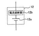
単電池12は、図3に示すように、発電要素12aおよび電流遮断器12bを有する。発電要素12aおよび電流遮断器12bは、単電池12の外装を構成する電池ケースに収容されている。発電要素12aは、充放電を行う要素であり、正極板と、負極板と、正極板および負極板の間に配置されるセパレータとを有する。正極板は、集電板と、集電板の表面に形成された正極活物質層とを有する。負極板は、集電板と、集電板の表面に形成された負極活物質層とを有する。正極活物質層は、正極活物質や導電剤などを含んでおり、負極活物質層は、負極活物質や導電剤などを含んでいる。
The cell 12 includes a power generation element 12a and a current breaker 12b as shown in FIG. The power generation element 12 a and the current breaker 12 b are accommodated in a battery case that constitutes the exterior of the unit cell 12. The power generation element 12a is an element that performs charging and discharging, and includes a positive electrode plate, a negative electrode plate, and a separator disposed between the positive electrode plate and the negative electrode plate. The positive electrode plate includes a current collector plate and a positive electrode active material layer formed on the surface of the current collector plate. The negative electrode plate has a current collector plate and a negative electrode active material layer formed on the surface of the current collector plate. The positive electrode active material layer includes a positive electrode active material and a conductive agent, and the negative electrode active material layer includes a negative electrode active material and a conductive agent.
単電池12としてリチウムイオン二次電池を用いるときには、例えば、正極板の集電板をアルミニウムで形成し、負極板の集電板を銅で形成することができる。また、正極活物質としては、例えば、LiCo1/3Ni1/3Mn1/3O2を用い、負極活物質としては、例えば、カーボンを用いることができる。セパレータ、正極活物質層および負極活物質層には、電解液がしみ込んでいる。電解液を用いる代わりに、正極板および負極板の間に、固体電解質層を配置することもできる。
When a lithium ion secondary battery is used as the single battery 12, for example, the current collector plate of the positive electrode plate can be made of aluminum, and the current collector plate of the negative electrode plate can be made of copper. As the positive electrode active material, for example, LiCo 1/3 Ni 1/3 Mn 1/3 O 2 can be used, and as the negative electrode active material, for example, carbon can be used. An electrolyte solution is infiltrated into the separator, the positive electrode active material layer, and the negative electrode active material layer. Instead of using the electrolytic solution, a solid electrolyte layer may be disposed between the positive electrode plate and the negative electrode plate.
電流遮断器12bは、単電池12の内部における電流経路を遮断するために用いられる。すなわち、電流遮断器12bが作動することにより、単電池12の内部における電流経路が遮断される。電流遮断器12bとしては、例えば、ヒューズ、PTC(Positive Temperature Coefficient)素子又は、電流遮断弁を用いることができる。これらの電流遮断器12bは、個別に用いることもできるし、併用することもできる。
The current breaker 12b is used to cut off the current path inside the unit cell 12. That is, when the current breaker 12b operates, the current path inside the unit cell 12 is cut off. As the current breaker 12b, for example, a fuse, a PTC (Positive Temperature Coefficient) element, or a current cut-off valve can be used. These current breakers 12b can be used individually or in combination.
電流遮断器12bとしてのヒューズは、ヒューズに流れる電流に応じて溶断する。ヒューズを溶断させることにより、単電池12の内部における電流経路を機械的に遮断することができる。これにより、発電要素12aに過大な電流が流れるのを防止して、単電池12(発電要素12a)を保護することができる。電流遮断器12bとしてのヒューズは、電池ケースに収容することもできるし、電池ケースの外部に設けることもできる。電池ケースの外部にヒューズを設ける場合であっても、各単電池12に対してヒューズが設けられ、ヒューズは、各単電池12と直列に接続される。
The fuse as the current breaker 12b is blown according to the current flowing through the fuse. By blowing the fuse, the current path inside the unit cell 12 can be mechanically interrupted. Thereby, it can prevent that an excessive electric current flows into the electric power generation element 12a, and can protect the cell 12 (electric power generation element 12a). The fuse as the current breaker 12b can be accommodated in the battery case or can be provided outside the battery case. Even when a fuse is provided outside the battery case, a fuse is provided for each unit cell 12, and the fuse is connected in series with each unit cell 12.
電流遮断器12bとしてのPTC素子は、単電池12の電流経路に配置されており、PTC素子の温度上昇に応じて抵抗を増加させる。PTC素子に流れる電流が増加すると、ジュール熱によってPTC素子の温度が上昇する。PTC素子の温度上昇に応じて、PTC素子の抵抗が増加することにより、PTC素子において、電流を遮断することができる。これにより、発電要素12aに過大な電流が流れるのを防止して、単電池12(発電要素12a)を保護することができる。
The PTC element as the current breaker 12b is arranged in the current path of the unit cell 12, and increases the resistance according to the temperature rise of the PTC element. When the current flowing through the PTC element increases, the temperature of the PTC element rises due to Joule heat. As the resistance of the PTC element increases as the temperature of the PTC element rises, current can be cut off in the PTC element. Thereby, it can prevent that an excessive electric current flows into the electric power generation element 12a, and can protect the cell 12 (electric power generation element 12a).
電流遮断器12bとしての電流遮断弁は、単電池12の内圧上昇に応じて変形し、発電要素12aとの機械的な接続を断つことにより、単電池12の内部における電流経路を遮断することができる。単電池12の内部は、密閉状態となっており、過充電などによって発電要素12aからガスが発生すると、単電池12の内圧が上昇する。発電要素12aからガスが発生しているときには、単電池12(発電要素12a)は異常状態となる。単電池12の内圧が上昇することに応じて、電流遮断弁を変形させることにより、発電要素12aとの機械的な接続を断つことができる。これにより、異常状態にある発電要素12aに充放電電流が流れるのを阻止し、単電池12(発電要素12a)を保護することができる。
The current cut-off valve as the current breaker 12b is deformed in accordance with the increase in the internal pressure of the unit cell 12, and can cut off the current path inside the unit cell 12 by breaking the mechanical connection with the power generation element 12a. it can. The inside of the unit cell 12 is in a sealed state, and when gas is generated from the power generation element 12a due to overcharging or the like, the internal pressure of the unit cell 12 increases. When gas is generated from the power generation element 12a, the unit cell 12 (power generation element 12a) is in an abnormal state. The mechanical connection with the power generation element 12a can be broken by deforming the current cutoff valve in response to the increase in the internal pressure of the unit cell 12. Thereby, it can block | prevent that charging / discharging electric current flows into the electric power generation element 12a in an abnormal state, and can protect the cell 12 (electric power generation element 12a).
図1に示す監視ユニット20は、各電池ブロック11の電圧を検出し、検出結果をコントローラ40に出力する。電流センサ31は、組電池10に流れる電流値を検出し、検出結果をコントローラ40に出力する。例えば、組電池10を放電しているときには、電流センサ31によって検出された電流値として、正の値を用いることができる。また、組電池10を充電しているときには、電流センサ31によって検出された電流値として、負の値を用いることができる。電流センサ31は、組電池10に流れる電流値を検出できればよく、正極ラインPLではなく、負極ラインNLに設けることもできる。また、複数の電流センサ31を用いることもできる。なお、コストや体格などを考慮すると、本実施例のように、1つの組電池10に対して1つの電流センサ31を設けることが望ましい。
The monitoring unit 20 shown in FIG. 1 detects the voltage of each battery block 11 and outputs the detection result to the controller 40. The current sensor 31 detects the value of the current flowing through the assembled battery 10 and outputs the detection result to the controller 40. For example, when the assembled battery 10 is being discharged, a positive value can be used as the current value detected by the current sensor 31. Further, when the battery pack 10 is being charged, a negative value can be used as the current value detected by the current sensor 31. The current sensor 31 only needs to be able to detect the value of the current flowing through the assembled battery 10 and can be provided not on the positive electrode line PL but on the negative electrode line NL. A plurality of current sensors 31 can also be used. In consideration of cost, physique, etc., it is desirable to provide one current sensor 31 for one assembled battery 10 as in this embodiment.
コントローラ40は、メモリ41を内蔵しており、メモリ41は、コントローラ40を動作させるためのプログラムや、特定の情報を記憶している。メモリ41は、コントローラ40の外部に設けることもできる。
The controller 40 has a built-in memory 41, and the memory 41 stores a program for operating the controller 40 and specific information. The memory 41 can also be provided outside the controller 40.
次に、本実施例の電池システムにおける一部の処理について、図4に示すフローチャートを用いて説明する。図4に示す処理は、所定の周期で行われ、コントローラ40によって実行される。図4に示す処理は、各電池ブロック11に対して行われる。
Next, part of the processing in the battery system of the present embodiment will be described with reference to the flowchart shown in FIG. The process shown in FIG. 4 is performed at a predetermined cycle and executed by the controller 40. The process shown in FIG. 4 is performed for each battery block 11.
ステップS101において、コントローラ40は、各電池ブロック11の内部抵抗又は満充電容量を取得する。取得した内部抵抗又は満充電容量に関する情報は、メモリ41に記憶される。電池ブロック11の内部抵抗又は満充電容量を取得する方法としては、公知の方法を適宜用いることができる。
In step S101, the controller 40 acquires the internal resistance or full charge capacity of each battery block 11. Information about the acquired internal resistance or full charge capacity is stored in the memory 41. As a method for obtaining the internal resistance or the full charge capacity of the battery block 11, a known method can be used as appropriate.
電池ブロック11の内部抵抗を取得する方法(一例)について説明する。
A method (an example) of acquiring the internal resistance of the battery block 11 will be described.
まず、電池ブロック11の電流値および電圧値の関係を複数取得する。コントローラ40は、電流センサ31の出力に基づいて、電池ブロック11の電流値を取得することができる。また、コントローラ40は、監視ユニット20の出力に基づいて、電池ブロック11の電圧値を取得することができる。図5に示すように、横軸を電流値とし、縦軸を電圧値とした座標系において、取得した電流値および電圧値の関係をプロットする。そして、プロットされた複数の点に基づいて、近似直線Lを算出する。近似直線Lの傾きが、電池ブロック11の内部抵抗となる。
First, a plurality of relationships between the current value and voltage value of the battery block 11 are acquired. The controller 40 can acquire the current value of the battery block 11 based on the output of the current sensor 31. Further, the controller 40 can acquire the voltage value of the battery block 11 based on the output of the monitoring unit 20. As shown in FIG. 5, the relationship between the acquired current value and voltage value is plotted in a coordinate system in which the horizontal axis is the current value and the vertical axis is the voltage value. Then, an approximate straight line L is calculated based on the plotted points. The slope of the approximate straight line L becomes the internal resistance of the battery block 11.
ここで、電池ブロック11の電流値および電圧値を取得するときには、電池ブロック11のSOC(State of Charge)が略一定であることが好ましい。SOCとは、電池ブロック11の満充電容量に対する、現在の充電容量の割合を示す。電池ブロック11のSOCが略一定であるときには、電流値および電圧値の関係が、図5に示すように直線関係となる。電流値および電圧値を取得している間に、電池ブロック11のSOCが変化してしまうと、電流値および電圧値の関係が直線関係にはならず、直線Lの傾き、言い換えれば、電池ブロック11の内部抵抗を特定し難くなってしまう。
Here, when the current value and the voltage value of the battery block 11 are acquired, it is preferable that the SOC (State of Charge) of the battery block 11 is substantially constant. The SOC indicates the ratio of the current charge capacity to the full charge capacity of the battery block 11. When the SOC of the battery block 11 is substantially constant, the relationship between the current value and the voltage value is a linear relationship as shown in FIG. If the SOC of the battery block 11 changes while acquiring the current value and the voltage value, the relationship between the current value and the voltage value does not become a linear relationship, but the slope of the straight line L, in other words, the battery block. 11 is difficult to specify the internal resistance.
次に、電池ブロック11の満充電容量を取得する方法(一例)について説明する。
Next, a method (example) of acquiring the full charge capacity of the battery block 11 will be described.
まず、互いに異なるタイミングにおいて、電池ブロック11のSOCを算出(推定)する。ここで、前のタイミングで算出されるSOCを開始SOCといい、後のタイミングで算出されるSOCを終了SOCという。SOCを算出する方法としては、公知の方法を適宜用いることができる。例えば、SOCおよびOCV(Open Circuit Voltage)は、対応関係にあるため、この対応関係を予め特定しておけば、OCVからSOCを特定することができる。
First, the SOC of the battery block 11 is calculated (estimated) at different timings. Here, the SOC calculated at the previous timing is called a start SOC, and the SOC calculated at the later timing is called an end SOC. As a method for calculating the SOC, a known method can be appropriately used. For example, since SOC and OCV (Open Circuit Voltage) have a correspondence relationship, if this correspondence relationship is specified in advance, the SOC can be specified from the OCV.
OCVを算出する方法としては、公知の方法を適宜用いることができる。例えば、組電池10を放置すると、言い換えれば、組電池10の充放電を行わないと、単電池12の分極状態を解消することができる。このため、分極状態が解消されたときの電池ブロック11の電圧を取得すれば、この電圧値をOCVと見なすことができる。具体的には、組電池10を放置した後に電池システムを起動するとき、電池システムを起動した直後において、監視ユニット20によって、電池ブロック11の電圧を検出する。監視ユニット20による検出電圧を、電池ブロック11のOCVと見なすことができる。
As a method for calculating the OCV, a known method can be used as appropriate. For example, if the assembled battery 10 is left as it is, in other words, if the assembled battery 10 is not charged / discharged, the polarization state of the unit cell 12 can be eliminated. For this reason, if the voltage of the battery block 11 when the polarization state is eliminated is obtained, this voltage value can be regarded as OCV. Specifically, when starting the battery system after leaving the assembled battery 10, the voltage of the battery block 11 is detected by the monitoring unit 20 immediately after starting the battery system. The voltage detected by the monitoring unit 20 can be regarded as the OCV of the battery block 11.
一方、電池ブロック11のSOCが、開始SOCから終了SOCに変化するまでの間において、電池ブロック11に流れる電流値を積算して、積算値Ieを算出する。電池ブロック11に流れる電流値は、電流センサ31によって取得することができる。コントローラ40は、下記式(1)に基づいて、電池ブロック11の満充電容量を算出することができる。
On the other hand, the current value flowing through the battery block 11 is integrated until the SOC of the battery block 11 changes from the start SOC to the end SOC to calculate the integrated value Ie. The current value flowing through the battery block 11 can be acquired by the current sensor 31. The controller 40 can calculate the full charge capacity of the battery block 11 based on the following formula (1).
Smax=Ie/|SOC(1)-SOC(2)|×100 ・・・(1)
Smax = Ie / | SOC (1) -SOC (2) | × 100 (1)
式(1)において、Smaxは、電池ブロック11の満充電容量を示し、Ieは、電流積算値を示す。SOC(1)は開始SOCを示し、SOC(2)は終了SOCを示す。
In Equation (1), Smax represents the full charge capacity of the battery block 11, and Ie represents the current integrated value. SOC (1) indicates the start SOC, and SOC (2) indicates the end SOC.
ステップS102において、コントローラ40は、時刻t1,t2のそれぞれにおいて、ステップS101で取得された内部抵抗に基づいて、抵抗変化率を算出する。抵抗変化率は、下記式(2)に基づいて算出することができる。または、コントローラ40は、時刻t1,t2のそれぞれにおいて、ステップS101で取得された満充電容量に基づいて、容量変化率を算出する。容量変化率は、下記式(3)に基づいて算出することができる。
In step S102, the controller 40 calculates a resistance change rate based on the internal resistance acquired in step S101 at each of the times t1 and t2. The resistance change rate can be calculated based on the following formula (2). Alternatively, the controller 40 calculates the capacity change rate based on the full charge capacity acquired in step S101 at each of the times t1 and t2. The capacity change rate can be calculated based on the following formula (3).
Rr=R2/R1 ・・・(2)
Sr=S2/S1 ・・・(3)
Rr = R2 / R1 (2)
Sr = S2 / S1 (3)
式(2)において、Rrは、抵抗変化率を示す。R1は、時刻t1で取得された内部抵抗を示し、R2は、時刻t2で取得された内部抵抗を示す。式(3)において、Srは、容量変化率を示す。S1は、時刻t1で取得された満充電容量を示し、S2は、時刻t2で取得された満充電容量を示す。
In the formula (2), Rr represents a resistance change rate. R1 indicates the internal resistance acquired at time t1, and R2 indicates the internal resistance acquired at time t2. In Expression (3), Sr represents a capacity change rate. S1 indicates the full charge capacity acquired at time t1, and S2 indicates the full charge capacity acquired at time t2.
時刻t1,t2は、互いに異なるタイミングである。時刻t2としては、内部抵抗又は満充電容量を取得したときの今回のタイミングとすることができる。時刻t1としては、内部抵抗又は満充電容量を取得したときの前回のタイミングとすることができる。すなわち、時刻t1は、時刻t2よりも前のタイミングである。
Times t1 and t2 are different timings. The time t2 can be the current timing when the internal resistance or the full charge capacity is acquired. The time t1 can be the previous timing when the internal resistance or the full charge capacity is acquired. That is, time t1 is a timing before time t2.
時刻t1は、時刻t2に対して、直近のタイミングであってもよいし、直近のタイミングよりも前のタイミングであってもよい。時刻t1は、時刻t2よりも前のタイミングであればよく、適宜設定することができる。時刻t1よりも前のタイミングで取得した内部抵抗又は満充電容量に関する情報は、メモリ41から削除することができる。不要な情報を削除することにより、メモリ41の容量を確保することができる。
The time t1 may be the latest timing with respect to the time t2, or may be a timing before the latest timing. The time t1 may be any timing as long as it is before the time t2, and can be set as appropriate. Information about the internal resistance or the full charge capacity acquired at the timing before time t1 can be deleted from the memory 41. By deleting unnecessary information, the capacity of the memory 41 can be secured.
ステップS103において、コントローラ40は、時刻t1,t2の間隔が所定期間T以内であるか否かを判別する。所定期間Tは、電池ブロック11の劣化が進行する速度に基づいて、決定することができる。以下、所定期間Tを決定する方法について説明する。
In step S103, the controller 40 determines whether or not the interval between the times t1 and t2 is within a predetermined period T. The predetermined period T can be determined based on the speed at which the deterioration of the battery block 11 proceeds. Hereinafter, a method for determining the predetermined period T will be described.
電池ブロック11(単電池12)が劣化するときの内部抵抗の変化や、満充電容量の変化は、実験によって予め取得しておくことができる。電池ブロック11の劣化としては、摩耗による劣化を考慮することができる。摩耗劣化とは、電池ブロック11(単電池12)を構成する部材(特に、発電要素12a)が摩耗することによる劣化である。
The change in internal resistance and the change in full charge capacity when the battery block 11 (unit cell 12) deteriorates can be obtained in advance by experiments. As the deterioration of the battery block 11, deterioration due to wear can be considered. The wear deterioration is deterioration caused by wear of members (particularly the power generation element 12a) constituting the battery block 11 (unit cell 12).
電池ブロック11に対して所定の充放電を繰り返す実験などを行うことにより、内部抵抗の経時変化を予め取得することができる。内部抵抗の経時変化は、図6に示す曲線C1として取得することができる。図6に示すように、時間が経過するにつれて、言い換えれば、電池ブロック11の摩耗劣化が進行するにつれて、電池ブロック11の内部抵抗は、上昇することになる。
By conducting an experiment in which the battery block 11 is repeatedly charged / discharged in a predetermined manner, the change in internal resistance with time can be acquired in advance. The change in internal resistance with time can be obtained as a curve C1 shown in FIG. As shown in FIG. 6, the internal resistance of the battery block 11 increases as time passes, in other words, as the wear deterioration of the battery block 11 progresses.
また、電池ブロック11に対して所定の充放電を繰り返す実験などを行うことにより、満充電容量の経時変化を予め取得することができる。満充電容量の経時変化は、図7に示す曲線C2として取得することができる。図7に示すように、時間が経過するにつれて、言い換えれば、電池ブロック11の摩耗劣化が進行するにつれて、電池ブロック11の満充電容量は、低下することになる。
In addition, by performing an experiment in which the battery block 11 is repeatedly charged / discharged in a predetermined manner, a change with time of the full charge capacity can be acquired beforehand. The change with time of the full charge capacity can be acquired as a curve C2 shown in FIG. As shown in FIG. 7, as time elapses, in other words, as the wear deterioration of the battery block 11 progresses, the full charge capacity of the battery block 11 decreases.
電池ブロック11(単電池12)の摩耗劣化だけが発生しているとき、時刻t1,t2のそれぞれで取得された内部抵抗は、図6において、内部抵抗の経時変化を示す曲線C1上に位置することになる。ここで、電流遮断器12bが作動したときには、作動状態にある電流遮断器12bを含む単電池12には電流が流れないことになるため、電流遮断器12bが作動した直後に、電池ブロック11の内部抵抗が上昇する。すなわち、電流遮断器12bが作動したときの電池ブロック11の内部抵抗は、摩耗劣化に相当する内部抵抗よりも高くなる。
When only the wear deterioration of the battery block 11 (unit cell 12) occurs, the internal resistance acquired at each of the times t1 and t2 is located on the curve C1 indicating the change over time of the internal resistance in FIG. It will be. Here, when the current breaker 12b is activated, no current flows through the unit cell 12 including the current breaker 12b in the activated state. Therefore, immediately after the current breaker 12b is activated, Internal resistance increases. That is, the internal resistance of the battery block 11 when the current breaker 12b is activated is higher than the internal resistance corresponding to wear deterioration.
図6に示す曲線C1を用いれば、電池ブロック11の摩耗劣化によって、時刻t1の内部抵抗に対して、内部抵抗が所定量だけ上昇するときの期間を予め特定することができる。この期間よりも短い期間において、時刻t2の内部抵抗が、時刻t1の内部抵抗に対して所定量だけ上昇しているときには、電池ブロック11には、摩耗劣化による内部抵抗の上昇だけでなく、電流遮断器12bの作動に伴う内部抵抗の上昇が発生していると判別することができる。
If the curve C1 shown in FIG. 6 is used, the period when the internal resistance increases by a predetermined amount with respect to the internal resistance at time t1 due to wear deterioration of the battery block 11 can be specified in advance. In a period shorter than this period, when the internal resistance at time t2 is increased by a predetermined amount with respect to the internal resistance at time t1, the battery block 11 has not only increased internal resistance due to wear deterioration but also current. It can be determined that an increase in internal resistance due to the operation of the circuit breaker 12b has occurred.
摩耗劣化では、電池ブロック11の内部抵抗が徐々に上昇するのに対して、電流遮断器12bが作動したときには、電池ブロック11の内部抵抗が急激に上昇する。したがって、摩耗劣化によって電池ブロック11の内部抵抗が所定量だけ上昇するまでの期間よりも十分に短い期間において、電池ブロック11の内部抵抗が所定量だけ上昇したときには、電流遮断器12bが作動していると判別することができる。この時間間隔を監視することにより、電流遮断器12bが作動しているか否かを判別することができる。
In the wear deterioration, the internal resistance of the battery block 11 gradually increases, whereas when the current breaker 12b is activated, the internal resistance of the battery block 11 rapidly increases. Therefore, when the internal resistance of the battery block 11 increases by a predetermined amount in a period sufficiently shorter than the period until the internal resistance of the battery block 11 increases by a predetermined amount due to wear deterioration, the current breaker 12b is activated. Can be determined. By monitoring this time interval, it can be determined whether or not the current breaker 12b is operating.
例えば、摩耗劣化だけが進行したときでは、図6に示す曲線C1に基づいて、時刻t1から半年経過したときに、電池ブロック11の内部抵抗が1.1倍になるとする。ここで、図6に示す時刻t1および時刻t2の間隔が1ヶ月以内であるにもかかわらず、時刻t1および時刻t2の間において、電池ブロック11の内部抵抗が1.1倍になったときには、電流遮断器12bが作動していると判別することができる。
For example, when only wear deterioration has progressed, it is assumed that the internal resistance of the battery block 11 becomes 1.1 times when half a year has elapsed from time t1 based on the curve C1 shown in FIG. Here, when the internal resistance of the battery block 11 becomes 1.1 times between the time t1 and the time t2 even though the interval between the time t1 and the time t2 shown in FIG. 6 is within one month, It can be determined that the current breaker 12b is operating.
一方、電池ブロック11(単電池12)の摩耗劣化だけが発生しているとき、時刻t1,t2のそれぞれで取得された満充電容量は、図7において、満充電容量の経時変化を示す曲線C2上に位置することになる。ここで、電池ブロック11では、複数の単電池12が並列に接続されているため、電池ブロック11の満充電容量は、複数の単電池12における満充電容量の総和となる。
On the other hand, when only the wear deterioration of the battery block 11 (unit cell 12) occurs, the full charge capacity acquired at each of the times t1 and t2 is a curve C2 showing the change over time of the full charge capacity in FIG. Will be located on top. Here, in the battery block 11, since the plurality of single cells 12 are connected in parallel, the full charge capacity of the battery block 11 is the sum of the full charge capacities of the plurality of single cells 12.
電流遮断器12bが作動すると、作動状態にある電流遮断器12bを含む単電池12には、電流が流れなくなるため、電池ブロック11の満充電容量は、電流が流れなくなった単電池12の分だけ低下する。すなわち、電流遮断器12bが作動したときの電池ブロック11の満充電容量は、摩耗劣化に相当する満充電容量よりも低くなる。
When the current breaker 12b is activated, no current flows through the unit cell 12 including the current breaker 12b in the activated state. Therefore, the full charge capacity of the battery block 11 is the amount of the unit cell 12 in which no current flows. descend. That is, the full charge capacity of the battery block 11 when the current breaker 12b is activated is lower than the full charge capacity corresponding to wear deterioration.
ここで、電池ブロック11を構成する単電池12の数が少ないほど、電池ブロック11の満充電容量に対して、各単電池12の満充電容量が占める割合が高くなる。したがって、電池ブロック11を構成する単電池12の数が少ないほど、電池ブロック11において、電流遮断器12bの作動に伴う満充電容量の低下量は増加する。
Here, the smaller the number of the single cells 12 constituting the battery block 11, the higher the ratio of the full charge capacity of each single cell 12 to the full charge capacity of the battery block 11. Therefore, as the number of single cells 12 constituting the battery block 11 is smaller, the amount of decrease in the full charge capacity associated with the operation of the current breaker 12b in the battery block 11 increases.
図7に示す曲線C2を用いれば、電池ブロック11の摩耗劣化によって、時刻t1の満充電容量に対して、満充電容量が所定量だけ低下するときの期間を予め特定することができる。この期間よりも短い期間において、時刻t2の満充電容量が、時刻t1の満充電容量に対して所定量だけ低下しているときには、電池ブロック11には、摩耗劣化による満充電容量の低下だけでなく、電流遮断器12bの作動に伴う満充電容量の低下が発生していると判別することができる。
Using the curve C2 shown in FIG. 7, it is possible to specify in advance a period when the full charge capacity is reduced by a predetermined amount with respect to the full charge capacity at time t1 due to wear deterioration of the battery block 11. In a period shorter than this period, when the full charge capacity at time t2 is reduced by a predetermined amount with respect to the full charge capacity at time t1, the battery block 11 has only a decrease in full charge capacity due to wear deterioration. In other words, it can be determined that the full charge capacity is reduced due to the operation of the current breaker 12b.
摩耗劣化では、電池ブロック11の満充電容量が徐々に低下するのに対して、電流遮断器12bが作動したときには、電池ブロック11の満充電容量が急激に低下する。したがって、摩耗劣化によって電池ブロック11の満充電容量が所定量だけ低下するまでの期間よりも十分に短い期間において、電池ブロック11の満充電容量が所定量だけ低下したときには、電流遮断器12bが作動していると判別することができる。この時間間隔を監視することにより、電流遮断器12bが作動しているか否かを判別することができる。
In the wear deterioration, the full charge capacity of the battery block 11 gradually decreases, whereas when the current breaker 12b is activated, the full charge capacity of the battery block 11 rapidly decreases. Therefore, when the full charge capacity of the battery block 11 decreases by a predetermined amount in a period sufficiently shorter than the period until the full charge capacity of the battery block 11 decreases by a predetermined amount due to wear deterioration, the current breaker 12b is activated. It can be determined that it is. By monitoring this time interval, it can be determined whether or not the current breaker 12b is operating.
例えば、摩耗劣化だけが進行するときでは、図7に示す曲線C2に基づいて、時刻t1から半年経過したときに、電池ブロック11の満充電容量が0.9倍になるとする。ここで、図7に示す時刻t1および時刻t2の間隔が1ヶ月以内であるにもかかわらず、時刻t1および時刻t2の間において、電池ブロック11の満充電容量が0.9倍になったときには、電流遮断器12bが作動していると判別することができる。
For example, when only wear deterioration progresses, it is assumed that the full charge capacity of the battery block 11 becomes 0.9 times when half a year has elapsed from time t1 based on the curve C2 shown in FIG. Here, when the full charge capacity of the battery block 11 becomes 0.9 times between the time t1 and the time t2 even though the interval between the time t1 and the time t2 shown in FIG. 7 is within one month. It can be determined that the current breaker 12b is operating.
ステップS103において、時刻t1,t2の間隔が所定期間Tよりも長いときには、図4に示す処理を終了する。所定期間Tとは、ステップS102で取得した抵抗変化率又は容量変化率が、摩耗劣化だけによって発生するときの期間である。具体的には、所定期間Tは、時刻t1から時刻t2までの間の内部抵抗の上昇率(ステップS102で取得した抵抗変化率)が発生するまでの期間であって、図6に示す曲線C1から特定される期間である。また、所定期間Tは、時刻t1から時刻t2までの間の満充電容量の低下率(ステップS102で取得した容量変化率)が発生するまでの期間であって、図7に示す曲線C2から特定される期間である。
In step S103, when the interval between times t1 and t2 is longer than the predetermined period T, the processing shown in FIG. The predetermined period T is a period when the resistance change rate or the capacity change rate acquired in step S102 is generated only by wear deterioration. Specifically, the predetermined period T is a period until the rate of increase in internal resistance (the resistance change rate acquired in step S102) from time t1 to time t2 is generated, and the curve C1 shown in FIG. It is a period specified from Further, the predetermined period T is a period until the rate of decrease of the full charge capacity from the time t1 to the time t2 (capacity change rate acquired in step S102) occurs, and is specified from the curve C2 shown in FIG. It is a period.
時刻t1,t2の間隔が所定期間Tよりも長いとき、コントローラ40は、電池ブロック11において、電流遮断器12bが作動していないと判別する。一方、時刻t1,t2の間隔が所定期間T以内であるときには、ステップS104の処理に進む。すなわち、時刻t1,t2の間隔が所定期間T以内であるとき、コントローラ40は、電池ブロック11において、電流遮断器12bが作動していると判別する。
When the interval between the times t1 and t2 is longer than the predetermined period T, the controller 40 determines in the battery block 11 that the current breaker 12b is not operating. On the other hand, when the interval between the times t1 and t2 is within the predetermined period T, the process proceeds to step S104. That is, when the interval between the times t1 and t2 is within the predetermined period T, the controller 40 determines that the current breaker 12b is operating in the battery block 11.
ステップS104において、コントローラ40は、ステップS102で算出した抵抗変化率Rr又は容量変化率Srに基づいて、作動状態にある電流遮断器12bの数(遮断数という)を特定する。
In step S104, the controller 40 specifies the number of current breakers 12b in the operating state (referred to as the number of breaks) based on the resistance change rate Rr or the capacity change rate Sr calculated in step S102.
電流遮断器12bが作動する前の電池ブロック11の内部抵抗をRaとし、電流遮断器12bが作動した後の電池ブロック11の内部抵抗をRbとすると、内部抵抗Ra,Rbは、下記式(4)に示す関係を有する。一方、電流遮断器12bが作動する前の電池ブロック11の満充電容量をSaとし、電流遮断器12bが作動した後の電池ブロック11の満充電容量をSbとすると、満充電容量Sa,Sbは、下記式(5)に示す関係を有する。
Assuming that the internal resistance of the battery block 11 before the current breaker 12b is activated is Ra and the internal resistance of the battery block 11 after the current breaker 12b is activated is Rb, the internal resistances Ra and Rb are expressed by the following formula (4 ). On the other hand, when the full charge capacity of the battery block 11 before the current breaker 12b is operated is Sa and the full charge capacity of the battery block 11 after the current breaker 12b is operated is Sb, the full charge capacities Sa and Sb are And has the relationship shown in the following formula (5).
Rb=Ra×N/(N-m) ・・・(4)
Sb=Sa×(N-m)/N ・・・(5)
Rb = Ra × N / (N−m) (4)
Sb = Sa × (N−m) / N (5)
式(4)および式(5)において、Nは、各電池ブロック11を構成する単電池12の数、言い換えれば、並列に接続された単電池12の数を示す。mは、各電池ブロック11において、作動状態にある電流遮断器12bの総数(遮断数)を示す。電流遮断器12bは、各単電池12に設けられているため、遮断数mは、作動状態にある電流遮断器12bを有する単電池12の総数となる。電池ブロック11において、すべての電流遮断器12bが作動していないときには、遮断数mが0となる。
In the formulas (4) and (5), N represents the number of the unit cells 12 constituting each battery block 11, in other words, the number of the unit cells 12 connected in parallel. m indicates the total number (the number of interruptions) of the current breakers 12b in the operating state in each battery block 11. Since the current breaker 12b is provided in each unit cell 12, the number of breaks m is the total number of the unit cells 12 having the current breaker 12b in the operating state. In the battery block 11, when all the current breakers 12b are not operating, the breaking number m is zero.
電流遮断器12bが作動すると、作動状態にある電流遮断器12bの数に応じて、電池ブロック11の内部抵抗が上昇する。すなわち、式(4)に示すように、電流遮断器12bが作動した後の電池ブロック11の内部抵抗Rbは、電流遮断器12bが作動する前の電池ブロック11の内部抵抗Raに対して、N/(N-m)倍となる。「N/(N-m)」の値は、1よりも大きい値となるため、内部抵抗Rbは、内部抵抗Raよりも高くなる。
When the current breaker 12b is activated, the internal resistance of the battery block 11 is increased according to the number of current breakers 12b in the activated state. That is, as shown in Expression (4), the internal resistance Rb of the battery block 11 after the current breaker 12b is activated is N with respect to the internal resistance Ra of the battery block 11 before the current breaker 12b is activated. / (Nm) times. Since the value of “N / (N−m)” is a value larger than 1, the internal resistance Rb is higher than the internal resistance Ra.
一方、電流遮断器12bが作動すると、作動状態にある電流遮断器12bの数に応じて、電池ブロック11の満充電容量が低下する。すなわち、式(5)に示すように、電流遮断器12bが作動した後の電池ブロック11の満充電容量Sbは、電流遮断器12bが作動する前の電池ブロック11の満充電容量Saに対して、(N-m)/N倍となる。「(N-m)/N」の値は、1よりも小さい値となるため、満充電容量Sbは、満充電容量Saよりも低くなる。
On the other hand, when the current breaker 12b is activated, the full charge capacity of the battery block 11 is reduced according to the number of current breakers 12b in the activated state. That is, as shown in Expression (5), the full charge capacity Sb of the battery block 11 after the current breaker 12b is activated is compared with the full charge capacity Sa of the battery block 11 before the current breaker 12b is activated. , (N−m) / N times. Since the value of “(N−m) / N” is a value smaller than 1, the full charge capacity Sb is lower than the full charge capacity Sa.
式(4)および式(5)を変形すると、式(6)および式(7)で表すことができる。
When Expression (4) and Expression (5) are modified, they can be expressed by Expression (6) and Expression (7).
Rb/Ra=N/(N-m) ・・・(6)
Sb/Sa=(N-m)/N ・・・(7)
Rb / Ra = N / (N−m) (6)
Sb / Sa = (N−m) / N (7)
式(6)に示す「Rb/Ra」の値は、式(2)に示す「Rr(=R1/R2」)の値に相当する。すなわち、ステップS102で算出した抵抗変化率Rrが、「N/(N-m)」の値と等しくなる。したがって、抵抗変化率Rrおよび数(既定値)Nに基づいて、遮断数mを算出することができる。
The value of “Rb / Ra” shown in Equation (6) corresponds to the value of “Rr (= R1 / R2”) shown in Equation (2). That is, the resistance change rate Rr calculated in step S102 is equal to the value “N / (N−m)”. Therefore, based on the resistance change rate Rr and the number (predetermined value) N, the cutoff number m can be calculated.
ここで、抵抗変化率Rrに誤差が含まれているときには、誤差を許容する範囲(許容値α1)を予め定めておき、許容値α1を考慮して、遮断数mを算出することができる。具体的には、数mを変更しながら、「N/(N-m)」の値を算出する。そして、許容範囲内に、抵抗変化率Rrが含まれているか否かを判別する。ここで、算出値「N/(N-m)」に許容値α1を加算した値を、許容範囲の上限値とし、算出値「N/(N-m)」から許容値α1を減算した値を、許容範囲の下限値とすることができる。
Here, when an error is included in the resistance change rate Rr, a range (allowable value α1) in which the error is allowed is determined in advance, and the cutoff number m can be calculated in consideration of the allowable value α1. Specifically, the value “N / (N−m)” is calculated while changing the number m. Then, it is determined whether or not the resistance change rate Rr is included in the allowable range. Here, the value obtained by adding the allowable value α1 to the calculated value “N / (N−m)” is set as the upper limit value of the allowable range, and the value obtained by subtracting the allowable value α1 from the calculated value “N / (N−m)” Can be set as the lower limit of the allowable range.
抵抗変化率Rrが許容範囲に含まれているときには、このときの数mを、作動状態にある電流遮断器12bの総数とすることができる。許容値α1は、数Nに応じて変更することができる。すなわち、数Nが多くなるほど、許容値α1を小さくすることができる。言い換えれば、数Nが少なくなるほど、許容値α1を大きくすることができる。
When the resistance change rate Rr is included in the allowable range, the number m at this time can be the total number of the current breakers 12b in the operating state. The allowable value α1 can be changed according to the number N. That is, the allowable value α1 can be reduced as the number N increases. In other words, the allowable value α1 can be increased as the number N decreases.
数Nは、組電池10を構成するときに予め設定されるため、数Nに基づいて、許容値α1を予め決めておけばよい。
Since the number N is set in advance when the assembled battery 10 is configured, the allowable value α1 may be determined in advance based on the number N.
式(7)に示す「Cb/Ca」の値は、式(3)に示す「Sr(=S1/S2」)の値に相当する。すなわち、ステップS102で算出した容量変化率Srが、「(N-m)/N」の値と等しくなる。したがって、容量変化率Srおよび数(既定値)Nに基づいて、遮断数mを算出することができる。
The value of “Cb / Ca” shown in Equation (7) corresponds to the value of “Sr (= S1 / S2”) shown in Equation (3). That is, the capacity change rate Sr calculated in step S102 is equal to the value “(N−m) / N”. Therefore, based on the capacity change rate Sr and the number (predetermined value) N, the cutoff number m can be calculated.
ここで、容量変化率Srに誤差が含まれているときには、誤差を許容する範囲(許容値α2)を予め定めておき、許容値α2を考慮して、遮断数mを算出することができる。具体的には、数mを変更しながら、「(N-m)/N」の値を算出する。そして、許容範囲内に、容量変化率Srが含まれているか否かを判別する。ここで、算出値「(N-m)/N」に許容値α2を加算した値を、許容範囲の上限値とし、算出値「(N-m)/N」から許容値α2を減算した値を、許容範囲の下限値とすることができる。
Here, when an error is included in the capacity change rate Sr, a range (allowable value α2) in which the error is allowed is determined in advance, and the cutoff number m can be calculated in consideration of the allowable value α2. Specifically, the value “(N−m) / N” is calculated while changing the number m. Then, it is determined whether or not the capacity change rate Sr is included in the allowable range. Here, the value obtained by adding the allowable value α2 to the calculated value “(N−m) / N” is used as the upper limit value of the allowable range, and the value obtained by subtracting the allowable value α2 from the calculated value “(N−m) / N” Can be set as the lower limit of the allowable range.
容量変化率Srが許容範囲内に含まれているときには、このときの数mを、作動状態にある電流遮断器12bの総数とすることができる。許容値α2は、数Nに応じて変更することができる。すなわち、数Nが多くなるほど、許容値α2を小さくすることができる。言い換えれば、数Nが少なくなるほど、許容値α2を大きくすることができる。
When the capacity change rate Sr is included in the allowable range, the number m at this time can be the total number of the current breakers 12b in the operating state. The allowable value α2 can be changed according to the number N. That is, the allowable value α2 can be reduced as the number N increases. In other words, the allowable value α2 can be increased as the number N decreases.
数Nは、組電池10を構成するときに予め設定されるため、数Nに基づいて、許容値α2を予め決めておけばよい。
Since the number N is preset when the assembled battery 10 is configured, the allowable value α2 may be determined in advance based on the number N.
図4に示す処理においては、抵抗変化率Rrおよび容量変化率Srのいずれか一方を考慮することもできるし、抵抗変化率Rrおよび容量変化率Srの両者を考慮することもできる。
In the processing shown in FIG. 4, either the resistance change rate Rr or the capacitance change rate Sr can be considered, or both the resistance change rate Rr and the capacitance change rate Sr can be considered.
本実施例では、時刻t1,t2で取得した内部抵抗R1,R2から抵抗変化率Rrを算出し、抵抗変化率Rrから遮断数mを算出しているが、これに限るものではない。
In this embodiment, the resistance change rate Rr is calculated from the internal resistances R1 and R2 acquired at the times t1 and t2, and the cutoff number m is calculated from the resistance change rate Rr. However, the present invention is not limited to this.
例えば、所定時刻で取得した電池ブロック11の内部抵抗と、予め求められた内部抵抗の経時変化(図6の曲線C1)から特定される所定時刻での内部抵抗とから、抵抗変化率Rrを算出することができる。すなわち、ステップS101の処理において、電池ブロック11の内部抵抗を取得するとともに、ステップS101の処理を行ったときと同じ時刻における内部抵抗を、図6の曲線C1から特定する。
For example, the resistance change rate Rr is calculated from the internal resistance of the battery block 11 acquired at a predetermined time and the internal resistance at a predetermined time specified from the change over time of the internal resistance obtained in advance (curve C1 in FIG. 6). can do. That is, in the process of step S101, the internal resistance of the battery block 11 is acquired, and the internal resistance at the same time as when the process of step S101 is performed is specified from the curve C1 in FIG.
抵抗変化率Rrを算出するとき、式(2)に示すR1として、図6の曲線C1から特定される内部抵抗を用いることができる。また、式(2)に示すR2として、ステップS101の処理で取得した内部抵抗を用いることができる。抵抗変化率Rrを算出できれば、本実施例で説明した方法によって、遮断数mを算出することができる。
When calculating the resistance change rate Rr, the internal resistance specified from the curve C1 in FIG. 6 can be used as R1 shown in Expression (2). Moreover, the internal resistance acquired by the process of step S101 can be used as R2 shown in Formula (2). If the resistance change rate Rr can be calculated, the cutoff number m can be calculated by the method described in this embodiment.
また、本実施例では、時刻t1,t2で取得した満充電容量S1,S2から容量変化率Srを算出し、容量変化率Srから遮断数mを算出しているが、これに限るものではない。
In this embodiment, the capacity change rate Sr is calculated from the full charge capacities S1 and S2 acquired at the times t1 and t2, and the cutoff number m is calculated from the capacity change rate Sr. However, the present invention is not limited to this. .
例えば、所定時刻で取得した電池ブロック11の満充電容量と、予め求められた満充電容量の経時変化(図7の曲線C2)から特定される所定時刻での満充電容量とから、容量変化率Srを算出することができる。すなわち、ステップS101の処理において、電池ブロック11の満充電容量を取得するとともに、ステップS101の処理を行ったときと同じ時刻における満充電容量を、図7の曲線C2から特定する。
For example, the capacity change rate from the full charge capacity of the battery block 11 acquired at a predetermined time and the full charge capacity at a predetermined time specified from a change with time of the full charge capacity obtained in advance (curve C2 in FIG. 7). Sr can be calculated. That is, in the process of step S101, the full charge capacity of the battery block 11 is acquired, and the full charge capacity at the same time as when the process of step S101 is performed is specified from the curve C2 in FIG.
容量変化率Srを算出するとき、式(3)に示すS1として、図7の曲線C2から特定される満充電容量を用いることができる。また、式(3)に示すS2として、ステップS101の処理で取得した満充電容量を用いることができる。容量変化率Srを算出できれば、本実施例で説明した方法によって、遮断数mを算出することができる。
When calculating the capacity change rate Sr, the full charge capacity specified from the curve C2 of FIG. 7 can be used as S1 shown in Expression (3). Moreover, as S2 shown in Formula (3), the full charge capacity acquired by the process of step S101 can be used. If the capacity change rate Sr can be calculated, the blocking number m can be calculated by the method described in this embodiment.
一方、本実施例では、時刻t1,t2の間隔が所定期間T以内であるか否かを判別することにより、電流遮断器12bが作動しているか否かを判別しているが、これに限るものではない。
On the other hand, in this embodiment, it is determined whether or not the current breaker 12b is operating by determining whether or not the interval between the times t1 and t2 is within the predetermined period T. However, the present invention is not limited to this. It is not a thing.
例えば、電池ブロック11の内部抵抗を取得し、取得した内部抵抗が、電池ブロック11の摩耗劣化に相当する内部抵抗よりも高くなったときに、電流遮断器12bが作動状態であることを判別することができる。言い換えれば、取得した内部抵抗が、摩耗劣化に相当する内部抵抗の曲線(図6に示す曲線C1)に対して、抵抗が高い側にずれているときには、電流遮断器12bが作動状態であることを判別することができる。
For example, the internal resistance of the battery block 11 is acquired, and when the acquired internal resistance is higher than the internal resistance corresponding to the wear deterioration of the battery block 11, it is determined that the current breaker 12b is in an operating state. be able to. In other words, when the acquired internal resistance is shifted to the higher resistance side with respect to the curve of internal resistance corresponding to wear deterioration (curve C1 shown in FIG. 6), the current breaker 12b is in an operating state. Can be determined.
また、電池ブロック11の満充電容量を取得し、取得した満充電容量が、電池ブロック11の摩耗劣化に相当する満充電容量よりも低くなったときに、電流遮断器12bが作動状態であることを判別することができる。言い換えれば、取得した満充電容量が、摩耗劣化に相当する満充電容量の曲線(図7に示す曲線C2)に対して、容量が低い側にずれているときには、電流遮断器12bが作動状態であることを判別することができる。
Moreover, when the full charge capacity of the battery block 11 is acquired and the acquired full charge capacity becomes lower than the full charge capacity corresponding to the wear deterioration of the battery block 11, the current breaker 12b is in an operating state. Can be determined. In other words, when the acquired full charge capacity is deviated toward the lower side of the full charge capacity curve (curve C2 shown in FIG. 7) corresponding to wear deterioration, the current breaker 12b is in the operating state. It can be determined that there is.
遮断数mを特定した後において、コントローラ40は、遮断数mに基づいて、組電池10の充放電を制御することができる。
After specifying the shut-off number m, the controller 40 can control charging / discharging of the assembled battery 10 based on the shut-off number m.
電池ブロック11において、電流遮断器12bが作動すると、作動状態にある電流遮断器12bを有する単電池12には、電流が流れないことになる。また、作動状態にある電流遮断器12bを有する単電池12と並列に接続された他の単電池12には、作動状態にある電流遮断器12bを有する単電池12に流れる予定である電流が流れてしまう。ここで、組電池10(電池ブロック11)に流れる電流値Isを制限しないときには、他の単電池12に流れる電流値は、Is/(N-m)となる。「N-m」の値は、「N」の値よりも小さいため、他の単電池12に流れる電流値は上昇してしまう。
When the current breaker 12b is activated in the battery block 11, no current flows through the unit cell 12 having the current breaker 12b in the activated state. Moreover, the current which is going to flow through the single cell 12 which has the current circuit breaker 12b in an operation state flows into the other single cell 12 connected in parallel with the single cell 12 which has the current circuit breaker 12b in the operation state. End up. Here, when the current value Is flowing through the assembled battery 10 (battery block 11) is not limited, the current value flowing through the other single battery 12 is Is / (N−m). Since the value of “N−m” is smaller than the value of “N”, the value of the current flowing through the other unit cells 12 increases.
単電池12に流れる電流値が上昇すると、言い換えれば、単電池12に対する電流負荷が増加すると、ハイレート劣化が発生しやすくなるおそれがある。ハイレート劣化とは、ハイレートで充電又は放電が行われることにより、単電池12の電解液中における塩濃度が一方(正極側又は負極側)に偏ってしまうことによる劣化である。塩濃度が一方に偏ってしまうと、正極および負極の間において、イオンの移動が抑制されるため、単電池12の入出力性能が低下してしまい、単電池12の劣化となる。
When the value of the current flowing through the unit cell 12 increases, in other words, when the current load on the unit cell 12 increases, there is a risk that high-rate deterioration is likely to occur. High-rate deterioration is deterioration due to the fact that the salt concentration in the electrolyte solution of the unit cell 12 is biased to one side (positive electrode side or negative electrode side) when charging or discharging is performed at a high rate. If the salt concentration is biased to one side, the movement of ions between the positive electrode and the negative electrode is suppressed, so that the input / output performance of the unit cell 12 is deteriorated and the unit cell 12 is deteriorated.
また、単電池12として、リチウムイオン二次電池を用いたときには、リチウムが析出しやすくなるおそれがある。リチウムが析出すると、正極および負極の間で移動するリチウムイオンが減少し、結果として、単電池12の満充電容量が低下してしまう。さらに、単電池12に流れる電流値が上昇すると、電流遮断器12bが作動しやすくなってしまうおそれがある。
Further, when a lithium ion secondary battery is used as the single battery 12, lithium may be easily deposited. When lithium is deposited, lithium ions moving between the positive electrode and the negative electrode are decreased, and as a result, the full charge capacity of the unit cell 12 is decreased. Furthermore, when the value of the current flowing through the unit cell 12 increases, the current breaker 12b may be easily activated.
コントローラ40は、遮断数mを特定したとき、この遮断数mに基づいて、組電池10の充放電を制御する電流指令値を決定することができる。具体的には、コントローラ40は、電流指令値として、遮断数mが増加することに応じて、組電池10の充放電電流を低下させることができる。コントローラ40は、下記式(8)に基づいて、電流指令値を設定することができる。
The controller 40 can determine a current command value for controlling charging / discharging of the assembled battery 10 based on the number m of interruptions when the number m of interruptions is specified. Specifically, the controller 40 can reduce the charge / discharge current of the assembled battery 10 as the current command value increases as the number of interruptions m increases. The controller 40 can set the current command value based on the following formula (8).
Is(2)=Is(1)×(N-m)/N ・・・(8)
Is (2) = Is (1) × (N−m) / N (8)
式(8)において、Is(1)は、電流遮断器12bが作動する前の電流指令値であり、Is(2)は、電流遮断器12bが作動した後の電流指令値である。式(8)から分かるように、「(N-m)/N」の値は、1よりも小さい値であるため、電流指令値Is(2)は、電流指令値Is(1)よりも小さくなる。
In Expression (8), Is (1) is a current command value before the current breaker 12b is activated, and Is (2) is a current command value after the current breaker 12b is activated. As can be seen from the equation (8), since the value of “(N−m) / N” is a value smaller than 1, the current command value Is (2) is smaller than the current command value Is (1). Become.
コントローラ40は、電流指令値Is(2)に基づいて、組電池10の充放電を制御することができる。具体的には、コントローラ40は、電流指令値Is(2)に基づいて、組電池10の充電を許容する上限電力を低下させたり、組電池10の放電を許容する上限電力を低下させたりする。上限電力を低下させるときには、低下させる前の上限電力に対して、「(N-m)/N」の値を乗算することができる。組電池10の充放電を許容する上限電力を低下させることにより、組電池10(単電池12)に流れる電流値を制限することができる。
The controller 40 can control charging / discharging of the assembled battery 10 based on the current command value Is (2). Specifically, the controller 40 reduces the upper limit power that allows charging of the assembled battery 10 or decreases the upper limit power that allows discharging of the assembled battery 10 based on the current command value Is (2). . When lowering the upper limit power, the upper limit power before being lowered can be multiplied by a value of “(N−m) / N”. By reducing the upper limit power that allows charging / discharging of the assembled battery 10, the value of the current flowing through the assembled battery 10 (unit cell 12) can be limited.
遮断数mが「N」であるときには、電池ブロック11を構成する、すべての単電池12において、電流遮断器12bが作動していることになり、組電池10に電流を流すことができなくなる。このため、遮断数mが「N」であるとき、コントローラ40は、組電池10の充放電を行わせないようにすることができる。具体的には、コントローラ40は、組電池10の充放電を許容する上限電力を0[kW]に設定することができる。また、コントローラ40は、システムメインリレーSMR-B,SMR-G,SMR-Pをオフにすることができる。
When the interruption number m is “N”, the current breaker 12b is in operation in all the unit cells 12 constituting the battery block 11, and the current cannot be supplied to the assembled battery 10. For this reason, when the shut-off number m is “N”, the controller 40 can prevent the assembled battery 10 from being charged / discharged. Specifically, the controller 40 can set the upper limit power that allows charging and discharging of the assembled battery 10 to 0 [kW]. Further, the controller 40 can turn off the system main relays SMR-B, SMR-G, and SMR-P.
なお、遮断数mが「N」に近づいたときに、組電池10の充放電を行わせないようにすることができる。ここで、組電池10の充放電を行わせないときの遮断数mの数は、車両の走行を確保する観点などに基づいて、適宜設定することができる。
It should be noted that the battery pack 10 can be prevented from being charged / discharged when the shut-off number m approaches “N”. Here, the number of shut-off numbers m when charging / discharging of the assembled battery 10 is not performed can be appropriately set based on the viewpoint of ensuring the traveling of the vehicle.
組電池10の充放電制御は、図1に示す電池システムが起動しているときだけでなく、外部電源の電力を組電池10に供給しているときや、組電池10の電力を外部機器に供給しているときにも行うことができる。外部電源とは、車両の外部に設けられた電源であり、外部電源としては、例えば、商用電源を用いることができる。外部機器とは、車両の外部に配置された電子機器であって、組電池10からの電力を受けて動作する電子機器である。外部機器としては、例えば、家電製品を用いることができる。
The charge / discharge control of the assembled battery 10 is performed not only when the battery system shown in FIG. 1 is activated, but also when the power of the external power source is supplied to the assembled battery 10 or when the power of the assembled battery 10 is supplied to an external device. It can also be done while feeding. The external power source is a power source provided outside the vehicle, and for example, a commercial power source can be used as the external power source. The external device is an electronic device arranged outside the vehicle, and is an electronic device that operates by receiving electric power from the assembled battery 10. As the external device, for example, a home appliance can be used.
外部電源の電力を組電池10に供給するときには、充電器を用いることができる。充電器は、外部電源からの交流電力を直流電力に変換し、直流電力を組電池10に供給することができる。充電器は、車両に搭載することもできるし、車両の外部において、車両とは別に設けることもできる。また、外部電源の電圧および組電池10の電圧を考慮して、充電器は、電圧値を変換することができる。コントローラ40は、充電器の動作を制御することにより、組電池10の電流値(充電電流)を低下させることができる。
When supplying power from the external power source to the assembled battery 10, a charger can be used. The charger can convert AC power from an external power source into DC power and supply the DC power to the assembled battery 10. The charger can be mounted on the vehicle or can be provided outside the vehicle separately from the vehicle. Further, the charger can convert the voltage value in consideration of the voltage of the external power supply and the voltage of the assembled battery 10. The controller 40 can reduce the current value (charging current) of the assembled battery 10 by controlling the operation of the charger.
組電池10の電力を外部機器に供給するときには、給電装置を用いることができる。給電装置は、組電池10からの直流電力を交流電力に変換し、交流電力を外部機器に供給することができる。また、組電池10の電圧および外部機器の動作電圧を考慮して、給電装置は、電圧値を変換することができる。コントローラ40は、給電装置の動作を制御することにより、組電池10の電流値(放電電流)を低下させることができる。
When supplying the power of the assembled battery 10 to an external device, a power feeding device can be used. The power feeding device can convert DC power from the assembled battery 10 into AC power and supply the AC power to an external device. Further, the power supply device can convert the voltage value in consideration of the voltage of the assembled battery 10 and the operating voltage of the external device. The controller 40 can reduce the current value (discharge current) of the assembled battery 10 by controlling the operation of the power supply apparatus.
遮断数mに応じて、組電池10に流れる電流値を制限することにより、単電池12に対する電流負荷が上昇してしまうのを抑制することができる。また、作動していない電流遮断器12bに流れる電流値も制限することができ、電流遮断器12bが作動しやすくなってしまうのを抑制することができる。
By restricting the value of the current flowing through the assembled battery 10 according to the number of interruptions m, it is possible to suppress an increase in the current load on the unit cell 12. Moreover, the electric current value which flows into the electric current breaker 12b which is not act | operating can also be restrict | limited, and it can suppress that the electric current breaker 12b becomes easy to operate | move.
本実施例では、遮断数mに応じて、組電池10の充放電を制御することができるため、組電池10の充放電制御を効率良く行うことができる。電流遮断器12bの作動状態を検出するだけでは、組電池10の充放電が過度に制限されてしまうことがある。これに対して、遮断数mを把握することにより、遮断数mに応じて、組電池10の充放電を制限することができ、組電池10の充放電が過度に制限されてしまうのを抑制することができる。
In this embodiment, since charging / discharging of the assembled battery 10 can be controlled according to the number of interruptions m, charging / discharging control of the assembled battery 10 can be performed efficiently. The charging / discharging of the assembled battery 10 may be excessively limited only by detecting the operating state of the current breaker 12b. On the other hand, by grasping the number of interruptions m, charging / discharging of the assembled battery 10 can be restricted according to the number of interruptions m, and charging / discharging of the assembled battery 10 is prevented from being excessively restricted. can do.