WO2013111475A1 - 自動車の車体前部構造 - Google Patents
自動車の車体前部構造 Download PDFInfo
- Publication number
- WO2013111475A1 WO2013111475A1 PCT/JP2012/082519 JP2012082519W WO2013111475A1 WO 2013111475 A1 WO2013111475 A1 WO 2013111475A1 JP 2012082519 W JP2012082519 W JP 2012082519W WO 2013111475 A1 WO2013111475 A1 WO 2013111475A1
- Authority
- WO
- WIPO (PCT)
- Prior art keywords
- subframe
- frame
- rear end
- main body
- extension
- Prior art date
Links
Images


Classifications
-
- B—PERFORMING OPERATIONS; TRANSPORTING
- B62—LAND VEHICLES FOR TRAVELLING OTHERWISE THAN ON RAILS
- B62D—MOTOR VEHICLES; TRAILERS
- B62D21/00—Understructures, i.e. chassis frame on which a vehicle body may be mounted
- B62D21/15—Understructures, i.e. chassis frame on which a vehicle body may be mounted having impact absorbing means, e.g. a frame designed to permanently or temporarily change shape or dimension upon impact with another body
- B62D21/152—Front or rear frames
- B62D21/155—Sub-frames or underguards
-
- B—PERFORMING OPERATIONS; TRANSPORTING
- B60—VEHICLES IN GENERAL
- B60G—VEHICLE SUSPENSION ARRANGEMENTS
- B60G7/00—Pivoted suspension arms; Accessories thereof
- B60G7/02—Attaching arms to sprung part of vehicle
-
- B—PERFORMING OPERATIONS; TRANSPORTING
- B62—LAND VEHICLES FOR TRAVELLING OTHERWISE THAN ON RAILS
- B62D—MOTOR VEHICLES; TRAILERS
- B62D21/00—Understructures, i.e. chassis frame on which a vehicle body may be mounted
- B62D21/11—Understructures, i.e. chassis frame on which a vehicle body may be mounted with resilient means for suspension, e.g. of wheels or engine; sub-frames for mounting engine or suspensions
-
- B—PERFORMING OPERATIONS; TRANSPORTING
- B62—LAND VEHICLES FOR TRAVELLING OTHERWISE THAN ON RAILS
- B62D—MOTOR VEHICLES; TRAILERS
- B62D25/00—Superstructure or monocoque structure sub-units; Parts or details thereof not otherwise provided for
- B62D25/08—Front or rear portions
- B62D25/082—Engine compartments
-
- B—PERFORMING OPERATIONS; TRANSPORTING
- B60—VEHICLES IN GENERAL
- B60G—VEHICLE SUSPENSION ARRANGEMENTS
- B60G2204/00—Indexing codes related to suspensions per se or to auxiliary parts
- B60G2204/10—Mounting of suspension elements
- B60G2204/12—Mounting of springs or dampers
- B60G2204/122—Mounting of torsion springs
- B60G2204/1222—Middle mounts of stabiliser on vehicle body or chassis
-
- B—PERFORMING OPERATIONS; TRANSPORTING
- B60—VEHICLES IN GENERAL
- B60G—VEHICLE SUSPENSION ARRANGEMENTS
- B60G2204/00—Indexing codes related to suspensions per se or to auxiliary parts
- B60G2204/10—Mounting of suspension elements
- B60G2204/14—Mounting of suspension arms
- B60G2204/143—Mounting of suspension arms on the vehicle body or chassis
-
- B—PERFORMING OPERATIONS; TRANSPORTING
- B60—VEHICLES IN GENERAL
- B60G—VEHICLE SUSPENSION ARRANGEMENTS
- B60G2204/00—Indexing codes related to suspensions per se or to auxiliary parts
- B60G2204/10—Mounting of suspension elements
- B60G2204/15—Mounting of subframes
Definitions
- the present invention relates to a vehicle body front structure.
- This application claims priority based on Japanese Patent Application No. 2012-013085 filed on January 25, 2012 and Japanese Patent Application No. 2012-025027 filed on February 08, 2012. , The contents of which are incorporated herein.
- a subframe that supports suspension parts and the like is provided at the front of the vehicle body, and this subframe is composed of a subframe main body and an extension arm that extends forward from the left and right of the front end of the subframe main body.
- the joint rigidity between the subframe main body and the extension arm is reinforced to transmit the front impact load to the rear floor (see Patent Document 1).
- the subframe is made of a rigid aluminum alloy and a front impact load acts on the suspension arm supported by this subframe, the fragile part in front of the suspension arm rear end fastening part at the rear end of the subframe will be destroyed. Some devices absorb the collision energy (see Patent Document 2).
- an object of the aspect of the present invention is to provide a vehicle body front structure that can reduce weight, improve rigidity, and absorb more collision energy.
- an aspect of the present invention is also to provide a vehicle body front structure that can absorb more energy while suppressing an increase in weight, and can easily set the timing of energy absorption at the time of a collision.
- One aspect according to the present invention is a sub-support that supports suspension parts and in-vehicle parts across the front side frame disposed along the longitudinal direction of the vehicle body on the left and right sides of the front part of the vehicle body and the front part of the vehicle body floor.
- a frame is supported at least at a front end and a rear end; the subframe is fixed to the subframe main body formed of a light alloy casting that supports the suspension component and the vehicle-mounted component at the rear portion, and the subframe main body.
- a pair of left and right extension arms extending forward of the subframe main body and press-molded with a light alloy or steel; an input at the time of a vehicle front collision at the rear of the extension arm and in the vicinity of the subframe main body
- a fragile starting point portion is provided as a starting point that bends downward at a midway portion in the front-rear direction of the subframe due to a load.
- the sub-frame body includes an intermediate fastening portion fixed to a front side frame at a front end portion, and the intermediate fastening portion and the front side frame are fastened by a fastener, When the intermediate fastening portion receives a load downward in either the intermediate fastening portion insertion hole of the fastener provided in the front side frame or the insertion hole of the fastener provided in the intermediate fastening portion.
- a notch for detachment of the fastener that is broken and allows the intermediate fastening portion to move downward may be provided.
- the upper surface of the subframe main body is between the intermediate fastening portion of the subframe main body and the rear end portion of the subframe main body.
- An insertion recess is formed through which the stabilizer, which is a suspension component, is inserted in the vehicle width direction.
- the power steering device is fixed to the upper portion of the subframe body, and the steering gear box of the power steering device closes the opening of the insertion recess. It may be provided at a position where
- the subframe main body is formed in a trapezoidal shape, and the pair of left and right extension arms are arranged in a divergent shape that increases in width toward the front,
- the rear end portion of the sub-frame main body may be connected to a floor center frame attached to the vehicle body floor.
- the rear end portion of the extension arm is fixed to the subframe main body by three fasteners that are vertically inserted and arranged in a triangular shape. May be.
- the rear end portion of the extension arm sandwiches a front end support portion of a lower arm provided at the front end portion of the subframe body from above and below.
- the extension arm may extend forward along the bottom surface of the subframe body.
- each extension arm may be connected to a lower corner portion of a front bulkhead disposed in the front portion of the vehicle body.
- the rear end portion is provided with a fastening portion with respect to the front portion of the vehicle body floor, and rearward in a range from the fastening portion to the vicinity of the heel position of a passenger in a driving posture.
- the end extension may extend.
- a floor tunnel portion is formed at the vehicle width direction center portion of the vehicle body floor, and floor center frames extending in the front-rear direction are provided on both sides of the floor tunnel portion.
- a front end extension is provided at the front end of the vehicle, and the fastening portion of the subframe is fixed to the front end extension of the floor center frame, and the vehicle-mounted component supported by the subframe in front of the front end extension. May be arranged.
- the front end extension of the floor center frame may include a recess for receiving the rear end extension of the subframe.
- the front end portion of the subframe may be located at a position higher than the weakening origin portion of the subframe.
- the rear end extension portion of the subframe may have strength or rigidity equal to or greater than that of the rear portion of the weak start point portion of the subframe.
- the periphery of the fastening portion of the subframe may be reinforced.
- the sub-frame is provided with an intermediate fastening portion with the front side frame at a rear portion of the weakening origin portion, and the intermediate fastening portion has a downward load. There may be provided a separation starting point portion that separates upon receipt.
- the subframe bends downward at the weakening origin portion of the extension arm that is a midway portion in the front-rear direction.
- the suspension component and the vehicle-mounted component supported by the subframe can be displaced downward. Therefore, the suspension parts and the vehicle-mounted parts can be retracted outside the range of the crash stroke of the front side frame, and a large deformation stroke of the vehicle body can be secured to sufficiently absorb the collision energy.
- the sub-frame main body formed with the casting of a light alloy is provided, the weight can be reduced while increasing the support rigidity of the suspension parts and the running stability.
- the pair of left and right extension arms press-molded with a light alloy or steel is provided, energy absorption at the time of the vehicle front collision can be performed by bending deformation of the extension arm at the time of vehicle front collision.
- the intermediate fastening portion of the subframe main body of the subframe faces downward.
- the opening of the insertion recess of the stabilizer that is a suspension component provided in the subframe body is closed by the steering gear box of the power steering device, so that the power steering device is Because it is attached to the upper part of the main body, the steering gear box prevents the insertion recesses from closing in the direction of closing the insertion recesses of the subframe body, which has high rigidity but is molded with light metal casting and is easy to break. This can be prevented.
- the impact load at the time of the front collision of the vehicle can be distributed to the vehicle body floor via the extension arm and the subframe main body and the floor center frame.
- the three fasteners are attached to the subframe main body.
- the extension arm that is prevented from rotating does not rotate in the horizontal direction, and can bend and bend downward from the fragile starting point of the extension arm.
- the rigidity of the front bulkhead can be increased by the subframe.
- the subframe bends downward at the fragile starting point portion, and the rear end extension portion of the subframe is The load acts so as to pull out the fastening portion at the rear end portion of the subframe downward with the end as the center. Therefore, when the fastening part at the rear end of the sub-frame is fixed with a bolt or the like, the bolt acts so that the front part of the vehicle body floor is broken and pulled out in a timely manner to absorb collision energy. In addition, the vehicle body floor can be prevented from being deformed upward.
- the suspension parts and in-vehicle parts supported by the subframe are displaced downward, so the suspension parts and in-vehicle parts are retracted outside the range of the front side frame crash stroke.
- a large deformation stroke of the vehicle body that is, a buckling stroke of the front side frame can be ensured to sufficiently absorb the collision energy.
- the collision energy from the fastening portion of the subframe can be distributed to the floor center frame having high strength and rigidity.
- the rear end extension of the rear end of the subframe can be supported by the front end extension of the floor center frame with high strength and rigidity.
- the in-vehicle components supported by the subframe in the vicinity of the panel are largely retracted downward to ensure a crash stroke of the front side frame, and the front side frame can be prevented from bending and the collision energy absorption amount from being reduced.
- the deformed portion of the front end extension of the floor center frame can be adjusted.
- the vehicle body floor upper raised position near the foot of the vehicle can be set to a position that has a small influence on the occupant.
- the weak starting point of the subframe can be easily bent downward.
- the rear end extension of the subframe is not deformed, and the subframe can be reliably rotated around the rear end of the rear end extension. Accordingly, a fastener such as a bolt of the fastening portion at the rear end portion of the subframe can be reliably pulled out by the lever principle.
- the support rigidity of the subframe can be improved, and when the fastening portion of the subframe is fixed with a bolt or the like, the bolt can be easily detached.
- the suspension component can be supported rearward from the fragile starting point portion of the subframe, so that the front portion of the vehicle body can be shortened and reduced in size. Further, the movement of the subframe turning around the rear end of the rear end extension is not hindered by the separation starting point.
- FIG. 1 It is the perspective view which looked at the vehicle body front part of the car of the 1st embodiment concerning this invention from the lower side. It is a principal part expansion perspective view of FIG. It is the bottom view which looked at the vehicle body front part from the lower side. It is the perspective view which looked at the vehicle body front from diagonally right above. It is the perspective view which looked at the vehicle body front left side from the lower part. It is the perspective view which looked at the vehicle body front part from the left outer side diagonally downward. It is a partially cutaway sectional view showing a front end support part of the lower arm. It is the partially notched perspective view which looked at the attachment site
- FIG. 10 is a cross-sectional view taken along line AA in FIG. 9. It is the perspective view which looked at the state which attached the lower arm from diagonally lower left. It is a principal part bottom view of the state which attached the lower arm. It is the perspective view which looked at the vicinity of the rear-end extension part from the bottom. It is the perspective view which looked at the fastening part from the vehicle interior. It is sectional drawing which follows the BB line of FIG. It is CC sectional drawing of FIG. It is sectional drawing of the sub-frame main body vicinity. It is a partially cutaway perspective view showing an arrangement state of the electric power steering device.
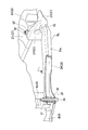
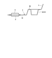
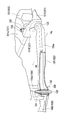
- FIG. 1 It is side surface explanatory drawing of a vehicle body front part. It is side surface explanatory drawing which shows a collision state. It is the perspective view which looked at the vehicle body front part of the motor vehicle of 2nd Embodiment which concerns on this invention from the lower side. It is a principal part expansion perspective view of FIG. It is the bottom view which looked at the vehicle body front part from the lower side. It is the perspective view which looked at the vehicle body front from diagonally right above. It is the perspective view which looked at the vehicle body front left side from the lower part. It is the perspective view which looked at the vehicle body front part from the left outer side diagonally downward. It is the perspective view which looked at the front part of the vehicle body from diagonally forward and lower right.
- FIG. 30 is a cross-sectional view taken along line AA of FIG. 29. It is the perspective view which looked at the state which attached the lower arm from diagonally lower left. It is a principal part bottom view of the state which attached the lower arm. It is the perspective view which looked at the vicinity of the rear-end extension part from the bottom. It is the partially cutaway perspective view which looked at the fastening part from the vehicle interior.
- FIG. 35 is a sectional view taken along line BB in FIG. 34. It is CC sectional drawing of FIG. It is a sectional side view of the rear part attachment part of a sub-frame main body. It is side surface explanatory drawing which shows a collision state.
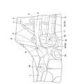
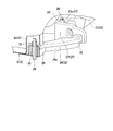
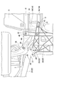
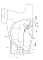
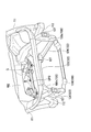
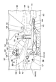
- FIG. 1 is a perspective view of a front part of a vehicle body of an automobile as viewed from below.
- the rear end portion of the dashboard panel 2 is connected to the front end portion of the front floor panel 1 as shown in the front structure of the vehicle body.
- the dashboard panel 2 has a rear end portion that is flat like the front floor panel 1, and the front side rises obliquely forward to separate the vehicle compartment and the engine compartment.
- the flat part of the dashboard panel 2 and the part that starts to rise in front are also configured as a vehicle body floor together with the front floor panel 1.
- the front floor panel 1 is formed with a floor tunnel portion 3 that bulges toward the vehicle interior along the front-rear direction at the center in the vehicle width direction.
- the floor tunnel portion 3 extends toward the rear end portion of the dashboard panel 2 and is connected to a notch portion at the rear end portion of the dashboard panel 2.
- the floor tunnel part 3 (same for the dashboard panel 2) is not formed so as to be lowered from the top to the height of the front floor panel 1, but a slightly lower part is formed lower than the top part, and then the front It continues to the flat part of the floor panel 1 (see FIG. 16).
- the front side frame rear end 6 is joined to the lower surface of the dashboard panel 2 so as to overlap the front end of the floor frame 5 from below.
- the front side frame 7 is joined to the front end of the front side frame rear end 6 along the longitudinal direction of the vehicle body at the position slightly higher than the flat portion of the front floor panel 1 as a frame member of the engine room. Yes.
- a rectangular frame-shaped front bulkhead 8 is attached to the left and right side stays 8s (see FIG. 4) extending vertically at the front ends of the pair of left and right front side frames 7.
- An outrigger 9 is connected between the front side frame rear end 6 and the front end of the side sill 4, and a wheel house 10 is connected to the front end of the dashboard panel 2 located on the front side of the outrigger 9.
- a wheel house upper member 11 is joined to the upper side of the wheel house 10
- a floor center frame 13 and 13 having a hat-shaped cross section that extends along the vehicle body longitudinal direction on both sides of the floor tunnel portion 3 on the lower surface of the front floor panel 1 and forms a closed cross-section structure portion on the lower surface of the front floor panel 1. Is attached.
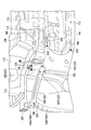
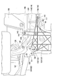
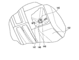
- FIG. 2 is an enlarged perspective view of a main part of FIG. 1 and shows the front left side of the front floor panel 1 enlarged from below.
- a front side frame rear end 6 is a hat-shaped cross-sectional member, and forms a closed cross-sectional structure below the joint portion between the front floor panel 1 and the dashboard panel 2, and the rear end is a floor frame.
- the front end of the front side frame 7 is connected to the rear end of the front side frame 7.
- the front side frame 7 having a closed cross-section structure and the floor frame 5 (shown by a wavy line) forming a closed cross-section structure portion on the front floor panel 1 are connected by the front side frame rear end 6 by the closed cross-section structure portion.
- the front end of the floor frame 5 and the rear end of the front side frame rear end 6 have portions that overlap each other with the front floor panel 1 in between, and the portions that overlap each other gradually increase in cross-sectional area toward the front end. Is formed so as to be small, and is joined to the front and back of the front floor panel 1.
- Outriggers 9 are superposed on the outside of the front side frame rear end 6 in the vehicle width direction from the lower side (upper side in FIG. 2) across the bottom wall portion of each front side frame rear end 6 and each side sill 4.
- the outrigger 9 is joined to the lower surface of each side sill 4 so as to straddle the boundary portion between the front floor panel 1 and the dashboard panel 2 at the outer portion in the vehicle width direction.
- An L-shaped front end extension 14 is joined to the front end of each floor center frame 13 from the lower side (upper side in FIG. 2) across the front floor panel 1 and the dashboard panel 2.
- the front end extension 14 is formed into a hat-shaped cross-sectional shape and is superposed on the floor center frame 13 to form a closed cross-section structure portion, and the rear portion 14r is bent outward and continuously forms a closed cross-section structure portion. It is comprised with the front part connection part 14f to do.
- the front connecting portion 14f extends outward in the vehicle width direction from the front end of the rear portion 14r, and the outer side portion in the width direction of the peripheral flange portion is joined to the inner side wall of the front side frame rear end 6.
- the floor center frame 13 and the front side frame 7 are connected by the closed cross-section structure portion by the front end extension portion 14 provided with the front connection portion 14f.
- the front connecting portion 14f includes a subframe rear end mounting seat 15 facing downward on the front end side.
- Bolt holes 16 are formed in the subframe rear end mounting seat 15.
- the subframe rear end mounting seat 15 is provided at a position (a position higher from the ground) lower than the height of the floor center frame 13 in FIG.
- a recess 17 is formed behind the subframe rear end mounting seat 15 to prevent interference with the rear end of the subframe body 23 of the subframe 22.
- a subframe intermediate coupling hole 18 is formed at the rear end portion of the front side frame 7, and a rear arm support bracket outer mounting hole 19 is formed at the front end portion of the front side frame rear end 6.
- the dashboard panel 2 has a steering shaft insertion hole 20 formed in front of the front end extension 14.
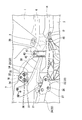
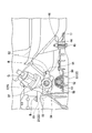
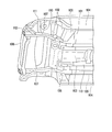
- FIGS. 3 to 5 show a state where the subframe is attached
- FIG. 3 is a bottom view of the front part of the vehicle body as seen from below
- FIG. It is the perspective view which looked at the front left side from the lower part.
- suspension parts including an unillustrated lower arm, tires, etc. and an electric power steering device EPS (described later) are provided across the front side frames 7 and 7 and the front portion of the front floor panel 1.
- the supporting subframe 22 is supported at the front end portion, the rear end portion, and the front-rear direction center portion. Specifically, the subframe extends across the corner portions at the lower ends of the front bulkhead 8 attached to the front side frames 7 and 7 and the front end extension 14 at the front end of the floor center frame 13 attached to the front floor panel 1. 22 is fixed.
- the sub-frame 22 includes a sub-frame main body 23 cast from an aluminum alloy, and a pair of left and right extension arms 24 and 24 that are extended from the both sides of the front end of the sub-frame main body 23 to the front side and are press-formed with a light alloy or steel.
- the electric power steering device EPS is fixed by bolts B at three positions in the vehicle width direction on the upper surface of the subframe 22, that is, the subframe main body 23 as shown in FIG. Of these three places, the front side is two places on both sides in the vehicle width direction, and the rear side is one place in the center in the vehicle width direction.
- a steering gear box G is provided on the left side of the electric power steering device EPS, and the steering gear box G is disposed close to the lower side of the steering shaft insertion hole 20.
- the sub-frame main body 23 includes a rear edge that is curved to the front side, left and right side edges that open outward and extend linearly, and a front edge that extends linearly in the vehicle width direction when viewed from the top. It is a substantially trapezoidal member.
- the subframe body 23 has a flat upper surface, and includes a plurality of intersecting vertical ribs (see FIGS. 11 and 12) on the lower surface to increase rigidity, and upper attachments extending upward at both ends of the front portion of the subframe body 23.
- An arm portion 25 is provided.
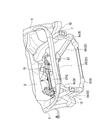
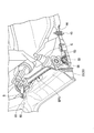
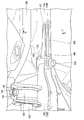
- FIG. 6 is a perspective view of the front part of the vehicle body seen from diagonally below the left outer side
- FIG. 7 is a partially cutaway sectional view showing the front end support part of the lower arm
- FIG. 9 is a partially cutaway perspective view of the attachment portion of the extension arm as viewed from the left side and slightly obliquely forward.
- the extension arms 24, 24 are provided at the extension arm main body 24a, the rear end attaching portion 27 provided at the rear end of the extension arm main body 24a, and the front end of the extension arm main body 24a.
- the front end mounting portion 29 is provided.
- the rear end mounting portion 27 includes a mounting plate 27l that supports the front corner portion of the subframe main body 23 from the lower side, an upper upper mounting piece 27u, and a continuous front wall 27f.
- the mounting plate 27l is fastened and fixed to a screw hole (a boss shape is integrally formed) of the subframe body 23 with three fastening bolts 26, 26, 26 inserted so as to form a triangle from the lower side to the upper side.
- the upper mounting piece 27u is fastened and fixed by a nut 26 'through one fastening bolt 26 from the lower side.
- the mounting plate 27l has a larger area than the upper mounting piece 27u and extends rearward, and the upper mounting piece 27u is formed inside the upper portion of the rear end mounting portion 27.
- the upper portion of the rear end mounting portion 27 extends outward from the upper mounting piece 27u, and then the height gradually decreases (see FIG. 8) and finally decreases downward.
- a rear end portion of the extension arm main body 24a is connected to the outside of the front wall 27f of the rear end attachment portion 27 by MIG welding.
- the front arm attachment portions 29 of the extension arms 24, 24 are disposed at a position higher than the rear end attachment portion 27 (at the ground level) (see FIG. 19), and the lower corners of the front bulkhead 8 are disposed at the front end portion of the extension arm body 24a.
- This is fastened and fixed by a fixing bolt 28 to the joint portion of the portion, that is, the side stay 8s and the lower cross 8l.
- the front end mounting portion 29 is fastened and fixed by a fixing bolt 28 and a nut 31 from below via a built-in collar 30.
- the lower end piece of the front end mounting portion 29 is fastened to the lower surface of the lower cross 8 l of the front bulkhead 8.
- the extension arm main body 24a is formed in a closed cross-sectional structure by inserting a lower member 24al having an open cross-sectional shape opened from the lower side into an upper member 24au having an open cross-sectional shape opened at the lower side (see FIG. 10). ).
- a recessed portion 32 is formed slightly forward from the attachment portion of the rear end attachment portion 27 to the front wall 27f.
- the recessed portion 32 is a constricted portion as viewed from the side, and usually does not bend at all. However, the recessed portion 32 is lowered at a midway portion in the front-rear direction of the subframe 22 by a predetermined input load at the time of a vehicle frontal collision. It becomes the starting point to bend towards.
- the dent-shaped portion 32 constitutes the extension arm main body 24a, that is, a weak starting point portion where the extension arm 24 bends downward.
- the recessed portion 32 is formed at a position lower than the front end mounting portion 29 of the extension arm 24.
- the subframe 22 includes an upper mounting arm portion 25 at the rear portion of the recessed portion 32.
- the recess-shaped portion 32 is formed by reducing the diameter of both the upper member 24au and the lower member 24al. In addition, you may provide the recessed shape part 32 only in the upper member 24au.
- a connection bracket 33 (a part of the front side frame 7) is attached to the upper end portion of the upper mounting arm portion 25 of the subframe main body 23 by two fixing bolts 34, 34 from the side to the outside. It is fixed.
- the connecting bracket 33 is fastened and fixed to the subframe intermediate coupling hole 18 (see FIG. 2) at the rear end portion of the front side frame 7 by fastening bolts 35 inserted upward.
- the bolt insertion hole 36 of the connection bracket 33 through which the fixing bolts 34 and 34 are inserted is provided with a notch 37 for removal in which a part of the lower side is notched.
- connection bracket 33 remains in the front side frame 7.
- the fixing bolts 34, 34 are allowed to fall downward from the detachment notch 37 and detach from the connection bracket 33 to allow the upper mounting arm portion 25, that is, the subframe main body 23 to be displaced downward. Therefore, the size of the notch 37 for separation is determined in accordance with the load that acts when the subframe body 23 is bent.
- reference numeral 38 denotes a lower arm that is a suspension component.
- the lower arm 38 is supported by the front side frame 7 and the subframe main body 23 through a support bracket 39 so that the rear end thereof can swing about the front-rear direction, and the front end is provided at the front end of the subframe main body 23.
- the support 21 is supported so as to be swingable about the front-rear direction.
- the support bracket 39 is configured to surround a bearing member (not shown) in a U shape, and the support bolt 40 inserted from below into the insertion hole 42 at the outer end is attached to the rear end support bracket outside.
- the hole 19 (see FIG. 2) is fastened and fixed, and the inner end is fastened and fixed to the mounting portion of the subframe main body 23 by a fixing bolt 41.
- the insertion hole 42 on the outer side of the support bracket 39 is provided with a detachment notch 43 that functions as a detachment starting point part in which a part of the outer side is notched.
- FIG. 13 On both sides of the rear portion of the subframe main body 23, the front portion of the front floor panel 1, that is, the subframe rear end mounting seat 15 of the front end extension portion 14 of the floor center frame 13 connected to the front floor panel 1.
- Fastening portions 44 are provided.
- the fastening portion 44 is a cylindrical portion.
- a fastening bolt 45 is inserted into the fastening portion 44 from below and is fastened and fixed to a bolt hole 16 (see FIGS. 2 and 15) provided in the subframe rear end mounting seat 15.
- FIG. 14 is a partially cutaway perspective view of the fastening portion 44 as viewed from the vehicle interior.
- FIG. 15 is a sectional view taken along the line BB of FIG. 14 (excluding the fastening bolt 45). As shown in FIGS.
- the fastening bolt 45 inserted through the fastening portion 44 is fastened to a weld nut 46 welded to the back surface of the subframe rear end mounting seat 15.
- a reinforcing plate 47 is overlapped and welded around the weld nut 46 so as to surround the weld nut 46 with a diameter larger than the outer shape of the weld nut 46.
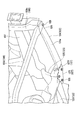
- FIG. 16 is a sectional view taken along the line CC of FIG.
- bulging portions 50 that are slightly lower than the top portion but higher than the flat portion 51 are formed on both sides of the floor tunnel portion 3.
- the front end extension 14 of the floor center frame 13 is joined to the back side of the bulging portion 50.
- the front end extension 14 and the rear terminal do not protrude below the flat part 51 of the dashboard panel 2.
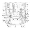
- FIG. 17 is a cross-sectional view of the vicinity of the subframe main body
- FIG. 18 is a perspective view showing an arrangement state of the electric power steering device
- FIG. As shown in FIGS. 17 to 19, an insertion recess 53 into which a stabilizer 52 as a suspension component is inserted in the vehicle width direction is formed between the upper mounting arm portion 25 and the fastening portion 44 of the subframe body 23. ing.
- the insertion recess 53 is formed such that the lower part is formed in an arc shape in cross section and the front and rear walls are opened toward the upper side.
- the steering gear box G of the electric power steering apparatus EPS attached to the upper surface of the subframe main body 23 is provided at a position where the opening 54 of the insertion recess 53 is closed.
- the electric power steering apparatus EPS is provided with front mounting arms 61 and 61 at the left and right front parts, respectively, as described in FIG. 4, and the front mounting arms 61 and 61 are formed by two bolts B and B.
- the rear mounting arm 62 is provided at the rear portion at the center in the vehicle width direction, and the rear mounting arm 62 is rearward of the insertion concave portion 53 by a single bolt B.
- the rear mounting arm 62 is fixed to the front mounting seats 55, 55 of the insertion concave portion 53.
- the mounting seat 55 is fixed.
- the mounting seats 55, 55 of the sub-frame main body 23 that receives the front mounting arm 61 and the rear mounting arm 62 that are fixed by these bolts B are provided at the front and rear so as to straddle the insertion recess 53.
- the steering gear box G is a heavy member including a torque sensor and a motor, and a rack gear 56 is provided to extend right and left immediately above the opening 54.
- a boot 57 is provided at the tip of the rack gear 56 as shown in FIG.
- a protected tie rod 58 is attached.
- the tie rod 58 is linked to a knuckle arm (not shown).
- a stabilizer 52 attached across the left and right lower arms 38 is inserted into the lower portion of the insertion recess 53 of the subframe body 23, and both ends of the stabilizer 52 are connected to the stabilizer support seats 59 of the subframe body 23 via brackets 60. And is rotatably supported.
- the front impact load when an impact load is applied at the time of a vehicle frontal collision, the front impact load is strengthened from the pair of extension arms 24, 24 arranged in a divergent shape so as to open toward the front, via the subframe body 23.
- the floor center frames 13 and 13 having high rigidity are dispersed.
- a forward impact load (arrow F) of a certain level or more acts and a backward load acts on the lower portion of the front bulkhead 8
- the extension arms 24 and 24 of the subframe 22 are recessed.
- the lower arm 38 which is a suspension component supported by the subframe 22, and the electric power steering device EPS, which is an in-vehicle component, can be displaced downward (arrow D). it can.
- the lower arm 38 and the electric power steering device EPS are retracted to the lower side outside the range of the crash stroke of the front side frames 7 and 7, and a large deformation stroke of the vehicle body can be secured to sufficiently absorb the collision energy. Therefore, the steering gear box G of the electric power steering device EPS does not move rearward to deform the dashboard panel 2.
- the sub-frame 22 includes the sub-frame main body 23 formed of a light alloy casting, it is possible to reduce the weight while increasing the supporting rigidity of the suspension parts such as the lower arm 38 and the running stability. Since the subframe 22 includes a pair of left and right extension arms 24, 24 that are press-formed with light alloy or steel, the energy at the time of the vehicle frontal collision is also caused by the bending deformation of the extension arms 24, 24 at the time of the vehicle frontal collision. Absorption can be performed.
- the upper mounting arm portions 25 and 25 of the subframe main body 23 of the subframe 22 are used. Receives a force on the lower side, and the notch 37 for detachment of the bolt insertion hole 36 of the connecting bracket 33 that fastens the upper mounting arm portions 25, 25 of the subframe main body 23 and the front side frames 7, 7 is broken. (See FIG. 11), the connecting brackets 33 and the upper mounting arm portions 25, 25 are separated. As a result, the upper mounting arm portion 25 of the subframe main body 23 is detached from the front side frames 7 and 7, and bending deformation starting from the recessed shape portion 32 of the extension arm 24 of the subframe 22 is allowed.
- the detachment notch 43 is also provided in the insertion hole 42 of the support bolt 40 in the support bracket 39 of the lower arm 38. 11 (see FIG. 11), the support bracket 39 of the lower arm 38 can be displaced downward similarly to the subframe main body 23, and the movement of the subframe main body 23 is not hindered.
- the opening 54 of the insertion recess 53 of the stabilizer 52 which is a suspension component provided in the subframe body 23, is closed by the steering gear box G of the power steering device EPS, so that the power steering device EPS is connected to the subframe body. Since it is attached to the upper part of 23, the crack which originates in the insertion recessed part 53 of the sub-frame main body 23 which is molded with a light metal casting and is easy to break is closed in the direction in which the insertion recessed part 53 is closed by the steering gear box G. This can be prevented by preventing the deformation of.
- the insertion recess 53 provided for inserting the stabilizer 52, which is a suspension component, in the vehicle width direction may be deformed in the closing direction due to concentration of stress with respect to the load from the front side. Since G closes this, the opening 54 of the insertion recess 53 can be closed, so that a closed cross-sectional structure is formed, stress is not concentrated, and cracking does not occur.
- the extension arms 24, 24 are fixed so that the subframe main body 23 is sandwiched from above and below by the rear end mounting portion 27 and the front side is pressed, and the mounting plate 27l is fastened by the fastening bolts 26 at three triangular points. Even if the extension arms 24 and 24 of the 22 are arranged so as to open toward the front in a divergent shape, the extension arms 24 and 24 do not rotate in the horizontal direction (outward) with respect to the subframe body 23, and the front side When the impact load is applied, the extension arms 24, 24 can be surely bent downward in the recessed portion 32.
- the extension arms 24, 24 sandwich the front end support portion 21 of the lower arm 38 provided at the front end portion of the subframe body 23 from the upper and lower sides and hold the front side by the rear end mounting portion 27, the impact load that acts at the time of a vehicle front collision Is advantageous in that it can be supported by the support portion 21 at the rear end of the lower arm 38 which is a strong portion.
- extension arm 24 is fixed in a state of extending forward along the bottom surface of the subframe body 23, the center of gravity of the subframe body 23 is higher than the center of gravity of the extension arms 24, 24, so that the front of the vehicle
- the sub-frame main body 23 can apply a moment to rotate the rear part upward than the recessed portion 32 of the extension arms 24, 24 at the time of collision, and the front end mounting portion 29 of the extension arms 24, 24 is
- the extension arms 24 and 24 can be reliably bent downward because they are disposed at a position higher than the attachment portion 27. Further, it is possible to secure a sufficient engine arrangement space above the extension arms 24, 24 of the subframe 22. Since the distal end of the extension arm 24 is connected to the lower end corners of the front bulkhead 8, the rigidity of the front bulkhead 8 can be increased by the subframe 22.
- connection bracket 33 is left on the upper side and the notch 37 for removing the fixing bolt 34 is provided in the bolt insertion hole 36 on the connection bracket 33 side
- the upper mounting arm portion 25 can be moved downward.
- a detachment notch may be provided in the bolt insertion hole of the fixing bolt 34 of the upper mounting arm portion 25 so that the detachment notch of the upper mounting arm portion 25 is broken.
- a rivet or the like can be used instead of the fastening bolt 26.
- FIG. 21 is a perspective view of the front part of the vehicle body of the automobile as viewed from below.
- the rear end portion of the dashboard panel 102 is connected to the front end portion of the front floor panel 101.
- the dashboard panel 102 has a rear end portion that is flat like the front floor panel 101, and a front side that rises obliquely forward and separates the vehicle compartment and the engine room.
- the flat portion of the dashboard panel 102 and the portion that starts to rise forward are also configured as a vehicle body floor together with the front floor panel 101.
- the front floor panel 101 is formed with a floor tunnel portion 103 that bulges toward the vehicle interior along the front-rear direction at the center in the vehicle width direction.
- the floor tunnel portion 103 extends toward the rear end portion of the dashboard panel 102 and is connected to a notch portion at the rear end portion of the dashboard panel 102.
- the floor tunnel 103 (similar to the dashboard panel 102) is not formed so as to be lowered from the top to the height of the front floor panel 101, but is formed to be slightly lower than the top, and then the front It continues to the flat part of the floor panel 101 (see FIG. 36).
- the front side frame rear end 106 is joined to the lower surface of the dashboard panel 102 so as to overlap the front end of the floor frame 105 from below.
- a front side frame 107 is joined to the front end of the front side frame rear end 106 along the longitudinal direction of the vehicle body at the position slightly higher than the flat portion of the front floor panel 101 as a frame member of the engine room. Yes.
- a rectangular frame-shaped front bulkhead 108 is attached to the left and right side stays 108s (see FIG. 24) extending vertically, at the front ends of the pair of left and right front side frames 107.
- An outrigger 109 is connected between the front side frame rear end 106 and the front end portion of the side sill 104, and a wheel house 110 is connected to the front end portion of the dashboard panel 102 located on the front side of the outrigger 109.
- a wheel house upper member 111 is joined to the upper side of the wheel house 110, a front end portion of the wheel house lower extension 112 is joined to a front end portion of the wheel house upper member 111, and a rear end portion of the wheel house lower extension 112 is joined to the front side frame. It is joined to the side portion of 107.
- a floor center frame 113, 113 having a hat-shaped cross section is formed on the lower surface of the front floor panel 101 along the longitudinal direction of the vehicle body on both sides of the floor tunnel portion 103 to form a closed cross-section structure portion on the lower surface of the front floor panel 101. Is attached.
- FIG. 22 is an enlarged perspective view of the main part of FIG. 21, and shows the left front side of the front floor panel 101 enlarged from below.
- a front side frame rear end 106 is a member having a hat-shaped cross section, and forms a closed cross section structure below the joint portion between the front floor panel 101 and the dashboard panel 102, and the rear end portion is a floor frame.
- the front end portion of the front side frame 107 is joined to the front end portion of the front side frame 107.
- the front side frame 107 having a closed cross-section structure and the floor frame 105 (shown by a wavy line) forming the closed cross-section structure portion on the front floor panel 101 are connected by the front side frame rear end 106 by the closed cross-section structure portion. .
- the front end of the floor frame 105 and the rear end of the front side frame rear end 106 have portions that overlap each other with the front floor panel 101 in between.
- the portions that overlap each other gradually increase in cross-sectional area toward the front end. Is formed so as to be small, and is joined to the front and back of the front floor panel 101.
- Outriggers 109 are superposed on the outer side of the front side frame rear end 106 in the vehicle width direction from the lower side (upper side in FIG. 22) across the bottom wall portion of each front side frame rear end 106 and each side sill 104.
- the outrigger 109 is joined to the lower surface of each side sill 104 so as to straddle the boundary portion between the front floor panel 101 and the dashboard panel 102 at the outer portion in the vehicle width direction.
- An L-shaped front end extension 114 is joined to the front end of each floor center frame 113 from the lower side (upper side in FIG. 22) across the front floor panel 101 and the dashboard panel 102.
- the front end extension 114 is formed in a hat-shaped cross-sectional shape and is superposed on the floor center frame 113 to form a closed cross-section structure portion, and the rear portion 114r is bent outward to be connected to form a closed cross-section structure portion.
- a front connecting portion 114f extends outward in the vehicle width direction from the front end of the rear portion 114r, and the widthwise outer side portion of the peripheral flange portion is joined to the inner side wall of the front side frame rear end 106.
- the floor center frame 113 and the front side frame 107 are connected by the closed cross-section structure portion by the front end extension portion 114 provided with the front connection portion 114f.
- the front coupling portion 114f includes a subframe rear end mounting seat 115 facing downward on the front end side.
- the subframe rear end mounting seat 115 is provided at a position lower than the height of the floor center frame 113 in FIG. 22 (a higher position from the ground), and is adjacent to the rear portion of the subframe rear end mounting seat 115.
- a recess 117 is formed on the front side of the front connection part 114f, and the amount of protrusion is suppressed lower than that of the rear side of the front connection part 114f.
- a bolt hole 116 is formed in the subframe rear end mounting seat 115, and a rear end extension 149 (see FIG. 33) of a subframe main body 123 of the subframe 122 described later is received in the recess 117.
- a subframe intermediate coupling hole 118 is formed at the rear end portion of the front side frame 107, and a rear arm support bracket outer mounting hole 119 is formed at the front end portion of the front side frame rear end 106.
- the dashboard panel 102 is formed with a steering shaft insertion hole 120 on the front side of the front end extension 114.
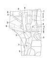
- FIGS. 23 to 25 show a state in which the subframe is attached
- FIG. 23 is a bottom view of the front part of the vehicle body as seen from below
- FIG. It is the perspective view which looked at the front left side from the lower part.
- suspension parts including an unillustrated lower arm, tires, etc., and an electric power steering device EPS (described later) are provided across the front side frames 107, 107 and the front portion of the front floor panel 101.
- the supporting subframe 122 is supported at the front end portion, the rear end portion, and the center portion in the front-rear direction.
- the subframe extends across the corners at both ends of the lower part of the front bulkhead 108 attached to the front side frames 107 and 107 and the front end extension 114 at the front end of the floor center frame 113 attached to the front floor panel 101. 122 is fixed.
- the sub-frame 122 includes a trapezoidal sub-frame main body 123 cast from an aluminum alloy, and a pair of left and right extension arms 124 and 124 extending from the both sides of the front end of the sub-frame main body 123 to the front side in a divergent shape.
- the electric power steering device EPS is fixed by bolts B at three positions in the vehicle width direction on the upper surface of the subframe 122, that is, the subframe main body 123, as shown in FIG.
- a steering gear box G is provided on the left side of the electric power steering apparatus EPS, and the steering gear box G is disposed close to the lower side of the steering shaft insertion hole 120.
- the subframe main body 123 includes a rear edge that curves to the front side when viewed from the top, left and right side edges that open outward and extend linearly, and a front edge that extends linearly in the vehicle width direction. It is a substantially trapezoidal member.
- the subframe main body 123 has a flat upper surface, and includes a plurality of intersecting vertical ribs (see FIGS. 31 and 32) on the lower surface to increase rigidity, and upper attachments extending upward at both ends of the front portion of the subframe main body 123.
- An arm portion 125 is provided.
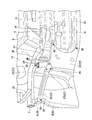
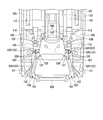
- FIG. 26 is a perspective view of the front part of the vehicle body seen from diagonally below the left outer side
- FIG. 27 is a perspective view of the front part of the vehicle body seen diagonally from the lower right front side
- FIG. A perspective view and FIG. 29 are perspective views of the extension arm attachment site as seen from the left side slightly diagonally forward.
- the extension arms 124 and 124 are provided at the extension arm main body 124a, the rear end attaching portion 127 provided at the rear end of the extension arm main body 124a, and the front end of the extension arm main body 124a.
- the front end mounting portion 129 is provided.
- the rear end attachment portion 127 includes an attachment plate 127l that supports the front corner portion of the subframe main body 123 from below, an upper attachment piece 127u on the upper side, and a front wall 127f that continues these.
- the mounting plate 127l is fastened and fixed to a screw hole (a boss shape is integrally formed) of the subframe main body 123 with three fastening bolts 126, 126, 126 so as to form a triangle from the lower side, and the upper mounting piece 127u is One fastening bolt 126 is inserted from below and is fastened and fixed by a nut 126 ′.
- the extension arms 124 and 124 are fixed by the rear end attaching portion 127 so as to sandwich the sub-frame main body 123 from above and below and press the front side.
- the mounting plate 127l has a larger area than the upper mounting piece 127u and extends rearward, and the upper mounting piece 127u is formed inside the upper portion of the rear end mounting portion 127.
- the upper portion of the rear end attachment portion 127 extends outward from the upper attachment piece 127u, and thereafter the height gradually decreases (see FIG. 28) and finally decreases downward.
- the rear end portion of the extension arm main body 124a is connected to the outside of the front wall 127f of the rear end attaching portion 127.
- the extension arms 124 and 124 are fixed by the rear end attachment portion 127 so as to sandwich the subframe main body 123 from above and below, and the attachment plate 127l is fastened at three triangular points. Even if 124 and 124 are arranged so as to open toward the front in a divergent shape, the extension arms 124 and 124 can be reliably bent downward in a recessed portion 132 described later when an impact load is applied from the front side.
- the front arm attaching portion 129 of the extension arms 124 and 124 is disposed at a position higher than the rear end attaching portion 127 (at the ground level), and a lower corner portion of the front bulkhead 108, that is, a side stay is provided at the front end portion of the extension arm main body 124a. It is fastened and fixed by a fixing bolt 128 to a joint portion between 108s and the lower cross 108l.
- the front end attaching portion 129 is fastened and fixed by a fixing bolt 128 and a nut 131 from below through a built-in collar 130.
- the lower end piece of the front end mounting portion 129 is fastened to the lower surface of the lower cross 108l of the front bulkhead 108.
- the extension arm main body 124a is formed in a closed cross-sectional structure by inserting a lower member 124al having an open cross-sectional shape opened from the lower side into an upper member 124au having an open cross-sectional shape opened at the lower side (see FIG. 30). ).
- a recessed portion 132 is formed slightly forward from the attachment portion of the rear end attachment portion 127 to the front wall 127f.
- This dent-shaped part 132 is a constricted part when viewed from the side, and usually it does not bend at all, but it starts at the middle in the front-rear direction due to a predetermined input load at the time of vehicle front collision. It becomes.
- This dent-shaped portion 132 forms an extension arm main body 124a, that is, a weak starting point portion where the extension arm 124 bends downward.
- the recessed portion 132 is formed at a position lower than the front end mounting portion 129 of the extension arm 124.
- the subframe 122 includes an upper mounting arm portion 125 at a rear portion of the recessed shape portion 132.
- the concave shape portion 132 is formed by reducing the diameters of both the upper member 124au and the lower member 124al.
- connection bracket 133 is fixed to the upper end portion of the upper mounting arm portion 125 of the subframe main body 123 from the side by two fixing bolts 134 and 134.
- the connecting bracket 133 is fastened and fixed to a subframe intermediate coupling hole 118 (see FIG. 22) at the rear end of the front side frame 107 by a fastening bolt 135 inserted upward.
- the bolt insertion hole 136 of the connection bracket 133 through which the fixing bolts 134 and 134 are inserted is provided with a notch 137 for removal in which a part of the lower side is notched.
- the fixing bolts 134, 134 are left in the state where the connection bracket 133 remains on the front side frame 107.
- the upper mounting arm portion 125, that is, the sub-frame main body 123 is allowed to displace downward from the connection bracket 133. Therefore, the size of the notch 137 for separation is determined in accordance with the load acting when the subframe main body 123 is bent.
- reference numeral 138 denotes a lower arm that is a suspension component.
- the lower arm 138 is supported by the front side frame 107 and the subframe main body 123 through the support bracket 139 so that the rear end thereof can swing about the front-rear direction, and the front end is supported by the subframe main body 123 via the support portion 121. Thus, it is supported so that it can swing about the front-rear direction.
- the support bracket 139 is configured to surround a bearing member (not shown) in a U-shape, and the support bolt 140 inserted from below into the insertion hole 142 at the outer end is attached to the outer end of the rear end support bracket. It is fastened and fixed in the hole 119 (see FIG. 22), and the inner end is fastened and fixed to the attachment portion of the subframe main body 123 by the fixing bolt 141.
- the insertion hole 142 on the outer side of the support bracket 139 is provided with a notch 143 for detachment that functions as a detachment starting point part in which a part of the outer side is notched.
- FIG. 33 As shown in FIG. 33, on both sides of the rear portion of the subframe main body 123, the front portion of the front floor panel 101, that is, the subframe rear end mounting seat 115 of the front end extension portion 114 of the floor center frame 113 connected to the front floor panel 101 is provided.
- Fastening portion 144 is provided.
- the fastening portion 144 is a cylindrical portion.
- a fastening bolt 145 is inserted into the fastening portion 144 from below and is fastened and fixed to a bolt hole 116 (see FIGS. 22 and 35) provided in the subframe rear end mounting seat 115.
- FIG. 34 is a partially cutaway perspective view of the fastening portion 144 as viewed from the passenger compartment.
- FIG. 34 is a partially cutaway perspective view of the fastening portion 144 as viewed from the passenger compartment.
- FIG. 35 is a sectional view taken along the line BB of FIG. 34 (excluding the fastening bolt 145).
- the fastening bolt 145 inserted through the fastening portion 144 is fastened to a weld nut 146 welded to the back surface of the subframe rear end mounting seat 115.
- a reinforcing plate 147 is overlapped and welded around the weld nut 146 so as to surround the weld nut 146 with a diameter larger than the outer shape of the weld nut 146.
- a hole 148 is formed in the reinforcing plate 147 so as to escape around the weld nut 146. Therefore, the periphery of the subframe rear end mounting seat 115 is reinforced by the reinforcing plate 147, but the portion itself to which the weld nut 146 is attached is not reinforced, so that the fastening bolt 145 is pulled downward. Then, the fastening bolt 145 breaks the subframe rear end mounting seat 115 together with the weld nut 146 and is easily pulled out from the subframe rear end mounting seat 115.
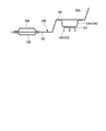
- FIG. 36 is a cross-sectional view taken along the line CC of FIG. 33
- FIG. 37 is a side cross-sectional view of the rear mounting portion of the subframe main body 123.
- the fastening portion 144 of the subframe main body 123 is formed with a rear end extension portion 149 that extends rearward in a range from the fastening portion 144 to the vicinity of the heel position of the occupant in the driving posture (see FIG. 37).
- the rear end extension 149 is adapted to be accommodated in a recess 117 provided on the front side of the front connection part 114 f of the front end extension 114.
- the dashboard panel 102 is formed with bulging portions 150 that are slightly lower than the top portion but higher than the flat portion 151 on both sides of the floor tunnel portion 103.
- the front end extension 114 of the floor center frame 113 is joined to the back side of the bulging portion 150, and the rear end extension 149 of the subframe main body 123 is accommodated in the recess 117 formed on the front side of the rear portion 114r of the front end extension 114.
- the front end extension 114 and the rear end extension 149 do not protrude below the flat portion 151 of the dashboard panel 102.
- the rear end extension 149 of the subframe main body 123 has a strength and rigidity equal to or higher than that of the rear portion of the subframe 122, that is, the rear end mounting portion 127 of the extension arm 124 and the subframe main body 123. I have.
- the rear end extension 149 is provided with the same vertical rib as that provided on the lower surface of the subframe main body 123 to obtain the necessary bending rigidity (see FIG. 36).
- the front impact load when an impact load is applied at the time of a vehicle frontal collision, the front impact load has a strength from the pair of extension arms 124 and 124 arranged so as to open toward the front side via the subframe body 123.
- the floor center frames 113 and 113 having high rigidity are dispersed.
- the structure is such that the fastening bolt 145 is pulled out using the front impact load, so that it can be reliably operated at an appropriate timing without the need for timing as in the case of using explosives.
- the electric power steering device EPS supported by the subframe 122 is displaced downward (arrow D), so that it is particularly near the feet of the passenger.
- the steering gear box G of the electric power steering device EPS can be retracted outside the range of the front and rear crash strokes of the front side frames 107, 107, that is, below, to ensure a large deformation stroke of the vehicle body and sufficiently absorb the collision energy. .
- the dashboard panel 102 near the occupant's feet is pressed by the rear end extension 149 of the subframe main body 123 and deformed upward (arrow E), the deformation is near the occupant's buttocks Unlike the case where the vicinity of the toes of the occupant is pressed, the front floor panel 101 is deformed in the direction in which the ankle angle of the occupant increases, so that damage to the occupant can be reduced.
- the position of the occupant's feet indicates that the rear side is before the collision and the front side is after the collision.
- the lower arm 138 which is a suspension component, is supported on the highly rigid subframe main body 123, reinforcement for that purpose is unnecessary, and an increase in weight of the entire subframe can be suppressed.
- the rear end of the rear end extension 149 of the subframe main body 123 can be supported by the front end extension 114 of the floor center frame 113 having high strength and rigidity, the rear side of the recess arms 132 and 124 from the recessed shape portion 132 is supported.
- the length of the sub-frame 122 can be increased, and the steering gear box G of the electric power steering device EPS supported by the sub-frame 122 in the vicinity of the dashboard panel 102 can be largely retracted downward. Therefore, the crash stroke of the front side frames 107 and 107 is secured, and collision energy absorption due to the bending of the front side frames 107 and 107 is not reduced.
- the length of the front end extension 114 of the floor center frame 113 that receives the rear end extension 149 of the subframe main body 123 and the setting of the recess 117 can adjust the deformation part of the front end extension 114 of the floor center frame 113.
- the upward raised position of the front floor panel 101 or the dashboard panel 102 in the vicinity of the passenger's feet can be set to a position where the influence on the passenger is small. Since the recessed shape portion 132 of the extension arms 124 and 124 is formed at a position lower than the front end mounting portion 129 of the extension arms 124 and 124, the front end mounting portion 129 of the extension arms 124 and 124 is higher than the recessed shape portion 132. It becomes a position and can make it easy to bend
- the rear end extension 149 of the subframe main body 123 has strength and rigidity equal to or higher than that of the rear portion of the recessed portion 132 of the subframe 122, the rear end extension 149 of the subframe main body 123 is not deformed.
- the subframe main body 123 can reliably rotate about the rear end of the rear end extension 149 as the center P, and the fastening bolt 145 can be pulled out.
- the reinforcing plate 147 Since the periphery of the fastening bolt 145 is reinforced by the reinforcing plate 147, the reinforcing plate 147 is welded with a hole 148 larger than the weld nut 146 for fastening the fastening bolt 145 while improving the support rigidity of the subframe main body 123. Since the nut 146 itself is not reinforced, the fastening bolt 145 can be easily detached.
- the recessed arm 132 is formed in the extension arm 124 and the upper mounting arm 125 is provided in the subframe main body 123 attached to the rear end of the extending arm 124, the upper mounting is provided at the rear of the recessed shape 132.
- the arm part 125 is located. Therefore, the vehicle body can be reduced in size by shortening the front portion of the vehicle body. Further, since the notch 137 for detachment is provided in the bolt insertion hole 136 of the fixing bolt 134 of the connection bracket 133 fixed to the upper mounting arm portion 125 with the fixing bolt 134, the upper mounting arm portion 125 faces downward.
- the bolt insertion hole 136 is broken at the notch 137 for detachment, and the upper mounting arm portion 125 can be displaced downward while the connection bracket 133 remains.
- the subframe main body 123 that is, the subframe 122 does not hinder the operation of rotating with the rear end of the rear end extension 149 as a fulcrum.
- the detachment notch 143 is also provided in the insertion hole 142 of the support bolt 140 in the support bracket 139 of the lower arm 138. Therefore, the support bracket 139 of the lower arm 138 can be displaced downward in the same manner as the subframe main body 123, and the movement of the subframe main body 123 is not hindered.
- the present invention is not limited to the above-described embodiment.
- a rivet or the like may be used instead of the fastening bolt 145.
- the sub-frame 122 was demonstrated with the structure supported by the front end, the rear end, and the front-back direction center part, it should just be supported by the front end and the rear end at least.
- the cross-section of the recessed portion 132 is reduced, the cross-section of either the upper member 124au or the lower member 124al may be reduced.
Abstract
Description
本願は、2012年1月25日に出願された日本国特願2012-013085号、及び、2012年2月08日に出願された日本国特願2012-025027号、に基づき優先権を主張し、その内容をここに援用する。
また、サブフレームを剛性の高いアルミニウム合金で形成し、このサブフレームに支持されるサスペンションアームに前突荷重が作用すると、サブフレーム後端のサスペンションアーム後端締結部の前の脆弱部が破壊して衝突エネルギーを吸収するものがある(特許文献2参照)。
また、車体前部の下部にサスペンション部材を支持するサブフレームを備え、このサブフレームの後端部を固定するボルトを、前面衝突をトリガーとして火薬を爆発させて引き抜き、サブフレームに支持されたサスペンション部材を下方に変位させ、車体前部のクラッシュストロークを確保する技術が知られている(特許文献4参照)。
特許文献2の技術においては、サブフレームの上に固定する電動パワーステアリング装置などがエンジン、トランスミッションに押圧されて後方に移動すると、ダッシュボードパネルを押圧して変形させてしまうという課題がある。
特許文献4の技術においては、火薬によりボルトを抜く構造であるためボルト締結部での衝突エネルギー吸収は見込めず、かつサブフレーム変形量と火薬を爆発させるタイミングの設定が難しいという課題がある。
(1)本発明に係る一態様は、車体前部の左右に車体前後方向に沿って配置されたフロントサイドフレームと、車体フロアの前部とに渡って、サスペンション部品や車載部品を支持するサブフレームが、少なくとも前端部と後端部で支持され;前記サブフレームは、後部で前記サスペンション部品や車載部品を支持する軽合金の鋳物で形成されたサブフレーム本体と、このサブフレーム本体に固定され前記サブフレーム本体の前方に延出し、軽合金または鋼でプレス成形された左右一対の延長アームとを備え;前記延長アームの後部であって前記サブフレーム本体の近傍に、車両前面衝突時の入力荷重により前記サブフレームの前後方向中途部で下方に向かって折れ曲がる起点となる脆弱起点部を備えている。
また、軽合金の鋳物で形成されたサブフレーム本体を備えているため、サスペンション部品の支持剛性を高め走行安定性を高めながら、軽量化を図ることができる。
そして、軽合金または鋼でプレス成形された左右一対の延長アームを備えているため、車両前面衝突時における延長アームの折れ変形によって車両前面衝突時におけるエネルギー吸収を行なうことができる。
上記(2)の態様によれば、車両前面衝突時においてサブフレームの延長アームが脆弱起点部を起点にして下側に屈曲しようとすると、サブフレームのサブフレーム本体の中間締結部が下側に力を受け、サブフレーム本体の中間締結部とフロントサイドフレームとを締結している締結具のフロントサイドフレーム側の中間締結部挿通孔、あるいはサブフレーム本体側の中間締結部の挿通孔の何れか一方の離脱用切欠きが破断して、締結具とフロントサイドフレームあるいは締結具と中間締結部とを分離させる。これにより、サブフレーム本体の中間締結部がフロントサイドフレームから離脱して、サブフレームの延長アームの脆弱起点部を起点とする屈曲変形を許容する。
上記(3)の態様によれば、サブフレーム本体に設けられたサスペンション部品であるスタビライザの挿通凹部の開口部を、パワーステアリング装置のステアリングギヤボックスで閉塞するようにして、パワーステアリング装置がサブフレーム本体の上部に取付けられているため、剛性は高いが軽金属の鋳物で成型されて割れ易いサブフレーム本体の挿通凹部を起点とする割れを、ステアリングギヤボックスにより挿通凹部が閉じる方向への変形を阻止することで防止できる。
上記(4)の態様によれば、車両前面衝突時の衝撃荷重を延長アーム及びサブフレーム本体を経てフロアセンタフレームを介して車体フロアに分散させることができる。
上記(5)の態様によれば、車両前面衝突時の衝撃荷重が延長アームの後端部とサブフレーム本体との結合部分に作用しても、サブフレーム本体に対して3本の締結具により回り止めされた延長アームは水平方向に回動することはなく、延長アームの脆弱起点部を起点とした下側への屈曲変形を促すことができる。
上記(6)の態様によれば、車両前面衝突時に作用する衝撃荷重を強固な部位であるロアアーム後端支持部に作用させることができると共に、サブフレーム本体の重心が延長アームの重心よりも高い位置となるため、車両前面衝突時においてサブフレーム本体によって延長アームの脆弱起点部よりも後方部分を上方向に回動させるモーメントを作用させることができ、延長アームを確実に下向きに屈曲させることができる。また、サブフレームの延長アームの上方にエンジンの配置スペースを十分に確保できる。
上記(7)の態様によれば、サブフレームによりフロントバルクヘッドの剛性を高めることができる。
また、サブフレームが脆弱起点部で下方に向かって折れ曲がるためサブフレームに支持されたサスペンション部品や車載部品を下方に変位させるので、サスペンション部品や車載部品をフロントサイドフレームのクラッシュストロークの範囲外に待避させ、車体の変形ストローク、つまりフロントサイドフレームの座屈ストロークを大きく確保して衝突エネルギーを十分に吸収できる。
よって、例え、乗員の足下付近の車体フロアがサブフレームの後端延長部に押圧されて上側に変形したとしても、その変形は乗員の踵部付近を隆起させるに止まるため、乗員のつま先付近が押圧される場合と異なり、乗員の足首角度が拡大する方向への車体フロアの変形となるので、乗員に与えるダメージを小さくできる。
上記(9)の態様によれば、サブフレームの締結部からの衝突エネルギーを強度剛性の高いフロアセンタフレームに分散できる。また、サブフレームの後端延長部の後端を強度剛性の高いフロアセンタフレームの前端延長部で支持することができるので、サブフレームの脆弱起点部から後側の長さを長くし、ダッシュボードパネル近傍でサブフレームに支持される車載部品を大きく下方に待避させフロントサイドフレームのクラッシュストロークを確保し、フロントサイドフレームが屈曲したりして衝突エネルギー吸収量が減少するのを防止できる。
上記(10)の態様によれば、サブフレームの後端延長部を受け入れるフロアセンタフレームの前端延長部の長さと凹部の設定により、フロアセンタフレームの前端延長部の変形する部位を調整でき、乗員の足下付近の車体フロア上方隆起位置を、乗員に与える影響が小さい位置に設定できる。
上記(11)の態様によれば、サブフレームの脆弱起点部を下方に向かって折れ曲がり易くできる。
上記(12)の態様によれば、サブフレームの後端延長部が変形しないで、サブフレームが後端延長部の後端を中心にして確実に回動できる。これによって、サブフレーム後端部の締結部のボルトなどの締結具をてこの原理で確実に引き抜くことができる。
上記(13)の態様によれば、サブフレームの支持剛性を向上でき、サブフレームの締結部をボルト等で固定した場合に、このボルトの離脱を容易に行うことができる。
上記(14)の態様によれば、サスペンション部品をサブフレームの脆弱起点部よりも後方に支持できるので、車体前部を短縮して小型化できる。また、離脱起点部によりサブフレームが後端延長部の後端を中心にして回動する動作を阻害しない。
図1は、自動車の車体の前部を下側から見た斜視図である。図1に車体前部構造を示すように、フロントフロアパネル1の前端部にはダッシュボードパネル2の後端部が接続されている。ダッシュボードパネル2は後端部がフロントフロアパネル1と同様に平坦に形成され、前側が斜め前方に向かって立ち上がり、車室とエンジンルームとを隔成している。尚、ダッシュボードパネル2の平坦な部分及び前方で立ち上がり始める部分もフロントフロアパネル1と共に車体フロアとして構成される。
ホイルハウス10の上側にはホイルハウスアッパメンバ11が接合され、ホイルハウスアッパメンバ11の前端部にホイルハウスロアエクステンション12の前端部が接合され、ホイルハウスロアエクステンション12の後端部がフロントサイドフレーム7の側部に接合されている。
尚、フロアフレーム5の前端部とフロントサイドフレームリヤエンド6の後端部はフロントフロアパネル1を挟んで互いに重なり合う部分が存在し、各々が他と重なり合う部分では、先端部に向かうほど徐々に断面積が小さくなるように形成されて、フロントフロアパネル1の表裏に接合されている。
ここで、フロントサイドフレーム7の後端部にはサブフレーム中間結合孔18が形成され、フロントサイドフレームリヤエンド6の前端部にはロアアームの後端支持ブラケット外側取付孔19が形成されている。尚、ダッシュボードパネル2には前端延長部14の前側にステアリングシャフト挿通孔20が形成されている。
図3~図5に示すように、フロントサイドフレーム7,7と、フロントフロアパネル1の前部とに渡って、図示しないロアアーム、タイヤ等を含むサスペンション部品や電動パワーステアリング装置EPS(後述)を支持するサブフレーム22が、前端部と後端部と前後方向中央部で支持されている。具体的には、フロントサイドフレーム7,7に取付けられたフロントバルクヘッド8の下部両端コーナー部とフロントフロアパネル1に取付けられたフロアセンタフレーム13前端の前端延長部14とに渡って、サブフレーム22が固定されている。
後端取付部27は、サブフレーム本体23の前部コーナー部を下側から支持する取付板27lと上側の上取付片27uとこれら連続させる前壁27fとで構成されている。
延長アーム本体24aの後端部には、後端取付部27の前壁27fへの取付部からやや前側に凹み形状部32が形成されている。この凹み形状部32は側面から見てくびれている部位であって、通常は何ら折れ曲がるようなことはないが、車両前面衝突時の所定の入力荷重によりサブフレーム22の前後方向中途部で下方に向かって折れ曲がる起点となる。この凹み形状部32が、これを起点として延長アーム本体24a、つまり延長アーム24が下側に折れ曲がる脆弱起点部を構成している。
ここで、凹み形状部32は延長アーム24の前端取付部29よりも低い位置に形成されている。また、サブフレーム22は凹み形状部32の後方部分に上部取付アーム部25を備えることになる。凹み形状部32は上部材24auと下部材24alの双方が縮径して凹み形状部32を形成している。尚、上部材24auのみに凹み形状部32を設けてもよい。
具体的には、支持ブラケット39は図示しない軸受け部材をU字状態に取り囲むように構成されていて、外側の端部の挿通孔42に下方から挿入された支持ボルト40が後端支持ブラケット外側取付孔19(図2参照)に締付固定され、内側の端部がサブフレーム本体23の取り付け部に固定ボルト41により締結固定されている。
これにより、延長アーム24,24が凹み形状部32を起点として下側に折れた際に、支持ブラケット39が支持ボルト40を残して離脱してロアアーム38が下方へ変位するのを許容している。したがって、離脱用切欠き43の大きさは、サブフレーム22が折れ曲がる際に下向きに作用する荷重に対応して決められている。
図14は締結部44を車室内から見た一部切欠き斜視図である。図15は図14のB-B線に沿う(締結ボルト45を除いた)断面図である。図14、図15に示すように、締結部44に挿通された締結ボルト45は、サブフレーム後端取付座15の裏面に溶接されたウエルドナット46に締結されている。このウエルドナット46の周囲には、このウエルドナット46の外形よりも大きい直径でウエルドナット46を取り囲むように補強板47が重合して溶接固定されている。
図17~図19に示すように、サブフレーム本体23の上部取付アーム部25と締結部44との間には、サスペンション部品であるスタビライザ52が車幅方向に挿通される挿通凹部53が形成されている。この挿通凹部53は下部が断面弧状に形成され上側に行くほど前後の壁が互いに開くように形成されている。挿通凹部53の上に、サブフレーム本体23の上面に取り付けられた電動パワーステアリング装置EPSのステアリングギヤボックスGが挿通凹部53の開口部54を閉塞する位置に設けられている。
そして、左右のロアアーム38に渡って取り付けられたスタビライザ52が、サブフレーム本体23の挿通凹部53の下部に挿通され、スタビライザ52の両端部はサブフレーム本体23のスタビライザ支持座59にブラケット60を介して回動可能に支持されている。
ここで、図20に示すように、一定以上の前突荷重(矢印F)が作用して、フロントバルクヘッド8の下部に後ろ向きの荷重が作用すると、サブフレーム22の延長アーム24,24が凹み形状部32を起点として下側(矢印U)に折れ曲がるため、サブフレーム22に支持されたサスペンション部品であるロアアーム38や車載部品である電動パワーステアリング装置EPSを下方(矢印D)に変位させることができる。
そして、サブフレーム22は軽合金または鋼でプレス成形された左右一対の延長アーム24,24を備えているため、車両前面衝突時における延長アーム24,24の折れ変形によっても車両前面衝突時におけるエネルギー吸収を行なうことができる。
また、サブフレーム22の延長アーム24,24の上方にエンジンの配置スペースを十分に確保できる。
延長アーム24の先端がフロントバルクヘッド8の下部両端コーナー部に接続されているため、サブフレーム22によりフロントバルクヘッド8の剛性を高めることができる。
図21は、自動車の車体の前部を下側から見た斜視図である。図21に車体前部構造を示すように、フロントフロアパネル101の前端部にはダッシュボードパネル102の後端部が接続されている。ダッシュボードパネル102は後端部がフロントフロアパネル101と同様に平坦に形成され、前側が斜め前方に向かって立ち上がり、車室とエンジンルームとを隔成している。尚、ダッシュボードパネル102の平坦な部分及び前方で立ち上がり始める部分もフロントフロアパネル101と共に車体フロアとして構成される。
フロアトンネル部103(ダッシュボードパネル102も同様)は頂部からそのままフロントフロアパネル101の高さまで下がるように形成されているのではなく、頂部よりも一段下がったやや低い部分が形成され、その後にフロントフロアパネル101の平坦部分に連なっている(図36参照)。フロントフロアパネル101の両側部にはサイドシル104,104が取り付けられ、サイドシル104,104とフロアトンネル部103との間には、フロントフロアパネル101の平坦部の上面に接合されて閉断面構造部を形成するハット型断面形状のフロアフレーム105,105(波線で示す)が車体前後方向に沿って設けられている。
ホイルハウス110の上側にはホイルハウスアッパメンバ111が接合され、ホイルハウスアッパメンバ111の前端部にホイルハウスロアエクステンション112の前端部が接合され、ホイルハウスロアエクステンション112の後端部がフロントサイドフレーム107の側部に接合されている。
尚、フロアフレーム105の前端部とフロントサイドフレームリヤエンド106の後端部はフロントフロアパネル101を挟んで互いに重なり合う部分が存在し、各々が他と重なり合う部分では、先端部に向かうほど徐々に断面積が小さくなるように形成されて、フロントフロアパネル101の表裏に接合されている。
ここで、フロントサイドフレーム107の後端部にはサブフレーム中間結合孔118が形成され、フロントサイドフレームリヤエンド106の前端部にはロアアームの後端支持ブラケット外側取付孔119が形成されている。尚、ダッシュボードパネル102には前端延長部114の前側にステアリングシャフト挿通孔120が形成されている。
図23~図25に示すように、フロントサイドフレーム107,107と、フロントフロアパネル101の前部とに渡って、図示しないロアアーム、タイヤ等を含むサスペンション部品や電動パワーステアリング装置EPS(後述)を支持するサブフレーム122が、前端部と後端部と前後方向中央部で支持されている。具体的には、フロントサイドフレーム107,107に取付けられたフロントバルクヘッド108の下部両端コーナー部とフロントフロアパネル101に取付けられたフロアセンタフレーム113前端の前端延長部114とに渡って、サブフレーム122が固定されている。
図26~図29にも示すように、延長アーム124,124は、延長アーム本体124aと、延長アーム本体124aの後端部に設けた後端取付部127と、延長アーム本体124aの前端部に設けた前端取付部129とで構成されている。
後端取付部127は、サブフレーム本体123の前部コーナー部を下側から支持する取付板127lと上側の上取付片127uとこれら連続させる前壁127fとで構成されている。
延長アーム本体124aの後端部には、後端取付部127の前壁127fへの取付部からやや前側に凹み形状部132が形成されている。この凹み形状部132は側面から見てくびれている部位であって、通常は何ら折れ曲がるようなことはないが、車両前面衝突時の所定の入力荷重により前後方向中途部で下方に向かって折れ曲がる起点となる。この凹み形状部132が、これを起点として延長アーム本体124a、つまり延長アーム124が下側に折れ曲がる脆弱起点部を構成している。
ここで、凹み形状部132は延長アーム124の前端取付部129よりも低い位置に形成されている。また、サブフレーム122は凹み形状部132の後方部分に上部取付アーム部125を備えることになる。凹み形状部132は上部材124auと下部材124alの双方が縮径して凹み形状部132を形成している。
ここで、固定ボルト134,134が挿通される連結ブラケット133のボルト挿入孔136には下側の一部が切欠かれた離脱用切欠き137が設けられている。これにより、延長アーム124,124が凹み形状部132を起点として下側に折れた際に、下方に向く荷重が作用すると連結ブラケット133をフロントサイドフレーム107に残した状態で固定ボルト134,134が連結ブラケット133から離脱して上部取付アーム部125、つまりサブフレーム本体123が下方へ変位するのを許容している。したがって、離脱用切欠き137の大きさは、サブフレーム本体123が折れ曲がる際に作用する荷重に対応して決められている。
具体的には、支持ブラケット139は図示しない軸受け部材をU字状態に取り囲むように構成されていて、外側の端部の挿通孔142に下方から挿入された支持ボルト140が後端支持ブラケット外側取付孔119(図22参照)に締付固定され、内側の端部がサブフレーム本体123の取り付け部に固定ボルト141により締結固定されている。
これにより、延長アーム124,124が凹み形状部132を起点として下側に折れた際に、支持ブラケット139が支持ボルト140を残して離脱してロアアーム138が下方へ変位するのを許容している。したがって、離脱用切欠き143の大きさは、サブフレーム122が折れ曲がる際に下向きに作用する荷重に対応して決められている。
図34は締結部144を車室内から見た一部切欠斜視図である。図35は図34のB-B線に沿う(締結ボルト145を除いた)断面図である。図34、図35に示すように、締結部144に挿通された締結ボルト145は、サブフレーム後端取付座115の裏面に溶接されたウエルドナット146に締結されている。このウエルドナット146の周囲には、このウエルドナット146の外形よりも大きい直径でウエルドナット146を取り囲むように補強板147が重合して溶接固定されている。
ここで、サブフレーム本体123の後端延長部149は、サブフレーム122の凹み形状部132よりも後方部分、つまり延長アーム124の後端取付部127及びサブフレーム本体123と同等以上の強度剛性を備えている。この実施形態では後端延長部149はサブフレーム本体123の下面に設けられと同様の縦リブを備えて必要な曲げ剛性を得ている(図36参照)。
この荷重(矢印U)は締結部144を固定している締結ボルト145がウエルドナット146を介してウエルドナット146周囲でサブフレーム後端取付座115を破壊して下方に引き抜かれるように作用するため、ウエルドナット146の周囲が破断する際に衝突エネルギーを吸収すると共にサブフレーム後端取付座115及びその周囲のフロントフロアパネル101やダッシュボードパネル102の平坦部を上側に変形させることを防止できる。
したがって、前突荷重を利用して、締結ボルト145を引き抜く構造であるので、火薬などを使用した場合のように、タイミングを図る必要もなく適正なタイミングで確実に動作する。
ここで、剛性の高いサブフレーム本体123にサスペンション部品であるロアアーム138などを支持しているため、そのための補強が不要となりサブフレーム全体としての重量増加を抑えることができる。
延長アーム124,124の凹み形状部132は延長アーム124,124の前端取付部129よりも低い位置に形成されているため、延長アーム124,124の前端取付部129が凹み形状部132よりも高い位置になり、延長アーム124,124の凹み形状部132を下方に向かって折れ曲がり易くできる。
そして、締結ボルト145の周囲が補強板147で補強されているため、サブフレーム本体123の支持剛性を向上しつつ、補強板147は締結ボルト145を締結するウエルドナット146よりも大きな孔148でウエルドナット146自体を補強していないので、締結ボルト145の離脱を容易に行うことができる。
尚、この発明は上述した実施形態に限られるものではなく、例えば締結ボルト145に換えてリベットなどを用いてもよい。また、サブフレーム122は前端と後端と前後方向中央部で支持された構造で説明したが、少なくとも前端と後端とで支持されていればよい。凹み形状部132は断面が縮小していれば、上部材124au、下部材124alのいずれかの断面が縮小していてもよい。ここで、断面の縮小の程度を調整することで折れ曲がりの開始荷重などの設定が自由に調整できる。
1 フロントフロアパネル(車体フロア)
2 ダッシュボードパネル(車体フロア)
38 ロアアーム(サスペンション部品)
52 スタビライザ(サスペンション部品)
EPS 電動パワーステアリング装置(車載部品、パワーステアリング装置)
22 サブフレーム
29 前端取付部(前端部)
44 締結部(後端部)
23 サブフレーム本体
24 延長アーム
32 凹み形状部(脆弱起点部)
25 上部取付アーム部(中間締結部)
33 連結ブラケット
34 固定ボルト(締結具)
36 ボルト挿入孔(中間締結部挿通孔)
37 離脱用切欠き
53 挿通凹部
G ステアリングギヤボックス(車載部品)
54 開口部
13 フロアセンタフレーム
26 締結ボルト(締結具)
38 ロアアーム
21 支持部(前端支持部)
8 フロントバルクヘッド
107 フロントサイドフレーム
101 フロントフロアパネル(車体フロア)
102 ダッシュボードパネル(車体フロア)
138 ロアアーム(サスペンション部品)
122 サブフレーム
129 前端取付部(前端部)
144 締結部(後端部)
132 凹み形状部(脆弱起点部)
149 後端延長部
103 フロアトンネル部
113 フロアセンタフレーム
114 前端延長部
125 上部取付アーム部(中間締結部)
137 離脱用切欠き(離脱起点部)
Claims (14)
- 車体前部の左右に車体前後方向に沿って配置されたフロントサイドフレームと、車体フロアの前部とに渡って、サスペンション部品や車載部品を支持するサブフレームが、少なくとも前端部と後端部で支持され;
前記サブフレームは、後部で前記サスペンション部品や車載部品を支持する軽合金の鋳物で形成されたサブフレーム本体と、このサブフレーム本体に固定され前記サブフレーム本体の前方に延出し、軽合金または鋼でプレス成形された左右一対の延長アームとを備え;
前記延長アームの後部であって前記サブフレーム本体の近傍に、車両前面衝突時の入力荷重により前記サブフレームの前後方向中途部で下方に向かって折れ曲がる起点となる脆弱起点部を備えている
ことを特徴とする自動車の車体前部構造。 - 前記サブフレーム本体は前端部にフロントサイドフレームに固定される中間締結部を備え、前記中間締結部と前記フロントサイドフレームとが締結具により締結され、前記フロントサイドフレームに設けられた前記締結具の中間締結部挿通孔あるいは前記中間締結部に設けられた前記締結具の挿通孔の何れか一方に、前記中間締結部が下方に荷重を受けた場合に破断して前記中間締結部の下方への移動を許容する前記締結具の離脱用切欠きが設けられている
ことを特徴とする請求項1記載の自動車の車体前部構造。 - 前記サブフレーム本体の上面には、前記サブフレーム本体の前記中間締結部と、前記サブフレーム本体の前記後端部との間に、前記サスペンション部品であるスタビライザが車幅方向に挿通される挿通凹部が形成され、前記サブフレーム本体の上部にパワーステアリング装置が固定され、このパワーステアリング装置のステアリングギヤボックスが前記挿通凹部の開口部を閉塞する位置に設けられている
ことを特徴とする請求項1又は請求項2記載の自動車の車体前部構造。 - 前記サブフレーム本体は台形状に形成され、左右一対の前記延長アームは前方に行くほど幅が広くなる末広がり状に配置され、前記サブフレーム本体の前記後端部が前記車体フロアに取付けられたフロアセンタフレームに接続されている
ことを特徴とする請求項1~請求項3のいずれか一項に記載の自動車の車体前部構造。 - 前記延長アームの前記後端部は上下方向に挿通され三角形状に配置した3本の締結具により前記サブフレーム本体に固定されている
ことを特徴とする請求項1~請求項4の何れか一項に記載の自動車の車体前部構造。 - 前記延長アームの前記後端部は、前記サブフレーム本体の前記前端部に設けられたロアアームの前端支持部を上下から挟み込んで固定されて、前記延長アームは前記サブフレーム本体の底面に沿って前方に延出する
ことを特徴とする請求項1~請求項5の何れか一項に記載の自動車の車体前部構造。 - 前記各延長アームの先端は各々車体前部に配置されたフロントバルクヘッドの下部コーナー部に接続される
ことを特徴とする請求項1~請求項6の何れか一項に記載の自動車の車体前部構造。 - 前記後端部には前記車体フロアの前部に対する締結部が設けられ、前記締結部から運転姿勢にある乗員の踵位置付近に至る範囲で後方に後端延長部が延出している
ことを特徴とする請求項1記載の自動車の車体前部構造。 - 前記車体フロアの車幅方向中央部にフロアトンネル部が形成され、このフロアトンネル部の両側に前後方向に延びるフロアセンタフレームが設けられ、各フロアセンタフレームの前端部に前端延長部が設けられ、前記サブフレームの前記締結部は、前記フロアセンタフレームの前記前端延長部に固定され、この前端延長部の前方に、前記サブフレームに支持される車載部品を配置する
ことを特徴とする請求項8記載の自動車の車体前部構造。 - 前記フロアセンタフレームの前記前端延長部は、前記サブフレームの前記後端延長部を受け入れる凹部を備えている
ことを特徴とする請求項9記載の自動車の車体前部構造。 - 前記サブフレームの前記前端部は前記サブフレームの前記脆弱起点部よりも高い位置にある
ことを特徴とする請求項9又は請求項10に記載の自動車の車体前部構造。 - 前記サブフレームの前記後端延長部は、前記サブフレームの前記脆弱起点部よりも後方部分と同等以上の強度剛性を備えている
ことを特徴とする請求項8~請求項11のいずれか一項に記載の自動車の車体前部構造。 - 前記サブフレームの前記締結部の周囲が補強されている
ことを特徴とする請求項8~請求項12のいずれか一項に記載の自動車の車体前部構造。 - 前記サブフレームは前記脆弱起点部よりも後方部分に前記フロントサイドフレームとの中間締結部を備え、この中間締結部には下方に向く荷重を受けると離脱する離脱起点部が設けられている
ことを特徴とする請求項8~請求項13のいずれか一項に記載の自動車の車体前部構造。
Priority Applications (5)
| Application Number | Priority Date | Filing Date | Title |
|---|---|---|---|
| IN3475CHN2014 IN2014CN03475A (ja) | 2012-01-25 | 2012-12-14 | |
| CN201280058812.0A CN103987615B (zh) | 2012-01-25 | 2012-12-14 | 汽车的车身前部结构 |
| US14/357,697 US9150252B2 (en) | 2012-01-25 | 2012-12-14 | Front-end structure for vehicle |
| EP12866771.4A EP2767457B1 (en) | 2012-01-25 | 2012-12-14 | Front-end structure for vehicle |
| BR112014017566A BR112014017566A8 (pt) | 2012-01-25 | 2012-12-14 | estrutura de extremidade frontal para veículo |
Applications Claiming Priority (4)
| Application Number | Priority Date | Filing Date | Title |
|---|---|---|---|
| JP2012-013085 | 2012-01-25 | ||
| JP2012013085A JP5417463B2 (ja) | 2012-01-25 | 2012-01-25 | 自動車の車体前部構造 |
| JP2012025027A JP5968635B2 (ja) | 2012-02-08 | 2012-02-08 | 自動車の車体前部構造 |
| JP2012-025027 | 2012-02-08 |
Publications (1)
| Publication Number | Publication Date |
|---|---|
| WO2013111475A1 true WO2013111475A1 (ja) | 2013-08-01 |
Family
ID=48873215
Family Applications (1)
| Application Number | Title | Priority Date | Filing Date |
|---|---|---|---|
| PCT/JP2012/082519 WO2013111475A1 (ja) | 2012-01-25 | 2012-12-14 | 自動車の車体前部構造 |
Country Status (7)
| Country | Link |
|---|---|
| US (1) | US9150252B2 (ja) |
| EP (1) | EP2767457B1 (ja) |
| CN (1) | CN103987615B (ja) |
| BR (1) | BR112014017566A8 (ja) |
| IN (1) | IN2014CN03475A (ja) |
| MY (1) | MY172383A (ja) |
| WO (1) | WO2013111475A1 (ja) |
Cited By (2)
| Publication number | Priority date | Publication date | Assignee | Title |
|---|---|---|---|---|
| FR3010686A1 (fr) * | 2013-09-17 | 2015-03-20 | Peugeot Citroen Automobiles Sa | Structure de la facade avant d'un vehicule automobile dont la traverse inferieure avant comprend une partie centrale et deux supports lateraux |
| CN108248689A (zh) * | 2016-12-28 | 2018-07-06 | 本田技研工业株式会社 | 碰撞载荷输入时的撑杆脱落构造 |
Families Citing this family (25)
| Publication number | Priority date | Publication date | Assignee | Title |
|---|---|---|---|---|
| JP5974475B2 (ja) * | 2011-12-20 | 2016-08-23 | マツダ株式会社 | 自動車のフロントサブフレーム構造 |
| US9150253B2 (en) * | 2012-05-18 | 2015-10-06 | Honda Motor Co., Ltd. | Vehicle body frame structure for automobile |
| DE102012223292A1 (de) * | 2012-12-14 | 2014-06-18 | Bayerische Motoren Werke Aktiengesellschaft | Kraftfahrzeug mit einem Achsträger |
| JP5783427B2 (ja) * | 2013-01-09 | 2015-09-24 | 株式会社デンソー | 乗員傷害レベル推定装置 |
| KR101575335B1 (ko) * | 2014-08-13 | 2015-12-07 | 현대자동차 주식회사 | 전방 차체 보강구조 |
| JP6112083B2 (ja) * | 2014-08-21 | 2017-04-12 | トヨタ自動車株式会社 | 車体前部構造 |
| DE102015004465B4 (de) | 2015-04-04 | 2018-09-06 | Audi Ag | Zweispuriges Fahrzeug |
| US9616932B2 (en) | 2015-05-14 | 2017-04-11 | Ford Global Technologies, Llc | Chassis assembly including connector breaking feature |
| DE102015112493A1 (de) * | 2015-07-30 | 2017-02-02 | Dr. Ing. H.C. F. Porsche Aktiengesellschaft | Anordnung in einem Kraftfahrzeug |
| JP6299701B2 (ja) * | 2015-07-31 | 2018-03-28 | トヨタ自動車株式会社 | 車両下部構造 |
| US9616931B2 (en) * | 2015-09-16 | 2017-04-11 | GM Global Technology Operations LLC | Releasable cradle to body joint |
| JP6276237B2 (ja) * | 2015-10-19 | 2018-02-07 | 本田技研工業株式会社 | 車体前部構造 |
| JP6227680B2 (ja) * | 2016-01-07 | 2017-11-08 | 本田技研工業株式会社 | 車体前部構造 |
| US9776663B1 (en) * | 2016-03-30 | 2017-10-03 | Ford Global Technologies, Llc | Vehicle subframe assembly |
| JP6946718B2 (ja) * | 2017-04-28 | 2021-10-06 | トヨタ自動車株式会社 | 車両前部構造 |
| JP7139816B2 (ja) * | 2018-09-19 | 2022-09-21 | マツダ株式会社 | サスペンションサブフレーム構造 |
| JP6756793B2 (ja) * | 2018-09-27 | 2020-09-16 | 本田技研工業株式会社 | 車体後部構造 |
| JP7087905B2 (ja) * | 2018-10-15 | 2022-06-21 | トヨタ自動車株式会社 | 車両の空力カバー |
| DE102019206041A1 (de) | 2019-04-26 | 2020-10-29 | Volkswagen Aktiengesellschaft | Karosserie-Vorbaustruktur für ein Fahrzeug |
| JP2020199892A (ja) * | 2019-06-11 | 2020-12-17 | 本田技研工業株式会社 | 電動車両 |
| JP7298361B2 (ja) * | 2019-07-24 | 2023-06-27 | マツダ株式会社 | フロントサスペンション装置 |
| JP7363159B2 (ja) * | 2019-07-24 | 2023-10-18 | マツダ株式会社 | フロントサスペンションのサブフレーム構造 |
| US11851104B2 (en) * | 2020-06-25 | 2023-12-26 | Rivian Ip Holdings, Llc | Lower control arm mechanism for a small overlap crash |
| DE102020131247A1 (de) | 2020-11-25 | 2022-05-25 | Audi Aktiengesellschaft | Achse eines Fahrzeuges |
| JP7177821B2 (ja) * | 2020-12-24 | 2022-11-24 | 本田技研工業株式会社 | 車体前部構造 |
Citations (12)
| Publication number | Priority date | Publication date | Assignee | Title |
|---|---|---|---|---|
| JPH0761243A (ja) * | 1993-08-30 | 1995-03-07 | Mazda Motor Corp | 自動車の前部構造 |
| JPH08133125A (ja) * | 1994-11-04 | 1996-05-28 | Nissan Motor Co Ltd | 自動車のサブフレーム取付構造 |
| JPH08175191A (ja) * | 1994-12-26 | 1996-07-09 | Honda Motor Co Ltd | エンジンマウント用サブフレームの製造方法 |
| JPH08282534A (ja) * | 1995-04-18 | 1996-10-29 | Nissan Motor Co Ltd | 車体サブフレームのエクステンションメンバへの取付け構造 |
| JP2005081954A (ja) * | 2003-09-08 | 2005-03-31 | Toyota Motor Corp | 自動車の車体前部構造 |
| JP2005206121A (ja) * | 2004-01-26 | 2005-08-04 | Toyota Motor Corp | 自動車のフロントサスペンションメンバ構造 |
| JP2006347253A (ja) | 2005-06-14 | 2006-12-28 | Nippon Light Metal Co Ltd | サスペンションメンバ |
| JP2009061887A (ja) | 2007-09-05 | 2009-03-26 | Suzuki Motor Corp | 車体前部構造 |
| US20100004826A1 (en) | 2008-07-07 | 2010-01-07 | Martin Ostling | Connecting device arranged in a motor vehicle and a method for controlling the same |
| JP2010247598A (ja) | 2009-04-14 | 2010-11-04 | Fuji Heavy Ind Ltd | 車体前部構造 |
| JP2011162158A (ja) * | 2010-02-15 | 2011-08-25 | Mazda Motor Corp | 自動車の下部構造 |
| JP2011207241A (ja) * | 2010-03-26 | 2011-10-20 | Toyota Motor Corp | 車体前部構造 |
Family Cites Families (12)
| Publication number | Priority date | Publication date | Assignee | Title |
|---|---|---|---|---|
| JP2963749B2 (ja) * | 1990-09-26 | 1999-10-18 | マツダ株式会社 | 自動車の前部車体構造 |
| JP4026815B2 (ja) * | 2002-09-06 | 2007-12-26 | 本田技研工業株式会社 | サブフレームの取り付け構造 |
| US7360621B2 (en) * | 2004-03-15 | 2008-04-22 | Mazda Motor Corporation | Suspension cross member of automotive vehicle |
| US7213873B2 (en) * | 2004-03-25 | 2007-05-08 | Mazda Motor Corporation | Vehicle front-part structure |
| JP4697864B2 (ja) * | 2005-06-21 | 2011-06-08 | 日本軽金属株式会社 | 中空部材又は半中空部材の連結構造 |
| EP1733951B1 (en) * | 2005-06-14 | 2014-01-08 | Nissan Motor Co., Ltd. | Connecting structure for hollow member or half hollow member |
| DE602007006247D1 (de) * | 2006-03-15 | 2010-06-17 | Mazda Motor | Vorderwagenaufbau eines Kraftfahrzeuges |
| WO2009059591A2 (de) * | 2007-11-08 | 2009-05-14 | Ksm Castings Gmbh | Vorderachsträger für kraftfahrzeuge |
| US7887122B2 (en) * | 2008-06-12 | 2011-02-15 | Ford Global Technologies, Llc | One-piece shotgun with impact energy absorber |
| US8668252B2 (en) * | 2009-12-16 | 2014-03-11 | Honda Motor Co., Ltd. | Vehicle body floor structure |
| JP5357953B2 (ja) * | 2011-04-01 | 2013-12-04 | 本田技研工業株式会社 | 車体前部構造 |
| KR101198660B1 (ko) * | 2011-05-12 | 2012-11-12 | 현대자동차주식회사 | 자동차용 서브프레임 |
-
2012
- 2012-12-14 EP EP12866771.4A patent/EP2767457B1/en not_active Not-in-force
- 2012-12-14 CN CN201280058812.0A patent/CN103987615B/zh active Active
- 2012-12-14 WO PCT/JP2012/082519 patent/WO2013111475A1/ja active Application Filing
- 2012-12-14 IN IN3475CHN2014 patent/IN2014CN03475A/en unknown
- 2012-12-14 MY MYPI2014701309A patent/MY172383A/en unknown
- 2012-12-14 US US14/357,697 patent/US9150252B2/en not_active Expired - Fee Related
- 2012-12-14 BR BR112014017566A patent/BR112014017566A8/pt not_active IP Right Cessation
Patent Citations (12)
| Publication number | Priority date | Publication date | Assignee | Title |
|---|---|---|---|---|
| JPH0761243A (ja) * | 1993-08-30 | 1995-03-07 | Mazda Motor Corp | 自動車の前部構造 |
| JPH08133125A (ja) * | 1994-11-04 | 1996-05-28 | Nissan Motor Co Ltd | 自動車のサブフレーム取付構造 |
| JPH08175191A (ja) * | 1994-12-26 | 1996-07-09 | Honda Motor Co Ltd | エンジンマウント用サブフレームの製造方法 |
| JPH08282534A (ja) * | 1995-04-18 | 1996-10-29 | Nissan Motor Co Ltd | 車体サブフレームのエクステンションメンバへの取付け構造 |
| JP2005081954A (ja) * | 2003-09-08 | 2005-03-31 | Toyota Motor Corp | 自動車の車体前部構造 |
| JP2005206121A (ja) * | 2004-01-26 | 2005-08-04 | Toyota Motor Corp | 自動車のフロントサスペンションメンバ構造 |
| JP2006347253A (ja) | 2005-06-14 | 2006-12-28 | Nippon Light Metal Co Ltd | サスペンションメンバ |
| JP2009061887A (ja) | 2007-09-05 | 2009-03-26 | Suzuki Motor Corp | 車体前部構造 |
| US20100004826A1 (en) | 2008-07-07 | 2010-01-07 | Martin Ostling | Connecting device arranged in a motor vehicle and a method for controlling the same |
| JP2010247598A (ja) | 2009-04-14 | 2010-11-04 | Fuji Heavy Ind Ltd | 車体前部構造 |
| JP2011162158A (ja) * | 2010-02-15 | 2011-08-25 | Mazda Motor Corp | 自動車の下部構造 |
| JP2011207241A (ja) * | 2010-03-26 | 2011-10-20 | Toyota Motor Corp | 車体前部構造 |
Non-Patent Citations (1)
| Title |
|---|
| See also references of EP2767457A4 |
Cited By (2)
| Publication number | Priority date | Publication date | Assignee | Title |
|---|---|---|---|---|
| FR3010686A1 (fr) * | 2013-09-17 | 2015-03-20 | Peugeot Citroen Automobiles Sa | Structure de la facade avant d'un vehicule automobile dont la traverse inferieure avant comprend une partie centrale et deux supports lateraux |
| CN108248689A (zh) * | 2016-12-28 | 2018-07-06 | 本田技研工业株式会社 | 碰撞载荷输入时的撑杆脱落构造 |
Also Published As
| Publication number | Publication date |
|---|---|
| US20140326526A1 (en) | 2014-11-06 |
| EP2767457A1 (en) | 2014-08-20 |
| EP2767457A4 (en) | 2015-06-24 |
| CN103987615A (zh) | 2014-08-13 |
| IN2014CN03475A (ja) | 2015-10-09 |
| BR112014017566A2 (pt) | 2017-06-13 |
| EP2767457B1 (en) | 2016-08-03 |
| MY172383A (en) | 2019-11-22 |
| BR112014017566A8 (pt) | 2017-07-04 |
| US9150252B2 (en) | 2015-10-06 |
| CN103987615B (zh) | 2016-06-22 |
Similar Documents
| Publication | Publication Date | Title |
|---|---|---|
| WO2013111475A1 (ja) | 自動車の車体前部構造 | |
| JP5417463B2 (ja) | 自動車の車体前部構造 | |
| JP6235628B2 (ja) | 自動車の車体構造 | |
| US8480102B2 (en) | Lower vehicle-body structure of vehicle | |
| US8490988B2 (en) | Lower structure of automotive vehicle | |
| US8267429B2 (en) | Lower structure of automotive vehicle | |
| JP5597682B2 (ja) | 車体フレーム構造 | |
| JP5927695B2 (ja) | 車体下部構造 | |
| JP6865837B2 (ja) | 車両後部構造 | |
| WO2018092549A1 (ja) | フロントサブフレーム構造 | |
| CA2866369A1 (en) | Vehicle body frame structure for automobile | |
| JP5942920B2 (ja) | 車両の前部車体構造 | |
| JP4314992B2 (ja) | 車体構造 | |
| JP2007126093A (ja) | 車両用フレーム構造 | |
| JP5896827B2 (ja) | 自動車の車体フレーム構造 | |
| JP6136873B2 (ja) | 自動車の後部車体構造 | |
| EP2371680A1 (en) | Front vehicle body structure | |
| JP5460684B2 (ja) | 車体前部 | |
| JP2018154305A (ja) | 車両前部構造 | |
| JP5760979B2 (ja) | 車両の前部構造 | |
| JP5968635B2 (ja) | 自動車の車体前部構造 | |
| JP6094611B2 (ja) | 自動車の車体構造 | |
| JP2009113541A (ja) | 車体構造 | |
| JP7129749B2 (ja) | 車両構造 | |
| JP4535538B2 (ja) | 車両用アシストグリップ取付構造 |
Legal Events
| Date | Code | Title | Description |
|---|---|---|---|
| 121 | Ep: the epo has been informed by wipo that ep was designated in this application |
Ref document number: 12866771 Country of ref document: EP Kind code of ref document: A1 |
|
| REEP | Request for entry into the european phase |
Ref document number: 2012866771 Country of ref document: EP |
|
| WWE | Wipo information: entry into national phase |
Ref document number: 2012866771 Country of ref document: EP |
|
| WWE | Wipo information: entry into national phase |
Ref document number: 14357697 Country of ref document: US |
|
| NENP | Non-entry into the national phase |
Ref country code: DE |
|
| REG | Reference to national code |
Ref country code: BR Ref legal event code: B01A Ref document number: 112014017566 Country of ref document: BR |
|
| ENP | Entry into the national phase |
Ref document number: 112014017566 Country of ref document: BR Kind code of ref document: A2 Effective date: 20140716 |