WO2013111452A1 - 酸化防止ガス吹き出しユニット - Google Patents
酸化防止ガス吹き出しユニット Download PDFInfo
- Publication number
- WO2013111452A1 WO2013111452A1 PCT/JP2012/081135 JP2012081135W WO2013111452A1 WO 2013111452 A1 WO2013111452 A1 WO 2013111452A1 JP 2012081135 W JP2012081135 W JP 2012081135W WO 2013111452 A1 WO2013111452 A1 WO 2013111452A1
- Authority
- WO
- WIPO (PCT)
- Prior art keywords
- antioxidant gas
- blowing unit
- antioxidant
- gas blowing
- hole
- Prior art date
- Legal status (The legal status is an assumption and is not a legal conclusion. Google has not performed a legal analysis and makes no representation as to the accuracy of the status listed.)
- Ceased
Links
Images




Classifications
-
- B—PERFORMING OPERATIONS; TRANSPORTING
- B23—MACHINE TOOLS; METAL-WORKING NOT OTHERWISE PROVIDED FOR
- B23K—SOLDERING OR UNSOLDERING; WELDING; CLADDING OR PLATING BY SOLDERING OR WELDING; CUTTING BY APPLYING HEAT LOCALLY, e.g. FLAME CUTTING; WORKING BY LASER BEAM
- B23K20/00—Non-electric welding by applying impact or other pressure, with or without the application of heat, e.g. cladding or plating
- B23K20/002—Non-electric welding by applying impact or other pressure, with or without the application of heat, e.g. cladding or plating specially adapted for particular articles or work
- B23K20/004—Wire welding
- B23K20/005—Capillary welding
- B23K20/007—Ball bonding
-
- B—PERFORMING OPERATIONS; TRANSPORTING
- B23—MACHINE TOOLS; METAL-WORKING NOT OTHERWISE PROVIDED FOR
- B23K—SOLDERING OR UNSOLDERING; WELDING; CLADDING OR PLATING BY SOLDERING OR WELDING; CUTTING BY APPLYING HEAT LOCALLY, e.g. FLAME CUTTING; WORKING BY LASER BEAM
- B23K20/00—Non-electric welding by applying impact or other pressure, with or without the application of heat, e.g. cladding or plating
- B23K20/002—Non-electric welding by applying impact or other pressure, with or without the application of heat, e.g. cladding or plating specially adapted for particular articles or work
- B23K20/004—Wire welding
- B23K20/005—Capillary welding
-
- B—PERFORMING OPERATIONS; TRANSPORTING
- B23—MACHINE TOOLS; METAL-WORKING NOT OTHERWISE PROVIDED FOR
- B23K—SOLDERING OR UNSOLDERING; WELDING; CLADDING OR PLATING BY SOLDERING OR WELDING; CUTTING BY APPLYING HEAT LOCALLY, e.g. FLAME CUTTING; WORKING BY LASER BEAM
- B23K37/00—Auxiliary devices or processes, not specially adapted for a procedure covered by only one of the other main groups of this subclass
-
- B—PERFORMING OPERATIONS; TRANSPORTING
- B23—MACHINE TOOLS; METAL-WORKING NOT OTHERWISE PROVIDED FOR
- B23K—SOLDERING OR UNSOLDERING; WELDING; CLADDING OR PLATING BY SOLDERING OR WELDING; CUTTING BY APPLYING HEAT LOCALLY, e.g. FLAME CUTTING; WORKING BY LASER BEAM
- B23K9/00—Arc welding or cutting
- B23K9/16—Arc welding or cutting making use of shielding gas
-
- H—ELECTRICITY
- H10—SEMICONDUCTOR DEVICES; ELECTRIC SOLID-STATE DEVICES NOT OTHERWISE PROVIDED FOR
- H10W—GENERIC PACKAGES, INTERCONNECTIONS, CONNECTORS OR OTHER CONSTRUCTIONAL DETAILS OF DEVICES COVERED BY CLASS H10
- H10W72/00—Interconnections or connectors in packages
- H10W72/01—Manufacture or treatment
- H10W72/015—Manufacture or treatment of bond wires
- H10W72/01551—Changing the shapes of bond wires
-
- H—ELECTRICITY
- H10—SEMICONDUCTOR DEVICES; ELECTRIC SOLID-STATE DEVICES NOT OTHERWISE PROVIDED FOR
- H10W—GENERIC PACKAGES, INTERCONNECTIONS, CONNECTORS OR OTHER CONSTRUCTIONAL DETAILS OF DEVICES COVERED BY CLASS H10
- H10W72/00—Interconnections or connectors in packages
- H10W72/071—Connecting or disconnecting
- H10W72/0711—Apparatus therefor
- H10W72/07125—Means for controlling the bonding environment, e.g. valves or vacuum pumps
-
- H—ELECTRICITY
- H10—SEMICONDUCTOR DEVICES; ELECTRIC SOLID-STATE DEVICES NOT OTHERWISE PROVIDED FOR
- H10W—GENERIC PACKAGES, INTERCONNECTIONS, CONNECTORS OR OTHER CONSTRUCTIONAL DETAILS OF DEVICES COVERED BY CLASS H10
- H10W72/00—Interconnections or connectors in packages
- H10W72/071—Connecting or disconnecting
- H10W72/0711—Apparatus therefor
- H10W72/07141—Means for applying energy, e.g. ovens or lasers
-
- H—ELECTRICITY
- H10—SEMICONDUCTOR DEVICES; ELECTRIC SOLID-STATE DEVICES NOT OTHERWISE PROVIDED FOR
- H10W—GENERIC PACKAGES, INTERCONNECTIONS, CONNECTORS OR OTHER CONSTRUCTIONAL DETAILS OF DEVICES COVERED BY CLASS H10
- H10W72/00—Interconnections or connectors in packages
- H10W72/071—Connecting or disconnecting
- H10W72/075—Connecting or disconnecting of bond wires
- H10W72/07511—Treating the bonding area before connecting, e.g. by applying flux or cleaning
-
- H—ELECTRICITY
- H10—SEMICONDUCTOR DEVICES; ELECTRIC SOLID-STATE DEVICES NOT OTHERWISE PROVIDED FOR
- H10W—GENERIC PACKAGES, INTERCONNECTIONS, CONNECTORS OR OTHER CONSTRUCTIONAL DETAILS OF DEVICES COVERED BY CLASS H10
- H10W72/00—Interconnections or connectors in packages
- H10W72/071—Connecting or disconnecting
- H10W72/075—Connecting or disconnecting of bond wires
- H10W72/07541—Controlling the environment, e.g. atmosphere composition or temperature
-
- H—ELECTRICITY
- H10—SEMICONDUCTOR DEVICES; ELECTRIC SOLID-STATE DEVICES NOT OTHERWISE PROVIDED FOR
- H10W—GENERIC PACKAGES, INTERCONNECTIONS, CONNECTORS OR OTHER CONSTRUCTIONAL DETAILS OF DEVICES COVERED BY CLASS H10
- H10W72/00—Interconnections or connectors in packages
- H10W72/50—Bond wires
- H10W72/551—Materials of bond wires
- H10W72/552—Materials of bond wires comprising metals or metalloids, e.g. silver
- H10W72/5522—Materials of bond wires comprising metals or metalloids, e.g. silver comprising gold [Au]
-
- H—ELECTRICITY
- H10—SEMICONDUCTOR DEVICES; ELECTRIC SOLID-STATE DEVICES NOT OTHERWISE PROVIDED FOR
- H10W—GENERIC PACKAGES, INTERCONNECTIONS, CONNECTORS OR OTHER CONSTRUCTIONAL DETAILS OF DEVICES COVERED BY CLASS H10
- H10W72/00—Interconnections or connectors in packages
- H10W72/50—Bond wires
- H10W72/551—Materials of bond wires
- H10W72/552—Materials of bond wires comprising metals or metalloids, e.g. silver
- H10W72/5525—Materials of bond wires comprising metals or metalloids, e.g. silver comprising copper [Cu]
-
- Y—GENERAL TAGGING OF NEW TECHNOLOGICAL DEVELOPMENTS; GENERAL TAGGING OF CROSS-SECTIONAL TECHNOLOGIES SPANNING OVER SEVERAL SECTIONS OF THE IPC; TECHNICAL SUBJECTS COVERED BY FORMER USPC CROSS-REFERENCE ART COLLECTIONS [XRACs] AND DIGESTS
- Y10—TECHNICAL SUBJECTS COVERED BY FORMER USPC
- Y10T—TECHNICAL SUBJECTS COVERED BY FORMER US CLASSIFICATION
- Y10T137/00—Fluid handling
- Y10T137/6416—With heating or cooling of the system
Definitions
- the present invention relates to the structure of an antioxidant gas blowing unit attached to a wire bonding apparatus.
- a wire tail extended from the tip of a capillary which is a bonding tool, is formed into a free air ball by a spark, and the free air ball is bonded to a semiconductor element or a substrate electrode at the tip of the capillary. A lot of bonding is done.
- an object of the present invention is to provide an antioxidant gas blowing unit capable of effectively heating a free air ball with a compact structure.
- the antioxidant gas blowing unit of the present invention includes a hollow plate-like base portion having an antioxidant gas flow passage formed therein, and a base portion that penetrates in the thickness direction so that the capillary is inserted and removed. It is characterized by comprising a through hole that communicates with the passage and through which the antioxidant gas flows out, and a film heater that is attached to the outer surface of the base portion around the through hole.
- the antioxidant gas flow path preferably includes a plurality of blowing ports for blowing out the antioxidant gas toward the center of the through hole.
- An antioxidant gas inlet for allowing the antioxidant gas to flow into the passage is provided, and the antioxidant gas flow path has a labyrinth that changes the flow direction at least twice between the antioxidant gas inlet and each outlet. And is also suitable.
- the labyrinth is arranged at the peripheral edge of the through hole, and a plurality of inner circumferential side blocks each having a circumferential gap therebetween form each blowing port, and each inner circumferential side block It is also preferable to provide a plurality of outer peripheral blocks on the outer peripheral side, in which the circumferential clearances between them are shifted from the clearances of the inner peripheral blocks in the circumferential direction.
- the film heater is preferably attached to the outer surface of the base portion in the region where the labyrinth is arranged, and the wire extending from the tip of the capillary It is also preferable that the torch electrode for generating a spark between the tail and forming the wire tail on the free air ball is disposed outside the base portion, and is disposed inside the base portion. This is also preferable.
- the present invention has an effect of providing an antioxidant gas blowing unit that can effectively heat a free air ball with a compact structure.
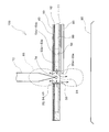
- FIG. 4 is an enlarged view of the antioxidant gas channel shown in FIG. 3. It is explanatory drawing which shows the blowing state of antioxidant gas of the antioxidant gas blowing unit in embodiment of this invention. It is explanatory drawing which shows the antioxidant gas flow path of the antioxidant gas blowing unit in other embodiment of this invention. It is a perspective view which shows the structure of the antioxidant gas blowing unit in other embodiment of this invention. It is explanatory drawing which shows the blowing state of antioxidant gas of the antioxidant gas blowing unit in other embodiment of this invention.
- the antioxidant gas blowing unit 100 of the present embodiment includes a hollow plate-shaped base portion 10 having antioxidant gas flow paths 53 and 54 formed therein, and antioxidant gas flow paths 53 and 54.
- the antioxidant gas flow channel 53 includes a plurality of outlets 35 for blowing out the antioxidant gas toward the center of the through hole 30.
- the antioxidant gas flow paths 53 and 54 include a labyrinth 50 that changes the flow direction at least twice between the antioxidant gas inlet 20 and each outlet 35.
- the labyrinth 50 includes a plurality of inner peripheral blocks 51 and a plurality of outer peripheral blocks 52 arranged at the periphery of the through hole 30, and the circumferential gaps between the blocks 51 and 52 are respectively provided with an antioxidant gas flow.
- Paths 53 and 54 are configured.
- a film heater 40 for heating the antioxidant gas flowing through the antioxidant gas flow paths 53 and 54 is attached to the outer surface of the region where the labyrinth 50 of the base 10 is disposed.
- a torch electrode 80 is attached to the lower side of the base 10 to generate a spark with the wire tail 73 extending from the tip of the capillary 72 to form the wire tail 73 into a free air ball.
- the antioxidant gas blowing unit 100 is attached to a bonding head (not shown) to which the bonding arm 71 is attached, and moves in the XY direction together with the bonding arm 71 and the capillary 72.
- the antioxidant gas may be an inert gas such as nitrogen or argon.
- a gas mixed with a reducing gas such as hydrogen may be used.
- the base unit 10 includes a main body 11 having a recess 60 therein, and a lid 12 that is attached on the main body 11 and forms a hollow portion through which an antioxidant gas flows between the recess 60 in the main body 11. Yes.
- a film heater 40 is attached on the lid 12 of the base 10 and a cover plate 13 is attached thereon.
- the lid 12 is provided with an antioxidant gas inlet 20 through which antioxidant gas flows into the recess 60 of the main body 11, and the cover plate 13 communicates with the antioxidant gas inlet 20 at a position corresponding to the antioxidant gas inlet 20 of the lid 12.
- a gas hole 21 is provided.
- An antioxidant gas introduction pipe 22 for introducing an antioxidant gas is attached to the gas hole 21 of the cover plate 13.
- the body 11, the lid 12, the film heater 40, and the cover plate 13 are provided with holes 31, 32, 41, and 34, respectively, through which the capillaries 72 pass.
- the main body 11, the lid 12, and the cover plate 13 are each made of ceramic, and as shown in FIG. 2, the main body 11, the lid 12, the film heater 40, and the cover plate 13 are stacked and sintered in this order. Or assembled with adhesive.
- the recess 60 provided inside the main body 11 has a narrow inlet region 61 communicating with the antioxidant gas inlet 20 of the lid 12 and a wide width on the side of the antioxidant gas inlet 20 of the protrusion 58 extending in the width direction from both sides.
- Three regions of the intermediate portion 62 and a labyrinth region 63 closer to the hole 31 than the protrusion 58 are provided.
- the labyrinth region 63 of the recess 60 is provided with a hole 31 through which the capillary 72 is inserted and removed, and is provided on the outer peripheral side of the plurality of inner peripheral blocks 51 rising from the bottom surface of the recess 60 and the inner peripheral block 51.
- a plurality of outer peripheral blocks 52 rising from the bottom surface of 60 and the projections 58 are arranged in series, and are arranged in parallel with the first entrance side block 57 of the rectangular parallelepiped rising from the bottom surface of the recess 60 and the first entrance side block 57.
- a rectangular parallelepiped second entrance side block 56 that is longer than the first entrance side block 57 is provided.
- the inner peripheral block 51 arranged at the periphery of the hole 31 includes five blocks, a first inner peripheral block 51a to a fifth inner peripheral block 51e.
- the outer peripheral side block 52 includes five blocks from the first outer peripheral side block 52a to the fifth outer peripheral side block 52e.
- each of the first to fifth inner peripheral blocks 51a to 51e has a shape in which a small protrusion protruding in the outer peripheral direction is provided on the hypotenuse part of the substantially trapezoidal shape. More specifically, the first to fifth inner peripheral blocks 51a to 51e include inner surfaces 511a to 511e that are partial cylindrical surfaces along the outer periphery of the hole 31, and left and right sides extending from the inner surfaces 511a to 511e toward the outer peripheral side. Side surfaces 512a to 512e, planar outer surfaces 514a to 514e facing the inner surfaces 511a to 511e, and corners 513a to 513e projecting outward from the outer surfaces 514a to 514e.
- the side surfaces 512a to 512e of the first to fifth inner peripheral blocks 51a to 51e are parallel to each other, and the antioxidant gas flow passage 53a from the outer peripheral side of the first to fifth inner peripheral blocks 51a to 51e toward the hole 31. To 53e are formed.
- the end surfaces of the antioxidant gas flow paths 53a to 53e on the hole 31 side form first to fifth blowing ports 35a to 35e, respectively, and the inner surfaces 511a of the first to fifth inner peripheral blocks 51a to 51e.
- ⁇ 511e and each of the holes 31 and 32 provided in the main body 11 and the lid 12 form a through hole 30 penetrating the base body portion 10.
- Arc-shaped first to fifth outer peripheral blocks 52a to 52e are provided on the outer peripheral side of the first to fifth inner peripheral blocks 51a to 51e.
- the first to fifth outer peripheral blocks 52a to 52e have such curvatures that the left end portions 524a to 524e and the right end portions 523a to 523e face the outer surfaces 514a to 514e of the first to fifth inner peripheral blocks 51a to 51e, respectively.
- the gaps between the first to fifth outer peripheral blocks 52a to 52e form antioxidant gas flow paths 54a to 54e.
- the circumferential positions of the antioxidant gas flow paths 54a to 54e are the circumferential directions of the antioxidant gas flow paths 53a to 53e, which are gaps between the first inner circumferential side block 51a and the fifth inner circumferential side block 51e. The position is shifted.
- each of the antioxidant gas channels 53a to 53e and each of the antioxidant gas channels 54a to 54e are alternately arranged at equal central angles in the circumferential direction.
- the antioxidant gas that has entered the labyrinth region 63 hits the second inlet side block 56 and flows along the second inlet side block 56 by changing the flow direction in the width direction of the main body 11 by the second inlet side block 56.
- a labyrinth 50 comprising first to fifth inner peripheral blocks 51a to 51e and first to fifth outer peripheral blocks 52a to 52e. It flows toward you.
- the antioxidant gas moves toward the hole 31 through the antioxidant gas flow paths 54a to 54e, which are gaps between the first outer peripheral block 52a and the fifth outer peripheral block 52e.
- the second flow direction is changed), and blows out from the first to fifth outlets 35a to 35e toward the center of the hole 31 through the antioxidant gas passages 53a to 53e.
- the film heater 40 is attached to a region corresponding to the labyrinth region 63 of the recess 60 of the main body 11 of the lid 12, the antioxidant gas that has entered the labyrinth region 63 is removed from the film heater 40. It will be heated by.
- the labyrinth region 63 is provided with a labyrinth 50 including first to fifth inner peripheral blocks 51a to 51e and first to fifth outer peripheral blocks 52a to 52e, and a surface for heating the antioxidant gas. Therefore, the antioxidant gas is effectively heated by the labyrinth 50 to reach an appropriate temperature and is blown out from the first to fifth outlets 35a to 35e toward the center of the hole 31.
- the antioxidant gas blown out from the first to fifth blowing ports 35a to 35e flows out through the hole 31 of the main body 11 to the lower side (substrate 90 side) of the antioxidant gas blowing unit 100. At the same time, it flows out through the holes 32, 41, 34 of the lid 12, the film heater 40, and the cover plate 13 to the upper side of the antioxidant gas blowing unit 100. And the antioxidant gas area
- the labyrinth 50 has an antioxidant gas inlet for the antioxidant gas that has flowed into the labyrinth region 63 of the recess 60 by changing the direction of the flow of the antioxidant gas at least twice.
- the velocity component in the direction from 20 to the hole 31 is reduced, the direction of the flow is aligned with the direction from the first to fifth blowing ports 35a to 35e toward the center of the hole 31, and the first to fifth blowing ports 35a to 35a- Since the flow rate of the antioxidant gas blown out from 35e can be made uniform, the antioxidant gas region 65 extending upward and downward of the antioxidant gas blowing unit 100 shown in FIG. 5 is substantially vertical along the axial direction of the capillary 72. Direction.
- the antioxidant gas blowing unit 100 of this embodiment has a thin plate-like structure, and the antioxidant gas can be evenly blown from the first to fifth blowing ports 35a to 35e. Since the antioxidant gas region 65 can be satisfactorily formed even with a small flow rate and a sufficient heat exchange area is ensured by the labyrinth 50, the temperature of the antioxidant gas is set to 100 ° C. by the small-capacity film heater 40. Can be raised to a degree. Thereby, the free air ball 74 can be appropriately heated to ensure the bonding quality. In addition, since the structure can be made compact, it can be easily incorporated into a wire bonding apparatus, and can be made lightweight so that it can be moved in the XY directions at a high speed and the bonding speed can be improved. Play.
- the torch electrode 80 is disposed below the thin plate-like antioxidant gas blowing unit 100, the flow of the antioxidant gas is not biased by the torch electrode 80. Can be evenly blown out from the first to fifth blowing ports 35a to 35e, and the antioxidant gas region 65 can be formed satisfactorily.
- the first to fifth inner peripheral blocks 51a to 51e have been described as having a shape in which small corners 513a to 513e protruding in the outer peripheral direction are provided on the oblique side portion of the substantially trapezoidal shape.
- the corner portions 513a to 513e may not be provided, and may be substantially trapezoidal as shown in FIG.
- the first to fifth outer peripheral blocks 52a to 52e have the left end portions 524a to 524e and the right end portions 523a to 523e, respectively, to the first to fifth inner peripheral blocks 51a to 51e.
- the curvature is directed toward the outer surfaces 514a to 514e, the large curvature does not have to be as described above, and simple partial rings as shown in FIG. 6 are arranged at equal intervals. It is good also as such a structure.
- the labyrinth 50 has been described as a two-stage configuration of the inner peripheral side block 51 and the outer peripheral side block 52, a block having three or more stages around the hole 31 may be arranged.
- the film heater 40 may not be in the form of a film as long as it is a thin heater, and a plurality of thin heaters may be dispersed and disposed on the lid 12. This embodiment has the same effect as the embodiment described above with reference to FIGS.
- the torch electrode 80 is arranged inside the antioxidant gas blowing unit 100. As shown in FIGS. 7 and 8, in this embodiment, the torch electrode 80 is inserted in parallel with the surface of the main body from the end surface of the main body 11, passes through the inlet region 61 of the recess 60, and enters the first and second inlets. After passing through one of the side blocks 57 and 56 and the outer peripheral side block 52, it is disposed so as to reach the upper surface of the hole 31 through the antioxidant gas flow path 53 between the inner peripheral side blocks 51. Further, as shown in FIG.
- the torch electrode 80 is disposed below the center in the vertical direction inside the recess 60 of the main body 11, and the free air ball 74 at the tip of the capillary 72 has a thickness of the main body 11.
- the position is slightly lower than the free air ball 74 and shifted to the periphery of the through hole 30 from the free air ball 74.
- the torch electrode 80 is attached to the main body 11 so that it can be inserted and removed from the outside and its tip position can be adjusted.
- the torch electrode 80 is disposed in the antioxidant gas region 65. Surface oxidation is suppressed, and an effect is achieved that stable discharge can be performed over a long period of time.
Landscapes
- Engineering & Computer Science (AREA)
- Mechanical Engineering (AREA)
- Physics & Mathematics (AREA)
- Optics & Photonics (AREA)
- Plasma & Fusion (AREA)
- Wire Bonding (AREA)
- Resistance Heating (AREA)
Abstract
Description
Claims (8)
- 内部に酸化防止ガス流路が形成された中空板状の基体部と、
キャピラリが抜き差しされるように前記基体部の厚さ方向に貫通し、前記酸化防止ガス流路に連通して酸化防止ガスが流出する貫通穴と、
前記貫通穴の周りの前記基体部の外面に取り付けられるフィルムヒータと、
を備える酸化防止ガス吹き出しユニット。 - 請求項1に記載の酸化防止ガス吹き出しユニットであって、
前記酸化防止ガス流路は、前記貫通穴の中心に向かって酸化防止ガスを吹き出す複数の吹き出し口を備えている酸化防止ガス吹き出しユニット。 - 請求項2に記載の酸化防止ガス吹き出しユニットであって、
酸化防止ガス流路に酸化防止ガスを流入させる酸化防止ガス入り口を備え、
前記酸化防止ガス流路は、前記酸化防止ガス入り口から各吹き出し口までの間に、流れの方向を少なくとも2回変更するラビリンスを備えている酸化防止ガス吹き出しユニット。 - 請求項3に記載の酸化防止ガス吹き出しユニットであって、
前記ラビリンスは、
前記貫通穴の周縁に配置され、その間の周方向の各隙間が前記各吹き出し口を形成する複数の内周側ブロックと、
前記各内周側ブロックの外周側で、その間の周方向の各隙間が前記内周側ブロックの各隙間と周方向にずらして配置される複数の外周側ブロックと、を備える酸化防止ガス吹き出しユニット。 - 請求項3に記載の酸化防止ガス吹き出しユニットであって、
前記フィルムヒータは、前記ラビリンスの配置されている領域の前記基体部の外面に取り付けられている酸化防止ガス吹き出しユニット。 - 請求項4に記載の酸化防止ガス吹き出しユニットであって、
前記フィルムヒータは、前記ラビリンスの配置されている領域の前記基体部の外面に取り付けられている酸化防止ガス吹き出しユニット。 - 請求項3または6のいずれか1項に記載の酸化防止ガス吹き出しユニットであって、
前記キャピラリの先端から延出したワイヤテールとの間でスパークを発生させ、前記ワイヤテールをフリーエアボールに形成するトーチ電極が、基体部の外側に配置されている酸化防止ガス吹き出しユニット。 - 請求項3または6のいずれか1項に記載の酸化防止ガス吹き出しユニットであって、
前記キャピラリの先端から延出したワイヤテールとの間でスパークを発生させ、前記ワイヤテールをフリーエアボールに形成するトーチ電極が、基体部の内側に配置されている酸化防止ガス吹き出しユニット。
Priority Applications (5)
| Application Number | Priority Date | Filing Date | Title |
|---|---|---|---|
| CN201280055529.2A CN103930980B (zh) | 2012-01-26 | 2012-11-30 | 防止氧化的气体的吹送单元 |
| SG11201403542XA SG11201403542XA (en) | 2012-01-26 | 2012-11-30 | Antioxidant gas supply unit |
| KR1020147014751A KR101612012B1 (ko) | 2012-01-26 | 2012-11-30 | 산화 방지 가스 취출 유닛 |
| JP2013555144A JP5592029B2 (ja) | 2012-01-26 | 2012-11-30 | 酸化防止ガス吹き出しユニット |
| US14/321,134 US9044821B2 (en) | 2012-01-26 | 2014-07-01 | Antioxidant gas supply unit |
Applications Claiming Priority (2)
| Application Number | Priority Date | Filing Date | Title |
|---|---|---|---|
| JP2012014236 | 2012-01-26 | ||
| JP2012-014236 | 2012-01-26 |
Related Child Applications (1)
| Application Number | Title | Priority Date | Filing Date |
|---|---|---|---|
| US14/321,134 Continuation US9044821B2 (en) | 2012-01-26 | 2014-07-01 | Antioxidant gas supply unit |
Publications (1)
| Publication Number | Publication Date |
|---|---|
| WO2013111452A1 true WO2013111452A1 (ja) | 2013-08-01 |
Family
ID=48873193
Family Applications (1)
| Application Number | Title | Priority Date | Filing Date |
|---|---|---|---|
| PCT/JP2012/081135 Ceased WO2013111452A1 (ja) | 2012-01-26 | 2012-11-30 | 酸化防止ガス吹き出しユニット |
Country Status (7)
| Country | Link |
|---|---|
| US (1) | US9044821B2 (ja) |
| JP (1) | JP5592029B2 (ja) |
| KR (1) | KR101612012B1 (ja) |
| CN (1) | CN103930980B (ja) |
| SG (1) | SG11201403542XA (ja) |
| TW (1) | TWI500093B (ja) |
| WO (1) | WO2013111452A1 (ja) |
Families Citing this family (3)
| Publication number | Priority date | Publication date | Assignee | Title |
|---|---|---|---|---|
| JP2014075519A (ja) * | 2012-10-05 | 2014-04-24 | Shinkawa Ltd | 酸化防止ガス吹き出しユニット |
| JP5916814B2 (ja) * | 2014-08-06 | 2016-05-11 | 株式会社カイジョー | ボンディング方法及びボンディング装置 |
| JP6467281B2 (ja) | 2015-04-30 | 2019-02-13 | 日鉄マイクロメタル株式会社 | ボンディングワイヤのボール形成方法 |
Citations (3)
| Publication number | Priority date | Publication date | Assignee | Title |
|---|---|---|---|---|
| JPS5972730U (ja) * | 1982-11-05 | 1984-05-17 | 株式会社東芝 | ワイヤボンデイング装置 |
| JPS63147338A (ja) * | 1986-12-11 | 1988-06-20 | Toshiba Corp | ワイヤボンデイング装置用ト−チ |
| JP2008130825A (ja) * | 2006-11-21 | 2008-06-05 | Kaijo Corp | ワイヤボンディング装置 |
Family Cites Families (23)
| Publication number | Priority date | Publication date | Assignee | Title |
|---|---|---|---|---|
| JPS5972730A (ja) | 1982-10-20 | 1984-04-24 | Sumitomo Electric Ind Ltd | 半導体単結晶の加工方法 |
| JPS60244034A (ja) * | 1984-05-18 | 1985-12-03 | Mitsubishi Electric Corp | ワイヤボンデイング用雰囲気形成装置 |
| US4976393A (en) | 1986-12-26 | 1990-12-11 | Hitachi, Ltd. | Semiconductor device and production process thereof, as well as wire bonding device used therefor |
| JPS63164230A (ja) * | 1986-12-26 | 1988-07-07 | Hitachi Ltd | ワイヤボンディング方法 |
| JPS63266845A (ja) | 1987-04-24 | 1988-11-02 | Hitachi Ltd | ワイヤボンデイング装置 |
| JPS6454742A (en) * | 1987-08-26 | 1989-03-02 | Hitachi Ltd | Bonding method and device |
| JPH03253045A (ja) * | 1990-03-02 | 1991-11-12 | Hitachi Ltd | ワイヤボンディング装置 |
| JP3128718B2 (ja) * | 1993-09-21 | 2001-01-29 | 株式会社新川 | ワイヤボンデイング方法 |
| US6180891B1 (en) * | 1997-02-26 | 2001-01-30 | International Business Machines Corporation | Control of size and heat affected zone for fine pitch wire bonding |
| JP2003037131A (ja) * | 2001-07-25 | 2003-02-07 | Sanyo Electric Co Ltd | ボンディング装置 |
| JP4043495B2 (ja) * | 2006-04-20 | 2008-02-06 | 株式会社カイジョー | ワーククランプ及びワイヤボンディング装置 |
| US20070251980A1 (en) | 2006-04-26 | 2007-11-01 | Gillotti Gary S | Reduced oxidation system for wire bonding |
| US7614538B2 (en) * | 2006-05-15 | 2009-11-10 | Kulicke And Soffa Industries, Inc. | Device clamp for reducing oxidation in wire bonding |
| JP2008034811A (ja) * | 2006-07-03 | 2008-02-14 | Shinkawa Ltd | ワイヤボンディング装置におけるボール形成装置及びボンディング装置 |
| US7628307B2 (en) * | 2006-10-30 | 2009-12-08 | Asm Technology Singapore Pte Ltd. | Apparatus for delivering shielding gas during wire bonding |
| JP4700633B2 (ja) * | 2007-02-15 | 2011-06-15 | 株式会社新川 | ワイヤ洗浄ガイド |
| JP2009105114A (ja) * | 2007-10-22 | 2009-05-14 | Shinkawa Ltd | ワイヤボンディング装置及びボール形成方法 |
| CN101971314B (zh) * | 2008-06-10 | 2013-10-09 | 库力索法工业公司 | 用于在引线接合操作中降低氧化的输气系统 |
| US20100078464A1 (en) * | 2008-10-01 | 2010-04-01 | Kabushiki Kaisha Shinkawa | Wire bonding apparatus and ball forming method |
| TWM374146U (en) * | 2009-09-30 | 2010-02-11 | Sureway Technology Co Ltd | Air feeder applied to welding line device |
| TWI429009B (zh) * | 2010-05-12 | 2014-03-01 | 南茂科技股份有限公司 | 導氣管裝置 |
| US8186562B1 (en) * | 2010-12-14 | 2012-05-29 | Asm Technology Singapore Pte Ltd | Apparatus for increasing coverage of shielding gas during wire bonding |
| JP5296233B2 (ja) * | 2012-02-07 | 2013-09-25 | 株式会社新川 | ワイヤボンディング装置 |
-
2012
- 2012-11-30 CN CN201280055529.2A patent/CN103930980B/zh not_active Expired - Fee Related
- 2012-11-30 WO PCT/JP2012/081135 patent/WO2013111452A1/ja not_active Ceased
- 2012-11-30 KR KR1020147014751A patent/KR101612012B1/ko not_active Expired - Fee Related
- 2012-11-30 SG SG11201403542XA patent/SG11201403542XA/en unknown
- 2012-11-30 JP JP2013555144A patent/JP5592029B2/ja not_active Expired - Fee Related
- 2012-12-20 TW TW101148619A patent/TWI500093B/zh not_active IP Right Cessation
-
2014
- 2014-07-01 US US14/321,134 patent/US9044821B2/en not_active Expired - Fee Related
Patent Citations (3)
| Publication number | Priority date | Publication date | Assignee | Title |
|---|---|---|---|---|
| JPS5972730U (ja) * | 1982-11-05 | 1984-05-17 | 株式会社東芝 | ワイヤボンデイング装置 |
| JPS63147338A (ja) * | 1986-12-11 | 1988-06-20 | Toshiba Corp | ワイヤボンデイング装置用ト−チ |
| JP2008130825A (ja) * | 2006-11-21 | 2008-06-05 | Kaijo Corp | ワイヤボンディング装置 |
Also Published As
| Publication number | Publication date |
|---|---|
| JP5592029B2 (ja) | 2014-09-17 |
| TW201344815A (zh) | 2013-11-01 |
| TWI500093B (zh) | 2015-09-11 |
| CN103930980B (zh) | 2016-11-23 |
| KR101612012B1 (ko) | 2016-04-12 |
| US20140311590A1 (en) | 2014-10-23 |
| CN103930980A (zh) | 2014-07-16 |
| JPWO2013111452A1 (ja) | 2015-05-11 |
| US9044821B2 (en) | 2015-06-02 |
| KR20140098106A (ko) | 2014-08-07 |
| SG11201403542XA (en) | 2014-10-30 |
Similar Documents
| Publication | Publication Date | Title |
|---|---|---|
| JP5793473B2 (ja) | ボンディング装置用ヒータ及びその冷却方法 | |
| JP5592029B2 (ja) | 酸化防止ガス吹き出しユニット | |
| JP5618974B2 (ja) | ワイヤボンディング装置 | |
| JP7283872B2 (ja) | 保持装置 | |
| JP6650808B2 (ja) | 保持装置 | |
| JP2014075519A (ja) | 酸化防止ガス吹き出しユニット | |
| JP6047724B2 (ja) | ボンディング装置用ヒータ、ボンディング装置用ヒータ組立体及びボンディング装置 | |
| US10192847B2 (en) | Rapid cooling system for a bond head heater | |
| JP6632856B2 (ja) | ボンディングヘッドおよび実装装置 | |
| JP6149241B2 (ja) | ボンディング装置用ヒータ及びその冷却方法 | |
| US9415456B2 (en) | Antioxidant gas blow-off unit | |
| US20260040883A1 (en) | Retention device | |
| JP5254427B2 (ja) | ワイヤボンディング装置 | |
| JPH0485840A (ja) | 微細金属球の配列装置及びその配列装置を用いた微細金属球の配列方法 | |
| JP2015109485A (ja) | ボンディング装置用ヒータ及びその冷却方法 | |
| JP2011035055A (ja) | ワーククランプ及びワイヤボンディング装置 |
Legal Events
| Date | Code | Title | Description |
|---|---|---|---|
| 121 | Ep: the epo has been informed by wipo that ep was designated in this application |
Ref document number: 12866484 Country of ref document: EP Kind code of ref document: A1 |
|
| ENP | Entry into the national phase |
Ref document number: 2013555144 Country of ref document: JP Kind code of ref document: A |
|
| ENP | Entry into the national phase |
Ref document number: 20147014751 Country of ref document: KR Kind code of ref document: A |
|
| NENP | Non-entry into the national phase |
Ref country code: DE |
|
| 122 | Ep: pct application non-entry in european phase |
Ref document number: 12866484 Country of ref document: EP Kind code of ref document: A1 |