WO2013088593A1 - 空気調和機の室外機 - Google Patents
空気調和機の室外機 Download PDFInfo
- Publication number
- WO2013088593A1 WO2013088593A1 PCT/JP2012/004269 JP2012004269W WO2013088593A1 WO 2013088593 A1 WO2013088593 A1 WO 2013088593A1 JP 2012004269 W JP2012004269 W JP 2012004269W WO 2013088593 A1 WO2013088593 A1 WO 2013088593A1
- Authority
- WO
- WIPO (PCT)
- Prior art keywords
- outdoor unit
- long side
- handle
- top panel
- air conditioner
- Prior art date
Links
Images


Classifications
-
- F—MECHANICAL ENGINEERING; LIGHTING; HEATING; WEAPONS; BLASTING
- F24—HEATING; RANGES; VENTILATING
- F24F—AIR-CONDITIONING; AIR-HUMIDIFICATION; VENTILATION; USE OF AIR CURRENTS FOR SCREENING
- F24F1/00—Room units for air-conditioning, e.g. separate or self-contained units or units receiving primary air from a central station
- F24F1/06—Separate outdoor units, e.g. outdoor unit to be linked to a separate room comprising a compressor and a heat exchanger
- F24F1/56—Casing or covers of separate outdoor units, e.g. fan guards
Definitions
- the present invention relates to an outdoor unit of an air conditioner, and particularly to a handle structure of the outdoor unit.
- the outdoor unit of the air conditioner has a handle so that people can carry it when installing it.
- a handle is provided on the top panel side surface so as to protrude outward from the side surface of the outer body of the outdoor unit (see Patent Document 1).
- a box is composed of a box body and an upper surface member that closes an opening on the upper surface of the box body, and the upper surface member is integrally formed at the end portion on the short side.
- the side surface portion of the box body has a concave portion that is integrally recessed inside the box body at a position corresponding to the grip portion, and a flat portion that is adjacent to the concave portion.
- the upper end surface is recessed inside the box so as to be integrated with the upper end surface of the flat portion adjacent to the recess, and the upper end surface of the recess is located in contact with or close to the lower surface of the upper surface member.
- the outdoor unit of an air conditioner having a handle that protrudes outward from the side surface of the box body on the side of the top panel is increased in size by the amount of protrusion, and only for this handle Moreover, a packing member will become large. Moreover, since the magnitude
- a heat exchanger provided inside the outdoor unit is often formed in an L shape in order to reduce the size of the outdoor unit of the product. For this reason, a structure in which a lattice-like crosspiece is left open so as not to hinder ventilation of the heat exchanger on the side surface side of the panel covering the outside of the heat exchanger is generally used.
- Patent Document 2 when a space is provided to provide a recess and a hand can be inserted from the side, it is difficult to manufacture an opening that allows air to flow into the recess, and the recess is formed in the heat exchanger. Since the flow path of the inflowing air is shielded, there is a problem that the efficiency of the heat exchanger is reduced.
- An object of the present invention is to provide an outdoor unit of an air conditioner that does not shield the air flowing into the heat exchanger without increasing the size of the outdoor unit and the packaging by providing a handle in the outdoor unit of the air conditioner having a handle. Is to provide a machine.
- An outdoor unit of an air conditioner according to the present invention is an outdoor unit of an air conditioner in which a handle is provided on a substantially rectangular top panel that covers an upper opening of an outer unit main body outline including a machine room and a fan room.
- the long side handle protrudes outward from the long side portion of the top panel, but in the top view, outward from the tip position of the leg portion provided on the bottom surface of the exterior unit outer shell. Because it is provided so that it does not protrude, it does not increase the size of the outdoor unit and packing size due to the presence of the handle on the long side, and it does not block the opening where air flows into the heat exchanger An outdoor unit of an air conditioner that does not reduce the efficiency of the heat exchanger can be obtained.
- FIG. 5 is a YY cross-sectional view of FIG. 4. It is a perspective view which shows the external component of the outdoor unit 100 of the air conditioner which concerns on Embodiment 2 of this invention. It is a top view of the outdoor unit 100 of FIG.
- FIG. 1 is a front view of an outdoor unit 100 for an air-conditioning apparatus according to Embodiment 1 of the present invention.
- an outdoor unit 100 for an air conditioner according to Embodiment 1 includes an outdoor unit main body outline 20 formed in a box shape, and the outdoor unit main body outline 20 includes a leg portion 21. 22, an outer panel 23, a side panel 24, and a top panel 25. Further, the front panel portion 26 of the outer panel 23 is provided with an air outlet 27 for blowing out air from the blower.
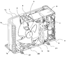
- FIG. 2 is a perspective view showing the inside of the outdoor unit 100 shown in FIG.
- the outdoor unit 100 includes a blower chamber 5 and a machine chamber 9 inside an outdoor unit main body shell 20, and each chamber is divided by a separator 10.
- Each component inside the outdoor unit 100 is held on a bottom base 22 having legs 21. Since the leg portion 21 is used to fix the outdoor unit 100 when the outdoor unit 100 is installed, the leg portion 21 is arranged to protrude outward from the outer unit main body outer shell 20 so that a bolt or the like can be set.
- the machine room 9 is provided with a compressor 6, a refrigerant pipe 7, and an electrical component box 8.
- the refrigerant sent from the indoor unit is compressed by the compressor 6, passes through the refrigerant pipe 7, and is sent to the heat exchanger 1.
- the electrical component box 8 supplies power to each component.
- the blower chamber 5 is provided with a heat exchanger 1 bent into an L shape, a blower 2 (for example, a propeller fan), a motor 3 that drives the blower 2, and a motor support 4 that holds the motor 3. ing.
- the heat exchanger 1 includes a side surface side plane portion 1a, a corner portion 1b, and a back surface side plane portion 1c.
- air blower 2 operates, air flows into the outdoor unit 100 through the side surface side plane portion 1a, the corner portion 1b, and the back surface side plane portion 1c of the heat exchanger 1, and the air flows into the air blower 2 Is further blown out from the blowout port 27 of the front panel unit 26 in front of the outdoor unit 100.
- the refrigerant in the heat exchanger 1 is cooled by air, and the air that has passed through the heat exchanger 1 is overheated by exchanging heat with the refrigerant.
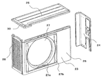
- FIG. 3 is a perspective view showing outer parts of the outdoor unit 100 of FIG.
- the outdoor unit 100 includes the outdoor unit main body shell 20 including the base 22, the outer panel 23, the side panel 24, and the top panel 25.
- the outer panel 23 is formed to cover the front surface, the left side surface, and the corners between the left side surface and the back surface of the outdoor unit 100 in a front view.
- the side panel 24 is formed so as to cover the right side surface of the outdoor unit 100 and the right side end portion of the back surface in a front view.
- the top panel 25 is configured as a lid member that covers the upper opening of the outdoor unit main body outline 20.
- the configuration of the outer parts is not limited to the above, and for example, the outer panel 23 and the side panel 24 may be integrated.
- a large number of openings 28 are formed in the left side surface portion of the outer panel 23 so as to allow air to flow into the side surface side plane portion 1a of the heat exchanger 1. Further, a bell mouth 27a that forms the air outlet 27 and an opening 27b for attaching a protective guard are provided in a portion of the outer panel 23 corresponding to the blower chamber 5 of the front panel portion 26.
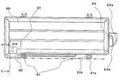
- FIG. 4 is a top view of the outdoor unit 100 of FIG.
- FIG. 5 is a YY cross-sectional view of FIG.
- the top panel 25 has a substantially rectangular shape and is a lid member that covers the upper surface of the outdoor unit 100.
- the long side handle 30 is provided in the edge part of this long side part (long side part by the side of the fan room 5) of this top panel 25 so that it may protrude outside (front side) from a long side part. . Further, the long side handle 30 is provided so as not to protrude outward from the distal end position 21a of the leg portion 21 in a top view.
- the long side handle 30 protrudes outward from the long side portion of the top panel 25, but is outward from the virtual line 21 b parallel to the front panel portion 26 at the distal end position 21 a of the leg portion 21 when viewed from above. It is provided so as not to protrude.
- the long side handle 30 is provided in the front side long side part of the top panel 25 in FIG. 4, you may provide in the back side long side part by the positional relationship similar to the above.
- the long side handle 30 is preferably formed integrally with the top panel 25 by sheet metal processing or the like.
- a display 31 that clearly indicates the position of the handle 30 is provided in the vicinity of the long side handle 30.
- the display 31 is, for example, by engraving or ink printing, and may be any technique that does not easily disappear. Providing the display 31 makes it easier for the carrier to find the location of the long side handle 30.
- the long side handle 30 has a concave portion 32 having a size capable of inserting a carrier's finger on the back side.
- the lower end 30a of the long side handle 30 is bent into a U shape.
- the long side handle 30 is preferably arranged at the end of the long side of the top panel 25 on the blower chamber 5 side. Therefore, the short side handle 34 is disposed on the right side surface portion on the machine room 9 side. Further, as shown in FIGS. 4 and 1, the right side panel 24 is provided with a protruding portion 24 a in which a valve or the like is accommodated, and the protruding portion 24 a is generally larger than the short side handle 34. It has become. Therefore, the short side handle 34 may be a handle having the same configuration as the conventional one. In addition, as shown in FIG.
- the short side handle 34 may be disposed near the upper end of the side panel 24, and when the same configuration as the long side handle 30 is adopted, the short side handle 34 is You may arrange
- the long side handle 30 and the short side handle 34 are arranged at substantially diagonal positions. That is, when the outdoor unit 100 is lifted by these handles 30 and 34, if the outdoor unit 100 is disposed at a substantially diagonal position so that the center of gravity of the outdoor unit 100 is positioned at the approximate center of the line connecting both hands, Balanced and easy to carry.
- the long side handle 30 protrudes outward from the long side portion of the top panel 25, but on the bottom surface portion of the outdoor unit main body outline 20 in a top view. Since it is provided so as not to protrude outward from the tip position 21 a of the provided leg portion 21, the packaging size does not increase only for the long side handle 30.
- an opening 28 is provided in the left side surface portion of the outer panel 23 in order to allow air to flow into the heat exchanger 1.
- air flows through the path as described above to perform heat exchange.
- the long side handle 30 since the long side handle 30 is disposed in a place unrelated to the air flow, the long side handle 30 causes the heat exchanger to exchange heat. The efficiency of 1 is not reduced.
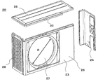
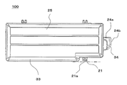
- FIG. FIG. 6 is a perspective view showing outer parts of the outdoor unit 100 of the air conditioner according to Embodiment 2 of the present invention
- FIG. 7 is a top view of the outdoor unit 100 of FIG.
- the same reference numerals are used for the same or corresponding components as those of the first embodiment unless otherwise specified.
- an outdoor unit main body shell 20 including only the outer panel 23, the side panel 24, and the top panel 25 is shown in FIG.
- the base 22 having the leg portions 21 is not shown.
- the long side handle 33 provided on the long side portion of the top panel 25 the protruding amount is the same as that of the first embodiment, but the length in the longitudinal direction is the same as the inner diameter D of the outlet 27. The length is equivalent or longer. That is, as shown in FIG. 7, the long side handle 33 is provided on the front side of the top panel 25, and protrudes outward from the long side portion of the top panel 25.
- the length of the side handle 33 in the longitudinal direction is equal to or longer than the inner diameter D of the air outlet 27.
- a recess as shown in FIG. 5 and a lower end bent into a U shape are provided on the back side of the long side handle 33.
- the snow accumulated on the upper part melts and flows along the front panel portion 26 if not operated for a while, and enters the outlet 27. May flow in. Then, when the outside air temperature such as at night falls while the air is flowing in, this water flow freezes and an ice column is generated in the outlet 27. Or the water collected in the lower part of the blower outlet 27 may freeze, and a reverse ice column may generate
- produce when snow accumulates in the upper part of the outdoor unit 100 in winter and the outside air temperature changes near 0 ° C., the snow accumulated on the upper part melts and flows along the front panel portion 26 if not operated for a while, and enters the outlet 27. May flow in. Then, when the outside air temperature such as at night falls while the air is flowing in, this water flow freezes and an ice column is generated in the outlet 27. Or the water collected in the lower part of the blower outlet 27 may freeze, and a reverse ice column may generate
- the long side handle 33 in the longitudinal direction since the length of the long side handle 33 in the longitudinal direction is equal to or longer than the inner diameter of the outlet 27, the long side handle 33 serves as a bag, and the upper part of the outdoor unit 100 Thus, it is possible to prevent water from entering the outlet 27 and prevent the ice outlet 27 from generating ice pillars. Further, by not generating the icicle, it is possible to avoid the interference sound with the blower 2 at the start of operation or the blower breakage caused by the contact with the icicle. In addition, the longer the length of the long side handle 33 in the longitudinal direction than the inner diameter of the air outlet 27, the more it is possible to prevent the inflow from the lateral direction such as when the outside wind blows, and to obtain further effects. it can.
Landscapes
- Engineering & Computer Science (AREA)
- Chemical & Material Sciences (AREA)
- Combustion & Propulsion (AREA)
- Mechanical Engineering (AREA)
- General Engineering & Computer Science (AREA)
- Other Air-Conditioning Systems (AREA)
Abstract
Description
図1は、本発明の実施の形態1に係る空気調和機の室外機100の正面図である。
この実施の形態1に係る空気調和機の室外機100は、図1に示すように、箱形に形成された室外機本体外郭20を備え、室外機本体外郭20は、脚部21を有するベース22と、外郭パネル23と、側面パネル24と、天面パネル25と、を備えている。また、外郭パネル23の前面パネル部26には、送風機から吹き出される空気の吹出口27が設けられている。
室外機100は、室外機本体外郭20の内部に、送風機室5と機械室9とを有しており、各室はセパレーター10によって分けられている。また、室外機100内部の各部品は、脚部21を有する底面のベース22の上に保持されている。この脚部21は、室外機100を据付時、室外機100を固定するために使用されるため、ボルト等をセットできるように室外機本体外郭20よりも外方へ突出して配置されている。
前述のように、室外機100は、ベース22、外郭パネル23、側面パネル24、及び天面パネル25により構成される室外機本体外郭20を備えている。このうち、外郭パネル23は、正面視で、室外機100の前面、左側面及び左側面と背面との間の角部を覆うように形成されている。側面パネル24は、正面視で、室外機100の右側面と背面の右側端部とを覆うように形成されている。また、天面パネル25は、室外機本体外郭20の上部開口を覆う蓋部材として構成されている。なお、外郭部品の構成は、上記に限られるものではなく、例えば外郭パネル23及び側面パネル24が一体となっていてもよい。
天面パネル25は、図4に示すように、略長方形状をなしており、室外機100の上面を覆う蓋部材である。そして、この天面パネル25の長辺部(送風機室5側の長辺部)の端部に長辺側取手30が長辺部より外方(正面側)へ突出するように設けられている。さらに、この長辺側取手30は、上面視で、前記脚部21の先端位置21aより外方へ突出させないように設けられている。すなわち、長辺側取手30は、天面パネル25の長辺部より外方へ突出するが、上面視で、脚部21の先端位置21aにおける前面パネル部26と平行な仮想線21bより外方へ突出させないように設けられているのである。
また、長辺側取手30は、図4では天面パネル25の前面側長辺部に設けられているが、背面側長辺部に上記と同様の位置関係で設けてもよい。なお、長辺側取手30は、板金加工等にて天面パネル25と一体に形成することが好ましい。
図6は、本発明の実施の形態2に係る空気調和機の室外機100の外郭部品を示す斜視図であり、図7は、図6の室外機100の上面図である
なお、本実施の形態2に係る空気調和機の室外機100において、特に断らない限り、実施の形態1と同一の又は相当する構成要素については同一の符号を用いるものとする。
また、天面パネル25の長辺部に設けられた長辺側取手33に関して、その突出量は、実施の形態1と同様であるが、長手方向の長さは、吹出口27の内径Dと同等もしくはそれ以上の長さとなっている。すなわち、長辺側取手33は、図7に示すように、天面パネル25の前面側に設けた場合であり、その天面パネル25の長辺部より外方へ突出するが、その長辺側取手33の長手方向の長さは、吹出口27の内径Dと同等もしくはそれ以上の長さとなっていることを特徴としている。なお、この長辺側取手33の裏側には、図5に示したような凹部とU字状に曲げ加工された下端部が設けられている。
また、氷柱を発生させないことで、運転開始時送風機2との干渉音または氷柱と接触することによって引き起こされる送風機破損を回避することができる。
また、吹出口27の内径よりも長辺側取手33の長手方向の長さが長いほど、外風が吹いた場合など横方向からの流入を防ぐことができ、より一層の効果を得ることができる。
短辺側取手、100 室外機。
Claims (5)
- 内部に機械室と送風機室とを備える室外機本体外郭の上部開口を覆う略長方形状の天面パネルに取手を設けた空気調和機の室外機であって、
前記天面パネルの長辺部に設けられた長辺側取手と、前記天面パネルの短辺部または側面パネルに設けられた短辺側取手とを備え、
前記長辺側取手は、前記天面パネルの長辺部より外方へ突出するが、上面視で、前記室外機本体外郭の底面部に設けられた脚部の先端位置より外方へ突出させないように設けられていることを特徴とする空気調和機の室外機。 - 前記天面パネルの前面側に前記長辺側取手を設けた場合、該長辺側取手の長手方向の長さを、前面パネルの吹出口の内径と同等またはそれ以上の長さとしたことを特徴とする請求項1記載の空気調和機の室外機。
- 前記長辺側取手の位置を示す表示を前記天面パネルに設けたことを特徴とする請求項1または2記載の空気調和機の室外機。
- 前記短辺側取手を前記天面パネルの短辺部に設ける場合、該短辺側取手は、前記天面パネルの短辺部より外方へ突出するが、上面視で、前記室外機本体外郭の側面パネルに設けられた突出部の最大突出位置より外方へ突出させないように設けられていることを特徴とする請求項1~3のいずれか一項に記載の空気調和機の室外機。
- 前記長辺側取手の裏側に、手が入る凹部を有することを特徴とする請求項1~3のいずれか一項に記載の空気調和機の室外機。
Priority Applications (4)
| Application Number | Priority Date | Filing Date | Title |
|---|---|---|---|
| EP12857353.2A EP2792956B1 (en) | 2011-12-15 | 2012-07-02 | Outdoor unit of air conditioner |
| RU2014128819/12A RU2568182C1 (ru) | 2011-12-15 | 2012-07-02 | Наружный блок для устройства кондиционирования воздуха |
| AU2012354015A AU2012354015B2 (en) | 2011-12-15 | 2012-07-02 | Outdoor unit for air-conditioning apparatus |
| CN201280058617.8A CN103958974B (zh) | 2011-12-15 | 2012-07-02 | 空调的室外机 |
Applications Claiming Priority (2)
| Application Number | Priority Date | Filing Date | Title |
|---|---|---|---|
| JP2011-274467 | 2011-12-15 | ||
| JP2011274467A JP5642053B2 (ja) | 2011-12-15 | 2011-12-15 | 空気調和機の室外機 |
Publications (1)
| Publication Number | Publication Date |
|---|---|
| WO2013088593A1 true WO2013088593A1 (ja) | 2013-06-20 |
Family
ID=48612077
Family Applications (1)
| Application Number | Title | Priority Date | Filing Date |
|---|---|---|---|
| PCT/JP2012/004269 WO2013088593A1 (ja) | 2011-12-15 | 2012-07-02 | 空気調和機の室外機 |
Country Status (6)
| Country | Link |
|---|---|
| EP (1) | EP2792956B1 (ja) |
| JP (1) | JP5642053B2 (ja) |
| CN (1) | CN103958974B (ja) |
| AU (1) | AU2012354015B2 (ja) |
| RU (1) | RU2568182C1 (ja) |
| WO (1) | WO2013088593A1 (ja) |
Families Citing this family (8)
| Publication number | Priority date | Publication date | Assignee | Title |
|---|---|---|---|---|
| WO2016129077A1 (ja) * | 2015-02-12 | 2016-08-18 | 三菱電機株式会社 | 室外機 |
| MY191955A (en) * | 2016-07-25 | 2022-07-20 | Daikin Res & Development Malaysia Sdn Bhd | An air conditioner unit |
| WO2018078836A1 (ja) * | 2016-10-31 | 2018-05-03 | 三菱電機株式会社 | 空気調和装置の室外機 |
| CN210088991U (zh) * | 2018-03-14 | 2020-02-18 | 三菱电机株式会社 | 空调装置的室外单元 |
| JPWO2020053951A1 (ja) * | 2018-09-11 | 2021-05-13 | 三菱電機株式会社 | 空気調和装置の室外機 |
| CN116209859A (zh) * | 2020-10-05 | 2023-06-02 | 三菱电机株式会社 | 空调机的室外机 |
| JP7459888B2 (ja) * | 2022-02-28 | 2024-04-02 | 株式会社富士通ゼネラル | ヒートポンプサイクル装置 |
| JP7552632B2 (ja) * | 2022-02-28 | 2024-09-18 | 株式会社富士通ゼネラル | ヒートポンプサイクル装置 |
Citations (9)
| Publication number | Priority date | Publication date | Assignee | Title |
|---|---|---|---|---|
| JPH0277525U (ja) * | 1988-12-05 | 1990-06-14 | ||
| JPH06159734A (ja) * | 1992-11-30 | 1994-06-07 | Hitachi Ltd | 製品分解順序表示方式 |
| JPH07110142A (ja) * | 1993-08-20 | 1995-04-25 | Sharp Corp | 分離型空気調和機の室外ユニット |
| JPH07301434A (ja) * | 1994-05-06 | 1995-11-14 | Matsushita Seiko Co Ltd | 空調機の室外機 |
| JPH10227487A (ja) | 1997-02-18 | 1998-08-25 | Matsushita Electric Ind Co Ltd | 分離型空気調和装置の室外機 |
| JP2002081696A (ja) * | 2000-09-01 | 2002-03-22 | Mitsubishi Electric Corp | 空気調和機の室外ユニット |
| JP2007113861A (ja) | 2005-10-21 | 2007-05-10 | Hitachi Appliances Inc | 空気調和機等の室外機 |
| JP2007232276A (ja) * | 2006-03-01 | 2007-09-13 | Matsushita Electric Ind Co Ltd | 空気調和機の室外機 |
| JP2010210097A (ja) * | 2009-03-06 | 2010-09-24 | Mitsubishi Electric Corp | 空気調和機の室外機及びこれを備えた空気調和機 |
Family Cites Families (9)
| Publication number | Priority date | Publication date | Assignee | Title |
|---|---|---|---|---|
| JPS637724U (ja) * | 1986-06-30 | 1988-01-19 | ||
| RU2056012C1 (ru) * | 1994-04-29 | 1996-03-10 | Сергей Петрович Канашин | Портативный кондиционер |
| JP4555712B2 (ja) * | 2005-03-15 | 2010-10-06 | 東芝キヤリア株式会社 | 空気調和装置の室外機 |
| JP2007132590A (ja) * | 2005-11-10 | 2007-05-31 | Matsushita Electric Ind Co Ltd | 空気調和機の室外機 |
| CN100561066C (zh) * | 2005-12-13 | 2009-11-18 | 广东科龙电器股份有限公司 | 分体空调器的小型化室外机 |
| JP2010065951A (ja) * | 2008-09-11 | 2010-03-25 | Toshiba Carrier Corp | 熱源機 |
| KR20100046389A (ko) * | 2008-10-27 | 2010-05-07 | 엘지전자 주식회사 | 공기조화기의 실외기 |
| JP5565072B2 (ja) * | 2010-01-25 | 2014-08-06 | ダイキン工業株式会社 | 室外機用取っ手及びこれを備えた室外機 |
| JP5220076B2 (ja) * | 2010-09-29 | 2013-06-26 | 三菱電機株式会社 | 室外機及びこれを備えた空気調和装置 |
-
2011
- 2011-12-15 JP JP2011274467A patent/JP5642053B2/ja active Active
-
2012
- 2012-07-02 EP EP12857353.2A patent/EP2792956B1/en active Active
- 2012-07-02 AU AU2012354015A patent/AU2012354015B2/en active Active
- 2012-07-02 CN CN201280058617.8A patent/CN103958974B/zh active Active
- 2012-07-02 RU RU2014128819/12A patent/RU2568182C1/ru active
- 2012-07-02 WO PCT/JP2012/004269 patent/WO2013088593A1/ja unknown
Patent Citations (9)
| Publication number | Priority date | Publication date | Assignee | Title |
|---|---|---|---|---|
| JPH0277525U (ja) * | 1988-12-05 | 1990-06-14 | ||
| JPH06159734A (ja) * | 1992-11-30 | 1994-06-07 | Hitachi Ltd | 製品分解順序表示方式 |
| JPH07110142A (ja) * | 1993-08-20 | 1995-04-25 | Sharp Corp | 分離型空気調和機の室外ユニット |
| JPH07301434A (ja) * | 1994-05-06 | 1995-11-14 | Matsushita Seiko Co Ltd | 空調機の室外機 |
| JPH10227487A (ja) | 1997-02-18 | 1998-08-25 | Matsushita Electric Ind Co Ltd | 分離型空気調和装置の室外機 |
| JP2002081696A (ja) * | 2000-09-01 | 2002-03-22 | Mitsubishi Electric Corp | 空気調和機の室外ユニット |
| JP2007113861A (ja) | 2005-10-21 | 2007-05-10 | Hitachi Appliances Inc | 空気調和機等の室外機 |
| JP2007232276A (ja) * | 2006-03-01 | 2007-09-13 | Matsushita Electric Ind Co Ltd | 空気調和機の室外機 |
| JP2010210097A (ja) * | 2009-03-06 | 2010-09-24 | Mitsubishi Electric Corp | 空気調和機の室外機及びこれを備えた空気調和機 |
Also Published As
| Publication number | Publication date |
|---|---|
| JP5642053B2 (ja) | 2014-12-17 |
| JP2013124822A (ja) | 2013-06-24 |
| CN103958974B (zh) | 2016-12-28 |
| RU2568182C1 (ru) | 2015-11-10 |
| EP2792956A4 (en) | 2016-01-13 |
| EP2792956B1 (en) | 2018-06-27 |
| EP2792956A1 (en) | 2014-10-22 |
| CN103958974A (zh) | 2014-07-30 |
| AU2012354015A1 (en) | 2014-05-29 |
| AU2012354015B2 (en) | 2015-08-13 |
Similar Documents
| Publication | Publication Date | Title |
|---|---|---|
| JP5642053B2 (ja) | 空気調和機の室外機 | |
| JP5523822B2 (ja) | 空気調和装置の室外ユニット | |
| JP5706149B2 (ja) | 電気装置 | |
| JP5218689B2 (ja) | 冷凍装置の室外ユニット | |
| JP5870553B2 (ja) | 空気調和機の室外機 | |
| JP2011153806A (ja) | 空気調和装置の室外ユニット | |
| JP5496697B2 (ja) | 空気調和装置の室外ユニット | |
| WO2016060157A1 (ja) | 空気調和機の室外機 | |
| JP5058004B2 (ja) | 室外機及びこれを備えた空気調和機 | |
| JP5071573B2 (ja) | 空気調和機 | |
| JP5108241B2 (ja) | 風向ガイドユニット | |
| JP5511414B2 (ja) | 給湯室外機 | |
| CN207940849U (zh) | 一种吸尘器 | |
| JP2011133149A (ja) | ヒートポンプ式熱源装置及びそれを用いたヒートポンプ給湯機 | |
| JPWO2017056152A1 (ja) | 室内機 | |
| JP5312433B2 (ja) | 空気調和機の室外機 | |
| JP5348731B2 (ja) | 冷凍機ユニット | |
| JP6352608B2 (ja) | 冷却装置、及び冷却装置付コントローラ | |
| JP5071600B2 (ja) | 空気調和機 | |
| JP2011149655A (ja) | 空気調和機の室外機及びこれを備えた空気調和機 | |
| JP5441996B2 (ja) | 熱交換換気装置 | |
| JP2007141389A (ja) | 筐体内におけるhddの冷却構造 | |
| JP2007205676A (ja) | 空気調和機の室内機 | |
| JP6481577B2 (ja) | 天井埋込型空気調和機 | |
| JP2007120837A (ja) | 空気調和機の吹出口 |
Legal Events
| Date | Code | Title | Description |
|---|---|---|---|
| 121 | Ep: the epo has been informed by wipo that ep was designated in this application |
Ref document number: 12857353 Country of ref document: EP Kind code of ref document: A1 |
|
| ENP | Entry into the national phase |
Ref document number: 2012354015 Country of ref document: AU Date of ref document: 20120702 Kind code of ref document: A |
|
| NENP | Non-entry into the national phase |
Ref country code: DE |
|
| ENP | Entry into the national phase |
Ref document number: 2014128819 Country of ref document: RU Kind code of ref document: A |