WO2013080703A1 - 車両のエンジン自動制御装置 - Google Patents
車両のエンジン自動制御装置 Download PDFInfo
- Publication number
- WO2013080703A1 WO2013080703A1 PCT/JP2012/077327 JP2012077327W WO2013080703A1 WO 2013080703 A1 WO2013080703 A1 WO 2013080703A1 JP 2012077327 W JP2012077327 W JP 2012077327W WO 2013080703 A1 WO2013080703 A1 WO 2013080703A1
- Authority
- WO
- WIPO (PCT)
- Prior art keywords
- engine
- vehicle speed
- limit value
- coast stop
- vehicle
- Prior art date
Links
Images


Classifications
-
- F—MECHANICAL ENGINEERING; LIGHTING; HEATING; WEAPONS; BLASTING
- F02—COMBUSTION ENGINES; HOT-GAS OR COMBUSTION-PRODUCT ENGINE PLANTS
- F02D—CONTROLLING COMBUSTION ENGINES
- F02D35/00—Controlling engines, dependent on conditions exterior or interior to engines, not otherwise provided for
-
- F—MECHANICAL ENGINEERING; LIGHTING; HEATING; WEAPONS; BLASTING
- F02—COMBUSTION ENGINES; HOT-GAS OR COMBUSTION-PRODUCT ENGINE PLANTS
- F02N—STARTING OF COMBUSTION ENGINES; STARTING AIDS FOR SUCH ENGINES, NOT OTHERWISE PROVIDED FOR
- F02N11/00—Starting of engines by means of electric motors
- F02N11/08—Circuits or control means specially adapted for starting of engines
- F02N11/0814—Circuits or control means specially adapted for starting of engines comprising means for controlling automatic idle-start-stop
- F02N11/0818—Conditions for starting or stopping the engine or for deactivating the idle-start-stop mode
- F02N11/0822—Conditions for starting or stopping the engine or for deactivating the idle-start-stop mode related to action of the driver
-
- F—MECHANICAL ENGINEERING; LIGHTING; HEATING; WEAPONS; BLASTING
- F02—COMBUSTION ENGINES; HOT-GAS OR COMBUSTION-PRODUCT ENGINE PLANTS
- F02D—CONTROLLING COMBUSTION ENGINES
- F02D2200/00—Input parameters for engine control
- F02D2200/60—Input parameters for engine control said parameters being related to the driver demands or status
-
- F—MECHANICAL ENGINEERING; LIGHTING; HEATING; WEAPONS; BLASTING
- F02—COMBUSTION ENGINES; HOT-GAS OR COMBUSTION-PRODUCT ENGINE PLANTS
- F02D—CONTROLLING COMBUSTION ENGINES
- F02D2250/00—Engine control related to specific problems or objectives
- F02D2250/18—Control of the engine output torque
-
- F—MECHANICAL ENGINEERING; LIGHTING; HEATING; WEAPONS; BLASTING
- F02—COMBUSTION ENGINES; HOT-GAS OR COMBUSTION-PRODUCT ENGINE PLANTS
- F02N—STARTING OF COMBUSTION ENGINES; STARTING AIDS FOR SUCH ENGINES, NOT OTHERWISE PROVIDED FOR
- F02N11/00—Starting of engines by means of electric motors
- F02N11/08—Circuits or control means specially adapted for starting of engines
- F02N11/0814—Circuits or control means specially adapted for starting of engines comprising means for controlling automatic idle-start-stop
- F02N11/0818—Conditions for starting or stopping the engine or for deactivating the idle-start-stop mode
- F02N11/0833—Vehicle conditions
-
- F—MECHANICAL ENGINEERING; LIGHTING; HEATING; WEAPONS; BLASTING
- F02—COMBUSTION ENGINES; HOT-GAS OR COMBUSTION-PRODUCT ENGINE PLANTS
- F02N—STARTING OF COMBUSTION ENGINES; STARTING AIDS FOR SUCH ENGINES, NOT OTHERWISE PROVIDED FOR
- F02N11/00—Starting of engines by means of electric motors
- F02N11/08—Circuits or control means specially adapted for starting of engines
- F02N11/0814—Circuits or control means specially adapted for starting of engines comprising means for controlling automatic idle-start-stop
- F02N11/0844—Circuits or control means specially adapted for starting of engines comprising means for controlling automatic idle-start-stop with means for restarting the engine directly after an engine stop request, e.g. caused by change of driver mind
-
- F—MECHANICAL ENGINEERING; LIGHTING; HEATING; WEAPONS; BLASTING
- F02—COMBUSTION ENGINES; HOT-GAS OR COMBUSTION-PRODUCT ENGINE PLANTS
- F02N—STARTING OF COMBUSTION ENGINES; STARTING AIDS FOR SUCH ENGINES, NOT OTHERWISE PROVIDED FOR
- F02N2200/00—Parameters used for control of starting apparatus
- F02N2200/08—Parameters used for control of starting apparatus said parameters being related to the vehicle or its components
- F02N2200/0801—Vehicle speed
-
- F—MECHANICAL ENGINEERING; LIGHTING; HEATING; WEAPONS; BLASTING
- F02—COMBUSTION ENGINES; HOT-GAS OR COMBUSTION-PRODUCT ENGINE PLANTS
- F02N—STARTING OF COMBUSTION ENGINES; STARTING AIDS FOR SUCH ENGINES, NOT OTHERWISE PROVIDED FOR
- F02N2200/00—Parameters used for control of starting apparatus
- F02N2200/08—Parameters used for control of starting apparatus said parameters being related to the vehicle or its components
- F02N2200/0805—Detection of vehicle emergency state, e.g. from ABS, ESP, external sensors
-
- F—MECHANICAL ENGINEERING; LIGHTING; HEATING; WEAPONS; BLASTING
- F02—COMBUSTION ENGINES; HOT-GAS OR COMBUSTION-PRODUCT ENGINE PLANTS
- F02N—STARTING OF COMBUSTION ENGINES; STARTING AIDS FOR SUCH ENGINES, NOT OTHERWISE PROVIDED FOR
- F02N2200/00—Parameters used for control of starting apparatus
- F02N2200/10—Parameters used for control of starting apparatus said parameters being related to driver demands or status
- F02N2200/101—Accelerator pedal position
-
- F—MECHANICAL ENGINEERING; LIGHTING; HEATING; WEAPONS; BLASTING
- F02—COMBUSTION ENGINES; HOT-GAS OR COMBUSTION-PRODUCT ENGINE PLANTS
- F02N—STARTING OF COMBUSTION ENGINES; STARTING AIDS FOR SUCH ENGINES, NOT OTHERWISE PROVIDED FOR
- F02N2200/00—Parameters used for control of starting apparatus
- F02N2200/10—Parameters used for control of starting apparatus said parameters being related to driver demands or status
- F02N2200/102—Brake pedal position
-
- Y—GENERAL TAGGING OF NEW TECHNOLOGICAL DEVELOPMENTS; GENERAL TAGGING OF CROSS-SECTIONAL TECHNOLOGIES SPANNING OVER SEVERAL SECTIONS OF THE IPC; TECHNICAL SUBJECTS COVERED BY FORMER USPC CROSS-REFERENCE ART COLLECTIONS [XRACs] AND DIGESTS
- Y02—TECHNOLOGIES OR APPLICATIONS FOR MITIGATION OR ADAPTATION AGAINST CLIMATE CHANGE
- Y02T—CLIMATE CHANGE MITIGATION TECHNOLOGIES RELATED TO TRANSPORTATION
- Y02T10/00—Road transport of goods or passengers
- Y02T10/10—Internal combustion engine [ICE] based vehicles
- Y02T10/40—Engine management systems
Definitions
- the present invention relates to an engine automatic control device that automatically stops and restarts an engine during traveling.
- JP4374805B As a vehicle engine automatic control device, a technique described in JP4374805B is disclosed. Even when the vehicle is running, this device stops the engine to improve fuel efficiency when the brake operation amount exceeds the engine stop determination threshold, and when the brake operation amount falls below the engine start determination threshold. Restarts the engine.
- the above-described conventional device is configured such that the engine (re) start determination threshold is fixed regardless of the vehicle speed at a predetermined vehicle speed or higher at which it is determined that the vehicle is in a traveling state.
- the engine is restarted against the intention of the person, and there is a possibility that the fuel efficiency cannot be sufficiently improved.
- the driver's brake operation amount fluctuates during deceleration traveling toward a stop, and the brake operation amount tends to decrease as the vehicle speed decreases.
- the engine start determination threshold value is set regardless of the vehicle speed, the brake operation amount may easily become equal to or less than the engine start determination threshold value and the engine may be restarted.
- the present invention has been made paying attention to the above problem, and an object thereof is to provide a vehicle engine automatic control device that can further improve fuel efficiency.
- the engine start determination threshold value is set to be smaller as the vehicle speed is lower.
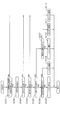
- FIG. 1 is a system diagram illustrating a configuration of a vehicle engine automatic control apparatus according to a first embodiment.
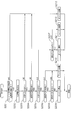
- FIG. 2 is a flowchart illustrating an engine automatic stop / restart control process according to the first embodiment.
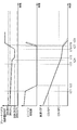
- FIG. 3 is a time chart showing the operation of the setting process of the coast stop permission lower limit value during the coast running of the first embodiment.
- FIG. 4 is a flowchart illustrating an engine automatic stop / restart control process according to the second embodiment.
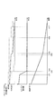
- FIG. 5 is a time chart illustrating the operation of the setting process of the coast stop permission upper limit value and the lower limit value during coast running according to the second embodiment.
- FIG. 6 is a flowchart illustrating an engine automatic stop / restart control process according to the third embodiment.
- FIG. 1 is a system diagram illustrating a configuration of a vehicle engine automatic control apparatus according to a first embodiment.
- FIG. 2 is a flowchart illustrating an engine automatic stop / restart control process according to the first embodiment.
- FIG. 3 is a time chart
- FIG. 7 is a time chart showing the operation of the setting process of the coast stop permission upper limit value and the lower limit value during the coast running of the third embodiment.
- FIG. 8 is a flowchart illustrating an engine automatic stop / restart control process according to the fourth embodiment.
- FIG. 9 is a time chart showing the operation of the setting process of the coast stop permission upper limit value and the lower limit value during the coast running of the fourth embodiment.
- FIG. 1 is a system diagram showing the configuration of the vehicle automatic engine control apparatus according to the first embodiment.
- a torque converter 2 is provided on the output side of the engine 1 which is an internal combustion engine.
- a belt type continuously variable transmission (CVT) 3 is connected to the output side of the torque converter 2.
- the rotational driving force output from the engine 1 is input to the belt-type continuously variable transmission 3 via the torque converter 2, and is transmitted to the drive wheels 4 after being shifted by a desired gear ratio.
- CVT continuously variable transmission
- the engine 1 is provided with a starter 1a for starting the engine and an alternator 1b for generating power.
- the starter 1a is provided with a starter motor.
- the starter 1a drives the starter motor using the power supplied from the in-vehicle battery 1c based on the engine start command, and performs engine cranking. Further, when the fuel is injected and then the engine 1 can rotate independently, the starter motor is stopped.
- the alternator 1b generates power by being rotationally driven by the engine 1, and supplies the generated power to the battery 1c and the like.
- the torque converter 2 amplifies the torque at a low vehicle speed and has a lock-up clutch.
- a predetermined vehicle speed CSVSP1 for example, about 14 km / h
- the lock-up clutch is engaged to connect the output shaft of the engine 1 and the belt.
- the relative rotation with the input shaft of the continuously variable transmission 3 is restricted.
- the belt-type continuously variable transmission 3 includes a starting clutch, a primary pulley and a secondary pulley, and a belt stretched over these pulleys, and achieves a desired gear ratio by changing the pulley groove width by hydraulic control. .
- An oil pump 30 driven by the engine 1 is provided in the belt type continuously variable transmission 3. When the engine is operated, the oil pump 30 is used as a hydraulic pressure source to supply the converter pressure of the torque converter 2 and the lockup clutch pressure, and the pulley pressure and clutch engagement pressure of the belt type continuously variable transmission 3 are supplied.
- the belt type continuously variable transmission 3 is provided with an electric oil pump 31.
- the electric oil pump 31 When the oil pressure cannot be supplied by the oil pump 30 due to the automatic engine stop, the electric oil pump 31 is operated and the necessary oil pressure can be supplied to each actuator. Therefore, even when the engine is stopped, the hydraulic oil leakage can be compensated and the clutch engagement pressure can be maintained.
- the operating state of the engine 1 is controlled by an engine control unit (ECU) 10.
- the engine control unit 10 includes a brake signal from a brake switch 11 that outputs an ON signal by a driver's brake pedal operation, an accelerator signal from an accelerator pedal opening sensor 12 that detects a driver's accelerator pedal operation amount, A brake operation amount signal (master cylinder pressure) from the master cylinder pressure sensor 13 that detects the master cylinder pressure generated based on the brake pedal operation amount, and a wheel speed (from the wheel speed) from the wheel speed sensor 14 provided for each wheel.
- a CVT state signal from a CVT control unit (CVT CU) 20 to be described later, and signals such as engine water temperature, crank angle, and engine speed.
- the engine control unit 10 starts or automatically stops the engine 1 based on the various signals.
- a sensor for detecting the brake pedal stroke amount and the brake pedal depression force a sensor for detecting the wheel cylinder pressure, or the like may be used. That is, by detecting the brake pedal operation amount (brake operation amount) using these sensors, the driver's intention to perform the brake operation may be detected, and the present invention is not limited to the master cylinder pressure sensor 13. .
- the CVT control unit 20 transmits / receives an engine operation state signal and a CVT state signal to / from the engine control unit 10, and controls a gear ratio of the belt type continuously variable transmission 3 based on these signals.
- the start clutch is engaged
- the gear ratio is determined from the gear ratio map based on the accelerator pedal opening and the vehicle speed, and each pulley pressure is controlled.
- the lockup clutch is released, and when the vehicle speed is equal to or higher than the predetermined vehicle speed CSVSP1, the lockup clutch is engaged, so that the engine 1 and the belt type continuously variable transmission 3 are directly connected.
- the electric oil pump 31 is operated to ensure the necessary hydraulic pressure.
- the vehicle automatic engine control apparatus (engine control unit 10) according to the first embodiment stops engine idling when a predetermined condition (various conditions such as the brake pedal being fully depressed) is satisfied when the vehicle is stopped.
- the so-called idling stop control is performed.
- idling stop control since a well-known structure should just be implemented suitably, detailed description is abbreviate
- the coast to stop the engine 1 Perform stop control.
- fuel consumption can be improved if the fuel at the time of resuming fuel injection can be further suppressed in the above-described process in which fuel injection is once resumed from the running state in which fuel injection has been stopped and the engine is stopped again. It becomes possible. Therefore, in the coast stop control of the first embodiment, when a predetermined condition is satisfied, the fuel injection is not restarted, the engine 1 is kept stopped (fuel injection or the like is not performed), and normal idling is performed after the vehicle stops. Transition to stop control is possible.
- One condition when performing coast stop control is that the brake pedal operation amount of the driver is within a predetermined range.
- the reason for setting the brake pedal operation amount as one of the conditions is that the start or end (stop) of the coast stop control should be performed based on the driver's braking intention. In other words, if the brake pedal operation amount is equal to or greater than a predetermined value, the driver's intention to brake can be inferred, and there is a high possibility that the vehicle will stop and shift to idling stop control.
- Start stop control After the coast stop control is started, if the brake pedal operation amount decreases and falls below the predetermined value, the driver's non-braking intention (intention to continue running) can be inferred. End (stop) control.
- the predetermined value is provided as the threshold value of the brake pedal operation amount for restarting the engine after stopping the engine (ending the coast stop control).
- a second threshold value is provided. That is, after the coast stop control is started, the engine 1 is restarted when the brake pedal operation amount increases and becomes equal to or greater than the second threshold value.
- the brake pedal operation amount threshold value as a condition for starting and ending the coast stop control is separately provided on the brake pedal operation amount decrease side and the increase side, and the brake pedal operation amount is sandwiched between the above two threshold values.
- the reason for providing the second threshold is as follows. (1) In a vehicle having a brake master back that boosts the operating force of the brake pedal using the negative pressure generated by the rotation of the engine 1, the engine is stopped when the brake pedal operation amount increases during coast stop control. If the operation is continued, the negative pressure generated by the engine rotation cannot be used, so that the braking force intended by the driver may not be sufficiently obtained.
- the engine stop determination threshold value (the upper limit value BRKIN of the brake pedal operation amount permitting the coast stop control) is set in consideration of the above circumstances (not limited to all but may be a part).
- the engine 1 is stopped when the brake pedal operation amount falls below the threshold value (upper limit value BRKIN), and the engine 1 is restarted when the brake pedal operation amount becomes equal to or greater than the threshold value (upper limit value BRKIN).
- predetermined value lower limit value
- the driver's brake pedal operation amount fluctuates during deceleration traveling toward the stop, and the brake pedal operation amount tends to decrease as the vehicle speed decreases.
- the brake pedal operation amount tends to decrease as the vehicle speed decreases.
- the brake fluid pressure required for deceleration decreases as the vehicle speed decreases, so the driver decreases the brake pedal operation amount.
- the engine 1 is inadvertently restarted in accordance with the decrease in the brake pedal operation amount, the engine 1 is restarted against the driver's intention to stop, and the fuel consumption may not be sufficiently improved. is there.
- the engine start determination threshold value (the lower limit value BRKOUT of the brake pedal operation amount allowing the coast stop control) is set in consideration of the above circumstances.
- the engine 1 is stopped when the brake pedal operation amount becomes equal to or greater than the threshold value (lower limit value BRKOUT), and the engine 1 is restarted when the brake pedal operation amount falls below the threshold value (lower limit value BRKOUT).
- hysteresis may be provided for the upper limit value BRKIN and the lower limit value BRKOUT.
- FIG. 2 is a flowchart showing an engine automatic stop / restart control process executed by the engine control unit 10 according to the first embodiment. This process is repeatedly executed at predetermined intervals during traveling. Whether or not the vehicle is traveling is determined, for example, based on whether or not the vehicle speed VSP is equal to or less than a predetermined value VSP0 representing the vehicle stop state.
- the predetermined value VSP0 may be zero, may be an extremely low vehicle speed range of about 1 to 2 km / h, and may be any value that can be determined as almost stopping the vehicle. Note that other conditions that do not appear in this flowchart may be additionally set as appropriate.
- step S101 it is determined whether or not the permission condition for engine automatic stop / restart control is satisfied, specifically, whether or not the vehicle is in a coasting state (the accelerator pedal operation amount is zero) and the brake pedal is operated. To do.
- the process proceeds to step S102, and otherwise, the process proceeds to step S112 and the engine operating state is continued.
- step S102 the vehicle speed VSP, the brake pedal operation amount (master cylinder pressure) BRKP, the upper limit value (idling stop permission upper limit value) and lower limit value (idling stop permission lower limit value) of the brake pedal operation amount BRKP that permits idling stop control,
- the upper limit value (coast stop permission upper limit value BRKIN) and lower limit value (coast stop permission lower limit value BRKOUT) of the brake pedal operation amount BRKP permitting the coast stop control are read, and the process proceeds to step S103.
- the vehicle speed VSP may be an average value of each wheel speed detected by the wheel speed sensor 14 or may be an average value of the driven wheel speed, and is not particularly limited.
- the idling stop permission upper limit value is a value preset in the system, and is a fixed value in the first embodiment.
- the coast stop permission upper limit value BRKIN is a value preset in the system, and is set to a fixed value BRKINH in the first embodiment.
- the coast stop permission lower limit value BRKOUT is set smaller as the vehicle speed VSP is lower.
- the coast stop permission lower limit value BRKOUT the high vehicle speed zone coast stop permission lower limit value BRKOUTH used when the vehicle speed VSP is high (CSVSP2 ⁇ VSP ⁇ CSVSP1) and the vehicle speed VSP are low (VSP0 ⁇ VSP ⁇ CSVSP2).
- the low vehicle speed zone coast stop permission lower limit value BRKOUTL is set to a value smaller than the high vehicle speed range coast stop permission lower limit value BRKOUTH (BRKOUTL ⁇ BRKOUTH ⁇ BRKINH).
- the idling stop permission lower limit value is set to a value larger than the coast stop permission lower limit value BRKOUT (for example, BRKOUTL).
- BRKOUT for example, BRKOUTL
- the idling stop is performed when the vehicle is stopped.
- the creep torque is output, but when the braking force by the brake is low, the vehicle is inadvertently caused by the creep torque. This is because it may move.
- the coast stop state is during vehicle deceleration (that is, during travel). In this state, the aim is to improve the fuel efficiency by stopping the engine as much as possible. Even if the engine 1 is restarted before the vehicle stops, the driver feels a pop-out feeling due to creep torque if the vehicle is running. Because it is difficult.
- step S103 it is determined whether or not the vehicle speed VSP is below an upper limit value CSVSP1 that permits coast stop control.
- the process proceeds to step S104. Otherwise, the process proceeds to step S112, and the engine operating state is continued.
- step S104 it is determined whether or not the brake pedal operation amount BRKP is below the coast stop permission upper limit value BRKINH. When the value falls below the upper limit value BRKINH, the process proceeds to step S105, and otherwise, the process proceeds to step S112, and the engine operating state is continued.
- step S105 it is determined whether or not the vehicle speed VSP falls below a predetermined value CSVSP2 set to be smaller than the coast stop permission upper limit CSVSP1.
- the predetermined value CSVSP2 is a vehicle speed threshold value for switching between the high vehicle speed zone coast stop permission lower limit value BRKOUTH and the low vehicle speed zone coast stop permission lower limit value BRKOUTL by determining whether the vehicle speed is high or low. is there.
- step S106 it is determined whether or not the brake pedal operation amount BRKP is below the low vehicle speed zone coast stop permission lower limit value BRKOUTL.
- the routine proceeds to step S109 and the engine is restarted. Otherwise, the routine proceeds to step S108 and the engine is stopped.
- step S107 it is determined whether or not the brake pedal operation amount BRKP is below the high vehicle speed zone coast stop permission lower limit value BRKOUTH.
- the routine proceeds to step S111 to restart the engine, and otherwise, the routine proceeds to step S110 to stop the engine.
- FIG. 3 is a time chart showing the operation of the setting process of the coast stop permission lower limit value BRKOUT during the coast running of the first embodiment.
- the driving state (precondition) at the first time in the time chart is a coasting driving state in which the driver releases his / her foot from the accelerator pedal during driving.
- the driver Before time t11, the driver has stepped on the brake pedal and satisfies the permission condition for engine automatic stop / restart control, but the vehicle speed VSP is equal to or greater than the coast stop permission upper limit CSVSP1. Therefore, in the control process of FIG. 2, the process proceeds from step S101 to S102 to S103 to S112, and coast stop control is not performed.
- the engine 1 continues to operate.
- the brake pedal operation amount BRKP of the driver (solid line in FIG. 3) gradually decreases.
- the vehicle speed VSP falls below the coast stop permission upper limit CSVSP1 (CSVSP2 ⁇ VSP ⁇ CSVSP1). Further, the brake pedal operation amount BRKP falls below the coast stop permission upper limit value BRKINH (two-dot chain line in FIG. 3) (BRKOUTH ⁇ BRKP ⁇ BRKINH). Therefore, the flow proceeds to steps S101 ⁇ S102 ⁇ S103 ⁇ S104 ⁇ S105 ⁇ S107 ⁇ S110, and the engine 1 (fuel injection) is stopped. Thus, after the time t11 when the coast stop is started, the engine speed rapidly decreases toward zero.
- step S101 ⁇ S102 ⁇ S103 ⁇ S104 ⁇ S105 ⁇ S106 the coast stop permission lower limit value BRKOUT (the one-dot chain line in FIG. 3) is changed from the high vehicle speed range coast stop permission lower limit value BRKOUTH to the low vehicle speed range coast stop permission lower limit. Switch to value BRKOUTL.
- step S106 Since the brake pedal operation amount BRKP is equal to or greater than the low vehicle speed zone coast stop permission lower limit value BRKOUTL (BRKOUTL ⁇ BRKP ⁇ BRKOUTH), the flow proceeds from step S106 to S108, and the engine is stopped.
- the decreasing gradient of the brake pedal operation amount BRKP becomes smaller again. Since the brake pedal operation amount BRKP is still greater than or equal to the low vehicle speed zone coast stop permission lower limit value BRKOUTL (BRKOUTL ⁇ BRKP ⁇ BRKOUTH), the flow proceeds to step S106 ⁇ S108, and the engine is stopped.
- the coast stop permission lower limit value BRKOUT is set to the high vehicle speed zone coast stop permission lower limit value BRKOUTH after time t13 as well as time t13 (broken line in FIG. 3).
- the brake pedal operation amount BRKP falls below the high vehicle speed zone coast stop permission lower limit value BRKOUTH, so the engine 1 is restarted.
- the engine speed increases after time t16. Therefore, in the comparative example, the driver intends to stop and the engine 1 is restarted even though the fuel injection can be stopped by executing the coast stop control. It cannot be improved sufficiently.
- the coast stop permission lower limit value BRKOUT is set to be smaller as the vehicle speed VSP is lower (steps S103 to S107). Therefore, even if the amount of brake operation changes according to the vehicle speed VSP, the engine 1 can be restarted at a more appropriate timing according to the driver's intention, so that fuel efficiency can be further improved.
- Brake operation amount detection means master cylinder pressure sensor 13 for detecting the brake operation amount (master cylinder pressure) of the driver, and during coasting, the engine 1 is stopped based on the detected brake operation amount. After the stop, when the detected brake operation amount falls below the first threshold (coast stop permission lower limit value BRKOUT), the engine stop / restart means (engine control unit 10) for restarting the engine 1 and the lower the vehicle speed VSP, And a first threshold value setting means (steps S103 to S107) for setting the threshold value of 1 to be small.
- first threshold coast stop permission lower limit value BRKOUT
- the engine 1 can be restarted at a more appropriate timing according to the driver's intention, so that fuel efficiency can be further improved.
- the engine stop / restart means (engine control unit 10) is configured so that the detected brake operation amount (master cylinder pressure) is greater than or equal to a second threshold value (coast stop permission upper limit value BRKIN) after the engine is stopped during coasting. Then, the engine 1 is restarted.
- a second threshold value coast stop permission upper limit value BRKIN
- FIG. 4 is a flowchart showing an engine automatic stop / restart control process executed by the engine control unit 10 of the second embodiment.
- Example 2 like the coast stop permission lower limit value BRKOUT, the coast stop permission upper limit value BRKIN is set smaller as the vehicle speed VSP is lower.
- Coast stop permission upper limit value BRKIN is used when the vehicle speed VSP is high (CSVSP2 ⁇ VSP ⁇ CSVSP1) and the high vehicle speed coast stop permission upper limit value BRKINH is low, and when the vehicle speed VSP is low (VSP0 ⁇ VSP ⁇ CSVSP2)
- There is a vehicle speed range coast stop permission upper limit BRKINL There is a vehicle speed range coast stop permission upper limit BRKINL.
- the low vehicle speed zone coast stop permission upper limit value BRKINL is set to a value smaller than the high vehicle speed range coast stop permission upper limit value BRKINH (BRKOUTH ⁇ BRKINL ⁇ BRKINH).
- Steps S201 to S205 are the same as steps S101 to S105 in FIG.
- step S204 it is determined whether or not the brake pedal operation amount BRKP is below a high vehicle speed zone coast stop permission upper limit value BRKINH.
- step S206 it is determined whether or not the brake pedal operation amount BRKP is below the low vehicle speed zone coast stop permission upper limit value BRKINL.
- the process proceeds to step S208, and otherwise, the process proceeds to step S210 and the engine is restarted.
- Step S208 is the same as step S106 in FIG.
- Steps S207 and S209 to S213 are the same as steps S107 and S108 to S112 in FIG. 2, respectively.
- FIG. 5 is a time chart similar to that of the first embodiment (FIG. 3) showing the operation of the setting process of the coast stop permission upper limit value BRKIN and the lower limit value BRKOUT during coast running of the second embodiment.
- the flow proceeds from step S201 ⁇ S202 ⁇ S203 ⁇ S204 ⁇ S205 ⁇ S206, the coast stop permission lower limit value BRKOUT is switched to the low vehicle speed zone coast stop permission lower limit value BRKOUTL, and the coast stop permission upper limit value.
- BRKIN switches from the high vehicle speed zone coast stop permission upper limit value BRKINH to the low vehicle speed range coast stop permission upper limit value BRKINL.
- the flow proceeds from step S206 to S208 to S209. Continue to stop the engine.
- the brake pedal operation amount BRKP becomes equal to or higher than the low vehicle speed zone coast stop permission upper limit value BRKINL (BRKINL ⁇ BRKP ⁇ BRKINH). Therefore, the process proceeds from step S201 ⁇ S202 ⁇ S203 ⁇ S204 ⁇ S205 ⁇ S206 ⁇ S210, and the engine is restarted, so that the engine speed increases after time t27. Further, as the engine speed increases, engine negative pressure is generated and braking force using the brake master back is generated. Therefore, the vehicle speed VSP decreases with a larger gradient and the vehicle decelerates rapidly.
- the coast stop permission upper limit value BRKIN is set to the high vehicle speed zone coast stop permission upper limit value BRKINH after time t23 as well as time t23 (broken line in FIG. 5).
- the brake pedal operation amount BRKP increases. Since the coast stop permission upper limit value BRKIN is set to the high vehicle speed zone coast stop permission upper limit value BRKINH, the brake pedal operation amount BRKP is set to the high vehicle speed at time t28 later than time t27 (engine restart time in the second embodiment). The belt coast stop permission upper limit BRKINH is exceeded and the engine 1 is restarted. As indicated by a broken line in FIG. 5, the engine speed increases after time t28.
- the coast stop permission upper limit value BRKIN is set smaller as the vehicle speed VSP is lower (steps S203 to S206). Therefore, even if the brake operation amount increases when the vehicle speed VSP is low, the engine 1 can be restarted more quickly. Therefore, the negative pressure generation of the engine 1 can be ensured promptly and the brake master back is used. The braking performance of the vehicle can be improved.
- the shift controllability of the belt type continuously variable transmission 3 can be improved.
- the coast stop permission lower limit value BRKOUT is lowered according to the vehicle speed VSP as in the first embodiment, the engine 1 is restarted at a lower vehicle speed, that is, at a time shorter before the vehicle stops.
- the improvement of the shift controllability is particularly effective.
- a stepped transmission may be used as the transmission, and the above-described effects can be obtained as long as the transmission performs a shift using the discharge pressure of a pump (oil pump 30) driven by the engine 1. it can.
- the belt-type continuously variable transmission 3 that needs to supply a relatively high discharge pressure (pulley pressure) for shifting is used, which is particularly effective for improving shift controllability.
- the engine 1 can be operated early so that the influence on these controls can be suppressed.
- step S203 to S206 There is provided second threshold setting means (steps S203 to S206) for setting the second threshold (coast stop permission upper limit value BRKIN) smaller as the vehicle speed VSP is lower.
- FIG. 6 is a flowchart showing an engine automatic stop / restart control process executed by the engine control unit 10 of the third embodiment.
- the coast stop permission upper limit value BRKIN and the coast stop permission lower limit value BRKOUT are set smaller as the vehicle speed VSP is lower.
- the engine control unit 10 has a map 1 indicating the relationship between the coast stop permission upper limit value BRKIN and the vehicle speed VSP, and a map 2 indicating the relationship between the coast stop permission lower limit value BRKOUT and the vehicle speed VSP.
- the boundary is set so that the coast stop permission upper limit value BRKIN decreases stepwise (stepwise) as the vehicle speed VSP changes from the high side to the low side.
- a line is drawn.
- a coast stop permission (OK) region and a coast stop prohibition (NG) region are separated. Whether the coast stop (engine stop) is permitted or not is determined according to which region the driving state (vehicle speed VSP and brake pedal operation amount BRKP) belongs to.
- Map 2 has the same shape as Map 1, and the boundary line is set so that coast stop permission lower limit value BRKOUT decreases stepwise (in steps) as vehicle speed VSP changes from high to low. It is drawn. By this boundary line, a coast stop permission (OK) region and a coast stop prohibition (NG) region are separated.
- BRKOUT coast stop permission lower limit value
- step S301 it is determined whether or not a permission condition for engine automatic stop / restart control is satisfied, specifically, whether or not a condition such as a coasting driving state and a brake pedal being operated is satisfied. If the permission condition is satisfied, the process proceeds to step S302; otherwise, the process proceeds to step S307 and the engine operating state is continued.
- step S302 the vehicle speed VSP, the brake pedal operation amount (master cylinder pressure) BRKP, the upper and lower limits of the brake pedal operation amount BRKP permitting idling stop control, and maps 1 and 2 are read, and the process proceeds to step S303. .
- step S303 it is determined whether the driving state at that time (vehicle speed VSP and brake pedal operation amount BRKP) belongs to the coast stop permission area or the coast stop prohibition area of map 1.
- the process proceeds to Step S304 ⁇ , and when it is determined that it belongs to the coast stop prohibition area, the process proceeds to Step S307 and the engine operating state is continued.
- step S304 it is determined whether the driving state at that time (vehicle speed VSP and brake pedal operation amount BRKP) belongs to the coast stop permission area or the coast stop prohibition area of map 2.
- the routine proceeds to step S305 and the engine is stopped.
- the routine proceeds to step S306 and the engine is restarted.
- FIG. 7 is a time chart similar to that of the first embodiment (FIG. 3) showing the operation of the setting process of the coast stop permission upper limit value BRKIN and the lower limit value BRKOUT during the coasting of the third embodiment.
- step S301 Before time t31, the driver has stepped on the brake pedal, but the conditions for permitting automatic engine stop / restart control are not satisfied. Therefore, the flow proceeds from step S301 to step S307 in the control process of FIG. To do.
- the brake pedal operation amount BRKP of the driver gradually decreases.
- the permission condition for engine automatic stop / restart control is satisfied. Further, the driving state (vehicle speed VSP and brake pedal operation amount BRKP) belongs to the coast stop permission area in map 1 and the coast stop permission area in map 2. Therefore, the flow proceeds to steps S301 ⁇ S302 ⁇ S303 ⁇ S304 ⁇ S305, and the engine 1 (fuel injection) is stopped. After time t31 when the coast stop is started, the engine speed rapidly decreases toward zero.
- the coast stop permission upper limit value BRKIN in map 1 and the lower limit value BRKOUT in map 2 decrease stepwise (stepwise) in accordance with the decrease in vehicle speed VSP.
- the coast stop permission upper limit value BRKIN and the lower limit value BRKOUT in the maps 1 and 2 respectively decrease stepwise (stepwise) in accordance with the decrease in the vehicle speed VSP.
- the driver's brake pedal operation amount BRKP decreases.
- the coast stop permission lower limit value BRKOUT in Map 2 decreases in accordance with the decrease in the vehicle speed VSP, the brake pedal operation amount BRKP is suppressed from falling below the coast stop permission lower limit value BRKOUT.
- the driving state (vehicle speed VSP and brake pedal operation amount BRKP) remains in the coast stop permission area in map 2. Therefore, the flow proceeds to steps S301 ⁇ S302 ⁇ S303 ⁇ S304 ⁇ S305, and the engine stop is continued.
- the coast stop permission upper limit value BRKIN in the map 1 decreases as the vehicle speed VSP decreases. If the driver depresses the brake pedal, then the brake pedal operation amount BRKP becomes relatively fast. It tends to be over the coast stop permission upper limit BRKIN. In other words, the driving state (vehicle speed VSP and brake pedal operation amount BRKP) easily shifts from the coast stop permission area to the prohibition area in map 1. Therefore, the engine restart is performed more promptly.
- a plurality of coast stop permission lower limit values BRKOUT are set so as to decrease as the vehicle speed VSP decreases.
- the coast stop permission lower limit value BRKOUT is set to 3 or more unlike the first and second embodiments (two of the high vehicle speed zone coast stop permission lower limit value BRKOUTH and the low vehicle speed zone coast stop permission lower limit value BRKOUTL). .
- the coast stop permission lower limit value BRKOUT is prevented from changing rapidly, and the engine 1 is restarted at a more appropriate timing. be able to. Therefore, fuel consumption can be further improved.
- multiple coast stop permission upper limit values BRKIN are set so as to decrease as the vehicle speed VSP decreases.
- the coast stop permission upper limit value BRKIN is set to 3 or more, unlike the second embodiment (two of the high vehicle speed zone coast stop permission upper limit value BRKINH and the low vehicle speed zone coast stop permission upper limit value BRKINL).
- the coast stop permission upper limit value BRKIN is prevented from changing rapidly, and the engine 1 is restarted at a more appropriate timing. be able to. Therefore, the braking performance of the vehicle and the shift controllability of the belt type continuously variable transmission 3 can be further improved.
- Example 3 in addition to the above (1) to (3), the following effects can be obtained.
- the first threshold value setting means sets a plurality of first threshold values (coast stop permission lower limit value BRKOUT) so as to decrease as the vehicle speed VSP decreases.
- the first threshold setting means sets the first threshold (coast stop permission lower limit BRKOUT) based on a predetermined map (map 2).
- the second threshold value setting means sets a plurality of second threshold values (coast stop permission upper limit value BRKIN) so as to decrease as the vehicle speed VSP decreases.
- the second threshold value setting means sets the second threshold value (coast stop permission upper limit value BRKIN) based on a predetermined map (Map 1).
- FIG. 8 is a flowchart illustrating an engine automatic stop / restart control process executed by the engine control unit 10 of the fourth embodiment.
- the engine control unit 10 uses a calculation formula 1 for calculating the coast stop permission upper limit value BRKIN smaller as the vehicle speed VSP becomes lower and a calculation formula 2 for calculating the coast stop permission lower limit value BRKOUT smaller as the vehicle speed VSP becomes lower.
- the coast stop permission upper limit value BRKIN and the lower limit value BRKOUT are calculated based on VSP.
- the calculation formulas 1 and 2 can have, for example, a characteristic in which the upper limit value BRKIN or the lower limit value BRKOUT is linearly decreased as the vehicle speed VSP decreases.
- Step S401 is the same as step S301 in FIG.
- step S402 the vehicle speed VSP, the brake pedal operation amount (master cylinder pressure) BRKP, and the brake pedal operation amount BRKP for which the idling stop control is permitted are read, and the process proceeds to step S403.
- a coast stop permission upper limit value BRKIN is calculated based on the read vehicle speed VSP and Formula 1, and it is determined whether or not the read brake pedal operation amount BRKP is below the coast stop permission upper limit value BRKIN.
- the coasting stop permission (OK) region in which the driving state at that time (vehicle speed VSP and brake pedal operation amount BRKP) is classified by the characteristics of the coast stop permission upper limit value BRKIN (expressed in Formula 1) It is determined which of the coast stop prohibition (NG) areas it belongs to.
- step S404 If it is determined that the brake pedal operation amount BRKP falls below the coast stop permission upper limit value BRKIN (belongs to the coast stop permission area), the process proceeds to step S404, and the brake pedal operation amount BRKP is greater than or equal to the coast stop permission upper limit value BRKIN (coast stop). If it is determined that it belongs to the prohibited area, the process proceeds to step S407 and the engine operating state is continued.
- a coast stop permission lower limit value BRKOUT is calculated based on the read vehicle speed VSP and Formula 2, and it is determined whether or not the read brake pedal operation amount BRKP is below the coast stop permission lower limit value BRKOUT.
- the coasting stop permission (OK) region in which the driving state at that time (vehicle speed VSP and brake pedal operation amount BRKP) is classified by the characteristics of the coast stop permission lower limit BRKOUT (expressed in Formula 2) It is determined which of the coast stop prohibition (NG) areas it belongs to.
- step S406 When it is determined that the brake pedal operation amount BRKP is below the coast stop permission lower limit value BRKOUT (belonging to the coast stop prohibition region), the routine proceeds to step S406 and the engine is restarted, and the brake pedal operation amount BRKP is the coast stop permission lower limit value BRKOUT. If it is determined as above (belonging to the coast stop permission area), the process proceeds to step S405 to stop the engine.
- FIG. 9 is a time chart similar to that of the first embodiment (FIG. 3) showing the operation of the setting process of the coast stop permission upper limit value BRKIN and the lower limit value BRKOUT during coast running of the fourth embodiment.
- the permission condition for the engine automatic stop / restart control is satisfied. Further, the brake pedal operation amount BRKP is less than the coast stop permission upper limit value BRKIN calculated by the vehicle speed VSP and the calculation formula 1, and is equal to or more than the coast stop permission lower limit value BRKOUT calculated by the vehicle speed VSP and the calculation formula 2. Therefore, the flow proceeds to steps S401 ⁇ S402 ⁇ S403 ⁇ S404 ⁇ S405, and the engine is stopped. After the time t41 when the coast stop is started, the engine speed rapidly decreases toward zero.
- the brake pedal operation amount BRKP decreases.
- the coast stop permission lower limit value BRKOUT decreases as the vehicle speed VSP decreases, and therefore, the brake pedal operation amount BRKP is suppressed from falling below the coast stop permission lower limit value BRKOUT.
- the driving state (vehicle speed VSP and brake pedal operation amount BRKP) remains in the coast stop permission area. Therefore, the process proceeds to steps S401 ⁇ S402 ⁇ S403 ⁇ S404 ⁇ S405, and the engine is stopped.
- the coast stop permission upper limit value BRKIN decreases as the vehicle speed VSP decreases. If the driver depresses the brake pedal, then the brake pedal operation amount BRKP is relatively early and the coast stop permission is permitted. It tends to be higher than the upper limit value BRKIN. In other words, the driving state (vehicle speed VSP and brake pedal operation amount BRKP) easily shifts from the coast stop permission area to the prohibition area. Therefore, the engine restart is performed more promptly.
- the coast stop permission upper limit value BRKIN and the coast stop permission lower limit value BRKOUT are set based on the calculation formulas 1 and 2, respectively. Therefore, for example, the amount of data stored in the engine control unit 10 can be reduced as compared with the case where the upper limit value BRKIN and the lower limit value BRKOUT are set using a map. That is, if the upper limit value BRKIN and the lower limit value BRKOUT are set more finely according to the vehicle speed VSP, the amount of data increases when the map is used, but if the calculation formula is used, the increase in the amount of data is suppressed. Can do.
- Example 4 in addition to the above (1) to (4) and (6), the following effects can be obtained.
- the first threshold value setting means sets the first threshold value (coast stop permission lower limit value BRKOUT) based on a predetermined calculation formula (calculation formula 2).
- the second threshold value setting means sets the second threshold value (coast stop permission upper limit value BRKIN) based on a predetermined calculation formula (calculation formula 1).
- the vehicle speed VSP that is a threshold value for changing the coast stop permission upper limit value BRKIN does not have to be the same as the vehicle speed VSP that is the threshold value for changing the coast stop permission lower limit value BRKOUT. It is good also as making it differ.
- the coast stop permission upper limit value BRKIN may not be changed according to the vehicle speed VSP.
Abstract
運転者のブレーキ操作量(BRKP)を検出するブレーキ操作量検出手段と、コースト走行中、検出されたブレーキ操作量(BRKP)に基づきエンジンを停止し、エンジン停止後に、検出されたブレーキ操作量(BRKP)が第1の閾値を下回るとエンジンを再始動するエンジン停止再始動手段(エンジンコントロールユニット) と、車速(VSP)が低いほど第1の閾値を小さく設定する第1の閾値設定手段とを設けた。
Description
本発明は、走行中にエンジンを自動的に停止、再始動するエンジン自動制御装置に関する。
車両のエンジン自動制御装置として、JP4374805Bに記載の技術が開示されている。この装置は、車両走行中であっても、ブレーキ操作量がエンジン停止判定閾値以上となったときはエンジンを停止して燃費の向上を図り、ブレーキ操作量がエンジン始動判定閾値以下となったときはエンジンを再始動する。
上記従来の装置は、車両が走行状態であると判定される所定車速以上では、車速に関わらずエンジン(再)始動判定閾値が固定される構成であるため、停車に向けた減速走行中、運転者の意図に反してエンジンが再始動され、燃費を十分に向上することができないおそれがあった。例えば、停車に向けた減速走行中、運転者のブレーキ操作量は変動し、車速が低くなるほどブレーキ操作量は小さくなりがちである。しかし、車速に関わりなくエンジン始動判定閾値が設定されていると、ブレーキ操作量が容易にエンジン始動判定閾値以下となってエンジンが再始動するおそれがある。
本発明は、上記問題に着目してなされたもので、燃費をより向上できる車両のエンジン自動制御装置を提供することを目的とする。
一実施形態における車両のエンジン自動制御装置では、車速が低いほど、エンジン始動判定閾値を小さく設定する。
本発明の実施形態、本発明の利点については、添付された図面とともに以下に詳細に説明される。
図1は、実施例1の車両のエンジン自動制御装置の構成を表すシステム図である。内燃機関であるエンジン1の出力側には、トルクコンバータ2が設けられている。トルクコンバータ2の出力側には、ベルト式無段変速機(CVT)3が接続されている。エンジン1から出力された回転駆動力は、トルクコンバータ2を介してベルト式無段変速機3に入力され、所望の変速比によって変速された後、駆動輪4に伝達される。
エンジン1には、エンジン始動を行う始動装置1aと、発電を行うオルタネータ1bとが備えられている。始動装置1aにはスタータモータが備えられている。始動装置1aは、エンジン始動指令に基づき、車載バッテリ1cの供給する電力を用いてスタータモータを駆動し、エンジンクランキングを行う。また、燃料を噴射し、その後、エンジン1が自立回転可能となると、スタータモータを停止する。オルタネータ1bは、エンジン1により回転駆動されることで発電し、発電した電力をバッテリ1c等に供給する。
トルクコンバータ2は、低車速時にトルク増幅を行うと共に、ロックアップクラッチを有しており、所定車速CSVSP1(例えば14km/h程度)以上では、ロックアップクラッチを締結してエンジン1の出力軸とベルト式無段変速機3の入力軸との相対回転を規制する。
ベルト式無段変速機3は、発進クラッチと、プライマリプーリ及びセカンダリプーリと、これらプーリに掛け渡されたベルトから構成され、プーリ溝幅を油圧制御によって変更することで所望の変速比を達成する。また、ベルト式無段変速機3内には、エンジン1によって駆動されるオイルポンプ30が設けられている。エンジン作動時には、このオイルポンプ30を油圧源として、トルクコンバータ2のコンバータ圧やロックアップクラッチ圧を供給し、また、ベルト式無段変速機3のプーリ圧やクラッチ締結圧を供給する。
更に、ベルト式無段変速機3には電動オイルポンプ31が設けられている。エンジン自動停止によってオイルポンプ30による油圧供給ができない場合には、電動オイルポンプ31が作動し、必要な油圧を各アクチュエータに供給可能に構成されている。よって、エンジン停止時であっても、作動油のリークを補償し、また、クラッチ締結圧を維持することができる。
エンジン1は、エンジンコントロールユニット(ECU)10によって作動状態が制御される。エンジンコントロールユニット10には、運転者のブレーキペダル操作によりオン信号を出力するブレーキスイッチ11からのブレーキ信号と、運転者のアクセルペダル操作量を検出するアクセルペダル開度センサ12からのアクセル信号と、ブレーキペダル操作量に基づいて生じるマスタシリンダ圧を検出するマスタシリンダ圧センサ13からのブレーキ操作量信号(マスタシリンダ圧)と、各輪に備えられた車輪速センサ14からの車輪速(車輪速から車速を検出する場合には車速信号と同義)と、後述するCVTコントロールユニット(CVT CU)20からのCVT状態信号と、エンジン水温、クランク角、エンジン回転数等の信号とを入力する。エンジンコントロールユニット10は、上記各種信号に基づいて、エンジン1の始動または自動停止を実施する。
尚、マスタシリンダ圧センサ13に代えて、ブレーキペダルストローク量やブレーキペダル踏力を検出するセンサ、またはホイルシリンダ圧を検出するセンサ等を用いてもよい。すなわち、これらのセンサを用いてブレーキペダル操作量(ブレーキ操作量)を検出することで、運転者の制動操作意図を検出するようにしてもよく、マスタシリンダ圧センサ13に限定されることはない。
CVTコントロールユニット20は、エンジンコントロールユニット10との間でエンジン作動状態とCVT状態の信号を送受信し、これら信号に基づいて、ベルト式無段変速機3の変速比等を制御する。具体的には、走行レンジが選択されているときは、発進クラッチの締結を行うと共に、アクセルペダル開度と車速とに基づいて変速比マップから変速比を決定し、各プーリ圧を制御する。また、車速が所定車速CSVSP1未満のときは、ロックアップクラッチを解放し、所定車速CSVSP1以上のときはロックアップクラッチを締結し、エンジン1とベルト式無段変速機3とを直結状態とする。更に、走行レンジ選択中におけるエンジン自動停止時には、電動オイルポンプ31を作動させ、必要な油圧を確保する。
(エンジン自動制御処理)
次に、エンジン自動制御処理について説明する。本実施例1の車両のエンジン自動制御装置(エンジンコントロールユニット10)は、車両停止時に、所定の条件(ブレーキペダルが十分に踏み込まれているといった各種条件)が成立したときは、エンジンアイドリングを停止する、いわゆるアイドリングストップ制御を行う。尚、アイドリングストップ制御については周知の構成を適宜実施すればよいため、詳細な説明は省略する。加えて、車両走行中であっても、減速中であり、減速燃料カット制御を経て、このまま車両停止してアイドリングストップ制御に移行する可能性が高いと判断したときは、エンジン1を停止するコーストストップ制御を行う。
次に、エンジン自動制御処理について説明する。本実施例1の車両のエンジン自動制御装置(エンジンコントロールユニット10)は、車両停止時に、所定の条件(ブレーキペダルが十分に踏み込まれているといった各種条件)が成立したときは、エンジンアイドリングを停止する、いわゆるアイドリングストップ制御を行う。尚、アイドリングストップ制御については周知の構成を適宜実施すればよいため、詳細な説明は省略する。加えて、車両走行中であっても、減速中であり、減速燃料カット制御を経て、このまま車両停止してアイドリングストップ制御に移行する可能性が高いと判断したときは、エンジン1を停止するコーストストップ制御を行う。
すなわち、運転者がアクセルペダルを操作することなく惰性走行している、いわゆるコースト走行状態(ブレーキペダル操作をしている状態を含む)のときには、燃料噴射を停止する。この減速燃料カット制御中は、燃料噴射を停止するとともに、駆動輪4から伝達されるコーストトルクによってロックアップクラッチを介してエンジン回転数を維持する。しかし、所定車速CSVSP1まで減速するとロックアップクラッチは解放されるため、燃料噴射しなければエンジン1は停止してしまう。そこで、従来は、ロックアップクラッチが解放されるタイミングで減速燃料カット制御を中止して燃料噴射を再開し、エンジン自立回転を維持すると共に、その後、車両が完全停止した後、エンジンアイドリングを停止するようにしていた。しかし、このように燃料噴射を停止した走行状態から、一旦燃料噴射を再開し、再度エンジン停止を行う上記過程において、燃料噴射再開時の燃料を更に抑制することができれば、燃費を改善することが可能となる。そこで、本実施例1のコーストストップ制御では、所定の条件が成立すると、燃料噴射を再開することなく、エンジン1を停止したままとし(燃料噴射等を行わず)、車両停止後は通常のアイドリングストップ制御にそのまま移行可能とした。
コーストストップ制御を行う際の1つの条件は、運転者のブレーキペダル操作量が所定範囲内であることとした。ブレーキペダル操作量を条件の1つとした理由は、コーストストップ制御の開始または終了(中止)は、運転者の制動意図に基づいて行うべきものだからである。すなわち、ブレーキペダル操作量が所定値以上であれば、運転者の制動意図を推認でき、このまま車両停止してアイドリングストップ制御に移行する可能性が高いため、作動中のエンジン1を停止してコーストストップ制御を開始する。コーストストップ制御開始後、ブレーキペダル操作量が減少して上記所定値を下回ると、運転者の非制動意図(走行継続の意図)を推認できるため、停止中のエンジン1を再始動してコーストストップ制御を終了(中止)する。
また、実施例1では、エンジン停止後にエンジン再始動を行う(コーストストップ制御を終了する)ためのブレーキペダル操作量の閾値として、上記所定値(ブレーキペダル操作量の減少側の閾値)のみを設けるのではなく、上記所定値よりも大きな第2の閾値(ブレーキペダル操作量の増加側の閾値)を設ける。すなわち、コーストストップ制御開始後、ブレーキペダル操作量が増加して第2の閾値以上になると、エンジン1を再始動する。このように、コーストストップ制御を開始・終了する条件としてのブレーキペダル操作量の閾値を、ブレーキペダル操作量の減少側と増加側とで別々に設け、ブレーキペダル操作量が上記2つの閾値に挟まれる所定範囲内(第2の閾値=上限値と上記所定値=下限値との間)であるときに、コーストストップ制御を行うこととした。
第2の閾値(上限値)を設けたのは以下の諸理由による。
(1) エンジン1の回転により発生する負圧を利用してブレーキペダルの操作力を倍力するブレーキマスターバックを備える車両においては、コーストストップ制御中にブレーキペダル操作量が増大した場合、エンジン停止を継続すると、エンジン回転による負圧を利用できないため、運転者が意図する制動力を十分に得られないおそれがある。
(1) エンジン1の回転により発生する負圧を利用してブレーキペダルの操作力を倍力するブレーキマスターバックを備える車両においては、コーストストップ制御中にブレーキペダル操作量が増大した場合、エンジン停止を継続すると、エンジン回転による負圧を利用できないため、運転者が意図する制動力を十分に得られないおそれがある。
(2)ブレーキペダルを強く踏んでいるときは、急減速しているときであり、車両停止に至るまでの時間が短いと考えられる。このとき、車両が停止するまでの間(すなわち駆動輪4が回転しており、変速機が変速可能な間)に変速機(ベルト式無段変速機3)の変速比を発進時の低速段(最Low側)まで変速する必要がある。エンジン1により駆動されるオイルポンプ30の吐出圧を利用して変速を行う変速機を備えた車両においては、上記のように車両が停止するまでの間に素早く変速するために、オイルポンプ30の吐出量を確保する必要がある。特に、ベルト式無段変速機3の変速には、比較的高いプーリ圧の供給を要する。したがって、オイルポンプ30の駆動源であるエンジン1の停止は好ましくない。尚、電動オイルポンプ31が供給する油圧により変速を行うことも考えられるが、変速を素早く行うためには、電動オイルポンプ31を大型化する必要があり、好ましくない。
(3)急減速時には、車両挙動を安定化するための各種の制御が介入することも考えられる。例えば、車輪ロックを回避するためのABS制御では、車輪に作用するブレーキ液圧を増減するにあたり、エンジン1側からのトルク入力も加味した上で種々のゲイン等が制御ロジックに設定される。また、スリップ量が多い場合には、エンジントルクを抑制するトラクションコントロールシステム等が作動するおそれもある。よって、不用意にエンジン停止を行うと、これら制御への影響も懸念される。
よって、上記諸事情(全てに限らず一部でもよい)を考慮したエンジン停止判定閾値(コーストストップ制御を許可するブレーキペダル操作量の上限値BRKIN)を設定する。ブレーキペダル操作量が上記閾値(上限値BRKIN)を下回るとエンジン1を停止し、ブレーキペダル操作量が上記閾値(上限値BRKIN)以上になるとエンジン1を再始動する。
減少側の閾値(上記所定値=下限値)について検討すると、ブレーキペダルを緩やかに踏み込んでいる緩減速時には、そのまま車両停止する場合と、再度ブレーキペダルを解放し、再発進する場合とが考えられる。例えば、渋滞を走行しているときに、ブレーキペダルを緩やかに操作して走行状態を継続することなどが考えられる。この場合、不用意にエンジン1を停止すると、エンジン1が発生するクリープトルクを利用することができず、またエンジン停止と再始動とが繰り返され、運転者に違和感を与えるおそれがある。
また、エンジン停止後、ブレーキペダルが緩やかに踏まれた状態でエンジン再始動すると、エンジントルクが駆動輪4に出力されることで飛び出し感を与えるおそれもある。一方、上り勾配では、エンジン再始動するブレーキペダル操作量の閾値が低すぎると、ブレーキペダルによる制動力が小さくなってからエンジン再始動するため、車両が若干後退するおそれがある。
更に、停車に向けた減速走行中、運転者のブレーキペダル操作量は変動し、車速が低くなるほどブレーキペダル操作量は小さくなりがちである。例えば、赤信号で止まろうとするとき等、ゆっくり停車したい場合には、低車速になるほど減速に必要なブレーキ液圧は小さくなるため、運転者はブレーキペダル操作量を小さくする。ここで、ブレーキペダル操作量の減少に応じて不用意にエンジン1を再始動すると、運転者の停車意図に反してエンジン1を再始動することとなり、燃費を十分に向上することができないおそれがある。
よって、上記諸事情を考慮したエンジン始動判定閾値(コーストストップ制御を許可するブレーキペダル操作量の下限値BRKOUT)を設定する。ブレーキペダル操作量が上記閾値(下限値BRKOUT)以上になるとエンジン1を停止し、ブレーキペダル操作量が上記閾値(下限値BRKOUT)を下回るとエンジン1を再始動する。
尚、エンジン停止と再始動の切換えが頻繁に行われることを抑制するため、上記上限値BRKINと下限値BRKOUTにそれぞれヒステリシスを設けることとしてもよい。
〔エンジン自動停止再始動制御処理〕
図2は、実施例1のエンジンコントロールユニット10にて実行されるエンジン自動停止再始動制御処理を表すフローチャートである。この処理は、走行中、所定周期毎に繰り返し実行される。車両が走行中であるか否かは、例えば、車速VSPが車両停止状態を表す所定値VSP0以下か否かにより判断する。所定値VSP0はゼロでもよいし、1~2km/h程度の極低車速領域であってもよく、ほぼ車両停止と判断できる値であればよい。尚、本フローチャートに現れない他の条件等を適宜追加設定してもよい。
図2は、実施例1のエンジンコントロールユニット10にて実行されるエンジン自動停止再始動制御処理を表すフローチャートである。この処理は、走行中、所定周期毎に繰り返し実行される。車両が走行中であるか否かは、例えば、車速VSPが車両停止状態を表す所定値VSP0以下か否かにより判断する。所定値VSP0はゼロでもよいし、1~2km/h程度の極低車速領域であってもよく、ほぼ車両停止と判断できる値であればよい。尚、本フローチャートに現れない他の条件等を適宜追加設定してもよい。
ステップS101では、エンジン自動停止再始動制御の許可条件を満たすか否か、具体的には、コースト走行状態(アクセルペダル操作量がゼロ)であり、かつブレーキペダルが操作されているか否かを判断する。アクセルペダル操作量がゼロであり、かつブレーキペダルが操作されているときはステップS102へ進み、それ以外のときはステップS112へ進んでエンジン作動状態を継続する。
ステップS102では、車速VSP、ブレーキペダル操作量(マスタシリンダ圧)BRKP、アイドリングストップ制御を許可するブレーキペダル操作量BRKPの上限値(アイドリングストップ許可上限値)と下限値(アイドリングストップ許可下限値)、及びコーストストップ制御を許可するブレーキペダル操作量BRKPの上限値(コーストストップ許可上限値BRKIN)と下限値(コーストストップ許可下限値BRKOUT)の読み込みを行い、ステップS103へ進む。
車速VSPは、車輪速センサ14により検出された各車輪速の平均値でもよいし、従動輪車輪速の平均値でもよく、特に限定しない。
アイドリングストップ許可上限値は、システム内に予め設定した値であり、実施例1では固定値とする。
コーストストップ許可上限値BRKINは、システム内に予め設定した値であり、実施例1では固定値BRKINHに設定する。
コーストストップ許可下限値BRKOUTは、車速VSPが低いほど小さく設定する。実施例1では、コーストストップ許可下限値BRKOUTとして、車速VSPが高い(CSVSP2≦VSP<CSVSP1)ときに用いる高車速帯コーストストップ許可下限値BRKOUTHと、車速VSPが低い(VSP0<VSP<CSVSP2)ときに用いる低車速帯コーストストップ許可下限値BRKOUTLがある。低車速帯コーストストップ許可下限値BRKOUTLは、高車速帯コーストストップ許可下限値BRKOUTHよりも小さい値に設定する(BRKOUTL<BRKOUTH<BRKINH)。
アイドリングストップ許可下限値は、コーストストップ許可下限値BRKOUT(例えばBRKOUTL)よりも大きな値に設定する。これは、アイドリングストップが行われる状態は車両停止状態であり、この状態でエンジン始動をすると、クリープトルクが出力されるが、ブレーキによる制動力が低い状態では、このクリープトルクによって不用意に車両が移動するおそれがあるからである。また、コーストストップが行われる状態は車両減速中(すなわち走行中)である。この状態では、極力エンジン停止を行うことで燃費を改善することが狙いであり、仮に車両停止前にエンジン1が再始動したとしても、走行中であればクリープトルクによる飛び出し感を運転者が感じにくいことによる。
ステップS103では、車速VSPがコーストストップ制御を許可する上限値CSVSP1を下回るか否かを判断する。上限値CSVSP1を下回るときはステップS104へ進み、それ以外のときはステップS112へ進んで、エンジン作動状態を継続する。
ステップS104では、ブレーキペダル操作量BRKPがコーストストップ許可上限値BRKINHを下回るか否かを判断する。上限値BRKINHを下回るときはステップS105へ進み、それ以外のときはステップS112へ進んで、エンジン作動状態を継続する。
ステップS105では、車速VSPが、コーストストップ許可上限値CSVSP1よりも小さく設定された所定値CSVSP2を下回るか否かを判断する。車速VSPが所定値CSVSP2を下回るときは低車速であると判断してステップS106へ進み、それ以外のときは高車速であると判断してステップS107へ進む。すなわち、所定値CSVSP2は、高車速であるか低車速であるかを判断して、高車速帯コーストストップ許可下限値BRKOUTHと低車速帯コーストストップ許可下限値BRKOUTLとを切替えるための車速の閾値である。
ステップS106では、ブレーキペダル操作量BRKPが低車速帯コーストストップ許可下限値BRKOUTLを下回るか否かを判断する。低車速帯コーストストップ許可下限値BRKOUTLを下回るときはステップS109へ進んでエンジン再始動を行い、それ以外のときはステップS108へ進んでエンジン停止を行う。
ステップS107では、ブレーキペダル操作量BRKPが高車速帯コーストストップ許可下限値BRKOUTHを下回るか否かを判断する。高車速帯コーストストップ許可下限値BRKOUTHを下回るときはステップS111へ進んでエンジン再始動を行い、それ以外のときはステップS110へ進んでエンジン停止を行う。
〔作用〕
次に、上記制御処理に基づく作用について、比較例を用いて説明する。図3は実施例1のコースト走行時におけるコーストストップ許可下限値BRKOUTの設定処理の作用を表すタイムチャートである。このタイムチャートの最初の時刻における走行状態(前提条件)は、走行中に運転者がアクセルペダルから足を放したコースト走行状態であるものとする。
次に、上記制御処理に基づく作用について、比較例を用いて説明する。図3は実施例1のコースト走行時におけるコーストストップ許可下限値BRKOUTの設定処理の作用を表すタイムチャートである。このタイムチャートの最初の時刻における走行状態(前提条件)は、走行中に運転者がアクセルペダルから足を放したコースト走行状態であるものとする。
(コーストストップ許可下限値BRKOUTを車速に応じて変化させた場合:実施例1)
まず、実施例1の作用を説明する。
まず、実施例1の作用を説明する。
時刻t11以前、運転者がブレーキペダルを踏み込んでおり、エンジン自動停止再始動制御の許可条件を満たすが、車速VSPがコーストストップ許可上限値CSVSP1以上である。よって、図2の制御処理でステップS101→S102→S103→S112へ進む流れとなり、コーストストップ制御を行わない。エンジン1は作動状態を継続する。運転者のブレーキペダル操作量BRKP(図3の実線)は徐々に減少する。
時刻t11において、車速VSPがコーストストップ許可上限値CSVSP1を下回る(CSVSP2<VSP<CSVSP1)。また、ブレーキペダル操作量BRKPが、コーストストップ許可上限値BRKINH(図3の二点鎖線)を下回る(BRKOUTH≦BRKP<BRKINH)。よって、ステップS101→S102→S103→S104→S105→S107→S110へ進む流れとなり、エンジン1(燃料噴射)を停止する。このようにコーストストップを開始する時刻t11後、エンジン回転数はゼロに向けて急速に減少する。
時刻t12において、エンジン回転数はほぼゼロとなる。
時刻t13において、車速VSPが所定値CSVSP2を下回る(VSP0<VSP<CSVSP2)。よって、ステップS101→S102→S103→S104→S105→S106へ進む流れとなり、コーストストップ許可下限値BRKOUT(図3の一点鎖線)が高車速帯コーストストップ許可下限値BRKOUTHから低車速帯コーストストップ許可下限値BRKOUTLへ切り替わる。ブレーキペダル操作量BRKPが低車速帯コーストストップ許可下限値BRKOUTL以上である(BRKOUTL≦BRKP<BRKOUTH)ため、ステップS106→S108へ進む流れとなり、エンジン停止を継続する。
時刻t14~t15において、運転者がブレーキペダルの踏み込みをステップ状に緩める(ブレーキペダル操作量BRKPが急速に小さくなる)。これに伴い、時刻t14~t15以後、車速VSPの低下勾配(時間当たりの低下量)が減少する。
時刻t15以後、ブレーキペダル操作量BRKPの減少勾配が再び小さくなる。ブレーキペダル操作量BRKPが依然として低車速帯コーストストップ許可下限値BRKOUTL以上である(BRKOUTL≦BRKP<BRKOUTH)ため、ステップS106→S108へ進む流れとなり、エンジン停止を継続する。
(コーストストップ許可下限値BRKOUTを車速に関わらず固定値とした場合:比較例)
次に、コーストストップ許可下限値BRKOUTを車速VSPに応じて変化させずに固定値(例えばBRKOUTH)とした比較例の作用を説明する。
次に、コーストストップ許可下限値BRKOUTを車速VSPに応じて変化させずに固定値(例えばBRKOUTH)とした比較例の作用を説明する。
時刻t13までは本実施例1と同様である。
時刻t13において、車速VSPが所定値CSVSP2を下回る(VSP0<VSP<CSVSP2)。しかし、コーストストップ許可下限値BRKOUTは、時刻t13後も、時刻t13までと同様、高車速帯コーストストップ許可下限値BRKOUTHに設定される(図3の破線)。
時刻t16において、ブレーキペダル操作量BRKPが高車速帯コーストストップ許可下限値BRKOUTHを下回るため、エンジン1を再始動する。図3の破線に示すように、時刻t16後、エンジン回転数は上昇する。よって、比較例では、運転者が停車を意図しており、コーストストップ制御の実行により燃料噴射を停止することが可能であるにも関わらず、エンジン1を再始動することとなるため、燃費の向上を十分に図ることができない。
これに対し、実施例1では、上記のように、車速VSPが低いほどコーストストップ許可下限値BRKOUTを小さく設定する(ステップS103~S107)。よって、車速VSPに応じてブレーキ操作量が変化しても、運転者の意図に応じたより適切なタイミングでエンジン1を再始動することができるため、燃費をより向上することができる。
以上説明したように、実施例1にあっては下記の効果を得ることができる。
(1)運転者のブレーキ操作量(マスタシリンダ圧)を検出するブレーキ操作量検出手段(マスタシリンダ圧センサ13)と、コースト走行中、検出されたブレーキ操作量に基づきエンジン1を停止し、エンジン停止後に、検出されたブレーキ操作量が第1の閾値(コーストストップ許可下限値BRKOUT)を下回るとエンジン1を再始動するエンジン停止再始動手段(エンジンコントロールユニット10) と、車速VSPが低いほど第1の閾値を小さく設定する第1の閾値設定手段(ステップS103~S107)と、を設けた。
よって、車速VSPに応じてブレーキ操作量が変化しても、運転者の意図に応じたより適切なタイミングでエンジン1を再始動することができるため、燃費をより向上することができる。
(2)エンジン停止再始動手段(エンジンコントロールユニット10)は、コースト走行中、エンジン停止後に、検出されたブレーキ操作量(マスタシリンダ圧)が第2の閾値(コーストストップ許可上限値BRKIN)以上になるとエンジン1を再始動する。
よって、コーストストップ制御(エンジン停止)中にブレーキペダル操作量が増大した場合、エンジン1を再始動することで、車両の制動性能等を向上し、制動を円滑化することができる。
[実施例2]
次に、実施例2について説明する。基本的な構成は実施例1と同じであるため、異なる点についてのみ説明する。図4は、実施例2のエンジンコントロールユニット10にて実行されるエンジン自動停止再始動制御処理を表すフローチャートである。
次に、実施例2について説明する。基本的な構成は実施例1と同じであるため、異なる点についてのみ説明する。図4は、実施例2のエンジンコントロールユニット10にて実行されるエンジン自動停止再始動制御処理を表すフローチャートである。
実施例2では、コーストストップ許可下限値BRKOUTと同様に、コーストストップ許可上限値BRKINを、車速VSPが低いほど小さく設定する。コーストストップ許可上限値BRKINとして、車速VSPが高い(CSVSP2≦VSP<CSVSP1)ときに用いられる高車速帯コーストストップ許可上限値BRKINHと、車速VSPが低い(VSP0<VSP<CSVSP2)ときに用いられる低車速帯コーストストップ許可上限値BRKINLがある。低車速帯コーストストップ許可上限値BRKINLは、高車速帯コーストストップ許可上限値BRKINHよりも小さい値に設定する(BRKOUTH<BRKINL<BRKINH)。
ステップS201~S205は、図2のステップS101~S105と同様である。ステップS204では、ブレーキペダル操作量BRKPが高車速帯コーストストップ許可上限値BRKINHを下回るか否かを判断する。
ステップS206では、ブレーキペダル操作量BRKPが低車速帯コーストストップ許可上限値BRKINLを下回るか否かを判断する。上限値BRKINLを下回るときはステップS208へ進み、それ以外のときはステップS210へ進んでエンジン再始動を行う。ステップS208は、図2のステップS106と同様である。
ステップS207、S209~S213は、それぞれ図2のステップS107、S108~S112と同様である。
〔作用〕
次に、上記制御処理に基づく作用について、比較例を用いて説明する。図5は、実施例2のコースト走行時におけるコーストストップ許可上限値BRKIN及び下限値BRKOUTの設定処理の作用を表す、実施例1(図3)と同様のタイムチャートである。
次に、上記制御処理に基づく作用について、比較例を用いて説明する。図5は、実施例2のコースト走行時におけるコーストストップ許可上限値BRKIN及び下限値BRKOUTの設定処理の作用を表す、実施例1(図3)と同様のタイムチャートである。
(コーストストップ許可上限値BRKINを車速に応じて変化させた場合:実施例2)
時刻t23までは、図3の実施例1の時刻t13までと同様である。
時刻t23までは、図3の実施例1の時刻t13までと同様である。
時刻t23において、車速VSPが所定値CSVSP2を下回る(VSP0<VSP<CSVSP2)。よって、図4の制御処理でステップS201→S202→S203→S204→S205→S206へ進む流れとなり、コーストストップ許可下限値BRKOUTが低車速帯コーストストップ許可下限値BRKOUTLへ切り替わると共に、コーストストップ許可上限値BRKINが高車速帯コーストストップ許可上限値BRKINHから低車速帯コーストストップ許可上限値BRKINLへ切り替わる。ブレーキペダル操作量BRKPが低車速帯コーストストップ許可上限値BRKINLより小さく、低車速帯コーストストップ許可下限値BRKOUTL以上である(BRKOUTL≦BRKP<BRKINL)ため、ステップS206→S208→S209へ進む流れとなり、エンジン停止を継続する。
時刻t23から時刻t26の直前までは、図3の実施例1の時刻t13~t16と同様である。
時刻t26で、運転者がブレーキペダルを急速に踏み込む。時刻t26後、ブレーキペダル操作量BRKPが増大する。
時刻t27で、ブレーキペダル操作量BRKPが低車速帯コーストストップ許可上限値BRKINL以上となる(BRKINL≦BRKP<BRKINH)。よって、ステップS201→S202→S203→S204→S205→S206→S210へ進む流れとなり、エンジン再始動を行うため、時刻t27以降、エンジン回転数が上昇する。また、エンジン回転数の上昇に伴い、エンジン負圧が発生してブレーキマスターバックを利用した制動力が発生するため、車速VSPはより大きな勾配で減少して車両が急減速する。また、時刻t21~t27でのエンジン停止中、オルタネータ1bが駆動されないことにより中断されていた電力供給、例えば車載バッテリ1cの充電が再開する。また、エンジン回転数の上昇に伴い、オイルポンプ30の吐出量が確保されてベルト式無段変速機3の変速制御性が向上するため、素早く変速可能となる。
時刻t29で、車速VSPはほぼゼロないしVSP0となり、車両が停止する。時刻t29までの間に、ベルト式無段変速機3の変速比は最Low側まで変速される。
(コーストストップ許可上限値BRKINを車速に関わらず固定値とした場合:比較例)
次に、コーストストップ許可上限値BRKINを車速VSPに応じて変化させずに固定値(例えばBRKINH)とした比較例の作用を説明する。
次に、コーストストップ許可上限値BRKINを車速VSPに応じて変化させずに固定値(例えばBRKINH)とした比較例の作用を説明する。
時刻t23までは実施例2と同様である。
時刻t23において、車速VSPが所定値CSVSP2を下回る(VSP0<VSP<CSVSP2)。しかし、コーストストップ許可上限値BRKINは、時刻t23後も、時刻t23までと同様、高車速帯コーストストップ許可上限値BRKINHに設定される(図5の破線)。
時刻t26後、ブレーキペダル操作量BRKPが増大する。コーストストップ許可上限値BRKINが高車速帯コーストストップ許可上限値BRKINHに設定されているため、時刻t27(実施例2のエンジン再始動時刻)よりも遅い時刻t28で、ブレーキペダル操作量BRKPは高車速帯コーストストップ許可上限値BRKINH以上となり、エンジン1を再始動する。図5の破線に示すように、時刻t28後、エンジン回転数は上昇する。
このように、比較例では、エンジン回転数の上昇開始が時刻t27よりも遅れるため、エンジン負圧発生の確保(ブレーキマスターバックによる倍力)が遅れ、車速VSPは時刻t28後に急減少を開始する。また、オイルポンプ30の吐出量の確保が遅れるため、ベルト式無段変速機3の変速制御性を十分に確保できず、車両停止までの間に、ベルト式無段変速機3の変速比を最Low側まで変速できないおそれがある。これは、コーストストップ許可下限値BRKOUTを車速VSPに応じて下げた場合に、より低車速の時点で、すなわち車両停止までの時間が短い時点でエンジン1を再始動することとなるため、特に問題となりうる。
これに対し、実施例2では、上記のように、車速VSPが低いほどコーストストップ許可上限値BRKINを小さく設定する(ステップS203~S206)。よって、車速VSPが低いときにブレーキ操作量が増大しても、より速やかにエンジン1を再始動することができるため、エンジン1の負圧発生を速やかに確保し、ブレーキマスターバックを利用して車両の制動性能を向上することができる。
また、ベルト式無段変速機3の変速制御性を向上することができる。実施例1のように、コーストストップ許可下限値BRKOUTを車速VSPに応じて下げた場合、より低車速の時点で、すなわち車両停止までの時間が短い時点でエンジン1を再始動することとなるため、変速制御性の向上は特に効果的である。尚、変速機として例えば有段変速機を用いてもよく、エンジン1により駆動されるポンプ(オイルポンプ30)の吐出圧を利用して変速を行う変速機であれば上記作用効果を得ることができる。実施例1では、変速のために比較的高い吐出圧(プーリ圧)の供給を要するベルト式無段変速機3を用いるため、変速制御性の向上にとって特に効果的である。
また、急減速時に車両挙動安定化のための各種制御が介入しても、エンジン1を早めに作動することで、これら制御への影響を抑制することができる。
さらに、オルタネータ1bを早期に駆動することで、車載バッテリ1c等への電力の供給を増大することができる。
以上説明したように、実施例2にあっては、上記(1)(2)に加え、下記に示す効果を得ることができる。
(3)車速VSPが低いほど第2の閾値(コーストストップ許可上限値BRKIN)を小さく設定する第2の閾値設定手段(ステップS203~S206)を設けた。
よって、車速VSPが低いときにブレーキ操作量が増大しても、より速やかにエンジン1を再始動することができるため、車両制動をより円滑化することができる。
[実施例3]
次に、実施例3について説明する。基本的な構成は実施例1と同じであるため、異なる点についてのみ説明する。図6は、実施例3のエンジンコントロールユニット10にて実行されるエンジン自動停止再始動制御処理を表すフローチャートである。
次に、実施例3について説明する。基本的な構成は実施例1と同じであるため、異なる点についてのみ説明する。図6は、実施例3のエンジンコントロールユニット10にて実行されるエンジン自動停止再始動制御処理を表すフローチャートである。
実施例3では、実施例2と同様に、コーストストップ許可上限値BRKIN及びコーストストップ許可下限値BRKOUTを、車速VSPが低いほど小さく設定する。エンジンコントロールユニット10は、コーストストップ許可上限値BRKINと車速VSPとの関係を示すマップ1、及び、コーストストップ許可下限値BRKOUTと車速VSPとの関係を示すマップ2を有する。
マップ1では、図6のステップS303に示すように、車速VSPが高い側から低い側へ変化するのに応じて、コーストストップ許可上限値BRKINが段階的に(ステップ状に)減少するように境界線が引かれている。この境界線により、コーストストップ許可(OK)領域とコーストストップ禁止(NG)領域が区分される。そのときの運転状態(車速VSP及びブレーキペダル操作量BRKP)がどちらの領域に属するかにより、コーストストップ(エンジン停止)の許否を判断する。
マップ2もマップ1と同様の形状であり、車速VSPが高い側から低い側へ変化するのに応じて、コーストストップ許可下限値BRKOUTが段階的に(ステップ状に)減少するように境界線が引かれている。この境界線により、コーストストップ許可(OK)領域とコーストストップ禁止(NG)領域が区分される。
ステップS301では、エンジン自動停止再始動制御の許可条件を満たすか否か、具体的には、コースト走行状態であり、かつブレーキペダルが操作されている等の条件を満たすか否かを判断する。許可条件を満たすときはステップS302へ進み、それ以外のときはステップS307へ進んでエンジン作動状態を継続する。
ステップS302では、車速VSP、ブレーキペダル操作量(マスタシリンダ圧)BRKP、アイドリングストップ制御を許可するブレーキペダル操作量BRKPの上限値・下限値、及びマップ1,2の読み込みを行い、ステップS303へ進む。
ステップS303では、そのときの運転状態(車速VSP及びブレーキペダル操作量BRKP)がマップ1のコーストストップ許可領域とコーストストップ禁止領域のどちらに属するかを判断する。コーストストップ許可領域に属すると判断したときはステップS304 へ進み、コーストストップ禁止領域に属すると判断したときはステップS307へ進んでエンジン作動状態を継続する。
ステップS304では、そのときの運転状態(車速VSP及びブレーキペダル操作量BRKP)がマップ2のコーストストップ許可領域とコーストストップ禁止領域のどちらに属するかを判断する。コーストストップ許可領域に属すると判断したときはステップS305へ進んでエンジン停止を行い、コーストストップ禁止領域に属すると判断したときはステップS306へ進んでエンジン再始動を行う。
〔作用〕
次に、上記制御処理に基づく作用について説明する。図7は、実施例3のコースト走行時におけるコーストストップ許可上限値BRKIN及び下限値BRKOUTの設定処理の作用を表す、実施例1(図3)と同様のタイムチャートである。
次に、上記制御処理に基づく作用について説明する。図7は、実施例3のコースト走行時におけるコーストストップ許可上限値BRKIN及び下限値BRKOUTの設定処理の作用を表す、実施例1(図3)と同様のタイムチャートである。
時刻t31以前、運転者がブレーキペダルを踏み込んでいるが、エンジン自動停止再始動制御の許可条件を満たさないため、図6の制御処理でステップS301→S307へ進む流れとなり、エンジン1の作動を継続する。運転者のブレーキペダル操作量BRKPは徐々に減少する。
時刻t31において、エンジン自動停止再始動制御の許可条件が満たされる。また、運転状態(車速VSP及びブレーキペダル操作量BRKP)がマップ1におけるコーストストップ許可領域及びマップ2におけるコーストストップ許可領域に属する。よって、ステップS301→S302→S303→S304→S305へ進む流れとなり、エンジン1(燃料噴射)を停止する。コーストストップを開始する時刻t31後、エンジン回転数はゼロに向けて急速に減少する。
時刻t32において、車速VSPの低下に応じて、マップ1におけるコーストストップ許可上限値BRKIN及びマップ2における下限値BRKOUTがそれぞれ段階的に(ステップ状に)減少する。
時刻t33において、エンジン回転数はほぼゼロとなる。
時刻t34~t35において、運転者がブレーキペダルの踏み込みをステップ状に緩める。これに伴い、時刻t34~t35以後、車速VSPの低下勾配(時間当たりの低下量)が減少する。
時刻t36及び時刻t37において、車速VSPの低下に応じて、マップ1,2におけるコーストストップ許可上限値BRKIN及び下限値BRKOUTがそれぞれ段階的に(ステップ状に)減少する。
時刻t31以後、運転者のブレーキペダル操作量BRKPは減少する。並行して、車速VSPの低下に応じて、マップ2におけるコーストストップ許可下限値BRKOUTが減少するため、ブレーキペダル操作量BRKPがコーストストップ許可下限値BRKOUTを下回ることが抑制される。言換えると、運転状態(車速VSP及びブレーキペダル操作量BRKP)がマップ2におけるコーストストップ許可領域にとどまる。よって、ステップS301→S302→S303→S304→S305へ進む流れとなり、エンジン停止を継続する。
また、時刻t31以後、車速VSPの低下に応じて、マップ1におけるコーストストップ許可上限値BRKINが減少するため、仮に、運転者がブレーキペダルを踏み込むと、その後、ブレーキペダル操作量BRKPが比較的早くコーストストップ許可上限値BRKIN以上となりやすい。言換えると、運転状態(車速VSP及びブレーキペダル操作量BRKP)がマップ1におけるコーストストップ許可領域から禁止領域へ移行しやすい。よって、エンジン再始動がより速やかに行われる。
実施例3では、車速VSPが低いほど小さくなるよう、コーストストップ許可下限値BRKOUTを複数設定する。具体的には、コーストストップ許可下限値BRKOUTを、実施例1,2(高車速帯コーストストップ許可下限値BRKOUTHと低車速帯コーストストップ許可下限値BRKOUTLの2つ)とは異なり、3以上設定する。このように、コーストストップ許可下限値BRKOUTを車速VSPに合わせてより細かく設定することで、コーストストップ許可下限値BRKOUTが急激に変化することを抑制し、より適切なタイミングでエンジン1を再始動することができる。したがって、燃費をより向上することができる。
また、コーストストップ許可下限値BRKOUTをマップ2に基づき設定する。よって、コーストストップ許可下限値BRKOUTの設定自由度を向上することができると共に、例えば計算式に基づきコーストストップ許可下限値BRKOUTを設定する場合に比べ、エンジンコントロールユニット10の演算負荷を軽減することができる。
また、車速VSPが低いほど小さくなるよう、コーストストップ許可上限値BRKINを複数設定する。具体的には、コーストストップ許可上限値BRKINを、実施例2(高車速帯コーストストップ許可上限値BRKINHと低車速帯コーストストップ許可上限値BRKINLの2つ)とは異なり、3以上設定する。このように、コーストストップ許可上限値BRKINを車速VSPに合わせてより細かく設定することで、コーストストップ許可上限値BRKINが急激に変化することを抑制し、より適切なタイミングでエンジン1を再始動することができる。したがって、車両の制動性能とベルト式無段変速機3の変速制御性をより向上することができる。
また、マップ1に基づきコーストストップ許可上限値BRKINを設定することで、エンジンコントロールユニット10の演算負荷を軽減しつつ、コーストストップ許可上限値BRKINの設定自由度を向上することができる。
以上説明したように、実施例3にあっては、上記(1)~(3)に加え、下記に示す効果を得ることができる。
(4)第1の閾値設定手段(ステップS304)は、車速VSPが低いほど小さくなるよう、第1の閾値(コーストストップ許可下限値BRKOUT)を複数設定する。
よって、より適切なタイミングでエンジン1を再始動することができるため、燃費をより向上することができる。
(5)第1の閾値設定手段(ステップS304)は、第1の閾値(コーストストップ許可下限値BRKOUT)を所定のマップ(マップ2)に基づき設定する。
よって、第1の閾値(コーストストップ許可下限値BRKOUT)の設定自由度を向上することができる。
(6)第2の閾値設定手段(ステップS303)は、車速VSPが低いほど小さくなるよう、第2の閾値(コーストストップ許可上限値BRKIN)を複数設定する。
よって、より適切なタイミングでエンジン1を再始動することができるため、車両制動をより円滑化することができる。
(7)第2の閾値設定手段(ステップS303)は、第2の閾値(コーストストップ許可上限値BRKIN)を所定のマップ(マップ1)に基づき設定する。
よって、第2の閾値(コーストストップ許可上限値BRKIN)の設定自由度を向上することができる。
[実施例4]
次に、実施例4について説明する。基本的な構成は実施例3と同じであるため、異なる点についてのみ説明する。図8は、実施例4のエンジンコントロールユニット10にて実行されるエンジン自動停止再始動制御処理を表すフローチャートである。
次に、実施例4について説明する。基本的な構成は実施例3と同じであるため、異なる点についてのみ説明する。図8は、実施例4のエンジンコントロールユニット10にて実行されるエンジン自動停止再始動制御処理を表すフローチャートである。
エンジンコントロールユニット10は、車速VSPが低くなるほどコーストストップ許可上限値BRKINを小さく算出する計算式1と、車速VSPが低くなるほどコーストストップ許可下限値BRKOUTを小さく算出する計算式2とを用いて、車速VSPに基づきコーストストップ許可上限値BRKIN及び下限値BRKOUTを演算する。計算式1,2は、例えば、車速VSPの低下に応じて上限値BRKIN又は下限値BRKOUTが線形的に小さくなる特性とすることができる。
ステップS401は、図6のステップS301と同様である。
ステップS402では、車速VSP、ブレーキペダル操作量(マスタシリンダ圧)BRKP、及びアイドリングストップ制御を許可するブレーキペダル操作量BRKPの上限値・下限値の読み込みを行い、ステップS403へ進む。
ステップS403では、読み込んだ車速VSPと計算式1に基づきコーストストップ許可上限値BRKINを算出し、読み込んだブレーキペダル操作量BRKPが上記コーストストップ許可上限値BRKINを下回るか否かを判断する。言換えると、そのときの運転状態(車速VSP及びブレーキペダル操作量BRKP)が、コーストストップ許可上限値BRKINの(計算式1に表される)特性により区分されるコーストストップ許可(OK)領域とコーストストップ禁止(NG)領域のどちらに属するかを判断する。ブレーキペダル操作量BRKPがコーストストップ許可上限値BRKINを下回る(コーストストップ許可領域に属する)と判断したときはステップS404へ進み、ブレーキペダル操作量BRKPがコーストストップ許可上限値BRKIN以上である(コーストストップ禁止領域に属する)と判断したときはステップS407へ進んでエンジン作動状態を継続する。
ステップS404では、読み込んだ車速VSPと計算式2に基づきコーストストップ許可下限値BRKOUTを算出し、読み込んだブレーキペダル操作量BRKPが上記コーストストップ許可下限値BRKOUTを下回るか否かを判断する。言換えると、そのときの運転状態(車速VSP及びブレーキペダル操作量BRKP)が、コーストストップ許可下限値BRKOUTの(計算式2に表される)特性により区分されるコーストストップ許可(OK)領域とコーストストップ禁止(NG)領域のどちらに属するかを判断する。ブレーキペダル操作量BRKPがコーストストップ許可下限値BRKOUTを下回る(コーストストップ禁止領域に属する)と判断したときはステップS406へ進んでエンジン再始動を行い、ブレーキペダル操作量BRKPがコーストストップ許可下限値BRKOUT以上である(コーストストップ許可領域に属する)と判断したときはステップS405へ進んでエンジン停止を行う。
〔作用〕
次に、上記制御処理に基づく作用について説明する。図9は実施例4のコースト走行時におけるコーストストップ許可上限値BRKIN及び下限値BRKOUTの設定処理の作用を表す、実施例1(図3)と同様のタイムチャートである。
次に、上記制御処理に基づく作用について説明する。図9は実施例4のコースト走行時におけるコーストストップ許可上限値BRKIN及び下限値BRKOUTの設定処理の作用を表す、実施例1(図3)と同様のタイムチャートである。
時刻t41以前、運転者がブレーキペダルを踏み込んでいるが、エンジン自動停止再始動制御の許可条件を満たさないため、図8の制御処理でステップS401→S407へ進む流れとなり、エンジン1は作動状態を継続する。運転者のブレーキペダル操作量BRKPは徐々に減少する。
時刻t41において、エンジン自動停止再始動制御の許可条件が満たされる。また、ブレーキペダル操作量BRKPが、車速VSPと計算式1により算出されるコーストストップ許可上限値BRKINを下回り、かつ、車速VSPと計算式2により算出されるコーストストップ許可下限値BRKOUT以上である。よって、ステップS401→S402→S403→S404→S405へ進む流れとなり、エンジン停止を行う。コーストストップを開始する時刻t41後、エンジン回転数はゼロに向けて急速に減少する。
時刻t42において、エンジン回転数はほぼゼロとなる。
時刻t43~t44において、運転者がブレーキペダルの踏み込みをステップ状に緩める。これに伴い、時刻t43~t44以後、車速VSPの低下勾配(時間当たりの低下量)が減少する。また、車速VSPに基づき算出されるコーストストップ許可上限値BRKIN及び下限値BRKOUTの低下勾配が減少する。
時刻t41以後、ブレーキペダル操作量BRKPは減少する。並行して、車速VSPの低下に応じて、コーストストップ許可下限値BRKOUTが減少するため、ブレーキペダル操作量BRKPがコーストストップ許可下限値BRKOUTを下回ることが抑制される。言換えると、運転状態(車速VSP及びブレーキペダル操作量BRKP)がコーストストップ許可領域にとどまる。よって、ステップS401→S402→S403→S404→S405へ進む流れとなり、エンジン停止を継続する。
また、時刻t41以後、車速VSPの低下に応じて、コーストストップ許可上限値BRKINが減少するため、仮に、運転者がブレーキペダルを踏み込むと、その後、ブレーキペダル操作量BRKPが比較的早くコーストストップ許可上限値BRKIN以上となりやすい。言換えると、運転状態(車速VSP及びブレーキペダル操作量BRKP)がコーストストップ許可領域から禁止領域へ移行しやすい。よって、エンジン再始動がより速やかに行われる。
以上のように、実施例4では、コーストストップ許可上限値BRKIN及びコーストストップ許可下限値BRKOUTをそれぞれ計算式1,2に基づき設定する。よって、例えばマップを用いて上限値BRKIN及び下限値BRKOUTを設定する場合よりも、エンジンコントロールユニット10において記憶するデータ量を縮小することができる。すなわち、上限値BRKIN及び下限値BRKOUTを車速VSPに合わせてより細かく設定しようとすると、マップを用いた場合にはデータ量が増大するが、計算式を用いれば、データ量の増大を抑制することができる。
以上説明したように、実施例4にあっては、上記(1)~(4)、(6)に加え、下記に示す効果を得ることができる。
(8)第1の閾値設定手段(ステップS404)は、第1の閾値(コーストストップ許可下限値BRKOUT)を所定の計算式(計算式2)に基づき設定する。
よって、データの記憶量を節減することができる。
(9)第2の閾値設定手段(ステップS403)は、第2の閾値(コーストストップ許可上限値BRKIN)を所定の計算式(計算式1)に基づき設定する。
よって、データの記憶量を節減することができる。
[他の実施例]
以上、本願発明を実施例1~4に基づいて説明してきたが、上記実施例に限らず、他の構成であっても本願発明に含まれる。
以上、本願発明を実施例1~4に基づいて説明してきたが、上記実施例に限らず、他の構成であっても本願発明に含まれる。
例えば、実施例1~4では、ベルト式無段変速機を採用した例を示したが、他の有段式自動変速機や手動変速機等を備えた構成であってもよい。また、トルクコンバータを備えた例を示したが、トルクコンバータを備えていない車両であっても適用できる。これらの場合、コーストストップ制御(エンジン自動停止)を許可する条件のパラメータとして、所定車速CSVSP1ではなく、エンジン自立回転の維持の可否を示す他のパラメータ(車速と変速比の組合せやエンジン回転数)を用いることができる。
また、実施例2,3で、コーストストップ許可上限値BRKINを変化させる閾値となる車速VSPは、コーストストップ許可下限値BRKOUTを変化させる閾値となる車速VSPと同じである必要はなく、両車速VSPを異ならせることとしてもよい。
また、実施例3,4で、車速VSPに応じてコーストストップ許可上限値BRKINを変化させないこととしてもよい。
本願は、2011年11月30日に日本国特許庁に出願された特願2011-262817に基づく優先権を主張し、この出願の全ての内容は参照により本明細書に組み込まれる。
Claims (6)
- 運転者のブレーキ操作量を検出するブレーキ操作量検出手段と、
コースト走行中、検出されたブレーキ操作量に基づきエンジンを停止し、エンジン停止後に、検出されたブレーキ操作量が第1の閾値を下回るとエンジンを再始動するエンジン停止再始動手段と、
車速が低いほど前記第1の閾値を小さく設定する第1の閾値設定手段と、
を設けた車両のエンジン自動制御装置。 - 請求項1に記載の車両のエンジン自動制御装置において、
前記第1の閾値設定手段は、車速が低いほど前記第1の閾値が小さくなるよう、前記第1の閾値を複数設定する車両のエンジン自動制御装置。 - 請求項1または2に記載の車両のエンジン自動制御装置において、
前記第1の閾値設定手段は、前記第1の閾値を所定のマップに基づき設定する車両のエンジン自動制御装置。 - 請求項1または2に記載の車両のエンジン自動制御装置において、
前記第1の閾値設定手段は、前記第1の閾値を所定の計算式に基づき設定する車両のエンジン自動制御装置。 - 請求項1ないし4のいずれかに記載の車両のエンジン自動制御装置において、
前記エンジン停止再始動手段は、コースト走行中、エンジン停止後に、検出されたブレーキ操作量が前記第1の閾値より大きい第2の閾値以上になるとエンジンを再始動する車両のエンジン自動制御装置。 - 請求項5に記載の車両のエンジン自動制御装置において、
車速が低いほど前記第2の閾値を小さく設定する第2の閾値設定手段を設けた車両のエンジン自動制御装置。
Priority Applications (3)
| Application Number | Priority Date | Filing Date | Title |
|---|---|---|---|
| CN201280058682.0A CN103958862B (zh) | 2011-11-30 | 2012-10-23 | 车辆的发动机自动控制装置 |
| US14/361,634 US9759139B2 (en) | 2011-11-30 | 2012-10-23 | Vehicle engine automatic control device |
| EP12853061.5A EP2787201B1 (en) | 2011-11-30 | 2012-10-23 | Vehicle engine automatic control device |
Applications Claiming Priority (2)
| Application Number | Priority Date | Filing Date | Title |
|---|---|---|---|
| JP2011-262817 | 2011-11-30 | ||
| JP2011262817A JP5834844B2 (ja) | 2011-11-30 | 2011-11-30 | 車両のエンジン自動制御装置 |
Publications (1)
| Publication Number | Publication Date |
|---|---|
| WO2013080703A1 true WO2013080703A1 (ja) | 2013-06-06 |
Family
ID=48535174
Family Applications (1)
| Application Number | Title | Priority Date | Filing Date |
|---|---|---|---|
| PCT/JP2012/077327 WO2013080703A1 (ja) | 2011-11-30 | 2012-10-23 | 車両のエンジン自動制御装置 |
Country Status (5)
| Country | Link |
|---|---|
| US (1) | US9759139B2 (ja) |
| EP (1) | EP2787201B1 (ja) |
| JP (1) | JP5834844B2 (ja) |
| CN (1) | CN103958862B (ja) |
| WO (1) | WO2013080703A1 (ja) |
Cited By (1)
| Publication number | Priority date | Publication date | Assignee | Title |
|---|---|---|---|---|
| CN104554261A (zh) * | 2013-10-16 | 2015-04-29 | 丰田自动车株式会社 | 驾驶辅助装置 |
Families Citing this family (11)
| Publication number | Priority date | Publication date | Assignee | Title |
|---|---|---|---|---|
| JP5834855B2 (ja) * | 2011-12-06 | 2015-12-24 | 日産自動車株式会社 | 車両のエンジン自動制御装置 |
| JP5780256B2 (ja) * | 2013-03-21 | 2015-09-16 | トヨタ自動車株式会社 | 車両の制御装置 |
| US10458382B2 (en) * | 2015-04-15 | 2019-10-29 | Ford Global Technologies, Llc | Auto stop parameter threshold adjustment |
| DE102015209973B4 (de) | 2015-05-29 | 2022-10-06 | Bayerische Motoren Werke Aktiengesellschaft | Start-Stopp-Einrichtung zum Einleiten eines automatischen Abschaltvorgangs einer Antriebsmaschine |
| DE102016202756A1 (de) * | 2016-02-23 | 2017-08-24 | Volkswagen Aktiengesellschaft | Wiederstartverfahren und Wiederstartanordnung zum Starten eines Verbrennungsmotors eines Kraftfahrzeugs |
| JP6711130B2 (ja) * | 2016-05-19 | 2020-06-17 | スズキ株式会社 | 車両のエンジン自動停止再始動装置 |
| GB2551528A (en) * | 2016-06-21 | 2017-12-27 | Jaguar Land Rover Ltd | Control system for a vehicle and method |
| GB2557271B (en) * | 2016-12-02 | 2020-03-18 | Ford Global Tech Llc | A method of operating an engine assembly |
| JP6480482B2 (ja) * | 2017-01-13 | 2019-03-13 | 本田技研工業株式会社 | 制御装置 |
| JP6936275B2 (ja) * | 2019-04-22 | 2021-09-15 | 本田技研工業株式会社 | 車両 |
| JP7242606B2 (ja) | 2020-05-26 | 2023-03-20 | スズキ株式会社 | 車両のエンジン自動停止再始動装置 |
Citations (2)
| Publication number | Priority date | Publication date | Assignee | Title |
|---|---|---|---|---|
| JP2002221059A (ja) * | 2001-01-26 | 2002-08-09 | Denso Corp | エンジン制御装置 |
| JP2003035175A (ja) * | 2001-07-24 | 2003-02-07 | Denso Corp | エンジン自動車の停止再始動装置 |
Family Cites Families (11)
| Publication number | Priority date | Publication date | Assignee | Title |
|---|---|---|---|---|
| DE2803145C2 (de) * | 1978-01-25 | 1985-01-17 | Robert Bosch Gmbh, 7000 Stuttgart | Verfahren und Einrichtung zum automatischen Abstellen und erneuten Starten eines Motors zur Kraftstoffeinsparung |
| DE19911736B4 (de) * | 1998-03-17 | 2005-12-15 | Honda Giken Kogyo K.K. | Maschinenstopp-Steuersystem für ein Fahrzeug |
| JP3815101B2 (ja) * | 1999-02-10 | 2006-08-30 | 日産自動車株式会社 | エンジンの自動停止装置 |
| EP1666712B1 (en) | 2001-01-26 | 2008-09-03 | Denso Corporation | Engine control apparatus |
| JP2010195148A (ja) * | 2009-02-24 | 2010-09-09 | Toyota Motor Corp | 速度制御装置 |
| CN102046945B (zh) * | 2009-08-21 | 2013-10-16 | 丰田自动车株式会社 | 发动机控制设备 |
| US8157705B2 (en) * | 2009-09-24 | 2012-04-17 | Ford Global Technologies, Llc | Brake assisted control of an engine restart event |
| US20110112740A1 (en) * | 2009-11-11 | 2011-05-12 | Denso Corporation | Control device for internal combustion engine and method for controlling internal combustion engine |
| US8141534B2 (en) * | 2010-02-03 | 2012-03-27 | Ford Global Technologies, Llc | Methods and systems for assisted direct start control |
| JP5477137B2 (ja) * | 2010-04-15 | 2014-04-23 | 株式会社デンソー | エンジン自動停止再始動制御装置 |
| US9039571B2 (en) * | 2011-02-11 | 2015-05-26 | Ford Global Technologies, Llc | Method and system for engine control |
-
2011
- 2011-11-30 JP JP2011262817A patent/JP5834844B2/ja active Active
-
2012
- 2012-10-23 WO PCT/JP2012/077327 patent/WO2013080703A1/ja active Application Filing
- 2012-10-23 EP EP12853061.5A patent/EP2787201B1/en active Active
- 2012-10-23 US US14/361,634 patent/US9759139B2/en active Active
- 2012-10-23 CN CN201280058682.0A patent/CN103958862B/zh active Active
Patent Citations (3)
| Publication number | Priority date | Publication date | Assignee | Title |
|---|---|---|---|---|
| JP2002221059A (ja) * | 2001-01-26 | 2002-08-09 | Denso Corp | エンジン制御装置 |
| JP2003035175A (ja) * | 2001-07-24 | 2003-02-07 | Denso Corp | エンジン自動車の停止再始動装置 |
| JP4374805B2 (ja) | 2001-07-24 | 2009-12-02 | 株式会社デンソー | エンジン自動車の停止再始動装置 |
Cited By (1)
| Publication number | Priority date | Publication date | Assignee | Title |
|---|---|---|---|---|
| CN104554261A (zh) * | 2013-10-16 | 2015-04-29 | 丰田自动车株式会社 | 驾驶辅助装置 |
Also Published As
| Publication number | Publication date |
|---|---|
| EP2787201A1 (en) | 2014-10-08 |
| US20140358406A1 (en) | 2014-12-04 |
| JP2013113280A (ja) | 2013-06-10 |
| JP5834844B2 (ja) | 2015-12-24 |
| EP2787201A4 (en) | 2016-05-25 |
| CN103958862A (zh) | 2014-07-30 |
| US9759139B2 (en) | 2017-09-12 |
| EP2787201B1 (en) | 2018-05-09 |
| CN103958862B (zh) | 2019-06-21 |
Similar Documents
| Publication | Publication Date | Title |
|---|---|---|
| JP5834844B2 (ja) | 車両のエンジン自動制御装置 | |
| JP5834855B2 (ja) | 車両のエンジン自動制御装置 | |
| JP5870660B2 (ja) | 車両のエンジン自動制御装置 | |
| JP5853690B2 (ja) | 車両のエンジン自動停止制御装置 | |
| US9562480B2 (en) | Automatic engine-stop control device for vehicle | |
| JP6369549B2 (ja) | 車両の制御装置および車両の制御方法 | |
| WO2017183519A1 (ja) | 車両制御装置 | |
| WO2013084690A1 (ja) | 車両のエンジン自動制御装置 | |
| WO2017203874A1 (ja) | 無段変速機を備えた車両の制御装置及び制御方法 | |
| WO2013084689A1 (ja) | 車両のエンジン自動制御装置 | |
| WO2013084691A1 (ja) | 車両のエンジン自動制御装置 | |
| JPH11348607A (ja) | エンジンの自動停止始動装置 | |
| WO2012132119A1 (ja) | 車両のエンジン自動停止制御装置 | |
| JP6117084B2 (ja) | コーストストップ制御装置及びコーストストップ制御方法 | |
| JP2016047677A (ja) | 車両のロックアップクラッチ制御装置 | |
| US11872986B2 (en) | Vehicle control method and vehicle control device | |
| JP2013163994A (ja) | 車両のエンジン自動制御装置 | |
| JP2013189869A (ja) | 車両のエンジン自動停止制御装置 | |
| JP2019031999A (ja) | 無段変速機の制御装置 | |
| JP2013189868A (ja) | 車両のエンジン自動停止制御装置 | |
| JP2014012997A (ja) | 車両のエンジン自動停止制御装置 |
Legal Events
| Date | Code | Title | Description |
|---|---|---|---|
| 121 | Ep: the epo has been informed by wipo that ep was designated in this application |
Ref document number: 12853061 Country of ref document: EP Kind code of ref document: A1 |
|
| WWE | Wipo information: entry into national phase |
Ref document number: 14361634 Country of ref document: US |
|
| NENP | Non-entry into the national phase |
Ref country code: DE |
|
| WWE | Wipo information: entry into national phase |
Ref document number: 2012853061 Country of ref document: EP |