WO2017203874A1 - 無段変速機を備えた車両の制御装置及び制御方法 - Google Patents
無段変速機を備えた車両の制御装置及び制御方法 Download PDFInfo
- Publication number
- WO2017203874A1 WO2017203874A1 PCT/JP2017/014942 JP2017014942W WO2017203874A1 WO 2017203874 A1 WO2017203874 A1 WO 2017203874A1 JP 2017014942 W JP2017014942 W JP 2017014942W WO 2017203874 A1 WO2017203874 A1 WO 2017203874A1
- Authority
- WO
- WIPO (PCT)
- Prior art keywords
- transmission
- vehicle
- brake
- engine
- shift line
- Prior art date
Links
Images


Classifications
-
- F—MECHANICAL ENGINEERING; LIGHTING; HEATING; WEAPONS; BLASTING
- F16—ENGINEERING ELEMENTS AND UNITS; GENERAL MEASURES FOR PRODUCING AND MAINTAINING EFFECTIVE FUNCTIONING OF MACHINES OR INSTALLATIONS; THERMAL INSULATION IN GENERAL
- F16H—GEARING
- F16H59/00—Control inputs to control units of change-speed-, or reversing-gearings for conveying rotary motion
- F16H59/50—Inputs being a function of the status of the machine, e.g. position of doors or safety belts
- F16H59/54—Inputs being a function of the status of the machine, e.g. position of doors or safety belts dependent on signals from the brakes, e.g. parking brakes
-
- F—MECHANICAL ENGINEERING; LIGHTING; HEATING; WEAPONS; BLASTING
- F16—ENGINEERING ELEMENTS AND UNITS; GENERAL MEASURES FOR PRODUCING AND MAINTAINING EFFECTIVE FUNCTIONING OF MACHINES OR INSTALLATIONS; THERMAL INSULATION IN GENERAL
- F16H—GEARING
- F16H61/00—Control functions within control units of change-speed- or reversing-gearings for conveying rotary motion ; Control of exclusively fluid gearing, friction gearing, gearings with endless flexible members or other particular types of gearing
- F16H61/66—Control functions within control units of change-speed- or reversing-gearings for conveying rotary motion ; Control of exclusively fluid gearing, friction gearing, gearings with endless flexible members or other particular types of gearing specially adapted for continuously variable gearings
- F16H61/662—Control functions within control units of change-speed- or reversing-gearings for conveying rotary motion ; Control of exclusively fluid gearing, friction gearing, gearings with endless flexible members or other particular types of gearing specially adapted for continuously variable gearings with endless flexible members
-
- B—PERFORMING OPERATIONS; TRANSPORTING
- B60—VEHICLES IN GENERAL
- B60W—CONJOINT CONTROL OF VEHICLE SUB-UNITS OF DIFFERENT TYPE OR DIFFERENT FUNCTION; CONTROL SYSTEMS SPECIALLY ADAPTED FOR HYBRID VEHICLES; ROAD VEHICLE DRIVE CONTROL SYSTEMS FOR PURPOSES NOT RELATED TO THE CONTROL OF A PARTICULAR SUB-UNIT
- B60W10/00—Conjoint control of vehicle sub-units of different type or different function
- B60W10/04—Conjoint control of vehicle sub-units of different type or different function including control of propulsion units
- B60W10/06—Conjoint control of vehicle sub-units of different type or different function including control of propulsion units including control of combustion engines
-
- B—PERFORMING OPERATIONS; TRANSPORTING
- B60—VEHICLES IN GENERAL
- B60W—CONJOINT CONTROL OF VEHICLE SUB-UNITS OF DIFFERENT TYPE OR DIFFERENT FUNCTION; CONTROL SYSTEMS SPECIALLY ADAPTED FOR HYBRID VEHICLES; ROAD VEHICLE DRIVE CONTROL SYSTEMS FOR PURPOSES NOT RELATED TO THE CONTROL OF A PARTICULAR SUB-UNIT
- B60W10/00—Conjoint control of vehicle sub-units of different type or different function
- B60W10/10—Conjoint control of vehicle sub-units of different type or different function including control of change-speed gearings
- B60W10/101—Infinitely variable gearings
-
- B—PERFORMING OPERATIONS; TRANSPORTING
- B60—VEHICLES IN GENERAL
- B60W—CONJOINT CONTROL OF VEHICLE SUB-UNITS OF DIFFERENT TYPE OR DIFFERENT FUNCTION; CONTROL SYSTEMS SPECIALLY ADAPTED FOR HYBRID VEHICLES; ROAD VEHICLE DRIVE CONTROL SYSTEMS FOR PURPOSES NOT RELATED TO THE CONTROL OF A PARTICULAR SUB-UNIT
- B60W10/00—Conjoint control of vehicle sub-units of different type or different function
- B60W10/18—Conjoint control of vehicle sub-units of different type or different function including control of braking systems
-
- B—PERFORMING OPERATIONS; TRANSPORTING
- B60—VEHICLES IN GENERAL
- B60W—CONJOINT CONTROL OF VEHICLE SUB-UNITS OF DIFFERENT TYPE OR DIFFERENT FUNCTION; CONTROL SYSTEMS SPECIALLY ADAPTED FOR HYBRID VEHICLES; ROAD VEHICLE DRIVE CONTROL SYSTEMS FOR PURPOSES NOT RELATED TO THE CONTROL OF A PARTICULAR SUB-UNIT
- B60W30/00—Purposes of road vehicle drive control systems not related to the control of a particular sub-unit, e.g. of systems using conjoint control of vehicle sub-units, or advanced driver assistance systems for ensuring comfort, stability and safety or drive control systems for propelling or retarding the vehicle
- B60W30/18—Propelling the vehicle
- B60W30/18009—Propelling the vehicle related to particular drive situations
- B60W30/18109—Braking
-
- F—MECHANICAL ENGINEERING; LIGHTING; HEATING; WEAPONS; BLASTING
- F02—COMBUSTION ENGINES; HOT-GAS OR COMBUSTION-PRODUCT ENGINE PLANTS
- F02N—STARTING OF COMBUSTION ENGINES; STARTING AIDS FOR SUCH ENGINES, NOT OTHERWISE PROVIDED FOR
- F02N11/00—Starting of engines by means of electric motors
- F02N11/08—Circuits or control means specially adapted for starting of engines
- F02N11/0814—Circuits or control means specially adapted for starting of engines comprising means for controlling automatic idle-start-stop
- F02N11/0818—Conditions for starting or stopping the engine or for deactivating the idle-start-stop mode
-
- F—MECHANICAL ENGINEERING; LIGHTING; HEATING; WEAPONS; BLASTING
- F16—ENGINEERING ELEMENTS AND UNITS; GENERAL MEASURES FOR PRODUCING AND MAINTAINING EFFECTIVE FUNCTIONING OF MACHINES OR INSTALLATIONS; THERMAL INSULATION IN GENERAL
- F16H—GEARING
- F16H59/00—Control inputs to control units of change-speed-, or reversing-gearings for conveying rotary motion
- F16H59/60—Inputs being a function of ambient conditions
-
- F—MECHANICAL ENGINEERING; LIGHTING; HEATING; WEAPONS; BLASTING
- F16—ENGINEERING ELEMENTS AND UNITS; GENERAL MEASURES FOR PRODUCING AND MAINTAINING EFFECTIVE FUNCTIONING OF MACHINES OR INSTALLATIONS; THERMAL INSULATION IN GENERAL
- F16H—GEARING
- F16H61/00—Control functions within control units of change-speed- or reversing-gearings for conveying rotary motion ; Control of exclusively fluid gearing, friction gearing, gearings with endless flexible members or other particular types of gearing
- F16H61/02—Control functions within control units of change-speed- or reversing-gearings for conveying rotary motion ; Control of exclusively fluid gearing, friction gearing, gearings with endless flexible members or other particular types of gearing characterised by the signals used
-
- F—MECHANICAL ENGINEERING; LIGHTING; HEATING; WEAPONS; BLASTING
- F16—ENGINEERING ELEMENTS AND UNITS; GENERAL MEASURES FOR PRODUCING AND MAINTAINING EFFECTIVE FUNCTIONING OF MACHINES OR INSTALLATIONS; THERMAL INSULATION IN GENERAL
- F16H—GEARING
- F16H61/00—Control functions within control units of change-speed- or reversing-gearings for conveying rotary motion ; Control of exclusively fluid gearing, friction gearing, gearings with endless flexible members or other particular types of gearing
- F16H61/66—Control functions within control units of change-speed- or reversing-gearings for conveying rotary motion ; Control of exclusively fluid gearing, friction gearing, gearings with endless flexible members or other particular types of gearing specially adapted for continuously variable gearings
-
- B—PERFORMING OPERATIONS; TRANSPORTING
- B60—VEHICLES IN GENERAL
- B60W—CONJOINT CONTROL OF VEHICLE SUB-UNITS OF DIFFERENT TYPE OR DIFFERENT FUNCTION; CONTROL SYSTEMS SPECIALLY ADAPTED FOR HYBRID VEHICLES; ROAD VEHICLE DRIVE CONTROL SYSTEMS FOR PURPOSES NOT RELATED TO THE CONTROL OF A PARTICULAR SUB-UNIT
- B60W2540/00—Input parameters relating to occupants
- B60W2540/12—Brake pedal position
-
- B—PERFORMING OPERATIONS; TRANSPORTING
- B60—VEHICLES IN GENERAL
- B60Y—INDEXING SCHEME RELATING TO ASPECTS CROSS-CUTTING VEHICLE TECHNOLOGY
- B60Y2300/00—Purposes or special features of road vehicle drive control systems
- B60Y2300/18—Propelling the vehicle
- B60Y2300/18008—Propelling the vehicle related to particular drive situations
- B60Y2300/18066—Coasting
- B60Y2300/18083—Coasting without torque flow between driveshaft and engine, e.g. with clutch disengaged or transmission in neutral
-
- F—MECHANICAL ENGINEERING; LIGHTING; HEATING; WEAPONS; BLASTING
- F02—COMBUSTION ENGINES; HOT-GAS OR COMBUSTION-PRODUCT ENGINE PLANTS
- F02N—STARTING OF COMBUSTION ENGINES; STARTING AIDS FOR SUCH ENGINES, NOT OTHERWISE PROVIDED FOR
- F02N11/00—Starting of engines by means of electric motors
- F02N11/08—Circuits or control means specially adapted for starting of engines
- F02N11/0814—Circuits or control means specially adapted for starting of engines comprising means for controlling automatic idle-start-stop
-
- F—MECHANICAL ENGINEERING; LIGHTING; HEATING; WEAPONS; BLASTING
- F16—ENGINEERING ELEMENTS AND UNITS; GENERAL MEASURES FOR PRODUCING AND MAINTAINING EFFECTIVE FUNCTIONING OF MACHINES OR INSTALLATIONS; THERMAL INSULATION IN GENERAL
- F16H—GEARING
- F16H61/00—Control functions within control units of change-speed- or reversing-gearings for conveying rotary motion ; Control of exclusively fluid gearing, friction gearing, gearings with endless flexible members or other particular types of gearing
- F16H61/02—Control functions within control units of change-speed- or reversing-gearings for conveying rotary motion ; Control of exclusively fluid gearing, friction gearing, gearings with endless flexible members or other particular types of gearing characterised by the signals used
- F16H61/0202—Control functions within control units of change-speed- or reversing-gearings for conveying rotary motion ; Control of exclusively fluid gearing, friction gearing, gearings with endless flexible members or other particular types of gearing characterised by the signals used the signals being electric
- F16H61/0204—Control functions within control units of change-speed- or reversing-gearings for conveying rotary motion ; Control of exclusively fluid gearing, friction gearing, gearings with endless flexible members or other particular types of gearing characterised by the signals used the signals being electric for gearshift control, e.g. control functions for performing shifting or generation of shift signal
- F16H61/0213—Control functions within control units of change-speed- or reversing-gearings for conveying rotary motion ; Control of exclusively fluid gearing, friction gearing, gearings with endless flexible members or other particular types of gearing characterised by the signals used the signals being electric for gearshift control, e.g. control functions for performing shifting or generation of shift signal characterised by the method for generating shift signals
- F16H2061/023—Drive-off gear selection, i.e. optimising gear ratio for drive off of a vehicle
-
- F—MECHANICAL ENGINEERING; LIGHTING; HEATING; WEAPONS; BLASTING
- F16—ENGINEERING ELEMENTS AND UNITS; GENERAL MEASURES FOR PRODUCING AND MAINTAINING EFFECTIVE FUNCTIONING OF MACHINES OR INSTALLATIONS; THERMAL INSULATION IN GENERAL
- F16H—GEARING
- F16H61/00—Control functions within control units of change-speed- or reversing-gearings for conveying rotary motion ; Control of exclusively fluid gearing, friction gearing, gearings with endless flexible members or other particular types of gearing
- F16H61/66—Control functions within control units of change-speed- or reversing-gearings for conveying rotary motion ; Control of exclusively fluid gearing, friction gearing, gearings with endless flexible members or other particular types of gearing specially adapted for continuously variable gearings
- F16H2061/6604—Special control features generally applicable to continuously variable gearings
- F16H2061/6605—Control for completing downshift at hard braking
-
- F—MECHANICAL ENGINEERING; LIGHTING; HEATING; WEAPONS; BLASTING
- F16—ENGINEERING ELEMENTS AND UNITS; GENERAL MEASURES FOR PRODUCING AND MAINTAINING EFFECTIVE FUNCTIONING OF MACHINES OR INSTALLATIONS; THERMAL INSULATION IN GENERAL
- F16H—GEARING
- F16H61/00—Control functions within control units of change-speed- or reversing-gearings for conveying rotary motion ; Control of exclusively fluid gearing, friction gearing, gearings with endless flexible members or other particular types of gearing
- F16H61/66—Control functions within control units of change-speed- or reversing-gearings for conveying rotary motion ; Control of exclusively fluid gearing, friction gearing, gearings with endless flexible members or other particular types of gearing specially adapted for continuously variable gearings
- F16H61/662—Control functions within control units of change-speed- or reversing-gearings for conveying rotary motion ; Control of exclusively fluid gearing, friction gearing, gearings with endless flexible members or other particular types of gearing specially adapted for continuously variable gearings with endless flexible members
- F16H2061/66204—Control for modifying the ratio control characteristic
- F16H2061/66218—Control for modifying the ratio control characteristic dependent on control input parameters other than ambient conditions or driver's choice
-
- F—MECHANICAL ENGINEERING; LIGHTING; HEATING; WEAPONS; BLASTING
- F16—ENGINEERING ELEMENTS AND UNITS; GENERAL MEASURES FOR PRODUCING AND MAINTAINING EFFECTIVE FUNCTIONING OF MACHINES OR INSTALLATIONS; THERMAL INSULATION IN GENERAL
- F16H—GEARING
- F16H2312/00—Driving activities
- F16H2312/02—Driving off
- F16H2312/022—Preparing to drive off
-
- F—MECHANICAL ENGINEERING; LIGHTING; HEATING; WEAPONS; BLASTING
- F16—ENGINEERING ELEMENTS AND UNITS; GENERAL MEASURES FOR PRODUCING AND MAINTAINING EFFECTIVE FUNCTIONING OF MACHINES OR INSTALLATIONS; THERMAL INSULATION IN GENERAL
- F16H—GEARING
- F16H2312/00—Driving activities
- F16H2312/18—Strong or emergency braking
-
- F—MECHANICAL ENGINEERING; LIGHTING; HEATING; WEAPONS; BLASTING
- F16—ENGINEERING ELEMENTS AND UNITS; GENERAL MEASURES FOR PRODUCING AND MAINTAINING EFFECTIVE FUNCTIONING OF MACHINES OR INSTALLATIONS; THERMAL INSULATION IN GENERAL
- F16H—GEARING
- F16H61/00—Control functions within control units of change-speed- or reversing-gearings for conveying rotary motion ; Control of exclusively fluid gearing, friction gearing, gearings with endless flexible members or other particular types of gearing
- F16H61/0021—Generation or control of line pressure
- F16H61/0025—Supply of control fluid; Pumps therefore
- F16H61/0031—Supply of control fluid; Pumps therefore using auxiliary pumps, e.g. pump driven by a different power source than the engine
Definitions
- the present invention relates to control when automatic braking is executed during a sailing stop in a vehicle equipped with a continuously variable transmission.
- JP 2013-213557A discloses a sailing stop control in which, when a sailing stop start condition is satisfied, the automatic transmission is set to a neutral state (power cut-off state) and the drive source is stopped.
- the sailing stop start condition is determined to be satisfied when, for example, the forward range is selected, the vehicle speed is equal to or higher than the set vehicle speed (medium to high vehicle speed), and the accelerator pedal and the brake pedal are not depressed.
- JP 4193600B discloses a control for performing automatic braking when there is a possibility of contact with a front object.
- the transmission is a continuously variable transmission
- the gear ratio is suddenly changed based on the shift line.
- the transmission is downshifted at a high transmission speed, and as a result, the energy required in the transmission increases instantaneously.
- the present invention has been made in view of such a technical problem. Even when automatic braking is executed during sailing stop, the downshift is sufficiently performed so that the automatic braking is resumed after the automatic braking is released.
- the object is to prevent the necessary driving force from being obtained when starting or reacceleration.
- a vehicle control device having a drive source and a continuously variable transmission, and executing automatic braking during a sailing stop that stops the drive source while the vehicle is running.
- a control device for a vehicle having a control unit that changes the shift line of the continuously variable transmission to a high rotation side.
- the shift line is changed to the high rotation side. Therefore, prior to sudden deceleration of the vehicle, a part of the downshift of the transmission is performed forward.
- the downshift of the transmission is performed at a high shift speed in accordance with the sudden deceleration of the vehicle, but the amount of downshift during sudden deceleration decreases by increasing the amount of downshift before sudden deceleration, and the shift during sudden deceleration Since the transmission speed of the machine is reduced, the instantaneous maximum energy required for the transmission is reduced.
- the transmission can be controlled while keeping the instantaneous energy required by the transmission below the maximum energy. It becomes possible to downshift, and the transmission can be sufficiently downshifted during automatic braking, so that it is possible to prevent a necessary driving force from being obtained at the time of restart or reacceleration after the automatic brake is released.
- FIG. 1 is a schematic configuration diagram of a vehicle to which a control device according to an embodiment of the present invention is applied.
- FIG. 2 is an example of a shift map.
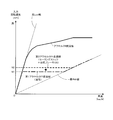
- FIG. 3 is a diagram for explaining an accelerator-off shift line when automatic braking is executed during sailing stop.
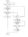
- FIG. 4 is a flowchart for explaining the control contents of the controller.
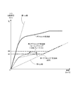
- FIG. 5 shows the behavior of the transmission when the accelerator OFF shift line is changed on the shift map.
- FIG. 6 is a time chart showing a state when automatic braking is executed during sailing stop.
- FIG. 1 shows a schematic configuration of a vehicle to which a control device according to an embodiment of the present invention is applied.
- the vehicle includes an engine 1 as a drive source.
- the output rotation of the engine 1 is transmitted to the drive wheels 6 via the torque converter 2, the forward / reverse switching mechanism 3, the transmission 4 and the final reduction mechanism 5.
- the engine 1 is an internal combustion engine that uses gasoline, light oil or the like as fuel, and the rotation speed and torque are controlled by a controller 100 described later. Further, during the sailing stop described later, the fuel supply to the engine 1 is stopped and the transmission 4 is controlled to the neutral state (power cut-off state), so that the engine 1 stops rotating.
- the engine 1 is provided with an alternator 11 that is driven by using a part of the driving force of the engine 1.
- the electric power generated by the alternator 11 is distributed to a brake system 8, a power steering system 9, an electric oil pump 72, a battery 12, and the like which will be described later.
- the power stored in the battery 12 is distributed to the brake system 8, the power steering system 9, the electric oil pump 72, etc. instead of the power generated by the alternator 11.
- the torque converter 2 is a torque converter having a lockup clutch 21.
- the lock-up clutch 21 is controlled to be engaged and released by a controller 100 described later based on the vehicle speed.
- the torque converter 2 amplifies and outputs the torque input from the engine 1.
- the lockup clutch 21 is engaged, the input shaft and the output shaft of the torque converter 2 are directly connected, and transmission loss due to slippage of the torque converter 2 is suppressed.
- the forward / reverse switching mechanism 3 includes a double pinion planetary gear mechanism 31, a forward clutch 32, and a reverse brake 33.
- the forward / reverse switching mechanism 3 realizes a forward state in which rotation is transmitted while maintaining the rotational direction, and when the forward clutch 32 is released and the reverse brake 33 is engaged, the rotational direction is changed. A reverse state that reverses and transmits the rotation is realized. Further, when the forward clutch 32 and the reverse brake 33 are released, the neutral state of the transmission 4 is realized, and the power cut-off state in which the engine 1 is disconnected from the power train is realized.
- the transmission 4 is a continuously variable transmission including a primary pulley 41, a secondary pulley 42, and a belt 43 that is stretched between the primary pulley 41 and the secondary pulley 42.
- the transmission ratio of the transmission 4 is controlled by a controller 100 described later.
- the primary pulley 41 includes a fixed pulley 41a and a movable pulley 41b that is disposed to face the fixed pulley 41a and has an oil chamber 41c on the back surface.
- the secondary pulley 42 includes a fixed pulley 42a and a movable pulley 42b that is disposed to face the fixed pulley 42a and has an oil chamber 42c on the back surface.
- the groove widths of the primary pulley 41 and the secondary pulley 42 are changed by changing the hydraulic pressure supplied to the oil chambers 41c and 42c and displacing the movable pulleys 41b and 42b.
- the hydraulic pressure supplied to the oil chambers 41 c and 42 c is supplied from the hydraulic circuit 7.
- the hydraulic circuit 7 adjusts the hydraulic pressure generated by at least one of the mechanical oil pump 71 and the electric oil pump 72 to the line pressure by the regulator valve 73. Further, the line pressure is adjusted to the primary pressure and the secondary pressure by the first pressure regulating valve 74 and the second pressure regulating valve 75. The primary pressure and the secondary pressure are respectively supplied to the oil chamber 41c of the primary pulley 41 and the oil chamber 42c of the secondary pulley 42, whereby the transmission 4 is shifted or the gear ratio is maintained.
- the mechanical oil pump 71 is driven using a part of the driving force of the engine 1, and when the engine 1 stops, the mechanical oil pump 71 also stops. Therefore, when the engine 1 is stopped, the hydraulic pressure required for the transmission 4 and the forward / reverse switching mechanism 3 is generated by the electric oil pump 72 driven by the electric power supplied from the battery 12.
- the electric power required by the electric oil pump 72 increases as the required hydraulic pressure increases, since the rotational speed of the electric oil pump 72 needs to be increased as the required hydraulic pressure increases.
- the gear ratio of the transmission 4 is controlled so that the target input rotation speed of the transmission 4 is set with reference to the shift map shown in FIG. 2 based on the vehicle speed and the accelerator pedal depression amount, and this is achieved.
- FIG. 2 for easy understanding, a shift line when the accelerator pedal is fully depressed (accelerator ON shift line) and a shift line when the accelerator pedal is not depressed (accelerator OFF shift line). Only shows.
- the actual shift map a plurality of shift lines when the accelerator pedal is partially depressed are set between the accelerator ON shift line and the accelerator OFF shift line.
- the final reduction mechanism 5 includes a plurality of gear trains 51 and a differential gear mechanism 52, and transmits the output rotation of the transmission 4 to the drive wheels 6.
- the vehicle is provided with a brake system 8 for braking the driving wheel 6 and a driven wheel (not shown).
- the brake system 8 includes a hydraulic brake 81 attached to each wheel, a brake sensor 82 that detects depression of a brake pedal by a driver, and a hydraulic pressure adjustment unit 83 that adjusts the brake hydraulic pressure of the hydraulic brake 81.
- the brake actuator 84 in the hydraulic pressure adjustment unit 83 is operated by the electric power from the alternator 11 or the battery 12.
- the brake actuator 84 displaces the piston of the master cylinder to adjust the brake fluid pressure to a fluid pressure corresponding to the amount of depression of the brake pedal.
- the brake system 8 also operates when executing automatic braking as will be described later.
- the power steering system 9 assists the driver's steering by a motor 91 driven by electric power supplied from the alternator 11 or the battery 12.
- the controller 100 includes a plurality of control units (an engine control unit, a transmission control unit, a body control module, etc.) that are communicably connected to each other via a CAN.
- Each control unit includes a microprocessor, a memory, an input / output interface, and the like.
- the controller 100 determines the driving state of the vehicle based on inputs from various sensors that detect the driving state of the vehicle, and the engine 1, the lockup clutch 21, the forward / reverse switching mechanism 3, the transmission 4, the brake system 8, and the power steering.
- the system 9 and the electric oil pump 72 are controlled in an integrated manner.
- the various sensors include a vehicle speed sensor 101, an accelerator opening sensor 102, a brake sensor 82, an engine rotation speed sensor 103, a transmission input rotation speed sensor 104, a range selection switch 105, and the like.
- the controller 100 is connected to a camera 106 that captures an image in front of the vehicle in the traveling direction.
- the controller 100 detects an object (a vehicle, a person, an obstacle, etc.) in front of the vehicle by analyzing an image captured by the camera 106.
- the controller 100 issues a warning consisting of sound, a message, etc. to the driver.
- the hydraulic brake 81 is automatically operated (automatic brake).
- the method for detecting an object in front of the vehicle is not limited to the method using the camera 106, and may be a detection method using an infrared device or millimeter wave radar instead of the camera 106 or in addition to the camera 106.
- controller 100 executes sailing stop control for completely stopping the rotation of the engine 1 by stopping the engine 1 and setting the transmission 4 to the neutral state in the coast state where the accelerator is coasting with the accelerator OFF. While the sailing is stopped, the engine 1 is not rotated and the engine brake does not act on the drive wheels 6, so that the fuel efficiency of the vehicle can be improved.
- the controller 100 determines that the sailing stop start condition is satisfied when the forward range is selected, the vehicle speed is equal to or higher than the set vehicle speed (medium to high vehicle speed), and the accelerator pedal and the brake pedal are not depressed. Then, the fuel supply to the engine 1 is stopped and the forward clutch 32 and the reverse brake 33 of the forward / reverse switching mechanism 3 are released to bring the transmission 4 into the neutral state.
- the engine 1 stops and the alternator 11 stops power generation, so that power is distributed from the battery 12 to the brake system 8, the power steering system 9, the electric oil pump 72, etc. instead of the alternator 11. .
- X / n1 is allocated to the brake system 8 at the maximum and X / n1 is allocated to the power steering system 9 at the maximum. This is done by allocating n2 and allocating X ⁇ (X / n1 + X / n2) at the maximum to the remaining parts.
- n1 and n2 are changed to values smaller than when automatic brake is not executed.
- the accelerator OFF shift line is changed to the high rotation side (hereinafter, the accelerator OFF shift line before the change is referred to as “first accelerator OFF shift line”).
- the changed accelerator OFF shift line is referred to as a “second accelerator OFF shift line”).
- Changing the accelerator-off shift line to the high rotation side means changing the target input rotation speed for each vehicle speed to a higher value in the vehicle speed range in which the shift line is used. As described above, the shift line is shifted upward (to the high rotation side).
- the target input rotational speed of the transmission 4 is changed stepwise from N1 to N2, and thereby the target of the transmission 4 is changed.
- the gear ratio is changed stepwise to Low, and the amount of downshift at the beginning of the shift is increased.
- part of the downshift is executed ahead of time before sudden deceleration due to automatic braking, and the amount of downshift during the subsequent sudden deceleration is reduced to lower the shift speed, thereby requiring the transmission 4 during the shift. To suppress the maximum power.
- FIG. 4 is a flowchart for explaining the control contents of the controller 100 for realizing this.
- step S1 the controller 100 determines whether sailing is stopped. Whether or not the sailing stop is in progress, a specific value (for example, 1) is set in a predetermined flag at the start of the sailing stop, and another specific value (for example, 0) is set when the sailing stop is released. This can be determined by referring to the value of the flag. If sailing is stopped, the process proceeds to step S2.
- a specific value for example, 1
- another specific value for example, 0
- step S2 the controller 100 selects the first accelerator OFF shift line (see FIG. 3) as the shift line when the accelerator is OFF. Thereby, the transmission 4 is shifted so that the operating point of the transmission 4 determined by the vehicle speed and the input rotational speed moves along the first accelerator OFF shift line.
- step S3 the controller 100 determines whether a sailing stop cancellation condition is satisfied.
- the sailing stop release condition is satisfied, for example, when an accelerator pedal or a brake pedal is depressed during sailing stop.
- step S4 the controller 100 cancels the sailing stop. That is, the engine 1 is started and the forward clutch 32 is engaged.
- step S3 if the sailing stop cancellation condition is not satisfied in step S3, the process proceeds to step S5.
- step S5 the controller 100 determines whether execution of automatic braking is detected. Whether or not the automatic brake is being executed is set such that a specific value (for example, 1) is set in a predetermined flag when the automatic brake is executed, and another specific value (for example, 0) is set when the automatic brake is released. This can be determined by referring to the value of the flag.
- a specific value for example, 1
- another specific value for example, 0
- step S6 If the execution of automatic braking is detected, the process proceeds to step S6; otherwise, the process returns to step S2.
- step S6 the controller 100 prohibits the restart of the engine 1.
- step S7 the controller 100 selects the second accelerator-off shift line (see FIG. 3) that is set higher than the first accelerator-off shift line as the shift line when the accelerator is off.
- the target input rotational speed of the transmission 4 is changed from N1 to N2, and the operating point of the transmission 4 on or near the first accelerator OFF shift line is an automatic brake as shown by the solid line in FIG.
- the shift of the transmission 4 is performed prior to the sudden deceleration of the vehicle by automatic braking from the position X when the execution of the vehicle is detected toward the second accelerator OFF shift line.
- the downshift of the transmission 4 is performed at a high speed with the sudden deceleration of the vehicle, and the operating point of the transmission 4 moves toward the origin O.
- the two-dot chain line is the behavior of the operating point of the transmission 4 when the shift line is not changed.
- step S7 is continued until it is determined in step S8 that the automatic brake is released.
- step S8 If it is determined in step S8 that the automatic brake has been released, the process proceeds to step S9, and the controller 100 restarts the engine 1 and engages the forward clutch 32 (sailing stop release).
- FIG. 6 shows a state in which automatic braking is executed while sailing is stopped.
- a solid line indicates the present embodiment (with a change in the shift line), and a broken line indicates a comparative example (without a change in the shift line). The effect by performing the said control is demonstrated referring this.
- the state before execution of automatic braking is sailing stopped, and in this state, the vehicle speed gradually decreases, and the downshift of the transmission 4 is gradually performed accordingly.
- the shift line used at this time is the first accelerator OFF shift line (FIG. 2).
- the shift line is changed from the first accelerator OFF shift line to the second accelerator OFF shift line.
- the downshift of the transmission 4 is partly advanced ahead of the sudden deceleration of the vehicle.
- the sudden deceleration of the vehicle due to the automatic brake has a slight delay time from when the brake actuator 84 starts to operate until the braking force is actually applied to the drive wheels 6, so from the timing when the execution of the automatic brake is detected. Occurs late.
- the downshift of the transmission 4 is performed at a high shift speed in accordance with the sudden deceleration of the vehicle, but the amount of downshift during the sudden deceleration is reduced by increasing the amount of downshift before the sudden deceleration. Since the transmission speed of the transmission 4 is suppressed, the maximum power (instantaneous maximum energy) required by the transmission 4 is suppressed.
- the transmission 4 can be sufficiently downshifted while the power consumption of the transmission 4 is kept below the maximum power. It is possible to prevent the necessary driving force from being obtained at the time of restart or reacceleration after releasing the automatic brake.
- the drive source is an engine in this embodiment, the drive source may be a combination of an engine and a motor, or a motor.
- the drive source engine 1 and / or motor
- the drive source is restarted after the automatic brake is released.
- it is possible to prevent the problem of insufficient downshift due to power shortage due to power consumption for restarting the drive source.
Abstract
Description
Claims (3)
- 駆動源と、無段変速機と、を有する車両の制御装置であって、
前記車両の走行中に前記駆動源の停止を行うセーリングストップ中に自動ブレーキの実行を検知すると、前記無段変速機の変速線を高回転側に変更する制御部を有する、
車両の制御装置。 - 請求項1に記載の車両の制御装置において、
前記制御部は、前記自動ブレーキの解除後に前記駆動源を再始動する、
車両の制御装置。 - 駆動源と、無段変速機と、を有する車両の制御方法であって、
前記車両の走行中に前記駆動源の停止を行うセーリングストップ中に自動ブレーキの実行を検知すると、前記無段変速機の変速線を高回転側に変更する、
車両の制御方法。
Priority Applications (4)
| Application Number | Priority Date | Filing Date | Title |
|---|---|---|---|
| CN201780026115.XA CN109073072B (zh) | 2016-05-25 | 2017-04-12 | 具备无级变速器的车辆的控制装置及控制方法 |
| KR1020187030878A KR102047617B1 (ko) | 2016-05-25 | 2017-04-12 | 무단 변속기를 구비한 차량의 제어 장치 및 제어 방법 |
| US16/303,905 US10962111B2 (en) | 2016-05-25 | 2017-04-12 | Control device and control method for vehicle including continuously variable transmission |
| JP2018519138A JP6697548B2 (ja) | 2016-05-25 | 2017-04-12 | 無段変速機を備えた車両の制御装置及び制御方法 |
Applications Claiming Priority (2)
| Application Number | Priority Date | Filing Date | Title |
|---|---|---|---|
| JP2016104277 | 2016-05-25 | ||
| JP2016-104277 | 2016-05-25 |
Publications (1)
| Publication Number | Publication Date |
|---|---|
| WO2017203874A1 true WO2017203874A1 (ja) | 2017-11-30 |
Family
ID=60411969
Family Applications (1)
| Application Number | Title | Priority Date | Filing Date |
|---|---|---|---|
| PCT/JP2017/014942 WO2017203874A1 (ja) | 2016-05-25 | 2017-04-12 | 無段変速機を備えた車両の制御装置及び制御方法 |
Country Status (5)
| Country | Link |
|---|---|
| US (1) | US10962111B2 (ja) |
| JP (1) | JP6697548B2 (ja) |
| KR (1) | KR102047617B1 (ja) |
| CN (1) | CN109073072B (ja) |
| WO (1) | WO2017203874A1 (ja) |
Cited By (1)
| Publication number | Priority date | Publication date | Assignee | Title |
|---|---|---|---|---|
| JP2019218000A (ja) * | 2018-06-22 | 2019-12-26 | 本田技研工業株式会社 | 衝突軽減制御装置 |
Families Citing this family (3)
| Publication number | Priority date | Publication date | Assignee | Title |
|---|---|---|---|---|
| WO2020261918A1 (ja) * | 2019-06-24 | 2020-12-30 | ジヤトコ株式会社 | 車両の制御装置及び車両の制御方法 |
| CN111412097B (zh) * | 2020-03-04 | 2022-08-02 | 吉利汽车研究院(宁波)有限公司 | 一种车辆辅助启动系统及方法 |
| JP7241124B2 (ja) * | 2021-04-21 | 2023-03-16 | 本田技研工業株式会社 | 車両用無段変速機の制御装置及び制御方法 |
Citations (4)
| Publication number | Priority date | Publication date | Assignee | Title |
|---|---|---|---|---|
| JPS5973651A (ja) * | 1982-10-21 | 1984-04-25 | Fuji Heavy Ind Ltd | 無段変速機の制御装置 |
| JP2009138923A (ja) * | 2007-11-16 | 2009-06-25 | Aisin Aw Co Ltd | 車両制御装置、車両制御方法及びコンピュータプログラム |
| JP2009216167A (ja) * | 2008-03-10 | 2009-09-24 | Nissan Motor Co Ltd | 車両用無段変速機の変速制御装置 |
| JP2016016753A (ja) * | 2014-07-08 | 2016-02-01 | ジヤトコ株式会社 | 駆動機構 |
Family Cites Families (10)
| Publication number | Priority date | Publication date | Assignee | Title |
|---|---|---|---|---|
| JP2003259504A (ja) * | 2002-03-06 | 2003-09-12 | Nissan Motor Co Ltd | 制動制御装置 |
| WO2004024486A1 (ja) * | 2002-09-13 | 2004-03-25 | Honda Giken Kogyo Kabushiki Kaisha | ハイブリッド車両 |
| JP4193600B2 (ja) | 2003-06-11 | 2008-12-10 | 日産自動車株式会社 | 自動ブレーキ制御装置 |
| JP2006094589A (ja) * | 2004-09-21 | 2006-04-06 | Toyota Motor Corp | 車両の減速度制御装置 |
| JP2006137392A (ja) * | 2004-11-15 | 2006-06-01 | Toyota Motor Corp | 車両の減速制御装置 |
| JP5526005B2 (ja) * | 2010-11-25 | 2014-06-18 | ジヤトコ株式会社 | コーストストップ車両及びコーストストップ車両の制御方法 |
| JP2013213557A (ja) | 2012-04-03 | 2013-10-17 | Toyota Motor Corp | 車両の制御装置 |
| KR101678322B1 (ko) * | 2012-07-31 | 2016-11-21 | 쟈트코 가부시키가이샤 | 차량용 자동 변속기 |
| WO2016021431A1 (ja) * | 2014-08-07 | 2016-02-11 | 日立オートモティブシステムズ株式会社 | 車両の制御装置 |
| US10556591B2 (en) * | 2016-02-29 | 2020-02-11 | Hitachi Automotive Systems, Ltd. | Vehicle control device |
-
2017
- 2017-04-12 CN CN201780026115.XA patent/CN109073072B/zh active Active
- 2017-04-12 JP JP2018519138A patent/JP6697548B2/ja active Active
- 2017-04-12 KR KR1020187030878A patent/KR102047617B1/ko active IP Right Grant
- 2017-04-12 US US16/303,905 patent/US10962111B2/en active Active
- 2017-04-12 WO PCT/JP2017/014942 patent/WO2017203874A1/ja active Application Filing
Patent Citations (4)
| Publication number | Priority date | Publication date | Assignee | Title |
|---|---|---|---|---|
| JPS5973651A (ja) * | 1982-10-21 | 1984-04-25 | Fuji Heavy Ind Ltd | 無段変速機の制御装置 |
| JP2009138923A (ja) * | 2007-11-16 | 2009-06-25 | Aisin Aw Co Ltd | 車両制御装置、車両制御方法及びコンピュータプログラム |
| JP2009216167A (ja) * | 2008-03-10 | 2009-09-24 | Nissan Motor Co Ltd | 車両用無段変速機の変速制御装置 |
| JP2016016753A (ja) * | 2014-07-08 | 2016-02-01 | ジヤトコ株式会社 | 駆動機構 |
Cited By (1)
| Publication number | Priority date | Publication date | Assignee | Title |
|---|---|---|---|---|
| JP2019218000A (ja) * | 2018-06-22 | 2019-12-26 | 本田技研工業株式会社 | 衝突軽減制御装置 |
Also Published As
| Publication number | Publication date |
|---|---|
| KR20180122727A (ko) | 2018-11-13 |
| JP6697548B2 (ja) | 2020-05-20 |
| CN109073072B (zh) | 2020-05-22 |
| KR102047617B1 (ko) | 2019-11-21 |
| US20200318736A1 (en) | 2020-10-08 |
| JPWO2017203874A1 (ja) | 2019-03-28 |
| US10962111B2 (en) | 2021-03-30 |
| CN109073072A (zh) | 2018-12-21 |
Similar Documents
| Publication | Publication Date | Title |
|---|---|---|
| US9470156B2 (en) | Vehicle engine automatic control device and vehicle engine automatic control method | |
| JP5728422B2 (ja) | ベルト式無段変速機の変速制御装置 | |
| EP2789834B1 (en) | Automatic vehicle-engine control device | |
| US9562480B2 (en) | Automatic engine-stop control device for vehicle | |
| EP3179125B1 (en) | Vehicle control device, and vehicle control method | |
| JP6241424B2 (ja) | 車両制御装置 | |
| JP2007331533A (ja) | 車両用制御装置 | |
| WO2017203874A1 (ja) | 無段変速機を備えた車両の制御装置及び制御方法 | |
| WO2013051128A1 (ja) | エンジン始動システム | |
| JP2014134275A (ja) | 車両の制御装置 | |
| JP5617646B2 (ja) | 車両制御装置 | |
| WO2013179753A1 (ja) | エンジン制御装置 | |
| US10501083B2 (en) | Vehicle control device and vehicle control method | |
| JP6446278B2 (ja) | コーストストップ制御装置 | |
| JP2017067205A (ja) | 車両用制御装置 | |
| JP2013217271A (ja) | 車両の制御装置 | |
| WO2019069344A1 (ja) | 車両の制御方法及び車両の制御装置 | |
| JP5928288B2 (ja) | クラッチの制御装置 | |
| JP2021032303A (ja) | 車両の制御装置及び車両の制御方法 | |
| WO2019069444A1 (ja) | 内燃機関の制御方法及び内燃機関の制御装置 | |
| JP2018115703A (ja) | 車両及び車両の制御方法 | |
| JP2018114831A (ja) | 車両及び車両の制御方法 |
Legal Events
| Date | Code | Title | Description |
|---|---|---|---|
| ENP | Entry into the national phase |
Ref document number: 2018519138 Country of ref document: JP Kind code of ref document: A |
|
| ENP | Entry into the national phase |
Ref document number: 20187030878 Country of ref document: KR Kind code of ref document: A |
|
| NENP | Non-entry into the national phase |
Ref country code: DE |
|
| 121 | Ep: the epo has been informed by wipo that ep was designated in this application |
Ref document number: 17802473 Country of ref document: EP Kind code of ref document: A1 |
|
| 122 | Ep: pct application non-entry in european phase |
Ref document number: 17802473 Country of ref document: EP Kind code of ref document: A1 |