WO2013077193A1 - 加工装置および加工方法 - Google Patents
加工装置および加工方法 Download PDFInfo
- Publication number
- WO2013077193A1 WO2013077193A1 PCT/JP2012/078981 JP2012078981W WO2013077193A1 WO 2013077193 A1 WO2013077193 A1 WO 2013077193A1 JP 2012078981 W JP2012078981 W JP 2012078981W WO 2013077193 A1 WO2013077193 A1 WO 2013077193A1
- Authority
- WO
- WIPO (PCT)
- Prior art keywords
- lifter
- long plate
- lift
- processing apparatus
- sheet material
- Prior art date
Links
Images


Classifications
-
- B—PERFORMING OPERATIONS; TRANSPORTING
- B21—MECHANICAL METAL-WORKING WITHOUT ESSENTIALLY REMOVING MATERIAL; PUNCHING METAL
- B21D—WORKING OR PROCESSING OF SHEET METAL OR METAL TUBES, RODS OR PROFILES WITHOUT ESSENTIALLY REMOVING MATERIAL; PUNCHING METAL
- B21D45/00—Ejecting or stripping-off devices arranged in machines or tools dealt with in this subclass
- B21D45/02—Ejecting devices
- B21D45/04—Ejecting devices interrelated with motion of tool
-
- B—PERFORMING OPERATIONS; TRANSPORTING
- B21—MECHANICAL METAL-WORKING WITHOUT ESSENTIALLY REMOVING MATERIAL; PUNCHING METAL
- B21D—WORKING OR PROCESSING OF SHEET METAL OR METAL TUBES, RODS OR PROFILES WITHOUT ESSENTIALLY REMOVING MATERIAL; PUNCHING METAL
- B21D22/00—Shaping without cutting, by stamping, spinning, or deep-drawing
- B21D22/02—Stamping using rigid devices or tools
- B21D22/06—Stamping using rigid devices or tools having relatively-movable die parts
-
- B—PERFORMING OPERATIONS; TRANSPORTING
- B21—MECHANICAL METAL-WORKING WITHOUT ESSENTIALLY REMOVING MATERIAL; PUNCHING METAL
- B21D—WORKING OR PROCESSING OF SHEET METAL OR METAL TUBES, RODS OR PROFILES WITHOUT ESSENTIALLY REMOVING MATERIAL; PUNCHING METAL
- B21D28/00—Shaping by press-cutting; Perforating
- B21D28/02—Punching blanks or articles with or without obtaining scrap; Notching
- B21D28/06—Making more than one part out of the same blank; Scrapless working
-
- B—PERFORMING OPERATIONS; TRANSPORTING
- B21—MECHANICAL METAL-WORKING WITHOUT ESSENTIALLY REMOVING MATERIAL; PUNCHING METAL
- B21D—WORKING OR PROCESSING OF SHEET METAL OR METAL TUBES, RODS OR PROFILES WITHOUT ESSENTIALLY REMOVING MATERIAL; PUNCHING METAL
- B21D43/00—Feeding, positioning or storing devices combined with, or arranged in, or specially adapted for use in connection with, apparatus for working or processing sheet metal, metal tubes or metal profiles; Associations therewith of cutting devices
- B21D43/003—Positioning devices
-
- H—ELECTRICITY
- H02—GENERATION; CONVERSION OR DISTRIBUTION OF ELECTRIC POWER
- H02K—DYNAMO-ELECTRIC MACHINES
- H02K15/00—Methods or apparatus specially adapted for manufacturing, assembling, maintaining or repairing of dynamo-electric machines
- H02K15/02—Methods or apparatus specially adapted for manufacturing, assembling, maintaining or repairing of dynamo-electric machines of stator or rotor bodies
- H02K15/024—Methods or apparatus specially adapted for manufacturing, assembling, maintaining or repairing of dynamo-electric machines of stator or rotor bodies with slots
-
- B—PERFORMING OPERATIONS; TRANSPORTING
- B21—MECHANICAL METAL-WORKING WITHOUT ESSENTIALLY REMOVING MATERIAL; PUNCHING METAL
- B21D—WORKING OR PROCESSING OF SHEET METAL OR METAL TUBES, RODS OR PROFILES WITHOUT ESSENTIALLY REMOVING MATERIAL; PUNCHING METAL
- B21D35/00—Combined processes according to or processes combined with methods covered by groups B21D1/00 - B21D31/00
- B21D35/001—Shaping combined with punching, e.g. stamping and perforating
-
- B—PERFORMING OPERATIONS; TRANSPORTING
- B21—MECHANICAL METAL-WORKING WITHOUT ESSENTIALLY REMOVING MATERIAL; PUNCHING METAL
- B21D—WORKING OR PROCESSING OF SHEET METAL OR METAL TUBES, RODS OR PROFILES WITHOUT ESSENTIALLY REMOVING MATERIAL; PUNCHING METAL
- B21D45/00—Ejecting or stripping-off devices arranged in machines or tools dealt with in this subclass
- B21D45/003—Ejecting or stripping-off devices arranged in machines or tools dealt with in this subclass in punching machines or punching tools
-
- H—ELECTRICITY
- H01—ELECTRIC ELEMENTS
- H01F—MAGNETS; INDUCTANCES; TRANSFORMERS; SELECTION OF MATERIALS FOR THEIR MAGNETIC PROPERTIES
- H01F41/00—Apparatus or processes specially adapted for manufacturing or assembling magnets, inductances or transformers; Apparatus or processes specially adapted for manufacturing materials characterised by their magnetic properties
- H01F41/02—Apparatus or processes specially adapted for manufacturing or assembling magnets, inductances or transformers; Apparatus or processes specially adapted for manufacturing materials characterised by their magnetic properties for manufacturing cores, coils, or magnets
Definitions
- the present invention relates to a processing apparatus and a processing method for performing a process including a punching process on a sheet material using a mold having an upper mold and a lower mold.
- the rigidity of the sheet material decreases as the wide sheet material is sequentially punched. Therefore, the sheet material is easily bent as it goes to the downstream stage, and there is a possibility that the deformation of the sheet material due to being caught on the processing apparatus and the damage of the processing apparatus accompanying the deformation.
- the present invention provides a processing apparatus and a processing method that are free from damage due to catching of a sheet material.
- the processing apparatus is: A processing device that sends a long plate-like body from the upstream side to the downstream side and performs press processing including punching processing on the long plate-like body sequentially, A plurality of stages provided along the feed direction of the long plate-shaped body, each having a mold for pressing the long plate-shaped body, A lift-up part that separates the long plate-like body from the mold by a predetermined separation length, and a plurality of lifters provided along the feeding direction of the long plate-like body, For the plurality of lifters, the separation length of the lifter disposed on the downstream side by the lift-up portion is set to be greater than the separation length of the lifter disposed on the upstream side by the lift-up portion. Yes.
- the number of the lift-up portions of the lifter disposed on the downstream side may be set larger than the number of the lift-up portions of the lifter disposed on the upstream side.
- the lift-up part of the lifter is arranged side by side in the width direction of the long plate-shaped body, A width of the lift-up portion of the lifter disposed on the downstream side may be wider than a width of the lift-up portion of the lifter disposed on the upstream side.
- Said processing apparatus WHEREIN Two or more said lift up parts may be provided along the width direction of the said elongate plate-shaped object.
- the processing method according to the present invention includes: A processing method in which a long plate-shaped body is sent from the upstream side to the downstream side, and the long plate-shaped body is sequentially subjected to press processing including punching processing, The long plate-like body sent to each stage to be processed is lifted higher toward the downstream side by a lifter provided on each stage.
- the processing apparatus and the processing method of the present invention there is no risk of damage to the processing apparatus due to the long plate-like body being caught on the processing apparatus when the long plate-like body is conveyed by the lifter.
- FIG. 3 is a plan view of a lower mold corresponding to FIG. 2. It is a cross-sectional enlarged view of the lifter periphery of a processing apparatus.
- FIG. 1 is a plan view showing a processing state of a long plate-like body to which the processing apparatus according to the embodiment is applied.
- FIG. 2 is a cross-sectional view of the long plate-like body and the processing apparatus during processing.
- FIG. 3 is a plan view of a state corresponding to FIG.
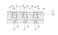
- FIG. 4 is an enlarged cross-sectional view around the lifter of the processing apparatus.
- the processing apparatus 10 is a laminated iron core manufacturing apparatus that can be suitably used as a motor core or stator.
- This laminated iron core is obtained by punching out a desired shape from a long electromagnetic steel plate (long plate-like body).
- a processing apparatus 10 includes a plurality of stages (a) each having a common lower mold (mold) 11 and an upper mold (not shown) disposed thereon. Has (l).
- the plurality of stages (a) to (l) are provided along the feeding direction of the sheet material 12 to be processed (direction from left to right in FIGS. 1 to 3).
- reference numerals (a) to (l) indicate regions placed on the stages (a) to (l), respectively.
- reference numerals (a) to (l) indicate regions of stages (a) to (l), respectively.
- the sheet material 12 made of a long electromagnetic steel sheet is sequentially conveyed to each stage (a) to (l). First, unnecessary portions are punched into a predetermined shape stepwise in stages (a) to (e), and the rotor core piece 13 is separated from the sheet material 12 in stage (f). Thereby, the rotor core piece 13 is obtained.
- the sheet material 12 from which the rotor core piece 13 is separated is continuously conveyed to the downstream side, and unnecessary portions are punched into a predetermined shape by the stages (h) to (k), and the stage (l) located at the most downstream side.
- the stator core piece 14 is separated from the sheet material 12.
- the lower mold 11 has a die (not shown) and a die plate 16 (see FIG. 4).
- a plurality of lifters 17 to 21 shown in FIGS. 1 to 3 are provided on the die plate 16.
- Lifters 17 to 21 are provided on the front side of the stage (a) and at the boundary positions of the stages (a) to (l), respectively. Further, a lifter 20 is provided at the center position in the feed direction in the stage (j), and a lifter 21 is provided at the center position in the feed direction in the stage (l).
- the lifter 17 has a lifter pin (lift-up portion) 26 that moves up and down in a punch hole 25 provided in the die plate 16, and a spring 27.
- the lifter pin 26 is a member that contacts the sheet material 12 and applies a force to lift the sheet material 12 from the die plate 16.
- the spring 27 applies an upward force to the lifter pin 26 so that the upper surface of the lifter pin 26 is lifted to a predetermined height protruding from the upper surface of the die plate 16. Since the lifters 18 to 21 have the same configuration as the lifter 17, detailed description thereof is omitted.
- the lifter pin 26 is pushed down by the stripper as the upper die is lowered. When a predetermined portion is punched from the sheet material 12 by the upper mold 11 and the lower mold 11, the lifter pin 26 does not protrude from the upper surface of the die plate 16.
- the lifter pin 26 is raised by the elastic force of the spring 27 as the upper die is raised, and protrudes from the upper surface of the die plate 16.
- the sheet material 12 is lifted by the lifter pins 26 and separated upward from the die plate 16. In this state, the sheet material 12 is conveyed downstream by a conveyance device (not shown).
- a slope 28 that is inclined downward is formed on the top of the lifter pin 26, and a horizontal plane 29 is formed on the downstream side of the slope 28.
- a horizontal plane 29 is formed on the downstream side of the slope 28.
- the top of the lifter pin 26 may be formed in an arc shape in cross section.
- each of the lifters 17 to 21 is provided at a position on the near side of the stage (a) and a boundary position between the stages (a) to (l).
- the distance L from the lower mold 11 by the lifter pin 26 of the lifter 17 is 6 mm
- the distance L from the lower mold 11 by the lifter pin 26 of the lifter 18 is 7 mm
- by the lifter pin 26 of the lifter 19 is 8 mm
- the separation length L from the lower mold 11 by the lifter pin 26 of the lifter 20 is 10 mm
- the separation length L from the lower mold 11 by the lifter pin 26 of the lifter 21 is 13 mm. Is set.
- the separation length L of the sheet material 12 from the die plate 16 by the lifter pin 26 of the downstream lifter is the separation length L of the upstream lifter lifter pin 26. Same or larger than
- the lifter pins 26 of the lifter 17 at the front side of the stage (a) and the boundary positions of the stages (a) to (d) are provided one by one at the center position in the width direction of the lower mold 11 (die plate 16). It has been.
- the lifters 17 to 21 provided on the downstream side of the lifter 17 are provided in the width direction of the sheet material 12 (direction perpendicular to the feeding direction). ) Two lifter pins 26 are provided.
- the sheet material 12 is sequentially passed through the stages (a) to (l), and the sheet material 12 is punched at each stage (a) to (l). As a result, the rigidity of the sheet material 12 gradually decreases every time it is punched.
- the portion that becomes the shaft hole of the rotor core piece 13 is punched from the sheet material 12, and the rotor core piece 13 is punched after the stage (f). For this reason, the rigidity of the sheet material 12 gradually decreases. Therefore, it becomes easy to bend when the sheet material 12 is lifted. Then, the width direction edge part of the sheet
- the separation length of the lifters 17 to 21 by the lifter pins 26 increases toward the downstream side. Is set to Thereby, even if the sheet material 12 bends downward on the downstream side, the sheet material 12 is lifted higher toward the downstream side by the lifters 17 to 21 provided in each stage. Thereby, it can suppress that the sheet
- the number of lifter pins 26 of the lifter arranged on the downstream side is made larger than the number of lifter pins 26 of the lifter arranged on the upstream side.
- the width of the lifter pins 26 of the lifters arranged on the downstream side is as follows.
- the width of the lifter pin 26 of the lifter disposed on the upstream side is set wider than the width.
- the lifter can support the sheet material 12 at a plurality of support points. Thereby, the sheet
- the present invention is not limited to the above-described embodiment, and the configuration thereof can be changed without changing the gist of the present invention.
- the height, number, width, and interval of the lifter pins are not limited to the above numerical values, and can be changed according to the shape and size of the sheet material to be processed.
- both the rotor core piece and the stator core piece are punched from the sheet material, but the present invention can be applied to the case where only one of them is formed. Furthermore, you may provide a 1 or 2 or more lifter pin in the downstream stage between the lifter pins arrange
- the lifters 17 to 21 that are physically lifted in contact with the sheet material 12 have been described.
- air that lifts the sheet material from the lower mold 11 by blowing gas or the like toward the sheet material. You may apply this invention to the processing apparatus provided with the lifter (lift-up part).
- the processing apparatus 10 that performs punching at all stages has been described as an example, but the present invention is not limited to this.
- the present invention may be applied to a processing apparatus capable of performing pressing such as punching or bending.
- the laminated iron core manufacturing apparatus has been described as an example of the processing apparatus 10, but the present invention is not limited to this.
- the present invention can be applied to a punching device for a thin metal plate such as a punching device for a lead frame used for electronic parts or the like, or a punching device for other precision parts.
- a processing apparatus and a processing method that can suppress the long plate-like body from being caught on the processing apparatus when the long plate-like body is transported by the lifter and that does not cause damage. it can.
Landscapes
- Engineering & Computer Science (AREA)
- Mechanical Engineering (AREA)
- Manufacturing & Machinery (AREA)
- Power Engineering (AREA)
- Press Drives And Press Lines (AREA)
- Manufacture Of Motors, Generators (AREA)
- Manufacturing Cores, Coils, And Magnets (AREA)
Abstract
長尺板状体(12)を上流側から下流側に送って、長尺板状体(12)に順次打ち抜き加工を含むプレス加工を行う加工装置(10)であって、それぞれ長尺板状体(12)にプレス加工を行う金型(11)を備え、長尺板状体(12)の送り方向に沿って設けられた複数のステージ(a)~(l)と、長尺板状体(12)を金型(11)から持ち上げるリフトアップ部を有し、長尺板状体(12)の送り方向に沿って設けられた複数のリフター(17,18,19,20,21)と、を備え、複数のリフター(17,18,19,20,21)について、下流側に配置されたリフター(17,18,19,20,21)のリフトアップ部(26)による離間長さLが、上流側に配置されたリフター(17,18,19,20,21)のリフトアップ部(26)による離間長さLよりも大きくなるように設定されている加工装置10が提供される。
Description
本発明は、上型と下型を有する金型を用いてシート材に打ち抜き加工を含む加工を施す加工装置および加工方法に関する。
シート材を順次上流から下流に搬送しながらシート材に加工を施す加工装置において、特許文献1に記載のように、各ステージに機械的なリフターやエアリフターを設けたものが提案されている。この特許文献1の加工装置においては、各ステージにリフターが設けられている。この加工装置において、自由状態のリフターの突出高さは同一で、進行方向に隣り合うリフターの間隔も同一であり、更に各ステージにおけるリフターの幅も同一である。
しかしながら、幅広のシート材に順次打ち抜き加工を施す程、シート材の剛性は低下していく。よって、下流側のステージに行くに従って、シート材は撓み易くなり、加工装置への引っ掛かりによるシート材の変形、それに伴う加工装置の損傷が発生する可能性がある。
そこで本発明は、シート材の引っ掛かりによる損傷の虞のない加工装置、および加工方法を提供する。
本発明に係る加工装置は、
長尺板状体を上流側から下流側に送って、長尺板状体に順次打ち抜き加工を含むプレス加工を行う加工装置であって、
それぞれ長尺板状体にプレス加工を行う金型を備え、長尺板状体の送り方向に沿って設けられた複数のステージと、
長尺板状体を前記金型から所定の離間長さだけ離間させるリフトアップ部を有し、長尺板状体の送り方向に沿って設けられた複数のリフターと、を備え、
複数の前記リフターについて、下流側に配置された前記リフターの前記リフトアップ部による離間長さが、上流側に配置された前記リフターの前記リフトアップ部による離間長さよりも大きくなるように設定されている。
長尺板状体を上流側から下流側に送って、長尺板状体に順次打ち抜き加工を含むプレス加工を行う加工装置であって、
それぞれ長尺板状体にプレス加工を行う金型を備え、長尺板状体の送り方向に沿って設けられた複数のステージと、
長尺板状体を前記金型から所定の離間長さだけ離間させるリフトアップ部を有し、長尺板状体の送り方向に沿って設けられた複数のリフターと、を備え、
複数の前記リフターについて、下流側に配置された前記リフターの前記リフトアップ部による離間長さが、上流側に配置された前記リフターの前記リフトアップ部による離間長さよりも大きくなるように設定されている。
上記の加工装置において、下流側に配置された前記リフターの前記リフトアップ部の個数が、上流側に配置された前記リフターの前記リフトアップ部の個数よりも大きく設定されていてもよい。
上記の加工装置において、前記リフターの前記リフトアップ部は、前記長尺板状体の幅方向に並んで配置され、
下流側に配置された前記リフターの前記リフトアップ部の幅は、上流側に配置された前記リフターの前記リフトアップ部の幅よりも広くされていてもよい。
上記の加工装置において、前記長尺板状体の幅方向に沿って2つ以上の前記リフトアップ部が設けられていてもよい。
上記の加工装置において、前記リフターの前記リフトアップ部は、前記長尺板状体の幅方向に並んで配置され、
下流側に配置された前記リフターの前記リフトアップ部の幅は、上流側に配置された前記リフターの前記リフトアップ部の幅よりも広くされていてもよい。
上記の加工装置において、前記長尺板状体の幅方向に沿って2つ以上の前記リフトアップ部が設けられていてもよい。
本発明に係る加工方法は、
長尺板状体を上流側から下流側に送って、前記長尺板状体に順次打ち抜き加工を含むプレス加工を行う加工方法であって、
加工を行う各ステージに送られる前記長尺板状体を、各前記ステージに設けられたリフターによって、下流側ほど高く持ち上げる。
長尺板状体を上流側から下流側に送って、前記長尺板状体に順次打ち抜き加工を含むプレス加工を行う加工方法であって、
加工を行う各ステージに送られる前記長尺板状体を、各前記ステージに設けられたリフターによって、下流側ほど高く持ち上げる。
本発明に係る加工装置および加工方法によれば、リフターによる長尺板状体の搬送時に、長尺板状体が加工装置へ引っ掛かることによる加工装置の損傷の虞がない。
図1から図4を参照しながら、本発明の実施形態に係る加工装置を説明する。
図1は、実施形態に係る加工装置を適用した長尺板状体の加工状態を示す平面図である。図2は、加工中の長尺板状体および加工装置の断面図である。図3は、図2に対応する状態の平面図である。図4は加工装置のリフター周辺の断面拡大図である。
図1は、実施形態に係る加工装置を適用した長尺板状体の加工状態を示す平面図である。図2は、加工中の長尺板状体および加工装置の断面図である。図3は、図2に対応する状態の平面図である。図4は加工装置のリフター周辺の断面拡大図である。
本実施形態に係る加工装置10は、モータのコアやステータとして好適に用いることができる積層鉄心の製造装置である。この積層鉄心は、長尺の電磁鋼板(長尺板状体)から所望の形状を打ち抜くことにより得られる。
図1から図4に示すように、本実施形態に係る加工装置10は、共通の下型(金型)11と、その上に配置される図示しない上型をそれぞれ有する複数のステージ(a)~(l)を有する。複数のステージ(a)~(l)は、加工対象であるシート材12の送り方向(図1から図3において左から右に向かう方向)に沿って設けられている。図1において、符号(a)~(l)はそれぞれ、ステージ(a)~(l)に載置される領域を示している。図2,3において符号(a)~(l)はそれぞれ、ステージ(a)~(l)の領域を示している。
加工装置10において、長尺の電磁鋼板からなるシート材12は順次各ステージ(a)~(l)に搬送される。まず、ステージ(a)~(e)で段階的に不要部分を所定の形状に打ち抜き、ステージ(f)で回転子鉄心片13をシート材12から切り離す。これにより、回転子鉄心片13が得られる。
さらに、回転子鉄心片13が切り離されたシート材12を続けて下流側に搬送し、ステージ(h)~(k)で不要部分を所定形状に打ち抜き、最下流に位置するステージ(l)で固定子鉄心片14をシート材12から切り離す。加工装置10を用いると、このようにして、回転子鉄心片13、及び固定子鉄心片14が製造される。
下型11は図示しないダイとダイプレート16(図4参照)とを有する。ダイプレート16には図1から図3に示すリフター17~21がそれぞれ複数設けられている。
ステージ(a)の手前側、ステージ(a)~(l)の境界位置に、それぞれリフター17~21が設けられている。更に、ステージ(j)内の送り方向の中央位置にリフター20が、ステージ(l)内の送り方向の中央位置にリフター21が設けられている。
図4に示したように、このリフター17は、ダイプレート16内に設けられた抜き孔25内を上下動するリフターピン(リフトアップ部)26と、スプリング27と、を有している。
リフターピン26は、シート材12と接触してシート材12をダイプレート16から持ち上げる力を作用させる部材である。スプリング27は、リフターピン26の上面がダイプレート16の上面から突出する所定高さまで持ち上げるように、リフターピン26に上向きの力を作用させている。なお、リフター18~21もリフター17と同様の構成を有するため、その詳細な説明は省略する。
リフターピン26は上型の下降に伴いストリッパーに押されて下降する。上型および下型11によってシート材12から所定部分を打ち抜く際には、リフターピン26はダイプレート16の上面から突出しない。
またリフターピン26は、上型の上昇に伴ってスプリング27の弾性力によって上昇し、ダイプレート16の上面から突出する。これにより、シート材12の各ステージ(a)~(l)による打ち抜き加工が完了した後には、シート材12はリフターピン26によって持ち上げられ、ダイプレート16から上方に離間される。この状態で、シート材12は図示しない搬送装置により下流側に搬送される。
リフターピン26の頂部には、上流側に下り傾斜となった斜面28が形成されており、斜面28の下流側には水平面29が形成されている。もっとも、斜面28、水平面29のいずれか一方又は双方を省略してもよい。また、リフターピン26の頂部について、断面円弧状に形成してもよい。
図3に示すように、各リフター17~21は、ステージ(a)の手前側位置、及び各ステージ(a)~(l)の境界位置にそれぞれ設けられている。本実施形態において、リフター17のリフターピン26による下型11からの離間長さLは6mm、リフター18のリフターピン26による下型11からの離間長さLは7mm、リフター19のリフターピン26による下型11からの離間長さLは8mm、リフター20のリフターピン26による下型11からの離間長さLは10mm、リフター21のリフターピン26による下型11からの離間長さLは13mmに設定されている。
このように本実施形態に係る加工装置10において、下流側のリフターのリフターピン26によるシート材12のダイプレート16からの離間長さLが、上流側のリフターのリフターピン26による離間長さLと同一か大きく設定されている。
ステージ(a)の手前側、および、ステージ(a)~(d)の境界位置にあるリフター17のリフターピン26は、下型11(ダイプレート16)の幅方向の中央位置に一つずつ設けられている。
ステージ(d)、(e)の境界位置に設けられたリフター17を含んでこのリフター17の下流側に設けられたリフター17~21には、シート材12の幅方向(送り方向と直交する方向)に並ぶ二つのリフターピン26が設けられている。
上述のように構成される加工装置10を用い、シート材12を各ステージ(a)~(l)に順次通過させ、各ステージ(a)~(l)でシート材12に打ち抜き加工を施す。すると、打ち抜かれる度に徐々にシート材12の剛性が小さくなる。
本ステージ(a)~(d)においては、シート材12から所定の部位が打ち抜かれてスロットは形成されているが、シート材12の剛性はさほど小さくならない。このため、幅方向にひとつだけリフターピン26を備えた設けられたリフター17によっても、シート材12の幅方向の両端がダイプレート16に接触することなく、シート材12を持ち上げることができる。
次に、ステージ(e)でシート材12から回転子鉄心片13の軸孔となる箇所が打ち抜かれ、更にステージ(f)以降では回転子鉄心片13が打ち抜かれる。このため、シート材12の剛性は徐々に下がる。したがって、シート材12を持ち上げたときに撓みやすくなる。すると、シート材12の幅方向端部や、図2に示したように上流側のリフター20と下流側のリフター21の間の部位が下方に向かって撓んでしまうことがある。
このようにシート材12が撓んでしまっても、本実施形態に係る加工装置10および加工方法によれば、リフター17~21のリフターピン26による離間長さを、下流側に向かって大きくなるように設定されている。これにより、下流側でシート材12が下方に向かって撓んでも、各ステージに設けられたリフター17~21によって、シート材12は下流側ほど高く持ち上げられる。これにより、シート材12がダイプレート16に接触することを抑制できる。したがって、リフター17~21で持ち上げてシート材12を下流側に送る際に、シート材12が下型11やリフターピン26を含む加工装置10に引っ掛かったり接触したりすることを抑制でき、加工装置10の損傷を防止できる。
また、本実施形態に係る加工装置10において、下流側に配置されたリフターのリフターピン26の個数が、上流側に配置されたリフターのリフターピン26の個数よりも大きくされている。これにより、下流側に送られるほどシート材12は多くの支持点で支持されて、撓みが抑制され、より確実にシート材12が加工装置10に接触することを防止できる。
本実施形態に係る加工装置10において、シート材12の幅方向に並んで二つ設けられたリフターピン26を備えたリフター17~21において、下流側に配置されたリフターのリフターピン26の幅が、上流側に配置されたリフターのリフターピン26の幅よりも広く設定されている。これにより、下流側に送られたシート材12が撓んでも、その幅方向端部がダイプレート16に接触することを防止できる。
また、このようにリフターピン26を複数個備えることにより、リフターは複数の支持点でシート材12を支持することができる。これにより、確実にシート材12がダイプレート16に接触することなく持ち上げることができ、加工装置10の損傷を防止できる。
本発明は前記した実施の形態に限定されるものではなく、本発明の要旨を変更しない範囲でその構成を変更することもできる。例えば、リフターピンの高さ、数、幅、間隔は上記した数値に限定されるものではなく、加工しようとするシート材の形状や大きさに応じて変えることができる。
また、前記実施の形態においては、シート材から回転子鉄心片と固定子鉄心片の両方を打ち抜き形成したが、いずれか一方のみを形成する場合も本発明を適用できる。更に、下流側のステージには、シート材の幅方向に並んで配置されるリフターピンの間に1又は2以上のリフターピンを設けてもよい。
なお、上述の実施形態においては、一つの下型11を各ステージ(a)~(l)で共通して使用した例を挙げて説明したが、本発明はこの例に限られない。各ステージ毎に上型、下型を設ける場合、又は複数のステージに共通して下型又は上型を有する加工装置にも本発明を適用できる。
また、上述の実施形態では、各ステージ(a)~(l)の上流側および下流側のそれぞれリフター17~21を設けた例を挙げて説明したが、本発明はこれに限られない。例えばシート材の剛性がある程度高い場合には、リフター17~21を備えないステージを設けても良い。
また、上述の実施形態では、物理的にシート材12に接触して持ち上げるリフター17~21を挙げて説明したが、シート材に向かってガスなどを吹き付けてシート材を下型11から持ち上げるいわゆるエアリフター(リフトアップ部)を備えた加工装置に本発明を適用してもよい。
また、上述の実施形態では、全てのステージで打ち抜き加工を行う加工装置10を例に挙げて説明したが、本発明はこれに限られない。打ち抜き加工のほかに、パンチング加工や曲げ加工などのプレス加工を実施できる加工装置に本発明を適用しても良い。
なお、上述の実施形態では、加工装置10として積層鉄心の製造装置を例に挙げて説明したが、本発明はこれに限られない。例えば、電子部品などに用いるリードフレームの打ち抜き装置、あるいは、その他の精密部品の打ち抜き装置などの金属薄板の打ち抜き装置に適用できる。
以上、本発明を詳細にまた特定の実施態様を参照して説明したが、本発明の精神と範囲を逸脱することなく様々な変更や修正を加えることができることは当業者にとって明らかである。
本出願は、2011年11月22日出願の日本特許出願(特願2011-255296)に基づくものであり、その内容はここに参照として取り込まれる。
本発明の一態様によれば、リフターによる長尺板状体の搬送時に、長尺板状体が加工装置へ引っ掛かることが抑制でき、損傷の虞のない加工装置および加工方法を提供することができる。
10:加工装置、11:下型、12:シート材、13:回転子鉄心片、14:固定子鉄心片、16:ダイプレート、17~21:リフター、25:抜き孔、26:リフターピン、27:スプリング、28:斜面、29:水平面
Claims (5)
- 長尺板状体を上流側から下流側に送って、長尺板状体に順次打ち抜き加工を含むプレス加工を行う加工装置であって、
それぞれ長尺板状体にプレス加工を行う金型を備え、長尺板状体の送り方向に沿って設けられた複数のステージと、
長尺板状体を前記金型から所定の離間長さだけ離間させるリフトアップ部を有し、長尺板状体の送り方向に沿って設けられた複数のリフターと、を備え、
複数の前記リフターについて、下流側に配置された前記リフターの前記リフトアップ部による離間長さが、上流側に配置された前記リフターの前記リフトアップ部による離間長さよりも大きくなるように設定されている、加工装置。 - 下流側に配置された前記リフターの前記リフトアップ部の個数が、上流側に配置された前記リフターの前記リフトアップ部の個数よりも大きい、請求項1に記載の加工装置。
- 前記リフターの前記リフトアップ部は、前記長尺板状体の幅方向に並んで配置され、
下流側に配置された前記リフターの前記リフトアップ部の幅は、上流側に配置された前記リフターの前記リフトアップ部の幅よりも広くされている、請求項1または2に記載の加工装置。 - 前記長尺板状体の幅方向に沿って2つ以上の前記リフトアップ部が設けられている、請求項2または3に記載の加工装置。
- 長尺板状体を上流側から下流側に送って、前記長尺板状体に順次打ち抜き加工を含むプレス加工を行う加工方法であって、
加工を行う各ステージに送られる前記長尺板状体を、各前記ステージに設けられたリフターによって、下流側ほど高く持ち上げる、加工方法。
Priority Applications (4)
| Application Number | Priority Date | Filing Date | Title |
|---|---|---|---|
| US14/352,201 US10058908B2 (en) | 2011-11-22 | 2012-11-08 | Processing device and processing method |
| CN201280057487.6A CN103958088B (zh) | 2011-11-22 | 2012-11-08 | 加工装置和加工方法 |
| EP12851835.4A EP2783769A4 (en) | 2011-11-22 | 2012-11-08 | TRANSFORMATION DEVICE AND TRANSFORMATION METHOD |
| US16/038,282 US10981211B2 (en) | 2011-11-22 | 2018-07-18 | Processing device and processing method |
Applications Claiming Priority (2)
| Application Number | Priority Date | Filing Date | Title |
|---|---|---|---|
| JP2011255296A JP5885476B2 (ja) | 2011-11-22 | 2011-11-22 | 積層鉄心の製造装置及び製造方法 |
| JP2011-255296 | 2011-11-22 |
Related Child Applications (2)
| Application Number | Title | Priority Date | Filing Date |
|---|---|---|---|
| US14/352,201 A-371-Of-International US10058908B2 (en) | 2011-11-22 | 2012-11-08 | Processing device and processing method |
| US16/038,282 Continuation US10981211B2 (en) | 2011-11-22 | 2018-07-18 | Processing device and processing method |
Publications (1)
| Publication Number | Publication Date |
|---|---|
| WO2013077193A1 true WO2013077193A1 (ja) | 2013-05-30 |
Family
ID=48469641
Family Applications (1)
| Application Number | Title | Priority Date | Filing Date |
|---|---|---|---|
| PCT/JP2012/078981 WO2013077193A1 (ja) | 2011-11-22 | 2012-11-08 | 加工装置および加工方法 |
Country Status (5)
| Country | Link |
|---|---|
| US (2) | US10058908B2 (ja) |
| EP (1) | EP2783769A4 (ja) |
| JP (1) | JP5885476B2 (ja) |
| CN (1) | CN103958088B (ja) |
| WO (1) | WO2013077193A1 (ja) |
Cited By (4)
| Publication number | Priority date | Publication date | Assignee | Title |
|---|---|---|---|---|
| JP2015023693A (ja) * | 2013-07-19 | 2015-02-02 | 株式会社三井ハイテック | 帯状固定子鉄心片の製造方法及びこれに用いる金型装置 |
| WO2018127983A1 (ja) * | 2017-01-09 | 2018-07-12 | 黒田精工株式会社 | 積層鉄心の製造装置及び製造方法 |
| JP2021093908A (ja) * | 2021-02-24 | 2021-06-17 | 黒田精工株式会社 | 積層鉄心の製造装置及び製造方法 |
| JP2022079616A (ja) * | 2021-02-24 | 2022-05-26 | 黒田精工株式会社 | 積層鉄心の製造装置、製造方法、及び積層鉄心 |
Families Citing this family (10)
| Publication number | Priority date | Publication date | Assignee | Title |
|---|---|---|---|---|
| CN103949545B (zh) * | 2014-04-11 | 2016-03-02 | 信质电机股份有限公司 | 斜向出料的电机铁芯片冲压加工方法及设备 |
| CN106374692B (zh) * | 2014-08-25 | 2018-08-24 | 六安市微特电机有限责任公司 | 定转子分料生产线 |
| JP6405156B2 (ja) * | 2014-08-27 | 2018-10-17 | 東芝産業機器システム株式会社 | 順送加工機および順送加工方法 |
| CN104226813A (zh) * | 2014-09-09 | 2014-12-24 | 安徽可能电机科技有限公司 | 用于冲裁定子冲片的级进模具 |
| JP6599612B2 (ja) * | 2014-12-25 | 2019-10-30 | 株式会社三井ハイテック | 薄板材の打抜き装置及びその打抜き方法 |
| JP5965535B1 (ja) * | 2015-12-02 | 2016-08-10 | 東芝産業機器システム株式会社 | プレス加工機 |
| TWI636835B (zh) * | 2017-09-07 | 2018-10-01 | 東元電機股份有限公司 | 馬達元件之製造方法 |
| CN108551071A (zh) * | 2018-06-11 | 2018-09-18 | 国网江苏省电力有限公司盐城供电分公司 | 一种接地扁铁自动生产设备及其制造方法 |
| CN112170674A (zh) * | 2019-10-31 | 2021-01-05 | 广州鑫娄山模具有限公司 | 一种用于冲压加工的气缸式浮料器 |
| WO2023199503A1 (ja) * | 2022-04-15 | 2023-10-19 | 黒田精工株式会社 | 順送り金型およびこれを用いた加工方法 |
Citations (2)
| Publication number | Priority date | Publication date | Assignee | Title |
|---|---|---|---|---|
| JPH11104897A (ja) | 1997-09-29 | 1999-04-20 | Hitachi Cable Ltd | リードフレームの製造金型 |
| JP2003200296A (ja) * | 2001-12-27 | 2003-07-15 | Aisin Aw Co Ltd | 薄板金属部品の順送プレス装置及び順送プレス方法 |
Family Cites Families (10)
| Publication number | Priority date | Publication date | Assignee | Title |
|---|---|---|---|---|
| US3602079A (en) * | 1969-06-12 | 1971-08-31 | Ernest G Carlson | Universal die set |
| JPS5292076A (en) | 1976-01-30 | 1977-08-03 | Yokogawa Hokushin Electric Corp | Sampling control system |
| JPS6127520U (ja) | 1984-07-17 | 1986-02-19 | 安川精機株式会社 | 打抜装置 |
| JPH0475728A (ja) * | 1990-07-13 | 1992-03-10 | Toshiba Corp | 順送プレス型装置における製品排出方法 |
| JP2001204784A (ja) | 2000-01-25 | 2001-07-31 | Asahi Kogyo Kk | 気泡発生浴槽 |
| JP3777435B2 (ja) | 2002-04-08 | 2006-05-24 | 株式会社一宮電機 | モータコアの製造方法、及びモータコア |
| US7021099B2 (en) | 2003-06-12 | 2006-04-04 | General Motors Corporation | Extraction system for hot formed parts |
| EP2514535B1 (en) | 2009-12-18 | 2020-05-27 | Amada Company, Limited | Punch press |
| JP5141707B2 (ja) * | 2010-03-24 | 2013-02-13 | 株式会社安川電機 | 被処理体の支持機構、支持方法およびそれを備えた搬送システム |
| JP5604952B2 (ja) | 2010-04-15 | 2014-10-15 | トヨタ紡織株式会社 | パンチプレス装置 |
-
2011
- 2011-11-22 JP JP2011255296A patent/JP5885476B2/ja active Active
-
2012
- 2012-11-08 US US14/352,201 patent/US10058908B2/en active Active
- 2012-11-08 EP EP12851835.4A patent/EP2783769A4/en not_active Withdrawn
- 2012-11-08 WO PCT/JP2012/078981 patent/WO2013077193A1/ja active Application Filing
- 2012-11-08 CN CN201280057487.6A patent/CN103958088B/zh active Active
-
2018
- 2018-07-18 US US16/038,282 patent/US10981211B2/en active Active
Patent Citations (2)
| Publication number | Priority date | Publication date | Assignee | Title |
|---|---|---|---|---|
| JPH11104897A (ja) | 1997-09-29 | 1999-04-20 | Hitachi Cable Ltd | リードフレームの製造金型 |
| JP2003200296A (ja) * | 2001-12-27 | 2003-07-15 | Aisin Aw Co Ltd | 薄板金属部品の順送プレス装置及び順送プレス方法 |
Non-Patent Citations (1)
| Title |
|---|
| See also references of EP2783769A4 * |
Cited By (9)
| Publication number | Priority date | Publication date | Assignee | Title |
|---|---|---|---|---|
| JP2015023693A (ja) * | 2013-07-19 | 2015-02-02 | 株式会社三井ハイテック | 帯状固定子鉄心片の製造方法及びこれに用いる金型装置 |
| US9935530B2 (en) | 2013-07-19 | 2018-04-03 | Mitsui High-Tec, Inc. | Method for manufacturing band-shaped stator core sheets |
| WO2018127983A1 (ja) * | 2017-01-09 | 2018-07-12 | 黒田精工株式会社 | 積層鉄心の製造装置及び製造方法 |
| JPWO2018127983A1 (ja) * | 2017-01-09 | 2019-11-07 | 黒田精工株式会社 | 積層鉄心の製造装置及び製造方法 |
| US11355282B2 (en) | 2017-01-09 | 2022-06-07 | Kuroda Precision Industries Ltd. | Manufacturing method for laminated iron core |
| JP2021093908A (ja) * | 2021-02-24 | 2021-06-17 | 黒田精工株式会社 | 積層鉄心の製造装置及び製造方法 |
| JP7052109B2 (ja) | 2021-02-24 | 2022-04-11 | 黒田精工株式会社 | 積層鉄心の製造装置及び製造方法 |
| JP2022079616A (ja) * | 2021-02-24 | 2022-05-26 | 黒田精工株式会社 | 積層鉄心の製造装置、製造方法、及び積層鉄心 |
| JP7268219B2 (ja) | 2021-02-24 | 2023-05-02 | 黒田精工株式会社 | 積層鉄心の製造装置、製造方法、及び積層鉄心 |
Also Published As
| Publication number | Publication date |
|---|---|
| CN103958088B (zh) | 2016-03-16 |
| JP5885476B2 (ja) | 2016-03-15 |
| US20180318906A1 (en) | 2018-11-08 |
| US10981211B2 (en) | 2021-04-20 |
| EP2783769A1 (en) | 2014-10-01 |
| US20140250968A1 (en) | 2014-09-11 |
| CN103958088A (zh) | 2014-07-30 |
| JP2013107116A (ja) | 2013-06-06 |
| US10058908B2 (en) | 2018-08-28 |
| EP2783769A4 (en) | 2015-07-29 |
Similar Documents
| Publication | Publication Date | Title |
|---|---|---|
| WO2013077193A1 (ja) | 加工装置および加工方法 | |
| JP6245978B2 (ja) | 打ち抜き金型装置及びそれを用いた積層鉄心の製造方法 | |
| WO2014017436A1 (ja) | フランジ付き成形部材のプレス加工方法及びそれに用いる曲げ工具 | |
| JP7368295B2 (ja) | 燃料電池用セパレータの製造方法、および燃料電池用セパレータの製造装置 | |
| JP6599612B2 (ja) | 薄板材の打抜き装置及びその打抜き方法 | |
| US9935530B2 (en) | Method for manufacturing band-shaped stator core sheets | |
| JP2014172080A (ja) | 食品用ケース製造装置 | |
| JP4868460B2 (ja) | 母板加工用金型、加工板の製造方法、及び、製品板の製造方法 | |
| US9957187B2 (en) | Brittle plate processing method and brittle plate processing apparatus | |
| CN109562432B (zh) | 层叠铁芯的制造装置以及层叠铁芯的制造方法 | |
| JP2018083220A (ja) | 順送金型、および、リードフレームの製造方法 | |
| JP7409940B2 (ja) | 燃料電池用セパレータの製造方法および燃料電池用セパレータの製造装置 | |
| JP2013031874A (ja) | 帯状体搬送方法及びその帯状体 | |
| JP7366455B1 (ja) | プレス装置、及びプレス鋼板製造方法 | |
| JP2019166551A (ja) | 加工装置 | |
| JP5332790B2 (ja) | 曲げ加工装置 | |
| JP2005211935A (ja) | トランスファフィーダ | |
| WO2018092499A1 (ja) | 順送プレス成型方法 | |
| JP7426276B2 (ja) | 順送プレス方法、順送プレス装置、燃料電池用セパレータの製造方法、および燃料電池用セパレータの製造装置 | |
| JP7334585B2 (ja) | プレス装置及びプレス成形品の製造方法 | |
| WO2023002715A1 (ja) | 順送プレス装置および順送プレス方法 | |
| JP3880612B1 (ja) | 母板加工用金型、加工板の製造方法、及び製品板の製造方法 | |
| JP2008251802A (ja) | 半導体装置用リードフレームとその製造方法および半導体装置の製造方法 | |
| KR20070021770A (ko) | 다중 밴딩방식 프레스 금형 | |
| JP4175623B2 (ja) | 母板加工用金型及び加工板の製造方法 |
Legal Events
| Date | Code | Title | Description |
|---|---|---|---|
| WWE | Wipo information: entry into national phase |
Ref document number: 201280057487.6 Country of ref document: CN |
|
| 121 | Ep: the epo has been informed by wipo that ep was designated in this application |
Ref document number: 12851835 Country of ref document: EP Kind code of ref document: A1 |
|
| WWE | Wipo information: entry into national phase |
Ref document number: 2012851835 Country of ref document: EP |
|
| WWE | Wipo information: entry into national phase |
Ref document number: 14352201 Country of ref document: US |
|
| NENP | Non-entry into the national phase |
Ref country code: DE |