WO2013046482A1 - 熱交換器及びその熱交換器を用いた冷凍サイクル装置 - Google Patents
熱交換器及びその熱交換器を用いた冷凍サイクル装置 Download PDFInfo
- Publication number
- WO2013046482A1 WO2013046482A1 PCT/JP2012/000577 JP2012000577W WO2013046482A1 WO 2013046482 A1 WO2013046482 A1 WO 2013046482A1 JP 2012000577 W JP2012000577 W JP 2012000577W WO 2013046482 A1 WO2013046482 A1 WO 2013046482A1
- Authority
- WO
- WIPO (PCT)
- Prior art keywords
- heat transfer
- protrusion
- heat exchanger
- transfer tube
- heat
- Prior art date
Links
Images

Classifications
-
- F—MECHANICAL ENGINEERING; LIGHTING; HEATING; WEAPONS; BLASTING
- F28—HEAT EXCHANGE IN GENERAL
- F28F—DETAILS OF HEAT-EXCHANGE AND HEAT-TRANSFER APPARATUS, OF GENERAL APPLICATION
- F28F1/00—Tubular elements; Assemblies of tubular elements
- F28F1/10—Tubular elements and assemblies thereof with means for increasing heat-transfer area, e.g. with fins, with projections, with recesses
- F28F1/12—Tubular elements and assemblies thereof with means for increasing heat-transfer area, e.g. with fins, with projections, with recesses the means being only outside the tubular element
- F28F1/14—Tubular elements and assemblies thereof with means for increasing heat-transfer area, e.g. with fins, with projections, with recesses the means being only outside the tubular element and extending longitudinally
-
- F—MECHANICAL ENGINEERING; LIGHTING; HEATING; WEAPONS; BLASTING
- F25—REFRIGERATION OR COOLING; COMBINED HEATING AND REFRIGERATION SYSTEMS; HEAT PUMP SYSTEMS; MANUFACTURE OR STORAGE OF ICE; LIQUEFACTION SOLIDIFICATION OF GASES
- F25B—REFRIGERATION MACHINES, PLANTS OR SYSTEMS; COMBINED HEATING AND REFRIGERATION SYSTEMS; HEAT PUMP SYSTEMS
- F25B39/00—Evaporators; Condensers
-
- F—MECHANICAL ENGINEERING; LIGHTING; HEATING; WEAPONS; BLASTING
- F28—HEAT EXCHANGE IN GENERAL
- F28D—HEAT-EXCHANGE APPARATUS, NOT PROVIDED FOR IN ANOTHER SUBCLASS, IN WHICH THE HEAT-EXCHANGE MEDIA DO NOT COME INTO DIRECT CONTACT
- F28D1/00—Heat-exchange apparatus having stationary conduit assemblies for one heat-exchange medium only, the media being in contact with different sides of the conduit wall, in which the other heat-exchange medium is a large body of fluid, e.g. domestic or motor car radiators
- F28D1/02—Heat-exchange apparatus having stationary conduit assemblies for one heat-exchange medium only, the media being in contact with different sides of the conduit wall, in which the other heat-exchange medium is a large body of fluid, e.g. domestic or motor car radiators with heat-exchange conduits immersed in the body of fluid
- F28D1/04—Heat-exchange apparatus having stationary conduit assemblies for one heat-exchange medium only, the media being in contact with different sides of the conduit wall, in which the other heat-exchange medium is a large body of fluid, e.g. domestic or motor car radiators with heat-exchange conduits immersed in the body of fluid with tubular conduits
- F28D1/047—Heat-exchange apparatus having stationary conduit assemblies for one heat-exchange medium only, the media being in contact with different sides of the conduit wall, in which the other heat-exchange medium is a large body of fluid, e.g. domestic or motor car radiators with heat-exchange conduits immersed in the body of fluid with tubular conduits the conduits being bent, e.g. in a serpentine or zig-zag
- F28D1/0477—Heat-exchange apparatus having stationary conduit assemblies for one heat-exchange medium only, the media being in contact with different sides of the conduit wall, in which the other heat-exchange medium is a large body of fluid, e.g. domestic or motor car radiators with heat-exchange conduits immersed in the body of fluid with tubular conduits the conduits being bent, e.g. in a serpentine or zig-zag the conduits being bent in a serpentine or zig-zag
-
- F—MECHANICAL ENGINEERING; LIGHTING; HEATING; WEAPONS; BLASTING
- F28—HEAT EXCHANGE IN GENERAL
- F28F—DETAILS OF HEAT-EXCHANGE AND HEAT-TRANSFER APPARATUS, OF GENERAL APPLICATION
- F28F1/00—Tubular elements; Assemblies of tubular elements
- F28F1/10—Tubular elements and assemblies thereof with means for increasing heat-transfer area, e.g. with fins, with projections, with recesses
- F28F1/12—Tubular elements and assemblies thereof with means for increasing heat-transfer area, e.g. with fins, with projections, with recesses the means being only outside the tubular element
- F28F1/24—Tubular elements and assemblies thereof with means for increasing heat-transfer area, e.g. with fins, with projections, with recesses the means being only outside the tubular element and extending transversely
- F28F1/32—Tubular elements and assemblies thereof with means for increasing heat-transfer area, e.g. with fins, with projections, with recesses the means being only outside the tubular element and extending transversely the means having portions engaging further tubular elements
-
- F—MECHANICAL ENGINEERING; LIGHTING; HEATING; WEAPONS; BLASTING
- F28—HEAT EXCHANGE IN GENERAL
- F28F—DETAILS OF HEAT-EXCHANGE AND HEAT-TRANSFER APPARATUS, OF GENERAL APPLICATION
- F28F1/00—Tubular elements; Assemblies of tubular elements
- F28F1/10—Tubular elements and assemblies thereof with means for increasing heat-transfer area, e.g. with fins, with projections, with recesses
- F28F1/40—Tubular elements and assemblies thereof with means for increasing heat-transfer area, e.g. with fins, with projections, with recesses the means being only inside the tubular element
-
- F—MECHANICAL ENGINEERING; LIGHTING; HEATING; WEAPONS; BLASTING
- F25—REFRIGERATION OR COOLING; COMBINED HEATING AND REFRIGERATION SYSTEMS; HEAT PUMP SYSTEMS; MANUFACTURE OR STORAGE OF ICE; LIQUEFACTION SOLIDIFICATION OF GASES
- F25B—REFRIGERATION MACHINES, PLANTS OR SYSTEMS; COMBINED HEATING AND REFRIGERATION SYSTEMS; HEAT PUMP SYSTEMS
- F25B13/00—Compression machines, plants or systems, with reversible cycle
-
- F—MECHANICAL ENGINEERING; LIGHTING; HEATING; WEAPONS; BLASTING
- F25—REFRIGERATION OR COOLING; COMBINED HEATING AND REFRIGERATION SYSTEMS; HEAT PUMP SYSTEMS; MANUFACTURE OR STORAGE OF ICE; LIQUEFACTION SOLIDIFICATION OF GASES
- F25B—REFRIGERATION MACHINES, PLANTS OR SYSTEMS; COMBINED HEATING AND REFRIGERATION SYSTEMS; HEAT PUMP SYSTEMS
- F25B2400/00—General features or devices for refrigeration machines, plants or systems, combined heating and refrigeration systems or heat-pump systems, i.e. not limited to a particular subgroup of F25B
- F25B2400/13—Economisers
-
- F—MECHANICAL ENGINEERING; LIGHTING; HEATING; WEAPONS; BLASTING
- F25—REFRIGERATION OR COOLING; COMBINED HEATING AND REFRIGERATION SYSTEMS; HEAT PUMP SYSTEMS; MANUFACTURE OR STORAGE OF ICE; LIQUEFACTION SOLIDIFICATION OF GASES
- F25B—REFRIGERATION MACHINES, PLANTS OR SYSTEMS; COMBINED HEATING AND REFRIGERATION SYSTEMS; HEAT PUMP SYSTEMS
- F25B2600/00—Control issues
- F25B2600/02—Compressor control
- F25B2600/021—Inverters therefor
-
- F—MECHANICAL ENGINEERING; LIGHTING; HEATING; WEAPONS; BLASTING
- F25—REFRIGERATION OR COOLING; COMBINED HEATING AND REFRIGERATION SYSTEMS; HEAT PUMP SYSTEMS; MANUFACTURE OR STORAGE OF ICE; LIQUEFACTION SOLIDIFICATION OF GASES
- F25B—REFRIGERATION MACHINES, PLANTS OR SYSTEMS; COMBINED HEATING AND REFRIGERATION SYSTEMS; HEAT PUMP SYSTEMS
- F25B2600/00—Control issues
- F25B2600/07—Remote controls
-
- F—MECHANICAL ENGINEERING; LIGHTING; HEATING; WEAPONS; BLASTING
- F25—REFRIGERATION OR COOLING; COMBINED HEATING AND REFRIGERATION SYSTEMS; HEAT PUMP SYSTEMS; MANUFACTURE OR STORAGE OF ICE; LIQUEFACTION SOLIDIFICATION OF GASES
- F25B—REFRIGERATION MACHINES, PLANTS OR SYSTEMS; COMBINED HEATING AND REFRIGERATION SYSTEMS; HEAT PUMP SYSTEMS
- F25B49/00—Arrangement or mounting of control or safety devices
- F25B49/02—Arrangement or mounting of control or safety devices for compression type machines, plants or systems
-
- F—MECHANICAL ENGINEERING; LIGHTING; HEATING; WEAPONS; BLASTING
- F28—HEAT EXCHANGE IN GENERAL
- F28D—HEAT-EXCHANGE APPARATUS, NOT PROVIDED FOR IN ANOTHER SUBCLASS, IN WHICH THE HEAT-EXCHANGE MEDIA DO NOT COME INTO DIRECT CONTACT
- F28D21/00—Heat-exchange apparatus not covered by any of the groups F28D1/00 - F28D20/00
- F28D2021/0019—Other heat exchangers for particular applications; Heat exchange systems not otherwise provided for
- F28D2021/0068—Other heat exchangers for particular applications; Heat exchange systems not otherwise provided for for refrigerant cycles
-
- F—MECHANICAL ENGINEERING; LIGHTING; HEATING; WEAPONS; BLASTING
- F28—HEAT EXCHANGE IN GENERAL
- F28F—DETAILS OF HEAT-EXCHANGE AND HEAT-TRANSFER APPARATUS, OF GENERAL APPLICATION
- F28F2275/00—Fastening; Joining
- F28F2275/12—Fastening; Joining by methods involving deformation of the elements
- F28F2275/125—Fastening; Joining by methods involving deformation of the elements by bringing elements together and expanding
-
- Y—GENERAL TAGGING OF NEW TECHNOLOGICAL DEVELOPMENTS; GENERAL TAGGING OF CROSS-SECTIONAL TECHNOLOGIES SPANNING OVER SEVERAL SECTIONS OF THE IPC; TECHNICAL SUBJECTS COVERED BY FORMER USPC CROSS-REFERENCE ART COLLECTIONS [XRACs] AND DIGESTS
- Y02—TECHNOLOGIES OR APPLICATIONS FOR MITIGATION OR ADAPTATION AGAINST CLIMATE CHANGE
- Y02B—CLIMATE CHANGE MITIGATION TECHNOLOGIES RELATED TO BUILDINGS, e.g. HOUSING, HOUSE APPLIANCES OR RELATED END-USER APPLICATIONS
- Y02B30/00—Energy efficient heating, ventilation or air conditioning [HVAC]
- Y02B30/70—Efficient control or regulation technologies, e.g. for control of refrigerant flow, motor or heating
Definitions
- the present invention relates to a heat exchanger provided with a heat transfer tube having a groove on the inner surface, and a refrigeration cycle apparatus using the heat exchanger.
- a heat exchanger used in a refrigeration apparatus, an air conditioner, a heat pump, or the like generally includes fins stacked at predetermined intervals and heat transfer tubes fixed through the fins.
- the heat transfer tube is a part of the refrigerant circuit in the refrigeration cycle apparatus, and refrigerant (fluid) flows through the tube.
- a plurality of grooves and protrusions extending in the circumferential direction and in the axial direction of the heat transfer tube 20 are provided on the inner surface of the heat transfer tube by groove forming.
- the refrigerant flowing through such a heat transfer tube undergoes a phase change (condensation or evaporation) by heat exchange with air or the like outside the heat transfer tube.
- the heat transfer performance of the heat transfer tube is improved by increasing the surface area in the tube, the fluid stirring effect due to the groove, the liquid film holding effect between the grooves due to the capillary action of the groove, etc. (For example, refer to Patent Document 1).
- the above-described conventional heat transfer tube is made of a metal such as aluminum or aluminum alloy. And in manufacture of a heat exchanger, it is carrying out with the mechanical pipe expansion system which pushes a pipe expansion ball in a pipe
- the heat transfer tube is expanded, the high protrusions are crushed by the expanded tube, and the adhesion between the heat transfer tube and the fin is lowered.
- the present invention has been made in order to solve the above-described problems, and a first object is to provide a heat exchanger capable of improving heat transfer performance without increasing pressure loss in the pipe and its heat.
- a refrigeration cycle apparatus using an exchanger is obtained.
- the second object is to obtain a heat exchanger capable of enhancing the adhesion between the heat transfer tubes and the fins and a refrigeration cycle apparatus using the heat exchanger.
- the heat exchanger according to the present invention includes fins stacked in a direction orthogonal to the air flow direction, and heat transfer tubes that pass through the fins and are bonded and fixed to the fins when the diameter is expanded by a tube expansion method.
- the inner surface of the heat transfer tube is provided with a first projection portion extending in the circumferential direction along the axial direction of the heat transfer tube, and further between the first projection portions in the axial direction.
- a second protrusion having a lower height than the first protrusion extending along the first protrusion is provided. After the heat transfer tube is expanded, the first protrusion is higher than the height of the second protrusion, and the width of the tip is the root.
- the opposite side surfaces of the first and second protrusions after the expansion of the heat transfer tube are formed so as to be inclined so that the extension lines of both side surfaces intersect the inside of the heat transfer tube. ing.
- the first protrusion when the diameter of the heat transfer tube is expanded by the expansion method, the first protrusion is higher than the height of the second protrusion and the width of the tip is wider than the width of the root. Moreover, the opposing both side surfaces of the first protrusion and the second protrusion after expansion of the heat transfer tube are formed so as to be inclined so that the extension lines of the both side surfaces intersect the inside of the heat transfer tube.
- FIG. 6 is a refrigerant circuit diagram of an air-conditioning apparatus according to Embodiment 5.
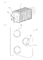
- FIG. 1 is a perspective view of a heat exchanger according to Embodiment 1 and a cross-sectional view of a heat transfer tube showing the heat exchanger in an enlarged manner.
- a heat exchanger 1 is a fin-tube heat exchanger widely used as an evaporator or condenser such as a refrigeration apparatus or an air conditioner, and is a direction orthogonal to the air flow direction.
- fins 10 stacked on each other, and, for example, a perfect circle heat transfer tube 20 fixed through the fins 10.
- the fin 10 is made of, for example, an aluminum-based material having low deformation resistance
- the heat transfer tube 20 is made of, for example, an aluminum-based material having higher deformation resistance than the aluminum-based material forming the fin 10.
- the heat transfer tube 20 is a component of the refrigerant circuit in the refrigeration cycle apparatus.
- the inner surface is provided with a plurality of protrusions 22 protruding toward the axial center on the inner surface (see FIG. 1B), and the refrigerant is contained in the tube. Flows.
- the heat transfer area serving as a contact surface with the air is expanded, and heat exchange between the refrigerant and the air is performed. It can be done efficiently.
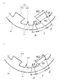
- FIG. 2 is a partial cross-sectional view showing a further enlarged portion A of the heat transfer tube of FIG.
- (a) in a figure shows the state before pipe expansion of the heat exchanger tube 20, (b) shows the state after pipe expansion of the heat exchanger tube 20.
- FIG. On the inner surface of the heat transfer tube 20 in the present embodiment a plurality of grooves 21 and protrusions 22 extending in the axial direction of the heat transfer tube 20 are formed in the circumferential direction by groove forming as shown in FIG. Is provided.
- the plurality of protrusions 22 protrude toward the axial center of the heat transfer tube 20, and, for example, the first protrusion 22A (hereinafter referred to as “high protrusion 22A”) having a flat tip and the tip
- the portion is composed of two types of second protrusions 22B (hereinafter referred to as “low protrusions 22B”) having acute angles.
- the height h of the low protrusion 22B is, for example, 0.06 mm or more lower than the height H of the high protrusion 22A before the heat transfer tube 20 is expanded.
- H ⁇ h difference between the high protrusion 22A and the low protrusion 22B, or the low protrusion 22B is too low
- the heat transfer performance such as a decrease in the surface area of the heat transfer tube 20 is obtained. May be reduced. Therefore, in the present embodiment, the difference is set to be close to 0.06 mm.
- this dimension is an example and is not limited, It changes with the magnitude
- the high protrusion 22A is formed in an inverted trapezoidal shape in which the tip width W2 is wider than the root width W1.
- the low protrusion 22B is formed in a triangular shape whose side surfaces become thinner as it goes from the root to the tip.
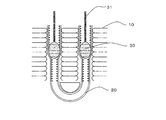
- FIG. 3 is a cross-sectional view showing the expanded state of the heat transfer tube by the mechanical expansion method.
- the heat transfer tube 20 in the present embodiment is first bent into a hairpin shape at a predetermined bending pitch at the central portion in the longitudinal direction (axial direction) to produce a plurality of hairpin tubes to be the heat transfer tubes 20. After allowing the hairpin tube to pass through the through holes provided in each fin 10, the hairpin tube is expanded by a mechanical tube expansion method to form a heat transfer tube 20, and the heat transfer tube 20 is brought into close contact with each fin 10 and joined.
- the above-mentioned mechanical tube expansion method is a method in which a rod 31 having a tube ball 30 having a diameter slightly larger than the inner diameter of the heat transfer tube 20 is passed through the tube of the heat transfer tube 20 to expand the outer diameter of the heat transfer tube 20. 10.
- a hydraulic pressure expansion method in which the tube expansion ball 30 is pushed into the tube by liquid pressure to expand the heat transfer tube 20.
- the tip width W2 of the high protrusion 22A is an inverted trapezoidal shape wider than the root width W1
- the area where the expanded ball 30 contacts the high protrusion 22A is large.
- the tip of the protrusion 22A is flattened by approximately 0.06 mm, and the height H of the high protrusion 22A is reduced.
- the apex angle ⁇ which is the intersection angle between both side surfaces of the high protrusion 22A, becomes smaller than that before the heat transfer tube 20 is expanded.
- the height h of the low protrusion 22B is lower than the crushed height 0.06m, so there is no deformation.
- the insertion pressure of the expanded ball 30 is not applied to all the protrusions 22 in the tube as in the prior art, but the tube is expanded by applying pressure to the tip of the high protrusion 22A.
- the outer surface of the heat transfer tube 20 formed in is processed into a polygon. Thereby, the spring back of the heat transfer tube 20 can be suppressed, the adhesion between the heat transfer tube 20 and each fin 10 can be improved, and the heat exchange efficiency can be increased.
- the opposite side surfaces of the high protrusion 22A and the low protrusion 22B after the expansion of the heat transfer tube 20 are formed so as to be inclined so that the extension lines of the both sides intersect the heat transfer tube 20 inside.
- the crossing angle (vertical angle ⁇ ) formed by extending the extension lines on both sides is, for example, in the range of 2 degrees to 12 degrees.
- the apex angle ⁇ after the expansion of the heat transfer tube 20 is wider than the apex angle ⁇ before the expansion.
- the apex angle ⁇ is in the range of 2 degrees to 12 degrees, for example. However, this is different depending on the outer diameter of the heat transfer tube 20 and is not limited.
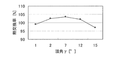
- FIG. 4 is a graph showing the relationship between the apex angle ⁇ , which is the intersection angle between the opposite side surfaces of the high and low protrusions after pipe expansion, and the heat exchange rate.
- the apex angle ⁇ which is the crossing angle between the opposite side surfaces of the high protrusion 22A and the low protrusion 22B after the pipe expansion, is in the range of, for example, 2 ° to 12 ° (predetermined) Angle range).
- the apex angle ⁇ which is the intersection angle between the opposite side surfaces of the high protrusion 22A and the low protrusion 22B after the expansion of the heat transfer tube 20, is in the range of 2 degrees to 12 degrees.
- the reason for this is that when the heat transfer tube 20 is expanded, the expanded ball 30 comes into contact with the high protrusion 22A and its tip is crushed by 0.06 mm to reduce the height H of the protrusion. This is because if the angle ⁇ is smaller than 2 degrees, the boiling promotion effect cannot be obtained and the in-tube evaporation heat transfer performance is lowered.
- apex angle ⁇ which is the crossing angle between the opposite side surfaces of the high protrusion 22A and the low protrusion 22B after the pipe expansion, is greater than 12 degrees, a refrigerant is introduced into the space between the high protrusion 22A and the low protrusion 22B. This is because it becomes difficult to flow, and the condensation / evaporation heat transfer performance in the pipe is lowered.
- the difference between the height H of the high protrusion 22A and the height h of the low protrusion 22B provided in the heat transfer tube 20 is set to 0.06 mm or more.
- the tip width W2 of the portion 22A is an inverted trapezoid wider than the root width W1
- the low protrusion 22B is triangular, and the heat transfer tube 20 is expanded by a mechanical expansion method, the high protrusion 22A and the low protrusion 22B
- the apex angle ⁇ which is the crossing angle between the opposite side surfaces of each other, is formed in the range of 2 to 12 degrees. Thereby, the heat transfer performance in the heat transfer tube 20 can be improved.
- the pipe expansion ball 30 contacts only the tip of the high protrusion 22A and expands the tube, the outer surface of the heat transfer tube 20 is processed into a polygon, and the spring back of the heat transfer tube 20 can be suppressed. Therefore, the adhesion between the heat transfer tubes 20 and the fins 10 can be improved, the heat exchange rate (the ratio of the amount of heat before and after passing through the heat transfer tubes) can be increased, and energy saving can be achieved. Further, it is possible to reduce the size of the refrigerant in the refrigerant circuit while maintaining a reduced amount of the refrigerant and high efficiency.
- the apex angle ⁇ which is the intersection angle between the opposite side surfaces of the high protrusion 22A and the low protrusion 22B, is in the range of 2 degrees to 12 degrees.
- the range of the apex angle ⁇ is not limited.
- the aforementioned apex angle ⁇ may be in the range of 3 degrees to 10 degrees.
- the evaporation heat transfer performance can be further improved as compared with the heat transfer tube 20 in which the apex angle ⁇ is in the range of 2 to 12 degrees.
- Embodiment 2 shown in FIG. 2 (b), the tip end width W2 and the root are set so that the tip end width W2 of the high protrusion 22A after expansion of the heat transfer tube 20 is in the range of 0.28 mm to 0.46 mm.
- the apex angle ⁇ which is the intersection angle of both side surfaces of the low protrusion 22B after the expansion of the heat transfer tube 20, is set so that the ratio W2 / W1 to the width W1 is, for example, in the range of 1.15 to 1.92.
- the angle is set to 5 degrees to 15 degrees.
- the high protrusion 22A has a ratio W2 / W1 between the tip end width W2 and the root width W1 after the expansion of the heat transfer tube 20 in a range of 1.15 to 1.92, thereby increasing the height of the protrusion 22A. It becomes easy for the refrigerant to flow between the front end portion of the protrusion and the front end portion of the low protrusion 22B. Therefore, the boiling promotion effect is obtained and the in-pipe evaporation heat transfer performance is increased.
- the ratio W2 / W1 between the tip width W2 and the root width W1 is smaller than 1.15, the boiling promotion effect cannot be obtained, and the evaporation heat transfer performance in the tube is lowered.
- the ratio W2 / W1 is larger than 1.92, the refrigerant hardly flows into the groove 21 (space) between the high protrusion 22A and the low protrusion 22B, and the in-tube evaporation heat transfer performance is improved. descend.
- the ratio W2 / W1 between the tip end width W2 and the root width W1 after the expansion of the heat transfer tube 20 is in the range of 1.15 to 1.92, and the heat transfer tube 20
- the high protrusion 22A before the expansion of the heat transfer tube 20 is formed so that the tip width W2 of the high protrusion 22A after the tube expansion is in the range of 0.28 mm to 0.46 mm.
- the evaporation heat transfer performance after the expansion of the heat transfer tube 20 is further improved.
- the low protrusion 22B is a refrigerant generated in the grooves 21 on both sides of the low protrusion 22B by allowing the apex angle ⁇ , which is the crossing angle of both sides, to be 5 to 15 degrees after the heat transfer tube 20 is expanded.
- the condensed liquid film becomes thinner, and the condensation heat transfer performance in the tube increases.
- the apex angle ⁇ which is the crossing angle between the two side surfaces of the low protrusion 22B, is smaller than 5 degrees, the refrigerant condensate liquid film becomes thick, and the condensing heat transfer performance in the tube deteriorates.
- the apex angle ⁇ is larger than 15 degrees, the heat transfer area of the groove 21 between the high protrusion 22A and the low protrusion 22B decreases, and the in-tube condensation / evaporation heat transfer performance decreases.
- the low angle before the heat transfer tube 20 is expanded so that the apex angle ⁇ , which is the intersection angle of both side surfaces of the low protrusion 22B, is in the range of 5 to 15 degrees.
- the protrusion 22B is formed. The reason why the apex angle ⁇ of the low protrusion 22B is in the range of 5 to 15 degrees is that the diameter of the heat transfer tube 20 is expanded by the expansion of the heat transfer tube 20 (see FIGS. 2A and 2B).
- the tip width W2 and the root width W1 of the high protrusion 22A after expansion of the heat transfer tube 20 are in the range of 0.28 mm to 0.46 mm.
- the ratio W2 / W1 is in the range of 1.15 to 1.92, and after the heat transfer tube 20 is expanded, the apex angle ⁇ , which is the crossing angle of both side surfaces of the low protrusion 22B, is 5 degrees to 15 degrees.
- a high protrusion 22A and a low protrusion 22B are formed. Thereby, the heat transfer performance in the heat transfer tube 20 can be improved.
- the tip width W2 and the root width W1 are set such that the tip width W2 of the high protrusion 22A after expansion of the heat transfer tube 20 is in the range of 0.28 mm to 0.46 mm.
- the apex angle ⁇ which is the crossing angle between the two side surfaces of the low protrusion 22B after the expansion of the heat transfer tube 20, is set so that the ratio W2 / W1 is in the range of, for example, 1.15 to 1.92. However, this differs depending on the outer diameter of the heat transfer tube 20, and is not limited.
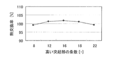
- FIG. 5 is a diagram showing the relationship between the number of high protrusions of the heat transfer tube and the heat exchange rate in the heat exchanger of the third embodiment.
- the heat exchange rate exceeds 100% as shown in FIG. Note that when the number of high protrusions 22A is 13 to 17, the heat exchange rate is further improved. In this case, the low protrusions 22B between the high protrusions 22A are two to four.
- the high protrusion 22A of the heat transfer tube 20 is set in the range of 12 to 18 because when the heat transfer tube 20 is expanded, the expanded ball 30 comes into contact with the high protrusion 22A and the tip portion is 0. This is because it is flattened by being crushed by 06 mm, and its height H is lowered. In other words, only the tip of the high protrusion 22A is crushed by 0.06 mm without the low protrusion 22B provided between the high protrusions 22A being crushed. In that case, the ratio W2 / W1 between the tip width W2 and the root width W1 after the expansion of the heat transfer tube 20 is in the range of 1.15 to 1.92, and the high protrusion 22A after the expansion of the heat transfer tube 20 is performed.
- the tip end width W2 is in the range of 0.28 mm to 0.46 mm.
- the tip of the low protrusion 22B is crushed and flattened, the heat transfer performance in the tube is lowered, and the high protrusion 22A.
- the number of strips is increased from 18, the number of strips of the low protrusions 22B is decreased, and the heat transfer performance in the tube is lowered.
- the heat transfer performance of the heat transfer tube 20 is improved by setting the high protrusion 22A of the heat transfer tube 20 in the range of 12 to 18.
- the high protrusion 22A provided in the heat transfer tube 20 is in the range of 12 to 18, but this differs depending on the outer diameter of the heat transfer tube 20 and is limited. Is not to be done.
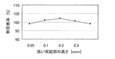
- the height h of the low protrusion 22B provided on the inner surface of the heat transfer tube 20 is in the range of 0.1 mm to 0.3 mm, for example.
- FIG. 6 is a diagram showing the relationship between the height of the low protrusion after expansion of the heat transfer tube and the heat exchange rate in the heat exchanger of the fourth embodiment.
- the heat exchange rate exceeds 100%.
- the apex angle ⁇ which is the crossing angle between both side surfaces of the low protrusion 22B, is 5 degrees to 15 degrees.
- the heat exchange rate is further improved.
- the heat transfer rate decreases. Further, when the height h of the low protrusion 22B is lower than 0.1 mm, the heat transfer rate is not improved.
- the low protrusion 22B is formed so that the height h of the low protrusion 22B after expansion of the heat transfer tube 20 is 0.1 mm to 0.3 mm, the pressure loss is increased.
- the heat transfer performance in the heat transfer tube 20 can be improved.
- the height h of the low protrusion 22B provided in the heat transfer tube 20 is in the range of 0.1 mm to 0.3 mm, but this is the size of the outer diameter of the heat transfer tube 20. It depends on the situation and is not limited.
- FIG. FIG. 7 is a refrigerant circuit diagram of the air-conditioning apparatus according to Embodiment 5.
- the air conditioning apparatus according to the present embodiment includes the refrigeration cycle apparatus including the heat exchanger according to any of the first to fourth embodiments described above, and includes the outdoor unit 100 of the heat source side unit, and the refrigerant pipe 300 to the outdoor unit 100. , 400 and the indoor unit 200 of the load side unit connected through 400.
- a pipe through which a gaseous refrigerant (gas refrigerant) flows is referred to as a gas pipe 300
- a pipe through which a liquid refrigerant (in some cases, a liquid refrigerant or a gas-liquid two-phase refrigerant) flows is referred to as a liquid pipe 400.
- R32 is used as the refrigerant. Since the strength of the aluminum material is low, the thickness of the groove bottom of the heat transfer tube is increased, so that the pressure loss in the tube of the heat transfer tube increases. When the refrigerant R32 having a small in-pipe pressure loss is used, the heat transfer performance in the evaporating pipe can be improved without increasing the pressure loss, and therefore a highly efficient heat exchanger can be provided.
- the outdoor unit 100 includes a compressor 101, an oil separator 102, a four-way valve 103, an outdoor heat exchanger 104, an outdoor blower fan 105, an accumulator (liquid separator) 106, a throttling device (expansion valve) 107, and an inter-refrigerant heat exchanger. 108, a bypass throttle device 109, an outdoor control device 110, and the like.
- the compressor 101 sucks the refrigerant in the accumulator 106, compresses the refrigerant, and flows it into the refrigerant pipe as a high-temperature / high-pressure gas refrigerant.
- operation control of the compressor 101 for example, an inverter circuit or the like is provided in the compressor 101, and the capacity (discharge refrigerant amount per unit time) of the compressor 101 is finely changed by arbitrarily changing the operation frequency. Shall be able to.
- the oil separator 102 is for separating the lubricating oil discharged from the compressor 101 mixed with the refrigerant.
- the separated lubricating oil is returned to the compressor 101.
- the four-way valve 103 switches the refrigerant flow based on an instruction from the outdoor control device 110, and switches between the cooling operation and the heating operation.
- the outdoor heat exchanger 104 the heat exchanger 1 described in Embodiments 1 to 4 is used, and heat exchange is performed between the refrigerant and air (outdoor air).
- the outdoor heat exchanger 104 functions as an evaporator during heating operation, performs heat exchange between the low-pressure refrigerant flowing in through the expansion device 107 and the air, and evaporates and vaporizes the refrigerant.
- the outdoor heat exchanger 104 functions as a condenser during the cooling operation, and performs heat exchange between the high-temperature and high-pressure gas refrigerant from the compressor 101 flowing in via the four-way valve 103 and the air to condense the refrigerant. Liquefy.
- the outdoor blower fan 105 is provided so that heat exchange with the refrigerant in the outdoor heat exchanger 104 can be performed efficiently.
- an inverter circuit (not shown) that can arbitrarily control the rotational speed of the fan by arbitrarily changing the operating frequency of the fan motor may be used.
- the inter-refrigerant heat exchanger 108 exchanges heat between the refrigerant flowing in the main flow path of the refrigerant circuit and the refrigerant branched from the flow path and adjusted in flow rate by the bypass expansion device 109 (expansion valve). .
- the refrigerant is supercooled and supplied to the indoor unit 200.
- the inter-refrigerant heat exchanger 108 the heat exchanger 1 described in the first to fourth embodiments is used.
- the liquid flowing through the bypass throttle device 109 is returned to the accumulator 106 via the bypass pipe 107.
- the accumulator 106 is means for storing, for example, a liquid surplus refrigerant.
- the outdoor control device 110 is composed of, for example, a microcomputer and can communicate with the indoor control device 204 by wire or wirelessly. For example, based on data relating to detection by various detection means (sensors) in the air conditioner, an inverter The operation control of the entire air conditioner is performed by controlling each means related to the air conditioner such as the operation frequency control of the compressor 101 by the control of the circuit.
- the indoor unit 200 includes an indoor heat exchanger 201, a throttle device (expansion valve) 202, an indoor fan 203, an indoor control device 204, and the like. Also for the indoor heat exchanger 201, the heat exchanger 1 described in the first to fourth embodiments is used, and heat exchange is performed between the refrigerant and the air in the space to be air-conditioned.
- the indoor heat exchanger 201 functions as a condenser during the heating operation, performs heat exchange between the refrigerant flowing in from the gas pipe 300 and air, condenses the refrigerant and liquefies (or gas-liquid two-phase), and the liquid pipe It flows out to the 400 side. Further, the indoor heat exchanger 201 functions as an evaporator during cooling operation, performs heat exchange between the refrigerant and the air whose pressure is reduced by the expansion device 202, and evaporates by evaporating the refrigerant by taking heat of the air. And flow out to the gas pipe 300 side.
- the indoor blower fan 203 is a fan for adjusting the flow of air for heat exchange, and the operation speed is determined by, for example, user settings.
- the expansion device 202 adjusts the pressure of the refrigerant in the indoor heat exchanger 201 by changing the opening degree.
- the indoor control device 204 is composed of a microcomputer or the like, and communicates with the outdoor control device 110 in a wired or wireless manner as described above. Based on an instruction from the outdoor control device 110, that is, a remote control operation from a resident or the like, for example, each device (means) of the indoor unit 200 is controlled so that the room has a predetermined temperature.
- the indoor control device 204 also transmits to the outdoor control device 110 a signal including data related to detection by a detection unit provided in the indoor unit 200.
- the operation of the air conditioner will be described.
- the high-temperature and high-pressure gas refrigerant discharged from the compressor 101 is condensed by passing through the outdoor heat exchanger 104 from the four-way valve 103 and flows out of the outdoor unit 100 as a liquid refrigerant.
- the liquid refrigerant that has flowed out of the outdoor unit 100 flows into the indoor unit 200 through the liquid pipe 400, becomes a low-temperature / low-pressure liquid refrigerant whose pressure is adjusted by adjusting the opening degree of the expansion device 202, and passes through the indoor heat exchanger 201. Pass through and evaporate.
- the gas refrigerant flows into the outdoor unit 100 through the gas pipe 300, is sucked into the compressor 101 through the four-way valve 103 and the accumulator 106, is pressurized again, and circulates as a high-temperature / high-pressure gas refrigerant. .
- the compressor 101 Due to the operation of the compressor 101, the high-temperature and high-pressure gas refrigerant discharged from the compressor 101 flows into the indoor unit 200 from the four-way valve 103 through the gas pipe 300.
- the pressure is adjusted by adjusting the opening degree of the expansion device 202, the condensation is performed by passing through the indoor heat exchanger 201, and the refrigerant becomes an intermediate-pressure liquid or a gas-liquid two-phase refrigerant. Spill.
- the refrigerant that has flowed out of the indoor unit 200 flows into the outdoor unit 100 through the liquid pipe 400, is pressure-adjusted by adjusting the opening degree of the expansion device 107, evaporates by passing through the outdoor heat exchanger 104, and gas refrigerant Then, it is sucked into the compressor 101 through the four-way valve 103 and the accumulator 106, and is pressurized again as described above to circulate as a high-temperature / high-pressure gas refrigerant.
- the outdoor heat exchanger 104, the inter-refrigerant heat exchanger 108, and the indoor heat exchanger 201 of the indoor unit 200 have a high heat exchange rate in the first to fourth embodiments.
- the heat exchanger 1 is used. Therefore, COP (CoefficientCoof Performance: energy consumption efficiency, coefficient of performance) and the like can be improved, and energy saving can be achieved.
- W1 and W2 shown in each table are the tip width and the root width of the high protrusion 22A, and ⁇ is an apex angle that is an intersection angle of both side surfaces of the low protrusion 22B. ⁇ is an apex angle that is an intersection angle between opposite side surfaces of the high protrusion 22A and the low protrusion 22B, and W2 / W1 is a ratio of the tip width W2 and the root width W1.
- surface is a value after the heat exchanger tube 20 is expanded.
- the root width W1 of the high protrusion 22A formed on the inner surface of the heat transfer tube 20 is 0.26 mm
- the apex angle ⁇ of the low protrusion 22B is 15 degrees
- the apex angle ⁇ is 2
- the heat exchanger 1 which is 7 and 12 was produced (Examples 1, 2 and Example 3).
- a heat exchanger in which the root width W1 of the high protrusion 22A is 0.26 mm, the apex angle ⁇ of the low protrusion 22B is 15 degrees, and the apex angle ⁇ is 1 and 15 is manufactured ( Comparative Example 1 and Comparative Example 2).
- the apex angle ⁇ of the low protrusion 22B is 10 degrees, and the ratio W2 / W1 between the tip width W2 and the root width W1 of the high protrusion 22A is 1.15 and 1.
- a heat exchanger 1 of .92 was produced (Example 4 and Example 5).
- the apex angle ⁇ of the low protrusion 22B is 10 degrees, and the ratio W2 / W1 between the tip width W2 and the root width W1 of the high protrusion 22A is 1.0 and 2.0.
- a heat exchanger was produced (Comparative Example 3 and Comparative Example 4).
- Example 4 both have a heat exchange rate higher than 100% compared with the heat exchangers of Comparative Example 3 and Comparative Example 4, Heat transfer performance was improved.
- the tip width W2 of the high protrusion 22A is 0.28 mm
- the root width W1 is 0.26 mm
- the apex angle ⁇ of the low protrusion 22B is 5 degrees, 10 degrees
- the heat exchanger 1 which is 15 degrees was produced (Examples 6 and 7 and Example 8).
- a heat exchanger in which the tip end width W2 of the high protrusion 22A is 0.28 mm, the root width W1 is 0.26 mm, and the apex angle ⁇ of the low protrusion 22B is 0 degrees and 20 degrees. (Comparative Example 5 and Comparative Example 6).
- the heat exchangers 1 of Examples 6, 7 and 8 all have a heat exchange rate higher than 100% compared to the heat exchangers of Comparative Example 5 and Comparative Example 6. The heat transfer performance in the pipe was improved.
- the tip width W2 of the high protrusion 22A is 0.28 mm
- the root width W1 is 0.26 mm
- the apex angle ⁇ of the low protrusion 22B is 15 degrees, which is high.
- Heat exchanger 1 in which the number of protrusions 22A was 12, 16, and 18 was produced (Examples 9, 10 and Example 11).
- the tip width W2 of the high protrusion 22A is 0.28 mm
- the root width W1 is 0.26 mm
- the apex angle ⁇ of the low protrusion 22B is 15 degrees
- the high protrusion 22A Heat exchangers with 8 and 22 strips were produced (Comparative Example 7 and Comparative Example 8).
- the heat exchangers 1 of Examples 9, 10 and 11 all have a heat exchange rate higher than 100% compared to the heat exchangers of Comparative Example 7 and Comparative Example 8. The heat transfer performance in the pipe was improved.
- the tip width W2 of the high protrusion 22A is 0.28 mm
- the root width W1 is 0.26 mm
- the apex angle ⁇ of the low protrusion 22B is 15 degrees, which is low.
- the heat exchanger 1 in which the height h of the protrusion 22B was 0.1 mm, 0.2 mm, and 0.3 mm was produced (Examples 12, 13, and Example 14).
- the tip width W2 of the high protrusion 22A is 0.28 mm
- the root width W1 is 0.26 mm
- the apex angle ⁇ of the low protrusion 22B is 15 degrees
- the low protrusion 22B Heat exchangers having a height h of 0.05 mm and 0.4 mm were produced (Comparative Example 9 and Comparative Example 10).
- the heat exchangers 1 of Examples 12, 13 and 14 all have a heat exchange rate higher than 100% compared to the heat exchangers of Comparative Example 9 and Comparative Example 10. The heat transfer performance in the pipe was improved.
- the present invention is not limited to these devices, and may be applied to other refrigeration cycle devices having a heat exchanger that constitutes a refrigerant circuit, such as a refrigeration device, a heat pump device, and the like, and has an evaporator and a condenser. be able to.
Landscapes
- Engineering & Computer Science (AREA)
- Physics & Mathematics (AREA)
- Thermal Sciences (AREA)
- Mechanical Engineering (AREA)
- General Engineering & Computer Science (AREA)
- Geometry (AREA)
- Heat-Exchange Devices With Radiators And Conduit Assemblies (AREA)
Priority Applications (6)
| Application Number | Priority Date | Filing Date | Title |
|---|---|---|---|
| JP2013535815A JP5800909B2 (ja) | 2011-09-26 | 2012-01-30 | 熱交換器及びその熱交換器を用いた冷凍サイクル装置 |
| CN201280046842.XA CN103842760B (zh) | 2011-09-26 | 2012-01-30 | 换热器及使用该换热器的制冷循环装置 |
| IN2744CHN2014 IN2014CN02744A (es) | 2011-09-26 | 2012-01-30 | |
| EP12835922.1A EP2765383B1 (en) | 2011-09-26 | 2012-01-30 | Heat exchanger and refrigeration cycle device using heat exchanger |
| US14/241,479 US9879921B2 (en) | 2011-09-26 | 2012-01-30 | Heat exchanger and refrigeration cycle device including the heat exchanger |
| ES12835922T ES2731748T3 (es) | 2011-09-26 | 2012-01-30 | Intercambiador de calor y dispositivo de ciclo de refrigeración que incluye el intercambiador de calor |
Applications Claiming Priority (2)
| Application Number | Priority Date | Filing Date | Title |
|---|---|---|---|
| JP2011-209165 | 2011-09-26 | ||
| JP2011209165 | 2011-09-26 |
Publications (1)
| Publication Number | Publication Date |
|---|---|
| WO2013046482A1 true WO2013046482A1 (ja) | 2013-04-04 |
Family
ID=47994579
Family Applications (1)
| Application Number | Title | Priority Date | Filing Date |
|---|---|---|---|
| PCT/JP2012/000577 WO2013046482A1 (ja) | 2011-09-26 | 2012-01-30 | 熱交換器及びその熱交換器を用いた冷凍サイクル装置 |
Country Status (7)
| Country | Link |
|---|---|
| US (1) | US9879921B2 (es) |
| EP (1) | EP2765383B1 (es) |
| JP (1) | JP5800909B2 (es) |
| CN (1) | CN103842760B (es) |
| ES (1) | ES2731748T3 (es) |
| IN (1) | IN2014CN02744A (es) |
| WO (1) | WO2013046482A1 (es) |
Cited By (4)
| Publication number | Priority date | Publication date | Assignee | Title |
|---|---|---|---|---|
| CN104515425A (zh) * | 2013-09-27 | 2015-04-15 | 安徽明腾永磁机电设备有限公司 | 一种基于紊流原理的热交换风管 |
| JP2018091552A (ja) * | 2016-12-02 | 2018-06-14 | 株式会社Uacj | 内面溝付管 |
| WO2021132310A1 (ja) * | 2019-12-27 | 2021-07-01 | 株式会社クボタ | 流体撹拌要素を具える熱分解管 |
| US11125505B2 (en) | 2017-09-19 | 2021-09-21 | Samsung Electronics Co., Ltd. | Heat exchanger and air conditioner including the same |
Families Citing this family (5)
| Publication number | Priority date | Publication date | Assignee | Title |
|---|---|---|---|---|
| EP3207322A1 (de) * | 2014-10-13 | 2017-08-23 | Güntner GmbH & Co. KG | Verfahren zum betreiben eines wärmeaustauschsystems und wärmeaustauschsystem |
| CN108344322B (zh) * | 2018-03-28 | 2023-12-15 | 长沙格力暖通制冷设备有限公司 | 翅片换热器及空调器 |
| US11774187B2 (en) * | 2018-04-19 | 2023-10-03 | Kyungdong Navien Co., Ltd. | Heat transfer fin of fin-tube type heat exchanger |
| CA3137969A1 (en) * | 2019-05-03 | 2020-11-12 | Hydro Extrusion USA, LLC | Ribbed extruded electrical conduit |
| US11781814B2 (en) * | 2020-03-16 | 2023-10-10 | The Boeing Company | Tapered groove width heat pipe |
Citations (5)
| Publication number | Priority date | Publication date | Assignee | Title |
|---|---|---|---|---|
| JPS63172893A (ja) * | 1987-01-12 | 1988-07-16 | Matsushita Refrig Co | 内面溝付伝熱管 |
| JPS63290395A (ja) * | 1987-05-22 | 1988-11-28 | Hitachi Ltd | 内面溝付伝熱管 |
| JP2001289585A (ja) | 2000-04-05 | 2001-10-19 | Mitsubishi Alum Co Ltd | 内面溝付きアルミニウム管およびこれを用いた熱交換器 |
| JP2002081882A (ja) * | 2000-08-31 | 2002-03-22 | Matsushita Electric Ind Co Ltd | 熱交換器とその製造方法 |
| WO2009131072A1 (ja) * | 2008-04-24 | 2009-10-29 | 三菱電機株式会社 | 熱交換器、及びこの熱交換器を用いた空気調和機 |
Family Cites Families (15)
| Publication number | Priority date | Publication date | Assignee | Title |
|---|---|---|---|---|
| JPS54147751U (es) | 1978-04-06 | 1979-10-15 | ||
| JP2638223B2 (ja) | 1989-10-18 | 1997-08-06 | 三菱マテリアル株式会社 | 偏平溝付管及びその製造方法 |
| JPH06101986A (ja) * | 1992-09-17 | 1994-04-12 | Mitsubishi Shindoh Co Ltd | 内面溝付伝熱管 |
| JPH08128793A (ja) * | 1994-10-28 | 1996-05-21 | Toshiba Corp | 内部フィン付伝熱管とその製造方法 |
| US6176302B1 (en) * | 1998-03-04 | 2001-01-23 | Kabushiki Kaisha Kobe Seiko Sho | Boiling heat transfer tube |
| JP2000121272A (ja) | 1998-10-14 | 2000-04-28 | Mitsubishi Shindoh Co Ltd | 内面溝付伝熱管および熱交換器 |
| JP4294183B2 (ja) * | 1999-11-08 | 2009-07-08 | 住友軽金属工業株式会社 | 内面溝付伝熱管 |
| US6883597B2 (en) * | 2001-04-17 | 2005-04-26 | Wolverine Tube, Inc. | Heat transfer tube with grooved inner surface |
| JP2004003733A (ja) * | 2002-05-31 | 2004-01-08 | Mitsubishi Heavy Ind Ltd | 伝熱管及び熱交換器、伝熱管の製造方法 |
| JP4597475B2 (ja) * | 2002-12-12 | 2010-12-15 | 住友軽金属工業株式会社 | 熱交換器用クロスフィンチューブの製造方法及びクロスフィン型熱交換器 |
| US20050126757A1 (en) * | 2003-12-16 | 2005-06-16 | Bennett Donald L. | Internally enhanced tube with smaller groove top |
| JP4550451B2 (ja) * | 2004-03-11 | 2010-09-22 | 古河電気工業株式会社 | 内面溝付伝熱管及び内面溝付伝熱管を用いた熱交換器 |
| JP4665713B2 (ja) | 2005-10-25 | 2011-04-06 | 日立電線株式会社 | 内面溝付伝熱管 |
| JP2010038502A (ja) | 2008-08-08 | 2010-02-18 | Mitsubishi Electric Corp | 熱交換器用の伝熱管、熱交換器、冷凍サイクル装置及び空気調和装置 |
| JP2010133668A (ja) * | 2008-12-05 | 2010-06-17 | Kobelco & Materials Copper Tube Inc | 内面溝付伝熱管及び熱交換器 |
-
2012
- 2012-01-30 ES ES12835922T patent/ES2731748T3/es active Active
- 2012-01-30 JP JP2013535815A patent/JP5800909B2/ja active Active
- 2012-01-30 CN CN201280046842.XA patent/CN103842760B/zh active Active
- 2012-01-30 US US14/241,479 patent/US9879921B2/en active Active
- 2012-01-30 EP EP12835922.1A patent/EP2765383B1/en active Active
- 2012-01-30 WO PCT/JP2012/000577 patent/WO2013046482A1/ja active Application Filing
- 2012-01-30 IN IN2744CHN2014 patent/IN2014CN02744A/en unknown
Patent Citations (5)
| Publication number | Priority date | Publication date | Assignee | Title |
|---|---|---|---|---|
| JPS63172893A (ja) * | 1987-01-12 | 1988-07-16 | Matsushita Refrig Co | 内面溝付伝熱管 |
| JPS63290395A (ja) * | 1987-05-22 | 1988-11-28 | Hitachi Ltd | 内面溝付伝熱管 |
| JP2001289585A (ja) | 2000-04-05 | 2001-10-19 | Mitsubishi Alum Co Ltd | 内面溝付きアルミニウム管およびこれを用いた熱交換器 |
| JP2002081882A (ja) * | 2000-08-31 | 2002-03-22 | Matsushita Electric Ind Co Ltd | 熱交換器とその製造方法 |
| WO2009131072A1 (ja) * | 2008-04-24 | 2009-10-29 | 三菱電機株式会社 | 熱交換器、及びこの熱交換器を用いた空気調和機 |
Cited By (6)
| Publication number | Priority date | Publication date | Assignee | Title |
|---|---|---|---|---|
| CN104515425A (zh) * | 2013-09-27 | 2015-04-15 | 安徽明腾永磁机电设备有限公司 | 一种基于紊流原理的热交换风管 |
| CN104515425B (zh) * | 2013-09-27 | 2016-06-22 | 安徽明腾永磁机电设备有限公司 | 一种基于紊流原理的热交换风管 |
| JP2018091552A (ja) * | 2016-12-02 | 2018-06-14 | 株式会社Uacj | 内面溝付管 |
| US11125505B2 (en) | 2017-09-19 | 2021-09-21 | Samsung Electronics Co., Ltd. | Heat exchanger and air conditioner including the same |
| WO2021132310A1 (ja) * | 2019-12-27 | 2021-07-01 | 株式会社クボタ | 流体撹拌要素を具える熱分解管 |
| JPWO2021132310A1 (ja) * | 2019-12-27 | 2021-12-23 | 株式会社クボタ | 流体撹拌要素を具える熱分解管 |
Also Published As
| Publication number | Publication date |
|---|---|
| JP5800909B2 (ja) | 2015-10-28 |
| US20140223956A1 (en) | 2014-08-14 |
| CN103842760B (zh) | 2016-07-06 |
| ES2731748T3 (es) | 2019-11-18 |
| JPWO2013046482A1 (ja) | 2015-03-26 |
| EP2765383B1 (en) | 2019-05-22 |
| EP2765383A1 (en) | 2014-08-13 |
| IN2014CN02744A (es) | 2015-07-03 |
| CN103842760A (zh) | 2014-06-04 |
| US9879921B2 (en) | 2018-01-30 |
| EP2765383A4 (en) | 2015-07-08 |
Similar Documents
| Publication | Publication Date | Title |
|---|---|---|
| JP5800909B2 (ja) | 熱交換器及びその熱交換器を用いた冷凍サイクル装置 | |
| WO2011086881A1 (ja) | 熱交換器用の伝熱管、熱交換器、冷凍サイクル装置及び空気調和装置 | |
| WO2010016516A1 (ja) | 熱交換器用の伝熱管、熱交換器、冷凍サイクル装置及び空気調和装置 | |
| JP2009133500A (ja) | 空気調和機 | |
| WO2021065913A1 (ja) | 蒸発器、およびそれを備えた冷凍サイクル装置 | |
| US9506700B2 (en) | Air-conditioning apparatus | |
| JP5646257B2 (ja) | 冷凍サイクル装置 | |
| JP6104357B2 (ja) | 熱交換装置およびこれを備えた冷凍サイクル装置 | |
| JP7118247B2 (ja) | 空気調和機 | |
| WO2015125525A1 (ja) | 熱交換器及び冷凍サイクル装置 | |
| WO2021176651A1 (ja) | 熱交換器及び空気調和機 | |
| JP4983878B2 (ja) | 熱交換器及びこの熱交換器を備えた冷蔵庫、空気調和機 | |
| JP6925508B2 (ja) | 熱交換器、冷凍サイクル装置および空気調和装置 | |
| JP2010249484A (ja) | 熱交換器および冷凍サイクル装置 | |
| JP2003262433A (ja) | 熱交換器 | |
| JPH0979779A (ja) | 内面溝付伝熱管及び熱交換器 |
Legal Events
| Date | Code | Title | Description |
|---|---|---|---|
| 121 | Ep: the epo has been informed by wipo that ep was designated in this application |
Ref document number: 12835922 Country of ref document: EP Kind code of ref document: A1 |
|
| ENP | Entry into the national phase |
Ref document number: 2013535815 Country of ref document: JP Kind code of ref document: A |
|
| WWE | Wipo information: entry into national phase |
Ref document number: 14241479 Country of ref document: US |
|
| NENP | Non-entry into the national phase |
Ref country code: DE |
|
| WWE | Wipo information: entry into national phase |
Ref document number: 2012835922 Country of ref document: EP |