WO2012165049A1 - 負極にリチウムをドープ及び脱ドープする方法及びリチウム二次電池用負極の製造方法 - Google Patents
負極にリチウムをドープ及び脱ドープする方法及びリチウム二次電池用負極の製造方法 Download PDFInfo
- Publication number
- WO2012165049A1 WO2012165049A1 PCT/JP2012/059540 JP2012059540W WO2012165049A1 WO 2012165049 A1 WO2012165049 A1 WO 2012165049A1 JP 2012059540 W JP2012059540 W JP 2012059540W WO 2012165049 A1 WO2012165049 A1 WO 2012165049A1
- Authority
- WO
- WIPO (PCT)
- Prior art keywords
- doping
- lithium
- negative electrode
- amount
- less
- Prior art date
Links
Images


Classifications
-
- H—ELECTRICITY
- H01—ELECTRIC ELEMENTS
- H01M—PROCESSES OR MEANS, e.g. BATTERIES, FOR THE DIRECT CONVERSION OF CHEMICAL ENERGY INTO ELECTRICAL ENERGY
- H01M4/00—Electrodes
- H01M4/02—Electrodes composed of, or comprising, active material
- H01M4/04—Processes of manufacture in general
- H01M4/0438—Processes of manufacture in general by electrochemical processing
- H01M4/0459—Electrochemical doping, intercalation, occlusion or alloying
-
- H—ELECTRICITY
- H01—ELECTRIC ELEMENTS
- H01M—PROCESSES OR MEANS, e.g. BATTERIES, FOR THE DIRECT CONVERSION OF CHEMICAL ENERGY INTO ELECTRICAL ENERGY
- H01M4/00—Electrodes
- H01M4/02—Electrodes composed of, or comprising, active material
- H01M4/13—Electrodes for accumulators with non-aqueous electrolyte, e.g. for lithium-accumulators; Processes of manufacture thereof
- H01M4/134—Electrodes based on metals, Si or alloys
-
- H—ELECTRICITY
- H01—ELECTRIC ELEMENTS
- H01M—PROCESSES OR MEANS, e.g. BATTERIES, FOR THE DIRECT CONVERSION OF CHEMICAL ENERGY INTO ELECTRICAL ENERGY
- H01M4/00—Electrodes
- H01M4/02—Electrodes composed of, or comprising, active material
- H01M4/13—Electrodes for accumulators with non-aqueous electrolyte, e.g. for lithium-accumulators; Processes of manufacture thereof
- H01M4/139—Processes of manufacture
- H01M4/1395—Processes of manufacture of electrodes based on metals, Si or alloys
-
- H—ELECTRICITY
- H01—ELECTRIC ELEMENTS
- H01M—PROCESSES OR MEANS, e.g. BATTERIES, FOR THE DIRECT CONVERSION OF CHEMICAL ENERGY INTO ELECTRICAL ENERGY
- H01M4/00—Electrodes
- H01M4/02—Electrodes composed of, or comprising, active material
- H01M4/36—Selection of substances as active materials, active masses, active liquids
- H01M4/48—Selection of substances as active materials, active masses, active liquids of inorganic oxides or hydroxides
- H01M4/485—Selection of substances as active materials, active masses, active liquids of inorganic oxides or hydroxides of mixed oxides or hydroxides for inserting or intercalating light metals, e.g. LiTi2O4 or LiTi2OxFy
-
- Y—GENERAL TAGGING OF NEW TECHNOLOGICAL DEVELOPMENTS; GENERAL TAGGING OF CROSS-SECTIONAL TECHNOLOGIES SPANNING OVER SEVERAL SECTIONS OF THE IPC; TECHNICAL SUBJECTS COVERED BY FORMER USPC CROSS-REFERENCE ART COLLECTIONS [XRACs] AND DIGESTS
- Y02—TECHNOLOGIES OR APPLICATIONS FOR MITIGATION OR ADAPTATION AGAINST CLIMATE CHANGE
- Y02E—REDUCTION OF GREENHOUSE GAS [GHG] EMISSIONS, RELATED TO ENERGY GENERATION, TRANSMISSION OR DISTRIBUTION
- Y02E60/00—Enabling technologies; Technologies with a potential or indirect contribution to GHG emissions mitigation
- Y02E60/10—Energy storage using batteries
-
- Y—GENERAL TAGGING OF NEW TECHNOLOGICAL DEVELOPMENTS; GENERAL TAGGING OF CROSS-SECTIONAL TECHNOLOGIES SPANNING OVER SEVERAL SECTIONS OF THE IPC; TECHNICAL SUBJECTS COVERED BY FORMER USPC CROSS-REFERENCE ART COLLECTIONS [XRACs] AND DIGESTS
- Y02—TECHNOLOGIES OR APPLICATIONS FOR MITIGATION OR ADAPTATION AGAINST CLIMATE CHANGE
- Y02P—CLIMATE CHANGE MITIGATION TECHNOLOGIES IN THE PRODUCTION OR PROCESSING OF GOODS
- Y02P70/00—Climate change mitigation technologies in the production process for final industrial or consumer products
- Y02P70/50—Manufacturing or production processes characterised by the final manufactured product
Definitions
- the present invention relates to a method of doping and dedoping lithium to a negative electrode, and a method of manufacturing a negative electrode for a lithium secondary battery.
- Patent Document 1 discloses a lithium secondary battery having a negative electrode using silicon oxide as a negative electrode active material.
- Patent Document 2 discloses a method of discharging a non-aqueous electrolyte secondary battery using an oxide of silicon containing lithium as a negative electrode active material. More specifically, Patent Document 2 discloses a discharge control method of a non-aqueous electrolyte secondary battery that performs control so that the negative electrode voltage with respect to the lithium reference electrode does not exceed 0.6 V.
- Patent Document 3 discloses a non-aqueous secondary battery which is a silicon compound in which the negative electrode active material is represented by M x Si and the degree of crystallinity calculated by differential scanning calorimetry is in the range of 10 to 60%. It is done.
- a charging method is disclosed that uses this non-aqueous secondary battery and terminates charging in a range in which the potential of the negative electrode with respect to metal lithium is higher than 100 mV.
- Patent Document 4 discloses a method of using a lithium secondary battery using, as a negative electrode, an electrode provided with an active material layer containing silicon on a current collector. More specifically, there is disclosed a use method in which charge and discharge are performed in a range in which the potential of the negative electrode is 0.8 V (vs. Li / Li + ) or less, except at the time of the first charge.
- Patent Document 5 discloses a secondary battery including a negative electrode including silicon (Si) as a constituent element and having a molar ratio of lithium atoms to silicon atoms (Li / Si) of 4.0 or less.
- the objective of this invention is to provide the negative electrode excellent in cycling characteristics.
- the inventors of the present invention conducted intensive studies and found that when silicon oxide is used as a negative electrode active material, lithium is locally doped to silicon oxide, so that the capacity retention rate is lowered due to repeated charge and discharge. I thought that it was.
- silicon oxide used as a negative electrode active material
- lithium ion conductivity of silicon oxide is low before lithium is doped, and increases as the amount of lithium doped increases. Therefore, the lithium concentration tends to be locally uneven in the negative electrode, and there is a tendency that a portion containing lithium at a high concentration and an unreacted portion are mixed in the negative electrode.
- One of the embodiments is It is a method of doping and dedoping lithium only after being produced on a negative electrode for a lithium secondary battery containing silicon oxide as an active material, It is a doping and de-doping method of lithium characterized by doping the lithium in the following current value range (A) and in the following doping amount range (B).
- Current value range (A) a relationship between a voltage V of the negative electrode with respect to the lithium reference electrode and dQ / dV which is a ratio of the change amount dQ of lithium dedoping amount Q of the negative electrode to the change amount dV of the voltage V
- Doping amount range (B) a doping amount range in which only one peak appears at 1 V or less on the V-dQ / dV curve.
- V ⁇ represents a relationship between a voltage V of the negative electrode with respect to the lithium reference electrode after the doping and dQ / dV which is a ratio of a change amount dQ of the lithium dedoping amount Q of the negative electrode to a change amount dV of the voltage V
- dQ / dV represents a ratio of a change amount dQ of the lithium dedoping amount Q of the negative electrode to a change amount dV of the voltage V
- One of the embodiments is a negative electrode for a lithium secondary battery doped and de-doped with lithium by the above method.
- One of the embodiments is a lithium secondary battery having the above-described negative electrode.
- One of the embodiments is (1) forming a negative electrode active material layer containing silicon oxide as an active material; (2) doping and de-doping lithium into the negative electrode active material layer; Including In the method for producing a negative electrode for a lithium secondary battery, the doping in the step (2) is performed in the following current value range (A) and in the following doping amount range (B).
- One of the embodiments is (1) forming a negative electrode active material layer containing silicon oxide as an active material; (2) doping and de-doping lithium into the negative electrode active material layer; Including
- the doping in the step (2) is the voltage V of the negative electrode active material layer after the doping with respect to the lithium reference electrode, and the variation dQ of the lithium dedoping amount Q of the anode active material with respect to the variation dV of the voltage V
- the V-dQ / dV curve representing the relationship between dQ / dV, which is the ratio of D, at a doping amount at which only one peak appears at 1 V or less, and at a current value at which the doping amount is maximum It is a manufacturing method of the negative electrode for lithium secondary batteries.
- V-dQ / dV curve at the time of the de-doping of SiO negative electrode (A numerical value [mAh / g] represents the lithium dope amount per SiO unit weight.).
- the inventors of the present invention have found that when silicon oxide is electrochemically doped with lithium, when the doping amount is small, 1 V (Li / Li + ) or less on the V-dQ / dV curve at the time of de-doping, I found that only one gentle peak appears around 0.5V. In addition, the peak intensity of this first peak increases as the doping amount increases, and when the doping amount exceeds a certain value, the second peak appears overlapping with the first peak in the vicinity of 0.3 V. Found.
- the first peak is referred to as the high potential side peak
- the second peak is referred to as the low potential side peak.
- the peak of the high potential side peak is around 0.5 V
- the peak of the low potential side peak is around 0.3 V.
- V represents the potential of the negative electrode relative to Li
- dQ / dV represents the change in battery capacity with respect to the voltage change of the negative electrode.
- the present inventors have found that the lithium doping amount in which the low potential side peak appears near 0.3 V varies depending on the current value when doping is performed for the first time after the negative electrode is manufactured (see FIG. 2). .
- the first doping after the production when the current value is large, a second peak appears with a small doping amount.
- the upper limit of the doping amount at which the peak on the low potential side begins to appear that is, the doping amount at which only one peak appears, gradually increases.
- the doping amount at which the low potential side peak starts to appear becomes constant, and does not increase further.
- FIG. 2 shows the relationship between the current density and the upper limit value of the doping amount where only one peak appears when SiO is doped with lithium.
- the upper limit of the doping amount at which only one peak appears increases gradually, and reaches about 2300 mAh / g. After that, even if the current is reduced, the upper limit value of the doping amount at which only one peak appears is substantially constant and is the maximum value.
- the amount of Li doping in which this inherent phase transition occurs varies depending on the ratio of silicon (Si) and oxygen (O) in the silicon oxide, and is about 2300 mAh / g in the case of SiO. This value tends to decrease as the proportion of oxygen in the silicon oxide increases, and this value tends to increase as the proportion of silicon increases. It is preferable that SiO be a stoichiometric composition.
- the inventors of the present invention have found that oxidation and reduction of silicon oxide to 1 V or less on the V-dQ / dV curve when a sufficiently small current is used. It has been found that the lithium doping amount can be maximized so that only one reaction peak appears. Furthermore, it has been found that when lithium is doped into silicon oxide at this sufficiently small current value, lithium can be uniformly doped.
- the inventors of the present invention should make lithium doping first performed after producing a negative electrode containing silicon oxide so that only one peak described above appears at a high potential side with a sufficiently small current as described above. It was found that the charge / discharge reaction proceeds uniformly in the subsequent use by dedoping after carrying out below the doping amount.
- the reason why the performance of the negative electrode is improved is not particularly limited by the present invention, but by carrying out lithium doping and de-doping, which are performed first after producing the negative electrode under such conditions, It is speculated that this is due to the formation of a route for lithium to enter uniformly in the silicon oxide.
- individual peak potentials and peak intensities can be determined by fitting the original data, for example, by superposition of arbitrary Gaussian functions.
- noise can be removed by smoothing the data.
- smoothing process for example, a SAVITZKY-GOLAY algorithm, an adjacent averaging process, or the like can be used.
- the peak intensity can be determined by calculating the area of each peak.
- ORIGIN data analysis software made by ORIGINLAB CORPORATION, see http://WWW.LIGHTSTONE.CO.JP/ORIGIN/PA.HTM
- This software applies the least squares method, has NLSF (NONLINEAR LEAST SQUARES FITTER-nonlinear curve fitting mechanism), and can curve a curve having any plural peaks with a Gaussian function.
- One of the embodiments is It is a method of doping and dedoping lithium only after being produced on a negative electrode for a lithium secondary battery containing silicon oxide as an active material, A method of doping and dedoping lithium characterized in that it is carried out at a current within the following current value range (A) and at a doping amount within the following doping amount range (B).
- Current value range (A) a relationship between a voltage V of the negative electrode with respect to the lithium reference electrode and dQ / dV which is a ratio of the change amount dQ of lithium dedoping amount Q of the negative electrode to the change amount dV of the voltage V In the V-dQ / dV curve that represents, the range of current values at which the amount of doping at which only one peak appears below 1 V is maximum.
- Doping amount range (B) a doping amount range in which only one peak appears at 1 V or less on the V-dQ / dV curve.
- V represents the potential of the negative electrode with respect to Li
- dQ / dV represents the change in battery capacity with respect to the voltage change of the negative electrode. That is, in the V-dQ / dV graph, dQ / dV, which is a ratio of the change amount dQ of the discharge capacity Q of the lithium secondary battery to the change amount dV of the voltage V relative to the lithium reference electrode of the negative electrode, Represents a relationship.
- the doping amount at which only one peak appears at 1 V or less gradually increases.
- the upper limit of the doping amount at which only one peak appears at 1 V or less becomes constant and becomes maximum.
- the doping amount is the maximum value of the doping amount at which only one peak appears at 1 V or less.
- a current is made to flow and the lithium is doped within the range of the current value in which only one peak appears at 1 V or less at which the amount of doping is maximum.
- the current value at which only one peak appears at 1 V or lower is the upper limit value of the dope amount at which only one peak appears at 1 V or less. It is the current value included in the current value range that is at a constant maximum. For example, in the case where the silicon oxide is SiO and the current density is about 0.12 A / cm 2 or less, the doping amount in which only one peak appears at 1 V or less is maximum. In the current value range where the current density is about 0.12 A / cm 2 or less, the upper limit of the doping amount at which only one peak appears at 1 V or less is almost constant and the maximum value, and the doping amount is about 2300 mAh / g.
- the current value at which only one peak appears at 1 V or less is the maximum current value, so that the dope amount at which only one peak appears at 1 V or less is about 2300 mAh / g.
- the current density of the current value is about 0.12 A / cm 2 or less.
- the doping amount is performed in the range of the doping amount in which only one peak appears at 1 V or less on the V-dQ / dV curve. Further, from the viewpoint of forming a more uniform path, it is preferable to dope lithium to the maximum value of the doping amount in which only one peak appears at 1 V or less.
- the doping amount range (B) is, for example, from the viewpoint of being able to form a uniform route of lithium, for example, a doping appears where only one peak appears at 1 V or less than half of the maximum of the doping amount It is less than the maximum value of the quantity. Further, the doping amount range (B) is more preferably 2/3 or more of the maximum value of the doping amount at which only one peak appears at 1 V or less. Further, the doping amount range (B) is more preferably 3/4 or more of the maximum value of the doping amount in which only one peak appears at 1 V or less.
- lithium is dedoped.
- Lithium is preferably dedoped to an SOC of 0%.
- the current density at the time of lithium dedoping is not particularly limited, but is preferably 0.2 A / cm 2 or less from the viewpoint that a more uniform path is easily formed, 0.1 A / cm 2 It is more preferable that it is the following and it is still more preferable that it is 0.05 A / cm ⁇ 2 > or less.
- the charge and discharge reaction proceeds uniformly in the subsequent use of the negative electrode.
- the reason for this is presumed to be that a path of lithium uniformly enters the silicon oxide is formed, but the present embodiment is not limited by this assumption.
- Lithium doping of the negative electrode may be performed before assembling the battery, or may be performed in the battery after assembling the battery. It is preferable to carry out in a battery, after assembling a battery from a viewpoint of cost and a man-hour.
- the lithium source can use part of lithium contained in the positive electrode as it is.
- a source of lithium such as lithium foil or lithium alloy foil, may be placed at an appropriate place in the battery. In this case, it is necessary to take measures such as attaching an external terminal to lithium foil or the like in order to control the current to be doped, and arranging a separator in order to prevent short circuit with the negative electrode.
- the maximum value of the lithium doping amount that causes only one peak due to the oxidation-reduction reaction of silicon oxide appears, and the current per negative electrode area required to obtain this maximum value
- the upper limit of the density can be obtained by using a half cell with a separately prepared negative electrode in advance.
- the upper limit of the current density per negative electrode area necessary to obtain the maximum value of the doping amount at which only one peak appears at 1 V or less is the thickness of the negative electrode, the amount of the conductivity imparting agent in the negative electrode, the electrolyte used, etc.
- the doping is carried out at a current density equal to or less than the upper limit of the upper limit of the above.
- the lithium doping and dedoping methods of the present embodiment can be performed once or more, and are preferably performed twice or more. By repeating the process a plurality of times, the negative electrode can be more excellent in cycle characteristics.
- the reason why the conditions for doping lithium for the first time after being produced on a negative electrode containing silicon oxide is important is not particularly limited to the present invention, but when silicon oxide is rapidly doped with lithium, It is presumed that there is some structural change that causes the localized state of lithium to be biased to the silicon oxide. Therefore, in the manufacturing method of the present embodiment, the conditions for initially doping lithium are important.
- the peak on the low potential side appears near 0.3 V and the peak on the high potential side appears near 0.5 V .
- the state of charge for example, is 100% of SOC indicating the state of charge of the battery, and the state of discharge is, for example, 0% of SOC.
- this embodiment can also be expressed as follows.
- V ⁇ represents a relationship between a voltage V of the negative electrode with respect to the lithium reference electrode after the doping and dQ / dV which is a ratio of a change amount dQ of the lithium dedoping amount Q of the negative electrode to a change amount dV of the voltage V
- dQ / dV represents a ratio of a change amount dQ of the lithium dedoping amount Q of the negative electrode to a change amount dV of the voltage V
- the lithium doping in this embodiment is performed at a current value at which the doping amount at which only one peak appears at 1 V or less is maximized.
- the current value at which only one peak appears at 1 V or less is the maximum current value when the doping amount at which 1 peak appears at 1 V or less is almost constant. It is the current value included in the current value range. For example, when the silicon oxide is SiO, when the current density is about 0.12 A / cm 2 or less, the doping amount in which only one peak appears at 1 V or less is maximum. In the current value range where the current density is about 0.12 A / cm 2 or less, the upper limit of the doping amount at which only one peak appears at 1 V or less is almost constant and maximum, and the value is about 2300 mAh / g is there.
- the current value at which only one peak appears at 1 V or less is the maximum current value, so that the dope amount at which only one peak appears at 1 V or less is about 2300 mAh / g.
- the current density of the current value is about 0.12 A / cm 2 or less.
- the lithium doping amount is a doping amount in which only one peak appears at 1 V or less on the V-dQ / dV curve.
- the lithium doping amount is preferably a half or more of the maximum value of the doping amount at which only one peak appears at 1 V or less.
- the lithium doping amount is more preferably 2/3 or more of the maximum value of the doping amount at which only one peak appears at 1 V or less.
- the lithium doping amount is more preferably 3/4 or more of the maximum value of the doping amount at which only one peak appears at 1 V or less.
- the lithium doping amount is particularly preferably the maximum value of the doping amount where only one peak appears at 1 V or less.
- the range of 5%, preferably 3% above and below the maximum value of the doping amount calculated in advance is preferable from the viewpoint of the effect of the invention. It is understood that it is included in the embodiment.
- the above-mentioned doping and de-doping can be performed once or more times, and by performing twice or more times, a more uniform lithium path can be formed.
- this embodiment can also be grasped
- the lithium secondary battery of the present embodiment can include a negative electrode, a positive electrode, an electrolytic solution, a separator, and an outer package.
- a negative electrode a positive electrode
- an electrolytic solution a separator
- an outer package an outer package
- the lithium secondary battery of the present embodiment includes the negative electrode subjected to the lithium doping and dedoping methods of the present embodiment.
- the negative electrode has a negative electrode active material containing silicon oxide.
- the negative electrode is formed by disposing a negative electrode active material on a negative electrode current collector.
- the negative electrode active material can be bound on the negative electrode current collector by a negative electrode binder.
- the negative electrode active material of the present embodiment contains a silicon oxide as described above.
- Silicon oxide is not particularly limited, for example, represented by SiO x (0 ⁇ x ⁇ 2 ).
- the silicon oxide can be free of lithium until it receives the doping and de-doping processes of this embodiment.
- the silicon oxide may contain Li, and the silicon oxide containing Li is represented by, for example, SiLi y O z (y> 0, 2>z> 0).
- the silicon oxide may contain a trace amount of metal element or nonmetal element.
- the silicon oxide can contain, for example, 0.1 to 5% by mass of one or more elements selected from nitrogen, boron and sulfur.
- the electrical conductivity of the silicon oxide can be improved by containing a trace amount of metal elements and nonmetal elements.
- the silicon oxide may be crystalline or amorphous.
- the potential at which the peak appears may be slightly deviated from 300mV and 500mV shown in FIG. 1, but when the lithium doping amount is small, the peak is one One point is that there is no difference that another peak appears on the low potential side when the lithium doping amount exceeds a certain value. Therefore, as in the case of SiO, it is possible to determine the maximum value of the lithium doping amount such that only one peak due to the redox reaction appears, and the upper limit of the current density per negative electrode area required to obtain the maximum value. .
- the negative electrode can also contain a conductivity imparting agent.
- a conductivity imparting agent a publicly known thing can be used as a conductivity imparting agent,
- a carbon material is mentioned preferably.
- graphite, amorphous carbon, diamond-like carbon, a carbon nanotube, or these composites etc. can be mentioned, for example.
- graphite having high crystallinity has high electric conductivity, and is excellent in adhesion to a current collector made of a metal such as copper and voltage flatness.
- amorphous carbon having low crystallinity has a relatively small volume expansion, so the effect of alleviating the volume expansion of the entire negative electrode is high, and deterioration due to nonuniformity such as grain boundaries and defects hardly occurs.
- the content of the silicon oxide in the negative electrode active material is preferably 40% by mass or more and 99% by mass or less, and more preferably 50% by mass or more and 95% by mass or less from the viewpoint of the cycle characteristics improvement effect. More preferably, it is 60% by mass or more and 90% by mass or less.
- the content of the carbon material in the negative electrode active material is preferably 1% by mass or more and 40% by mass or less, and more preferably 2% by mass or more and 30% by mass or less.
- the silicon oxide in the negative electrode active material preferably has all or a part of an amorphous structure. It is considered that silicon oxide having an amorphous structure has relatively few elements due to nonuniformity such as grain boundaries and defects. The fact that all or part of the silicon oxide has an amorphous structure can be confirmed by X-ray diffraction measurement (general XRD measurement). Specifically, when the silicon oxide does not have an amorphous structure, a peak unique to the silicon oxide is observed, but when all or a part of the silicon oxide has an amorphous structure, the silicon oxide is a silicon oxide. Peaks unique to are observed as broad.
- the silicon oxide and the carbon material are not particularly limited, but particulate materials can be used.
- the negative electrode active material containing a silicon oxide and a carbon material can be obtained, for example, by mixing by mechanical milling.
- a negative electrode active material containing a silicon oxide and a carbon material can be obtained, for example, by performing a CVD process on a silicon oxide in an atmosphere containing an organic gas such as methane gas. In this case, depending on the selection of conditions, it is also possible to obtain a composite in which a silicon oxide is coated with a carbon material.
- binder for the negative electrode for example, polyvinylidene fluoride (PVdF), vinylidene fluoride-hexafluoropropylene copolymer, vinylidene fluoride-tetrafluoroethylene copolymer, styrene-butadiene copolymer rubber, polytetrafluoroethylene , Polypropylene, polyethylene, polyimide, polyamide imide and the like can be used. Among them, polyimide (PI) or polyamideimide (PAI) is preferable because of its strong binding property.
- the amount of the binder for the negative electrode to be used is 5 to 25 parts by mass with respect to 100 parts by mass of the negative electrode active material from the viewpoint of "sufficient binding ability" and "high energy" which are in a trade-off relationship. Is preferred.
- the negative electrode current collector is not particularly limited, but aluminum, nickel, copper, silver, and their alloys are preferable from the viewpoint of electrochemical stability. As the shape, foil, flat form, mesh form is mentioned.
- the negative electrode can be produced, for example, by forming a negative electrode active material layer containing a negative electrode active material and a negative electrode binder on a negative electrode current collector.
- Examples of the method of forming the negative electrode active material layer include a doctor blade method, a die coater method, a CVD method, and a sputtering method.
- a thin film of aluminum, nickel, or an alloy thereof may be formed by a method such as vapor deposition or sputtering to form a negative electrode current collector.
- the positive electrode is formed by disposing a positive electrode active material on a positive electrode current collector.
- the positive electrode active material can be bound on the positive electrode current collector by a positive electrode binder.
- the positive electrode active material is not particularly limited, for example, LiMnO 2, LixMn 2 O 4 (0 ⁇ x ⁇ 2) lithium manganate having a lithium manganate or spinel structure having a layered structure, such as; LiCoO 2 or LiNiO 2 or those obtained by replacing part of these transition metals with other metals.
- the positive electrode active material may include, for example, LiFePO 4 having a crystal structure of olivine also. These positive electrode active materials can also be used singly or in combination of two or more.
- the binder for the positive electrode the same one as the binder for the negative electrode can be used.
- polyvinylidene fluoride is preferable from the viewpoint of versatility and low cost.
- the amount of the positive electrode binder to be used is 2 to 10 parts by mass with respect to 100 parts by mass of the positive electrode active material from the viewpoint of "sufficient binding ability" and "high energy” which are in a trade-off relationship. Is preferred.
- the positive electrode current collector the same one as the negative electrode current collector can be used.
- a conductive auxiliary material may be added to the positive electrode active material layer containing the positive electrode active material for the purpose of reducing the impedance.
- the conductive auxiliary include carbonaceous fine particles such as graphite, carbon black and acetylene black.
- the material of the electrolytic solution is not particularly limited as long as it is stable at the redox potential of metal lithium, and a known non-aqueous electrolytic solution can be employed.
- the non-aqueous electrolytic solvent is not particularly limited, but because it is stable at the redox potential of metal lithium, cyclic carbonates such as propylene carbonate, ethylene carbonate, butylene carbonate, vinylene carbonate and the like; dimethyl carbonate, And linear carbonates such as diethyl carbonate, ethyl methyl carbonate and dipropyl carbonate; lactones such as ⁇ -butyrolactone.
- the non-aqueous electrolyte can be used singly or in combination of two or more.
- electrolyte salt examples include LiPF 6 , LiAsF 6 , LiAlCl 4 , LiClO 4 , LiBF 4 , LiSbF 6 , LiCF 3 SO 3 , LiCF 3 CO 2 , Li (CF 3 SO 2 ) 2 , LiN (CF 3 SO 2) 2 ) and the like.
- the electrolyte salt can be used singly or in combination of two or more.
- an ionic liquid can be used as the electrolytic solution.
- the ionic liquid include quaternary ammonium-imide salts.
- the electrolytic solution is not limited to the liquid form, and includes the solid form.
- the secondary battery which concerns on this embodiment can be set as the structure by which the electrode element by which the positive electrode and the negative electrode were opposingly arranged, and electrolyte solution were included in the exterior body.
- the shape of the secondary battery may be any of cylindrical, flat wound square, laminated square, coin, flat wound laminate type and laminate type.
- the outer package can be appropriately selected as long as it is stable to the electrolyte and has sufficient water vapor barrier properties, and is not particularly limited.
- a metal can, a laminate film, etc. can be used, for example. From the viewpoint of suppressing volumetric expansion, it is preferable to use an aluminum laminate film as the laminate film.
- the peak on the low potential side is not particularly limited, but appears near 0.3 V, and the peak on the high potential side appears near 0.5 V.
- the state of charge for example, is 100% of SOC indicating the state of charge of the battery, and the state of discharge is, for example, 0% of SOC.
- Each peak intensity can be obtained by approximating each peak with a Gaussian function and calculating its area.
- the embodiment of the present invention is a manufacturing method of the anode for lithium secondary batteries It can also be expressed as
- the negative electrode active material layer is preferably formed on the negative electrode current collector.
- the negative electrode precursor for a lithium secondary battery can be obtained by doping lithium into the negative electrode precursor comprising the negative electrode current collector and the negative electrode active material layer by the method described above.
- the step (2) is performed at least once, but is preferably repeated a plurality of times.
- the embodiment of the present invention can also be expressed as follows as a method of manufacturing a negative electrode for a lithium secondary battery.
- step (2) is the voltage V of the negative electrode active material layer after the doping with respect to the lithium reference electrode, and the variation dQ of the lithium dedoping amount Q of the anode active material with respect to the variation dV of the voltage V
- V-dQ / dV curve representing the relationship between dQ / dV, which is the ratio of D, at a doping amount at which only one peak appears at 1 V or less, and at a current value at which the doping amount is maximum
- ⁇ Negative electrode> Silicon monoxide (average particle diameter D 50 25 ⁇ m) manufactured by High Purity Chemical Corporation, carbon black (# 3030B manufactured by Mitsubishi Chemical Corporation), and polyamic acid (trade name: U-varnish A manufactured by Ube Industries, Ltd.)
- NMP n-methylpyrrolidone
- the negative electrode slurry was applied to a 10 ⁇ m thick copper foil using a doctor blade. After heating at 120 ° C. for 7 minutes, NMP was dried and used as a negative electrode. A plurality of negative electrodes were prepared. Thereafter, the negative electrode was heated at 350 ° C. for 30 minutes using an electric furnace under a nitrogen atmosphere.
- ⁇ Preparation of half cell> A plurality of half cells using metallic lithium for the obtained negative electrode and counter electrode were produced.
- As an electrolytic solution a mixed solvent of ethylene carbonate and diethyl carbonate (volume ratio) containing 1.0 mol / l of LiPF 6 electrolyte salt was used.
- the half cell of the negative electrode is charged and discharged in the range of 3.0 to 4.2 V to change the lithium doping amount to the negative electrode and the doping current density, and the V-dQ / dV curve during lithium dedoping I asked for.
- the lithium doping amount was selected in the range of 1500 to 2800 mAh / g, and the doping current density per unit area of the negative electrode was selected in the range of 0.02 to 0.24 mA / cm 2 .
- the current density at lithium dedoping was all 0.01 mA / cm 2 .
- FIG. 1 A V-dQ / dV curve during lithium dedoping at a doping current density of 0.02 mA / cm 2 is shown in FIG. From this figure, it is when the lithium doping amount per unit weight of silicon oxide is 2300 mAh / g or less that only one peak appears at 1 V or less on the V-dQ / dV curve during lithium dedoping. I understand.
- the doping current density per unit area of the negative electrode was changed, and the upper limit of the lithium doping amount at which only one peak appeared at 1 V or less on the V-dQ / dV curve at the lithium dedoping was determined.
- the results are shown in FIG. From FIG. 2, when the doping current density is 0.12 mA / cm 2 or less, the upper limit of the lithium doping amount is approximately 2300 mAh / g, where only one peak appears at 1 V or less on the V-dQ / dV curve at lithium dedoping Is constant.
- the current density becomes larger than 0.12 mA / cm 2 the upper limit of the lithium doping amount appears so that only one peak appears at 1 V or less.
- the doping current density is 0.12 mA / cm 2 or less
- the lithium doping amount per unit weight of silicon oxide is 2300 mAh / g
- lithium is doped in the negative electrode
- lithium is contained in the negative electrode. It turns out that it can dope uniformly.
- ⁇ Secondary battery> An aluminum terminal and a nickel terminal were respectively welded to the above-mentioned positive electrode and negative electrode. These were superimposed via a separator to produce an electrode element.
- the positive electrode contains lithium that can be doped with 2650 mAh / g of lithium per unit weight of silicon oxide contained in the negative electrode.
- the electrode element was covered with a laminate film and an electrolytic solution was injected, and then the laminate film was heat-sealed and sealed while reducing pressure, thereby preparing a plurality of flat plate type lithium secondary batteries.
- a polypropylene film was used for the separator.
- As a laminate film a polypropylene film vapor-deposited with aluminum was used.
- As an electrolytic solution a mixed solvent of ethylene carbonate and diethyl carbonate (volume ratio) containing 1.0 mol / l of LiPF 6 electrolyte salt was used.
- Example 1 Lithium Doping to Negative Electrode in Battery
- the prepared lithium secondary battery was subjected to lithium doping to the negative electrode at an electric current density per unit area of the negative electrode of 0.02 mA / cm 2 18 hours after the injection of the electrolytic solution.
- the lithium doping amount per unit weight of silicon oxide contained in the negative electrode was 2300 mAh / g.
- the cell was discharged to 3.0 V with a current density of 0.02 mA / cm 2 to de-dope lithium from the negative electrode.
- the charging was performed by the CCCV method (a constant current density of 0.2 mA / cm 2 up to 4.2 V, and keeping the voltage constant for one hour after reaching 4.2 V).
- the discharge was a CC method (constant current density 0.2 mA / cm 2 ).
- Examples 2 to 5 The same procedure as in Example 1 was carried out except that the current density per unit area of negative electrode in lithium doping to the negative electrode in the battery was set to 0.03, 0.06, 0.09, 0.12 mA / cm 2 respectively. A discharge cycle test was performed.
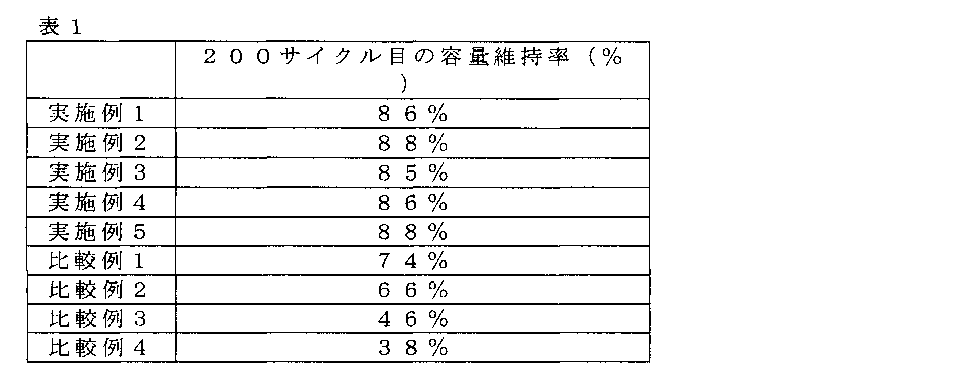
- the capacity retention rates at the 200th cycle of the lithium secondary batteries of the example and the comparative example are shown in Table 1 and FIG.
- the capacity retention rate indicates the ratio of the 200th discharge capacity to the discharge capacity of the first cycle.
- the batteries of Examples 1 to 5 have a capacity retention ratio of at least 85% after 200 cycles, while the batteries of Comparative Examples 1 to 4 have capacity retention after 200 cycles.
- the rate is below 74%.
- Embodiments of the present invention can also be expressed as shown in the following appendices.
- Lithium doping and de-doping methods characterized in that the lithium is doped in the following current value range (A) and in the following doping amount range (B); Current value range (A); a relationship between a voltage V of the negative electrode with respect to the lithium reference electrode and dQ / dV which is a ratio of the change amount dQ of lithium dedoping amount Q of the negative electrode to the change amount dV of the voltage V In the V-dQ / dV curve that represents, the range of current values at which the doping amount at which only one peak appears below 1 V is maximum, Doping amount range (B): a doping amount range in which only one peak appears at 1 V or less on the V-dQ / dV curve.
- the silicon oxide is SiO
- the current density in the current value range (A) is more than 0 and 0.12 A / cm 2 or less
- V ⁇ represents a relationship between a voltage V of the negative electrode with respect to the lithium reference electrode after the doping and dQ / dV which is a ratio of a change amount dQ of the lithium dedoping amount Q of the negative electrode to a change amount dV of the voltage V
- the silicon oxide is SiO
- the current density of the current value is greater than 0 and 0.12 A / cm 2 or less
Abstract
Description
活物質としてケイ素酸化物を含むリチウム二次電池用の負極に作製されてから初めてリチウムをドープ及び脱ドープする方法であって、
下記電流値範囲(A)内で、かつ下記ドープ量範囲(B)内で、前記リチウムをドープすることを特徴とするリチウムのドープ及び脱ドープ方法である。
ドープ量範囲(B);前記V-dQ/dV曲線上において、1V以下にピークが一つのみ現れるドープ量の範囲。
活物質としてケイ素酸化物を含むリチウム二次電池用の負極に作製されてから初めてリチウムをドープ及び脱ドープする方法であって、
該ドープ後の前記負極のリチウム基準極に対する電圧Vと、前記電圧Vの変化量dVに対する前記負極のリチウム脱ドープ量Qの変化量dQの割合であるdQ/dVと、の関係を表すV-dQ/dV曲線上において、1V以下にピークが一つのみ現れるドープ量で、かつ、該ドープ量が最大となる電流値で、
前記リチウムをドープすることを特徴とするリチウムのドープ及び脱ドープ方法である。
(1)活物質としてケイ素酸化物を含む負極活物質層を形成する工程と、
(2)前記負極活物質層に、リチウムをドープ及び脱ドープする工程と、
を含み、
前記工程(2)における前記ドープが、下記電流値範囲(A)内で、かつ下記ドープ量範囲(B)内で、行われることを特徴とするリチウム二次電池用負極の製造方法である。
ドープ量範囲(B);前記V-dQ/dV曲線上において、1V以下にピークが一つのみ現れるドープ量の範囲。
(1)活物質としてケイ素酸化物を含む負極活物質層を形成する工程と、
(2)前記負極活物質層に、リチウムをドープ及び脱ドープする工程と、
を含み、
前記工程(2)における前記ドープが、該ドープ後の前記負極活物質層のリチウム基準極に対する電圧Vと、前記電圧Vの変化量dVに対する前記負極活物質のリチウム脱ドープ量Qの変化量dQの割合であるdQ/dVと、の関係を表すV-dQ/dV曲線上において、1V以下にピークが一つのみ現れるドープ量で、かつ、該ドープ量が最大となる電流値で、行われるリチウム二次電池用負極の製造方法である。
活物質としてケイ素酸化物を含むリチウム二次電池用の負極に作製されてから初めてリチウムをドープ及び脱ドープする方法であって、
下記電流値範囲(A)内の電流で、かつ下記ドープ量範囲(B)内のドープ量で実施されることを特徴とするリチウムのドープ及び脱ドープ方法。
活物質としてケイ素酸化物を含むリチウム二次電池用の負極に作製されてから初めてリチウムをドープ及び脱ドープする方法であって、
該ドープ後の前記負極のリチウム基準極に対する電圧Vと、前記電圧Vの変化量dVに対する前記負極のリチウム脱ドープ量Qの変化量dQの割合であるdQ/dVと、の関係を表すV-dQ/dV曲線上において、1V以下にピークが一つのみ現れるドープ量で、かつ、該ドープ量が最大となる電流値で、
前記リチウムをドープすることを特徴とするリチウムのドープ及び脱ドープ方法である。
本実施形態のリチウム二次電池は、本実施形態のリチウムのドープ及び脱ドープ方法を施された負極を備える。負極は、ケイ素酸化物を含む負極活物質を有する。また、負極は、負極活物質が負極集電体に配置されて形成される。負極活物質は、負極結着材によって負極集電体上に結着されることができる。
正極は、正極活物質が正極集電体に配置されて形成される。正極活物質は、正極結着材によって正極集電体上に結着されることができる。
電解液の材料としては、金属リチウムの酸化還元電位で安定であれば特に限定されるものではなく、公知の非水電解液を採用することができる。
セパレータとしては、特に限定されるものではなく、公知のものを採用することができる。セパレータとして、例えば、ポリプロピレン、ポリエチレン等の多孔質フィルムや不織布を用いることができる。
本実施形態に係る二次電池は、正極および負極が対向配置された電極素子と、電解液とが外装体に内包された構成とすることができる。二次電池の形状は、円筒型、扁平捲回角型、積層角型、コイン型、扁平捲回ラミネート型および積層ラミネート型のいずれも採用できる。
(2)前記負極活物質層に、リチウムをドープ及び脱ドープする工程と、を含み、
前記工程(2)における前記ドープが、下記電流値範囲(A)内で、かつ下記ドープ量範囲(B)内で、行われることを特徴とするリチウム二次電池用負極の製造方法;
電流値範囲(A);前記負極活物質層のリチウム基準極に対する電圧Vと、前記電圧Vの変化量dVに対する前記負極活物質層のリチウム脱ドープ量Qの変化量dQの割合であるdQ/dVと、の関係を表すV-dQ/dV曲線上において、1V以下にピークが一つのみ現れるドープ量が最大となる電流値の範囲、
ドープ量範囲(B);前記V-dQ/dV曲線上において、1V以下にピークが一つのみ現れるドープ量の範囲。
(2)前記負極活物質層に、リチウムをドープ及び脱ドープする工程と、
を含み、
前記工程(2)における前記ドープが、該ドープ後の前記負極活物質層のリチウム基準極に対する電圧Vと、前記電圧Vの変化量dVに対する前記負極活物質のリチウム脱ドープ量Qの変化量dQの割合であるdQ/dVと、の関係を表すV-dQ/dV曲線上において、1V以下にピークが一つのみ現れるドープ量で、かつ、該ドープ量が最大となる電流値で、行われるリチウム二次電池用負極の製造方法。
<負極>
高純度化学社製の一酸化ケイ素(平均粒子直径D50=25μm)と、カーボンブラック(三菱化学社製、#3030B)と、ポリアミック酸(宇部興産社製、商品名;U-ワニスA)とを、それぞれ、83:2:15の質量比で計量し、それらをn-メチルピロリドン(NMP)とホモジナイザーを用いて混合し、負極スラリーを調製した。NMPと固形分の質量比は、57:43とした。負極スラリーを厚さ10μmの銅箔に、ドクターブレードを用いて塗布した。120度Cで7分間加熱し、NMPを乾燥させ負極とした。負極は複数枚作製した。その後、負極を窒素雰囲気下にて、電気炉を用いて350℃で30分間加熱した。
日亜化学製のコバルト酸リチウムと、カーボンブラック(三菱化学社製、#3030B)と、ポリフッ化ビニリデン(クレハ社製、#2400)とを、それぞれ、95:2:3の質量比で計量し、それらをNMPと混合し、正極スラリーを調製した。NMPと固形分の質量比は52:48とした。正極スラリーを厚さ15μmのアルミニウム箔に、ドクターブレードを用いて塗布後、120度Cで5分間加熱し乾燥した。正極を複数枚作製した。
得られた負極と対極に金属リチウムとを用いたハーフセルを複数作製した。電解液には、1.0mol/lのLiPF6電解質塩を含むエチレンカーボネートとジエチルカーボネートとの7:3(体積比)混合溶媒を用いた。
上述の正極及び負極にそれぞれアルミ端子及びニッケル端子を溶接した。これらを、セパレータを介して重ね合わせて電極素子を作製した。正極は、負極中に含まれるケイ素酸化物の単位重量当たりに2650mAh/gのリチウムをドープできるリチウムを含有する。
<電池内での負極へのリチウムドープ>
作製したリチウム二次電池を、電解液を注入してから18時間後に、負極単位面積当たりの電流密度を0.02mA/cm2にして、負極へのリチウムドープを行った。負極中に含まれるケイ素酸化物の単位重量当たりのリチウムドープ量は2300mAh/gとした。
その後、3.0~4.2Vの範囲で充放電サイクル試験を行った。
電池内での負極へのリチウムドープにおける負極単位面積当たりの電流密度をそれぞれ、0.03、0.06、0.09、0.12mA/cm2とした以外は、実施例1と同様に充放電サイクル試験を行った。
電池内での負極へのリチウムドープにおける負極単位面積当たりの電流密度をそれぞれ、0.15、0.18、0.21、0.24mA/cm2とした以外は、実施例1と同様に充放電サイクル試験を行った。
活物質としてケイ素酸化物を含むリチウム二次電池用の負極に作製されてから初めてリチウムをドープ及び脱ドープする方法であって、
下記電流値範囲(A)内で、かつ下記ドープ量範囲(B)内で、前記リチウムをドープすることを特徴とするリチウムのドープ及び脱ドープ方法;
電流値範囲(A);前記負極のリチウム基準極に対する電圧Vと、前記電圧Vの変化量dVに対する前記負極のリチウム脱ドープ量Qの変化量dQの割合であるdQ/dVと、の関係を表すV-dQ/dV曲線上において、1V以下にピークが一つのみ現れるドープ量が最大となる電流値の範囲、
ドープ量範囲(B);前記V-dQ/dV曲線上において、1V以下にピークが一つのみ現れるドープ量の範囲。
前記ドープ量範囲(B)は、1V以下にピークが一つのみ現れるドープ量の最大値の半分以上、1V以下にピークが一つのみ現れるドープ量の最大値以下である付記1に記載のリチウムのドープ及び脱ドープ方法。
前記ケイ素酸化物がSiOであり、
前記電流値範囲(A)の電流密度が0より大きく0.12A/cm2以下であり、
前記ドープ量範囲(B)が約2300mAh/g以下である付記1又は2に記載のリチウムのドープ及び脱ドープ方法。
活物質としてケイ素酸化物を含むリチウム二次電池用の負極に作製されてから初めてリチウムをドープ及び脱ドープする方法であって、
該ドープ後の前記負極のリチウム基準極に対する電圧Vと、前記電圧Vの変化量dVに対する前記負極のリチウム脱ドープ量Qの変化量dQの割合であるdQ/dVと、の関係を表すV-dQ/dV曲線上において、1V以下にピークが一つのみ現れるドープ量で、かつ、該ドープ量が最大となる電流値で、
前記リチウムをドープすることを特徴とするリチウムのドープ及び脱ドープ方法。
前記ドープ量は、1V以下にピークが一つのみ現れるドープ量の最大値である付記4に記載のリチウムのドープ及び脱ドープ方法。
前記ケイ素酸化物がSiOであり、
前記電流値の電流密度が0より大きく0.12A/cm2以下であり、
前記ドープ量が約2300mAh/gである付記5に記載のリチウムのドープ及び脱ドープ方法。
脱ドープ時の電流密度が0.2A/cm2以下である付記1乃至6のいずれかに記載のリチウムのドープ及び脱ドープ方法。
前記ピークは前記ケイ素酸化物の酸化還元反応に由来する付記1乃至7のいずれかに記載のリチウムのドープ及び脱ドープ方法。
付記1乃至8のいずれかに記載の方法でリチウムがドープ及び脱ドープされたリチウム二次電池用の負極。
付記9に記載の負極を有するリチウム二次電池。
Claims (15)
- (1)活物質としてケイ素酸化物を含む負極活物質層を形成する工程と、
(2)前記負極活物質層に、リチウムをドープ及び脱ドープする工程と、
を含み、
前記工程(2)における前記ドープが、下記電流値範囲(A)内で、かつ下記ドープ量範囲(B)内で、行われることを特徴とするリチウム二次電池用負極の製造方法;
電流値範囲(A);前記負極活物質層のリチウム基準極に対する電圧Vと、前記電圧Vの変化量dVに対する前記負極活物質層のリチウム脱ドープ量Qの変化量dQの割合であるdQ/dVと、の関係を表すV-dQ/dV曲線上において、1V以下にピークが一つのみ現れるドープ量が最大となる電流値の範囲、
ドープ量範囲(B);前記V-dQ/dV曲線上において、1V以下にピークが一つのみ現れるドープ量の範囲。 - 前記ドープ量範囲(B)は、1V以下にピークが一つのみ現れるドープ量の最大値の半分以上、1V以下にピークが一つのみ現れるドープ量の最大値以下である請求項1に記載のリチウム二次電池用負極の製造方法。
- 前記ケイ素酸化物がSiOであり、
前記電流値範囲(A)の電流密度が0より大きく0.12A/cm2以下であり、
前記ドープ量範囲(B)が約2300mAh/g以下である請求項1又は2に記載のリチウム二次電池用負極の製造方法。 - (1)活物質としてケイ素酸化物を含む負極活物質層を形成する工程と、
(2)前記負極活物質層に、リチウムをドープ及び脱ドープする工程と、
を含み、
前記工程(2)における前記ドープが、該ドープ後の前記負極活物質層のリチウム基準極に対する電圧Vと、前記電圧Vの変化量dVに対する前記負極活物質のリチウム脱ドープ量Qの変化量dQの割合であるdQ/dVと、の関係を表すV-dQ/dV曲線上において、1V以下にピークが一つのみ現れるドープ量で、かつ、該ドープ量が最大となる電流値で、行われるリチウム二次電池用負極の製造方法。 - 前記ドープ量は、1V以下にピークが一つのみ現れるドープ量の最大値である請求項4に記載のリチウム二次電池用負極の製造方法。
- 前記ケイ素酸化物がSiOであり、
前記電流値の電流密度が0より大きく0.12A/cm2以下であり、
前記ドープ量が約2300mAh/gである請求項5に記載のリチウム二次電池用負極の製造方法。 - 前記工程(2)における前記脱ドープ時の電流密度が0.2A/cm2以下である請求項1乃至6のいずれかに記載のリチウム二次電池用負極の製造方法。
- 前記ピークは前記ケイ素酸化物の酸化還元反応に由来する請求項1乃至7のいずれかに記載のリチウム二次電池用負極の製造方法。
- 請求項1乃至8のいずれかに記載の製造方法で得られたリチウム二次電池用負極を有するリチウム二次電池。
- 活物質としてケイ素酸化物を含むリチウム二次電池用の負極に作製されてから初めてリチウムをドープ及び脱ドープする方法であって、
下記電流値範囲(A)内で、かつ下記ドープ量範囲(B)内で、前記リチウムをドープすることを特徴とするリチウムのドープ及び脱ドープ方法;
電流値範囲(A);前記負極のリチウム基準極に対する電圧Vと、前記電圧Vの変化量dVに対する前記負極のリチウム脱ドープ量Qの変化量dQの割合であるdQ/dVと、の関係を表すV-dQ/dV曲線上において、1V以下にピークが一つのみ現れるドープ量が最大となる電流値の範囲、
ドープ量範囲(B);前記V-dQ/dV曲線上において、1V以下にピークが一つのみ現れるドープ量の範囲。 - 前記ドープ量範囲(B)は、1V以下にピークが一つのみ現れるドープ量の最大値の半分以上、1V以下にピークが一つのみ現れるドープ量の最大値以下である請求項10に記載のリチウムのドープ及び脱ドープ方法。
- 活物質としてケイ素酸化物を含むリチウム二次電池用の負極に作製されてから初めてリチウムをドープ及び脱ドープする方法であって、
該ドープ後の前記負極のリチウム基準極に対する電圧Vと、前記電圧Vの変化量dVに対する前記負極のリチウム脱ドープ量Qの変化量dQの割合であるdQ/dVと、の関係を表すV-dQ/dV曲線上において、1V以下にピークが一つのみ現れるドープ量で、かつ、該ドープ量が最大となる電流値で、
前記リチウムをドープすることを特徴とするリチウムのドープ及び脱ドープ方法。 - 前記ドープ量は、1V以下にピークが一つのみ現れるドープ量の最大値である請求項12に記載のリチウムのドープ及び脱ドープ方法。
- 脱ドープ時の電流密度が0.2A/cm2以下である請求項10乃至13のいずれかに記載のリチウムのドープ及び脱ドープ方法。
- 請求項10乃至14のいずれかに記載の方法でリチウムがドープ及び脱ドープされたリチウム二次電池用の負極。
Priority Applications (3)
| Application Number | Priority Date | Filing Date | Title |
|---|---|---|---|
| US14/114,948 US9123928B2 (en) | 2011-05-27 | 2012-04-06 | Method for doping and dedoping lithium into and from negative electrode and method for producing negative electrode for lithium secondary battery |
| JP2013517917A JP5975024B2 (ja) | 2011-05-27 | 2012-04-06 | 負極にリチウムをドープ及び脱ドープする方法及びリチウム二次電池用負極の製造方法 |
| CN201280025943.9A CN103563132B (zh) | 2011-05-27 | 2012-04-06 | 在负极中掺杂和脱掺杂锂的方法以及制造锂二次电池用负极的方法 |
Applications Claiming Priority (2)
| Application Number | Priority Date | Filing Date | Title |
|---|---|---|---|
| JP2011-119232 | 2011-05-27 | ||
| JP2011119232 | 2011-05-27 |
Publications (1)
| Publication Number | Publication Date |
|---|---|
| WO2012165049A1 true WO2012165049A1 (ja) | 2012-12-06 |
Family
ID=47258914
Family Applications (1)
| Application Number | Title | Priority Date | Filing Date |
|---|---|---|---|
| PCT/JP2012/059540 WO2012165049A1 (ja) | 2011-05-27 | 2012-04-06 | 負極にリチウムをドープ及び脱ドープする方法及びリチウム二次電池用負極の製造方法 |
Country Status (4)
| Country | Link |
|---|---|
| US (1) | US9123928B2 (ja) |
| JP (1) | JP5975024B2 (ja) |
| CN (1) | CN103563132B (ja) |
| WO (1) | WO2012165049A1 (ja) |
Cited By (6)
| Publication number | Priority date | Publication date | Assignee | Title |
|---|---|---|---|---|
| CN103698714A (zh) * | 2014-01-02 | 2014-04-02 | 清华大学 | 电池容量衰减机理辨识方法及系统 |
| US20140099558A1 (en) * | 2012-10-09 | 2014-04-10 | Semiconductor Energy Laboratory Co., Ltd. | Power storage device |
| WO2014199554A1 (ja) * | 2013-06-14 | 2014-12-18 | 信越化学工業株式会社 | 珪素含有材料、非水電解質二次電池用負極及びその製造方法並びに非水電解質二次電池及びその製造方法 |
| JP2015111547A (ja) * | 2013-10-29 | 2015-06-18 | 信越化学工業株式会社 | 負極活物質、負極活物質の製造方法、並びに、リチウムイオン二次電池 |
| JP2017188319A (ja) * | 2016-04-06 | 2017-10-12 | 信越化学工業株式会社 | 負極活物質、混合負極活物質材料、及び負極活物質の製造方法 |
| JP2019533878A (ja) * | 2016-09-02 | 2019-11-21 | イーオーセル リミテッド | シリコン:シリコンケイ酸リチウム複合基質にシリコンナノ粒子が埋め込まれた体積変化補償型のシリコン−酸化シリコン−リチウム複合材料、及び反復的な原位置外製造プロセス |
Families Citing this family (6)
| Publication number | Priority date | Publication date | Assignee | Title |
|---|---|---|---|---|
| JP5682955B2 (ja) * | 2010-08-04 | 2015-03-11 | Necエナジーデバイス株式会社 | リチウム二次電池の制御システム、およびリチウム二次電池の状態検出方法 |
| EP3422377B1 (en) * | 2016-02-26 | 2021-06-30 | Musashi Energy Solutions Co., Ltd. | Doping system, and method for manufacturing electrodes, batteries and capacitors |
| KR20190029711A (ko) * | 2016-10-19 | 2019-03-20 | 오사카 티타늄 테크놀로지스 캄파니 리미티드 | 산화규소계 음극재 및 그 제조 방법 |
| CN111183537B (zh) * | 2017-07-18 | 2023-07-18 | 日产自动车株式会社 | 负极活性物质的预掺杂方法、以及电气设备用电极及电气设备的制造方法 |
| US11949091B2 (en) * | 2018-02-28 | 2024-04-02 | Panasonic Intellectual Property Management Co., Ltd. | Charging method of non-aqueous electrolyte secondary battery, and charging system of non-aqueous electrolyte secondary battery |
| CN112467116A (zh) * | 2020-11-30 | 2021-03-09 | 湖南中科星城石墨有限公司 | 石墨包覆材料及其制备方法、电池负极 |
Citations (4)
| Publication number | Priority date | Publication date | Assignee | Title |
|---|---|---|---|---|
| JP2008177346A (ja) * | 2007-01-18 | 2008-07-31 | Sanyo Electric Co Ltd | エネルギー貯蔵デバイス |
| JP2009076372A (ja) * | 2007-09-21 | 2009-04-09 | Shin Etsu Chem Co Ltd | 非水系二次電池 |
| JP2009076373A (ja) * | 2007-09-21 | 2009-04-09 | Shin Etsu Chem Co Ltd | 非水系二次電池 |
| WO2010071166A1 (ja) * | 2008-12-19 | 2010-06-24 | Necトーキン株式会社 | 非水電解液二次電池用負極、それを用いた非水電解液二次電池、および非水電解液二次電池用負極の製造方法 |
Family Cites Families (6)
| Publication number | Priority date | Publication date | Assignee | Title |
|---|---|---|---|---|
| JP3033221B2 (ja) | 1990-03-30 | 2000-04-17 | 株式会社日立製作所 | 電子回路装置 |
| JP2997741B2 (ja) | 1992-07-29 | 2000-01-11 | セイコーインスツルメンツ株式会社 | 非水電解質二次電池及びその製造方法 |
| JP4088993B2 (ja) | 1998-02-13 | 2008-05-21 | 株式会社ジーエス・ユアサコーポレーション | 非水電解質二次電池の放電制御方法 |
| JP3771846B2 (ja) | 2002-01-15 | 2006-04-26 | 日立マクセル株式会社 | 非水二次電池及びその充電方法 |
| JP4212439B2 (ja) | 2003-09-12 | 2009-01-21 | 三洋電機株式会社 | リチウム二次電池の使用方法 |
| JP4843936B2 (ja) | 2004-01-20 | 2011-12-21 | ソニー株式会社 | 二次電池およびその充放電方法 |
-
2012
- 2012-04-06 JP JP2013517917A patent/JP5975024B2/ja active Active
- 2012-04-06 WO PCT/JP2012/059540 patent/WO2012165049A1/ja active Application Filing
- 2012-04-06 US US14/114,948 patent/US9123928B2/en active Active
- 2012-04-06 CN CN201280025943.9A patent/CN103563132B/zh active Active
Patent Citations (4)
| Publication number | Priority date | Publication date | Assignee | Title |
|---|---|---|---|---|
| JP2008177346A (ja) * | 2007-01-18 | 2008-07-31 | Sanyo Electric Co Ltd | エネルギー貯蔵デバイス |
| JP2009076372A (ja) * | 2007-09-21 | 2009-04-09 | Shin Etsu Chem Co Ltd | 非水系二次電池 |
| JP2009076373A (ja) * | 2007-09-21 | 2009-04-09 | Shin Etsu Chem Co Ltd | 非水系二次電池 |
| WO2010071166A1 (ja) * | 2008-12-19 | 2010-06-24 | Necトーキン株式会社 | 非水電解液二次電池用負極、それを用いた非水電解液二次電池、および非水電解液二次電池用負極の製造方法 |
Cited By (14)
| Publication number | Priority date | Publication date | Assignee | Title |
|---|---|---|---|---|
| US9362564B2 (en) * | 2012-10-09 | 2016-06-07 | Semiconductor Energy Laboratory Co., Ltd. | Power storage device |
| US20140099558A1 (en) * | 2012-10-09 | 2014-04-10 | Semiconductor Energy Laboratory Co., Ltd. | Power storage device |
| US10128541B2 (en) | 2012-10-09 | 2018-11-13 | Semiconductor Energy Laboratory Co., Ltd. | Power storage device |
| US9847555B2 (en) | 2012-10-09 | 2017-12-19 | Semiconductor Energy Laboratory Co., Ltd. | Power storage device |
| US9620820B2 (en) | 2012-10-09 | 2017-04-11 | Semiconductor Energy Laboratory Co., Ltd. | Power storage device |
| JP2015002036A (ja) * | 2013-06-14 | 2015-01-05 | 信越化学工業株式会社 | 珪素含有材料、非水電解質二次電池用負極及びその製造方法並びに非水電解質二次電池及びその製造方法 |
| WO2014199554A1 (ja) * | 2013-06-14 | 2014-12-18 | 信越化学工業株式会社 | 珪素含有材料、非水電解質二次電池用負極及びその製造方法並びに非水電解質二次電池及びその製造方法 |
| JP2015111547A (ja) * | 2013-10-29 | 2015-06-18 | 信越化学工業株式会社 | 負極活物質、負極活物質の製造方法、並びに、リチウムイオン二次電池 |
| US9929399B2 (en) | 2013-10-29 | 2018-03-27 | Shin-Etsu Chemical Co., Ltd. | Negative electrode active material, method for producing a negative electrode active material, and lithium ion secondary battery |
| US10283756B2 (en) | 2013-10-29 | 2019-05-07 | Shin-Etsu Chemical Co., Ltd. | Negative electrode active material, method for producing a negative electrode active material, and lithium ion secondary battery |
| CN103698714A (zh) * | 2014-01-02 | 2014-04-02 | 清华大学 | 电池容量衰减机理辨识方法及系统 |
| JP2017188319A (ja) * | 2016-04-06 | 2017-10-12 | 信越化学工業株式会社 | 負極活物質、混合負極活物質材料、及び負極活物質の製造方法 |
| JP7019284B2 (ja) | 2016-04-06 | 2022-02-15 | 信越化学工業株式会社 | 負極活物質、混合負極活物質材料、及び負極活物質の製造方法 |
| JP2019533878A (ja) * | 2016-09-02 | 2019-11-21 | イーオーセル リミテッド | シリコン:シリコンケイ酸リチウム複合基質にシリコンナノ粒子が埋め込まれた体積変化補償型のシリコン−酸化シリコン−リチウム複合材料、及び反復的な原位置外製造プロセス |
Also Published As
| Publication number | Publication date |
|---|---|
| JP5975024B2 (ja) | 2016-08-23 |
| JPWO2012165049A1 (ja) | 2015-02-23 |
| US20140076729A1 (en) | 2014-03-20 |
| CN103563132B (zh) | 2016-03-23 |
| CN103563132A (zh) | 2014-02-05 |
| US9123928B2 (en) | 2015-09-01 |
Similar Documents
| Publication | Publication Date | Title |
|---|---|---|
| US10991946B2 (en) | Polymerization process for forming polymeric ultrathin conformal coatings on electrode materials | |
| JP5975024B2 (ja) | 負極にリチウムをドープ及び脱ドープする方法及びリチウム二次電池用負極の製造方法 | |
| JP5348706B2 (ja) | 非水電解液二次電池用負極、それを用いた非水電解液二次電池、および非水電解液二次電池用負極の製造方法 | |
| JP6314831B2 (ja) | 負極活物質およびその製造方法、並びにリチウム二次電池 | |
| US20160276671A1 (en) | Negative electrode active material and method for producing the same | |
| JP6056845B2 (ja) | リチウム二次電池用負極の製造方法 | |
| CN102110853A (zh) | 锂离子二次电池、其负极、电动工具、电动车和能量储存系统 | |
| JP2017022120A (ja) | リチウムイオン二次電池 | |
| JP6179404B2 (ja) | 二次電池の製造方法 | |
| WO2015015883A1 (ja) | リチウム二次電池及びリチウム二次電池用電解液 | |
| JP2016186921A (ja) | リチウムイオン二次電池 | |
| Park et al. | Polyimide/carbon black composite nanocoating layers as a facile surface modification strategy for high-voltage lithium ion cathode materials | |
| CN107949935A (zh) | 锂离子二次电池 | |
| WO2016031085A1 (en) | Anode material for lithium ion battery | |
| JP2012252951A (ja) | 非水電解質二次電池 | |
| JP6927303B2 (ja) | リチウムイオン二次電池 | |
| JP6992362B2 (ja) | リチウムイオン二次電池 | |
| JPWO2012029645A1 (ja) | 二次電池およびそれに用いる二次電池用電解液 | |
| JP5573875B2 (ja) | 非水電解質溶液およびリチウムイオン二次電池 | |
| JP2022547282A (ja) | 電池システム、その使用方法、およびそれを含む電池パック | |
| JP2017182946A (ja) | リチウム二次電池用電解液およびこれを備えるリチウム二次電池 | |
| JP2015125965A (ja) | 非水電解液二次電池 |
Legal Events
| Date | Code | Title | Description |
|---|---|---|---|
| WWE | Wipo information: entry into national phase |
Ref document number: 201280025943.9 Country of ref document: CN |
|
| 121 | Ep: the epo has been informed by wipo that ep was designated in this application |
Ref document number: 12793647 Country of ref document: EP Kind code of ref document: A1 |
|
| WWE | Wipo information: entry into national phase |
Ref document number: 14114948 Country of ref document: US |
|
| ENP | Entry into the national phase |
Ref document number: 2013517917 Country of ref document: JP Kind code of ref document: A |
|
| NENP | Non-entry into the national phase |
Ref country code: DE |
|
| 122 | Ep: pct application non-entry in european phase |
Ref document number: 12793647 Country of ref document: EP Kind code of ref document: A1 |