WO2012147644A1 - Réacteur, matériau composite, cœur de réacteur, convertisseur et dispositif de conversion de l'énergie - Google Patents
Réacteur, matériau composite, cœur de réacteur, convertisseur et dispositif de conversion de l'énergie Download PDFInfo
- Publication number
- WO2012147644A1 WO2012147644A1 PCT/JP2012/060693 JP2012060693W WO2012147644A1 WO 2012147644 A1 WO2012147644 A1 WO 2012147644A1 JP 2012060693 W JP2012060693 W JP 2012060693W WO 2012147644 A1 WO2012147644 A1 WO 2012147644A1
- Authority
- WO
- WIPO (PCT)
- Prior art keywords
- composite material
- reactor
- coil
- magnetic
- core portion
- Prior art date
Links
Images


Classifications
-
- H—ELECTRICITY
- H01—ELECTRIC ELEMENTS
- H01F—MAGNETS; INDUCTANCES; TRANSFORMERS; SELECTION OF MATERIALS FOR THEIR MAGNETIC PROPERTIES
- H01F27/00—Details of transformers or inductances, in general
- H01F27/24—Magnetic cores
- H01F27/255—Magnetic cores made from particles
-
- H—ELECTRICITY
- H01—ELECTRIC ELEMENTS
- H01F—MAGNETS; INDUCTANCES; TRANSFORMERS; SELECTION OF MATERIALS FOR THEIR MAGNETIC PROPERTIES
- H01F1/00—Magnets or magnetic bodies characterised by the magnetic materials therefor; Selection of materials for their magnetic properties
- H01F1/01—Magnets or magnetic bodies characterised by the magnetic materials therefor; Selection of materials for their magnetic properties of inorganic materials
- H01F1/03—Magnets or magnetic bodies characterised by the magnetic materials therefor; Selection of materials for their magnetic properties of inorganic materials characterised by their coercivity
- H01F1/12—Magnets or magnetic bodies characterised by the magnetic materials therefor; Selection of materials for their magnetic properties of inorganic materials characterised by their coercivity of soft-magnetic materials
- H01F1/14—Magnets or magnetic bodies characterised by the magnetic materials therefor; Selection of materials for their magnetic properties of inorganic materials characterised by their coercivity of soft-magnetic materials metals or alloys
- H01F1/20—Magnets or magnetic bodies characterised by the magnetic materials therefor; Selection of materials for their magnetic properties of inorganic materials characterised by their coercivity of soft-magnetic materials metals or alloys in the form of particles, e.g. powder
- H01F1/22—Magnets or magnetic bodies characterised by the magnetic materials therefor; Selection of materials for their magnetic properties of inorganic materials characterised by their coercivity of soft-magnetic materials metals or alloys in the form of particles, e.g. powder pressed, sintered, or bound together
- H01F1/24—Magnets or magnetic bodies characterised by the magnetic materials therefor; Selection of materials for their magnetic properties of inorganic materials characterised by their coercivity of soft-magnetic materials metals or alloys in the form of particles, e.g. powder pressed, sintered, or bound together the particles being insulated
- H01F1/26—Magnets or magnetic bodies characterised by the magnetic materials therefor; Selection of materials for their magnetic properties of inorganic materials characterised by their coercivity of soft-magnetic materials metals or alloys in the form of particles, e.g. powder pressed, sintered, or bound together the particles being insulated by macromolecular organic substances
-
- H—ELECTRICITY
- H01—ELECTRIC ELEMENTS
- H01F—MAGNETS; INDUCTANCES; TRANSFORMERS; SELECTION OF MATERIALS FOR THEIR MAGNETIC PROPERTIES
- H01F27/00—Details of transformers or inductances, in general
- H01F27/02—Casings
- H01F27/022—Encapsulation
-
- H—ELECTRICITY
- H01—ELECTRIC ELEMENTS
- H01F—MAGNETS; INDUCTANCES; TRANSFORMERS; SELECTION OF MATERIALS FOR THEIR MAGNETIC PROPERTIES
- H01F37/00—Fixed inductances not covered by group H01F17/00
-
- H—ELECTRICITY
- H02—GENERATION; CONVERSION OR DISTRIBUTION OF ELECTRIC POWER
- H02M—APPARATUS FOR CONVERSION BETWEEN AC AND AC, BETWEEN AC AND DC, OR BETWEEN DC AND DC, AND FOR USE WITH MAINS OR SIMILAR POWER SUPPLY SYSTEMS; CONVERSION OF DC OR AC INPUT POWER INTO SURGE OUTPUT POWER; CONTROL OR REGULATION THEREOF
- H02M7/00—Conversion of ac power input into dc power output; Conversion of dc power input into ac power output
- H02M7/42—Conversion of dc power input into ac power output without possibility of reversal
- H02M7/44—Conversion of dc power input into ac power output without possibility of reversal by static converters
- H02M7/48—Conversion of dc power input into ac power output without possibility of reversal by static converters using discharge tubes with control electrode or semiconductor devices with control electrode
- H02M7/53—Conversion of dc power input into ac power output without possibility of reversal by static converters using discharge tubes with control electrode or semiconductor devices with control electrode using devices of a triode or transistor type requiring continuous application of a control signal
- H02M7/537—Conversion of dc power input into ac power output without possibility of reversal by static converters using discharge tubes with control electrode or semiconductor devices with control electrode using devices of a triode or transistor type requiring continuous application of a control signal using semiconductor devices only, e.g. single switched pulse inverters
-
- H—ELECTRICITY
- H01—ELECTRIC ELEMENTS
- H01F—MAGNETS; INDUCTANCES; TRANSFORMERS; SELECTION OF MATERIALS FOR THEIR MAGNETIC PROPERTIES
- H01F3/00—Cores, Yokes, or armatures
- H01F3/10—Composite arrangements of magnetic circuits
- H01F2003/106—Magnetic circuits using combinations of different magnetic materials
Definitions
- the present invention relates to a composite material suitable for a constituent material of a magnetic part such as a reactor, a reactor core made of the composite material, a reactor including the core, a converter including the reactor, and a power conversion device including the converter. It is about.
- the present invention relates to a reactor having a low loss and a magnetic property that hardly deteriorates, and a composite material that can obtain a reactor having a low loss and a magnetic property that is difficult to deteriorate.
- Patent Document 1 discloses a reactor used as a circuit component of a converter mounted on a vehicle such as a hybrid vehicle.
- Patent Document 1 discloses a composite material composed of a magnetic powder and a resin (binder resin) containing the powder as a constituent material of a magnetic core provided in the reactor. This composite material can be manufactured by filling a molding die having a desired shape with a mixture of a magnetic powder as a raw material and an uncured liquid resin, and then curing the resin.
- loss such as iron loss may be increased, and magnetic characteristics such as relative permeability and inductance may be lower than a set value. Therefore, when a conventional composite material was examined, coarse bubbles of more than 300 ⁇ m were present.
- one of the objects of the present invention is to provide a reactor that has low loss and hardly deteriorates magnetic properties.
- Another object of the present invention is to provide a reactor core that provides a reactor that has low loss and is difficult to deteriorate in magnetic properties.
- the other object of this invention is to provide the composite material suitable for the raw material of the said core for reactors, or the raw material of the magnetic core of the said reactor.
- the present inventor proactively provided a degassing step for sufficiently discharging bubbles (gas) in the composite material in the manufacturing process of the composite material containing the magnetic powder and the resin, thereby increasing the maximum amount of bubbles. It was found that a composite material having a diameter of 300 ⁇ m or less can be obtained. In addition, a composite material with a maximum bubble diameter of 300 ⁇ m or less was used as the material for the magnetic core, and it was found that the reactor including this magnetic core has a magnetic property that is less likely to decrease from the set value and that loss is small. .
- the present invention is based on the above findings.
- the composite material of the present invention is a composite material containing magnetic powder and resin, and the maximum diameter of bubbles in the cross section of the composite material is 300 ⁇ m or less.
- the composite material of the present invention can be produced, for example, by the following production method.
- this production method can be suitably used when the resin is a thermosetting resin or a thermoplastic resin.
- This production method relates to a method of producing a composite material by mixing a magnetic powder and an uncured resin and then curing the resin. The following mixing process, filling process, degassing process, curing It has a process.
- Mixing step A step of producing a mixed fluid by stirring the magnetic powder and the resin while degassing them.
- Tmin (° C) is the temperature at which the viscosity of the above mixed fluid is minimum, and the temperature selected from the range of (Tmin-20) ° C to (Tmin-5) ° C is T 1 (° C), T 2 (C)
- T 1 (° C) is filled in a mold heated to a temperature T 2 (° C.)
- Deaeration step A step of maintaining the mixed fluid filled in the mold at a temperature (Tmin ⁇ 5) ° C. for a predetermined time while deaeration so that the final ultimate vacuum is 1 Pa or less.
- Curing step a step of curing the resin after the predetermined time has elapsed.
- the reactor core of the present invention is made of the above-described composite material of the present invention.
- the reactor of the present invention includes a coil and a magnetic core, and at least a part of the magnetic core is made of the composite material of the present invention. That is, in the reactor of the present invention, at least a part of the magnetic core is composed of a composite material containing magnetic powder and resin, and the maximum bubble diameter in the cross section of the composite material is 300 ⁇ m or less.
- the composite material of the present invention, the core for a reactor of the present invention made of this composite material, and the composite material constituting at least a part of the magnetic core included in the reactor of the present invention have a maximum diameter of 300 ⁇ m or less even if bubbles exist. Therefore, the generation of magnetic flux density due to the presence of bubbles can be suppressed. Therefore, for example, when viewed from the inductance value, the difference between the design value and the actual value is small, and a decrease from the design value can be sufficiently suppressed.
- a reactor that has low loss and hardly deteriorates in magnetic properties can be manufactured.
- the form in which the maximum diameter of the bubbles in the cross section of the composite material is 200 ⁇ m or less is smaller even if bubbles are present.
- a reactor whose characteristics are less likely to deteriorate can be obtained.
- the reactor including this composite material has a lower loss and less magnetic properties.
- the mixed fluid that is sequentially filled in the mold is kept at a substantially constant temperature because the temperature of the mixed fluid does not easily decrease even when it comes into contact with the mold, and the viscosity is low. Since the state can be maintained, it is easy to discharge bubbles. Then, after filling the mold with the mixed fluid, the mixed fluid is held at a temperature Tmin (° C.) at which the viscosity of the resin is lowest and a temperature in the vicinity thereof, so that the resin is in a low viscosity state.
- Tmin ° C.
- the composite material obtained by curing the resin of this mixed fluid has a maximum bubble diameter of 300 ⁇ m or less.
- the composite material of the present invention having a maximum bubble diameter of 300 ⁇ m or less can be produced by separately providing a specific deaeration step.
- the maximum bubble diameter is 300 ⁇ m or less, and the total content of bubbles present is small. For this reason, by using the composite material of the above form, a reactor with lower loss and less magnetic properties is obtained, and the reactor of the above form is less likely to lower magnetic properties with lower loss.
- the maximum bubble diameter is 300 ⁇ m or less, and the total content of the bubbles is very small. Therefore, by using the composite material of the above-described form, a reactor having a lower loss and a magnetic property that is less likely to be deteriorated is obtained, and the reactor of the above-described form is further unlikely to have a lower loss and a magnetic property that is not easily lowered.
- the reactor of the present invention As one form of the reactor of the present invention and the composite material of the present invention, a form in which the volume ratio of the magnetic powder in the composite material is 30% by volume or more and 70% by volume or less can be given.
- the ratio of the magnetic component is sufficiently high, it is easy to improve the magnetic characteristics such as saturation magnetic flux density, and it is easy to mix with the resin and easy to produce a composite material because there is not too much magnetic powder.
- the material of the magnetic core provided in the reactor of the present invention can be partially different.
- positioned inside a coil in a magnetic core is made into the above-mentioned composite material
- positioned outside a coil is made into a material whose relative permeability is higher than the said composite material, Since the leakage magnetic flux from the place arranged outside the coil to the outside can be reduced, the loss accompanying this leakage magnetic flux can be reduced and the magnetic flux generated by the coil can be fully utilized.
- the outer core At least a portion of the magnetic core disposed on the outside of the coil (hereinafter referred to as the outer core) is the above-described composite material, for example, a portion disposed on the inside of the coil (hereinafter referred to as the inner core).
- the entire magnetic core is made of a material having a low relative permeability and the saturation magnetic flux density is uniform, so the cross-sectional area of the inner core can be reduced.
- the said form can achieve size reduction of a reactor.
- winding which comprises a coil can also be shortened by size reduction of an inner core, the said form can aim at the weight reduction of a reactor.
- the resin component is contained and the material has a relatively low relative permeability over the entire magnetic core, for example, a gapless structure can be obtained.
- the said form is excellent in productivity, when comprising a magnetic core with the same material.
- the said form can manufacture the magnetic core from which a magnetic characteristic differs partially by adjusting the material and content of magnetic body powder, etc. easily.
- the coil is housed in the case so that its axis is substantially parallel to the bottom surface of the case, and the magnetic core covers at least a part of the outer periphery of the coil with the composite material.
- the said form is excellent in heat dissipation, since it is easy to transmit the heat of a coil to the bottom face of a case, and can radiate
- the said form WHEREIN By storing the assembly of a coil and a magnetic core in a case, the protection of the said assembly and the external environment can be aimed at.
- the reactor of the above-mentioned form is a composite material in accordance with the above-described manufacturing method, for example, using a molding die as a case in the above-described manufacturing method and storing a coil or a combination of a coil and a part of a magnetic core in this case. It can manufacture by forming.
- This composite material constitutes at least a part of the magnetic core of the reactor.
- a form in which at least a part of the magnetic core described above disposed outside the coil is the composite material, or a form in which substantially all of the magnetic core is the composite material. Easy to manufacture.
- the relative permeability of the composite material of the present invention constituting the magnetic core is preferably 5 or more and 50 or less, more preferably 5 or more and 20 or less, in order to adjust the inductance of the reactor to a predetermined value. preferable.
- the relative magnetic permeability of the composite material is desirably 10 or more and 20 or less.
- the reactor of the present invention can be suitably used as a component part of a converter.
- the converter of the present invention comprises a switching element, a drive circuit that controls the operation of the switching element, and a reactor that smoothes the switching operation, and converts the input voltage by the operation of the switching element.
- the form whose reactor is this invention reactor is mentioned.
- This converter of the present invention can be suitably used as a component part of a power converter.
- the power converter of the present invention includes a converter that converts an input voltage and an inverter that is connected to the converter and converts between direct current and alternating current, and drives a load with the power converted by the inverter. And the converter is a converter according to the present invention.
- the converter of the present invention and the power converter of the present invention include the reactor of the present invention that is low in loss and hardly deteriorates in magnetic characteristics, so that it is easy to maintain desired magnetic characteristics with low loss.
- the reactor of the present invention has low loss and hardly deteriorates magnetic characteristics.
- the core for reactor of the present invention and the composite material of the present invention have a maximum bubble diameter of 300 ⁇ m or less, and can contribute to the realization of a reactor with low loss and less magnetic properties.
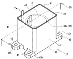
- FIG. 1 is a schematic perspective view of a reactor according to Embodiment 1.
- FIG. FIG. 2 is a cross-sectional view of (A)-(A) in FIG.
- FIG. 2 is a cross-sectional view of (B)-(B) in FIG. 3 is a photomicrograph of a cross section of an outer core part provided in the reactor according to the first embodiment. It is a microscope picture of the cross section of the outer core part with which the reactor of a comparative example is provided.
- 5 is a schematic perspective view of a reactor according to Embodiment 2.
- FIG. It is (B)-(B) sectional drawing of FIG. 4A.
- 5 is a schematic perspective view of a reactor according to Embodiment 3.
- 1 is a schematic configuration diagram schematically showing a power supply system of a hybrid vehicle. It is a schematic circuit diagram which shows an example of this invention power converter device which provides this invention converter.
- a reactor 1A according to Embodiment 1 will be described with reference to FIGS. 1, 2A, and 2B.
- a reactor 1A includes a coil 2w formed by spirally winding a winding 2w, a magnetic core 3 disposed inside and outside the coil 2 to form a closed magnetic circuit, and the coil 2 and the magnetic core 3 It includes a case 4A for storing the union.
- the reactor 1A is usually installed on an installation target such as a cooling base having a cooling mechanism such as a cooling water circulation path, and is used after being cooled by the cooling mechanism.
- case 4A is fixed to the installation target.
- the magnetic core 3 includes an inner core portion 31 disposed inside the coil 2 and an outer core portion 32 provided so as to cover the outer periphery of the coil 2.
- Reactor 1A is characterized in that it is located outside cylindrical coil 2: the outer core portion 32 is made of a composite material, and the maximum bubble diameter in this composite material is 300 ⁇ m or less. It is in.
- the outer core portion 32 is made of a composite material, and the maximum bubble diameter in this composite material is 300 ⁇ m or less. It is in.
- the coil 2 is a cylindrical body formed by spirally winding one continuous winding 2w.
- the winding 2w is preferably a coated wire having an insulating coating made of an insulating material (typically an enamel material such as polyamideimide) on the outer periphery of a conductor made of a conductive material such as copper, aluminum, or an alloy thereof.
- the conductor may have various shapes such as a rectangular wire having a rectangular cross-sectional shape, a round wire having a circular shape, and a deformed wire having a polygonal shape. In particular, if the rectangular wire is edgewise-wound and used as an edgewise coil, it is easy to obtain a coil with a high space factor.
- the coil 2 is an edgewise coil formed by edgewise winding a rectangular wire whose conductor is made of copper and whose cross-sectional shape is a rectangular shape and whose insulating coating is made of enamel.
- End face shape The end surface shape of the coil 2 and the cross-sectional shape in the direction orthogonal to the axial direction are typically circular as shown in FIGS.
- a circular coil is easy to wind even when a rectangular wire is used as a winding, and is excellent in coil manufacturability and is easily made into a small coil.
- the end face shape of the coil 2 is a non-circular shape and has a curved portion, for example, a shape consisting essentially of a curve such as an ellipse, or a shape having a curved portion and a straight portion (for example, For example, a shape obtained by rounding corners of a polygon such as a rectangle, or a racetrack formed by combining a straight line and an arc.
- the coil is housed in the case so that the flat surface formed by the straight portion is parallel to the bottom surface of the case, thereby providing excellent stability and heat dissipation.
- Both ends of the winding 2w forming the coil 2 are appropriately extended from the turn forming portion as shown in FIG. 1, and the conductive portion such as copper or aluminum is exposed to the exposed conductor portion after the insulation coating is peeled off.
- a terminal member (not shown) made of a material is connected.
- An external device (not shown) such as a power source for supplying power is connected to the coil 2 through this terminal member.
- welding such as TIG welding or crimping can be used for the connection between the conductor portion of the winding 2w and the terminal member. It should be noted that the pulling direction of both ends of the winding 2w is an example, and can be changed as appropriate.
- the coil 2 is housed in the case 4A so that the axis of the coil 2 is substantially parallel to the bottom surface 40 of the case 4A.
- the coil 2 is accommodated so that the coil 2 is horizontally long with respect to the case 4A (hereinafter, this arrangement form is referred to as a horizontal form).
- substantially parallel means that both the outer bottom surface 40o and the inner bottom surface 40i are flat surfaces, and the axis of the coil 2 and both surfaces 40o, 40i are parallel, as well as a part of the outer bottom surface 40o and the inner bottom surface 40i. This includes a case where there is a portion that is not configured in a plane and is not parallel to the axis of the coil 2 (for example, the outer bottom surface 40o is configured in a plane and the inner bottom surface 40i is uneven).
- the magnetic core 3 includes a columnar inner core portion 31 inserted into the coil 2, at least one end surface 31e (here, both end surfaces) of the inner core portion 31, and the coil 2
- the outer core 32 is formed so as to cover the outer peripheral surface, and a closed magnetic circuit is formed when the coil 2 is excited.
- the magnetic core 3 is not made of a uniform material, the material is partially different, and the magnetic characteristics are partially different.
- the inner core portion 31 has a higher saturation magnetic flux density than the outer core portion 32
- the outer core portion 32 has a lower relative permeability than the inner core portion 31.
- the inner core portion 31 is a cylindrical body along the inner peripheral shape of the coil 2.
- the length of the inner core portion 31 along the axial direction of the coil 2 (hereinafter simply referred to as the length) is longer than the length of the coil 2 and is inserted and arranged inside the coil 2.
- both end surfaces 31e of the inner core portion 31 and the outer peripheral surface in the vicinity thereof slightly protrude from the end surface of the coil 2.
- the protruding length of the inner core portion 31 can be appropriately selected.
- the protruding lengths protruding from the end faces of the coil 2 in the inner core portion 31 are made equal, but they may be different as in Embodiment 2 described later, or from either one end face of the coil 2 You may adjust the length of an inner core part, and the arrangement position with respect to a coil so that only a protrusion part exists.
- the length of the inner core portion and the length of the coil may be equal, and the length of the inner core portion may be shorter than the length of the coil, but as shown in FIGS. 2A and 4 (B) It is preferable that the length of the core portion 31 is equal to or greater than the length of the coil 2 because the magnetic flux generated by the coil 2 can be sufficiently passed through the inner core portion 31.
- the inner core portion 31 is composed of a compacted body made of a soft magnetic material having a coating such as an insulating coating.
- the green compact is typically formed by molding a soft magnetic powder having an insulating coating made of a silicone resin or the like on the surface, or a mixed powder in which a binder is appropriately mixed in addition to the soft magnetic powder, and then forming the insulating coating. It can be obtained by firing at a temperature lower than the heat resistant temperature.
- the saturation magnetic flux density can be changed. For example, by using soft magnetic powder with a high saturation magnetic flux density, increasing the proportion of soft magnetic material by reducing the amount of binder, or increasing the molding pressure, compacting with high saturation magnetic flux density The body is obtained.
- the soft magnetic powder is an iron group metal such as Fe, Co, Ni, Fe-based alloy containing Fe as a main component, for example, Fe-Si, Fe-Ni, Fe-Al, Fe-Co, Fe-Cr, Fe- Examples thereof include powders made of iron-based materials such as Si-Al, rare earth metal powders, and ferrite powders.
- the iron-based material is easy to obtain a magnetic core having a saturation magnetic flux density higher than that of ferrite.
- the constituent material of the insulating coating formed on the soft magnetic powder include a phosphoric acid compound, a silicon compound, a zirconium compound, an aluminum compound, and a boron compound.
- This insulation coating can effectively reduce eddy current loss, especially when the magnetic particles constituting the soft magnetic powder are made of a metal such as an iron group metal or an Fe group alloy.
- the binder include thermoplastic resins, non-thermoplastic resins, and higher fatty acids. This binder disappears by the above-mentioned baking, or changes to an insulator such as silica.
- the compacted body can be molded relatively easily even in a complicated three-dimensional shape.
- the presence of an insulator such as an insulating film between the magnetic particles insulates the magnetic particles from each other, resulting in an eddy current.
- the loss can be reduced, and the above-described loss can be reduced even when high-frequency power is supplied to the coil.
- a well-known thing can be utilized for a compacting body.
- the columnar inner core portion 31 can be obtained by making it an integrated product formed by using a mold having a desired shape, or by fixing a plurality of core pieces with an adhesive or an adhesive tape.
- the inner core portion 31 is a solid body in which no gap material or air gap is interposed.
- the coil 2 and the inner core portion 31 can be brought close to each other, and from this point, the reactor 1A can also be reduced in size. .
- the magnetic core 3 may have a form in which a compact material or a material having a lower relative permeability than a composite material described later, typically a gap material made of a nonmagnetic material such as an alumina plate, or an air gap is interposed. .
- a gap material having a relative permeability greater than 1 may be interposed.
- the constituent material of the gap material include a material in which a magnetic powder such as iron or Fe—Si is dispersed in a nonmagnetic material (for example, a resin such as unsaturated polyester).
- a gap material having a relative permeability greater than 1 that is, a gap material having magnetism, it is easy to adjust the inductance of the reactor.
- the relative permeability of the gap material is preferably more than 1 and 5 or less, and more preferably 1.1 or more and 1.4 or less.
- the outer core portion 32 covers substantially all of the both end surfaces and the outer peripheral surface of the coil 2, the both end surfaces 31e of the inner core portion 31 and the outer peripheral surface in the vicinity thereof, and the inner peripheral surface of the case 4A. And the shape along the space formed by the outer peripheral surface of the assembly of the coil 2 housed in the case 4A and the inner core portion 31.
- the magnetic core 3 forms a closed magnetic path by providing a part of the outer core part 32 so as to be connected to both end faces 31e of the inner core part 31.
- the entire outer core portion 32 is formed of a composite material containing a magnetic powder and a resin.
- the maximum bubble diameter is 300 ⁇ m or less.
- a composite material containing magnetic powder and resin can be typically produced by injection molding or cast molding.
- injection molding normally, magnetic powder and fluid resin (liquid resin) are mixed, and this mixed fluid is poured into a mold (including case 4A) under a predetermined pressure. Then, the composite material is obtained by curing the resin.
- cast molding a composite material is obtained by obtaining a mixed fluid similar to that of injection molding, and then injecting the mixed fluid into a molding die without applying pressure and molding and curing.
- a composite material having a maximum bubble diameter of 300 ⁇ m or less can be obtained by preparing a mixed fluid under specific conditions described later and filling it into a mold, and through a specific degassing step.
- the case 4 is used as a mold. In this case, even a complex shaped composite material can be easily molded.
- a plurality of molded bodies having a desired shape can be produced and combined to form a magnetic core having a desired shape.
- the cross section of the composite material may be either a cross section cut along the axial direction of the coil 2 or a cross section cut along a direction orthogonal to the axial direction.
- the maximum diameter of bubbles is a plurality of cross-sections (for example, 10 cross-sections) of a fixed-size visual field (e.g., 5 mm x 7 mm) for the composite material, and the equivalent circle diameter of the outline from the outline of the bubbles present in each cross-section (The diameter when the shape of the bubble that can be confirmed in each cross section is converted into a circle of the same area) is calculated, and when this equivalent circle diameter is the diameter of the bubble, the maximum value of the diameter of the bubble in the plurality of cross sections And
- By observing the cross section with an optical microscope or the like (about 10 to 50 times) and processing the observed image with a commercially available image processing apparatus it is possible to easily extract the outline of bubbles and calculate the equivalent circle diameter.
- the bubble diameter for example, 10 cross-sections
- the equivalent circle diameter
- the magnetic flux lines due to the bubbles bypass the magnetic flux lines locally in the composite material, resulting in a decrease in magnetic properties.
- the number of bubbles is preferably as small as possible. That is, the bubble content itself is preferably as small as possible.
- the total area ratio of bubbles in the cross section of the composite material is preferably 1% or less.
- the total area ratio of the bubbles in the cross section of the composite material is one spherical bubble having a diameter of 300 ⁇ m, and is less than the area ratio of the cross-sectional circle passing through the diameter of the bubbles, specifically 0.2% or less. preferable.
- the area of the cross-sectional circle passing through the diameter of a spherical bubble having a diameter of 300 ⁇ m (0.3 mm) is (square of radius 0.15 mm) ⁇ ⁇ 0.07 mm 2 .
- the total area ratio is the ratio of the total area of bubbles to the cross-sectional area of the 5 mm ⁇ 7 mm field of view described above.
- the visual field only needs to satisfy an area of 35 ⁇ 5 mm 2, and examples of the shape include a rectangular shape and a square shape.
- the magnetic substance powder in the composite material constituting the outer core part 32 may have the same composition as or a different composition from the soft magnetic powder of the compacting body constituting the inner core part 31 described above. Since the composite material constituting the outer core portion 32 contains a relatively large amount of a resin that is a nonmagnetic material, the magnetic powder is a soft magnetic powder having the same composition as the green compact forming the inner core portion 31. Even if it exists, a saturation magnetic flux density is lower than the said compacting body, and a relative magnetic permeability also becomes low.
- the magnetic substance powder constituting the outer core portion 32 is preferably made of an iron-based material such as pure iron powder or Fe-based alloy powder.
- the magnetic powder may be a mixture of a plurality of types of powders having different materials.
- the magnetic powder is made of a metal material, eddy current loss can be reduced if the surface of each particle constituting the powder is a coating powder having an insulating coating made of phosphate or the like.
- the average particle diameter of the magnetic powder in the composite material constituting the outer core portion 32 is preferably 1 ⁇ m or more and 1000 ⁇ m or less, and particularly preferably 10 ⁇ m or more and 500 ⁇ m or less.
- the magnetic powder in the composite material constituting the outer core portion 32 and the powder used as the raw material have substantially the same size (maintained).
- the mixed fluid is excellent in fluidity, so that the productivity of the composite material is excellent.
- the magnetic powder may include a plurality of types of powders having different particle sizes.
- the content of the magnetic powder in the composite material constituting the outer core portion 32 is 30% to 70% by volume, further 40% to 65% by volume, especially 40%, when the composite material is 100%. % Or more and 60% by volume or less.
- the magnetic powder is at least 30% by volume, the magnetic component ratio is sufficiently high, so that magnetic properties such as saturation magnetic flux density can be easily improved.
- the magnetic powder is made of a material having a saturation magnetic flux density of about 2T, such as iron or Fe-Si alloy
- the saturation magnetic flux density is 0.6T because the content of the magnetic powder is 30% by volume or more.
- the saturation magnetic flux density can be easily increased to 0.8 T or more by being 40% by volume or more.
- the magnetic substance powder is 70% by volume or less, it becomes easy to mix the magnetic substance powder and the resin at the time of production, and the productivity is excellent.
- the resin that serves as the binder in the composite material that forms the outer core portion 32 typically includes a thermosetting resin such as an epoxy resin, a phenol resin, a silicone resin, a urethane resin, or an unsaturated polyester.
- a thermoplastic resin, a room temperature curable resin, or a low temperature curable resin can be used as a resin serving as a binder.
- the thermoplastic resin include polyphenylene sulfide (PPS) resin, polyimide resin, and fluororesin.
- the composite material As one form of the composite material, a form in which a filler (typically a non-magnetic powder) made of ceramics such as alumina or silica is mixed in addition to a magnetic powder and a resin serving as a binder.
- a filler typically a non-magnetic powder
- ceramics such as alumina or silica
- a resin serving as a binder.
- the content of the filler is preferably 0.3% by mass or more, and more preferably 0.5% by mass or more.
- the filler content is preferably 20% by mass or less, more preferably 15% by mass or less, and particularly preferably 10% by mass or less.
- the outer core part 32 is composed of a composite material of a coating powder and an epoxy resin having the insulating coating on the surface of particles made of an iron-based material (pure iron) having an average particle diameter of 75 ⁇ m or less (composite). Content of pure iron powder in the material: 45% by volume).
- the magnetic powder in the composite material is typically in a form in which the magnetic particles constituting the powder are uniformly dispersed in the composite material.
- the magnetic powder in the composite material is typically in a form in which the magnetic particles constituting the powder are uniformly dispersed in the composite material.
- the bottom surface side of the mold here, the bottom surface 40 side of the case 4A. That is, in the outer core portion 32, when the proportion of the magnetic powder on the bottom surface 40 side of the case 4A is compared with the proportion of the magnetic powder on the opening side facing the bottom surface 40, the form in which the presence ratio on the bottom surface 40 side is large. It can be.
- the outer core portion 32 is not particularly limited as long as a closed magnetic path can be formed.
- the outer core portion 32 is the coil 2 or the inner core. It also functions as a sealing material for the portion 31, and can enhance protection and mechanical protection from the external environment of the coil 2.
- a part of the outer periphery of the coil 2 may not be covered with the composite material constituting the outer core portion 32.
- a possible groove is provided on the bottom surface of the case 4A, and the portion housed in the groove is not covered with the composite material.
- heat dissipation is improved by exposing the region on the opening side farthest from the bottom surface of the case 4A in the coil 2 or increasing the number of contact points with the case 4A.
- the lid In the form in which a part of the coil 2 is exposed, it is preferable to provide a lid that covers the opening of the case. If the lid is made of a conductive material such as metal (may be the same material as the case), the leakage flux from the exposed portion of the coil 2 to the outside can be suppressed, and the lid can also be used as a heat dissipation path.
- a positioning member (not shown) for the coil 2 is separately arranged on the inner bottom surface 40i of the case 4A, and the contact portion with the positioning member in the coil 2 is not covered with the composite material constituting the outer core portion. be able to.
- the material of the positioning member is preferably an insulating material so that the insulating property between the coil 2 and the case 4A can be improved. If the material is excellent in heat dissipation, the heat dissipation can be improved.
- the positioning member and the coil 2 are sealed with a composite material constituting the outer core portion 32, so that the mutual positions are fixed.
- a part of the inner core portion 31 may be not covered with the composite material constituting the outer core portion 32.
- a support member that supports a portion protruding from the end face of the coil 2 in the inner core portion 31 is provided, and the contact portion with the support member in the inner core portion 31 is not covered with the composite material.
- the inner core portion 31 is positioned with respect to the case 4A by the support member, and the coil 2 can be positioned by positioning the inner core portion 31. Furthermore, each position is fixed by being sealed with the composite material constituting the outer core portion 32. Accordingly, when the support member is provided, the positioning member for the coil 2 described above may be omitted.
- This support member may be formed integrally with the case 4A, or may be a separate member made of the composite material or other material.
- the support member is also made of a material having excellent heat dissipation, so that the heat dissipation can be improved. Further, by adjusting the size of the support member and supporting the inner core portion 31 so as to have a gap between the coil 2 and the inner bottom surface 40i of the case 4A, the insulation between the two can be improved. And if it is set as the form which both contact, heat dissipation is improved.
- the inner core portion 31 and the outer core portion 32 are joined by a resin in the composite material constituting the outer core portion 32 without interposing an adhesive.
- the outer core portion 32 is also free of gap material or air gap, and the magnetic core 3 is an integrated product that is integrated without any gap material. Therefore, in the reactor 1A, when the magnetic core 3 is manufactured, the step of joining with an adhesive or the like is unnecessary, and the productivity of the reactor 1A is excellent.
- the inner core portion 31 and the outer core portion 32 can be joined with an adhesive.
- the inner core portion 31, the outer core portion 32, and the gap material can be joined with an adhesive.
- the bonding can be performed in a plurality of bonding steps. When the adhesive is sufficiently small, it is considered that the adhesive does not substantially function as a gap material.
- the inner core portion 31 has a saturation magnetic flux density of 1.6 T or more and 1.2 times or more of the outer core portion 32, a relative magnetic permeability of 100 to 500, and the outer core portion 32 has an inner saturation magnetic flux density of 0.5 T or more.
- the relative magnetic permeability is 10 or more and 100 or less.
- the saturation magnetic flux density of the inner core portion 31 is preferably 1.8 T or more, more preferably 2 T or more, more preferably 1.5 times or more, and more preferably 1.8 times or more of the saturation magnetic flux density of the outer core portion 32, and no upper limit is provided.
- the saturation magnetic flux density of the inner core portion can be further increased.
- the relative permeability of the outer core portion 32 is lower than that of the inner core portion 31, for example, magnetic flux easily passes through the inner core portion 31.
- the magnetic saturation can be suppressed by providing a portion having a low relative magnetic permeability, the magnetic core 3 having a gapless structure can be obtained.
- an insulating member may be interposed between them.
- an insulating tape may be attached to the outer peripheral surface or inner peripheral surface of the coil 2, or the outer peripheral surface or inner peripheral surface of the coil 2 may be covered with insulating paper or an insulating sheet.
- a cylindrical insulator may be disposed outside the inner core portion 31 or outside the coil 2.
- an insulating resin such as a PPS resin, a liquid crystal polymer (LCP), or a polytetrafluoroethylene (PTFE) resin can be suitably used.
- this insulator is a split piece that can be divided in the radial direction of the inner core portion 31 or the coil 2, it can be easily disposed outside the inner core portion 31 or outside the coil 2. If the cylindrical body disposed outside the inner core portion 31 has an annular flange that protrudes outward from the peripheral edge of both ends, the end surface of the coil 2 can be covered by this flange.
- a form in which the outer peripheral surface and the inner peripheral surface of the coil 2 and the end surface are covered with an insulating resin is used.
- the resin can be used for positioning the inner core portion 31.
- a coil molded body in which the coil 2 and the inner core portion 31 are integrally molded with an insulating resin may be used.
- the integrated body of the coil 2 and the inner core portion 31 can be easily stored in the case 4A.
- the insulating resin can also have a function of holding the shape of the coil 2 and holding the coil 2 in a compressed state rather than its natural length.
- the coil molded body can easily handle the coil 2 and can shorten the length of the coil 2 in the axial direction.
- the thickness of the resin in the coil molded body is, for example, about 1 mm to 10 mm.
- a production method described in JP-A-2009-218293 can be used for the production of the coil molded body.
- the molding include injection molding, transfer molding, and cast molding.
- the insulating resin a thermosetting resin such as an epoxy resin, or a thermoplastic resin such as a PPS resin or LCP can be suitably used.
- Heat dissipation can be improved by using an insulating resin in which a filler made of at least one ceramic selected from silicon nitride, alumina, aluminum nitride, boron nitride, and silicon carbide is used.
- a high voltage may be applied to the lead-out portion of the winding 2 w extended from the turn forming portion as compared with the turn forming portion. Accordingly, at least the contact portion with the magnetic core 3 (outer core portion 32) of the lead-out portion of the winding 2w is covered with the insulating resin, insulating paper, insulating tape (for example, polyimide tape), insulating
- the insulating resin insulating paper, insulating tape (for example, polyimide tape)
- an insulating material such as a film (e.g., polyimide film) is appropriately wound, the insulating material is dip-coated, or an insulating tube (either a heat shrinkable tube or a room temperature shrinkable tube) is disposed, the coil 2 and the magnetic
- the insulation between the core 3 in particular, the outer core portion 32 here
- the outer core portion 32 can be enhanced.
- the case 4A is typically a rectangular parallelepiped box composed of a rectangular plate-shaped bottom surface 40 and a rectangular frame-shaped side wall 41 erected from the bottom surface 40, and the surface facing the bottom surface 40 is open. The thing which was done is mentioned.
- the bottom surface 40 of the case 4A is a surface in contact with the installation target when the reactor 1A is installed on the installation target.
- the bottom surface 40 is shown as being disposed below, it may be disposed laterally (left and right in FIG. 1) or above.
- the case 4A is typically used as a container that houses a combination of the coil 2 and the magnetic core 3 and protects the combination from the external environment such as dust and corrosion or mechanically protects the combination. At the same time, it is used for the heat dissipation path. Therefore, the constituent material of the case 4A is preferably a material having excellent thermal conductivity, preferably a material having higher thermal conductivity than a magnetic powder such as iron, for example, a metal such as aluminum, aluminum alloy, magnesium, magnesium alloy. it can. Since these aluminum, magnesium, and alloys thereof are lightweight, they are also suitable as materials for automobile parts that are desired to be reduced in weight. Further, since these aluminum, magnesium, and alloys thereof are nonmagnetic materials and conductive materials, leakage magnetic fluxes to the outside of the case 4A can be effectively prevented.
- the case 4A is made of an aluminum alloy.
- the bottom surface 40 may have a flat surface on the front and back surfaces (inner bottom surface 40i and outer bottom surface 40o), but as described above, the groove or inner core portion along the outer peripheral shape of the coil 2 may be used. If the support member that supports 31 is provided, heat of the coil 2 and the inner core portion 31 can be easily transmitted to the case 4A, and heat dissipation can be improved. Further, if the side wall 41 is provided with heat radiating fins or the like, the heat dissipation can be improved.
- the case 4A includes a mounting portion 45 having a bolt hole 45h for fixing the reactor 1A to an installation target with a fixing member such as a bolt as shown in FIG.
- a fixing member such as a bolt
- Such a case 4A can be easily manufactured by casting, cutting, plastic working, or the like.
- the above-described insulating material may be disposed between the coil 2 and the case 4A.
- This insulating material only needs to be present to the extent that the minimum insulation required between the coil 2 and the case 4A can be ensured.
- the insulating material is made of a material having excellent thermal conductivity, the heat dissipation can be further improved.
- an insulating adhesive is used as the insulating material, the coil 2 can be securely fixed to the case 4A and insulation can be ensured.
- the adhesive is excellent in thermal conductivity, for example, an adhesive containing a filler excellent in thermal conductivity and electrical insulation, such as alumina, heat dissipation can be improved.
- the reactor 1A has a horizontal configuration in which the coil 2 is stored horizontally with respect to the case 4A.
- the contact area between the outer peripheral surface of the coil 2 and the inner bottom surface 40i of the case 4A is increased, or the distance from the outer peripheral surface of the coil 2 to the inner bottom surface 40i of the case 4A is short, that is, close to the installation target. It is easy to increase the area. Therefore, the horizontal configuration can efficiently transfer the heat of the coil 2 to the case 4A, and this heat is transferred to the installation target through the outer bottom surface 40o of the case 4A in contact with the installation target. Therefore, the horizontal form is excellent in heat dissipation.
- Reactor 1A having the above-described configuration has applications such as maximum current (DC): about 100A to 1000A, average voltage: about 100V to 1000V, operating frequency: about 5kHz to 100kHz, typically electric It can be suitably used as a component part of an in-vehicle power converter such as an automobile or a hybrid automobile.
- DC maximum current
- the reactor 1A-vehicle part, the reactor 1A it is preferable capacity including the case 4A is 0.2 liters (200cm 3) ⁇ 0.8 liters (800 cm 3) approximately. More specifically, in the case of a coil having a circular end face shape, the inner diameter: 20 mm to 80 mm, the number of turns: 30 to 70, and in the case of a cylindrical inner core, the diameter: 10 mm to 70 mm, height (in the axial direction) Length): 20 mm to 120 mm, one side of the bottom of the rectangular box-shaped case: 30 mm to 100 mm. In this example, it is about 500 cm 3 .
- the reactor 1A including the outer core portion 32 made of a composite material having a maximum bubble diameter of 300 ⁇ m or less can be manufactured as follows.
- a case 4A serving as a molding die, and an assembly of the coil 2 and the inner core portion 31 stored in the case 4A are prepared.
- the insulating material described above may be interposed between the coil 2 and the inner core portion 31.
- Desired magnetic powder and resin, and appropriate non-magnetic powder are prepared, placed in a container, mixed and stirred to produce a mixed fluid.
- this mixing step is performed while degassing.
- Degassing may be evacuation.
- the final ultimate vacuum in the mixing step is preferably about 10 Pa to 1000 Pa. Here, it was set to about 500 Pa.
- the gas (mainly air) in the atmosphere is most easily entrained, and the entrained gas is likely to remain in the composite material as bubbles. Therefore, by mixing while degassing, bubbles in the composite material are small and easy to reduce.
- This mixing step can be easily performed by using a commercially available stirring device having a degassing mechanism capable of degassing the inside of the container.
- the mixing step can be performed at room temperature (about 20 ° C. to 25 ° C.).
- Thermosetting resins and thermoplastic resins generally have a lower viscosity and higher fluidity as the temperature is higher. Therefore, the temperature of the mixed fluid is increased when filling the mixed fluid that has undergone the mixing step into the mold (in this case, case 4A). This temperature is lower than the temperature Tmin at which the viscosity of the mixed fluid is minimized within a range of 5 ° C. to 20 ° C.
- the temperature T 1 is a temperature selected from (Tmin ⁇ 20) ° C. to (Tmin ⁇ 5) ° C.
- the temperature Tmin in the desired mixed fluid is determined by preparing a mixed fluid in which the desired magnetic powder, resin, and appropriate non-magnetic powder are blended at a desired ratio, and examining the relationship between the temperature and viscosity of the mixed fluid in advance. Is required.
- the temperature T 1 may be determined by the temperature Tmin.
- the mixed fluid filled in the mold is heated by the mold and the viscosity is increased, or the bubbles are difficult to escape by being cooled by the mold. Can be prevented.
- This filling step may be performed by placing a molding die in a constant temperature bath and maintaining the molding die at a constant temperature.
- the temperature Tmin was 80 ° C.
- the mold the temperature T 2 of the case 4A: 70 ° C. ((Tmin ⁇ 10) ° C.).
- the mixed fluid is held at a temperature Tmin ⁇ 5 (° C.) for a predetermined time while degassing.
- Tmin temperature
- the mixed fluid has the lowest viscosity, so that the bubbles in the mixed fluid easily move and are easily discharged from the mixed fluid.
- the bubbles discharged from the mixed fluid can be reliably discharged to the outside. In particular, by setting the final vacuum degree to 1 Pa or less, bubbles can be easily discharged.
- the holding temperature is preferably Tmin ⁇ 3 (° C.), more preferably Tmin (° C.).
- the final ultimate vacuum is preferably 0.1 Pa or less, more preferably 0.01 Pa (1 ⁇ 10 ⁇ 2 Pa) or less.
- the holding time may be about 10 to 20 minutes, depending on the viscosity of the resin in the mixed fluid and the content of the magnetic powder.
- the degassing step can be performed by evacuating the mold (here, the case 4A) in the thermostatic chamber.
- the holding temperature was 80 ° C.
- the holding time was about 15 minutes
- the final vacuum was 1 ⁇ 10 ⁇ 2 Pa.
- the viscosity of the resin at 80 ° C. and the viscosity of the mixed fluid were examined with a commercially available standard viscometer, the resin was about 1 Pa ⁇ s and the mixed fluid was about 4 Pa ⁇ s.
- the magnetic powder is not settled after filling the mixed mold into the mold (including the case) in order to uniformly disperse the magnetic powder in the composite material.
- the resin was cured as quickly as possible.
- the present invention not only simply evacuating after filling the mixed fluid, but also actively providing a step of holding the mixed fluid for a predetermined time at a temperature at which the mixed fluid has the lowest viscosity. Therefore, in the present invention, a form in which the magnetic powder in the obtained composite material is present more on the bottom side than on the opening side of the mold (here, case 4A) is allowed.
- the magnetic powder tends to be unevenly distributed on the bottom surface side of the mold (here, case 4A).
- case 4A the uneven distribution of the magnetic powder in the composite material.
- the influence of inductance due to the uneven distribution of the magnetic powder on the bottom surface side of the case 4A is smaller than that of the vertical type described later.
- the magnetic powder unevenly distributed on the bottom surface side of the case as a heat dissipation path, the heat of the coil can be easily transmitted to the bottom surface of the case, and the heat dissipation can be improved.
- the resin is cured through a deaeration process.
- the curing temperature may be appropriately selected according to the resin.
- the curing process it is not necessary to perform evacuation.
- the curing process is subsequently performed in the thermostatic chamber evacuated in the deaeration process, curing may be performed in a vacuum state.
- the two-stage curing process is performed. In the first stage, the holding temperature is 120 ° C. and the holding time is 2 hours, and in the second stage, the holding temperature is 150 ° C. and the holding time is 4 hours.
- a room temperature curable resin or a low temperature curable resin as the resin in the composite material, use a material having a sufficiently low viscosity at room temperature or a predetermined low temperature.
- a composite material having a maximum bubble diameter of 300 ⁇ m or less can be obtained.
- FIG. 3A The example is a micrograph of a cross section of the outer core portion 32 of the reactor 1A.
- the maximum bubble diameter in the composite material constituting the outer core portion 32 is 300 ⁇ m or less. I understand that. Moreover, in this example, there are very few air bubbles and it does not exist substantially.
- the reactor of the comparative example As a result, in the reactor of the comparative example, as shown in FIG. 3B, it can be seen that bubbles having a maximum diameter exceeding 300 ⁇ m (0.3 mm) exist in the composite material constituting the outer core portion.
- the maximum bubble diameter is 500 ⁇ m (0.5 mm) or more, and there are many bubbles.
- the ratio of the area of the bubbles to the cross section of the composite material (total cross section of the composite material: all the bubbles existing in 5 mm ⁇ 7 mm, the ratio of the total area of the bubbles to the cross section: 5 mm ⁇ 7 mm) was 1.4%.
- the other cross sections of the composite material were also observed in the same manner, and the bubble area ratio was measured in the same manner.
- the bubble area ratios were 2.8% and 3.7%.
- coarse bubbles exist, and the area ratio of bubbles in the cross section of the composite material is not 1% or less.
- Reactor 1A is composed of a composite material in which a part of magnetic core 3 contains a magnetic powder and a resin, and the maximum diameter of bubbles in the composite material is 300 ⁇ m or less. Can be suppressed. Therefore, the reactor 1A has low loss and excellent magnetic characteristics.
- the outer core portion 32 is made of the above composite material, the outer core portion 32 can be easily formed even with a complicated shape such as covering a part of the coil 2 or the inner core portion 31.
- the outer core portion 32 is the above composite material, and the case 4A is used as a molding die, so that the outer core portion 32 and the inner core portion 31 are formed simultaneously with the constituent resin of the outer core portion 32. Since the magnetic core 3 is formed by joining the outer core portion 32, and as a result, the reactor 1A can be manufactured, the number of manufacturing steps is small. In addition, since the reactor 1A has a gapless structure, a gap material joining step is unnecessary. From these points, the reactor 1A is excellent in productivity.
- the reactor 1A has a single coil 2, and the coil 2 is housed in the case 4A so that the axial direction of the coil 2 is substantially parallel to the outer bottom surface 40o of the case 4A.
- the distance between the outer peripheral surface of the coil 2 and the case 4A is short, and the heat dissipation is excellent. Further, the reactor 1A is small in size and small.
- the outer core portion 32 is made of the above composite material, (1) the magnetic properties of the outer core portion 32 can be easily changed. (2) The material covering the outer periphery of the coil 2 contains magnetic powder. Therefore, it has higher thermal conductivity and better heat dissipation than the case of resin alone. (3) The outer core 32 has a resin component so that the coil 2 and the inner core 31 can be used even when the case 4A is open. It is possible to achieve protection from external environment and mechanical protection.
- Embodiment 2 A reactor 1B according to the second embodiment will be described with reference to FIGS. 4A and 4B.
- the basic configuration of the reactor 1B is the same as that of the reactor 1A of the first embodiment described above, and includes a coil 2, a magnetic core 3, and a case 4B that houses the coil 2 and the magnetic core 3.
- the magnetic core 3 includes an inner core portion 31 inserted through the coil 2 and an outer core portion 32 that covers the outer periphery of the coil 2, and the outer core portion 32 is a composite material containing magnetic powder and resin. It is configured. Further, the maximum diameter of bubbles in the composite material is 300 ⁇ m or less.
- the difference between the reactor 1B and the reactor 1A is the storage form of the coil 2. Hereinafter, this difference and its effect will be described in detail, and detailed description of other configurations and effects common to the first embodiment will be omitted.
- the case 4B includes a rectangular plate-shaped bottom surface 40 and a rectangular frame-shaped side wall 41 erected from the bottom surface 40.
- the coil 2 is housed in the case 4B so that the axis of the coil 2 is perpendicular to the bottom surface 40 (outer bottom surface 40o) with respect to the inner bottom surface 40i of the case 4B (hereinafter, this configuration is referred to as a vertical configuration) ). Further, the inner core portion 31 inserted through the coil 2 is also stored so that its axis is perpendicular to the bottom surface 40, and one end surface 31e of the inner core portion 31 is in contact with the inner bottom surface 40i of the case 4B.
- the outer core portion 32 includes an outer peripheral surface of the coil 2 housed in the case 4B, an outer peripheral surface in the vicinity of one end surface 31e of the inner core portion 31, and the other end surface 31e of the inner core portion 31 and an outer peripheral surface in the vicinity thereof. And cover.
- a positioning member (not shown) for the coil 2 is provided in order to place the coil 2 in the middle part of the case 4B.
- the positioning member may be formed integrally with the case 4B, or may be a separate member formed of a composite material or the like constituting the outer core portion 32.
- a positioning member (not shown; for example, a protrusion protruding from the inner bottom surface 40i) of the inner core portion 31 may be provided.
- the vertical-type reactor 1B can reduce the bottom surface 40 of the case 4B, so that the installation area can be reduced as compared with the horizontal-type reactor 1A. Further, the inner core portion 31 is excellent in stability with respect to the case 4B by using the end surface 31e as a contact surface with respect to the case 4B.
- the vertical reactor 1B can be manufactured in the same manner as the horizontal reactor 1A.
- the composite material tends to be elongated vertically and the bubble discharge path tends to be long, but by providing the above-described specific degassing step, generation of coarse bubbles can be prevented.
- the inner core portion 31 is configured from a green compact, and only the outer core portion 32 is configured from a composite material.
- the inner core portion can also have a form constituted by a composite material containing magnetic powder and resin, that is, substantially all of the magnetic core can be constituted by a composite material.
- the inner core portion and the outer core portion can be formed of the same composite material by filling the case with a mixed fluid so as to cover the inside and outside of the coil. .
- this form can manufacture a magnetic core at once, and is excellent in productivity.
- an inner core part and an outer core part can be made into the form comprised by the composite material from which the material and content of magnetic body powder differ.
- a columnar composite material may be separately prepared using a mixed fluid having a desired composition, and the composite material may be used for the inner core portion.
- the maximum diameter of the bubbles of the composite material constituting the inner core portion can be made 300 ⁇ m or less by using a production method including the above-described specific degassing step.
- the columnar composite material can be used as the inner core portion, and the outer core portion can be configured from the green compact.
- the relative permeability of the inner core portion can be lower than that of the outer core portion, and the saturation magnetic flux density of the outer core portion can be made higher than that of the inner core portion. With this configuration, leakage flux in the outer core portion can be reduced. it can.
- Embodiment 3 Embodiments 1 and 2 have been described as having a single coil 2.
- a coil 2 having a pair of coil elements 2a and 2b formed by spirally winding one continuous winding 2w as in the reactor 1C shown in FIG. 5A, and these coil elements 2a and 2b are arranged.
- an annular magnetic core 3 FIG. 5B).
- the coil 2 is typically in a form in which a pair of coil elements 2a and 2b are arranged side by side (parallel) so that the axes thereof are parallel and connected by a connecting portion 2r formed by folding a part of the winding 2w.
- Each coil element 2a, 2b is formed by separate windings, and one end portions of the windings constituting both coil elements are joined by welding such as TIG welding, crimping, soldering, etc., and the one end portions are separately provided It can also be set as the form joined via the prepared connection member.
- the coil elements 2a and 2b have the same number of turns and the same winding direction, and are formed in a hollow cylindrical shape.
- the magnetic core 3 includes a pair of columnar inner core portions 31 and 31 disposed inside the coil elements 2a and 2b, and a pair of columnar outer core portions that are disposed outside the coil 2 and exposed from the coil 2. 32, 32. As shown in FIG. 5B, the magnetic core 3 is configured such that one end surfaces of both inner core portions 31, 31 that are spaced apart from each other are connected via one outer core portion 32, and the other inner core portions 31, 31 are connected to each other. The end faces are connected to each other via the other outer core portion 32 and formed in an annular shape.
- the reactor 1C includes an insulator 5 for improving insulation between the coil 2 and the magnetic core 3.
- the insulator 5 is in contact with a cylindrical portion (not shown) disposed outside the columnar inner core portion 31 and an end surface of the coil 2 (a surface where the turn appears to be annular), and the inner core portions 31 and 31 are in contact with each other.
- a pair of frame plate portions 52 having two through holes (not shown).
- insulating materials such as PPS resin, PTFE resin, and LCP can be used.
- the magnetic core 3 provided in this form, for example, as in the first and second embodiments, the place disposed inside the coil elements 2a, 2b: the inner core parts 31, 31 as a powder compact or the like, Location arranged outside the coil 2: Form (3-1) in which the outer core portions 32, 32 are the above-mentioned composite material, Location arranged inside the coil elements 2a, 2b: Inner core portions 31, 31 Placed on the outside of the coil 2 as a composite material as described above: the form (3-2) in which the outer core portions 32, 32 are formed into a green compact, the same as in the first modification, the entire magnetic core 3 It can be set as the form (3-3) made into the above-mentioned composite material.
- each inner core portion 31 is formed of only a magnetic material such as a composite material or a green compact.
- the core piece 31m made of the above-described magnetic material and the gap member 31g made of a material having a lower relative permeability than the core piece 31m are alternately laminated. It can also be made into a form.
- the gap material 31g may be made of a non-magnetic material, or is made of a mixed material including a non-magnetic material and a magnetic powder and has a relative permeability greater than 1 (the relative permeability is 1 to 5 or less, preferably 1.1 or more and 1.4 or less.
- each outer core portion 32 may include a core piece 31m made of the magnetic material described above.
- the form in which the composite material described above is provided so as to cover the outer periphery of the assembly of the coil 2 and the inner core parts 31 and 32. can do.
- the saturation magnetic flux density of the inner core portion 31 made of a powder compact or the like can be made higher than that of the outer core portion 32 made of a composite material containing resin. Since the saturation magnetic flux density of the inner core portion 31 is high, the cross section of the inner core portion 31 can be reduced as described above.
- the form (3-1) can construct a small reactor as described above. Further, with the downsizing of the inner core portion 31, in the form (3-1), the winding 2w can be shortened, and the reactor can be reduced in weight.
- the above-described form (3-2) is easier to increase the saturation magnetic flux density of the outer core part 32 than the inner core part 31, so that the leakage magnetic flux from the outer core part 32 to the outside is reduced. it can. Therefore, the form (3-2) can reduce the loss caused by the leakage magnetic flux and can fully utilize the magnetic flux generated by the coil 2.
- the magnetic core when the magnetic core is made of a uniform material, the magnetic core can be easily formed not only when the magnetic core is formed as a single molded body but also when the magnetic core is constituted by a plurality of core pieces. Can be manufactured and has excellent productivity.
- the form (3-3) is a composite material having a low relative permeability by adjusting the material and content of the magnetic powder (for example, the relative permeability is 10 or more and 20 or less), the gapless structure and In addition, leakage magnetic flux in the gap portion cannot be generated, and an increase in the size of the reactor associated with the gap can be suppressed.
- the form (3-3) is also similar to the form (3-1) and form (3-2). Can be partially different.
- the form (3-3) is a form in which the inside and outside of the coil is covered with the composite material, the coil can be protected by the resin component of the composite material.
- the inner core portion 31 provided in the reactor 1C of the third embodiment is also formed as an integrated product using a mold having a desired shape, or a plurality of core pieces are bonded with an adhesive or an adhesive tape. It can be a fixed monolith. Further, the inner core portion 31 and the outer core portion 32 can be joined by a resin in the composite material constituting the inner core portion 31 or the outer core portion 32. In this case, the inner core portion 31 and the outer core portion 32 are joined without an adhesive. If the resin in the composite material is used for bonding, no adhesive is required, so the number of steps can be reduced and the reactor 1C productivity is excellent.
- the inner core portion 31 and the outer core portion 32 are joined with an adhesive, or the gap is provided with the inner core portion 31, the outer core portion 32, and the gap material. Can be joined.
- the bonding process can be divided into a plurality. When the adhesive is sufficiently small, it is considered that the adhesive does not function as a gap material.
- Test Example 1 The relationship between the size (here, the diameter) of bubbles present in the composite material, the loss (here, iron loss), and the inductance was examined by simulation.
- the sample modeled on the reactor of Embodiment 1 (coil, magnetic core (inner core portion and outer core portion), case housing the assembly of magnetic core and coil) was used. And assuming that there is one bubble (modeled bubble) with the diameter shown in Table 1 in the composite material constituting the outer core part, the change in iron loss and the change in inductance when the diameter is changed It was calculated by 3D magnetic field analysis.
- CAE Computer Aided Engineering
- FIG. 6 Loss
- FIG. 7 inductance
- the increase in loss is very small when the maximum bubble diameter is 300 ⁇ m (0.3 mm) or less. Specifically, if the maximum bubble diameter is 300 ⁇ m (0.3 mm) or less, the loss increase rate can be suppressed to 0.01% or less when the maximum bubble diameter is 0 mm, that is, when there is no bubble. Moreover, the rate of decrease in inductance is also suppressed to 0.01% or less. Thus, it can be seen that when the maximum bubble diameter is 300 ⁇ m (0.3 mm) or less, an increase in loss and a decrease in inductance are extremely small.
- the degree of increase in iron loss and the degree of reduction in inductance relative to the inductance of sample No. 11 in the ideal state were determined.
- the bubble content (volume%) was changed by changing the number of bubbles assuming that one or more bubbles having a diameter of 300 ⁇ m exist in the composite material.
- the energization current value was 170A.
- a composite material having a maximum bubble diameter of 300 ⁇ m or less and a bubble content of 10% by volume or less is used as a material for the magnetic core of the reactor. It can be said that it is possible to obtain a reactor in which the magnetic properties are hardly deteriorated due to loss.
- the use of a composite material with a bubble content of 5% by volume or less, and further 1% by volume or less, as the material of the magnetic core of the reactor can further reduce the loss. In other words, it can be said that a reactor whose magnetic properties are more difficult to deteriorate can be obtained.
- a composite material having a bubble content of less than 0.5% by volume may be used as a material for the magnetic core of the reactor.
- the content (volume%) of bubbles present in the composite material used for the magnetic core of the reactor can be measured, for example, as follows. First, a test piece of an appropriate size is cut out from the composite material, and the density of the whole test piece: D all is measured. Next, in this test piece, a portion where no bubbles are present is cut out, and the density: D no of this portion is measured. Then, using these, the bubble content (volume%) is determined as follows: ⁇ (Density of the portion where no bubble is present: D no -Density of the entire specimen: D all ) / Density of the portion where the bubble is not present: D no ⁇ ⁇ 100 (%).
- the measuring method of the density ⁇ is obtained as follows using the weight in air and the weight in water.
- ⁇ w is the density of water
- ⁇ air is the density of air
- W w is the weight in water
- W air is the weight in air.
- ⁇ ( ⁇ w ⁇ W air - ⁇ air ⁇ W w ) / (W air -W w ) It becomes.
- ⁇ w >> ⁇ air
- ⁇ w W air / (W air -W w ).
- Embodiment 4 The reactors of Embodiments 1 to 3 and Modifications 1 and 2 can be used, for example, as a component part of a converter mounted on a vehicle or the like, or a component part of a power conversion device including the converter.
- a vehicle 1200 such as a hybrid car or an electric car is used for traveling by being driven by a main battery 1210, a power converter 1100 connected to the main battery 1210, and power supplied from the main battery 1210 as shown in FIG. Motor (load) 1220.
- the motor 1220 is typically a three-phase AC motor, which drives the wheel 1250 when traveling and functions as a generator during regeneration.
- the vehicle 1200 includes an engine in addition to the motor 1220.
- FIG. 10 although an inlet is shown as a charging location of the vehicle 1200, a form including a plug may be adopted.
- the power conversion device 1100 includes a converter 1110 connected to the main battery 1210 and an inverter 1120 connected to the converter 1110 and performing mutual conversion between direct current and alternating current.
- the converter 1110 shown in this example boosts the DC voltage (input voltage) of the main battery 1210 of about 200V to 300V to about 400V to 700V when the vehicle 1200 is running and supplies power to the inverter 1120.
- converter 1110 steps down DC voltage (input voltage) output from motor 1220 via inverter 1120 to DC voltage suitable for main battery 1210 during regeneration, and causes main battery 1210 to be charged.
- the inverter 1120 converts the direct current boosted by the converter 1110 into a predetermined alternating current when the vehicle 1200 is running and supplies power to the motor 1220. During regeneration, the alternating current output from the motor 1220 is converted into direct current and output to the converter 1110. is doing.
- the converter 1110 includes a plurality of switching elements 1111, a drive circuit 1112 that controls the operation of the switching elements 1111, and a reactor L, and converts input voltage by ON / OFF repetition (switching operation). (In this case, step-up / down pressure) is performed.
- a power device such as FET or IGBT is used.
- the reactor L has the function of smoothing the change when the current is going to increase or decrease by the switching operation by utilizing the property of the coil that tends to prevent the change of the current to flow through the circuit.
- the reactor L includes the reactors 1A of the first to third embodiments and the first and second modifications, and the like. By providing the reactor 1A having a high magnetic flux density and low loss, the power conversion device 1100 and the converter 1110 have low loss.
- Vehicle 1200 is connected to converter 1110, power supply converter 1150 connected to main battery 1210, sub-battery 1230 as a power source for auxiliary devices 1240, and main battery 1210.
- Auxiliary power converter 1160 for converting high voltage to low voltage is provided.
- the converter 1110 typically performs DC-DC conversion, while the power supply device converter 1150 and the auxiliary power supply converter 1160 perform AC-DC conversion. Some converters 1150 for power feeding devices perform DC-DC conversion.
- the reactor of power supply device converter 1150 and auxiliary power supply converter 1160 has the same configuration as reactors 1A and 1A of the above-described Embodiments 1 to 3 and Modifications 1 and 2, and a reactor whose size and shape are appropriately changed. Can be used. Further, the reactors 1A and the like of the first to third embodiments and the first and second modifications can be used for a converter that performs conversion of input power and that only performs step-up or only performs step-down.
- the present invention is not limited to the above-described embodiment, and can be appropriately changed without departing from the gist of the present invention.
- the material (composition, content, type of resin, etc.) of the composite material, the size of the magnetic powder, the material of the magnetic core, the end face shape of the coil, etc. can be changed.
- the reactor of the present invention can be used for components such as a DC-DC converter, an air conditioner converter, and a power converter mounted in a vehicle such as a hybrid vehicle, a plug-in hybrid vehicle, an electric vehicle, and a fuel cell vehicle.
- the core for a reactor of the present invention can be suitably used as a component part of the reactor of the present invention.
- the composite material of the present invention can be suitably used as a constituent material for the above-described reactor of the present invention and other magnetic parts.
Abstract
Priority Applications (3)
| Application Number | Priority Date | Filing Date | Title |
|---|---|---|---|
| DE112012001872.9T DE112012001872T5 (de) | 2011-04-28 | 2012-04-20 | Drossel, Kompositmaterial, Drosselkern, Konverter und Stromrichter-Vorrichtung |
| CN201280020820.6A CN103534770B (zh) | 2011-04-28 | 2012-04-20 | 电抗器、复合材料、电抗器芯体、变换器、以及功率变换装置 |
| US14/114,480 US20140050001A1 (en) | 2011-04-28 | 2012-04-20 | Reactor, composite material, reactor core, converter, and power conversion device |
Applications Claiming Priority (4)
| Application Number | Priority Date | Filing Date | Title |
|---|---|---|---|
| JP2011-100554 | 2011-04-28 | ||
| JP2011100554 | 2011-04-28 | ||
| JP2012047082A JP6127365B2 (ja) | 2011-04-28 | 2012-03-02 | リアクトル、複合材料、リアクトル用コア、コンバータ、及び電力変換装置 |
| JP2012-047082 | 2012-03-02 |
Publications (1)
| Publication Number | Publication Date |
|---|---|
| WO2012147644A1 true WO2012147644A1 (fr) | 2012-11-01 |
Family
ID=47072164
Family Applications (1)
| Application Number | Title | Priority Date | Filing Date |
|---|---|---|---|
| PCT/JP2012/060693 WO2012147644A1 (fr) | 2011-04-28 | 2012-04-20 | Réacteur, matériau composite, cœur de réacteur, convertisseur et dispositif de conversion de l'énergie |
Country Status (5)
| Country | Link |
|---|---|
| US (1) | US20140050001A1 (fr) |
| JP (1) | JP6127365B2 (fr) |
| CN (1) | CN103534770B (fr) |
| DE (1) | DE112012001872T5 (fr) |
| WO (1) | WO2012147644A1 (fr) |
Cited By (6)
| Publication number | Priority date | Publication date | Assignee | Title |
|---|---|---|---|---|
| WO2014208317A1 (fr) * | 2013-06-28 | 2014-12-31 | 株式会社オートネットワーク技術研究所 | Réacteur |
| DE102013221442A1 (de) * | 2013-10-22 | 2015-04-23 | Sts Spezial-Transformatoren-Stockach Gmbh & Co. Kg | Induktives Bauteil, insbesondere Drossel, mit reduziertem Leerraum |
| JP2015141975A (ja) * | 2014-01-28 | 2015-08-03 | Tdk株式会社 | リアクトル |
| WO2018105697A1 (fr) * | 2016-12-08 | 2018-06-14 | 株式会社タムラ製作所 | Procédé de production de réactance, procédé de production de noyau, noyau, réactance, matériau composite à aimantation temporaire, noyau magnétique utilisant le matériau composite à aimantation temporaire, et réactance utilisant le matériau composite à aimantation temporaire |
| JP2018098261A (ja) * | 2016-12-08 | 2018-06-21 | 株式会社タムラ製作所 | リアクトルの製造方法 |
| JP2018098259A (ja) * | 2016-12-08 | 2018-06-21 | 株式会社タムラ製作所 | リアクトルの製造方法、コアの製造方法、コア及びリアクトル |
Families Citing this family (12)
| Publication number | Priority date | Publication date | Assignee | Title |
|---|---|---|---|---|
| JP2014120743A (ja) * | 2012-12-19 | 2014-06-30 | Sumitomo Denko Shoketsu Gokin Kk | 圧粉成形体、リアクトル、および圧粉成形体の製造方法 |
| DE102013101364B4 (de) * | 2013-02-12 | 2023-02-02 | Tdk Electronics Ag | Elektrisches Übertragerbauelement |
| KR101686989B1 (ko) * | 2014-08-07 | 2016-12-19 | 주식회사 모다이노칩 | 파워 인덕터 |
| KR101662206B1 (ko) | 2014-08-07 | 2016-10-06 | 주식회사 모다이노칩 | 파워 인덕터 |
| KR101662209B1 (ko) * | 2014-09-11 | 2016-10-06 | 주식회사 모다이노칩 | 파워 인덕터 및 그 제조 방법 |
| US20160254086A1 (en) * | 2015-02-26 | 2016-09-01 | Samsung Electro-Mechanics Co., Ltd. | Coil component |
| JP6361884B2 (ja) * | 2015-04-14 | 2018-07-25 | 株式会社オートネットワーク技術研究所 | リアクトル、及びリアクトルの製造方法 |
| CN106893255A (zh) * | 2016-02-24 | 2017-06-27 | 李聪 | 一种小型电抗器的导热圆环 |
| KR101808176B1 (ko) * | 2016-04-07 | 2018-01-18 | (주)창성 | 연자성몰딩액을 이용한 코일매립형인덕터의 제조방법 및 이를 이용하여 제조된 코일매립형인덕터 |
| KR20170118430A (ko) * | 2016-04-15 | 2017-10-25 | 삼성전기주식회사 | 코일 전자부품 및 그 제조방법 |
| CN107749340A (zh) * | 2017-10-17 | 2018-03-02 | 深圳顺络电子股份有限公司 | 一种高可靠性大电流模压电感及制造方法 |
| JP6877695B2 (ja) * | 2017-11-21 | 2021-05-26 | 株式会社オートネットワーク技術研究所 | リアクトル |
Citations (5)
| Publication number | Priority date | Publication date | Assignee | Title |
|---|---|---|---|---|
| JP2008187119A (ja) * | 2007-01-31 | 2008-08-14 | Nec Tokin Corp | 線輪部品 |
| JP2008210820A (ja) * | 2007-01-31 | 2008-09-11 | Nec Tokin Corp | 線輪部品 |
| WO2009125593A1 (fr) * | 2008-04-08 | 2009-10-15 | 日立金属株式会社 | Dispositif réacteur |
| JP2010179508A (ja) * | 2009-02-04 | 2010-08-19 | Kyocera Chemical Corp | 注形用エポキシ樹脂組成物、イグニッションコイル及びその製造方法 |
| JP2011049586A (ja) * | 2010-10-29 | 2011-03-10 | Sumitomo Electric Ind Ltd | リアクトル |
Family Cites Families (7)
| Publication number | Priority date | Publication date | Assignee | Title |
|---|---|---|---|---|
| US20050007232A1 (en) * | 2003-06-12 | 2005-01-13 | Nec Tokin Corporation | Magnetic core and coil component using the same |
| JP2005210055A (ja) * | 2003-12-22 | 2005-08-04 | Taiyo Yuden Co Ltd | 面実装コイル部品及びその製造方法 |
| JP4751266B2 (ja) * | 2006-02-09 | 2011-08-17 | 株式会社タムラ製作所 | リアクトル部品 |
| CN101595539B (zh) * | 2007-01-30 | 2013-04-17 | 株式会社田村制作所 | 静电感应器件的固定构造以及固定部件 |
| JP2009155545A (ja) * | 2007-12-27 | 2009-07-16 | Nippon Zeon Co Ltd | 磁性複合材料の製造方法及び成形体 |
| JP5201043B2 (ja) * | 2009-03-24 | 2013-06-05 | 株式会社デンソー | リアクトル |
| WO2011013394A1 (fr) * | 2009-07-29 | 2011-02-03 | 住友電気工業株式会社 | Réacteur |
-
2012
- 2012-03-02 JP JP2012047082A patent/JP6127365B2/ja active Active
- 2012-04-20 DE DE112012001872.9T patent/DE112012001872T5/de not_active Withdrawn
- 2012-04-20 WO PCT/JP2012/060693 patent/WO2012147644A1/fr active Application Filing
- 2012-04-20 CN CN201280020820.6A patent/CN103534770B/zh active Active
- 2012-04-20 US US14/114,480 patent/US20140050001A1/en not_active Abandoned
Patent Citations (5)
| Publication number | Priority date | Publication date | Assignee | Title |
|---|---|---|---|---|
| JP2008187119A (ja) * | 2007-01-31 | 2008-08-14 | Nec Tokin Corp | 線輪部品 |
| JP2008210820A (ja) * | 2007-01-31 | 2008-09-11 | Nec Tokin Corp | 線輪部品 |
| WO2009125593A1 (fr) * | 2008-04-08 | 2009-10-15 | 日立金属株式会社 | Dispositif réacteur |
| JP2010179508A (ja) * | 2009-02-04 | 2010-08-19 | Kyocera Chemical Corp | 注形用エポキシ樹脂組成物、イグニッションコイル及びその製造方法 |
| JP2011049586A (ja) * | 2010-10-29 | 2011-03-10 | Sumitomo Electric Ind Ltd | リアクトル |
Cited By (8)
| Publication number | Priority date | Publication date | Assignee | Title |
|---|---|---|---|---|
| WO2014208317A1 (fr) * | 2013-06-28 | 2014-12-31 | 株式会社オートネットワーク技術研究所 | Réacteur |
| JP2015012146A (ja) * | 2013-06-28 | 2015-01-19 | 株式会社オートネットワーク技術研究所 | リアクトル |
| DE102013221442A1 (de) * | 2013-10-22 | 2015-04-23 | Sts Spezial-Transformatoren-Stockach Gmbh & Co. Kg | Induktives Bauteil, insbesondere Drossel, mit reduziertem Leerraum |
| DE102013221442B4 (de) * | 2013-10-22 | 2021-06-24 | Sts Spezial-Transformatoren-Stockach Gmbh & Co. Kg | Induktives Bauteil mit reduziertem Leerraum |
| JP2015141975A (ja) * | 2014-01-28 | 2015-08-03 | Tdk株式会社 | リアクトル |
| WO2018105697A1 (fr) * | 2016-12-08 | 2018-06-14 | 株式会社タムラ製作所 | Procédé de production de réactance, procédé de production de noyau, noyau, réactance, matériau composite à aimantation temporaire, noyau magnétique utilisant le matériau composite à aimantation temporaire, et réactance utilisant le matériau composite à aimantation temporaire |
| JP2018098261A (ja) * | 2016-12-08 | 2018-06-21 | 株式会社タムラ製作所 | リアクトルの製造方法 |
| JP2018098259A (ja) * | 2016-12-08 | 2018-06-21 | 株式会社タムラ製作所 | リアクトルの製造方法、コアの製造方法、コア及びリアクトル |
Also Published As
| Publication number | Publication date |
|---|---|
| JP2012238836A (ja) | 2012-12-06 |
| US20140050001A1 (en) | 2014-02-20 |
| CN103534770A (zh) | 2014-01-22 |
| DE112012001872T5 (de) | 2014-02-06 |
| CN103534770B (zh) | 2016-02-17 |
| JP6127365B2 (ja) | 2017-05-17 |
Similar Documents
| Publication | Publication Date | Title |
|---|---|---|
| JP6127365B2 (ja) | リアクトル、複合材料、リアクトル用コア、コンバータ、及び電力変換装置 | |
| JP5867677B2 (ja) | リアクトル、コンバータ及び電力変換装置 | |
| JP6024878B2 (ja) | リアクトル、リアクトル用コイル部品、コンバータ、及び電力変換装置 | |
| JP6098786B2 (ja) | 複合材料、リアクトル、コンバータ、及び電力変換装置 | |
| JP6048910B2 (ja) | リアクトル、コイル成形体、コンバータ、及び電力変換装置 | |
| JP5991460B2 (ja) | 複合材料、リアクトル用コア、及びリアクトル | |
| WO2013051421A1 (fr) | Bobine de réactance, composant de bobine destiné à une bobine de réactance, convertisseur et dispositif de conversion électronique de puissance | |
| JP5995181B2 (ja) | 複合材料、リアクトル用コア、及びリアクトル | |
| WO2013011780A1 (fr) | Inductance, convertisseur et dispositif de conversion d'énergie | |
| JP5983942B2 (ja) | リアクトル、コンバータ、及び電力変換装置 | |
| JP6024886B2 (ja) | リアクトル、コンバータ、及び電力変換装置 | |
| JP2012039098A (ja) | リアクトル及びコイル部品 | |
| JP2013118352A (ja) | リアクトル、リアクトル用コイル部品、コンバータ、及び電力変換装置 | |
| JP6032551B2 (ja) | リアクトル、コンバータ、及び電力変換装置 | |
| JP2013179186A (ja) | リアクトル、リアクトル用部品、コンバータ、及び電力変換装置 | |
| JP2013162069A (ja) | リアクトル、コンバータ、及び電力変換装置 | |
| JP5945906B2 (ja) | リアクトルの収納構造体、および電力変換装置 | |
| JP2013254929A (ja) | リアクトル、コンバータ、電力変換装置、および樹脂コア片の製造方法 | |
| JP2017017326A (ja) | 複合材料、リアクトル用コア、及びリアクトル | |
| JP2013074062A (ja) | リアクトル | |
| JP6226047B2 (ja) | 複合材料、リアクトル用コア、及びリアクトル | |
| JP2015050298A (ja) | リアクトル、コンバータ、及び電力変換装置 | |
| JP2013106004A (ja) | リアクトル、コンバータ、および電力変換装置 | |
| JP6048821B2 (ja) | リアクトル、コンバータ、及び電力変換装置 | |
| JP2013074063A (ja) | リアクトル |
Legal Events
| Date | Code | Title | Description |
|---|---|---|---|
| WWE | Wipo information: entry into national phase |
Ref document number: 201280020820.6 Country of ref document: CN |
|
| 121 | Ep: the epo has been informed by wipo that ep was designated in this application |
Ref document number: 12775930 Country of ref document: EP Kind code of ref document: A1 |
|
| WWE | Wipo information: entry into national phase |
Ref document number: 14114480 Country of ref document: US Ref document number: 112012001872 Country of ref document: DE Ref document number: 1120120018729 Country of ref document: DE |
|
| 122 | Ep: pct application non-entry in european phase |
Ref document number: 12775930 Country of ref document: EP Kind code of ref document: A1 |