以下、図面を参照して、本発明の実施形態を説明する。図中の同一符号は同一名称物を示す。
Hereinafter, embodiments of the present invention will be described with reference to the drawings. The same reference numerals in the figure indicate the same names.
《実施形態1》
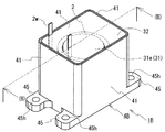
図1,図2A,図2Bを参照して、実施形態1のリアクトル1Aを説明する。リアクトル1Aは、巻線2wを螺旋状に巻回してなる筒状の一つのコイル2と、コイル2の内外に配置されて閉磁路を形成する磁性コア3と、コイル2と磁性コア3との組合体を収納するケース4Aとを具える。リアクトル1Aは、通常、冷却水の循環経路などといった冷却機構を具える冷却ベースなどの設置対象に設置され、上記冷却機構により冷却されて使用される。リアクトル1Aでは、ケース4Aが設置対象に固定される。磁性コア3は、コイル2の内側に配置される内側コア部31と、コイル2の外周を覆うように設けられた外側コア部32とを具える。リアクトル1Aの特徴とするところは、筒状のコイル2の外側に配置される箇所:外側コア部32が複合材料により構成されており、この複合材料中における気泡の最大径が300μm以下である点にある。以下、各構成及びリアクトルの製造方法を順に説明する。
Embodiment 1
A reactor 1A according to Embodiment 1 will be described with reference to FIGS. 1, 2A, and 2B. A reactor 1A includes a coil 2w formed by spirally winding a winding 2w, a magnetic core 3 disposed inside and outside the coil 2 to form a closed magnetic circuit, and the coil 2 and the magnetic core 3 It includes a case 4A for storing the union. The reactor 1A is usually installed on an installation target such as a cooling base having a cooling mechanism such as a cooling water circulation path, and is used after being cooled by the cooling mechanism. In reactor 1A, case 4A is fixed to the installation target. The magnetic core 3 includes an inner core portion 31 disposed inside the coil 2 and an outer core portion 32 provided so as to cover the outer periphery of the coil 2. Reactor 1A is characterized in that it is located outside cylindrical coil 2: the outer core portion 32 is made of a composite material, and the maximum bubble diameter in this composite material is 300 μm or less. It is in. Hereinafter, each structure and the manufacturing method of a reactor are demonstrated in order.
[コイル]
コイル2は、1本の連続する巻線2wを螺旋状に巻回してなる筒状体である。巻線2wは、銅やアルミニウム、その合金といった導電性材料からなる導体の外周に、絶縁性材料(代表的にはポリアミドイミドといったエナメル材料)からなる絶縁被覆を具える被覆線が好適である。導体は、横断面形状が長方形状である平角線、円形状である丸線、多角形状である異形線などの種々の形状のものを利用できる。特に、平角線は、エッジワイズ巻きにしてエッジワイズコイルとすると、占積率が高いコイルとし易いことから、占積率を高めて小型なコイルを得易く、リアクトルの小型化に寄与する。ここでは、コイル2は、導体が銅製で、横断面形状が長方形状の平角線からなり、絶縁被覆がエナメルからなる被覆平角線をエッジワイズ巻きにして形成されたエッジワイズコイルとしている。
[coil]
The coil 2 is a cylindrical body formed by spirally winding one continuous winding 2w. The winding 2w is preferably a coated wire having an insulating coating made of an insulating material (typically an enamel material such as polyamideimide) on the outer periphery of a conductor made of a conductive material such as copper, aluminum, or an alloy thereof. The conductor may have various shapes such as a rectangular wire having a rectangular cross-sectional shape, a round wire having a circular shape, and a deformed wire having a polygonal shape. In particular, if the rectangular wire is edgewise-wound and used as an edgewise coil, it is easy to obtain a coil with a high space factor. Therefore, it is easy to obtain a small coil by increasing the space factor, which contributes to downsizing of the reactor. Here, the coil 2 is an edgewise coil formed by edgewise winding a rectangular wire whose conductor is made of copper and whose cross-sectional shape is a rectangular shape and whose insulating coating is made of enamel.
(端面形状)
コイル2の端面形状及び軸方向に直交する方向の断面形状は、図1,図2Bに示すように円形状が代表的である。円形状のコイルは、巻線に平角線を用いた場合でも巻回し易く、コイルの製造性に優れる上に、小型なコイルにし易い。その他、コイル2の端面形状は、非円形状であって、かつ曲線部を有する形状、例えば、楕円などの実質的に曲線のみからなる形状や、曲線部と直線部とを有する形状(例えば、長方形などの多角形の各角部を丸めた形状、直線と円弧とを組み合せてなるレーストラック状など)が挙げられる。直線部を具える形態では、直線部によりつくられる平面がケースの底面に平行するようにコイルをケースに収納することで、安定性に優れる上に、放熱性にも優れる。
(End face shape)
The end surface shape of the coil 2 and the cross-sectional shape in the direction orthogonal to the axial direction are typically circular as shown in FIGS. A circular coil is easy to wind even when a rectangular wire is used as a winding, and is excellent in coil manufacturability and is easily made into a small coil. In addition, the end face shape of the coil 2 is a non-circular shape and has a curved portion, for example, a shape consisting essentially of a curve such as an ellipse, or a shape having a curved portion and a straight portion (for example, For example, a shape obtained by rounding corners of a polygon such as a rectangle, or a racetrack formed by combining a straight line and an arc. In the form having a straight portion, the coil is housed in the case so that the flat surface formed by the straight portion is parallel to the bottom surface of the case, thereby providing excellent stability and heat dissipation.
(巻線の端部)
コイル2を形成する巻線2wの両端部は、図1に示すようにターン形成部分から適宜引き延ばされて、絶縁被覆が剥がされて露出された導体部分に、銅やアルミニウムなどの導電性材料からなる端子部材(図示せず)が接続される。この端子部材を介して、コイル2に電力供給を行う電源などの外部装置(図示せず)が接続される。巻線2wの導体部分と端子部材との接続には、TIG溶接などの溶接、圧着などが利用できる。なお、巻線2wの両端部の引き出し方向は一例であり、適宜変更することができる。
(End of winding)
Both ends of the winding 2w forming the coil 2 are appropriately extended from the turn forming portion as shown in FIG. 1, and the conductive portion such as copper or aluminum is exposed to the exposed conductor portion after the insulation coating is peeled off. A terminal member (not shown) made of a material is connected. An external device (not shown) such as a power source for supplying power is connected to the coil 2 through this terminal member. For the connection between the conductor portion of the winding 2w and the terminal member, welding such as TIG welding or crimping can be used. It should be noted that the pulling direction of both ends of the winding 2w is an example, and can be changed as appropriate.
(配置形態)
コイル2は、図2Aに示すようにコイル2の軸がケース4Aの底面40に実質的に平行するようにケース4A内に収納されている。端的に言うと、コイル2は、ケース4Aに対してコイル2が横長となるように収納されている(以下、この配置形態を横型形態と呼ぶ)。実質的に平行とは、外底面40o及び内底面40iの双方が平面で構成されて、コイル2の軸と両面40o,40iが平行な場合の他、外底面40o及び内底面40iの一部が平面で構成されておらず、コイル2の軸と平行にならない箇所が存在する場合(例えば、外底面40oが平面で構成され、内底面40iが凹凸形状である場合など)を含む。
(Arrangement form)
As shown in FIG. 2A, the coil 2 is housed in the case 4A so that the axis of the coil 2 is substantially parallel to the bottom surface 40 of the case 4A. In short, the coil 2 is accommodated so that the coil 2 is horizontally long with respect to the case 4A (hereinafter, this arrangement form is referred to as a horizontal form). The term “substantially parallel” means that both the outer bottom surface 40o and the inner bottom surface 40i are flat surfaces, and the axis of the coil 2 and both surfaces 40o, 40i are parallel, as well as a part of the outer bottom surface 40o and the inner bottom surface 40i. This includes a case where there is a portion that is not configured in a plane and is not parallel to the axis of the coil 2 (for example, the outer bottom surface 40o is configured in a plane and the inner bottom surface 40i is uneven).
[磁性コア]
磁性コア3は、図2Aおよび図2Bに示すようにコイル2内に挿通される柱状の内側コア部31と、内側コア部31の少なくとも一方の端面31e(ここでは両端面)、及びコイル2の外周面を覆うように形成された外側コア部32とを具え、コイル2を励磁した際に閉磁路を形成する。リアクトル1Aでは、磁性コア3が一様な材質から構成されておらず、部分的に材質が異なっており、部分的に磁気特性が異なる。具体的には、内側コア部31は、外側コア部32よりも飽和磁束密度が高く、外側コア部32は、内側コア部31よりも比透磁率が低い。
[Magnetic core]
2A and 2B, the magnetic core 3 includes a columnar inner core portion 31 inserted into the coil 2, at least one end surface 31e (here, both end surfaces) of the inner core portion 31, and the coil 2 The outer core 32 is formed so as to cover the outer peripheral surface, and a closed magnetic circuit is formed when the coil 2 is excited. In the reactor 1A, the magnetic core 3 is not made of a uniform material, the material is partially different, and the magnetic characteristics are partially different. Specifically, the inner core portion 31 has a higher saturation magnetic flux density than the outer core portion 32, and the outer core portion 32 has a lower relative permeability than the inner core portion 31.
(内側コア部)
内側コア部31は、コイル2の内周形状に沿った円柱体である。ここでは、図2Aに示すように内側コア部31におけるコイル2の軸方向に沿った長さ(以下、単に長さと呼ぶ)がコイル2の長さよりも長く、コイル2の内側に挿通配置された状態において内側コア部31の両端面31e及びその近傍の外周面がコイル2の端面から若干突出している。内側コア部31の突出長さは適宜選択することができる。ここでは、内側コア部31においてコイル2の各端面から突出する突出長さを等しくしているが、後述する実施形態2のように異ならせてもよいし、コイル2のいずれか一方の端面からのみ突出部分が存在するように内側コア部の長さやコイルに対する配置位置を調整してもよい。また、内側コア部の長さとコイルの長さとが等しい形態、内側コア部の長さがコイルの長さよりも短い形態とすることもできるが、図2A,図4(B)に示すように内側コア部31の長さがコイル2の長さと同等以上であると、コイル2がつくる磁束を内側コア部31に十分に通過させることができて好ましい。
(Inner core)
The inner core portion 31 is a cylindrical body along the inner peripheral shape of the coil 2. Here, as shown in FIG. 2A, the length of the inner core portion 31 along the axial direction of the coil 2 (hereinafter simply referred to as the length) is longer than the length of the coil 2 and is inserted and arranged inside the coil 2. In the state, both end surfaces 31e of the inner core portion 31 and the outer peripheral surface in the vicinity thereof slightly protrude from the end surface of the coil 2. The protruding length of the inner core portion 31 can be appropriately selected. Here, the protruding lengths protruding from the end faces of the coil 2 in the inner core portion 31 are made equal, but they may be different as in Embodiment 2 described later, or from either one end face of the coil 2 You may adjust the length of an inner core part, and the arrangement position with respect to a coil so that only a protrusion part exists. In addition, the length of the inner core portion and the length of the coil may be equal, and the length of the inner core portion may be shorter than the length of the coil, but as shown in FIGS. 2A and 4 (B) It is preferable that the length of the core portion 31 is equal to or greater than the length of the coil 2 because the magnetic flux generated by the coil 2 can be sufficiently passed through the inner core portion 31.
ここでは、内側コア部31は、絶縁被膜などの被膜を具える軟磁性材料からなる圧粉成形体から構成されている。圧粉成形体は、代表的には、表面にシリコーン樹脂などからなる絶縁被膜を具える軟磁性粉末や、この軟磁性粉末に加えて適宜結合剤を混合した混合粉末を成形後、上記絶縁被膜の耐熱温度以下で焼成することにより得られる。圧粉成形体の作製にあたり、軟磁性粉末の材質や、軟磁性粉末と結合剤との混合比、絶縁被膜を含む種々の被膜の量などを調整したり、成形圧力を調整したりすることで飽和磁束密度を変化させることができる。例えば、飽和磁束密度の高い軟磁性粉末を用いたり、結合剤の配合量を低減して軟磁性材料の割合を高めたり、成形圧力を高くしたりすることで、飽和磁束密度が高い圧粉成形体が得られる。
Here, the inner core portion 31 is composed of a compacted body made of a soft magnetic material having a coating such as an insulating coating. The green compact is typically formed by molding a soft magnetic powder having an insulating coating made of a silicone resin or the like on the surface, or a mixed powder in which a binder is appropriately mixed in addition to the soft magnetic powder, and then forming the insulating coating. It can be obtained by firing at a temperature lower than the heat resistant temperature. In the production of green compacts, by adjusting the material of the soft magnetic powder, the mixing ratio of the soft magnetic powder and the binder, the amount of various coatings including the insulating coating, etc., and adjusting the molding pressure The saturation magnetic flux density can be changed. For example, by using soft magnetic powder with a high saturation magnetic flux density, increasing the proportion of soft magnetic material by reducing the amount of binder, or increasing the molding pressure, compacting with high saturation magnetic flux density The body is obtained.
上記軟磁性粉末は、Fe,Co,Niなどの鉄族金属、Feを主成分とするFe基合金、例えばFe-Si,Fe-Ni,Fe-Al,Fe-Co,Fe-Cr,Fe-Si-Alなどといった鉄基材料からなる粉末、希土類金属粉末、フェライト粉末などが挙げられる。特に、鉄基材料は、フェライトよりも飽和磁束密度が高い磁性コアを得易い。軟磁性粉末に形成される絶縁被膜の構成材料は、例えば、燐酸化合物、珪素化合物、ジルコニウム化合物、アルミニウム化合物、硼素化合物などが挙げられる。この絶縁被覆は、特に軟磁性粉末を構成する磁性粒子が鉄族金属やFe基合金といった金属からなる場合に具えると、渦電流損を効果的に低減できる。結合剤は、例えば、熱可塑性樹脂、非熱可塑性樹脂、高級脂肪酸が挙げられる。この結合剤は、上述の焼成により消失したり、シリカなどの絶縁物に変化したりする。圧粉成形体は、複雑な立体形状であっても比較的容易に成形可能である上に、磁性粒子間に絶縁被膜などの絶縁物が存在することで、磁性粒子同士が絶縁されて渦電流損を低減でき、コイルに高周波の電力が通電される場合であっても、上述の損失を低減できる。圧粉成形体は、公知のものを利用することができる。柱状の内側コア部31は、所望の形状の金型を用いて成形した一体物としたり、複数のコア片を接着剤や接着テープなどで固定して一体物としたりすることで得られる。
The soft magnetic powder is an iron group metal such as Fe, Co, Ni, Fe-based alloy containing Fe as a main component, for example, Fe-Si, Fe-Ni, Fe-Al, Fe-Co, Fe-Cr, Fe- Examples thereof include powders made of iron-based materials such as Si-Al, rare earth metal powders, and ferrite powders. In particular, the iron-based material is easy to obtain a magnetic core having a saturation magnetic flux density higher than that of ferrite. Examples of the constituent material of the insulating coating formed on the soft magnetic powder include a phosphoric acid compound, a silicon compound, a zirconium compound, an aluminum compound, and a boron compound. This insulation coating can effectively reduce eddy current loss, especially when the magnetic particles constituting the soft magnetic powder are made of a metal such as an iron group metal or an Fe group alloy. Examples of the binder include thermoplastic resins, non-thermoplastic resins, and higher fatty acids. This binder disappears by the above-mentioned baking, or changes to an insulator such as silica. The compacted body can be molded relatively easily even in a complicated three-dimensional shape. In addition, the presence of an insulator such as an insulating film between the magnetic particles insulates the magnetic particles from each other, resulting in an eddy current. The loss can be reduced, and the above-described loss can be reduced even when high-frequency power is supplied to the coil. A well-known thing can be utilized for a compacting body. The columnar inner core portion 31 can be obtained by making it an integrated product formed by using a mold having a desired shape, or by fixing a plurality of core pieces with an adhesive or an adhesive tape.
ここでは、内側コア部31は、ギャップ材やエアギャップが介在していない中実体としている。ギャップを有さないことで小型にできる上に、ギャップ部分の漏れ磁束がコイル2に影響を及ぼさないため、コイル2と内側コア部31とを近接でき、この点からもリアクトル1Aを小型にできる。更に、ギャップの省略により、損失の低減や、大電流の通電時におけるインダクタンスの低下の低減を図ることができる。なお、磁性コア3は、圧粉成形体や後述の複合材料よりも比透磁率が低い材料、代表的にはアルミナ板などの非磁性材料からなるギャップ材やエアギャップが介在した形態としてもよい。或いは、比透磁率が1よりも大きいギャップ材が介在した形態としてもよい。このギャップ材の構成材料は、非磁性材料(例えば、不飽和ポリエステルなどの樹脂)中に鉄やFe-Siなどの磁性体粉末を分散させたものが挙げられる。比透磁率が1よりも大きいギャップ材、いわば磁性を有するギャップ材を具えることで、リアクトルのインダクタンスを調整し易い。このギャップ材の厚さが必要以上に厚くならないようにするため、当該ギャップ材の比透磁率は、1超5以下が好ましく、更に1.1以上1.4以下が好ましい。
Here, the inner core portion 31 is a solid body in which no gap material or air gap is interposed. In addition to being able to reduce the size by not having a gap, since the leakage magnetic flux in the gap does not affect the coil 2, the coil 2 and the inner core portion 31 can be brought close to each other, and from this point, the reactor 1A can also be reduced in size. . Further, by omitting the gap, it is possible to reduce loss and decrease in inductance when a large current is applied. The magnetic core 3 may have a form in which a compact material or a material having a lower relative permeability than a composite material described later, typically a gap material made of a nonmagnetic material such as an alumina plate, or an air gap is interposed. . Alternatively, a gap material having a relative permeability greater than 1 may be interposed. Examples of the constituent material of the gap material include a material in which a magnetic powder such as iron or Fe—Si is dispersed in a nonmagnetic material (for example, a resin such as unsaturated polyester). By providing a gap material having a relative permeability greater than 1, that is, a gap material having magnetism, it is easy to adjust the inductance of the reactor. In order to prevent the gap material from becoming unnecessarily thick, the relative permeability of the gap material is preferably more than 1 and 5 or less, and more preferably 1.1 or more and 1.4 or less.
(外側コア部)
外側コア部32は、ここでは、コイル2の両端面と外周面の実質的に全てと、内側コア部31の両端面31e及びその近傍の外周面とを覆っており、ケース4Aの内周面と、ケース4Aに収納されたコイル2と内側コア部31との組物の外周面とがつくる空間に沿った形状である。
外側コア部32の一部が内側コア部31の両端面31eに連結するように設けられていることで、磁性コア3は閉磁路を形成する。
(Outer core)
Here, the outer core portion 32 covers substantially all of the both end surfaces and the outer peripheral surface of the coil 2, the both end surfaces 31e of the inner core portion 31 and the outer peripheral surface in the vicinity thereof, and the inner peripheral surface of the case 4A. And the shape along the space formed by the outer peripheral surface of the assembly of the coil 2 housed in the case 4A and the inner core portion 31.
The magnetic core 3 forms a closed magnetic path by providing a part of the outer core part 32 so as to be connected to both end faces 31e of the inner core part 31.
そして、外側コア部32は、その全体が磁性体粉末と樹脂とを含有する複合材料により形成されており、この複合材料の断面をとったとき、気泡の最大径が300μm以下である。
The entire outer core portion 32 is formed of a composite material containing a magnetic powder and a resin. When the cross section of the composite material is taken, the maximum bubble diameter is 300 μm or less.
磁性体粉末と樹脂とを含有する複合材料は、代表的には、射出成形、注型成形により製造することができる。射出成形では、通常、磁性体粉末と流動性のある状態の樹脂(液状の樹脂)とを混合し、この混合流体を、所定の圧力をかけて成形型(ケース4Aを含む)に流し込んで成形した後、上記樹脂を硬化することで複合材料が得られる。注型成形では、射出成形と同様の混合流体を得た後、この混合流体を、圧力をかけることなく成形型に注入して成形・硬化することで複合材料が得られる。特に、気泡の最大径が300μm以下である複合材料は、後述する特定の条件で混合流体を作製して成形型に充填すると共に、特定の脱気工程を経ることで得られる。実施形態1ではケース4を成形型に利用している。この場合、複雑な形状の複合材料であっても、容易に成形できる。所望の形状の成形体を複数作製して組み合せて、所望の形状の磁性コアを形成することもできる。
A composite material containing magnetic powder and resin can be typically produced by injection molding or cast molding. In injection molding, normally, magnetic powder and fluid resin (liquid resin) are mixed, and this mixed fluid is poured into a mold (including case 4A) under a predetermined pressure. Then, the composite material is obtained by curing the resin. In cast molding, a composite material is obtained by obtaining a mixed fluid similar to that of injection molding, and then injecting the mixed fluid into a molding die without applying pressure and molding and curing. In particular, a composite material having a maximum bubble diameter of 300 μm or less can be obtained by preparing a mixed fluid under specific conditions described later and filling it into a mold, and through a specific degassing step. In the first embodiment, the case 4 is used as a mold. In this case, even a complex shaped composite material can be easily molded. A plurality of molded bodies having a desired shape can be produced and combined to form a magnetic core having a desired shape.
〔気泡〕
上記複合材料の断面は、コイル2の軸方向に沿って切断した断面、及び軸方向に直交する方向に切断した断面のいずれでもよい。気泡の最大径は、複合材料について一定の大きさの視野(例えば、5mm×7mm)の断面を複数とり(例えば、10断面)、各断面中に存在する気泡の輪郭から当該輪郭の円相当径(各断面において確認できる気泡の形状を、同じ面積の円に変換したときの直径)を算出し、この円相当径を気泡の直径とするとき、上記複数の断面中における気泡の直径の最大値とする。上記断面を光学顕微鏡などで観察し(10倍~50倍程度)、観察像を市販の画像処理装置により画像処理することで、気泡の輪郭の抽出や円相当径の算出を容易に行える。磁気特性や損失への影響を考慮すると、気泡はできるだけ微小であることが好ましい。従って、気泡の最大径は、小さいほど好ましく、200μm以下、更に100μm以下がより好ましい。
[Bubbles]
The cross section of the composite material may be either a cross section cut along the axial direction of the coil 2 or a cross section cut along a direction orthogonal to the axial direction. The maximum diameter of bubbles is a plurality of cross-sections (for example, 10 cross-sections) of a fixed-size visual field (e.g., 5 mm x 7 mm) for the composite material, and the equivalent circle diameter of the outline from the outline of the bubbles present in each cross-section (The diameter when the shape of the bubble that can be confirmed in each cross section is converted into a circle of the same area) is calculated, and when this equivalent circle diameter is the diameter of the bubble, the maximum value of the diameter of the bubble in the plurality of cross sections And By observing the cross section with an optical microscope or the like (about 10 to 50 times) and processing the observed image with a commercially available image processing apparatus, it is possible to easily extract the outline of bubbles and calculate the equivalent circle diameter. In consideration of the influence on magnetic characteristics and loss, it is preferable that the bubbles are as small as possible. Accordingly, the maximum bubble diameter is preferably as small as possible, more preferably 200 μm or less, and even more preferably 100 μm or less.
最大径が300μm以下の気泡が数多く存在すると、粗大な気泡が存在する場合と同様に、気泡に起因する磁束の迂回によって複合材料中に磁束線の粗密が局所的に生じて、磁気特性の低下や熱伝導率の低下を招く恐れがある。そのため、気泡の最大径が300μm以下であることに加えて、気泡の数もできるだけ少ないことが好ましい。即ち、気泡の含有量自体もできるだけ少ないことが好ましい。具体的には、上記複合材料の断面における気泡の合計面積割合は、1%以下が好ましい。更に、上記複合材料の断面における気泡の合計面積割合は、直径300μmの球状の気泡が1個存在し、この気泡の直径を通る断面円の面積割合以下、具体的には、0.2%以下がより好ましい。なお、直径300μm(0.3mm)の球状の気泡の直径を通る断面円の面積は、(半径0.15mmの2乗)×π≒0.07mm2である。従って、この球状の気泡が1個存在した場合に、5mm×7mm(35mm2)の視野の断面積に対する当該気泡の直径を通る断面円の面積割合は、(0.07/35)×100=0.2%となる。
When there are many bubbles with a maximum diameter of 300 μm or less, as in the case of the presence of coarse bubbles, the magnetic flux lines due to the bubbles bypass the magnetic flux lines locally in the composite material, resulting in a decrease in magnetic properties. There is a risk of lowering thermal conductivity. Therefore, in addition to the maximum bubble diameter being 300 μm or less, the number of bubbles is preferably as small as possible. That is, the bubble content itself is preferably as small as possible. Specifically, the total area ratio of bubbles in the cross section of the composite material is preferably 1% or less. Further, the total area ratio of the bubbles in the cross section of the composite material is one spherical bubble having a diameter of 300 μm, and is less than the area ratio of the cross-sectional circle passing through the diameter of the bubbles, specifically 0.2% or less. preferable. The area of the cross-sectional circle passing through the diameter of a spherical bubble having a diameter of 300 μm (0.3 mm) is (square of radius 0.15 mm) × π≈0.07 mm 2 . Therefore, when one spherical bubble is present, the area ratio of the cross-sectional circle passing through the diameter of the bubble to the cross-sectional area of the visual field of 5 mm × 7 mm (35 mm 2 ) is (0.07 / 35) × 100 = 0.2% It becomes.
上記合計面積割合とは、上述の5mm×7mmの視野の断面積に対する気泡の合計面積の割合とする。視野は、その面積が35±5mm2を満たせばよく、その形状は、長方形状、正方形状が挙げられる。
The total area ratio is the ratio of the total area of bubbles to the cross-sectional area of the 5 mm × 7 mm field of view described above. The visual field only needs to satisfy an area of 35 ± 5 mm 2, and examples of the shape include a rectangular shape and a square shape.
〔磁性体粉末〕
外側コア部32を構成する複合材料中の磁性体粉末は、上述した内側コア部31を構成する圧粉成形体の軟磁性粉末と同様の組成でも異なる組成でもよい。外側コア部32を構成する複合材料は、非磁性材料である樹脂を比較的多く含有することから、上記磁性体粉末が内側コア部31を構成する圧粉成形体と同じ組成の軟磁性粉末であっても、上記圧粉成形体よりも飽和磁束密度が低く、かつ比透磁率も低くなる。外側コア部32を構成する磁性体粉末は、純鉄粉末やFe基合金粉末といった鉄基材料からなるものが好適である。また、上記磁性体粉末は、材質の異なる複数種の粉末を混合したものでもよい。上記磁性体粉末が特に金属材料で構成される場合、当該粉末を構成する各粒子の表面に燐酸塩などからなる絶縁被膜を具える被覆粉末であると、渦電流損を低減できる。
[Magnetic powder]
The magnetic substance powder in the composite material constituting the outer core part 32 may have the same composition as or a different composition from the soft magnetic powder of the compacting body constituting the inner core part 31 described above. Since the composite material constituting the outer core portion 32 contains a relatively large amount of a resin that is a nonmagnetic material, the magnetic powder is a soft magnetic powder having the same composition as the green compact forming the inner core portion 31. Even if it exists, a saturation magnetic flux density is lower than the said compacting body, and a relative magnetic permeability also becomes low. The magnetic substance powder constituting the outer core portion 32 is preferably made of an iron-based material such as pure iron powder or Fe-based alloy powder. The magnetic powder may be a mixture of a plurality of types of powders having different materials. When the magnetic powder is made of a metal material, eddy current loss can be reduced if the surface of each particle constituting the powder is a coating powder having an insulating coating made of phosphate or the like.
外側コア部32を構成する複合材料中の磁性体粉末の平均粒径は、1μm以上1000μm以下、特に10μm以上500μm以下が好ましい。ここで、外側コア部32を構成する複合材料中の磁性体粉末と、原料に用いる粉末とは、その大きさが実質的に同じである(維持されている)。原料粉末に上記範囲の大きさの粉末を用いると、混合流体が流動性に優れるため、複合材料の製造性に優れる。上記磁性体粉末は、粒径が異なる複数種の粉末を含んでいてもよい。磁性体粉末が微細粉末と粗大粉末とを含む複合材料を磁性コアに用いることで、飽和磁束密度が高く、低損失なリアクトルが得られ易い。
The average particle diameter of the magnetic powder in the composite material constituting the outer core portion 32 is preferably 1 μm or more and 1000 μm or less, and particularly preferably 10 μm or more and 500 μm or less. Here, the magnetic powder in the composite material constituting the outer core portion 32 and the powder used as the raw material have substantially the same size (maintained). When a powder having a size in the above range is used as the raw material powder, the mixed fluid is excellent in fluidity, so that the productivity of the composite material is excellent. The magnetic powder may include a plurality of types of powders having different particle sizes. By using a composite material in which the magnetic powder includes a fine powder and a coarse powder for the magnetic core, it is easy to obtain a reactor having a high saturation magnetic flux density and a low loss.
外側コア部32を構成する複合材料中の磁性体粉末の含有量は、複合材料を100%とするとき、30体積%以上70体積%以下、更に40体積%以上65体積%以下、特に40体積%以上60体積%以下が挙げられる。磁性体粉末が30体積%以上であることで、磁性成分の割合が十分に高いため飽和磁束密度といった磁気特性を高め易い。特に、磁性体粉末が鉄やFe-Si合金のような飽和磁束密度が2T程度の材質から構成される場合、磁性体粉末の含有量が30体積%以上であることで飽和磁束密度を0.6T以上にし易く、40体積%以上であることで飽和磁束密度を0.8T以上にし易くなる。磁性体粉末が70体積%以下であることで、製造時、磁性体粉末と樹脂とを混合し易くなり、製造性に優れる。
The content of the magnetic powder in the composite material constituting the outer core portion 32 is 30% to 70% by volume, further 40% to 65% by volume, especially 40%, when the composite material is 100%. % Or more and 60% by volume or less. When the magnetic powder is at least 30% by volume, the magnetic component ratio is sufficiently high, so that magnetic properties such as saturation magnetic flux density can be easily improved. In particular, when the magnetic powder is made of a material having a saturation magnetic flux density of about 2T, such as iron or Fe-Si alloy, the saturation magnetic flux density is 0.6T because the content of the magnetic powder is 30% by volume or more. The saturation magnetic flux density can be easily increased to 0.8 T or more by being 40% by volume or more. When the magnetic substance powder is 70% by volume or less, it becomes easy to mix the magnetic substance powder and the resin at the time of production, and the productivity is excellent.
〔樹脂〕
外側コア部32を構成する複合材料においてバインダとなる樹脂は、代表的には、エポキシ樹脂、フェノール樹脂、シリコーン樹脂、ウレタン樹脂、不飽和ポリエステルなどの熱硬化性樹脂が挙げられる。その他、バインダとなる樹脂として、熱可塑性樹脂、常温硬化性樹脂、或いは低温硬化性樹脂を利用することができる。熱可塑性樹脂は、例えば、ポリフェニレンサルファイド(PPS)樹脂、ポリイミド樹脂、フッ素樹脂などが挙げられる。
〔resin〕
The resin that serves as the binder in the composite material that forms the outer core portion 32 typically includes a thermosetting resin such as an epoxy resin, a phenol resin, a silicone resin, a urethane resin, or an unsaturated polyester. In addition, a thermoplastic resin, a room temperature curable resin, or a low temperature curable resin can be used as a resin serving as a binder. Examples of the thermoplastic resin include polyphenylene sulfide (PPS) resin, polyimide resin, and fluororesin.
〔その他の含有物〕
複合材料の一形態として、磁性体粉末及びバインダとなる樹脂に加えて、アルミナやシリカといったセラミックスからなるフィラー(代表的には、非磁性体粉末)を混合した形態が挙げられる。磁性体粉末に比較して比重が小さい上記フィラーを混合することで、磁性体粉末の偏在を抑制して、全体に磁性体粉末が均一的に分散した複合材料とすることができる。或いは、上記フィラーが熱伝導性に優れる材料から構成される場合、放熱性の向上に寄与することができる。上記フィラーの含有量は、複合材料を100質量%とするとき、0.2質量%以上が挙げられる。上記フィラーの含有量が多いほど、磁性体粉末の偏在の低減や放熱性の向上などの効果が得られるため、0.3質量%以上、更に0.5質量%以上が好ましい。一方、上記フィラーが多過ぎると磁性体粉末の割合の低下を招くことから、上記フィラーの含有量は20質量%以下、更に15質量%以下、特に10質量%以下が好ましい。上記フィラーは、磁性体粉末よりも微粒にすると磁性体粒子間に介在させ易く、当該フィラーの含有による磁性体粉末の割合の低下を抑制し易い。
[Other contents]
As one form of the composite material, a form in which a filler (typically a non-magnetic powder) made of ceramics such as alumina or silica is mixed in addition to a magnetic powder and a resin serving as a binder. By mixing the filler having a specific gravity smaller than that of the magnetic powder, uneven distribution of the magnetic powder can be suppressed and a composite material in which the magnetic powder is uniformly dispersed can be obtained. Or when the said filler is comprised from the material which is excellent in heat conductivity, it can contribute to the improvement of heat dissipation. The content of the filler is 0.2% by mass or more when the composite material is 100% by mass. As the content of the filler is increased, effects such as a reduction in uneven distribution of the magnetic powder and an improvement in heat dissipation can be obtained. Therefore, the content is preferably 0.3% by mass or more, and more preferably 0.5% by mass or more. On the other hand, if the filler is too much, the proportion of the magnetic powder is reduced, so the filler content is preferably 20% by mass or less, more preferably 15% by mass or less, and particularly preferably 10% by mass or less. When the filler is finer than the magnetic powder, it is easy to interpose between the magnetic particles, and it is easy to suppress a decrease in the ratio of the magnetic powder due to the inclusion of the filler.
ここでは、外側コア部32は、平均粒径75μm以下の鉄基材料(純鉄)からなる粒子の表面に上記絶縁被膜を具える被覆粉末とエポキシ樹脂との複合材料から構成されている(複合材料中の純鉄粉の含有量:45体積%)。
Here, the outer core part 32 is composed of a composite material of a coating powder and an epoxy resin having the insulating coating on the surface of particles made of an iron-based material (pure iron) having an average particle diameter of 75 μm or less (composite). Content of pure iron powder in the material: 45% by volume).
〔磁性体粉末の存在状態〕
複合材料中の磁性体粉末は、当該粉末を構成する磁性体粒子が複合材料中に均一的に分散した形態が代表的である。その他、後述するように脱気工程において保持時間を長くすることで、成形型の底面側(ここではケース4Aの底面40側)に磁性体粉末が多く存在する分布をとる形態とすることができる。つまり、外側コア部32においてケース4Aの底面40側の磁性体粉末の存在割合と、底面40に対向する開口側の磁性体粉末の存在割合とを比較すると、底面40側の存在割合が大きい形態とすることができる。
[Presence of magnetic powder]
The magnetic powder in the composite material is typically in a form in which the magnetic particles constituting the powder are uniformly dispersed in the composite material. In addition, as will be described later, by extending the holding time in the deaeration step, it is possible to adopt a form in which a large amount of magnetic powder is present on the bottom surface side of the mold (here, the bottom surface 40 side of the case 4A). . That is, in the outer core portion 32, when the proportion of the magnetic powder on the bottom surface 40 side of the case 4A is compared with the proportion of the magnetic powder on the opening side facing the bottom surface 40, the form in which the presence ratio on the bottom surface 40 side is large. It can be.
〔形状〕
外側コア部32は、閉磁路が形成できればよく、その形状は特に問わない。ここでは、上述のように外側コア部32を構成する複合材料がコイル2と内側コア部31との組物の実質的に全周を覆うことから、外側コア部32は、コイル2や内側コア部31の封止材としても機能し、コイル2の外部環境から保護や機械的保護の強化を図ることができる。
〔shape〕
The outer core portion 32 is not particularly limited as long as a closed magnetic path can be formed. Here, since the composite material constituting the outer core portion 32 covers substantially the entire circumference of the assembly of the coil 2 and the inner core portion 31 as described above, the outer core portion 32 is the coil 2 or the inner core. It also functions as a sealing material for the portion 31, and can enhance protection and mechanical protection from the external environment of the coil 2.
例えば、コイル2の外周の一部が外側コア部32を構成する複合材料により覆われない形態とすることができる。具体的は、例えば、コイル2の外周面においてケース4Aの開口側に配置される領域が上記複合材料に覆われず露出された形態、コイル2において底面側に配置される領域の一部を収納可能な溝をケース4Aの底面に設けて、この溝に収納された箇所が上記複合材料に覆われない形態が挙げられる。上記形態は、コイル2においてケース4Aの底面から最も離れた開口側の領域が露出されたり、ケース4Aとの接触箇所が多くなったりすることで、放熱性を高められる。コイル2の一部を露出させる形態では、ケースの開口部を覆う蓋を具えることが好ましい。この蓋を金属といった導電性材料(ケースと同じ材質でもよい)により構成すると、コイル2の露出箇所から外部への漏れ磁束を抑制できる上に、この蓋を放熱経路にも利用できる。
For example, a part of the outer periphery of the coil 2 may not be covered with the composite material constituting the outer core portion 32. Specifically, for example, a form in which the region disposed on the opening side of the case 4A on the outer peripheral surface of the coil 2 is exposed without being covered with the composite material, and a part of the region disposed on the bottom side in the coil 2 is stored. A possible groove is provided on the bottom surface of the case 4A, and the portion housed in the groove is not covered with the composite material. In the above-described form, heat dissipation is improved by exposing the region on the opening side farthest from the bottom surface of the case 4A in the coil 2 or increasing the number of contact points with the case 4A. In the form in which a part of the coil 2 is exposed, it is preferable to provide a lid that covers the opening of the case. If the lid is made of a conductive material such as metal (may be the same material as the case), the leakage flux from the exposed portion of the coil 2 to the outside can be suppressed, and the lid can also be used as a heat dissipation path.
或いは、ケース4Aの内底面40iにコイル2の位置決め部材(図示せず)を別途配置し、コイル2においてこの位置決め部材との接触部分が外側コア部を構成する複合材料により覆われない形態とすることができる。位置決め部材の材質は、コイル2とケース4Aとの間の絶縁性を高められるように絶縁性材料が好ましく、放熱性に優れる材料であると、放熱性を高められる。この位置決め部材とコイル2とは、外側コア部32を構成する複合材料により封止されることで、相互の位置が固定される。
Alternatively, a positioning member (not shown) for the coil 2 is separately arranged on the inner bottom surface 40i of the case 4A, and the contact portion with the positioning member in the coil 2 is not covered with the composite material constituting the outer core portion. be able to. The material of the positioning member is preferably an insulating material so that the insulating property between the coil 2 and the case 4A can be improved. If the material is excellent in heat dissipation, the heat dissipation can be improved. The positioning member and the coil 2 are sealed with a composite material constituting the outer core portion 32, so that the mutual positions are fixed.
内側コア部31の一部も外側コア部32を構成する複合材料により覆われていない形態とすることができる。例えば、内側コア部31におけるコイル2の端面から突出した箇所を支持する支持部材を具え、内側コア部31においてこの支持部材との接触箇所が上記複合材料により覆われない形態が挙げられる。支持部材により内側コア部31は、ケース4Aに対して位置決めされ、内側コア部31が位置決めされることで、コイル2の位置決めも行える。更に、それぞれの位置は、外側コア部32を構成する複合材料により封止されることで固定される。従って、この支持部材を具える場合、上述のコイル2の位置決め部材を省略してもよい。内側コア部31とコイル2とが適切な位置に固定されることで、インダクタンスを設定値通りにし易い。この支持部材は、ケース4Aに一体に成形されたものでもよいし、上記複合材料やその他の材料により作製した別部材としてもよい。支持部材も放熱性に優れる材料により構成することで、放熱性を高められる。また、支持部材の大きさを調整して、内側コア部31を支持した状態においてコイル2とケース4Aの内底面40iとの両者間に隙間を有する形態とすると、両者間の絶縁性を高められ、両者が接触する形態とすると、放熱性を高められる。
A part of the inner core portion 31 may be not covered with the composite material constituting the outer core portion 32. For example, there is a configuration in which a support member that supports a portion protruding from the end face of the coil 2 in the inner core portion 31 is provided, and the contact portion with the support member in the inner core portion 31 is not covered with the composite material. The inner core portion 31 is positioned with respect to the case 4A by the support member, and the coil 2 can be positioned by positioning the inner core portion 31. Furthermore, each position is fixed by being sealed with the composite material constituting the outer core portion 32. Accordingly, when the support member is provided, the positioning member for the coil 2 described above may be omitted. By fixing the inner core portion 31 and the coil 2 at appropriate positions, the inductance can be easily set to the set value. This support member may be formed integrally with the case 4A, or may be a separate member made of the composite material or other material. The support member is also made of a material having excellent heat dissipation, so that the heat dissipation can be improved. Further, by adjusting the size of the support member and supporting the inner core portion 31 so as to have a gap between the coil 2 and the inner bottom surface 40i of the case 4A, the insulation between the two can be improved. And if it is set as the form which both contact, heat dissipation is improved.
〔内側コア部と外側コア部との接合〕
内側コア部31と外側コア部32とは接着剤を介在することなく、外側コア部32を構成する複合材料中の樹脂により接合されている。また、ここでは、外側コア部32もギャップ材やエアギャップが介在しておらず、磁性コア3は、その全体に亘ってギャップ材を介することなく一体化された一体化物である。従って、リアクトル1Aでは、磁性コア3の製造に当たり、接着剤などで接合する工程が不要であり、リアクトル1Aの生産性に優れる。
[Bonding of inner core and outer core]
The inner core portion 31 and the outer core portion 32 are joined by a resin in the composite material constituting the outer core portion 32 without interposing an adhesive. Also, here, the outer core portion 32 is also free of gap material or air gap, and the magnetic core 3 is an integrated product that is integrated without any gap material. Therefore, in the reactor 1A, when the magnetic core 3 is manufactured, the step of joining with an adhesive or the like is unnecessary, and the productivity of the reactor 1A is excellent.
内側コア部31と外側コア部32とを接着剤により接合することも可能である。また、ギャップ材を具える形態では、内側コア部31と外側コア部32とギャップ材とを接着剤により接合することも可能である。接着剤により接合する場合には、複数の接着工程に分けて接合することができる。接着剤が十分に少ない場合、接着剤は、実質的にギャップ材として機能していないと考えられる。
It is also possible to join the inner core portion 31 and the outer core portion 32 with an adhesive. Further, in the form including the gap material, the inner core portion 31, the outer core portion 32, and the gap material can be joined with an adhesive. In the case of bonding with an adhesive, the bonding can be performed in a plurality of bonding steps. When the adhesive is sufficiently small, it is considered that the adhesive does not substantially function as a gap material.
(磁気特性)
ここでは、内側コア部31は、飽和磁束密度:1.6T以上、かつ外側コア部32の1.2倍以上、比透磁率:100以上500以下、外側コア部32は、飽和磁束密度:0.5T以上内側コア部31の飽和磁束密度未満、比透磁率:5以上30以下、内側コア部31及び外側コア部32からなる磁性コア3全体(実質的に、ギャップ材やエアギャップを介在させていない場合)の比透磁率は10以上100以下である。一定の磁束を得る場合、内側コア部の飽和磁束密度の絶対値が高いほど、また、内側コア部の飽和磁束密度が外側コア部よりも相対的に大きいほど、内側コア部の断面積を小さくし易い。そのため、内側コア部の飽和磁束密度が高い形態は、全体の飽和磁束密度が均一的な磁性コアと同じ磁束を得る場合、内側コア部の断面積の小型化により、リアクトルの小型化に寄与することができる。内側コア部31の飽和磁束密度は、1.8T以上、更に2T以上が好ましく、外側コア部32の飽和磁束密度の1.5倍以上、更に1.8倍以上が好ましく、いずれも上限は設けない。圧粉成形体に代えて、珪素鋼板に代表される電磁鋼板の積層体を利用すると、内側コア部の飽和磁束密度を更に高め易い。一方、外側コア部32の比透磁率を内側コア部31よりも低くすると、例えば、内側コア部31に磁束を通過し易い。また、比透磁率が低い箇所を具えることで、磁気飽和を抑制できるためギャップレス構造の磁性コア3としたりすることができる。
(Magnetic properties)
Here, the inner core portion 31 has a saturation magnetic flux density of 1.6 T or more and 1.2 times or more of the outer core portion 32, a relative magnetic permeability of 100 to 500, and the outer core portion 32 has an inner saturation magnetic flux density of 0.5 T or more. Less than the saturation magnetic flux density of the core part 31, relative permeability: 5 or more and 30 or less, the entire magnetic core 3 consisting of the inner core part 31 and the outer core part 32 (when substantially no gap material or air gap is interposed) The relative magnetic permeability is 10 or more and 100 or less. When obtaining a constant magnetic flux, the higher the absolute value of the saturation magnetic flux density of the inner core part, and the smaller the saturation magnetic flux density of the inner core part relative to the outer core part, the smaller the cross-sectional area of the inner core part. Easy to do. Therefore, when the saturation magnetic flux density of the inner core portion is high, when the same saturation magnetic flux density as the magnetic core is obtained, the inner core portion contributes to the reduction of the reactor by reducing the cross-sectional area of the inner core portion. be able to. The saturation magnetic flux density of the inner core portion 31 is preferably 1.8 T or more, more preferably 2 T or more, more preferably 1.5 times or more, and more preferably 1.8 times or more of the saturation magnetic flux density of the outer core portion 32, and no upper limit is provided. If a laminated body of electromagnetic steel sheets typified by silicon steel sheets is used instead of the green compact, the saturation magnetic flux density of the inner core portion can be further increased. On the other hand, when the relative permeability of the outer core portion 32 is lower than that of the inner core portion 31, for example, magnetic flux easily passes through the inner core portion 31. In addition, since the magnetic saturation can be suppressed by providing a portion having a low relative magnetic permeability, the magnetic core 3 having a gapless structure can be obtained.
[コイルと磁性コア間の介在物]
コイル2と磁性コア3との両者間の絶縁性を高めるために、両者間に絶縁部材を介在させた形態とすることができる。例えば、コイル2の外周面や内周面に絶縁テープを貼り付けたり、コイル2の外周面や内周面を絶縁紙や絶縁シートで覆ったりすることが挙げられる。或いは、内側コア部31の外側やコイル2の外側に筒状のインシュレータを配置してもよい。インシュレータの構成材料には、PPS樹脂、液晶ポリマー(LCP)、ポリテトラフルオロエチレン(PTFE)樹脂などの絶縁性樹脂が好適に利用できる。このインシュレータは、内側コア部31やコイル2の径方向に分割可能な分割片とすると、内側コア部31の外側やコイル2の外側に容易に配置できる。内側コア部31の外側に配置する筒状体として、両端の周縁から外方に突出する環状のフランジを具える形態とすると、このフランジによりコイル2の端面を覆うことができる。
[Inclusion between coil and magnetic core]
In order to improve the insulation between the coil 2 and the magnetic core 3, an insulating member may be interposed between them. For example, an insulating tape may be attached to the outer peripheral surface or inner peripheral surface of the coil 2, or the outer peripheral surface or inner peripheral surface of the coil 2 may be covered with insulating paper or an insulating sheet. Alternatively, a cylindrical insulator may be disposed outside the inner core portion 31 or outside the coil 2. As a constituent material of the insulator, an insulating resin such as a PPS resin, a liquid crystal polymer (LCP), or a polytetrafluoroethylene (PTFE) resin can be suitably used. If this insulator is a split piece that can be divided in the radial direction of the inner core portion 31 or the coil 2, it can be easily disposed outside the inner core portion 31 or outside the coil 2. If the cylindrical body disposed outside the inner core portion 31 has an annular flange that protrudes outward from the peripheral edge of both ends, the end surface of the coil 2 can be covered by this flange.
或いは、例えば、コイル2の外周面及び内周面、並びに端面を絶縁性樹脂で覆ったコイル成形体とする形態が挙げられる。コイル2の内周面を覆う樹脂の厚さを調整することで、当該樹脂を内側コア部31の位置決めに利用することができる。コイル2と内側コア部31とを絶縁性樹脂により一体に成形したコイル成形体としてもよい。この場合、コイル2と内側コア部31との一体物をケース4Aに収納し易い。上記絶縁性樹脂は、コイル2の形状を保持したり、コイル2をその自然長よりも圧縮状態に保持したりする機能も有することができる。このようにコイル成形体は、コイル2を取り扱い易く、コイル2の軸方向の長さを短くできる。コイル成形体における樹脂の厚さは、例えば、1mm~10mm程度が挙げられる。コイル成形体の製造には、例えば、特開2009-218293号公報に記載される製造方法を利用することができる。成形には、射出成形やトランスファー成形、注型成形が挙げられる。絶縁性樹脂は、エポキシ樹脂などの熱硬化性樹脂やPPS樹脂、LCPなどの熱可塑性樹脂が好適に利用できる。絶縁性樹脂に、窒化珪素、アルミナ、窒化アルミニウム、窒化ほう素、及び炭化珪素から選択される少なくとも1種のセラミックスからなるフィラーを混合したものを利用すると、放熱性を高められる。
Alternatively, for example, a form in which the outer peripheral surface and the inner peripheral surface of the coil 2 and the end surface are covered with an insulating resin is used. By adjusting the thickness of the resin covering the inner peripheral surface of the coil 2, the resin can be used for positioning the inner core portion 31. A coil molded body in which the coil 2 and the inner core portion 31 are integrally molded with an insulating resin may be used. In this case, the integrated body of the coil 2 and the inner core portion 31 can be easily stored in the case 4A. The insulating resin can also have a function of holding the shape of the coil 2 and holding the coil 2 in a compressed state rather than its natural length. Thus, the coil molded body can easily handle the coil 2 and can shorten the length of the coil 2 in the axial direction. The thickness of the resin in the coil molded body is, for example, about 1 mm to 10 mm. For the production of the coil molded body, for example, a production method described in JP-A-2009-218293 can be used. Examples of the molding include injection molding, transfer molding, and cast molding. As the insulating resin, a thermosetting resin such as an epoxy resin, or a thermoplastic resin such as a PPS resin or LCP can be suitably used. Heat dissipation can be improved by using an insulating resin in which a filler made of at least one ceramic selected from silicon nitride, alumina, aluminum nitride, boron nitride, and silicon carbide is used.
コイル2においてターン形成部分から延ばされた巻線2wの引出箇所には、ターン形成部分に比較して、高電圧が加わる場合がある。従って、上記巻線2wの引出箇所のうち、少なくとも磁性コア3(外側コア部32)との接触部分には、上記絶縁性樹脂で覆ったり、絶縁紙や絶縁テープ(例えば、ポリイミドテープ)、絶縁フィルム(例えば、ポリイミドフィルム)などの絶縁材を適宜巻き付けたり、絶縁材をディップコーティングしたり、絶縁性チューブ(熱収縮チューブ及び常温収縮チューブのいずれでもよい)を配置したりすると、コイル2と磁性コア3(特にここでは外側コア部32)との間の絶縁性を高められる。
In the coil 2, a high voltage may be applied to the lead-out portion of the winding 2 w extended from the turn forming portion as compared with the turn forming portion. Accordingly, at least the contact portion with the magnetic core 3 (outer core portion 32) of the lead-out portion of the winding 2w is covered with the insulating resin, insulating paper, insulating tape (for example, polyimide tape), insulating When an insulating material such as a film (e.g., polyimide film) is appropriately wound, the insulating material is dip-coated, or an insulating tube (either a heat shrinkable tube or a room temperature shrinkable tube) is disposed, the coil 2 and the magnetic The insulation between the core 3 (in particular, the outer core portion 32 here) can be enhanced.
[ケース]
ケース4Aは、代表的には、矩形板状の底面40と、底面40から立設される矩形枠状の側壁41とで構成される直方体状の箱体で、底面40との対向面が開口したものが挙げられる。なお、ケース4Aの底面40とは、リアクトル1Aが設置対象に設置されたとき、当該設置対象に接する面とする。ここでは、底面40が下方に配置された形態を示すが、側方(図1において左右)や上方に配置される場合がある。ケース4Aが冷却ベースといった設置対象に配置されることで、底面40は冷却面となり、コイル2の熱はケース4Aを介して設置対象に伝えられてコイル2が冷却される。
[Case]
The case 4A is typically a rectangular parallelepiped box composed of a rectangular plate-shaped bottom surface 40 and a rectangular frame-shaped side wall 41 erected from the bottom surface 40, and the surface facing the bottom surface 40 is open. The thing which was done is mentioned. The bottom surface 40 of the case 4A is a surface in contact with the installation target when the reactor 1A is installed on the installation target. Here, although the bottom surface 40 is shown as being disposed below, it may be disposed laterally (left and right in FIG. 1) or above. By disposing the case 4A on the installation target such as the cooling base, the bottom surface 40 becomes a cooling surface, and the heat of the coil 2 is transmitted to the installation target via the case 4A to cool the coil 2.
ケース4Aは、代表的には、コイル2と磁性コア3との組合体を収納して、組合体を粉塵や腐食といった外部環境から保護したり、機械的に保護したりする容器として利用されると共に、放熱経路に利用される。従って、ケース4Aの構成材料は、熱伝導性に優れる材料、好ましくは鉄などの磁性体粉末よりも熱伝導率が高い材料、例えば、アルミニウム、アルミニウム合金、マグネシウム、マグネシウム合金といった金属を好適に利用できる。これらアルミニウムやマグネシウム、その合金は、軽量であることから、軽量化が望まれる自動車部品の構成材料にも好適である。また、これらアルミニウムやマグネシウム、その合金は、非磁性材料で、かつ導電性材料でもあることから、ケース4A外部への漏れ磁束も効果的に防止できる。ここでは、ケース4Aは、アルミニウム合金から構成している。
The case 4A is typically used as a container that houses a combination of the coil 2 and the magnetic core 3 and protects the combination from the external environment such as dust and corrosion or mechanically protects the combination. At the same time, it is used for the heat dissipation path. Therefore, the constituent material of the case 4A is preferably a material having excellent thermal conductivity, preferably a material having higher thermal conductivity than a magnetic powder such as iron, for example, a metal such as aluminum, aluminum alloy, magnesium, magnesium alloy. it can. Since these aluminum, magnesium, and alloys thereof are lightweight, they are also suitable as materials for automobile parts that are desired to be reduced in weight. Further, since these aluminum, magnesium, and alloys thereof are nonmagnetic materials and conductive materials, leakage magnetic fluxes to the outside of the case 4A can be effectively prevented. Here, the case 4A is made of an aluminum alloy.
底面40は、図2Aおよび図2Bに示すように、その表裏面(内底面40i及び外底面40o)を平面としてもよいが、上述のようにコイル2の外周形状に沿った溝や内側コア部31を支持する支持部材を具える形態とすると、コイル2や内側コア部31の熱をケース4Aに伝え易く、放熱性を高められる。また、側壁41に放熱フィンなどを具える形態とすると、放熱性を高められる。
As shown in FIGS. 2A and 2B, the bottom surface 40 may have a flat surface on the front and back surfaces (inner bottom surface 40i and outer bottom surface 40o), but as described above, the groove or inner core portion along the outer peripheral shape of the coil 2 may be used. If the support member that supports 31 is provided, heat of the coil 2 and the inner core portion 31 can be easily transmitted to the case 4A, and heat dissipation can be improved. Further, if the side wall 41 is provided with heat radiating fins or the like, the heat dissipation can be improved.
その他、ケース4Aは、図1に示すようにリアクトル1Aを設置対象にボルトといった固定部材により固定するためのボルト孔45hを有する取付部45を具える。取付部45を有することで、ボルトなどの固定部材によりリアクトル1Aを設置対象に容易に固定できる。このようなケース4Aは、鋳造や切削加工、塑性加工などにより、容易に製造できる。
In addition, the case 4A includes a mounting portion 45 having a bolt hole 45h for fixing the reactor 1A to an installation target with a fixing member such as a bolt as shown in FIG. By having the mounting portion 45, the reactor 1A can be easily fixed to the installation target by a fixing member such as a bolt. Such a case 4A can be easily manufactured by casting, cutting, plastic working, or the like.
コイル2とケース4Aとの間の絶縁性を高めるために、コイル2とケース4Aとの間に上述した絶縁材を配置した形態とすることができる。この絶縁材は、コイル2とケース4Aとの間に求められる最低限の絶縁を確保できる程度に存在すればよく、できるだけ薄くすることで、放熱性を高められる上に、小型化を図ることができる。また、上記絶縁材として、熱伝導性に優れる材質からなるものを利用すると放熱性をより高められる。或いは、上記絶縁材として、絶縁性接着剤を利用すると、コイル2をケース4Aに確実に固定できる上に、絶縁を確保できる。この接着剤は、特に、熱伝導性に優れるもの、例えば、アルミナなどの熱伝導性及び電気絶縁性に優れるフィラーを含有するものを利用すると放熱性を高められる。
In order to enhance the insulation between the coil 2 and the case 4A, the above-described insulating material may be disposed between the coil 2 and the case 4A. This insulating material only needs to be present to the extent that the minimum insulation required between the coil 2 and the case 4A can be ensured. By making the insulating material as thin as possible, heat dissipation can be improved and miniaturization can be achieved. it can. Moreover, if the insulating material is made of a material having excellent thermal conductivity, the heat dissipation can be further improved. Alternatively, when an insulating adhesive is used as the insulating material, the coil 2 can be securely fixed to the case 4A and insulation can be ensured. In particular, when the adhesive is excellent in thermal conductivity, for example, an adhesive containing a filler excellent in thermal conductivity and electrical insulation, such as alumina, heat dissipation can be improved.
そして、リアクトル1Aでは、ケース4Aに対してコイル2を横長に収納した横型形態としている。横型形態は、コイル2の外周面とケース4Aの内底面40iとの接触面積を大きくしたり、コイル2の外周面からケース4Aの内底面40iまでの距離が短い領域、即ち設置対象に近接した領域を増大し易い。そのため、横型形態は、コイル2の熱をケース4Aに効率よく伝達でき、この熱は、設置対象に接しているケース4Aの外底面40oを経て設置対象に伝えられる。従って、横型形態は、放熱性に優れる。
And, the reactor 1A has a horizontal configuration in which the coil 2 is stored horizontally with respect to the case 4A. In the horizontal type, the contact area between the outer peripheral surface of the coil 2 and the inner bottom surface 40i of the case 4A is increased, or the distance from the outer peripheral surface of the coil 2 to the inner bottom surface 40i of the case 4A is short, that is, close to the installation target. It is easy to increase the area. Therefore, the horizontal configuration can efficiently transfer the heat of the coil 2 to the case 4A, and this heat is transferred to the installation target through the outer bottom surface 40o of the case 4A in contact with the installation target. Therefore, the horizontal form is excellent in heat dissipation.
[用途]
上記構成を具えるリアクトル1Aは、通電条件が、例えば、最大電流(直流):100A~1000A程度、平均電圧:100V~1000V程度、使用周波数:5kHz~100kHz程度である用途、代表的には電気自動車やハイブリッド自動車などの車載用電力変換装置の構成部品に好適に利用できる。
[Usage]
Reactor 1A having the above-described configuration has applications such as maximum current (DC): about 100A to 1000A, average voltage: about 100V to 1000V, operating frequency: about 5kHz to 100kHz, typically electric It can be suitably used as a component part of an in-vehicle power converter such as an automobile or a hybrid automobile.
[リアクトルの大きさ]
リアクトル1Aを車載部品とする場合、リアクトル1Aは、ケース4Aを含めた容量が0.2リットル(200cm3)~0.8リットル(800cm3)程度であることが好ましい。より具体的には、端面形状が円形状のコイルの場合、内径:20mm~80mm、巻き数:30~70、円筒状の内側コア部の場合、直径:10mm~70mm、高さ(軸方向の長さ):20mm~120mm、矩形箱状のケースの底面の一辺:30mm~100mmが挙げられる。本例では、約500cm3である。
[Reactor size]
If the reactor 1A-vehicle part, the reactor 1A, it is preferable capacity including the case 4A is 0.2 liters (200cm 3) ~ 0.8 liters (800 cm 3) approximately. More specifically, in the case of a coil having a circular end face shape, the inner diameter: 20 mm to 80 mm, the number of turns: 30 to 70, and in the case of a cylindrical inner core, the diameter: 10 mm to 70 mm, height (in the axial direction) Length): 20 mm to 120 mm, one side of the bottom of the rectangular box-shaped case: 30 mm to 100 mm. In this example, it is about 500 cm 3 .
[リアクトルの製造方法]
気泡の最大径が300μm以下である複合材料からなる外側コア部32を具えるリアクトル1Aは、以下のようにして製造することができる。
[Reactor manufacturing method]
The reactor 1A including the outer core portion 32 made of a composite material having a maximum bubble diameter of 300 μm or less can be manufactured as follows.
(準備工程)
まず、成形型となるケース4A、ケース4Aに収納するコイル2と内側コア部31との組物を用意する。コイル2と内側コア部31との間に、上述した絶縁材が介在する形態としてもよい。
(Preparation process)
First, a case 4A serving as a molding die, and an assembly of the coil 2 and the inner core portion 31 stored in the case 4A are prepared. The insulating material described above may be interposed between the coil 2 and the inner core portion 31.
(混合工程)
所望の磁性体粉末及び樹脂、適宜非磁性体粉末を用意してこれらを容器内に入れ、混合・撹拌して混合流体を作製する。特に、この混合工程では、脱気しながら行う。脱気は、真空引きすることが挙げられる。混合工程の最終到達真空度は、10Pa~1000Pa程度が好ましい。ここでは、500Pa程度とした。混合工程は、雰囲気中の気体(主として空気)を最も巻き込み易く、巻き込んだ気体が気泡として複合材料に残存し易い。従って、脱気しながら混合することで、複合材料中の気泡を小さく、かつ低減し易い。この混合工程は、容器内を脱気可能な脱気機構を具える市販の撹拌装置を利用することで容易に行える。なお、混合工程は、室温(20℃~25℃程度)とすることができる。
(Mixing process)
Desired magnetic powder and resin, and appropriate non-magnetic powder are prepared, placed in a container, mixed and stirred to produce a mixed fluid. In particular, this mixing step is performed while degassing. Degassing may be evacuation. The final ultimate vacuum in the mixing step is preferably about 10 Pa to 1000 Pa. Here, it was set to about 500 Pa. In the mixing step, the gas (mainly air) in the atmosphere is most easily entrained, and the entrained gas is likely to remain in the composite material as bubbles. Therefore, by mixing while degassing, bubbles in the composite material are small and easy to reduce. This mixing step can be easily performed by using a commercially available stirring device having a degassing mechanism capable of degassing the inside of the container. The mixing step can be performed at room temperature (about 20 ° C. to 25 ° C.).
(充填工程)
熱硬化性樹脂や熱可塑性樹脂は、一般に温度が高いほど、粘度が低くなり流動性を高められる。そこで、混合工程を経た混合流体を成形型(ここではケース4A)に充填するにあたり混合流体の温度を高くする。この温度は、混合流体の粘度が最小となる温度Tminよりも5℃以上20℃以下の範囲で低い温度とする。具体的には、この温度T1は、(Tmin-20)℃~(Tmin-5)℃から選択された温度とする。混合流体の温度をT1(℃)にすることで、充填が容易な程度に混合流体を低粘度にできる。
(Filling process)
Thermosetting resins and thermoplastic resins generally have a lower viscosity and higher fluidity as the temperature is higher. Therefore, the temperature of the mixed fluid is increased when filling the mixed fluid that has undergone the mixing step into the mold (in this case, case 4A). This temperature is lower than the temperature Tmin at which the viscosity of the mixed fluid is minimized within a range of 5 ° C. to 20 ° C. Specifically, the temperature T 1 is a temperature selected from (Tmin−20) ° C. to (Tmin−5) ° C. By setting the temperature of the mixed fluid to T 1 (° C.), the mixed fluid can have a low viscosity to the extent that filling is easy.
所望の混合流体における上記温度Tminは、所望の磁性体粉末、樹脂、適宜非磁性体粉末を所望の割合で配合した混合流体を作製し、当該混合流体の温度と粘度との関係を予め調べることで求められる。温度T1は、温度Tminにより決定するとよい。種々の組成の磁性体粉末や樹脂を用意し、配合量が異なる複数種の混合流体を予め作製して、各混合流体の粘度と温度との関係を予め測定したデータを用意しておくと、この測定データを参照することで所望の混合流体における温度Tminを容易に求められる。
The temperature Tmin in the desired mixed fluid is determined by preparing a mixed fluid in which the desired magnetic powder, resin, and appropriate non-magnetic powder are blended at a desired ratio, and examining the relationship between the temperature and viscosity of the mixed fluid in advance. Is required. The temperature T 1 may be determined by the temperature Tmin. Preparing magnetic powders and resins of various compositions, preparing a plurality of types of mixed fluids with different blending amounts in advance, and preparing data in which the relationship between the viscosity and temperature of each mixed fluid is measured in advance, By referring to the measurement data, the temperature Tmin in the desired mixed fluid can be easily obtained.
また、成形型(ここでは、用意した組物を収納したケース4A)の温度も、上述の温度範囲:(Tmin-20)℃~(Tmin-5)℃から選択された温度:T2(℃)とする。このため、混合流体と成形型との温度差が小さい(最大15℃)。混合流体と成形型との温度差が無く、両者の温度を等しくしてもよい(T1=T2)。混合流体と成形型との両者を所定の温度(T1,T2)にすることで、両者の少なくとも一方が室温である場合と比較して、混合流体中の気泡を排出し易い。また、両者の温度差が小さい(最大で15℃)ことで、成形型に充填された混合流体が成形型に加熱されて粘度が高まったり、成形型に冷却されて気泡が逃げ難くなることを防止できる。この温度T2(℃)の成形型に、温度T1(℃)の混合流体を充填する。充填時にも真空引きを行うと(好ましくは最終到達真空度:1000Pa以下)、気泡をより低減し易い。この充填工程は、恒温槽に成形型を配置しておき、成形型を一定の温度に保持可能な状態として行うことが挙げられる。ここでは、温度Tmin:80℃、混合流体の温度T1及び成形型:ケース4Aの温度T2:70℃((Tmin-10)℃)とした。
Further, the temperature of the mold (here, the case 4A containing the prepared assembly) is also selected from the above-mentioned temperature range: (Tmin-20) ° C to (Tmin-5) ° C: T 2 (° C ). For this reason, the temperature difference between the mixed fluid and the mold is small (maximum 15 ° C.). There is no temperature difference between the mixed fluid and the mold, and the temperatures of both may be equal (T 1 = T 2 ). By setting both the mixed fluid and the mold to a predetermined temperature (T 1 , T 2 ), bubbles in the mixed fluid can be easily discharged compared to the case where at least one of the two is at room temperature. In addition, since the temperature difference between the two is small (15 ° C at the maximum), the mixed fluid filled in the mold is heated by the mold and the viscosity is increased, or the bubbles are difficult to escape by being cooled by the mold. Can be prevented. The mold temperature T 2 (℃), filling the mixed fluid temperature T 1 (℃). If evacuation is performed also at the time of filling (preferably final ultimate vacuum: 1000 Pa or less), bubbles are more easily reduced. This filling step may be performed by placing a molding die in a constant temperature bath and maintaining the molding die at a constant temperature. Here, the temperature Tmin was 80 ° C., the temperature T 1 of the mixed fluid, and the mold: the temperature T 2 of the case 4A: 70 ° C. ((Tmin−10) ° C.).
(脱気工程)
そして、成形型(ここではケース4A)に混合流体を充填した後、脱気しながら、当該混合流体を温度Tmin±5(℃)に所定時間保持する。混合流体を温度Tmin(℃)及びその近傍に保持することで、混合流体が最も低粘度であるため、混合流体中の気泡が移動し易く、混合流体中から排出され易い。かつ、脱気のために真空引きすることで、混合流体から排出された気泡を外部に確実に排出できる。特に、最終到達真空度を1Pa以下とすることで、気泡をより排出し易い。
(Deaeration process)
Then, after filling the mold (here, case 4A) with the mixed fluid, the mixed fluid is held at a temperature Tmin ± 5 (° C.) for a predetermined time while degassing. By holding the mixed fluid at the temperature Tmin (° C.) and in the vicinity thereof, the mixed fluid has the lowest viscosity, so that the bubbles in the mixed fluid easily move and are easily discharged from the mixed fluid. In addition, by evacuating for degassing, the bubbles discharged from the mixed fluid can be reliably discharged to the outside. In particular, by setting the final vacuum degree to 1 Pa or less, bubbles can be easily discharged.
上記保持温度は、Tmin±3(℃)、更にTmin(℃)が好ましい。上記最終到達真空度は、0.1Pa以下、更に0.01Pa(1×10⁻²Pa)以下が好ましい。保持時間は、混合流体の樹脂の粘度や磁性体粉末の含有量などにもよるが、10分~20分程度が挙げられる。脱気工程は、恒温槽に成形型(ここではケース4A)を収納した状態で真空引きすることで行える。ここでは、保持温度:80℃、保持時間:15分程度、最終真空度:1×10⁻²Paとした。なお、80℃における樹脂の粘度、及び混合流体の粘度を市販の標準的な粘度計で調べたところ、樹脂:1Pa・s程度、混合流体:4Pa・s程度であった。
The holding temperature is preferably Tmin ± 3 (° C.), more preferably Tmin (° C.). The final ultimate vacuum is preferably 0.1 Pa or less, more preferably 0.01 Pa (1 × 10 −2 Pa) or less. The holding time may be about 10 to 20 minutes, depending on the viscosity of the resin in the mixed fluid and the content of the magnetic powder. The degassing step can be performed by evacuating the mold (here, the case 4A) in the thermostatic chamber. Here, the holding temperature was 80 ° C., the holding time was about 15 minutes, and the final vacuum was 1 × 10 −2 Pa. When the viscosity of the resin at 80 ° C. and the viscosity of the mixed fluid were examined with a commercially available standard viscometer, the resin was about 1 Pa · s and the mixed fluid was about 4 Pa · s.
ここで、従来、複合材料を製造する場合、複合材料中に磁性体粉末を均一的に分散した状態にするため、成形型(ケースを含む)に混合流体を充填後、磁性体粉末が沈降しないように、できるだけ速やかに樹脂を硬化していた。これに対して、本発明では、混合流体を充填後に単に真空引きするだけでなく、混合流体が最も低粘度になる温度に当該混合流体を所定の時間保持する工程を積極的に設けている。そのため、本発明では、得られた複合材料中の磁性体粉末が成形型(ここではケース4A)の開口側に比較して底面側に多く存在する形態を許容する。特に、上記保持時間をより長くすると(例えば、30分以上)、磁性体粉末が成形型(ここではケース4A)の底面側に偏在した形態になり易い。上述した非磁性体粉末からなるフィラーを混合することで複合材料中における磁性体粉末の偏在を抑制することができる。なお、上述した横型形態の場合、ケース4Aの底面側に磁性体粉末が偏在したことによるインダクタンスの影響が後述する縦型形態に比較して小さい。また、ケースの底面側に偏在する磁性体粉末を放熱経路とすることで、ケースの底面にコイルの熱を伝え易く、放熱性を高められる。
Here, conventionally, when manufacturing a composite material, the magnetic powder is not settled after filling the mixed mold into the mold (including the case) in order to uniformly disperse the magnetic powder in the composite material. The resin was cured as quickly as possible. On the other hand, in the present invention, not only simply evacuating after filling the mixed fluid, but also actively providing a step of holding the mixed fluid for a predetermined time at a temperature at which the mixed fluid has the lowest viscosity. Therefore, in the present invention, a form in which the magnetic powder in the obtained composite material is present more on the bottom side than on the opening side of the mold (here, case 4A) is allowed. In particular, if the holding time is longer (for example, 30 minutes or more), the magnetic powder tends to be unevenly distributed on the bottom surface side of the mold (here, case 4A). By mixing the filler made of the non-magnetic powder described above, the uneven distribution of the magnetic powder in the composite material can be suppressed. In the case of the horizontal type described above, the influence of inductance due to the uneven distribution of the magnetic powder on the bottom surface side of the case 4A is smaller than that of the vertical type described later. Further, by using the magnetic powder unevenly distributed on the bottom surface side of the case as a heat dissipation path, the heat of the coil can be easily transmitted to the bottom surface of the case, and the heat dissipation can be improved.
(硬化工程)
脱気工程を経て、樹脂を硬化する。硬化温度は、樹脂に応じて適宜選択するとよい。樹脂の架橋密度を高める場合は、硬化温度に保持した後、架橋密度を高める温度にして保持する、という2段階の硬化工程とするとよい。硬化工程では、真空引きを行う必要はないが、上記脱気工程で真空とした恒温槽にて、引き続いて硬化工程を行う場合、真空状態で硬化してもよい。ここでは、上記2段階の硬化工程を行っており、1段階目では、保持温度:120℃、保持時間:2時間、2段階目では、保持温度:150℃、保持時間:4時間とした。樹脂の硬化により、外側コア部32を形成することができ、同時にリアクトル1Aが得られる。
(Curing process)
The resin is cured through a deaeration process. The curing temperature may be appropriately selected according to the resin. In order to increase the crosslink density of the resin, it is preferable to use a two-stage curing process in which the resin is maintained at a curing temperature and then maintained at a temperature at which the crosslink density is increased. In the curing process, it is not necessary to perform evacuation. However, when the curing process is subsequently performed in the thermostatic chamber evacuated in the deaeration process, curing may be performed in a vacuum state. Here, the two-stage curing process is performed. In the first stage, the holding temperature is 120 ° C. and the holding time is 2 hours, and in the second stage, the holding temperature is 150 ° C. and the holding time is 4 hours. By curing the resin, the outer core portion 32 can be formed, and at the same time, the reactor 1A is obtained.
複合材料中の樹脂として常温硬化性樹脂や低温硬化性樹脂を利用する場合には、常温における粘度や所定の低温としたときの粘度が十分に低いものを利用し、上述した製造方法において、温度以外の条件を適用する(脱気しながら撹拌、脱気しながら所定時間保持)ことで、気泡の最大径が300μm以下である複合材料が得られる。
When using a room temperature curable resin or a low temperature curable resin as the resin in the composite material, use a material having a sufficiently low viscosity at room temperature or a predetermined low temperature. By applying conditions other than the above (stirring while degassing and holding for a predetermined time while degassing), a composite material having a maximum bubble diameter of 300 μm or less can be obtained.
図3A:実施例は、リアクトル1Aの外側コア部32の断面の顕微鏡写真である。図3Aに示すように、上述の特定の脱気工程を具える製造方法により外側コア部32を形成することで、外側コア部32を構成する複合材料中における気泡の最大径が300μm以下であることが分かる。また、この例では、気泡が非常に少なく、実質的に存在していない。一方、比較例として、上述の特定の脱気工程を設けず、上述した充填工程を経た後、直ちに硬化工程を行ったリアクトルを作製し、同様に外側コア部の断面を顕微鏡により観察した。その結果、比較例のリアクトルでは、図3Bに示すように、外側コア部を構成する複合材料中に最大径が300μm(0.3mm)を超える気泡が存在することが分かる。この例では、気泡の最大径が500μm(0.5mm)以上であり、気泡も多い。複合材料の断面に対する気泡の面積割合(複合材料の断面:5mm×7mmに存在する全ての気泡を合計し、断面:5mm×7mmに対する気泡の合計面積の割合)は1.4%であった。また、複合材料の他の断面についても同様に観察して、気泡の面積割合を同様に測定したところ、気泡の面積割合は、2.8%、3.7%であった。このように、比較例のリアクトルに具える複合材料では、粗大な気泡が存在する上に、複合材料の断面における気泡の面積割合がいずれも、1%以下になっていない。
FIG. 3A: The example is a micrograph of a cross section of the outer core portion 32 of the reactor 1A. As shown in FIG. 3A, by forming the outer core portion 32 by the manufacturing method including the specific degassing step described above, the maximum bubble diameter in the composite material constituting the outer core portion 32 is 300 μm or less. I understand that. Moreover, in this example, there are very few air bubbles and it does not exist substantially. On the other hand, as a comparative example, a reactor in which a curing process was performed immediately after the above-described filling process was performed without providing the above-described specific degassing process, and the cross section of the outer core portion was similarly observed with a microscope. As a result, in the reactor of the comparative example, as shown in FIG. 3B, it can be seen that bubbles having a maximum diameter exceeding 300 μm (0.3 mm) exist in the composite material constituting the outer core portion. In this example, the maximum bubble diameter is 500 μm (0.5 mm) or more, and there are many bubbles. The ratio of the area of the bubbles to the cross section of the composite material (total cross section of the composite material: all the bubbles existing in 5 mm × 7 mm, the ratio of the total area of the bubbles to the cross section: 5 mm × 7 mm) was 1.4%. The other cross sections of the composite material were also observed in the same manner, and the bubble area ratio was measured in the same manner. The bubble area ratios were 2.8% and 3.7%. Thus, in the composite material provided in the reactor of the comparative example, coarse bubbles exist, and the area ratio of bubbles in the cross section of the composite material is not 1% or less.
[効果]
リアクトル1Aは、磁性コア3の一部が磁性体粉末と樹脂とを含有する複合材料から構成されており、当該複合材料中の気泡の最大径が300μm以下であるため、損失の低下や磁気特性の低下を抑制することができる。従って、リアクトル1Aは、低損失で磁気特性に優れる。
[effect]
Reactor 1A is composed of a composite material in which a part of magnetic core 3 contains a magnetic powder and a resin, and the maximum diameter of bubbles in the composite material is 300 μm or less. Can be suppressed. Therefore, the reactor 1A has low loss and excellent magnetic characteristics.
また、リアクトル1Aでは、外側コア部32が上記複合材料であることで、コイル2や内側コア部31の一部を覆うといった複雑な形状であっても外側コア部32を容易に形成できる。
更に、リアクトル1Aでは、外側コア部32が上記複合材料であり、ケース4Aを成形型に利用することで、外側コア部32の形成と同時に、外側コア部32の構成樹脂により内側コア部31と外側コア部32とが接合されて磁性コア3が形成され、その結果リアクトル1Aが製造できるため、製造工程が少ない。加えて、リアクトル1Aは、ギャップレス構造であることから、ギャップ材の接合工程が不要である。これらの点から、リアクトル1Aは、生産性にも優れる。
Further, in the reactor 1A, since the outer core portion 32 is made of the above composite material, the outer core portion 32 can be easily formed even with a complicated shape such as covering a part of the coil 2 or the inner core portion 31.
Further, in the reactor 1A, the outer core portion 32 is the above composite material, and the case 4A is used as a molding die, so that the outer core portion 32 and the inner core portion 31 are formed simultaneously with the constituent resin of the outer core portion 32. Since the magnetic core 3 is formed by joining the outer core portion 32, and as a result, the reactor 1A can be manufactured, the number of manufacturing steps is small. In addition, since the reactor 1A has a gapless structure, a gap material joining step is unnecessary. From these points, the reactor 1A is excellent in productivity.
更に、リアクトル1Aは、コイル2を一つとし、このコイル2の軸方向がケース4Aの外底面40oに実質的に平行となるようにコイル2がケース4Aに収納された横型形態であるため、コイル2の外周面とケース4Aとの距離が短く、放熱性に優れる。また、リアクトル1Aは、嵩が小さく、小型である。
Furthermore, the reactor 1A has a single coil 2, and the coil 2 is housed in the case 4A so that the axial direction of the coil 2 is substantially parallel to the outer bottom surface 40o of the case 4A. The distance between the outer peripheral surface of the coil 2 and the case 4A is short, and the heat dissipation is excellent. Further, the reactor 1A is small in size and small.
その他、外側コア部32が上記複合材料であることで、(1)外側コア部32の磁気特性を容易に変更可能である、(2)コイル2の外周を覆う材料が磁性体粉末を含有するため、樹脂だけの場合よりも熱伝導率が高く放熱性に優れる、(3)外側コア部32が樹脂成分を具えることで、ケース4Aが開口していても、コイル2や内側コア部31の外部環境からの保護・機械的保護を図ることができる、といった効果を奏する。
In addition, since the outer core portion 32 is made of the above composite material, (1) the magnetic properties of the outer core portion 32 can be easily changed. (2) The material covering the outer periphery of the coil 2 contains magnetic powder. Therefore, it has higher thermal conductivity and better heat dissipation than the case of resin alone. (3) The outer core 32 has a resin component so that the coil 2 and the inner core 31 can be used even when the case 4A is open. It is possible to achieve protection from external environment and mechanical protection.
《実施形態2》
図4Aおよび図4Bを参照して、実施形態2のリアクトル1Bを説明する。リアクトル1Bの基本的構成は、上述した実施形態1のリアクトル1Aと同様であり、コイル2と、磁性コア3と、コイル2及び磁性コア3を収納するケース4Bとを具える。磁性コア3は、コイル2に挿通配置された内側コア部31と、コイル2の外周を覆う外側コア部32とを具え、外側コア部32は、磁性体粉末と樹脂とを含有する複合材料で構成されている。また、この複合材料中の気泡の最大径が300μm以下である。リアクトル1Bにおいてリアクトル1Aとの相違点は、コイル2の収納形態にある。以下、この相違点及びその効果を詳細に説明し、実施形態1と共通するその他の構成及び効果は詳細な説明を省略する。
Embodiment 2
A reactor 1B according to the second embodiment will be described with reference to FIGS. 4A and 4B. The basic configuration of the reactor 1B is the same as that of the reactor 1A of the first embodiment described above, and includes a coil 2, a magnetic core 3, and a case 4B that houses the coil 2 and the magnetic core 3. The magnetic core 3 includes an inner core portion 31 inserted through the coil 2 and an outer core portion 32 that covers the outer periphery of the coil 2, and the outer core portion 32 is a composite material containing magnetic powder and resin. It is configured. Further, the maximum diameter of bubbles in the composite material is 300 μm or less. The difference between the reactor 1B and the reactor 1A is the storage form of the coil 2. Hereinafter, this difference and its effect will be described in detail, and detailed description of other configurations and effects common to the first embodiment will be omitted.
ケース4Bは、矩形板状の底面40と底面40から立設される矩形枠状の側壁41とを具える。
コイル2は、ケース4Bの内底面40iに対して、コイル2の軸が底面40(外底面40o)に垂直になるようにケース4Bに収納されている(以下、この形態を縦型形態と呼ぶ)。また、コイル2に挿通された内側コア部31もその軸が底面40に垂直になるように収納され、内側コア部31の一方の端面31eがケース4Bの内底面40iに接している。外側コア部32は、ケース4Bに収納されたコイル2の外周面と、内側コア部31の一方の端面31eの近傍の外周面と、内側コア部31の他方の端面31e及びその近傍の外周面とを覆う。
The case 4B includes a rectangular plate-shaped bottom surface 40 and a rectangular frame-shaped side wall 41 erected from the bottom surface 40.
The coil 2 is housed in the case 4B so that the axis of the coil 2 is perpendicular to the bottom surface 40 (outer bottom surface 40o) with respect to the inner bottom surface 40i of the case 4B (hereinafter, this configuration is referred to as a vertical configuration) ). Further, the inner core portion 31 inserted through the coil 2 is also stored so that its axis is perpendicular to the bottom surface 40, and one end surface 31e of the inner core portion 31 is in contact with the inner bottom surface 40i of the case 4B. The outer core portion 32 includes an outer peripheral surface of the coil 2 housed in the case 4B, an outer peripheral surface in the vicinity of one end surface 31e of the inner core portion 31, and the other end surface 31e of the inner core portion 31 and an outer peripheral surface in the vicinity thereof. And cover.
ケース4B内には、図4Bに示すようにケース4Bの中間部にコイル2を配置するために、コイル2の位置決め部材(図示せず)を具える。位置決め部材は、ケース4Bに一体に成形された形態でも、外側コア部32を構成する複合材料などで構成した別部材である形態でもよい。内側コア部31の位置決め部材(図示せず。例えば、内底面40iから突出した突起など)も具える形態とすることができる。
In the case 4B, as shown in FIG. 4B, a positioning member (not shown) for the coil 2 is provided in order to place the coil 2 in the middle part of the case 4B. The positioning member may be formed integrally with the case 4B, or may be a separate member formed of a composite material or the like constituting the outer core portion 32. A positioning member (not shown; for example, a protrusion protruding from the inner bottom surface 40i) of the inner core portion 31 may be provided.
縦型形態のリアクトル1Bは、ケース4Bの底面40を小さくできることから、横型形態のリアクトル1Aと比較して設置面積を小さくできる。また、内側コア部31は、その端面31eをケース4Bに対する接触面とすることでケース4Bに対する安定性に優れる。
The vertical-type reactor 1B can reduce the bottom surface 40 of the case 4B, so that the installation area can be reduced as compared with the horizontal-type reactor 1A. Further, the inner core portion 31 is excellent in stability with respect to the case 4B by using the end surface 31e as a contact surface with respect to the case 4B.
縦型形態のリアクトル1Bも、横型形態のリアクトル1Aと同様にして製造することができる。特に、縦型形態の場合、複合材料が縦に長くなり、気泡の排出経路が長くなる傾向にあるが、上述の特定の脱気工程を具えることで、粗大な気泡の発生を防止できる。
The vertical reactor 1B can be manufactured in the same manner as the horizontal reactor 1A. In particular, in the case of the vertical type, the composite material tends to be elongated vertically and the bubble discharge path tends to be long, but by providing the above-described specific degassing step, generation of coarse bubbles can be prevented.
《変形例1》
上記実施形態1,2は、内側コア部31が圧粉成形体から構成され、外側コア部32のみが複合材料から構成された形態を説明した。その他、内側コア部も磁性体粉末と樹脂とを含有する複合材料により構成された形態、つまり、磁性コアの実質的に全てが複合材料によって構成された形態とすることができる。この場合、ケースにコイルのみを収納した後、コイルの内外を覆うように混合流体をケースに充填することで、内側コア部及び外側コア部が同一の複合材料からなる形態を形成することができる。また、この形態は、磁性コアを一度に製造でき、生産性に優れる。
<Modification 1>
In Embodiments 1 and 2 described above, the inner core portion 31 is configured from a green compact, and only the outer core portion 32 is configured from a composite material. In addition, the inner core portion can also have a form constituted by a composite material containing magnetic powder and resin, that is, substantially all of the magnetic core can be constituted by a composite material. In this case, after only the coil is stored in the case, the inner core portion and the outer core portion can be formed of the same composite material by filling the case with a mixed fluid so as to cover the inside and outside of the coil. . Moreover, this form can manufacture a magnetic core at once, and is excellent in productivity.
或いは、内側コア部と外側コア部とは、磁性体粉末の材質や含有量が異なる複合材料により構成された形態とすることができる。この場合、例えば、所望の組成の混合流体により、柱状の複合材料を別途作製しておき、この複合材料を内側コア部に利用するとよい。
この複合材料の製造に当たり、上述の特定の脱気工程を具える製造方法を利用することで、内側コア部を構成する複合材料も、気泡の最大径を300μm以下とすることができる。磁性体粉末の材質や含有量を異ならせることで、内側コア部の飽和磁束密度を外側コア部よりも高めた形態、外側コア部の飽和磁束密度を内側コア部よりも高めた形態とすることができる。磁性体粉末の配合量を多くすると、飽和磁束密度が高い複合材料が得られ易く、上記配合量を少なくすると、比透磁率が低い複合材料が得られ易い。
Or an inner core part and an outer core part can be made into the form comprised by the composite material from which the material and content of magnetic body powder differ. In this case, for example, a columnar composite material may be separately prepared using a mixed fluid having a desired composition, and the composite material may be used for the inner core portion.
In the production of this composite material, the maximum diameter of the bubbles of the composite material constituting the inner core portion can be made 300 μm or less by using a production method including the above-described specific degassing step. By changing the material and content of magnetic powder, the saturation magnetic flux density of the inner core part is made higher than that of the outer core part, and the saturation magnetic flux density of the outer core part is made higher than that of the inner core part. Can do. When the blending amount of the magnetic powder is increased, a composite material having a high saturation magnetic flux density is easily obtained. When the blending amount is decreased, a composite material having a low relative magnetic permeability is easily obtained.
《変形例2》
或いは、上述のように柱状の複合材料を内側コア部とし、外側コア部を圧粉成形体から構成された形態とすることができる。この形態は、内側コア部の比透磁率を外側コア部よりも低く、外側コア部の飽和磁束密度を内側コア部よりも高くすることができ、この構成により、外側コア部における漏れ磁束を低減できる。
<Modification 2>
Alternatively, as described above, the columnar composite material can be used as the inner core portion, and the outer core portion can be configured from the green compact. In this configuration, the relative permeability of the inner core portion can be lower than that of the outer core portion, and the saturation magnetic flux density of the outer core portion can be made higher than that of the inner core portion. With this configuration, leakage flux in the outer core portion can be reduced. it can.
《実施形態3》
上記実施形態1,2は、コイル2を一つ具える形態を説明した。その他、図5Aに示すリアクトル1Cのように1本の連続する巻線2wを螺旋状に巻回してなる一対のコイル素子2a,2bを具えるコイル2と、これらコイル素子2a,2bが配置される環状の磁性コア3(図5B)とを具える形態とすることができる。
Embodiment 3
Embodiments 1 and 2 have been described as having a single coil 2. In addition, a coil 2 having a pair of coil elements 2a and 2b formed by spirally winding one continuous winding 2w as in the reactor 1C shown in FIG. 5A, and these coil elements 2a and 2b are arranged. And an annular magnetic core 3 (FIG. 5B).
コイル2は、一対のコイル素子2a,2bの軸が平行するように横並び(並列)され、巻線2wの一部を折り返してなる連結部2rにより連結された形態が代表的である。各コイル素子2a,2bを別個の巻線により形成し、両コイル素子を構成する巻線の一端部同士をTIG溶接などの溶接、圧着、半田付けなどで接合した形態、上記一端部同士を別途用意した連結部材を介して接合した形態とすることもできる。コイル素子2a,2bは、互いに同一の巻数、同一の巻回方向であり、中空の筒状に形成されている。
The coil 2 is typically in a form in which a pair of coil elements 2a and 2b are arranged side by side (parallel) so that the axes thereof are parallel and connected by a connecting portion 2r formed by folding a part of the winding 2w. Each coil element 2a, 2b is formed by separate windings, and one end portions of the windings constituting both coil elements are joined by welding such as TIG welding, crimping, soldering, etc., and the one end portions are separately provided It can also be set as the form joined via the prepared connection member. The coil elements 2a and 2b have the same number of turns and the same winding direction, and are formed in a hollow cylindrical shape.
磁性コア3は、各コイル素子2a,2bの内側に配置される一対の柱状の内側コア部31,31と、コイル2の外側に配置されてコイル2から露出される一対の柱状の外側コア部32,32とを有する。磁性コア3は、図5Bに示すように離隔して配置された両内側コア部31,31の一端面同士が一方の外側コア部32を介して連結され、両内側コア部31,31の他端面同士が他方の外側コア部32を介して連結されて環状に形成される。
The magnetic core 3 includes a pair of columnar inner core portions 31 and 31 disposed inside the coil elements 2a and 2b, and a pair of columnar outer core portions that are disposed outside the coil 2 and exposed from the coil 2. 32, 32. As shown in FIG. 5B, the magnetic core 3 is configured such that one end surfaces of both inner core portions 31, 31 that are spaced apart from each other are connected via one outer core portion 32, and the other inner core portions 31, 31 are connected to each other. The end faces are connected to each other via the other outer core portion 32 and formed in an annular shape.
その他、リアクトル1Cは、コイル2と磁性コア3との間の絶縁性を高めるためのインシュレータ5を具える。このインシュレータ5は、柱状の内側コア部31の外側に配置される筒状部(図示せず)と、コイル2の端面(ターンが環状に見える面)に当接され、内側コア部31,31が挿通される二つの貫通孔(図示せず)を有する一対の枠板部52とを具える。インシュレータ5の構成材料には、PPS樹脂、PTFE樹脂、LCPなどの絶縁性材料が利用できる。
Other than that, the reactor 1C includes an insulator 5 for improving insulation between the coil 2 and the magnetic core 3. The insulator 5 is in contact with a cylindrical portion (not shown) disposed outside the columnar inner core portion 31 and an end surface of the coil 2 (a surface where the turn appears to be annular), and the inner core portions 31 and 31 are in contact with each other. And a pair of frame plate portions 52 having two through holes (not shown). As a constituent material of the insulator 5, insulating materials such as PPS resin, PTFE resin, and LCP can be used.
そして、この形態に具える磁性コア3は、例えば、実施形態1,2と同様に、コイル素子2a,2bの内側に配置される箇所:内側コア部31,31を圧粉成形体などとし、コイル2の外側に配置される箇所:外側コア部32,32を上述の複合材料とする形態(3-1)、コイル素子2a,2bの内側に配置される箇所:内側コア部31,31を上述の複合材料とし、コイル2の外側に配置される箇所:外側コア部32,32を圧粉成形体などとする形態(3-2)、変形例1と同様に、磁性コア3の全体を上述の複合材料とする形態(3-3)とすることができる。これら三つの形態(3-1),(3-2),(3-3)のいずれにおいても各内側コア部31は、複合材料や圧粉成形体などの磁性材料のみから構成される形態にすることができるし、図5Bに示すように上述の磁性材料からなるコア片31mと、コア片31mよりも比透磁率が低い材料からなるギャップ材31gとを交互に積層した積層体から構成される形態にすることもできる。ギャップ材31gは、上述のように、非磁性材料からなるものでもよいし、非磁性材料と磁性体粉末とを含む混合材料から構成されて比透磁率が1よりも大きいもの(比透磁率は、1超5以下が好ましく、更に1.1以上1.4以下が好ましい)でもよい。各外側コア部32は、例えば、上述の磁性材料からなるコア片31mから構成される形態が挙げられる。なお、形態(3-1)の別の形態として、実施形態1と同様に、コイル2と内側コア部31,32との組物の外周を覆うように上述の複合材料が設けられた形態とすることができる。
And, the magnetic core 3 provided in this form, for example, as in the first and second embodiments, the place disposed inside the coil elements 2a, 2b: the inner core parts 31, 31 as a powder compact or the like, Location arranged outside the coil 2: Form (3-1) in which the outer core portions 32, 32 are the above-mentioned composite material, Location arranged inside the coil elements 2a, 2b: Inner core portions 31, 31 Placed on the outside of the coil 2 as a composite material as described above: the form (3-2) in which the outer core portions 32, 32 are formed into a green compact, the same as in the first modification, the entire magnetic core 3 It can be set as the form (3-3) made into the above-mentioned composite material. In any one of these three forms (3-1), (3-2), and (3-3), each inner core portion 31 is formed of only a magnetic material such as a composite material or a green compact. As shown in FIG.5B, the core piece 31m made of the above-described magnetic material and the gap member 31g made of a material having a lower relative permeability than the core piece 31m are alternately laminated. It can also be made into a form. As described above, the gap material 31g may be made of a non-magnetic material, or is made of a mixed material including a non-magnetic material and a magnetic powder and has a relative permeability greater than 1 (the relative permeability is 1 to 5 or less, preferably 1.1 or more and 1.4 or less. For example, each outer core portion 32 may include a core piece 31m made of the magnetic material described above. As another form of the form (3-1), as in the first embodiment, the form in which the composite material described above is provided so as to cover the outer periphery of the assembly of the coil 2 and the inner core parts 31 and 32. can do.
上述の形態(3-1)では、圧粉成形体などからなる内側コア部31の飽和磁束密度を、樹脂を含有する複合材料からなる外側コア部32よりも高くし易い。内側コア部31の飽和磁束密度が高いことで、上述のように内側コア部31の断面を小さくできる。内側コア部31の小型化により、形態(3-1)は、上述のように小型なリアクトルを構築することができる。また、内側コア部31の小型化により、形態(3-1)は、巻線2wを短くでき、リアクトルの軽量化を図ることができる。上述の形態(3-2)は、形態(3-1)とは逆に外側コア部32の飽和磁束密度を内側コア部31より高め易いため、外側コア部32から外部への漏れ磁束を低減できる。
従って、形態(3-2)は、漏れ磁束に伴う損失を低減したり、コイル2による磁束を十分に活用できる。上述の形態(3-3)は、磁性コア全体を一様な材質とするとき、磁性コアを一つの成形体とする場合は勿論、複数のコア片によって構成する場合にも磁性コアを容易に製造でき、生産性に優れる。また、形態(3-3)は、磁性体粉末の材質や含有量を調整して比透磁率が低い(例えば、比透磁率が10以上20以下である)複合材料とする場合、ギャップレス構造とすることができ、ギャップ部分の漏れ磁束が生じ得ない上にギャップに伴うリアクトルの大型化の抑制を図ることができる。或いは、各コア片における磁性体粉末の材質や含有量を異ならせることで、形態(3-1)や形態(3-2)と同様に、形態(3-3)も、磁性コアの磁気特性を部分的に異ならせることができる。更に、形態(3-3)は、コイルの内外を複合材料によって覆う形態とすると、当該複合材料の樹脂成分によってコイルを保護できる。
In the above-described form (3-1), the saturation magnetic flux density of the inner core portion 31 made of a powder compact or the like can be made higher than that of the outer core portion 32 made of a composite material containing resin. Since the saturation magnetic flux density of the inner core portion 31 is high, the cross section of the inner core portion 31 can be reduced as described above. With the downsizing of the inner core portion 31, the form (3-1) can construct a small reactor as described above. Further, with the downsizing of the inner core portion 31, in the form (3-1), the winding 2w can be shortened, and the reactor can be reduced in weight. Contrary to form (3-1), the above-described form (3-2) is easier to increase the saturation magnetic flux density of the outer core part 32 than the inner core part 31, so that the leakage magnetic flux from the outer core part 32 to the outside is reduced. it can.
Therefore, the form (3-2) can reduce the loss caused by the leakage magnetic flux and can fully utilize the magnetic flux generated by the coil 2. In the above-described form (3-3), when the magnetic core is made of a uniform material, the magnetic core can be easily formed not only when the magnetic core is formed as a single molded body but also when the magnetic core is constituted by a plurality of core pieces. Can be manufactured and has excellent productivity. In addition, when the form (3-3) is a composite material having a low relative permeability by adjusting the material and content of the magnetic powder (for example, the relative permeability is 10 or more and 20 or less), the gapless structure and In addition, leakage magnetic flux in the gap portion cannot be generated, and an increase in the size of the reactor associated with the gap can be suppressed. Alternatively, by changing the material and content of the magnetic substance powder in each core piece, the form (3-3) is also similar to the form (3-1) and form (3-2). Can be partially different. Furthermore, if the form (3-3) is a form in which the inside and outside of the coil is covered with the composite material, the coil can be protected by the resin component of the composite material.
実施形態3のリアクトル1Cに具える内側コア部31も、実施形態1と同様に、所望の形状の金型を用いて成形した一体物としたり、複数のコア片を接着剤や接着テープなどで固定した一体物とすることができる。また、内側コア部31と外側コア部32との接合は、内側コア部31又は外側コア部32を構成する複合材料中の樹脂によって行うことができる。この場合、内側コア部31と外側コア部32とは、接着剤を介在することなく接合される。複合材料中の樹脂を接合に利用すると接着剤を不要にできるため、工程数を低減でき、リアクトル1Cの生産性に優れる。或いは、実施形態1と同様に、内側コア部31と外側コア部32とを接着剤により接合したり、ギャップ材を具える形態では内側コア部31と外側コア部32とギャップ材とを接着剤により接合したりすることができる。また、接着工程を複数に分けることもできる。接着剤が十分に少ない場合には、接着剤はギャップ材として機能していないと考えられる。
Similarly to the first embodiment, the inner core portion 31 provided in the reactor 1C of the third embodiment is also formed as an integrated product using a mold having a desired shape, or a plurality of core pieces are bonded with an adhesive or an adhesive tape. It can be a fixed monolith. Further, the inner core portion 31 and the outer core portion 32 can be joined by a resin in the composite material constituting the inner core portion 31 or the outer core portion 32. In this case, the inner core portion 31 and the outer core portion 32 are joined without an adhesive. If the resin in the composite material is used for bonding, no adhesive is required, so the number of steps can be reduced and the reactor 1C productivity is excellent. Alternatively, in the same manner as in the first embodiment, the inner core portion 31 and the outer core portion 32 are joined with an adhesive, or the gap is provided with the inner core portion 31, the outer core portion 32, and the gap material. Can be joined. In addition, the bonding process can be divided into a plurality. When the adhesive is sufficiently small, it is considered that the adhesive does not function as a gap material.
《試験例1》
複合材料中に存在する気泡の大きさ(ここでは直径)と、損失(ここでは鉄損)及びインダクタンスとの関係をシミュレーションにより調べた。
<< Test Example 1 >>
The relationship between the size (here, the diameter) of bubbles present in the composite material, the loss (here, iron loss), and the inductance was examined by simulation.
ここでは、実施形態1のリアクトル(コイル、磁性コア(内側コア部及び外側コア部)、磁性コアとコイルとの組物を収納するケース)をモデル化した試料を対象とした。そして、外側コア部を構成する複合材料中に表1に示す直径の気泡(モデル化した気泡)が一つ存在する場合を想定し、直径を変化したときの鉄損の変化、インダクタンスの変化を3次元磁場解析により計算した。解析には、市販のCAE(Computer Aided Engineering)ソフトを用いた。その結果を表1,図6(損失),図7(インダクタンス)に示す。気泡が存在しない理想状態の試料No.1の鉄損及びインダクタンス値を基準(1)とし、各試料No.2~6について、理想状態の試料No.1の鉄損に対する鉄損の増加度合い、理想状態の試料No.1のインダクタンスに対するインダクタンスの低減度合いを求めた。インダクタンスは、通電電流値を170Aとした。
Here, the sample modeled on the reactor of Embodiment 1 (coil, magnetic core (inner core portion and outer core portion), case housing the assembly of magnetic core and coil) was used. And assuming that there is one bubble (modeled bubble) with the diameter shown in Table 1 in the composite material constituting the outer core part, the change in iron loss and the change in inductance when the diameter is changed It was calculated by 3D magnetic field analysis. For the analysis, commercially available CAE (Computer Aided Engineering) software was used. The results are shown in Table 1, FIG. 6 (loss), and FIG. 7 (inductance). Using the iron loss and inductance value of sample No. 1 in the ideal state with no air bubbles as the reference (1), the degree of increase in iron loss relative to the iron loss of sample No. 1 in the ideal state for each sample No. 2 to 6, The degree of inductance reduction relative to the inductance of sample No. 1 in the ideal state was obtained. For the inductance, the energization current value was 170A.
表1,図6,図7に示すように、気泡の最大径が300μm(0.3mm)以下であると、損失の増大が非常に小さいことが分かる。具体的には、気泡の最大径が300μm(0.3mm)以下であると、気泡の最大径が0mmの場合、つまり、気泡が無い場合に対して、損失の増大率を0.01%以下に抑えられ、インダクタンスの低下率も0.01%以下に抑えられる。このように気泡の最大径が300μm(0.3mm)以下であると、損失の増大やインダクタンスの低下が極めて小さいことが分かる。以上から、気泡の最大径が300μm以下である複合材料をリアクトルの磁性コアの素材に用いることで、低損失で、磁気特性が低下し難いリアクトルが得られることが分かる。更に、表1,図6,図7に示す結果から、気泡の最大径が200μm以下、更に100μm以下であると、損失の増加やインダクタンスの低下を実質的にゼロにすることができるといえる。
As shown in Table 1, FIG. 6, and FIG. 7, it can be seen that the increase in loss is very small when the maximum bubble diameter is 300 μm (0.3 mm) or less. Specifically, if the maximum bubble diameter is 300 μm (0.3 mm) or less, the loss increase rate can be suppressed to 0.01% or less when the maximum bubble diameter is 0 mm, that is, when there is no bubble. Moreover, the rate of decrease in inductance is also suppressed to 0.01% or less. Thus, it can be seen that when the maximum bubble diameter is 300 μm (0.3 mm) or less, an increase in loss and a decrease in inductance are extremely small. From the above, it can be seen that by using a composite material having a maximum bubble diameter of 300 μm or less as the material for the magnetic core of the reactor, it is possible to obtain a reactor that has low loss and hardly deteriorates in magnetic properties. Further, from the results shown in Table 1, FIG. 6, and FIG. 7, it can be said that when the maximum bubble diameter is 200 μm or less, and further 100 μm or less, an increase in loss and a decrease in inductance can be made substantially zero.
《参考試験例2》
複合材料中に存在する気泡の含有量(体積%)と、損失(ここでは鉄損)及びインダクタンスとの関係をシミュレーションにより調べた。
<< Reference Test Example 2 >>
The relationship between the content (volume%) of bubbles present in the composite material, loss (here, iron loss), and inductance was examined by simulation.
ここでは、試験例1と同様に、実施形態1のリアクトルをモデル化した試料を対象とした。そして、外側コア部を構成する複合材料中に直径が300μmの気泡(モデル化した気泡)が存在する場合に、当該気泡の含有量が変化したときの鉄損の変化、インダクタンスの変化を試験例1と同様に市販のソフトを用いて3次元磁場解析により計算した。その結果を表2,図8(損失),図9(インダクタンス)に示す。試験例1と同様に気泡が存在しない理想状態の試料No.11の鉄損及びインダクタンス値を基準(1)とし、各試料No.12~17について、理想状態の試料No.11の鉄損に対する鉄損の増加度合い、理想状態の試料No.11のインダクタンスに対するインダクタンスの低減度合いを求めた。気泡の含有量(体積%)は、複合材料に直径300μmの気泡が1つ以上存在するとして、気泡の個数を変化させることによって気泡の含有率を変化させた。インダクタンスは、通電電流値を170Aとした。
Here, in the same manner as in Test Example 1, a sample obtained by modeling the reactor of Embodiment 1 was used. Then, in the case where bubbles (modeled bubbles) having a diameter of 300 μm exist in the composite material constituting the outer core part, changes in iron loss and changes in inductance when the content of the bubbles changes are tested. Similar to 1, calculation was performed by three-dimensional magnetic field analysis using commercially available software. The results are shown in Table 2, FIG. 8 (loss), and FIG. 9 (inductance). As in Test Example 1, the iron loss and inductance value of sample No. 11 in the ideal state without bubbles are used as the reference (1), and for each sample No. 12 to 17, the iron loss of sample No. 11 in the ideal state The degree of increase in iron loss and the degree of reduction in inductance relative to the inductance of sample No. 11 in the ideal state were determined. The bubble content (volume%) was changed by changing the number of bubbles assuming that one or more bubbles having a diameter of 300 μm exist in the composite material. For the inductance, the energization current value was 170A.
表2,図8,図9に示すように、気泡の最大径が300μm以下で、かつ、気泡の含有量が10体積%以下である複合材料をリアクトルの磁性コアの素材に用いることで、低損失で、磁気特性が低下し難いリアクトルが得られると言える。インダクタンスの低下度合いや損失の増加度合いの許容範囲によっては、気泡の含有量が5体積%以下、更に1体積%以下である複合材料をリアクトルの磁性コアの素材に用いることで、更に低損失で、磁気特性がより低下し難いリアクトルが得られると言える。損失をより小さくしたい場合には気泡の含有量が0.5体積%未満である複合材料をリアクトルの磁性コアの素材に用いるとよい。
As shown in Tables 2, 8, and 9, a composite material having a maximum bubble diameter of 300 μm or less and a bubble content of 10% by volume or less is used as a material for the magnetic core of the reactor. It can be said that it is possible to obtain a reactor in which the magnetic properties are hardly deteriorated due to loss. Depending on the allowable range of the degree of decrease in inductance and the degree of increase in loss, the use of a composite material with a bubble content of 5% by volume or less, and further 1% by volume or less, as the material of the magnetic core of the reactor can further reduce the loss. In other words, it can be said that a reactor whose magnetic properties are more difficult to deteriorate can be obtained. When it is desired to reduce the loss, a composite material having a bubble content of less than 0.5% by volume may be used as a material for the magnetic core of the reactor.
なお、リアクトルの磁性コアなどに用いられている複合材料中に存在する気泡の含有量(体積%)は、例えば、以下のようにして測定できる。まず、上記複合材料から適当なサイズの試験片を切り出し、試験片全体の密度:Dallを測定する。次に、この試験片において、気泡が存在していない部分を切り出して、この部分の密度:Dnoを測定する。そして、これらを用いて、気泡の含有量(体積%)は、{(気泡が存在しない部分の密度:Dno-試験片全体の密度:Dall)/気泡が存在しない部分の密度:Dno}×100(%)によって算出できる。密度ρの測定方法は、空気中での重さと水中での重さとを用いて、以下のように求められる。ρw:水の密度、ρair:空気の密度、Ww:水中での重さ、Wair:空気中での重さとすると、アルキメデスの原理から、
ρ=(ρw×Wair-ρair×Ww)/(Wair-Ww)
となる。近似的には、ρw≫ρairなのでρ≒ρw×Wair/(Wair-Ww)とできる。
Note that the content (volume%) of bubbles present in the composite material used for the magnetic core of the reactor can be measured, for example, as follows. First, a test piece of an appropriate size is cut out from the composite material, and the density of the whole test piece: D all is measured. Next, in this test piece, a portion where no bubbles are present is cut out, and the density: D no of this portion is measured. Then, using these, the bubble content (volume%) is determined as follows: {(Density of the portion where no bubble is present: D no -Density of the entire specimen: D all ) / Density of the portion where the bubble is not present: D no } × 100 (%). The measuring method of the density ρ is obtained as follows using the weight in air and the weight in water. ρ w is the density of water, ρ air is the density of air , W w is the weight in water, and W air is the weight in air.
ρ = (ρ w × W air -ρ air × W w ) / (W air -W w )
It becomes. Approximately, ρ w >> ρ air, so ρ≈ρ w × W air / (W air -W w ).
《実施形態4》
上記実施形態1~3や変形例1,2のリアクトルは、例えば、車両などに載置されるコンバータの構成部品や、このコンバータを具える電力変換装置の構成部品に利用することができる。
Embodiment 4
The reactors of Embodiments 1 to 3 and Modifications 1 and 2 can be used, for example, as a component part of a converter mounted on a vehicle or the like, or a component part of a power conversion device including the converter.
例えば、ハイブリッド自動車や電気自動車といった車両1200は、図10に示すようにメインバッテリ1210と、メインバッテリ1210に接続される電力変換装置1100と、メインバッテリ1210からの供給電力により駆動して走行に利用されるモータ(負荷)1220とを具える。モータ1220は、代表的には、3相交流モータであり、走行時、車輪1250を駆動し、回生時、発電機として機能する。ハイブリッド自動車の場合、車両1200は、モータ1220に加えてエンジンを具える。なお、図10では、車両1200の充電箇所としてインレットを示すが、プラグを具える形態とすることができる。
For example, a vehicle 1200 such as a hybrid car or an electric car is used for traveling by being driven by a main battery 1210, a power converter 1100 connected to the main battery 1210, and power supplied from the main battery 1210 as shown in FIG. Motor (load) 1220. The motor 1220 is typically a three-phase AC motor, which drives the wheel 1250 when traveling and functions as a generator during regeneration. In the case of a hybrid vehicle, the vehicle 1200 includes an engine in addition to the motor 1220. In FIG. 10, although an inlet is shown as a charging location of the vehicle 1200, a form including a plug may be adopted.
電力変換装置1100は、メインバッテリ1210に接続されるコンバータ1110と、コンバータ1110に接続されて、直流と交流との相互変換を行うインバータ1120とを有する。この例に示すコンバータ1110は、車両1200の走行時、200V~300V程度のメインバッテリ1210の直流電圧(入力電圧)を400V~700V程度にまで昇圧して、インバータ1120に給電する。また、コンバータ1110は、回生時、モータ1220からインバータ1120を介して出力される直流電圧(入力電圧)をメインバッテリ1210に適合した直流電圧に降圧して、メインバッテリ1210に充電させている。インバータ1120は、車両1200の走行時、コンバータ1110で昇圧された直流を所定の交流に変換してモータ1220に給電し、回生時、モータ1220からの交流出力を直流に変換してコンバータ1110に出力している。
The power conversion device 1100 includes a converter 1110 connected to the main battery 1210 and an inverter 1120 connected to the converter 1110 and performing mutual conversion between direct current and alternating current. The converter 1110 shown in this example boosts the DC voltage (input voltage) of the main battery 1210 of about 200V to 300V to about 400V to 700V when the vehicle 1200 is running and supplies power to the inverter 1120. In addition, converter 1110 steps down DC voltage (input voltage) output from motor 1220 via inverter 1120 to DC voltage suitable for main battery 1210 during regeneration, and causes main battery 1210 to be charged. The inverter 1120 converts the direct current boosted by the converter 1110 into a predetermined alternating current when the vehicle 1200 is running and supplies power to the motor 1220. During regeneration, the alternating current output from the motor 1220 is converted into direct current and output to the converter 1110. is doing.
コンバータ1110は、図11に示すように複数のスイッチング素子1111と、スイッチング素子1111の動作を制御する駆動回路1112と、リアクトルLとを具え、ON/OFFの繰り返し(スイッチング動作)により入力電圧の変換(ここでは昇降圧)を行う。スイッチング素子1111には、FET,IGBTなどのパワーデバイスが利用される。リアクトルLは、回路に流れようとする電流の変化を妨げようとするコイルの性質を利用し、スイッチング動作によって電流が増減しようとしたとき、その変化を滑らかにする機能を有する。このリアクトルLとして、上記実施形態1~3や変形例1,2のリアクトル1Aなどを具える。磁束密度が高く低損失なリアクトル1Aなどを具えることで、電力変換装置1100やコンバータ1110は、低損失である。
As shown in FIG. 11, the converter 1110 includes a plurality of switching elements 1111, a drive circuit 1112 that controls the operation of the switching elements 1111, and a reactor L, and converts input voltage by ON / OFF repetition (switching operation). (In this case, step-up / down pressure) is performed. For the switching element 1111, a power device such as FET or IGBT is used. The reactor L has the function of smoothing the change when the current is going to increase or decrease by the switching operation by utilizing the property of the coil that tends to prevent the change of the current to flow through the circuit. The reactor L includes the reactors 1A of the first to third embodiments and the first and second modifications, and the like. By providing the reactor 1A having a high magnetic flux density and low loss, the power conversion device 1100 and the converter 1110 have low loss.
なお、車両1200は、コンバータ1110の他、メインバッテリ1210に接続された給電装置用コンバータ1150や、補機類1240の電力源となるサブバッテリ1230とメインバッテリ1210とに接続され、メインバッテリ1210の高圧を低圧に変換する補機電源用コンバータ1160を具える。コンバータ1110は、代表的には、DC-DC変換を行うが、給電装置用コンバータ1150や補機電源用コンバータ1160は、AC-DC変換を行う。給電装置用コンバータ1150のなかには、DC-DC変換を行うものもある。給電装置用コンバータ1150や補機電源用コンバータ1160のリアクトルに、上記実施形態1~3や変形例1,2のリアクトル1Aなどと同様の構成を具え、適宜、大きさや形状などを変更したリアクトルを利用することができる。また、入力電力の変換を行うコンバータであって、昇圧のみを行うコンバータや降圧のみを行うコンバータに、上記実施形態1~3や変形例1,2のリアクトル1Aなどを利用することもできる。
Vehicle 1200 is connected to converter 1110, power supply converter 1150 connected to main battery 1210, sub-battery 1230 as a power source for auxiliary devices 1240, and main battery 1210. Auxiliary power converter 1160 for converting high voltage to low voltage is provided. The converter 1110 typically performs DC-DC conversion, while the power supply device converter 1150 and the auxiliary power supply converter 1160 perform AC-DC conversion. Some converters 1150 for power feeding devices perform DC-DC conversion. The reactor of power supply device converter 1150 and auxiliary power supply converter 1160 has the same configuration as reactors 1A and 1A of the above-described Embodiments 1 to 3 and Modifications 1 and 2, and a reactor whose size and shape are appropriately changed. Can be used. Further, the reactors 1A and the like of the first to third embodiments and the first and second modifications can be used for a converter that performs conversion of input power and that only performs step-up or only performs step-down.
なお、本発明は、上述した実施の形態に限定されるものではなく、本発明の要旨を逸脱することなく、適宜変更することが可能である。例えば、複合材料の材質(磁性体粉末の組成、含有量、樹脂の種類など)、磁性体粉末の大きさ、磁性コアの材質、コイルの端面形状などを変更することができる。
It should be noted that the present invention is not limited to the above-described embodiment, and can be appropriately changed without departing from the gist of the present invention. For example, the material (composition, content, type of resin, etc.) of the composite material, the size of the magnetic powder, the material of the magnetic core, the end face shape of the coil, etc. can be changed.