WO2014208317A1 - Réacteur - Google Patents
Réacteur Download PDFInfo
- Publication number
- WO2014208317A1 WO2014208317A1 PCT/JP2014/065187 JP2014065187W WO2014208317A1 WO 2014208317 A1 WO2014208317 A1 WO 2014208317A1 JP 2014065187 W JP2014065187 W JP 2014065187W WO 2014208317 A1 WO2014208317 A1 WO 2014208317A1
- Authority
- WO
- WIPO (PCT)
- Prior art keywords
- reactor
- core portion
- coil
- liquid refrigerant
- outer core
- Prior art date
Links
Images


Classifications
-
- H—ELECTRICITY
- H01—ELECTRIC ELEMENTS
- H01F—MAGNETS; INDUCTANCES; TRANSFORMERS; SELECTION OF MATERIALS FOR THEIR MAGNETIC PROPERTIES
- H01F27/00—Details of transformers or inductances, in general
- H01F27/08—Cooling; Ventilating
- H01F27/10—Liquid cooling
-
- H—ELECTRICITY
- H01—ELECTRIC ELEMENTS
- H01F—MAGNETS; INDUCTANCES; TRANSFORMERS; SELECTION OF MATERIALS FOR THEIR MAGNETIC PROPERTIES
- H01F27/00—Details of transformers or inductances, in general
- H01F27/24—Magnetic cores
- H01F27/255—Magnetic cores made from particles
-
- H—ELECTRICITY
- H01—ELECTRIC ELEMENTS
- H01F—MAGNETS; INDUCTANCES; TRANSFORMERS; SELECTION OF MATERIALS FOR THEIR MAGNETIC PROPERTIES
- H01F37/00—Fixed inductances not covered by group H01F17/00
Definitions
- the present invention relates to a reactor used for a component part of a power conversion device such as a vehicle-mounted DC-DC converter mounted on a hybrid vehicle.
- Reactors are one of the circuit components that perform voltage step-up and step-down operations in converters mounted on vehicles such as hybrid vehicles. Such a reactor is used with a large current and generates heat when energized during use. If the temperature of the reactor becomes too high due to the heat generation, there is a problem that the operation of the reactor becomes unstable.
- Patent Document 1 proposes a configuration in which a reactor is arranged in a storage unit through which liquid refrigerant is circulated, and cooling is performed by immersing the reactor in a circulation path of the liquid refrigerant.
- the reactor of Patent Document 1 includes a combination of a coil formed by winding a winding and a magnetic core that is disposed inside and outside the coil to form a closed magnetic path, and the magnetic core is disposed inside the coil.
- positioned and the outer core part exposed from a coil are provided.
- coated part which substantially covers the perimeter of an assembly is provided, and the reactor (combination body) is the state immersed in the liquid refrigerant by this resin coating
- the iron-based material (soft magnetic powder) contained in the magnetic core of the reactor is prevented from being corroded by the liquid refrigerant.
- the reactor of Patent Document 1 has a problem that the formation of the resin coating is complicated and the productivity of the reactor is not good.
- the resin coating portion is composed of an inner resin portion that retains the shape of the coil, and an outer resin portion that covers at least a portion that is not covered with the inner resin portion. The labor and time for forming the part reduce the productivity of the reactor.
- the present invention has been made in view of the above circumstances, and one of its purposes is to provide a reactor that is excellent in productivity while being a reactor used in a state of being arranged in a circulation path of a liquid refrigerant. It is in.
- the present invention includes a combination of a coil formed by winding a winding and a magnetic core that is disposed inside and outside the coil to form a closed magnetic circuit, and the combination is installed at a location where liquid refrigerant is supplied.
- the magnetic core provided in the reactor of the present invention has an inner core portion disposed inside the coil and an outer core portion exposed from the coil, and the outer core portion in contact with the liquid refrigerant is made of soft magnetic powder in resin. It is composed of a dispersed composite material.
- the reactor of the present invention is excellent in productivity while being a reactor used in a state of being arranged in the circulation path of the liquid refrigerant.
- Embodiment 1 It is a use condition figure of a reactor shown in Embodiment 1. It is a schematic perspective view of the reactor shown in Embodiment 1. It is a disassembled perspective view of the reactor shown in Embodiment 1. FIG. It is a disassembled perspective view of the union body with which the reactor shown in Embodiment 1 is equipped. It is arrangement
- the present inventors In the process of earnestly examining whether at least the outer resin portion in Patent Document 1 can be omitted, the present inventors have produced a molded body from a composite material in which soft magnetic powder is dispersed in a resin. The knowledge that soft magnetic powder is hardly contained over the surface was obtained. Based on this finding, the present inventors have studied to configure the outer core portion that is directly exposed to the liquid refrigerant without being covered by the coil with the composite material, and as a result, the outer core portion configured with the composite material. It was found that it is not necessary to form a covering portion that protects the outer core portion from the liquid refrigerant on the outer periphery of the outer periphery. Based on these findings, the present invention is defined below.
- the reactor according to the ⁇ 1> embodiment includes a combination of a coil formed by winding a winding and a magnetic core that is disposed inside and outside the coil to form a closed magnetic circuit, and the combination is supplied with liquid refrigerant. It is a reactor used in the state arrange
- the magnetic core of this reactor has an inner core portion disposed inside the coil and an outer core portion exposed from the coil, and the outer core portion in contact with the liquid refrigerant is a composite in which soft magnetic powder is dispersed in resin. Consists of materials.
- the outer core portion made of the composite material in which the soft magnetic powder is dispersed in the resin is in a state where the soft magnetic powder is hardly contained over the entire peripheral surface. Corrosion of the soft magnetic powder contained in the outer core portion can be suppressed by the surface containing almost no soft magnetic powder. Therefore, it is not necessary to provide a covering portion for protecting the outer core portion from the liquid refrigerant on the outer periphery of the outer core portion made of the composite material, and the productivity of the reactor can be improved by the amount that the covering portion is not required. it can.
- the soft magnetic powder contained in the outer core portion is dropped into the liquid refrigerant and mixing the soft magnetic powder into the liquid refrigerant due to the surface of the outer core portion.
- the liquid refrigerant is circulated. If the liquid refrigerant is circulated, the pump that circulates the liquid refrigerant may be damaged, or the filter provided in the circulation path may be clogged. There is a risk that it will be difficult to circulate.
- the surface of the outer core portion contains almost no soft magnetic powder, and it is difficult for the soft magnetic powder to fall off from the outer core portion, making it difficult to circulate the liquid refrigerant. There is almost no problem.
- the “inner core portion disposed inside the coil” in the reactor refers to a region of the magnetic core that is substantially disposed inside the coil, and the “outer core portion where the coil is not disposed”. In the magnetic core, it refers to a region where the coil is not substantially disposed.
- the coil is formed of a plurality of core pieces and at least one gap material.
- the core piece and the gap material including the portion arranged inside the coil are also included in the inner core portion.
- the core piece when the central part of the core piece (most part of the core piece) is arranged inside the coil and the end of the core piece and the vicinity thereof are exposed from the coil, the core piece is , Considered as the inner core. Most of the aggregate of the plurality of core pieces (typically, an integrated body fixed with an adhesive or an adhesive tape) is disposed inside the coil, and the remainder (for example, the aggregate of the plurality of core pieces is the aggregate) When all or a part of the core piece constituting the end portion of the core is exposed from the coil, this assembly is regarded as the inner core portion. In addition, this aggregate
- the outer core portion includes a main body portion that is a magnetic path, and a flange portion that is integrally formed with the main body portion and fixes the assembly to the installation target. Can do.
- the reactor can be easily fixed to the installation target by the collar part provided integrally with the main body part, that is, the collar part made of the composite material in the same manner as the main body part.
- the reactor can be screwed to the installation target by forming a through hole through which the bolt passes or a screw hole into which the bolt is screwed in the collar portion.
- the reactor can be easily installed, and the installed reactor can be made difficult to be removed from the installation target.
- the reason why the flange portion can be provided integrally with the main body portion is that the composite material formed by injection molding or the like is far superior in moldability as compared with the green compact.
- a collar part is shape
- the outer core portion may include a main body portion serving as a magnetic path and a heat dissipating portion that is integrally formed with the main body portion and projects to the outer periphery of the main body portion.
- the heat radiating property of the combined body can be improved by providing the heat radiating portion integrally with the main body portion of the outer core portion, that is, by providing the heat radiating portion made of a composite material similarly to the main body portion.
- the reason why the heat radiating portion can be provided integrally with the main body portion is that the composite material is excellent in moldability.
- the heat radiating part is integrally formed with the main body part, the presence of the heat radiating part does not reduce the productivity of the reactor.
- the reactor is disposed in a space surrounded by the radiator plate on which the assembly is placed, the adhesive layer that bonds the assembly and the radiator plate, and the coil and the radiator plate.
- a sensor that measures the physical quantity of the sensor, and the sensor may be in the form of being fixed by an adhesive layer.
- a reactor can be stably operated by arranging a sensor at this location and monitoring the physical quantity of the location and managing the flow rate and temperature of the liquid refrigerant based on the physical quantity. Further, by fixing the sensor at the position of the adhesive layer, variations in measurement by the sensor can be suppressed, and the reactor can be operated more stably.
- the inner core portion may include a compact formed body obtained by compression molding soft magnetic powder and a coating layer covering the outer periphery of the compact compact. Can do.
- the green compact obtained by compressing soft magnetic powder tends to increase the proportion of soft magnetic powder in the green compact.
- the saturation magnetic flux density of the green compact can be easily increased. Therefore, an inner core portion having a sufficient saturation magnetic flux density can be produced while being small, and the reactor can be miniaturized.
- corrosion of the soft magnetic powder contained in the inner core portion can be suppressed by covering the outer periphery of the inner core portion formed of the compacted body with a coating layer.
- it can suppress that the soft magnetic powder contained in an inner core part falls in a liquid refrigerant, and a soft magnetic powder mixes in a liquid refrigerant by a coating layer.
- the saturation magnetic flux density of the composite material in which the soft magnetic powder is dispersed in the resin tends to be lower than the saturation magnetic flux density of the green compact formed by compression-molding the soft magnetic powder. Therefore, the S OUT of the outer core portion saturation magnetic flux density tends to be low, is set to be larger than S IN of the inner core portion in the saturation magnetic flux density tends to be high, it may be a magnetic saturation hardly reactor.
- a case that houses the combination, and the case includes a supply unit that supplies the liquid refrigerant into the case, and a discharge unit that discharges the liquid refrigerant in the case.
- the form can be mentioned.
- case housing the union and providing the supply unit and the discharge unit in the case, the flow of the liquid refrigerant for cooling the union can be controlled, and the union can be effectively cooled.
- the case may or may not be a dedicated case for the association.
- FIG. 1 is a diagram showing a usage state of the reactor 1
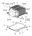
- FIG. 2 is a schematic perspective view of the reactor 1 excluding the case
- FIG. 3 is an exploded perspective view of the reactor 1 excluding the case
- FIG. 4 is an exploded perspective view of the combination 10 provided in the reactor.
- FIG. 5 is an explanatory view of the arrangement of the sensor 9 provided in the reactor.
- the reactor 1 of this embodiment includes an assembly 10 of a coil 2 and a magnetic core 3.
- the reactor 1 further includes a case 8, in which the combined body 10 is housed, and the liquid refrigerant 8L is circulated and supplied into the case 8.
- the combined body 10 is liquid. It is used in a state where it is arranged in the circulation path of the refrigerant 8L.
- the most characteristic feature of the reactor 1 is that at least the surface of the outer core portion 32 exposed from the coil 2 of the magnetic core 3 is composed of a composite material in which soft magnetic powder is dispersed in a resin, and the outer core.
- the outer periphery of the portion 32 is not provided with a covering portion that protects the outer core portion 32 from the liquid refrigerant 8L.
- a covering portion that protects the outer core portion 32 from the liquid refrigerant 8L.
- the coil 2 provided in the combined body 10 shown in FIGS. 2 to 4 includes a pair of coil elements 2A and 2B and a connecting portion 2r that connects both the coil elements 2A and 2B (see particularly FIG. 4).
- the coil elements 2A and 2B are formed in a hollow cylindrical shape with the same number of turns and the same winding direction, and are arranged side by side so that the axial directions are parallel to each other.
- these coil elements 2A and 2B are formed by spirally winding a single winding 2w having no connection portion, and the above-described coupling is achieved by bending the winding in a U-shape.
- Part 2r is formed.
- both the coil elements 2A and 2B may be formed by spirally winding separate windings. In that case, for example, the ends of the coil elements 2A and 2B are joined together by pressure welding or welding. To do.
- a coated wire having an insulating coating made of an insulating material on the outer periphery of a conductor such as a flat wire or a round wire made of a conductive material such as copper, aluminum, or an alloy thereof can be suitably used.
- the conductor is made of a copper rectangular wire
- the insulation coating is made of a coated rectangular wire made of enamel (typically polyamideimide), and each of the coil elements 2A and 2B uses the covered rectangular wire as edgewise. It is a wound edgewise coil.
- the end face shape of each coil element 2A, 2B is made into the shape which rounded the rectangular corner
- Both end portions 2a and 2b (left side of the drawing) of the coil 2 are extended from the turn forming portion and connected to a terminal member (not shown).
- An external device such as a power source for supplying power is connected to the coil 2 through this terminal member.
- the magnetic core 3 provided in the combined body 10 includes a pair of inner core portions 31 and 31 disposed inside the coil elements 2A and 2B, and a pair of outer core portions 32 and 32 exposed from the coil elements 2A and 2B. Is provided.
- the outer core portions 32 and 32 are arranged so as to sandwich the inner core portions 31 and 31 from both sides thereof, and the magnetic core 3 having an annular closed magnetic path is formed by the arrangement.
- the magnetic properties of the entire magnetic core 3 can be adjusted by making the magnetic properties of the inner core portion 31 different from the magnetic properties of the outer core portion 32. For example, if the saturation magnetic flux density of the inner core portion 31> the saturation magnetic flux density of the outer core portion 32, the area of the inner core portion 31 through which the magnetic flux passes can be easily reduced, and the reactor 1 can be reduced in size. If the relative permeability of the inner core portion 31 is less than the relative permeability of the outer core portion 32, the leakage magnetic flux in the outer core portion 32 can be easily reduced because the relative permeability of the outer core portion 32 is relatively high.
- An example of preferable relative permeability and saturation magnetic flux density of the entire magnetic core 3 and the core portions 31 and 32 constituting the magnetic core 3 is shown below.
- relative permeability 10 to 50
- saturation magnetic flux density 0.8 T or more-Inner core part 31
- relative permeability 50 to 500
- saturation magnetic flux density 1.0 T or more-outer core part 32
- Relative permeability 5 or more and 50 or less
- saturation magnetic flux density 0.6T or more
- the outer core portion 32 of the reactor 1 includes, for example, a columnar main body portion 32a having a substantially dome-shaped upper surface and a lower surface, and a pair of flange portions 32b projecting in the width direction of the coil elements 2A and 2B on the lower surface side of the main body portion 32a. And a core piece.
- the main body portion 32a and the flange portion 32b are integrally formed using a composite material described later.
- the main body portion 32 a is a portion that becomes a path for magnetic flux when the reactor 1 is operated.
- the saturation magnetic flux density of the outer core portion 32 is smaller than the saturation magnetic flux density of the inner core portion 31, the area (S OUT ) of the cross section perpendicular to the magnetic path in the outer core portion 32 is It is preferable to make it larger than the area (S IN ) of the cross section orthogonal to the magnetic path in the inner core portion 31.
- the collar part 32b is a part for fixing the union body 10 to the installation object (in this embodiment, the case 8 shown in FIG. 1).
- the flange portion 32b of the present embodiment has a flange shape projecting in the width direction of the coil elements 2A and 2B on the lower surface side of the main body portion 32a.
- a collar made of a rigid material such as metal is embedded in the collar portion 32b, and a bolt used when fixing the combined body 10 to an installation target can be penetrated.
- the collar made of the rigid material receives the tightening force by the bolt and suppresses the damage of the composite material constituting the flange portion 32b.
- the composite material constituting the outer core portion 32 is obtained by dispersing soft magnetic powder in a resin serving as a binder.
- a resin serving as a binder typically, injection molding, transfer molding, MIM (Metal Injection Molding), cast molding, or the like can be used. After filling the molding die with a mixture of magnetic powder and resin and molding, the resin is cured to easily obtain the outer core portion 32 having a desired three-dimensional shape.
- an aggregate of soft magnetic metal particles composed of pure iron, an iron-based alloy, an alloy containing a rare earth element, or the like can be used.
- iron-based alloys include Fe—Si alloys, Fe—Al alloys, Fe—N alloys, Fe—Ni alloys, Fe—C alloys, Fe—B alloys, Fe—Co alloys, Fe— P-based alloys, Fe-Ni-Co-based alloys, Fe-Al-Si, and the like can be given.
- an aggregate of coated particles having an insulating coating on the surface of the soft magnetic particles can be used as the soft magnetic powder. Examples of the insulating coating include a phosphoric acid compound, a silicon compound, a zirconium compound, an aluminum compound, and a boron compound.
- the average particle diameter of the soft magnetic powder is preferably 1 ⁇ m or more and 1000 ⁇ m or less, and particularly preferably 10 ⁇ m or more and 500 ⁇ m or less.
- the soft magnetic powder may be a mixture of a plurality of types of powders having different particle sizes. When a soft magnetic powder having an average particle size satisfying the above range is used as a material, the fluidity is high, and a composite material can be produced with high productivity using injection molding or the like.
- thermosetting resin such as an epoxy resin, a phenol resin, a silicone resin, or a urethane resin
- thermoplastic resins such as polyphenylene sulfide (PPS) resin, polyimide resin, and fluororesin, room temperature curable resin, or low temperature curable resin may be used.
- the content of the soft magnetic powder in the composite material may be 20% by volume or more and 75% by volume or less when the composite material is 100%.
- the ratio of the magnetic component is sufficiently high, so that the saturation magnetic flux density can be easily increased.
- the magnetic powder is 75% by volume or less, the mixture of the magnetic powder and the resin has high fluidity, and a composite material having excellent moldability can be obtained.
- the content of the magnetic powder may be 30% by volume or more, and further 40% by volume or more. Further, the content of the magnetic substance powder is 70% by volume or less, further 65% by volume or less, and 60% by volume or less.
- a composite material containing powder (filler) made of a non-magnetic material such as ceramics such as alumina or silica may be used.
- a filler in the composite material, it is possible to improve heat dissipation of the composite material and to suppress uneven distribution (uniform dispersion) of the magnetic powder in the composite material.
- the filler is finer than the magnetic powder, the decrease in the ratio of the magnetic powder due to the inclusion of the filler can be suppressed.
- the content of the filler is 0.2% by mass or more and 20% by mass or less when the composite material is 100% by mass, the above effect can be sufficiently obtained.
- the above composite material can easily adjust the magnetic properties of the core piece by adjusting the material and content of the magnetic powder, the presence or absence of filler, and the like. That is, it is easy to manufacture a core piece or a magnetic core 3 having desired magnetic characteristics. Further, since the composite material contains a resin, even when the material of the magnetic powder is the same as the material of the particles constituting the green compact, the saturation magnetic flux density tends to be low and the relative permeability tends to be low. It is in.
- the saturation magnetic flux density of the composite material is desirably 0.6 T or more, and more desirably 1.0 T or more. Further, the relative magnetic permeability of the composite material is preferably 5 or more and 50 or less, and more preferably 10 or more and 35 or less.
- the above-mentioned relative permeability and saturation magnetic flux density are measured as follows.
- a ring-shaped test piece having an outer diameter of 34 mm, an inner diameter of 20 mm, and a thickness of 5 mm is produced using the same material as each core piece.
- a BH curve tracer “BHS-40S10K” manufactured by Riken Denshi Co., Ltd. can be used.
- the maximum value of the gradient (B / H) of the obtained BH initial magnetization curve is obtained, and this maximum value is taken as the relative permeability of the core piece.
- the magnetization curve here is a so-called DC magnetization curve.
- the relative permeability here is a so-called DC permeability, which is different from the AC relative permeability measured in an AC magnetic field.
- the saturation magnetic flux density of the core piece is defined as the magnetic flux density when a magnetic field of 10,000 (Oe) is applied to the test piece with an electromagnet and sufficiently magnetically saturated.
- the outer core portion 32 made of the composite material is formed with a surface resin layer containing almost no soft magnetic powder over the entire circumference on the surface side.
- the combined body 10 in the present embodiment is used in a state where it is immersed in the liquid refrigerant 8L in the circulation path of the liquid refrigerant 8L, and thus the outer core portion 32 is exposed to the liquid refrigerant 8L. If the soft magnetic particles contained in the composite material come into contact with the liquid refrigerant 8L, there is a risk of corrosion.
- coated part which protects the outer core part 32 from the liquid refrigerant 8L on the outer periphery of the outer core part 32 is unnecessary.
- the soft magnetic powder settles on the lower side when the outer core portion 32 is molded, and the soft magnetic powder is placed on the outer core portion on the lower side. 32 appears to be exposed on the surface.
- a surface resin layer is formed over the entire circumference of the outer core portion 32, and the soft magnetic powder is hardly exposed on the surface of the outer core portion 32.
- a burr having a shape corresponding to the injection port of the composite material in the mold is formed. Since this burr is usually unnecessary for the outer core portion 32, it is removed, but there is a possibility that the soft magnetic particles are exposed in the removal trace. Therefore, it is preferable to care for the removal mark with a resin or a seal.
- the inner core portions 31, 31 constituting the magnetic core 3 are substantially rectangular parallelepiped magnetic bodies.
- a green compact obtained by compressing soft magnetic powder can be used.
- the inner core part 31 can also be comprised with a composite material, and the laminated body which laminated
- the inner core portion 31 is preferably a powder compact. In the present embodiment, an example in which the inner core portion 31 is a green compact is described.
- the inner core portion 31 using the green compact a laminated body composed of a plurality of rectangular parallelepiped core pieces 31m and gap members 31g interposed between the core pieces 31m, and an outer periphery of the laminated body are covered.
- the inner core part 31 provided with the coating layer 31r can be mentioned.
- the core piece 31m is a powder compact formed by compressing soft magnetic powder
- the gap material 31g is preferably a material having a relative permeability smaller than that of the core piece 31m. Inductance can be adjusted.
- the materials listed in the description of the composite material can be used for the soft magnetic powder used for the green compact.
- the gap material 31g is made of nonmagnetic material such as alumina or unsaturated polyester, nonmagnetic material such as polyphenylene sulfide (PPS) resin, and magnetic material (an example of magnetic material is soft magnetic powder such as iron powder). Mixtures containing it can be used.
- the gap material 31g is composed of the above mixture, the relative permeability of the gap material 31g is preferably 1.05 or more and 2 or less.
- the integration of the core piece 31m and the gap material 31g is easy to handle especially when an adhesive is used, and the core piece 31m is made of a material that vibrates due to magnetostriction, and the gap material 31g is a highly rigid material such as alumina. It is expected that the noise associated with the contact / non-contact between the core piece 31m and the gap material 31g can be reduced even in the case where it is configured.
- an adhesive tape or the like can be used to integrate the core piece 31m and the gap material 31g.
- the core piece 31m and the gap material 31g are integrated by an adhesive.
- the inner core portion 31 is inserted into the coil elements 2A and 2B and is not exposed to the outside of the combined body 10 but is exposed to the liquid refrigerant 8L. Therefore, the coating layer 31r is provided to prevent corrosion of the soft magnetic powder contained in the inner core portion 31 composed of the compacted body, and to prevent the soft magnetic powder from falling off from the inner core portion 31. Is preferred.
- the coating layer 31r also serves as an inner bobbin that secures insulation between the inner core portion 31 and the coil 2. Therefore, the inner bobbin can be omitted by providing the coating layer 31r.
- the coating layer 31r covers a portion excluding the end face 31e of the laminated body of the core piece 31m and the gap material 31g, and suppresses the liquid refrigerant 8L (see FIG. 1) from contacting the core piece 31m.
- an epoxy resin, a urethane resin, a polyimide resin, an amideimide resin, a polyamideimide resin, a silicone resin, a phenol resin, or the like can be used.
- the thickness of the coating layer 31r is 0.1 mm or more and 3 mm or less.
- the thickness of the coating layer 31r By setting the thickness of the coating layer 31r to 0.1 mm or more, the corrosion of the core piece 31m by the liquid refrigerant 8L can be prevented, and the insulation between the inner core portion 31 and the coil 2 can be improved. On the other hand, by setting the thickness of the coating layer 31r to 3 mm or less, the coating layer 31r can be prevented from becoming too thick.
- the coating layer 31r can be formed by immersing the laminated body of the core piece 31m and the gap material 31g in the constituent resin, or by applying the constituent resin to the laminated body with a brush or a spray.
- the green compact forming the core piece 31m can be manufactured by press-molding a soft magnetic powder having an insulating coating on the surface and then appropriately performing a heat treatment.
- a soft magnetic powder having an insulating coating on the surface and then appropriately performing a heat treatment.
- particles such as iron-based materials and rare-earth metals and other soft magnetic materials with insulating coatings on the surfaces of particles and ferrite powders, thermoplastic resins and other additives such as higher fatty acids
- thermoplastic resins and other additives such as higher fatty acids
- the soft magnetic particles are covered with an insulating coating (for example, a phosphoric acid compound, a silicon compound, a zirconium compound, an aluminum compound, a boron compound, etc.), and a compacted body in which an insulator is interposed between the particles. Is obtained.
- the green compact provided with an insulating coating is excellent in insulation and can reduce eddy current loss.
- the average particle diameter of the soft magnetic powder used for the green compact is preferably 1 ⁇ m or more and 1000 ⁇ m or less, particularly preferably 10 ⁇ m or more and 500 ⁇ m or less.
- the soft magnetic powder may be a mixture of a plurality of types of powders having different particle sizes. When a soft magnetic powder obtained by mixing a fine powder and a coarse powder is used as a material for a green compact, a saturated magnetic flux density is high and a low-loss reactor is easily obtained. Note that the size of the soft magnetic powder in the green compact and the powder used for the material are substantially the same (maintained).
- the content of the soft magnetic powder in the green compact is preferably 75% by volume or more and more preferably 80% by volume or more when the green compact is 100%.
- the adjustment of the content of the soft magnetic powder in the green compact is, for example, the thickness of the insulating coating formed on the surface of the soft magnetic particles, or the resin or additive added to the soft magnetic powder during the production of the green compact. Can be adjusted by quantity.
- the magnetic properties of the green compact can be adjusted by changing the content of the soft magnetic powder.
- the magnetic characteristics of the green compact can be adjusted by changing the material of the soft magnetic powder.
- the magnetic characteristics (particularly, the saturation magnetic flux density) of the green compact can be changed by adjusting the molding pressure during pressure molding. In that case, a compacting body with a high saturation magnetic flux density can be obtained by increasing the molding pressure.
- the saturated magnetic flux density of the green compact is preferably 1.0 T or more, more preferably 1.6 T or more, 1.8 T or more, and 2 T or more.
- it is desirable that the relative magnetic permeability of the green compact is 50 or more and 500 or less.
- the heat sink 5 is a plate-like member that supports the combined body 10 and functions as a heat dissipation path for radiating the heat generated in the combined body 10 to the installation target (the mounting surface 81 of the case 8 shown in FIG. 1).
- the installation target the mounting surface 81 of the case 8 shown in FIG. 1.
- one surface side of the heat sink 5 is a mounting surface on which the combined body 10 is mounted, and the other surface side is an attachment surface to an installation target (case 8 in FIG. 1 in this embodiment).
- overhang portions 5 b corresponding to the flange portions 32 b of the outer core portion 32 are provided.
- An insertion hole 51 corresponding to the through hole (collar through hole) of the collar part 32b is formed in the overhang part 5b (see FIG. 3). The insertion hole 51 is used when the assembly 10 is fixed to the installation target.
- the heat radiating plate 5 is disposed close to the coil 2, the heat radiating plate 5 is preferably made of a nonmagnetic material. Moreover, since the heat sink 5 is utilized for the heat dissipation path of the reactor 1, it is preferable to comprise from the metal material which is excellent in heat conductivity. That is, the heat sink 5 is made of aluminum (thermal conductivity: 237 W / m ⁇ K) or an alloy thereof, or nonmagnetic metal such as magnesium (156 W / m ⁇ K) or an alloy thereof. Or you may comprise the heat sink 5 with austenitic stainless steel (for example, SUS304: 16.7 W / m * K).
- austenitic stainless steel for example, SUS304: 16.7 W / m * K.
- the thickness of the heat radiating plate is preferably about 2 mm or more and about 5 mm in consideration of strength and magnetic flux shielding properties.
- the adhesive layer 6 has a function of firmly fixing the combined body 10 to the heat sink 5. Moreover, even if there is a minute unevenness between the bottom surface of the combined body 10 and the top surface (mounting surface) of the radiator plate 5 by the adhesive layer 6, it is difficult to form a gap between them, and as a result, the gap is caused. It is possible to suppress the division of the heat dissipation path.
- the adhesive layer 6 is an insulating resin having an insulation characteristic that can sufficiently insulate the coil 2 and the heat sink 5 and a heat resistance that does not soften against the maximum temperature when the reactor 1 is used. Consists of.
- a thermosetting resin such as an epoxy resin, a silicone resin, or an unsaturated polyester, or a thermoplastic insulating resin such as a PPS resin or a liquid crystal polymer can be suitably used for the adhesive layer.
- the insulating resin may contain at least one ceramic filler selected from silicon nitride, alumina, aluminum nitride, boron nitride, and silicon carbide, so that the insulating properties of the adhesive layer can be increased. And heat dissipation can be improved.
- the thermal conductivity of the adhesive layer is preferably 0.1 W / m ⁇ K or more, more preferably 0.15 W / m ⁇ K or more, still more preferably 0.5 W / m ⁇ K or more, and particularly preferably 1 W. / M ⁇ K or more, most preferably 2.0 W / m ⁇ K or more.
- the thermal conductivity of the adhesive layer 6 is 3 W / m ⁇ K or more.
- the adhesive layer 6 can be formed by coating or screen printing.
- the sensor 9 is arranged in a space (trapezoidal space) surrounded by the coil 2 and the heat sink 5.
- the sensor 9 measures a physical quantity (for example, temperature, current value, voltage value, acceleration, etc.) during operation of the reactor 1.
- the operation of the reactor 1 can be stabilized based on the measurement result.
- movement of the reactor 1 (combination body 10) can be mentioned by utilizing a thermal element such as a thermistor as the sensor 9.
- the space in which the sensor 9 is provided is a place where the temperature tends to be high during the operation of the reactor 1 (combination body 10). Therefore, the operation of the reactor 1 can be stabilized by measuring the temperature of this portion and adjusting the flow rate and temperature of the liquid refrigerant 8L to manage the temperature of the reactor 1 (combined body 10).
- the sensor 9 is fixed by the adhesive layer 6. More specifically, the sensor 9 is embedded in the adhesive layer 6. By adopting such a configuration, the position of the sensor 9 in the space is not shifted due to vibration when the reactor 1 is operated. Therefore, the measurement result by the sensor 9 is less likely to vary. Reliability can be improved. When the reliability of the measurement result is high, the reactor 1 can be operated more stably.
- the reactor 1 of the present embodiment further includes a case 8 that houses the combined body 10, and a circulation path for the liquid refrigerant 8 ⁇ / b> L is formed in the case 8. Yes.
- the liquid refrigerant 8L is not particularly limited, but when the reactor 1 is used in a hybrid vehicle, ATF (Automatic Transmission Fluid) or the like can be used as the liquid refrigerant 8L.
- fluorine-based inert liquids such as Fluorinert (registered trademark), fluorocarbon refrigerants such as HCFC-123 and HFC-134a, alcohol-based refrigerants such as methanol and alcohol, and ketone-based refrigerants such as acetone are used as the liquid refrigerant 8L.
- Fluorinert registered trademark
- fluorocarbon refrigerants such as HCFC-123 and HFC-134a
- alcohol-based refrigerants such as methanol and alcohol
- ketone-based refrigerants such as acetone
- the case 8 is a box-shaped member into which the liquid refrigerant 8L is supplied / discharged, and a supply port (supply part) 80i for supplying the liquid refrigerant 8L into the case 8; And a discharge port (discharge unit) 80o for discharging the liquid refrigerant 8L in the case 8 to the outside of the case 8.
- the liquid refrigerant 8L is supplied into the case 8 from the supply port 80i, and the liquid refrigerant 8L in the case 8 is discharged out of the case 8 through the discharge port 80o.
- the discharged liquid refrigerant 8L is cooled to a predetermined temperature by a cooler (not shown) or the like, and is supplied again from the supply port 80i into the case 8.
- the liquid refrigerant 8L is circulated and supplied into the case 8. That is, the reactor 1 of the first embodiment is used in a state where it is installed at a location where the liquid refrigerant 8L is circulated and supplied.
- the arrangement location and the diameter of the supply port 80i and the discharge port 80o can be selected as appropriate. By appropriately adjusting these, a part of the combined body 10 is immersed in the liquid refrigerant 8L, or the upper surface of the coil 2 is below the liquid surface of the liquid refrigerant 8L as shown in FIG. 1 (the end 2a of the winding 2w is The entire assembly 10 may be constantly immersed in the liquid refrigerant 8L so as to be positioned on the liquid surface.
- the supply port 80i is provided above the combined body 10
- the discharge port 80o is provided at a position substantially the same as the height of the fixing portion 82 described later.
- the diameter ⁇ o of the discharge port 80 o is made smaller than the diameter ⁇ i of the supply port 80 i . Thereby, as shown in FIG. 1, the whole assembly 10 is always immersed in the liquid refrigerant 8L.
- the case 8 includes a mounting surface 81 facing the heat radiating plate 5 and a fixing portion 82 for fixing the heat radiating plate 5.
- the fixed portion 82 protrudes from the mounting surface 81 of the case 8 so that the liquid refrigerant 8L flows between the mounting surface 81 of the case 8 and the heat radiating plate 5.
- the height of the fixing portion 82 is set such that the liquid refrigerant can sufficiently flow under the heat radiating plate 5. By doing so, the heat dissipation of the reactor 1 can be improved more.
- the space for allowing the liquid refrigerant 8L to flow between the heat radiating plate 5 and the mounting surface 81 can be formed by the fixing portion 82, and the liquid refrigerant 8L can be brought into direct contact with the lower surface of the heat radiating plate 5.
- the number of the fixing portions 82 is the same as the number of the insertion holes 51 of the heat radiating plate 5, and the arrangement portion of the fixing portions 82 is a portion corresponding to the insertion hole 51 (see FIG. 3) of the heat radiating plate 5. It is done.
- An insertion hole through which a bolt 51 b for fixing the heat radiating plate 5 is inserted is formed on the contact surface of the fixing portion 82 with the heat radiating plate 5.
- the insertion hole is internally threaded, and the assembly 10 including the heat sink 5 is fixed to the case 8 by screwing a bolt 51b into the insertion hole.
- Examples of the material of the case 8 include metals such as aluminum and alloys thereof, magnesium and alloys thereof, copper and alloys thereof, silver and alloys thereof, iron and austenitic stainless steel.
- aluminum, magnesium, and alloys thereof are lightweight and can be expected to have a shielding function.
- Aluminum and its alloys are also excellent in heat dissipation.
- examples of the material of the case 8 include insulating resins such as PBT (polybutylene terephthalate) resin, urethane resin, PPS resin, and ABS (acrylonitrile-butadiene-styrene) resin. These insulating resins may contain ceramic fillers such as silicon nitride, alumina, aluminum nitride, boron nitride, mullite, and silicon carbide.
- Embodiment 1 According to the structure of Embodiment 1 demonstrated above, even if it is the reactor 1 used in the state installed in the location where the liquid refrigerant 8L is circulated and supplied, it is excellent in productivity. That is, the outer core portion 32 provided in the combination 10 of the reactor 1 is made of a composite material, and it is not necessary to provide a covering portion for protecting the outer core portion 32 from the liquid refrigerant 8L on the outer periphery of the outer core portion 32. Because.
- Embodiment 2 demonstrates the structure which provided the thermal radiation part 32c in the outer core part 32 based on FIG.
- the outer core portion 32 is made of a composite material. Since the composite material is extremely excellent in moldability, the outer core portion 32 having any shape can be manufactured as long as the mold is manufactured. Therefore, as shown in FIG. 6, in the outer core portion 32, it is preferable to form a heat radiating portion 32c protruding from the outer periphery of the main body portion 32a. By providing the heat radiating part 32 c, the heat dissipation through the outer core part 32 can be improved.
- the heat radiation part 32c is preferably provided integrally with the main body part 32a using a composite material. That is, when forming the outer core portion 32 using a composite material, a portion corresponding to the heat radiating portion 32c is formed in a mold for molding the outer core portion 32, and the main body portion 32a, the heat radiating portion 32c, and the flange portion 32b are formed. It is better to mold the
- the shape of the heat radiation part 32c is not particularly limited. Typically, the fin-shaped heat radiation part 32c shown in FIG. 6 is formed. By making the heat radiation part 32c into a fin shape, the heat radiation effect by the heat radiation part 32c can be improved.
- the heat radiating part 32c is preferably immersed in the liquid refrigerant 8L in the case 8 shown in FIG. 1, and further improvement of the heat radiating effect by the heat radiating part 32c can be expected.
- the protruding end of the fin-shaped heat radiation portion 32c shown in FIG. 6 can be used as a composite material injection port in the mold. In that case, unnecessary burrs are unlikely to occur in the outer core portion 32.
- Reactors 1 described in the first and second embodiments are used in which the energization conditions are, for example, maximum current (direct current): about 100 A to 1000 A, average voltage: about 100 V to 1000 V, and operating frequency: about 5 kHz to 100 kHz.
- the energization conditions are, for example, maximum current (direct current): about 100 A to 1000 A, average voltage: about 100 V to 1000 V, and operating frequency: about 5 kHz to 100 kHz.
- it can be suitably used as a component part of an in-vehicle power conversion device such as an electric vehicle or a hybrid vehicle.
- an inductance satisfying 10 ⁇ H or more and 2 mH or less of the inductance when the DC current is 0 A and 10% or more of the inductance when the maximum current is applied is 10% or more can be suitably used.
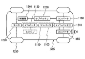
- the reactor 1 is used as a component part of a power conversion device mounted on a vehicle such as a hybrid vehicle or an electric vehicle will be described with reference to FIGS.
- a vehicle 1200 such as a hybrid vehicle or an electric vehicle is driven for driving by being driven by a main battery 1210, a power converter 1100 connected to the main battery 1210, and power supplied from the main battery 1210 as shown in FIG.
- the motor (load) 1220 is provided.
- the motor 1220 is typically a three-phase AC motor, which drives the wheel 1250 when traveling and functions as a generator during regeneration.
- vehicle 1200 includes an engine in addition to motor 1220.
- an inlet is shown as a charge location of the vehicle 1200, it is good also as a form provided with a plug.
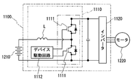
- the power conversion device 1100 includes a converter 1110 connected to the main battery 1210 and an inverter 1120 connected to the converter 1110 and performing mutual conversion between direct current and alternating current.
- the converter 1110 shown in this example boosts the DC voltage (input voltage) of the main battery 1210 of about 200V to 300V to about 400V to 700V when the vehicle 1200 is running, and supplies the inverter 1120 with power.
- converter 1110 steps down DC voltage (input voltage) output from motor 1220 via inverter 1120 to DC voltage suitable for main battery 1210 during regeneration, and causes main battery 1210 to be charged.
- the inverter 1120 converts the direct current boosted by the converter 1110 into a predetermined alternating current when the vehicle 1200 is running, and supplies the motor 1220 with electric power. During regeneration, the alternating current output from the motor 1220 is converted into direct current and output to the converter 1110. is doing.
- the converter 1110 includes a plurality of switching elements 1111, a drive circuit 1112 that controls the operation of the switching elements 1111, and a reactor L, and converts input voltage by ON / OFF repetition (switching operation). (In this case, step-up / down pressure) is performed.
- a power device such as FET or IGBT is used.
- the reactor L has the function of smoothing the change when the current is going to increase or decrease by the switching operation by utilizing the property of the coil that prevents the change of the current to flow through the circuit.
- the reactor L the reactor described in the above embodiment is used.
- the vehicle 1200 is connected to the converter 1110, the power supply converter 1150 connected to the main battery 1210, and the sub-battery 1230 and the main battery 1210 that are power sources of the auxiliary devices 1240.
- Auxiliary power supply converter 1160 for converting the high voltage 1210 to a low voltage is provided.
- the converter 1110 typically performs DC-DC conversion, while the power supply device converter 1150 and the auxiliary power supply converter 1160 perform AC-DC conversion. Some power supply device converters 1150 perform DC-DC conversion.
- the reactors of the power supply device converter 1150 and the auxiliary power supply converter 1160 have the same configuration as the reactors of the above-described embodiments and modifications, and a reactor whose size and shape are appropriately changed can be used.
- the reactor of the above-described embodiment can be used for a converter that performs conversion of input power and that only performs step-up or converter that performs only step-down.
- the reactor of the present invention can be used as a component part of a power conversion device such as a bidirectional DC-DC converter mounted on a vehicle such as a hybrid vehicle, an electric vehicle, or a fuel cell vehicle.
- a power conversion device such as a bidirectional DC-DC converter mounted on a vehicle such as a hybrid vehicle, an electric vehicle, or a fuel cell vehicle.
Landscapes
- Engineering & Computer Science (AREA)
- Power Engineering (AREA)
- Coils Of Transformers For General Uses (AREA)
- Transformer Cooling (AREA)
- Dc-Dc Converters (AREA)
Abstract
La présente invention concerne un réacteur à utiliser dans un état dans lequel il est disposé dans le trajet de circulation d'un réfrigérant à l'état liquide et que l'on peut produire à des rendements supérieurs. Le réacteur est pourvu d'un ensemble comprenant : une bobine issue de l'enroulement d'un fil; et des noyaux magnétiques disposés à l'intérieur et à l'extérieur de la bobine, formant un circuit magnétique fermé. Le réacteur est utilisé dans un état dans lequel l'ensemble est installé à une position à laquelle est délivré un réfrigérant à l'état liquide. Dans le réacteur, les noyaux magnétiques possèdent des parties de noyau interne disposées à l'intérieur de la bobine et des parties de noyau externe disposées au-delà de la bobine, les parties de noyau externe en contact avec le réfrigérant à l'état liquide étant constituées d'un matériau composite comprenant une poudre magnétique tendre dispersée dans une résine.
Applications Claiming Priority (2)
| Application Number | Priority Date | Filing Date | Title |
|---|---|---|---|
| JP2013136614A JP6080110B2 (ja) | 2013-06-28 | 2013-06-28 | リアクトル |
| JP2013-136614 | 2013-06-28 |
Publications (1)
| Publication Number | Publication Date |
|---|---|
| WO2014208317A1 true WO2014208317A1 (fr) | 2014-12-31 |
Family
ID=52141663
Family Applications (1)
| Application Number | Title | Priority Date | Filing Date |
|---|---|---|---|
| PCT/JP2014/065187 WO2014208317A1 (fr) | 2013-06-28 | 2014-06-09 | Réacteur |
Country Status (2)
| Country | Link |
|---|---|
| JP (1) | JP6080110B2 (fr) |
| WO (1) | WO2014208317A1 (fr) |
Cited By (2)
| Publication number | Priority date | Publication date | Assignee | Title |
|---|---|---|---|---|
| WO2016136680A1 (fr) * | 2015-02-27 | 2016-09-01 | 株式会社オートネットワーク技術研究所 | Réacteur |
| WO2016204188A1 (fr) * | 2015-06-19 | 2016-12-22 | 北川工業株式会社 | Élément de suppression de bruit |
Families Citing this family (2)
| Publication number | Priority date | Publication date | Assignee | Title |
|---|---|---|---|---|
| JP6478108B2 (ja) * | 2015-04-03 | 2019-03-06 | 株式会社オートネットワーク技術研究所 | リアクトル |
| WO2018142666A1 (fr) | 2017-01-31 | 2018-08-09 | アルプス電気株式会社 | Noyau compact en poudre, procédé de fabrication de noyau compact en poudre, composant électrique/électronique comportant un noyau compact en poudre, et appareil électrique/électronique dans lequel est monté un composant électrique/électronique |
Citations (10)
| Publication number | Priority date | Publication date | Assignee | Title |
|---|---|---|---|---|
| JPH06302444A (ja) * | 1993-04-19 | 1994-10-28 | Mitsubishi Electric Corp | リアクトル内蔵式車両用主変圧器 |
| JP2002008923A (ja) * | 2000-06-21 | 2002-01-11 | Sansei Sangyo Kk | 高周波トランス |
| JP2006114828A (ja) * | 2004-10-18 | 2006-04-27 | Tabuchi Electric Co Ltd | 電磁誘導器 |
| JP2007335833A (ja) * | 2006-05-16 | 2007-12-27 | Denso Corp | リアクトル及びこれを内蔵した電力変換装置 |
| JP2008028308A (ja) * | 2006-07-25 | 2008-02-07 | Sumitomo Electric Ind Ltd | 車載用リアクトル |
| JP2009049082A (ja) * | 2007-08-15 | 2009-03-05 | Toyota Motor Corp | リアクトル冷却システム |
| JP2011129593A (ja) * | 2009-12-15 | 2011-06-30 | Sumitomo Electric Ind Ltd | リアクトル |
| JP2011228547A (ja) * | 2010-04-21 | 2011-11-10 | Toyota Industries Corp | リアクトルの冷却構造 |
| WO2012147644A1 (fr) * | 2011-04-28 | 2012-11-01 | 住友電気工業株式会社 | Réacteur, matériau composite, cœur de réacteur, convertisseur et dispositif de conversion de l'énergie |
| WO2014069311A1 (fr) * | 2012-11-01 | 2014-05-08 | 株式会社オートネットワーク技術研究所 | Réactance, convertisseur et dispositif de conversion de puissance |
-
2013
- 2013-06-28 JP JP2013136614A patent/JP6080110B2/ja not_active Expired - Fee Related
-
2014
- 2014-06-09 WO PCT/JP2014/065187 patent/WO2014208317A1/fr active Application Filing
Patent Citations (10)
| Publication number | Priority date | Publication date | Assignee | Title |
|---|---|---|---|---|
| JPH06302444A (ja) * | 1993-04-19 | 1994-10-28 | Mitsubishi Electric Corp | リアクトル内蔵式車両用主変圧器 |
| JP2002008923A (ja) * | 2000-06-21 | 2002-01-11 | Sansei Sangyo Kk | 高周波トランス |
| JP2006114828A (ja) * | 2004-10-18 | 2006-04-27 | Tabuchi Electric Co Ltd | 電磁誘導器 |
| JP2007335833A (ja) * | 2006-05-16 | 2007-12-27 | Denso Corp | リアクトル及びこれを内蔵した電力変換装置 |
| JP2008028308A (ja) * | 2006-07-25 | 2008-02-07 | Sumitomo Electric Ind Ltd | 車載用リアクトル |
| JP2009049082A (ja) * | 2007-08-15 | 2009-03-05 | Toyota Motor Corp | リアクトル冷却システム |
| JP2011129593A (ja) * | 2009-12-15 | 2011-06-30 | Sumitomo Electric Ind Ltd | リアクトル |
| JP2011228547A (ja) * | 2010-04-21 | 2011-11-10 | Toyota Industries Corp | リアクトルの冷却構造 |
| WO2012147644A1 (fr) * | 2011-04-28 | 2012-11-01 | 住友電気工業株式会社 | Réacteur, matériau composite, cœur de réacteur, convertisseur et dispositif de conversion de l'énergie |
| WO2014069311A1 (fr) * | 2012-11-01 | 2014-05-08 | 株式会社オートネットワーク技術研究所 | Réactance, convertisseur et dispositif de conversion de puissance |
Cited By (6)
| Publication number | Priority date | Publication date | Assignee | Title |
|---|---|---|---|---|
| WO2016136680A1 (fr) * | 2015-02-27 | 2016-09-01 | 株式会社オートネットワーク技術研究所 | Réacteur |
| JP2016162859A (ja) * | 2015-02-27 | 2016-09-05 | 株式会社オートネットワーク技術研究所 | リアクトル |
| CN107408450A (zh) * | 2015-02-27 | 2017-11-28 | 株式会社自动网络技术研究所 | 电抗器 |
| WO2016204188A1 (fr) * | 2015-06-19 | 2016-12-22 | 北川工業株式会社 | Élément de suppression de bruit |
| JP2017011061A (ja) * | 2015-06-19 | 2017-01-12 | 北川工業株式会社 | ノイズ対策部材 |
| US10381150B2 (en) | 2015-06-19 | 2019-08-13 | Kitagawa Industries Co., Ltd. | Noise suppression member |
Also Published As
| Publication number | Publication date |
|---|---|
| JP6080110B2 (ja) | 2017-02-15 |
| JP2015012146A (ja) | 2015-01-19 |
Similar Documents
| Publication | Publication Date | Title |
|---|---|---|
| JP6176516B2 (ja) | リアクトル、コンバータ、及び電力変換装置 | |
| JP6065609B2 (ja) | リアクトル、コンバータ、及び電力変換装置 | |
| JP6098786B2 (ja) | 複合材料、リアクトル、コンバータ、及び電力変換装置 | |
| JP5867677B2 (ja) | リアクトル、コンバータ及び電力変換装置 | |
| JP6127365B2 (ja) | リアクトル、複合材料、リアクトル用コア、コンバータ、及び電力変換装置 | |
| JP5991460B2 (ja) | 複合材料、リアクトル用コア、及びリアクトル | |
| JP5983942B2 (ja) | リアクトル、コンバータ、及び電力変換装置 | |
| JP5995181B2 (ja) | 複合材料、リアクトル用コア、及びリアクトル | |
| JP6048652B2 (ja) | リアクトル、コンバータ、および電力変換装置 | |
| JP6032551B2 (ja) | リアクトル、コンバータ、及び電力変換装置 | |
| JP2015012147A (ja) | リアクトル | |
| JP6080110B2 (ja) | リアクトル | |
| JP7367564B2 (ja) | リアクトル、コンバータ、及び電力変換装置 | |
| JP5945906B2 (ja) | リアクトルの収納構造体、および電力変換装置 | |
| JP2013162069A (ja) | リアクトル、コンバータ、及び電力変換装置 | |
| JP2013179186A (ja) | リアクトル、リアクトル用部品、コンバータ、及び電力変換装置 | |
| WO2013168538A1 (fr) | Réacteur, convertisseur, dispositif de conversion d'énergie électrique et méthode de fabrication de pièce de noyau en résine | |
| JP6226047B2 (ja) | 複合材料、リアクトル用コア、及びリアクトル | |
| JP2017017326A (ja) | 複合材料、リアクトル用コア、及びリアクトル | |
| JP2015012145A (ja) | リアクトル | |
| JP2015126145A (ja) | リアクトル | |
| US8618899B2 (en) | Converter and power conversion device | |
| JP6016035B2 (ja) | リアクトル | |
| JP2013074063A (ja) | リアクトル | |
| JP2023032528A (ja) | リアクトル、コンバータ、及び電力変換装置 |
Legal Events
| Date | Code | Title | Description |
|---|---|---|---|
| 121 | Ep: the epo has been informed by wipo that ep was designated in this application |
Ref document number: 14818554 Country of ref document: EP Kind code of ref document: A1 |
|
| NENP | Non-entry into the national phase |
Ref country code: DE |
|
| 122 | Ep: pct application non-entry in european phase |
Ref document number: 14818554 Country of ref document: EP Kind code of ref document: A1 |