WO2012144302A1 - 車両用駆動装置 - Google Patents
車両用駆動装置 Download PDFInfo
- Publication number
- WO2012144302A1 WO2012144302A1 PCT/JP2012/058179 JP2012058179W WO2012144302A1 WO 2012144302 A1 WO2012144302 A1 WO 2012144302A1 JP 2012058179 W JP2012058179 W JP 2012058179W WO 2012144302 A1 WO2012144302 A1 WO 2012144302A1
- Authority
- WO
- WIPO (PCT)
- Prior art keywords
- electrical machine
- rotating electrical
- internal combustion
- combustion engine
- torque
- Prior art date
- Legal status (The legal status is an assumption and is not a legal conclusion. Google has not performed a legal analysis and makes no representation as to the accuracy of the status listed.)
- Ceased
Links
Images


Classifications
-
- B—PERFORMING OPERATIONS; TRANSPORTING
- B60—VEHICLES IN GENERAL
- B60W—CONJOINT CONTROL OF VEHICLE SUB-UNITS OF DIFFERENT TYPE OR DIFFERENT FUNCTION; CONTROL SYSTEMS SPECIALLY ADAPTED FOR HYBRID VEHICLES; ROAD VEHICLE DRIVE CONTROL SYSTEMS FOR PURPOSES NOT RELATED TO THE CONTROL OF A PARTICULAR SUB-UNIT
- B60W10/00—Conjoint control of vehicle sub-units of different type or different function
- B60W10/02—Conjoint control of vehicle sub-units of different type or different function including control of driveline clutches
-
- B—PERFORMING OPERATIONS; TRANSPORTING
- B60—VEHICLES IN GENERAL
- B60K—ARRANGEMENT OR MOUNTING OF PROPULSION UNITS OR OF TRANSMISSIONS IN VEHICLES; ARRANGEMENT OR MOUNTING OF PLURAL DIVERSE PRIME-MOVERS IN VEHICLES; AUXILIARY DRIVES FOR VEHICLES; INSTRUMENTATION OR DASHBOARDS FOR VEHICLES; ARRANGEMENTS IN CONNECTION WITH COOLING, AIR INTAKE, GAS EXHAUST OR FUEL SUPPLY OF PROPULSION UNITS IN VEHICLES
- B60K6/00—Arrangement or mounting of plural diverse prime-movers for mutual or common propulsion, e.g. hybrid propulsion systems comprising electric motors and internal combustion engines
- B60K6/20—Arrangement or mounting of plural diverse prime-movers for mutual or common propulsion, e.g. hybrid propulsion systems comprising electric motors and internal combustion engines the prime-movers consisting of electric motors and internal combustion engines, e.g. HEVs
- B60K6/22—Arrangement or mounting of plural diverse prime-movers for mutual or common propulsion, e.g. hybrid propulsion systems comprising electric motors and internal combustion engines the prime-movers consisting of electric motors and internal combustion engines, e.g. HEVs characterised by apparatus, components or means specially adapted for HEVs
- B60K6/38—Arrangement or mounting of plural diverse prime-movers for mutual or common propulsion, e.g. hybrid propulsion systems comprising electric motors and internal combustion engines the prime-movers consisting of electric motors and internal combustion engines, e.g. HEVs characterised by apparatus, components or means specially adapted for HEVs characterised by the driveline clutches
- B60K6/387—Actuated clutches, i.e. clutches engaged or disengaged by electric, hydraulic or mechanical actuating means
-
- B—PERFORMING OPERATIONS; TRANSPORTING
- B60—VEHICLES IN GENERAL
- B60K—ARRANGEMENT OR MOUNTING OF PROPULSION UNITS OR OF TRANSMISSIONS IN VEHICLES; ARRANGEMENT OR MOUNTING OF PLURAL DIVERSE PRIME-MOVERS IN VEHICLES; AUXILIARY DRIVES FOR VEHICLES; INSTRUMENTATION OR DASHBOARDS FOR VEHICLES; ARRANGEMENTS IN CONNECTION WITH COOLING, AIR INTAKE, GAS EXHAUST OR FUEL SUPPLY OF PROPULSION UNITS IN VEHICLES
- B60K6/00—Arrangement or mounting of plural diverse prime-movers for mutual or common propulsion, e.g. hybrid propulsion systems comprising electric motors and internal combustion engines
- B60K6/20—Arrangement or mounting of plural diverse prime-movers for mutual or common propulsion, e.g. hybrid propulsion systems comprising electric motors and internal combustion engines the prime-movers consisting of electric motors and internal combustion engines, e.g. HEVs
- B60K6/42—Arrangement or mounting of plural diverse prime-movers for mutual or common propulsion, e.g. hybrid propulsion systems comprising electric motors and internal combustion engines the prime-movers consisting of electric motors and internal combustion engines, e.g. HEVs characterised by the architecture of the hybrid electric vehicle
- B60K6/44—Series-parallel type
- B60K6/445—Differential gearing distribution type
-
- B—PERFORMING OPERATIONS; TRANSPORTING
- B60—VEHICLES IN GENERAL
- B60W—CONJOINT CONTROL OF VEHICLE SUB-UNITS OF DIFFERENT TYPE OR DIFFERENT FUNCTION; CONTROL SYSTEMS SPECIALLY ADAPTED FOR HYBRID VEHICLES; ROAD VEHICLE DRIVE CONTROL SYSTEMS FOR PURPOSES NOT RELATED TO THE CONTROL OF A PARTICULAR SUB-UNIT
- B60W10/00—Conjoint control of vehicle sub-units of different type or different function
- B60W10/04—Conjoint control of vehicle sub-units of different type or different function including control of propulsion units
- B60W10/08—Conjoint control of vehicle sub-units of different type or different function including control of propulsion units including control of electric propulsion units, e.g. motors or generators
-
- B—PERFORMING OPERATIONS; TRANSPORTING
- B60—VEHICLES IN GENERAL
- B60W—CONJOINT CONTROL OF VEHICLE SUB-UNITS OF DIFFERENT TYPE OR DIFFERENT FUNCTION; CONTROL SYSTEMS SPECIALLY ADAPTED FOR HYBRID VEHICLES; ROAD VEHICLE DRIVE CONTROL SYSTEMS FOR PURPOSES NOT RELATED TO THE CONTROL OF A PARTICULAR SUB-UNIT
- B60W20/00—Control systems specially adapted for hybrid vehicles
- B60W20/40—Controlling the engagement or disengagement of prime movers, e.g. for transition between prime movers
-
- F—MECHANICAL ENGINEERING; LIGHTING; HEATING; WEAPONS; BLASTING
- F02—COMBUSTION ENGINES; HOT-GAS OR COMBUSTION-PRODUCT ENGINE PLANTS
- F02D—CONTROLLING COMBUSTION ENGINES
- F02D29/00—Controlling engines, such controlling being peculiar to the devices driven thereby, the devices being other than parts or accessories essential to engine operation, e.g. controlling of engines by signals external thereto
- F02D29/02—Controlling engines, such controlling being peculiar to the devices driven thereby, the devices being other than parts or accessories essential to engine operation, e.g. controlling of engines by signals external thereto peculiar to engines driving vehicles; peculiar to engines driving variable pitch propellers
-
- B—PERFORMING OPERATIONS; TRANSPORTING
- B60—VEHICLES IN GENERAL
- B60W—CONJOINT CONTROL OF VEHICLE SUB-UNITS OF DIFFERENT TYPE OR DIFFERENT FUNCTION; CONTROL SYSTEMS SPECIALLY ADAPTED FOR HYBRID VEHICLES; ROAD VEHICLE DRIVE CONTROL SYSTEMS FOR PURPOSES NOT RELATED TO THE CONTROL OF A PARTICULAR SUB-UNIT
- B60W2710/00—Output or target parameters relating to a particular sub-units
- B60W2710/02—Clutches
- B60W2710/025—Clutch slip, i.e. difference between input and output speeds
-
- B—PERFORMING OPERATIONS; TRANSPORTING
- B60—VEHICLES IN GENERAL
- B60W—CONJOINT CONTROL OF VEHICLE SUB-UNITS OF DIFFERENT TYPE OR DIFFERENT FUNCTION; CONTROL SYSTEMS SPECIALLY ADAPTED FOR HYBRID VEHICLES; ROAD VEHICLE DRIVE CONTROL SYSTEMS FOR PURPOSES NOT RELATED TO THE CONTROL OF A PARTICULAR SUB-UNIT
- B60W2710/00—Output or target parameters relating to a particular sub-units
- B60W2710/08—Electric propulsion units
- B60W2710/081—Speed
-
- Y—GENERAL TAGGING OF NEW TECHNOLOGICAL DEVELOPMENTS; GENERAL TAGGING OF CROSS-SECTIONAL TECHNOLOGIES SPANNING OVER SEVERAL SECTIONS OF THE IPC; TECHNICAL SUBJECTS COVERED BY FORMER USPC CROSS-REFERENCE ART COLLECTIONS [XRACs] AND DIGESTS
- Y02—TECHNOLOGIES OR APPLICATIONS FOR MITIGATION OR ADAPTATION AGAINST CLIMATE CHANGE
- Y02T—CLIMATE CHANGE MITIGATION TECHNOLOGIES RELATED TO TRANSPORTATION
- Y02T10/00—Road transport of goods or passengers
- Y02T10/60—Other road transportation technologies with climate change mitigation effect
- Y02T10/62—Hybrid vehicles
Definitions
- the present invention includes an input member that is drivingly connected to the internal combustion engine, an output member that is drivingly connected to the wheels, an intermediate member that is drivingly connected to the rotating electrical machine in a power transmission path that connects the input member and the output member,
- the present invention relates to a vehicle drive device including a friction engagement device capable of releasing a drive connection between an input member and an intermediate member, and a control device.
- Patent Document 1 As a conventional technique of the vehicle drive device as described above, for example, there is a technique described in Patent Document 1 below.
- the device of Patent Document 1 includes a differential having three rotating elements: a sun gear that is drivingly connected to the first rotating electrical machine, a carrier that is drivingly connected to the intermediate member, a ring gear that is drivingly connected to the second rotating electrical machine and the output member.
- a gear device is further provided.
- this device has an electric travel mode in which the vehicle is driven by the torque of the second rotating electrical machine in a stopped state of the internal combustion engine, and a split that travels the vehicle by distributing the torque of the internal combustion engine to the first rotating electrical machine and the output member.
- a travel mode (a kind of hybrid travel mode).
- a friction engagement device for separating an internal combustion engine from a wheel is provided between an intermediate member and an input member drivingly connected to the internal combustion engine in order to improve energy efficiency during traveling in the electric traveling mode. It is provided in between. Then, when switching from the electric travel mode to the split travel mode, the rotational speed of the first rotating electrical machine is controlled so that the differential rotational speed between the engagement members on both sides of the friction engagement device is zero, and the synchronous engagement is performed. Thereafter, the rotational speed of the first rotating electrical machine is increased to start the internal combustion engine. As a result, it is possible to suppress the occurrence of a shock when the friction engagement device is engaged, and to maintain the durability of the friction material well.
- the rotational speed of the rotating member (here, the input member) connected to the engaging member on one side of the friction engagement device is zero.
- the rotational speed of the rotating member (here, the intermediate member) connected to the other engaging member becomes zero.
- the rotating members on both sides of the frictional engagement device may be eccentric from each other without the function of adjusting the shaft center by their own rotation, depending on their shaft support structures. If the friction engagement device is engaged in such an eccentric state to be in a direct engagement state, the rotating members on both sides of the friction engagement device are engaged in an eccentric state. And if driving
- JP 2010-76678 A paragraphs 0075, 0076, etc.
- an input member that is drivingly connected to an internal combustion engine, an output member that is drivingly connected to a wheel, and a power transmission path that connects the input member and the output member and is intermediately connected to a rotating electrical machine
- the vehicle drive device comprising: a member, a friction engagement device capable of releasing the drive connection between the input member and the intermediate member, and a control device.
- a synchronous engagement control unit that engages the friction engagement device to bring it into a direct engagement state, and the rotational speed of the input member is increased by the torque of the rotating electrical machine in the direct engagement state of the friction engagement device.
- a starting system for starting the internal combustion engine And when the internal combustion engine is in a rotational state where the rotational speed of the internal combustion engine is equal to or greater than a predetermined value, the engagement pressure of the friction engagement device is decreased and it is detected that the differential rotational speed is equal to or greater than the differential rotation threshold.
- a centering control unit that performs a centering operation for returning the friction engagement device to the direct connection state.
- driving connection refers to a state where two rotating elements are connected so as to be able to transmit a driving force, and the two rotating elements are connected so as to rotate integrally, or the two
- the rotating element is used as a concept including a state in which the driving force is connected to be transmitted through one or more transmission members.
- a transmission member include various members that transmit rotation at the same speed or a variable speed, and include, for example, a shaft, a gear mechanism, a belt, a chain, and the like.
- an engagement element that selectively transmits rotation and driving force for example, a friction engagement element, a meshing engagement element, or the like may be included.
- the “rotary electric machine” is used as a concept including a motor (electric motor), a generator (generator), and a motor / generator functioning as both a motor and a generator as necessary.
- the “directly engaged state” means a state in which the engagement members on both sides of the friction engagement device are engaged with each other, and the “released state” is a rotation between the engagement members on both sides. And a state where torque is not transmitted.
- the friction engagement device when the internal combustion engine start condition is satisfied, the friction engagement device is engaged in a synchronized state where the differential rotation speed between the input member and the intermediate member is equal to or less than a predetermined value. It is possible to suppress the occurrence of shock when the friction engagement device is engaged.
- both the input member and the intermediate member on both sides of the friction engagement device have a rotational speed of zero and are eccentric with each other. It can become a state.
- the engagement pressure of the friction engagement device is reduced to temporarily apply the restraining force due to the engagement pressure.
- the friction engagement device is returned to the direct engagement state again after detecting that a predetermined differential rotational speed has occurred between the input member and the intermediate member.
- the alignment control unit performs the alignment operation after the torque of the internal combustion engine becomes equal to or greater than a predetermined value.
- the aligning operation can be performed in a state where the internal combustion engine is operating independently, and the input member and the intermediate member on both sides of the friction engagement device are utilized by utilizing the rotation and torque of the internal combustion engine. It is possible to appropriately prevent the eccentric state from continuing.
- control device further includes a rotating electrical machine control unit that instructs the rotating electrical machine to set a target rotational speed when starting the internal combustion engine, and performs rotational speed control to match the rotational speed of the rotating electrical machine with the target rotational speed.
- the alignment control unit detects the time of torque reversal in which the direction of torque of the rotating electrical machine is reversed while the rotational speed control of the rotating electrical machine is being executed, and simultaneously performs the alignment at the time of detection of the torque reversal. It is preferable that the operation is started.
- the rotating electrical machine When the internal combustion engine is started by the torque of the rotating electrical machine, the torque of the internal combustion engine is transmitted to the rotating electrical machine. At this time, the rotational speed of the rotating electrical machine tends to increase or decrease according to the drive connection relationship between the internal combustion engine and the rotating electrical machine.
- the rotating electrical machine since the rotating electrical machine is controlled in rotational speed, the rotating electrical machine has a torque in a direction opposite to that at the start of the internal combustion engine so that the rotational speed of the rotating electrical machine matches a predetermined target rotational speed. Is output. That is, the direction of torque of the rotating electrical machine is reversed before and after the internal combustion engine is started.
- a differential gear device having a first rotating element, a second rotating element, and a third rotating element in order of rotational speed is provided, and the first rotation is performed without any other rotating element of the differential gear device.
- the rotating electrical machine is drivingly connected to an element
- the intermediate member is drivingly connected to the second rotating element
- the output member is drivingly connected to the third rotating element
- the control device includes the rotating electrical machine and the internal combustion engine
- the torque control unit further outputs a torque maintenance command for commanding the torque to be maintained at a constant value that does not change with time
- the alignment control unit includes the rotating electrical machine and the internal combustion engine. It is preferable to perform the alignment operation in a state where both torques are maintained at a constant value.
- a differential gear mechanism including three rotating elements such as a planetary gear mechanism including a sun gear, a carrier, and a ring gear is used, and the differential gear mechanism alone or a plurality of differential gear mechanisms are combined.
- the resulting device is called a “differential gear device”.
- the "rotation speed order" is either the order from the high speed side to the low speed side or the order from the low speed side to the high speed side, and can be either depending on the rotation state of each differential gear mechanism.
- the order of the rotating elements does not change. That is, “in order of rotational speed” means “in order of increasing or decreasing rotational speed in the rotational state of each rotating element”.
- the “order of rotational speed” is the same as the order of arrangement in the speed diagram (collinear diagram) of each rotating element.
- “arrangement order of speed elements in the speed diagram (collinear diagram)” is the order in which the axes corresponding to the respective speed elements are arranged in the speed diagram.
- the torque transmitted through the friction engagement device by reducing the engagement pressure of the friction engagement device in a state where the torques of both the rotating electrical machine and the internal combustion engine are maintained at constant values.
- the rotational speed of the rotating electrical machine changes due to the torque of the rotating electrical machine. Therefore, by detecting an event that the rotational speed of the rotating electrical machine changes, it is possible to appropriately detect that the differential rotational speed between the input member and the intermediate member is equal to or greater than the differential rotational threshold. Therefore, it is possible to easily determine the end of the alignment operation.
- a differential gear device having a first rotating element, a second rotating element, and a third rotating element, and a second rotating electrical machine in order of rotational speed, and the second rotating electric machine,
- the rotating electric machine is drivingly connected to the first rotating element
- the intermediate member is drivingly connected to the second rotating element
- the output member and the second rotating electric machine are drivingly connected to the third rotating element.
- the control device is configured to instruct a target rotational speed to the rotating electrical machine when starting the internal combustion engine, and to perform a rotational speed control for matching the rotational speed of the rotating electrical machine with the target rotational speed;
- a second rotating electrical machine control unit that controls the operation of the second rotating electrical machine, wherein the first rotating electrical machine control unit continuously executes the rotational speed control of the rotating electrical machine during the alignment operation.
- the second rotating electrical machine controller And controlling the second rotating electrical machine so that the torque transmitted to the output member becomes a torque corresponding to a required driving force for driving the vehicle, and controlling the rotational speed of the rotating electrical machine during the aligning operation. Accordingly, it is preferable to control the second rotating electrical machine so as to correct the torque change transmitted to the output member.
- the rotation speed of the rotating electrical machine is controlled by the first rotating electrical machine control unit, and therefore, the difference is made via the friction engagement device by reducing the engagement pressure of the friction engagement device.
- the torque transmitted to the second rotating element of the dynamic gear device is reduced, the absolute value of the torque of the rotating electrical machine transmitted to the first rotating element is also reduced in order to maintain the rotational speed.
- the torque transmitted to the output member via the third rotating element of the differential gear device is reduced.
- the second rotating electrical machine which is controlled so that the torque transmitted to the output member becomes a torque corresponding to the required driving force for driving the vehicle, is applied to the output member during the alignment operation. Since the control is performed so as to compensate for the decrease in the transmitted torque, the torque change of the output member can be suppressed. Therefore, it can suppress giving a discomfort to the vehicle occupant.
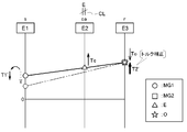
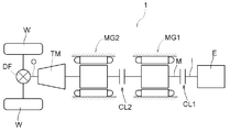
- the vehicle drive device 1 is a drive device for driving a vehicle (hybrid vehicle) including an internal combustion engine E and rotating electrical machines MG1 and MG2 as a driving force source for wheels W. (Hybrid vehicle drive device).
- the vehicle drive device 1 which concerns on this embodiment is provided with the control apparatus 70 (refer FIG. 3), and this control apparatus 70 controls operation
- a broken line indicates a power transmission path
- a solid arrow indicates a transmission path for various information.
- the differential gear device DG provided in the vehicle drive device 1 is constituted by a planetary gear mechanism having a sun gear s, a carrier ca, and a ring gear r as rotating elements.
- the first rotating electrical machine MG1 is drivingly connected to the sun gear s
- the second connecting member 42 is drivingly connected to the carrier ca
- the second rotating electrical machine MG2 is connected to the ring gear r without passing through other rotating elements of the planetary gear mechanism.
- the output member O is drivingly connected.
- the second connecting member 42 is drivingly connected to the internal combustion engine E via the damper device DA and the input member I
- the output member O is drivingly connected to the wheels W.
- the second connecting member 42 and the damper device DA are drivingly connected so as to rotate integrally
- the “intermediate member M” is configured by the second connecting member 42 and the damper device DA.
- the vehicle drive device 1 includes a friction engagement device CL that can release the drive connection between the intermediate member M and the input member I. Further, the vehicle drive device 1 is configured such that the vehicle travels with the torque of the second rotating electrical machine MG2 while the internal combustion engine E is stopped, and the torque of the internal combustion engine E is applied to the first rotating electrical machine MG1 and the output member O. It has a hybrid travel mode (in this example, a split travel mode) in which the vehicle is distributed and travels. When switching from the electric travel mode to the hybrid travel mode, the friction engagement device CL is synchronously engaged from the released state, and the internal combustion engine E is driven by the torque of the first rotating electrical machine MG1 in the direct engagement state of the friction engagement device CL. Control for starting is executed.
- a hybrid travel mode in this example, a split travel mode
- the vehicle drive device 1 according to the present embodiment is input to the intermediate member M, which is a rotating member on both sides of the friction engagement device CL, which is synchronously engaged with the rotation speed being zero. It is characterized in that predetermined alignment control can be executed in order to prevent the eccentric state from being continued when the member I is in an eccentric state.
- predetermined alignment control can be executed in order to prevent the eccentric state from being continued when the member I is in an eccentric state.
- the vehicle drive device 1 includes an input member I drivingly connected to the internal combustion engine E, an output member O drivingly connected to the wheels W, a first rotating electrical machine MG1, a second rotating electrical machine MG2, and an input member I.
- An intermediate member M that is in a power transmission path connecting the output member O and is drivingly connected to the first rotating electrical machine MG1, a differential gear device DG having at least three rotating elements, and a control device 70. Yes.
- the vehicle drive device 1 according to the present embodiment distributes the torque of the internal combustion engine E to the first rotating electrical machine MG1 side and the wheels W and the second rotating electrical machine MG2 side. It is configured as a drive device for a so-called two-motor split type hybrid vehicle equipped with DG.
- the vehicle drive device 1 shown in FIG. 1 is suitable as a configuration when mounted on, for example, an FF (Front Engine Front Drive) vehicle.
- the differential gear device DG is constituted by a single pinion type planetary gear mechanism. That is, the differential gear device DG has three rotating elements, specifically, a sun gear s, a carrier ca, and a ring gear r in this example. Then, as described below, the intermediate member M, the output member O, and the first rotating electrical machine MG1 are respectively connected to different rotating elements of the differential gear device DG via other rotating elements of the differential gear device DG. It is connected without driving. In this example, the first rotating electrical machine MG1 is drivingly connected to the sun gear s, the intermediate member M is drivingly connected to the carrier ca, and the output member O is drivingly connected to the ring gear r.
- the rotational speeds of the three rotating elements of the differential gear device DG are in the order of the sun gear s, the carrier ca, and the ring gear r (see FIG. 4 and the like). Assuming that these three rotating elements of the differential gear device DG are “first rotating element E1”, “second rotating element E2”, and “third rotating element E3” in the order of rotation speed, in this embodiment, the sun gear s Is the first rotating element E1, the carrier ca is the second rotating element E2, and the ring gear r is the third rotating element E3.
- the second rotating electrical machine MG2 is a rotating element of the differential gear device DG other than the first rotating element E1 (sun gear s) and the second rotating element E2 (carrier ca) (in this example, the ring gear r that is the third rotating element E3). ) To the differential gear device DG without being driven through another rotating element. Further, the vehicle drive device 1 includes a second rotating element E2 (carrier ca) and a friction engagement device CL capable of releasing the drive connection between the intermediate member M and the input member I.
- a connecting member that rotates integrally with the rotating element is connected to each rotating element of the differential gear device DG.
- a first connecting member 41 is connected to the sun gear s
- a second connecting member 42 constituting an intermediate member M is connected to the carrier ca
- a third gear is connected to the ring gear r.
- the connecting member 43 is connected.
- the first rotating electrical machine MG1 is drivingly connected to the sun gear s by being drivingly connected to the first connecting member 41.
- the first rotating electrical machine MG1 is drivingly connected to the second connecting member 42 constituting the intermediate member M via the sun gear s and the carrier ca.
- the first rotating electrical machine MG1 is drivably coupled to the second coupling member 42 constituting the intermediate member M without the friction engagement device CL.
- the input member I is drivably coupled to the carrier ca by being drivably coupled to the second coupling member 42 via the friction engagement device CL and the damper device DA.
- the input member I is drivingly connected to the internal combustion engine E without going through the friction engagement device CL.
- the output member O and the second rotating electrical machine MG2 are drivably coupled to the ring gear r by being drivably coupled to the third coupling member 43 via the counter gear mechanism C and the counter drive gear 52.
- the input member I is drivingly connected to the internal combustion engine E.
- the input member I is a shaft member (input shaft).
- the internal combustion engine E is a prime mover that outputs power by combustion of fuel.
- a spark ignition engine such as a gasoline engine or a compression ignition engine such as a diesel engine can be used.
- the input member I is drivingly connected so as to rotate integrally with an output shaft of an internal combustion engine such as a crankshaft of the internal combustion engine E. Therefore, the rotational speed of the input member I becomes equal to the rotational speed of the internal combustion engine E.
- the input member I and the internal combustion engine E are drivably coupled to the intermediate member M via a power input unit mainly composed of the friction engagement device CL and the damper device DA. The configuration of the power input unit will be described later.
- the output member O is drivingly connected to the wheel W.
- the output member O is a gear member, and specifically, a differential input gear provided in the output differential gear device D.
- the output differential gear device D is configured by a differential gear mechanism using a plurality of bevel gears that mesh with each other, and the torque transmitted to the output member O is applied to the left and right wheels W that serve as drive wheels. Distribute.
- a first rotating electrical machine MG1 as a rotating electrical machine includes a first stator St1 fixed to a case (driving device case) CS and a first rotor Ro1 that is rotatably supported on the radially inner side of the first stator St1.
- the first rotor Ro1 is drivingly connected to rotate integrally with the first rotating element E1 (sun gear s in this example) via a first connecting member 41 as a first rotor shaft to which the first rotor Ro1 is fixed.
- the second rotating electrical machine MG2 includes a second stator St2 fixed to the case CS, and a second rotor Ro2 that is rotatably supported on the radially inner side of the second stator St2.
- the second rotor Ro2 is drivingly connected to rotate integrally with the second rotating electrical machine output gear 55 via a second rotor shaft to which the second rotor Ro2 is fixed.
- the first rotating electrical machine MG1 is electrically connected to the power storage device B via the first inverter 4, and the second rotating electrical machine MG2 is connected to the power storage device B via the second inverter 5. Is electrically connected.
- the power storage device B a battery, a capacitor, or the like can be used.
- each of the first rotating electrical machine MG1 and the second rotating electrical machine MG2 has a function as a motor (electric motor) that receives power supplied from the power storage device B and generates power (torque), It is possible to function as a generator (generator) that receives the supply to generate electric power and supplies the generated electric power to the power storage device B.
- the counter gear mechanism C includes a first counter gear 53, a second counter gear 54, and a counter shaft that is coupled so as to rotate integrally.
- the third connecting member 43 has a counter drive gear 52 that meshes with the first counter gear 53.
- the second rotating electrical machine output gear 55 is arranged so as to mesh with the first counter gear 53 at a position different from the counter drive gear 52 in the circumferential direction (the circumferential direction of the first counter gear 53).
- the electric machine MG2 is drivingly connected to the third rotating element E3.
- the output member O is disposed so as to mesh with the second counter gear 54, and is drivingly connected to the third rotating element E3.
- the rotational speed relationships among the third rotating element E3, the second rotating electrical machine MG2, and the output member O are proportional to each other, and the proportionality coefficient (that is, the rotational speed ratio) is It becomes a value corresponding to the number of teeth of the gear interposed therebetween.
- the vehicle drive device 1 includes a hybrid travel mode (split travel mode) in which the vehicle travels with the torque of both the internal combustion engine E and the rotating electrical machines MG1 and MG2, and the rotating electrical machine MG1. , MG2 (in this example, only the second rotating electrical machine MG2) and an electric travel mode in which the vehicle is traveled only by the torque.
- hybrid travel mode split travel mode
- MG2 in this example, only the second rotating electrical machine MG2
- an electric travel mode in which the vehicle is traveled only by the torque.
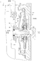
- the power input unit is a mechanism unit for transmitting the torque of the internal combustion engine E transmitted to the input member I to the intermediate member M.
- the power input unit may transmit the torque of the first rotating electrical machine MG1 transmitted to the intermediate member M to the input member I.
- a power input unit is mainly configured by the friction engagement device CL and the damper device DA.
- the power input unit also includes a flywheel 21.
- a flywheel 21 formed in a disk shape is connected to the input member I so as to rotate integrally with the input member I.
- a clutch cover 22 is fixed to the differential gear device DG side (left side in FIG. 2) in the axial direction at the radially outer end of the flywheel 21.
- a pressure plate 23 as a pressing member formed in an annular shape is disposed.
- a radially outer end of a diaphragm spring 25 that is an elastic member is in contact with the pressure plate 23 from the side opposite to the flywheel 21 (the differential gear device DG side).
- the diaphragm spring 25 is supported by a pair of pivot rings 24 held by the clutch cover 22, and presses the pressure plate 23 toward the flywheel 21 (the right side in FIG. 2) by the elastic force of the diaphragm spring 25. Is possible.
- the frictional engagement device CL is provided so as to be able to switch between transmission and interruption of driving force between the flywheel 21 and the damper device DA, thereby selectively drivingly connecting the input member I and the intermediate member M. Is provided.
- the friction engagement device CL according to the present embodiment is configured as a dry single-plate clutch mechanism having a clutch release mechanism including a release fork 32, a diaphragm spring 25, and the like.
- the one end portion of the release fork 32 that is a fork member is divided into two parts so as to sandwich the second connecting member 42.
- the release fork 32 is disposed along the radial direction of the second connecting member 42 and is fixed to the case CS so as to be swingable about a predetermined pivot shaft 33 as a fulcrum.
- a drive motor 31 as a driving force source of the clutch release mechanism of the friction engagement device CL is drivably coupled to a predetermined portion of the release fork 32 opposite to the second coupling member 42 with respect to the pivot shaft 33. ing.
- the drive motor 31 is drivingly connected to the release fork 32 via a mechanism (for example, a mechanism including a ball screw and a nut) that converts the rotational motion into a linear motion.
- Drive motor 31 is driven using the electric power of power storage device B.
- a cylindrical boss Cb formed in the case CS so as to surround the second connecting member 42 is extrapolated in a state where a release bearing 35 as a clutch bearing is held by the cage 34.
- the inner ring of the release bearing 35 is disposed so as to be able to abut on the radially inner end of the diaphragm spring 25.
- the retainer 34 and the release bearing 35 are disposed closer to the flywheel 21 than the release fork 32 and are pushed by the release fork 32 that swings about the pivot shaft 33 as the drive motor 31 is driven. , And can move to the flywheel 21 side along the boss Cb.
- a clutch disk 27 is disposed as a friction member integrally connected to the damper device DA on the radially outer side of the damper device DA.
- the clutch disk 27 has a friction contact portion that contacts each of the pressure plate 23 and the flywheel 21, and the flywheel 21 is sandwiched between the pressure plate 23 and the flywheel 21 with a predetermined engagement pressure.
- the driving force is transmitted to the 21.
- the engagement pressure between the pressure plate 23 and the flywheel 21 can be controlled according to the amount of displacement of the release fork 32 accompanying the drive of the drive motor 31.
- the state indicated by the solid line in FIG. 2 is the “minimum displacement state” in which the displacement amount of the release fork 32 is the minimum (zero), and the state indicated by the two-dot chain line in FIG.
- the maximum amount is the “maximum displacement state”.
- the driving force in the minimum displacement state of the release fork 32, the driving force can be transmitted while the pressure plate 23, the flywheel 21, the clutch disk 27, and the damper device DA rotate integrally by the elastic force of the diaphragm spring 25. It becomes a state. In the present embodiment, this state is referred to as “directly engaged state” of the friction engagement device CL.
- the pressure plate 23, the flywheel 21, the clutch disc 27, and the damper device DA are in a state where the rotation and driving force are not transmitted. In the present embodiment, this state is referred to as a “released state” of the friction engagement device CL.
- this state is referred to as a “slip engagement state” of the friction engagement device CL.
- the damper device DA transmits the rotation of the output shaft of the internal combustion engine to the second connecting member 42 while attenuating the torsional vibration of the output shaft of the internal combustion engine transmitted to the input member I in the direct engagement state of the friction engagement device CL.
- the damper device DA has a cylindrical portion 28 at its radially inner end, and a spline groove is formed on the inner peripheral surface of the cylindrical portion 28.
- the spline groove of the cylindrical portion 28 is engaged with spline teeth formed on the outer peripheral surface of the second connecting member 42. That is, the damper device DA and the second connecting member 42 are drivingly connected so as to rotate integrally through the spline connecting portion 29.
- a predetermined clearance exists between the inner peripheral surface of the cylindrical portion 28 and the outer peripheral surface of the second connecting member 42.
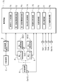
- the control device 70 includes a travel mode determination unit 71, a first rotating electrical machine control unit 72, a second rotating electrical machine control unit 73, an engagement state control unit 74, and synchronous engagement control. Unit 75, start control unit 76, and alignment control unit 77.
- the control device 70 includes an arithmetic processing device such as a CPU as a core, and includes a storage device such as a RAM and a ROM. Each functional unit of the control device 70 is configured by software (program) stored in a ROM or the like, hardware such as a separately provided arithmetic circuit, or both. Each of these functional units is configured to exchange information with each other.
- the control device 70 is configured to be able to acquire information from a sensor or the like provided in each part of the vehicle in order to acquire information of each part of the vehicle on which the vehicle drive device 1 is mounted.
- the control device 70 includes an input member sensor Se1, a second connecting member sensor Se2, a first connecting member sensor Se3, an output member sensor Se4, a power storage state sensor Se10, and an accelerator opening. Information from the sensor Se11 can be acquired.
- the input member sensor Se1 is a sensor that detects the rotational speed of the input member I.
- the second connecting member sensor Se ⁇ b> 2 is a sensor that detects the rotational speed of the second connecting member 42.
- the rotational speed of the second connecting member 42 detected by the second connecting member sensor Se2 is equal to the rotational speed of the second rotating element E2 (carrier ca) of the differential gear device DG.
- the first connecting member sensor Se ⁇ b> 3 is a sensor that detects the rotational speed of the first connecting member 41.
- the rotational speed of the first connecting member 41 detected by the first connecting member sensor Se3 is equal to the rotational speed of the first rotating element E1 (sun gear s) of the first rotating electrical machine MG1 and the differential gear device DG.
- the first connecting member sensor Se3 can be, for example, a rotation sensor (such as a resolver) provided in the first rotating electrical machine MG1.
- the output member sensor Se4 is a sensor that detects the rotation speed of the output member O.
- the control device 70 can derive the vehicle speed based on the rotation speed of the output member O detected by the output member sensor Se4.
- the output member sensor Se4 may be any sensor that can detect the rotational speed of any member that rotates at a rotational speed proportional to the rotational speed of the output member O. Therefore, for example, it is preferable to use a rotation sensor (such as a resolver) provided in the second rotating electrical machine MG2.
- the accelerator opening sensor Se11 is a sensor that detects the accelerator opening by detecting an operation amount of an accelerator pedal (not shown).
- the power storage state sensor Se10 is a sensor that detects the state of the power storage device B (such as the amount of power storage). In the present embodiment, the power storage state sensor Se10 includes a voltage sensor, a current sensor, and the like, and detects the amount of power stored by detecting SOC (state of charge).
- the vehicle is provided with an internal combustion engine control unit 3.
- the internal combustion engine control unit 3 controls the operation of the internal combustion engine E by controlling each part of the internal combustion engine E.
- the internal combustion engine control unit 3 sets a target torque and a target rotational speed as control targets for the torque and rotational speed of the internal combustion engine E, and operates the internal combustion engine E according to the control target, thereby operating the internal combustion engine E.
- the target torque and the target rotation speed are set based on a command from the control device 70.
- the internal combustion engine control unit 3 changes the internal combustion engine E in the stopped state (combustion stopped state) to the start state and changes the internal combustion engine E in the start state to the stopped state in accordance with a command from the control device 70.
- the travel mode determination unit 71 is a functional unit that determines the travel mode of the vehicle.
- the traveling mode determination unit 71 includes a vehicle speed derived based on the detection result of the output member sensor Se4, an accelerator opening detected by the accelerator opening sensor Se11, and a storage state detected by the storage state sensor Se10.
- the driving mode to be realized by the vehicle drive device 1 is determined based on the above.
- the travel modes that can be determined by the travel mode determination unit 71 include a hybrid travel mode and an electric travel mode.
- the travel mode determination unit 71 refers to a mode selection map (not shown) that preliminarily stores and defines the relationship between the vehicle speed, the accelerator opening, and the storage state (storage amount) and the travel mode. To determine the driving mode.
- the hybrid travel mode is a travel mode in which the vehicle travels with the torque of both the internal combustion engine E and the rotating electrical machines MG1, MG2.
- the hybrid travel mode according to the present embodiment is a split travel mode, in which the friction engagement device CL is in a direct engagement state, and the torque of the internal combustion engine E transmitted via the input member I and the intermediate member M is differential.
- the gear device DG is transmitted to the output member O while being distributed to the first rotary electric machine MG1.
- the internal combustion engine E is controlled in such a way as to be maintained in a state with high efficiency and low exhaust gas (a state in accordance with optimum fuel consumption characteristics), and a positive torque corresponding to a required driving force for traveling the vehicle.
- the first rotating electrical machine MG1 outputs a torque in the negative direction and transmits it to the first rotating element E1, and functions as a reaction force receiver for the torque of the internal combustion engine E.
- the torque attenuated with respect to the torque of the internal combustion engine E is transmitted to the output member O that is drivingly connected to the third rotating element E3. As a result, the vehicle is caused to travel.
- the first rotating electrical machine MG1 basically generates power by rotating in the positive direction while outputting a torque in the negative direction.
- the second rotating electrical machine MG2 assists the torque transmitted to the output member O by outputting a positive torque as necessary.
- the first rotating electrical machine MG1 may rotate negatively while outputting torque in the negative direction, and the second rotating electrical machine MG2 may generate electric power for driving the first rotating electrical machine MG1. is there.
- the vehicle can travel while generating power using the large torque of the internal combustion engine E while driving the internal combustion engine E efficiently.
- the electric travel mode is a travel mode that travels only by the torque of the second rotating electrical machine MG2.
- the friction engagement device CL is released, and only the torque of the second rotating electrical machine MG2 is transmitted to the output member O when the internal combustion engine E is stopped.
- torque is not transmitted via the first rotating element E1 and the second rotating element E2, and only the torque of the second rotating electrical machine MG2 that is drivingly connected to the third rotating element E3 is also the third. It is transmitted to the output member O that is drivingly connected to the rotating element E3.
- Second rotating electrical machine MG2 outputs a torque corresponding to the required driving force to drive the vehicle.
- the rotational speed of the first rotating electrical machine MG1 is substantially zero, and the internal combustion engine E is disconnected from the wheels W in the released state of the friction engagement device CL, so that the first rotating electrical machine MG1 is idling. It is possible to improve energy efficiency by avoiding (dragging).
- the transition to the hybrid traveling mode is determined.
- the internal combustion engine start condition is a condition for starting the internal combustion engine E in a stopped state, and is satisfied when the vehicle is in a situation that requires the torque of the internal combustion engine E.
- the driver strongly depresses the accelerator pedal.
- the internal combustion engine start condition is satisfied.
- the internal combustion engine start condition is satisfied.
- the synchronous engagement control unit 75 and the start control unit 76 cooperate to start the internal combustion engine E with the torque of the first rotating electrical machine MG1. This point will be described later.
- the shift to the electric travel mode is determined.
- the internal combustion engine stop condition is satisfied when the vehicle does not need the torque of the internal combustion engine E.
- the friction engagement device CL is released, and then the internal combustion engine E and the first rotating electrical machine MG1 are stopped (the internal combustion engine E and the first engine).
- the rotational speed of the single-rotary electric machine MG1 is zero).
- the first rotating electrical machine control unit 72 as the rotating electrical machine control unit is a functional unit that performs operation control of the first rotating electrical machine MG1. Specifically, the first rotating electrical machine control unit 72 commands a target torque and a target rotational speed as control targets for the torque and rotational speed of the first rotating electrical machine MG1, and the first rotating electrical machine MG1 according to the control target.
- the first inverter 4 is controlled so as to operate.
- the first rotating electrical machine control unit 72 performs operation control of the first rotating electrical machine MG1 by torque control or rotational speed control.
- the torque control is a control for instructing a target torque for the first rotating electrical machine MG1 so that the torque of the first rotating electrical machine MG1 matches the target torque.
- the rotational speed control is a control for instructing a target rotational speed for the first rotating electrical machine MG1 so that the rotational speed of the first rotating electrical machine MG1 coincides with the target rotational speed.
- the second rotating electric machine control unit 73 is a functional unit that controls the operation of the second rotating electric machine MG2. Specifically, the second rotating electrical machine control unit 73 commands a target torque and a target rotational speed as control targets for the torque and rotational speed of the second rotating electrical machine MG2, and the second rotating electrical machine MG2 according to the control target.
- the second inverter 5 is controlled so as to operate.
- the second rotating electrical machine control unit 73 controls the operation of the second rotating electrical machine MG2 by torque control or rotational speed control.
- the torque control is a control in which a target torque for the second rotating electrical machine MG2 is commanded so that the torque of the second rotating electrical machine MG2 matches the target torque.
- the rotational speed control is a control for instructing a target rotational speed for the second rotating electrical machine MG2 so that the rotational speed of the second rotating electrical machine MG2 matches the target rotational speed.
- the second rotating electrical machine control unit 73 controls the second rotating electrical machine MG2 so that the torque transmitted to the output member O becomes a torque corresponding to the required driving force for driving the vehicle.
- the second rotating electrical machine control unit 73 controls the torque of the second rotating electrical machine MG ⁇ b> 2 so that a torque that compensates for a shortage of the torque of the internal combustion engine E is transmitted to the output member O.
- the second rotating electrical machine control unit 73 controls the torque of the second rotating electrical machine MG2 so that the torque that matches the required driving force is transmitted to the output member O.
- the engagement state control unit 74 is a functional unit that controls the state of the friction engagement device CL.
- the engagement state control unit 74 controls the operation of the drive motor 31 provided as a driving force source of the clutch release mechanism of the friction engagement device CL, thereby changing the state of the friction engagement device CL. Control.
- the engagement state control unit 74 controls the engagement pressure of the friction engagement device CL by controlling the rotational speed and drive time of the drive motor 31 to control the displacement amount of the release fork 32.
- the friction engagement device CL is controlled to any one of the released state, the direct connection engagement state, and the slip engagement state.
- the engagement state control unit 74 controls the state of the friction engagement device CL according to the travel mode determined by the travel mode determination unit 71. For example, the engagement state control unit 74 sets the friction engagement device CL to the direct engagement state when the hybrid travel mode is selected, and sets the friction engagement device CL to the release state when the electric travel mode is selected. In addition, the engagement state control unit 74 is frictionally engaged in accordance with a command from the alignment control unit 77 so that the slip engagement state is temporarily set in the transition process between the hybrid travel mode and the electric travel mode as described later. Control device CL.
- the synchronous engagement control unit 75 is a functional unit that executes synchronous engagement control in which the friction engagement device CL is engaged (synchronously engaged) in a synchronized state to be in a directly connected state. .
- the synchronous engagement control unit 75 executes this synchronous engagement control when the internal combustion engine start condition is satisfied in the released state of the friction engagement device CL.
- the traveling mode determining unit 71 determines to switch the traveling mode from the electric traveling mode to the hybrid traveling mode
- the synchronous engagement control unit 75 acquires a differential rotational speed ⁇ N between the input member I and the intermediate member M, which are rotary members on both sides of the friction engagement device CL.
- the differential rotation speed ⁇ N is obtained by subtracting the rotation speed of the input member I detected by the input member sensor Se1 from the rotation speed of the second connection member 42 (intermediate member M) detected by the second connection member sensor Se2. It can be calculated and obtained as the subtracted value.
- the internal combustion engine E is stopped during traveling in the electric traveling mode, and its rotational speed is zero.
- the synchronous engagement control unit 75 is in the state where the second connection member 42 (intermediate member) detected by the second connection member sensor Se2 is in a state where the vehicle is traveling in the electric travel mode and before the internal combustion engine E starts to rotate.
- the rotational speed of M) can be obtained as it is as the differential rotational speed ⁇ N.
- the synchronous engagement control unit 75 instructs the first rotating electrical machine control unit 72 to change the rotational speed of the first rotating electrical machine MG1 so as to reduce the differential rotational speed ⁇ N.
- the synchronous engagement control unit 75 sets the differential rotation speed ⁇ N to be equal to or less than the synchronization determination threshold value ⁇ Ns1 based on the acquired differential rotation speed ⁇ N and a preset synchronization determination threshold value ⁇ Ns1 (see FIG. 8). In this case, it is determined that the state is “synchronized state”.
- the synchronous engagement control unit 75 controls the operation of the drive motor 31 by instructing the engagement state control unit 74 on the condition that the input member I and the intermediate member M are in a synchronized state, and the friction engagement device CL. Is switched from the released state to the directly connected state.
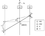
- each speed diagram referred to in the following description corresponds to the rotational speed of each rotating element. That is, “0” appended to the vertical axis indicates that the rotation speed is zero, and the upper side is positive rotation (rotation speed is positive) and the lower side is negative rotation (rotation speed is negative). Further, each of the plurality of vertical lines arranged in parallel corresponds to each rotation element of the differential gear device DG. Further, on the speed diagram, the rotational speed of the first rotating electrical machine MG1, the rotational speed of the second rotating electrical machine MG2, the rotational speed of the internal combustion engine E (input member I), and the rotational speed of the output member O are mutually different. Shown with different symbols. In addition, in order to make an understanding of invention easy, regarding the rotational speed of the 2nd rotary electric machine MG2 and the output member O, the rotational speed transmitted to the 3rd rotation element E3 is shown.
- T1 indicates the torque of the first rotating electrical machine MG1 transmitted to the first rotating element E1 (sun gear s), and “T2” indicates the second rotating electrical machine transmitted to the third rotating element E3 (ring gear r).
- the torque of MG2 is shown.
- Te indicates the torque of the internal combustion engine E transmitted to the second rotating element E2 (carrier ca) via the friction engagement device CL in the directly coupled state, and “To” indicates from the output member O (wheel W).
- the running torque (running resistance) transmitted to the third rotating element E3 is shown. In the arrows arranged adjacent to these torques, an upward arrow indicates a positive torque, and a downward arrow indicates a negative torque.
- the operating state of the differential gear device DG in the electric travel mode is indicated by a two-dot chain line.
- the friction engagement device CL is released, and the internal combustion engine E is disconnected from the second rotating element E2 of the differential gear device DG.
- the 2nd rotation element E2 will be in the state which can rotate freely.
- the rotation speed of the first rotating electrical machine MG1 is set to zero
- the second rotating element E2 is set to the rotational speed of the third rotating element E3 determined according to the vehicle speed and the rotating speed of the first rotating electrical machine MG1 (here, zero). )
- the synchronous engagement control unit 75 reduces the rotation speed of the second rotation element E2 connected so as to decrease the differential rotation speed ⁇ N, that is, to rotate integrally with the intermediate member M.
- the single-rotary electric machine MG1 is caused to output a torque in the negative direction to reduce the rotational speed from zero.
- the third rotating element E3 determined according to the vehicle speed is maintained at a substantially constant rotational speed.
- the rotation speed of the second rotation element E2 gradually decreases with the rotation element E3 as a fulcrum.
- the synchronous engagement control unit 75 is in a synchronized state. judge.
- a preset synchronization determination threshold value ⁇ Ns1 for example, a value of 0 to 50 [rpm] can be set, and in this example, it is set to 0 [rpm].
- the synchronous engagement control unit 75 detects that the rotation speeds of the second rotation element E2 and the intermediate member M have decreased to zero before long, the synchronous engagement control unit 75 determines that the synchronization is in the synchronized state, The friction engagement device CL is brought into a direct engagement state via the control unit 74.
- the operating state of the differential gear device DG in this synchronized state is indicated by a solid line.
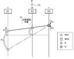
- the start control unit 76 is a functional unit that executes internal combustion engine start control for starting the internal combustion engine E by increasing the rotation speed of the input member I by the torque of the first rotating electrical machine MG1.
- the start control unit 76 performs the internal combustion engine start control with the friction engagement device CL in the directly connected state. That is, after the friction engagement device CL is brought into the direct engagement state by the synchronous engagement control unit 75 executing the synchronous engagement control, the direct engagement state of the friction engagement device CL is maintained, The start control unit 76 executes internal combustion engine start control.
- the rotational speed of the first rotating electrical machine MG1 is changed so as to have a rotational speed at which the internal combustion engine E can be started.
- the start control unit 76 instructs the first rotating electrical machine control unit 72 to change the rotation speed of the first rotating electrical machine MG1 in the direction opposite to the direction of change in the synchronous engagement control.
- the first rotating electrical machine MG1 outputs negative torque to reduce the rotational speed (see FIG. 4), whereas the internal combustion engine start control by the start control unit 76 is performed. Then, the first rotating electrical machine MG1 outputs a torque in the positive direction to increase the rotational speed (see FIG. 5).
- the operating state of the differential gear device DG in the synchronized state is indicated by a two-dot chain line. If the rotational speed of the first rotating electrical machine MG1 is increased by the internal combustion engine start control from this state, the rotational speed of the first rotating element E1 also increases as the rotational speed of the first rotating electrical machine MG1 increases. Then, the rotation speed of the second rotation element E2 gradually increases with the third rotation element E3 as a fulcrum while the rotation speed of the third rotation element E3 determined according to the vehicle speed is maintained substantially constant.
- the rotation speed control of the first rotating electrical machine MG1 is executed in the internal combustion engine start control. That is, in the internal combustion engine start control, the first rotating electrical machine control unit 72 commands the target rotational speed for the first rotating electrical machine MG1, and executes control to make the rotational speed of the first rotating electrical machine MG1 coincide with the target rotational speed. .
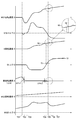
- the target rotational speed of the first rotating electrical machine MG1 is set to the rotational speed of the first rotating electrical machine MG1 that makes the rotational speed of the internal combustion engine E startable (ignition rotational speed Nf; see FIG. 8).
- the first rotating electrical machine MG1 outputs a large positive torque. Thereafter, as the rotational speed of the internal combustion engine E increases, such load torque decreases over time, and the torque of the first rotating electrical machine MG1 for maintaining the target rotational speed gradually decreases (see FIG. 8).
- the start control unit 76 determines that the internal combustion engine E can be ignited, and instructs the internal combustion engine control unit 3 to The internal combustion engine E is started.
- the ignition rotational speed Nf is a rotational speed at which the internal combustion engine E can be ignited and started (for example, a rotational speed during idling), and in this example, is higher than an alignable rotational speed NI described later. A large value is set (see FIG. 8).
- the internal combustion engine E when the internal combustion engine E is started by the internal combustion engine start control and starts a self-sustaining operation, the internal combustion engine E starts to output a positive torque. Then, the positive torque of the internal combustion engine E is transmitted to the first rotating electrical machine MG1 via the friction engagement device CL and the differential gear device DG, and the rotational speed of the first rotating electrical machine MG1 tends to increase.
- the rotation speed control of the first rotating electrical machine MG1 is executed in the internal combustion engine start control, and in this embodiment, the rotation speed control is continuously executed even after the internal combustion engine E is started. Therefore, the first rotating electrical machine control unit 72 outputs the torque in the direction opposite to that at the start of the internal combustion engine E so that the rotational speed of the first rotating electrical machine MG1 matches the target rotational speed. Control MG1.
- the first rotating electrical machine control unit 72 outputs the torque in the positive direction to the first rotating electrical machine MG1 to increase the rotational speed before the internal combustion engine E is started, whereas the internal combustion engine E After starting, the first rotating electrical machine MG1 is caused to output a torque in the negative direction so that its rotational speed matches the target rotational speed.
- the direction of the torque of the first rotating electrical machine MG1 is reversed from the positive direction to the negative direction before and after the internal combustion engine E is started and starts the self-sustaining operation. Thereby, it is possible to smoothly shift to the hybrid travel mode with the execution of the internal combustion engine start control and the rotational speed control of the first rotating electrical machine MG1 that are performed simultaneously.
- the mode switching from the electric travel mode to the hybrid travel mode is performed by the synchronous engagement control unit 75 through the stopped state of the internal combustion engine E and the synchronized state of the input member I and the intermediate member M.
- Both the input member I and the intermediate member M have an aspect in which the rotational speed is zero. Therefore, the input member I and the intermediate member M can be in an eccentric state. That is, in this embodiment, the intermediate member M is constituted by the second connecting member 42 and the damper device DA, and these are driven and connected to rotate integrally through the spline connecting portion 29 as shown in FIG. Yes.
- a predetermined clearance exists between the inner peripheral surface of the cylindrical portion 28 of the damper device DA and the outer peripheral surface of the second connecting member 42 in the spline connecting portion 29. Therefore, when the rotational speed of the intermediate member M is zero, at least the shaft center adjustment function due to the rotation of the damper device DA itself does not work, and the damper device DA moves vertically downward by its own weight and the clearance is uneven. It becomes a state. In other words, the clearance vertically below the second connecting member 42 is larger than the clearance vertically above the second connecting member 42.
- the input member I is always maintained in good axial accuracy through an input bearing (not shown), and the second connecting member 42 constituting the intermediate member M is also an intermediate bearing (see FIG.
- the axial center accuracy is always maintained well through (not shown). Therefore, when the rotational speed of the intermediate member M is zero and only the damper device DA is moving vertically downward, the input member I and the intermediate member M are in an eccentric state as a whole.
- the frictional engagement device CL is brought into the direct engagement state in this state, the radial position is constrained by the frictional engagement device CL while the input member I and the intermediate member M are eccentric from each other. become.
- the control device 70 When the vehicle continues to run while the eccentric state is maintained, the input member I and the intermediate member M which are in an eccentric state sway and vibrate as a whole. There is a possibility that the load acting on the intermediate bearing that supports the two connecting members 42 becomes large. Therefore, in order to suppress such an eccentric state from being maintained, the control device 70 according to the present embodiment includes an alignment control unit 77.
- the alignment control unit 77 adjusts the friction engagement device CL as a slip engagement state temporarily while the internal combustion engine E is rotating at a rotation speed equal to or higher than a predetermined rotation speed. It is a functional unit that performs heart movement (alignment control).
- an alignment operation when the engagement pressure of the friction engagement device CL is decreased and it is detected that the differential rotational speed ⁇ N between the input member I and the intermediate member M is equal to or greater than the slip determination threshold ⁇ Ns2, friction is detected.
- the operation for returning the engagement device CL to the direct engagement state is referred to as “alignment operation”.
- the “internal combustion engine rotation state” is a state in which the rotation speed of the internal combustion engine E is equal to or higher than the alignable rotation speed NI set to a value smaller than the ignition rotation speed Nf in the present embodiment. That is, the alignment control unit 77 performs alignment operation in a state where at least the rotation speed of the internal combustion engine E is equal to or higher than the rotation speed NI that can be aligned.
- the alignable rotation speed NI is set in advance to a rotation speed that is equal to or higher than a rotation speed (for example, 200 [rpm]) at which the internal combustion engine E and the input member I can exhibit the shaft center adjustment function.
- the alignable rotation speed NI is set to a value slightly smaller than the ignition rotation speed Nf (see FIG. 8).
- the alignment control unit 77 further performs alignment operation after the torque of the internal combustion engine E becomes equal to or higher than a predetermined start determination torque TI.
- a start determination torque TI is set in advance as a torque when the internal combustion engine E starts a self-sustained operation and the internal combustion engine E starts outputting torque.
- the rotational speed of the internal combustion engine E is equal to or higher than the ignition rotational speed Nf, and the rotational speed of the internal combustion engine E is higher than the alignable rotational speed NI.
- the alignment operation can be reliably performed in the rotation state of the internal combustion engine. Moreover, when performing the alignment operation, there is also an advantage that the shaft center adjustment function can be operated by utilizing the rotation and torque of the internal combustion engine E that has started the independent operation.
- the alignment control unit 77 further detects a torque reversal in which the direction of the torque of the first rotating electrical machine MG1 is reversed while the rotational speed control of the first rotating electrical machine MG1 is being performed. Then, after detecting the torque reversal, the alignment operation is performed.
- the alignment control unit 77 can detect torque reversal by monitoring the command value of the target torque for the first rotating electrical machine MG1 output from the first rotating electrical machine control unit 72.
- the alignment control unit 77 starts the alignment operation when detecting the torque reversal in which the direction of the torque of the first rotating electrical machine MG1 is reversed. That is, the alignment control unit 77 detects torque reversal, and at the same time, instructs the engagement state control unit 74 to control the operation of the drive motor 31 to apply the engagement pressure of the friction engagement device CL (the clutch disk 27 The engagement pressure between the pressure plate 23 and the flywheel 21 to be sandwiched is reduced.
- the engagement pressure of the friction engagement device CL is relatively large, the restraining force due to the engagement pressure is large, and the restraining force is superior to the swinging torque due to the eccentricity between the input member I and the intermediate member M. Therefore, the friction engagement device CL is maintained in the direct engagement state, and the radial positions of the input member I and the intermediate member M are maintained as they are due to the engagement pressure of the friction engagement device CL.
- the flywheel 21 and the pressure plate 23 A slip occurs with the clutch disk 27. That is, the friction engagement device CL is in the slip engagement state.
- the internal combustion engine is already rotating when this slip occurs, and in this embodiment, the input member I and the intermediate member M are rotating at a rotational speed sufficiently higher than the alignable rotational speed NI. Therefore, while the friction engagement device CL is in the slip engagement state, that is, while the restraining force due to the engagement pressure of the friction engagement device CL is loosened, the rotation of the input member I and the intermediate member M respectively.
- the shaft center adjustment function can be activated.
- the shaft center adjusting function by the rotation of the damper device DA constituting the intermediate member M can be operated. That is, the clearance between the inner peripheral surface of the cylindrical portion 28 of the damper device DA and the outer peripheral surface of the second connecting member 42 can be equalized and aligned over the entire periphery. Thereby, it is possible to prevent the eccentric state between the input member I and the intermediate member M, which are rotating members on both sides of the friction engagement device CL, from continuing.
- the alignment control unit 77 determines completion of the shaft center adjustment based on the differential rotational speed ⁇ N between the input member I and the intermediate member M on both sides of the friction engagement device CL.
- the alignment control unit 77 refers to the completion determination condition defined based on the differential rotation speed ⁇ N and a slip determination threshold value ⁇ Ns2 (see FIG. 8) as a preset differential rotation threshold value. Determine completion.
- the completion determination condition is “the rotation speed of the input member I detected by the input member sensor Se1 from the rotation speed of the second connection member 42 (intermediate member M) detected by the second connection member sensor Se2.
- the difference rotational speed ⁇ N calculated as a subtracted value obtained by subtracting “S” is set to the slip determination threshold value ⁇ Ns2 or more ”.
- the slip determination threshold value ⁇ Ns2 for example, a value of 30 to 100 [rpm] can be set. According to such a completion determination condition, it can be directly determined that a slip actually occurs between the input member I and the intermediate member M and the shaft center adjusting function is activated.
- Alignment control unit 77 returns friction engagement device CL to the direct engagement state after determining that the shaft center adjustment has been completed.
- the alignment control unit 77 instructs the engagement state control unit 74 to control the operation of the drive motor 31 at the same time as the completion of the shaft center adjustment, thereby increasing the engagement pressure of the friction engagement device CL again.
- the friction engagement device is brought into a direct engagement state. Accordingly, the input member I and the intermediate member M (the input member I, the damper device DA, and the second member) that are in a good alignment state in a state where the restraining force due to the engagement pressure of the friction engagement device CL is loosened.
- the connecting member 42) is restrained in the radial position by the frictional engagement device CL while maintaining its good alignment state.
- the friction engagement device CL is engaged.
- the frictional engagement device CL is detected after detecting that a predetermined differential rotational speed ⁇ N is generated between the input member I and the intermediate member M by temporarily reducing the restraining force due to the engagement pressure by lowering the pressure. Return to the direct engagement state again.
- the restraining force of the radial position between the input member I and the intermediate member M is temporarily loosened, and the eccentricity of these shafts is adjusted by using the function of adjusting the shaft center by the rotation of the input member I and the intermediate member M in the meantime. It can suppress that a state continues. Further, after the input member I and the intermediate member M are brought into a good alignment state, the restraining force at the radial position between them is increased again in that state, and the good alignment state is continued. Can do.
- the engagement pressure of the friction engagement device CL is reduced during the aligning operation, and the friction engagement device CL is actually in the slip engagement state and transmitted from the internal combustion engine E side through the friction engagement device CL.
- the rotational speed of the first rotating electrical machine MG1 is reduced by the negative torque of the first rotating electrical machine MG1. That is, the operation state of the differential gear device DG is a state indicated by a two-dot chain line in FIG.
- the alignment control unit 77 starts the alignment operation at the same time as detecting the torque reversal in which the direction of the torque of the first rotating electrical machine MG1 is reversed.
- the torque of the first rotating electrical machine MG1 becomes zero. Further, the absolute value of the torque of the first rotating electrical machine MG1 remains a relatively small value close to zero during a predetermined period including the time of torque reversal, which is a period during which the alignment operation is performed.
- the first rotating electrical machine is driven by the negative torque of the first rotating electrical machine MG1.
- the extent to which the rotational speed of MG1 is reduced can be kept relatively small. Therefore, it is possible to suppress fluctuations in the rotational speed of the intermediate member M that is drivingly connected to the first rotating electrical machine MG1 via the first rotating electrical machine MG1 and the differential gear device DG. Further, even when the engagement pressure of the frictional engagement device CL is increased again after alignment to return the frictional engagement device CL to the direct engagement state, fluctuations in the rotational speed of the internal combustion engine E are suppressed. Can do.
- the first rotating electrical machine control unit 72 continues to execute the rotational speed control of the first rotating electrical machine MG1. Therefore, when the rotational speed of the first rotating electrical machine MG1 decreases in the slip engagement state of the friction engagement device CL as described above in accordance with the aligning operation, the first rotating electrical machine control unit 72 rotates the first rotating electrical machine MG1.
- the torque of the first rotating electrical machine MG1 is controlled so as to increase the speed. That is, the first rotating electrical machine control unit 72 outputs an instruction to reduce the absolute value of the negative torque output by the first rotating electrical machine MG1, thereby reducing the absolute value of the negative torque of the first rotating electrical machine MG1. Make it smaller.
- the second rotating electrical machine control unit 73 compensates for the decrease caused by continuing the rotational speed control of the first rotating electrical machine MG1 of the torque transmitted to the output member O, and cancels the decrease. Increase the torque of the rotating electrical machine MG2. Thereby, the torque change transmitted to the output member O can be suppressed, and it can suppress giving a discomfort to the passenger
- FIG. 8 is a flowchart showing the entire processing procedure of the mode switching control
- FIG. 10 is a flowchart showing the processing procedure of the alignment control in step # 09.
- traveling mode determination unit 71 determines whether or not the internal combustion engine start condition is satisfied (step # 01 in FIG. 9).
- step # 01 the internal combustion engine start condition is satisfied at time T01 (step # 01: Yes)
- synchronous engagement control is executed from time T01 to time T02.
- the synchronous engagement control unit 75 instructs the first rotating electrical machine control unit 72 to reduce the differential rotational speed ⁇ N between the input member I and the intermediate member M and to obtain a predetermined synchronization determination threshold value.
- the rotational speed of the first rotating electrical machine MG1 is changed so as to be equal to or less than ⁇ Ns1 (zero in this example) (step # 02).
- the rotation speed control of the first rotating electrical machine MG1 is continuously executed until the difference rotation speed ⁇ N becomes equal to or less than the synchronization determination threshold value ⁇ Ns1 (step # 03: No).
- the differential rotation speed ⁇ N reaches the synchronization determination threshold value ⁇ Ns1 at time T02 (step # 03: Yes)
- it is determined that the synchronization state is reached step # 04
- the synchronization engagement control unit 75 performs the engagement state control.
- the unit 74 is commanded to place the frictional engagement device CL in the direct engagement state (step # 05).
- the start control unit 76 starts the internal combustion engine start control at time T03 after a predetermined time has elapsed since the friction engagement device CL is brought into the direct engagement state (step # 06).
- the rotation speed of the first rotating electrical machine MG1 is increased from time T03 to T04 so that the rotation speed is such that the internal combustion engine E can be started.
- the rotation speed of the first rotating electrical machine MG1 is controlled, and the rotation speed of the internal combustion engine E is gradually increased while outputting torque against the load torque of the internal combustion engine E.
- the second rotating electrical machine control unit 73 corrects the torque change transmitted to the output member O via the differential gear device DG due to the torque output by the first rotating electrical machine MG1 and the load torque of the internal combustion engine E.
- the torque of the second rotating electrical machine MG2 is controlled so as to cancel out.
- the alignment control unit 77 monitors the change state of the torque direction of the first rotating electrical machine MG1. Specifically, the alignment control unit 77 monitors whether or not the sign of the target torque command value for the first rotating electrical machine MG1 has been reversed from positive to negative (step # 07). When it is detected that the direction of torque of the first rotating electrical machine MG1 is reversed at time T04 (step # 07: Yes), it is determined that the internal combustion engine E has started (step # 08). In the present embodiment, it is determined that the internal combustion engine is in a rotating state based on the start determination of the internal combustion engine E. If the start determination of the internal combustion engine E is made, then alignment control is executed (step # 09).
- the alignment control unit 77 instructs the engagement state control unit 74 from time T04 to control the operation of the drive motor 31, and gradually decreases the engagement pressure of the friction engagement device CL (step). # 21). Further, the first rotating electrical machine control unit 72 continuously executes the rotational speed control of the first rotating electrical machine MG1 during the alignment control (step # 22). Along with this rotational speed control of the first rotating electrical machine MG1, the torque transmitted to the output member O when the friction engagement device CL enters the slip engagement state changes. The second rotating electrical machine MG2 is controlled so as to correct the torque change transmitted to the output member O in accordance with the rotational speed control of the first rotating electrical machine MG1 (step # 23).
- step # 24 No.
- step # 24: Yes when the differential rotational speed ⁇ N reaches the slip determination threshold value ⁇ Ns2 at time T05 (step # 24: Yes), it is determined that the adjustment of the shaft center is completed (step # 25).
- the alignment control unit 77 instructs the engagement state control unit 74 from time T05 to control the operation of the drive motor 31, and gradually increases the engagement pressure of the friction engagement device CL.
- the friction engagement device CL is brought into the direct engagement state (step # 26).
- the rotational speed of the first rotating electrical machine MG1 temporarily decreases when the friction engagement device CL is temporarily brought into the slip engagement state, but the rotation of the first rotating electrical machine MG1 is controlled by the rotational speed control. The speed increases again, and when it matches the target rotational speed at time T06, the alignment control is terminated. Further, after that, when the torque of the internal combustion engine E reaches the ignition determination torque Tf for stable self-sustained operation at time T07, the internal combustion engine start control is terminated, and the mode switching control is also terminated accordingly. The above processing is executed for each travel in the electric travel mode.
- the vehicle drive device 1 according to the present embodiment is different from the configuration of the first embodiment mainly in the method of determining completion of shaft center adjustment by the alignment control unit 77 and the related configuration. Below, the structure of the vehicle drive device 1 which concerns on this embodiment is demonstrated centering on difference with said 1st embodiment. Note that points not particularly described are the same as those in the first embodiment.
- the alignment control unit 77 determines the completion of the shaft center adjustment based on the differential rotational speed ⁇ N between the input member I and the intermediate member M at least as in the first embodiment. In the present embodiment, the alignment control unit 77 further determines whether or not the shaft center adjustment is complete based on the rotational speed of the first rotating electrical machine MG1. That is, the alignment control unit 77 determines whether or not the shaft center adjustment is completed when at least one of the first determination condition based on the differential rotation speed ⁇ N and the second determination condition based on the rotation speed of the first rotating electrical machine MG1 is satisfied.
- the first determination condition is the same as the completion determination condition described in the first embodiment, specifically, “the second connection member 42 (intermediate member M detected by the second connection member sensor Se2). ),
- the difference rotational speed ⁇ N calculated as a subtraction value obtained by subtracting the rotational speed of the input member I detected by the input member sensor Se1 has become equal to or greater than the slip determination threshold value ⁇ Ns2. .
- the alignment control unit 77 maintains the torques of both the first rotating electrical machine MG1 and the internal combustion engine E at constant values.
- the centering operation is performed in the state. Therefore, the control device 70 according to the present embodiment further includes a torque maintenance control unit 78 (indicated by a broken line in FIG. 3).
- the torque maintenance control unit 78 instructs the first rotating electrical machine control unit 72 to maintain the torque of the first rotating electrical machine MG1 at a constant value that does not change over time, and maintains the torque of the internal combustion engine E at a constant value that does not change over time.
- a torque maintenance command for instructing the internal combustion engine control unit 3 to output is output. While the torque maintenance command is output, the command values of the target torque of the first rotating electrical machine MG1 and the internal combustion engine E are fixed to the values at the start of the alignment operation.
- the engagement pressure of the friction engagement device CL is lowered while the torques of both the first rotating electrical machine MG1 and the internal combustion engine E are maintained at a constant value, and the friction engagement device CL is actually in the slip engagement state.
- the torque transmitted from the internal combustion engine E side via the friction engagement device CL decreases, when the first rotating electrical machine MG1 outputs a negative torque, the torque of the first rotating electrical machine MG1 As a result, the rotational speed of the first rotating electrical machine MG1 decreases. Therefore, by detecting an event that the rotation speed of the first rotating electrical machine MG1 changes (here, decreases), a slip occurs between the input member I and the intermediate member M, and the shaft center adjustment function is activated. It can be easily determined indirectly.
- the second determination condition is specifically set as “the amount of change in the rotation speed of the first rotating electrical machine MG1 is equal to or greater than a predetermined rotation change determination threshold”. ing.
- a rotation change determination threshold may be set in advance, or may be set according to the vehicle speed, the rotation speed of the internal combustion engine E, the magnitude of the torque of the first rotating electrical machine MG1, or the like. good.
- the alignment control unit 77 performs a predetermined value in which the torque of the first rotating electrical machine MG1 is set to a negative value. After the negative torque threshold value is reached, the alignment operation can be started with the torque maintained at a constant value. Alternatively, the alignment control unit 77 maintains the torque at a certain value after a predetermined time has elapsed after the direction of the torque of the first rotating electrical machine MG1 is reversed when the internal combustion engine E is started, for example. For example, the alignment operation may be started in the state.
- FIG. 11 is a flowchart showing a processing procedure of alignment control according to the present embodiment.
- the alignment control unit 77 instructs the torque maintenance control unit 78 to maintain the torque of the internal combustion engine E and the torque of the first rotating electrical machine MG1 at constant values (step #). 41).
- the alignment control unit 77 instructs the engagement state control unit 74 to control the operation of the drive motor 31, and gradually decreases the engagement pressure of the friction engagement device CL (step # 42).
- step # 43: Yes it is determined that the adjustment of the axis is completed (step # 44).
- the alignment control unit 77 instructs the engagement state control unit 74 to control the operation of the drive motor 31 to gradually increase the engagement pressure of the friction engagement device CL.
- the friction engagement device CL is brought into the direct coupling engagement state (step # 45). This completes the alignment control.
- the alignable rotation speed NI is set to a value slightly smaller than the ignition rotation speed Nf.
- the embodiment of the present invention is not limited to this. That is, the alignable rotation speed NI only needs to be set to a value that is at least equal to or higher than the rotation speed at which the internal combustion engine E and the input member I can exhibit the shaft center adjustment function, and is sufficiently smaller than the ignition rotation speed Nf. It is one of the preferred embodiments of the present invention to set or set to a value equal to or higher than the ignition rotation speed Nf.
- the embodiment of the present invention is not limited to this. That is, in the case where the alignable rotation speed NI is set to a value smaller than the ignition rotation speed Nf, for example, the adjustment is performed in a state in which the internal combustion engine is rotating and the rotation speed of the internal combustion engine E is less than the ignition rotation speed Nf.
- a configuration in which the heart control is executed is also a preferred embodiment of the present invention.
- the internal combustion engine E has not yet operated independently when the rotational speed is less than the ignition rotational speed Nf, but the shaft center adjustment function works at least when the rotational speed is higher than the alignable rotational speed NI. It can suppress that the eccentric state of the member M and the input member I is continued.
- the alignment control unit 77 has been described as an example in which the alignment operation is started at the time of detection of torque reversal in which the direction of the torque of the first rotating electrical machine MG1 is reversed.
- the alignment control unit 77 detects that the torque of the first rotating electrical machine MG1 is equal to or less than a predetermined negative torque threshold set to a negative value, or the torque
- a predetermined negative torque threshold set to a negative value
- the embodiment of the present invention is not limited to this.
- the alignment control unit 77 performs a predetermined time when a predetermined time has elapsed from the detection of torque reversal or when the torque of the first rotating electrical machine MG1 is set to a negative value. It is also a preferred embodiment of the present invention that the alignment operation is started when it is detected that the negative torque threshold value has been reached.
- the alignment control unit 77 monitors the rotational speed of the second connecting member 42 (intermediate member M) detected by, for example, the second connecting member sensor Se2, and the intermediate member It is also a preferred embodiment of the present invention that the alignment operation is started when it is detected that the rotation speed of M has reached the alignable rotation speed NI.
- the alignment control unit 77 may be configured to start the alignment operation after a predetermined time has elapsed after detecting that the rotation speed of the intermediate member M has reached the alignable rotation speed NI. This is one of the preferred embodiments.
- the alignment control unit 77 monitors the torque of the internal combustion engine E using, for example, a torque sensor and the like, and the fact that the torque of the internal combustion engine E has reached the start determination torque TI. It is also a preferred embodiment of the present invention that the alignment operation is started at the time of detection. Alternatively, the alignment control unit 77 may be configured to start the alignment operation after a predetermined time has elapsed after detecting that the torque of the internal combustion engine E has reached the start determination torque TI. This is one of the embodiments.
- the timing at which the alignment control unit 77 starts the alignment operation can be arbitrarily set if at least the rotation speed of the internal combustion engine E is equal to or higher than the rotation speed NI that can be aligned.
- the alignment operation is performed as early as possible (within a predetermined time) after the internal combustion engine is rotated. It is preferable that
- the alignment control unit 77 determines whether or not the shaft center adjustment is completed when at least one of them is satisfied based on both the first determination condition and the second determination condition.
- the embodiment of the present invention is not limited to this.
- the alignment control unit 77 may be configured to determine whether or not the shaft center adjustment is completed based on only one of the first determination condition and the second determination condition.
- One for example, when the alignment control unit 77 monitors only the rotational speed of the first rotating electrical machine MG1 and detects that the rotational speed change amount of the first rotating electrical machine MG1 is equal to or greater than a predetermined rotational change determination threshold. It can be set as the structure which determines with axial center adjustment having been completed.
- the alignment control is executed when the internal combustion engine start condition is satisfied during traveling in the electric traveling mode and the mode is switched from the electric traveling mode to the hybrid traveling mode.
- the application scene of the present invention is not limited to this. That is, for example, in a situation where the internal combustion engine start condition is satisfied when the vehicle is stopped and the internal combustion engine start control is executed through synchronous engagement control, the vehicle is started by the torque of the internal combustion engine E. Can be configured to execute. Even in such a case, as in the above embodiments, even if the intermediate member M and the input member I on both sides of the friction engagement device CL are in an eccentric state, the alignment control is performed. Execution of the eccentric state can be suppressed.
- the intermediate member M is configured by the second connecting member 42 and the damper device DA that are spline-connected to each other, and the input member I and the second connecting member 42 are both bearings.
- the description has been given of the case where the shaft center accuracy is always maintained satisfactorily, and only the damper device DA moves vertically downward and is eccentric while the rotational speed of the intermediate member M is zero.
- the embodiment of the present invention is not limited to this. That is, depending on the shaft support structure of each of the input member I and the intermediate member M, at least one of the shaft centers of the input member I and the intermediate member M may be inclined at a rotational speed of zero, and may be in an eccentric state. There is sex. Therefore, even in such a case, the eccentricity between the intermediate member M and the input member I can be prevented from being continued by performing the alignment control as described in the above embodiments. be able to.
- the friction engagement device CL is configured as a dry single-plate clutch mechanism having a motor-driven clutch release mechanism.
- the embodiment of the present invention is not limited to this. That is, the specific configuration of the friction engagement device CL can be arbitrary.
- configuring the friction engagement device CL as a dry single-plate clutch mechanism having a hydraulically driven or electromagnetically driven clutch release mechanism is also one preferred embodiment of the present invention.
- the first rotating electrical machine MG1 is drivingly connected to the first rotating element E1 of the differential gear device DG, and the intermediate member M and the internal combustion engine E are drivingly connected to the second rotating element E2.
- the case where the output member O and the second rotating electrical machine MG2 are drivingly connected to the third rotating element E3 has been described as an example.
- the embodiment of the present invention is not limited to this. That is, for example, the first rotating electrical machine MG1 is drivingly connected to the first rotating element E1 of the differential gear device DG, the output member O and the second rotating electrical machine MG2 are drivingly connected to the second rotating element E2, and the third rotating element E3.
- the intermediate member M and the internal combustion engine E are connected to each other.
- the hybrid travel mode in which the vehicle travels with the torque of both the internal combustion engine E and the rotating electrical machines MG1, MG2 is basically amplified with respect to the output torque of the internal combustion engine E.
- a torque converter mode in which torque is transmitted to the output member O is set. Even in such a configuration, it is possible to prevent the eccentric state between the intermediate member M and the input member I from being continued by executing the alignment control. Even in such a configuration, by simultaneously executing the internal combustion engine start control and the rotation speed control of the first rotary electric machine MG1, the first rotary electric machine MG1 before and after the internal combustion engine E starts and starts independent operation.
- the first rotating electrical machine MG1 outputs a torque in the negative direction so as to increase the rotational speed of the internal combustion engine E before the internal combustion engine E is started.
- the first rotating electrical machine MG1 outputs a torque in the positive direction to make the rotational speed coincide with the target rotational speed. Therefore, it is preferable that the alignment control unit 77 detects the time when the torque direction of the first rotating electrical machine MG1 is reversed from the negative direction to the positive direction and starts the alignment operation when the torque reversal is detected. It is.
- the differential gear device DG is configured by a single pinion type planetary gear mechanism.
- the embodiment of the present invention is not limited to this. That is, the differential gear device DG may be configured by a double pinion type planetary gear mechanism or a Ravigneaux type planetary gear mechanism. Further, when the differential gear device DG has four or more rotating elements, a configuration in which some rotating elements of two or more sets of planetary gear mechanisms are connected to each other can be employed.
- the vehicle drive device 1 is configured as a drive device for a so-called two-motor split type hybrid vehicle.
- the embodiment of the present invention is not limited to this. That is, for example, the vehicle drive device 1 is configured as a drive device for a so-called two-motor series parallel hybrid vehicle, which is one of the preferred embodiments of the present invention.
- the vehicle drive device 1 is driven and connected to the input member I that is drivingly connected to the internal combustion engine E, the intermediate member M that is driven and connected to the first rotating electrical machine MG1, and the wheels W.
- the second friction engagement device CL2 capable of releasing the drive connection between the input member I and the intermediate member M in the power transmission path connecting the input member I and the output member O.
- the second friction engagement device CL2, the second rotating electrical machine MG2, and the speed change mechanism TM are provided in this order from the first rotating electrical machine MG1 side. ing.
- the first rotary electric machine MG1 corresponds to the “rotary electric machine” in the present invention
- the first friction engagement device CL1 corresponds to the “friction engagement device” in the present invention.
- the first friction engagement device CL1 is synchronously engaged during traveling in the electric traveling mode with one motor for traveling the vehicle only by the torque of the second rotating electrical machine MG2.
- the internal combustion engine E is started by the torque of the first rotating electrical machine MG1 and mode switching to the series travel mode is performed, the eccentric state between the intermediate member M and the input member I is continued by executing alignment control. Can be suppressed.
- the vehicle drive device 1 is configured as a drive device for a so-called 1-motor parallel hybrid vehicle, which is one of the preferred embodiments of the present invention.
- the vehicle drive device 1 is drivingly connected to the input member I that is drivingly connected to the internal combustion engine E, the intermediate member M that is drivingly connected to the rotating electrical machine MG, and the wheels W.
- An output member O, and a friction engagement device CL capable of releasing the drive connection between the input member I and the intermediate member M.
- a speed change mechanism TM is provided in a power transmission path connecting the rotary electric machine MG and the output member O.
- a vehicle drive device 1 it is possible to travel in the parallel travel mode as the hybrid travel mode and the electric travel mode by controlling the engagement state of the friction engagement device CL.
- the vehicle drive device 1 for example, when the friction engagement device CL is synchronously engaged while the vehicle is stopped, the internal combustion engine E is started by the torque of the rotating electrical machine MG, and the vehicle is started in the parallel travel mode.
- the alignment control it is possible to suppress the eccentric state between the intermediate member M and the input member I from being continued by executing the alignment control.
- the present invention includes an input member that is drivingly connected to the internal combustion engine, an output member that is drivingly connected to the wheels, an intermediate member that is drivingly connected to the rotating electrical machine in a power transmission path that connects the input member and the output member,
- the present invention can be suitably used for a vehicle drive device that includes a friction engagement device capable of releasing the drive connection between the input member and the intermediate member, and a control device.
Landscapes
- Engineering & Computer Science (AREA)
- Chemical & Material Sciences (AREA)
- Combustion & Propulsion (AREA)
- Mechanical Engineering (AREA)
- Transportation (AREA)
- General Engineering & Computer Science (AREA)
- Automation & Control Theory (AREA)
- Electric Propulsion And Braking For Vehicles (AREA)
- Hybrid Electric Vehicles (AREA)
- Control Of Vehicle Engines Or Engines For Specific Uses (AREA)
- Control Of Driving Devices And Active Controlling Of Vehicle (AREA)
Abstract
内燃機関の始動に伴う摩擦係合装置の係合時におけるショックの発生を抑制しつつ、摩擦係合装置の両側の回転部材の偏心状態が継続することを抑制できる車両用駆動装置を実現する。 内燃機関Eに連結される入力部材と、回転電機MG1に連結される中間部材と、車輪に連結される出力部材と、入力部材と中間部材との間に設けられた摩擦係合装置と、制御装置とを備えた車両用駆動装置。制御装置は、摩擦係合装置の解放状態で内燃機関始動条件が成立した際に摩擦係合装置を同期係合させる同期係合制御部と、回転電機MG1のトルクにより内燃機関Eを始動させる始動制御部と、内燃機関回転状態で摩擦係合装置の係合圧を低下させ、差回転速度ΔNが差回転閾値ΔNs2以上となったことを検知したら摩擦係合装置を直結係合状態に戻す調心動作を行う調心制御部と、を備える。
Description
本発明は、内燃機関に駆動連結される入力部材と、車輪に駆動連結される出力部材と、入力部材と出力部材とを結ぶ動力伝達経路にあって回転電機に駆動連結される中間部材と、入力部材と中間部材との間の駆動連結を解除可能な摩擦係合装置と、制御装置と、を備えた車両用駆動装置に関する。
上記のような車両用駆動装置の従来技術として、例えば下記の特許文献1に記載された技術がある。特許文献1の装置は、第一回転電機に駆動連結されたサンギヤ、中間部材に駆動連結されたキャリヤ、第二回転電機及び出力部材に駆動連結されたリングギヤ、の3つの回転要素を有する差動歯車装置を更に備えている。そして、この装置は、内燃機関の停止状態で第二回転電機のトルクにより車両を走行させる電動走行モードと、内燃機関のトルクを第一回転電機と出力部材とに分配して車両を走行させるスプリット走行モード(ハイブリッド走行モードの一種)とを有している。
特許文献1の装置には、電動走行モードでの走行中におけるエネルギ効率を向上させるべく、車輪から内燃機関を切り離すための摩擦係合装置が中間部材と内燃機関に駆動連結された入力部材との間に設けられている。そして、電動走行モードからスプリット走行モードへのモード切替に際しては、第一回転電機の回転速度を制御して摩擦係合装置の両側の係合部材間の差回転速度をゼロとして同期係合させ、その後第一回転電機の回転速度を上昇させて内燃機関を始動させるように構成されている。これにより、摩擦係合装置の係合時にショックが発生するのを抑制すると共に、摩擦材の耐久性を良好に維持することが可能となっている。
ところで、内燃機関が停止状態となる電動走行モードでは、摩擦係合装置の一方側の係合部材に連結された回転部材(ここでは入力部材)の回転速度はゼロであるので、同期係合の際には他方側の係合部材に連結された回転部材(ここでは中間部材)の回転速度もゼロとなる。そのため、摩擦係合装置の両側の回転部材は、それらの軸支持構造によっては、いずれもそれら自身の回転による軸心調整機能が働かずに互いに偏心した状態となる可能性がある。仮に、そのような偏心状態で摩擦係合装置を係合させて直結係合状態とすると、当該摩擦係合装置の両側の回転部材は互いに偏心した状態で係合することになる。そして、偏心状態が維持されたままで車両の走行が継続されると、各回転部材を支持する軸受に作用する負荷が大きくなる可能性がある。
そこで、内燃機関の始動に伴う摩擦係合装置の係合時におけるショックの発生を抑制しつつ、摩擦係合装置の両側の回転部材の偏心状態が継続することを抑制できる車両用駆動装置の実現が望まれる。
本発明に係る、内燃機関に駆動連結される入力部材と、車輪に駆動連結される出力部材と、前記入力部材と前記出力部材とを結ぶ動力伝達経路にあって回転電機に駆動連結される中間部材と、前記入力部材と前記中間部材との間の駆動連結を解除可能な摩擦係合装置と、制御装置と、を備えた車両用駆動装置の特徴構成は、前記制御装置は、前記摩擦係合装置の解放状態で、停止状態にある前記内燃機関を始動させる内燃機関始動条件が成立した際に、前記入力部材と前記中間部材との間の差回転速度が所定値以下となる同期状態で前記摩擦係合装置を係合させて直結係合状態とする同期係合制御部と、前記摩擦係合装置の直結係合状態で前記回転電機のトルクにより前記入力部材の回転速度を上昇させて前記内燃機関を始動させる始動制御部と、前記内燃機関の回転速度が所定値以上となる内燃機関回転状態で、前記摩擦係合装置の係合圧を低下させ、前記差回転速度が差回転閾値以上となったことを検知したら前記摩擦係合装置を直結係合状態に戻す調心動作を行う調心制御部と、を備える点にある。
本願において、「駆動連結」とは、2つの回転要素が駆動力を伝達可能に連結された状態を指し、当該2つの回転要素が一体的に回転するように連結された状態、或いは当該2つの回転要素が一又は二以上の伝動部材を介して駆動力を伝達可能に連結された状態を含む概念として用いている。このような伝動部材としては、回転を同速で又は変速して伝達する各種の部材が含まれ、例えば、軸、歯車機構、ベルト、チェーン等が含まれる。また、このような伝動部材として、回転及び駆動力を選択的に伝達する係合要素、例えば摩擦係合要素や噛み合い式係合要素等が含まれていてもよい。但し、差動歯車装置の各回転要素について「駆動連結」という場合には、当該差動歯車装置が備える3つ以上の回転要素に関して互いに他の回転要素を介することなく駆動連結されている状態を指すものとする。なお、「駆動力」は「トルク」と同義で用いている。
また、本願において「回転電機」は、モータ(電動機)、ジェネレータ(発電機)、及び必要に応じてモータ及びジェネレータの双方の機能を果たすモータ・ジェネレータのいずれをも含む概念として用いている。
また、「直結係合状態」は、摩擦係合装置の両側の係合部材が一体回転する状態で係合されている状態を意味し、「解放状態」は、両側の係合部材間で回転及びトルクが伝達されない状態を意味する。
また、本願において「回転電機」は、モータ(電動機)、ジェネレータ(発電機)、及び必要に応じてモータ及びジェネレータの双方の機能を果たすモータ・ジェネレータのいずれをも含む概念として用いている。
また、「直結係合状態」は、摩擦係合装置の両側の係合部材が一体回転する状態で係合されている状態を意味し、「解放状態」は、両側の係合部材間で回転及びトルクが伝達されない状態を意味する。
上記の特徴構成によれば、内燃機関始動条件が成立した際に、入力部材と中間部材との間の差回転速度が所定値以下となる同期状態で摩擦係合装置が係合されるので、摩擦係合装置の係合時におけるショックの発生を抑制することができる。
ここで、内燃機関の停止状態で行われる摩擦係合装置の同期係合の際には、当該摩擦係合装置の両側の入力部材と中間部材とはいずれも回転速度がゼロであり、互いに偏心した状態となり得る。この点、上記の特徴構成では、内燃機関の回転速度が所定値以上となったことが確認できた後、摩擦係合装置の係合圧を低下させて当該係合圧による拘束力を一時的に低下させ、入力部材と中間部材との間に所定の差回転速度が生じたことを検知してから摩擦係合装置を再度直結係合状態に戻す。これにより、入力部材と中間部材との間の径方向位置の拘束力を一時的に緩め、その間に入力部材及び中間部材のそれぞれの回転による軸心調整機能を働かせることができる。これにより、摩擦係合装置の両側にある入力部材と中間部材との偏心状態が継続することを抑制できる。
ここで、内燃機関の停止状態で行われる摩擦係合装置の同期係合の際には、当該摩擦係合装置の両側の入力部材と中間部材とはいずれも回転速度がゼロであり、互いに偏心した状態となり得る。この点、上記の特徴構成では、内燃機関の回転速度が所定値以上となったことが確認できた後、摩擦係合装置の係合圧を低下させて当該係合圧による拘束力を一時的に低下させ、入力部材と中間部材との間に所定の差回転速度が生じたことを検知してから摩擦係合装置を再度直結係合状態に戻す。これにより、入力部材と中間部材との間の径方向位置の拘束力を一時的に緩め、その間に入力部材及び中間部材のそれぞれの回転による軸心調整機能を働かせることができる。これにより、摩擦係合装置の両側にある入力部材と中間部材との偏心状態が継続することを抑制できる。
ここで、前記調心制御部は、前記内燃機関のトルクが所定値以上となった後に前記調心動作を行う構成とすると好適である。
この構成によれば、内燃機関が自立運転している状態で調心動作を行うことができ、内燃機関の回転及びトルクを利用して、摩擦係合装置の両側にある入力部材と中間部材との偏心状態が継続することを適切に抑制することができる。
また、前記制御装置は、前記内燃機関の始動に際して前記回転電機に目標回転速度を指令し、前記回転電機の回転速度を前記目標回転速度に一致させる回転速度制御を行う回転電機制御部を更に備え、前記調心制御部は、前記回転電機の回転速度制御が実行されている状態で前記回転電機のトルクの向きが反転するトルク反転時を検知し、前記トルク反転時の検知と同時に前記調心動作を開始する構成とすると好適である。
回転電機のトルクにより内燃機関が始動すると、内燃機関のトルクが回転電機に伝達される。この際、回転電機の回転速度は、内燃機関と回転電機との駆動連結関係に応じて上昇又は低下しようとする。一方、上記の構成によれば回転電機は回転速度制御されるので、当該回転電機の回転速度を所定の目標回転速度に一致させるように、回転電機は内燃機関の始動時とは反対方向のトルクを出力する状態となる。すなわち、回転電機のトルクの向きは、内燃機関が始動する前後で反転する。よって、回転電機のトルクの向きが反転するトルク反転時を検知することで、内燃機関のトルクが所定値以上となった時点を適切に判定することができる。
また、回転電機のトルクが反転する瞬間は回転電機のトルクはゼロとなる。そのため、トルク反転の検知と同時に調心動作を開始する構成とすることで、調心動作中に摩擦係合装置の係合圧を低下させた際に、回転電機及びこれに駆動連結された中間部材の回転速度に変動が生じることを抑制することができる。また、摩擦係合装置の係合圧を再度上昇させて当該摩擦係合装置を直結係合状態に戻す際にも、内燃機関の回転速度に変動が生じることを抑制することができる。よって、車両の乗員に違和感を与えるのを抑制することができる。
また、回転電機のトルクが反転する瞬間は回転電機のトルクはゼロとなる。そのため、トルク反転の検知と同時に調心動作を開始する構成とすることで、調心動作中に摩擦係合装置の係合圧を低下させた際に、回転電機及びこれに駆動連結された中間部材の回転速度に変動が生じることを抑制することができる。また、摩擦係合装置の係合圧を再度上昇させて当該摩擦係合装置を直結係合状態に戻す際にも、内燃機関の回転速度に変動が生じることを抑制することができる。よって、車両の乗員に違和感を与えるのを抑制することができる。
また、回転速度の順に、第一回転要素、第二回転要素、及び第三回転要素を有する差動歯車装置を備え、前記差動歯車装置の他の回転要素を介することなく、前記第一回転要素に前記回転電機が駆動連結され、前記第二回転要素に前記中間部材が駆動連結され、前記第三回転要素に前記出力部材が駆動連結され、前記制御装置は、前記回転電機及び前記内燃機関に対して、これらのトルクをそれぞれ経時変化しない一定値に維持させるように指令するトルク維持指令を出力するトルク維持制御部を更に備え、前記調心制御部は、前記回転電機及び前記内燃機関の双方のトルクがそれぞれ一定値に維持された状態で前記調心動作を行う構成とすると好適である。
本願では、サンギヤ、キャリヤ、リングギヤを備えた遊星歯車機構等のような3つの回転要素を備えた差動歯車機構を用い、当該差動歯車機構単独で、若しくは複数の差動歯車機構を組み合わせて得られる装置を「差動歯車装置」と呼ぶ。
なお、「回転速度の順」は、高速側から低速側に向かう順、又は低速側から高速側に向かう順のいずれかであり、各差動歯車機構の回転状態によりいずれともなり得るが、いずれの場合にも回転要素の順は変わらない。すなわち、「回転速度の順に」とは、「各回転要素の回転状態における回転速度の高い順又は低い順に」ということである。なお、「回転速度の順」は、各回転要素の速度線図(共線図)における配置順に等しい。ここで、「各回転要素の速度線図(共線図)における配置順」とは、速度線図において各回転要素に対応する軸の配置される順番のことである。
なお、「回転速度の順」は、高速側から低速側に向かう順、又は低速側から高速側に向かう順のいずれかであり、各差動歯車機構の回転状態によりいずれともなり得るが、いずれの場合にも回転要素の順は変わらない。すなわち、「回転速度の順に」とは、「各回転要素の回転状態における回転速度の高い順又は低い順に」ということである。なお、「回転速度の順」は、各回転要素の速度線図(共線図)における配置順に等しい。ここで、「各回転要素の速度線図(共線図)における配置順」とは、速度線図において各回転要素に対応する軸の配置される順番のことである。
この構成によれば、回転電機及び内燃機関の双方のトルクがそれぞれ一定値に維持された状態で摩擦係合装置の係合圧を低下させることで当該摩擦係合装置を介して伝達されるトルクが小さくなると、回転電機のトルクによって回転電機の回転速度が変化する。よって、回転電機の回転速度が変化するという事象を検知することにより、入力部材と前記中間部材との間の差回転速度が差回転閾値以上となったことを適切に検知することができる。従って、調心動作の終了判定を容易に行うことができる。
また、回転速度の順に、第一回転要素、第二回転要素、及び第三回転要素を有する差動歯車装置と、第二回転電機と、を備え、前記差動歯車装置の他の回転要素を介することなく、前記第一回転要素に前記回転電機が駆動連結され、前記第二回転要素に前記中間部材が駆動連結され、前記第三回転要素に前記出力部材及び前記第二回転電機が駆動連結され、前記制御装置は、前記内燃機関の始動に際して前記回転電機に目標回転速度を指令し、前記回転電機の回転速度を前記目標回転速度に一致させる回転速度制御を行う第一回転電機制御部と、前記第二回転電機の動作を制御する第二回転電機制御部と、を更に備え、前記第一回転電機制御部は、前記調心動作中に前記回転電機の回転速度制御を継続して実行し、前記第二回転電機制御部は、前記出力部材に伝達されるトルクが車両を駆動させるための要求駆動力に応じたトルクとなるように前記第二回転電機を制御すると共に、前記調心動作中、前記回転電機の回転速度制御に伴って前記出力部材に伝達されるトルク変化を補正するように前記第二回転電機を制御する構成とすると好適である。
この構成によれば、調心動作中、第一回転電機制御部により回転電機が回転速度制御されるので、摩擦係合装置の係合圧を低下させることで当該摩擦係合装置を介して差動歯車装置の第二回転要素に伝達されるトルクが小さくなると、その回転速度を維持させようとして第一回転要素に伝達される回転電機のトルクの絶対値も減少する。その結果、差動歯車装置の第三回転要素を介して出力部材に伝達されるトルクが減少することになる。しかしながら、上記の構成では、出力部材に伝達されるトルクが車両を駆動させるための要求駆動力に応じたトルクとなるように制御されている第二回転電機が、調心動作中、出力部材に伝達されるトルクの減少分を補うように制御されるので、出力部材のトルク変化を抑制することができる。よって、車両の乗員に違和感を与えるのを抑制することができる。
1.第一の実施形態
本発明に係る車両用駆動装置の第一の実施形態について図面を参照して説明する。図1に示すように、本実施形態に係る車両用駆動装置1は、車輪Wの駆動力源として内燃機関E及び回転電機MG1,MG2を備えた車両(ハイブリッド車両)を駆動するための駆動装置(ハイブリッド車両用駆動装置)である。そして、本実施形態に係る車両用駆動装置1は制御装置70(図3を参照)を備え、この制御装置70は、図3に示すシステム構成に基づき各駆動力源等の動作を制御する。なお、図3において、破線は電力の伝達経路を示し、実線矢印は各種情報の伝達経路を示している。
本発明に係る車両用駆動装置の第一の実施形態について図面を参照して説明する。図1に示すように、本実施形態に係る車両用駆動装置1は、車輪Wの駆動力源として内燃機関E及び回転電機MG1,MG2を備えた車両(ハイブリッド車両)を駆動するための駆動装置(ハイブリッド車両用駆動装置)である。そして、本実施形態に係る車両用駆動装置1は制御装置70(図3を参照)を備え、この制御装置70は、図3に示すシステム構成に基づき各駆動力源等の動作を制御する。なお、図3において、破線は電力の伝達経路を示し、実線矢印は各種情報の伝達経路を示している。
図1に示すように、本実施形態では、車両用駆動装置1が備える差動歯車装置DGは、サンギヤs、キャリヤca、及びリングギヤrを回転要素として有する遊星歯車機構により構成されている。そして、この遊星歯車機構の他の回転要素を介することなく、サンギヤsに第一回転電機MG1が駆動連結され、キャリヤcaに第二連結部材42が駆動連結され、リングギヤrに第二回転電機MG2及び出力部材Oが駆動連結されている。なお、第二連結部材42はダンパ装置DA及び入力部材Iを介して内燃機関Eに駆動連結され、出力部材Oは車輪Wに駆動連結されている。本実施形態では第二連結部材42とダンパ装置DAとは一体回転するように駆動連結されており、これら第二連結部材42及びダンパ装置DAにより「中間部材M」が構成されている。
そして、この車両用駆動装置1は、中間部材Mと入力部材Iとの駆動連結を解除可能な摩擦係合装置CLを備えている。また、車両用駆動装置1は、内燃機関Eの停止状態で第二回転電機MG2のトルクにより車両を走行させる電動走行モードと、内燃機関Eのトルクを第一回転電機MG1と出力部材Oとに分配して車両を走行させるハイブリッド走行モード(本例では、スプリット走行モード)とを有している。電動走行モードからハイブリッド走行モードへのモード切替時には、摩擦係合装置CLは解放状態から同期係合され、摩擦係合装置CLの直結係合状態で第一回転電機MG1のトルクにより内燃機関Eを始動させる制御が実行される。
このような構成において、本実施形態に係る車両用駆動装置1は、回転速度がゼロの状態で同期係合されることになる摩擦係合装置CLの両側の回転部材である中間部材Mと入力部材Iとが偏心状態となった場合に当該偏心状態が継続されることを抑制するべく、所定の調心制御を実行可能に構成されている点に特徴を有している。以下、本実施形態に係る車両用駆動装置1の構成について詳細に説明する。
1-1.車両用駆動装置の機械的構成
まず、本実施形態に係る車両用駆動装置1の機械的構成について説明する。車両用駆動装置1は、内燃機関Eに駆動連結される入力部材Iと、車輪Wに駆動連結される出力部材Oと、第一回転電機MG1と、第二回転電機MG2と、入力部材Iと出力部材Oとを結ぶ動力伝達経路路にあって第一回転電機MG1に駆動連結される中間部材Mと、少なくとも3つの回転要素を有する差動歯車装置DGと、制御装置70と、を備えている。そして、本実施形態に係る車両用駆動装置1は、内燃機関Eのトルクを、第一回転電機MG1側と、車輪W及び第二回転電機MG2側とに分配する動力分配用の差動歯車装置DGを備えた、いわゆる2モータスプリット方式のハイブリッド車両用の駆動装置として構成されている。図1に示す車両用駆動装置1は、例えばFF(Front Engine Front Drive)車両に搭載される場合の構成として適している。
まず、本実施形態に係る車両用駆動装置1の機械的構成について説明する。車両用駆動装置1は、内燃機関Eに駆動連結される入力部材Iと、車輪Wに駆動連結される出力部材Oと、第一回転電機MG1と、第二回転電機MG2と、入力部材Iと出力部材Oとを結ぶ動力伝達経路路にあって第一回転電機MG1に駆動連結される中間部材Mと、少なくとも3つの回転要素を有する差動歯車装置DGと、制御装置70と、を備えている。そして、本実施形態に係る車両用駆動装置1は、内燃機関Eのトルクを、第一回転電機MG1側と、車輪W及び第二回転電機MG2側とに分配する動力分配用の差動歯車装置DGを備えた、いわゆる2モータスプリット方式のハイブリッド車両用の駆動装置として構成されている。図1に示す車両用駆動装置1は、例えばFF(Front Engine Front Drive)車両に搭載される場合の構成として適している。
図1に示すように、本実施形態では、差動歯車装置DGは、シングルピニオン型の遊星歯車機構により構成されている。すなわち、差動歯車装置DGは本例では3つの回転要素、具体的には、サンギヤs、キャリヤca、及びリングギヤrを有している。そして、以下に述べるように、中間部材M、出力部材O、及び第一回転電機MG1が、それぞれ差動歯車装置DGの異なる回転要素に、当該差動歯車装置DGの他の回転要素を介することなく駆動連結されている。本例では、サンギヤsに第一回転電機MG1が駆動連結され、キャリヤcaに中間部材Mが駆動連結され、リングギヤrに出力部材Oが駆動連結されている。
この差動歯車装置DGの3つの回転要素の回転速度は、サンギヤs、キャリヤca、リングギヤrの順となっている(図4等を参照)。差動歯車装置DGのこれら3つの回転要素を、回転速度の順に「第一回転要素E1」、「第二回転要素E2」、「第三回転要素E3」とすると、本実施形態では、サンギヤsが第一回転要素E1、キャリヤcaが第二回転要素E2、リングギヤrが第三回転要素E3となる。
第二回転電機MG2は、第一回転要素E1(サンギヤs)及び第二回転要素E2(キャリヤca)以外の差動歯車装置DGの回転要素(本例では、第三回転要素E3であるリングギヤr)に、当該差動歯車装置DGの他の回転要素を介することなく駆動連結されている。また、車両用駆動装置1は、第二回転要素E2(キャリヤca)及び中間部材Mと入力部材Iとの間の駆動連結を解除可能な摩擦係合装置CLを備えている。
なお、差動歯車装置DGの各回転要素には、当該回転要素と一体回転する連結部材が連結されている。具体的には、図1に示すように、サンギヤsには第一連結部材41が連結され、キャリヤcaには中間部材Mを構成する第二連結部材42が連結され、リングギヤrには第三連結部材43が連結されている。第一回転電機MG1は、第一連結部材41に駆動連結されることでサンギヤsに駆動連結されている。これにより、本実施形態では、第一回転電機MG1はサンギヤs及びキャリヤcaを介して中間部材Mを構成する第二連結部材42に駆動連結されている。また第一回転電機MG1は、摩擦係合装置CLを介することなく中間部材Mを構成する第二連結部材42に駆動連結されている。入力部材Iは、摩擦係合装置CL及びダンパ装置DAを介して第二連結部材42に駆動連結されることでキャリヤcaに駆動連結されている。一方、入力部材Iは、摩擦係合装置CLを介することなく内燃機関Eに駆動連結されている。出力部材O及び第二回転電機MG2は、カウンタギヤ機構C及びカウンタドライブギヤ52を介して第三連結部材43に駆動連結されることでリングギヤrに駆動連結されている。
入力部材Iは、内燃機関Eに駆動連結される。本実施形態では、入力部材Iは軸部材(入力軸)とされている。ここで、内燃機関Eは、燃料の燃焼により動力を出力する原動機であり、例えば、ガソリンエンジン等の火花点火機関やディーゼルエンジン等の圧縮着火機関等を用いることができる。入力部材Iは、内燃機関Eのクランクシャフト等の内燃機関出力軸と一体回転するように駆動連結されている。よって、入力部材Iの回転速度は内燃機関Eの回転速度と等しくなる。本実施形態では、入力部材I及び内燃機関Eは、主に摩擦係合装置CL及びダンパ装置DAにより構成された動力入力部を介して中間部材Mに駆動連結されている。動力入力部の構成については後述する。
出力部材Oは、車輪Wに駆動連結される。本実施形態では、出力部材Oは歯車部材とされており、具体的には、出力用差動歯車装置Dに備えられる差動入力ギヤとされている。出力用差動歯車装置Dは、本例では、互いに噛み合う複数の傘歯車を用いた差動歯車機構により構成されており、出力部材Oに伝達されるトルクを駆動輪となる左右の車輪Wに分配する。
回転電機としての第一回転電機MG1は、ケース(駆動装置ケース)CSに固定された第一ステータSt1と、この第一ステータSt1の径方向内側に回転自在に支持された第一ロータRo1とを有している。第一ロータRo1は、当該第一ロータRo1が固定された第一ロータ軸としての第一連結部材41を介して、第一回転要素E1(本例ではサンギヤs)と一体回転するように駆動連結されている。第二回転電機MG2は、ケースCSに固定された第二ステータSt2と、この第二ステータSt2の径方向内側に回転自在に支持された第二ロータRo2とを有している。第二ロータRo2は、当該第二ロータRo2が固定された第二ロータ軸を介して、第二回転電機出力ギヤ55と一体回転するように駆動連結されている。
図3に示すように、第一回転電機MG1は、第一インバータ4を介して蓄電装置Bに電気的に接続されており、第二回転電機MG2は、第二インバータ5を介して蓄電装置Bに電気的に接続されている。蓄電装置Bとしては、バッテリやキャパシタ等を用いることができる。そして、本実施形態では、第一回転電機MG1及び第二回転電機MG2のそれぞれは、蓄電装置Bから電力の供給を受けて動力(トルク)を発生するモータ(電動機)としての機能と、動力の供給を受けて電力を発生させ、発生した電力を蓄電装置Bに供給するジェネレータ(発電機)としての機能とを果たすことが可能とされている。
図1に示すように、カウンタギヤ機構Cは、第一カウンタギヤ53と、第二カウンタギヤ54と、これらが一体回転するように連結するカウンタ軸とを有して構成されている。第三連結部材43は、第一カウンタギヤ53と噛み合うカウンタドライブギヤ52を有している。そして、第二回転電機出力ギヤ55がカウンタドライブギヤ52とは周方向(第一カウンタギヤ53の周方向)の異なる位置で第一カウンタギヤ53に噛み合うように配置されることで、第二回転電機MG2が第三回転要素E3に駆動連結されている。また、出力部材Oは、第二カウンタギヤ54に噛み合うように配置されることで、第三回転要素E3に駆動連結されている。すなわち、本実施形態では、第三回転要素E3と第二回転電機MG2と出力部材Oとの間の回転速度の関係は、互いに比例関係にあり、その比例係数(すなわち、回転速度比)は、間に介在する歯車の歯数に応じた値となる。
上記のような構成を備えることで、この車両用駆動装置1は、内燃機関Eと回転電機MG1,MG2との双方のトルクにより車両を走行させるハイブリッド走行モード(スプリット走行モード)と、回転電機MG1,MG2(本例では、第二回転電機MG2のみ)のトルクのみにより車両を走行させる電動走行モードとを実行可能に備えている。これらの走行モードについては、後述する。
1-2.動力入力部の構成
次に、動力入力部の具体的構成について図2を参照して説明する。ここで、動力入力部は、入力部材Iに伝達される内燃機関Eのトルクを中間部材Mに伝達するための機構部である。なお、動力入力部は、中間部材Mに伝達される第一回転電機MG1のトルクを入力部材Iに伝達する場合もあり得る。本実施形態では、主に摩擦係合装置CL及びダンパ装置DAにより動力入力部が構成されている。また、本実施形態では、動力入力部にはフライホイール21も含まれる。
次に、動力入力部の具体的構成について図2を参照して説明する。ここで、動力入力部は、入力部材Iに伝達される内燃機関Eのトルクを中間部材Mに伝達するための機構部である。なお、動力入力部は、中間部材Mに伝達される第一回転電機MG1のトルクを入力部材Iに伝達する場合もあり得る。本実施形態では、主に摩擦係合装置CL及びダンパ装置DAにより動力入力部が構成されている。また、本実施形態では、動力入力部にはフライホイール21も含まれる。
図2に示すように、本実施形態では円板状に形成されたフライホイール21が入力部材Iと一体回転するように入力部材Iに連結されている。フライホイール21の径方向外側の端部における軸方向で差動歯車装置DG側(図2における左側)には、クラッチカバー22が固定されている。フライホイール21とクラッチカバー22とによって区画される空間には、円環状に形成された押圧部材としてのプレッシャプレート23が配置されている。プレッシャプレート23には、フライホイール21とは反対側(差動歯車装置DG側)から、弾性部材であるダイヤフラムスプリング25の径方向外側の端部が当接している。ダイヤフラムスプリング25は、クラッチカバー22に保持された一組のピボットリング24により支持されており、当該ダイヤフラムスプリング25の弾性力によりプレッシャプレート23をフライホイール21側(図2における右側)へ押圧することが可能である。
摩擦係合装置CLは、フライホイール21とダンパ装置DAとの間の駆動力の伝達及び遮断を切り替え可能に設けられ、これにより入力部材Iと中間部材Mとを選択的に駆動連結するように設けられている。本実施形態に係る摩擦係合装置CLは、レリーズフォーク32及びダイヤフラムスプリング25等からなるクラッチレリーズ機構を有する乾式単板クラッチ機構として構成されている。本実施形態では、フォーク部材であるレリーズフォーク32の一方側の端部は、二又に分かれて第二連結部材42を挟むように配置されている。また、レリーズフォーク32は、第二連結部材42の径方向に沿って配置されていると共に、所定の枢支軸33を支点として揺動可能な状態でケースCSに固定されている。レリーズフォーク32における、枢支軸33に対して第二連結部材42とは反対側の所定部位には、摩擦係合装置CLが有するクラッチレリーズ機構の駆動力源としての駆動モータ31が駆動連結されている。駆動モータ31は、その回転運動を直線運動に変換する機構(例えば、ボールネジとナットとからなる機構)を介してレリーズフォーク32に駆動連結されている。駆動モータ31は、蓄電装置Bの電力を用いて駆動される。
本実施形態では、第二連結部材42の周囲を取り囲むようにケースCSに形成された円筒状のボス部Cbには、クラッチ軸受としてのレリーズベアリング35が保持器34に保持された状態で外挿されている。レリーズベアリング35の内輪は、ダイヤフラムスプリング25の径方向内側の端部に当接可能に配置されている。この保持器34及びレリーズベアリング35は、レリーズフォーク32よりもフライホイール21側に配置されており、駆動モータ31の駆動に伴って枢支軸33を中心として謡動するレリーズフォーク32に押されて、ボス部Cbに沿ってフライホイール21側へと移動し得る。そして、その状態では、ダイヤフラムスプリング25の径方向内側の端部をフライホイール21側へと押圧して変位させ(図2における二点鎖線の状態を参照)、ダイヤフラムスプリング25によるプレッシャプレート23のフライホイール21側への押圧を解除することが可能である。
プレッシャプレート23とフライホイール21との間には、ダンパ装置DAの径方向外側に当該ダンパ装置DAと一体的に連結された摩擦部材としてのクラッチディスク27が配置されている。クラッチディスク27は、プレッシャプレート23及びフライホイール21のそれぞれと当接する摩擦当接部を有しており、プレッシャプレート23とフライホイール21とによって所定の係合圧で挟持された状態で、フライホイール21との間で駆動力を伝達する。なお、プレッシャプレート23とフライホイール21との間の係合圧は、本実施形態では駆動モータ31の駆動に伴うレリーズフォーク32の変位量に応じて制御可能である。なお、本例では、図2において実線で示す状態を、レリーズフォーク32の変位量が最小(ゼロ)の「最小変位状態」とし、図2において二点鎖線で示す状態を、レリーズフォーク32の変位量が最大の「最大変位状態」とする。
本実施形態では、レリーズフォーク32の最小変位状態では、ダイヤフラムスプリング25の弾性力により、プレッシャプレート23及びフライホイール21とクラッチディスク27及びダンパ装置DAとが一体回転する状態で駆動力を伝達可能な状態となる。本実施形態では、この状態を摩擦係合装置CLの「直結係合状態」と称する。一方、レリーズフォーク32の最大変位状態では、プレッシャプレート23及びフライホイール21とクラッチディスク27及びダンパ装置DAとが回転及び駆動力を伝達しない状態となる。本実施形態では、この状態を摩擦係合装置CLの「解放状態」と称する。更に、レリーズフォーク32の変位量を適切に制御すれば、ダイヤフラムスプリング25の弾性力により、プレッシャプレート23及びフライホイール21とクラッチディスク27及びダンパ装置DAとが相対回転する状態で(回転速度差を有する状態で)駆動力を伝達可能な状態となる。本実施形態では、この状態を摩擦係合装置CLの「スリップ係合状態」と称する。
ダンパ装置DAは、摩擦係合装置CLの直結係合状態で入力部材Iに伝達される内燃機関出力軸の捩れ振動を減衰させつつ、当該内燃機関出力軸の回転を第二連結部材42に伝達する。ダンパ装置DAとしては、各種公知の構成を用いることができる。ダンパ装置DAは、その径方向内側の端部に円筒部28を有しており、この円筒部28の内周面にスプライン溝が形成されている。円筒部28のスプライン溝は、第二連結部材42の外周面に形成されたスプライン歯に係合している。すなわち、ダンパ装置DAと第二連結部材42とは、スプライン連結部29を介して一体回転するように駆動連結されている。なお、このスプライン連結部29では、円筒部28の内周面と第二連結部材42外周面との間に所定のクリアランスが存在する。
1-3.車両用駆動装置のシステム構成
1-3-1.システムの全体構成
本実施形態に係る車両用駆動装置1のシステム構成について説明する。図3に示すように、本実施形態に係る制御装置70は、走行モード決定部71、第一回転電機制御部72、第二回転電機制御部73、係合状態制御部74、同期係合制御部75、始動制御部76、及び調心制御部77を備えている。
1-3-1.システムの全体構成
本実施形態に係る車両用駆動装置1のシステム構成について説明する。図3に示すように、本実施形態に係る制御装置70は、走行モード決定部71、第一回転電機制御部72、第二回転電機制御部73、係合状態制御部74、同期係合制御部75、始動制御部76、及び調心制御部77を備えている。
そして、制御装置70は、CPU等の演算処理装置を中核として備えるとともに、RAMやROM等の記憶装置等を有して構成されている。そして、ROM等に記憶されたソフトウェア(プログラム)又は別途設けられた演算回路等のハードウェア、或いはそれらの両方により、制御装置70の各機能部が構成されている。これらの各機能部は、互いに情報の受け渡しを行うことができるように構成されている。
制御装置70は、車両用駆動装置1を搭載する車両の各部の情報を取得するために、車両の各部に設けられたセンサ等からの情報を取得可能に構成されている。具体的には、図3に示すように、制御装置70は、入力部材センサSe1、第二連結部材センサSe2、第一連結部材センサSe3、出力部材センサSe4、蓄電状態センサSe10、及びアクセル開度センサSe11からの情報を取得可能に構成されている。
入力部材センサSe1は、入力部材Iの回転速度を検出するセンサである。第二連結部材センサSe2は、第二連結部材42の回転速度を検出するセンサである。本例では、第二連結部材センサSe2により検出される第二連結部材42の回転速度は、差動歯車装置DGの第二回転要素E2(キャリヤca)の回転速度に等しい。第一連結部材センサSe3は、第一連結部材41の回転速度を検出するセンサである。本例では、第一連結部材センサSe3により検出される第一連結部材41の回転速度は、第一回転電機MG1及び差動歯車装置DGの第一回転要素E1(サンギヤs)の回転速度に等しい。第一連結部材センサSe3は、例えば、第一回転電機MG1に備えられた回転センサ(レゾルバ等)とすることができる。
出力部材センサSe4は、出力部材Oの回転速度を検出するセンサである。制御装置70は、出力部材センサSe4により検出される出力部材Oの回転速度に基づき、車速を導出することができる。なお、出力部材センサSe4は、出力部材Oの回転速度に比例する回転速度で回転するいずれかの部材の回転速度を検出できるものであれば良い。よって、例えば第二回転電機MG2に備えられた回転センサ(レゾルバ等)を用いても好適である。アクセル開度センサSe11は、アクセルペダル(図示せず)の操作量を検出することによりアクセル開度を検出するセンサである。蓄電状態センサSe10は、蓄電装置Bの状態(蓄電量等)を検出するセンサである。本実施形態では、蓄電状態センサSe10は、電圧センサや電流センサ等により構成され、SOC(state of charge:充電状態)を検出することにより蓄電量を検出する。
図3に示すように、車両には内燃機関制御ユニット3が備えられている。内燃機関制御ユニット3は、内燃機関Eの各部を制御することにより、内燃機関Eの動作制御を行う。内燃機関制御ユニット3は、内燃機関Eのトルクや回転速度の制御目標としての目標トルク及び目標回転速度を設定し、この制御目標に応じて内燃機関Eを動作させることにより、内燃機関Eの動作制御を行う。なお、目標トルクや目標回転速度は、制御装置70からの指令に基づき設定される。また、内燃機関制御ユニット3は、制御装置70からの指令に従い、停止状態(燃焼停止状態)にある内燃機関Eを始動状態へと変化させ、始動状態にある内燃機関Eを停止状態へと変化させる。
1-3-2.走行モード決定部の構成
走行モード決定部71は、車両の走行モードを決定する機能部である。走行モード決定部71は、例えば、出力部材センサSe4の検出結果に基づいて導出される車速と、アクセル開度センサSe11により検出されるアクセル開度と、蓄電状態センサSe10により検出される蓄電状態とに基づいて、車両用駆動装置1が実現すべき走行モードを決定する。本実施形態では、走行モード決定部71が決定可能な走行モードには、ハイブリッド走行モードと電動走行モードとが含まれる。なお、走行モード決定部71は、予め記憶して備えられた、車速、アクセル開度、及び蓄電状態(蓄電量)と走行モードとの関係を規定したモード選択マップ(図示せず)を参照して、走行モードを決定する。
走行モード決定部71は、車両の走行モードを決定する機能部である。走行モード決定部71は、例えば、出力部材センサSe4の検出結果に基づいて導出される車速と、アクセル開度センサSe11により検出されるアクセル開度と、蓄電状態センサSe10により検出される蓄電状態とに基づいて、車両用駆動装置1が実現すべき走行モードを決定する。本実施形態では、走行モード決定部71が決定可能な走行モードには、ハイブリッド走行モードと電動走行モードとが含まれる。なお、走行モード決定部71は、予め記憶して備えられた、車速、アクセル開度、及び蓄電状態(蓄電量)と走行モードとの関係を規定したモード選択マップ(図示せず)を参照して、走行モードを決定する。
ハイブリッド走行モードは、内燃機関Eと回転電機MG1,MG2との双方のトルクにより走行する走行モードである。本実施形態に係るハイブリッド走行モードはスプリット走行モードであり、摩擦係合装置CLが直結係合状態とされ、入力部材I及び中間部材Mを介して伝達される内燃機関Eのトルクが、差動歯車装置DGにより第一回転電機MG1に分配されつつ出力部材Oに伝達される。ハイブリッド走行モードでは、内燃機関Eは、効率が高く排ガスの少ない状態(最適燃費特性に沿った状態)に維持されるよう制御されつつ車両を走行させるための要求駆動力に応じた正方向のトルクを出力して差動歯車装置DGの第二回転要素E2に伝達する。第一回転電機MG1は、負方向のトルクを出力して第一回転要素E1に伝達し、内燃機関Eのトルクの反力受けとして機能する。そして、内燃機関Eのトルクに対して減衰されたトルクが、第三回転要素E3に駆動連結された出力部材Oに伝達される。これにより、車両を走行させる。
このとき、第一回転電機MG1は、負方向のトルクを出力しつつ基本的には正回転して発電する。第二回転電機MG2は、必要に応じて正方向のトルクを出力して出力部材Oに伝達されるトルクを補助する。なお、車速に応じて、第一回転電機MG1が負方向のトルクを出力しつつ負回転して力行し、第一回転電機MG1を駆動するための電力を第二回転電機MG2が発電する場合もある。ハイブリッド走行モードでは、内燃機関Eを効率良く駆動しながら、当該内燃機関Eの大きなトルクを利用して発電を行いつつ車両を走行させることができる。
電動走行モードは、本実施形態では第二回転電機MG2のトルクのみにより走行する走行モードである。電動走行モードでは、摩擦係合装置CLが解放状態とされ、内燃機関Eの停止状態で第二回転電機MG2のトルクのみが出力部材Oに伝達される。電動走行モードでは、第一回転要素E1及び第二回転要素E2を介したトルク伝達が行われることなく、第三回転要素E3に駆動連結された第二回転電機MG2のトルクのみが、同じく第三回転要素E3に駆動連結された出力部材Oに伝達される。第二回転電機MG2は、要求駆動力に応じたトルクを出力して車両を走行させる。本実施形態では、電動走行モードでは第一回転電機MG1の回転速度は略ゼロとされると共に摩擦係合装置CLの解放状態で車輪Wから内燃機関Eが切り離され、第一回転電機MG1の空転(引き摺り)を回避することによるエネルギ効率の向上を図ることが可能となっている。
本実施形態のモード選択マップによれば、電動走行モードでの走行中に内燃機関始動条件が成立した場合に、ハイブリッド走行モードへの移行が決定される。ここで、内燃機関始動条件は、停止状態にある内燃機関Eを始動させるための条件であり、車両が内燃機関Eのトルクを必要とする状況となった場合に成立する。例えば、車両の停車中や電動走行モードでの走行中に運転者がアクセルペダルを強く踏み込む等して、第二回転電機MG2のトルクのみでは要求駆動力に応じたトルクが得られない状態となった場合に、内燃機関始動条件が成立する。また、蓄電装置Bの蓄電量が予め定められた低蓄電状態判定閾値以下にまで減少したため、内燃機関Eのトルクにより第一回転電機MG1に発電させて蓄電装置Bを充電することが必要になった場合にも、内燃機関始動条件が成立する。本実施形態では、内燃機関始動条件が成立した際には、同期係合制御部75と始動制御部76とが協働して、第一回転電機MG1のトルクにより内燃機関Eを始動させる。この点については、後述する。
一方、ハイブリッド走行モードでの走行中に、駆動状態にある内燃機関Eを停止させるための内燃機関停止条件が成立した場合に、電動走行モードへの移行が決定される。ここで、内燃機関停止条件は、車両が内燃機関Eのトルクを必要としない状況となった場合に成立する。本実施形態では、内燃機関停止条件が成立した際には、摩擦係合装置CLが解放状態とされ、その後、内燃機関E及び第一回転電機MG1が停止状態とされる(内燃機関E及び第一回転電機MG1の回転速度がゼロとされる)。
1-3-3.第一回転電機制御部の構成
回転電機制御部としての第一回転電機制御部72は、第一回転電機MG1の動作制御を行う機能部である。具体的には、第一回転電機制御部72は、第一回転電機MG1のトルク及び回転速度の制御目標としての目標トルク及び目標回転速度を指令し、この制御目標に応じて第一回転電機MG1が動作するように、第一インバータ4を制御する。本例では、第一回転電機制御部72は、トルク制御又は回転速度制御により第一回転電機MG1の動作制御を行う。ここで、トルク制御は、第一回転電機MG1に対する目標トルクを指令して、第一回転電機MG1のトルクを当該目標トルクに一致させる制御である。また、回転速度制御は、第一回転電機MG1に対する目標回転速度を指令して、第一回転電機MG1の回転速度を当該目標回転速度に一致させる制御である。
回転電機制御部としての第一回転電機制御部72は、第一回転電機MG1の動作制御を行う機能部である。具体的には、第一回転電機制御部72は、第一回転電機MG1のトルク及び回転速度の制御目標としての目標トルク及び目標回転速度を指令し、この制御目標に応じて第一回転電機MG1が動作するように、第一インバータ4を制御する。本例では、第一回転電機制御部72は、トルク制御又は回転速度制御により第一回転電機MG1の動作制御を行う。ここで、トルク制御は、第一回転電機MG1に対する目標トルクを指令して、第一回転電機MG1のトルクを当該目標トルクに一致させる制御である。また、回転速度制御は、第一回転電機MG1に対する目標回転速度を指令して、第一回転電機MG1の回転速度を当該目標回転速度に一致させる制御である。
1-3-4.第二回転電機制御部の構成
第二回転電機制御部73は、第二回転電機MG2の動作制御を行う機能部である。具体的には、第二回転電機制御部73は、第二回転電機MG2のトルク及び回転速度の制御目標としての目標トルク及び目標回転速度を指令し、この制御目標に応じて第二回転電機MG2が動作するように、第二インバータ5を制御する。本例では、第二回転電機制御部73は、トルク制御又は回転速度制御により第二回転電機MG2の動作制御を行う。ここで、トルク制御は、第二回転電機MG2に対する目標トルクを指令して、第二回転電機MG2のトルクを当該目標トルクに一致させる制御である。また、回転速度制御は、第二回転電機MG2に対する目標回転速度を指令して、第二回転電機MG2の回転速度を当該目標回転速度に一致させる制御である。
第二回転電機制御部73は、第二回転電機MG2の動作制御を行う機能部である。具体的には、第二回転電機制御部73は、第二回転電機MG2のトルク及び回転速度の制御目標としての目標トルク及び目標回転速度を指令し、この制御目標に応じて第二回転電機MG2が動作するように、第二インバータ5を制御する。本例では、第二回転電機制御部73は、トルク制御又は回転速度制御により第二回転電機MG2の動作制御を行う。ここで、トルク制御は、第二回転電機MG2に対する目標トルクを指令して、第二回転電機MG2のトルクを当該目標トルクに一致させる制御である。また、回転速度制御は、第二回転電機MG2に対する目標回転速度を指令して、第二回転電機MG2の回転速度を当該目標回転速度に一致させる制御である。
本実施形態では、第二回転電機制御部73は、出力部材Oに伝達されるトルクが車両を駆動させるための要求駆動力に応じたトルクとなるように第二回転電機MG2を制御する。例えばハイブリッド走行モードでは、内燃機関Eのトルクのうち差動歯車装置DGを介して出力部材Oに伝達されるトルクが要求駆動力を満たしていない場合には、第二回転電機制御部73は、内燃機関Eのトルクだけでは不足する分を補うトルクが出力部材Oに伝達されるように第二回転電機MG2のトルクを制御する。また、例えば電動走行モードでは、第二回転電機制御部73は、要求駆動力に一致するトルクが出力部材Oに伝達されるように第二回転電機MG2のトルクを制御する。
1-3-5.係合状態制御部の構成
係合状態制御部74は、摩擦係合装置CLの状態を制御する機能部である。本実施形態では、係合状態制御部74は、摩擦係合装置CLが有するクラッチレリーズ機構の駆動力源として設けられた駆動モータ31の動作を制御することにより、摩擦係合装置CLの状態を制御する。本例では、係合状態制御部74は、駆動モータ31の回転速度及び駆動時間を制御してレリーズフォーク32の変位量を制御することにより、摩擦係合装置CLの係合圧を制御して、当該摩擦係合装置CLを、解放状態、直結係合状態、及びスリップ係合状態のいずれかに制御する。
係合状態制御部74は、摩擦係合装置CLの状態を制御する機能部である。本実施形態では、係合状態制御部74は、摩擦係合装置CLが有するクラッチレリーズ機構の駆動力源として設けられた駆動モータ31の動作を制御することにより、摩擦係合装置CLの状態を制御する。本例では、係合状態制御部74は、駆動モータ31の回転速度及び駆動時間を制御してレリーズフォーク32の変位量を制御することにより、摩擦係合装置CLの係合圧を制御して、当該摩擦係合装置CLを、解放状態、直結係合状態、及びスリップ係合状態のいずれかに制御する。
本実施形態では、係合状態制御部74は、走行モード決定部71により決定される走行モードに従い、摩擦係合装置CLの状態を制御する。例えば係合状態制御部74は、ハイブリッド走行モードの選択時には摩擦係合装置CLを直結係合状態とし、電動走行モードの選択時には摩擦係合装置CLを解放状態とする。また、係合状態制御部74は、調心制御部77からの指令に従い、後述するようにハイブリッド走行モードと電動走行モードとの遷移過程で一時的にスリップ係合状態となるように摩擦係合装置CLを制御する。
1-3-6.同期係合制御部の構成
同期係合制御部75は、摩擦係合装置CLを同期状態で係合(同期係合)させて直結係合状態とする同期係合制御を実行する機能部である。同期係合制御部75は、この同期係合制御を、摩擦係合装置CLの解放状態で内燃機関始動条件が成立した際に実行する。以下では、一例として、電動走行モードでの走行中に内燃機関始動条件が成立し、走行モード決定部71により電動走行モードからハイブリッド走行モードへと走行モードを切り替える決定がなされた場合に、同期係合制御部75が同期係合制御を実行する場合を想定して説明する。
同期係合制御部75は、摩擦係合装置CLを同期状態で係合(同期係合)させて直結係合状態とする同期係合制御を実行する機能部である。同期係合制御部75は、この同期係合制御を、摩擦係合装置CLの解放状態で内燃機関始動条件が成立した際に実行する。以下では、一例として、電動走行モードでの走行中に内燃機関始動条件が成立し、走行モード決定部71により電動走行モードからハイブリッド走行モードへと走行モードを切り替える決定がなされた場合に、同期係合制御部75が同期係合制御を実行する場合を想定して説明する。
同期係合制御部75は、摩擦係合装置CLの両側の回転部材である入力部材Iと中間部材Mとの間の差回転速度ΔNを取得する。ここで、差回転速度ΔNは、第二連結部材センサSe2により検出される第二連結部材42(中間部材M)の回転速度から、入力部材センサSe1により検出される入力部材Iの回転速度を減算した減算値として算出して取得することができる。本実施形態では、電動走行モードでの走行中は内燃機関Eが停止状態とされ、その回転速度はゼロとなっている。そのため、同期係合制御部75は、電動走行モードでの走行中であって内燃機関Eが回転し始める前の状態では、第二連結部材センサSe2により検出される第二連結部材42(中間部材M)の回転速度をそのまま差回転速度ΔNとして取得可能である。
同期係合制御部75は、この差回転速度ΔNを小さくするように、第一回転電機制御部72に指令して第一回転電機MG1の回転速度を変化させる。そして、同期係合制御部75は、取得した差回転速度ΔNと予め設定された同期判定閾値ΔNs1(図8を参照)とに基づいて、差回転速度ΔNが同期判定閾値ΔNs1以下となっている場合に「同期状態」であると判定する。同期係合制御部75は、入力部材Iと中間部材Mとが同期状態であることを条件に、係合状態制御部74に指令して駆動モータ31の動作を制御し、摩擦係合装置CLを解放状態から直結係合状態へと切り替える。
図4を参照して、本実施形態において実行される同期係合制御について説明する。なお、以下の説明で参照する各速度線図において、縦軸は、各回転要素の回転速度に対応している。すなわち、縦軸に付記されている「0」は、回転速度がゼロであることを示しており、上側が正回転(回転速度が正)、下側が負回転(回転速度が負)である。また、並列配置された複数本の縦線のそれぞれが、差動歯車装置DGの各回転要素に対応している。また、速度線図上において、第一回転電機MG1の回転速度、第二回転電機MG2の回転速度、内燃機関E(入力部材I)の回転速度、及び出力部材Oの回転速度のそれぞれを、互いに異なる記号で示している。なお、発明の理解を容易にすべく、第二回転電機MG2及び出力部材Oの回転速度に関しては、第三回転要素E3に伝達される回転速度を示している。
そして、「T1」は第一回転要素E1(サンギヤs)に伝達される第一回転電機MG1のトルクを示し、「T2」は第三回転要素E3(リングギヤr)に伝達される第二回転電機MG2のトルクを示している。「Te」は直結係合状態の摩擦係合装置CLを介して第二回転要素E2(キャリヤca)に伝達される内燃機関Eのトルクを示し、「To」は出力部材O(車輪W)から第三回転要素E3に伝達される走行トルク(走行抵抗)を示している。これらのトルクに隣接配置された矢印は、上向き矢印が正方向のトルクを表し、下向き矢印が負方向のトルクを表している。
図4では、電動走行モードでの差動歯車装置DGの動作状態を二点鎖線で示している。電動走行モードでは、摩擦係合装置CLが解放状態とされ、差動歯車装置DGの第二回転要素E2から内燃機関Eが切り離される。これにより、第二回転要素E2は自由に回転できる状態となる。また、第一回転電機MG1の回転速度はゼロとされ、第二回転要素E2は、車速に応じて定まる第三回転要素E3の回転速度と、第一回転電機MG1の回転速度(ここでは、ゼロ)に応じて定まる第一回転要素E1の回転速度と、に基づいて定まる回転速度で回転している。
この状態から、同期係合制御部75は、差回転速度ΔNを小さくするように、すなわち中間部材Mと一体回転するように連結された第二回転要素E2の回転速度を低下させるように、第一回転電機MG1に負方向のトルクを出力させて回転速度をゼロから低下させる。第一回転電機MG1の回転速度の低下に伴って第一回転要素E1の回転速度が低下すると、車速に応じて定まる第三回転要素E3の回転速度が略一定に維持された状態で、第三回転要素E3を支点として第二回転要素E2の回転速度が次第に低下する。
やがて第二回転要素E2及び中間部材Mの回転速度(本例では差回転速度ΔNに等しい)が予め設定された同期判定閾値ΔNs1以下となると、同期係合制御部75は、同期状態であると判定する。同期判定閾値ΔNs1としては、例えば0~50〔rpm〕の値を設定することができ、本例では0〔rpm〕に設定されている。すなわち、本例では、同期係合制御部75は、第二回転要素E2及び中間部材Mの回転速度が低下してやがてゼロとなったことを検知すると同期状態であると判定し、係合状態制御部74を介して摩擦係合装置CLを直結係合状態とする。図4においては、この同期状態における差動歯車装置DGの動作状態を実線で示している。
1-3-7.始動制御部の構成
始動制御部76は、第一回転電機MG1のトルクにより入力部材Iの回転速度を上昇させて内燃機関Eを始動させる内燃機関始動制御を実行する機能部である。始動制御部76は、この内燃機関始動制御を、摩擦係合装置CLの直結係合状態で実行する。すなわち、同期係合制御部75が同期係合制御を実行することにより摩擦係合装置CLが直結係合状態とされた後、その摩擦係合装置CLの直結係合状態を維持したままで、始動制御部76が内燃機関始動制御を実行する。
始動制御部76は、第一回転電機MG1のトルクにより入力部材Iの回転速度を上昇させて内燃機関Eを始動させる内燃機関始動制御を実行する機能部である。始動制御部76は、この内燃機関始動制御を、摩擦係合装置CLの直結係合状態で実行する。すなわち、同期係合制御部75が同期係合制御を実行することにより摩擦係合装置CLが直結係合状態とされた後、その摩擦係合装置CLの直結係合状態を維持したままで、始動制御部76が内燃機関始動制御を実行する。
始動制御部76による内燃機関始動制御では、内燃機関Eを始動可能な回転速度とするように、第一回転電機MG1の回転速度を変化させる。その際、始動制御部76は、第一回転電機制御部72に指令して、第一回転電機MG1の回転速度を、同期係合制御における変化の方向とは反対方向に変化させる。本実施形態では、同期係合制御では第一回転電機MG1に負方向のトルクを出力させて回転速度を低下させていた(図4を参照)のに対し、始動制御部76による内燃機関始動制御では、第一回転電機MG1に正方向のトルクを出力させて回転速度を上昇させる(図5を参照)。
図5においては、同期状態における差動歯車装置DGの動作状態を二点鎖線で示している。この状態から内燃機関始動制御で第一回転電機MG1の回転速度を上昇させると、第一回転電機MG1の回転速度の上昇に伴って第一回転要素E1の回転速度も上昇する。すると、車速に応じて定まる第三回転要素E3の回転速度が略一定に維持された状態で、第三回転要素E3を支点として第二回転要素E2の回転速度が次第に上昇する。内燃機関始動制御では摩擦係合装置CLは直結係合状態を維持しているので、第一回転電機MG1の正方向のトルクが中間部材M及び摩擦係合装置CLを介して入力部材I及び内燃機関Eに伝達され、内燃機関Eの回転速度が上昇する。
本実施形態では、内燃機関始動制御では、第一回転電機MG1の回転速度制御が実行される。すなわち、内燃機関始動制御では、第一回転電機制御部72は第一回転電機MG1に対する目標回転速度を指令して、第一回転電機MG1の回転速度を当該目標回転速度に一致させる制御を実行する。この場合における第一回転電機MG1の目標回転速度は、内燃機関Eの回転速度を始動可能な回転速度(点火回転速度Nf;図8を参照)とする第一回転電機MG1の回転速度に設定される。内燃機関始動制御に際しては、当初、停止状態にある内燃機関Eには慣性モーメントに起因する負荷トルクが作用するので、第一回転電機MG1は大きな正方向のトルクを出力する。その後、内燃機関Eの回転速度の上昇に伴ってそのような負荷トルクはやがて減少し、目標回転速度を維持するための第一回転電機MG1のトルクは次第に小さくなる(図8を参照)。
そして、内燃機関Eの回転速度がゼロから上昇し、やがて点火回転速度Nf以上となると、始動制御部76は、内燃機関Eに点火可能であると判定し、内燃機関制御ユニット3に指令して内燃機関Eを始動させる。なお、本実施形態では、点火回転速度Nfは、内燃機関Eに点火して始動可能な回転速度(例えば、アイドリング時の回転速度)であり、本例では後述する調心可能回転速度NIよりも大きい値に設定されている(図8を参照)。
図6に示すように、内燃機関始動制御により内燃機関Eが始動状態となり自立運転を開始すると、内燃機関Eは正方向のトルクを出力し始める。すると、内燃機関Eの正方向のトルクが摩擦係合装置CL及び差動歯車装置DGを介して第一回転電機MG1に伝達され、第一回転電機MG1の回転速度は上昇しようとする。しかし、上記のとおり内燃機関始動制御では第一回転電機MG1の回転速度制御が実行され、本実施形態では更に内燃機関Eの始動後もその回転速度制御が継続して実行される。そのため、第一回転電機制御部72は、第一回転電機MG1の回転速度を目標回転速度に一致させるように、内燃機関Eの始動時とは反対方向のトルクを出力させるように第一回転電機MG1を制御する。
すなわち本実施形態では、第一回転電機制御部72は、内燃機関Eの始動前は第一回転電機MG1に正方向のトルクを出力させて回転速度を上昇させていたのに対し、内燃機関Eの始動後は、第一回転電機MG1に負方向のトルクを出力させてその回転速度を目標回転速度に一致させる。このように、本実施形態では、第一回転電機MG1のトルクの向きは、内燃機関Eが始動して自立運転を開始する前後で、正方向から負方向へと反転する。これにより、同時に実行される内燃機関始動制御及び第一回転電機MG1の回転速度制御の実行に伴って、ハイブリッド走行モードへと円滑に移行することができる。
ところで、本実施形態では電動走行モードからハイブリッド走行モードへのモード切替は、同期係合制御部75により、内燃機関Eの停止状態且つ入力部材I及び中間部材Mの同期状態を経て行われるので、入力部材I及び中間部材Mの回転速度がいずれもゼロとなる局面を有する。そのため、これらの入力部材Iと中間部材Mとが互いに偏心した状態となり得る。すなわち、本実施形態では第二連結部材42及びダンパ装置DAにより中間部材Mが構成されており、図2に示したようにこれらはスプライン連結部29を介して一体回転するように駆動連結されている。また、スプライン連結部29における、ダンパ装置DAの円筒部28の内周面と第二連結部材42外周面との間には所定のクリアランスが存在する。そのため、中間部材Mの回転速度がゼロの状態では、少なくともダンパ装置DA自身の回転による軸心調整機能が働かない状態となり、ダンパ装置DAはその自重により鉛直下方に移動して上記クリアランスが不均等な状態となる。すなわち、第二連結部材42よりも鉛直上方におけるクリアランスに対して第二連結部材42よりも鉛直下方におけるクリアランスが大きい状態となる。
一方、本実施形態では入力部材Iは入力軸受(図示せず)を介して軸心精度が常に良好に維持されており、同様に中間部材Mを構成する第二連結部材42も中間軸受(図示せず)を介して軸心精度が常に良好に維持されている。そのため、中間部材Mの回転速度がゼロとなってダンパ装置DAのみが鉛直下方に移動している状態では、全体として入力部材Iと中間部材Mとが互いに偏心した状態となる。この状態で摩擦係合装置CLが直結係合状態とされると、入力部材Iと中間部材Mとが互いに偏心した状態のまま、摩擦係合装置CLによりそれぞれ径方向の位置が拘束されることになる。そして、偏心状態が維持されたままで車両の走行が継続されると、互いに偏心状態にある入力部材Iと中間部材Mとが全体として振れ回って振動し、入力部材Iを支持する入力軸受や第二連結部材42を支持する中間軸受に作用する負荷が大きくなる可能性がある。そこで、そのような偏心状態が維持されたままとなることを抑制するため、本実施形態に係る制御装置70は、調心制御部77を備えている。
1-3-8.調心制御部の構成
調心制御部77は、内燃機関Eが所定回転速度以上の回転速度で回転している内燃機関回転状態で、摩擦係合装置CLを一時的にスリップ係合状態として調心動作(調心制御)を行う機能部である。ここで、本実施形態では、摩擦係合装置CLの係合圧を低下させ、入力部材Iと中間部材Mとの間の差回転速度ΔNがスリップ判定閾値ΔNs2以上となったことを検知したら摩擦係合装置CLを直結係合状態に戻す動作を「調心動作」としている。また、「内燃機関回転状態」は、内燃機関Eの回転速度が、本実施形態においては点火回転速度Nfよりも小さい値に設定された調心可能回転速度NI以上となる状態である。すなわち、調心制御部77は、少なくとも内燃機関Eの回転速度が調心可能回転速度NI以上となる状態で調心動作を行う。調心可能回転速度NIは、内燃機関E及び入力部材Iが軸心調整機能を発現できる回転速度(例えば、200〔rpm〕)以上の回転速度に予め設定されている。本例では、調心可能回転速度NIは、点火回転速度Nfよりも僅かに小さい値に設定されている(図8を参照)。
調心制御部77は、内燃機関Eが所定回転速度以上の回転速度で回転している内燃機関回転状態で、摩擦係合装置CLを一時的にスリップ係合状態として調心動作(調心制御)を行う機能部である。ここで、本実施形態では、摩擦係合装置CLの係合圧を低下させ、入力部材Iと中間部材Mとの間の差回転速度ΔNがスリップ判定閾値ΔNs2以上となったことを検知したら摩擦係合装置CLを直結係合状態に戻す動作を「調心動作」としている。また、「内燃機関回転状態」は、内燃機関Eの回転速度が、本実施形態においては点火回転速度Nfよりも小さい値に設定された調心可能回転速度NI以上となる状態である。すなわち、調心制御部77は、少なくとも内燃機関Eの回転速度が調心可能回転速度NI以上となる状態で調心動作を行う。調心可能回転速度NIは、内燃機関E及び入力部材Iが軸心調整機能を発現できる回転速度(例えば、200〔rpm〕)以上の回転速度に予め設定されている。本例では、調心可能回転速度NIは、点火回転速度Nfよりも僅かに小さい値に設定されている(図8を参照)。
本実施形態では更に、調心制御部77は、内燃機関Eのトルクが所定の始動判定トルクTI以上となった後に調心動作を行う。このような始動判定トルクTIは、内燃機関Eが自立運転を開始して当該内燃機関Eがトルクを出力し始める際のトルクとして、予め設定されている。内燃機関Eのトルクが始動判定トルクTI以上の状態では、内燃機関Eの回転速度は点火回転速度Nf以上であり、内燃機関Eの回転速度が調心可能回転速度NIよりも高くなっている。よって、内燃機関Eのトルクが始動判定トルクTI以上の状態で調心動作を行う構成とすることで、確実に内燃機関回転状態で調心動作を行うことができる。また、調心動作を行う際に、自立運転を開始した内燃機関Eの回転及びトルクを利用して軸心調整機能を働かせることができるという利点もある。
また本実施形態では、上述したように内燃機関始動制御の実行中は第一回転電機MG1の回転速度制御が実行され、その結果、内燃機関Eが始動して自立運転を開始する前後で、第一回転電機MG1のトルクの向きが反転する。この点に鑑み、本実施形態では更に、調心制御部77は、第一回転電機MG1の回転速度制御が実行されている状態で第一回転電機MG1のトルクの向きが反転するトルク反転を検知し、トルク反転を検知した後に調心動作を行う。このように、第一回転電機MG1のトルクの向きが反転するという事象を検知することで、内燃機関Eのトルクが始動判定トルクTI以上となった時点を容易且つ適切に判定することができる。なお、調心制御部77は、第一回転電機制御部72が出力する、第一回転電機MG1に対する目標トルクの指令値を監視しておくことで、トルク反転を検知することができる。
本実施形態では、調心制御部77は、第一回転電機MG1のトルクの向きが反転するトルク反転の検知時に、調心動作を開始する。すなわち、調心制御部77は、トルク反転を検知すると同時に、係合状態制御部74に指令して駆動モータ31の動作を制御して、摩擦係合装置CLの係合圧(クラッチディスク27を挟持するプレッシャプレート23とフライホイール21との間の係合圧)を低下させる。摩擦係合装置CLの係合圧が比較的大きい状態では当該係合圧による拘束力も大きく、入力部材Iと中間部材Mとの偏心による振れ回りトルクよりも上記拘束力が優位な状態にある。そのため、摩擦係合装置CLは直結係合状態に維持され、摩擦係合装置CLの係合圧により入力部材I及び中間部材Mのそれぞれの径方向の位置がそのまま維持される。
摩擦係合装置CLの係合圧が次第に低下して、やがて入力部材Iと中間部材Mとの偏心による振れ回りトルクが上記拘束力よりも優位な状態となると、フライホイール21及びプレッシャプレート23とクラッチディスク27との間でスリップが生じる。すなわち、摩擦係合装置CLはスリップ係合状態となる。なお、このスリップが生じる時点では既に内燃機関回転状態にあり、更に本実施形態では調心可能回転速度NIよりも十分に高い回転速度で入力部材I及び中間部材Mが回転している。そのため、摩擦係合装置CLがスリップ係合状態となっている間、すなわち摩擦係合装置CLの係合圧による拘束力が緩められている間に、入力部材I及び中間部材Mのそれぞれの回転による軸心調整機能を働かせることができる。ここでは特に、中間部材Mを構成するダンパ装置DAの回転による軸心調整機能を働かせることができる。すなわち、ダンパ装置DAの円筒部28の内周面と第二連結部材42外周面との間のクリアランスを、全周に亘って均等化して調心することができる。これにより、摩擦係合装置CLの両側の回転部材である入力部材Iと中間部材Mとの偏心状態が継続するのを抑制することが可能となっている。
本実施形態では、調心制御部77は、摩擦係合装置CLの両側の入力部材Iと中間部材Mとの間の差回転速度ΔNに基づいて軸心調整の完了判定を行う。調心制御部77は、差回転速度ΔNと予め設定された差回転閾値としてのスリップ判定閾値ΔNs2(図8を参照)とに基づいて規定された完了判定条件を参照して、軸心調整の完了判定を行う。具体的には、完了判定条件は、「第二連結部材センサSe2により検出される第二連結部材42(中間部材M)の回転速度から、入力部材センサSe1により検出される入力部材Iの回転速度を減算した減算値として算出される差回転速度ΔNが、スリップ判定閾値ΔNs2以上となったこと」として設定されている。スリップ判定閾値ΔNs2としては、例えば30~100〔rpm〕の値を設定することができる。このような完了判定条件によれば、入力部材Iと中間部材Mとの間に実際にスリップが生じて軸心調整機能が働いたことを直接的に判定することができる。
調心制御部77は、軸心調整が完了したと判定した後、摩擦係合装置CLを直結係合状態に戻す。すなわち、調心制御部77は、軸心調整の完了判定と同時に、係合状態制御部74に指令して駆動モータ31の動作を制御して、摩擦係合装置CLの係合圧を再度上昇させて当該摩擦係合装置を直結係合状態とする。これにより、摩擦係合装置CLの係合圧による拘束力が緩められている状態で互いに良好な調心状態とされた入力部材I及び中間部材M(入力部材I、ダンパ装置DA、及び第二連結部材42)を、その良好な調心状態のまま、摩擦係合装置CLによりそれぞれ径方向の位置を拘束する。
すなわち、本実施形態に係る調心動作では、内燃機関Eの回転速度が調心可能回転速度NI以上となる内燃機関回転状態となったことが確認できた後、摩擦係合装置CLの係合圧を低下させて当該係合圧による拘束力を一時的に低下させ、入力部材Iと中間部材Mとの間に所定の差回転速度ΔNが生じたことを検知してから摩擦係合装置CLを再度直結係合状態に戻す。これにより、入力部材Iと中間部材Mとの間の径方向位置の拘束力を一時的に緩め、その間に入力部材I及び中間部材Mのそれぞれの回転による軸心調整機能を働かせてこれらの偏心状態が継続することを抑制できる。また、入力部材Iと中間部材Mとが良好な調心状態とされた後には、その状態でこれらの間の径方向位置の拘束力を再度強めて、その良好な調心状態を継続させることができる。
ところで、調心動作中に摩擦係合装置CLの係合圧が低下され、実際に摩擦係合装置CLがスリップ係合状態となって当該摩擦係合装置CLを介して内燃機関E側から伝達されるトルクが小さくなると、第一回転電機MG1の負方向のトルクによって第一回転電機MG1の回転速度が低下する。すなわち、差動歯車装置DGの動作状態は図7において二点鎖線で示す状態となる。この点、本実施形態では、調心制御部77は、第一回転電機MG1のトルクの向きが反転するトルク反転を検知すると同時に調心動作を開始している。第一回転電機MG1のトルクが反転する瞬間は当該第一回転電機MG1のトルクはゼロとなる。また、調心動作が行われる期間となる、トルク反転時を含む所定期間は、第一回転電機MG1のトルクの絶対値はゼロに近い比較的小さな値のままである。
そのため、上記のように調心動作中に摩擦係合装置CLを介して内燃機関E側から伝達されるトルクが小さくなったとしても、第一回転電機MG1の負方向のトルクによって第一回転電機MG1の回転速度が低下する程度が比較的小さく抑えられる。よって、第一回転電機MG1及び差動歯車装置DGを介して第一回転電機MG1に駆動連結された中間部材Mの回転速度に変動が生じることを抑制することができる。また、調心後に摩擦係合装置CLの係合圧を再度上昇させて摩擦係合装置CLを直結係合状態に戻す際にも、内燃機関Eの回転速度に変動が生じることを抑制することができる。
その一方で、調心動作中、第一回転電機制御部72は第一回転電機MG1の回転速度制御を継続して実行する。そのため、調心動作に伴って上記のように摩擦係合装置CLのスリップ係合状態で第一回転電機MG1の回転速度が低下すると、第一回転電機制御部72は第一回転電機MG1の回転速度を上昇させるように第一回転電機MG1のトルクを制御する。すなわち、第一回転電機制御部72は、第一回転電機MG1が出力している負方向のトルクの絶対値を小さくする指令を出力することで、第一回転電機MG1の負トルクの絶対値を小さくする。これにより、第一回転電機MG1の回転速度を上昇させて目標回転速度に一致させる。このようにして、摩擦係合装置CLが一時的にスリップ係合状態とされた状態で、差動歯車装置DGの動作状態は図7において実線で示す状態に戻される。
その際、差動歯車装置DGの第一回転要素E1に伝達される第一回転電機MG1のトルク(図7において「T1‘」と表示)、及びスリップ係合状態の摩擦係合装置CLを介して第二回転要素E2に伝達される内燃機関Eのトルクの双方が、調心動作の開始前と比較して小さくなるので、その結果、第三回転要素E3を介して出力部材Oに伝達されるトルクが減少することになる。そこで、本実施形態では、調心動作中、第二回転電機制御部73は、第一回転電機MG1の回転速度制御に伴って出力部材Oに伝達されるトルク変化を補正するように第二回転電機MG2を制御する。すなわち、第二回転電機制御部73は、出力部材Oに伝達されるトルクの、第一回転電機MG1の回転速度制御を継続することによる減少分を補って当該減少分を打ち消すように、第二回転電機MG2のトルクを増大させる。これにより、出力部材Oに伝達されるトルク変化を抑制することができ、車両の乗員に違和感を与えるのを抑制することができる。また、要求駆動力に応じたトルクが出力部材Oに伝達される状態を適切に維持することができる。
1-4.調心制御を含むモード切替制御の具体的内容及び処理手順
次に、本実施形態に係る調心制御を含むモード切替制御の具体的内容及び処理手順について、図8のタイムチャート並びに図9及び図10のフローチャートを参照して説明する。なお、図8では、これまでも一具体例として説明してきたように、電動走行モードでの走行中に内燃機関始動条件が成立してハイブリッド走行モードに切り替えられる場合を想定している。また、図9は、モード切替制御の全体の処理手順を示すフローチャートであり、図10はステップ#09における調心制御の処理手順を示すフローチャートである。
次に、本実施形態に係る調心制御を含むモード切替制御の具体的内容及び処理手順について、図8のタイムチャート並びに図9及び図10のフローチャートを参照して説明する。なお、図8では、これまでも一具体例として説明してきたように、電動走行モードでの走行中に内燃機関始動条件が成立してハイブリッド走行モードに切り替えられる場合を想定している。また、図9は、モード切替制御の全体の処理手順を示すフローチャートであり、図10はステップ#09における調心制御の処理手順を示すフローチャートである。
図8に示すように、まず、電動走行モードで、内燃機関E及び第一回転電機MG1の双方の停止状態で、第二回転電機MG2のトルクが出力部材Oに伝達されて車両が走行している。この状態で、走行モード決定部71は内燃機関始動条件が成立したか否かを判定する(図9のステップ#01)。時刻T01において内燃機関始動条件が成立すると(ステップ#01:Yes)、時刻T01から時刻T02にかけて同期係合制御が実行される。同期係合制御では、同期係合制御部75は、第一回転電機制御部72に指令して、入力部材Iと中間部材Mとの間の差回転速度ΔNを小さくして所定の同期判定閾値ΔNs1以下(本例では、ゼロ)とするように、第一回転電機MG1の回転速度を変化させる(ステップ#02)。この第一回転電機MG1の回転速度制御は、差回転速度ΔNが同期判定閾値ΔNs1以下となるまで(ステップ#03:No)継続して実行される。その後、時刻T02において差回転速度ΔNが同期判定閾値ΔNs1に到達すると(ステップ#03:Yes)同期状態となったことが判定され(ステップ#04)、同期係合制御部75は係合状態制御部74に指令して摩擦係合装置CLを直結係合状態とする(ステップ#05)。
摩擦係合装置CLが直結係合状態とされてから所定時間経過後、始動制御部76は、時刻T03において内燃機関始動制御を開始する(ステップ#06)。内燃機関始動制御では、時刻T03からT04にかけて、内燃機関Eを始動可能な回転速度とするように第一回転電機MG1の回転速度を上昇させる。その際、第一回転電機MG1は回転速度制御され、内燃機関Eの負荷トルクに抗するトルクを出力しながら内燃機関Eの回転速度を次第に上昇させる。なお、第二回転電機制御部73は、第一回転電機MG1が出力するトルクや内燃機関Eの負荷トルクの影響で差動歯車装置DGを介して出力部材Oに伝達されるトルク変化を補正して打ち消すように、第二回転電機MG2のトルクを制御する。内燃機関始動制御中、調心制御部77は、第一回転電機MG1のトルクの向きの変化状態を監視している。具体的には、調心制御部77は、第一回転電機MG1に対する目標トルクの指令値の符号が正から負へと反転したか否かを監視している(ステップ#07)。時刻T04において第一回転電機MG1のトルクの向きが反転したことが検知されると(ステップ#07:Yes)、内燃機関Eが始動したことが判定される(ステップ#08)。本実施形態では、内燃機関Eの始動判定により、内燃機関回転状態であることが判定される。内燃機関Eの始動判定がなされると、次に調心制御が実行される(ステップ#09)。
調心制御では、調心制御部77は、時刻T04から係合状態制御部74に指令して駆動モータ31の動作を制御して、摩擦係合装置CLの係合圧を次第に低下させる(ステップ#21)。また、第一回転電機制御部72は、第一回転電機MG1の回転速度制御を調心制御中も継続して実行する(ステップ#22)。この第一回転電機MG1の回転速度制御に伴い、摩擦係合装置CLがスリップ係合状態となった際に出力部材Oに伝達されるトルクが変化するので、第二回転電機制御部73は、第一回転電機MG1の回転速度制御に伴って出力部材Oに伝達されるトルク変化を補正するように第二回転電機MG2を制御する(ステップ#23)。
調心制御における以上の処理は、入力部材Iと中間部材Mとの間の差回転速度ΔNが所定のスリップ判定閾値ΔNs2以上となるまで(ステップ#24:No)繰り返し実行される。その後、時刻T05において差回転速度ΔNがスリップ判定閾値ΔNs2に到達すると(ステップ#24:Yes)、軸心の調整が完了したと判定される(ステップ#25)。軸心調整の完了判定後、調心制御部77は、時刻T05から係合状態制御部74に指令して駆動モータ31の動作を制御して、摩擦係合装置CLの係合圧を次第に上昇させて当該摩擦係合装置CLを直結係合状態とする(ステップ#26)。調心制御では、摩擦係合装置CLが一時的にスリップ係合状態とされた際に第一回転電機MG1の回転速度が一時的に低下するが、回転速度制御により第一回転電機MG1の回転速度は再度上昇し、時刻T06において目標回転速度に一致すると、調心制御を終了する。また、その後内燃機関Eのトルクが、時刻T07において安定的に自立運転するための点火判定トルクTfに到達すると、内燃機関始動制御を終了し、これに伴ってモード切替制御も終了する。以上の処理は、電動走行モードでの走行毎に実行される。
2.第二の実施形態
本発明に係る車両用駆動装置の第二の実施形態について図面を参照して説明する。本実施形態に係る車両用駆動装置1は、主に調心制御部77による軸心調整の完了判定手法及びそれに関連する構成が、上記第一の実施形態の構成とは異なっている。以下では、本実施形態に係る車両用駆動装置1の構成について、上記第一の実施形態との相違点を中心に説明する。なお、特に説明しない点については、上記第一の実施形態と同様とする。
本発明に係る車両用駆動装置の第二の実施形態について図面を参照して説明する。本実施形態に係る車両用駆動装置1は、主に調心制御部77による軸心調整の完了判定手法及びそれに関連する構成が、上記第一の実施形態の構成とは異なっている。以下では、本実施形態に係る車両用駆動装置1の構成について、上記第一の実施形態との相違点を中心に説明する。なお、特に説明しない点については、上記第一の実施形態と同様とする。
調心制御部77は、少なくとも上記第一の実施形態と同様に入力部材Iと中間部材Mとの間の差回転速度ΔNに基づいて軸心調整の完了判定を行う。本実施形態では更に、調心制御部77は、第一回転電機MG1の回転速度にも基づいて軸心調整の完了判定を行う。すなわち、調心制御部77は、差回転速度ΔNに基づく第一判定条件及び第一回転電機MG1の回転速度に基づく第二判定条件の少なくとも一方が成立した場合に、軸心調整の完了判定を行う。ここで、第一判定条件は、上記第一の実施形態で説明した完了判定条件と同一であり、具体的には「第二連結部材センサSe2により検出される第二連結部材42(中間部材M)の回転速度から、入力部材センサSe1により検出される入力部材Iの回転速度を減算した減算値として算出される差回転速度ΔNが、スリップ判定閾値ΔNs2以上となったこと」として設定されている。
本実施形態では、調心制御部77により第二判定条件が参照される前提として、調心制御部77は、第一回転電機MG1及び内燃機関Eの双方のトルクがそれぞれ一定値に維持された状態で調心動作を行うように構成されている。そのため、本実施形態に係る制御装置70は、トルク維持制御部78(図3において破線で表示)を更に備えている。トルク維持制御部78は、第一回転電機MG1のトルクを経時変化しない一定値に維持させるように第一回転電機制御部72に指令すると共に、内燃機関Eのトルクを経時変化しない一定値に維持させるように内燃機関制御ユニット3に指令するトルク維持指令を出力する。トルク維持指令が出力されている間、第一回転電機MG1及び内燃機関Eの目標トルクの指令値は、調心動作の開始時の値に固定される。
第一回転電機MG1及び内燃機関Eの双方のトルクがそれぞれ一定値に維持された状態で摩擦係合装置CLの係合圧が低下され、実際に摩擦係合装置CLがスリップ係合状態となって当該摩擦係合装置CLを介して内燃機関E側から伝達されるトルクが小さくなると、第一回転電機MG1が負方向のトルクを出力している場合には、当該第一回転電機MG1のトルクによって第一回転電機MG1の回転速度は低下する。よって、第一回転電機MG1の回転速度が変化(ここでは低下)するという事象を検知することにより、入力部材Iと中間部材Mとの間にスリップが生じて軸心調整機能が働いたことを間接的に容易に判定することができる。このような観点から、本実施形態では、第二判定条件は具体的には「第一回転電機MG1の回転速度変化量が、予め設定された回転変化判定閾値以上となったこと」として設定されている。このような回転変化判定閾値は、予め設定されている構成としても良いし、車速や内燃機関Eの回転速度、或いは第一回転電機MG1のトルクの大きさ等に応じて設定される構成としても良い。
この場合、調心制御部77は、例えば内燃機関Eの始動の際に第一回転電機MG1のトルクの向きが反転した後、第一回転電機MG1のトルクが負の値に設定された所定の負トルク閾値以下となった後で、そのトルクを一定値に維持した状態で調心動作を開始する構成とすることができる。或いは、調心制御部77は、例えば内燃機関Eの始動の際に第一回転電機MG1のトルクの向きが反転した後、所定時間が経過した後で、その時点におけるトルクを一定値に維持した状態で調心動作を開始する構成等とすることができる。
図11は、本実施形態に係る調心制御の処理手順を示すフローチャートである。図11に示すように、調心制御では、調心制御部77は、トルク維持制御部78に指令して内燃機関Eのトルク及び第一回転電機MG1のトルクを一定値に維持させる(ステップ#41)。その後、調心制御部77は、係合状態制御部74に指令して駆動モータ31の動作を制御して、摩擦係合装置CLの係合圧を次第に低下させる(ステップ#42)。その後、上記で説明した第一判定条件及び第二判定条件のうちのいずれか一方が成立すると(ステップ#43:Yes)、軸心の調整が完了したと判定される(ステップ#44)。軸心調整の完了判定後、調心制御部77は、係合状態制御部74に指令して駆動モータ31の動作を制御して、摩擦係合装置CLの係合圧を次第に上昇させて当該摩擦係合装置CLを直結係合状態とする(ステップ#45)。以上で、調心制御を終了する。
3.その他の実施形態
最後に、本発明に係る車両用駆動装置の、その他の実施形態について説明する。なお、以下のそれぞれの実施形態で開示される構成は、矛盾が生じない限り、他の実施形態で開示される構成と組み合わせて適用することも可能である。
最後に、本発明に係る車両用駆動装置の、その他の実施形態について説明する。なお、以下のそれぞれの実施形態で開示される構成は、矛盾が生じない限り、他の実施形態で開示される構成と組み合わせて適用することも可能である。
(1)上記の各実施形態では、調心可能回転速度NIが点火回転速度Nfよりも僅かに小さい値に設定されている場合を例として説明した。しかし、本発明の実施形態はこれに限定されない。すなわち、調心可能回転速度NIは、少なくとも内燃機関E及び入力部材Iが軸心調整機能を発現できる回転速度以上の値に設定されていれば良く、点火回転速度Nfよりも十分に小さい値に設定され、或いは点火回転速度Nf以上の値に設定された構成とすることも、本発明の好適な実施形態の一つである。
また、上記の各実施形態では、内燃機関回転状態であって且つ内燃機関Eの回転速度が点火回転速度Nf以上の状態で調心制御が実行される場合を例として説明した。しかし、本発明の実施形態はこれに限定されない。すなわち、調心可能回転速度NIが点火回転速度Nfよりも小さい値に設定されている場合において、例えば内燃機関回転状態であって且つ内燃機関Eの回転速度が点火回転速度Nf未満の状態で調心制御が実行される構成とすることも、本発明の好適な実施形態の一つである。回転速度が点火回転速度Nf未満の状態では内燃機関Eは未だ自立運転していないが、少なくとも調心可能回転速度NI以上の回転速度で回転している状態では軸心調整機能が働くので、中間部材Mと入力部材Iとの偏心状態が継続されるのを抑制することができる。
また、上記の各実施形態では、内燃機関回転状態であって且つ内燃機関Eの回転速度が点火回転速度Nf以上の状態で調心制御が実行される場合を例として説明した。しかし、本発明の実施形態はこれに限定されない。すなわち、調心可能回転速度NIが点火回転速度Nfよりも小さい値に設定されている場合において、例えば内燃機関回転状態であって且つ内燃機関Eの回転速度が点火回転速度Nf未満の状態で調心制御が実行される構成とすることも、本発明の好適な実施形態の一つである。回転速度が点火回転速度Nf未満の状態では内燃機関Eは未だ自立運転していないが、少なくとも調心可能回転速度NI以上の回転速度で回転している状態では軸心調整機能が働くので、中間部材Mと入力部材Iとの偏心状態が継続されるのを抑制することができる。
(2)上記第一の実施形態では、調心制御部77が、第一回転電機MG1のトルクの向きが反転するトルク反転の検知時に調心動作を開始する場合を例として説明した。また、上記第二の実施形態では、調心制御部77が、第一回転電機MG1のトルクが負の値に設定された所定の負トルク閾値以下となったことを検知した時点、又は、トルク反転の検知後に所定時間が経過した時点で調心動作を開始する場合を例として説明した。しかし、本発明の実施形態はこれに限定されない。すなわち、例えば上記第一の実施形態においても、調心制御部77が、トルク反転の検知時から所定時間が経過した時点、又は第一回転電機MG1のトルクが負の値に設定された所定の負トルク閾値以下となったことを検知した時点で調心動作を開始する構成とすることも、本発明の好適な実施形態の一つである。
(3)また、上記の各実施形態において、調心制御部77が、例えば第二連結部材センサSe2により検出される第二連結部材42(中間部材M)の回転速度を監視し、その中間部材Mの回転速度が調心可能回転速度NIに到達したことを検知した時点で調心動作を開始する構成とすることも、本発明の好適な実施形態の一つである。或いは、調心制御部77が、中間部材Mの回転速度が調心可能回転速度NIに到達したことを検知してから所定時間の経過後に調心動作を開始する構成とすることも、本発明の好適な実施形態の一つである。
(4)また、上記の各実施形態において、調心制御部77が、例えばトルクセンサ等を用いて内燃機関Eのトルクを監視し、内燃機関Eのトルクが始動判定トルクTIに到達したことを検知した時点で調心動作を開始する構成とすることも、本発明の好適な実施形態の一つである。或いは、調心制御部77が、内燃機関Eのトルクが始動判定トルクTIに到達したことを検知してから所定時間の経過後に調心動作を開始する構成とすることも、本発明の好適な実施形態の一つである。
要するに、少なくとも内燃機関Eの回転速度が調心可能回転速度NI以上となる状態となっていれば、調心制御部77が調心動作を開始するタイミングは任意に設定することが可能である。但し、中間部材Mと入力部材Iとの偏心状態が継続されることを抑制するという点では、内燃機関回転状態となった後、できるだけ早期に(所定時間内に)調心動作を実行する構成とすることが好ましい。
要するに、少なくとも内燃機関Eの回転速度が調心可能回転速度NI以上となる状態となっていれば、調心制御部77が調心動作を開始するタイミングは任意に設定することが可能である。但し、中間部材Mと入力部材Iとの偏心状態が継続されることを抑制するという点では、内燃機関回転状態となった後、できるだけ早期に(所定時間内に)調心動作を実行する構成とすることが好ましい。
(5)上記第二の実施形態では、調心制御部77が、第一判定条件及び第二判定条件の双方に基づき、これらのうちの少なくとも一方が成立した場合に軸心調整の完了判定を行う場合を例として説明した。しかし、本発明の実施形態はこれに限定されない。すなわち、例えば調心制御部77が、第一判定条件及び第二判定条件のいずれか一方のみに基づいて軸心調整の完了判定を行う構成とすることも、本発明の好適な実施形態の一つである。この場合、例えば調心制御部77が第一回転電機MG1の回転速度のみを監視し、第一回転電機MG1の回転速度変化量が所定の回転変化判定閾値以上となったことを検知したときに軸心調整が完了したと判定する構成とすることができる。
(6)上記の各実施形態では、電動走行モードでの走行中に内燃機関始動条件が成立し、電動走行モードからハイブリッド走行モードへとモード切替が行われる際に調心制御が実行される場合を例として説明した。しかし、本発明の適用場面はこれに限定されない。すなわち、例えば車両停止状態で内燃機関始動条件が成立し、同期係合制御を経て内燃機関始動制御が実行された後で内燃機関Eのトルクにより車両を発進させるような場面においても、調心制御を実行する構成とすることができる。このような場合であっても、上記の各実施形態と同様に、摩擦係合装置CLの両側の中間部材Mと入力部材Iとが偏心状態となった場合であっても、調心制御の実行により当該偏心状態が継続されるのを抑制することができる。
(7)上記の各実施形態では、互いにスプライン連結される第二連結部材42とダンパ装置DAとにより中間部材Mが構成されていると共に、入力部材I及び第二連結部材42がいずれも軸受を介して軸心精度が常に良好に維持されており、中間部材Mの回転速度がゼロの状態でダンパ装置DAのみが鉛直下方に移動して偏心する場合を例として説明した。しかし、本発明の実施形態はこれに限定されない。すなわち、入力部材I及び中間部材Mのそれぞれの軸支持構造次第では、回転速度がゼロの状態で入力部材I及び中間部材Mの少なくとも一方の軸心が傾き、これらが互いに偏心した状態となる可能性がある。よって、そのような場合にも、上記の各実施形態で説明したような調心制御を実行する構成とすることで、中間部材Mと入力部材Iとの偏心状態が継続されるのを抑制することができる。
(8)上記の各実施形態では、摩擦係合装置CLが、モータ駆動式のクラッチレリーズ機構を有する乾式単板クラッチ機構として構成されている場合を例として説明した。しかし、本発明の実施形態はこれに限定されない。すなわち、摩擦係合装置CLの具体的構成は任意とすることができる。例えば油圧駆動式又は電磁駆動式のクラッチレリーズ機構を有する乾式単板クラッチ機構として摩擦係合装置CLを構成することも、本発明の好適な実施形態の一つである。この場合、上記の各実施形態における駆動モータ31に代えて、油圧シリンダ等の各種油圧アクチュエータやソレノイド等の各種電磁アクチュエータを用いると好適である。或いは、油圧駆動式又は電磁駆動式等の湿式多板クラッチ機構として摩擦係合装置CLを構成することも、本発明の好適な実施形態の一つである。
(9)上記の各実施形態では、差動歯車装置DGの第一回転要素E1に第一回転電機MG1が駆動連結され、第二回転要素E2に中間部材M及び内燃機関Eが駆動連結され、第三回転要素E3に出力部材O及び第二回転電機MG2が駆動連結されている場合を例として説明した。しかし、本発明の実施形態はこれに限定されない。すなわち、例えば差動歯車装置DGの第一回転要素E1に第一回転電機MG1が駆動連結され、第二回転要素E2に出力部材O及び第二回転電機MG2が駆動連結され、第三回転要素E3に中間部材M及び内燃機関Eが駆動連結された構成とすることも、本発明の好適な実施形態の一つである。この場合、上記の各実施形態とは異なり、内燃機関Eと回転電機MG1,MG2との双方のトルクにより走行するハイブリッド走行モードは、基本的に、内燃機関Eの出力トルクに対して増幅されたトルクが出力部材Oに伝達されるトルクコンバータモードとなる。このような構成においても、調心制御の実行により、中間部材Mと入力部材Iとの偏心状態が継続されるのを抑制することができる。
なお、このような構成においても、内燃機関始動制御と第一回転電機MG1の回転速度制御とを同時に実行することで、内燃機関Eが始動して自立運転を開始する前後で第一回転電機MG1のトルクの向きが反転する。但し、この場合には、上記の各実施形態とは異なり、内燃機関Eの始動前は当該内燃機関Eの回転速度を上昇させるべく第一回転電機MG1が負方向のトルクを出力して回転速度が低下するのに対し、内燃機関Eの始動後は、第一回転電機MG1が正方向のトルクを出力して回転速度を目標回転速度に一致させる。そこで、調心制御部77が、第一回転電機MG1のトルクの向きが負方向から正方向へと反転する時点を検知して、当該トルク反転の検知時に調心動作を開始する構成とすると好適である。
なお、このような構成においても、内燃機関始動制御と第一回転電機MG1の回転速度制御とを同時に実行することで、内燃機関Eが始動して自立運転を開始する前後で第一回転電機MG1のトルクの向きが反転する。但し、この場合には、上記の各実施形態とは異なり、内燃機関Eの始動前は当該内燃機関Eの回転速度を上昇させるべく第一回転電機MG1が負方向のトルクを出力して回転速度が低下するのに対し、内燃機関Eの始動後は、第一回転電機MG1が正方向のトルクを出力して回転速度を目標回転速度に一致させる。そこで、調心制御部77が、第一回転電機MG1のトルクの向きが負方向から正方向へと反転する時点を検知して、当該トルク反転の検知時に調心動作を開始する構成とすると好適である。
(10)上記の各実施形態では、差動歯車装置DGが、シングルピニオン型の遊星歯車機構により構成されている場合を例として説明した。しかし、本発明の実施形態はこれに限定されない。すなわち、差動歯車装置DGが、ダブルピニオン型の遊星歯車機構やラビニヨ型の遊星歯車機構により構成されていても良い。また、差動歯車装置DGが4つ以上の回転要素を有する場合には、2組以上の遊星歯車機構の一部の回転要素間を互いに連結した構成等とすることができる。
(11)上記の各実施形態では、車両用駆動装置1が、いわゆる2モータスプリット方式のハイブリッド車両用の駆動装置として構成されている場合を例として説明した。しかし、本発明の実施形態はこれに限定されない。すなわち、例えばいわゆる2モータシリーズパラレル方式のハイブリッド車両用の駆動装置として車両用駆動装置1が構成されていることも、本発明の好適な実施形態の一つである。この場合、図12に示すように、車両用駆動装置1は、内燃機関Eに駆動連結される入力部材Iと、第一回転電機MG1に駆動連結される中間部材Mと、車輪Wに駆動連結される出力部材Oと、入力部材Iと出力部材Oとを結ぶ動力伝達経路において入力部材Iと中間部材Mとの駆動連結を解除可能な第一摩擦係合装置CL1と、を備える。また、第一回転電機MG1と出力部材Oとを結ぶ動力伝達経路には、第一回転電機MG1の側から第二摩擦係合装置CL2、第二回転電機MG2、及び変速機構TMの順に設けられている。この場合、第一回転電機MG1が本発明における「回転電機」に相当し、第一摩擦係合装置CL1が本発明における「摩擦係合装置」に相当する。
このような車両用駆動装置1では、第一摩擦係合装置CL1及び第二摩擦係合装置CL2の係合状態を制御することにより、ハイブリッド走行モードとしてのシリーズ走行モード及びパラレル走行モード、並びに1モータ又は2モータでの電動走行モードでの走行が可能である。そして、この車両用駆動装置1でも、例えば第二回転電機MG2のトルクのみにより車両を走行させる1モータでの電動走行モードでの走行中に、第一摩擦係合装置CL1を同期係合させて第一回転電機MG1のトルクにより内燃機関Eを始動させ、シリーズ走行モードへのモード切替を行う場合等に、調心制御を実行することで、中間部材Mと入力部材Iとの偏心状態が継続されるのを抑制することができる。
このような車両用駆動装置1では、第一摩擦係合装置CL1及び第二摩擦係合装置CL2の係合状態を制御することにより、ハイブリッド走行モードとしてのシリーズ走行モード及びパラレル走行モード、並びに1モータ又は2モータでの電動走行モードでの走行が可能である。そして、この車両用駆動装置1でも、例えば第二回転電機MG2のトルクのみにより車両を走行させる1モータでの電動走行モードでの走行中に、第一摩擦係合装置CL1を同期係合させて第一回転電機MG1のトルクにより内燃機関Eを始動させ、シリーズ走行モードへのモード切替を行う場合等に、調心制御を実行することで、中間部材Mと入力部材Iとの偏心状態が継続されるのを抑制することができる。
(12)或いは、いわゆる1モータパラレル方式のハイブリッド車両用の駆動装置として車両用駆動装置1が構成されていることも、本発明の好適な実施形態の一つである。この場合、図13に示すように、車両用駆動装置1は、内燃機関Eに駆動連結される入力部材Iと、回転電機MGに駆動連結される中間部材Mと、車輪Wに駆動連結される出力部材Oと、入力部材Iと中間部材Mとの駆動連結を解除可能な摩擦係合装置CLと、を備える。また、回転電機MGと出力部材Oとを結ぶ動力伝達経路には変速機構TMが設けられている。
このような車両用駆動装置1では、摩擦係合装置CLの係合状態を制御することにより、ハイブリッド走行モードとしてのパラレル走行モード、及び電動走行モードでの走行が可能である。そして、この車両用駆動装置1でも、例えば車両の停止中に摩擦係合装置CLを同期係合させて回転電機MGのトルクにより内燃機関Eを始動させ、パラレル走行モードで車両を発進させる場合等に、調心制御を実行することで、中間部材Mと入力部材Iとの偏心状態が継続されるのを抑制することができる。
なお、図12及び図13を参照して説明したこれらの構成は、例えばFR(Front Engine Rear Drive)車両に搭載される車両用駆動装置1の構成として適している。
(13)上記の各実施形態では、制御装置70とは別に、内燃機関制御ユニット3が備えられた構成を例として説明した。しかし、本発明の実施形態はこれに限定されない。すなわち、内燃機関制御ユニット3が制御装置70に一体化された構成とすることも可能である。また、上記の実施形態で説明した機能部の割り当ては単なる一例であり、複数の機能部を組み合わせたり、1つの機能部をさらに区分けしたりすることも可能である。
(14)その他の構成に関しても、本明細書において開示された実施形態は全ての点で例示であって、本発明の実施形態はこれに限定されない。すなわち、本願の特許請求の範囲に記載されていない構成に関しては、本発明の目的を逸脱しない範囲内で適宜改変することが可能である。
本発明は、内燃機関に駆動連結される入力部材と、車輪に駆動連結される出力部材と、入力部材と出力部材とを結ぶ動力伝達経路にあって回転電機に駆動連結される中間部材と、入力部材と中間部材との間の駆動連結を解除可能な摩擦係合装置と、制御装置と、を備えた車両用駆動装置に好適に利用することができる。
1 車両用駆動装置
42 第二連結部材(中間部材)
70 制御装置
72 第一回転電機制御部(回転電機制御部)
73 第二回転電機制御部
74 係合状態制御部
75 同期係合制御部
76 始動制御部
77 調心制御部
78 トルク維持制御部
E 内燃機関
MG1 第一回転電機(回転電機)
MG2 第二回転電機
I 入力部材
O 出力部材
DG 差動歯車装置
s サンギヤ(第一回転要素E1)
ca キャリヤ(第二回転要素E2)
r リングギヤ(第三回転要素E3)
W 車輪
DA ダンパ装置(中間部材)
CL 摩擦係合装置
ΔN 差回転速度
ΔNs1 同期判定閾値
ΔNs2 スリップ判定閾値(差回転閾値)
NI 調心可能回転速度
Nf 点火回転速度
TI 始動判定トルク
Claims (5)
- 内燃機関に駆動連結される入力部材と、車輪に駆動連結される出力部材と、前記入力部材と前記出力部材とを結ぶ動力伝達経路にあって回転電機に駆動連結される中間部材と、前記入力部材と前記中間部材との間の駆動連結を解除可能な摩擦係合装置と、制御装置と、を備えた車両用駆動装置であって、
前記制御装置は、
前記摩擦係合装置の解放状態で、停止状態にある前記内燃機関を始動させる内燃機関始動条件が成立した際に、前記入力部材と前記中間部材との間の差回転速度が所定値以下となる同期状態で前記摩擦係合装置を係合させて直結係合状態とする同期係合制御部と、
前記摩擦係合装置の直結係合状態で前記回転電機のトルクにより前記入力部材の回転速度を上昇させて前記内燃機関を始動させる始動制御部と、
前記内燃機関の回転速度が所定値以上となる内燃機関回転状態で、前記摩擦係合装置の係合圧を低下させ、前記差回転速度が差回転閾値以上となったことを検知したら前記摩擦係合装置を直結係合状態に戻す調心動作を行う調心制御部と、
を備える車両用駆動装置。 - 前記調心制御部は、前記内燃機関のトルクが所定値以上となった後に前記調心動作を行う請求項1に記載の車両用駆動装置。
- 前記制御装置は、前記内燃機関の始動に際して前記回転電機に目標回転速度を指令し、前記回転電機の回転速度を前記目標回転速度に一致させる回転速度制御を行う回転電機制御部を更に備え、
前記調心制御部は、前記回転電機の回転速度制御が実行されている状態で前記回転電機のトルクの向きが反転するトルク反転を検知し、前記トルク反転の検知時に前記調心動作を開始する請求項1又は2に記載の車両用駆動装置。 - 回転速度の順に、第一回転要素、第二回転要素、及び第三回転要素を有する差動歯車装置を備え、
前記差動歯車装置の他の回転要素を介することなく、前記第一回転要素に前記回転電機が駆動連結され、前記第二回転要素に前記中間部材が駆動連結され、前記第三回転要素に前記出力部材が駆動連結され、
前記制御装置は、前記回転電機及び前記内燃機関に対して、これらのトルクをそれぞれ経時変化しない一定値に維持させるように指令するトルク維持指令を出力するトルク維持制御部を更に備え、
前記調心制御部は、前記回転電機及び前記内燃機関の双方のトルクがそれぞれ一定値に維持された状態で前記調心動作を行う請求項1から3のいずれか一項に記載の車両用駆動装置。 - 回転速度の順に、第一回転要素、第二回転要素、及び第三回転要素を有する差動歯車装置と、第二回転電機と、を備え、
前記差動歯車装置の他の回転要素を介することなく、前記第一回転要素に前記回転電機が駆動連結され、前記第二回転要素に前記中間部材が駆動連結され、前記第三回転要素に前記出力部材及び前記第二回転電機が駆動連結され、
前記制御装置は、前記内燃機関の始動に際して前記回転電機に目標回転速度を指令し、前記回転電機の回転速度を前記目標回転速度に一致させる回転速度制御を行う第一回転電機制御部と、前記第二回転電機の動作を制御する第二回転電機制御部と、を更に備え、
前記第一回転電機制御部は、前記調心動作中に前記回転電機の回転速度制御を継続して実行し、
前記第二回転電機制御部は、前記出力部材に伝達されるトルクが車両を駆動させるための要求駆動力に応じたトルクとなるように前記第二回転電機を制御すると共に、前記調心動作中、前記回転電機の回転速度制御に伴って前記出力部材に伝達されるトルク変化を補正するように前記第二回転電機を制御する請求項1から3のいずれか一項に記載の車両用駆動装置。
Priority Applications (2)
| Application Number | Priority Date | Filing Date | Title |
|---|---|---|---|
| DE112012000952T DE112012000952T5 (de) | 2011-04-20 | 2012-03-28 | Fahrzeugantriebsvorrichtung |
| CN201280014209.2A CN103459220B (zh) | 2011-04-20 | 2012-03-28 | 车辆用驱动装置 |
Applications Claiming Priority (2)
| Application Number | Priority Date | Filing Date | Title |
|---|---|---|---|
| JP2011-094321 | 2011-04-20 | ||
| JP2011094321A JP5408506B2 (ja) | 2011-04-20 | 2011-04-20 | 車両用駆動装置 |
Publications (1)
| Publication Number | Publication Date |
|---|---|
| WO2012144302A1 true WO2012144302A1 (ja) | 2012-10-26 |
Family
ID=47021763
Family Applications (1)
| Application Number | Title | Priority Date | Filing Date |
|---|---|---|---|
| PCT/JP2012/058179 Ceased WO2012144302A1 (ja) | 2011-04-20 | 2012-03-28 | 車両用駆動装置 |
Country Status (5)
| Country | Link |
|---|---|
| US (1) | US8506451B2 (ja) |
| JP (1) | JP5408506B2 (ja) |
| CN (1) | CN103459220B (ja) |
| DE (1) | DE112012000952T5 (ja) |
| WO (1) | WO2012144302A1 (ja) |
Cited By (2)
| Publication number | Priority date | Publication date | Assignee | Title |
|---|---|---|---|---|
| JP2012224243A (ja) * | 2011-04-20 | 2012-11-15 | Aisin Aw Co Ltd | 車両用駆動装置 |
| CN104114428A (zh) * | 2013-02-13 | 2014-10-22 | 丰田自动车株式会社 | 混合动力车辆的控制装置 |
Families Citing this family (17)
| Publication number | Priority date | Publication date | Assignee | Title |
|---|---|---|---|---|
| JP5435305B2 (ja) * | 2011-03-25 | 2014-03-05 | アイシン・エィ・ダブリュ株式会社 | 車両用駆動装置 |
| JP5382467B2 (ja) * | 2011-04-20 | 2014-01-08 | アイシン・エィ・ダブリュ株式会社 | 車両用駆動装置 |
| JP2013112190A (ja) * | 2011-11-29 | 2013-06-10 | Aisin Aw Co Ltd | 制御装置 |
| WO2013145093A1 (ja) * | 2012-03-26 | 2013-10-03 | トヨタ自動車株式会社 | ハイブリッド車両の駆動制御装置 |
| ITBO20120363A1 (it) * | 2012-07-03 | 2014-01-04 | Ferrari Spa | Trasmissione manuale automatica per una vettura ibrida provvista di un motore a combustione interna e di una macchina elettrica |
| JP6015489B2 (ja) * | 2013-02-25 | 2016-10-26 | トヨタ自動車株式会社 | ハイブリッド車両用駆動装置 |
| CN105163992B (zh) | 2013-04-30 | 2017-06-30 | 丰田自动车株式会社 | 混合动力车辆用驱动装置 |
| US9458811B2 (en) * | 2013-10-18 | 2016-10-04 | Ford Global Technologies, Llc | Hybrid vehicle engine start |
| JP6090222B2 (ja) * | 2014-04-01 | 2017-03-08 | トヨタ自動車株式会社 | エンジン始動制御装置 |
| CN104842994A (zh) * | 2014-08-29 | 2015-08-19 | 北汽福田汽车股份有限公司 | 发动机启动控制方法及系统 |
| JP2016097812A (ja) * | 2014-11-21 | 2016-05-30 | トヨタ自動車株式会社 | 車両制御装置 |
| JP6932877B2 (ja) * | 2017-09-29 | 2021-09-08 | トヨタ自動車株式会社 | ハイブリッド車両の制御装置 |
| US10768638B2 (en) * | 2019-01-31 | 2020-09-08 | StradVision, Inc. | Method and device for switching driving modes to support subject vehicle to perform platoon driving without additional instructions from driver during driving |
| JP2020147061A (ja) * | 2019-03-11 | 2020-09-17 | トヨタ自動車株式会社 | ハイブリッドシステムの制御装置 |
| KR102250117B1 (ko) * | 2019-12-13 | 2021-05-10 | 주식회사 현대케피코 | 하이브리드 차량의 엔진 시동 방법 |
| JP7452445B2 (ja) * | 2021-01-08 | 2024-03-19 | トヨタ自動車株式会社 | 車両のエンジントルク算出システム |
| KR20230152458A (ko) | 2022-04-27 | 2023-11-03 | 현대자동차주식회사 | 하이브리드 자동차 및 이의 제어 방법 |
Citations (4)
| Publication number | Priority date | Publication date | Assignee | Title |
|---|---|---|---|---|
| JP2006105288A (ja) * | 2004-10-06 | 2006-04-20 | Toyota Motor Corp | ハイブリッド車およびその制御方法 |
| JP2010076678A (ja) * | 2008-09-26 | 2010-04-08 | Aisin Aw Co Ltd | ハイブリッド駆動装置 |
| JP2011179559A (ja) * | 2010-02-26 | 2011-09-15 | Aisin Aw Co Ltd | 車両用駆動装置 |
| JP2012052639A (ja) * | 2010-09-03 | 2012-03-15 | Aisin Aw Co Ltd | 車両用駆動装置 |
Family Cites Families (6)
| Publication number | Priority date | Publication date | Assignee | Title |
|---|---|---|---|---|
| JPH0756297B2 (ja) * | 1984-10-22 | 1995-06-14 | 光洋精工株式会社 | クラツチのレリ−ズ機構 |
| JPH11254982A (ja) * | 1998-03-09 | 1999-09-21 | Kyowa Gokin Kk | 自動車用駆動装置 |
| JP4501925B2 (ja) * | 2006-11-09 | 2010-07-14 | トヨタ自動車株式会社 | 車両用駆動装置の制御装置 |
| JP4858310B2 (ja) * | 2007-05-29 | 2012-01-18 | トヨタ自動車株式会社 | 車両用動力伝達装置の制御装置 |
| KR100957331B1 (ko) * | 2008-06-11 | 2010-05-12 | 현대자동차주식회사 | 하이브리드 차량의 모드 변환 제어 방법 |
| JP5408506B2 (ja) * | 2011-04-20 | 2014-02-05 | アイシン・エィ・ダブリュ株式会社 | 車両用駆動装置 |
-
2011
- 2011-04-20 JP JP2011094321A patent/JP5408506B2/ja not_active Expired - Fee Related
-
2012
- 2012-03-28 CN CN201280014209.2A patent/CN103459220B/zh not_active Expired - Fee Related
- 2012-03-28 DE DE112012000952T patent/DE112012000952T5/de not_active Withdrawn
- 2012-03-28 WO PCT/JP2012/058179 patent/WO2012144302A1/ja not_active Ceased
- 2012-04-04 US US13/439,461 patent/US8506451B2/en not_active Expired - Fee Related
Patent Citations (4)
| Publication number | Priority date | Publication date | Assignee | Title |
|---|---|---|---|---|
| JP2006105288A (ja) * | 2004-10-06 | 2006-04-20 | Toyota Motor Corp | ハイブリッド車およびその制御方法 |
| JP2010076678A (ja) * | 2008-09-26 | 2010-04-08 | Aisin Aw Co Ltd | ハイブリッド駆動装置 |
| JP2011179559A (ja) * | 2010-02-26 | 2011-09-15 | Aisin Aw Co Ltd | 車両用駆動装置 |
| JP2012052639A (ja) * | 2010-09-03 | 2012-03-15 | Aisin Aw Co Ltd | 車両用駆動装置 |
Cited By (3)
| Publication number | Priority date | Publication date | Assignee | Title |
|---|---|---|---|---|
| JP2012224243A (ja) * | 2011-04-20 | 2012-11-15 | Aisin Aw Co Ltd | 車両用駆動装置 |
| CN104114428A (zh) * | 2013-02-13 | 2014-10-22 | 丰田自动车株式会社 | 混合动力车辆的控制装置 |
| CN104114428B (zh) * | 2013-02-13 | 2016-10-12 | 丰田自动车株式会社 | 混合动力车辆的控制装置 |
Also Published As
| Publication number | Publication date |
|---|---|
| CN103459220A (zh) | 2013-12-18 |
| US8506451B2 (en) | 2013-08-13 |
| JP5408506B2 (ja) | 2014-02-05 |
| US20120270697A1 (en) | 2012-10-25 |
| DE112012000952T5 (de) | 2013-11-21 |
| CN103459220B (zh) | 2016-01-20 |
| JP2012224243A (ja) | 2012-11-15 |
Similar Documents
| Publication | Publication Date | Title |
|---|---|---|
| JP5408506B2 (ja) | 車両用駆動装置 | |
| JP5382467B2 (ja) | 車両用駆動装置 | |
| CN103109062B (zh) | 车辆控制装置 | |
| US8602936B2 (en) | Automobile driving system and control method thereof | |
| CN103328293B (zh) | 车辆用驱动装置 | |
| JP5874812B2 (ja) | ハイブリッド車両の駆動制御装置 | |
| JP2011218836A (ja) | 車両用ハイブリッド駆動装置 | |
| US9393953B2 (en) | Transmission for vehicle and control device | |
| WO2013088501A1 (ja) | ハイブリッド車両の駆動制御装置 | |
| JPWO2013186924A1 (ja) | ハイブリッド車両用駆動装置 | |
| JP5834927B2 (ja) | 車両用駆動装置 | |
| JP2010076625A (ja) | ハイブリッド車両 | |
| JP2013169852A (ja) | 車両の制御装置 | |
| JP6252616B2 (ja) | ハイブリッド車両のエンジン始動制御装置 | |
| US9254839B2 (en) | Control device | |
| JP2013028304A (ja) | 制御装置 | |
| JP2012210833A (ja) | 車両用駆動装置 | |
| JP2013199211A (ja) | ハイブリッド車両の制御装置 | |
| JP6969956B2 (ja) | ハイブリッド車両のパワーユニット | |
| JP6011515B2 (ja) | ハイブリッド車両の制御装置 | |
| JP2012210834A (ja) | 車両用駆動装置 | |
| JP6969952B2 (ja) | ハイブリッド車両のパワーユニット | |
| JP2009120065A (ja) | ハイブリッド車両用駆動装置 | |
| JP7582022B2 (ja) | 車両用駆動装置 | |
| JP2010120435A (ja) | ハイブリッド車両 |
Legal Events
| Date | Code | Title | Description |
|---|---|---|---|
| 121 | Ep: the epo has been informed by wipo that ep was designated in this application |
Ref document number: 12774860 Country of ref document: EP Kind code of ref document: A1 |
|
| WWE | Wipo information: entry into national phase |
Ref document number: 112012000952 Country of ref document: DE Ref document number: 1120120009525 Country of ref document: DE |
|
| 122 | Ep: pct application non-entry in european phase |
Ref document number: 12774860 Country of ref document: EP Kind code of ref document: A1 |