WO2012144302A1 - Appareil de propulsion pour véhicule - Google Patents
Appareil de propulsion pour véhicule Download PDFInfo
- Publication number
- WO2012144302A1 WO2012144302A1 PCT/JP2012/058179 JP2012058179W WO2012144302A1 WO 2012144302 A1 WO2012144302 A1 WO 2012144302A1 JP 2012058179 W JP2012058179 W JP 2012058179W WO 2012144302 A1 WO2012144302 A1 WO 2012144302A1
- Authority
- WO
- WIPO (PCT)
- Prior art keywords
- electrical machine
- rotating electrical
- internal combustion
- combustion engine
- torque
- Prior art date
- Legal status (The legal status is an assumption and is not a legal conclusion. Google has not performed a legal analysis and makes no representation as to the accuracy of the status listed.)
- Ceased
Links
Images


Classifications
-
- B—PERFORMING OPERATIONS; TRANSPORTING
- B60—VEHICLES IN GENERAL
- B60W—CONJOINT CONTROL OF VEHICLE SUB-UNITS OF DIFFERENT TYPE OR DIFFERENT FUNCTION; CONTROL SYSTEMS SPECIALLY ADAPTED FOR HYBRID VEHICLES; ROAD VEHICLE DRIVE CONTROL SYSTEMS FOR PURPOSES NOT RELATED TO THE CONTROL OF A PARTICULAR SUB-UNIT
- B60W10/00—Conjoint control of vehicle sub-units of different type or different function
- B60W10/02—Conjoint control of vehicle sub-units of different type or different function including control of driveline clutches
-
- B—PERFORMING OPERATIONS; TRANSPORTING
- B60—VEHICLES IN GENERAL
- B60K—ARRANGEMENT OR MOUNTING OF PROPULSION UNITS OR OF TRANSMISSIONS IN VEHICLES; ARRANGEMENT OR MOUNTING OF PLURAL DIVERSE PRIME-MOVERS IN VEHICLES; AUXILIARY DRIVES FOR VEHICLES; INSTRUMENTATION OR DASHBOARDS FOR VEHICLES; ARRANGEMENTS IN CONNECTION WITH COOLING, AIR INTAKE, GAS EXHAUST OR FUEL SUPPLY OF PROPULSION UNITS IN VEHICLES
- B60K6/00—Arrangement or mounting of plural diverse prime-movers for mutual or common propulsion, e.g. hybrid propulsion systems comprising electric motors and internal combustion engines
- B60K6/20—Arrangement or mounting of plural diverse prime-movers for mutual or common propulsion, e.g. hybrid propulsion systems comprising electric motors and internal combustion engines the prime-movers consisting of electric motors and internal combustion engines, e.g. HEVs
- B60K6/22—Arrangement or mounting of plural diverse prime-movers for mutual or common propulsion, e.g. hybrid propulsion systems comprising electric motors and internal combustion engines the prime-movers consisting of electric motors and internal combustion engines, e.g. HEVs characterised by apparatus, components or means specially adapted for HEVs
- B60K6/38—Arrangement or mounting of plural diverse prime-movers for mutual or common propulsion, e.g. hybrid propulsion systems comprising electric motors and internal combustion engines the prime-movers consisting of electric motors and internal combustion engines, e.g. HEVs characterised by apparatus, components or means specially adapted for HEVs characterised by the driveline clutches
- B60K6/387—Actuated clutches, i.e. clutches engaged or disengaged by electric, hydraulic or mechanical actuating means
-
- B—PERFORMING OPERATIONS; TRANSPORTING
- B60—VEHICLES IN GENERAL
- B60K—ARRANGEMENT OR MOUNTING OF PROPULSION UNITS OR OF TRANSMISSIONS IN VEHICLES; ARRANGEMENT OR MOUNTING OF PLURAL DIVERSE PRIME-MOVERS IN VEHICLES; AUXILIARY DRIVES FOR VEHICLES; INSTRUMENTATION OR DASHBOARDS FOR VEHICLES; ARRANGEMENTS IN CONNECTION WITH COOLING, AIR INTAKE, GAS EXHAUST OR FUEL SUPPLY OF PROPULSION UNITS IN VEHICLES
- B60K6/00—Arrangement or mounting of plural diverse prime-movers for mutual or common propulsion, e.g. hybrid propulsion systems comprising electric motors and internal combustion engines
- B60K6/20—Arrangement or mounting of plural diverse prime-movers for mutual or common propulsion, e.g. hybrid propulsion systems comprising electric motors and internal combustion engines the prime-movers consisting of electric motors and internal combustion engines, e.g. HEVs
- B60K6/42—Arrangement or mounting of plural diverse prime-movers for mutual or common propulsion, e.g. hybrid propulsion systems comprising electric motors and internal combustion engines the prime-movers consisting of electric motors and internal combustion engines, e.g. HEVs characterised by the architecture of the hybrid electric vehicle
- B60K6/44—Series-parallel type
- B60K6/445—Differential gearing distribution type
-
- B—PERFORMING OPERATIONS; TRANSPORTING
- B60—VEHICLES IN GENERAL
- B60W—CONJOINT CONTROL OF VEHICLE SUB-UNITS OF DIFFERENT TYPE OR DIFFERENT FUNCTION; CONTROL SYSTEMS SPECIALLY ADAPTED FOR HYBRID VEHICLES; ROAD VEHICLE DRIVE CONTROL SYSTEMS FOR PURPOSES NOT RELATED TO THE CONTROL OF A PARTICULAR SUB-UNIT
- B60W10/00—Conjoint control of vehicle sub-units of different type or different function
- B60W10/04—Conjoint control of vehicle sub-units of different type or different function including control of propulsion units
- B60W10/08—Conjoint control of vehicle sub-units of different type or different function including control of propulsion units including control of electric propulsion units, e.g. motors or generators
-
- B—PERFORMING OPERATIONS; TRANSPORTING
- B60—VEHICLES IN GENERAL
- B60W—CONJOINT CONTROL OF VEHICLE SUB-UNITS OF DIFFERENT TYPE OR DIFFERENT FUNCTION; CONTROL SYSTEMS SPECIALLY ADAPTED FOR HYBRID VEHICLES; ROAD VEHICLE DRIVE CONTROL SYSTEMS FOR PURPOSES NOT RELATED TO THE CONTROL OF A PARTICULAR SUB-UNIT
- B60W20/00—Control systems specially adapted for hybrid vehicles
- B60W20/40—Controlling the engagement or disengagement of prime movers, e.g. for transition between prime movers
-
- F—MECHANICAL ENGINEERING; LIGHTING; HEATING; WEAPONS; BLASTING
- F02—COMBUSTION ENGINES; HOT-GAS OR COMBUSTION-PRODUCT ENGINE PLANTS
- F02D—CONTROLLING COMBUSTION ENGINES
- F02D29/00—Controlling engines, such controlling being peculiar to the devices driven thereby, the devices being other than parts or accessories essential to engine operation, e.g. controlling of engines by signals external thereto
- F02D29/02—Controlling engines, such controlling being peculiar to the devices driven thereby, the devices being other than parts or accessories essential to engine operation, e.g. controlling of engines by signals external thereto peculiar to engines driving vehicles; peculiar to engines driving variable pitch propellers
-
- B—PERFORMING OPERATIONS; TRANSPORTING
- B60—VEHICLES IN GENERAL
- B60W—CONJOINT CONTROL OF VEHICLE SUB-UNITS OF DIFFERENT TYPE OR DIFFERENT FUNCTION; CONTROL SYSTEMS SPECIALLY ADAPTED FOR HYBRID VEHICLES; ROAD VEHICLE DRIVE CONTROL SYSTEMS FOR PURPOSES NOT RELATED TO THE CONTROL OF A PARTICULAR SUB-UNIT
- B60W2710/00—Output or target parameters relating to a particular sub-units
- B60W2710/02—Clutches
- B60W2710/025—Clutch slip, i.e. difference between input and output speeds
-
- B—PERFORMING OPERATIONS; TRANSPORTING
- B60—VEHICLES IN GENERAL
- B60W—CONJOINT CONTROL OF VEHICLE SUB-UNITS OF DIFFERENT TYPE OR DIFFERENT FUNCTION; CONTROL SYSTEMS SPECIALLY ADAPTED FOR HYBRID VEHICLES; ROAD VEHICLE DRIVE CONTROL SYSTEMS FOR PURPOSES NOT RELATED TO THE CONTROL OF A PARTICULAR SUB-UNIT
- B60W2710/00—Output or target parameters relating to a particular sub-units
- B60W2710/08—Electric propulsion units
- B60W2710/081—Speed
-
- Y—GENERAL TAGGING OF NEW TECHNOLOGICAL DEVELOPMENTS; GENERAL TAGGING OF CROSS-SECTIONAL TECHNOLOGIES SPANNING OVER SEVERAL SECTIONS OF THE IPC; TECHNICAL SUBJECTS COVERED BY FORMER USPC CROSS-REFERENCE ART COLLECTIONS [XRACs] AND DIGESTS
- Y02—TECHNOLOGIES OR APPLICATIONS FOR MITIGATION OR ADAPTATION AGAINST CLIMATE CHANGE
- Y02T—CLIMATE CHANGE MITIGATION TECHNOLOGIES RELATED TO TRANSPORTATION
- Y02T10/00—Road transport of goods or passengers
- Y02T10/60—Other road transportation technologies with climate change mitigation effect
- Y02T10/62—Hybrid vehicles
Definitions
- the present invention includes an input member that is drivingly connected to the internal combustion engine, an output member that is drivingly connected to the wheels, an intermediate member that is drivingly connected to the rotating electrical machine in a power transmission path that connects the input member and the output member,
- the present invention relates to a vehicle drive device including a friction engagement device capable of releasing a drive connection between an input member and an intermediate member, and a control device.
- Patent Document 1 As a conventional technique of the vehicle drive device as described above, for example, there is a technique described in Patent Document 1 below.
- the device of Patent Document 1 includes a differential having three rotating elements: a sun gear that is drivingly connected to the first rotating electrical machine, a carrier that is drivingly connected to the intermediate member, a ring gear that is drivingly connected to the second rotating electrical machine and the output member.
- a gear device is further provided.
- this device has an electric travel mode in which the vehicle is driven by the torque of the second rotating electrical machine in a stopped state of the internal combustion engine, and a split that travels the vehicle by distributing the torque of the internal combustion engine to the first rotating electrical machine and the output member.
- a travel mode (a kind of hybrid travel mode).
- a friction engagement device for separating an internal combustion engine from a wheel is provided between an intermediate member and an input member drivingly connected to the internal combustion engine in order to improve energy efficiency during traveling in the electric traveling mode. It is provided in between. Then, when switching from the electric travel mode to the split travel mode, the rotational speed of the first rotating electrical machine is controlled so that the differential rotational speed between the engagement members on both sides of the friction engagement device is zero, and the synchronous engagement is performed. Thereafter, the rotational speed of the first rotating electrical machine is increased to start the internal combustion engine. As a result, it is possible to suppress the occurrence of a shock when the friction engagement device is engaged, and to maintain the durability of the friction material well.
- the rotational speed of the rotating member (here, the input member) connected to the engaging member on one side of the friction engagement device is zero.
- the rotational speed of the rotating member (here, the intermediate member) connected to the other engaging member becomes zero.
- the rotating members on both sides of the frictional engagement device may be eccentric from each other without the function of adjusting the shaft center by their own rotation, depending on their shaft support structures. If the friction engagement device is engaged in such an eccentric state to be in a direct engagement state, the rotating members on both sides of the friction engagement device are engaged in an eccentric state. And if driving
- JP 2010-76678 A paragraphs 0075, 0076, etc.
- an input member that is drivingly connected to an internal combustion engine, an output member that is drivingly connected to a wheel, and a power transmission path that connects the input member and the output member and is intermediately connected to a rotating electrical machine
- the vehicle drive device comprising: a member, a friction engagement device capable of releasing the drive connection between the input member and the intermediate member, and a control device.
- a synchronous engagement control unit that engages the friction engagement device to bring it into a direct engagement state, and the rotational speed of the input member is increased by the torque of the rotating electrical machine in the direct engagement state of the friction engagement device.
- a starting system for starting the internal combustion engine And when the internal combustion engine is in a rotational state where the rotational speed of the internal combustion engine is equal to or greater than a predetermined value, the engagement pressure of the friction engagement device is decreased and it is detected that the differential rotational speed is equal to or greater than the differential rotation threshold.
- a centering control unit that performs a centering operation for returning the friction engagement device to the direct connection state.
- driving connection refers to a state where two rotating elements are connected so as to be able to transmit a driving force, and the two rotating elements are connected so as to rotate integrally, or the two
- the rotating element is used as a concept including a state in which the driving force is connected to be transmitted through one or more transmission members.
- a transmission member include various members that transmit rotation at the same speed or a variable speed, and include, for example, a shaft, a gear mechanism, a belt, a chain, and the like.
- an engagement element that selectively transmits rotation and driving force for example, a friction engagement element, a meshing engagement element, or the like may be included.
- the “rotary electric machine” is used as a concept including a motor (electric motor), a generator (generator), and a motor / generator functioning as both a motor and a generator as necessary.
- the “directly engaged state” means a state in which the engagement members on both sides of the friction engagement device are engaged with each other, and the “released state” is a rotation between the engagement members on both sides. And a state where torque is not transmitted.
- the friction engagement device when the internal combustion engine start condition is satisfied, the friction engagement device is engaged in a synchronized state where the differential rotation speed between the input member and the intermediate member is equal to or less than a predetermined value. It is possible to suppress the occurrence of shock when the friction engagement device is engaged.
- both the input member and the intermediate member on both sides of the friction engagement device have a rotational speed of zero and are eccentric with each other. It can become a state.
- the engagement pressure of the friction engagement device is reduced to temporarily apply the restraining force due to the engagement pressure.
- the friction engagement device is returned to the direct engagement state again after detecting that a predetermined differential rotational speed has occurred between the input member and the intermediate member.
- the alignment control unit performs the alignment operation after the torque of the internal combustion engine becomes equal to or greater than a predetermined value.
- the aligning operation can be performed in a state where the internal combustion engine is operating independently, and the input member and the intermediate member on both sides of the friction engagement device are utilized by utilizing the rotation and torque of the internal combustion engine. It is possible to appropriately prevent the eccentric state from continuing.
- control device further includes a rotating electrical machine control unit that instructs the rotating electrical machine to set a target rotational speed when starting the internal combustion engine, and performs rotational speed control to match the rotational speed of the rotating electrical machine with the target rotational speed.
- the alignment control unit detects the time of torque reversal in which the direction of torque of the rotating electrical machine is reversed while the rotational speed control of the rotating electrical machine is being executed, and simultaneously performs the alignment at the time of detection of the torque reversal. It is preferable that the operation is started.
- the rotating electrical machine When the internal combustion engine is started by the torque of the rotating electrical machine, the torque of the internal combustion engine is transmitted to the rotating electrical machine. At this time, the rotational speed of the rotating electrical machine tends to increase or decrease according to the drive connection relationship between the internal combustion engine and the rotating electrical machine.
- the rotating electrical machine since the rotating electrical machine is controlled in rotational speed, the rotating electrical machine has a torque in a direction opposite to that at the start of the internal combustion engine so that the rotational speed of the rotating electrical machine matches a predetermined target rotational speed. Is output. That is, the direction of torque of the rotating electrical machine is reversed before and after the internal combustion engine is started.
- a differential gear device having a first rotating element, a second rotating element, and a third rotating element in order of rotational speed is provided, and the first rotation is performed without any other rotating element of the differential gear device.
- the rotating electrical machine is drivingly connected to an element
- the intermediate member is drivingly connected to the second rotating element
- the output member is drivingly connected to the third rotating element
- the control device includes the rotating electrical machine and the internal combustion engine
- the torque control unit further outputs a torque maintenance command for commanding the torque to be maintained at a constant value that does not change with time
- the alignment control unit includes the rotating electrical machine and the internal combustion engine. It is preferable to perform the alignment operation in a state where both torques are maintained at a constant value.
- a differential gear mechanism including three rotating elements such as a planetary gear mechanism including a sun gear, a carrier, and a ring gear is used, and the differential gear mechanism alone or a plurality of differential gear mechanisms are combined.
- the resulting device is called a “differential gear device”.
- the "rotation speed order" is either the order from the high speed side to the low speed side or the order from the low speed side to the high speed side, and can be either depending on the rotation state of each differential gear mechanism.
- the order of the rotating elements does not change. That is, “in order of rotational speed” means “in order of increasing or decreasing rotational speed in the rotational state of each rotating element”.
- the “order of rotational speed” is the same as the order of arrangement in the speed diagram (collinear diagram) of each rotating element.
- “arrangement order of speed elements in the speed diagram (collinear diagram)” is the order in which the axes corresponding to the respective speed elements are arranged in the speed diagram.
- the torque transmitted through the friction engagement device by reducing the engagement pressure of the friction engagement device in a state where the torques of both the rotating electrical machine and the internal combustion engine are maintained at constant values.
- the rotational speed of the rotating electrical machine changes due to the torque of the rotating electrical machine. Therefore, by detecting an event that the rotational speed of the rotating electrical machine changes, it is possible to appropriately detect that the differential rotational speed between the input member and the intermediate member is equal to or greater than the differential rotational threshold. Therefore, it is possible to easily determine the end of the alignment operation.
- a differential gear device having a first rotating element, a second rotating element, and a third rotating element, and a second rotating electrical machine in order of rotational speed, and the second rotating electric machine,
- the rotating electric machine is drivingly connected to the first rotating element
- the intermediate member is drivingly connected to the second rotating element
- the output member and the second rotating electric machine are drivingly connected to the third rotating element.
- the control device is configured to instruct a target rotational speed to the rotating electrical machine when starting the internal combustion engine, and to perform a rotational speed control for matching the rotational speed of the rotating electrical machine with the target rotational speed;
- a second rotating electrical machine control unit that controls the operation of the second rotating electrical machine, wherein the first rotating electrical machine control unit continuously executes the rotational speed control of the rotating electrical machine during the alignment operation.
- the second rotating electrical machine controller And controlling the second rotating electrical machine so that the torque transmitted to the output member becomes a torque corresponding to a required driving force for driving the vehicle, and controlling the rotational speed of the rotating electrical machine during the aligning operation. Accordingly, it is preferable to control the second rotating electrical machine so as to correct the torque change transmitted to the output member.
- the rotation speed of the rotating electrical machine is controlled by the first rotating electrical machine control unit, and therefore, the difference is made via the friction engagement device by reducing the engagement pressure of the friction engagement device.
- the torque transmitted to the second rotating element of the dynamic gear device is reduced, the absolute value of the torque of the rotating electrical machine transmitted to the first rotating element is also reduced in order to maintain the rotational speed.
- the torque transmitted to the output member via the third rotating element of the differential gear device is reduced.
- the second rotating electrical machine which is controlled so that the torque transmitted to the output member becomes a torque corresponding to the required driving force for driving the vehicle, is applied to the output member during the alignment operation. Since the control is performed so as to compensate for the decrease in the transmitted torque, the torque change of the output member can be suppressed. Therefore, it can suppress giving a discomfort to the vehicle occupant.
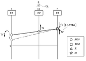
- the vehicle drive device 1 is a drive device for driving a vehicle (hybrid vehicle) including an internal combustion engine E and rotating electrical machines MG1 and MG2 as a driving force source for wheels W. (Hybrid vehicle drive device).
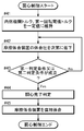
- the vehicle drive device 1 which concerns on this embodiment is provided with the control apparatus 70 (refer FIG. 3), and this control apparatus 70 controls operation
- a broken line indicates a power transmission path
- a solid arrow indicates a transmission path for various information.
- the differential gear device DG provided in the vehicle drive device 1 is constituted by a planetary gear mechanism having a sun gear s, a carrier ca, and a ring gear r as rotating elements.
- the first rotating electrical machine MG1 is drivingly connected to the sun gear s
- the second connecting member 42 is drivingly connected to the carrier ca
- the second rotating electrical machine MG2 is connected to the ring gear r without passing through other rotating elements of the planetary gear mechanism.
- the output member O is drivingly connected.
- the second connecting member 42 is drivingly connected to the internal combustion engine E via the damper device DA and the input member I
- the output member O is drivingly connected to the wheels W.
- the second connecting member 42 and the damper device DA are drivingly connected so as to rotate integrally
- the “intermediate member M” is configured by the second connecting member 42 and the damper device DA.
- the vehicle drive device 1 includes a friction engagement device CL that can release the drive connection between the intermediate member M and the input member I. Further, the vehicle drive device 1 is configured such that the vehicle travels with the torque of the second rotating electrical machine MG2 while the internal combustion engine E is stopped, and the torque of the internal combustion engine E is applied to the first rotating electrical machine MG1 and the output member O. It has a hybrid travel mode (in this example, a split travel mode) in which the vehicle is distributed and travels. When switching from the electric travel mode to the hybrid travel mode, the friction engagement device CL is synchronously engaged from the released state, and the internal combustion engine E is driven by the torque of the first rotating electrical machine MG1 in the direct engagement state of the friction engagement device CL. Control for starting is executed.
- a hybrid travel mode in this example, a split travel mode
- the vehicle drive device 1 according to the present embodiment is input to the intermediate member M, which is a rotating member on both sides of the friction engagement device CL, which is synchronously engaged with the rotation speed being zero. It is characterized in that predetermined alignment control can be executed in order to prevent the eccentric state from being continued when the member I is in an eccentric state.
- predetermined alignment control can be executed in order to prevent the eccentric state from being continued when the member I is in an eccentric state.
- the vehicle drive device 1 includes an input member I drivingly connected to the internal combustion engine E, an output member O drivingly connected to the wheels W, a first rotating electrical machine MG1, a second rotating electrical machine MG2, and an input member I.
- An intermediate member M that is in a power transmission path connecting the output member O and is drivingly connected to the first rotating electrical machine MG1, a differential gear device DG having at least three rotating elements, and a control device 70. Yes.
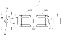
- the vehicle drive device 1 according to the present embodiment distributes the torque of the internal combustion engine E to the first rotating electrical machine MG1 side and the wheels W and the second rotating electrical machine MG2 side. It is configured as a drive device for a so-called two-motor split type hybrid vehicle equipped with DG.
- the vehicle drive device 1 shown in FIG. 1 is suitable as a configuration when mounted on, for example, an FF (Front Engine Front Drive) vehicle.
- the differential gear device DG is constituted by a single pinion type planetary gear mechanism. That is, the differential gear device DG has three rotating elements, specifically, a sun gear s, a carrier ca, and a ring gear r in this example. Then, as described below, the intermediate member M, the output member O, and the first rotating electrical machine MG1 are respectively connected to different rotating elements of the differential gear device DG via other rotating elements of the differential gear device DG. It is connected without driving. In this example, the first rotating electrical machine MG1 is drivingly connected to the sun gear s, the intermediate member M is drivingly connected to the carrier ca, and the output member O is drivingly connected to the ring gear r.
- the rotational speeds of the three rotating elements of the differential gear device DG are in the order of the sun gear s, the carrier ca, and the ring gear r (see FIG. 4 and the like). Assuming that these three rotating elements of the differential gear device DG are “first rotating element E1”, “second rotating element E2”, and “third rotating element E3” in the order of rotation speed, in this embodiment, the sun gear s Is the first rotating element E1, the carrier ca is the second rotating element E2, and the ring gear r is the third rotating element E3.
- the second rotating electrical machine MG2 is a rotating element of the differential gear device DG other than the first rotating element E1 (sun gear s) and the second rotating element E2 (carrier ca) (in this example, the ring gear r that is the third rotating element E3). ) To the differential gear device DG without being driven through another rotating element. Further, the vehicle drive device 1 includes a second rotating element E2 (carrier ca) and a friction engagement device CL capable of releasing the drive connection between the intermediate member M and the input member I.
- a connecting member that rotates integrally with the rotating element is connected to each rotating element of the differential gear device DG.
- a first connecting member 41 is connected to the sun gear s
- a second connecting member 42 constituting an intermediate member M is connected to the carrier ca
- a third gear is connected to the ring gear r.
- the connecting member 43 is connected.
- the first rotating electrical machine MG1 is drivingly connected to the sun gear s by being drivingly connected to the first connecting member 41.
- the first rotating electrical machine MG1 is drivingly connected to the second connecting member 42 constituting the intermediate member M via the sun gear s and the carrier ca.
- the first rotating electrical machine MG1 is drivably coupled to the second coupling member 42 constituting the intermediate member M without the friction engagement device CL.
- the input member I is drivably coupled to the carrier ca by being drivably coupled to the second coupling member 42 via the friction engagement device CL and the damper device DA.
- the input member I is drivingly connected to the internal combustion engine E without going through the friction engagement device CL.
- the output member O and the second rotating electrical machine MG2 are drivably coupled to the ring gear r by being drivably coupled to the third coupling member 43 via the counter gear mechanism C and the counter drive gear 52.
- the input member I is drivingly connected to the internal combustion engine E.
- the input member I is a shaft member (input shaft).
- the internal combustion engine E is a prime mover that outputs power by combustion of fuel.
- a spark ignition engine such as a gasoline engine or a compression ignition engine such as a diesel engine can be used.
- the input member I is drivingly connected so as to rotate integrally with an output shaft of an internal combustion engine such as a crankshaft of the internal combustion engine E. Therefore, the rotational speed of the input member I becomes equal to the rotational speed of the internal combustion engine E.
- the input member I and the internal combustion engine E are drivably coupled to the intermediate member M via a power input unit mainly composed of the friction engagement device CL and the damper device DA. The configuration of the power input unit will be described later.
- the output member O is drivingly connected to the wheel W.
- the output member O is a gear member, and specifically, a differential input gear provided in the output differential gear device D.
- the output differential gear device D is configured by a differential gear mechanism using a plurality of bevel gears that mesh with each other, and the torque transmitted to the output member O is applied to the left and right wheels W that serve as drive wheels. Distribute.
- a first rotating electrical machine MG1 as a rotating electrical machine includes a first stator St1 fixed to a case (driving device case) CS and a first rotor Ro1 that is rotatably supported on the radially inner side of the first stator St1.
- the first rotor Ro1 is drivingly connected to rotate integrally with the first rotating element E1 (sun gear s in this example) via a first connecting member 41 as a first rotor shaft to which the first rotor Ro1 is fixed.
- the second rotating electrical machine MG2 includes a second stator St2 fixed to the case CS, and a second rotor Ro2 that is rotatably supported on the radially inner side of the second stator St2.
- the second rotor Ro2 is drivingly connected to rotate integrally with the second rotating electrical machine output gear 55 via a second rotor shaft to which the second rotor Ro2 is fixed.
- the first rotating electrical machine MG1 is electrically connected to the power storage device B via the first inverter 4, and the second rotating electrical machine MG2 is connected to the power storage device B via the second inverter 5. Is electrically connected.
- the power storage device B a battery, a capacitor, or the like can be used.
- each of the first rotating electrical machine MG1 and the second rotating electrical machine MG2 has a function as a motor (electric motor) that receives power supplied from the power storage device B and generates power (torque), It is possible to function as a generator (generator) that receives the supply to generate electric power and supplies the generated electric power to the power storage device B.
- the counter gear mechanism C includes a first counter gear 53, a second counter gear 54, and a counter shaft that is coupled so as to rotate integrally.
- the third connecting member 43 has a counter drive gear 52 that meshes with the first counter gear 53.
- the second rotating electrical machine output gear 55 is arranged so as to mesh with the first counter gear 53 at a position different from the counter drive gear 52 in the circumferential direction (the circumferential direction of the first counter gear 53).
- the electric machine MG2 is drivingly connected to the third rotating element E3.
- the output member O is disposed so as to mesh with the second counter gear 54, and is drivingly connected to the third rotating element E3.
- the rotational speed relationships among the third rotating element E3, the second rotating electrical machine MG2, and the output member O are proportional to each other, and the proportionality coefficient (that is, the rotational speed ratio) is It becomes a value corresponding to the number of teeth of the gear interposed therebetween.
- the vehicle drive device 1 includes a hybrid travel mode (split travel mode) in which the vehicle travels with the torque of both the internal combustion engine E and the rotating electrical machines MG1 and MG2, and the rotating electrical machine MG1. , MG2 (in this example, only the second rotating electrical machine MG2) and an electric travel mode in which the vehicle is traveled only by the torque.
- hybrid travel mode split travel mode
- MG2 in this example, only the second rotating electrical machine MG2
- an electric travel mode in which the vehicle is traveled only by the torque.
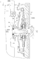
- the power input unit is a mechanism unit for transmitting the torque of the internal combustion engine E transmitted to the input member I to the intermediate member M.
- the power input unit may transmit the torque of the first rotating electrical machine MG1 transmitted to the intermediate member M to the input member I.
- a power input unit is mainly configured by the friction engagement device CL and the damper device DA.
- the power input unit also includes a flywheel 21.
- a flywheel 21 formed in a disk shape is connected to the input member I so as to rotate integrally with the input member I.
- a clutch cover 22 is fixed to the differential gear device DG side (left side in FIG. 2) in the axial direction at the radially outer end of the flywheel 21.
- a pressure plate 23 as a pressing member formed in an annular shape is disposed.
- a radially outer end of a diaphragm spring 25 that is an elastic member is in contact with the pressure plate 23 from the side opposite to the flywheel 21 (the differential gear device DG side).
- the diaphragm spring 25 is supported by a pair of pivot rings 24 held by the clutch cover 22, and presses the pressure plate 23 toward the flywheel 21 (the right side in FIG. 2) by the elastic force of the diaphragm spring 25. Is possible.
- the frictional engagement device CL is provided so as to be able to switch between transmission and interruption of driving force between the flywheel 21 and the damper device DA, thereby selectively drivingly connecting the input member I and the intermediate member M. Is provided.
- the friction engagement device CL according to the present embodiment is configured as a dry single-plate clutch mechanism having a clutch release mechanism including a release fork 32, a diaphragm spring 25, and the like.
- the one end portion of the release fork 32 that is a fork member is divided into two parts so as to sandwich the second connecting member 42.
- the release fork 32 is disposed along the radial direction of the second connecting member 42 and is fixed to the case CS so as to be swingable about a predetermined pivot shaft 33 as a fulcrum.
- a drive motor 31 as a driving force source of the clutch release mechanism of the friction engagement device CL is drivably coupled to a predetermined portion of the release fork 32 opposite to the second coupling member 42 with respect to the pivot shaft 33. ing.
- the drive motor 31 is drivingly connected to the release fork 32 via a mechanism (for example, a mechanism including a ball screw and a nut) that converts the rotational motion into a linear motion.
- Drive motor 31 is driven using the electric power of power storage device B.
- a cylindrical boss Cb formed in the case CS so as to surround the second connecting member 42 is extrapolated in a state where a release bearing 35 as a clutch bearing is held by the cage 34.
- the inner ring of the release bearing 35 is disposed so as to be able to abut on the radially inner end of the diaphragm spring 25.
- the retainer 34 and the release bearing 35 are disposed closer to the flywheel 21 than the release fork 32 and are pushed by the release fork 32 that swings about the pivot shaft 33 as the drive motor 31 is driven. , And can move to the flywheel 21 side along the boss Cb.
- a clutch disk 27 is disposed as a friction member integrally connected to the damper device DA on the radially outer side of the damper device DA.
- the clutch disk 27 has a friction contact portion that contacts each of the pressure plate 23 and the flywheel 21, and the flywheel 21 is sandwiched between the pressure plate 23 and the flywheel 21 with a predetermined engagement pressure.
- the driving force is transmitted to the 21.
- the engagement pressure between the pressure plate 23 and the flywheel 21 can be controlled according to the amount of displacement of the release fork 32 accompanying the drive of the drive motor 31.
- the state indicated by the solid line in FIG. 2 is the “minimum displacement state” in which the displacement amount of the release fork 32 is the minimum (zero), and the state indicated by the two-dot chain line in FIG.
- the maximum amount is the “maximum displacement state”.
- the driving force in the minimum displacement state of the release fork 32, the driving force can be transmitted while the pressure plate 23, the flywheel 21, the clutch disk 27, and the damper device DA rotate integrally by the elastic force of the diaphragm spring 25. It becomes a state. In the present embodiment, this state is referred to as “directly engaged state” of the friction engagement device CL.
- the pressure plate 23, the flywheel 21, the clutch disc 27, and the damper device DA are in a state where the rotation and driving force are not transmitted. In the present embodiment, this state is referred to as a “released state” of the friction engagement device CL.
- this state is referred to as a “slip engagement state” of the friction engagement device CL.
- the damper device DA transmits the rotation of the output shaft of the internal combustion engine to the second connecting member 42 while attenuating the torsional vibration of the output shaft of the internal combustion engine transmitted to the input member I in the direct engagement state of the friction engagement device CL.
- the damper device DA has a cylindrical portion 28 at its radially inner end, and a spline groove is formed on the inner peripheral surface of the cylindrical portion 28.
- the spline groove of the cylindrical portion 28 is engaged with spline teeth formed on the outer peripheral surface of the second connecting member 42. That is, the damper device DA and the second connecting member 42 are drivingly connected so as to rotate integrally through the spline connecting portion 29.
- a predetermined clearance exists between the inner peripheral surface of the cylindrical portion 28 and the outer peripheral surface of the second connecting member 42.
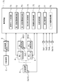
- the control device 70 includes a travel mode determination unit 71, a first rotating electrical machine control unit 72, a second rotating electrical machine control unit 73, an engagement state control unit 74, and synchronous engagement control. Unit 75, start control unit 76, and alignment control unit 77.
- the control device 70 includes an arithmetic processing device such as a CPU as a core, and includes a storage device such as a RAM and a ROM. Each functional unit of the control device 70 is configured by software (program) stored in a ROM or the like, hardware such as a separately provided arithmetic circuit, or both. Each of these functional units is configured to exchange information with each other.
- the control device 70 is configured to be able to acquire information from a sensor or the like provided in each part of the vehicle in order to acquire information of each part of the vehicle on which the vehicle drive device 1 is mounted.
- the control device 70 includes an input member sensor Se1, a second connecting member sensor Se2, a first connecting member sensor Se3, an output member sensor Se4, a power storage state sensor Se10, and an accelerator opening. Information from the sensor Se11 can be acquired.
- the input member sensor Se1 is a sensor that detects the rotational speed of the input member I.
- the second connecting member sensor Se ⁇ b> 2 is a sensor that detects the rotational speed of the second connecting member 42.
- the rotational speed of the second connecting member 42 detected by the second connecting member sensor Se2 is equal to the rotational speed of the second rotating element E2 (carrier ca) of the differential gear device DG.
- the first connecting member sensor Se ⁇ b> 3 is a sensor that detects the rotational speed of the first connecting member 41.
- the rotational speed of the first connecting member 41 detected by the first connecting member sensor Se3 is equal to the rotational speed of the first rotating element E1 (sun gear s) of the first rotating electrical machine MG1 and the differential gear device DG.
- the first connecting member sensor Se3 can be, for example, a rotation sensor (such as a resolver) provided in the first rotating electrical machine MG1.
- the output member sensor Se4 is a sensor that detects the rotation speed of the output member O.
- the control device 70 can derive the vehicle speed based on the rotation speed of the output member O detected by the output member sensor Se4.
- the output member sensor Se4 may be any sensor that can detect the rotational speed of any member that rotates at a rotational speed proportional to the rotational speed of the output member O. Therefore, for example, it is preferable to use a rotation sensor (such as a resolver) provided in the second rotating electrical machine MG2.
- the accelerator opening sensor Se11 is a sensor that detects the accelerator opening by detecting an operation amount of an accelerator pedal (not shown).
- the power storage state sensor Se10 is a sensor that detects the state of the power storage device B (such as the amount of power storage). In the present embodiment, the power storage state sensor Se10 includes a voltage sensor, a current sensor, and the like, and detects the amount of power stored by detecting SOC (state of charge).
- the vehicle is provided with an internal combustion engine control unit 3.
- the internal combustion engine control unit 3 controls the operation of the internal combustion engine E by controlling each part of the internal combustion engine E.
- the internal combustion engine control unit 3 sets a target torque and a target rotational speed as control targets for the torque and rotational speed of the internal combustion engine E, and operates the internal combustion engine E according to the control target, thereby operating the internal combustion engine E.
- the target torque and the target rotation speed are set based on a command from the control device 70.
- the internal combustion engine control unit 3 changes the internal combustion engine E in the stopped state (combustion stopped state) to the start state and changes the internal combustion engine E in the start state to the stopped state in accordance with a command from the control device 70.
- the travel mode determination unit 71 is a functional unit that determines the travel mode of the vehicle.
- the traveling mode determination unit 71 includes a vehicle speed derived based on the detection result of the output member sensor Se4, an accelerator opening detected by the accelerator opening sensor Se11, and a storage state detected by the storage state sensor Se10.
- the driving mode to be realized by the vehicle drive device 1 is determined based on the above.
- the travel modes that can be determined by the travel mode determination unit 71 include a hybrid travel mode and an electric travel mode.
- the travel mode determination unit 71 refers to a mode selection map (not shown) that preliminarily stores and defines the relationship between the vehicle speed, the accelerator opening, and the storage state (storage amount) and the travel mode. To determine the driving mode.
- the hybrid travel mode is a travel mode in which the vehicle travels with the torque of both the internal combustion engine E and the rotating electrical machines MG1, MG2.
- the hybrid travel mode according to the present embodiment is a split travel mode, in which the friction engagement device CL is in a direct engagement state, and the torque of the internal combustion engine E transmitted via the input member I and the intermediate member M is differential.
- the gear device DG is transmitted to the output member O while being distributed to the first rotary electric machine MG1.
- the internal combustion engine E is controlled in such a way as to be maintained in a state with high efficiency and low exhaust gas (a state in accordance with optimum fuel consumption characteristics), and a positive torque corresponding to a required driving force for traveling the vehicle.
- the first rotating electrical machine MG1 outputs a torque in the negative direction and transmits it to the first rotating element E1, and functions as a reaction force receiver for the torque of the internal combustion engine E.
- the torque attenuated with respect to the torque of the internal combustion engine E is transmitted to the output member O that is drivingly connected to the third rotating element E3. As a result, the vehicle is caused to travel.
- the first rotating electrical machine MG1 basically generates power by rotating in the positive direction while outputting a torque in the negative direction.
- the second rotating electrical machine MG2 assists the torque transmitted to the output member O by outputting a positive torque as necessary.
- the first rotating electrical machine MG1 may rotate negatively while outputting torque in the negative direction, and the second rotating electrical machine MG2 may generate electric power for driving the first rotating electrical machine MG1. is there.
- the vehicle can travel while generating power using the large torque of the internal combustion engine E while driving the internal combustion engine E efficiently.
- the electric travel mode is a travel mode that travels only by the torque of the second rotating electrical machine MG2.
- the friction engagement device CL is released, and only the torque of the second rotating electrical machine MG2 is transmitted to the output member O when the internal combustion engine E is stopped.
- torque is not transmitted via the first rotating element E1 and the second rotating element E2, and only the torque of the second rotating electrical machine MG2 that is drivingly connected to the third rotating element E3 is also the third. It is transmitted to the output member O that is drivingly connected to the rotating element E3.
- Second rotating electrical machine MG2 outputs a torque corresponding to the required driving force to drive the vehicle.
- the rotational speed of the first rotating electrical machine MG1 is substantially zero, and the internal combustion engine E is disconnected from the wheels W in the released state of the friction engagement device CL, so that the first rotating electrical machine MG1 is idling. It is possible to improve energy efficiency by avoiding (dragging).
- the transition to the hybrid traveling mode is determined.
- the internal combustion engine start condition is a condition for starting the internal combustion engine E in a stopped state, and is satisfied when the vehicle is in a situation that requires the torque of the internal combustion engine E.
- the driver strongly depresses the accelerator pedal.
- the internal combustion engine start condition is satisfied.
- the internal combustion engine start condition is satisfied.
- the synchronous engagement control unit 75 and the start control unit 76 cooperate to start the internal combustion engine E with the torque of the first rotating electrical machine MG1. This point will be described later.
- the shift to the electric travel mode is determined.
- the internal combustion engine stop condition is satisfied when the vehicle does not need the torque of the internal combustion engine E.
- the friction engagement device CL is released, and then the internal combustion engine E and the first rotating electrical machine MG1 are stopped (the internal combustion engine E and the first engine).
- the rotational speed of the single-rotary electric machine MG1 is zero).
- the first rotating electrical machine control unit 72 as the rotating electrical machine control unit is a functional unit that performs operation control of the first rotating electrical machine MG1. Specifically, the first rotating electrical machine control unit 72 commands a target torque and a target rotational speed as control targets for the torque and rotational speed of the first rotating electrical machine MG1, and the first rotating electrical machine MG1 according to the control target.
- the first inverter 4 is controlled so as to operate.
- the first rotating electrical machine control unit 72 performs operation control of the first rotating electrical machine MG1 by torque control or rotational speed control.
- the torque control is a control for instructing a target torque for the first rotating electrical machine MG1 so that the torque of the first rotating electrical machine MG1 matches the target torque.
- the rotational speed control is a control for instructing a target rotational speed for the first rotating electrical machine MG1 so that the rotational speed of the first rotating electrical machine MG1 coincides with the target rotational speed.
- the second rotating electric machine control unit 73 is a functional unit that controls the operation of the second rotating electric machine MG2. Specifically, the second rotating electrical machine control unit 73 commands a target torque and a target rotational speed as control targets for the torque and rotational speed of the second rotating electrical machine MG2, and the second rotating electrical machine MG2 according to the control target.
- the second inverter 5 is controlled so as to operate.
- the second rotating electrical machine control unit 73 controls the operation of the second rotating electrical machine MG2 by torque control or rotational speed control.
- the torque control is a control in which a target torque for the second rotating electrical machine MG2 is commanded so that the torque of the second rotating electrical machine MG2 matches the target torque.
- the rotational speed control is a control for instructing a target rotational speed for the second rotating electrical machine MG2 so that the rotational speed of the second rotating electrical machine MG2 matches the target rotational speed.
- the second rotating electrical machine control unit 73 controls the second rotating electrical machine MG2 so that the torque transmitted to the output member O becomes a torque corresponding to the required driving force for driving the vehicle.
- the second rotating electrical machine control unit 73 controls the torque of the second rotating electrical machine MG ⁇ b> 2 so that a torque that compensates for a shortage of the torque of the internal combustion engine E is transmitted to the output member O.
- the second rotating electrical machine control unit 73 controls the torque of the second rotating electrical machine MG2 so that the torque that matches the required driving force is transmitted to the output member O.
- the engagement state control unit 74 is a functional unit that controls the state of the friction engagement device CL.
- the engagement state control unit 74 controls the operation of the drive motor 31 provided as a driving force source of the clutch release mechanism of the friction engagement device CL, thereby changing the state of the friction engagement device CL. Control.
- the engagement state control unit 74 controls the engagement pressure of the friction engagement device CL by controlling the rotational speed and drive time of the drive motor 31 to control the displacement amount of the release fork 32.
- the friction engagement device CL is controlled to any one of the released state, the direct connection engagement state, and the slip engagement state.
- the engagement state control unit 74 controls the state of the friction engagement device CL according to the travel mode determined by the travel mode determination unit 71. For example, the engagement state control unit 74 sets the friction engagement device CL to the direct engagement state when the hybrid travel mode is selected, and sets the friction engagement device CL to the release state when the electric travel mode is selected. In addition, the engagement state control unit 74 is frictionally engaged in accordance with a command from the alignment control unit 77 so that the slip engagement state is temporarily set in the transition process between the hybrid travel mode and the electric travel mode as described later. Control device CL.
- the synchronous engagement control unit 75 is a functional unit that executes synchronous engagement control in which the friction engagement device CL is engaged (synchronously engaged) in a synchronized state to be in a directly connected state. .
- the synchronous engagement control unit 75 executes this synchronous engagement control when the internal combustion engine start condition is satisfied in the released state of the friction engagement device CL.
- the traveling mode determining unit 71 determines to switch the traveling mode from the electric traveling mode to the hybrid traveling mode
- the synchronous engagement control unit 75 acquires a differential rotational speed ⁇ N between the input member I and the intermediate member M, which are rotary members on both sides of the friction engagement device CL.
- the differential rotation speed ⁇ N is obtained by subtracting the rotation speed of the input member I detected by the input member sensor Se1 from the rotation speed of the second connection member 42 (intermediate member M) detected by the second connection member sensor Se2. It can be calculated and obtained as the subtracted value.
- the internal combustion engine E is stopped during traveling in the electric traveling mode, and its rotational speed is zero.
- the synchronous engagement control unit 75 is in the state where the second connection member 42 (intermediate member) detected by the second connection member sensor Se2 is in a state where the vehicle is traveling in the electric travel mode and before the internal combustion engine E starts to rotate.
- the rotational speed of M) can be obtained as it is as the differential rotational speed ⁇ N.
- the synchronous engagement control unit 75 instructs the first rotating electrical machine control unit 72 to change the rotational speed of the first rotating electrical machine MG1 so as to reduce the differential rotational speed ⁇ N.
- the synchronous engagement control unit 75 sets the differential rotation speed ⁇ N to be equal to or less than the synchronization determination threshold value ⁇ Ns1 based on the acquired differential rotation speed ⁇ N and a preset synchronization determination threshold value ⁇ Ns1 (see FIG. 8). In this case, it is determined that the state is “synchronized state”.
- the synchronous engagement control unit 75 controls the operation of the drive motor 31 by instructing the engagement state control unit 74 on the condition that the input member I and the intermediate member M are in a synchronized state, and the friction engagement device CL. Is switched from the released state to the directly connected state.
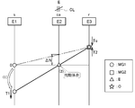
- each speed diagram referred to in the following description corresponds to the rotational speed of each rotating element. That is, “0” appended to the vertical axis indicates that the rotation speed is zero, and the upper side is positive rotation (rotation speed is positive) and the lower side is negative rotation (rotation speed is negative). Further, each of the plurality of vertical lines arranged in parallel corresponds to each rotation element of the differential gear device DG. Further, on the speed diagram, the rotational speed of the first rotating electrical machine MG1, the rotational speed of the second rotating electrical machine MG2, the rotational speed of the internal combustion engine E (input member I), and the rotational speed of the output member O are mutually different. Shown with different symbols. In addition, in order to make an understanding of invention easy, regarding the rotational speed of the 2nd rotary electric machine MG2 and the output member O, the rotational speed transmitted to the 3rd rotation element E3 is shown.
- T1 indicates the torque of the first rotating electrical machine MG1 transmitted to the first rotating element E1 (sun gear s), and “T2” indicates the second rotating electrical machine transmitted to the third rotating element E3 (ring gear r).
- the torque of MG2 is shown.
- Te indicates the torque of the internal combustion engine E transmitted to the second rotating element E2 (carrier ca) via the friction engagement device CL in the directly coupled state, and “To” indicates from the output member O (wheel W).
- the running torque (running resistance) transmitted to the third rotating element E3 is shown. In the arrows arranged adjacent to these torques, an upward arrow indicates a positive torque, and a downward arrow indicates a negative torque.
- the operating state of the differential gear device DG in the electric travel mode is indicated by a two-dot chain line.
- the friction engagement device CL is released, and the internal combustion engine E is disconnected from the second rotating element E2 of the differential gear device DG.
- the 2nd rotation element E2 will be in the state which can rotate freely.
- the rotation speed of the first rotating electrical machine MG1 is set to zero
- the second rotating element E2 is set to the rotational speed of the third rotating element E3 determined according to the vehicle speed and the rotating speed of the first rotating electrical machine MG1 (here, zero). )
- the synchronous engagement control unit 75 reduces the rotation speed of the second rotation element E2 connected so as to decrease the differential rotation speed ⁇ N, that is, to rotate integrally with the intermediate member M.
- the single-rotary electric machine MG1 is caused to output a torque in the negative direction to reduce the rotational speed from zero.
- the third rotating element E3 determined according to the vehicle speed is maintained at a substantially constant rotational speed.
- the rotation speed of the second rotation element E2 gradually decreases with the rotation element E3 as a fulcrum.
- the synchronous engagement control unit 75 is in a synchronized state. judge.
- a preset synchronization determination threshold value ⁇ Ns1 for example, a value of 0 to 50 [rpm] can be set, and in this example, it is set to 0 [rpm].
- the synchronous engagement control unit 75 detects that the rotation speeds of the second rotation element E2 and the intermediate member M have decreased to zero before long, the synchronous engagement control unit 75 determines that the synchronization is in the synchronized state, The friction engagement device CL is brought into a direct engagement state via the control unit 74.
- the operating state of the differential gear device DG in this synchronized state is indicated by a solid line.
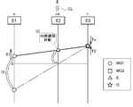
- the start control unit 76 is a functional unit that executes internal combustion engine start control for starting the internal combustion engine E by increasing the rotation speed of the input member I by the torque of the first rotating electrical machine MG1.
- the start control unit 76 performs the internal combustion engine start control with the friction engagement device CL in the directly connected state. That is, after the friction engagement device CL is brought into the direct engagement state by the synchronous engagement control unit 75 executing the synchronous engagement control, the direct engagement state of the friction engagement device CL is maintained, The start control unit 76 executes internal combustion engine start control.
- the rotational speed of the first rotating electrical machine MG1 is changed so as to have a rotational speed at which the internal combustion engine E can be started.
- the start control unit 76 instructs the first rotating electrical machine control unit 72 to change the rotation speed of the first rotating electrical machine MG1 in the direction opposite to the direction of change in the synchronous engagement control.
- the first rotating electrical machine MG1 outputs negative torque to reduce the rotational speed (see FIG. 4), whereas the internal combustion engine start control by the start control unit 76 is performed. Then, the first rotating electrical machine MG1 outputs a torque in the positive direction to increase the rotational speed (see FIG. 5).
- the operating state of the differential gear device DG in the synchronized state is indicated by a two-dot chain line. If the rotational speed of the first rotating electrical machine MG1 is increased by the internal combustion engine start control from this state, the rotational speed of the first rotating element E1 also increases as the rotational speed of the first rotating electrical machine MG1 increases. Then, the rotation speed of the second rotation element E2 gradually increases with the third rotation element E3 as a fulcrum while the rotation speed of the third rotation element E3 determined according to the vehicle speed is maintained substantially constant.
- the rotation speed control of the first rotating electrical machine MG1 is executed in the internal combustion engine start control. That is, in the internal combustion engine start control, the first rotating electrical machine control unit 72 commands the target rotational speed for the first rotating electrical machine MG1, and executes control to make the rotational speed of the first rotating electrical machine MG1 coincide with the target rotational speed. .
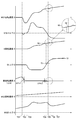
- the target rotational speed of the first rotating electrical machine MG1 is set to the rotational speed of the first rotating electrical machine MG1 that makes the rotational speed of the internal combustion engine E startable (ignition rotational speed Nf; see FIG. 8).
- the first rotating electrical machine MG1 outputs a large positive torque. Thereafter, as the rotational speed of the internal combustion engine E increases, such load torque decreases over time, and the torque of the first rotating electrical machine MG1 for maintaining the target rotational speed gradually decreases (see FIG. 8).
- the start control unit 76 determines that the internal combustion engine E can be ignited, and instructs the internal combustion engine control unit 3 to The internal combustion engine E is started.
- the ignition rotational speed Nf is a rotational speed at which the internal combustion engine E can be ignited and started (for example, a rotational speed during idling), and in this example, is higher than an alignable rotational speed NI described later. A large value is set (see FIG. 8).
- the internal combustion engine E when the internal combustion engine E is started by the internal combustion engine start control and starts a self-sustaining operation, the internal combustion engine E starts to output a positive torque. Then, the positive torque of the internal combustion engine E is transmitted to the first rotating electrical machine MG1 via the friction engagement device CL and the differential gear device DG, and the rotational speed of the first rotating electrical machine MG1 tends to increase.
- the rotation speed control of the first rotating electrical machine MG1 is executed in the internal combustion engine start control, and in this embodiment, the rotation speed control is continuously executed even after the internal combustion engine E is started. Therefore, the first rotating electrical machine control unit 72 outputs the torque in the direction opposite to that at the start of the internal combustion engine E so that the rotational speed of the first rotating electrical machine MG1 matches the target rotational speed. Control MG1.
- the first rotating electrical machine control unit 72 outputs the torque in the positive direction to the first rotating electrical machine MG1 to increase the rotational speed before the internal combustion engine E is started, whereas the internal combustion engine E After starting, the first rotating electrical machine MG1 is caused to output a torque in the negative direction so that its rotational speed matches the target rotational speed.
- the direction of the torque of the first rotating electrical machine MG1 is reversed from the positive direction to the negative direction before and after the internal combustion engine E is started and starts the self-sustaining operation. Thereby, it is possible to smoothly shift to the hybrid travel mode with the execution of the internal combustion engine start control and the rotational speed control of the first rotating electrical machine MG1 that are performed simultaneously.
- the mode switching from the electric travel mode to the hybrid travel mode is performed by the synchronous engagement control unit 75 through the stopped state of the internal combustion engine E and the synchronized state of the input member I and the intermediate member M.
- Both the input member I and the intermediate member M have an aspect in which the rotational speed is zero. Therefore, the input member I and the intermediate member M can be in an eccentric state. That is, in this embodiment, the intermediate member M is constituted by the second connecting member 42 and the damper device DA, and these are driven and connected to rotate integrally through the spline connecting portion 29 as shown in FIG. Yes.
- a predetermined clearance exists between the inner peripheral surface of the cylindrical portion 28 of the damper device DA and the outer peripheral surface of the second connecting member 42 in the spline connecting portion 29. Therefore, when the rotational speed of the intermediate member M is zero, at least the shaft center adjustment function due to the rotation of the damper device DA itself does not work, and the damper device DA moves vertically downward by its own weight and the clearance is uneven. It becomes a state. In other words, the clearance vertically below the second connecting member 42 is larger than the clearance vertically above the second connecting member 42.
- the input member I is always maintained in good axial accuracy through an input bearing (not shown), and the second connecting member 42 constituting the intermediate member M is also an intermediate bearing (see FIG.
- the axial center accuracy is always maintained well through (not shown). Therefore, when the rotational speed of the intermediate member M is zero and only the damper device DA is moving vertically downward, the input member I and the intermediate member M are in an eccentric state as a whole.
- the frictional engagement device CL is brought into the direct engagement state in this state, the radial position is constrained by the frictional engagement device CL while the input member I and the intermediate member M are eccentric from each other. become.
- the control device 70 When the vehicle continues to run while the eccentric state is maintained, the input member I and the intermediate member M which are in an eccentric state sway and vibrate as a whole. There is a possibility that the load acting on the intermediate bearing that supports the two connecting members 42 becomes large. Therefore, in order to suppress such an eccentric state from being maintained, the control device 70 according to the present embodiment includes an alignment control unit 77.
- the alignment control unit 77 adjusts the friction engagement device CL as a slip engagement state temporarily while the internal combustion engine E is rotating at a rotation speed equal to or higher than a predetermined rotation speed. It is a functional unit that performs heart movement (alignment control).
- an alignment operation when the engagement pressure of the friction engagement device CL is decreased and it is detected that the differential rotational speed ⁇ N between the input member I and the intermediate member M is equal to or greater than the slip determination threshold ⁇ Ns2, friction is detected.
- the operation for returning the engagement device CL to the direct engagement state is referred to as “alignment operation”.
- the “internal combustion engine rotation state” is a state in which the rotation speed of the internal combustion engine E is equal to or higher than the alignable rotation speed NI set to a value smaller than the ignition rotation speed Nf in the present embodiment. That is, the alignment control unit 77 performs alignment operation in a state where at least the rotation speed of the internal combustion engine E is equal to or higher than the rotation speed NI that can be aligned.
- the alignable rotation speed NI is set in advance to a rotation speed that is equal to or higher than a rotation speed (for example, 200 [rpm]) at which the internal combustion engine E and the input member I can exhibit the shaft center adjustment function.
- the alignable rotation speed NI is set to a value slightly smaller than the ignition rotation speed Nf (see FIG. 8).
- the alignment control unit 77 further performs alignment operation after the torque of the internal combustion engine E becomes equal to or higher than a predetermined start determination torque TI.
- a start determination torque TI is set in advance as a torque when the internal combustion engine E starts a self-sustained operation and the internal combustion engine E starts outputting torque.
- the rotational speed of the internal combustion engine E is equal to or higher than the ignition rotational speed Nf, and the rotational speed of the internal combustion engine E is higher than the alignable rotational speed NI.
- the alignment operation can be reliably performed in the rotation state of the internal combustion engine. Moreover, when performing the alignment operation, there is also an advantage that the shaft center adjustment function can be operated by utilizing the rotation and torque of the internal combustion engine E that has started the independent operation.
- the alignment control unit 77 further detects a torque reversal in which the direction of the torque of the first rotating electrical machine MG1 is reversed while the rotational speed control of the first rotating electrical machine MG1 is being performed. Then, after detecting the torque reversal, the alignment operation is performed.
- the alignment control unit 77 can detect torque reversal by monitoring the command value of the target torque for the first rotating electrical machine MG1 output from the first rotating electrical machine control unit 72.
- the alignment control unit 77 starts the alignment operation when detecting the torque reversal in which the direction of the torque of the first rotating electrical machine MG1 is reversed. That is, the alignment control unit 77 detects torque reversal, and at the same time, instructs the engagement state control unit 74 to control the operation of the drive motor 31 to apply the engagement pressure of the friction engagement device CL (the clutch disk 27 The engagement pressure between the pressure plate 23 and the flywheel 21 to be sandwiched is reduced.
- the engagement pressure of the friction engagement device CL is relatively large, the restraining force due to the engagement pressure is large, and the restraining force is superior to the swinging torque due to the eccentricity between the input member I and the intermediate member M. Therefore, the friction engagement device CL is maintained in the direct engagement state, and the radial positions of the input member I and the intermediate member M are maintained as they are due to the engagement pressure of the friction engagement device CL.
- the flywheel 21 and the pressure plate 23 A slip occurs with the clutch disk 27. That is, the friction engagement device CL is in the slip engagement state.
- the internal combustion engine is already rotating when this slip occurs, and in this embodiment, the input member I and the intermediate member M are rotating at a rotational speed sufficiently higher than the alignable rotational speed NI. Therefore, while the friction engagement device CL is in the slip engagement state, that is, while the restraining force due to the engagement pressure of the friction engagement device CL is loosened, the rotation of the input member I and the intermediate member M respectively.
- the shaft center adjustment function can be activated.
- the shaft center adjusting function by the rotation of the damper device DA constituting the intermediate member M can be operated. That is, the clearance between the inner peripheral surface of the cylindrical portion 28 of the damper device DA and the outer peripheral surface of the second connecting member 42 can be equalized and aligned over the entire periphery. Thereby, it is possible to prevent the eccentric state between the input member I and the intermediate member M, which are rotating members on both sides of the friction engagement device CL, from continuing.
- the alignment control unit 77 determines completion of the shaft center adjustment based on the differential rotational speed ⁇ N between the input member I and the intermediate member M on both sides of the friction engagement device CL.
- the alignment control unit 77 refers to the completion determination condition defined based on the differential rotation speed ⁇ N and a slip determination threshold value ⁇ Ns2 (see FIG. 8) as a preset differential rotation threshold value. Determine completion.
- the completion determination condition is “the rotation speed of the input member I detected by the input member sensor Se1 from the rotation speed of the second connection member 42 (intermediate member M) detected by the second connection member sensor Se2.
- the difference rotational speed ⁇ N calculated as a subtracted value obtained by subtracting “S” is set to the slip determination threshold value ⁇ Ns2 or more ”.
- the slip determination threshold value ⁇ Ns2 for example, a value of 30 to 100 [rpm] can be set. According to such a completion determination condition, it can be directly determined that a slip actually occurs between the input member I and the intermediate member M and the shaft center adjusting function is activated.
- Alignment control unit 77 returns friction engagement device CL to the direct engagement state after determining that the shaft center adjustment has been completed.
- the alignment control unit 77 instructs the engagement state control unit 74 to control the operation of the drive motor 31 at the same time as the completion of the shaft center adjustment, thereby increasing the engagement pressure of the friction engagement device CL again.
- the friction engagement device is brought into a direct engagement state. Accordingly, the input member I and the intermediate member M (the input member I, the damper device DA, and the second member) that are in a good alignment state in a state where the restraining force due to the engagement pressure of the friction engagement device CL is loosened.
- the connecting member 42) is restrained in the radial position by the frictional engagement device CL while maintaining its good alignment state.
- the friction engagement device CL is engaged.
- the frictional engagement device CL is detected after detecting that a predetermined differential rotational speed ⁇ N is generated between the input member I and the intermediate member M by temporarily reducing the restraining force due to the engagement pressure by lowering the pressure. Return to the direct engagement state again.
- the restraining force of the radial position between the input member I and the intermediate member M is temporarily loosened, and the eccentricity of these shafts is adjusted by using the function of adjusting the shaft center by the rotation of the input member I and the intermediate member M in the meantime. It can suppress that a state continues. Further, after the input member I and the intermediate member M are brought into a good alignment state, the restraining force at the radial position between them is increased again in that state, and the good alignment state is continued. Can do.
- the engagement pressure of the friction engagement device CL is reduced during the aligning operation, and the friction engagement device CL is actually in the slip engagement state and transmitted from the internal combustion engine E side through the friction engagement device CL.
- the rotational speed of the first rotating electrical machine MG1 is reduced by the negative torque of the first rotating electrical machine MG1. That is, the operation state of the differential gear device DG is a state indicated by a two-dot chain line in FIG.
- the alignment control unit 77 starts the alignment operation at the same time as detecting the torque reversal in which the direction of the torque of the first rotating electrical machine MG1 is reversed.
- the torque of the first rotating electrical machine MG1 becomes zero. Further, the absolute value of the torque of the first rotating electrical machine MG1 remains a relatively small value close to zero during a predetermined period including the time of torque reversal, which is a period during which the alignment operation is performed.
- the first rotating electrical machine is driven by the negative torque of the first rotating electrical machine MG1.
- the extent to which the rotational speed of MG1 is reduced can be kept relatively small. Therefore, it is possible to suppress fluctuations in the rotational speed of the intermediate member M that is drivingly connected to the first rotating electrical machine MG1 via the first rotating electrical machine MG1 and the differential gear device DG. Further, even when the engagement pressure of the frictional engagement device CL is increased again after alignment to return the frictional engagement device CL to the direct engagement state, fluctuations in the rotational speed of the internal combustion engine E are suppressed. Can do.
- the first rotating electrical machine control unit 72 continues to execute the rotational speed control of the first rotating electrical machine MG1. Therefore, when the rotational speed of the first rotating electrical machine MG1 decreases in the slip engagement state of the friction engagement device CL as described above in accordance with the aligning operation, the first rotating electrical machine control unit 72 rotates the first rotating electrical machine MG1.
- the torque of the first rotating electrical machine MG1 is controlled so as to increase the speed. That is, the first rotating electrical machine control unit 72 outputs an instruction to reduce the absolute value of the negative torque output by the first rotating electrical machine MG1, thereby reducing the absolute value of the negative torque of the first rotating electrical machine MG1. Make it smaller.
- the second rotating electrical machine control unit 73 compensates for the decrease caused by continuing the rotational speed control of the first rotating electrical machine MG1 of the torque transmitted to the output member O, and cancels the decrease. Increase the torque of the rotating electrical machine MG2. Thereby, the torque change transmitted to the output member O can be suppressed, and it can suppress giving a discomfort to the passenger
- FIG. 8 is a flowchart showing the entire processing procedure of the mode switching control
- FIG. 10 is a flowchart showing the processing procedure of the alignment control in step # 09.
- traveling mode determination unit 71 determines whether or not the internal combustion engine start condition is satisfied (step # 01 in FIG. 9).
- step # 01 the internal combustion engine start condition is satisfied at time T01 (step # 01: Yes)
- synchronous engagement control is executed from time T01 to time T02.
- the synchronous engagement control unit 75 instructs the first rotating electrical machine control unit 72 to reduce the differential rotational speed ⁇ N between the input member I and the intermediate member M and to obtain a predetermined synchronization determination threshold value.
- the rotational speed of the first rotating electrical machine MG1 is changed so as to be equal to or less than ⁇ Ns1 (zero in this example) (step # 02).
- the rotation speed control of the first rotating electrical machine MG1 is continuously executed until the difference rotation speed ⁇ N becomes equal to or less than the synchronization determination threshold value ⁇ Ns1 (step # 03: No).
- the differential rotation speed ⁇ N reaches the synchronization determination threshold value ⁇ Ns1 at time T02 (step # 03: Yes)
- it is determined that the synchronization state is reached step # 04
- the synchronization engagement control unit 75 performs the engagement state control.
- the unit 74 is commanded to place the frictional engagement device CL in the direct engagement state (step # 05).
- the start control unit 76 starts the internal combustion engine start control at time T03 after a predetermined time has elapsed since the friction engagement device CL is brought into the direct engagement state (step # 06).
- the rotation speed of the first rotating electrical machine MG1 is increased from time T03 to T04 so that the rotation speed is such that the internal combustion engine E can be started.
- the rotation speed of the first rotating electrical machine MG1 is controlled, and the rotation speed of the internal combustion engine E is gradually increased while outputting torque against the load torque of the internal combustion engine E.
- the second rotating electrical machine control unit 73 corrects the torque change transmitted to the output member O via the differential gear device DG due to the torque output by the first rotating electrical machine MG1 and the load torque of the internal combustion engine E.
- the torque of the second rotating electrical machine MG2 is controlled so as to cancel out.
- the alignment control unit 77 monitors the change state of the torque direction of the first rotating electrical machine MG1. Specifically, the alignment control unit 77 monitors whether or not the sign of the target torque command value for the first rotating electrical machine MG1 has been reversed from positive to negative (step # 07). When it is detected that the direction of torque of the first rotating electrical machine MG1 is reversed at time T04 (step # 07: Yes), it is determined that the internal combustion engine E has started (step # 08). In the present embodiment, it is determined that the internal combustion engine is in a rotating state based on the start determination of the internal combustion engine E. If the start determination of the internal combustion engine E is made, then alignment control is executed (step # 09).
- the alignment control unit 77 instructs the engagement state control unit 74 from time T04 to control the operation of the drive motor 31, and gradually decreases the engagement pressure of the friction engagement device CL (step). # 21). Further, the first rotating electrical machine control unit 72 continuously executes the rotational speed control of the first rotating electrical machine MG1 during the alignment control (step # 22). Along with this rotational speed control of the first rotating electrical machine MG1, the torque transmitted to the output member O when the friction engagement device CL enters the slip engagement state changes. The second rotating electrical machine MG2 is controlled so as to correct the torque change transmitted to the output member O in accordance with the rotational speed control of the first rotating electrical machine MG1 (step # 23).
- step # 24 No.
- step # 24: Yes when the differential rotational speed ⁇ N reaches the slip determination threshold value ⁇ Ns2 at time T05 (step # 24: Yes), it is determined that the adjustment of the shaft center is completed (step # 25).
- the alignment control unit 77 instructs the engagement state control unit 74 from time T05 to control the operation of the drive motor 31, and gradually increases the engagement pressure of the friction engagement device CL.
- the friction engagement device CL is brought into the direct engagement state (step # 26).
- the rotational speed of the first rotating electrical machine MG1 temporarily decreases when the friction engagement device CL is temporarily brought into the slip engagement state, but the rotation of the first rotating electrical machine MG1 is controlled by the rotational speed control. The speed increases again, and when it matches the target rotational speed at time T06, the alignment control is terminated. Further, after that, when the torque of the internal combustion engine E reaches the ignition determination torque Tf for stable self-sustained operation at time T07, the internal combustion engine start control is terminated, and the mode switching control is also terminated accordingly. The above processing is executed for each travel in the electric travel mode.
- the vehicle drive device 1 according to the present embodiment is different from the configuration of the first embodiment mainly in the method of determining completion of shaft center adjustment by the alignment control unit 77 and the related configuration. Below, the structure of the vehicle drive device 1 which concerns on this embodiment is demonstrated centering on difference with said 1st embodiment. Note that points not particularly described are the same as those in the first embodiment.
- the alignment control unit 77 determines the completion of the shaft center adjustment based on the differential rotational speed ⁇ N between the input member I and the intermediate member M at least as in the first embodiment. In the present embodiment, the alignment control unit 77 further determines whether or not the shaft center adjustment is complete based on the rotational speed of the first rotating electrical machine MG1. That is, the alignment control unit 77 determines whether or not the shaft center adjustment is completed when at least one of the first determination condition based on the differential rotation speed ⁇ N and the second determination condition based on the rotation speed of the first rotating electrical machine MG1 is satisfied.
- the first determination condition is the same as the completion determination condition described in the first embodiment, specifically, “the second connection member 42 (intermediate member M detected by the second connection member sensor Se2). ),
- the difference rotational speed ⁇ N calculated as a subtraction value obtained by subtracting the rotational speed of the input member I detected by the input member sensor Se1 has become equal to or greater than the slip determination threshold value ⁇ Ns2. .
- the alignment control unit 77 maintains the torques of both the first rotating electrical machine MG1 and the internal combustion engine E at constant values.
- the centering operation is performed in the state. Therefore, the control device 70 according to the present embodiment further includes a torque maintenance control unit 78 (indicated by a broken line in FIG. 3).
- the torque maintenance control unit 78 instructs the first rotating electrical machine control unit 72 to maintain the torque of the first rotating electrical machine MG1 at a constant value that does not change over time, and maintains the torque of the internal combustion engine E at a constant value that does not change over time.
- a torque maintenance command for instructing the internal combustion engine control unit 3 to output is output. While the torque maintenance command is output, the command values of the target torque of the first rotating electrical machine MG1 and the internal combustion engine E are fixed to the values at the start of the alignment operation.
- the engagement pressure of the friction engagement device CL is lowered while the torques of both the first rotating electrical machine MG1 and the internal combustion engine E are maintained at a constant value, and the friction engagement device CL is actually in the slip engagement state.
- the torque transmitted from the internal combustion engine E side via the friction engagement device CL decreases, when the first rotating electrical machine MG1 outputs a negative torque, the torque of the first rotating electrical machine MG1 As a result, the rotational speed of the first rotating electrical machine MG1 decreases. Therefore, by detecting an event that the rotation speed of the first rotating electrical machine MG1 changes (here, decreases), a slip occurs between the input member I and the intermediate member M, and the shaft center adjustment function is activated. It can be easily determined indirectly.
- the second determination condition is specifically set as “the amount of change in the rotation speed of the first rotating electrical machine MG1 is equal to or greater than a predetermined rotation change determination threshold”. ing.
- a rotation change determination threshold may be set in advance, or may be set according to the vehicle speed, the rotation speed of the internal combustion engine E, the magnitude of the torque of the first rotating electrical machine MG1, or the like. good.
- the alignment control unit 77 performs a predetermined value in which the torque of the first rotating electrical machine MG1 is set to a negative value. After the negative torque threshold value is reached, the alignment operation can be started with the torque maintained at a constant value. Alternatively, the alignment control unit 77 maintains the torque at a certain value after a predetermined time has elapsed after the direction of the torque of the first rotating electrical machine MG1 is reversed when the internal combustion engine E is started, for example. For example, the alignment operation may be started in the state.
- FIG. 11 is a flowchart showing a processing procedure of alignment control according to the present embodiment.
- the alignment control unit 77 instructs the torque maintenance control unit 78 to maintain the torque of the internal combustion engine E and the torque of the first rotating electrical machine MG1 at constant values (step #). 41).
- the alignment control unit 77 instructs the engagement state control unit 74 to control the operation of the drive motor 31, and gradually decreases the engagement pressure of the friction engagement device CL (step # 42).
- step # 43: Yes it is determined that the adjustment of the axis is completed (step # 44).
- the alignment control unit 77 instructs the engagement state control unit 74 to control the operation of the drive motor 31 to gradually increase the engagement pressure of the friction engagement device CL.
- the friction engagement device CL is brought into the direct coupling engagement state (step # 45). This completes the alignment control.
- the alignable rotation speed NI is set to a value slightly smaller than the ignition rotation speed Nf.
- the embodiment of the present invention is not limited to this. That is, the alignable rotation speed NI only needs to be set to a value that is at least equal to or higher than the rotation speed at which the internal combustion engine E and the input member I can exhibit the shaft center adjustment function, and is sufficiently smaller than the ignition rotation speed Nf. It is one of the preferred embodiments of the present invention to set or set to a value equal to or higher than the ignition rotation speed Nf.
- the embodiment of the present invention is not limited to this. That is, in the case where the alignable rotation speed NI is set to a value smaller than the ignition rotation speed Nf, for example, the adjustment is performed in a state in which the internal combustion engine is rotating and the rotation speed of the internal combustion engine E is less than the ignition rotation speed Nf.
- a configuration in which the heart control is executed is also a preferred embodiment of the present invention.
- the internal combustion engine E has not yet operated independently when the rotational speed is less than the ignition rotational speed Nf, but the shaft center adjustment function works at least when the rotational speed is higher than the alignable rotational speed NI. It can suppress that the eccentric state of the member M and the input member I is continued.
- the alignment control unit 77 has been described as an example in which the alignment operation is started at the time of detection of torque reversal in which the direction of the torque of the first rotating electrical machine MG1 is reversed.
- the alignment control unit 77 detects that the torque of the first rotating electrical machine MG1 is equal to or less than a predetermined negative torque threshold set to a negative value, or the torque
- a predetermined negative torque threshold set to a negative value
- the embodiment of the present invention is not limited to this.
- the alignment control unit 77 performs a predetermined time when a predetermined time has elapsed from the detection of torque reversal or when the torque of the first rotating electrical machine MG1 is set to a negative value. It is also a preferred embodiment of the present invention that the alignment operation is started when it is detected that the negative torque threshold value has been reached.
- the alignment control unit 77 monitors the rotational speed of the second connecting member 42 (intermediate member M) detected by, for example, the second connecting member sensor Se2, and the intermediate member It is also a preferred embodiment of the present invention that the alignment operation is started when it is detected that the rotation speed of M has reached the alignable rotation speed NI.
- the alignment control unit 77 may be configured to start the alignment operation after a predetermined time has elapsed after detecting that the rotation speed of the intermediate member M has reached the alignable rotation speed NI. This is one of the preferred embodiments.
- the alignment control unit 77 monitors the torque of the internal combustion engine E using, for example, a torque sensor and the like, and the fact that the torque of the internal combustion engine E has reached the start determination torque TI. It is also a preferred embodiment of the present invention that the alignment operation is started at the time of detection. Alternatively, the alignment control unit 77 may be configured to start the alignment operation after a predetermined time has elapsed after detecting that the torque of the internal combustion engine E has reached the start determination torque TI. This is one of the embodiments.
- the timing at which the alignment control unit 77 starts the alignment operation can be arbitrarily set if at least the rotation speed of the internal combustion engine E is equal to or higher than the rotation speed NI that can be aligned.
- the alignment operation is performed as early as possible (within a predetermined time) after the internal combustion engine is rotated. It is preferable that
- the alignment control unit 77 determines whether or not the shaft center adjustment is completed when at least one of them is satisfied based on both the first determination condition and the second determination condition.
- the embodiment of the present invention is not limited to this.
- the alignment control unit 77 may be configured to determine whether or not the shaft center adjustment is completed based on only one of the first determination condition and the second determination condition.
- One for example, when the alignment control unit 77 monitors only the rotational speed of the first rotating electrical machine MG1 and detects that the rotational speed change amount of the first rotating electrical machine MG1 is equal to or greater than a predetermined rotational change determination threshold. It can be set as the structure which determines with axial center adjustment having been completed.
- the alignment control is executed when the internal combustion engine start condition is satisfied during traveling in the electric traveling mode and the mode is switched from the electric traveling mode to the hybrid traveling mode.
- the application scene of the present invention is not limited to this. That is, for example, in a situation where the internal combustion engine start condition is satisfied when the vehicle is stopped and the internal combustion engine start control is executed through synchronous engagement control, the vehicle is started by the torque of the internal combustion engine E. Can be configured to execute. Even in such a case, as in the above embodiments, even if the intermediate member M and the input member I on both sides of the friction engagement device CL are in an eccentric state, the alignment control is performed. Execution of the eccentric state can be suppressed.
- the intermediate member M is configured by the second connecting member 42 and the damper device DA that are spline-connected to each other, and the input member I and the second connecting member 42 are both bearings.
- the description has been given of the case where the shaft center accuracy is always maintained satisfactorily, and only the damper device DA moves vertically downward and is eccentric while the rotational speed of the intermediate member M is zero.
- the embodiment of the present invention is not limited to this. That is, depending on the shaft support structure of each of the input member I and the intermediate member M, at least one of the shaft centers of the input member I and the intermediate member M may be inclined at a rotational speed of zero, and may be in an eccentric state. There is sex. Therefore, even in such a case, the eccentricity between the intermediate member M and the input member I can be prevented from being continued by performing the alignment control as described in the above embodiments. be able to.
- the friction engagement device CL is configured as a dry single-plate clutch mechanism having a motor-driven clutch release mechanism.
- the embodiment of the present invention is not limited to this. That is, the specific configuration of the friction engagement device CL can be arbitrary.
- configuring the friction engagement device CL as a dry single-plate clutch mechanism having a hydraulically driven or electromagnetically driven clutch release mechanism is also one preferred embodiment of the present invention.
- the first rotating electrical machine MG1 is drivingly connected to the first rotating element E1 of the differential gear device DG, and the intermediate member M and the internal combustion engine E are drivingly connected to the second rotating element E2.
- the case where the output member O and the second rotating electrical machine MG2 are drivingly connected to the third rotating element E3 has been described as an example.
- the embodiment of the present invention is not limited to this. That is, for example, the first rotating electrical machine MG1 is drivingly connected to the first rotating element E1 of the differential gear device DG, the output member O and the second rotating electrical machine MG2 are drivingly connected to the second rotating element E2, and the third rotating element E3.
- the intermediate member M and the internal combustion engine E are connected to each other.
- the hybrid travel mode in which the vehicle travels with the torque of both the internal combustion engine E and the rotating electrical machines MG1, MG2 is basically amplified with respect to the output torque of the internal combustion engine E.
- a torque converter mode in which torque is transmitted to the output member O is set. Even in such a configuration, it is possible to prevent the eccentric state between the intermediate member M and the input member I from being continued by executing the alignment control. Even in such a configuration, by simultaneously executing the internal combustion engine start control and the rotation speed control of the first rotary electric machine MG1, the first rotary electric machine MG1 before and after the internal combustion engine E starts and starts independent operation.
- the first rotating electrical machine MG1 outputs a torque in the negative direction so as to increase the rotational speed of the internal combustion engine E before the internal combustion engine E is started.
- the first rotating electrical machine MG1 outputs a torque in the positive direction to make the rotational speed coincide with the target rotational speed. Therefore, it is preferable that the alignment control unit 77 detects the time when the torque direction of the first rotating electrical machine MG1 is reversed from the negative direction to the positive direction and starts the alignment operation when the torque reversal is detected. It is.
- the differential gear device DG is configured by a single pinion type planetary gear mechanism.
- the embodiment of the present invention is not limited to this. That is, the differential gear device DG may be configured by a double pinion type planetary gear mechanism or a Ravigneaux type planetary gear mechanism. Further, when the differential gear device DG has four or more rotating elements, a configuration in which some rotating elements of two or more sets of planetary gear mechanisms are connected to each other can be employed.
- the vehicle drive device 1 is configured as a drive device for a so-called two-motor split type hybrid vehicle.
- the embodiment of the present invention is not limited to this. That is, for example, the vehicle drive device 1 is configured as a drive device for a so-called two-motor series parallel hybrid vehicle, which is one of the preferred embodiments of the present invention.
- the vehicle drive device 1 is driven and connected to the input member I that is drivingly connected to the internal combustion engine E, the intermediate member M that is driven and connected to the first rotating electrical machine MG1, and the wheels W.
- the second friction engagement device CL2 capable of releasing the drive connection between the input member I and the intermediate member M in the power transmission path connecting the input member I and the output member O.
- the second friction engagement device CL2, the second rotating electrical machine MG2, and the speed change mechanism TM are provided in this order from the first rotating electrical machine MG1 side. ing.
- the first rotary electric machine MG1 corresponds to the “rotary electric machine” in the present invention
- the first friction engagement device CL1 corresponds to the “friction engagement device” in the present invention.
- the first friction engagement device CL1 is synchronously engaged during traveling in the electric traveling mode with one motor for traveling the vehicle only by the torque of the second rotating electrical machine MG2.
- the internal combustion engine E is started by the torque of the first rotating electrical machine MG1 and mode switching to the series travel mode is performed, the eccentric state between the intermediate member M and the input member I is continued by executing alignment control. Can be suppressed.
- the vehicle drive device 1 is configured as a drive device for a so-called 1-motor parallel hybrid vehicle, which is one of the preferred embodiments of the present invention.
- the vehicle drive device 1 is drivingly connected to the input member I that is drivingly connected to the internal combustion engine E, the intermediate member M that is drivingly connected to the rotating electrical machine MG, and the wheels W.
- An output member O, and a friction engagement device CL capable of releasing the drive connection between the input member I and the intermediate member M.
- a speed change mechanism TM is provided in a power transmission path connecting the rotary electric machine MG and the output member O.
- a vehicle drive device 1 it is possible to travel in the parallel travel mode as the hybrid travel mode and the electric travel mode by controlling the engagement state of the friction engagement device CL.
- the vehicle drive device 1 for example, when the friction engagement device CL is synchronously engaged while the vehicle is stopped, the internal combustion engine E is started by the torque of the rotating electrical machine MG, and the vehicle is started in the parallel travel mode.
- the alignment control it is possible to suppress the eccentric state between the intermediate member M and the input member I from being continued by executing the alignment control.
- the present invention includes an input member that is drivingly connected to the internal combustion engine, an output member that is drivingly connected to the wheels, an intermediate member that is drivingly connected to the rotating electrical machine in a power transmission path that connects the input member and the output member,
- the present invention can be suitably used for a vehicle drive device that includes a friction engagement device capable of releasing the drive connection between the input member and the intermediate member, and a control device.
Landscapes
- Engineering & Computer Science (AREA)
- Chemical & Material Sciences (AREA)
- Combustion & Propulsion (AREA)
- Mechanical Engineering (AREA)
- Transportation (AREA)
- General Engineering & Computer Science (AREA)
- Automation & Control Theory (AREA)
- Electric Propulsion And Braking For Vehicles (AREA)
- Hybrid Electric Vehicles (AREA)
- Control Of Vehicle Engines Or Engines For Specific Uses (AREA)
- Control Of Driving Devices And Active Controlling Of Vehicle (AREA)
Abstract
La présente invention concerne un appareil de propulsion pour véhicule, capable de limiter la continuation d'un état d'excentrement entre des organes tournants de part et d'autre d'un dispositif d'embrayage à friction tout en limitant l'occurrence de chocs au cours de l'enclenchement du dispositif d'embrayage à friction accompagnant le démarrage d'un moteur à combustion interne.
Un appareil de propulsion pour véhicule selon l'invention comporte un organe d'entrée couplé à un moteur à combustion interne (E), un organe intermédiaire couplé à une machine électrique tournante (MG1), un organe de sortie couplé à une roue, un dispositif d'embrayage à friction placé entre l'organe d'entrée et l'organe intermédiaire, et un dispositif de commande. Le dispositif de commande comporte une unité de commande d'enclenchement synchrone servant à enclencher de façon synchrone le dispositif d'embrayage à friction lorsqu'une condition de démarrage du moteur à combustion interne est satisfaite dans l'état débrayé du dispositif d'embrayage à friction, une unité de commande de démarrage servant à faire démarrer le moteur à combustion interne (E) par le couple de la machine électrique tournante (MG1), et une unité de commande de centrage servant à diminuer la pression d'enclenchement du dispositif d'embrayage à friction dans un état de rotation du moteur à combustion interne et, lorsqu'il est détecté que la vitesse de rotation différentielle (∆N) est devenue supérieure ou égale à une valeur seuil (∆Ns2) de rotation différentielle, à effectuer une opération de centrage pour replacer le dispositif d'embrayage à friction dans un état embrayé à couplage direct.
Priority Applications (2)
| Application Number | Priority Date | Filing Date | Title |
|---|---|---|---|
| DE112012000952T DE112012000952T5 (de) | 2011-04-20 | 2012-03-28 | Fahrzeugantriebsvorrichtung |
| CN201280014209.2A CN103459220B (zh) | 2011-04-20 | 2012-03-28 | 车辆用驱动装置 |
Applications Claiming Priority (2)
| Application Number | Priority Date | Filing Date | Title |
|---|---|---|---|
| JP2011-094321 | 2011-04-20 | ||
| JP2011094321A JP5408506B2 (ja) | 2011-04-20 | 2011-04-20 | 車両用駆動装置 |
Publications (1)
| Publication Number | Publication Date |
|---|---|
| WO2012144302A1 true WO2012144302A1 (fr) | 2012-10-26 |
Family
ID=47021763
Family Applications (1)
| Application Number | Title | Priority Date | Filing Date |
|---|---|---|---|
| PCT/JP2012/058179 Ceased WO2012144302A1 (fr) | 2011-04-20 | 2012-03-28 | Appareil de propulsion pour véhicule |
Country Status (5)
| Country | Link |
|---|---|
| US (1) | US8506451B2 (fr) |
| JP (1) | JP5408506B2 (fr) |
| CN (1) | CN103459220B (fr) |
| DE (1) | DE112012000952T5 (fr) |
| WO (1) | WO2012144302A1 (fr) |
Cited By (2)
| Publication number | Priority date | Publication date | Assignee | Title |
|---|---|---|---|---|
| JP2012224243A (ja) * | 2011-04-20 | 2012-11-15 | Aisin Aw Co Ltd | 車両用駆動装置 |
| CN104114428A (zh) * | 2013-02-13 | 2014-10-22 | 丰田自动车株式会社 | 混合动力车辆的控制装置 |
Families Citing this family (17)
| Publication number | Priority date | Publication date | Assignee | Title |
|---|---|---|---|---|
| JP5435305B2 (ja) * | 2011-03-25 | 2014-03-05 | アイシン・エィ・ダブリュ株式会社 | 車両用駆動装置 |
| JP5382467B2 (ja) * | 2011-04-20 | 2014-01-08 | アイシン・エィ・ダブリュ株式会社 | 車両用駆動装置 |
| JP2013112190A (ja) * | 2011-11-29 | 2013-06-10 | Aisin Aw Co Ltd | 制御装置 |
| WO2013145093A1 (fr) * | 2012-03-26 | 2013-10-03 | トヨタ自動車株式会社 | Dispositif de commande d'entraînement de véhicule hybride |
| ITBO20120363A1 (it) * | 2012-07-03 | 2014-01-04 | Ferrari Spa | Trasmissione manuale automatica per una vettura ibrida provvista di un motore a combustione interna e di una macchina elettrica |
| JP6015489B2 (ja) * | 2013-02-25 | 2016-10-26 | トヨタ自動車株式会社 | ハイブリッド車両用駆動装置 |
| JP5950036B2 (ja) | 2013-04-30 | 2016-07-13 | トヨタ自動車株式会社 | ハイブリッド車両用駆動装置 |
| US9458811B2 (en) * | 2013-10-18 | 2016-10-04 | Ford Global Technologies, Llc | Hybrid vehicle engine start |
| JP6090222B2 (ja) * | 2014-04-01 | 2017-03-08 | トヨタ自動車株式会社 | エンジン始動制御装置 |
| CN104842994A (zh) * | 2014-08-29 | 2015-08-19 | 北汽福田汽车股份有限公司 | 发动机启动控制方法及系统 |
| JP2016097812A (ja) * | 2014-11-21 | 2016-05-30 | トヨタ自動車株式会社 | 車両制御装置 |
| JP6932877B2 (ja) * | 2017-09-29 | 2021-09-08 | トヨタ自動車株式会社 | ハイブリッド車両の制御装置 |
| US10768638B2 (en) * | 2019-01-31 | 2020-09-08 | StradVision, Inc. | Method and device for switching driving modes to support subject vehicle to perform platoon driving without additional instructions from driver during driving |
| JP2020147061A (ja) * | 2019-03-11 | 2020-09-17 | トヨタ自動車株式会社 | ハイブリッドシステムの制御装置 |
| KR102250117B1 (ko) * | 2019-12-13 | 2021-05-10 | 주식회사 현대케피코 | 하이브리드 차량의 엔진 시동 방법 |
| JP7452445B2 (ja) * | 2021-01-08 | 2024-03-19 | トヨタ自動車株式会社 | 車両のエンジントルク算出システム |
| KR20230152458A (ko) | 2022-04-27 | 2023-11-03 | 현대자동차주식회사 | 하이브리드 자동차 및 이의 제어 방법 |
Citations (4)
| Publication number | Priority date | Publication date | Assignee | Title |
|---|---|---|---|---|
| JP2006105288A (ja) * | 2004-10-06 | 2006-04-20 | Toyota Motor Corp | ハイブリッド車およびその制御方法 |
| JP2010076678A (ja) * | 2008-09-26 | 2010-04-08 | Aisin Aw Co Ltd | ハイブリッド駆動装置 |
| JP2011179559A (ja) * | 2010-02-26 | 2011-09-15 | Aisin Aw Co Ltd | 車両用駆動装置 |
| JP2012052639A (ja) * | 2010-09-03 | 2012-03-15 | Aisin Aw Co Ltd | 車両用駆動装置 |
Family Cites Families (6)
| Publication number | Priority date | Publication date | Assignee | Title |
|---|---|---|---|---|
| JPH0756297B2 (ja) * | 1984-10-22 | 1995-06-14 | 光洋精工株式会社 | クラツチのレリ−ズ機構 |
| JPH11254982A (ja) * | 1998-03-09 | 1999-09-21 | Kyowa Gokin Kk | 自動車用駆動装置 |
| JP4501925B2 (ja) * | 2006-11-09 | 2010-07-14 | トヨタ自動車株式会社 | 車両用駆動装置の制御装置 |
| JP4858310B2 (ja) * | 2007-05-29 | 2012-01-18 | トヨタ自動車株式会社 | 車両用動力伝達装置の制御装置 |
| KR100957331B1 (ko) * | 2008-06-11 | 2010-05-12 | 현대자동차주식회사 | 하이브리드 차량의 모드 변환 제어 방법 |
| JP5408506B2 (ja) * | 2011-04-20 | 2014-02-05 | アイシン・エィ・ダブリュ株式会社 | 車両用駆動装置 |
-
2011
- 2011-04-20 JP JP2011094321A patent/JP5408506B2/ja not_active Expired - Fee Related
-
2012
- 2012-03-28 WO PCT/JP2012/058179 patent/WO2012144302A1/fr not_active Ceased
- 2012-03-28 CN CN201280014209.2A patent/CN103459220B/zh not_active Expired - Fee Related
- 2012-03-28 DE DE112012000952T patent/DE112012000952T5/de not_active Withdrawn
- 2012-04-04 US US13/439,461 patent/US8506451B2/en not_active Expired - Fee Related
Patent Citations (4)
| Publication number | Priority date | Publication date | Assignee | Title |
|---|---|---|---|---|
| JP2006105288A (ja) * | 2004-10-06 | 2006-04-20 | Toyota Motor Corp | ハイブリッド車およびその制御方法 |
| JP2010076678A (ja) * | 2008-09-26 | 2010-04-08 | Aisin Aw Co Ltd | ハイブリッド駆動装置 |
| JP2011179559A (ja) * | 2010-02-26 | 2011-09-15 | Aisin Aw Co Ltd | 車両用駆動装置 |
| JP2012052639A (ja) * | 2010-09-03 | 2012-03-15 | Aisin Aw Co Ltd | 車両用駆動装置 |
Cited By (3)
| Publication number | Priority date | Publication date | Assignee | Title |
|---|---|---|---|---|
| JP2012224243A (ja) * | 2011-04-20 | 2012-11-15 | Aisin Aw Co Ltd | 車両用駆動装置 |
| CN104114428A (zh) * | 2013-02-13 | 2014-10-22 | 丰田自动车株式会社 | 混合动力车辆的控制装置 |
| CN104114428B (zh) * | 2013-02-13 | 2016-10-12 | 丰田自动车株式会社 | 混合动力车辆的控制装置 |
Also Published As
| Publication number | Publication date |
|---|---|
| CN103459220A (zh) | 2013-12-18 |
| CN103459220B (zh) | 2016-01-20 |
| US8506451B2 (en) | 2013-08-13 |
| US20120270697A1 (en) | 2012-10-25 |
| JP2012224243A (ja) | 2012-11-15 |
| JP5408506B2 (ja) | 2014-02-05 |
| DE112012000952T5 (de) | 2013-11-21 |
Similar Documents
| Publication | Publication Date | Title |
|---|---|---|
| JP5408506B2 (ja) | 車両用駆動装置 | |
| JP5382467B2 (ja) | 車両用駆動装置 | |
| CN103109062B (zh) | 车辆控制装置 | |
| US8602936B2 (en) | Automobile driving system and control method thereof | |
| CN103328293B (zh) | 车辆用驱动装置 | |
| JP5874812B2 (ja) | ハイブリッド車両の駆動制御装置 | |
| JP2011218836A (ja) | 車両用ハイブリッド駆動装置 | |
| US9393953B2 (en) | Transmission for vehicle and control device | |
| WO2013088501A1 (fr) | Dispositif de commande d'entraînement pour véhicule hybride | |
| JPWO2013186924A1 (ja) | ハイブリッド車両用駆動装置 | |
| JP5834927B2 (ja) | 車両用駆動装置 | |
| JP2010076625A (ja) | ハイブリッド車両 | |
| JP6252616B2 (ja) | ハイブリッド車両のエンジン始動制御装置 | |
| JP2013169852A (ja) | 車両の制御装置 | |
| JP2013028304A (ja) | 制御装置 | |
| JP2012210833A (ja) | 車両用駆動装置 | |
| JP2013199211A (ja) | ハイブリッド車両の制御装置 | |
| JP6969956B2 (ja) | ハイブリッド車両のパワーユニット | |
| JP6011515B2 (ja) | ハイブリッド車両の制御装置 | |
| JP2012210834A (ja) | 車両用駆動装置 | |
| JP6969952B2 (ja) | ハイブリッド車両のパワーユニット | |
| JP2009120065A (ja) | ハイブリッド車両用駆動装置 | |
| JP7582022B2 (ja) | 車両用駆動装置 | |
| JP2010120435A (ja) | ハイブリッド車両 | |
| JP2021123269A (ja) | 車両駆動装置 |
Legal Events
| Date | Code | Title | Description |
|---|---|---|---|
| 121 | Ep: the epo has been informed by wipo that ep was designated in this application |
Ref document number: 12774860 Country of ref document: EP Kind code of ref document: A1 |
|
| WWE | Wipo information: entry into national phase |
Ref document number: 112012000952 Country of ref document: DE Ref document number: 1120120009525 Country of ref document: DE |
|
| 122 | Ep: pct application non-entry in european phase |
Ref document number: 12774860 Country of ref document: EP Kind code of ref document: A1 |