WO2012137703A1 - 正極活物質材料、非水電解質2次電池及び正極活物質材料の製造方法 - Google Patents
正極活物質材料、非水電解質2次電池及び正極活物質材料の製造方法 Download PDFInfo
- Publication number
- WO2012137703A1 WO2012137703A1 PCT/JP2012/058827 JP2012058827W WO2012137703A1 WO 2012137703 A1 WO2012137703 A1 WO 2012137703A1 JP 2012058827 W JP2012058827 W JP 2012058827W WO 2012137703 A1 WO2012137703 A1 WO 2012137703A1
- Authority
- WO
- WIPO (PCT)
- Prior art keywords
- positive electrode
- active material
- electrode active
- transition metal
- lithium
- Prior art date
- Legal status (The legal status is an assumption and is not a legal conclusion. Google has not performed a legal analysis and makes no representation as to the accuracy of the status listed.)
- Ceased
Links
Images




Classifications
-
- C—CHEMISTRY; METALLURGY
- C01—INORGANIC CHEMISTRY
- C01B—NON-METALLIC ELEMENTS; COMPOUNDS THEREOF; METALLOIDS OR COMPOUNDS THEREOF NOT COVERED BY SUBCLASS C01C
- C01B33/00—Silicon; Compounds thereof
- C01B33/20—Silicates
- C01B33/32—Alkali metal silicates
-
- H—ELECTRICITY
- H01—ELECTRIC ELEMENTS
- H01M—PROCESSES OR MEANS, e.g. BATTERIES, FOR THE DIRECT CONVERSION OF CHEMICAL ENERGY INTO ELECTRICAL ENERGY
- H01M10/00—Secondary cells; Manufacture thereof
- H01M10/05—Accumulators with non-aqueous electrolyte
- H01M10/052—Li-accumulators
-
- H—ELECTRICITY
- H01—ELECTRIC ELEMENTS
- H01M—PROCESSES OR MEANS, e.g. BATTERIES, FOR THE DIRECT CONVERSION OF CHEMICAL ENERGY INTO ELECTRICAL ENERGY
- H01M4/00—Electrodes
- H01M4/02—Electrodes composed of, or comprising, active material
- H01M4/04—Processes of manufacture in general
- H01M4/0471—Processes of manufacture in general involving thermal treatment, e.g. firing, sintering, backing particulate active material, thermal decomposition, pyrolysis
-
- H—ELECTRICITY
- H01—ELECTRIC ELEMENTS
- H01M—PROCESSES OR MEANS, e.g. BATTERIES, FOR THE DIRECT CONVERSION OF CHEMICAL ENERGY INTO ELECTRICAL ENERGY
- H01M4/00—Electrodes
- H01M4/02—Electrodes composed of, or comprising, active material
- H01M4/13—Electrodes for accumulators with non-aqueous electrolyte, e.g. for lithium-accumulators; Processes of manufacture thereof
- H01M4/131—Electrodes based on mixed oxides or hydroxides, or on mixtures of oxides or hydroxides, e.g. LiCoOx
-
- H—ELECTRICITY
- H01—ELECTRIC ELEMENTS
- H01M—PROCESSES OR MEANS, e.g. BATTERIES, FOR THE DIRECT CONVERSION OF CHEMICAL ENERGY INTO ELECTRICAL ENERGY
- H01M4/00—Electrodes
- H01M4/02—Electrodes composed of, or comprising, active material
- H01M4/13—Electrodes for accumulators with non-aqueous electrolyte, e.g. for lithium-accumulators; Processes of manufacture thereof
- H01M4/136—Electrodes based on inorganic compounds other than oxides or hydroxides, e.g. sulfides, selenides, tellurides, halogenides or LiCoFy
-
- H—ELECTRICITY
- H01—ELECTRIC ELEMENTS
- H01M—PROCESSES OR MEANS, e.g. BATTERIES, FOR THE DIRECT CONVERSION OF CHEMICAL ENERGY INTO ELECTRICAL ENERGY
- H01M4/00—Electrodes
- H01M4/02—Electrodes composed of, or comprising, active material
- H01M4/13—Electrodes for accumulators with non-aqueous electrolyte, e.g. for lithium-accumulators; Processes of manufacture thereof
- H01M4/139—Processes of manufacture
- H01M4/1397—Processes of manufacture of electrodes based on inorganic compounds other than oxides or hydroxides, e.g. sulfides, selenides, tellurides, halogenides or LiCoFy
-
- H—ELECTRICITY
- H01—ELECTRIC ELEMENTS
- H01M—PROCESSES OR MEANS, e.g. BATTERIES, FOR THE DIRECT CONVERSION OF CHEMICAL ENERGY INTO ELECTRICAL ENERGY
- H01M4/00—Electrodes
- H01M4/02—Electrodes composed of, or comprising, active material
- H01M4/36—Selection of substances as active materials, active masses, active liquids
-
- H—ELECTRICITY
- H01—ELECTRIC ELEMENTS
- H01M—PROCESSES OR MEANS, e.g. BATTERIES, FOR THE DIRECT CONVERSION OF CHEMICAL ENERGY INTO ELECTRICAL ENERGY
- H01M4/00—Electrodes
- H01M4/02—Electrodes composed of, or comprising, active material
- H01M4/36—Selection of substances as active materials, active masses, active liquids
- H01M4/362—Composites
- H01M4/364—Composites as mixtures
-
- H—ELECTRICITY
- H01—ELECTRIC ELEMENTS
- H01M—PROCESSES OR MEANS, e.g. BATTERIES, FOR THE DIRECT CONVERSION OF CHEMICAL ENERGY INTO ELECTRICAL ENERGY
- H01M4/00—Electrodes
- H01M4/02—Electrodes composed of, or comprising, active material
- H01M4/36—Selection of substances as active materials, active masses, active liquids
- H01M4/362—Composites
- H01M4/366—Composites as layered products
-
- H—ELECTRICITY
- H01—ELECTRIC ELEMENTS
- H01M—PROCESSES OR MEANS, e.g. BATTERIES, FOR THE DIRECT CONVERSION OF CHEMICAL ENERGY INTO ELECTRICAL ENERGY
- H01M4/00—Electrodes
- H01M4/02—Electrodes composed of, or comprising, active material
- H01M4/36—Selection of substances as active materials, active masses, active liquids
- H01M4/48—Selection of substances as active materials, active masses, active liquids of inorganic oxides or hydroxides
- H01M4/50—Selection of substances as active materials, active masses, active liquids of inorganic oxides or hydroxides of manganese
- H01M4/505—Selection of substances as active materials, active masses, active liquids of inorganic oxides or hydroxides of manganese of mixed oxides or hydroxides containing manganese for inserting or intercalating light metals, e.g. LiMn2O4 or LiMn2OxFy
-
- H—ELECTRICITY
- H01—ELECTRIC ELEMENTS
- H01M—PROCESSES OR MEANS, e.g. BATTERIES, FOR THE DIRECT CONVERSION OF CHEMICAL ENERGY INTO ELECTRICAL ENERGY
- H01M4/00—Electrodes
- H01M4/02—Electrodes composed of, or comprising, active material
- H01M4/36—Selection of substances as active materials, active masses, active liquids
- H01M4/48—Selection of substances as active materials, active masses, active liquids of inorganic oxides or hydroxides
- H01M4/52—Selection of substances as active materials, active masses, active liquids of inorganic oxides or hydroxides of nickel, cobalt or iron
- H01M4/525—Selection of substances as active materials, active masses, active liquids of inorganic oxides or hydroxides of nickel, cobalt or iron of mixed oxides or hydroxides containing iron, cobalt or nickel for inserting or intercalating light metals, e.g. LiNiO2, LiCoO2 or LiCoOxFy
-
- H—ELECTRICITY
- H01—ELECTRIC ELEMENTS
- H01M—PROCESSES OR MEANS, e.g. BATTERIES, FOR THE DIRECT CONVERSION OF CHEMICAL ENERGY INTO ELECTRICAL ENERGY
- H01M4/00—Electrodes
- H01M4/02—Electrodes composed of, or comprising, active material
- H01M4/36—Selection of substances as active materials, active masses, active liquids
- H01M4/58—Selection of substances as active materials, active masses, active liquids of inorganic compounds other than oxides or hydroxides, e.g. sulfides, selenides, tellurides, halogenides or LiCoFy; of polyanionic structures, e.g. phosphates, silicates or borates
-
- H—ELECTRICITY
- H01—ELECTRIC ELEMENTS
- H01M—PROCESSES OR MEANS, e.g. BATTERIES, FOR THE DIRECT CONVERSION OF CHEMICAL ENERGY INTO ELECTRICAL ENERGY
- H01M4/00—Electrodes
- H01M4/02—Electrodes composed of, or comprising, active material
- H01M4/36—Selection of substances as active materials, active masses, active liquids
- H01M4/58—Selection of substances as active materials, active masses, active liquids of inorganic compounds other than oxides or hydroxides, e.g. sulfides, selenides, tellurides, halogenides or LiCoFy; of polyanionic structures, e.g. phosphates, silicates or borates
- H01M4/5825—Oxygenated metallic salts or polyanionic structures, e.g. borates, phosphates, silicates, olivines
-
- H—ELECTRICITY
- H01—ELECTRIC ELEMENTS
- H01M—PROCESSES OR MEANS, e.g. BATTERIES, FOR THE DIRECT CONVERSION OF CHEMICAL ENERGY INTO ELECTRICAL ENERGY
- H01M4/00—Electrodes
- H01M4/02—Electrodes composed of, or comprising, active material
- H01M4/62—Selection of inactive substances as ingredients for active masses, e.g. binders, fillers
- H01M4/624—Electric conductive fillers
- H01M4/625—Carbon or graphite
-
- H—ELECTRICITY
- H01—ELECTRIC ELEMENTS
- H01M—PROCESSES OR MEANS, e.g. BATTERIES, FOR THE DIRECT CONVERSION OF CHEMICAL ENERGY INTO ELECTRICAL ENERGY
- H01M10/00—Secondary cells; Manufacture thereof
- H01M10/05—Accumulators with non-aqueous electrolyte
- H01M10/052—Li-accumulators
- H01M10/0525—Rocking-chair batteries, i.e. batteries with lithium insertion or intercalation in both electrodes; Lithium-ion batteries
-
- H—ELECTRICITY
- H01—ELECTRIC ELEMENTS
- H01M—PROCESSES OR MEANS, e.g. BATTERIES, FOR THE DIRECT CONVERSION OF CHEMICAL ENERGY INTO ELECTRICAL ENERGY
- H01M4/00—Electrodes
- H01M4/02—Electrodes composed of, or comprising, active material
- H01M2004/021—Physical characteristics, e.g. porosity, surface area
-
- Y—GENERAL TAGGING OF NEW TECHNOLOGICAL DEVELOPMENTS; GENERAL TAGGING OF CROSS-SECTIONAL TECHNOLOGIES SPANNING OVER SEVERAL SECTIONS OF THE IPC; TECHNICAL SUBJECTS COVERED BY FORMER USPC CROSS-REFERENCE ART COLLECTIONS [XRACs] AND DIGESTS
- Y02—TECHNOLOGIES OR APPLICATIONS FOR MITIGATION OR ADAPTATION AGAINST CLIMATE CHANGE
- Y02E—REDUCTION OF GREENHOUSE GAS [GHG] EMISSIONS, RELATED TO ENERGY GENERATION, TRANSMISSION OR DISTRIBUTION
- Y02E60/00—Enabling technologies; Technologies with a potential or indirect contribution to GHG emissions mitigation
- Y02E60/10—Energy storage using batteries
Definitions
- the present invention relates to a positive electrode active material used for a positive electrode of a non-aqueous electrolyte secondary battery, including a lithium transition metal silicate.
- Li-ion secondary batteries replace the conventional NiCd batteries and Ni-hydrogen batteries due to the high energy density obtained from the high voltages of the positive electrode active material and the negative electrode active material used. Occupies a position.
- Li-ion secondary batteries using a combination of lithium cobalt oxide (LiCoO 2 ) -based positive electrode active material and carbon-based negative electrode active material are the power consumption of recent high-performance, high-load electronic components. A sufficient amount cannot be supplied, and the portable power supply cannot meet the required performance.
- the theoretical electrochemical specific capacity of the positive electrode active material is generally small, manganate lithium or nickelate lithium used in addition to cobaltate lithium, or iron phosphate lithium to be studied for the next practical application Even so, the value is smaller than the theoretical specific capacity of the current carbon-based negative electrode active material.
- carbon-based negative electrode active material whose performance has been gradually improved year by year is approaching the theoretical specific capacity, and the combination of the current positive electrode and negative electrode active material systems can no longer expect a large improvement in power supply capacity.
- a metal-based negative electrode active material instead of the carbon (C) -based negative electrode active material is being studied as a method capable of dramatically increasing the electric capacity from the current level.
- This uses germanium (Ge), tin (Sn), or silicon (Si) based materials having a theoretical specific capacity several times to 10 times that of the current carbon based negative electrode as a negative electrode active material. Since it has a specific capacity comparable to that of metallic Li, which is considered difficult to put into practical use, it is the center of investigation.
- the theoretical specific capacity per unit mass of the layered rock salt type or spinel type composite oxide which has been studied for practical use as a positive electrode active material for the time being, is at most about 150 mAh / g. It is less than 1/2 of the specific capacity of the material, and is actually less than 1/20 of the Si specific capacity. For this reason, it is also necessary to examine material systems aimed at increasing the capacity of the positive electrode active material.
- Lithium transition metal silicate also referred to as lithium silicate transition metal
- lithium iron silicate which are expected to exceed 300 mAh / g, which is twice as much as conventional, as candidates for new positive electrode active material materials (For example, refer to Patent Document 1 and Non-Patent Document 1).
- the conventional lithium transition metal silicate positive electrode active material has a problem in that the cycle characteristics are poor, and the discharge capacity decreases as charging and discharging are repeated.
- the present invention has been made in view of the above-described problems, and its object is to provide a lithium transition metal silicate-based positive electrode active material that is excellent in cycle characteristics and has little reduction in discharge capacity even after repeated charge and discharge.
- the purpose is to provide.
- the inventors of the present invention when firing the fine particle mixture which is a precursor of the positive electrode active material material, the space group Pmn2 normally generated in the lithium transition metal silicate by firing for a longer time than before.
- the space group Pmn2 normally generated in the lithium transition metal silicate by firing for a longer time than before.
- a monoclinic structure having the symmetry of the space group P2 1 / n appears, and such a positive electrode active material has excellent cycle characteristics.
- the headline, the present invention has been reached.
- the present invention provides the following inventions.
- a positive electrode active material comprising a transition metal silicate.
- the lithium transition metal silicate having the monoclinic structure is 10 to the sum of the lithium transition metal silicate having the monoclinic structure and the phosphate transition metal silicate having the orthorhombic structure.
- the positive electrode active material according to (1) which is ⁇ 30 mol%.
- the positive electrode active material according to (1), wherein the crystallite size is in the range of 5 to 50 nm in X-ray diffraction measurement using CuK ⁇ rays.
- a positive electrode for a nonaqueous electrolyte secondary battery comprising: a current collector; and a positive electrode active material layer containing the positive electrode active material material according to (1) on at least one surface of the current collector. .
- the mixed solution containing the lithium source, the transition metal source, and the silicon source is supplied into the flame together with the combustion-supporting gas and the combustible gas in the form of mist droplets.
- the combustible gas is a hydrocarbon-based gas, and the combustion-supporting gas is air.
- the step (a) is a step of synthesizing a fine particle mixture by heating a mist-like droplet of a mixed solution containing the lithium source, the transition metal source, and the silicon source.
- lithium transition metal silicate-based positive electrode active material that is excellent in cycle characteristics and has little reduction in discharge capacity even after repeated charge and discharge.
- the positive electrode active material of the present invention is obtained and provided as a powder material.
- the positive electrode active material is a water-based solvent or an organic solvent in which a predetermined amount of a dispersant, a thickener, a conductive material, or the like is added in a state as it is or in a state where the particles are granulated to increase the size of the secondary particles.
- a solvent slurry Also provided as a solvent slurry.
- it is provided also as an electrode form which apply
- the secondary battery in this invention is assembled and provided as a secondary battery with other structural materials, such as a well-known negative electrode, a separator, and electrolyte solution, using the positive electrode for secondary batteries of this invention.
- the positive electrode active material according to the present invention is synthesized by synthesizing a fine particle mixture which is an active material precursor by supplying constituent raw materials to the same reaction system, and heat-treating the mixture.
- the spray combustion method is a method of supplying a constituent raw material into a flame and reacting the constituent raw materials to obtain a target substance by a method of supplying a raw material gas such as chloride or a method of supplying a raw material liquid through a vaporizer.
- a VAD (Vapor-phase Axial Deposition) method or the like can be cited as a suitable example.
- the temperature of these flames varies depending on the mixing ratio of the flammable gas and the combustion-supporting gas and the addition ratio of the constituent raw materials, but is usually between 1000 and 3000 ° C., particularly about 1500 to 2500 ° C.
- the temperature is about 1500 to 2000 ° C. If the flame temperature is low, there is a possibility that the reaction in the flame will not proceed sufficiently and the flame will go out. Further, if the flame temperature is high, the crystallinity of the generated fine particles becomes too high, and a phase that is a stable phase but is not preferable as a positive electrode active material is generated in the subsequent firing step.
- the flame hydrolysis method is a method in which constituent raw materials are hydrolyzed in a flame.
- an oxyhydrogen flame is generally used as a flame.
- the constituent material of the positive electrode active material and the flame raw material (oxygen gas and hydrogen gas) are simultaneously supplied from the nozzle under the flame supplied with hydrogen gas and oxygen gas to synthesize the target substance.
- nanoscale ultrafine, mainly amorphous particles of the target substance can be obtained in an inert gas-filled atmosphere.
- the thermal oxidation method is a method in which constituent raw materials are thermally oxidized in a flame.
- a hydrocarbon flame is generally used as a flame, and a constituent raw material and a flame raw material (eg, propane gas and oxygen gas) are simultaneously supplied from a nozzle under a hydrocarbon gas (eg, propane gas) and an oxygen gas supply flame. Synthesize target substance while supplying.
- the constituent raw materials for obtaining the fine particle mixture of the present invention are a lithium source, a transition metal source, and a silicon source.
- a solution such as lithium naphthenate as the lithium source, iron octylate as the transition metal source, and octamethylcyclotetrasiloxane (OMCTS) as the silicon source is used.
- OCTS octamethylcyclotetrasiloxane
- the raw material is solid, it is supplied as a powder, dispersed in a liquid, or dissolved in a solvent to form a solution, which is supplied to a flame through a vaporizer.
- vaporization can be performed by increasing the vapor pressure by heating or pressure reduction and bubbling before the supply nozzle.
- lithium sources include lithium inorganic acid salts such as lithium chloride, lithium hydroxide, lithium carbonate, lithium nitrate, lithium bromide, lithium phosphate, and lithium sulfate, and lithium organic acids such as lithium oxalate, lithium acetate, and lithium naphthenate.
- a salt, a lithium alkoxide such as lithium ethoxide, an organic lithium compound such as a ⁇ -diketonate compound of lithium, lithium oxide, lithium peroxide, or the like can be used.
- Naphthenic acid is a mixture of different carboxylic acids mainly mixed with a plurality of acidic substances in petroleum, and the main component is a carboxylic acid compound of cyclopentane and cyclohexane.
- Transition metal sources include chlorides of various transition metals such as ferric chloride, manganese chloride, titanium tetrachloride, and vanadium chloride, transition metal oxalates such as iron oxalate and manganese oxalate, and transition metals such as manganese acetate.
- transition metal sulfates such as ferrous sulfate and manganese sulfate
- transition metal nitrates such as manganese nitrate
- transition metal hydroxides such as manganese oxyhydroxide and nickel hydroxide
- 2-ethylhexanoic acid Transition metal ethylhexanoate also called octylate
- tetra (2-ethylhexyl) titanate iron naphthenate, manganese naphthenate, chromium naphthenate, naphthenic acid Naphthenic acid transition metal salts such as zinc, zirconium naphthenate and cobalt naphthenate
- heptate such as manganese Transition metal salts of Soeto, cyclopentadienyl compounds of a transition metal, titanium tetraisopropoxide (TTIP), can be used a transition metal alkoxide such as titanium alkoxide.
- TTIP
- organic metal salts of transition metals such as stearic acid, dimethyldithiocarbamic acid, acetylacetonate, oleic acid, linoleic acid, and linolenic acid, and oxides of various transition metals such as iron oxide and manganese oxide are also used depending on conditions.
- transition metals such as stearic acid, dimethyldithiocarbamic acid, acetylacetonate, oleic acid, linoleic acid, and linolenic acid
- oxides of various transition metals such as iron oxide and manganese oxide
- Silicon sources include silicon tetrachloride, octamethylcyclotetrasiloxane (OMCTS), silicon dioxide, silicon monoxide or hydrates of these silicon oxides, condensed silicic acid such as orthosilicic acid, metasilicic acid, metadisilicic acid, tetraethyl Orthosilicate (tetraethoxysilane, TEOS), tetramethylorthosilicate (tetramethoxysilane, TMOS), methyltrimethoxysilane (MTMS), methyltriethoxysilane (MTES), hexamethyldisiloxane (HMDSO), tetramethyldisiloxane (TMDSO), tetramethylcyclotetrasiloxane (TMCTS), octamethyltrisiloxane (OMTSO), tetra-n-butoxysilane, and the like can be used.
- OMC octamethylcyclot
- an oxide of transition metal, a raw material of phosphoric acid, a raw material of boric acid is added as an anion source.
- the produced particulate mixture can be recovered from the exhaust gas with a filter. It can also be generated around the core rod as follows.
- a silica or silicon-based core rod (also called a seed rod) is installed in the reactor, and a lithium source, transition metal source, and silicon source are supplied together with the flame raw material into the oxyhydrogen flame or propane flame that is blown onto the core rod.
- nano-order fine particles are mainly generated and attached to the surface of the core rod.
- These generated fine particles are collected and, if necessary, filtered or sieved to remove impurities and coarse aggregates.
- the fine particle mixture thus obtained is composed of fine particles mainly having an amorphous nano-scale particle size and amorphous.
- the fine particle mixture that can be produced is amorphous and has a small particle size. Furthermore, in the spray combustion method, a large amount of synthesis is possible in a short time as compared with the conventional hydrothermal synthesis method and solid phase reaction method, and a homogeneous fine particle mixture can be obtained at low cost.
- the fine particle mixture is mainly composed of amorphous fine particles of lithium, transition metal, silicon oxide, or lithium transition metal silicate, but in many cases, a crystalline oxide of transition metal is also mixed. Furthermore, a part of the crystalline component of the lithium transition metal silicate compound is also included.
- the fine particle mixture which is a precursor of the active material can also be produced by a spray pyrolysis method.
- the spray pyrolysis method is a mixture solution containing a lithium source, transition metal source, and silicon source in the form of mist droplets that are circulated in a reaction vessel heated to about 500-900 ° C, and the thermal decomposition proceeds by heating. And a fine particle mixture is obtained.
- an electric furnace or a flame furnace may be used for heating in the reaction vessel.
- the spray combustion method described above is the same as the types of usable lithium source, transition metal source, and silicon source, and the formation of mist-like droplets.
- the reaction proceeds at about 2000 ° C. in the flame, but in the spray pyrolysis method, the reaction proceeds at a lower temperature in the reaction vessel.
- the carrier gas of the mist-like droplets is air or an inert gas in the spray pyrolysis method, whereas the spray combustion method includes a combustible gas and a combustion-supporting gas.
- the spray pyrolysis method is different in that the reaction time is longer than that of the spray combustion method because the spray pyrolysis method is circulated in the reaction vessel.
- a polyhydric alcohol such as polyvinyl alcohol, a saccharide such as sucrose, and a carbon source such as carbon black are added to and mixed with the fine particle mixture.
- polyvinyl alcohol which is a kind of polyhydric alcohol, is particularly preferable because it can reduce the iron component during firing as well as serving as a carbon source.
- the fine particle mixture and the carbon source mixture are fired in an inert gas-filled atmosphere.
- Nitrogen gas, argon gas, neon gas, helium gas, carbon dioxide gas, etc. can be used as the inert gas.
- the firing conditions are a temperature of 650 to 750 ° C. and a treatment time of 32 hours or more. With this temperature range and processing time, a mixed phase of an orthorhombic structure having the symmetry of the space group Pmn2 1 and a monoclinic structure having the symmetry of the space group P2 1 / n can be obtained. Excessive heat load due to heat treatment at a high temperature or for a long time should be avoided because iron crystals can be precipitated, and the treatment time is preferably 50 hours or less.
- the fine particle mixture after firing is subjected to a mortar, ball mill, or other pulverizing means to obtain fine particles, and the positive electrode active material of the present invention that can suffice with a Li ion intercalation host is obtained.
- the lithium iron silicate can contain a transition metal other than iron, and can contain an anion other than silicate.
- Positive electrode active material according to the present invention performs long firing process than conventional, in addition to the orthorhombic Akiragata structure with space group Pmn2 1 symmetry, as shown in FIG. 3 (a), FIG. A monoclinic structure having the symmetry of the space group P2 1 / n as shown in 3 (b) appears.
- the positive electrode active material in which a monoclinic structure has appeared has excellent cycle characteristics as compared with a conventional positive electrode active material having only an orthorhombic structure.
- the monoclinic structure having the symmetry of the space group P2 1 / n as shown in FIG. 3B is the orthorhombic structure having the symmetry of the space group Pmn2 1 as shown in FIG. This corresponds to a superlattice structure having a volume twice that of.
- the tetrahedral structure of FeO 4 or SiO 4 in the model of the space group Pmn2 1 has a periodically inverted structure in the model of the space group P2 1 / n.
- FIG. 3C shows an XRD pattern of a lithium transition metal silicate having a mixed phase of a monoclinic structure and an orthorhombic structure, and assignment of each peak.
- the positive electrode active material according to the present invention includes a lithium transition metal silicate having a monoclinic structure, a lithium transition metal silicate having a monoclinic structure, and a phosphate transition metal silicate having the orthorhombic structure.
- the total content is preferably 10 to 30 mol%.
- the proportion of the monoclinic structure is less than 10 mol%, there is no significant difference from the positive electrode active material having only the orthorhombic structure, and the effect of improving the cycle characteristics is small.
- the manufacturing method of the present application requires heating for a long time, and iron is precipitated in the positive electrode active material. Therefore, it is not preferable.
- the positive electrode active material of the present invention is characterized in that the crystallite size obtained from Scherrer's equation is in the range of 5 to 50 nm.
- the crystallite size is smaller than that of the conventional solid phase reaction method or hydrothermal synthesis method. This is because it becomes smaller. In many cases, it is in the range of 20 to 40 nm. Due to the small crystallite, lithium can easily enter and exit during charge / discharge with a large current, and the rate characteristics are improved.
- crystallized lithium transition metal silicate compounds contained in the positive electrode active material of the present invention are fine crystals, but there are also some “microcrystalline” states containing an amorphous component. For example, a state in which fine particles composed of a plurality of crystallites are covered with an amorphous component, or a state in which fine crystals are present in an amorphous component matrix, or an amorphous state between and around the fine particles The state in which a component exists.
- the particle size distribution of the positive electrode active material according to the present invention is measured by observation with a transmission electron microscope (TEM) to obtain the particle size distribution, it is in the range of 10 to 200 nm and the average value is in the range of 25 to 100 nm. To do. These particles are composed of a plurality of crystallites.
- the particle size distribution is more preferably in the range of 10 to 150 nm, and the average value is more preferably in the range of 25 to 80 nm.
- the particle size distribution in the range of 10 to 200 nm does not require the obtained particle size distribution to cover the entire range of 10 to 200 nm, and the lower limit of the obtained particle size distribution is 10 nm or more, and the upper limit is 200 nm or less.
- the obtained particle size distribution may be 10 to 100 nm or 50 to 150 nm. Since the positive electrode active material according to the present invention has a small particle size, the conductive path of Li ions or electrons in single crystals or polycrystalline particles is short, and ionic conductivity and electronic conductivity are excellent. The reaction barrier can be lowered.
- the positive electrode active material according to the present invention has a substantially spherical shape. Although a partially rounded portion is also recognized, the whole has a substantially spherical shape.
- the lithium transition metal silicate fine particles are at least partially carbon coated or at least partially supported by carbon.
- the carbon coat is to coat the surface of particles with carbon, and the carbon support is to contain carbon in the particles.
- the carbon coating or carbon support increases the electrical conductivity of the material, provides a conductive path to the lithium transition metal silicate fine particles, and improves the electrode characteristics when used for the positive electrode.
- the characteristics of the obtained positive electrode active material vary depending on the transition metal used and its type, such as charge / discharge capacity.
- the transition metal source when an Fe raw material is used as the transition metal source, the crystal structure is stabilized and the synthesis is easy at a low cost, but the capacity is limited to the conventional level with only one Fe type.
- the synthesis is easy at a low cost, but lithium manganese silicate has a defect that its crystal structure tends to collapse due to Li intercalation and deintercalation, and tends to have a short charge / discharge cycle life.
- (SiO 4 ) n silicate of an anion or polyanion is the same, and a part of (SiO 4 ) n can be substituted with another anion.
- the transition metal acid is titanic acid (TiO 4 ), chromic acid (CrO 4 ), vanadic acid (VO 4 , V 2 O 7 ), zirconic acid (ZrO 4 ), molybdic acid (MoO 4 , Mo 7 O 24 ), tungstic acid (WO 4 ), etc., or substitution with phosphoric acid (PO 4 ) or boric acid (BO 3 ).
- these anion species By substituting a part of the polysilicate ion with these anion species, it contributes to the suppression and stabilization of the crystal structure change due to repeated desorption and recovery of Li ions, and the cycle life is improved. In addition, these anionic species are less likely to release oxygen even at high temperatures, and can be used safely without causing ignition.
- carbon black (if necessary) is further added to the powder of the positive electrode active material coated or supported with carbon.
- conductive materials such as acetylene black
- binders such as polytetrafluoroethylene, polyvinylidene fluoride, and polyimide, or dispersants such as butadiene rubber, or thickeners such as carboxymethylcellulose and cellulose derivatives were added.
- the mixture is added to an aqueous solvent or organic solvent matrix to form a slurry, which is applied to one or both sides of a current collector such as an aluminum alloy foil containing 95% by weight or more of aluminum, and baked to volatilize the solvent. Allow to dry. Thereby, the positive electrode of the present invention is obtained.
- the adhesion between the current collector and the active material, and the current collection granulation is performed by a spray dry method using the positive electrode active material and a carbon source, and firing.
- the secondary particles thus obtained can be used in the form of a slurry instead of the active material.
- the agglomerated secondary particles become large agglomerates of about 0.5 to 20 ⁇ m. This greatly improves the slurry coatability and further improves the characteristics and life of the battery electrode.
- an aqueous solvent or a non-aqueous solvent can be used as the slurry used for the spray drying method.
- the current collector surface roughness of the active material layer forming surface is Japanese Industrial Standard (JIS B 0601-1994). It is desirable that the ten-point average roughness Rz defined in (1) is 0.5 ⁇ m or more.
- the adhesiveness between the formed active material layer and the current collector is excellent, the electron conductivity accompanying the insertion and release of Li ions and the current collecting power to the current collector are increased, and the cycle life of charge / discharge is improved.
- the current collector and the active material layer formed on the current collector when a mixed state in which the main component of the current collector diffuses at least into the active material layer is shown, the current collector and the active material The interfacial bondability is improved and resistance to changes in volume and crystal structure in the charge / discharge cycle is increased, so that the cycle life is improved. It is even better when the current collector surface roughness condition is also satisfied. According to sufficient firing conditions that can volatilize the solvent, the current collector component diffuses into the active material layer, resulting in an interfacial state having mutual components, excellent adhesion, and volume change due to the entry and exit of Li ions even after repeated charge and discharge Withstands and improves cycle life.
- Nonaqueous electrolyte secondary battery In order to obtain a high-capacity secondary battery using the positive electrode of the present invention, various materials such as a negative electrode, an electrolytic solution, a separator, and a battery case using a conventionally known negative electrode active material can be used without particular limitation. it can.
- a separator In the nonaqueous electrolyte secondary battery of the present invention, a separator is disposed between the positive electrode and the negative electrode as described above to form a battery structure. After winding or folding such a battery structure into a cylindrical or rectangular battery case, an electrolyte is injected to complete a lithium ion secondary battery.
- the positive electrode 13 and the negative electrode 15 are laminated in the order of separator-negative electrode-separator-positive electrode through the separator 17. Then, the positive electrode 13 is wound so as to be on the inner side to constitute an electrode plate group, which is inserted into the battery can 21.
- the positive electrode 13 is connected to the positive electrode terminal 27 via the positive electrode lead 23, and the negative electrode 15 is connected to the battery can 21 via the negative electrode lead 25, and the chemical energy generated inside the nonaqueous electrolyte secondary battery 11 is externally used as electric energy. To be able to take out.
- the upper end (opening portion) of the battery can 21 is composed of a circular lid plate and a positive electrode terminal 27 on the upper portion thereof, and a sealing body incorporating a safety valve mechanism therein. 29 can be attached via an annular insulating gasket to produce the nonaqueous electrolyte secondary battery 11 of the present invention.
- the secondary battery using the positive electrode according to the present invention has a high capacity and good electrode characteristics
- a non-aqueous solvent containing fluorine is used for the electrolytic solution using the non-aqueous solvent constituting the secondary battery. If added or added, the capacity is unlikely to decrease even after repeated charging and discharging, resulting in a long life.
- the electrolyte contains fluorine, or fluorine It is desirable to use an electrolytic solution containing a nonaqueous solvent having as a substituent.
- fluorine-containing solvent relaxes the volume expansion of the silicon-based film due to alloying with Li ions during charging, particularly during the first charging process, it is possible to suppress a decrease in capacity due to charging and discharging.
- fluorine-containing non-aqueous solvent fluorinated ethylene carbonate, fluorinated chain carbonate, or the like can be used.
- Mono-tetra-fluoroethylene carbonate (4-fluoro-1,3-dioxolan-2-one, FEC) is used for fluorinated ethylene carbonate, and methyl 2,2,2-trifluoroethyl carbonate is used for fluorinated chain carbonate.
- Ethyl 2,2,2-trifluoroethyl carbonate, etc. can be used alone or in combination with a plurality of electrolytes. Since the fluorine group is easy to bond with silicon and is strong, it is considered that the film can be stabilized and contribute to suppression of expansion even when it is expanded by charging alloy with Li ion.
- the positive electrode active material according to the present invention has a lithium transition having a mixed phase of an orthorhombic structure having symmetry of the space group Pmn2 1 and a monoclinic structure having symmetry of the space group P2 1 / n. Since a metal silicate is included, a positive electrode active material having excellent cycle characteristics and a long life can be obtained.
- the positive electrode active material for a secondary battery according to the present invention has unprecedented nanoscale small crystals and primary particles, and further, since the crystallinity is low, the distance to which Li ions and electrons move is small. Since the ionic conductivity and the electronic conductivity are excellent, a high capacity inherently possessed by the lithium transition metal silicate compound can be obtained during charging and discharging.
- the positive electrode active material according to the present invention when used, Li ion conductivity and electronic conductivity of the particles of the active material itself are improved, so that Li ion deintercalation and intercalation are facilitated.
- the present invention serves as a basis for realizing the high charge / discharge capacity inherent in lithium transition metal silicate compounds in the future.
- the positive electrode active material according to the present invention has a large diffraction peak half-value width by X-ray diffraction measurement and a small crystallite size, or a small particle size and particle size compared to conventional materials. , Li ion or electron conduction path in single crystal or polycrystalline particles is short, and ion conductivity and electron conductivity are excellent.
- coating and carrying a conductive additive or conductive carbon improves the electrical conductivity and macro current collection up to the current collector through the conductive path network, and it can be used even in low-temperature environments such as normal room temperature.
- a lithium transition metal silicate compound that can be discharged can be provided.
- the positive electrode active material according to the present invention is also characterized by being in a microcrystalline state having a crystal in which an amorphous component exists in a part of the periphery, as compared with a conventional positive electrode active material.
- These can not be obtained by the production method by a solid phase reaction method that has been generally used in the past, but mainly by a method in which a raw material that is a material source of a positive electrode active material is supplied to the same reaction system and reacted in a flame, etc. It can be obtained by firing after generating an amorphous active material precursor.
- a homogeneous positive electrode active material such as a substantially spherical fine particle can be obtained by finely pulverizing the fine particle mixture after firing. This makes it possible to granulate secondary particles of a size that can be easily coated on the current collector, and has excellent adhesion between the current collector and the active material. An active material layer can be obtained.
- the component of the lithium transition metal silicate compound contained in the positive electrode active material of the present invention contains a plurality of transition metals capable of obtaining a two-electron reaction in the charge / discharge reaction, a higher capacity can be obtained.
- it is a silicate compound that does not release oxygen, it does not ignite and burn even in a high-temperature environment, and a safe secondary battery can be provided.
- Example 1 (Preparation of fine particle mixture) A production apparatus for producing a fine particle mixture by a spray combustion method is shown in FIG.
- a fine particle synthesis nozzle 3 is arranged in the vessel, and propane gas (C 3 H 8 ), air (Air), and raw material solution 2 are supplied into a flame generated from the nozzle 3.
- propane gas (C 3 H 8 ), air (Air), and raw material solution 2 are supplied into a flame generated from the nozzle 3.
- it has an exhaust pipe 9 for exhausting the generated fine particles and reaction products, and the fine particle mixture 7 in the exhaust is recovered by the fine particle recovery filter 5.
- the types of raw materials supplied to the nozzle and the supply conditions were as follows. The raw material solution was supplied into the flame using a two-fluid nozzle so that the size of the droplets was 20 ⁇ m.
- the flame temperature was about 2000 ° C.
- Combustible gas Propane (C 3 H 8 ): 1 dm 3 / min
- Combustion gas Air: 5 dm 3 / min
- Lithium source lithium naphthenate (4M solution): 0.025 dm 3 / min
- Iron source C 16 H 30 FeO 4 (2-ethylhexane iron (II), iron octylate) (1M solution): 0.1 dm 3 / min
- Silicon source Octamethylcyclotetrasiloxane: 0.1 dm 3 / min,
- the method for producing the fine particle mixture by the spray combustion method is as follows. First, a predetermined amount of N 2 gas was supplied, and the reaction vessel was filled with an inert gas atmosphere. Under such conditions, a solution in which a lithium source, an iron source, and a silicon source were mixed was formed into 20 ⁇ m droplets through an atomizer (two-fluid nozzle) and supplied to a flame together with propane gas and air. A fine particle mixture such as fine particles of lithium oxide, iron oxide, silicon oxide and the like produced in the flame and fine particles of lithium iron silicate compound was collected by a fine particle collecting filter.
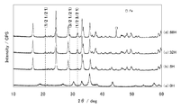
- Example 1 having a baking time of 32 hours has a symmetry of the space group P2 1 / n as compared with Comparative Example 1 having a baking time of 8 hours. It can be seen that peaks derived from the (1/2 1/2 1) plane, (3/2 1/2 1) plane and (1/2 3/2 1) plane of the monoclinic structure appear.
- FIG. 5 (a) is a HAADF-STEM image of the positive electrode active material after firing in Example 1
- FIG. 5 (b) is an EDS map of silicon atoms at the same observation location.
- FIG. 5D is an EDS map of oxygen atoms at the same observation location.
- FIG. 5A approximately spherical particles having a diameter of about 20 to 100 nm can be observed.
- FIGS. 5B to 5D the distribution of atoms of oxygen, iron, and silicon is not significantly different from each other, so that the spatial distribution of elements in the particles is uniform and uniform, and further, between the particles. It can be seen that the composition is uniform and uniform.
- Conductive aid is 10% by weight with respect to the positive electrode active material obtained in Examples and Comparative Examples.
- the mixture was further mixed for 5 hours using a ball mill in which the inside was replaced with nitrogen.
- the mixed powder and polyvinylidene fluoride (PVdF) as a binder were mixed at a weight ratio of 95: 5, and N-methyl-2-pyrrolidone (NMP) was added and kneaded sufficiently to obtain a positive electrode slurry.
- the positive electrode slurry was applied at a coating amount of 50 g / m 2 to an aluminum foil current collector having a surface roughness Rz (JIS B 0601-1994 ten-point average roughness) of 0.7 ⁇ m and a thickness of 15 ⁇ m, and at 120 ° C. Dry for 30 minutes. Thereafter, it was rolled to a density of 2.0 g / cm 3 with a roll press, punched into a 2 cm 2 disk shape, and used as a positive electrode.
- Rz JIS B 0601-1994 ten-point average roughness
- test evaluation of the positive electrode active material of the present invention was performed as follows using the above coin-type lithium secondary battery. Charged to 4.2 V (vs. Li / Li + ) at a test temperature of 25 ° C. and a CC-CV method at a current rate of 0.1 C, and then stopped after the current rate dropped to 0.005 C. . Thereafter, discharging was performed at a rate of 0.1 C to 1.5 V (same as above) by the CC method, and the initial charge / discharge capacity was measured. Furthermore, the charge / discharge capacity was measured up to 50 cycles under the same conditions. In addition, since the measurement was stopped once in 30 cycles, the graph is discontinuous before and after 30 cycles, but the trend of transition of the capacity maintenance rate does not change before and after 30 cycles.
- FIGS. 6 (a) and 6 (b) Graphs of capacity retention ratios with respect to initial discharge capacity of the positive electrode active material according to Example 1 and Comparative Example 1 are shown in FIGS. 6 (a) and 6 (b), respectively, and charge capacity and discharge capacity are shown in Table 1. .
- Example 1 is superior to Comparative Example 1 in both the initial discharge capacity, the 50th cycle discharge capacity, and the 50th cycle capacity retention rate.
- Examples according to the invention are lithium iron silicates having a mixed phase of orthorhombic structure with symmetry of the space group Pmn2 1 and monoclinic structure with symmetry of the space group P2 1 / n
- Comparative Example 1 since the iron crystals were precipitated in the positive electrode active material, the initial discharge capacity and the capacity retention rate were worse than Example 1.
- the cycle characteristics at 50 cycles were evaluated. However, in an actual battery product, about 500 cycles are used, so the difference between the examples and the comparative examples appears more prominently.
- the fine particle mixture is formed by using the spray combustion method.
- the fine particle mixture is fired to generate lithium transition metal silicate.
- iron is used as the transition metal element.
- transition metal elements are added in addition to iron, and other anions other than silicon are added as the anion, the same applies. It is thought that an oblique crystal structure appears.
- the positive electrode obtained by applying the positive electrode active material of the present invention to a predetermined current collector is a rechargeable secondary battery such as a lithium ion secondary battery using a non-aqueous electrolyte. It can be used as a positive electrode exhibiting excellent charge / discharge characteristics. In the future, further improvements will serve as the basis for improving the charge / discharge capacity with the goal of the higher theoretical specific capacity inherent in the compound system of the present invention. Thereby, the characteristic which shows the high energy and the high output which are not in the past can be provided to the secondary battery for industrial use and automobile use which have been put into practical use such as conventional electronic equipment use. Moreover, among the method for producing the fine particle mixture of the present invention, the spray combustion method is particularly excellent in mass productivity and can provide a product at low cost.
Landscapes
- Chemical & Material Sciences (AREA)
- General Chemical & Material Sciences (AREA)
- Chemical Kinetics & Catalysis (AREA)
- Electrochemistry (AREA)
- Inorganic Chemistry (AREA)
- Engineering & Computer Science (AREA)
- Composite Materials (AREA)
- Organic Chemistry (AREA)
- Manufacturing & Machinery (AREA)
- Materials Engineering (AREA)
- Crystallography & Structural Chemistry (AREA)
- Battery Electrode And Active Subsutance (AREA)
- Silicates, Zeolites, And Molecular Sieves (AREA)
Abstract
本発明は、サイクル特性に優れ、充放電を繰り返しても、放電容量の低下が少ないリチウム遷移金属シリケート系正極活物質材料を提供することを目的とする。本発明では、一般式Li2-yFe1-xMxSi1-yXyO4(M=Mn,Ti,Cr,V,Ni,Co,Cu,Zn,Al,Ge,Zr,Mo,Wよりなる群から選ばれる少なくとも1種の遷移金属、X=Ti,Cr,V,Zr,Mo,W,P,Bよりなる群から選ばれる少なくとも1種の元素、0≦x<1、0≦y<0.25)で表され、空間群Pmn21の対称性を有する斜方晶型構造と、空間群P21/nの対称性を有する単斜晶型構造との混合相を有するリチウム遷移金属シリケートを含むことを特徴とする正極活物質材料を提供する。
Description
本発明は、リチウム遷移金属シリケートを含み、非水電解質2次電池の正極に用いられる正極活物質などに関する。
近年、電子機器のモバイル化と高機能化に伴い、駆動電源である2次電池は最重要部品のひとつになっている。特に、Liイオン2次電池は、用いられる正極活物質材料と負極活物質材料の高い電圧から得られるエネルギー密度の高さから、従来のNiCd電池やNi水素電池に替わり、2次電池の主流の位置を占めるに至っている。しかしながら、現在、一般的に用いられる、コバルト酸リチウム(LiCoO2)系正極活物質材料とカーボン系負極活物質材料の組み合わせによるLiイオン2次電池は、昨今の高機能高負荷電子部品の消費電力量を充分に供給することができず、携帯電源としては要求性能を満たすことができなくなっている。
正極活物質材料の理論電気化学比容量は、一般に小さく、コバルト酸系リチウム以外で使用されているマンガン酸系リチウムやニッケル酸系リチウム、または次の実用化を目指し検討されるリン酸鉄系リチウムにしても、現在のカーボン系負極活物質材料の理論比容量よりも小さい値に止まる。しかし、年々性能を少しずつ向上させてきたカーボン系負極活物質材料も理論比容量に近付きつつあり、現用の正極と負極の活物質系統の組み合わせでは、もはや大きな電源容量の向上は見込めなくなってきており、今後の更なる電子機器の高機能化と長時間モバイル駆動化の要求や、採用が拡がる電動工具、無停電電源、蓄電装置などの産業用途、並びに電気自動車用途への搭載には限界が出ている。
このような状況で、現状より飛躍的に電気容量を増加させ得る方法として、カーボン(C)系負極活物質材料にかわる金属系負極活物質材料の適用が検討されている。これは現行のカーボン系負極の数倍から十倍の理論比容量を有する、ゲルマニウム(Ge)やスズ(Sn)、シリコン(Si)系物質を負極活物質材料に用いるものであり、特にSiは、実用化が難しいとされる金属Liに匹敵する比容量を有するので、検討の中心となっている。
しかしながら、組み合わされる他方の正極活物質材料側の比容量が低いために、Siの大きな理論比容量を、実際には実用電池で実現することはできないのが現状である。当面正極活物質材料に実用を検討されている、層状岩塩型またはスピネル型の複合酸化物の単位質量あたりの理論比容量は、せいぜい150mAh/gを超える程度であり、現行のカーボン系負極活物質材料の比容量の2分の1以下であり、Si理論比容量に対しては実に20分の1以下である。このため、正極活物質材料の高容量化を目指した物質系統の検討も必要である。新たな正極活物質材料の候補として、成分によっては従来の2倍の300mAh/gを超えると見込まれている、ケイ酸鉄リチウムなどのリチウム遷移金属シリケート(ケイ酸遷移金属リチウムとも呼ばれる)系化合物の検討が始められている(例えば、特許文献1、非特許文献1を参照)。
安富実希、外4名、「リチウムイオン電池用Li2-xM(SiO4)1-x(PO4)x (M=Fe,Mn)正極活物質の水熱反応による合成とその電気化学特性」、GS Yuasa Technical Report、株式会社ジーエス・ユアサコーポレーション、平成21年6月26日、第6巻、第1号、p21~26
ところが、従来のリチウム遷移金属シリケート系正極活物質材料では、サイクル特性が悪く、充放電を繰り返すうちに放電容量が低下してしまうという問題点があった。
本発明は、前述した問題点に鑑みてなされたもので、その目的とすることは、サイクル特性に優れ、充放電を繰り返しても、放電容量の低下が少ないリチウム遷移金属シリケート系正極活物質材料を提供することを目的とする。
本発明の発明者は、検討の結果、正極活物質材料の前駆体である微粒子混合物を焼成する際に、従来よりも長時間焼成することで、リチウム遷移金属シリケートに、通常生成する空間群Pmn21の対称性を有する斜方晶型構造に加えて、空間群P21/nの対称性を有する単斜晶型構造が出現し、このような正極活物質が優れたサイクル特性を有することを見出し、本発明に至った。
すなわち、本発明は、以下の発明を提供するものである。
(1)一般式Li2-yFe1-xMxSi1-yXyO4(M=Mn,Ti,Cr,V,Ni,Co,Cu,Zn,Al,Ge,Zr,Mo,Wよりなる群から選ばれる少なくとも1種の遷移金属、X=Ti,Cr,V,Zr,Mo,W,P,Bよりなる群から選ばれる少なくとも1種の元素、0≦x<1、0≦y<0.25)で表され、空間群Pmn21の対称性を有する斜方晶型構造と、空間群P21/nの対称性を有する単斜晶型構造との混合相を有するリチウム遷移金属シリケートを含むことを特徴とする正極活物質材料。
(2)CuKα線を用いたX線回折測定において、2θ=24.2度付近の前記斜方晶型構造の(011)面に帰属されるピークの強度I(Pmn21)と、2θ=31.6度付近の前記単斜晶型構造の(1/2 3/2 1)面に帰属されるピークの強度I(P21/n)の強度比I(P21/n)/I(Pmn21)が、0.1以上0.3以下であることを特徴とする(1)に記載の正極活物質材料。
(3)前記単斜晶型構造を有するリチウム遷移金属シリケートが、前記単斜晶型構造を有するリチウム遷移金属シリケートと前記斜方晶型構造を有するリン酸遷移金属シリケートの和に対して、10~30mol%であることを特徴とする(1)に記載の正極活物質材料。
(4)CuKα線を用いたX線回折測定において、2θ=24.2度付近の前記斜方晶型構造の(011)面に帰属されるピークの半値幅値が0.2°以上であることを特徴とする(1)に記載の正極活物質材料。
(5)CuKα線を用いたX線回折測定において、結晶子の大きさが5~50nmの範囲内であることを特徴とする(1)に記載の正極活物質材料。
(6)1次粒子の形状が略球状であり、1次粒子の粒径分布が10nm~200nmの範囲にあることを特徴とする(1)に記載の正極活物質材料。
(7)集電体と、前記集電体の少なくとも片面に、(1)に記載の正極活物質材料を含む正極活物質層と、を有することを特徴とする非水電解質2次電池用正極。
(8)(7)に記載の非水電解質2次電池用正極と、リチウムイオンを吸蔵および放出可能な負極と、前記正極と前記負極との間に配置されたセパレータとを有し、リチウムイオン伝導性を有する電解質中に、前記正極と前記負極と前記セパレータとを設けたことを特徴とする非水電解質2次電池。
(9)リチウム源、遷移金属源およびシリコン源を用いて、微粒子混合物を合成する工程(a)と、前記微粒子混合物に炭素源を混合する工程(b)と、前記炭素源と混合した前記微粒子混合物を、不活性ガス充填雰囲気で、32~50時間の間、650℃~700℃で焼成する工程(c)と、を具備することを特徴とする、リチウム遷移金属シリケートを含む正極活物質材料の製造方法。
(10)前記工程(a)において、前記リチウム源、前記遷移金属源および前記シリコン源を含む混合溶液を、霧状の液滴にて、支燃性ガスと可燃性ガスとともに火炎中に供給して、微粒子混合物を合成することを特徴とする(9)に記載の正極活物質材料の製造方法。
(11)前記工程(a)において、前記火炎の温度が1000~3000℃であることを特徴とする(10)に記載の正極活物質材料の製造方法。
(12)前記工程(a)において、前記可燃性ガスが炭化水素系ガスであり、前記支燃性ガスが空気であることを特徴とする(10)に記載の正極活物質材料の製造方法。
(13)前記工程(a)が、前記リチウム源、前記遷移金属源および前記シリコン源を含む混合溶液の霧状の液滴を加熱して、微粒子混合物を合成する工程であることを特徴とする(9)に記載の正極活物質材料の製造方法。
(14)前記炭素源が、ポリビニルアルコール、ショ糖、カーボンブラックのいずれか一つ以上であることを特徴とする(9)に記載の正極活物質材料の製造方法。
(15)さらに、前記工程(c)の後に、前記リチウム遷移金属シリケート系正極活物質材料を粉砕する工程を具備することを特徴とする(9)に記載の正極活物質材料の製造方法。
(1)一般式Li2-yFe1-xMxSi1-yXyO4(M=Mn,Ti,Cr,V,Ni,Co,Cu,Zn,Al,Ge,Zr,Mo,Wよりなる群から選ばれる少なくとも1種の遷移金属、X=Ti,Cr,V,Zr,Mo,W,P,Bよりなる群から選ばれる少なくとも1種の元素、0≦x<1、0≦y<0.25)で表され、空間群Pmn21の対称性を有する斜方晶型構造と、空間群P21/nの対称性を有する単斜晶型構造との混合相を有するリチウム遷移金属シリケートを含むことを特徴とする正極活物質材料。
(2)CuKα線を用いたX線回折測定において、2θ=24.2度付近の前記斜方晶型構造の(011)面に帰属されるピークの強度I(Pmn21)と、2θ=31.6度付近の前記単斜晶型構造の(1/2 3/2 1)面に帰属されるピークの強度I(P21/n)の強度比I(P21/n)/I(Pmn21)が、0.1以上0.3以下であることを特徴とする(1)に記載の正極活物質材料。
(3)前記単斜晶型構造を有するリチウム遷移金属シリケートが、前記単斜晶型構造を有するリチウム遷移金属シリケートと前記斜方晶型構造を有するリン酸遷移金属シリケートの和に対して、10~30mol%であることを特徴とする(1)に記載の正極活物質材料。
(4)CuKα線を用いたX線回折測定において、2θ=24.2度付近の前記斜方晶型構造の(011)面に帰属されるピークの半値幅値が0.2°以上であることを特徴とする(1)に記載の正極活物質材料。
(5)CuKα線を用いたX線回折測定において、結晶子の大きさが5~50nmの範囲内であることを特徴とする(1)に記載の正極活物質材料。
(6)1次粒子の形状が略球状であり、1次粒子の粒径分布が10nm~200nmの範囲にあることを特徴とする(1)に記載の正極活物質材料。
(7)集電体と、前記集電体の少なくとも片面に、(1)に記載の正極活物質材料を含む正極活物質層と、を有することを特徴とする非水電解質2次電池用正極。
(8)(7)に記載の非水電解質2次電池用正極と、リチウムイオンを吸蔵および放出可能な負極と、前記正極と前記負極との間に配置されたセパレータとを有し、リチウムイオン伝導性を有する電解質中に、前記正極と前記負極と前記セパレータとを設けたことを特徴とする非水電解質2次電池。
(9)リチウム源、遷移金属源およびシリコン源を用いて、微粒子混合物を合成する工程(a)と、前記微粒子混合物に炭素源を混合する工程(b)と、前記炭素源と混合した前記微粒子混合物を、不活性ガス充填雰囲気で、32~50時間の間、650℃~700℃で焼成する工程(c)と、を具備することを特徴とする、リチウム遷移金属シリケートを含む正極活物質材料の製造方法。
(10)前記工程(a)において、前記リチウム源、前記遷移金属源および前記シリコン源を含む混合溶液を、霧状の液滴にて、支燃性ガスと可燃性ガスとともに火炎中に供給して、微粒子混合物を合成することを特徴とする(9)に記載の正極活物質材料の製造方法。
(11)前記工程(a)において、前記火炎の温度が1000~3000℃であることを特徴とする(10)に記載の正極活物質材料の製造方法。
(12)前記工程(a)において、前記可燃性ガスが炭化水素系ガスであり、前記支燃性ガスが空気であることを特徴とする(10)に記載の正極活物質材料の製造方法。
(13)前記工程(a)が、前記リチウム源、前記遷移金属源および前記シリコン源を含む混合溶液の霧状の液滴を加熱して、微粒子混合物を合成する工程であることを特徴とする(9)に記載の正極活物質材料の製造方法。
(14)前記炭素源が、ポリビニルアルコール、ショ糖、カーボンブラックのいずれか一つ以上であることを特徴とする(9)に記載の正極活物質材料の製造方法。
(15)さらに、前記工程(c)の後に、前記リチウム遷移金属シリケート系正極活物質材料を粉砕する工程を具備することを特徴とする(9)に記載の正極活物質材料の製造方法。
本発明により、サイクル特性に優れ、充放電を繰り返しても、放電容量の低下が少ないリチウム遷移金属シリケート系正極活物質材料を提供することができる。
以下に本発明に係る微粒子混合物や正極活物質材料などの好ましい実施態様を説明する。なお、本発明はこれらの実施態様に限定されるものではない。
本発明の正極活物質材料は、粉体材料として得られ、提供される。さらに、正極活物質材料は、そのままの状態、または造粒処理してサイズを大きくした2次粒子にした状態で、分散剤や増粘剤または導電材等を所定割合加えた、水系溶媒または有機溶剤のスラリーとしても提供される。また、集電体基材上にこれらスラリーを塗布して正極活物質材料を皮膜状形成した電極形態としても提供される。そして、本発明における2次電池は、本発明の2次電池用正極を用い、公知の負極やセパレータ、電解液など他の構成材料と共に2次電池として組み立て、提供される。
本発明に係る正極活物質材料は、同一反応系へ構成原料を供給することにより活物質前駆体である微粒子混合物を合成し、これを加熱処理することにより合成される。
(噴霧燃焼法による微粒子混合物の製造方法)
噴霧燃焼法は、塩化物などの原料気体を供給する方法や、気化器を通して原料液体を供給する方法により、構成原料を火炎中へ供給し、構成原料を反応させ、目的物質を得る方法である。噴霧燃焼法として、VAD(Vapor-phase Axial Deposition)法などが好適な例として挙げられる。これらの火炎の温度は、可燃性ガスと支燃性ガスの混合比や、さらに構成原料の添加割合によって変化するが、通常1000~3000℃の間にあり、特に1500~2500℃程度であることが好ましく、さらに1500~2000℃程度であることがより好ましい。火炎温度が低温であると、火炎中での反応が十分に進まずに火炎から外へ出てしまう可能性がある。また、火炎温度が高温であると、生成する微粒子の結晶性が高くなりすぎ、その後の焼成工程において、安定相であるが、正極活物質材料としては好ましくない相が生成する。
噴霧燃焼法は、塩化物などの原料気体を供給する方法や、気化器を通して原料液体を供給する方法により、構成原料を火炎中へ供給し、構成原料を反応させ、目的物質を得る方法である。噴霧燃焼法として、VAD(Vapor-phase Axial Deposition)法などが好適な例として挙げられる。これらの火炎の温度は、可燃性ガスと支燃性ガスの混合比や、さらに構成原料の添加割合によって変化するが、通常1000~3000℃の間にあり、特に1500~2500℃程度であることが好ましく、さらに1500~2000℃程度であることがより好ましい。火炎温度が低温であると、火炎中での反応が十分に進まずに火炎から外へ出てしまう可能性がある。また、火炎温度が高温であると、生成する微粒子の結晶性が高くなりすぎ、その後の焼成工程において、安定相であるが、正極活物質材料としては好ましくない相が生成する。
また、火炎加水分解法は、火炎中で構成原料が加水分解される方法である。火炎加水分解法では、火炎として酸水素火炎が一般に用いられる。水素ガスと酸素ガスが供給された火炎の元に、正極活物質材料の構成原料と、火炎原料(酸素ガスと水素ガス)を同時にノズルから供給して目的物質を合成する。火炎加水分解法では、不活性ガス充填雰囲気中、ナノスケールの極微小な、主として非晶質からなる目的物質の微粒子を得ることができる。
また、熱酸化法とは、火炎中で構成原料が熱酸化される方法である。熱酸化法では、火炎として炭化水素火炎が一般に用いられ、炭化水素ガス(例えばプロパンガス)と酸素ガス供給火炎の元に、構成原料と火炎原料(例えば、プロパンガスと酸素ガス)を同時にノズルから供給しながら目的物質を合成する。
本発明の微粒子混合物を得るための構成原料は、リチウム源、遷移金属源、シリコン源である。例えば、リチウム源としてナフテン酸リチウム、遷移金属源としてのオクチル酸鉄、シリコン源としてオクタメチルシクロテトラシロキサン(OMCTS)などの溶液が用いられる。原料が固体の場合は、粉末のまま供給するか、液体に分散して、または溶媒に溶かして溶液とし、気化器を通じて、火炎に供給する。原料が溶液の場合には、気化器を通じるほかに、供給ノズル前に加熱または減圧およびバブリングによって蒸気圧を高めて気化供給することもできる。
リチウム源としては、塩化リチウム、水酸化リチウム、炭酸リチウム、硝酸リチウム、臭化リチウム、リン酸リチウム、硫酸リチウムなどのリチウム無機酸塩、シュウ酸リチウム、酢酸リチウム、ナフテン酸リチウムなどのリチウム有機酸塩、リチウムエトキシドなどのリチウムアルコキシド、リチウムのβ―ジケトナト化合物などの有機リチウム化合物、酸化リチウム、過酸化リチウム、などを用いることができる。なお、ナフテン酸とは、主に石油中の複数の酸性物質が混合した異なるカルボン酸の混合物で、主成分はシクロペンタンとシクロヘキサンのカルボン酸化合物である。
遷移金属源としては、塩化第二鉄、塩化マンガン、四塩化チタン、塩化バナジウムなどの各種遷移金属の塩化物、シュウ酸鉄、シュウ酸マンガンなど遷移金属のシュウ酸塩、酢酸マンガンなどの遷移金属の酢酸塩、硫酸第一鉄や硫酸マンガンなどの遷移金属の硫酸塩、硝酸マンガンなどの遷移金属の硝酸塩、オキシ水酸化マンガンや水酸化ニッケルなど遷移金属の水酸化物、2-エチルヘキサン酸第二鉄、2-エチルヘキサン酸第二マンガンなどの遷移金属のエチルヘキサン酸塩(オクチル酸塩とも呼ばれる)、テトラ(2-エチルヘキシル)チタネート、ナフテン酸鉄、ナフテン酸マンガン、ナフテン酸クロム、ナフテン酸亜鉛、ナフテン酸ジルコニウム、ナフテン酸コバルトなどのナフテン酸遷移金属塩、ヘキソエートマンガンなどのヘキソエートの遷移金属塩、遷移金属のシクロペンタジエニル化合物、チタンテトライソプロポキシド(TTIP)、チタンアルコキシドなどの遷移金属アルコキシド等を用いることができる。さらに、ステアリン酸、ジメチルジチオカルバミン酸、アセチルアセトネート、オレイン酸、リノール酸、リノレン酸などの遷移金属の有機金属塩、酸化鉄や酸化マンガンほか各種遷移金属の酸化物なども条件により使用される。
後述のように、2種以上の遷移金属をリチウム遷移金属シリケート化合物に用いる場合は、2種以上の遷移金属の原料を火炎中に供給するようにする。
後述のように、2種以上の遷移金属をリチウム遷移金属シリケート化合物に用いる場合は、2種以上の遷移金属の原料を火炎中に供給するようにする。
シリコン源としては、四塩化ケイ素、オクタメチルシクロテトラシロキサン(OMCTS)、二酸化ケイ素や一酸化ケイ素またはこれら酸化ケイ素の水和物、オルトケイ酸やメタケイ酸、メタ二ケイ酸等の縮合ケイ酸、テトラエチルオルトシリケート(テトラエトキシシラン、TEOS)、テトラメチルオルトシリケート(テトラメトキシシラン、TMOS)、メチルトリメトキシシラン(MTMS)、メチルトリエトキシシラン(MTES)、ヘキサメチルジシロキサン(HMDSO)、テトラメチルジシロキサン(TMDSO)、テトラメチルシクロテトラシロキサン(TMCTS)、オクタメチルトリシロキサン(OMTSO)、テトラ-n-ブトキシシラン、等々を用いることができる。
また、リチウム遷移金属シリケート化合物のシリケートの一部を他のアニオンにより置換する場合は、アニオン源として、遷移金属の酸化物、リン酸の原料、ホウ酸の原料を加える
例えば、酸化チタン、亜チタン酸鉄や亜チタン酸マンガンなどの亜チタン酸金属塩、チタン酸亜鉛やチタン酸マグネシウム、チタン酸バリウムなどのチタン酸塩、酸化バナジウム、メタバナジン酸アンモニウム、酸化クロム、クロム酸塩や二クロム酸塩、酸化マンガン、過マンガン酸塩やマンガン酸塩、コバルト酸塩、酸化ジルコニウム、ジルコン酸塩、酸化モリブデン、モリブデン酸塩、酸化タングステン、タングステン酸塩、オルトリン酸やメタリン酸などのリン酸、ピロリン酸、リン酸水素2アンモニウムやリン酸2水素アンモニウムなどのリン酸水素アンモニウム塩、リン酸アンモニウム、リン酸ナトリウムなどの各種リン酸塩またはピロリン酸塩、およびリン酸第一鉄など導入遷移金属のリン酸塩、ホウ酸や三酸化二ホウ素、メタホウ酸ナトリウムや四ホウ酸ナトリウム、ホウ砂などの各種ホウ酸塩を、それぞれ所望のアニオン源と合成条件に応じて用いることができる。
例えば、酸化チタン、亜チタン酸鉄や亜チタン酸マンガンなどの亜チタン酸金属塩、チタン酸亜鉛やチタン酸マグネシウム、チタン酸バリウムなどのチタン酸塩、酸化バナジウム、メタバナジン酸アンモニウム、酸化クロム、クロム酸塩や二クロム酸塩、酸化マンガン、過マンガン酸塩やマンガン酸塩、コバルト酸塩、酸化ジルコニウム、ジルコン酸塩、酸化モリブデン、モリブデン酸塩、酸化タングステン、タングステン酸塩、オルトリン酸やメタリン酸などのリン酸、ピロリン酸、リン酸水素2アンモニウムやリン酸2水素アンモニウムなどのリン酸水素アンモニウム塩、リン酸アンモニウム、リン酸ナトリウムなどの各種リン酸塩またはピロリン酸塩、およびリン酸第一鉄など導入遷移金属のリン酸塩、ホウ酸や三酸化二ホウ素、メタホウ酸ナトリウムや四ホウ酸ナトリウム、ホウ砂などの各種ホウ酸塩を、それぞれ所望のアニオン源と合成条件に応じて用いることができる。
これらの原料を同一反応系に火炎原料と共に供給して微粒子混合物を合成する。生成した微粒子混合物は、排気中からフィルタで回収することができる。また、以下のように芯棒の周囲に生成させることもできる。反応器の中にシリカやシリコン系の芯棒(種棒とも呼ばれる)を設置し、これに吹き付けている酸水素火炎中やプロパン火炎中に火炎原料と共にリチウム源、遷移金属源、シリコン源を供給し、加水分解または酸化反応させると、芯棒表面に主にナノオーダーの微粒子が生成付着する。これらの生成微粒子を回収し、場合によってはフィルタやふるいに掛けて、不純物や凝集粗大分を除く。このようにして得られた微粒子混合物は、ナノスケールの極微小な粒径を持ち、主として非晶質である微粒子からなる。
本発明に係る微粒子混合物の製造方法である噴霧燃焼法では、製造できる微粒子混合物は、非晶質であり、粒子の大きさも小さい。さらに、噴霧燃焼法では、従来の水熱合成法や固相反応法に比べて、短時間で大量の合成が可能であり、低コストで均質な微粒子混合物を得ることができる。
(噴霧燃焼法による微粒子混合物の特徴)
微粒子混合物は、主にリチウム、遷移金属、シリコンの酸化物や、リチウム遷移金属シリケートの非晶質な微粒子からなるが、遷移金属の結晶性酸化物も混合生成している場合が多い。さらに、一部にはリチウム遷移金属シリケート系化合物の結晶成分も含まれる。
微粒子混合物は、主にリチウム、遷移金属、シリコンの酸化物や、リチウム遷移金属シリケートの非晶質な微粒子からなるが、遷移金属の結晶性酸化物も混合生成している場合が多い。さらに、一部にはリチウム遷移金属シリケート系化合物の結晶成分も含まれる。
これら微粒子混合物を2θ=10~60°の範囲の粉末X線回折を測定すると、回折ピークが小さく幅の広い回折角を示す。これらは結晶子の小さい微粒子、または小さな単結晶の集まった多結晶微粒子、並びにこれら微粒子の周囲に非晶質成分が存在する微結晶形態である、それぞれのリチウム遷移金属シリケート系化合物結晶面に由来する回折を示すと思われる。なお、ピークの位置は、結晶のゆがみや測定誤差の影響で、±0.1°~±0.2°程度シフトする可能性がある。
本願の噴霧燃焼法では、火炎中で炭素は燃焼するので、得られた微粒子混合物には、炭素が含まれない。仮に炭素成分が混入したとしても、ごく微量であり、正極に使用する際の導電助剤となるほどの量ではない。
(噴霧熱分解法による微粒子混合物の製造方法)
また、活物質の前駆体である微粒子混合物は、噴霧熱分解法により製造することもできる。噴霧熱分解法とは、リチウム源、遷移金属源、シリコン源を含む混合溶液を、霧状の液滴にし、500~900℃程度まで加熱した反応容器内を流通させ、加熱により熱分解を進行させて微粒子混合物を得る方法である。反応容器での加熱は、電気炉を用いても良いし、火炎炉を用いてもよい。
また、活物質の前駆体である微粒子混合物は、噴霧熱分解法により製造することもできる。噴霧熱分解法とは、リチウム源、遷移金属源、シリコン源を含む混合溶液を、霧状の液滴にし、500~900℃程度まで加熱した反応容器内を流通させ、加熱により熱分解を進行させて微粒子混合物を得る方法である。反応容器での加熱は、電気炉を用いても良いし、火炎炉を用いてもよい。
前述の噴霧燃焼法とは、使用できるリチウム源、遷移金属源、シリコン源の種類や、霧状の液滴を形成する点が同じである。しかし、噴霧燃焼法では、火炎中にて2000℃前後で反応が進むが、噴霧熱分解法では、反応容器内で、より低温で反応が進む点が異なる。また、霧状の液滴のキャリアガスが、噴霧熱分解法では空気や不活性ガスであるのに対して、噴霧燃焼法では可燃性ガスと支燃性ガスを含む点が異なる。また、噴霧熱分解法は、反応容器内を流通させるため、噴霧燃焼法に比べて反応時間が長い点が異なる。
噴霧熱分解法においても、噴霧燃焼法と同様に、活物質の前駆体である、主にリチウム、遷移金属、シリコンの酸化物や、リチウム遷移金属シリケートの非晶質な微粒子からなる微粒子混合物が得られる。
(正極活物質材料の製造)
微粒子混合物を熱処理することにより、微粒子混合物に含まれる非晶質な化合物や酸化物形態の混合物が、熱処理により主にリチウム遷移金属シリケート系の結晶形態の化合物に変化し、リチウム遷移金属シリケート系正極活物質材料が得られる。熱処理を従来に比べて長時間行うことで、従来得られなかった空間群P21/nの対称性を有する単斜晶型構造が出現した。
微粒子混合物を熱処理することにより、微粒子混合物に含まれる非晶質な化合物や酸化物形態の混合物が、熱処理により主にリチウム遷移金属シリケート系の結晶形態の化合物に変化し、リチウム遷移金属シリケート系正極活物質材料が得られる。熱処理を従来に比べて長時間行うことで、従来得られなかった空間群P21/nの対称性を有する単斜晶型構造が出現した。
まず、熱処理後の生成物の導電性を高めるために、微粒子混合物に、ポリビニルアルコールなどの多価アルコールやショ糖などの糖類、カーボンブラックなどの炭素源を添加し、混合する。この際、多価アルコールの一種であるポリビニルアルコールは、炭素源としての役割と同時に、焼成中に鉄成分を還元できるので、特に好ましい。
その後、微粒子混合物と炭素源の混合物を、不活性ガス充填雰囲気で焼成を行う。不活性ガスとしては、窒素ガス、アルゴンガス、ネオンガス、ヘリウムガス、二酸化炭素ガスなどを使用することができる。焼成条件は温度650~750℃で処理時間32時間以上である。この温度範囲と処理時間により、空間群Pmn21の対称性を有する斜方晶型構造と、空間群P21/nの対称性を有する単斜晶型構造との混合相を得ることができる。高温や長時間の熱処理による過大な熱負荷は鉄の結晶を析出させ得るので回避すべきであり、処理時間は50時間以下が好ましい。
その後、焼成後の微粒子混合物を、乳鉢やボールミルほか粉砕手段に掛けることにより、微粒子とすることができ、Liイオンのインターカレーションホスト足り得る本発明の正極活物質材料が得られる。
(本発明にかかる正極活物質材料の特徴)
得られた正極活物質材料に含まれるリチウム遷移金属シリケートは、一般式Li2-yFe1-xMxSi1-yXyO4(M=Mn,Ti,Cr,V,Ni,Co,Cu,Zn,Al,Ge,Zr,Mo,Wよりなる群から選ばれる少なくとも1種の遷移金属、X=Ti,Cr,V,Zr,Mo,W,P,Bよりなる群から選ばれる少なくとも1種の元素、0≦x<1、0≦y<0.25)で表される。ケイ酸鉄リチウムに対して、鉄以外の遷移金属を含むことができ、ケイ酸以外のアニオンを含むことができる。
得られた正極活物質材料に含まれるリチウム遷移金属シリケートは、一般式Li2-yFe1-xMxSi1-yXyO4(M=Mn,Ti,Cr,V,Ni,Co,Cu,Zn,Al,Ge,Zr,Mo,Wよりなる群から選ばれる少なくとも1種の遷移金属、X=Ti,Cr,V,Zr,Mo,W,P,Bよりなる群から選ばれる少なくとも1種の元素、0≦x<1、0≦y<0.25)で表される。ケイ酸鉄リチウムに対して、鉄以外の遷移金属を含むことができ、ケイ酸以外のアニオンを含むことができる。
本発明に係る正極活物質材料は、従来よりも長時間の焼成工程を行うため、図3(a)に示すような空間群Pmn21の対称性を有する斜方晶型構造に加えて、図3(b)に示すような空間群P21/nの対称性を有する単斜晶型構造が出現する。単斜晶型構造が出現した正極活物質材料は、斜方晶型構造のみの従来の正極活物質材料に比べて、優れたサイクル特性を有する。
図3(b)に示すような空間群P21/nの対称性を有する単斜晶型構造は、図3(a)に示すような空間群Pmn21の対称性を有する斜方晶型構造の2倍の体積を持つ超格子構造に当たる。空間群Pmn21のモデルにおけるFeO4やSiO4の四面体が、空間群P21/nのモデルでは、周期的に反転した構造となる。図3(c)に、単斜晶型構造と斜方晶型構造の混合相を有するリチウム遷移金属シリケートのXRDパターンと、各ピークの帰属を示す。また、各ピークの帰属の根拠となる、計算による各構造のX線回折の予想パターンを図3(d)、(e)に示す。
また、空間群P21/nの対称性を有する単斜晶型構造を有するリチウム遷移金属シリケートは、シミュレーションによると、リチウムイオンを結晶から取り出す際のエネルギーが低いことや、結晶構造の安定性が高いことが知られている。
また、空間群P21/nの対称性を有する単斜晶型構造を有するリチウム遷移金属シリケートは、シミュレーションによると、リチウムイオンを結晶から取り出す際のエネルギーが低いことや、結晶構造の安定性が高いことが知られている。
本発明にかかる正極活物質材料は、CuKα線に用いたX線回折測定において、2θ=24.2度付近の斜方晶型構造の(011)面に帰属されるピークの強度I(Pmn21)と、2θ=31.6度付近の単斜晶型構造の(1/2 3/2 1)面に帰属されるピークの強度I(P21/n)の強度比I(P21/n)/I(Pmn21)が、0.1以上0.3以下であることが好ましい。
この強度比が、0.1未満では、斜方晶型構造のみの正極活物質材料と大きな差がなく、サイクル特性向上の効果が少ない。また、強度比が0.3を超えるような正極活物質材料を作ろうとすると、本願の製造方法では、長時間の加熱が必要となり、正極活物質中に鉄が析出してしまうため、好ましくない。
この強度比が、0.1未満では、斜方晶型構造のみの正極活物質材料と大きな差がなく、サイクル特性向上の効果が少ない。また、強度比が0.3を超えるような正極活物質材料を作ろうとすると、本願の製造方法では、長時間の加熱が必要となり、正極活物質中に鉄が析出してしまうため、好ましくない。
また、本発明にかかる正極活物質材料は、単斜晶型構造を有するリチウム遷移金属シリケートが、単斜晶型構造を有するリチウム遷移金属シリケートと前記斜方晶型構造を有するリン酸遷移金属シリケートの和に対して、10~30mol%であることが好ましい。
単斜晶型構造の割合が10mol%未満では、斜方晶型構造のみの正極活物質材料と大きな差がなく、サイクル特性向上の効果が少ない。また、単斜晶型構造の割合が30mol%を超えるような正極活物質材料を作ろうとすると、本願の製造方法では、長時間の加熱が必要となり、正極活物質中に鉄が析出してしまうため、好ましくない。
単斜晶型構造の割合が10mol%未満では、斜方晶型構造のみの正極活物質材料と大きな差がなく、サイクル特性向上の効果が少ない。また、単斜晶型構造の割合が30mol%を超えるような正極活物質材料を作ろうとすると、本願の製造方法では、長時間の加熱が必要となり、正極活物質中に鉄が析出してしまうため、好ましくない。
本発明の正極活物質材料は、2θ=24.2°付近の空間群Pmn21の対称性を有する斜方晶型構造の(011)面に帰属されるピークの半値幅が0.2°以上であることを特徴とする。本発明の正極活物質材料は、非晶質な微粒子からなる微粒子混合物を焼成して得るため、従来の固相反応法や水熱合成法に比べて、結晶性が低くなるためである。なお、半値幅は、通常1°以下であり、多くの場合、0.6°以下である。
また、本発明の正極活物質材料は、シェラーの式から求められる結晶子の大きさが5~50nmの範囲内であることを特徴とする。これは、前述のとおり、本発明の正極活物質材料が、非晶質な微粒子混合物を焼成して得るため、従来の固相反応法や水熱合成法に比べて、結晶子の大きさが小さくなるためである。多くの場合、20~40nmの範囲内である。結晶子が小さいことにより、大電流での充放電時にリチウムが容易に出入りでき、レート特性が向上する。
本発明の正極活物質材料に含まれる結晶化リチウム遷移金属シリケート系化合物の大部分は微細結晶であるが、一部には非晶質成分を含む「微結晶」状態も存在する。例えば、結晶子が複数集まって構成される微粒子が非晶質成分で覆われている状態、或いは非晶質成分マトリクス中に微細な結晶が存在する状態、また微粒子周囲と微粒子間に非晶質成分が存在する状態をいう。
また、本発明に係る正極活物質材料を、透過型電子顕微鏡(TEM)観察により粒径を測定して粒度分布を求めると、10~200nmの範囲に存在し、平均値が25~100nmに存在する。これらの粒子は、結晶子が複数集まって構成される。また、粒度分布は、10~150nmの範囲に存在し、平均値が25~80nmに存在することがより好ましい。なお、粒度分布が10~200nmの範囲に存在するとは、得られた粒度分布が10~200nmの全範囲にわたる必要はなく、得られた粒度分布の下限が10nm以上であり、上限が200nm以下であることを意味する。つまり、得られた粒度分布が10~100nmであってもよいし、50~150nmであってもよい。
本発明に係る正極活物質材料は、粒子の大きさが小さいので、Liイオンまたは電子の、単結晶や多結晶粒子中の導電パスが短く、イオン導電性と電子伝導性が優れるので、充放電反応の障壁を低下させることができる。
本発明に係る正極活物質材料は、粒子の大きさが小さいので、Liイオンまたは電子の、単結晶や多結晶粒子中の導電パスが短く、イオン導電性と電子伝導性が優れるので、充放電反応の障壁を低下させることができる。
本発明に係る正極活物質材料は、略球形を示す。部分的には角ばった箇所も認められるものの、全体としては概略球形状を示す。
本発明にかかる正極活物質において、リチウム遷移金属シリケート微粒子が、少なくとも一部にカーボンコートされるか、少なくとも一部にカーボンが担持されていることが好ましい。カーボンコートとは、粒子の表面を炭素で被覆することであり、カーボン担持とは、粒子内に炭素を含有させることである。カーボンコートやカーボン担持により、材料としての導電率が上昇し、リチウム遷移金属シリケート微粒子への導電パスが得られ、正極に用いる際の電極特性が向上する。
得られた正極活物質材料は、用いる遷移金属とその種類によって、充放電の容量等の特性が変わってくる。例えば、遷移金属源としてFe原料を用いると、結晶構造は安定化し、低コストで合成も容易であるが、Fe1種類だけでは容量は従来レベルに止まる。Mn原料の場合も低コストで合成も容易であるが、リチウムマンガンシリケートはLiのインターカレートとデインターカレートにより結晶構造が崩壊し易い欠点があり、充放電サイクル寿命が短い傾向にある。そこで、FeとMnの2原料を用いたリチウム鉄マンガンシリケート(Li2Fe1-xMnxSiO4)のように遷移金属を2元素用いると、前記の低容量と結晶構造崩壊の問題は解決する。Fe、Mn以外のTi、Cr、V、Ni、Co、Cu、Zn、Al、Ge、Zr、Mo、W、についても同様のことが云える。
他方、アニオンまたはポリアニオンの(SiO4)nシリケートも同様であり、(SiO4)nの一部を他のアニオンにより置換させることもできる。例えば、前記の遷移金属の酸であり、チタン酸(TiO4)やクロム酸(CrO4)、バナジン酸(VO4、V2O7)、ジルコン酸(ZrO4)、モリブデン酸(MoO4、Mo7O24)、タングステン酸(WO4)、等々であり、またはリン酸(PO4)やホウ酸(BO3)による置換である。ポリケイ酸イオンの一部をこれらのアニオン種により置換することにより、Liイオンの脱離と復帰の繰り返しによる結晶構造変化の抑制と安定化に寄与し、サイクル寿命を向上させる。また、これらのアニオン種は、高温においても酸素を放出し難いので、発火につながることもなく安全に用いることができる。
(非水電解質2次電池用正極の製造方法)
微粒子混合物を熱処理して得られた、正極活物質材料を用いて正極電極を形成するには、カーボンをコーティングしたり担持したりした正極活物質材料の粉末に、必要に応じてさらにカーボンブラック(特にアセチレンブラック)などの導電材料を加えると共に、ポリテトラフルオロエチレンやポリフッ化ビニリデン、ポリイミドなどの結着剤、またはブタジエンゴムなどの分散剤、またはカルボキシメチルセルロースほかセルロース誘導体などの増粘剤を加えた混合物を、水系溶媒か有機溶媒マトリクス中に加えてスラリーとしたものを、アルミニウムを95重量%以上含むアルミニウム合金箔などの集電体上に、片面ないしは両面に塗布し、焼成して溶媒を揮発乾固する。これにより、本発明の正極が得られる。
微粒子混合物を熱処理して得られた、正極活物質材料を用いて正極電極を形成するには、カーボンをコーティングしたり担持したりした正極活物質材料の粉末に、必要に応じてさらにカーボンブラック(特にアセチレンブラック)などの導電材料を加えると共に、ポリテトラフルオロエチレンやポリフッ化ビニリデン、ポリイミドなどの結着剤、またはブタジエンゴムなどの分散剤、またはカルボキシメチルセルロースほかセルロース誘導体などの増粘剤を加えた混合物を、水系溶媒か有機溶媒マトリクス中に加えてスラリーとしたものを、アルミニウムを95重量%以上含むアルミニウム合金箔などの集電体上に、片面ないしは両面に塗布し、焼成して溶媒を揮発乾固する。これにより、本発明の正極が得られる。
この際に、スラリーの塗布性や集電体と活物質材料との密着性、集電性を上げるために、前記正極活物質材料とカーボン源等を用いてスプレードライ法により造粒して焼成した2次粒子を、前記の活物質材料に替えてスラリー中に含有させて用いることができる。造粒した2次粒子の塊は概略0.5~20μm程度の大きな塊になるが、これによりスラリー塗布性が飛躍的に向上して、電池電極の特性と寿命もさらに良好となる。スプレードライ法に用いるスラリーは水系溶媒または非水系溶媒のいずれも用いることができる。
さらに、前記正極活物質材料を含むスラリーをアルミニウム合金箔等の集電体上に塗工形成した正極において、活物質層形成面の集電体表面粗さとして日本工業規格(JIS B 0601-1994)に規定される十点平均粗さRzが0.5μm以上であることが望ましい。形成した活物質層と集電体との密着性に優れ、Liイオンの挿入脱離に伴う電子伝導性および集電体までの集電性が増し、充放電のサイクル寿命が向上する。
また、前記の集電体と集電体上形成した活物質層の界面において、集電体の主成分が少なくとも活物質層へ拡散した混成状態を示すと、集電体と活物質材料との界面接合性が向上し、充放電サイクルにおける体積や結晶構造の変化に対して耐性が増すので、サイクル寿命が向上する。前記の集電体表面粗さ条件も満たす場合さらに良好である。溶媒を揮発させ得る充分な焼成条件によれば、集電体成分が活物質層に拡散するなど相互成分を有する界面状態となり密着性に優れ、充放電を重ねてもLiイオンの出入りによる体積変化にも耐え、サイクル寿命が向上する。
(非水電解質2次電池)
本発明の正極を用いた高容量な2次電池を得るには、従来公知の負極活物質材料を用いた負極や電解液、セパレータ、電池ケース等の各種材料を、特に制限なく使用することができる。本発明の非水電解質2次電池は、前述したような正極と負極との間にセパレータを配置して、電池構造体を形成している。このような電池構造体を巻くか、または折って円筒形や角形の電池ケースに入れた後、電解液を注入して、リチウムイオン2次電池が完成する。
本発明の正極を用いた高容量な2次電池を得るには、従来公知の負極活物質材料を用いた負極や電解液、セパレータ、電池ケース等の各種材料を、特に制限なく使用することができる。本発明の非水電解質2次電池は、前述したような正極と負極との間にセパレータを配置して、電池構造体を形成している。このような電池構造体を巻くか、または折って円筒形や角形の電池ケースに入れた後、電解液を注入して、リチウムイオン2次電池が完成する。
具体的には、図2に示したように、本発明の非水電解質2次電池11は、正極13、負極15を、セパレータ17を介して、セパレータ-負極-セパレータ-正極の順に積層配置し、正極13が内側になるように巻回して極板群を構成し、これを電池缶21内に挿入する。そして正極13は正極リード23を介して正極端子27に、負極15は負極リード25を介して電池缶21にそれぞれ接続し、非水電解質2次電池11内部で生じた化学エネルギーを電気エネルギーとして外部に取り出し得るようにする。次いで、電池缶21内に非水系電解質19を充填した後、電池缶21の上端(開口部)に、円形蓋板とその上部の正極端子27からなり、その内部に安全弁機構を内蔵した封口体29を、環状の絶縁ガスケットを介して取り付けて、本発明の非水電解質2次電池11を製造することができる。
本発明に係る正極を用いた2次電池は、容量が高く、良好な電極特性が得られるが、2次電池を構成する非水溶媒を用いる電解液に、フッ素を含有する非水溶媒を用いるか、または添加すると、充放電による繰り返しを経ても容量が低下し難く長寿命となる。例えば、特にはシリコン系の高容量な負極活物質材料を含む負極を用いる場合には、Liイオンのドープ・脱ドープによる大きな膨張収縮を抑制するために、電解液にフッ素を含有するか、フッ素を置換基として有する非水溶媒を含む電解液を用いることが望ましい。フッ素含有溶媒は充電時、特に初めての充電処理の際のLiイオンとの合金化によるシリコン系皮膜の体積膨張を緩和するので、充放電による容量低下を抑制することができる。フッ素含有非水溶媒にはフッ素化エチレンカーボネートやフッ素化鎖状カーボネートなどを用いることができる。フッ素化エチレンカーボネートにはモノ-テトラ-フルオロエチレンカーボネート(4-フルオロ-1,3-ジオキソラン-2-オン、FEC)が、フッ素化鎖状カーボネートにはメチル2,2,2-トリフルオロエチルカーボネート、エチル2,2,2-トリフルオロエチルカーボネートなどがあり、これらを単一または複数併用して電解液に添加して用いることができる。フッ素基はシリコンと結合し易く強固でもあるので、Liイオンとの充電合金化による膨張の際にも皮膜を安定化させ膨張の抑制に寄与することができるとみられる。
(本発明の効果)
本発明に係る正極活物質材料は、空間群Pmn21の対称性を有する斜方晶型構造と、空間群P21/nの対称性を有する単斜晶型構造との混合相を有するリチウム遷移金属シリケートを含むため、サイクル特性に優れ、寿命の長い正極活物質材料が得られる。
本発明に係る正極活物質材料は、空間群Pmn21の対称性を有する斜方晶型構造と、空間群P21/nの対称性を有する単斜晶型構造との混合相を有するリチウム遷移金属シリケートを含むため、サイクル特性に優れ、寿命の長い正極活物質材料が得られる。
本発明の2次電池用正極活物質材料は、従来にないナノスケールの小さな結晶や1次粒子を有しており、さらに結晶性が低いためにLiイオンや電子が移動する距離が小さいために、イオン導電性や電子伝導性が優れるので、本来リチウム遷移金属シリケート系化合物が有する高い容量を充放電に際して得ることができる。
また、本発明に係る正極活物質材料を用いると、活物質材料の粒子自体のLiイオン導電性や電子伝導性が向上する結果、Liイオンのデインターカレートおよびインターカレートが容易になる。本発明は、リチウム遷移金属シリケート系化合物が本来有する高い充放電容量を将来実現する基礎となるものである。
また、本発明に係る正極活物質材料は、従来の材料に比べて、X線回折測定による回折ピーク半値幅が大きく、結晶子の大きさが小さいので、或いは粒子の大きさや、粒度が小さいので、Liイオンまたは電子の、単結晶や多結晶粒子中の導電パスが短く、イオン導電性と電子伝導性が優れる。
さらに、導電助剤や導電性カーボンをコーティングしたり担持したりすると、電気伝導性と導電パス網による集電体までのマクロの集電性が向上し、通常使用の室温などの低温環境でも充放電できるリチウム遷移金属シリケート系化合物を提供することができる。
また、本発明に係る正極活物質材料は、従来の正極活物質材料に比較して、非晶質成分が周囲の一部に存在する結晶を有する微結晶状態であることも特徴である。これらは、従来一般に用いられてきた固相反応法による製造法では得られず、正極活物質材料の材料源となる原料を同一反応系に供給して火炎中で反応させる方法などにより、主に非晶質な活物質前駆体を生成させた後に、焼成を行うことで得られる。このような製造法によれば、焼成後の微粒子混合物をミクロに粉砕することで、粒径が小さく、略球形状微粒子など均質な正極活物質材料を得ることができる。これにより、集電体上に塗工し易い大きさの2次粒子へ造粒することも可能になり、集電体と活物質材料との密着性に優れる、集電体成分が拡散した正極活物質層を得ることができる。
本発明の正極活物質材料に含まれるリチウム遷移金属シリケート系化合物の成分には、充放電反応において2電子反応が得られる複数の遷移金属を含む場合にはさらに高容量を得ることができる。また、酸素を放出しないシリケート系化合物であるので、高温環境においても発火燃焼することがなく、安全な2次電池を提供することが可能になる。
以下に、本発明を実施例により説明するが、本実施例に本発明が何ら限定されることはない。
なお、以下の実施例では、ケイ酸鉄リチウム化合物の合成を行ったが、その他の遷移金属を用いる場合や、その他のアニオンを組成材料に加える場合でも同様に、合成、提供できる。
なお、以下の実施例では、ケイ酸鉄リチウム化合物の合成を行ったが、その他の遷移金属を用いる場合や、その他のアニオンを組成材料に加える場合でも同様に、合成、提供できる。
(1-1)実施例1
(微粒子混合物の作製)
噴霧燃焼法により微粒子混合物を製造する製造装置を図1に示す。図1に示す装置の反応容器は、容器内に微粒子合成ノズル3が配置され、プロパンガス(C3H8)、空気(Air)、及び原料溶液2がノズル3から生じる火炎中に供給される。他方に、生成微粒子や反応生成物を排気する排気管9を有し、排気中の微粒子混合物7を微粒子回収フィルタ5により回収する。ノズルに供給する原料の種類と供給条件は以下とした。また、原料溶液は、液滴の大きさが20μmとなるよう、二流体ノズルを用いて火炎中に供給した。火炎の温度は約2000℃であった。
可燃性ガス:プロパン(C3H8):1dm3/min、
支燃性ガス:空気:5dm3/min、
リチウム源:ナフテン酸リチウム(4M溶液):0.025dm3/min
鉄源:C16H30FeO4(2-エチルヘキサン鉄(II)、オクチル酸鉄)(1M溶液):0.1dm3/min
シリコン源:オクタメチルシクロテトラシロキサン:0.1dm3/min、
(微粒子混合物の作製)
噴霧燃焼法により微粒子混合物を製造する製造装置を図1に示す。図1に示す装置の反応容器は、容器内に微粒子合成ノズル3が配置され、プロパンガス(C3H8)、空気(Air)、及び原料溶液2がノズル3から生じる火炎中に供給される。他方に、生成微粒子や反応生成物を排気する排気管9を有し、排気中の微粒子混合物7を微粒子回収フィルタ5により回収する。ノズルに供給する原料の種類と供給条件は以下とした。また、原料溶液は、液滴の大きさが20μmとなるよう、二流体ノズルを用いて火炎中に供給した。火炎の温度は約2000℃であった。
可燃性ガス:プロパン(C3H8):1dm3/min、
支燃性ガス:空気:5dm3/min、
リチウム源:ナフテン酸リチウム(4M溶液):0.025dm3/min
鉄源:C16H30FeO4(2-エチルヘキサン鉄(II)、オクチル酸鉄)(1M溶液):0.1dm3/min
シリコン源:オクタメチルシクロテトラシロキサン:0.1dm3/min、
噴霧燃焼法による微粒子混合物の製造方法は以下のとおりである。まず、N2ガスを所定量供給し、反応容器中を不活性ガス雰囲気とした。このような条件下で、リチウム源、鉄源、シリコン源をそれぞれ混合した溶液を、霧化器(二流体ノズル)を通じて20μmの液滴にし、プロパンガス及び空気とともに火炎に供給した。火炎中で生成した酸化リチウム、酸化鉄、シリコン酸化物等の微粒子、ケイ酸鉄リチウム化合物の微粒子などの微粒子混合物を微粒子回収フィルタにて回収した。
(正極活物質材料の製造)
次に、微粒子混合物にポリビニルアルコールを、ポリビニルアルコールが全体の10wt%となるように加えて、混合した。
その後、微粒子混合物をN2ガス充填の炉に入れ、650℃で32時間の加熱処理を行って、焼成を行った。焼成と同時にカーボンコートまたはカーボン担持を実施した。この焼成後の微粒子混合物に粉砕処理を行い、正極活物質材料を得た。
次に、微粒子混合物にポリビニルアルコールを、ポリビニルアルコールが全体の10wt%となるように加えて、混合した。
その後、微粒子混合物をN2ガス充填の炉に入れ、650℃で32時間の加熱処理を行って、焼成を行った。焼成と同時にカーボンコートまたはカーボン担持を実施した。この焼成後の微粒子混合物に粉砕処理を行い、正極活物質材料を得た。
(2-1)比較例1
ポリビニルアルコール混合後の焼成条件を、650℃で8時間とした点以外は、実施例1と同様の方法により正極活物質材料を得た。
ポリビニルアルコール混合後の焼成条件を、650℃で8時間とした点以外は、実施例1と同様の方法により正極活物質材料を得た。
(2-2)比較例2
ポリビニルアルコール混合後の焼成条件を、650℃で88時間とした点以外は、実施例1と同様の方法により正極活物質材料を得た。
ポリビニルアルコール混合後の焼成条件を、650℃で88時間とした点以外は、実施例1と同様の方法により正極活物質材料を得た。
(3)試料の測定観察確認
(3-1)粉末X線回折測定
実施例1と比較例1の微粒子混合物及びそれぞれの焼成後の正極活物質材料の粉末X線回折測定(2θ=10~60°)を、CuKα線に線源に用いて行った。X線回折測定結果を図4に示し、解析結果を表1にまとめる。
(3-1)粉末X線回折測定
実施例1と比較例1の微粒子混合物及びそれぞれの焼成後の正極活物質材料の粉末X線回折測定(2θ=10~60°)を、CuKα線に線源に用いて行った。X線回折測定結果を図4に示し、解析結果を表1にまとめる。

図4(a)に示すとおり、活物質の前駆体である焼成前の微粒子混合物は、幅の広いピークを有し、微結晶形態であることがわかる。さらに、図4(b)及び(c)に示すとおり、焼成時間が8時間の比較例1に比べて、焼成時間が32時間の実施例1は、空間群P21/nの対称性を有する単斜晶型構造の(1/2 1/2 1)面と(3/2 1/2 1)面と(1/2 3/2 1)面に由来するピークが現れていることが分かる。
さらに焼成時間を88時間とした比較例2においては、空間群P21/nの対称性を有する単斜晶型構造由来のピークの強度は、実施例1とほとんど変わらないが、45°付近の鉄の結晶由来のピークが強くなり、長時間の焼成により、鉄の結晶が成長したことが分かる。なお、リチウム遷移金属シリケートから、遷移金属の結晶が析出すると、析出した遷移金属が電子を集電体とやり取りする際に、遷移金属の価数変化が起きることや、充放電反応に参加するリチウム遷移金属シリケートが減ることから、充放電容量の低下を引き起こす。比較例2において、焼成時間が88時間で鉄のピークが強くなっていることから、焼成時間は50時間程度まででとどめておくことで、遷移金属の析出を抑えられる。なお、微粒子混合物を焼成することにより、ケイ酸鉄リチウムの結晶構造が成長しているが、焼成後であっても、従来の固相反応法や水熱合成方により製造された材料に比べて、ピークが幅広であり、結晶粒が小さいことがわかる。
(3-2)EDSによる組成分析
実施例1の焼成後の正極活物質材料の粒子形状の観察と組成分析を、走査透過型電子顕微鏡(日本電子製、JEM 3100FEF)を用いて、HAADF-STEM(High-Angle-Annular-Dark-Field-Scanning-Transmission-Electron-Microscopy:高角度散乱暗視野-走査透過型電子顕微鏡法)による粒子形状の観察と、EDS(Energy Dispersive Spectroscopy:エネルギー分散型X線分析)分析により行った。図5(a)は、実施例1の焼成後の正極活物質材料のHAADF-STEM像であり、図5(b)は、同一の観察箇所におけるシリコン原子のEDSマップであり、図5(c)は、同一の観察箇所における鉄原子のEDSマップであり、図5(d)は、同一の観察箇所における酸素原子のEDSマップである。
実施例1の焼成後の正極活物質材料の粒子形状の観察と組成分析を、走査透過型電子顕微鏡(日本電子製、JEM 3100FEF)を用いて、HAADF-STEM(High-Angle-Annular-Dark-Field-Scanning-Transmission-Electron-Microscopy:高角度散乱暗視野-走査透過型電子顕微鏡法)による粒子形状の観察と、EDS(Energy Dispersive Spectroscopy:エネルギー分散型X線分析)分析により行った。図5(a)は、実施例1の焼成後の正極活物質材料のHAADF-STEM像であり、図5(b)は、同一の観察箇所におけるシリコン原子のEDSマップであり、図5(c)は、同一の観察箇所における鉄原子のEDSマップであり、図5(d)は、同一の観察箇所における酸素原子のEDSマップである。
図5(a)において、直径20~100nm程度の略球形の粒子を観察できる。さらに、図5(b)~(d)において、酸素と鉄とシリコンの原子の分布が、それぞれ大きな相違がないことから、粒子内において元素の空間分布に偏りがなく均一であり、さらに粒子間においても組成に偏りがなく均一であることが分かる。
(4)活物質試料を用いた試験評価用正極電極と2次電池の作製
実施例及び比較例で得た正極活物質材料に対して、導電助剤(カーボンブラック)を10重量%となるように混合し、内部を窒素で置換したボールミルを用いて更に5時間混合した。混合粉末と結着剤であるポリフッ化ビニリデン(PVdF)を、重量比95:5の割合で混合し、N-メチル-2-ピロリドン(NMP)を加えて十分混練し、正極スラリーを得た。
実施例及び比較例で得た正極活物質材料に対して、導電助剤(カーボンブラック)を10重量%となるように混合し、内部を窒素で置換したボールミルを用いて更に5時間混合した。混合粉末と結着剤であるポリフッ化ビニリデン(PVdF)を、重量比95:5の割合で混合し、N-メチル-2-ピロリドン(NMP)を加えて十分混練し、正極スラリーを得た。
表面粗さRz(JIS B 0601-1994 十点平均粗さ)が0.7μmの厚さ15μmのアルミニウム箔集電体に、正極スラリーを50g/m2の塗工量で塗布し、120℃で30分間乾燥した。その後、ロールプレスで2.0g/cm3の密度になるように圧延加工し、2cm2の円盤状に打抜いて正極とした。
これらの正極と、負極に金属リチウム、電解液にエチレンカーボネート及びジエチルカーボネートを体積比1:1の割合で混合した混合溶媒にLiPF6を1Mの濃度で溶解したものを用い、リチウム2次電池を作製した。なお、作製雰囲気は露点が-50℃以下とした。各極は集電体の付いた電槽缶に圧着して用いた。上記正極、負極、電解質及びセパレータを用いて直径25mm、厚さ1.6mmのコイン型リチウム2次電池とした。
(5)試料の試験評価
次に、前記のコイン型リチウム2次電池により、本発明の正極活物質材料の試験評価を、次のように実施した。
試験温度25℃、CC-CV法により、0.1Cの電流レートにて、4.2V(対Li/Li+)まで充電を行い、その後電流レートが0.005Cまで低下した後に充電を停止した。その後、0.1Cレートにて、CC法により1.5V(前記に同じ)まで放電を行って、初期の充放電容量を測定した。
さらに、同様の条件にて、50サイクルまで充放電容量を測定した。なお、30サイクルで一旦測定を停止したため、30サイクルの前後でグラフが不連続となっているが、容量維持率の推移の傾向は30サイクルの前後で変化がない。
次に、前記のコイン型リチウム2次電池により、本発明の正極活物質材料の試験評価を、次のように実施した。
試験温度25℃、CC-CV法により、0.1Cの電流レートにて、4.2V(対Li/Li+)まで充電を行い、その後電流レートが0.005Cまで低下した後に充電を停止した。その後、0.1Cレートにて、CC法により1.5V(前記に同じ)まで放電を行って、初期の充放電容量を測定した。
さらに、同様の条件にて、50サイクルまで充放電容量を測定した。なお、30サイクルで一旦測定を停止したため、30サイクルの前後でグラフが不連続となっているが、容量維持率の推移の傾向は30サイクルの前後で変化がない。
実施例1及び比較例1に係る正極活物質材料の初回放電容量に対する容量維持率のグラフを、それぞれ図6(a)、(b)に示し、それぞれの充電容量と放電容量を表1に示す。
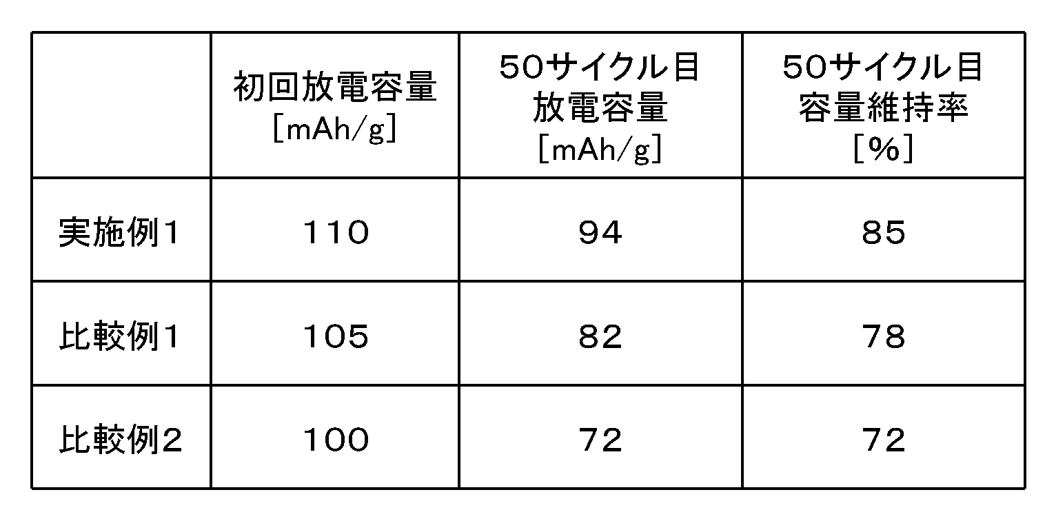
表1に示すとおり、実施例1は、初回放電容量も50サイクル目放電容量も、50サイクル目容量維持率のいずれも比較例1に優れる。本発明により、空間群Pmn21の対称性を有する斜方晶型構造と、空間群P21/nの対称性を有する単斜晶型構造との混合相を有するケイ酸鉄リチウムである実施例1は、斜方晶型構造のみを有するケイ酸鉄リチウムである比較例1よりも初回放電容量もサイクル特性もいずれも優れることが、初めて明らかになった。また、比較例2は、正極活物質材料中に鉄の結晶が析出していたため、初回放電容量と容量維持率が実施例1よりも悪かった。特に、実施例においては50サイクルでのサイクル特性について評価を行ったが、実際の電池製品においては、500サイクル程度は使用するため、実施例と比較例の差はより顕著に現れる。
なお、上述の実施例においては、噴霧燃焼法を用いて微粒子混合物を形成したが、微粒子混合物を焼成する際に、微粒子混合物を焼成してリチウム遷移金属シリケートを生成する点で共通するため、噴霧熱分解法を用いて形成された微粒子混合物を用いても、同様に単斜晶型構造が出現すると考えられる。
また、上述の実施例においては、遷移金属元素として鉄を用いたが、鉄以外に他の遷移金属元素を加えても、また、アニオンとしてシリコン以外に他のアニオンを加えても、同様に単斜晶型構造が出現すると考えられる。
以上に説明したように、本発明の正極活物質材料を、所定の集電体に塗工した正極は、非水電解質を用いるリチウムイオン2次電池をはじめとする充放電可能な2次電池において、優れた充放電特性を示す正極として用いることができる。今後、更なる改良によって、本発明の化合物系統が本来有するさらに高い理論比容量を目標に充放電容量を向上させる基礎となる。これにより、従来の電子機器用途をはじめ、実用化が始まった産業用途や自動車用途の2次電池に、従来にない高エネルギーや高出力を示す特性を付与することができる。しかも、本発明の微粒子混合物の製造法のうち、特に噴霧燃焼法は量産性に優れ、低コストで製品を提供できることが可能になる。
以上、添付図面を参照しながら、本発明の好適な実施形態について説明したが、本発明は係る例に限定されない。当業者であれば、本願で開示した技術的思想の範疇内において、各種の変更例または修正例に想到しえることは明らかであり、それらについても当然に本発明の技術的範囲に属するものと了解される。
1………微粒子製造装置
2………原料溶液
3………微粒子合成ノズル
5………微粒子回収フィルタ
7………微粒子混合物
9………排気管
11………非水電解質2次電池
13………正極
15………負極
17………セパレータ
19………電解質
21………電池缶
23………正極リード
25………負極リード
27………正極端子
29………封口体
2………原料溶液
3………微粒子合成ノズル
5………微粒子回収フィルタ
7………微粒子混合物
9………排気管
11………非水電解質2次電池
13………正極
15………負極
17………セパレータ
19………電解質
21………電池缶
23………正極リード
25………負極リード
27………正極端子
29………封口体
Claims (15)
- 一般式Li2-yFe1-xMxSi1-yXyO4(M=Mn,Ti,Cr,V,Ni,Co,Cu,Zn,Al,Ge,Zr,Mo,Wよりなる群から選ばれる少なくとも1種の遷移金属、X=Ti,Cr,V,Zr,Mo,W,P,Bよりなる群から選ばれる少なくとも1種の元素、0≦x<1、0≦y<0.25)で表され、
空間群Pmn21の対称性を有する斜方晶型構造と、
空間群P21/nの対称性を有する単斜晶型構造との混合相を有するリチウム遷移金属シリケートを含むことを特徴とする正極活物質材料。 - CuKα線を用いたX線回折測定において、2θ=24.2度付近の前記斜方晶型構造の(011)面に帰属されるピークの強度I(Pmn21)と、2θ=31.6度付近の前記単斜晶型構造の(1/2 3/2 1)面に帰属されるピークの強度I(P21/n)の強度比I(P21/n)/I(Pmn21)が、0.1以上0.3以下であることを特徴とする請求項1に記載の正極活物質材料。
- 前記単斜晶型構造を有するリチウム遷移金属シリケートが、前記単斜晶型構造を有するリチウム遷移金属シリケートと前記斜方晶型構造を有するリン酸遷移金属シリケートの和に対して、10~30mol%であることを特徴とする請求項1に記載の正極活物質材料。
- CuKα線を用いたX線回折測定において、2θ=24.2度付近の前記斜方晶型構造の(011)面に帰属されるピークの半値幅値が0.2°以上であることを特徴とする請求項1に記載の正極活物質材料。
- CuKα線を用いたX線回折測定において、結晶子の大きさが5~50nmの範囲内であることを特徴とする請求項1に記載の正極活物質材料。
- 1次粒子の形状が略球状であり、
1次粒子の粒径分布が10nm~200nmの範囲にあることを特徴とする請求項1に記載の正極活物質材料。 - 集電体と、
前記集電体の少なくとも片面に、請求項1に記載の正極活物質材料を含む正極活物質層と、
を有することを特徴とする非水電解質2次電池用正極。 - 請求項7に記載の非水電解質2次電池用正極と、
リチウムイオンを吸蔵および放出可能な負極と、
前記正極と前記負極との間に配置されたセパレータとを有し、
リチウムイオン伝導性を有する電解質中に、前記正極と前記負極と前記セパレータとを設けたことを特徴とする非水電解質2次電池。 - リチウム源、遷移金属源およびシリコン源を用いて、微粒子混合物を合成する工程(a)と、
前記微粒子混合物に炭素源を混合する工程(b)と、
前記炭素源と混合した前記微粒子混合物を、不活性ガス充填雰囲気で、32~50時間の間、650℃~700℃で焼成する工程(c)と、
を具備することを特徴とする、リチウム遷移金属シリケートを含む正極活物質材料の製造方法。 - 前記工程(a)において、
前記リチウム源、前記遷移金属源および前記シリコン源を含む混合溶液を、霧状の液滴にて、支燃性ガスと可燃性ガスとともに火炎中に供給して、微粒子混合物を合成することを特徴とする請求項9に記載の正極活物質材料の製造方法。 - 前記工程(a)において、
前記火炎の温度が1000~3000℃であることを特徴とする請求項10に記載の正極活物質材料の製造方法。 - 前記工程(a)において、
前記可燃性ガスが炭化水素系ガスであり、
前記支燃性ガスが空気であることを特徴とする請求項10に記載の正極活物質材料の製造方法。 - 前記工程(a)が、
前記リチウム源、前記遷移金属源および前記シリコン源を含む混合溶液の霧状の液滴を加熱して、微粒子混合物を合成する工程であることを特徴とする請求項9に記載の正極活物質材料の製造方法。 - 前記炭素源が、ポリビニルアルコール、ショ糖、カーボンブラックのいずれか一つ以上であることを特徴とする請求項9に記載の正極活物質材料の製造方法。
- さらに、前記工程(c)の後に、前記リチウム遷移金属シリケート系正極活物質材料を粉砕する工程を具備することを特徴とする請求項9に記載の正極活物質材料の製造方法。
Priority Applications (3)
| Application Number | Priority Date | Filing Date | Title |
|---|---|---|---|
| CN201280016942.8A CN103493264A (zh) | 2011-04-07 | 2012-04-02 | 正极活性物质材料、非水电解质二次电池及正极活性物质材料的制造方法 |
| JP2012541674A JP5950823B2 (ja) | 2011-04-07 | 2012-04-02 | 正極活物質材料、非水電解質2次電池及び正極活物質材料の製造方法 |
| US14/046,399 US20140038043A1 (en) | 2011-04-07 | 2013-10-04 | Cathode active material, non-aqueous electrolyte secondary battery, and method for producing cathode active material |
Applications Claiming Priority (2)
| Application Number | Priority Date | Filing Date | Title |
|---|---|---|---|
| JP2011085263 | 2011-04-07 | ||
| JP2011-085263 | 2011-04-07 |
Related Child Applications (1)
| Application Number | Title | Priority Date | Filing Date |
|---|---|---|---|
| US14/046,399 Continuation US20140038043A1 (en) | 2011-04-07 | 2013-10-04 | Cathode active material, non-aqueous electrolyte secondary battery, and method for producing cathode active material |
Publications (1)
| Publication Number | Publication Date |
|---|---|
| WO2012137703A1 true WO2012137703A1 (ja) | 2012-10-11 |
Family
ID=46969103
Family Applications (1)
| Application Number | Title | Priority Date | Filing Date |
|---|---|---|---|
| PCT/JP2012/058827 Ceased WO2012137703A1 (ja) | 2011-04-07 | 2012-04-02 | 正極活物質材料、非水電解質2次電池及び正極活物質材料の製造方法 |
Country Status (5)
| Country | Link |
|---|---|
| US (1) | US20140038043A1 (ja) |
| JP (1) | JP5950823B2 (ja) |
| CN (1) | CN103493264A (ja) |
| TW (1) | TWI528621B (ja) |
| WO (1) | WO2012137703A1 (ja) |
Cited By (4)
| Publication number | Priority date | Publication date | Assignee | Title |
|---|---|---|---|---|
| JP2013193927A (ja) * | 2012-03-21 | 2013-09-30 | Furukawa Electric Co Ltd:The | 微粒子混合物の製造方法、微粒子混合物、リチウムイオン二次電池正極活物質、リチウムイオン二次電池および微粒子混合物の製造方法に用いられる水溶液 |
| JP2014120365A (ja) * | 2012-12-18 | 2014-06-30 | Taiheiyo Cement Corp | リチウムイオン電池用正極活物質の製造法 |
| WO2015146423A1 (ja) * | 2014-03-27 | 2015-10-01 | 古河電気工業株式会社 | 正極活物質、二次電池用正極、二次電池、および正極活物質の製造方法 |
| JP2020507889A (ja) * | 2017-05-29 | 2020-03-12 | エルジー・ケム・リミテッド | 二次電池用電極の気孔分布測定方法 |
Families Citing this family (22)
| Publication number | Priority date | Publication date | Assignee | Title |
|---|---|---|---|---|
| US9884765B2 (en) | 2011-06-17 | 2018-02-06 | National Tsing Hua University | Ferrous phosphate powders, lithium iron phosphate powders for li-ion battery, and methods for manufacturing the same |
| US10875771B2 (en) | 2011-06-17 | 2020-12-29 | National Tsing Hua University | Metal (II) phosphate powders, lithium metal phosphate powders for Li-ion battery, and methods for manufacturing the same |
| US10029918B2 (en) | 2011-06-17 | 2018-07-24 | National Tsing Hua University | Ferrous phosphate powders, lithium iron phosphate powders for Li-ion battery, and methods for manufacturing the same |
| US10593947B2 (en) | 2011-06-17 | 2020-03-17 | National Tsing Hua University | Metal (II) phosphate powders, lithium metal phosphate powders for Li-ion battery, and methods for manufacturing the same |
| CN103872325B (zh) * | 2014-04-08 | 2016-03-16 | 国网山东省电力公司聊城供电公司 | 一种镨钴磷掺杂的硅酸锰锂复合正极材料的制备方法 |
| CN105304890A (zh) * | 2014-07-11 | 2016-02-03 | 北京当升材料科技股份有限公司 | 一种含硅锂离子电池正极材料及其制备方法 |
| CN104300116A (zh) * | 2014-10-14 | 2015-01-21 | 上海电力学院 | 一种锂离子电池正极材料及其制备方法 |
| CN105990563B (zh) * | 2015-02-12 | 2019-06-28 | 宁德时代新能源科技股份有限公司 | 二次锂电池及其正极材料、以及正极材料的制备方法 |
| US10707526B2 (en) | 2015-03-27 | 2020-07-07 | New Dominion Enterprises Inc. | All-inorganic solvents for electrolytes |
| JP6477152B2 (ja) | 2015-03-31 | 2019-03-06 | 株式会社デンソー | 正極材料,非水電解質二次電池用正極及び非水電解質二次電池 |
| CN105514380A (zh) * | 2015-12-21 | 2016-04-20 | 宁波高新区锦众信息科技有限公司 | 一种锂离子电池用硅酸亚铁锂复合材料的制备方法 |
| US10707531B1 (en) | 2016-09-27 | 2020-07-07 | New Dominion Enterprises Inc. | All-inorganic solvents for electrolytes |
| CN106602046B (zh) * | 2017-02-23 | 2020-01-17 | 中国科学院宁波材料技术与工程研究所 | 一种锂离子电池硅酸盐正极材料及其制备和应用 |
| CN106910890B (zh) * | 2017-03-03 | 2019-07-12 | 中南大学 | 一种(001)晶面暴露的纳米硅酸盐材料及制备方法 |
| CN108598393B (zh) * | 2018-04-03 | 2020-05-15 | 安徽博石高科新材料股份有限公司 | 一种锂离子电池正极材料及其制备方法 |
| US10714788B2 (en) * | 2018-06-20 | 2020-07-14 | University Of Maryland, College Park | Silicate compounds as solid Li-ion conductors |
| CN110364729B (zh) * | 2019-07-01 | 2022-10-18 | 湖北锂诺新能源科技有限公司 | 钨掺杂硅酸亚铁锂正极材料及其制备方法 |
| CN110993923B (zh) * | 2019-12-26 | 2021-11-23 | 湖北亿纬动力有限公司 | 一种碳包覆辅助的钠钛双掺杂硅酸铁锂正极材料及其制备方法和用途 |
| CN113921818A (zh) * | 2021-08-26 | 2022-01-11 | 恒大新能源技术(深圳)有限公司 | 正极材料及其制备方法和锂离子电池 |
| WO2024000405A1 (zh) * | 2022-06-30 | 2024-01-04 | 宁德新能源科技有限公司 | 正极材料、电化学装置和用电装置 |
| CN115084472B (zh) * | 2022-06-30 | 2023-05-26 | 北京当升材料科技股份有限公司 | 表面包覆正极材料及其制备方法、锂离子电池 |
| CN120376637B (zh) * | 2025-06-26 | 2025-08-15 | 天目湖先进储能技术研究院有限公司 | 一种高倍率的磷酸焦磷酸铁钠-钛酸钡正极材料及其制备方法 |
Citations (6)
| Publication number | Priority date | Publication date | Assignee | Title |
|---|---|---|---|---|
| JP2009170401A (ja) * | 2007-12-19 | 2009-07-30 | Gs Yuasa Corporation | 非水電解質二次電池 |
| WO2010089931A1 (ja) * | 2009-02-04 | 2010-08-12 | 独立行政法人産業技術総合研究所 | リチウムシリケート系化合物の製造方法 |
| WO2010134579A1 (ja) * | 2009-05-22 | 2010-11-25 | シャープ株式会社 | 正極活物質、正極及び非水二次電池 |
| WO2011108464A1 (ja) * | 2010-03-01 | 2011-09-09 | 古河電気工業株式会社 | 正極活物質材料、正極、2次電池及びこれらの製造方法 |
| WO2011108465A1 (ja) * | 2010-03-01 | 2011-09-09 | 古河電気工業株式会社 | 微粒子混合物、活物質凝集体、正極活物質材料、正極、2次電池及びこれらの製造方法 |
| JP2012018836A (ja) * | 2010-07-08 | 2012-01-26 | Sharp Corp | 正極活物質、正極及び非水電解質二次電池 |
Family Cites Families (2)
| Publication number | Priority date | Publication date | Assignee | Title |
|---|---|---|---|---|
| CN100438155C (zh) * | 2006-01-13 | 2008-11-26 | 厦门大学 | 可充锂电池用硅酸锰铁锂/碳复合正极材料及其制备方法 |
| CN101521275B (zh) * | 2009-04-07 | 2011-04-27 | 北京高盟新材料股份有限公司 | 一种二次锂离子电池正极材料硅酸镍锂的制备方法 |
-
2012
- 2012-04-02 JP JP2012541674A patent/JP5950823B2/ja active Active
- 2012-04-02 CN CN201280016942.8A patent/CN103493264A/zh active Pending
- 2012-04-02 WO PCT/JP2012/058827 patent/WO2012137703A1/ja not_active Ceased
- 2012-04-05 TW TW101112029A patent/TWI528621B/zh active
-
2013
- 2013-10-04 US US14/046,399 patent/US20140038043A1/en not_active Abandoned
Patent Citations (6)
| Publication number | Priority date | Publication date | Assignee | Title |
|---|---|---|---|---|
| JP2009170401A (ja) * | 2007-12-19 | 2009-07-30 | Gs Yuasa Corporation | 非水電解質二次電池 |
| WO2010089931A1 (ja) * | 2009-02-04 | 2010-08-12 | 独立行政法人産業技術総合研究所 | リチウムシリケート系化合物の製造方法 |
| WO2010134579A1 (ja) * | 2009-05-22 | 2010-11-25 | シャープ株式会社 | 正極活物質、正極及び非水二次電池 |
| WO2011108464A1 (ja) * | 2010-03-01 | 2011-09-09 | 古河電気工業株式会社 | 正極活物質材料、正極、2次電池及びこれらの製造方法 |
| WO2011108465A1 (ja) * | 2010-03-01 | 2011-09-09 | 古河電気工業株式会社 | 微粒子混合物、活物質凝集体、正極活物質材料、正極、2次電池及びこれらの製造方法 |
| JP2012018836A (ja) * | 2010-07-08 | 2012-01-26 | Sharp Corp | 正極活物質、正極及び非水電解質二次電池 |
Non-Patent Citations (1)
| Title |
|---|
| M. SAIFUL ISLAM: "Recent atomistic modelling studies of energy materials:batteries included", PHILOSOPHICAL TRANSACTIONS OF THE ROYAL SOCIETY A, vol. 368, 2010, pages 3255 - 3267 * |
Cited By (6)
| Publication number | Priority date | Publication date | Assignee | Title |
|---|---|---|---|---|
| JP2013193927A (ja) * | 2012-03-21 | 2013-09-30 | Furukawa Electric Co Ltd:The | 微粒子混合物の製造方法、微粒子混合物、リチウムイオン二次電池正極活物質、リチウムイオン二次電池および微粒子混合物の製造方法に用いられる水溶液 |
| JP2014120365A (ja) * | 2012-12-18 | 2014-06-30 | Taiheiyo Cement Corp | リチウムイオン電池用正極活物質の製造法 |
| WO2015146423A1 (ja) * | 2014-03-27 | 2015-10-01 | 古河電気工業株式会社 | 正極活物質、二次電池用正極、二次電池、および正極活物質の製造方法 |
| JP6046259B2 (ja) * | 2014-03-27 | 2016-12-14 | 古河電気工業株式会社 | 正極活物質、二次電池用正極、二次電池、および正極活物質の製造方法 |
| JP2020507889A (ja) * | 2017-05-29 | 2020-03-12 | エルジー・ケム・リミテッド | 二次電池用電極の気孔分布測定方法 |
| US12196651B2 (en) | 2017-05-29 | 2025-01-14 | Lg Energy Solution, Ltd. | Method for measuring distribution of pores in electrode for secondary battery |
Also Published As
| Publication number | Publication date |
|---|---|
| JPWO2012137703A1 (ja) | 2014-07-28 |
| TWI528621B (zh) | 2016-04-01 |
| US20140038043A1 (en) | 2014-02-06 |
| CN103493264A (zh) | 2014-01-01 |
| JP5950823B2 (ja) | 2016-07-13 |
| TW201242154A (en) | 2012-10-16 |
Similar Documents
| Publication | Publication Date | Title |
|---|---|---|
| JP5950823B2 (ja) | 正極活物質材料、非水電解質2次電池及び正極活物質材料の製造方法 | |
| US9136535B2 (en) | Cathode active material, cathode, secondary battery and manufacturing methods for the same | |
| JP5995726B2 (ja) | 微粒子混合物、正極活物質材料、正極、2次電池及びこれらの製造方法 | |
| JP5566723B2 (ja) | 微粒子混合物、活物質凝集体、正極活物質材料、正極、2次電池及びこれらの製造方法 | |
| CN104781966B (zh) | 正极活性物质及其制造方法、以及非水电解质二次电池用正极、非水电解质二次电池 | |
| JP5718111B2 (ja) | リチウム遷移金属シリケート系正極活物質材料及び非水電解質2次電池用正極の製造方法 | |
| JP5877112B2 (ja) | 正極活物質及びその製造方法並びに負極及び非水電解質2次電池 | |
| JP6046259B2 (ja) | 正極活物質、二次電池用正極、二次電池、および正極活物質の製造方法 | |
| KR101699188B1 (ko) | 정극활물질, 비수전해질 이차전지용 정극, 비수전해질 이차전지 및 정극활물질의 제조방법 | |
| JP2016197539A (ja) | リチウムイオン電池正極活物質およびその製造方法 |
Legal Events
| Date | Code | Title | Description |
|---|---|---|---|
| ENP | Entry into the national phase |
Ref document number: 2012541674 Country of ref document: JP Kind code of ref document: A |
|
| 121 | Ep: the epo has been informed by wipo that ep was designated in this application |
Ref document number: 12767901 Country of ref document: EP Kind code of ref document: A1 |
|
| NENP | Non-entry into the national phase |
Ref country code: DE |
|
| 122 | Ep: pct application non-entry in european phase |
Ref document number: 12767901 Country of ref document: EP Kind code of ref document: A1 |