WO2012133525A1 - 焼成用部材およびこれを用いた焼成用容器ならびに正極材料の製造方法 - Google Patents
焼成用部材およびこれを用いた焼成用容器ならびに正極材料の製造方法 Download PDFInfo
- Publication number
- WO2012133525A1 WO2012133525A1 PCT/JP2012/058121 JP2012058121W WO2012133525A1 WO 2012133525 A1 WO2012133525 A1 WO 2012133525A1 JP 2012058121 W JP2012058121 W JP 2012058121W WO 2012133525 A1 WO2012133525 A1 WO 2012133525A1
- Authority
- WO
- WIPO (PCT)
- Prior art keywords
- firing
- support
- magnesium
- magnesium oxide
- average particle
- Prior art date
- Legal status (The legal status is an assumption and is not a legal conclusion. Google has not performed a legal analysis and makes no representation as to the accuracy of the status listed.)
- Ceased
Links
Images



Classifications
-
- H—ELECTRICITY
- H01—ELECTRIC ELEMENTS
- H01M—PROCESSES OR MEANS, e.g. BATTERIES, FOR THE DIRECT CONVERSION OF CHEMICAL ENERGY INTO ELECTRICAL ENERGY
- H01M4/00—Electrodes
- H01M4/02—Electrodes composed of, or comprising, active material
- H01M4/04—Processes of manufacture in general
- H01M4/0471—Processes of manufacture in general involving thermal treatment, e.g. firing, sintering, backing particulate active material, thermal decomposition, pyrolysis
-
- C—CHEMISTRY; METALLURGY
- C04—CEMENTS; CONCRETE; ARTIFICIAL STONE; CERAMICS; REFRACTORIES
- C04B—LIME, MAGNESIA; SLAG; CEMENTS; COMPOSITIONS THEREOF, e.g. MORTARS, CONCRETE OR LIKE BUILDING MATERIALS; ARTIFICIAL STONE; CERAMICS; REFRACTORIES; TREATMENT OF NATURAL STONE
- C04B35/00—Shaped ceramic products characterised by their composition; Ceramics compositions; Processing powders of inorganic compounds preparatory to the manufacturing of ceramic products
- C04B35/01—Shaped ceramic products characterised by their composition; Ceramics compositions; Processing powders of inorganic compounds preparatory to the manufacturing of ceramic products based on oxide ceramics
- C04B35/03—Shaped ceramic products characterised by their composition; Ceramics compositions; Processing powders of inorganic compounds preparatory to the manufacturing of ceramic products based on oxide ceramics based on magnesium oxide, calcium oxide or oxide mixtures derived from dolomite
- C04B35/04—Shaped ceramic products characterised by their composition; Ceramics compositions; Processing powders of inorganic compounds preparatory to the manufacturing of ceramic products based on oxide ceramics based on magnesium oxide, calcium oxide or oxide mixtures derived from dolomite based on magnesium oxide
- C04B35/053—Fine ceramics
-
- C—CHEMISTRY; METALLURGY
- C04—CEMENTS; CONCRETE; ARTIFICIAL STONE; CERAMICS; REFRACTORIES
- C04B—LIME, MAGNESIA; SLAG; CEMENTS; COMPOSITIONS THEREOF, e.g. MORTARS, CONCRETE OR LIKE BUILDING MATERIALS; ARTIFICIAL STONE; CERAMICS; REFRACTORIES; TREATMENT OF NATURAL STONE
- C04B35/00—Shaped ceramic products characterised by their composition; Ceramics compositions; Processing powders of inorganic compounds preparatory to the manufacturing of ceramic products
- C04B35/01—Shaped ceramic products characterised by their composition; Ceramics compositions; Processing powders of inorganic compounds preparatory to the manufacturing of ceramic products based on oxide ceramics
- C04B35/44—Shaped ceramic products characterised by their composition; Ceramics compositions; Processing powders of inorganic compounds preparatory to the manufacturing of ceramic products based on oxide ceramics based on aluminates
- C04B35/443—Magnesium aluminate spinel
-
- F—MECHANICAL ENGINEERING; LIGHTING; HEATING; WEAPONS; BLASTING
- F27—FURNACES; KILNS; OVENS; RETORTS
- F27D—DETAILS OR ACCESSORIES OF FURNACES, KILNS, OVENS OR RETORTS, IN SO FAR AS THEY ARE OF KINDS OCCURRING IN MORE THAN ONE KIND OF FURNACE
- F27D3/00—Charging; Discharging; Manipulation of charge
- F27D3/12—Travelling or movable supports or containers for the charge
-
- F—MECHANICAL ENGINEERING; LIGHTING; HEATING; WEAPONS; BLASTING
- F27—FURNACES; KILNS; OVENS; RETORTS
- F27D—DETAILS OR ACCESSORIES OF FURNACES, KILNS, OVENS OR RETORTS, IN SO FAR AS THEY ARE OF KINDS OCCURRING IN MORE THAN ONE KIND OF FURNACE
- F27D5/00—Supports, screens or the like for the charge within the furnace
- F27D5/0068—Containers
-
- C—CHEMISTRY; METALLURGY
- C04—CEMENTS; CONCRETE; ARTIFICIAL STONE; CERAMICS; REFRACTORIES
- C04B—LIME, MAGNESIA; SLAG; CEMENTS; COMPOSITIONS THEREOF, e.g. MORTARS, CONCRETE OR LIKE BUILDING MATERIALS; ARTIFICIAL STONE; CERAMICS; REFRACTORIES; TREATMENT OF NATURAL STONE
- C04B2235/00—Aspects relating to ceramic starting mixtures or sintered ceramic products
- C04B2235/02—Composition of constituents of the starting material or of secondary phases of the final product
- C04B2235/30—Constituents and secondary phases not being of a fibrous nature
- C04B2235/32—Metal oxides, mixed metal oxides, or oxide-forming salts thereof, e.g. carbonates, nitrates, (oxy)hydroxides, chlorides
- C04B2235/3205—Alkaline earth oxides or oxide forming salts thereof, e.g. beryllium oxide
- C04B2235/3206—Magnesium oxides or oxide-forming salts thereof
-
- C—CHEMISTRY; METALLURGY
- C04—CEMENTS; CONCRETE; ARTIFICIAL STONE; CERAMICS; REFRACTORIES
- C04B—LIME, MAGNESIA; SLAG; CEMENTS; COMPOSITIONS THEREOF, e.g. MORTARS, CONCRETE OR LIKE BUILDING MATERIALS; ARTIFICIAL STONE; CERAMICS; REFRACTORIES; TREATMENT OF NATURAL STONE
- C04B2235/00—Aspects relating to ceramic starting mixtures or sintered ceramic products
- C04B2235/02—Composition of constituents of the starting material or of secondary phases of the final product
- C04B2235/30—Constituents and secondary phases not being of a fibrous nature
- C04B2235/32—Metal oxides, mixed metal oxides, or oxide-forming salts thereof, e.g. carbonates, nitrates, (oxy)hydroxides, chlorides
- C04B2235/3205—Alkaline earth oxides or oxide forming salts thereof, e.g. beryllium oxide
- C04B2235/3208—Calcium oxide or oxide-forming salts thereof, e.g. lime
-
- C—CHEMISTRY; METALLURGY
- C04—CEMENTS; CONCRETE; ARTIFICIAL STONE; CERAMICS; REFRACTORIES
- C04B—LIME, MAGNESIA; SLAG; CEMENTS; COMPOSITIONS THEREOF, e.g. MORTARS, CONCRETE OR LIKE BUILDING MATERIALS; ARTIFICIAL STONE; CERAMICS; REFRACTORIES; TREATMENT OF NATURAL STONE
- C04B2235/00—Aspects relating to ceramic starting mixtures or sintered ceramic products
- C04B2235/02—Composition of constituents of the starting material or of secondary phases of the final product
- C04B2235/30—Constituents and secondary phases not being of a fibrous nature
- C04B2235/32—Metal oxides, mixed metal oxides, or oxide-forming salts thereof, e.g. carbonates, nitrates, (oxy)hydroxides, chlorides
- C04B2235/3217—Aluminum oxide or oxide forming salts thereof, e.g. bauxite, alpha-alumina
-
- C—CHEMISTRY; METALLURGY
- C04—CEMENTS; CONCRETE; ARTIFICIAL STONE; CERAMICS; REFRACTORIES
- C04B—LIME, MAGNESIA; SLAG; CEMENTS; COMPOSITIONS THEREOF, e.g. MORTARS, CONCRETE OR LIKE BUILDING MATERIALS; ARTIFICIAL STONE; CERAMICS; REFRACTORIES; TREATMENT OF NATURAL STONE
- C04B2235/00—Aspects relating to ceramic starting mixtures or sintered ceramic products
- C04B2235/02—Composition of constituents of the starting material or of secondary phases of the final product
- C04B2235/30—Constituents and secondary phases not being of a fibrous nature
- C04B2235/32—Metal oxides, mixed metal oxides, or oxide-forming salts thereof, e.g. carbonates, nitrates, (oxy)hydroxides, chlorides
- C04B2235/3217—Aluminum oxide or oxide forming salts thereof, e.g. bauxite, alpha-alumina
- C04B2235/3222—Aluminates other than alumino-silicates, e.g. spinel (MgAl2O4)
-
- C—CHEMISTRY; METALLURGY
- C04—CEMENTS; CONCRETE; ARTIFICIAL STONE; CERAMICS; REFRACTORIES
- C04B—LIME, MAGNESIA; SLAG; CEMENTS; COMPOSITIONS THEREOF, e.g. MORTARS, CONCRETE OR LIKE BUILDING MATERIALS; ARTIFICIAL STONE; CERAMICS; REFRACTORIES; TREATMENT OF NATURAL STONE
- C04B2235/00—Aspects relating to ceramic starting mixtures or sintered ceramic products
- C04B2235/02—Composition of constituents of the starting material or of secondary phases of the final product
- C04B2235/30—Constituents and secondary phases not being of a fibrous nature
- C04B2235/32—Metal oxides, mixed metal oxides, or oxide-forming salts thereof, e.g. carbonates, nitrates, (oxy)hydroxides, chlorides
- C04B2235/3231—Refractory metal oxides, their mixed metal oxides, or oxide-forming salts thereof
- C04B2235/3232—Titanium oxides or titanates, e.g. rutile or anatase
-
- C—CHEMISTRY; METALLURGY
- C04—CEMENTS; CONCRETE; ARTIFICIAL STONE; CERAMICS; REFRACTORIES
- C04B—LIME, MAGNESIA; SLAG; CEMENTS; COMPOSITIONS THEREOF, e.g. MORTARS, CONCRETE OR LIKE BUILDING MATERIALS; ARTIFICIAL STONE; CERAMICS; REFRACTORIES; TREATMENT OF NATURAL STONE
- C04B2235/00—Aspects relating to ceramic starting mixtures or sintered ceramic products
- C04B2235/02—Composition of constituents of the starting material or of secondary phases of the final product
- C04B2235/30—Constituents and secondary phases not being of a fibrous nature
- C04B2235/32—Metal oxides, mixed metal oxides, or oxide-forming salts thereof, e.g. carbonates, nitrates, (oxy)hydroxides, chlorides
- C04B2235/3231—Refractory metal oxides, their mixed metal oxides, or oxide-forming salts thereof
- C04B2235/3232—Titanium oxides or titanates, e.g. rutile or anatase
- C04B2235/3234—Titanates, not containing zirconia
- C04B2235/3236—Alkaline earth titanates
-
- C—CHEMISTRY; METALLURGY
- C04—CEMENTS; CONCRETE; ARTIFICIAL STONE; CERAMICS; REFRACTORIES
- C04B—LIME, MAGNESIA; SLAG; CEMENTS; COMPOSITIONS THEREOF, e.g. MORTARS, CONCRETE OR LIKE BUILDING MATERIALS; ARTIFICIAL STONE; CERAMICS; REFRACTORIES; TREATMENT OF NATURAL STONE
- C04B2235/00—Aspects relating to ceramic starting mixtures or sintered ceramic products
- C04B2235/02—Composition of constituents of the starting material or of secondary phases of the final product
- C04B2235/30—Constituents and secondary phases not being of a fibrous nature
- C04B2235/32—Metal oxides, mixed metal oxides, or oxide-forming salts thereof, e.g. carbonates, nitrates, (oxy)hydroxides, chlorides
- C04B2235/3231—Refractory metal oxides, their mixed metal oxides, or oxide-forming salts thereof
- C04B2235/3251—Niobium oxides, niobates, tantalum oxides, tantalates, or oxide-forming salts thereof
-
- C—CHEMISTRY; METALLURGY
- C04—CEMENTS; CONCRETE; ARTIFICIAL STONE; CERAMICS; REFRACTORIES
- C04B—LIME, MAGNESIA; SLAG; CEMENTS; COMPOSITIONS THEREOF, e.g. MORTARS, CONCRETE OR LIKE BUILDING MATERIALS; ARTIFICIAL STONE; CERAMICS; REFRACTORIES; TREATMENT OF NATURAL STONE
- C04B2235/00—Aspects relating to ceramic starting mixtures or sintered ceramic products
- C04B2235/02—Composition of constituents of the starting material or of secondary phases of the final product
- C04B2235/30—Constituents and secondary phases not being of a fibrous nature
- C04B2235/32—Metal oxides, mixed metal oxides, or oxide-forming salts thereof, e.g. carbonates, nitrates, (oxy)hydroxides, chlorides
- C04B2235/3231—Refractory metal oxides, their mixed metal oxides, or oxide-forming salts thereof
- C04B2235/3251—Niobium oxides, niobates, tantalum oxides, tantalates, or oxide-forming salts thereof
- C04B2235/3255—Niobates or tantalates, e.g. silver niobate
-
- C—CHEMISTRY; METALLURGY
- C04—CEMENTS; CONCRETE; ARTIFICIAL STONE; CERAMICS; REFRACTORIES
- C04B—LIME, MAGNESIA; SLAG; CEMENTS; COMPOSITIONS THEREOF, e.g. MORTARS, CONCRETE OR LIKE BUILDING MATERIALS; ARTIFICIAL STONE; CERAMICS; REFRACTORIES; TREATMENT OF NATURAL STONE
- C04B2235/00—Aspects relating to ceramic starting mixtures or sintered ceramic products
- C04B2235/02—Composition of constituents of the starting material or of secondary phases of the final product
- C04B2235/30—Constituents and secondary phases not being of a fibrous nature
- C04B2235/32—Metal oxides, mixed metal oxides, or oxide-forming salts thereof, e.g. carbonates, nitrates, (oxy)hydroxides, chlorides
- C04B2235/3231—Refractory metal oxides, their mixed metal oxides, or oxide-forming salts thereof
- C04B2235/3258—Tungsten oxides, tungstates, or oxide-forming salts thereof
-
- C—CHEMISTRY; METALLURGY
- C04—CEMENTS; CONCRETE; ARTIFICIAL STONE; CERAMICS; REFRACTORIES
- C04B—LIME, MAGNESIA; SLAG; CEMENTS; COMPOSITIONS THEREOF, e.g. MORTARS, CONCRETE OR LIKE BUILDING MATERIALS; ARTIFICIAL STONE; CERAMICS; REFRACTORIES; TREATMENT OF NATURAL STONE
- C04B2235/00—Aspects relating to ceramic starting mixtures or sintered ceramic products
- C04B2235/02—Composition of constituents of the starting material or of secondary phases of the final product
- C04B2235/30—Constituents and secondary phases not being of a fibrous nature
- C04B2235/32—Metal oxides, mixed metal oxides, or oxide-forming salts thereof, e.g. carbonates, nitrates, (oxy)hydroxides, chlorides
- C04B2235/3231—Refractory metal oxides, their mixed metal oxides, or oxide-forming salts thereof
- C04B2235/3258—Tungsten oxides, tungstates, or oxide-forming salts thereof
- C04B2235/326—Tungstates, e.g. scheelite
-
- C—CHEMISTRY; METALLURGY
- C04—CEMENTS; CONCRETE; ARTIFICIAL STONE; CERAMICS; REFRACTORIES
- C04B—LIME, MAGNESIA; SLAG; CEMENTS; COMPOSITIONS THEREOF, e.g. MORTARS, CONCRETE OR LIKE BUILDING MATERIALS; ARTIFICIAL STONE; CERAMICS; REFRACTORIES; TREATMENT OF NATURAL STONE
- C04B2235/00—Aspects relating to ceramic starting mixtures or sintered ceramic products
- C04B2235/02—Composition of constituents of the starting material or of secondary phases of the final product
- C04B2235/50—Constituents or additives of the starting mixture chosen for their shape or used because of their shape or their physical appearance
- C04B2235/54—Particle size related information
- C04B2235/5418—Particle size related information expressed by the size of the particles or aggregates thereof
- C04B2235/5427—Particle size related information expressed by the size of the particles or aggregates thereof millimeter or submillimeter sized, i.e. larger than 0,1 mm
-
- C—CHEMISTRY; METALLURGY
- C04—CEMENTS; CONCRETE; ARTIFICIAL STONE; CERAMICS; REFRACTORIES
- C04B—LIME, MAGNESIA; SLAG; CEMENTS; COMPOSITIONS THEREOF, e.g. MORTARS, CONCRETE OR LIKE BUILDING MATERIALS; ARTIFICIAL STONE; CERAMICS; REFRACTORIES; TREATMENT OF NATURAL STONE
- C04B2235/00—Aspects relating to ceramic starting mixtures or sintered ceramic products
- C04B2235/02—Composition of constituents of the starting material or of secondary phases of the final product
- C04B2235/50—Constituents or additives of the starting mixture chosen for their shape or used because of their shape or their physical appearance
- C04B2235/54—Particle size related information
- C04B2235/5418—Particle size related information expressed by the size of the particles or aggregates thereof
- C04B2235/5436—Particle size related information expressed by the size of the particles or aggregates thereof micrometer sized, i.e. from 1 to 100 micron
-
- C—CHEMISTRY; METALLURGY
- C04—CEMENTS; CONCRETE; ARTIFICIAL STONE; CERAMICS; REFRACTORIES
- C04B—LIME, MAGNESIA; SLAG; CEMENTS; COMPOSITIONS THEREOF, e.g. MORTARS, CONCRETE OR LIKE BUILDING MATERIALS; ARTIFICIAL STONE; CERAMICS; REFRACTORIES; TREATMENT OF NATURAL STONE
- C04B2235/00—Aspects relating to ceramic starting mixtures or sintered ceramic products
- C04B2235/60—Aspects relating to the preparation, properties or mechanical treatment of green bodies or pre-forms
- C04B2235/602—Making the green bodies or pre-forms by moulding
- C04B2235/6021—Extrusion moulding
-
- C—CHEMISTRY; METALLURGY
- C04—CEMENTS; CONCRETE; ARTIFICIAL STONE; CERAMICS; REFRACTORIES
- C04B—LIME, MAGNESIA; SLAG; CEMENTS; COMPOSITIONS THEREOF, e.g. MORTARS, CONCRETE OR LIKE BUILDING MATERIALS; ARTIFICIAL STONE; CERAMICS; REFRACTORIES; TREATMENT OF NATURAL STONE
- C04B2235/00—Aspects relating to ceramic starting mixtures or sintered ceramic products
- C04B2235/70—Aspects relating to sintered or melt-casted ceramic products
- C04B2235/74—Physical characteristics
- C04B2235/77—Density
-
- C—CHEMISTRY; METALLURGY
- C04—CEMENTS; CONCRETE; ARTIFICIAL STONE; CERAMICS; REFRACTORIES
- C04B—LIME, MAGNESIA; SLAG; CEMENTS; COMPOSITIONS THEREOF, e.g. MORTARS, CONCRETE OR LIKE BUILDING MATERIALS; ARTIFICIAL STONE; CERAMICS; REFRACTORIES; TREATMENT OF NATURAL STONE
- C04B2235/00—Aspects relating to ceramic starting mixtures or sintered ceramic products
- C04B2235/70—Aspects relating to sintered or melt-casted ceramic products
- C04B2235/74—Physical characteristics
- C04B2235/78—Grain sizes and shapes, product microstructures, e.g. acicular grains, equiaxed grains, platelet-structures
- C04B2235/786—Micrometer sized grains, i.e. from 1 to 100 micron
-
- C—CHEMISTRY; METALLURGY
- C04—CEMENTS; CONCRETE; ARTIFICIAL STONE; CERAMICS; REFRACTORIES
- C04B—LIME, MAGNESIA; SLAG; CEMENTS; COMPOSITIONS THEREOF, e.g. MORTARS, CONCRETE OR LIKE BUILDING MATERIALS; ARTIFICIAL STONE; CERAMICS; REFRACTORIES; TREATMENT OF NATURAL STONE
- C04B2235/00—Aspects relating to ceramic starting mixtures or sintered ceramic products
- C04B2235/70—Aspects relating to sintered or melt-casted ceramic products
- C04B2235/80—Phases present in the sintered or melt-cast ceramic products other than the main phase
-
- C—CHEMISTRY; METALLURGY
- C04—CEMENTS; CONCRETE; ARTIFICIAL STONE; CERAMICS; REFRACTORIES
- C04B—LIME, MAGNESIA; SLAG; CEMENTS; COMPOSITIONS THEREOF, e.g. MORTARS, CONCRETE OR LIKE BUILDING MATERIALS; ARTIFICIAL STONE; CERAMICS; REFRACTORIES; TREATMENT OF NATURAL STONE
- C04B2235/00—Aspects relating to ceramic starting mixtures or sintered ceramic products
- C04B2235/70—Aspects relating to sintered or melt-casted ceramic products
- C04B2235/96—Properties of ceramic products, e.g. mechanical properties such as strength, toughness, wear resistance
-
- C—CHEMISTRY; METALLURGY
- C04—CEMENTS; CONCRETE; ARTIFICIAL STONE; CERAMICS; REFRACTORIES
- C04B—LIME, MAGNESIA; SLAG; CEMENTS; COMPOSITIONS THEREOF, e.g. MORTARS, CONCRETE OR LIKE BUILDING MATERIALS; ARTIFICIAL STONE; CERAMICS; REFRACTORIES; TREATMENT OF NATURAL STONE
- C04B2235/00—Aspects relating to ceramic starting mixtures or sintered ceramic products
- C04B2235/70—Aspects relating to sintered or melt-casted ceramic products
- C04B2235/96—Properties of ceramic products, e.g. mechanical properties such as strength, toughness, wear resistance
- C04B2235/9669—Resistance against chemicals, e.g. against molten glass or molten salts
- C04B2235/9692—Acid, alkali or halogen resistance
-
- H—ELECTRICITY
- H01—ELECTRIC ELEMENTS
- H01M—PROCESSES OR MEANS, e.g. BATTERIES, FOR THE DIRECT CONVERSION OF CHEMICAL ENERGY INTO ELECTRICAL ENERGY
- H01M4/00—Electrodes
- H01M4/02—Electrodes composed of, or comprising, active material
- H01M4/36—Selection of substances as active materials, active masses, active liquids
- H01M4/48—Selection of substances as active materials, active masses, active liquids of inorganic oxides or hydroxides
- H01M4/485—Selection of substances as active materials, active masses, active liquids of inorganic oxides or hydroxides of mixed oxides or hydroxides for inserting or intercalating light metals, e.g. LiTi2O4 or LiTi2OxFy
-
- H—ELECTRICITY
- H01—ELECTRIC ELEMENTS
- H01M—PROCESSES OR MEANS, e.g. BATTERIES, FOR THE DIRECT CONVERSION OF CHEMICAL ENERGY INTO ELECTRICAL ENERGY
- H01M4/00—Electrodes
- H01M4/02—Electrodes composed of, or comprising, active material
- H01M4/36—Selection of substances as active materials, active masses, active liquids
- H01M4/48—Selection of substances as active materials, active masses, active liquids of inorganic oxides or hydroxides
- H01M4/50—Selection of substances as active materials, active masses, active liquids of inorganic oxides or hydroxides of manganese
- H01M4/505—Selection of substances as active materials, active masses, active liquids of inorganic oxides or hydroxides of manganese of mixed oxides or hydroxides containing manganese for inserting or intercalating light metals, e.g. LiMn2O4 or LiMn2OxFy
-
- H—ELECTRICITY
- H01—ELECTRIC ELEMENTS
- H01M—PROCESSES OR MEANS, e.g. BATTERIES, FOR THE DIRECT CONVERSION OF CHEMICAL ENERGY INTO ELECTRICAL ENERGY
- H01M4/00—Electrodes
- H01M4/02—Electrodes composed of, or comprising, active material
- H01M4/36—Selection of substances as active materials, active masses, active liquids
- H01M4/48—Selection of substances as active materials, active masses, active liquids of inorganic oxides or hydroxides
- H01M4/52—Selection of substances as active materials, active masses, active liquids of inorganic oxides or hydroxides of nickel, cobalt or iron
- H01M4/525—Selection of substances as active materials, active masses, active liquids of inorganic oxides or hydroxides of nickel, cobalt or iron of mixed oxides or hydroxides containing iron, cobalt or nickel for inserting or intercalating light metals, e.g. LiNiO2, LiCoO2 or LiCoOxFy
-
- Y—GENERAL TAGGING OF NEW TECHNOLOGICAL DEVELOPMENTS; GENERAL TAGGING OF CROSS-SECTIONAL TECHNOLOGIES SPANNING OVER SEVERAL SECTIONS OF THE IPC; TECHNICAL SUBJECTS COVERED BY FORMER USPC CROSS-REFERENCE ART COLLECTIONS [XRACs] AND DIGESTS
- Y02—TECHNOLOGIES OR APPLICATIONS FOR MITIGATION OR ADAPTATION AGAINST CLIMATE CHANGE
- Y02E—REDUCTION OF GREENHOUSE GAS [GHG] EMISSIONS, RELATED TO ENERGY GENERATION, TRANSMISSION OR DISTRIBUTION
- Y02E60/00—Enabling technologies; Technologies with a potential or indirect contribution to GHG emissions mitigation
- Y02E60/10—Energy storage using batteries
Definitions
- the present invention mainly relates to a firing member used for producing a positive electrode material of a lithium ion secondary battery, a firing container using the same, and a method for producing the positive electrode material.
- a porous firing container made of mullite-cordierite excellent in thermal shock resistance is a raw material powder (eg, lithium compound) of a positive electrode material (eg, LiMnO 2 , LiCoO 2 , LiNiO 2 ) of a lithium ion secondary battery. , Transition metal compounds).
- a raw material powder eg, lithium compound
- a positive electrode material eg, LiMnO 2 , LiCoO 2 , LiNiO 2
- Transition metal compounds eg, Transition metal compounds
- the porous firing container made of mullite-cordierite is eroded by components (alkaline components such as lithium) constituting the positive electrode material of the lithium ion secondary battery in the firing step of the raw material powder. .
- the firing container deteriorates in a short period of time, so the firing container had to be replaced frequently.
- Patent Document 1 proposes a firing container for positive electrode active material powder having a dense ceramic coating layer having a silicon content of less than 5% on the inner surface of the container substrate. Has been.
- the present invention provides a firing member excellent in heat resistance, corrosion resistance and thermal shock resistance to a positive electrode material of a lithium ion secondary battery, a firing container using the same, and a method for firing the positive electrode material. Is.
- the firing member of the present invention is characterized in that it is composed of a composite ceramic containing magnesium oxide as a main component and magnesium metalate as a subcomponent.
- the firing container of the present invention is characterized by comprising a support made of the above-mentioned firing member and a frame provided with a cavity for accommodating the support.
- the method for producing a positive electrode material of the present invention includes a step of placing raw material powder containing an alkali component on the support of the firing container and firing it.
- magnesium oxide is excellent in heat resistance and corrosion resistance against an alkali component because it is composed of a composite ceramic containing magnesium oxide as a main component and magnesium metalate as an accessory component, Since magnesium metalate is excellent in thermal shock resistance, it can be excellent in heat resistance, corrosion resistance to components constituting the positive electrode material of the lithium ion secondary battery, and thermal shock resistance.
- the firing container has a long length because it comprises the support made of the firing member of the present invention and the frame provided with the cavity portion for accommodating the support. In addition to extending the service life, when the deterioration of the support progresses, only the support needs to be replaced, and the running cost can be reduced.
- the positive electrode material can be obtained efficiently. it can.
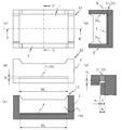
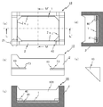
- firing container of the present embodiment are shown, (a) and (b) are a plan view and a front view, respectively, (c) and (d) are DD ′ line, E ⁇ It is sectional drawing in the E 'line, (e) is an expanded sectional view of the T section shown by (d).
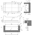
- Another example of the firing container of the present embodiment is shown in (a) and (b), which are a plan view and a front view, respectively, and (c) and (d) are respectively a FF ′ line and a G- It is sectional drawing in a G 'line, (e) is an expanded sectional view of the U part shown by (d).
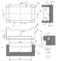
- firing container of the present embodiment are shown, (a) and (b) are a plan view and a front view, respectively, (c) and (d) are respectively a line HH ′, I— It is sectional drawing in the I 'line.
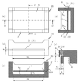
- Another example of the firing container of the present embodiment is shown in (a) and (b), respectively, a plan view and a front view, and (c) and (d) are respectively a JJ ′ line and a K- It is sectional drawing in a K 'line, (e) is a top view of a stationary member.
- firing container of the present embodiment is shown in (a) and (b), which are a plan view and a front view, respectively, and (c) and (d) are respectively an LL ′ line and an M ⁇ It is sectional drawing in a M 'line.
- FIG. 1 is a cross-sectional view showing an example of a firing container of the present embodiment.
- a firing container 10 shown in FIG. 1 includes a support 1 made of the firing member of the present embodiment, and a frame 2 provided with a cavity portion 101 that accommodates the support 1.
- the support body 1 shown in FIG. 1 is the member for baking in this embodiment.
- the support 1 shown in FIG. 1 has a square plate shape, and the four corners of the lower surface are fixed to the inner bottom surface of the frame body 2 (hereinafter sometimes simply referred to as the bottom surface) by the adhesive 3.
- the support body 1 can be easily detached from the frame body 2 by applying a slight impact to the support body 1.
- the support body 1 can be easily attached to the frame body 2 so that attachment or detachment is possible.
- the support 1 may be disk-shaped, and the adhesive 3 may be applied to the disk at predetermined intervals and fixed to the bottom surface of the frame 2.
- the firing member of the present embodiment is made of a composite ceramic containing magnesium oxide as a main component and magnesium metalate as a subcomponent.
- Magnesium oxide has excellent heat resistance and corrosion resistance to alkali components
- magnesium metalate has excellent corrosion resistance to alkali components and excellent thermal shock resistance. Therefore, the firing member of the present embodiment is for firing excellent in corrosion resistance and thermal shock resistance to a material to be fired containing an alkaline component such as lithium, for example, a raw material powder of a positive electrode material for a lithium ion secondary battery. It can be a member.
- magnesium metalate include magnesium aluminate, magnesium titanate, magnesium tantalate, and magnesium tungstate.
- the firing member of the present embodiment contains more than 50% by mass of the main component magnesium oxide, and particularly when it contains 60% by mass or more, the heat resistance and the corrosion resistance to the alkali component increase. Is preferred.
- the main component and subcomponent in this embodiment mean the component with the largest content after the component with the largest content and the component with the largest content among the components contained in the firing member.
- the composition of the component contained in the firing member can be identified using an X-ray diffraction method.
- the amount of each element contained in the firing member can be determined by X-ray fluorescence analysis or ICP (Inductively-Coupled-Plasma) emission spectroscopy.
- ICP Inductively-Coupled-Plasma emission spectroscopy.
- the content of magnesium oxide, which is the main component is obtained by calculating the total content of magnesium in the firing member, converting to magnesium oxide, and subtracting the component amount of magnesium oxide constituting the metal acid magnesium as the main component. It is the content of certain magnesium oxide.
- the component amount of the magnesium oxide constituting the metal acid magnesium can be calculated as described below.
- the content of a metal other than magnesium (excluding inevitable impurities) is obtained, and the value converted from this content into an oxide is regarded as the component amount of a metal oxide other than magnesium constituting the metal acid magnesium.
- the ratio of the oxide component of the metal other than magnesium and the magnesium oxide component may be determined to calculate the component amount of magnesium oxide that constitutes the metal acid magnesium.
- the content of magnesium metalate which is a subcomponent, may be the sum of the component amounts of metal oxides and magnesium oxide other than magnesium constituting the magnesium metalate.
- composition formula of magnesium aluminate is expressed as MgAl 2 O 4
- the molar ratio of MgO and Al 2 O 3 is preferably a constant ratio of 1: 1, but MgO and Al 2 O 3 and The molar ratio is, for example, within the range of 1: 0.8 to 1: 1.2.
- composition formula of magnesium titanate is expressed as MgTiO 3 , and the molar ratio of MgO and TiO 2 is preferably a constant ratio of 1: 1, but the molar ratio of MgO and TiO 2 is, for example, Any value in the range of 1: 0.8 to 1: 1.2 is acceptable.
- composition formula of magnesium tantalate is expressed as Mg 4 Ta 2 O 9 and the molar ratio of MgO to Ta 2 O 5 is preferably a constant ratio of 4: 1, but MgO and Ti 2 O
- the molar ratio with 5 is in the range of 4: 0.8 to 4: 1.2.
- the magnesium tungstate is represented by the composition formula MgWO 3 , and the molar ratio of MgO and WO 3 is preferably a constant ratio of 1: 1, but the molar ratio of MgO and WO 3 is, for example, Any value in the range of 1: 0.8 to 1: 1.2 is acceptable.
- the subcomponent of the firing member of the present embodiment is preferably magnesium aluminate among the above from the viewpoint of cost reduction of the firing member.
- the average particle diameter of the magnesium oxide crystal particles on the surface is larger than the average particle diameter of the magnesium aluminate crystal particles.
- the area of the magnesium oxide crystal particles on the surface of the firing member can be increased. Therefore, even if it comes into contact with an alkali component at a high temperature, it is difficult to be eroded.
- the average particle diameter of the magnesium oxide crystal particles on the surface is more preferably 7 ⁇ m or more than the average particle diameter of the magnesium aluminate crystal particles.
- the average particle diameter of the magnesium oxide crystal particles is preferably 45 ⁇ m or less.
- the average particle diameter of the magnesium oxide crystal particles is 45 ⁇ m or less, the magnesium oxide crystal particles that have grown abnormally are restricted, so that a member for firing with high spalling resistance can be obtained.
- the spalling resistance in the present embodiment refers to a characteristic in which when a firing member is subjected to a thermal shock, a crack or a crack is generated and the portion is not easily peeled off.
- the average particle diameter of the magnesium oxide crystal particles is 15 ⁇ m or more, the magnesium oxide crystal particles having high corrosion resistance to the alkali component are large, and thus the corrosion resistance tends to be increased. Therefore, the average particle size of the magnesium oxide crystal particles is preferably 15 ⁇ m or more and 45 ⁇ m or less.
- the average particle diameter of the magnesium aluminate crystal particles is 5 ⁇ m or more and 10 ⁇ m or less.
- the corrosion resistance can be further increased, and the thermal shock resistance hardly deteriorates even when exposed to a strong alkaline gas. It can be set as the member for baking.
- the average particle diameter of the magnesium oxide crystal particles is 1.5 to 9 times the crystal particle diameter of magnesium aluminate.
- the average particle diameter of each crystal particle of magnesium oxide and magnesium aluminate on the surface of the firing member can be determined by the following procedure.
- a part of the firing member including the surface is embedded in a cold embedding resin such as a polyester resin so that the surface becomes an observation surface, and a cylindrical sample is manufactured. Polishing using Ecomet 3, Buehler (made), to obtain the observation surface. Then, using a scanning electron microscope, the reflected electron composition image obtained by photographing the observation surface of the firing member at a magnification of, for example, 300 times, and the observation surface is irradiated with an electron beam using an X-ray microanalyzer.
- the components of the crystal particles constituting the observation surface can be specified.
- the crystal particles in which the presence of magnesium is recognized more than other components are magnesium oxide crystal particles, and aluminum and magnesium
- the crystal particles in which the presence of selenium is observed more than the other components are magnesium aluminate crystal particles.
- the average particle diameter of each crystal particle of magnesium oxide and magnesium aluminate is equivalent to a circle with 30 samples each using, for example, image analysis software “IMAGE-PRO PLUS” (registered trademark, MEDIA CYBERNETICS). The diameter may be calculated and the average value may be obtained.
- the average particle diameter of the magnesium oxide crystal particles when the mechanical strength is increased, can be 10 ⁇ m or less.
- the average particle diameter of the magnesium oxide crystal particles is 10 ⁇ m or less, a denser firing member can be obtained, and therefore the mechanical strength can be increased. Therefore, when the average particle diameter of the magnesium oxide crystal particles is 10 ⁇ m or less, a firing member having high processability and mechanical strength can be obtained.
- the firing member of the present embodiment has a porosity of 30% by volume or less (excluding 0).
- the porosity is 30% by volume or less, the mechanical strength tends to be increased.
- the porosity is preferably 15% by volume or more and 30% by volume or less in order to effectively suppress the progress of cracks.
- the porosity of the member for baking can be calculated
- the firing member of the present embodiment preferably has an average pore diameter of 3 ⁇ m or less.
- the average pore diameter is 3 ⁇ m or less, the mechanical strength tends to be increased.
- the average pore diameter is preferably 1 ⁇ m or more and 3 ⁇ m or less.
- the average pore diameter may be determined according to the mercury intrusion method. Specifically, first, a sample is cut out from the firing member so that the mass is 2 g or more and 3 g or less. Next, using a mercury intrusion porosimeter, mercury is injected into the pores of the sample, and the pressure applied to the mercury and the volume of mercury that has entered the pores are measured.
- the volume of mercury is equal to the volume of pores, and the following formula (1) (Washburn's relational expression) is established for the pressure applied to mercury and the pore diameter.
- d -4 ⁇ cos ⁇ / P (1)
- d pore diameter (m)
- P Pressure applied to mercury
- ⁇ Surface tension of mercury (0.485N / m)
- ⁇ Contact angle between mercury and pore surface (130 °)
- Each pore diameter d with respect to each pressure P is obtained from the equation (1), and the distribution of each pore diameter d and the cumulative pore volume can be derived.
- the pore diameter (D 50 ) corresponding to 50% by volume of the cumulative pore volume may be used as the average pore diameter.
- the firing member of the present embodiment may further include at least one of lithium, cobalt, manganese, nickel, and phosphorus.
- at least one of lithium, cobalt, manganese, nickel, and phosphorus When any one of these components is included, when the cathode material for a lithium ion secondary battery is fired, if the temperature is raised, an oxide film containing the above components is formed on the surface of the firing member. The diffusion rate becomes slow, and deterioration can be suppressed.
- each content of lithium, cobalt, manganese, nickel, and phosphorus is 3% by mass or more and 5% by mass or less.
- FIG. 2 is a cross-sectional view showing another example of the firing container of the present embodiment
- FIG. 3 is a plan view showing still another example of the firing container of the present embodiment
- b) is a cross-sectional view taken along line AA ′.
- the support body 1 shown in FIG. 2 is fixed to the bottom surface of the frame body 2 by bolts 5 inserted into the through holes 4 of the frame body 2 and nuts 6 for screwing the bolts 5, and by loosening the nuts 6,
- the support 1 can be easily detached from the frame 2. Thereby, the support body 1 can be easily attached to the frame body 2 so that attachment or detachment is possible.
- the support 1 shown in FIG. 3 is fixed so as to be sandwiched between the frame 2 and the pin 7 by a pin 7 inserted into the through hole 4 of the frame 2 and bonded to the through hole 4 with an adhesive.
- the support 1 can be removed from the frame 2 by applying a slight impact to the pin 7 and removing the pin 7. Thereby, the support body 1 can be easily attached to the frame body 2 so that attachment or detachment is possible.
- the firing containers 10 to 12 shown in FIGS. 1 to 3 can extend the life of the firing containers 10 to 12 because the support 1 made of a firing member and the support 1 are detachably attached. In addition, when the deterioration of the support 1 progresses, only the support 1 needs to be replaced, and the running cost can be reduced.
- FIG. 4 shows still another example of the firing container of the present embodiment.
- (A) and (b) are a plan view and a front view, respectively, and (c) and (d) are BB, respectively. It is sectional drawing in a 'line and CC' line, (e) is an expanded sectional view of the S section shown by (d).
- the side wall 2 s 2 located on the side of the frame body 2 has a first through portion 21 for inserting one end portion of the support 1, and the first through portion 21.
- the first sealing member 31 is detachably attached to the first sealing member 31.
- the 1st sealing material 31 is adhere
- the support body 1 should just be laid in the cavity part 101 of the frame body 2, in order to suppress the support body 1 falling from the frame body 2 when reversing the frame body 2 and taking out baking products,
- the support 1 can be fixed to the frame 2 with an inorganic adhesive or a pin.
- the firing container 13 shown in FIG. 4 is partially melted by the heat generated during firing on the object to be fired placed on the support 1 and flows into the first through-hole 21 for first sealing. Even if the material 31 is eroded by the alkali component, only the first sealing material 31 needs to be replaced, and the firing container 13 can be extended in life.
- FIG. 5 shows still another example of the firing container of the present embodiment.
- (A) and (b) are a plan view and a front view, respectively, and (c) and (d) are DD respectively. It is sectional drawing in a 'line and EE' line, (e) is an expanded sectional view of the T section shown by (d).
- the side wall 2 s 3 has a second through portion 22 for inserting the other end portion of the support 1 so as to face the first through portion 21, and the second through portion.
- a second sealing member 32 is detachably attached to 22.
- the firing container 14 of the present embodiment has a size that allows the support 1 to be taken out of the cavity 101 through at least one of the first through part 21 and the second through part 22. Is preferred. With such a configuration, the support 1 can be taken out from the first through portion 21 or the second through portion 22 and easily exchanged. Further, it is more preferable that both the first through portion 21 and the second through portion 22 are formed to have a size that allows the support 1 to be taken out of the cavity portion 101. In order to achieve such a configuration, for example, the height h of the first through portion 21 is larger than the maximum thickness T of the support 1 and the width W 2c of the first through portion 21 is set to the first through portion.
- the support body 1 may be wider than the maximum width W 1 of the support 1 in the direction along the width W 2c of 21. Moreover, what is necessary is just to form the 2nd penetration part 22 in the magnitude
- the outer dimensions of the frame 2 are, for example, 300 to 400 mm in length, 300 to 400 mm in width, 50 to 200 mm in height, and the side walls 2s 2 and 2s 3 of the frame 2 are, for example,
- the maximum thickness T of the support 1 is set to the first penetrating portion 21 and the first penetrating portion 21.
- the difference ⁇ 1 between each height h of the two through portions 22 and the maximum thickness T of the support 1 is 1 mm or more and 3 mm or less, and the maximum width W 1 of the support 1 is the first through portion 21, it is more preferable difference ⁇ 2 between the width W 2c and the maximum width W 1 of the support 1 of the second through part 22 is 2mm or more than 6mm.
- Difference ⁇ 1 and the difference ⁇ 2 is 1mm 3mm or more or less, that is 2mm or more than 6mm, when exposed to high temperatures, even support 1 is inflated, the support 1 the first sealing member 31, the 2 Since it becomes difficult to contact the sealing material 32 and heat does not easily escape to the outside, high energy efficiency can be maintained.
- the support 1 is arranged with a space between at least one of the first sealing material 31 and the second sealing material 32, preferably both.
- the support 1 shows a space between the first sealing material 31 and the second sealing material 32.
- the support body 1 when the material of the support body 1 has a larger coefficient of linear expansion than the material of the frame body 2, for example, the frame body 2 has a high resistance to thermal shock, and the support body 1 has a high corrosion resistance to the components contained in the object to be fired.
- the support 1 is disposed with a space away from at least one of the first sealing material 31 or the second sealing material 32, so that the firing container 14 is exposed to a high temperature and supported. Even if the body 1 expands, the support 1 is unlikely to contact the first sealing material 31 and the second sealing material 32, so that the support 1, the first sealing material 31, and the second sealing material 32 are damaged. The risk of this can be reduced.
- the interval s 1 between the side surface of the support body 1 and the side surface of the first sealing material 31 facing the side surface is 1 mm or more and 3 mm or less when the frame body 2 has the above-described outer dimensions. Is preferred.
- the interval s 1 is 1 mm or more and 3 mm or less, the risk of damage to the support 1 and the first sealing material 31 can be reduced even if the thermal expansion of the support 1 is taken into consideration. The same applies to the case where the support 1 is arranged with a space from the second sealing material 32.
- the interval s 2 between the upper surface of the support body 1 and the surfaces of the first and second through portions 21 and 22 of the frame body 2 facing the upper surface is as follows: It is suitable that it is 1 mm or more and 3 mm or less. By spacing s 2 is 1mm or 3mm or less, it is possible to reduce the risk of breakage of the support 1 and the frame 2.
- FIG. 6 shows still another example of the firing container of the present embodiment
- (a) and (b) are a plan view and a front view, respectively
- (c) and (d) are FF, respectively. It is sectional drawing in a 'line and GG' line
- (e) is an expanded sectional view of the U section shown in (d).
- the firing container 15 in the example shown in FIG. 6 is provided with the support 1 having a thick part 1b at the part where the object to be fired is placed, and both sides of the placement part 1b.
- the engaging portion 1c has a small thickness, and the engaging portion 1c is inserted into the first through portion 21 and the second through portion 22 provided on the side walls 2s 2 and 2s 3 of the frame body 2. If it is such a structure, since the thickness of the mounting part 1b is thick, the mechanical strength of the support body 1 can be made high.
- the ratio of the thickness of the mounting portion 1b to the engaging portion 1c is, for example, 1.5 times or more and 2.5 times or less.
- the ratio of the thickness of the mounting portion 1b to the engaging portion 1c is 1.5 times or more, the machine of the mounting portion 1b can be used even if an alkali component enters the inside of the open pores of the mounting portion 1b or the grain boundary phase. The decrease in strength can be suppressed.
- the ratio of the thickness with respect to the engaging portion 1c is 2.5 times or less, the placing portion 1b can suppress a load on the engaging portion 1c due to the weight of the placing portion 1b. When the body 2 is inverted, it is possible to prevent the engaging portion 1c from being damaged.
- FIG. 7 shows still another example of the baking container of the present embodiment
- (a) and (b) are a plan view and a front view, respectively
- (c) and (d) are H
- FIG. 6 is a cross-sectional view taken along the line ⁇ H ′ and the line II ′
- FIG. 5E is an enlarged cross-sectional view of a V portion shown in FIG.
- the support 1 is arranged with a space from the bottom surface 2 s 1 of the frame 2.
- the inner surface of the frame body 2 and the bottom surface of the support body 1 even if an alkali component enters the gaps between the support body 1 and the first sealing material 31 and the second sealing material 32. Since the alkali component is easy to move along the substrate and the alkali component does not easily stay between the support 1 and the first sealing material 31 and the second sealing material 32, it is possible to prevent the specific portion from being significantly eroded. It is possible to extend the life of the frame body 2.
- the support 1 are disposed at the bottom surface 2s 1 and space of the frame 2, when cooling the support 1, when the underside of the support 1 is in contact with the bottom surface 2s 1 of the frame 2 Instead, the support 1 is gradually cooled, and thermal shock is less likely to occur. Therefore, even if heating and cooling are repeated, breakage such as cracks hardly occurs in the support 1.
- the surface in contact with the support body 1 is denoted by reference numeral 8 (hereinafter simply referred to as the arrangement surface 8), and the inner surface of the frame body 2 is denoted by reference numeral 9 (hereinafter referred to as “disposed surface”). , Simply referred to as the inner surface 9).
- the ratio of the distance s 3 between the bottom surface 2s 1 of the lower surface and the frame 2 of the support 1, 2 % Or more and 4% or less is preferable.
- the distance between the bottom surface 2s 1 of the lower surface and the frame 2 of the support 1 With this range, it is possible to hardly cause damage such as cracks on the support 1, to secure a sufficient volume of the baked product can do.
- the arithmetic average height Ra of the arrangement surface 8 of the frame body 2 is preferably 0.4 ⁇ m or more and 50.0 ⁇ m or less.
- the inner side surface 9 below the lower surface of the support 1 preferably has an arithmetic average roughness Ra smaller than that of the arrangement surface 8, and may be, for example, 0.05 ⁇ m or more and 2.0 ⁇ m or less.
- the alkaline component from the space between the arrangement surface 8 and the lower surface of the support body 1 causes the lower surface of the support body 1 and the bottom surface of the frame body 2 to be present. Even if it penetrates into the space between the two, it is difficult to stay on the inner side surface 9 and local erosion can be suppressed.
- the arithmetic average roughness Ra may be measured in accordance with JIS B 0601-2001, and the measurement length and cutoff value are 5 mm and 0.8 mm, respectively, and measured using a stylus type surface roughness meter. If this is the case, a stylus with a stylus tip radius of 2 ⁇ m is applied to the arrangement surface 8 and the inner side surface 9 respectively, and the scanning speed of the stylus is set to 0.5 mm / second. What is necessary is just to let the average value of every five places be the value of arithmetic mean roughness Ra.
- FIG. 8 shows still another example of the firing container of the present embodiment.
- (A) and (b) are a plan view and a front view, respectively, and (c) and (d) are JJ, respectively. It is sectional drawing in a 'line, KK' line, (e) is an expanded sectional view of the W section shown in (d).
- the support 8 includes a support body 1 having a shape curved in a convex shape toward the lower side.
- the portions 1e and 1f located in at least one of the first penetrating portion 21 and the second penetrating portion 22 on the upper surface of the support 1 are located in the cavity portion 101. It becomes higher than part 1g.
- FIG. 9 shows still another example of the firing container of the present embodiment.
- (A) and (b) are a plan view and a front view, respectively, and (c) and (d) are LL, respectively. It is sectional drawing in a 'line and MM' line.
- the firing container 18 of the example shown in FIG. 9 has a side wall 2 s 2 located on the side of the frame body 2 having a third through portion 23 connected to the inside of the cavity portion 101, and one end inside the third through portion 23.
- a stationary member 40 which is a triangular plate-like body for positioning the support body 1 on the cavity portion 101 from above, which is positioned so that the other end is located in the cavity portion 101.
- the other end of the stationary member 40 is located above the support 1. Since the other end of the stationary member 40 is positioned above the support body 1, the support body 1 can be placed so that the position does not shift even if the frame body 2 is reversed or moved.
- the side wall 2s 2 has a thick part that is thicker than the average thickness of the side wall 2s 2 , that is, the corner part (2t), and the third through part 23 is provided at the corner part. Is preferred.
- the corners of the third penetrating portion 23 is provided (2t) is the heat capacity compared to other parts of the side wall 2s 2 is hardly cooled significantly. Therefore, one end of the stationary member 40 located in the third through portion 23 is also difficult to cool, the difference in thermal history between the one end and the other end of the stationary member 40 can be reduced, and the stationary member can be used for repeated firing. 40 can be made more difficult to crack.
- the stationary member 40 is a triangular plate-like body, all the corners are located in the third through portion 23 and a part of the stationary member 40 is located in the cavity portion 101. This is preferable, and since the distortion of the stationary member 40 caused by the load of the support 1 when the frame 2 is reversed and the fired product is taken out, the stationary member 40 is not easily cracked.
- the stationary member 40 is preferably, for example, a right-angled triangular plate-like body, but may be a polygonal shape or a circular shape other than the triangular shape.
- a base body 41 for providing a space between the lower surface of the support 1 and the bottom surface of the frame body 2 is provided on the bottom surface of the frame body 2.
- the support 1 is suitable. Therefore be spaced bottom 2s 1 and space of the frame 2.
- the base body 41 may be formed of the same component as the frame body 2 or the support body 1 from the viewpoint of preventing cracks during firing.
- the third through portion 23 is provided at the corner portions 2t, but may be provided on other portions if the side wall 2s 2. Further, the stationary member 40 may be fixed to the frame 2 using an inorganic adhesive or the like, in addition to being fitted to the third through portion 23 and fixed to the frame 2.
- the stationary member 40 is made of ceramics, and the porosity of the support 1 is higher than the porosity of the stationary member 40.
- the strength of the stationary member 40 can be made relatively high with respect to the strength of the support 1, and the frame 2 can be used to take out the fired product. Even if the inversion is repeated, the stationary member 40 is less likely to crack, which is preferable. Moreover, since the mass of the support body 1 with a large volume will become light if the porosity of the support body 1 becomes comparatively high, it is more suitable also at the point of handling.
- the porosity of the support 1 and the stationary member 40 is preferably 30% by volume or less in order to have sufficient mechanical strength, and 15 in order to prevent the generated cracks from further progressing. It is suitable that it is at least volume%.
- the difference between the porosity of the support 1 and the stationary member 40 is preferably 1% by volume or more and 5% by volume or less. If the difference between the porosity of the support 1 and the porosity of the stationary member 40 is within this range, the expansion and contraction behaviors of the support 1 and the stationary member 40 are substantially the same even when heating and cooling are repeated. The distance between the upper surface of the support 1 and the lower surface of the stationary member 40 can be reduced. If this interval is narrow, the impact force applied to the stationary member 40 will be small even if the frame 2 is inverted to take out the fired product, so that the stationary member 40 will not easily crack even if the frame 2 is repeatedly inverted. .
- each porosity of the support body 1 and the stationary member 40 can be calculated
- the main components of the support 1 and the stationary member 40 are the same.
- the difference in shrinkage between the support 1 and the stationary member 40 is small, and therefore the upper surface of the support 1 The distance from the lower surface of the stationary member 40 can be further reduced.
- the support 1, the frame 2, and the stationary member 40 constituting the baking container 18 of the present embodiment have an average pore diameter of 1 ⁇ m or more and 3 ⁇ m or less.
- the average pore diameter is 1 ⁇ m or more and 3 ⁇ m or less, the mechanical strength can be further increased and cracks tend to be suppressed.
- the pores of the stationary member 40 have a cumulative pore volume (P75) ratio of 75 volume% to a cumulative 25 volume% pore diameter (P25) in the cumulative pore diameter distribution curve ( P75 / P25) is preferably 1.1 or more and 1.5 or less.
- the ratio (P75 / P25) is 1.1 or more and 1.5 or less, the variation in pores is reduced, so that both the thermal shock resistance and the mechanical properties can be improved. 40 can be made difficult to crack. Furthermore, by setting the ratio (P75 / P25) within the above range, the difference in the thermal history of the stationary member 40 becomes smaller, and even when repeatedly used for firing, the stationary member 40 can be made more difficult to crack.
- the ratio (P75 / P25) is preferably 1.1 or more and 1.5 or less from the viewpoint of mechanical strength.
- the pore diameters (P25) and (P75) of the pores of the support 1, the frame 2 and the stationary member 40 are obtained, for example, by calculating the pore diameter of each member by the above equation (1), What is necessary is just to obtain
- the pore size cumulative distribution curve is a curve showing the cumulative distribution of pore diameters, where the horizontal axis in the two-dimensional graph is the pore diameter and the vertical axis is the percentage of the cumulative pore volume of the pore diameter. It shows the distribution range of.
- the frame 2 is preferably composed of cordierite as a main component, a content of 60% by mass or more, and mullite as a subcomponent from the viewpoint of heat resistance.
- the bolts 5, nuts 6, pins 7 and the stationary member 40 of the firing containers 11 to 18 shown in FIGS. 2 to 9 are preferably made of the firing member of the present embodiment for the reason described above.
- well-known ceramics such as an alumina, can also be used.
- aluminum oxide when using an alumina, what contains 96 mass% or more of aluminum oxide is suitable, For example, calcium oxide, magnesium oxide, and a silicon oxide can be contained as another containing component.
- the bolt 5, the nut 6, the pin 7, and the stationary member 40 are made of the firing member of the present embodiment, it can further contain at least one of lithium, cobalt, manganese, nickel, and phosphorus.
- a raw material powder containing an alkali component that is an object to be fired is placed on the support 1 of the firing containers 10 to 18 and fired.
- deterioration of the bolt 5, the nut 6, the pin 7, and the stationary member 40 can be suppressed.
- each content of lithium, cobalt, manganese, nickel, and phosphorus is 3% by mass or more and 5% by mass or less.
- the method for producing a positive electrode material according to this embodiment preferably includes a step of placing and firing a raw material powder containing lithium on the support 1 of the firing container 10-18.
- the support 1 is excellent in heat resistance, corrosion resistance to alkali components, and thermal shock resistance, the positive electrode material can be efficiently obtained by the method for manufacturing the positive electrode material of the present embodiment.
- the firing member of the present embodiment described above is also suitable for use as a member constituting a rotary retort furnace or a rotary heat treatment furnace other than the firing container described above.
- a powder composed of a combination of particle size distributions having different particle size distributions with different average particle sizes (D 50 ) may be used as the aluminum oxide powder.
- the average particle diameter (D 50 ) is small when magnesium aluminate is used as a subcomponent in the sintered body. It is preferable that the aluminum oxide powder having a particle size distribution be larger than the aluminum oxide powder having a particle size distribution having a large average particle size (D 50 ).
- another method of setting the porosity to a preferable range there is a method of adjusting at least one of the firing temperature and the firing time.
- the average particle size of magnesium oxide crystal particles on the surface is larger than the average particle diameter of magnesium metalate crystal particles
- the average particle size of the magnesium oxide powder (D 50 ) may be larger than the average particle size (D 50 ) of the oxide powder selected from at least one of titanium oxide, tantalum oxide, and tungsten oxide. .
- the average particle of magnesium oxide powder may be 15 ⁇ m or more and 45 ⁇ m or less, and the average particle diameter (D 50 ) of aluminum oxide, titanium oxide, tantalum oxide and tungsten oxide powder may be 5 ⁇ m or more and 10 ⁇ m or less.
- each powder of magnesium oxide and the above oxide may be a powder having a small particle size.
- (D 50 ) may be set to 2.8 ⁇ m to 3.5 ⁇ m and 1.2 ⁇ m to 1.5 ⁇ m, respectively.
- these powders may be prepared together with magnesium oxide and the above oxide powders, What is necessary is just to add so that the quantity of each powder of lithium, cobalt, manganese, nickel, and phosphorus may be 3 to 5 mass% with respect to 100 mass% of the prepared powder.
- a plasticizer, a thickener, a slip agent, water, and the like are added to the prepared powder, and a kneaded product is prepared using a universal stirrer, a rotary mill, a V-type stirrer, or the like. And this kneaded material is knead
- this clay is put into an extrusion molding machine equipped with a mold and pressed to obtain a green sheet.
- the green sheet is dried and then cut to obtain a molded body.
- the obtained compact is placed in a firing furnace such as an electric furnace or a gas furnace.
- a firing furnace such as an electric furnace or a gas furnace.
- the temperature is set to 1550 ° C. or higher and 1620 ° C. or lower in the air atmosphere and held for 5 to 15 hours.
- the temperature is set to, for example, 1555 ° C. or more and 1615 ° C. or less and held for 5 to 15 hours. That's fine.
- the temperature is set to 1250 ° C. or higher and 1380 ° C. or lower in an air atmosphere. It may be held for 5 to 15 hours.
- the temperature is set to 1400 ° C. or higher and 1600 ° C. or lower in an air atmosphere. It may be held for 5 to 15 hours.
- the temperature is set to 975 ° C. or more and 1050 ° C. or less in the air atmosphere. It may be held for 5 to 15 hours.
- a cumulative 75 to a cumulative 25 volume% particle size (D 25 ) in the cumulative distribution curve of the particle size of the prepared powder may be 1.05 or more and 1.45 or less.
- magnesium oxide having the average particle diameter (D 50 ) described above and each powder of the above oxides were prepared.
- a barrel mill, rotary mill, vibration mill, bead mill, or attritor, etc. wet-mixed with 2-propanol and pulverized into a slurry.
- the average particle diameter (D 50 ) of the powder in the slurry may be, for example, 1.5 ⁇ m or more and 3 ⁇ m.
- a dispersant can be added to lower the viscosity of the slurry, and an organic binder such as paraffin wax, polyvinyl alcohol (PVA), polyethylene glycol (PEG), etc. is 1% by mass or more based on 100% by mass of the mixed powder. It can be mixed with the slurry at 10 mass% or less.
- an organic binder such as paraffin wax, polyvinyl alcohol (PVA), polyethylene glycol (PEG), etc.
- the obtained slurry is dried using a spray drying method to obtain granules.
- the obtained granule is shape
- a pressure-forming method is used, and after filling the above-mentioned granules into a mold, for example, the pressure is set to 60 MPa or more and 100 MPa or less to obtain a substrate-like molded body. After a compact is obtained by a powder rolling method or a pressure forming method, it may be further densified using a cold isostatic pressing method.
- the obtained molded body is placed in a firing furnace such as an electric furnace or a gas furnace.
- a firing furnace such as an electric furnace or a gas furnace.
- the temperatures are 1550 ° C to 1620 ° C and 1250 ° C to 1380 ° C, respectively, in the air atmosphere.
- the above sintered body can be obtained by holding at 1400 ° C. to 1600 ° C. and 975 ° C. to 1050 ° C. for 5 to 15 hours.
- the fired member of this embodiment can be obtained by shaping the obtained sintered body with abrasive paper or abrasive cloth.
- the frame body 2, the bolt 5, the nut 6, the pin 7, the stationary member 40, and the base body 41 are manufactured by a known manufacturing method or the above-described manufacturing method of the firing member according to the present embodiment in accordance with the constituent components. can do.
- the firing container of this embodiment is obtained by appropriately combining the support 1, the frame 2, the bolt 5, the nut 6, the pin 7, the stationary member 40, and the base body 41, which are made of the firing member obtained as described above. 10-18 can be obtained.
- Each powder of aluminum oxide was prepared in the ratio shown in Table 1.
- a plasticizer, a thickener, a slip agent, a dispersant, an organic binder and water were added to the prepared powder, and a kneaded product was prepared using a universal stirrer.
- the kneaded product was kneaded using a three-roll mill to obtain a plasticized clay.
- the clay was put into an extrusion molding machine equipped with a mold and pressed to obtain a green sheet having a thickness of 0.65 mm.
- the green sheet was dried and then cut to obtain a square substrate-like molded body having a side of 330 mm.
- a sintered body was obtained by maintaining the temperature at 1550 ° C. for 10 hours in an air atmosphere. This sintered body was shaped by a polishing machine, and sample No. 1-5 were obtained.
- magnesium oxide and magnesium aluminate contained in the firing member were identified using an X-ray diffraction method.
- the content of magnesium oxide in the firing member is obtained by calculating the magnesium content by ICP (Inductively Coupled Plasma) emission spectroscopy, converting it to magnesium oxide, and subtracting the magnesium oxide constituting the magnesium aluminate.
- the content of magnesium oxide as the main component was used.
- Content of the magnesium aluminate which comprises the member for baking was calculated
- the content of aluminum was determined by ICP (Inductively-Coupled-Plasma) emission spectroscopy, and converted to the amount of aluminum oxide. Assuming that aluminum oxide and magnesium oxide were combined at a molar ratio of 1: 1 with respect to the amount of aluminum oxide, the amount of magnesium oxide constituting magnesium aluminate was calculated. The total amount of magnesium oxide and aluminum oxide constituting the magnesium aluminate was defined as the amount of magnesium aluminate. Table 1 shows the contents of magnesium oxide and magnesium aluminate in the firing member.
- the thermal shock resistance of the firing member was evaluated by the following method.
- One cycle of heating and cooling process in which the maximum temperature and holding time of the firing member are 1000 ° C and 3 hours in the firing furnace, cooled to 420 ° C in the firing furnace, and then air-cooled outside the firing furnace. This cycle was repeated 30 times.
- Sample No. Nos. 2 to 5 are composed of composite ceramics containing magnesium oxide as a main component and magnesium aluminate as a subcomponent, and thus can be said to have excellent heat resistance, corrosion resistance to components constituting the positive electrode material, and thermal shock resistance. .
- the average particle diameter (D 50 ) of the powder is the average particle diameter shown in Table 2 so that magnesium oxide and magnesium aluminate, which are components constituting the firing member, are 51 mass% and 49 mass%, respectively.
- Magnesium oxide and aluminum oxide powders were mixed as 65% by mass and 35% by mass, respectively.
- a plasticizer, a thickener, a slip agent, a dispersant, an organic binder and water were added to the prepared powder, and a kneaded product was prepared using a universal stirrer.
- the kneaded product was kneaded using a three-roll mill to obtain a plasticized clay.
- the clay is put into an extrusion molding machine equipped with a molding die for obtaining a substrate-like firing member, and pressed to form a green sheet having a thickness of 0.65 mm. Obtained.
- the green sheet was dried and then cut to obtain a square substrate-like molded body having a side of 330 mm.
- clay is put into an extruder equipped with a mold for obtaining a test piece specified in JIS R 1601-2008, and the width and thickness are pressurized. Green sheets with lengths of 4.4 mm and 3.3 mm were obtained. The green sheet was dried and then cut to obtain columnar shaped bodies having a width, thickness and length of 4.4 mm, 3.3 mm and 40 mm, respectively.
- the sintered compact was obtained by making the maximum temperature and holding time into an atmospheric condition, respectively 1560 degreeC and 10 hours.
- These sintered bodies are shaped by a polishing machine, and the sample No. 1 which is a member for firing and a bending test piece. 6-16 were obtained.
- magnesium oxide and magnesium aluminate contained in the firing member were identified using an X-ray diffraction method.
- the average particle diameter of each crystal particle of magnesium oxide and magnesium aluminate on the surface of the firing member was determined by the following procedure.
- a cylindrical sample was prepared by embedding a part of the firing member including the surface in a polyester resin so that the surface becomes the observation surface, and the bottom surface of this sample was polished to obtain an observation surface.
- polishing of the observation surface it grind
- the reflected electron composition image obtained by photographing the observation surface of the firing member at a magnification of 300 times, and irradiating the observation surface with an electron beam using an X-ray microanalyzer By comparing with an image representing the abundance ratio of elements analyzed by detecting characteristic X-rays generated from the observation surface, the components constituting the crystal particles constituting the observation surface were specified.
- the crystal particles in which the presence of magnesium was found more than other components were magnesium oxide crystal particles, and the crystal particles in which the presence of aluminum and magnesium was found more than other components were magnesium aluminate crystal particles.
- the average particle diameter of each of the magnesium oxide and magnesium aluminate crystal particles is an equivalent circle diameter with 30 samples each using image analysis software “IMAGE-PRO PLUS” (registered trademark, manufactured by MEDIABCYBERNETICS). The calculated average values are shown in Table 2.
- the initial mechanical strength of the firing member was measured in accordance with JIS R 1601-2008 for the three-point bending strength of the bending test piece.
- Specimen No. 2 in which the average particle diameter of the magnesium oxide crystal particles is the same.
- Samples Nos. 8, 12, and 15 have a mean particle diameter of 5 ⁇ m or more and 10 ⁇ m or less because the average particle diameter of the magnesium aluminate crystal particles is less than 5 ⁇ m. It can be said that the corrosion resistance to alkali components is higher than 7.
- Specimen No. 1 in which the average particle diameter of the magnesium aluminate crystal particles is the same.
- Sample No. 10 in which the average particle size of the magnesium oxide crystal particles is less than 15 ⁇ m.
- Sample No. 9 has higher corrosion resistance to alkali components than No. 9, and the average particle size of the magnesium oxide crystal particles exceeds 45 ⁇ m. It can be said that mechanical strength is higher than 14, and it has high corrosion resistance and high mechanical strength.
- Sample No. shown in Example 2 A columnar molded body having a width, thickness, and length of 4.4 mm, 3.3 mm, and 40 mm, respectively, was obtained using the same method as No. 7, and after placing the columnar molded body in an electric furnace, The sintered bodies having different porosities were obtained by holding at the temperatures shown in Table 3 for 10 hours. These sintered bodies were shaped by a polishing machine, and sample No. 17-22 were obtained.
- the porosity of the firing member was determined according to the Archimedes method, and the initial mechanical strength was measured according to JIS R 1601-2008 for the three-point bending strength (S 0 ) of the bending test specimen.
- lithium carbonate having a composition formula of Li 2 CO 3 , which is a raw material powder of nickel cobalt lithium manganate, which is one of the components constituting the positive electrode material, and a composition formula of Ni 0.33 Co 0.34
- Li 2 CO 3 which is a raw material powder of nickel cobalt lithium manganate, which is one of the components constituting the positive electrode material
- Ni 0.33 Co 0.34 Three-point bending strength in the same manner as in Example 2, except that 5 g of a powder mixed with coprecipitated nickel cobalt hydroxide manganese represented as Mn 0.33 (OH) 2 was placed on the main surface of the firing member. (S 1 ) was measured.
- the firing member is The risk of erosion is higher than in Example 1.
- the sample No. Samples Nos. 17 to 21 have a porosity of 30% by volume or less. Compared to 22, the initial mechanical strength is high, and even if it comes into contact with an alkali component at a high temperature, the rate of decrease ( ⁇ S) is low.
- the sintered body from which average pore diameter differs each was obtained by hold
- This sintered body was shaped by a polishing machine, and sample No. 23-27 were obtained.
- magnesium oxide and aluminum oxide powders were respectively formulated as 65% by mass and 35% by mass so that magnesium oxide and magnesium aluminate, which are components constituting the firing member, were 51% by mass and 49% by mass, respectively. did.
- the average particle size (D 50 ) of the aluminum oxide powder was 1.4 ⁇ m, and the average particle size (D 50 ) of magnesium oxide was as shown in Table 5.
- a plasticizer a thickener, a slip agent, a dispersant, an organic binder and 2-propanol were added, wet mixed, and pulverized into a slurry.
- the resulting slurry was dried using a spray drying method to obtain granules.
- the above granules are filled in a mold for obtaining a substrate-shaped molded body and a mold for obtaining a columnar molded body, respectively, and then pressurized at 80 MPa.
- the sintered compact was obtained by hold
- These sintered bodies are shaped by a polishing machine, and the sample No. 1 which is a member for firing and a bending test piece. 28-32 were obtained.
- magnesium oxide and magnesium aluminate contained in the sintered body were identified by using an X-ray diffraction method.
- the average particle diameter of the magnesium oxide crystal particles is a reflection electron composition image obtained by photographing a fractured surface deposited on carbon, including the surface, using a scanning electron microscope with a magnification of 1000 times and an acceleration voltage of 15 kV. Using. By calculating the reflected electron composition image using the image analysis software “IMAGE-PRO PLUS” (registered trademark, MEDIA-CYBERNETICS) by the equivalent circle diameter with 30 samples, and averaging the calculated numerical values, The average particle size of the magnesium oxide crystal particles was determined.
- IMAGE-PRO PLUS registered trademark, MEDIA-CYBERNETICS
- the four-point bending strength of the bending test specimen was measured in accordance with JIS R 1601-2008, and the measured value was determined as the initial mechanical strength of the firing member. I saw it. These measurement results are shown in Table 5.
- magnesium oxide, magnesium aluminate, and at least one of lithium, cobalt, manganese, nickel and phosphorus are 61% by mass and 35% by mass, respectively.
- the powders of magnesium oxide, aluminum oxide, and additive component were respectively prepared as 71 mass%, 25 mass%, and 4 mass% so as to be 4 mass%.
- the sintered compact was obtained by hold
- These sintered bodies are shaped by a polishing machine, and sample No. 34-41 and 43-45. Further, the sample No. 1 prepared in Example 1 containing no additive component was used. No. 5 as a comparative example, sample No. 33 and 42.
- the respective contents of magnesium oxide and magnesium aluminate in the firing member were determined by the same method as shown in Example 1.
- the content of the additive component was determined by ICP (Inductively Coupled Plasma) emission spectroscopic analysis. Table 6 shows the contents of these components.
- Example 6 The same as in Example 1 except that 20 g of powder mixed with various powders for firing the main component constituting the positive electrode material of the lithium ion secondary battery shown in Table 6 was placed on the main surface of the firing member. Corrosion resistance was evaluated and the results are shown in Table 6.
- Sample No. which is the baking container 18 shown in FIG. 46-52 were produced.
- the frame 2 used for 46 to 52 has cordierite as a main component and mullite as a minor component.
- the support 1, the stationary member 40 and the base 41 used for 46 to 52 are all composed mainly of magnesium oxide and magnesium aluminate as a minor component.
- An epoxy adhesive is applied to the lower surface of the support 2.
- the substrate 41 was joined by the above.
- Support body 2 Frame body 3: Adhesive 4: Through hole 5: Bolt 6: Nut 7: Pin 8: Arrangement surface 9: Inner surface 40: Stationary member 41: Base 10-18: Baking container
Landscapes
- Engineering & Computer Science (AREA)
- Chemical & Material Sciences (AREA)
- Ceramic Engineering (AREA)
- Manufacturing & Machinery (AREA)
- Materials Engineering (AREA)
- General Engineering & Computer Science (AREA)
- Mechanical Engineering (AREA)
- Structural Engineering (AREA)
- Organic Chemistry (AREA)
- Chemical Kinetics & Catalysis (AREA)
- Electrochemistry (AREA)
- General Chemical & Material Sciences (AREA)
- Compositions Of Oxide Ceramics (AREA)
- Battery Electrode And Active Subsutance (AREA)
- Furnace Charging Or Discharging (AREA)
Abstract
【課題】 耐熱性,リチウムイオン2次電池の正極材料を構成する成分に対する耐食性および耐熱衝撃性に優れた焼成用部材およびこれを用いた焼成用容器ならびに正極材料の製造方法を提供する。 【解決手段】 酸化マグネシウムを主成分とし、金属酸マグネシウムを副成分とする複合セラミックスからなることから、耐食性および耐熱衝撃性に優れた焼成用部材とすることができる。あわせて該焼成用部材を備えることで、長寿命化した焼成用容器を提供できる。さらには、焼成用部材に被焼成物を載置して焼成する工程を有することで、効率よく正極材料を得ることができる製造方法を提供できる。
Description
本発明は、主にリチウムイオン2次電池の正極材料を製造するために用いられる焼成用部材およびこれを用いた焼成用容器ならびに正極材料の製造方法に関する。
耐熱衝撃性に優れたムライト-コーディエライト質からなる多孔質の焼成容器が、リチウムイオン2次電池の正極材料(例えば、LiMnO2,LiCoO2,LiNiO2)の原料粉体(例えば、リチウム化合物,遷移金属化合物)の焼成に広く用いられている。
しかしながら、このムライト-コーディエライト質からなる多孔質の焼成容器は、その原料粉体の焼成工程において、リチウムイオン2次電池の正極材料を構成する成分(リチウム等のアルカリ成分)に浸食される。それにより焼成容器が短期間で劣化するため、焼成容器を頻繁に交換しなければならなかった。
このような焼成容器の劣化を抑制するために、特許文献1では、容器基質の内面に、珪素含量が5%未満の緻密なセラミックス被覆層を備えている正極活物質粉末用の焼成容器が提案されている。
しかしながら、更なる長寿命化が求められるようになっている現在、特許文献1で提案された焼成容器はこの要求に十分応えられるものではなかった。
本発明はこのような課題に鑑み、耐熱性,リチウムイオン2次電池の正極材料に対する耐食性および耐熱衝撃性に優れた焼成用部材およびこれを用いた焼成用容器ならびに正極材料の焼成方法を提供するものである。
本発明の焼成用部材は、酸化マグネシウムを主成分とし、金属酸マグネシウムを副成分とする複合セラミックスからなることを特徴とするものである。
また、本発明の焼成用容器は、上記焼成用部材からなる支持体と、該支持体を収容するキャビティ部が設けられた枠体とを備えてなることを特徴とするものである。
また、本発明の正極材料の製造方法は、アルカリ成分を含む原料粉体を上記焼成用容器の支持体に載置して焼成する工程を有するものである。
本発明の焼成用部材によれば、酸化マグネシウムを主成分とし、金属酸マグネシウムを副成分とする複合セラミックスからなることから、酸化マグネシウムは、耐熱性およびアルカリ成分に対する耐食性に優れており、一方、金属酸マグネシウムは、耐熱衝撃性に優れているので、耐熱性,リチウムイオン2次電池の正極材料を構成する成分に対する耐食性および耐熱衝撃性に優れたものとすることができる。
また、本発明の焼成用容器によれば、本発明の焼成用部材からなる支持体と、支持体を収容するキャビティ部が設けられた枠体とを備えてなることから、焼成用容器を長寿命化できるほか、支持体の劣化が進んだ場合において、支持体のみを交換すればよく、ランニングコストを低減することができる。
また、本発明の正極材料の製造方法によれば、アルカリ成分を含む原料粉体を上記焼成用容器の支持体に載置して焼成する工程を有することから、効率よく正極材料を得ることができる。
以下、図面を用いて本実施形態の焼成用部材およびこれを用いた焼成用容器について説明する。なお、同一の部材については同一の符号を用いるものとする。
図1は、本実施形態の焼成用容器の一例を示す断面図である。図1に示す焼成用容器10は、本実施形態の焼成用部材からなる支持体1と、支持体1を収容するキャビティ部101が設けられた枠体2とを備えている。なお、図1に示す支持体1が本実施形態における焼成用部材である。また、図1に示す支持体1は、形状が角板状であり、下面の4隅が接着剤3によって枠体2の内側底面(以下、単に底面と言う場合がある。)に固定されており、支持体1に僅かな衝撃を加えることにより、支持体1を枠体2から容易に取り外すことができる。それにより、支持体1は枠体2に容易に着脱可能に取り付けることができる。また、支持体1は、円板状であってもよく、円板状に所定の間隔で接着剤3を塗布して枠体2の底面に固定すればよい。
本実施形態の焼成用部材は、酸化マグネシウムを主成分とし、金属酸マグネシウムを副成分とする複合セラミックスからなることが重要である。酸化マグネシウムは、耐熱性およびアルカリ成分に対する耐食性に優れており、金属酸マグネシウムは、アルカリ成分に対する耐食性に優れるとともに耐熱衝撃性に優れている。それゆえ、本実施形態の焼成用部材は、リチウム等のアルカリ成分が含まれる被焼成物、例えば、リチウムイオン2次電池用の正極材料の原料粉体に対する耐食性および耐熱衝撃性に優れた焼成用部材とすることができる。なお、金属酸マグネシウムとしては、例えば、アルミン酸マグネシウム,チタン酸マグネシウム、タンタル酸マグネシウム,タングステン酸マグネシウムを例示できる。
本実施形態の焼成用部材は、主成分である酸化マグネシウムを50質量%よりも多く含有しており、特に、60質量%以上含有していると、耐熱性およびアルカリ成分に対する耐食性が高くなるので好適である。なお、本実施形態における主成分および副成分とは、焼成用部材に含まれる成分のうち、それぞれ含有量が最も多い成分、最も多い成分に次いで含有量が多い成分のことをいう。
焼成用部材の含有成分は、X線回折法を用いて組成を同定することができる。また、焼成用部材に含まれる各元素の量は、蛍光X線分析法またはICP(Inductively Coupled Plasma)発光分光分析法によって求めることができる。例えば、主成分である酸化マグネシウムの含有量は、焼成用部材におけるマグネシウムの全含有量を求め、酸化マグネシウムに換算し、金属酸マグネシウムを構成する酸化マグネシウムの成分量を差し引いた値が主成分である酸化マグネシウムの含有量である。
なお、金属酸マグネシウムを構成する酸化マグネシウムの成分量は次に説明するようにして算出できる。まず、マグネシウム以外の金属(不可避不純物は除く)の含有量を求め、この含有量から酸化物に換算した値を、金属酸マグネシウムを構成するマグネシウム以外の金属酸化物の成分量とみなす。そして、同定した含有成分の金属酸マグネシウムの組成から、マグネシウム以外の金属の酸化物成分と酸化マグネシウム成分とが化合する割合を求め、金属酸マグネシウムを構成する酸化マグネシウムの成分量を算出すればよい。また、副成分である金属酸マグネシウムの含有量は、金属酸マグネシウムを構成するマグネシウム以外の金属酸化物の成分量および酸化マグネシウムの成分量の合計とすればよい。
なお、アルミン酸マグネシウムは組成式がMgAl2O4として表され、MgOとAl2O3とのモル比が1:1の定比であることが好適であるが、MgOとAl2O3とのモル比は、例えば1:0.8~1:1.2の範囲であれば何等差し支えない。
また、チタン酸マグネシウムは組成式がMgTiO3として表され、MgOとTiO2とのモル比が1:1の定比であることが好適であるが、MgOとTiO2とのモル比は、例えば1:0.8~1:1.2の範囲であれば何等差し支えない。
また、タンタル酸マグネシウムは組成式がMg4Ta2O9として表され、MgOとTa2O5とのモル比が4:1の定比であることが好適であるが、MgOとTi2O5とのモル比は、例えば4:0.8~4:1.2の範囲であれば何等差し支えない。
また、タングステン酸マグネシウムは組成式がMgWO3として表され、MgOとWO3とのモル比が1:1の定比であることが好適であるが、MgOとWO3とのモル比は、例えば1:0.8~1:1.2の範囲であれば何等差し支えない。
本実施形態の焼成用部材の副成分は、焼成用部材の低コスト化の点で、上記のうちアルミン酸マグネシウムであることが好適ある。
ここで、酸化マグネシウムを主成分とし、アルミン酸マグネシウムを副成分とする複合セラミックスからなる焼成用部材について説明する。
本実施形態の焼成用部材においては、表面における酸化マグネシウムの結晶粒子の平均粒径が、アルミン酸マグネシウムの結晶粒子の平均粒径よりも大きいことが好適である。このような構成にすると、焼成用部材の表面における酸化マグネシウムの結晶粒子の面積を大きくすることができる。それゆえ、温度が高い状態でアルカリ成分と接触しても浸食されにくくなる。特に、表面における酸化マグネシウムの結晶粒子の平均粒径は、アルミン酸マグネシウムの結晶粒子の平均粒径よりも7μm以上大きいことがより好適である。
本実施形態の焼成用部材においては、酸化マグネシウムの結晶粒子の平均粒径は45μm以下であることが好適である。酸化マグネシウムの結晶粒子の平均粒径が45μm以下であるときには、異常な粒成長をした酸化マグネシウムの結晶粒子が制限されているので、耐スポーリング性が高い焼成用部材とすることができる。なお、本実施形態における耐スポーリング性とは、焼成用部材が熱衝撃を受けたときに、亀裂や割れが生じてその部分が剥れにくい特性をいう。また、酸化マグネシウムの結晶粒子の平均粒径が15μm以上であれば、アルカリ成分に対する耐食性の高い酸化マグネシウムの結晶粒子が大きいことから、耐食性を高くできる傾向がある。それゆえ、酸化マグネシウムの結晶粒子の平均粒径は、15μm以上45μm以下であることが好適である。
また、本実施形態の焼成用部材においては、アルミン酸マグネシウムの結晶粒子の平均粒径は、5μm以上10μm以下であることが好適である。平均粒径がこの範囲であると、耐食性をより高くすることができるとともに、アルカリ性の強いガスに曝されても耐熱衝撃性がほとんど低下しないため、焼成による昇温および冷却による耐熱衝撃性に優れた焼成用部材とすることができる。
なお、本実施形態の焼成用部材においては、酸化マグネシウムの結晶粒子の平均粒径は、アルミン酸マグネシウムの結晶粒径の1.5倍以上9倍以下とすることが好適である。
焼成用部材の表面における酸化マグネシウムおよびアルミン酸マグネシウムのそれぞれの結晶粒子の平均粒径は、以下に示す手順によって求めることができる。表面を含む焼成用部材の一部を表面が観察面となるようにポリエステル系樹脂等の冷間埋込樹脂に埋め込んで円柱状の試料を作製し、この試料の表面を、例えば、研磨機(エコメット3,ビューラー社(製))を使って、研磨して観察面を得る。そして、走査型電子顕微鏡を用い、倍率を例えば300倍として焼成用部材の観察面を撮影した反射電子組成像と、X線マイクロアナライザーを用いて電子ビームを観察面に照射し、観察面から発生する特性X線を検出することによって解析される元素の存在比率を表した画像とを照合することによって、観察面を構成する結晶粒子の成分を特定することができる。たとえば、主成分として酸化マグネシウム、副成分としてアルミン酸マグネシウムを含有する焼成用部材においては、マグネシウムの存在が他の成分よりも多く認められる結晶粒子が、酸化マグネシウムの結晶粒子であり、アルミニウムおよびマグネシウムの存在が他の成分よりも多く認められる結晶粒子が、アルミン酸マグネシウムの結晶粒子である。そして、酸化マグネシウムおよびアルミン酸マグネシウムの各結晶粒子の平均粒径は、例えば、画像解析ソフト「IMAGE-PRO PLUS」(登録商標、MEDIA CYBERNETICS社製)を用いて、それぞれサンプル数を30として円相当径で算出し、その平均値とすればよい。
また、本実施形態の焼成用部材において、機械的強度を高くするにあたり、酸化マグネシウムの結晶粒子の平均粒径を10μm以下とすることもできる。酸化マグネシウムの結晶粒子の平均粒径が10μm以下であるときには、より緻密質な焼成用部材とすることができるので、機械的強度を高くすることができる。従って、酸化マグネシウムの結晶粒子の平均粒径が10μm以下であるときには、加工性および機械的強度がともに高い焼成用部材とすることができる。
また、本実施形態の焼成用部材は、気孔率が30体積%以下(0を含まず)であることが好適である。気孔率が30体積%以下であるときには、機械的強度を高くできる傾向にある。なお、焼成を繰り返し、微細なクラックが生じたとしても、クラックの進展を効果的に抑制するにあたっては、気孔率を、15体積%以上30体積%以下とすることが好適である。なお、焼成用部材の気孔率は、アルキメデス法に準拠して求めることができる。
また、本実施形態の焼成用部材は、平均気孔径が3μm以下であることが好適である。平均気孔径が3μm以下であるときには、機械的強度を高くできる傾向にある。なお、焼成を繰り返し、微細なクラックが生じたとしても、クラックの進展が抑えられる傾向があるので、平均気孔径が1μm以上3μm以下であることが好適である。
この平均気孔径については、水銀圧入法に準拠して求めればよい。具体的には、まず、焼成用部材から質量が2g以上3g以下となるように試料を切り出す。次に、水銀圧入型ポロシメータを用いて、試料の気孔に水銀を圧入し、水銀に加えられた圧力と、気孔内に浸入した水銀の体積を測定する。
この水銀の体積は気孔の体積に等しく、水銀に加えられた圧力と気孔径には以下の式(1)(Washburnの関係式)が成り立つ。
d=-4σcosθ/P・・・(1)
但し、d:気孔径(m)
P:水銀に加えられた圧力(Pa)
σ:水銀の表面張力(0.485N/m)
θ:水銀と気孔の表面との接触角(130°)
式(1)から各圧力Pに対する各気孔径dが求められ、各気孔径dの分布および累積気孔体積を導くことができる。そして、累積気孔体積の百分率が50体積%に相当する気孔径(D50)を平均気孔径とすればよい。
d=-4σcosθ/P・・・(1)
但し、d:気孔径(m)
P:水銀に加えられた圧力(Pa)
σ:水銀の表面張力(0.485N/m)
θ:水銀と気孔の表面との接触角(130°)
式(1)から各圧力Pに対する各気孔径dが求められ、各気孔径dの分布および累積気孔体積を導くことができる。そして、累積気孔体積の百分率が50体積%に相当する気孔径(D50)を平均気孔径とすればよい。
また、本実施形態の焼成用部材は、さらに、リチウム,コバルト,マンガン,ニッケルおよびリンの少なくともいずれか1種を含んでもよい。これらの成分のいずれか1種を含むときには、リチウムイオン2次電池用の正極材料を焼成する場合に、昇温すると、焼成用部材の表面に上記成分を含む酸化膜が形成され、アルカリ成分の拡散速度が遅くなり、劣化を抑制できる。特に、リチウム,コバルト,マンガン,ニッケルおよびリンの各含有量は、いずれも3質量%以上5質量%以下であることがより好適である。
図2は、本実施形態の焼成用容器の他の例を示す断面図であり、図3は、本実施形態の焼成用容器のさらに他の例を示す(a)は平面図であり、(b)は、A-A’線における断面図である。
図2に示す支持体1は、枠体2の貫通孔4に挿入されたボルト5およびボルト5を螺合するナット6によって枠体2の底面に固定されており、ナット6を緩めることにより、支持体1を枠体2から容易に取り外すことができる。それにより、支持体1を枠体2に容易に着脱可能に取り付けることができる。
図3に示す支持体1は、枠体2の貫通孔4に挿入され、接着剤により貫通孔4に接着されたピン7によって、枠体2とピン7とによって挟み込むようにして固定されており、ピン7に僅かな衝撃を加えてピン7を外すことにより、支持体1を枠体2から取り外すことができる。それにより、支持体1は枠体2に容易に着脱可能に取り付けることができる。
図1~図3に示す焼成用容器10~12は、焼成用部材からなる支持体1と、支持体1が着脱可能に取り付けられていることから、焼成用容器10~12を長寿命化できるほか、支持体1の劣化が進んだ場合において、支持体1のみを交換すればよく、ランニングコストを低減することができる。
図4は、本実施形態の焼成用容器のさらに他の例を示す、(a)および(b)は、それぞれ平面図,正面図であり、(c)および(d)は、それぞれB-B’線,C-C’線における断面図であり、(e)は(d)で示すS部の拡大断面図である。
図4に示す例の焼成用容器13は、枠体2の側方に位置する側壁2s2が支持体1の一端部を挿入するための第1貫通部21を有するとともに、第1貫通部21に着脱可能に取り付けられた第1封止材31を備える。なお、第1封止材31は、例えば、無機接着剤によって第1貫通部21に接着され、第1封止材31に外部から衝撃を与えることによって容易に取り外すことができる。支持体1は単に枠体2のキャビティ部101に敷設されていればよいが、枠体2を反転して焼成物を取り出す場合に、支持体1が枠体2から落下するのを抑制するために、無機接着剤またはピン等により支持体1を枠体2に固定することができる。
図4に示す焼成用容器13は、支持体1上に載置された被焼成物が焼成時の熱によってその一部が溶解して、第1貫通部21内に流入して第1封止材31がアルカリ成分によって浸食されても、第1封止材31のみを交換すればよく、焼成用容器13を長寿命化することができる。
図5は、本実施形態の焼成用容器のさらに他の例を示す、(a)および(b)は、それぞれ平面図,正面図であり、(c)および(d)は、それぞれD-D’線,E-E’線における断面図であり、(e)は(d)で示すT部の拡大断面図である。
図5に示す例の焼成用容器14では、側壁2s3が第1貫通部21と対向して支持体1の他端部を挿入するための第2貫通部22を有するとともに、第2貫通部22に着脱可能に取り付けられた第2封止材32を備える。それにより、支持体1の一端部、他端部をそれぞれ第1貫通部21,第2貫通部22に挿入して、封止材を取り付けることで支持体1を支持することができる。よって、枠体2を反転して焼成物を取り出しても、支持体1が枠体2から落下することを抑制することができる。
また、本実施形態の焼成用容器14は、支持体1が第1貫通部21および第2貫通部22の少なくとも一方を介してキャビティ部101外に取り出し可能な大きさに形成されていることが好適である。このような構成にすることにより、支持体1を第1貫通部21または第2貫通部22から取り出して容易に交換することができる。また、第1貫通部21および第2貫通部22の両方が、支持体1をキャビティ部101外に取り出し可能な大きさに形成されていることがさらに好適である。なお、このような構成にするには、例えば、第1貫通部21の高さhは、支持体1の最大厚みTより大きく、かつ第1貫通部21の幅W2cは、第1貫通部21の幅W2cに沿った方向における支持体1の最大幅W1よりも広くすればよい。また、第2貫通部22を、支持体1が着脱可能な大きさにする場合には第1貫通部21と同様の大きさに形成すればよい。
ここで、枠体2の外形寸法が、例えば、縦が300~400mm、横が300~400mm、高さが50~200mmであって、また枠体2の側壁2s2,2s3に、例えば、幅W2cが270~370mm、高さhが2~10mmの第1貫通部21および第2貫通部22が設けられているとき、支持体1の最大厚みTは、第1貫通部21,第2貫通部22の各高さhと支持体1の最大厚みTとの差△1が1mm以上3mm以下であること、また、支持体1の最大幅W1は、第1貫通部21,第2貫通部22の各幅W2cと支持体1の最大幅W1との差△2が2mm以上6mm以下であることがより好適である。差△1および差△2がそれぞれ1mm以上3mm以下,2mm以上6mm以下であることで、高温に曝されて、支持体1が膨張しても、支持体1は第1封止材31,第2封止材32に接触しにくくなるともに、熱が外部に逃げにくいので、エネルギー効率を高く維持することができる。
また、本実施形態の焼成用容器14は、支持体1が第1封止材31および第2封止材32の少なくとも一方、好ましくは両方と空間をあけて配置されていると好適である。図5においては、支持体1は第1封止材31および第2封止材32と空間をあけて示している。それにより、第1封止材31,第2封止材32に衝撃を与えて取り外す作業性がより容易になる。
さらに、支持体1の材料が枠体2の材料より線膨張係数が大きい場合、例えば、枠体2に耐熱衝撃性が高い材料、支持体1に被焼成物の含有成分に対して耐食性が高い材料を用いる場合、支持体1が、第1封止材31または第2封止材32の少なくとも一方と空間をあけて配置していることで、焼成用容器14が高温に曝されて、支持体1が膨張しても、支持体1が第1封止材31,第2封止材32に接触しにくいため、支持体1,第1封止材31および第2封止材32の破損のおそれを低減することができる。
ここで、支持体1の側面と、この側面に対向する第1封止材31の側面との間隔s1は、枠体2が上記の外形寸法である場合において、1mm以上3mm以下であることが好適である。間隔s1が1mm以上3mm以下であることで、支持体1の熱膨張を考慮しても、支持体1および第1封止材31の破損のおそれを低減することができる。また、支持体1が、第2封止材32と空間をあけて配置する場合も同様である。
また、枠体2が上記の外形寸法である場合において、支持体1の上面とこの上面に対向する枠体2の第1貫通部21,第2貫通部22の表面との間隔s2は、1mm以上3mm以下であることが好適である。間隔s2が1mm以上3mm以下であることで、支持体1および枠体2の破損のおそれを低減することができる。
図6は、本実施形態の焼成用容器のさらに他の例を示す、(a)および(b)は、それぞれ平面図,正面図であり、(c)および(d)は、それぞれF-F’線,G-G’線における断面図であり、(e)は(d)で示すU部の拡大断面図である。
図6に示す例の焼成用容器15は、支持体1が、被焼成物を載置する部位で厚みが厚い載置部1bと、載置部1bの両側に設けられ、載置部1bよりも厚みが薄い係合部1cを備えており、係合部1cが枠体2の側壁2s2,2s3に設けられた第1貫通部21,第2貫通部22内に挿入されている。このような構成であれば、載置部1bの厚みが厚いので、支持体1の機械的強度を高くすることができる。
ここで、載置部1bは、係合部1cに対する厚みの比率が、例えば、1.5倍以上2.5倍以下であることが好適である。載置部1bは、係合部1cに対する厚みの比率が1.5倍以上であると、アルカリ成分が載置部1bの開気孔の内部や粒界相に浸入しても、載置部1bの機械的強度の低下を抑制できる。一方、載置部1bは、係合部1cに対する厚みの比率が2.5倍以下であると、載置部1bの重みによる係合部1cへの負荷を抑制できるため、焼成物を取り出すために枠体2を反転した場合に、係合部1cが破損することを抑制できる。
また、図7は、本実施形態の焼成用容器のさらに他の例を示す、(a)および(b)は、それぞれ平面図,正面図であり、(c)および(d)は、それぞれH-H’線,I-I’線における断面図であり、(e)は(d)で示すV部の拡大断面図である。
図7に示す例の焼成用容器16は、支持体1は枠体2の底面2s1と空間をあけて配置されている。このような構成であれば、支持体1と第1封止材31,第2封止材32との各隙間にアルカリ成分が浸入しても、枠体2の内側面および支持体1の底面に沿ってアルカリ成分が移動しやすく、支持体1と第1封止材31,第2封止材32との間にアルカリ成分が滞留しにくいため、特定の部位が著しく浸食されることを抑制でき、枠体2を長寿命化することができる。また、支持体1は枠体2の底面2s1と空間をあけて配置されているため、支持体1を冷却する際、支持体1の下面が枠体2の底面2s1に接しているときよりも、支持体1は徐々に冷却されて、熱衝撃が生じにくくなる。それゆえ、加熱、冷却を繰り返しても、支持体1にクラック等の破損が生じにくくなる。なお、図7においては、第1貫通部21,第2貫通部22において、支持体1と接する面を符号8(以下、単に配置面8という)、枠体2の内側面を符号9(以下、単に内側面9という)で示している。
ここで、枠体2の底面2s1から枠体2の側壁2s2の最上部までの高さに対する、支持体1の下面と枠体2の底面2s1との間隔s3の比率は、2%以上4%以下であることが好適である。支持体1の下面と枠体2の底面2s1との間隔をこの範囲にすることで、支持体1にクラック等の破損を生じにくくすることができるとともに、被焼成物の容量を十分に確保することができる。
本実施形態の焼成用容器16は、枠体2の配置面8の算術平均高さRaが、0.4μm以上50.0μm以下であることが好適である。このような構成であれば、アルカリ成分が配置面8に滞留しやすく、第1封止材31,第2封止材32を交換するときに、劣化した配置面8を研磨紙等で研磨するだけで再生することができるので、焼成用容器16を長寿命化することができる。
また、支持体1の下面より下側の内側面9は、配置面8より算術平均粗さRaが小さいことが好適で、例えば、0.05μm以上2.0μm以下であればよい。内側面9の算術平均粗さRaが配置面8の算術平均粗さRaより小さいと、配置面8と支持体1の下面との間からアルカリ成分が支持体1の下面と枠体2の底面と間の空間に浸入しても、内側面9に滞留しにくく局所的に浸食されることを抑制できる。
ここで、算術平均粗さRaはJIS B 0601-2001に準拠して測定すればよく、測定長さおよびカットオフ値をそれぞれ5mmおよび0.8mmとし、触針式の表面粗さ計を用いて測定する場合であれば、配置面8および内側面9に、それぞれ触針先端半径が2μmの触針を当て、触針の走査速度を0.5mm/秒に設定し、この測定で得られた各面毎の5箇所の平均値を算術平均粗さRaの値とすればよい。
図8は、本実施形態の焼成用容器のさらに他の例を示す、(a)および(b)は、それぞれ平面図,正面図であり、(c)および(d)は、それぞれJ-J’線,K-K’線における断面図であり、(e)は(d)で示すW部の拡大断面図である。
図8に示す例の焼成用容器17は、下側に向かって凸状に湾曲した形状の支持体1を備えている。支持体1がこのような構成であると、支持体1の上面において、第1貫通部21または第2貫通部22内の少なくとも一方に位置する部位1e,1fが、キャビティ部101内に位置する部位1gより高くなる。それにより、アルカリ成分が支持体1から枠体2側に流出することを抑制できるため、枠体2,第1封止材31または第2封止材32の劣化を抑制でき、焼成用容器17を長寿命化することができる。なお、支持体1の両端部に凸状の遮蔽部を設けても同様の効果を得ることができる。
図9は、本実施形態の焼成用容器のさらに他の例を示す、(a)および(b)は、それぞれ平面図,正面図であり、(c)および(d)は、それぞれL-L’線,M-M’線における断面図である。
図9に示す例の焼成用容器18は、枠体2の側方に位置する側壁2s2が、キャビティ部101内とつながる第3貫通部23を有するとともに、一端が第3貫通部23内に位置し、かつ他端がキャビティ部101内に位置するように配置された、支持体1を上方からキャビティ部101に定置するための三角形状の板状体である定置部材40を備えている。
すなわち、定置部材40の他端は支持体1よりも上方に位置している。定置部材40の他端が支持体1よりも上方に位置することで、枠体2を反転したり、動かしたりしても位置がずれないように支持体1を定置することができる。
本実施形態の焼成用容器16は、側壁2s2が、側壁2s2の平均厚みより厚い厚肉部、すなわち角部(2t)を有するとともに、角部に第3貫通部23が設けられていることが好適である。
このような構成であると、第3貫通部23が設けられた角部(2t)は、側壁2s2の他の部位に比べ熱容量が大きく冷めにくい。したがって、第3貫通部23内に位置する定置部材40の一端も冷めにくくなり、定置部材40の一端と他端との熱履歴の差を小さくすることができ、繰り返し焼成に用いても定置部材40に亀裂がより生じにくくすることができる。
なお、定置部材40を三角形状の板状体とした場合には、全ての角部が第3貫通部23内に位置するとともに、定置部材40の一部がキャビティ部101内に位置することが好適で、このようにすることで、枠体2を反転して焼成物を取り出す際に支持体1の荷重により生じる定置部材40の歪みが小さくなりやすいため、定置部材40に亀裂が生じにくい。また、定置部材40は、例えば、直角三角形状の板状体であることが好適であるが、三角形状以外の多角形状や円形状であってもかまわない。
また、枠体2の底面には、支持体1の下面と枠体2の底面との間に空間を設けるための基体41が設けられている。このような構成であれば、焼成用容器15と同様に、支持体1が枠体2の底面2s1と空間をあけて配置されることとなるため好適である。なお、基体41は、焼成時に亀裂が入りにくくするという観点から、枠体2または支持体1と同じ成分より形成すればよい。
また、第3貫通部23は角部2tに設けられているが、側壁2s2であればその他の部位に設けられていてもかまわない。また、定置部材40は第3貫通部23に嵌合して枠体2に固定するほか、無機接着剤等を用いて枠体2に固定してもよい。
ここで、本実施形態の焼成用容器18は、定置部材40がセラミックスからなり、支持体1の気孔率が、定置部材40の気孔率よりも高いことが好適である。
支持体1の気孔率が定置部材40の気孔率よりも高いときには、定置部材40の強度を支持体1の強度に対して相対的に高くすることができ、焼成物を取り出すために枠体2の反転を繰り返しても定置部材40に亀裂が生じにくいため好適である。また、支持体1の気孔率が相対的に高くなれば、体積の大きい支持体1の質量が軽くなるので、取り扱いの点でもより好適である。
なお、支持体1および定置部材40の気孔率は、十分な機械的強度を持つためには30体積%以下であることが好適で、発生した亀裂がより進展しにくいようにするためには15体積%以上であることが好適である。
さらに、支持体1と定置部材40の気孔率との差は、1体積%以上5体積%以下であることが好適である。支持体1の気孔率と定置部材40の気孔率との差がこの範囲であると、加熱、冷却を繰り返しても、支持体1および定置部材40のそれぞれの膨張、収縮挙動が略一致するため、支持体1の上面と定置部材40の下面との間隔を狭くすることができる。この間隔が狭いと、焼成物を取り出すために枠体2を反転しても定置部材40にかかる衝撃力が小さくなるため、枠体2の反転を繰り返しても定置部材40に亀裂が生じにくくなる。なお、支持体1および定置部材40の各気孔率は、アルキメデス法に準拠して求めることができる。
また、支持体1および定置部材40の主成分は同じであることが好適で、この場合には、支持体1と定置部材40との収縮率の差が小さくなるため、支持体1の上面と定置部材40の下面との間隔をさらに狭くすることができる。
また、本実施形態の焼成用容器18を構成する支持体1,枠体2および定置部材40は、平均気孔径が1μm以上3μm以下であることが好適である。平均気孔径が1μm以上3μm以下であるときには、機械的強度をより高くすることができ、さらに亀裂が抑えられる傾向がある。
また、本実施形態の焼成用容器18は、定置部材40の気孔が、気孔径の累積分布曲線における累積25体積%の気孔径(P25)に対する累積75体積%の気孔径(P75)の比(P75/P25)が1.1以上1.5以下であることが好適である。
上述の比(P75/P25)が1.1以上1.5以下であると、気孔のばらつきが少なくなるので、耐熱衝撃性および機械的特性をともに高くすることができるため、繰り返し焼成に用いても、定置部材40に亀裂を生じにくくすることができる。さらに、比(P75/P25)を上記範囲とすることにより、定置部材40の熱履歴の差がより小さくなり、繰り返し焼成に用いても、定置部材40に亀裂をより生じにくくすることができる。なお、支持体1および枠体2の各気孔においても、機械的強度の観点から上記比(P75/P25)が1.1以上1.5以下であることが好適である。
また、支持体1,枠体2および定置部材40の気孔の気孔径(P25)および(P75)は、例えば、それぞれの部材の気孔径を上記の式(1)により求め、その累積分布曲線における累積25体積%および75体積%に相当する気孔径をそれぞれ気孔径(P25)および(P75)として求めればよい。なお、気孔径の累積分布曲線とは、2次元のグラフにおける横軸を気孔径、縦軸を気孔径の累積気孔体積の百分率とした場合、気孔径の累積分布を示す曲線をいい、気孔径の分布範囲を示すものである。
ここで、図1~図9に示す焼成用容器10~18の枠体2を構成するセラミックスとしては、例えば、アルミナ,ムライトまたはコージェライト等を用いることができる。また、特に、枠体2は、コージェライトを主成分とし、その含有量を60質量%以上とし、副成分として、ムライトを含有するものが、耐熱性の観点から好適である。
また、図2~9に示す焼成用容器11~18のボルト5,ナット6,ピン7および定置部材40は、上記説明した理由から、本実施形態の焼成用部材からなることが好適であるが、アルミナ等の公知のセラミックスを用いることもできる。なお、アルミナを用いる場合には、酸化アルミニウムを96質量%以上含有するものが好適で、その他の含有成分として、例えば、酸化カルシウム,酸化マグネシウムおよび酸化珪素を含有することができる。
また、ボルト5,ナット6,ピン7,定置部材40が本実施形態の焼成用部材からなる場合は、さらに、リチウム,コバルト,マンガン,ニッケルおよびリンの少なくともいずれか1種を含むことができる。これらの成分のいずれか1種を含むときには、支持体1と同様に、例えば、被焼成物であるアルカリ成分を含む原料粉体を焼成用容器10~18の支持体1に載置して焼成する場合に、ボルト5,ナット6,ピン7,定置部材40の劣化を抑制することができる。特に、リチウム,コバルト,マンガン,ニッケルおよびリンの各含有量は、いずれも3質量%以上5質量%以下であることがより好適である。
本実施形態の正極材料の製造方法は、リチウムを含む原料粉体を焼成用容器10~18の支持体1に載置して焼成する工程を有することが好適である。支持体1が上述した通り、耐熱性,アルカリ成分に対する耐食性および耐熱衝撃性に優れたものであることから、本実施形態の正極材料の製造方法によって、効率よく正極材料を得ることができる。
なお、上述した本実施形態の焼成用部材は、上述した焼成用容器以外、回転レトルト炉や回転熱処理炉を構成する部材として用いても好適である。
次に、本実施形態の焼成用部材および焼成用容器の製造方法について説明する。
まず、焼成用部材を構成する主成分および副成分がそれぞれ酸化マグネシウム,上記金属酸マグネシウムとなるように、酸化マグネシウムの粉末と、酸化アルミニウム,酸化チタン,酸化タンタルおよび酸化タングステンの少なくともいずれか1種の粉末とを、例えば、それぞれ65質量%以上80質量%以下,20質量%以上35質量%以下として調合する。
なお、焼成用部材における気孔率を好ましい範囲とするにあたっては、例えば、酸化アルミニウムの粉末として、その粒度分布が平均粒径(D50)の異なる粒度分布の組み合わせからなる粉末を用いればよい。なお、平均粒径(D50)が小さい粒度分布を有する酸化アルミニウムの粉末の活性化が高いことから、焼結体においてアルミン酸マグネシウムを副成分とするにあたり、平均粒径(D50)が小さい粒度分布を有する酸化アルミニウムの粉末を、平均粒径(D50)が大きい粒度分布を有する酸化アルミニウムの粉末よりも多くなるようにすることが好ましい。また、気孔率を好ましい範囲とする別の方法として、焼成温度または焼成時間のうち少なくとも一方を調整する方法もある。
また、表面における酸化マグネシウムの結晶粒子の平均粒径が金属酸マグネシウムの結晶粒子の平均粒径よりも大きい焼成用部材を得るには、平均粒径(D50)が大きい粒度分布を有する酸化アルミニウム,酸化チタン,酸化タンタルおよび酸化タングステンの少なくともいずれか1種から選ばれる酸化物の粉末の平均粒径(D50)よりも、酸化マグネシウムの粉末(D50)の平均粒径を大きくすればよい。
ここで、酸化マグネシウムの結晶粒子の平均粒径が15μm以上45μm以下、金属酸マグネシウムの結晶粒子の平均粒径が5μm以上10μm以下である焼成用部材を得るには、酸化マグネシウムの粉末の平均粒径(D50)を15μm以上45μm以下、酸化アルミニウム,酸化チタン,酸化タンタルおよび酸化タングステン粉末の平均粒径(D50)を5μm以上10μm以下とすればよい。
また、例えば、気孔率が10体積%以下である緻密質な焼成用部材を得る場合には、酸化マグネシウムおよび上記酸化物の各粉末とも粒径が小さい粉末を用いればよく、例えば、平均粒径(D50)をそれぞれ2.8μm以上3.5μm以下,1.2μm以上1.5μm以下とすればよい。
さらに、リチウム,コバルト,マンガン,ニッケルおよびリンの少なくともいずれか1種を含む焼成用部材を得るには、これらの各粉末を、酸化マグネシウム,上記酸化物の各粉末と併せて調合すればよく、調合した粉末100質量%に対して、リチウム,コバルト,マンガン,ニッケルおよびリンの各粉末の量が、いずれも3質量%以上5質量以下となるように加えればよい。
そして、調合した粉末に、可塑剤,増粘剤,滑り剤および水等を加えて、万能攪拌機、回転ミルまたはV型攪拌機等を用いて混練物を作製する。そして、この混練物を三本ロールミルや混練機等を用いて混練し、可塑化した坏土を得る。
次に、成形型が装着された押出成形機にこの坏土を投入し、加圧してグリーンシートを得る。このグリーンシートを乾燥した後、切断して成形体を得る。
得られた成形体を、電気炉またはガス炉等の焼成炉に配置する。副成分がアルミン酸マグネシウムである焼成用部材を得るには、大気雰囲気中、温度を1550℃以上1620℃以下として、5~15時間保持すればよい。
ここで、気孔率が15体積%以上30体積%以下、平均気孔径が3μm以下である焼成用部材を得るには、温度を、例えば、1555℃以上1615℃以下として、5~15時間保持すればよい。
副成分がチタン酸マグネシウムであり、気孔率が15体積%以上30体積%以下、平均気孔径が3μm以下である焼成用部材を得るには、大気雰囲気中、温度を1250℃以上1380℃以下として、5~15時間保持すればよい。
副成分がタンタル酸マグネシウムであり、気孔率が15体積%以上30体積%以下、平均気孔径が3μm以下である焼成用部材を得るには、大気雰囲気中、温度を1400℃以上1600℃以下として、5~15時間保持すればよい。
副成分がタングステン酸マグネシウムであり、気孔率が15体積%以上30体積%以下、平均気孔径が3μm以下である焼成用部材を得るには、大気雰囲気中、温度を975℃以上1050℃以下として、5~15時間保持すればよい。
また、気孔径の比(P75/P25)が1.1以上1.5以下であるセラミック部材を得るには、調合した粉末の粒径の累積分布曲線における累積25体積%の粒径(D25)に対する累積75体積%の粒径(D75)の比(D75/D25)が1.05以上1.45以下であるようにすればよい。
なお、酸化マグネシウムの結晶粒子の平均粒径が10μm以下である焼成用部材を得るには、上述した平均粒径(D50)の範囲である酸化マグネシウムおよび上記酸化物の各粉末を調合して、バレルミル,回転ミル,振動ミル,ビーズミルまたはアトライター等を用いて、2-プロパノールとともに湿式混合し、粉砕してスラリーとする。ここで、スラリー中における粉末の平均粒径(D50)が、例えば、1.5μm以上3μmになるようにすればよい。
また、スラリーの粘度を下げるにあたり分散剤を添加することもでき、パラフィンワックス、ポリビニルアルコール(PVA),ポリエチレングリコール(PEG)等の有機バインダを、混合した粉末100質量%に対して1質量%以上10質量%以下でスラリーに混合することができる。
得られたスラリーを、噴霧乾燥法を用いて乾燥して顆粒を得る。次に、得られた顆粒を、粉末圧延法を用いてシート状に成形してグリーンシートを得る。そして、このグリーンシートを乾燥した後、切断して成形体を得る。あるいは、粉末圧延法に代えて、加圧成形法を用い、上記顆粒を成形型に充填してから、例えば、圧力を60MPa以上100MPa以下として加圧することによって、基板状の成形体を得る。粉末圧延法または加圧成形法によって成形体を得た後、冷間静水圧加圧法を用いて、さらに緻密質にしてもよい。
次に、得られた成形体を電気炉またはガス炉等の焼成炉に配置する。副成分がアルミン酸マグネシウム,チタン酸マグネシウム,タンタル酸マグネシウムまたはタングステン酸マグネシウムである焼成用部材を得るには、いずれも大気雰囲気中、温度をそれぞれ1550℃以上1620℃以下,1250℃以上1380℃以下,1400℃以上1600℃以下,975℃以上1050℃以下として、5~15時間保持することによって、上述の焼結体を得ることができる。
そして、得られた焼結体を研磨紙または研磨布等で整形することによって、本実施形態の焼成用部材を得ることができる。
また、枠体2,ボルト5,ナット6,ピン7および定置部材40および基体41は、それぞれ構成する成分に合わせて、公知の製造方法または上述した本実施形態の焼成用部材の製造方法により製造することができる。
そして、上述のようにして得られた焼成用部材からなる支持体1,枠体2,ボルト5,ナット6,ピン7および定置部材40および基体41を適宜組み合わせることで本実施形態の焼成用容器10~18を得ることができる。
以下、本発明の実施例を具体的に説明するが、本発明はこれらの実施例に限定されるものではない。
焼成用部材を構成する成分である平均粒径(D50)が28μmの酸化マグネシウムおよび平均粒径(D50)が6μmのアルミン酸マグネシウムが表1に示す含有量となるように、酸化マグネシウムおよび酸化アルミニウムの各粉末を表1に示す比率で調合した。
調合した粉末に、可塑剤,増粘剤,滑り剤,分散剤,有機バインダおよび水を加えて、万能攪拌機を用いて混練物を作製した。そして、この混練物を三本ロールミルを用いて混練し、可塑化した坏土を得た。
次に、成形型が装着された押出成形機に坏土を投入し、加圧して、厚さが0.65mmであるグリーンシートを得た。このグリーンシートを乾燥した後、切断して、1辺が330mmである正方形状の基板状の成形体を得た。
得られた成形体を電気炉内に配置した後、大気雰囲気中、温度を1550℃、10時間保持することによって焼結体を得た。この焼結体を研磨機により整形して、焼成用部材である試料No.1~5を得た。
ここで、焼成用部材に含まれる酸化マグネシウムおよびアルミン酸マグネシウムは、X線回折法を用いて同定した。
また、焼成用部材の酸化マグネシウムの含有量は、ICP(Inductively Coupled Plasma)発光分光分析法によってマグネシウムの含有量を求め、酸化マグネシウムに換算し、アルミン酸マグネシウムを構成する酸化マグネシウムを差し引いた値を主成分である酸化マグネシウムの含有量とした。焼成用部材を構成するアルミン酸マグネシウムの含有量は、以下の通りとして求めた。まずICP(Inductively Coupled Plasma)発光分光分析法によってアルミニウムの含有量を求め、酸化アルミニウムの量に換算した。この酸化アルミニウムの量に対して、酸化アルミニウムおよび酸化マグネシウムがモル比で1:1で化合しているものとみなして、アルミン酸マグネシウムを構成する酸化マグネシウムの量を算出した。このアルミン酸マグネシウムを構成する酸化マグネシウムの量および酸化アルミニウムの量の合計をアルミン酸マグネシウムの量とした。焼成用部材の酸化マグネシウムおよびアルミン酸マグネシウムの各含有量を表1に示す。
アルカリ成分に対する焼成用部材の耐食性については、以下に示す方法で評価した。
まず、正極材料を構成する成分の1種であるコバルト酸リチウムの原料粉体である酸化リチウムおよび酸化コバルトの各粉末を混合した粉末20gをそれぞれ上記焼成用部材の主面に載置して、焼成炉内で最高温度と保持時間とをそれぞれ、1000℃,3時間とし、その後常温まで冷却するという昇温冷却プロセスを1サイクルとして、焼成用部材の主面に剥がれが観察されるまでこのサイクルを繰り返した。なお、焼成されたコバルト酸リチウムは、1サイクル終了する毎に焼成用部材から取り外した。
そして、1サイクル終了する毎に光学顕微鏡を用い、倍率を50倍として、焼成用部材の主面を観察し、剥がれがその主面に初めて観察されたサイクル数を表1に示した。なお、この主面に剥がれが観察されるということは、主面がコバルト酸リチウムに浸食されたということを意味する。
焼成用部材の耐熱衝撃性については、以下に示す方法で評価した。
焼成用部材を焼成炉内で最高温度と保持時間とをそれぞれ、1000℃,3時間とし、420℃まで焼成炉内で冷却し、その後、焼成炉外で空冷するという昇温冷却プロセスを1サイクルとして、このサイクルを30サイクル繰り返した。
そして、30サイクル終了した後に光学顕微鏡を用い、倍率を50倍として、焼成用部材の主面を観察し、亀裂がその主面に観察された試料を可として、観察されなかった試料を優として表1に示した。
また、焼成用部材の耐熱性については、Phase Diagrams for Ceramists(1964年発行)の110ページに掲載されたFIG.259を用いて、焼成用部材を構成する各成分の融点を推定し、その推定値を表1に示した。

表1に示す結果から分かるように、酸化マグネシウムを主成分としない試料No.1に比べ試料No.2~5は、酸化マグネシウムを主成分とし、アルミン酸マグネシウムを副成分とする複合セラミックスからなることから、耐熱性,正極材料を構成する成分に対する耐食性および耐熱衝撃性に優れたものであるといえる。
まず、焼成用部材を構成する成分である酸化マグネシウムおよびアルミン酸マグネシウムがそれぞれ51質量%,49質量%となるように、粉末の平均粒径(D50)が表2に示す平均粒径である酸化マグネシウムおよび酸化アルミニウムの各粉末をそれぞれ65質量%,35質量%として調合した。
そして、調合した粉末に、可塑剤,増粘剤,滑り剤,分散剤,有機バインダおよび水を加えて、万能攪拌機を用いて混練物を作製した。そして、この混練物を三本ロールミルを用いて混練し、可塑化した坏土を得た。
次に、耐食性を確認するために、基板状の焼成用部材を得るための成形型が装着された押出成形機に坏土を投入し、加圧して、厚さが0.65mmであるグリーンシートを得た。このグリーンシートを乾燥した後、切断して、1辺が330mmである正方形状の基板状の成形体を得た。
また、焼成用部材の強度を確認するために、JIS R 1601-2008で規定する試験片を得るための成形型が装着された押出成形機に坏土を投入し、加圧して、幅および厚さがそれぞれ4.4mm,3.3mmであるグリーンシートを得た。このグリーンシートを乾燥した後、切断して、幅,厚さおよび長さがそれぞれ4.4mm,3.3mm,40mmである柱状の成形体を得た。
そして、基板状および柱状の各成形体を電気炉内に配置した後、大気雰囲気中、最高温度と保持時間をそれぞれ、1560℃,10時間とすることによって焼結体を得た。これらの焼結体を研磨機により整形して、焼成用部材および抗折試験片である試料No.6~16を得た。
ここで、焼成用部材に含まれる酸化マグネシウムおよびアルミン酸マグネシウムは、X線回折法を用いて同定した。
また、焼成用部材の表面における酸化マグネシウムおよびアルミン酸マグネシウムのそれぞれの結晶粒子の平均粒径は、以下に示す手順によって求めた。
表面を含む焼成用部材の一部を表面が観察面となるようにポリエステル系樹脂に埋め込んで円柱状の試料を作製し、この試料の底面を研磨して観察面を得た。なお、観察面の研磨については、研磨機(エコメット3,ビューラー社(製))を使って研磨した。
そして、洗浄した後、走査型電子顕微鏡を用い、倍率を300倍として焼成用部材の観察面を撮影した反射電子組成像と、X線マイクロアナライザーを用いて電子ビームを前記観察面に照射し、観察面から発生する特性X線を検出することによって解析される元素の存在比率を表した画像とを照合することによって、観察面を構成する結晶粒子を構成する成分を特定した。マグネシウムの存在が他の成分よりも多く認められる結晶粒子は、酸化マグネシウムの結晶粒子とし、アルミニウムおよびマグネシウムの存在が他の成分よりも多く認められる結晶粒子は、アルミン酸マグネシウムの結晶粒子とした。そして、酸化マグネシウムおよびアルミン酸マグネシウムの各結晶粒子の平均粒径は、画像解析ソフト「IMAGE-PRO PLUS」(登録商標、MEDIA CYBERNETICS社製)を用いて、それぞれサンプル数を30として円相当径で算出しその平均値を表2に示した。
また、アルカリ成分に対する焼成用部材の耐食性については、上記基板状の試験片を用いて、実施例1で示した方法と同じ方法を用い、剥がれが焼成用部材の主面に初めて観察されたサイクル数を表2に示した。
また、柱状の試験片を用いて、焼成用部材の初期の機械的強度については、抗折試験片の3点曲げ強度をJIS R 1601-2008に準拠して測定した。
また、正極材料を構成する成分の1種であるコバルト酸リチウムの原料粉体である酸化リチウムおよび酸化コバルトの各粉末を混合した粉末5gをそれぞれ上記焼成用部材の主面に載置して、焼成炉内で最高温度と保持時間とをそれぞれ、1000℃,3時間とし、その後常温まで冷却するという昇温冷却プロセスを1サイクルとして10サイクル終了した後の抗折試験片の3点曲げ強度をJIS R 1601-2008に準拠して測定した。
また、3点曲げ強度の低下率(ΔS=(S0-S1)/S0×100 (%))を算出し、その値を表2に示した。
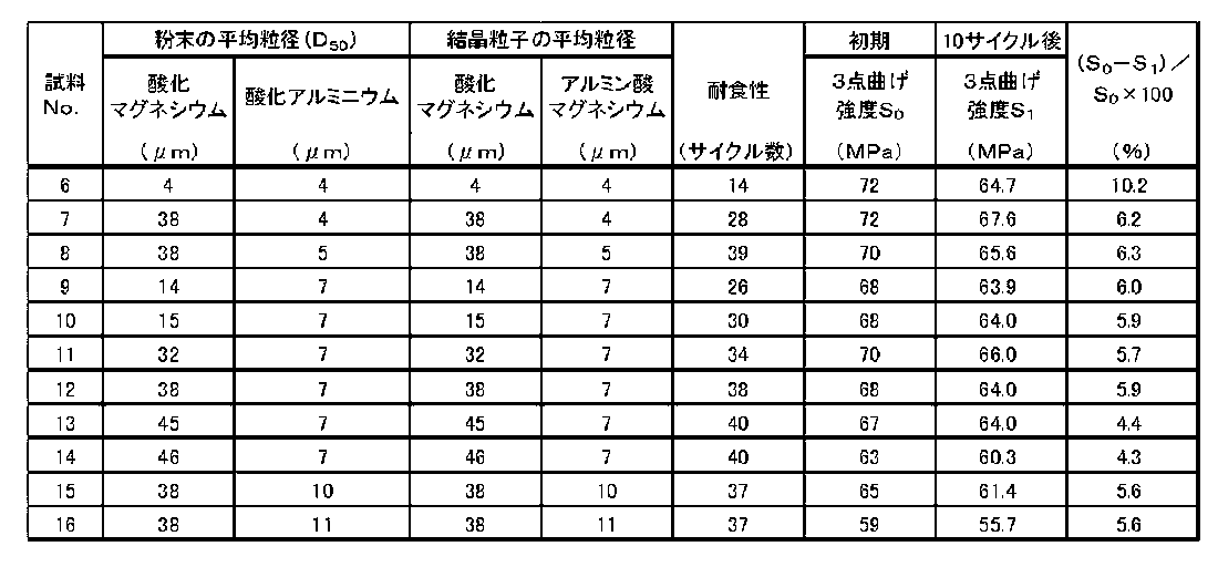
表2に示す結果から分かるように、試料No.7~16は、表面における酸化マグネシウムの結晶粒子の平均粒径が、アルミン酸マグネシウムの結晶粒子の平均粒径よりも大きいことから、アルカリ成分に対する耐食性が高いと言える。また、試料No.7~16は耐食性が高いことから3点曲げ強度の低下率も小さい。
また、酸化マグネシウムの結晶粒子の平均粒径が同じである試料No.7,8,12,15,16を比べると、試料No.8,12,15は、アルミン酸マグネシウムの結晶粒子の平均粒径が5μm以上10μm以下であることから、上記平均粒径が5μm未満である試料No.7よりもアルカリ成分に対する耐食性が高いと言える。
また、アルミン酸マグネシウムの結晶粒子の平均粒径が同じである試料No.9~14を比べると、試料No.10~13は、酸化マグネシウムの結晶粒子の平均粒径は、15μm以上45μm以下であることから、酸化マグネシウムの結晶粒子の平均粒径が15μm未満である試料No.9よりもアルカリ成分に対する耐食性が高く、酸化マグネシウムの結晶粒子の平均粒径が45μmを超える試料No.14よりも機械的強度が高いと言え、高い耐食性および高い機械的強度を兼ね備えていると言える。
実施例2で示した試料No.7と同じ方法を用いて幅,厚さおよび長さがそれぞれ4.4mm,3.3mm,40mmである柱状の成形体を得た
そして、柱状の成形体を電気炉内に配置した後、大気雰囲気中、表3に示す温度で10時間保持することによって気孔率がそれぞれ異なる焼結体を得た。これらの焼結体を研磨機により整形して、抗折試験片である試料No.17~22を得た。なお、焼成用部材の気孔率はアルキメデス法に準拠して求め、初期の機械的強度については抗折試験片の3点曲げ強度(S0)をJIS R 1601-2008に準拠して測定した。
そして、柱状の成形体を電気炉内に配置した後、大気雰囲気中、表3に示す温度で10時間保持することによって気孔率がそれぞれ異なる焼結体を得た。これらの焼結体を研磨機により整形して、抗折試験片である試料No.17~22を得た。なお、焼成用部材の気孔率はアルキメデス法に準拠して求め、初期の機械的強度については抗折試験片の3点曲げ強度(S0)をJIS R 1601-2008に準拠して測定した。
アルカリ成分に対する焼成用部材の機械的強度については、以下に示す方法で評価した。
まず、正極材料を構成する成分の1種であるニッケルコバルトマンガン酸リチウムの原料粉体である、組成式がLi2CO3として示される炭酸リチウムと、組成式がNi0.33Co0.34Mn0.33(OH)2として示される共沈水酸化ニッケルコバルトマンガンとを混合した粉末5gをそれぞれ上記焼成用部材の主面に載置した以外は実施例2と同様にして、3点曲げ強度(S1)を測定した。
これらの値を焼成用部材の3点曲げ強度であるとみなし、表3に示した。また、3点曲げ強度の低下率(ΔS)を算出し、その値を表3に示した。
なお、実施例3で得られる正極材料を構成する成分の1種であるニッケルコバルトマンガン酸リチウムは、実施例1で得られるコバルト酸リチウムよりも構成成分の種類が多いことから、焼成用部材は実施例1よりも浸食される危険性は高くなる。
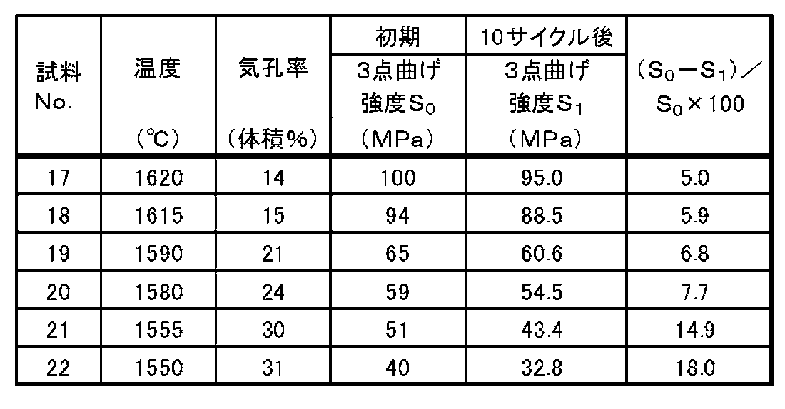
表3に示す結果から分かるように、試料No.17~21は、気孔率が30体積%以下であることから、気孔率が30%を超える試料No.22に比べ初期の機械的強度が高く、温度が高い状態でアルカリ成分と接触してもその低下率(ΔS)が低いと言える。
実施例2で示した試料No.7と同じ方法を用いて幅,厚さおよび長さがそれぞれ4.4mm,3.3mm,40mmである柱状の成形体を得た。
そして、柱状の成形体を電気炉内に配置した後、大気雰囲気中、最高温度を1585℃として、表4に示す時間で保持することによって平均気孔径がそれぞれ異なる焼結体を得た。この焼結体を研磨機により整形して、抗折試験片である試料No.23~27を得た。
アルカリ成分に対する焼成用部材の機械的強度については、実施例3に示した方法と同じ方法を用いて評価し、各試料の平均気孔径を水銀圧入法に準拠して求めた。
抗折試験片の初期および温度が高い状態でアルカリ成分と接触した後の機械的強度については、実施例3で示した方法と同じ方法を用いて求めた。また、3点曲げ強度の低下率(ΔS)を算出した。測定および算出したこれらの値を表4に示した。

表4に示す結果から分かるように、試料No.23~26は、平均気孔径が3μm以下であることから、平均気孔径が3μmを超える試料No.27に比べ初期の機械的強度が高く、温度が高い状態でリチウム成分と接触した後もその低下率(ΔS)が低いと言える。
まず、焼成用部材を構成する成分である酸化マグネシウムおよびアルミン酸マグネシウムがそれぞれ51質量%,49質量%となるように、酸化マグネシウムおよび酸化アルミニウムの各粉末をそれぞれ65質量%,35質量%として調合した。なお、酸化アルミニウムの粉末の平均粒径(D50)は1.4μmとし、酸化マグネシウムの平均粒径(D50)は、表5に示す通りとした。
調合した粉末に、可塑剤,増粘剤,滑り剤,分散剤,有機バインダおよび2-プロパノールを加えて、湿式混合し、粉砕してスラリーとした。
そして、得られたスラリーを噴霧乾燥法を用いて乾燥して顆粒を得た。次に、加圧成形法を用い、上記顆粒を基板状の成形体を得るための成形型および柱状の成形体を得るための成形型にそれぞれ充填してから、圧力を80MPaとして加圧することによって、1辺が330mmである正方形状の基板状の成形体と、幅,厚さおよび長さがそれぞれ5mm,3.8mm,45mmである柱状の成形体とを得た。
そして、成形体を電気炉内に配置した後、大気雰囲気中、温度を1585℃,5時間保持することによって焼結体を得た。これらの焼結体を研磨機により整形して、焼成用部材および抗折試験片である試料No.28~32を得た。
ここで、焼結体に含まれる酸化マグネシウムおよびアルミン酸マグネシウムは、X線回折法を用いて同定した。
そして、酸化マグネシウムの結晶粒子の平均粒径は、走査型電子顕微鏡を用い、倍率を1000倍、加速電圧を15kVとして、表面を含む、炭素で蒸着された破断面を撮影した反射電子組成像を用いた。この反射電子組成像を、画像解析ソフト「IMAGE-PRO PLUS」(登録商標、MEDIA CYBERNETICS社製)を用い、サンプル数を30として円相当径で算出し、その算出した数値を平均することによって、酸化マグネシウムの結晶粒子の平均粒径を求めた。
また、焼成用部材の初期の機械的強度については、抗折試験片の4点曲げ強度をJIS R 1601-2008に準拠して測定し、その測定値を焼成用部材の初期の機械的強度とみなした。これらの測定結果を表5に示した。

表5に示す結果から分かるように、酸化マグネシウムの結晶粒子の平均粒径が12μmを超える試料No.32に比べ試料No.28~31は、酸化マグネシウムの結晶粒子の平均粒径が10μm以下であることから、初期の機械的強度が高くなっていると言える。
まず、焼成用部材を構成する成分である酸化マグネシウム,アルミン酸マグネシウムならびにリチウム,コバルト,マンガン,ニッケルおよびリンの少なくともいずれか1種(以下、添加成分という。)がそれぞれ61質量%,35質量%,4質量%となるように、酸化マグネシウム,酸化アルミニウムおよび添加成分の各粉末をそれぞれ71質量%,25質量%,4質量%として調合した。
そして、基板状の成形体を得るまでは実施例1に示した方法と同じ方法で行なった。
そして、基板状の成形体を電気炉内に配置した後、大気雰囲気中、温度を1560℃,10時間保持することによって焼結体を得た。これらの焼結体を研磨機により整形して、焼成用部材である試料No.34~41および43~45とした。また、添加成分を含まない実施例1で作製した試料No.5の焼成用部材を比較例として、試料No.33および42とした。
焼成用部材の酸化マグネシウムおよびアルミン酸マグネシウムの各含有量は、実施例1で示した方法と同じ方法で求めた。また、添加成分の含有量は、ICP(Inductively Coupled Plasma)発光分光分析法によって求めた。これらの各成分の含有量を表6に示す。
アルカリ成分に対する焼成用部材の耐食性については、以下に示す方法で評価した。
表6に示すリチウムイオン2次電池の正極材料を構成する主成分を焼成するための各種粉末を混合した粉末20gをそれぞれ上記焼成用部材の主面に載置した以外は実施例1と同様にして耐食性の評価を実施し、その結果を表6に示した。

表6に示す結果から分かるように、試料No.34~41,43~45は、リチウム,コバルト,マンガン,ニッケルおよびリンの少なくともいずれか1種を含むことから、劣化しにくくなっていることが分かる。
まず、図9に示す焼成用容器18である試料No.46~52を作製した。また、試料No.46~52に用いた枠体2は、コージェライトを主成分とし、ムライトを副成分とした。また、試料No.46~52に用いた支持体1,定置部材40および基体41は、いずれも酸化マグネシウムを主成分とし、アルミン酸マグネシウムを副成分とするもので、支持体2の下面には、エポキシ系接着剤により基体41を接合した。
そして、コバルト酸リチウムの原料粉体の成分である酸化リチウムおよび酸化コバルトの各粉末を混合した粉末20gをそれぞれの支持体2の上面に載置して、連続式焼成炉(ローラーハースキルン)内で最高温度と保持時間とをそれぞれ、1000℃,3時間とし、その後常温まで冷却した後、匣鉢を反転して焼成物を取り出すというプロセスを1サイクルとして、このサイクルを繰り返した。定置部材40に亀裂が目視で初めて観察されたサイクル数を表7に示した。
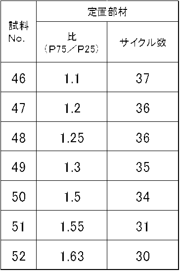
表7に示す結果からわかるように、定置部材40の気孔の気孔径(P25)および(P75)の比(P75/P25)が1.1以上1.5以下である試料No.46~50は、定置部材8の気孔のばらつきが抑制されていることで、耐熱衝撃性および機械的特性がともに高くなり、また焼成に繰り返して用いても、定置部材40に亀裂がより生じにくくなっていると言える。
1:支持体
2:枠体
3:接着剤
4:貫通孔
5:ボルト
6:ナット
7:ピン
8:配置面
9:内側面
40:定置部材
41:基体
10~18:焼成用容器
2:枠体
3:接着剤
4:貫通孔
5:ボルト
6:ナット
7:ピン
8:配置面
9:内側面
40:定置部材
41:基体
10~18:焼成用容器
Claims (20)
- 酸化マグネシウムを主成分とし、金属酸マグネシウムを副成分とする複合セラミックスからなることを特徴とする焼成用部材。
- 前記金属酸マグネシウムがアルミン酸マグネシウムであることを特徴とする請求項1に記載の焼成用部材。
- 表面における前記酸化マグネシウムの結晶粒子の平均粒径が、前記アルミン酸マグネシウムの結晶粒子の平均粒径よりも大きいことを特徴とする請求項2に記載の焼成用部材。
- 前記アルミン酸マグネシウムの結晶粒子の平均粒径が、5μm以上10μm以下であることを特徴とする請求項3に記載の焼成用部材。
- 前記酸化マグネシウムの結晶粒子の平均粒径が、45μm以下であることを特徴とする請求項2乃至請求項4のいずれかに記載の焼成用部材。
- 気孔率が30体積%以下であることを特徴とする請求項1乃至請求項5のいずれかに記載の焼成用部材。
- 平均気孔径が3μm以下であることを特徴とする請求項1乃至請求項6のいずれかに記載の焼成用部材。
- さらに、リチウム,コバルト,マンガン,ニッケルおよびリンの少なくともいずれか1種を含むことを特徴とする請求項1乃至請求項7のいずれかに記載の焼成用部材。
- 請求項1乃至請求項8のいずれかに記載の焼成用部材からなる支持体と、該支持体を収容するキャビティ部が設けられた枠体とを備えてなることを特徴とする焼成用容器。
- 前記枠体の側方に位置する側壁が、前記支持体の一端部を挿入するための第1貫通部を有するとともに、該第1貫通部に着脱可能に取り付けられた第1封止材を備えることを特徴とする請求項9に記載の焼成用容器。
- 前記側壁が、前記第1貫通部と対向して前記支持体の他端部を挿入するための第2貫通部を有するとともに、該第2貫通部に着脱可能に取り付けられる第2封止材を備えることを特徴とする請求項10に記載の焼成用容器。
- 前記支持体が、前記第1貫通部および前記第2貫通部の少なくとも一方を介して前記キャビティ部外に取り出し可能な大きさに形成されていることを特徴とする請求項11に記載の焼成用容器。
- 前記支持体が、前記第1封止材および前記第2封止材の少なくとも一方と空間をあけて配置されていることを特徴とする請求項11または請求項12に記載の焼成用容器。
- 前記支持体が、前記枠体の底面と空間をあけて配置されていることを特徴とする請求項9乃至請求項13のいずれかに記載の焼成用容器。
- 前記枠体の側方に位置する側壁が、前記キャビティ部内とつながる第3貫通部を有するとともに、一端が前記第3貫通部内に位置し、かつ他端が前記キャビティ部内に位置するように配置された、前記支持体を上方から前記キャビティ部に定置するための定置部材を備えることを特徴とする請求項9に記載の焼成用容器。
- 前記側壁が、該側壁の平均厚みより厚い厚肉部を有するとともに、該厚肉部に前記第3貫通部が設けられていることを特徴とする請求項15に記載の焼成用容器。
- 前記定置部材がセラミックスからなり、前記支持体の気孔率が、前記定置部材の気孔率よりも高いことを特徴とする請求項15乃至請求項16のいずれかに記載の焼成用容器。
- 前記定置部材の気孔が、気孔径の累積分布曲線における累積25体積%の気孔径(P25)に対する累積75体積%の気孔径(P75)の比(P75/P25)が1.1以上1.5以下であることを特徴とする請求項17に記載の焼成用容器。
- 前記枠体がセラミックスからなり、該セラミックスがコージェライトを主成分とすることを特徴とする請求項9乃至請求項18のいずれかに記載の焼成用容器。
- アルカリ成分を含む原料粉体を請求項9乃至請求項19のいずれかに記載の焼成用容器の前記支持体に載置して焼成する工程を有する正極材料の製造方法。
Priority Applications (1)
| Application Number | Priority Date | Filing Date | Title |
|---|---|---|---|
| JP2013507668A JPWO2012133525A1 (ja) | 2011-03-30 | 2012-03-28 | 焼成用部材およびこれを用いた焼成用容器ならびに正極材料の製造方法 |
Applications Claiming Priority (6)
| Application Number | Priority Date | Filing Date | Title |
|---|---|---|---|
| JP2011-075555 | 2011-03-30 | ||
| JP2011075555 | 2011-03-30 | ||
| JP2011-189092 | 2011-08-31 | ||
| JP2011189092 | 2011-08-31 | ||
| JP2011-276539 | 2011-12-17 | ||
| JP2011276539 | 2011-12-17 |
Publications (1)
| Publication Number | Publication Date |
|---|---|
| WO2012133525A1 true WO2012133525A1 (ja) | 2012-10-04 |
Family
ID=46931234
Family Applications (1)
| Application Number | Title | Priority Date | Filing Date |
|---|---|---|---|
| PCT/JP2012/058121 Ceased WO2012133525A1 (ja) | 2011-03-30 | 2012-03-28 | 焼成用部材およびこれを用いた焼成用容器ならびに正極材料の製造方法 |
Country Status (2)
| Country | Link |
|---|---|
| JP (1) | JPWO2012133525A1 (ja) |
| WO (1) | WO2012133525A1 (ja) |
Cited By (8)
| Publication number | Priority date | Publication date | Assignee | Title |
|---|---|---|---|---|
| WO2020104592A1 (de) * | 2018-11-21 | 2020-05-28 | Saint-Gobain Industriekeramik Rödental GmbH | Transportwanne zum transportieren und erhitzen chemischer substanzen |
| WO2021153400A1 (ja) * | 2020-01-30 | 2021-08-05 | パナソニックIpマネジメント株式会社 | リチウム遷移金属複合酸化物の製造方法 |
| WO2021151917A1 (de) * | 2020-01-28 | 2021-08-05 | Saint-Gobain Industriekeramik Rödental GmbH | Transportwanne zum transportieren und erhitzen chemischer substanzen |
| CN113277835A (zh) * | 2020-02-20 | 2021-08-20 | 广州市尤特新材料有限公司 | 定位工装和平面靶材的烧结方法 |
| US11152603B2 (en) | 2016-06-13 | 2021-10-19 | Research Institute Of Industrial Science & Technology | Saggar for firing active material of lithium secondary battery, and method for manufacturing active material using same |
| CN114195504A (zh) * | 2021-11-05 | 2022-03-18 | 中山大学 | 一种MgAl2O4纳米线膜的制备方法和应用 |
| JP7090784B1 (ja) | 2021-11-18 | 2022-06-24 | 日本碍子株式会社 | 熱処理システム、それが備える匣鉢及び熱処理方法 |
| SE2351019A1 (en) * | 2023-08-31 | 2025-03-01 | Northvolt Ab | A saggar having a replaceable base for use in battery manufacturing |
Citations (5)
| Publication number | Priority date | Publication date | Assignee | Title |
|---|---|---|---|---|
| JP2004063261A (ja) * | 2002-07-29 | 2004-02-26 | Noritake Co Ltd | 正極原料焼成用耐火物とその利用 |
| JP2006029611A (ja) * | 2004-07-12 | 2006-02-02 | Noritake Co Ltd | 板状構造体およびその製造方法 |
| JP2007112670A (ja) * | 2005-10-21 | 2007-05-10 | Toshiba Ceramics Co Ltd | 焼成容器 |
| JP2008103100A (ja) * | 2006-10-17 | 2008-05-01 | Matsushita Electric Ind Co Ltd | 非水電解質二次電池用正極活物質およびその焼成用治具 |
| JP2010241625A (ja) * | 2009-04-03 | 2010-10-28 | Maruei Sangyo Gousakusha Co Ltd | 耐蝕性焼成治具及びその製造方法 |
-
2012
- 2012-03-28 JP JP2013507668A patent/JPWO2012133525A1/ja active Pending
- 2012-03-28 WO PCT/JP2012/058121 patent/WO2012133525A1/ja not_active Ceased
Patent Citations (5)
| Publication number | Priority date | Publication date | Assignee | Title |
|---|---|---|---|---|
| JP2004063261A (ja) * | 2002-07-29 | 2004-02-26 | Noritake Co Ltd | 正極原料焼成用耐火物とその利用 |
| JP2006029611A (ja) * | 2004-07-12 | 2006-02-02 | Noritake Co Ltd | 板状構造体およびその製造方法 |
| JP2007112670A (ja) * | 2005-10-21 | 2007-05-10 | Toshiba Ceramics Co Ltd | 焼成容器 |
| JP2008103100A (ja) * | 2006-10-17 | 2008-05-01 | Matsushita Electric Ind Co Ltd | 非水電解質二次電池用正極活物質およびその焼成用治具 |
| JP2010241625A (ja) * | 2009-04-03 | 2010-10-28 | Maruei Sangyo Gousakusha Co Ltd | 耐蝕性焼成治具及びその製造方法 |
Cited By (20)
| Publication number | Priority date | Publication date | Assignee | Title |
|---|---|---|---|---|
| US11152603B2 (en) | 2016-06-13 | 2021-10-19 | Research Institute Of Industrial Science & Technology | Saggar for firing active material of lithium secondary battery, and method for manufacturing active material using same |
| US12055347B2 (en) | 2018-11-21 | 2024-08-06 | Saint-Gobain Industriekeramik Rödental GmbH | Transport trough for transporting and heating of chemical substances |
| CN113272460A (zh) * | 2018-11-21 | 2021-08-17 | 圣戈班工业陶瓷罗登塔尔有限责任公司 | 用于化学物质的运输和加热的运输盆 |
| WO2020104592A1 (de) * | 2018-11-21 | 2020-05-28 | Saint-Gobain Industriekeramik Rödental GmbH | Transportwanne zum transportieren und erhitzen chemischer substanzen |
| JP2022507862A (ja) * | 2018-11-21 | 2022-01-18 | サン-ゴバン インドゥストリーケラミク レーデンタール ゲゼルシャフト ミット ベシュレンクテル ハフツング | 化学物質の輸送及び加熱のための輸送トラフ |
| JP7331104B2 (ja) | 2018-11-21 | 2023-08-22 | サン-ゴバン インドゥストリーケラミク レーデンタール ゲゼルシャフト ミット ベシュレンクテル ハフツング | 化学物質の輸送及び加熱のための輸送トラフ |
| WO2021151917A1 (de) * | 2020-01-28 | 2021-08-05 | Saint-Gobain Industriekeramik Rödental GmbH | Transportwanne zum transportieren und erhitzen chemischer substanzen |
| US12270608B2 (en) * | 2020-01-28 | 2025-04-08 | Saint-Gobain Industriekeramik Rödental GmbH | Transportation tray for transporting and heating chemical substances |
| JP7356598B2 (ja) | 2020-01-28 | 2023-10-04 | サン-ゴバン インドゥストリーケラミク レーデンタール ゲゼルシャフト ミット ベシュレンクテル ハフツング | 化学物質を輸送し加熱するための輸送トレイ |
| US20230070101A1 (en) * | 2020-01-28 | 2023-03-09 | Saint-Gobain Industriekeramik Rödental GmbH | Transportation tray for transporting and heating chemical substances |
| JP2023511457A (ja) * | 2020-01-28 | 2023-03-17 | サン-ゴバン インドゥストリーケラミク レーデンタール ゲゼルシャフト ミット ベシュレンクテル ハフツング | 化学物質を輸送し加熱するための輸送トレイ |
| JPWO2021153400A1 (ja) * | 2020-01-30 | 2021-08-05 | ||
| WO2021153400A1 (ja) * | 2020-01-30 | 2021-08-05 | パナソニックIpマネジメント株式会社 | リチウム遷移金属複合酸化物の製造方法 |
| CN113277835A (zh) * | 2020-02-20 | 2021-08-20 | 广州市尤特新材料有限公司 | 定位工装和平面靶材的烧结方法 |
| CN113277835B (zh) * | 2020-02-20 | 2022-10-11 | 广州市尤特新材料有限公司 | 定位工装和平面靶材的烧结方法 |
| CN114195504A (zh) * | 2021-11-05 | 2022-03-18 | 中山大学 | 一种MgAl2O4纳米线膜的制备方法和应用 |
| JP2023074931A (ja) * | 2021-11-18 | 2023-05-30 | 日本碍子株式会社 | 熱処理システム、それが備える匣鉢及び熱処理方法 |
| JP7090784B1 (ja) | 2021-11-18 | 2022-06-24 | 日本碍子株式会社 | 熱処理システム、それが備える匣鉢及び熱処理方法 |
| SE2351019A1 (en) * | 2023-08-31 | 2025-03-01 | Northvolt Ab | A saggar having a replaceable base for use in battery manufacturing |
| WO2025046096A1 (en) * | 2023-08-31 | 2025-03-06 | Northvolt Ab | A saggar having a replaceable base for use in battery manufacturing |
Also Published As
| Publication number | Publication date |
|---|---|
| JPWO2012133525A1 (ja) | 2014-07-28 |
Similar Documents
| Publication | Publication Date | Title |
|---|---|---|
| WO2012133525A1 (ja) | 焼成用部材およびこれを用いた焼成用容器ならびに正極材料の製造方法 | |
| ES2973278T3 (es) | Electrolitos de granate rellenos de litio con inclusiones de fase secundaria | |
| US9733019B2 (en) | Container for heat treatment of positive-electrode active material for lithium-ion battery and method for producing the same | |
| JP5742941B2 (ja) | 全固体電池およびその製造方法 | |
| JP7546365B2 (ja) | 軽量窯道具及びその製造方法 | |
| JP7062230B2 (ja) | 板状の窒化ケイ素質焼結体およびその製造方法 | |
| JP2011178598A (ja) | 窒化珪素基板の製造方法および窒化珪素基板 | |
| TW201107268A (en) | Method for producing aluminum titanate ceramic body | |
| EP2080743A1 (en) | Ceramic pug and use thereof | |
| CN104659397A (zh) | 固体氧化物型燃料电池用氧化锆片和包含该片的固体氧化物型燃料电池用单电池 | |
| CN112912356B (zh) | 氮化硅基板的制造方法以及氮化硅基板 | |
| JP4357584B1 (ja) | 耐食性、耐熱衝撃抵抗性及び耐久性に優れたアルミナ質焼結体 | |
| US12065383B2 (en) | Oriented ceramic sintered body production method and flat sheet | |
| KR20230084909A (ko) | 이차전지 양극활물질용 소성 용기 및 이의 제조 방법 | |
| JP7333486B2 (ja) | セラミックス焼成用セッター | |
| JP6025586B2 (ja) | セッターの製造方法 | |
| JP6402131B2 (ja) | 焼成治具の製造方法 | |
| JP5092135B2 (ja) | 多孔質体およびその製造方法 | |
| JP5438345B2 (ja) | 焼成用治具 | |
| JP6067394B2 (ja) | 焼成治具 | |
| JP7602892B2 (ja) | 軽量窯道具及びその製造方法 | |
| JP2014024740A (ja) | セラミック焼結体および熱処理用部材 | |
| JP2013193891A (ja) | 窒化アルミニウム焼結体の製造方法 | |
| JP2005314170A (ja) | ロータリーキルン | |
| EP1736457B1 (en) | Ceramic clay, manufacturing methods thereof and manufacturing methods for ceramic formed article and ceramic structure, |
Legal Events
| Date | Code | Title | Description |
|---|---|---|---|
| 121 | Ep: the epo has been informed by wipo that ep was designated in this application |
Ref document number: 12763253 Country of ref document: EP Kind code of ref document: A1 |
|
| ENP | Entry into the national phase |
Ref document number: 2013507668 Country of ref document: JP Kind code of ref document: A |
|
| NENP | Non-entry into the national phase |
Ref country code: DE |
|
| 122 | Ep: pct application non-entry in european phase |
Ref document number: 12763253 Country of ref document: EP Kind code of ref document: A1 |