WO2012127895A1 - Dispositif d'étanchéité - Google Patents
Dispositif d'étanchéité Download PDFInfo
- Publication number
- WO2012127895A1 WO2012127895A1 PCT/JP2012/051023 JP2012051023W WO2012127895A1 WO 2012127895 A1 WO2012127895 A1 WO 2012127895A1 JP 2012051023 W JP2012051023 W JP 2012051023W WO 2012127895 A1 WO2012127895 A1 WO 2012127895A1
- Authority
- WO
- WIPO (PCT)
- Prior art keywords
- sealing device
- lip
- seal lip
- seal
- grease
- Prior art date
Links
Images


Classifications
-
- F—MECHANICAL ENGINEERING; LIGHTING; HEATING; WEAPONS; BLASTING
- F16—ENGINEERING ELEMENTS AND UNITS; GENERAL MEASURES FOR PRODUCING AND MAINTAINING EFFECTIVE FUNCTIONING OF MACHINES OR INSTALLATIONS; THERMAL INSULATION IN GENERAL
- F16J—PISTONS; CYLINDERS; SEALINGS
- F16J15/00—Sealings
- F16J15/16—Sealings between relatively-moving surfaces
- F16J15/32—Sealings between relatively-moving surfaces with elastic sealings, e.g. O-rings
- F16J15/324—Arrangements for lubrication or cooling of the sealing itself
-
- C—CHEMISTRY; METALLURGY
- C10—PETROLEUM, GAS OR COKE INDUSTRIES; TECHNICAL GASES CONTAINING CARBON MONOXIDE; FUELS; LUBRICANTS; PEAT
- C10M—LUBRICATING COMPOSITIONS; USE OF CHEMICAL SUBSTANCES EITHER ALONE OR AS LUBRICATING INGREDIENTS IN A LUBRICATING COMPOSITION
- C10M171/00—Lubricating compositions characterised by purely physical criteria, e.g. containing as base-material, thickener or additive, ingredients which are characterised exclusively by their numerically specified physical properties, i.e. containing ingredients which are physically well-defined but for which the chemical nature is either unspecified or only very vaguely indicated
- C10M171/02—Specified values of viscosity or viscosity index
-
- F—MECHANICAL ENGINEERING; LIGHTING; HEATING; WEAPONS; BLASTING
- F16—ENGINEERING ELEMENTS AND UNITS; GENERAL MEASURES FOR PRODUCING AND MAINTAINING EFFECTIVE FUNCTIONING OF MACHINES OR INSTALLATIONS; THERMAL INSULATION IN GENERAL
- F16C—SHAFTS; FLEXIBLE SHAFTS; ELEMENTS OR CRANKSHAFT MECHANISMS; ROTARY BODIES OTHER THAN GEARING ELEMENTS; BEARINGS
- F16C33/00—Parts of bearings; Special methods for making bearings or parts thereof
- F16C33/72—Sealings
- F16C33/76—Sealings of ball or roller bearings
- F16C33/78—Sealings of ball or roller bearings with a diaphragm, disc, or ring, with or without resilient members
- F16C33/7816—Details of the sealing or parts thereof, e.g. geometry, material
- F16C33/782—Details of the sealing or parts thereof, e.g. geometry, material of the sealing region
- F16C33/7823—Details of the sealing or parts thereof, e.g. geometry, material of the sealing region of sealing lips
-
- F—MECHANICAL ENGINEERING; LIGHTING; HEATING; WEAPONS; BLASTING
- F16—ENGINEERING ELEMENTS AND UNITS; GENERAL MEASURES FOR PRODUCING AND MAINTAINING EFFECTIVE FUNCTIONING OF MACHINES OR INSTALLATIONS; THERMAL INSULATION IN GENERAL
- F16C—SHAFTS; FLEXIBLE SHAFTS; ELEMENTS OR CRANKSHAFT MECHANISMS; ROTARY BODIES OTHER THAN GEARING ELEMENTS; BEARINGS
- F16C33/00—Parts of bearings; Special methods for making bearings or parts thereof
- F16C33/72—Sealings
- F16C33/76—Sealings of ball or roller bearings
- F16C33/78—Sealings of ball or roller bearings with a diaphragm, disc, or ring, with or without resilient members
- F16C33/7869—Sealings of ball or roller bearings with a diaphragm, disc, or ring, with or without resilient members mounted with a cylindrical portion to the inner surface of the outer race and having a radial portion extending inward
- F16C33/7879—Sealings of ball or roller bearings with a diaphragm, disc, or ring, with or without resilient members mounted with a cylindrical portion to the inner surface of the outer race and having a radial portion extending inward with a further sealing ring
- F16C33/7883—Sealings of ball or roller bearings with a diaphragm, disc, or ring, with or without resilient members mounted with a cylindrical portion to the inner surface of the outer race and having a radial portion extending inward with a further sealing ring mounted to the inner race and of generally L-shape, the two sealing rings defining a sealing with box-shaped cross-section
-
- F—MECHANICAL ENGINEERING; LIGHTING; HEATING; WEAPONS; BLASTING
- F16—ENGINEERING ELEMENTS AND UNITS; GENERAL MEASURES FOR PRODUCING AND MAINTAINING EFFECTIVE FUNCTIONING OF MACHINES OR INSTALLATIONS; THERMAL INSULATION IN GENERAL
- F16J—PISTONS; CYLINDERS; SEALINGS
- F16J15/00—Sealings
- F16J15/16—Sealings between relatively-moving surfaces
- F16J15/32—Sealings between relatively-moving surfaces with elastic sealings, e.g. O-rings
- F16J15/3248—Sealings between relatively-moving surfaces with elastic sealings, e.g. O-rings provided with casings or supports
- F16J15/3252—Sealings between relatively-moving surfaces with elastic sealings, e.g. O-rings provided with casings or supports with rigid casings or supports
- F16J15/3256—Sealings between relatively-moving surfaces with elastic sealings, e.g. O-rings provided with casings or supports with rigid casings or supports comprising two casing or support elements, one attached to each surface, e.g. cartridge or cassette seals
- F16J15/3264—Sealings between relatively-moving surfaces with elastic sealings, e.g. O-rings provided with casings or supports with rigid casings or supports comprising two casing or support elements, one attached to each surface, e.g. cartridge or cassette seals the elements being separable from each other
-
- C—CHEMISTRY; METALLURGY
- C10—PETROLEUM, GAS OR COKE INDUSTRIES; TECHNICAL GASES CONTAINING CARBON MONOXIDE; FUELS; LUBRICANTS; PEAT
- C10N—INDEXING SCHEME ASSOCIATED WITH SUBCLASS C10M RELATING TO LUBRICATING COMPOSITIONS
- C10N2020/00—Specified physical or chemical properties or characteristics, i.e. function, of component of lubricating compositions
- C10N2020/01—Physico-chemical properties
- C10N2020/02—Viscosity; Viscosity index
-
- C—CHEMISTRY; METALLURGY
- C10—PETROLEUM, GAS OR COKE INDUSTRIES; TECHNICAL GASES CONTAINING CARBON MONOXIDE; FUELS; LUBRICANTS; PEAT
- C10N—INDEXING SCHEME ASSOCIATED WITH SUBCLASS C10M RELATING TO LUBRICATING COMPOSITIONS
- C10N2030/00—Specified physical or chemical properties which is improved by the additive characterising the lubricating composition, e.g. multifunctional additives
- C10N2030/06—Oiliness; Film-strength; Anti-wear; Resistance to extreme pressure
-
- C—CHEMISTRY; METALLURGY
- C10—PETROLEUM, GAS OR COKE INDUSTRIES; TECHNICAL GASES CONTAINING CARBON MONOXIDE; FUELS; LUBRICANTS; PEAT
- C10N—INDEXING SCHEME ASSOCIATED WITH SUBCLASS C10M RELATING TO LUBRICATING COMPOSITIONS
- C10N2040/00—Specified use or application for which the lubricating composition is intended
- C10N2040/02—Bearings
-
- C—CHEMISTRY; METALLURGY
- C10—PETROLEUM, GAS OR COKE INDUSTRIES; TECHNICAL GASES CONTAINING CARBON MONOXIDE; FUELS; LUBRICANTS; PEAT
- C10N—INDEXING SCHEME ASSOCIATED WITH SUBCLASS C10M RELATING TO LUBRICATING COMPOSITIONS
- C10N2050/00—Form in which the lubricant is applied to the material being lubricated
- C10N2050/10—Semi-solids; greasy
-
- F—MECHANICAL ENGINEERING; LIGHTING; HEATING; WEAPONS; BLASTING
- F16—ENGINEERING ELEMENTS AND UNITS; GENERAL MEASURES FOR PRODUCING AND MAINTAINING EFFECTIVE FUNCTIONING OF MACHINES OR INSTALLATIONS; THERMAL INSULATION IN GENERAL
- F16C—SHAFTS; FLEXIBLE SHAFTS; ELEMENTS OR CRANKSHAFT MECHANISMS; ROTARY BODIES OTHER THAN GEARING ELEMENTS; BEARINGS
- F16C2240/00—Specified values or numerical ranges of parameters; Relations between them
- F16C2240/40—Linear dimensions, e.g. length, radius, thickness, gap
- F16C2240/54—Surface roughness
-
- F—MECHANICAL ENGINEERING; LIGHTING; HEATING; WEAPONS; BLASTING
- F16—ENGINEERING ELEMENTS AND UNITS; GENERAL MEASURES FOR PRODUCING AND MAINTAINING EFFECTIVE FUNCTIONING OF MACHINES OR INSTALLATIONS; THERMAL INSULATION IN GENERAL
- F16C—SHAFTS; FLEXIBLE SHAFTS; ELEMENTS OR CRANKSHAFT MECHANISMS; ROTARY BODIES OTHER THAN GEARING ELEMENTS; BEARINGS
- F16C2326/00—Articles relating to transporting
- F16C2326/20—Land vehicles
Definitions
- the present invention relates to a sealing device, and more particularly to a sealing device having a seal lip that is slidably in close contact with a mating member.
- the sealing device of the present invention is used, for example, as a bearing grease seal or the like in the field related to automobiles.
- a sealing device (hereinafter also referred to as a seal) is used for the purpose of preventing muddy water from entering from outside and sealing bearing grease.
- the present invention provides a sealing device having a sealing lip that is slidably in close contact with a mating member, and can achieve low friction accompanying the sliding and also suppress lip wear.
- An object of the present invention is to provide a sealing device that can be used.
- a sealing device is a sealing device having a sealing lip that is slidably in contact with a mating member, and simultaneously reduces frictional force and suppresses lip wear in the sliding.
- the sliding surface of the seal lip is provided with irregularities, and a low base oil viscosity grease is supplied to the sliding surface of the seal lip.
- the sealing device according to claim 2 of the present invention is the sealing device according to claim 1, wherein the mating member is integrally formed with a flange portion radially outward from one axial end of the cylindrical portion.
- a slinger having a substantially L-shaped cross section, wherein the seal lip is slidably in close contact with the end surface of the flange portion, and a second seal is slidably in close contact with the outer peripheral surface of the cylindrical portion.
- a lip and a third seal lip that is slidably in close contact with the outer peripheral surface of the cylindrical portion inside the second seal lip, and the unevenness is imparted to the sliding surfaces of the three seal lips, respectively.
- the low base oil viscosity grease is filled in the space between the three seal lips.
- the sealing device according to claim 3 of the present invention is the sealing device according to claim 1 or 2, characterized in that the unevenness has a size of 1.0 to 3.0 ⁇ mRa.
- the sealing device according to claim 4 of the present invention is the sealing device according to claim 1 or 2, characterized in that the unevenness has a size of 1.5 to 3.0 ⁇ mRa.
- the sealing device according to claim 5 of the present invention is the sealing device according to claim 1, 2, 3 or 4, wherein the low base oil viscosity grease has a base oil kinematic viscosity at 40 ° C. of 10 to 10. It is characterized by being a grease of 40 mm 2 / s.
- the sliding surface of the seal lip is provided with irregularities, and the low base oil viscosity grease is supplied to the sliding surface of the seal lip.
- the provision of irregularities here means that the irregularities are formed in advance, and that the grease is supplied means that the grease performs a lubricating action during the lip sliding operation as a result.
- the irregularities are fine irregularities.
- the contact area of the seal lip with the mating member is reduced, and grease is likely to intervene due to the unevenness, so the frictional force is reduced and the low base oil viscosity as grease Since the grease is supplied, the frictional force is further reduced.
- the surface of the mating member is formed as a smooth surface having a normal surface roughness. ing. Accordingly, the seal lip made of rubber-like elastic material slides on a smooth surface rather than an uneven surface, and therefore the seal lip is less likely to slide and wear.
- the mating member with which the seal lip is slidably in close contact is, for example, a half-section substantially L-shaped in which a flange portion is integrally formed from one axial end of the cylindrical portion outward in the radial direction.
- a slinger As the seal lip, for example, a first seal lip that is slidably in contact with the end surface of the flange portion of the slinger, a second seal lip that is slidably in close contact with the outer peripheral surface of the cylindrical portion, and a second seal lip And a third seal lip that is slidably in close contact with the outer peripheral surface of the cylindrical portion.
- unevenness is imparted to the sliding surfaces of the three seal lips, and the space between the first seal lip and the second seal lip and the space between the second seal lip and the third seal lip are reduced.
- the base oil viscosity grease will be filled.
- the unevenness imparted to the surface of the mating member is optimal when the surface roughness is in the range of 0.5 to 1.5 ⁇ mRa.
- unevenness is imparted to the sliding surface of the seal lip instead of the surface of the member, it is necessary to change the surface roughness because the seal lip is easily elastically deformed.
- the surface roughness is It has been found that it is desirable to make the range larger than the above case, that is, 1.0 to 3.0 ⁇ m Ra, and 1.5 to 3.0 ⁇ m Ra (equivalent to 10 to 20 ⁇ m Rz) in view of practical use.
- the grease may be dispersed by sliding to cause an increase in frictional resistance, so the base oil kinematic viscosity at 40 ° C. is 10 mm 2 / s. It is desirable to use a larger one.
- Grease used for general bearings base oil kinematic viscosity at 40 ° C. is 60 to 100 mm 2 / s
- the present invention has the following effects.
- the sealing device of the present invention since the unevenness is imparted to the sliding surface of the seal lip, the contact area of the seal lip with the mating member is reduced and the grease is likely to be interposed by the unevenness, Therefore, the frictional force is reduced, and the low base oil viscosity grease is supplied as the grease, so that the frictional force is further reduced. Moreover, since the unevenness is imparted to the sliding surface of the seal lip and not to the surface of the mating member, the surface of the mating member is formed as a smooth surface having a normal surface roughness. Accordingly, the seal lip made of rubber-like elastic material slides on a smooth surface, not an uneven surface, and therefore the seal lip is less likely to slide and wear.
- a seal that can achieve low friction accompanying sliding and can also suppress lip wear.
- the present invention includes the following embodiments.
- (1) As shown in FIG. 1, the present invention is characterized in that the lip portion of the seal is provided with irregularities and is filled with a low base oil viscosity grease.
- the present invention relates to a method for reducing the torque of a bearing grease seal.
- (3) The present invention is different from the invention described in the prior art document in that the surface roughness on the rubber side is adjusted. The torque can be reduced by increasing the surface roughness on the rubber lip side.
- the surface roughness on the metal member side that comes into sliding contact with the rubber lip is a normal finished surface, there is an advantage that the lip does not wear. Further, since the lip roughness is formed by transferring the surface of the mold to a predetermined surface roughness, there is an advantage that the roughness quality can be kept constant. Since the surface of the rubber lip is greatly elastically deformed by sliding contact with the mating metal member, a numerical range different from the roughness of the surface formed on the metal member side, which has been performed so far, is an optimum range in the case of rubber. As is clear from the examples of the present invention, this optimum range cannot be easily conceived from the invention described in the prior art document.
- FIG. 1 shows a cross section of the main part of a sealing device according to an embodiment of the present invention.
- the sealing device shown in FIG. 1 is used as a bearing grease seal in the automobile-related field, and is attached to a bearing inner ring (not shown) and rotates together with the bearing inner ring, and a bearing outer ring (not shown). It is configured by a combination with a seal lip member 21 that is attached and slidably contacts the slinger 11.
- the bearing inner ring may be a shaft or sleeve of a rotating device instead of this
- the bearing outer ring may be a housing of a rotating device instead of this.
- the slinger 11 is made of a metal material, and is integrally formed with a flange portion (outward flange portion) 11b radially outward at one end in the axial direction of the cylindrical portion 11a so as to have a substantially L-shaped cross section.
- the inner peripheral surface of the cylindrical portion 11a is fitted to the outer peripheral surface of the bearing inner ring.
- a magnetic encoder may be attached to the outer end surface 11c of the flange portion 11b.
- the seal lip member 21 is configured by a combination of an attachment ring 22 and a rubber-like elastic body 23 attached to the attachment ring 22.
- the mounting ring 22 is made of a metal material, and is formed by integrally forming a flange portion (inward flange portion) 22b radially inward at the other axial end of the cylindrical portion 22a.
- the outer peripheral surface 22a is fitted to the inner peripheral surface of the bearing outer ring.
- the rubber-like elastic body 23 is slidably in close contact with the rubber part 24 attached to the attachment ring 22 and the inner end face 11d of the flange part 11b of the slinger 11 supported by the rubber part 24.
- a third seal lip (grease lip) 27 that is also supported by the adherend rubber portion 24 inside the seal lip 26 (inside the machine) and slidably contacts the outer peripheral surface of the cylindrical portion 11a of the slinger 11 is integrated.
- the first seal lip 25 and the second seal lip 26 seal the foreign matter such as muddy water outside the bearing from entering the bearing. Because of its function against muddy water, it has an outward lip structure (a structure in which the lip end is directed to the outside of the bearing), and in particular, the diameter of the first seal lip 25 gradually increases from the base end to the tip end. It is formed to do.
- the third seal lip 27 seals the grease inside the bearing so that it does not leak to the outside of the bearing.
- the third seal lip 27 has an inward lip structure (the lip end faces toward the inside of the bearing) due to the function of the grease. Structure).
- Unevenness (not shown) is provided on the sliding surfaces 25a, 26a, 27a of the three seal lips 25, 26, 27, respectively.
- the unevenness is set to a size of 1.0 to 3.0 ⁇ mRa. Since the unevenness is a minute shape and cannot be illustrated in FIG. 1, in FIG. 1, regions where the unevenness is provided are indicated by solid lines A, B, and C, respectively.
- a sealed space 31 is formed between the first seal lip 25 and the second seal lip 26, and the second seal lip 26 and the third seal lip 26
- a sealed space 32 is also formed between the seal lips 27.
- these spaces 31 and 32 are filled with low base oil viscosity grease (not shown), respectively. It is said that.
- the low base oil viscosity grease a grease having a base oil kinematic viscosity at 40 ° C. of 10 to 40 mm 2 / s is used.
- the surface of the slinger 11 is not provided with irregularities, that is, the surface of the slinger 11 is finished as a smooth surface having a normal surface roughness.
- the sliding surfaces 25a, 26a, and 27a of the seal lips 25, 26, and 27 are provided with irregularities and the spaces 31 and 32 between the seal lips 25, 26, and 27 have a low base.
- the low base oil viscosity grease is supplied to the sliding surfaces 25a, 26a, 27a of the seal lips 25, 26, 27. If unevenness is given to the sliding surfaces 25a, 26a, 27a of the seal lips 25, 26, 27, the contact area of the seal lips 25, 26, 27 to the slinger 11 is reduced, and grease is likely to intervene due to the unevenness.
- the frictional force can be reduced, and the low base oil viscosity grease is supplied as the grease, so that the frictional force can be further reduced.
- the unevenness is imparted to the sliding surfaces 25a, 26a, 27a of the seal lips 25, 26, 27 and not to the surface of the slinger 11, so that the surface of the slinger 11 has a normal surface roughness. It is finished as a smooth surface. Therefore, since the rubber-like elastic seal lips 25, 26, 27 slide on a smooth surface rather than an uneven surface, it is possible to suppress the sliding lip 25, 26, 27 from sliding wear. Become.
- a sealing device having a sealing lip that is slidably in close contact with a mating member as in the intended purpose of the present invention low friction caused by sliding can be realized and lip wear can be suppressed.
- Table 1 shows the effect of reducing the frictional force due to the unevenness on the seal lip.
- a general bearing grease base oil kinematic viscosity at 40 ° C. is 65 mm 2 / s
- the slinger is rotated at 500 rpm with the lip member fixed to the housing.
- the frictional force was measured.
- the relative comparison is made assuming that the frictional force at the seal not provided with unevenness is 100.
- the frictional force decreases as the surface roughness of the lip increases, and in the range where the surface roughness is larger than 3.0 ⁇ mRa (equivalent to 20 ⁇ mRz), the effect of reducing the frictional force is equivalent. It has become. Since imparting excessive roughness to the lip surface leads to a decrease in the sealing performance, the surface roughness of the lip portion is set to 1.0 to 3 in order to obtain a remarkable effect of reducing the frictional force while maintaining the sealing performance. From the viewpoint of practical use, it is preferably 1.5 to 3.0 ⁇ m Ra (equivalent to 10 to 20 ⁇ m Rz).
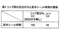
- Table 3 shows the effect of reducing the frictional force by providing irregularities on the seal lip and using the low base oil viscosity grease.
- the test conditions are the same as those shown in Table 1, and the frictional force of a seal that is not provided with irregularities with grease having a base oil kinematic viscosity at 40 ° C. of 65 mm 2 / s is 100.
- the drastic friction reduction effect can be anticipated by using a low base oil viscosity grease. This reduction in friction can be expected to improve fuel efficiency by reducing friction loss and to improve seal life by suppressing wear.
Landscapes
- Engineering & Computer Science (AREA)
- General Engineering & Computer Science (AREA)
- Mechanical Engineering (AREA)
- Chemical & Material Sciences (AREA)
- Chemical Kinetics & Catalysis (AREA)
- General Chemical & Material Sciences (AREA)
- Oil, Petroleum & Natural Gas (AREA)
- Organic Chemistry (AREA)
- Sealing Of Bearings (AREA)
- Sealing With Elastic Sealing Lips (AREA)
- Lubricants (AREA)
Abstract
L'invention porte sur un dispositif d'étanchéité ayant une lèvre d'étanchéité qui vient en contact de manière serrée avec l'autre élément de façon à être apte à coulisser librement, dans lequel il est possible de réduire le frottement qui accompagne le coulissement, et il est en outre possible de supprimer l'abrasion de la lèvre. Afin d'obtenir ce qui précède, le dispositif d'étanchéité ayant une lèvre d'étanchéité qui vient en contact de manière serrée avec l'autre élément de façon à être apte à coulisser librement est caractérisé en ce qu'une irrégularité est ajoutée à une surface de coulissement de la lèvre d'étanchéité et en ce que de la graisse avec une viscosité d'huile de base faible est délivrée sur la surface de coulissement de la lèvre d'étanchéité, de façon à réaliser ainsi simultanément une force de frottement plus faible pendant le coulissement et à supprimer une abrasion de la lèvre. L'irrégularité a une dimension de 1,0 à 3,0 µmRa et la graisse à viscosité d'huile de base faible est, de préférence, de la graisse ayant une viscosité d'huile de base dynamique de 10 à 40 mm2/s à 40°C.
Priority Applications (2)
| Application Number | Priority Date | Filing Date | Title |
|---|---|---|---|
| EP12760861.0A EP2687761B1 (fr) | 2011-03-18 | 2012-01-19 | Dispositif d'étanchéité |
| CN2012800134378A CN103459902A (zh) | 2011-03-18 | 2012-01-19 | 密封装置 |
Applications Claiming Priority (2)
| Application Number | Priority Date | Filing Date | Title |
|---|---|---|---|
| JP2011-060410 | 2011-03-18 | ||
| JP2011060410A JP5757455B2 (ja) | 2011-03-18 | 2011-03-18 | 密封装置 |
Publications (1)
| Publication Number | Publication Date |
|---|---|
| WO2012127895A1 true WO2012127895A1 (fr) | 2012-09-27 |
Family
ID=46879065
Family Applications (1)
| Application Number | Title | Priority Date | Filing Date |
|---|---|---|---|
| PCT/JP2012/051023 WO2012127895A1 (fr) | 2011-03-18 | 2012-01-19 | Dispositif d'étanchéité |
Country Status (4)
| Country | Link |
|---|---|
| EP (1) | EP2687761B1 (fr) |
| JP (1) | JP5757455B2 (fr) |
| CN (2) | CN108286609A (fr) |
| WO (1) | WO2012127895A1 (fr) |
Cited By (2)
| Publication number | Priority date | Publication date | Assignee | Title |
|---|---|---|---|---|
| JP2014095441A (ja) * | 2012-11-09 | 2014-05-22 | Denso Corp | 防振ブッシュ及びその取付方法、電子装置 |
| CN109983244A (zh) * | 2016-11-25 | 2019-07-05 | Nok株式会社 | 密封装置以及轮毂轴承 |
Families Citing this family (13)
| Publication number | Priority date | Publication date | Assignee | Title |
|---|---|---|---|---|
| US10190637B2 (en) * | 2015-03-09 | 2019-01-29 | Ntn Corporation | Sealed bearing assembly |
| JP6743378B2 (ja) * | 2015-12-02 | 2020-08-19 | Nok株式会社 | 密封装置用補助シール |
| JP6649818B2 (ja) * | 2016-03-14 | 2020-02-19 | 光洋シーリングテクノ株式会社 | 密封部材 |
| JP7049053B2 (ja) * | 2016-10-26 | 2022-04-06 | Nok株式会社 | 密封装置 |
| JP2018071604A (ja) * | 2016-10-26 | 2018-05-10 | Nok株式会社 | 密封装置 |
| JP2018071603A (ja) * | 2016-10-26 | 2018-05-10 | Nok株式会社 | 密封装置 |
| JP2018084301A (ja) * | 2016-11-25 | 2018-05-31 | 内山工業株式会社 | オイルシール及びオイルシールの製造方法 |
| JP6520976B2 (ja) | 2017-03-22 | 2019-05-29 | 株式会社ジェイテクト | 密封型スラスト軸受 |
| JP7164335B2 (ja) * | 2018-07-02 | 2022-11-01 | 光洋シーリングテクノ株式会社 | 密封装置 |
| CN109505862A (zh) * | 2019-01-08 | 2019-03-22 | 湖北新火炬科技有限公司 | 一种新密封的汽车轮毂轴承 |
| WO2022107882A1 (fr) | 2020-11-20 | 2022-05-27 | 日本精工株式会社 | Composition de graisse et dispositif à roulement |
| EP4314580A1 (fr) | 2021-03-23 | 2024-02-07 | Hutchinson | Ensemble de joint d'étanchéité, palier à roulement comprenant un tel ensemble |
| JP2022190377A (ja) * | 2021-06-14 | 2022-12-26 | Ntn株式会社 | シール付軸受 |
Citations (7)
| Publication number | Priority date | Publication date | Assignee | Title |
|---|---|---|---|---|
| WO2003091573A1 (fr) | 2002-04-23 | 2003-11-06 | Nsk Ltd. | Pompe a eau: dispositif d'etancheite, support de rotation et methode de montage |
| WO2006064908A1 (fr) | 2004-12-16 | 2006-06-22 | Uchiyama Manufacturing Corp. | Structure de joint pour element de rotation |
| JP2008069882A (ja) * | 2006-09-14 | 2008-03-27 | Ntn Corp | グリース封入密封型転がり軸受 |
| JP2008298106A (ja) | 2007-05-29 | 2008-12-11 | Ntn Corp | 車輪用軸受装置 |
| WO2009144785A1 (fr) * | 2008-05-27 | 2009-12-03 | 日本精工株式会社 | Roulement |
| JP2010078140A (ja) * | 2008-08-29 | 2010-04-08 | Uchiyama Manufacturing Corp | 密封装置 |
| JP2010531966A (ja) | 2007-06-29 | 2010-09-30 | エスエヌエール ルルモン | 向上した動的挙動を有するローラベアリングおよびシーリング結合部 |
Family Cites Families (14)
| Publication number | Priority date | Publication date | Assignee | Title |
|---|---|---|---|---|
| DE4123392A1 (de) * | 1991-07-15 | 1993-01-21 | Wolf Woco & Co Franz J | Wellendichtring |
| US6186507B1 (en) * | 1997-09-25 | 2001-02-13 | Michael R. Oldenburg | Retrofittable severe duty seal for a shaft |
| JP3656530B2 (ja) * | 2000-08-24 | 2005-06-08 | 日本精工株式会社 | エンコーダ付組み合わせシールリングとこれを組み込んだ車輪支持用転がり軸受ユニット |
| JP3793746B2 (ja) * | 2002-07-02 | 2006-07-05 | 株式会社ジェイテクト | 摺動部材および密封装置 |
| JP4243698B2 (ja) * | 2003-03-17 | 2009-03-25 | Nok株式会社 | 密封装置 |
| CN2752528Y (zh) * | 2004-06-15 | 2006-01-18 | 万向钱潮股份有限公司 | 轮毂轴承单元密封结构 |
| WO2006008898A1 (fr) * | 2004-07-16 | 2006-01-26 | Nok Corporation | Dispositif d’étanchéité |
| JP2008057756A (ja) * | 2006-09-04 | 2008-03-13 | Kayaba Ind Co Ltd | 往復動用オイルシール |
| JP5041137B2 (ja) * | 2007-01-29 | 2012-10-03 | Nok株式会社 | 密封装置 |
| JP5168453B2 (ja) * | 2007-03-30 | 2013-03-21 | Nok株式会社 | 密封装置 |
| JP2009041708A (ja) * | 2007-08-10 | 2009-02-26 | Nok Corp | 密封装置 |
| US8646782B2 (en) * | 2008-02-20 | 2014-02-11 | Carl Freudenberg Kg | Sealing arrangement and radial shaft seal made therefrom |
| CN201475175U (zh) * | 2009-05-12 | 2010-05-19 | 浙江万向精工有限公司 | 轮毂轴承单元密封结构 |
| EP2290269B1 (fr) * | 2009-08-26 | 2016-07-06 | Carl Freudenberg KG | Joint |
-
2011
- 2011-03-18 JP JP2011060410A patent/JP5757455B2/ja active Active
-
2012
- 2012-01-19 CN CN201810171228.5A patent/CN108286609A/zh active Pending
- 2012-01-19 WO PCT/JP2012/051023 patent/WO2012127895A1/fr unknown
- 2012-01-19 EP EP12760861.0A patent/EP2687761B1/fr active Active
- 2012-01-19 CN CN2012800134378A patent/CN103459902A/zh active Pending
Patent Citations (7)
| Publication number | Priority date | Publication date | Assignee | Title |
|---|---|---|---|---|
| WO2003091573A1 (fr) | 2002-04-23 | 2003-11-06 | Nsk Ltd. | Pompe a eau: dispositif d'etancheite, support de rotation et methode de montage |
| WO2006064908A1 (fr) | 2004-12-16 | 2006-06-22 | Uchiyama Manufacturing Corp. | Structure de joint pour element de rotation |
| JP2008069882A (ja) * | 2006-09-14 | 2008-03-27 | Ntn Corp | グリース封入密封型転がり軸受 |
| JP2008298106A (ja) | 2007-05-29 | 2008-12-11 | Ntn Corp | 車輪用軸受装置 |
| JP2010531966A (ja) | 2007-06-29 | 2010-09-30 | エスエヌエール ルルモン | 向上した動的挙動を有するローラベアリングおよびシーリング結合部 |
| WO2009144785A1 (fr) * | 2008-05-27 | 2009-12-03 | 日本精工株式会社 | Roulement |
| JP2010078140A (ja) * | 2008-08-29 | 2010-04-08 | Uchiyama Manufacturing Corp | 密封装置 |
Cited By (4)
| Publication number | Priority date | Publication date | Assignee | Title |
|---|---|---|---|---|
| JP2014095441A (ja) * | 2012-11-09 | 2014-05-22 | Denso Corp | 防振ブッシュ及びその取付方法、電子装置 |
| CN109983244A (zh) * | 2016-11-25 | 2019-07-05 | Nok株式会社 | 密封装置以及轮毂轴承 |
| US10794428B2 (en) | 2016-11-25 | 2020-10-06 | Nok Corporation | Sealing device and hub bearing |
| CN109983244B (zh) * | 2016-11-25 | 2021-02-26 | Nok株式会社 | 密封装置以及轮毂轴承 |
Also Published As
| Publication number | Publication date |
|---|---|
| CN103459902A (zh) | 2013-12-18 |
| CN108286609A (zh) | 2018-07-17 |
| JP5757455B2 (ja) | 2015-07-29 |
| EP2687761A1 (fr) | 2014-01-22 |
| EP2687761B1 (fr) | 2018-01-03 |
| EP2687761A4 (fr) | 2015-05-27 |
| JP2012193835A (ja) | 2012-10-11 |
Similar Documents
| Publication | Publication Date | Title |
|---|---|---|
| JP5757455B2 (ja) | 密封装置 | |
| JP6080845B2 (ja) | 摺動部品 | |
| JP6076971B2 (ja) | 摺動部品 | |
| WO2014021179A1 (fr) | Dispositif d'étanchéité | |
| JPWO2013176010A1 (ja) | 摺動部品 | |
| WO2014024741A1 (fr) | Composant de coulissement | |
| CN104131994A (zh) | 机械密封件 | |
| WO2018047820A1 (fr) | Palier avec joint d'étanchéité | |
| JP2015014303A (ja) | 密封装置 | |
| CN103238012B (zh) | 密封装置和密封结构 | |
| EP3633245A1 (fr) | Dispositif d'étanchéité | |
| CN105221580B (zh) | 轴承 | |
| JP2018084318A (ja) | 密封装置および密封構造 | |
| JPWO2020009005A1 (ja) | 密封装置 | |
| JP3201303U (ja) | 密封装置 | |
| JP2008175301A (ja) | シール装置付き転がり軸受 | |
| JP2017180739A (ja) | シール付軸受 | |
| JP5926061B2 (ja) | 密封型転がり軸受 | |
| JP7199225B2 (ja) | 密封装置および密封構造 | |
| US10330202B2 (en) | Sealing device | |
| KR20160097280A (ko) | 시일이 형성된 볼 베어링 | |
| JP6628207B2 (ja) | 密封装置 | |
| JP2013224725A (ja) | ハブユニット軸受 | |
| JP7003683B2 (ja) | アンギュラ玉軸受、軸受装置、及び主軸装置 | |
| WO2016175027A1 (fr) | Palier à roulement rendu étanche |
Legal Events
| Date | Code | Title | Description |
|---|---|---|---|
| 121 | Ep: the epo has been informed by wipo that ep was designated in this application |
Ref document number: 12760861 Country of ref document: EP Kind code of ref document: A1 |
|
| NENP | Non-entry into the national phase |
Ref country code: DE |