WO2012121175A1 - カーテンエアバッグ - Google Patents
カーテンエアバッグ Download PDFInfo
- Publication number
- WO2012121175A1 WO2012121175A1 PCT/JP2012/055471 JP2012055471W WO2012121175A1 WO 2012121175 A1 WO2012121175 A1 WO 2012121175A1 JP 2012055471 W JP2012055471 W JP 2012055471W WO 2012121175 A1 WO2012121175 A1 WO 2012121175A1
- Authority
- WO
- WIPO (PCT)
- Prior art keywords
- curtain airbag
- chamber
- gas
- main chamber
- airbag
- Prior art date
- Legal status (The legal status is an assumption and is not a legal conclusion. Google has not performed a legal analysis and makes no representation as to the accuracy of the status listed.)
- Ceased
Links
Images




Classifications
-
- B—PERFORMING OPERATIONS; TRANSPORTING
- B60—VEHICLES IN GENERAL
- B60R—VEHICLES, VEHICLE FITTINGS, OR VEHICLE PARTS, NOT OTHERWISE PROVIDED FOR
- B60R21/00—Arrangements or fittings on vehicles for protecting or preventing injuries to occupants or pedestrians in case of accidents or other traffic risks
- B60R21/02—Occupant safety arrangements or fittings, e.g. crash pads
- B60R21/16—Inflatable occupant restraints or confinements designed to inflate upon impact or impending impact, e.g. air bags
- B60R21/26—Inflatable occupant restraints or confinements designed to inflate upon impact or impending impact, e.g. air bags characterised by the inflation fluid source or means to control inflation fluid flow
-
- B—PERFORMING OPERATIONS; TRANSPORTING
- B60—VEHICLES IN GENERAL
- B60R—VEHICLES, VEHICLE FITTINGS, OR VEHICLE PARTS, NOT OTHERWISE PROVIDED FOR
- B60R21/00—Arrangements or fittings on vehicles for protecting or preventing injuries to occupants or pedestrians in case of accidents or other traffic risks
- B60R21/02—Occupant safety arrangements or fittings, e.g. crash pads
- B60R21/16—Inflatable occupant restraints or confinements designed to inflate upon impact or impending impact, e.g. air bags
- B60R21/23—Inflatable members
- B60R21/231—Inflatable members characterised by their shape, construction or spatial configuration
- B60R21/233—Inflatable members characterised by their shape, construction or spatial configuration comprising a plurality of individual compartments; comprising two or more bag-like members, one within the other
-
- B—PERFORMING OPERATIONS; TRANSPORTING
- B60—VEHICLES IN GENERAL
- B60R—VEHICLES, VEHICLE FITTINGS, OR VEHICLE PARTS, NOT OTHERWISE PROVIDED FOR
- B60R21/00—Arrangements or fittings on vehicles for protecting or preventing injuries to occupants or pedestrians in case of accidents or other traffic risks
- B60R21/02—Occupant safety arrangements or fittings, e.g. crash pads
- B60R21/13—Roll-over protection
-
- B—PERFORMING OPERATIONS; TRANSPORTING
- B60—VEHICLES IN GENERAL
- B60R—VEHICLES, VEHICLE FITTINGS, OR VEHICLE PARTS, NOT OTHERWISE PROVIDED FOR
- B60R21/00—Arrangements or fittings on vehicles for protecting or preventing injuries to occupants or pedestrians in case of accidents or other traffic risks
- B60R21/02—Occupant safety arrangements or fittings, e.g. crash pads
- B60R21/16—Inflatable occupant restraints or confinements designed to inflate upon impact or impending impact, e.g. air bags
- B60R21/23—Inflatable members
- B60R21/231—Inflatable members characterised by their shape, construction or spatial configuration
- B60R21/23138—Inflatable members characterised by their shape, construction or spatial configuration specially adapted for side protection
-
- B—PERFORMING OPERATIONS; TRANSPORTING
- B60—VEHICLES IN GENERAL
- B60R—VEHICLES, VEHICLE FITTINGS, OR VEHICLE PARTS, NOT OTHERWISE PROVIDED FOR
- B60R21/00—Arrangements or fittings on vehicles for protecting or preventing injuries to occupants or pedestrians in case of accidents or other traffic risks
- B60R21/02—Occupant safety arrangements or fittings, e.g. crash pads
- B60R21/16—Inflatable occupant restraints or confinements designed to inflate upon impact or impending impact, e.g. air bags
- B60R21/23—Inflatable members
- B60R21/231—Inflatable members characterised by their shape, construction or spatial configuration
- B60R21/232—Curtain-type airbags deploying mainly in a vertical direction from their top edge
-
- B—PERFORMING OPERATIONS; TRANSPORTING
- B60—VEHICLES IN GENERAL
- B60R—VEHICLES, VEHICLE FITTINGS, OR VEHICLE PARTS, NOT OTHERWISE PROVIDED FOR
- B60R21/00—Arrangements or fittings on vehicles for protecting or preventing injuries to occupants or pedestrians in case of accidents or other traffic risks
- B60R21/02—Occupant safety arrangements or fittings, e.g. crash pads
- B60R21/16—Inflatable occupant restraints or confinements designed to inflate upon impact or impending impact, e.g. air bags
- B60R21/23—Inflatable members
- B60R21/231—Inflatable members characterised by their shape, construction or spatial configuration
- B60R21/233—Inflatable members characterised by their shape, construction or spatial configuration comprising a plurality of individual compartments; comprising two or more bag-like members, one within the other
- B60R2021/23316—Inner seams, e.g. creating separate compartments or used as tethering means
-
- B—PERFORMING OPERATIONS; TRANSPORTING
- B60—VEHICLES IN GENERAL
- B60R—VEHICLES, VEHICLE FITTINGS, OR VEHICLE PARTS, NOT OTHERWISE PROVIDED FOR
- B60R21/00—Arrangements or fittings on vehicles for protecting or preventing injuries to occupants or pedestrians in case of accidents or other traffic risks
- B60R21/02—Occupant safety arrangements or fittings, e.g. crash pads
- B60R21/16—Inflatable occupant restraints or confinements designed to inflate upon impact or impending impact, e.g. air bags
- B60R21/23—Inflatable members
- B60R21/231—Inflatable members characterised by their shape, construction or spatial configuration
- B60R21/233—Inflatable members characterised by their shape, construction or spatial configuration comprising a plurality of individual compartments; comprising two or more bag-like members, one within the other
- B60R2021/23324—Inner walls crating separate compartments, e.g. communicating with vents
-
- B—PERFORMING OPERATIONS; TRANSPORTING
- B60—VEHICLES IN GENERAL
- B60R—VEHICLES, VEHICLE FITTINGS, OR VEHICLE PARTS, NOT OTHERWISE PROVIDED FOR
- B60R21/00—Arrangements or fittings on vehicles for protecting or preventing injuries to occupants or pedestrians in case of accidents or other traffic risks
- B60R21/02—Occupant safety arrangements or fittings, e.g. crash pads
- B60R21/16—Inflatable occupant restraints or confinements designed to inflate upon impact or impending impact, e.g. air bags
- B60R21/23—Inflatable members
- B60R21/235—Inflatable members characterised by their material
- B60R2021/23571—Inflatable members characterised by their material characterised by connections between panels
- B60R2021/23576—Sewing
-
- B—PERFORMING OPERATIONS; TRANSPORTING
- B60—VEHICLES IN GENERAL
- B60R—VEHICLES, VEHICLE FITTINGS, OR VEHICLE PARTS, NOT OTHERWISE PROVIDED FOR
- B60R21/00—Arrangements or fittings on vehicles for protecting or preventing injuries to occupants or pedestrians in case of accidents or other traffic risks
- B60R21/02—Occupant safety arrangements or fittings, e.g. crash pads
- B60R21/16—Inflatable occupant restraints or confinements designed to inflate upon impact or impending impact, e.g. air bags
- B60R21/23—Inflatable members
- B60R21/239—Inflatable members characterised by their venting means
Definitions
- the present invention relates to a curtain airbag that inflates and deploys along a side surface in a vehicle compartment for the purpose of protecting an occupant during a vehicle side collision or rollover (rollover).
- the curtain airbag is an airbag that is housed above the door and inflates and deploys along the side window of the vehicle when an impact occurs.
- a curtain air bag is provided with a gas generator called an inflator.
- the inflator supplies gas into the curtain airbag due to the impact detected by the sensor.
- the curtain airbag that has received the gas expands in the bag-like expansion region, and the internal pressure breaks the storage tape and the like, and further pushes the roof trim to expand into the vehicle interior.
- the inflated area of the curtain airbag is divided into a plurality of small rooms (chambers) for receiving occupants.
- the chamber is set in consideration of the position of the seat and the ease of gas flow.
- the internal pressure of the chamber be kept high from the time when inflation and deployment are completed until the time when the passenger contacts.
- a gasket is attached to the inflator as a sealing material. And after inserting an inflator into a curtain airbag, it binds with the band from the base fabric of a curtain airbag in the position of a gasket. This prevents gas leakage and keeps the internal pressure of the curtain airbag high.
- Patent Document 1 can prevent gas leakage from the entire curtain airbag, the place where the occupant actually contacts is a part of the chamber of the curtain airbag. For example, when an occupant comes into contact with one chamber, gas filled in the chamber moves to another chamber without leakage from the curtain airbag due to the occupant's load. If the internal pressure of the chamber in contact with the occupant decreases in this manner, it is difficult to obtain the effect of improving the vehicle outside emission prevention performance.
- the present invention has been made in view of such a problem, and an object of the present invention is to provide a curtain airbag capable of preventing a partial decrease in internal pressure and improving the release performance outside the vehicle.
- a typical configuration of a curtain airbag according to the present invention is a curtain airbag that is stored above a side surface in a vehicle compartment and inflates and deploys along the side surface, and gas flows into the curtain airbag.
- the inflated bag-like inflating region includes a main chamber that is inflated first, a delay chamber that is inflated by inflow of gas from the main chamber, and the curtain airbag extending from the upper edge to the front of the lower edge of the curtain airbag.
- a surface seam that is provided at the lower end of the line seam portion, and the front and back base fabrics are non-inflatable areas over a predetermined range.
- the delay chamber can receive the occupant while maintaining a high internal pressure.
- This delay chamber may be provided at an arbitrary position. With the above configuration, the delay prevention performance outside the vehicle can be improved with the delay chamber.
- the above-described collar portion may be formed in the gas inflow path when the main chamber and the delay chamber which are expanded with the line seam portion and the surface seam portion as a boundary approach each other.
- the main chamber and the delay chamber approach each other in the vehicle front-rear direction as the thickness increases in the vehicle width direction due to expansion and deployment. Due to this action, the above-described collar portion can be suitably formed.
- the above-mentioned collar portion is preferably formed between the lowermost point and the lower edge of the surface seam portion.
- the above-mentioned surface seam part should have an arc at the lower edge.
- the surface seam portion may be substantially circular, and if the lower edge in contact with the gas flow path portion has drawn an arc, the above-described concentrated formation of the heel portion at one location is likely to occur, This is suitable in terms of blocking the gas inflow path.
- a curtain airbag that is housed above a side surface portion of a vehicle compartment and inflates and deploys along the side surface portion.
- a main chamber that expands first
- a delay chamber that inflates when gas flows in from the main chamber
- the curtain airbag from the upper edge to the front of the lower edge
- a line seam portion in which the base fabric on the front and back of the airbag is joined in a line to partition the main chamber and the delay chamber, and is provided at the lower end of the line seam portion.
- a gas inflow path for allowing gas to flow into the delay chamber, and the gas flow path portion is formed with a collar portion on which the base fabric on the front and back is folded when the curtain airbag is inflated and deployed.
- the base fabric on the front and back sides may be in close contact with each other by folding the base fabric on the front and back sides of the gas flow path unit.
- the gas flow path portion is closed, so that the internal pressure of the delay chamber can be more suitably maintained.
- the curtain airbag further includes a strap that connects the end of the curtain airbag in the front-rear direction to a pillar, and the length of the strap is preferably a length that does not cause tension when the curtain airbag is inflated and deployed. Good.
- the strap has the effect of stabilizing the behavior and posture of the curtain airbag when inflated and deployed. Furthermore, if it is the said length, since there is no possibility that a strap will tension
- the length of the strap described above may be a length that does not cause tension until the curtain airbag receives the occupant and reaches a predetermined position outside the vehicle. If it is this length, even if a passenger
- the above strap may be provided at a position above the gas flow path portion in the vertical direction of the curtain airbag. At this position, the tension is not directly transmitted from the strap to the gas flow path portion. Therefore, it is possible to support the curtain airbag and exhibit effects such as the stability of its deployment behavior without hindering the formation of the collar portion.
- the above strap may be provided at a position above the center of the curtain airbag in the vertical direction. If it is this position, the possibility that the formation of the collar portion may be further suppressed can be suppressed, and the curtain airbag can be supported.
- a curtain airbag capable of preventing a reduction in partial internal pressure and improving the performance of preventing release from the vehicle.
- FIG.1 It is a figure which illustrates the curtain airbag concerning embodiment of this invention. It is a figure which illustrates the deployment state at the time of the non-inflation of the curtain airbag of Fig.1 (a). It is a figure which illustrates the expansion
- FIG. 1 is a diagram illustrating a curtain airbag according to an embodiment of the present invention.
- FIG. 1A illustrates the curtain airbag (hereinafter referred to as “airbag 100”) when not deployed
- FIG. 1B illustrates the airbag 100 deployed.
- airbag 100 the curtain airbag
- FIG. 1A illustrates the curtain airbag (hereinafter referred to as “airbag 100”) when not deployed
- FIG. 1B illustrates the airbag 100 deployed.
- airbag 100 the curtain airbag
- FIG. 1B illustrates the airbag 100 deployed.
- all the embodiments will be described as a curtain airbag for the right side surface of the vehicle 102 as shown in FIG. 1, but the curtain airbag for the left side surface has a similar symmetrical structure.
- the airbag 100 includes an inflator 104 that is a gas generator.
- the airbag 100 is inflated by the pressure of the gas supplied from the inflator 104 to restrain the occupant.
- the airbag 100 can partially suppress a decrease in internal pressure, and can exhibit a high ability to prevent release outside the vehicle.
- the airbag 100 is in a state of being wound as shown in FIG. 1A or in a folded state (not shown), and the roof side rail 106 above the side surface portion in the vehicle compartment (illustrated by an imaginary line in the figure). Attached) and stored.
- the roof side rail 106 is covered with a roof trim and cannot be visually recognized from inside the vehicle interior.
- a sensor (not shown) provided in the vehicle 102 first detects an impact and transmits an ignition signal to the inflator 104. Then, the explosive in the inflator 104 burns and the generated gas is supplied to the airbag 100. When the airbag 100 receives the gas from the inflator 104, as illustrated in FIG. 1B, the inflation region expands downward along the side surface (side window 108, etc.) of the passenger compartment. Protect passengers.
- FIG. 2 is a diagram illustrating the deployed state of the curtain airbag of FIG. 1 (a) when not inflated.
- the airbag 100 illustrated in FIG. 2 is formed by spinning using OPW (One-Piece Woven) in this embodiment.
- the airbag 100 can be formed by stacking and sewing two base fabrics constituting the surface, or by bonding the two base fabrics. By these methods, the expansion region that expands due to the inflow of gas is formed in a bag shape.
- the expansion region of the airbag 100 is divided into a plurality of small rooms (chambers).
- the main chamber 112 is disposed at a position beside the front seat 110 (see FIG. 1B).
- the main chamber 112 is provided for the purpose of receiving an occupant at a normal seating position in an initial stage such as a side collision.
- a delay chamber 114 is disposed in front of the main chamber 112.
- the delay chamber 114 is disposed in front of the front seat space and receives an occupant away from the normal seating position during a rollover or the like.
- the main chamber 112 and the delay chamber 114 are installed such that their lower portions overlap the door trim 109 in order to suppress movement in the vehicle exterior direction when the occupant is received.
- the gas flows into the delay chamber 114 from the main chamber 112 through the gas inflow path 116. Accordingly, the main chamber 112 starts to inflate and deploy first, and then the delay chamber 114 inflates and deploys behind the main chamber 112. Thus, since the delay chamber 114 completes expansion and deployment slightly later, it is possible to be in an expanded state in accordance with a rollover that occurs following a side collision.
- the main chamber 112 and the delay chamber 114 are partitioned by a line seam portion 118 in which the base fabrics on the front and back sides are integrally joined (joined).
- the line seam portion 118 is linearly provided from the upper edge 120 to the front of the lower edge 122 of the airbag 100.
- a surface seam portion 124 is provided at the lower end of the line seam portion 118.
- the surface seam portion 124 is a non-inflatable region in which the base fabrics on the front and back sides are united together over a predetermined range, and is wider in area than the line seam portion 118. In the present embodiment, the surface seam portion 124 is wider in the vehicle front-rear direction than the line seam portion 118.
- the surface seam portion 124 has an effect of preventing the tensile stress from concentrating on the end of the line seam portion 118 at the time of expansion and deployment, and preventing the base fabric from being broken.
- the gas inflow path 116 described above is provided between the surface seam and the lower edge 122.
- a strap 126 is provided in front of the delay chamber 114.
- the strap 126 connects the front end of the airbag 100 to the front pillar 107 (see FIG. 1B), thereby stabilizing the behavior and posture of the airbag 100 when it is inflated and deployed.
- a plurality of tabs 128 are provided on the upper edge 120 of the airbag 100.
- the tab 128 is a part that becomes a fixed point to the vehicle 102.
- a wide portion 130 is provided on the vehicle rear end side of the airbag 100.
- the wide part 130 is a part for preventing the passenger of the rear seat 134 from releasing from the rear window 132 (see FIG. 1B).
- the wide part 130 is a wide cloth-like shape, and does not inflate and is tensioned in a substantially flat shape to restrain the occupant.
- a flange 136 that closes or narrows the gas inflow path 116 is formed when the inflation and deployment are completed. As a result, it is possible to maintain the internal pressure immediately after completion of the expansion and deployment of the delay chamber 114 as long as possible (several tens to several hundreds of milliseconds).
- the flange 136 will be described.
- FIG. 3 is a diagram illustrating the inflating and deploying process of the curtain airbag of FIG.
- FIG. 3A illustrates the main chamber 112 and the delay chamber 114 in the non-expanded state of FIG.
- the inflator 104 see FIG. 1A
- the main chamber 112 starts to expand first.
- FIG. 3B is a diagram illustrating a curtain airbag in a state in which the inflow of gas is advanced as compared with FIG.
- gas flows from the main chamber 112 through the gas inflow path 116 into the delay chamber 114.
- the main chamber 112 and the delay chamber 114 approach each other in the vehicle front-rear direction because the thickness increases in the vehicle width direction due to expansion.
- the delay chamber 114 moves relatively slightly toward the main chamber side (vehicle front-rear center side).
- FIG. 3C illustrates a curtain airbag that has been inflated and deployed.
- the main chamber 112 and the delay chamber 114 are brought closer to each other upon completion of the expansion and deployment.
- sagging occurs in the base fabric of the gas inflow passage 116, and a flange 136 is formed.
- the flange 136 prevents gas from flowing out of the delay chamber 114.
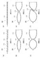
- FIG. 4 is a cross-sectional view at each location in FIG.
- FIG. 4A is a cross-sectional view taken along the line AA in FIG.
- FIG. 4B cross-sectional view taken along line BB of FIG. 3B
- Chamber 114 begins to expand.
- FIG. 4C C-C cross-sectional view in FIG. 3C.
- the main chamber 112 and the delay chamber 114 approach each other in the vehicle front-rear direction as the thickness increases in the vehicle width direction due to expansion.
- the delay chamber 114 relatively moves to the main chamber side (vehicle front-rear center side).
- FIGS. 4 (a) to 4 (c) illustrate the expansion / deployment process of the gas flow path portion corresponding to the series of FIGS. 4 (a) to 4 (c).
- FIG. 4D DD sectional view of FIG. 3A
- FIG. 4E EE sectional view of FIG. 3B
- the gas flows from the main chamber 112 to the delay chamber 114 through the gas inflow path 116.
- FIG. 4F a cross-sectional view taken along the line FF in FIG. 3C
- the main chamber 112 and the delay chamber 114 expand, the two chambers approach each other.
- a flange 136 is formed in the gas flow path 116.
- the peripheral edges of the chambers move to the central side as they expand.
- the delay chamber 114 and the main chamber 112 located on both sides of the gas flow path portion 116 are chambers having a large diameter extending from the upper edge 120 to the lower edge 122 of the airbag 100.
- the lower portions of the delay chamber 114 and the main chamber 112 move upward toward the respective central sides, that is, the central sides in the longitudinal direction of the airbag 100.
- the gas flow path part 116 is disposed along the lower edge 122 of the airbag 100 and is a small-diameter chamber in which a non-inflatable region such as the line seam part 118 is disposed above.
- the tension applied to the gas flow path portion 116 having a small diameter is very small compared to the delay chamber 114 and the main chamber 112 on both sides.
- the gas flow path part 116 is also easy to sag due to this difference in tension.
- the gas flow path portion 116 that has become easy to sag in this manner is crushed by the approach of the main chamber 112 and the delay chamber 114 on both sides as illustrated in FIG.
- the base fabric is folded and a collar 136 is formed.
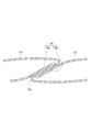
- FIG. 5 is an enlarged view illustrating the vicinity of the flange 136 in FIG.
- the formation of the flange 136 causes the base fabric 116a on the front side and the base fabric 116b on the back side of the gas flow path unit 116 to be folded.
- the base fabric 116a and the base fabric 116b are brought into close contact with each other, and the gas flow path portion 116 is closed.
- the outflow of gas from the delay chamber 114 to the main chamber 112 is inhibited, and the delay chamber 114 can receive the occupant while maintaining the internal pressure higher.
- the presence of the surface seam 124 illustrated in FIG. 3A is important. Due to the presence of the surface seam portion 124 having a predetermined range in the vehicle front-rear direction, the tension in the vehicle front-rear direction and upward is weakened or not applied to the base fabric of the gas inflow path 116 below the surface seam portion 124. As a result, and the main chamber 112 and the delay chamber 114 approach when the expansion and deployment are completed as shown in FIG. 3C, the base fabric of the gas inflow path 116 is slackened to form the flange 136.
- the flange 136 (see FIG. 3C) is formed between the lowermost point P1 of the substantially circular surface seam portion 124 and the lower edge 122.
- the vertical width W1 of the gas inflow path 116 is set to 70 mm between the surface seam portion 124 and the lower edge 122 (the airbag 100 at the same position).
- the vertical width W2 is about 550 mm).
- the substantially circular surface seam portion 124 the lower edge has an arc shape, and the flange portion 136 can be formed by being concentrated at one point P1 without being dispersed.
- a deeper flange portion as illustrated in FIG. 136 can be formed.
- the flange 136 it is possible to efficiently prevent the gas from flowing through the gas inflow passage 116 and maintain the internal pressure of the delay chamber 114 higher. In this way, the delay chamber 114 can exhibit a high vehicle outside emission prevention performance.
- the shape of the surface seam portion 124 is not limited to a circle, and an ellipse or a curved shape can be selected as appropriate as long as the lower edge is an arc shape.
- the length of the surface seam portion 124 along the gas flow path portion 116 was measured. It has been found that if the diameter is within a range of 150 mm to 5 mm, it is possible to close the gas flow path 116 by forming the flange 136. In particular, 80 mm or less is preferable, and the best results were obtained in the range of 70 mm to 30 mm. It has also been found that the flange 136 can be formed if the vertical width W1 of the gas flow path 116 is in the range of 150 mm to 10 mm. In particular, it is preferably 95 mm or less, and the best results were obtained at 90 to 50 mm.
- FIG. 6 is a diagram illustrating an out-of-vehicle emission prevention performance evaluation test for the curtain airbag according to the present embodiment.
- the impactor is defined in V. “Proposed Ejection Mitigation Requirements and Test Procedures” of NPRM (NHTSA-2009-0183).
- the impactor's collision target is NPRM (NHTSA-2009-0183)
- V. “Proposed Ejection Mitigation Requirements and Test Procedures” d. “Locations Where the Device would Impact the Ejection Mitigation Countermeasure To Toses Efficacy”, 4. for Determining Impactor Target Locations ”. Symbols A1 to A4 illustrated in FIG.
- collision targets of each target described in this NPRM (NHTSA-2009-0183). These collision targets are set for the side window 108 at the forefront of the vehicle.
- the delay chamber 114 is designed to cover the foremost collision target (hereinafter referred to as “A1 hit point”).
- a test device called an impactor (not shown) is caused to collide with each hit point from the inside of the vehicle, and the amount of movement of the impactor in the vehicle outward direction is measured.
- the measurement reference position of the moving amount at that time is a vertical plane that is in contact with a point on the outermost side of the impactor when the impactor is in contact with the inner surface of the side window 108.
- FIG. 7 shows the test results of the side impact test at the A1 hit point in FIG.
- the horizontal axis in FIG. 7 is the distance to the measurement reference position (thick line) described above, and the right side is the vehicle outer side and the left side is the vehicle inner side.
- the vertical axis represents the acceleration of the impactor, and represents the deceleration from that when the test start time is zero.
- the test result of the airbag 100 is represented by a solid line as an example.
- Comparative Example 1 is a simulation in a conventional configuration in which the flange 136 is not formed
- Comparative Example 2 is a simulation in a configuration in which only the delay chamber is provided without being connected to another chamber.
- FIG. 8 is a diagram illustrating a modification of the curtain airbag 100 of FIG.
- the airbag 200 in FIG. 8 is in an inflated and deployed state, and is different from the delay chamber 114 of the airbag 100 in the arrangement position of the delay chamber 214 in this state.
- the delay chamber 214 is arranged so that the upper part 216 overlaps the front pillar 107. Further, the lower part 218 of the delay chamber 214 overlaps the door trim 109 in the same manner as the airbag 100 (see FIG. 1B).
- the delay chamber 214 moves toward the outside of the vehicle by the contact of the impactor. At that time, the lower portion 218 interferes with the door trim 109, and the upper portion 216 interferes with the front pillar 107. As a result, movement toward the outside of the vehicle is suppressed. At this time, since the delay chamber 214 maintains the internal pressure high by the flange 132, it can be repelled suitably without breaking the posture or the expanded state of the front pillar or the like.
- the delay chamber 214 can exhibit high out-of-vehicle release prevention performance.
- the delay chamber 214 is set so that the outside discharge of the impactor is within 100 mm from the inner surface of the side window 108 in order to satisfy the regulations of NHTSA-2009-0183.
- the upper portion 216 of the delay chamber 214 may be set so that interference with the front pillar 107 can be maintained even when the impactor is moved 100 mm from the inner surface of the side window 108. As a result, it is possible to efficiently enhance the out-of-vehicle release prevention performance.
- the strap 126 has a length that does not cause tension when the airbag 100 is inflated and deployed so that the strap 126 does not hinder the formation of the collar 132. That is, the strap 126 is set to be somewhat long.
- the length of the strap 126 is such that the delay chamber 214 does not become tensioned until a predetermined position in the vehicle outer direction, specifically, until the impactor in contact with the delay chamber 214 moves 100 mm from the inner surface of the side window 108 to the vehicle outer side.
- the length is set.
- the original function of the strap 126 which prevents disorder of the deployment behavior of the airbag 100 can also be exhibited.
- the strap 126 is set so that the occupant can be received in a state where the delay chamber 214 maintains a high internal pressure by the flange 132.
- the strap 126 is provided at the attachment position P2 above the gas flow path 116 in the vertical direction of the airbag 100. Since the tension is not directly applied from the strap 126 to the gas flow path portion 116 at the attachment position P2, it is possible to prevent the formation of the flange 136 due to the tension.
- the attachment position P2 of the strap 126 is provided at a position above the center (M) in the vertical direction (H to L) on the edge portion 150 of the airbag 100 on the vehicle front side. In this way, in the present embodiment, consideration is given to the effect of stabilizing the deployment behavior by supporting the airbag 100 with a configuration that further suppresses the possibility of inhibiting the formation of the collar portion 136.
- the length of the strap 126 need not be such that it is not completely tensioned when the expansion is completed, and at least the length of the collar 132 that can narrow the gas flow path 116 can be formed. It is possible to improve the release prevention performance of the vehicle.
- the delay chamber 214 can exhibit a sufficient ability to prevent release outside the vehicle. Therefore, for example, it is possible to reduce the material cost by reducing the area where the lower portion 218 interferes with the door trim 109.
- the delay chambers 114 and 214 are disposed on the vehicle front side of the airbags 100 and 200.
- the delay chambers 114 and 214 such as the position of the rearmost chamber 140 illustrated in FIG. It is possible to arrange them at other positions as appropriate.
- the present invention can be used for a curtain airbag that inflates and deploys along a side surface of a vehicle interior for the purpose of protecting an occupant at the time of a vehicle side collision or rollover (rollover).
Landscapes
- Engineering & Computer Science (AREA)
- Mechanical Engineering (AREA)
- Physics & Mathematics (AREA)
- Fluid Mechanics (AREA)
- Air Bags (AREA)
Abstract
Description
102 …車両、
104 …インフレータ、
106 …ルーフサイドレール、
107 …フロントピラー、
108 …サイドウィンドウ、
109 …ドアトリム、
110 …前部座席、
112 …メインチャンバ、
114、214 …ディレーチャンバ、
116 …ガス流入路、
116a …ガス流入路の表側の基布、
116b …ガス流入路の裏側の基布、
118 …線シーム部、
120 …上縁、
122 …下縁、
124・224 …面シーム部、
126 …ストラップ、
128 …タブ、
130 …幅広部、
132 …最後部ウィンドウ、
134 …最後部座席、
136 …皺部、
140 …チャンバ、
150 …前縁、
216 …上部、
218 …下部
T=張力、P=内圧(各部位に共通)、r=各部位の半径
図6は、本実施形態にかかるカーテンエアバッグに対する車外放出防止性能評価試験を例示する図である。インパクタは、NPRM(NHTSA-2009-0183)のV. 「Proposed Ejection Mitigation Requirements and Test Procedures」で規定されている。インパクタの衝突目標は、同NPRM(NHTSA-2009-0183)のV. 「Proposed Ejection Mitigation Requirements and Test Procedures」、d.「Locations Where the Device Would Impact the Ejection Mitigation Countermeasure To Asses Efficacy」、4.「Method for Determining Impactor Target Locations」で定められるターゲットロケーション(Target locations)に規定されている。図6に例示する記号A1~A4は、このNPRM(NHTSA-2009-0183)に記載されている各ターゲットの打点(衝突目標)である。これらの衝突目標は、車両最前のサイドウィンドウ108に対して設定される。ディレーチャンバ114は、最も前方の衝突目標(以下「A1打点」と称する)を覆い得るように設計される。
図8は、図1(b)のカーテンエアバッグ100の変形例を表わす図である。図8のエアバッグ200は膨張展開した状態であって、この状態におけるディレーチャンバ214の配置位置においてエアバッグ100のディレーチャンバ114と異なっている。
Claims (10)
- 車両室内の側面部上方に収納され、該側面部に沿って膨張展開するカーテンエアバッグであって、
ガスが流入して膨張する袋状の膨張領域として、先に膨張するメインチャンバと、
前記メインチャンバからガスが流入して膨張するディレーチャンバと、
当該カーテンエアバッグの上縁から下縁の手前にかけて当該カーテンエアバッグの表裏の基布が線状に合わさって前記メインチャンバとディレーチャンバとを区画する線シーム部と、
前記線シーム部の下端に設けられ、前記表裏の基布を所定の範囲にわたって非膨張領域とした面シーム部と、
前記面シーム部から当該カーテンエアバッグの下縁までの間に設けられ、前記メインチャンバからディレーチャンバへガスを流入させるガス流入路とを備え、
当該カーテンエアバッグの膨張展開完了時において前記ガス流入路の表裏の基布がたるむことによって、該ガス流入路を塞ぐまたは狭隘にする皺部が形成されることを特徴とするカーテンエアバッグ。 - 前記皺部は、前記線シーム部および面シーム部を境界として膨張した前記メインチャンバとディレーチャンバとが互いに接近することによって前記ガス流入路に形成されることを特徴とする請求項1に記載のカーテンエアバッグ。
- 前記皺部は、前記面シーム部の最も下方の一点と前記下縁との間に形成されることを特徴とする請求項1または2に記載のカーテンエアバッグ。
- 前記面シーム部は、下縁が弧を描いていることを特徴とする請求項1から3のいずれか1項に記載のカーテンエアバッグ。
- 車両室内の側面部上方に収納され、該側面部に沿って膨張展開するカーテンエアバッグであって、
ガスが流入して膨張する袋状の膨張領域として、先に膨張するメインチャンバと、該メインチャンバからガスが流入して膨張するディレーチャンバと、
当該カーテンエアバッグの上縁から下縁の手前にかけて当該カーテンエアバッグの表裏の基布が線状に接合されて前記メインチャンバとディレーチャンバとを区画する線シーム部と、
前記線シーム部の下端に設けられ、前記表裏の基布を所定の範囲にわたって非膨張領域とした面シーム部と、
前記面シーム部から当該カーテンエアバッグの下縁までの間に当該カーテンエアバッグの下縁に沿うように設けられ、前記メインチャンバからディレーチャンバへガスを流入させるガス流入路とを備え、
前記ガス流路部には、当該カーテンエアバッグの膨張展開完了時において、表裏の基布が折り重なる皺部が形成されることを特徴とするカーテンエアバッグ。 - 前記皺部では、前記ガス流路部の表裏の基布が折り重なることで該表裏の基布が密着することを特徴とする請求項1から5のいずれか1項に記載のカーテンエアバッグ。
- 当該カーテンエアバッグの前後方向の端をピラーにつなぐストラップをさらに備え、
前記ストラップの長さは、当該カーテンエアバッグの膨張展開完了時に該ストラップが緊張しない長さであることを特徴とする請求項1から6のいずれか1項に記載のカーテンエアバッグ。 - 前記ストラップの長さはさらに、当該カーテンエアバッグが乗員を受け止めて車外の所定の位置に到達するまでは緊張しない長さであることを特徴とする請求項7に記載のカーテンエアバッグ。
- 前記ストラップは、当該カーテンエアバッグの上下方向において、前記ガス流路部よりも上方の位置に設けられることを特徴とする請求項7または8に記載のカーテンエアバッグ。
- 前記ストラップは、当該カーテンエアバッグの上下方向の中央よりも上方の位置に設けられることを特徴とする請求項1から8のいずれか1項に記載のカーテンエアバッグ。
Priority Applications (2)
| Application Number | Priority Date | Filing Date | Title |
|---|---|---|---|
| JP2013503523A JP5629368B2 (ja) | 2011-03-04 | 2012-03-02 | カーテンエアバッグ |
| US14/003,036 US8905432B2 (en) | 2011-03-04 | 2012-03-02 | Curtain airbag |
Applications Claiming Priority (2)
| Application Number | Priority Date | Filing Date | Title |
|---|---|---|---|
| JP2011048387 | 2011-03-04 | ||
| JP2011-048387 | 2011-03-04 |
Publications (1)
| Publication Number | Publication Date |
|---|---|
| WO2012121175A1 true WO2012121175A1 (ja) | 2012-09-13 |
Family
ID=46798139
Family Applications (1)
| Application Number | Title | Priority Date | Filing Date |
|---|---|---|---|
| PCT/JP2012/055471 Ceased WO2012121175A1 (ja) | 2011-03-04 | 2012-03-02 | カーテンエアバッグ |
Country Status (3)
| Country | Link |
|---|---|
| US (1) | US8905432B2 (ja) |
| JP (1) | JP5629368B2 (ja) |
| WO (1) | WO2012121175A1 (ja) |
Cited By (2)
| Publication number | Priority date | Publication date | Assignee | Title |
|---|---|---|---|---|
| WO2015045613A1 (ja) * | 2013-09-27 | 2015-04-02 | トヨタ自動車株式会社 | 車両用サイドエアバッグ装置及び車両用シート |
| EP3074280A4 (en) * | 2013-11-26 | 2017-07-12 | Autoliv ASP, Inc. | Wrap around side impact airbag systems and methods |
Families Citing this family (10)
| Publication number | Priority date | Publication date | Assignee | Title |
|---|---|---|---|---|
| US8851508B1 (en) | 2013-03-15 | 2014-10-07 | Autoliv Asp, Inc. | Delayed vent in airbag curtain |
| JP6225179B2 (ja) * | 2013-05-23 | 2017-11-01 | オートリブ ディベロップメント エービー | 車両用カーテンエアバッグ装置及びその取付構造 |
| US9573552B2 (en) * | 2013-06-19 | 2017-02-21 | Toyota Motor Engineering & Manufacturing North America, Inc. | Delay orifice opening |
| EP3105088B1 (en) * | 2014-02-11 | 2018-06-06 | Key Safety Systems, Inc. | Airbag cushion assembly with one-way check valves |
| JP6513937B2 (ja) * | 2014-11-20 | 2019-05-15 | 住商エアバッグ・システムズ株式会社 | エアバッグ |
| JP6825921B2 (ja) * | 2017-01-18 | 2021-02-03 | Joyson Safety Systems Japan株式会社 | カーテンエアバッグ、カーテンエアバッグ装置及びカーテンエアバッグ装置の製造方法 |
| US10906494B1 (en) * | 2017-01-19 | 2021-02-02 | State Farm Mutual Automobile Insurance Company | Systems and methods for predicting occupant location based on vehicular collision |
| US10836342B2 (en) * | 2017-10-31 | 2020-11-17 | Toyoda Gosei Co., Ltd. | Airbag for head protection |
| WO2022004814A1 (ja) * | 2020-07-03 | 2022-01-06 | オートリブ ディベロップメント エービー | 歩行者用エアバッグ装置 |
| JP7342825B2 (ja) * | 2020-09-16 | 2023-09-12 | 豊田合成株式会社 | 頭部保護エアバッグ装置 |
Citations (6)
| Publication number | Priority date | Publication date | Assignee | Title |
|---|---|---|---|---|
| JP2000335355A (ja) * | 1999-05-27 | 2000-12-05 | Takata Corp | 自動車乗員頭部の保護バッグ及び保護装置 |
| JP2006088844A (ja) * | 2004-09-22 | 2006-04-06 | Honda Motor Co Ltd | 車両用乗員保護装置 |
| JP2006306377A (ja) * | 2005-03-31 | 2006-11-09 | Nissan Motor Co Ltd | 車両横転時の乗員保護装置および乗員保護方法 |
| JP2007246086A (ja) * | 2006-03-14 | 2007-09-27 | Delphi Korea Corp | 車両用サイドエアバックの固定ブラケット |
| JP2008056242A (ja) * | 2002-02-27 | 2008-03-13 | Takata Corp | 頭部保護エアバッグ及び頭部保護エアバッグ装置 |
| JP2009227163A (ja) * | 2008-03-24 | 2009-10-08 | Toyoda Gosei Co Ltd | 頭部保護エアバッグ |
Family Cites Families (10)
| Publication number | Priority date | Publication date | Assignee | Title |
|---|---|---|---|---|
| US6213499B1 (en) * | 1998-08-03 | 2001-04-10 | Delphi Technologies, Inc. | Side air bag system |
| US6802530B2 (en) * | 2001-09-26 | 2004-10-12 | Key Safety Systems, Inc. | Rollover air bag with damping mechanism |
| JP4075463B2 (ja) | 2002-02-27 | 2008-04-16 | タカタ株式会社 | 頭部保護エアバッグ及び頭部保護エアバッグ装置 |
| WO2005039938A1 (ja) * | 2003-10-27 | 2005-05-06 | Autoliv Development Ab | サイドカーテンエアバッグ |
| JP2005178606A (ja) | 2003-12-19 | 2005-07-07 | Takata Corp | カーテンエアバッグ装置 |
| JP4449659B2 (ja) * | 2004-08-30 | 2010-04-14 | 日本プラスト株式会社 | 車両用カーテンエアバッグ |
| US7172212B2 (en) | 2004-09-22 | 2007-02-06 | Honda Motor Co., Ltd. | Vehicle occupant protection device |
| DE102005011641B4 (de) * | 2005-03-14 | 2017-04-06 | Trw Automotive Gmbh | Gassack |
| CN101743149B (zh) * | 2007-07-11 | 2015-05-06 | 旭化成工程株式会社 | 帘式安全囊 |
| JP5629325B2 (ja) * | 2010-09-13 | 2014-11-19 | オートリブ ディベロップメント エービー | カーテンエアバッグ |
-
2012
- 2012-03-02 US US14/003,036 patent/US8905432B2/en active Active
- 2012-03-02 WO PCT/JP2012/055471 patent/WO2012121175A1/ja not_active Ceased
- 2012-03-02 JP JP2013503523A patent/JP5629368B2/ja not_active Expired - Fee Related
Patent Citations (6)
| Publication number | Priority date | Publication date | Assignee | Title |
|---|---|---|---|---|
| JP2000335355A (ja) * | 1999-05-27 | 2000-12-05 | Takata Corp | 自動車乗員頭部の保護バッグ及び保護装置 |
| JP2008056242A (ja) * | 2002-02-27 | 2008-03-13 | Takata Corp | 頭部保護エアバッグ及び頭部保護エアバッグ装置 |
| JP2006088844A (ja) * | 2004-09-22 | 2006-04-06 | Honda Motor Co Ltd | 車両用乗員保護装置 |
| JP2006306377A (ja) * | 2005-03-31 | 2006-11-09 | Nissan Motor Co Ltd | 車両横転時の乗員保護装置および乗員保護方法 |
| JP2007246086A (ja) * | 2006-03-14 | 2007-09-27 | Delphi Korea Corp | 車両用サイドエアバックの固定ブラケット |
| JP2009227163A (ja) * | 2008-03-24 | 2009-10-08 | Toyoda Gosei Co Ltd | 頭部保護エアバッグ |
Cited By (3)
| Publication number | Priority date | Publication date | Assignee | Title |
|---|---|---|---|---|
| WO2015045613A1 (ja) * | 2013-09-27 | 2015-04-02 | トヨタ自動車株式会社 | 車両用サイドエアバッグ装置及び車両用シート |
| JP5804214B2 (ja) * | 2013-09-27 | 2015-11-04 | トヨタ自動車株式会社 | 車両用サイドエアバッグ装置及び車両用シート |
| EP3074280A4 (en) * | 2013-11-26 | 2017-07-12 | Autoliv ASP, Inc. | Wrap around side impact airbag systems and methods |
Also Published As
| Publication number | Publication date |
|---|---|
| US20130341894A1 (en) | 2013-12-26 |
| JP5629368B2 (ja) | 2014-11-19 |
| US8905432B2 (en) | 2014-12-09 |
| JPWO2012121175A1 (ja) | 2014-07-17 |
Similar Documents
| Publication | Publication Date | Title |
|---|---|---|
| JP5629368B2 (ja) | カーテンエアバッグ | |
| JP5529968B2 (ja) | カーテンエアバッグ | |
| JP5629325B2 (ja) | カーテンエアバッグ | |
| JP5901915B2 (ja) | カーテンエアバッグ | |
| JP6122185B2 (ja) | カーテンエアバッグ | |
| US10870407B2 (en) | Airbag apparatus for vehicle | |
| JP5856405B2 (ja) | カーテンエアバッグ | |
| JP5427220B2 (ja) | カーテンエアバッグ | |
| JP5623355B2 (ja) | カーテンエアバッグ | |
| JP2012046175A (ja) | カーテンエアバッグ | |
| JP5938176B2 (ja) | カーテンエアバッグ | |
| US12275368B2 (en) | Airbag device for pedestrian | |
| JP5646060B2 (ja) | カーテンエアバッグ | |
| JP5615791B2 (ja) | カーテンエアバッグ | |
| JP6072909B2 (ja) | カーテンエアバッグ装置 | |
| JP5623328B2 (ja) | カーテンエアバッグ | |
| JP5901909B2 (ja) | カーテンエアバッグ | |
| JP5947551B2 (ja) | カーテンエアバッグ | |
| JP5848101B2 (ja) | カーテンエアバッグ取付構造およびカーテンエアバッグ取付方法 | |
| JP2008056118A (ja) | 頭部保護エアバッグ装置 |
Legal Events
| Date | Code | Title | Description |
|---|---|---|---|
| 121 | Ep: the epo has been informed by wipo that ep was designated in this application |
Ref document number: 12755665 Country of ref document: EP Kind code of ref document: A1 |
|
| ENP | Entry into the national phase |
Ref document number: 2013503523 Country of ref document: JP Kind code of ref document: A |
|
| NENP | Non-entry into the national phase |
Ref country code: DE |
|
| WWE | Wipo information: entry into national phase |
Ref document number: 14003036 Country of ref document: US |
|
| 122 | Ep: pct application non-entry in european phase |
Ref document number: 12755665 Country of ref document: EP Kind code of ref document: A1 |