WO2012017479A1 - 空気調和機の室内機、及び空気調和機 - Google Patents
空気調和機の室内機、及び空気調和機 Download PDFInfo
- Publication number
- WO2012017479A1 WO2012017479A1 PCT/JP2010/004908 JP2010004908W WO2012017479A1 WO 2012017479 A1 WO2012017479 A1 WO 2012017479A1 JP 2010004908 W JP2010004908 W JP 2010004908W WO 2012017479 A1 WO2012017479 A1 WO 2012017479A1
- Authority
- WO
- WIPO (PCT)
- Prior art keywords
- heat exchanger
- fan
- indoor unit
- air
- side heat
- Prior art date
Links
Images


Classifications
-
- F—MECHANICAL ENGINEERING; LIGHTING; HEATING; WEAPONS; BLASTING
- F24—HEATING; RANGES; VENTILATING
- F24F—AIR-CONDITIONING; AIR-HUMIDIFICATION; VENTILATION; USE OF AIR CURRENTS FOR SCREENING
- F24F1/00—Room units for air-conditioning, e.g. separate or self-contained units or units receiving primary air from a central station
- F24F1/0007—Indoor units, e.g. fan coil units
- F24F1/0018—Indoor units, e.g. fan coil units characterised by fans
- F24F1/0029—Axial fans
-
- F—MECHANICAL ENGINEERING; LIGHTING; HEATING; WEAPONS; BLASTING
- F24—HEATING; RANGES; VENTILATING
- F24F—AIR-CONDITIONING; AIR-HUMIDIFICATION; VENTILATION; USE OF AIR CURRENTS FOR SCREENING
- F24F1/00—Room units for air-conditioning, e.g. separate or self-contained units or units receiving primary air from a central station
- F24F1/0007—Indoor units, e.g. fan coil units
- F24F1/0018—Indoor units, e.g. fan coil units characterised by fans
- F24F1/0033—Indoor units, e.g. fan coil units characterised by fans having two or more fans
-
- F—MECHANICAL ENGINEERING; LIGHTING; HEATING; WEAPONS; BLASTING
- F24—HEATING; RANGES; VENTILATING
- F24F—AIR-CONDITIONING; AIR-HUMIDIFICATION; VENTILATION; USE OF AIR CURRENTS FOR SCREENING
- F24F13/00—Details common to, or for air-conditioning, air-humidification, ventilation or use of air currents for screening
- F24F13/20—Casings or covers
-
- F—MECHANICAL ENGINEERING; LIGHTING; HEATING; WEAPONS; BLASTING
- F24—HEATING; RANGES; VENTILATING
- F24F—AIR-CONDITIONING; AIR-HUMIDIFICATION; VENTILATION; USE OF AIR CURRENTS FOR SCREENING
- F24F13/00—Details common to, or for air-conditioning, air-humidification, ventilation or use of air currents for screening
- F24F13/24—Means for preventing or suppressing noise
-
- F—MECHANICAL ENGINEERING; LIGHTING; HEATING; WEAPONS; BLASTING
- F24—HEATING; RANGES; VENTILATING
- F24F—AIR-CONDITIONING; AIR-HUMIDIFICATION; VENTILATION; USE OF AIR CURRENTS FOR SCREENING
- F24F13/00—Details common to, or for air-conditioning, air-humidification, ventilation or use of air currents for screening
- F24F13/20—Casings or covers
- F24F2013/205—Mounting a ventilator fan therein
-
- F—MECHANICAL ENGINEERING; LIGHTING; HEATING; WEAPONS; BLASTING
- F24—HEATING; RANGES; VENTILATING
- F24F—AIR-CONDITIONING; AIR-HUMIDIFICATION; VENTILATION; USE OF AIR CURRENTS FOR SCREENING
- F24F13/00—Details common to, or for air-conditioning, air-humidification, ventilation or use of air currents for screening
- F24F13/24—Means for preventing or suppressing noise
- F24F2013/242—Sound-absorbing material
-
- F—MECHANICAL ENGINEERING; LIGHTING; HEATING; WEAPONS; BLASTING
- F24—HEATING; RANGES; VENTILATING
- F24F—AIR-CONDITIONING; AIR-HUMIDIFICATION; VENTILATION; USE OF AIR CURRENTS FOR SCREENING
- F24F13/00—Details common to, or for air-conditioning, air-humidification, ventilation or use of air currents for screening
- F24F13/24—Means for preventing or suppressing noise
- F24F2013/247—Active noise-suppression
Definitions
- the present invention relates to an indoor unit in which a fan and a heat exchanger are housed in a casing, and an air conditioner including the indoor unit.
- an air conditioner in which a fan and a heat exchanger are housed in a casing.
- an air conditioner comprising a main body casing having an air inlet and an air outlet, and a heat exchanger disposed in the main body casing, wherein the air outlet includes a plurality of small propellers.
- an air conditioner in which a fan unit having a fan arranged in the width direction of the air outlet is disposed” (see, for example, Patent Document 1).
- This air conditioner is provided with a fan unit at the air outlet to facilitate airflow direction control, and a fan unit having the same configuration is also provided at the suction port to improve the heat exchanger performance due to an increase in the air volume. I am doing so.
- the air conditioner like patent document 1 is provided with the heat exchanger in the upstream of the fan unit (blower). Since the movable fan unit is provided on the air outlet side, the air flow changes due to the movement of the fan and the instability of the flow due to the asymmetric suction causes a decrease in the air volume and a reverse flow. Furthermore, the air whose flow is disturbed flows into the fan unit. Therefore, in an air conditioner like Patent Document 1, the flow of air flowing into the outer peripheral part of the wing part (propeller) of the fan unit whose flow rate is high is disturbed, and the fan unit itself becomes a noise source (noise deterioration).
- the present invention has been made to solve at least one of the above-described problems, and an object thereof is to obtain an indoor unit capable of suppressing noise and an air conditioner including the indoor unit.
- An indoor unit of an air conditioner according to the present invention includes a casing having a suction port formed in an upper portion thereof and a blower outlet formed in a lower side of a front surface portion, and an axial flow type or a slant provided on the downstream side of the suction port in the casing.
- a flow-type fan a heat exchanger that is provided downstream of the fan in the casing and upstream of the air outlet and that exchanges heat between the air blown from the fan and the refrigerant, and was sucked into the casing
- a filter that collects dust from the air, a fan motor to which a fan impeller is attached, or a fixing member to which a support structure that rotatably supports the fan impeller is fixed, and a rod-like shape that fixes the fixing member to the casing or
- a motor stay having a plate-like support member, and the filter and the motor stay are provided on the downstream side of the fan, and the motor stay includes the motor stay and the filter. It is arranged on the upstream side of the filter or arranged on the downstream side of the filter so that the distance is smaller than the maximum projected dimension that is the maximum among the projected dimensions of the cross section orthogonal to the longitudinal direction of the support member. .
- the indoor unit of the air conditioner according to the present invention includes a casing in which a suction port is formed in the upper part and a blower outlet is formed in the lower part of the front part, and an axial flow type provided on the downstream side of the suction port in the casing.
- a mixed flow type fan and a heat exchanger provided downstream of the fan in the casing and upstream of the air outlet, and for exchanging heat between the air blown from the fan and the refrigerant.
- an air conditioner according to the present invention is provided with the indoor unit described above.
- the filter and the motor stay are provided on the downstream side of the fan, and the motor stay is the maximum projection in which the distance between the motor stay and the filter is the maximum among the projected dimensions of the cross section perpendicular to the longitudinal direction of the support member. It is arranged on the upstream side of the filter so as to be smaller than the size, or is arranged on the downstream side of the filter. For this reason, the airflow in which the variation in the velocity distribution becomes small collides with the motor stay. Therefore, the fluctuation amount of the load applied to the motor stay is reduced, and noise generated from the motor stay can be suppressed.
- the fan housing is provided with a silencer mechanism. For this reason, the noise generated from the fan can be silenced by this silencing mechanism. Therefore, according to the present invention, an indoor unit that can suppress noise and an air conditioner including the indoor unit can be obtained.
- FIG. 10 It is a schematic block diagram which shows another example of the fan which concerns on Embodiment 10 of this invention. It is a principal part enlarged view (longitudinal sectional view) which shows an example of the convex part which concerns on Embodiment 10 of this invention. It is a principal part enlarged view (longitudinal sectional view) which shows another example of the convex part which concerns on Embodiment 10 of this invention. It is a principal part enlarged view (longitudinal sectional view) showing still another example of the convex portion according to Embodiment 10 of the present invention. It is explanatory drawing which shows an example of the airflow which generate
- Embodiment 14 of this invention It is a principal part enlarged view (longitudinal sectional view) showing an example of a fan according to Embodiment 13 of the present invention. It is a longitudinal cross-sectional view of the fan based on Embodiment 14 of this invention. It is front sectional drawing which shows another example of the fan which concerns on Embodiment 14 of this invention. It is a longitudinal cross-sectional view which shows another example of the fan which concerns on Embodiment 14 of this invention. It is front sectional drawing which shows another example of the fan which concerns on Embodiment 14 of this invention. It is a longitudinal cross-sectional view which shows the fan which concerns on Embodiment 15 of this invention.
- FIG. 30 It is a longitudinal cross-sectional view which shows the indoor unit which concerns on Embodiment 30 of this invention. It is a longitudinal cross-sectional view which shows the indoor unit which concerns on Embodiment 31 of this invention. It is a longitudinal cross-sectional view which shows the indoor unit which concerns on Embodiment 32 of this invention.
- 3 is a schematic diagram for explaining a configuration example of a heat exchanger 50.
- FIG. It is a longitudinal cross-sectional view which shows the indoor unit which concerns on Embodiment 33 of this invention.
- FIG. 77 is a left side view of the indoor unit shown in FIG. 76.
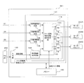
- Embodiment 35 of the present invention It is a front view of an indoor unit according to Embodiment 35 of the present invention. It is a block diagram which shows the control apparatus which concerns on Embodiment 35 of this invention. It is a front view which shows another example of the indoor unit which concerns on Embodiment 35 of this invention. It is a left view of the indoor unit shown in FIG. It is a front view which shows another example of the indoor unit which concerns on Embodiment 35 of this invention. It is a front view which shows the indoor unit which concerns on Embodiment 36 of this invention. It is a block diagram which shows the control apparatus which concerns on Embodiment 36 of this invention. It is a front view which shows the indoor unit which concerns on Embodiment 37 of this invention.
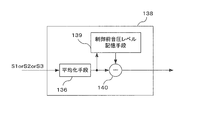
- FIG. 90 is a left side view of the indoor unit shown in FIG. 89. It is a front view which shows another example of the indoor unit which concerns on Embodiment 38 of this invention. It is a front view which shows the indoor unit which concerns on Embodiment 41 of this invention. It is a block diagram which shows the control apparatus which concerns on Embodiment 41 of this invention. It is a block diagram which shows the silence volume calculation means which concerns on Embodiment 41 of this invention. It is a front view which shows the indoor unit which concerns on Embodiment 42 of this invention.
- each unit constituting the indoor unit of the air conditioner will be described.
- the fifth and subsequent embodiments the detailed configuration of each unit or another example will be described.
- the present invention will be described by taking a wall-mounted indoor unit as an example.
- the shape and size of each unit (or a constituent member of each unit) may be partially different.
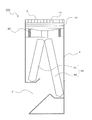
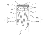
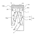
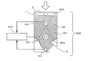
- FIG. 1 is a longitudinal sectional view showing an indoor unit (referred to as an indoor unit 100) of an air conditioner according to Embodiment 1 of the present invention.
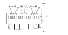
- FIG. 2 is an external perspective view showing the indoor unit.
- the left side in FIG. 1 will be described as the front side of the indoor unit 100.
- the configuration of the indoor unit 100 will be described with reference to FIGS. 1 and 2.
- the indoor unit 100 supplies conditioned air to an air-conditioning target area such as a room by using a refrigeration cycle that circulates a refrigerant.
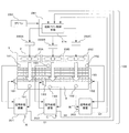
- the indoor unit 100 is mainly accommodated in a casing 1 in which a suction port 2 for sucking indoor air into the interior and a blower outlet 3 for supplying conditioned air to an air-conditioning target area are formed.
- the fan 20 sucks room air from the suction port 2 and blows out the conditioned air from the blower outlet 3 and the air passage from the fan 20 to the blower outlet 3, and exchanges heat between the refrigerant and the room air for conditioned air.
- a heat exchanger 50 for producing And the air path (arrow Z) is connected in the casing 1 by these components.
- the suction port 2 is formed in the upper part of the casing 1.
- the blower outlet 3 has an opening formed in the lower part of the casing 1 (more specifically, on the lower side of the front part of the casing 1).
- the fan 20 is disposed on the downstream side of the suction port 2 and on the upstream side of the heat exchanger 50, and is configured by, for example, an axial flow fan or a diagonal flow fan.
- the indoor unit 100 includes a control device 281 that controls the rotation speed of the fan 20 and the directions (angles) of the upper and lower vanes 70 and the left and right vanes 80 described later.
- the controller 281 may not be shown in the drawings shown in the first embodiment and each embodiment described later.
- the fan 20 is provided on the upstream side of the heat exchanger 50, so that it is compared with a conventional air conditioner indoor unit in which the fan 20 is provided at the outlet 3.
- the generation of the swirling flow of the air blown from the outlet 3 and the variation in the wind speed distribution can be suppressed. For this reason, comfortable ventilation to an air-conditioning object area is attained.
- there is no complicated structure such as a fan at the air outlet 3 it is easy to take measures against condensation that occurs at the boundary between warm air and cold air during cooling operation.
- the fan motor 30 is not exposed to cold air or warm air that is air-conditioned air, a long operating life can be provided.
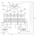
- the indoor unit 100 according to Embodiment 1 includes three fans 20 arranged in parallel along the longitudinal direction of the casing 1 (in other words, the longitudinal direction of the air outlet 3). Yes.
- approximately two to four fans 20 are preferable.
- all the fans 20 are configured in the same shape, and almost the same amount of air flow can be obtained by all the fans 20 by operating all the operation rotational speeds equally.
- the optimum fan design corresponding to the indoor unit 100 of various specifications can be achieved by combining the number, shape, size, and the like of the fans 20 according to the required air volume and the ventilation resistance inside the indoor unit 100. Is possible.
- a bell mouth 5 on a duct is disposed around the fan 20.
- the bell mouth 5 is for smoothly guiding the intake and exhaust of air to the fan.
- the bell mouth 5 according to the first embodiment has a substantially circular shape in plan view.
- the bell mouth 5 according to the first embodiment has the following shape.
- the upper part 5a has a substantially arc shape whose end part widens upward.
- the central portion 5b is a straight portion where the diameter of the bell mouth is constant.
- the lower part 5c has a substantially arc shape whose end part extends downward.
- the suction inlet 2 is formed in the edge part (arc part of the suction side) of the upper part 5a of the bellmouth 5.
- FIG. 1 of the first embodiment has a duct shape configured higher than the height of the impeller of the fan 20, but is not limited thereto, and the height of the bell mouth 5 is not limited thereto.
- a semi-open bellmouth configured lower than the height of the impeller of the fan 20 may be used.
- the bell mouth 5 may not be provided with the straight portion 5b shown in FIG. 1 but may be constituted only by the end portions 5a and 5c.
- the bell mouth 5 may be formed integrally with the casing 1, for example, in order to reduce the number of parts and improve the strength. Further, for example, the bell mouth 5, the fan 20, the fan motor 30, and the like may be modularized, and the casing 1 may be attached and detached to improve maintenance.
- the end of the upper portion 5a of the bell mouth 5 (arc portion on the suction side) is configured in a uniform shape with respect to the circumferential direction of the opening surface of the bell mouth 5.
- the bell mouth 5 has no structure such as a notch or a rib with respect to the rotation direction about the rotation axis 20a of the fan 20, and has a uniform shape having axial symmetry.
- the end of the upper portion 5a of the bell mouth 5 (the arc portion on the suction side) has a uniform shape with respect to the rotation of the fan 20.
- a uniform flow is realized as a flow. For this reason, the noise which generate
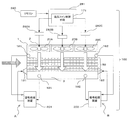
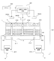
- partition plate 90 As shown in FIG. 2, in the indoor unit 100 according to the first embodiment, a partition plate 90 is provided between adjacent fans 20. These partition plates 90 are installed between the heat exchanger 50 and the fan 20. That is, the air path between the heat exchanger 50 and the fan 20 is divided into a plurality of air paths (three in the first embodiment). Since the partition plate 90 is installed between the heat exchanger 50 and the fan 20, the end on the side in contact with the heat exchanger 50 has a shape along the heat exchanger 50. More specifically, as shown in FIG. 1, the heat exchanger 50 includes a longitudinal section from the front side to the rear side of the indoor unit 100 (that is, a longitudinal section when the indoor unit 100 is viewed from the right side. Are arranged in a substantially ⁇ shape. For this reason, the heat exchanger 50 side end part of the partition plate 90 is also substantially [Lambda] type.
- the position of the end portion of the partition plate 90 on the fan 20 side may be determined as follows, for example.
- the end of the partition plate 90 on the fan 20 side may be extended to the outlet surface of the fan 20.
- the adjacent fans 20 are close enough to influence each other on the suction side, and the shape of the end of the upper portion 5a of the bell mouth 5 (arc portion on the suction side) can be formed sufficiently large.
- the end of the plate 90 on the fan 20 side extends to the upstream side (suction side) of the fan 20 so as not to affect the adjacent air path (so that the adjacent fans 20 do not affect each other on the suction side). It may be extended.
- the partition plate 90 can be formed of various materials.
- the partition plate 90 may be formed of a metal such as steel or aluminum.
- the partition plate 90 may be formed of resin or the like.
- the heat exchanger 50 becomes a high temperature during the heating operation, when the partition plate 90 is formed of a low melting point material such as a resin, the heat exchanger 50 is slightly between the partition plate 90 and the heat exchanger 50. A good space should be formed.
- the partition plate 90 is made of a material having a high melting point such as aluminum or steel, the partition plate 90 may be disposed in contact with the heat exchanger 50.
- the heat exchanger 50 is, for example, a fin tube type heat exchanger, a partition plate 90 may be inserted between the fins of the heat exchanger 50.
- the air path between the heat exchanger 50 and the fan 20 is divided into a plurality of air paths (three in the first embodiment).
- a noise absorbing material can be provided in this air passage, that is, in the partition plate 90 and the casing 1 to reduce noise generated in the duct.
- these divided air paths are formed in a substantially square shape with one side being L1 and L2 in a plan view. That is, the width of the divided air path is L1 and L2. For this reason, for example, the amount of air generated by the fan 20 installed inside the substantially square shape formed by L1 and L2 is reliably transferred to the heat exchanger 50 in the region surrounded by L1 and L2 downstream of the fan 20. pass.
- the air blown from each fan 20 is blown into the indoor unit 100 even if the flow field created downstream by the fan 20 has a swirling component. Cannot move freely in the longitudinal direction (the direction perpendicular to the plane of FIG. 1). For this reason, the air blown out by the fan 20 can be passed through the heat exchanger 50 in the region surrounded by L1 and L2 downstream of the fan 20. As a result, variation in the air volume distribution in the longitudinal direction of the indoor unit 100 flowing into the entire heat exchanger 50 (in the direction orthogonal to the plane of FIG. 1) can be suppressed, and high heat exchange performance can be achieved.
- each partition plate 90 does not need to be formed with a single plate, and may be formed with a plurality of plates.
- the partition plate 90 may be divided into two parts on the front side heat exchanger 51 side and the back side heat exchanger 55 side. Needless to say, it is preferable that there is no gap at the joint between the plates constituting the partition plate 90. By dividing the partition plate 90 into a plurality of parts, the assembling property of the partition plate 90 is improved.
- the fan 20 is rotationally driven by a fan motor 30.
- the fan motor 30 used may be an inner rotor type or an outer rotor type.
- the outer rotor type fan motor 30 a structure in which the rotor is integrated with the boss 21 of the fan 20 (the boss 21 is provided with a rotor) is also used. Further, by making the size of the fan motor 30 smaller than the size of the boss 21 of the fan 20, it is possible to prevent loss of the airflow generated by the fan 20. Further, by arranging a motor inside the boss 21, the axial dimension can be reduced. By making the fan motor 30 and the fan 20 easy to attach and detach, the maintainability is also improved.
- the use of a relatively expensive DC brushless motor as the fan motor 30 can improve efficiency, extend the service life, and improve the controllability. However, even if other types of motors are used, air conditioning It goes without saying that the primary function of the machine is satisfied. Further, the circuit for driving the fan motor 30 may be integrated with the fan motor 30 or may be configured externally to take dust and fire prevention measures.
- the fan motor 30 is attached to the casing 1 by a motor stay 16. Further, the fan motor 30 is a box type (fan 20, housing, fan motor 30, bell mouth 5, motor stay 16 and the like are integrated into a module) used for CPU cooling and the like, and is detachable from the casing 1. If the structure is possible, the maintainability is improved and the accuracy of the chip clearance of the fan 20 can be increased. In general, a narrow tip clearance is preferable because of high air blowing performance.
- the drive circuit of the fan motor 30 may be configured inside the fan motor 30 or may be outside.
- the motor stay 16 includes a fixing member 17 and a support member 18.
- the fixing member 17 is to which the fan motor 30 is attached.
- the support member 18 is a member for fixing the fixing member 17 to the casing 1.
- the support member 18 is, for example, a rod-like member, and extends from the outer peripheral portion of the fixing member 17, for example, radially. As shown in FIG. 1, the support member 18 according to the first embodiment extends approximately in the horizontal direction.
- the support member 18 may provide a stationary blade effect as a blade shape or a plate shape.
- the heat exchanger 50 of the indoor unit 100 according to Embodiment 1 is arranged on the leeward side of the fan 20.
- the heat exchanger 50 for example, a fin tube heat exchanger or the like may be used.
- the heat exchanger 50 is divided by a symmetry line 50a in the right vertical section.
- the symmetry line 50a divides the installation range of the heat exchanger 50 in this cross section in the left-right direction at a substantially central portion. That is, the front side heat exchanger 51 is on the front side (left side in FIG. 1) with respect to the symmetry line 50a, and the rear side heat exchanger 55 is on the back side (right side in FIG. 1) with respect to the symmetry line 50a.
- Each is arranged.
- the front-side heat exchanger 51 and the rear-side heat exchanger 55 are arranged so that the distance between the front-side heat exchanger 51 and the rear-side heat exchanger 55 widens with respect to the air flow direction, that is, the right-side longitudinal section.
- the heat exchanger 50 is arranged in the casing 1 so that the cross-sectional shape of the heat exchanger 50 is substantially ⁇ -shaped. That is, the front side heat exchanger 51 and the back side heat exchanger 55 are arranged so as to be inclined with respect to the flow direction of the air supplied from the fan 20.
- the heat exchanger 50 is characterized in that the air passage area of the rear heat exchanger 55 is larger than the air passage area of the front heat exchanger 51. That is, in the heat exchanger 50, the air volume of the back side heat exchanger 55 is larger than the air volume of the front side heat exchanger 51.
- the longitudinal length of the back side heat exchanger 55 is longer than the longitudinal length of the front side heat exchanger 51 in the right vertical section.
- the air path area of the back surface side heat exchanger 55 is larger than the air path area of the front surface side heat exchanger 51.
- the other configurations (such as the length in the depth direction in FIG. 1) of the front side heat exchanger 51 and the back side heat exchanger 55 are the same. That is, the heat transfer area of the back side heat exchanger 55 is larger than the heat transfer area of the front side heat exchanger 51.
- the rotating shaft 20a of the fan 20 is installed above the symmetry line 50a.
- the heat exchanger 50 By configuring the heat exchanger 50 in this manner, the generation of a swirling flow of the air blown from the blower outlet 3 and the distribution of the wind speed are compared with a conventional air conditioner indoor unit in which a fan is provided at the blower outlet. Occurrence can be suppressed.
- the air volume of the back side heat exchanger 55 is larger than the air volume of the front side heat exchanger 51. And when the air which passed each of the front side heat exchanger 51 and the back side heat exchanger 55 merges by this air volume difference, this merged air will bend to the front side (blower outlet 3 side). For this reason, it is no longer necessary to bend the airflow rapidly in the vicinity of the outlet 3, and the pressure loss in the vicinity of the outlet 3 can be reduced.
- the flow direction of the air flowing out from the back side heat exchanger 55 is the flow from the back side to the front side. For this reason, the indoor unit 100 according to the first embodiment bends the flow of air after passing through the heat exchanger 50, as compared with the case where the heat exchanger 50 is arranged in a substantially v shape in the right vertical section. It becomes easy.
- the indoor unit 100 has a plurality of fans 20 and thus tends to be heavy.
- the strength of the wall surface for installing the indoor unit 100 is required, which is a restriction on installation. For this reason, it is preferable to reduce the weight of the heat exchanger 50.
- positions the fan 20 in the upstream of the heat exchanger 50 the height dimension of the indoor unit 100 becomes large and tends to become restrictions on installation. For this reason, it is preferable to reduce the weight of the heat exchanger 50.
- a fin tube heat exchanger is used as the heat exchanger 50 (the front side heat exchanger 51 and the back side heat exchanger 55), and the heat exchanger 50 is downsized.
- the heat exchanger 50 according to the first embodiment includes a plurality of fins 56 stacked via a predetermined gap, and a plurality of heat transfer tubes 57 penetrating the fins 56.
- the fins 56 are stacked in the left-right direction of the casing 1 (the direction orthogonal to the plane of FIG. 1). That is, the heat transfer tube 57 passes through the fin 56 along the left-right direction of the casing 1 (the direction orthogonal to the plane of FIG. 1).
- Embodiment 1 in order to improve the heat exchange efficiency of the heat exchanger 50, two rows of heat transfer tubes 57 are arranged in the ventilation direction of the heat exchanger 50 (the width direction of the fins 56). These heat transfer tubes 57 are arranged in a substantially zigzag shape in the right vertical section.
- the heat transfer tube 57 is formed by a thin tube (diameter of about 3 mm to 7 mm) and the refrigerant flowing through the heat transfer tube 57 (the refrigerant used in the indoor unit 100 and the air conditioner equipped with the indoor unit 100) is R32.
- the heat exchanger 50 is reduced in size. That is, the heat exchanger 50 exchanges heat between the refrigerant flowing in the heat transfer tube 57 and the room air via the fins 56. For this reason, when the heat transfer tube 57 is made thin, the pressure loss of the refrigerant becomes large at the same refrigerant circulation amount as compared with a heat exchanger having a large heat transfer tube diameter.
- R32 has a larger latent heat of vaporization at the same temperature than R410A, and can exhibit the same ability with a smaller amount of refrigerant circulation. For this reason, by using R32, the amount of refrigerant to be used can be reduced, and the pressure loss in the heat exchanger 50 can be reduced. Therefore, the heat exchanger 50 can be reduced in size by configuring the heat transfer tube 57 as a thin circular tube and using R32 as the refrigerant.
- the heat exchanger 50 is reduced in weight by forming the fins 56 and the heat transfer tubes 57 from aluminum or an aluminum alloy.
- the weight of the heat exchanger 50 does not become an installation-like restriction
- the finger guard 15 and the filter 10 are provided at the suction port 2.
- the finger guard 15 is installed for the purpose of preventing the rotating fan 20 from being touched.
- the shape of the finger guard 15 is arbitrary as long as the hand cannot be touched to the fan 20.
- the shape of the finger guard 15 may be a lattice shape, or may be a circular shape formed of a large number of different rings.
- the finger guard 15 may be made of a material such as a resin or a metal material. However, when strength is required, the finger guard 15 is preferably made of a metal.
- the finger guard 15 is preferably as thin and strong as possible from the viewpoint of lowering ventilation resistance and maintaining strength.
- the filter 10 is provided to prevent dust from flowing into the indoor unit 100.
- the filter 10 is detachably provided on the casing 1.
- the indoor unit 100 which concerns on this Embodiment 1 may be provided with the automatic cleaning mechanism which cleans the filter 10 automatically.
- the indoor unit 100 which concerns on this Embodiment 1 is provided in the blower outlet 3 with the up-and-down vane 70 and the right-and-left vane (not shown) which are mechanisms which control the blowing direction of airflow.
- FIG. 3 is a perspective view of the indoor unit according to Embodiment 1 of the present invention as viewed from the front right side.
- FIG. 4 is a perspective view of the indoor unit as viewed from the rear right side.
- FIG. 5 is a perspective view of the indoor unit as viewed from the front left side.
- FIG. 6 is a perspective view showing the drain pan according to Embodiment 1 of the present invention.
- the right side of the indoor unit 100 is shown in cross section
- FIG. 5 the left side of the indoor unit 100 is shown in cross section.
- a front side drain pan 110 is provided below a lower end portion of the front side heat exchanger 51 (a front side end portion of the front side heat exchanger 51).
- a back side drain pan 115 is provided below the lower end portion of the back side heat exchanger 55 (the back side end of the back side heat exchanger 55).
- the back side drain pan 115 and the back portion 1b of the casing 1 are integrally formed.
- the back side drain pan 115 is provided with connection ports 116 to which the drain hose 117 is connected at both the left end and the right end. In addition, it is not necessary to connect the drain hose 117 to both the connection ports 116, and the drain hose 117 may be connected to one of the connection ports 116.
- the drain hose 117 when the drain hose 117 is to be pulled out to the right side of the indoor unit 100 during the installation work of the indoor unit 100, the drain hose 117 is connected to the connection port 116 provided at the right end of the back side drain pan 115, and the back side
- the connection port 116 provided at the left end of the drain pan 115 may be closed with a rubber cap or the like.
- the front side drain pan 110 is disposed at a position higher than the back side drain pan 115. Further, between the front side drain pan 110 and the back side drain pan 115, a drainage channel 111 serving as a drain moving path is provided at both the left end and the right end.
- the drainage channel 111 has a front end connected to the front drain pan 110 and is provided so as to incline downward from the front drain pan 110 toward the rear drain pan 115.
- a tongue portion 111 a is formed at the end of the drainage channel 111 on the back side. The rear end of the drainage channel 111 is disposed so as to cover the upper surface of the back side drain pan 115.
- the front-side drain pan 110 is provided at a position higher than the back-side drain pan 115, so that the drain collected by the front-side drain pan 110 is directed toward the back-side drain pan 115 toward the drainage channel 111. Flowing.
- the drain is dropped from the tongue 111 a of the drainage channel 111 to the back side drain pan 115 and collected by the back side drain pan 115.
- the drain collected by the back side drain pan 115 passes through the drain hose 117 and is discharged to the outside of the casing 1 (indoor unit 100).
- the drain collected by both drain pans is disposed on the back-side drain pan 115 (most rear side of the casing 1). Can be collected in the drain pan).
- the connection port 116 of the drain hose 117 in the back side drain pan 115 the drain collected by the front side drain pan 110 and the back side drain pan 115 can be discharged to the outside of the casing 1. Therefore, when performing maintenance (such as cleaning the heat exchanger 50) of the indoor unit 100 by opening the front surface of the casing 1, it is not necessary to attach or detach the drain pan to which the drain hose 117 is connected. Improves.
- the drainage channels 111 are provided at both the left end and the right end, even if the indoor unit 100 is installed in an inclined state, the drain collected by the front side drain pan 110 can be surely received from the back side drain pan. 115.
- the connection ports for connecting the drain hose 117 are provided at both the left end and the right end, the hose pull-out direction can be selected according to the installation conditions of the indoor unit 100, and the indoor unit 100 The workability when installing is improved.
- the drainage channel 111 is disposed so as to cover the backside drain pan 115 (that is, a connection mechanism is not required between the drainage channel 111 and the backside drain pan 115), the front side drain pan 110 is disposed. It becomes easy to attach and detach, and the maintainability is further improved.
- the drainage channel 111 may be disposed so that the rear side end of the drainage channel 111 is connected to the rear side drain pan 115 and the front side drain pan 110 covers the drainage channel 111. Even in such a configuration, it is possible to obtain the same effect as the configuration in which the drainage channel 111 is disposed so as to cover the back side drain pan 115. Further, the front-side drain pan 110 does not necessarily need to be higher than the rear-side drain pan 115. Even if the front-side drain pan 110 and the rear-side drain pan 115 have the same height, the drain collected by both drain pans is connected to the rear-side drain pan 115. The drainage hose can be discharged.
- the indoor unit 100 according to Embodiment 1 has an opening length d1 on the entrance side of the nozzle 6 in the right vertical section (between the drain pans defined between the front-side drain pan 110 and the back-side drain pan 115 portion.
- the throttle length d1) is configured to be larger than the opening length d2 on the outlet side of the nozzle 6 (the length of the outlet 3). That is, the nozzle 6 of the indoor unit 100 satisfies d1> d2 (see FIG. 1).
- d2 of the indoor unit 100 according to the first embodiment is approximately the same as the air outlet of the conventional indoor unit. It will be described as being length.
- the air passage becomes larger and the angle A of the heat exchanger 50 arranged on the upstream side (the front side heat on the downstream side of the heat exchanger 50). It is possible to increase the angle formed by the exchanger 51 and the back side heat exchanger 55. For this reason, the wind speed distribution generated in the heat exchanger 50 is relaxed, and the air path downstream of the heat exchanger 50 can be formed large, so that the pressure loss of the entire indoor unit 100 can be reduced. Furthermore, the deviation of the wind speed distribution that has occurred near the inlet of the nozzle 6 can be made uniform by the effect of contraction and guided to the outlet 3.
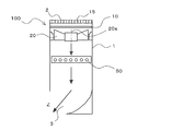
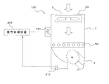
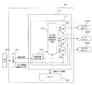
- the indoor unit 100 according to Embodiment 1 is provided with an active silencing mechanism as shown in FIG.
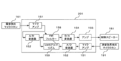
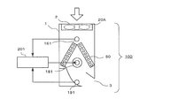
- the silencing mechanism of the indoor unit 100 includes a noise detection microphone 161, a control speaker 181, a silencing effect detection microphone 191, and a signal processing device 201.
- the noise detection microphone 161 is a noise detection device that detects the operation sound (noise) of the indoor unit 100 including the blowing sound of the fan 20.
- the noise detection microphone 161 is disposed between the fan 20 and the heat exchanger 50. In the first embodiment, it is provided on the front surface in the casing 1.
- the control speaker 181 is a control sound output device that outputs a control sound for noise.
- the control speaker 181 is disposed below the noise detection microphone 161 and above the heat exchanger 50.
- the silencing effect detection microphone 191 is a silencing effect detection device that detects the silencing effect by the control sound.
- the muffler effect detection microphone 191 is provided in the vicinity of the air outlet 3 in order to detect noise coming from the air outlet 3. Further, the muffler effect detection microphone 191 is attached at a position avoiding the wind flow so as not to hit the blown air coming out of the blowout port 3.
- the signal processing device 201 is a control sound generation device that causes the control speaker 181 to output a control sound based on the detection results of the noise detection microphone 161 and the silencing effect detection microphone 191.
- the signal processing device 201 is accommodated in the control device 281, for example.
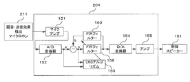
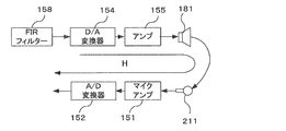
- FIG. 8 is a block diagram showing the signal processing apparatus according to Embodiment 1 of the present invention.
- Electric signals input from the noise detection microphone 161 and the muffler effect detection microphone 191 are amplified by the microphone amplifier 151 and converted from an analog signal to a digital signal by the A / D converter 152.
- the converted digital signal is input to the FIR filter 158 and the LMS algorithm 159.
- the FIR filter 158 generates a control signal that has been corrected so that the noise detected by the noise detection microphone 161 has the same amplitude and opposite phase as the noise when the noise reduction effect detection microphone 191 is installed.
- the indoor unit 100 is provided with a water receptacle or the like (not shown) for preventing water droplets from coming out of the air outlet 3 in the vicinity of the air outlet 3.
- a water receptacle or the like not shown
- positioned is upstream of the area
- the operation sound (noise) including the blowing sound of the fan 20 in the indoor unit 100 is detected by the noise detection microphone 161 attached between the fan 20 and the heat exchanger 50, and the microphone amplifier 151 and the A / D converter 152 are detected. And is input to the FIR filter 158 and the LMS algorithm 159.
- the tap coefficients of the FIR filter 158 are sequentially updated by the LMS algorithm 159.
- the coefficient is updated.
- h is a filter tap coefficient
- e is an error signal
- x is a filter input signal
- ⁇ is a step size parameter.
- the step size parameter ⁇ controls a filter coefficient update amount for each sampling.
- the digital signal that has passed through the FIR filter 158 whose tap coefficient has been updated by the LMS algorithm 159 is converted to an analog signal by the D / A converter 154, amplified by the amplifier 155, and the fan 20 and heat exchanger. 50 is emitted as a control sound from the control speaker 181 attached between the indoor unit 100 and the air passage in the indoor unit 100.
- the sound is transmitted from the fan 20 through the air path to the muffler effect detection microphone 191 attached in the direction of the outer wall of the air outlet 3 so that the wind emitted from the air outlet 3 does not hit.
- the sound after the control sound emitted from the control speaker 181 interferes with the noise coming out from the blow outlet 3 is detected. Since the sound detected by the muffling effect detection microphone 191 is input to the error signal of the LMS algorithm 159 described above, the tap coefficient of the FIR filter 158 is updated so that the sound after the interference approaches zero. become. As a result, noise in the vicinity of the air outlet 3 can be suppressed by the control sound that has passed through the FIR filter 158.
- the noise detection microphone 161 and the control speaker 181 are arranged between the fan 20 and the heat exchanger 50, and the silencing effect detection microphone 191 is connected to the blower outlet 3. It is installed in the place where the wind current does not hit. For this reason, since it is not necessary to attach a member that requires active silencing to the region B where condensation occurs, water droplets are prevented from adhering to the control speaker 181, the noise detecting microphone 161, and the silencing effect detecting microphone 191, and the silencing performance is deteriorated. The failure of the speaker and microphone can be prevented.
- the mounting positions of the noise detection microphone 161, the control speaker 181 and the mute effect detection microphone 191 shown in the first embodiment are merely examples.
- the noise reduction effect detection microphone 191 may be disposed between the fan 20 and the heat exchanger 50 together with the noise detection microphone 161 and the control speaker 181.
- the microphone has been exemplified as a means for detecting the silencing effect after the noise is canceled by the noise or the control sound, it may be configured by an acceleration sensor or the like that detects the vibration of the casing.
- the sound may be regarded as air flow disturbance, and the noise reduction effect after the noise is canceled by noise or control sound may be detected as air flow disturbance.
- a flow rate sensor, a hot wire probe, or the like that detects an air flow may be used as a means for detecting a silencing effect after noise is canceled by noise or control sound. It is also possible to detect the air flow by increasing the gain of the microphone.
- the FIR filter 158 and the LMS algorithm 159 are used in the signal processing device 201.
- any adaptive signal processing circuit that brings the sound detected by the mute effect detection microphone 191 close to zero may be active.
- a filtered-X algorithm that is generally used in the dynamic silencing method may be used.
- the signal processing device 201 may be configured to generate the control sound by a fixed tap coefficient instead of the adaptive signal processing.
- the signal processing device 201 may be an analog signal processing circuit instead of digital signal processing.
- the present invention is applicable even when the heat exchanger 50 that does not cause condensation is disposed. Therefore, it is possible to prevent performance deterioration of the noise detection microphone 161, the control speaker 181, the silencing effect detection microphone 191, and the like without considering the presence or absence of dew condensation due to the heat exchanger 50.
- FIG. ⁇ Motor support structure> For example, noise can be suppressed by attaching the fan 20 to the casing 1 with the motor stay 16 as described below.
- the same functions and configurations as those in the first embodiment will be described using the same reference numerals.
- FIG. 10 is a longitudinal sectional view showing the indoor unit according to Embodiment 2 of the present invention.
- the indoor unit 100 according to the second embodiment includes a fan 20 in which a fan motor 30 is connected to a boss 21.
- the fan motor 30 is attached to the casing 1 by a motor stay 16.
- the motor stay 16 includes a fixing member 17 and a support member 18.
- the fixing member 17 is to which the fan motor 30 is attached.
- the support member 18 is a member for fixing the fixing member 17 to the casing 1.
- the support member 18 is, for example, a rod-like member, and extends from the outer peripheral portion of the fixing member 17, for example, radially.
- the filter 10 is provided on the downstream side of the fan 20.
- the motor stay 16 and the filter 10 are provided close to each other (for example, both are in contact with each other).
- the support member 18 may provide a stationary blade effect as a blade shape or a plate shape.
- the airflow discharged from the fan 20 has a velocity distribution.
- the airflow having this velocity distribution collides with a downstream structure (for example, the motor stay 16), so that noise synchronized with the product of the rotational speed of the fan 20 and the number of blades is generated.
- a member having ventilation resistance is installed downstream of the fan 20
- the filter 10 (a member having ventilation resistance) is installed downstream of the fan 20.
- a motor stay 16, which is a main structure of the noise generation source, is installed in the vicinity of the filter 10. For this reason, since the airflow with a reduced velocity distribution collides with the motor stay 16, the amount of fluctuation of the load applied to the motor stay 16 is reduced, and noise generated from the motor stay 16 can be suppressed.
- the motor stay 16 is installed in the vicinity of the filter 10” indicates the following state.
- a steep velocity deficit region region where the flow velocity is slow
- the length of the velocity deficit area in the airflow direction is approximately the same as the dimension of the motor stay 16 projected in the airflow direction. Since the velocity deficit region is a portion where the velocity change of the air current is remarkable, strong vortices and turbulence of the air current are generated in the velocity deficit region due to the shearing force due to the velocity difference of the air current. As the strong vortex and air current turbulence occur, the amount of noise generated increases.
- the wake (downstream airflow) of the fan 20 has a complex flow velocity distribution
- the direction of the airflow that collides with the motor stay 16 varies.
- the support member 18 of the motor stay 16 is cut along a cross section orthogonal to the longitudinal direction of the support member 18 and the maximum projection dimension is the maximum projection dimension among the projection dimensions of this cross section, This is substantially equal to the maximum projected dimension. That is, by making the distance between the motor stay 16 and the filter 10 smaller than the maximum projected dimension, it is possible to suppress the generation of noise due to the turbulence of the airflow that occurs in the velocity deficient region.
- the motor stay 16 is installed in the vicinity of the filter 10” means that the motor stay 16 is arranged so that the distance between the motor stay 16 and the filter 10 is smaller than the maximum projected dimension. This means that it is installed upstream of the filter 10.
- the filter 10 is provided below the motor stay 16 (that is, downstream), but the filter 10 may be provided above the motor stay 16 (that is, upstream) as shown in FIG.
- the filter 10 is provided above the motor stay 16, it is not necessary to provide the motor stay 16 and the filter 10 close to each other. Since the velocity distribution of the airflow that has passed through the filter is small, noise generated from the motor stay 16 can be suppressed as described above.
- a moving guide for the filter 10 may be formed in the motor stay 16. Furthermore, it is desirable that the distance between the filter 10 as the ventilation resistor and the fan 20 is at least 25% of the fan 20 diameter.
- the motor stay 16 into the following shape, noise generated from the motor stay 16 can be further suppressed.
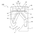
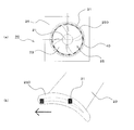
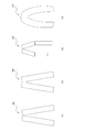
- FIG. 12 is a front view showing an example of a motor stay according to Embodiment 2 of the present invention (a plan view when the motor stay is attached to the indoor unit).
- the motor stay 16 shown in FIG. 12 has rod-shaped support members 18 extending radially from a substantially disk-shaped fixing member 17. These support members 18 have shapes that do not match the rear edge shape of the blades 23 of the fan 20.
- the support member 18 is formed in a curved shape, but the support member 18 may be formed in a linear shape. With this configuration, it is possible to prevent a large load from being applied to the support member 18 due to the overlapping of the rear edge portion of the blade 23 of the support member 18 and the fan 20, and further suppress noise generated from the motor stay 16. Can do.
- the number of support members 18 of the motor stay 16 and the number of blades 23 of the fan 20 may be in a prime relationship.
- the motor stay 16 By configuring the motor stay 16 in this way, it is possible to prevent the load on all the support members 18 from being in the maximum load state (the state in which the maximum load of the fluctuation amount of the load on the support member 18 is applied). The noise generated from the motor stay 16 can be further suppressed.
- the noise generated from the motor stay 16 can be further suppressed even if the motor stay 16 has a cross-sectional shape that is dull in the air flow direction, and does not easily induce air flow separation. Furthermore, by providing a soft hair material on the surface of the motor stay 16, it is possible to suppress pressure fluctuations on the surface of the motor stay 16, and to further reduce the generation of noise.
- the mounting structure of the fan motor 30 to the fixing member 17 is not particularly limited. As shown in FIG. 13, a fan motor 30 may be attached to the fixing member 17.
- FIGS. 13 to 16 are perspective views showing examples of mounting the fan motor to the fixing member of the motor stay according to Embodiment 2 of the present invention.
- FIG. 13 even if the fan motor 30 is fixed by providing the fixing member 17 with a through hole 17a penetrating in the vertical direction and screwing the fan motor 30 with a screw inserted into the through hole 17a. Good.
- the fan motor 30 is screwed, as shown in FIG. 14, the fan motor 30 is inserted into the fixing member 17 and the fan motor 30 is screwed by forming the through hole 17 a on the side surface of the fixing member 17. Good.
- the fixing member may be constituted by two fixing members 17b obtained by dividing the ring member.
- the fan motor 30 may be fixed to the fixing member 17 by sandwiching the fan motor 30 with the fixing members 17b and fixing the fixing members 17b to each other with screws.
- the strength of the shell portion having the weakest strength among the fan motors 30 can be improved. Since the shell portion having the weakest strength in the fan motor 30 is a portion that emits motor noise, the noise emitted from the fan motor 30 can be suppressed by improving the strength of the portion.
- the fan motor 30 may be fixed to the fixing member 17 by combining a plurality of fixing structures shown in FIGS. In FIG. 16, the fan motor 30 is fixed to the fixing member 17 by using two fixing structures shown in FIG. 15. By fixing the fan motor 30 at two points as described above, an effect of suppressing the swing of the fan motor 30 due to vibration or rotational imbalance can be obtained. Further, it goes without saying that a vibration isolator is provided on the fixing member 17 shown in FIGS. 13 to 16 to weaken the transmission of vibration to the casing 1.
- the indoor unit 100 including the fan 20 in which the fan motor 30 is connected to the boss 21 has been described.
- the indoor unit 100 provided with 20 may be sufficient.
- a support structure 35 (see FIG. 17 described later) that is rotatably attached to the boss 21 may be fixed to the fixing member of the motor stay 16.
- the motor stay 16 and the filter 10 may be integrally formed so that the motor stay 16 functions as a reinforcing member for the filter 10. Since the reinforcing member provided in the conventional filter is not necessary, the cost can be reduced by the amount of the reinforcing member.
- Embodiment 3 The motor stay 16 for attaching the fan 20 to the casing 1 may be configured as follows.
- items that are not particularly described are the same as those in the second embodiment, and the same functions and configurations are described using the same reference numerals.
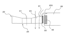
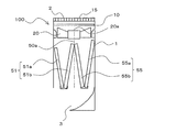
- FIG. 17 is a longitudinal sectional view showing the indoor unit according to Embodiment 3 of the present invention.
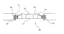
- FIG. 18 is an external perspective view showing the indoor unit. Note that FIG. 18 shows the casing 1 through. 17 and 18 include the indoor unit 100 including the fan 20 in which the fan motor 30 is provided between the blade 23 and the casing 26.
- the motor stay 16 according to the third embodiment is configured by a fixing member 17 provided along the longitudinal direction of the indoor unit 100. Both ends of the fixing member 17 in the longitudinal direction are fixed to the casing 1. And, to this fixing member 17, a support structure 35 (one that rotatably supports the boss 21 of the fan 20) of each of the three fans 20 is fixed. Further, the fixing member 17 is located above the transmutation portion of the heat exchanger 50 (the location where the arrangement gradient of the heat exchanger 50 is transformed, that is, the location where the front side heat exchanger 51 and the back side heat exchanger 55 are connected). Is provided. Although the motor stay 16 according to the third embodiment is configured not to include the support member 18, the fixing member 17 may be fixed to the casing 1 by the support member 18.
- Embodiment 4 FIG. Moreover, you may comprise the motor stay 16 which attaches the fan 20 to the casing 1 as follows.
- items that are not particularly described are the same as those in Embodiment 2 or Embodiment 3, and the same functions and configurations are described using the same reference numerals.
- FIG. 19 is a longitudinal sectional view showing an indoor unit according to Embodiment 4 of the present invention.
- the distance between the support member 18 and the rear edge of the blade 23 of the fan 20 is the tip of the blade 23 (the outer peripheral portion of the impeller 25) in a side view. It is configured to grow as you go.
- the airflow generated by the fan 20 increases toward the tip of the blade 23 (the outer peripheral portion of the impeller 25). That is, when the distance between the support member 18 and the trailing edge of the blade 23 is the same at the root portion and the tip portion of the blade 23, the load fluctuation amount related to the motor stay 16 is the tip portion of the blade 23 (the outer peripheral portion of the impeller 25). ) Grows toward However, in the fourth embodiment, the distance between the support member 18 and the rear edge of the blade 23 of the fan 20 is configured to increase toward the tip of the blade 23 (the outer peripheral portion of the impeller 25). Therefore, it is possible to suppress the load fluctuation amount related to the motor stay 16.
- the motor stay 16 having the configuration shown in the fourth embodiment, the motor stay 16 having a configuration in which the distance between the support member 18 and the rear edge of the blade 23 is the same at the root portion and the tip portion of the blade 23. As compared with the above, noise generated from the motor stay 16 can be further suppressed.
- Embodiment 5 FIG. ⁇ Fan & Fan Motor>
- an example of fan 20 provided in indoor unit 100 according to Embodiments 1 to 4 will be described.
- the fan 20 provided in the indoor unit 100 according to Embodiment 1 may be configured as follows, for example.
- the same functions and configurations as those of the first embodiment are described using the same reference numerals.
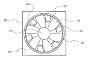
- FIG. 20 is a front view showing an example of a fan according to Embodiment 5 of the present invention.
- the fan 20 when the indoor unit 100 is planarly viewed in a state where the fan 20 is provided in the indoor unit 100 is a front view of the fan 20.
- the fan 20 according to the fifth embodiment is an axial fan, a diagonal fan, or the like in which a plurality of blades are provided on the outer peripheral surface of a boss that serves as a rotation center.
- the fan 20 includes an impeller 25 and a casing 26.
- the impeller 25 includes a boss 21 serving as a rotation center, a plurality of blades 23 (main blades) supported on the outer peripheral surface of the boss 21, and a ring-shaped member 22 provided on the outer peripheral side of the blade 23. Further, the impeller 25 according to the fifth embodiment includes a plurality of sub blades 24 supported by the ring-shaped member 22 toward the inner peripheral side (the boss 21 side). These sub blades 24 are not supported on the outer peripheral surface of the boss 21. As a result, the number of blades provided in the fan 20 (the number of blades 23 + the number of sub blades 24) is increased.
- a casing 26 is provided on the outer peripheral side of the impeller 25 through an outer peripheral portion of the impeller 25 and a predetermined gap. That is, the impeller 25 is housed in the housing 26.
- the boss 21 of the impeller 25 is connected to a fan motor 30 (not shown), and the impeller 25 rotates by the driving force of the fan motor.
- FIG. 21 is an explanatory diagram for explaining the relationship between the blade installation configuration (installation posture, number of installations, etc.) and aerodynamic performance.
- FIG. 21A is a front view showing a general impeller used for an axial flow fan and a mixed flow fan.
- FIG. 21B is a cross-sectional view of the blade row in which the cylindrical cross section at the position indicated by the alternate long and short dash line in FIG.
- the chord length L is a length of a straight line connecting the leading edge and the trailing edge of the blade 303.
- similar blade cascades having a constant chordal ratio ⁇ can obtain substantially the same aerodynamic performance. That is, it can be seen that in order to obtain the aerodynamic performance equal to that of a blade having a long chord length L with a blade having a short chord length L, the number of blades may be increased.
- the number of blades of the fan 20 (the impeller 25) is increased by the configuration shown in the fifth embodiment, it is not necessary to increase the number of blades supported by the boss 21.
- the sub blade 24 is connected to a portion other than the ring-shaped member 22, that is, the boss 21. For this reason, the chord length L can be shortened without reducing the air volume around the boss 21. Further, the blades 23 and the sub blades 24 do not need to change the angle of attack.
- the chord length L of the blade 23 in the range where the sub blade 24 is disposed can be shortened while maintaining the fan efficiency of the fan 20.
- the fan 20 can be reduced in thickness (reducing the dimension of the impeller 25 in the rotation axis direction) while maintaining fan efficiency.
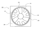
- FIG. 22 is a front view showing another example of a fan according to Embodiment 5 of the present invention.
- the fan 20 shown in FIG. 22 is provided with a protruding piece 23 a on the outer periphery of the blade 23.
- wing 24 is supported by this protrusion 23a toward the inner peripheral side (boss 21 side). That is, the fan 20 has a configuration in which the ring-shaped member 22 is divided into a plurality of parts.
- FIG. 23 is a front view showing still another example of the fan according to Embodiment 5 of the present invention.
- the fan 20 shown in FIGS. 20 and 22 was supported by members (ring-shaped member 22 and projecting piece 23a) provided on the blades 23.
- the sub blade 24 is directly supported by the blade 23.
- the sub blade 24 only needs to be supported by other than the boss 21. If the sub blade 24 is supported by other than the boss 21, the chord length L of the blade 23 in the range where the sub blade 24 is disposed can be shortened while maintaining the fan efficiency of the fan. For this reason, the fan 20 can be reduced in thickness (reducing the dimension of the impeller 25 in the rotation axis direction) while maintaining fan efficiency.
- Embodiment 6 FIG. As shown in the fifth embodiment, various configurations can be adopted as the configuration for supporting the sub blade 24. Among these, the structure which supports the sub blade
- items not particularly described are the same as those in the fifth embodiment, and the same functions and configurations are described using the same reference numerals.
- FIG. 24 is a longitudinal sectional view showing an example of a fan according to Embodiment 6 of the present invention.
- the sub blades 24 are supported by the ring-shaped member 22 similarly to the fan 20 shown in FIG. 20 of the fifth embodiment. That is, the outer peripheral part of each blade
- the centrifugal force acting on the blades 23 by the rotation of the impeller 25 is also supported by the ring-shaped member 22.
- wing 23 and a chord length can be made high.
- the shapes of the blades 23 and the sub blades 24 are different, but the shapes of the blades 23 and the sub blades 24 (more specifically, the shape excluding the joining portion) may be equal.
- Embodiment 7 the sub-blade 24 described in the fifth and sixth embodiments can be supported as follows.
- items not particularly described are the same as those in Embodiment 5 or Embodiment 6, and the same functions and configurations are described using the same reference numerals.
- FIG. 25 is a front view showing an example of a fan according to Embodiment 7 of the present invention.
- a ring-shaped member 23b is added to the fan 20 shown in FIG.
- the ring-shaped member 23b is provided so as to connect the substantially central portion of each blade 23.
- wing 24 is supported also by this ring-shaped member 23b in addition to the ring-shaped member 22 provided in the outer peripheral part of the blade
- the sub blade 24 can be supported at two locations, so that the vibration of the sub blade 24 can be suppressed and the strength of the sub blade 24 can be improved.
- FIG. 26 is a front view showing another example of a fan according to Embodiment 7 of the present invention.
- the fan 20 shown in FIG. 26 has a protruding piece 23c added to the fan 20 shown in FIG.
- the projecting piece 23 c is provided at a substantially central portion of each blade 23.
- wing 24 is supported also by this protrusion 23c in addition to the ring-shaped member 22 provided in the outer peripheral part of the blade
- the fan 20 shown in FIG. 22 may be provided with a ring-shaped member 23b and a protruding piece 23c, and the sub blade 24 may be supported at two locations.
- the fan 20 shown in FIG. 23 may be provided with the ring-shaped member 22 and the protruding piece 23a shown in the fifth embodiment and support the sub blades 24 at two locations.
- the sub blade 24 of the fan 20 shown in FIGS. 25 and 26 may be directly supported by the adjacent blade 23. By comprising in this way, the sub blade
- the sub blade 24 is supported at a plurality of locations. If the sub blade
- Embodiment 8 FIG.
- the number of blades 23 and sub blades 24 is the same, and they are alternately arranged in the rotation direction. Not only this but the blade
- items not particularly described are the same as those in the fifth to seventh embodiments, and the same functions and configurations are described using the same reference numerals.
- FIG. 27 is a front view showing an example of a fan according to Embodiment 8 of the present invention.
- the fan 20 shown in FIG. 27 has three sub blades 24 and six blades 23. When viewed in the rotational direction of the impeller 25, one sub blade 24 is provided after two blades 23 are provided. In the blades 23 and the sub blades 24, the interval between adjacent blades (interval in the circumferential direction) is substantially uniform.
- FIG. 28 is a front view showing another example of a fan according to Embodiment 8 of the present invention.
- the fan 20 shown in FIG. 28 has six sub blades 24, but three blades 23 are provided. When viewed in the rotational direction of the impeller 25, two sub blades 24 are provided after one blade 23 is provided. In the blades 23 and the sub blades 24, the interval between adjacent blades (interval in the circumferential direction) is substantially uniform.
- the number of the sub blades 24 is a divisor or a multiple of the number of the blades 23 and the interval (circumferential interval) between the blades 23 and the sub blades 24 is substantially uniform. It is possible to obtain an impeller capable of maintaining stable movement even during rotation and capable of stable operation.
- Embodiment 9 FIG.
- the externally driven fan motor 30 is connected to the boss 21 and the impeller 25 is rotated.
- the impeller 25 may be rotated by the fan motor 30 having the following configuration.
- items not particularly described are the same as those in the fifth to eighth embodiments, and the same functions and configurations are described using the same reference numerals.
- the fan motor 30 according to the ninth embodiment is adopted for the fan 20 shown in the sixth embodiment will be described.
- FIG. 29 is a longitudinal sectional view showing an example of a fan according to Embodiment 9 of the present invention.
- the fan 20 according to the ninth embodiment is different from the fan 20 shown in the sixth embodiment in the following points.
- the fan 20 according to the ninth embodiment is not provided with the externally driven fan motor 30 (the motor connected to the boss 21) provided in the fan 20 of the sixth embodiment.
- the externally driven fan motor 30 instead of the externally driven fan motor 30, a fan motor 30 including a rotor 31 and a stator 40 described later is provided.
- the rotor 31 is provided on the outer peripheral portion of the impeller 25. Since the fan 20 according to the ninth embodiment is provided with the ring-shaped member 22 on the outer peripheral portion thereof, the rotor 31 is provided on the outer peripheral portion of the ring-shaped member 22.
- the stator 40 is provided (disposed) in the casing 26 so as to face the rotor 31.
- the impeller 25 is rotated by the driving force of the fan motor 30 including the rotor 31 and the stator 40.
- the fan 20 configured as described above does not require a pace for installing an externally driven fan motor. For this reason, it becomes possible to make the fan 20 thinner.
- the fan motor 30 can be configured at a location having a large diameter, it is easy to generate a large torque even when the equivalent magnetic attractive force is generated (equal motor power consumption). For this reason, it is possible to increase the efficiency at the same cost, or it is possible to obtain a small and inexpensive fan 20 by making it possible to configure a motor having the same performance with an inexpensive magnet or armature.
- the example in which the fan motor 30 according to the ninth embodiment is adopted for the fan 20 according to the sixth embodiment has been described.
- the fifth embodiment, the seventh embodiment, and the eighth embodiment are described.
- the fan motor 30 according to the ninth embodiment may be adopted as the fan 20 according to the above.
- Embodiment 10 FIG.
- the fan 20 When the fan 20 is provided with the ring-shaped member 22 or the like, for example, the fan 20 may be configured as in the tenth embodiment.
- the same functions and configurations as those in the first to ninth embodiments will be described using the same reference numerals.
- FIG. 30 is a schematic configuration diagram showing an example of a fan according to Embodiment 10 of the present invention.
- 30A is a front view of the fan
- FIG. 30B is a side sectional view of the fan.
- a fan 20 shown in FIG. 30 is an axial fan, a diagonal fan, or the like in which a plurality of blades 23 are provided on the outer peripheral surface of a boss 21 that serves as a rotation center.
- the fan 20 includes an impeller 25 and a casing 26.
- the impeller 25 includes a boss 21, a plurality of blades 23 provided on the outer peripheral surface of the boss 21, and a rotor 31 provided on the outer peripheral side of the blade 23.
- the rotor 31 is configured by providing a ring-shaped member 22 or the like on the outer peripheral side of the blade 23 and forming the ring-shaped member 22 from a magnetic material.
- the rotor 31 is configured by providing a ring-shaped member 22 or the like on the outer peripheral side of the blade 23 and attaching or embedding a magnet on the outer peripheral side of the ring-shaped member 22.
- the impeller 25 is housed in a casing 26.
- the casing 26 is provided with a stator 40 on a surface (hereinafter referred to as an inner peripheral portion) facing the outer peripheral side of the impeller 25 (more specifically, the outer peripheral side of the rotor 31). That is, the rotor 31 and the stator 40 are disposed to face each other.
- the impeller 25 is rotated by the driving force of the fan motor 30 constituted by the rotor 31 and the stator 40.
- the fan 20 shown in FIG. 30 is an example of the fan shown in the tenth embodiment of the present invention.
- the fan according to the tenth embodiment may be the following fan, for example.
- FIG. 31 is a schematic configuration diagram showing another example of a fan according to Embodiment 10 of the present invention.
- FIG. 31 (a) is a front view of the fan
- FIG. 31 (b) is a perspective view showing the outer periphery of the fan blades.
- the arrow shown in FIG.31 (b) is a rotation direction of a blade
- the fan 20 shown in FIG. 31 is provided with a small blade 250 such as a winglet on the outer peripheral portion (outer peripheral end) of the blade 23.
- the rotor 31 is configured by forming the winglet 250 from a magnetic material. Further, for example, the rotor 31 is configured by attaching or embedding magnets on the outer peripheral side of the winglet 250.
- the fan 20 according to the tenth embodiment configured as described above is provided with a convex portion 251 in order to improve fan efficiency.
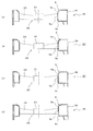
- FIG. 32 to FIG. 34 showing an installation example (formation example) of the convex portion 251, the fan 20 in which the ring-shaped member 22 is provided on the outer peripheral portion of the blade 23 will be described as an example.
- the convex portion 251 may be provided at a position on the air suction side.
- this convex part 251 may be provided in the outer peripheral part (for example, outer peripheral part of the ring-shaped member 22) of the impeller 25, as shown to Fig.32 (a).
- this convex part 251 may be provided in the inner peripheral part of the housing
- the convex portion 251 may be provided at a position on the air discharge side.
- this convex part 251 may be provided in the outer peripheral part (for example, outer peripheral part of the ring-shaped member 22) of the impeller 25, as shown to Fig.33 (a).
- this convex part 251 may be provided in the inner peripheral part of the housing
- 32 and 33 may be provided on both the outer peripheral portion of the impeller 25 (for example, the outer peripheral portion of the ring-shaped member 22) and the inner peripheral portion of the housing 26. That is, you may provide the convex part 251 provided in both so that it may mutually oppose.
- the convex portions 251 may be provided on both the air suction side and the air discharge side. Moreover, this convex part 251 may be provided in the outer peripheral part (for example, outer peripheral part of the ring-shaped member 22) of the impeller 25, as shown to Fig.34 (a). For example, this convex part 251 may be provided in the inner peripheral part of the housing
- the air suction side convex portion 251 may be provided on the outer peripheral portion of the impeller 25 (for example, the outer peripheral portion of the ring-shaped member 22), and the air discharge side convex portion 251 may be provided on the outer peripheral portion of the impeller 25.
- these formation positions may be reversed.
- the distance of the shortest portion between the impeller 25 and the housing 26 is made larger than the distance between the rotor 31 and the stator 40. Can be shortened. For this reason, the following effects can be acquired.
- the distance between the rotor and the stator is short (the gap formed between the rotor and the stator is preferably small).
- a conventional fan having a rotor on the outer periphery of the impeller and a stator on the housing side has a blade that is affected by the magnetic force generated between the rotor and the stator when the distance between the rotor and the stator is shortened.
- the car vibrates.
- noise is generated by this vibration. If the distance between the rotor and the stator is increased in order to prevent these vibrations and noises, an air flow that causes a decrease in fan efficiency is generated in the blade periphery.
- FIG. 35 is an explanatory diagram showing an example of an airflow that occurs in the periphery of the blades and causes a decrease in fan efficiency.
- the solid line arrow shown to Fig.35 (a) and FIG.35 (b) shows the flow direction of air.
- a white arrow shown in FIG. 35B indicates the rotation direction of the blade 303.
- the rotor and the stator When the distance between the two is increased, a leakage flow 253 as shown in FIG. 35B is generated, and the fan efficiency is lowered. More specifically, a leakage flow 253 is generated on the outer peripheral end side of the blade 303 from the high-pressure air discharge side to the low-pressure air suction side, and fan efficiency decreases.
- the fan 20 according to the tenth embodiment provides the convex portion 251 so that the distance of the shortest portion between the impeller 25 and the casing 26 is made larger than the distance between the rotor 31 and the stator 40. It is shortened. For this reason, the distance between the rotor 31 and the stator 40 can be a distance that can suppress the vibration of the impeller 25 and noise caused by the vibration. Moreover, the recirculation flow 252 and the leakage flow 253 can be suppressed by shortening the distance between the impeller 25 and the housing 26. That is, the fan 20 according to the tenth embodiment can increase the fan efficiency independently of the distance between the rotor 31 and the stator 40 which is a motor design matter.
- the sealing performance between the impeller 25 and the casing 26 is provided.
- the fan efficiency of the fan 20 can be further improved.
- the tip of the convex portion 251 shown in FIGS. 32 to 34 may have a labyrinth structure as shown in FIG.
- FIG. 36 shows a convex portion with a tip portion having a labyrinth structure as a convex portion 254.
- FIG. 36 shows an example in which the convex portion 254 is provided on the air discharge side of the impeller 25.
- the above-mentioned convex part 251 and convex part 254 may be provided continuously in the outer peripheral part of the impeller 25 and the inner peripheral part of the housing
- Embodiment 11 FIG. Even in the structure shown in the eleventh embodiment, the distance of the shortest portion between the impeller 25 and the casing 26 is shorter than the distance between the rotor 31 and the stator 40 as in the tenth embodiment. it can.
- items not particularly described are the same as those in the tenth embodiment, and the same functions and configurations are described using the same reference numerals.
- the ring-shaped member 22 and the small blades 250 are formed on the outer peripheral portion of the blade 23, and the rotor 31 is provided on the outer peripheral portion. That is, the basic configuration of the fan 20 is the same as the basic configuration of the fan 20 and the fan 20 according to the tenth embodiment.
- the fan 20 according to the eleventh embodiment replaces the convex portion 251 and the convex portion 254 shown in the tenth embodiment with at least one of the outer peripheral portion of the rotor 31 and the inner peripheral portion of the stator 40, such as resin.
- An insulating layer 257 is provided.
- the insulating layer 257 is provided as follows. The following FIG. 37 to FIG. 39 showing installation examples (formation examples) of the insulating layer 257 will be described by taking the fan 20 in which the ring-shaped member 22 is provided on the outer peripheral portion of the blade 23 as an example.
- the insulating layer 257 may be provided on the outer peripheral portion of the rotor 31.
- the insulating layer 257 may be provided on the inner peripheral portion of the stator 40.
- the insulating layer 257 may be provided on both the outer peripheral portion of the rotor 31 and the inner peripheral portion of the stator 40.
- the distance of the shortest portion between the impeller 25 and the casing 26 is set to be larger than the distance between the rotor 31 and the stator 40 as in the tenth embodiment. Can be shortened. For this reason, as in the tenth embodiment, the fan efficiency can be increased independently of the distance between the rotor 31 and the stator 40 which is a design matter of the motor.
- the distance of the shortest portion between the impeller 25 and the casing 26 is set to the rotor 31 without providing irregularities in the gap between the impeller 25 and the casing 26.
- the distance between the stator 40 and the stator 40 can be made shorter. For this reason, the assemblability at the time of manufacture improves and accumulation of dust etc. can be controlled.
- the insulating layer 257 on the inner peripheral portion of the stator 40 the coil wound around the stator 40 can be covered with the insulating layer 257 and the housing 26. By covering the uneven coil, accumulation of dust and the like can be further suppressed.
- Embodiment 12 FIG.
- the convex part provided in the outer peripheral part of the impeller 25 is good also as following structures. Note that in this twelfth embodiment, items that are not particularly described are the same as those in the tenth embodiment or the eleventh embodiment, and the same functions and configurations are described using the same reference numerals.
- FIG. 40 is an essential part enlarged view (longitudinal sectional view) showing an example of a fan according to Embodiment 12 of the present invention. Moreover, the solid line arrow shown in FIG. 40 shows the flow direction of air.
- an intake side guide 255 is provided on the intake side of the outer peripheral portion of the impeller 25.
- the intake side guide 255 is an example of a convex portion provided on the outer peripheral portion of the impeller 25, and is integrally formed with the ring-shaped member 22, for example.
- the front end portion of the intake side guide 255 has a shape protruding from the inner peripheral portion of the housing 26 to the outer peripheral side. Further, the intake side guide 255 has a shape whose diameter is increased toward the upstream side of the air flow. That is, the closest distance between the impeller 25 and the housing 26 is the distance in the rotation axis direction of the impeller 25. More specifically, the distance between the front end portion of the intake side guide 255 and the housing 26 is the closest distance between the impeller 25 and the housing 26. In FIG. 40, a stepped portion is formed in the casing 26 in a range facing the tip of the intake side guide 255.
- the distance of the shortest portion between the impeller 25 and the casing 26 is set between the rotor 31 and the stator 40 as in the tenth and eleventh embodiments. It can be shorter than the distance between. For this reason, as in the tenth and eleventh embodiments, the fan efficiency can be increased independently of the distance between the rotor 31 and the stator 40, which is a design matter of the motor.
- the airflow guided to the impeller 25 is smooth due to the shape of the intake side guide 255 whose diameter is increased toward the upstream side of the air flow. For this reason, the fan efficiency of the fan 20 is further improved.
- the fan 20 can be easily assembled even when the tip of the intake side guide 255 has a labyrinth structure. It becomes. Normally, when the impeller 25 is attached to the casing 26, the impeller 25 is inserted inside the casing 26 along the rotation axis direction of the impeller 25.
- Embodiment 13 The convex part provided in the outer peripheral part of the impeller 25 is good also as following structures.
- items that are not particularly described are the same as those in the tenth to twelfth embodiments, and the same functions and configurations are described using the same reference numerals.
- FIG. 41 is an enlarged view (longitudinal sectional view) showing a main part of an example of a fan according to Embodiment 13 of the present invention. Moreover, the solid line arrow shown in FIG. 41 shows the flow direction of air.
- a discharge-side guide 256 is provided on the discharge side of the outer peripheral portion of the impeller 25.
- the discharge side guide 256 is an example of a convex portion provided on the outer peripheral portion of the impeller 25, and is integrally formed with the ring-shaped member 22, for example.
- the distal end portion of the discharge side guide 256 has a shape protruding from the inner peripheral portion of the housing 26 to the outer peripheral side. Further, the discharge side guide 256 has a shape whose diameter is increased toward the downstream side of the air flow. That is, the closest distance between the impeller 25 and the housing 26 is the distance in the rotation axis direction of the impeller 25. More specifically, the distance between the distal end portion of the discharge side guide 256 and the housing 26 is the closest distance between the impeller 25 and the housing 26. In FIG. 41, a stepped portion is formed in the casing 26 in a range facing the tip end portion of the discharge side guide 256.
- the distance of the shortest portion between the impeller 25 and the casing 26 is set between the rotor 31 and the stator 40 as in the tenth to twelfth embodiments. It can be shorter than the distance between. For this reason, as in the tenth to twelfth embodiments, the fan efficiency can be increased independently of the distance between the rotor 31 and the stator 40, which is a design item of the motor.
- the air discharged from the impeller 25 decelerates while spreading in the radial direction due to the shape of the discharge-side guide 256 whose diameter is increased toward the downstream side of the air flow, Recover pressure. For this reason, the fan efficiency of the fan 20 is further improved.
- the fan efficiency of the fan 20 is further improved. Further, since the closest distance between the impeller 25 and the casing 26 is the distance in the rotation axis direction of the impeller 25, the fan 20 can be easily assembled even when the tip of the discharge side guide 256 has a labyrinth structure. It becomes. Normally, when the impeller 25 is attached to the casing 26, the impeller 25 is inserted inside the casing 26 along the rotation axis direction of the impeller 25.
- Embodiment 14 By causing the casing 26 of the fan 20 to function as a silencer mechanism, noise generated from the fan 20 can be reduced. In addition, by making the housing 26 of the fan 20 function as a silencer mechanism, it is possible to reduce noise generated from the motor stay. Therefore, the silencing effect of the indoor unit can be further improved by combining with the motor stay structure shown in the second to fourth embodiments. In the fourteenth embodiment, the same functions and configurations as those in the first to thirteenth embodiments are described using the same reference numerals.
- FIG. 42 is a longitudinal sectional view of a fan according to Embodiment 14 of the present invention.
- the casing 26 of the fan 20 according to the fourteenth embodiment is divided into an upper casing 26a and a lower casing 26b.
- the upper housing 26 a is composed of an upper surface portion of the housing 26, an upper portion 5 a of the bell mouth 5, and a central portion 5 b of the bell mouth 5.
- the lower housing 26 b includes an outer peripheral portion of the housing 26, a bottom surface portion of the housing 26, and a lower portion 5 c of the bell mouth 5.
- the inside of the housing 26 has a hollow structure.
- a gap having a length l is formed between the central portion 5b and the lower portion 5c of the bell mouth 5.
- This gap communicates with the inside of the housing 26, and is formed along the circumferential direction of the bell mouth 5, for example. That is, in the fourteenth embodiment, the gap having the length l has a slit shape.
- the fan 20 reduces the noise of the fan 20 (rotation sound of the impeller 25) by making the casing 26 have a hollow structure and functioning as a Helmholtz type silencer.
- f (a / 2 ⁇ ) ⁇ (A / l ⁇ V) 1/2 ... 2
- f noise frequency
- a sound velocity
- A gap area (that is, in the fourteenth embodiment, the length of the gap l ⁇ the circumferential length of the central portion 5b of the bell mouth 5)
- l the gap
- V the volume of the space in the housing 26.
- FIG. 43 is a front sectional view showing another example of a fan according to Embodiment 14 of the present invention.
- the inside of the housing 26 of the fan 20 is divided into a plurality of spaces (four spaces in FIG. 43) by the ribs 26c.
- V in the above equation 2 By varying the volume of these spaces (V in the above equation 2), it becomes possible to mute noises of more frequencies at the same time. It is also possible to adjust the frequency to be silenced by adjusting the length l of the gap communicating with each space shown in FIG.
- a gap (gap having a length l) communicating with the casing 26 is formed between the central part 5b and the lower part 5c of the bell mouth 5, but this gap (gap having a length l) is formed.
- a gap communicating with the housing 26 may be formed between the upper portion 5a and the central portion 5b of the bell mouth 5.
- the central portion 5b of the bell mouth 5 may be divided, and a gap (gap having a length l) communicating with the housing 26 may be formed between the divided central portions 5b.
- a plurality of gaps such as between the upper part 5a and the central part 5b of the bell mouth 5 and between the central part 5b and the lower part 5c of the bell mouth 5 may be formed.
- the housing 26 of the fan 20 in order for the housing 26 of the fan 20 to function as a Helmholtz-type silencer, it is only necessary to have a communication path communicating with the inside of the housing 26.
- the fan 20 may be configured as shown in FIG.
- FIG. 44 is a longitudinal sectional view showing still another example of a fan according to Embodiment 14 of the present invention.
- the fan 20 shown in FIG. 44 has a plurality of through-holes 5 d communicating with the internal space of the housing 26 formed in the central portion 5 b of the bell mouth 5, instead of the gap of length l communicating with the housing 26. .
- the housing 26 of the fan 20 can function as a Helmholtz-type silencer.
- the pressure fluctuation generated by the fan 20 can be reduced by forming the communication passage communicating with the inside of the housing 26 with a plurality of through holes, the noise generated from the fan 20 can be further reduced.
- the bell mouth 5 may be formed of a porous material.
- the space in the casing 26 may be divided by ribs 26c as shown in FIG. With this configuration, the volume of the space formed in the housing 26 can be increased, and noise in the low frequency region can be silenced.
- Embodiment 15 FIG.
- the fan 20 can be configured as in the fifteenth embodiment to improve the blowing performance of the fan 20.
- items not particularly described are the same as those in the fourteenth embodiment, and the same functions and configurations are described using the same reference numerals.
- FIG. 46 is a longitudinal sectional view showing a fan according to Embodiment 15 of the present invention.
- the fan 20 according to the fifteenth embodiment at least a part of the bell mouth 5 is integrally formed with the blade 23 of the impeller 25.
- wing 23 of the impeller 25 is not specifically limited.
- the central portion 5b of the bell mouth 5 and the blades 23 of the impeller 25 may be integrally formed.
- the upper portion 5a and the central portion 5b of the bell mouth 5 and the blades 23 of the impeller 25 may be integrally formed.
- FIG. 46A the central portion 5b of the bell mouth 5 and the blades 23 of the impeller 25 may be integrally formed.
- the upper portion 5a and the central portion 5b of the bell mouth 5 and the blades 23 of the impeller 25 may be integrally formed.
- the central portion 5b and the lower portion 5c of the bell mouth 5 and the blades 23 of the impeller 25 may be integrally formed. Further, for example, as shown in FIG. 46 (d), the entire bell mouth 5 (upper part 5a, central part 5b and lower part 5c) and the blades 23 of the impeller 25 may be integrally formed.
- the fan 20 By configuring the fan 20 in this way, it is possible to prevent leakage flow (flow from the blade pressure surface side to the blade suction surface side) generated in the gap between the blade 23 of the impeller 25 and the bell mouth 5. For this reason, the pressure difference of the suction inlet side and the blower outlet side of the fan 20 can be maintained, and the improvement of ventilation performance can be aimed at. Further, since noise generated from the fan 20 is reduced by preventing leakage flow and the like, in addition to the silencing effect obtained by causing the casing 26 of the fan 20 to function as a Helmholtz type silencer, a further silencing effect can be obtained. You can also.
- Embodiment 16 When the casing 26 of the fan 20 functions as a Helmholtz type silencer, the space in the casing 26 can be effectively used as follows.
- items that are not particularly described are the same as those in the fourteenth or fifteenth embodiment, and the same functions and configurations are described using the same reference numerals.
- FIG. 47 is a longitudinal sectional view showing a fan according to Embodiment 16 of the present invention.
- a circuit board 30a and a noise detection microphone 161 of a silencing mechanism are installed in a space inside the casing 26.
- the circuit board 30a is, for example, a circuit board on which a circuit for controlling the fan motor 30 and the like are mounted.
- the space efficiency inside the indoor unit 100 is improved, the indoor unit can be downsized and the air path loss can be reduced, and the power efficiency can be improved.
- casing 26 function as a Helmholtz type silencer, it is not necessary to provide the communication path connected to the space in the housing
- the noise detection microphone 161 detects the noise of the fan 20 transmitted through the housing 26, the noise generated by the fan 20 by the active silencing method described in the first embodiment can be reduced. In this case, it can be said that the housing 26 functions as a part of an active silencing mechanism.
- what is installed in the space inside the casing 26 is not limited to the circuit board 30a and the noise detection microphone 161, and may be a temperature measurement sensor, for example.
- Embodiment 17 when making the housing
- items not particularly described are the same as those in the fourteenth to sixteenth embodiments, and the same functions and configurations are described using the same reference numerals.
- FIG. 48 is a longitudinal sectional view showing a fan according to Embodiment 17 of the present invention.
- the fan 20 according to the seventeenth embodiment is provided with a sound absorbing material 260 in the space inside the housing 26.
- the sound absorbing material 260 is made of, for example, urethane, porous resin, porous aluminum, or the like.
- the pressure fluctuation generated by the fan 20 is absorbed by the sound absorbing material 260.
- the silencing effect obtained by causing the housing 26 of the fan 20 to function as a Helmholtz type silencer the silencing effect that the noise generated in the wide band by the sound absorbing material 260 can also be reduced is obtained.
- Embodiment 18 FIG. By providing fan 20 shown in Embodiments 5 to 17 in indoor unit 100 shown in Embodiment 1, the following effects can be obtained.
- FIG. 49 is a longitudinal sectional view showing an indoor unit according to Embodiment 18 of the present invention.
- FIG. 49 shows an example in which the fan 20 shown in any of the fifth to seventeenth embodiments is used in the indoor unit 100.
- 49 shows the left side of the drawing as the front side of the indoor unit 100.
- the fan 20 that can be downsized (thinned) and reduced in cost is used. For this reason, the indoor unit 100 according to Embodiment 18 can be reduced in size (thinned). In addition, the cost of the indoor unit 100 can be reduced. Moreover, in the indoor unit 100 configured as described above, the fan 20 is used which is reduced in size (thinned) while maintaining fan efficiency. For this reason, when an indoor unit of the same size is manufactured, an indoor unit having a larger air volume than a conventional indoor unit can be obtained.
- Embodiment 19 FIG. ⁇ Individual fan control>
- the indoor unit 100 according to the present invention includes the plurality of fans 20. By controlling each of these fans 20 individually, the wind direction controllability of the indoor unit 100 can be improved.
- the nineteenth embodiment an example of a specific embodiment for individually controlling the air volume of each fan 20 will be described.
- an indoor unit 100 in which three fans 20 are arranged side by side along the left-right direction (longitudinal direction) of the casing 1 will be described as an example.
- the fans 20 ⁇ / b> A, 20 ⁇ / b> B, and 20 ⁇ / b> C are referred to in order from the left side of the casing 1.
- the same reference numerals are used to describe the same functions and configurations as those in the first to eighteenth embodiments.
- the invention shown in the nineteenth embodiment is also established when the number of fans arranged in parallel in the indoor unit 100 is other than three.
- FIG. 50 is an explanatory diagram showing an example of the wind speed distribution at the air outlet in the indoor unit according to Embodiment 19 of the present invention.
- FIG. 50 shows a front view of the indoor unit 100.
- the indoor unit 100 according to Embodiment 19 is provided with three fans 20 in the left-right direction (longitudinal direction) of the casing 1.
- the wind speed distribution at the outlet 3 of the indoor unit 100 becomes as shown by the arrow in FIG. That is, assuming that the air volume of the fans 20A to 20C is fan 20A ⁇ fan 20B ⁇ fan 20C, the wind speed distribution at the outlet 3 of the indoor unit 100 is as shown by the arrow in FIG.
- the direction of the arrow shown in FIG. 50 shows the direction of airflow
- size of the arrow of FIG. 50 has shown the magnitude
- FIG. 51 is an explanatory diagram showing another example of the wind speed distribution at the air outlet in the indoor unit according to Embodiment 19 of the present invention.
- FIG. 51 shows a front view of the indoor unit 100.
- the wind speed distribution at the outlet 3 of the indoor unit 100 becomes as shown by the arrow in FIG. That is, if the air volume of the fans 20A to 20C is fan 20A> fan 20B> fan 20C, the wind speed distribution at the outlet 3 of the indoor unit 100 is as shown by the arrow in FIG.
- the direction of the arrow shown in FIG. 51 shows the direction of the air flow
- the size of the arrow in FIG. 51 shows the size of the wind speed. That is, the arrow in FIG. 51 indicates that the longer the length, the faster the wind speed (in other words, the greater the air volume).
- FIG. 52 is an essential part enlarged view (front sectional view) showing the vicinity of the air outlet of the indoor unit according to Embodiment 19 of the present invention.
- FIG. 52 shows the left and right vanes 80 when the airflow blown from the outlet 3 is controlled in the right direction of FIG.
- the airflow bent by the left and right vanes 80 collides with the side wall portion of the casing 1 in the vicinity of the air outlet 3, resulting in ventilation loss.
- the total air volume of the air outlet 3 is set to the same air volume as that of a conventional indoor unit (an indoor unit in which only one fan is provided or an indoor unit in which each of the plurality of fans is not controlled), By individually controlling the air volume of each fan 20, it is possible to reduce a ventilation loss caused by an air current colliding with the side wall portion of the casing 1.
- the difference of the air volume of the adjacent fans 20 is about 20% or less. It was found that there is little influence on the heat exchange performance. Further, it was found that if the difference in the air volume between adjacent fans 20 is about 10% or less, the influence on the heat exchange performance is further reduced. For this reason, when the air volume is individually controlled for each fan 20, the difference in the air volume between adjacent fans 20 is preferably about 20% or less. Further, when the air volume is individually controlled for each fan 20, it is more preferable that the difference in air volume between adjacent fans 20 is about 10% or less.
- the effect of individually controlling the air volume of each fan 20 is not limited to the above-described ventilation loss reduction effect.
- the air volume of each fan 20 may be individually controlled so that the airflow reaching this place increases.
- the airflow reaching this place increases.
- you want to avoid air-conditioning airflow when performing windbreak mild air-conditioning
- make sure that the airflow reaching this place is small (or that airflow does not reach this place) What is necessary is just to control the air volume of the fan 20 separately.
- a plurality of fans 20 having the same shape (same specifications) are provided, and the air volume of each fan 20 is individually controlled by changing the rotation speed of each fan 20.
- “the product of the number of blades 23 of the fan 20 and the number of rotations of the impeller 25 of the fan 20” may be separated by about 10 Hz for each fan 20.
- Embodiment 20 FIG. Further, the air volume of each fan 20 may be individually controlled as follows.
- items that are not particularly described are the same as those in the nineteenth embodiment, and the same functions and configurations are described using the same reference numerals.
- FIG. 53 is an explanatory diagram showing the wind speed distribution at the outlet when the air volume of each fan 20 is the same in the indoor unit according to Embodiment 20 of the present invention.
- FIG. 53 shows a front view of the indoor unit 100. 53 indicates the direction of airflow, and the size of the arrow in FIG. 53 indicates the size of the wind speed. That is, the arrow in FIG. 53 indicates that the longer the length, the faster the wind speed (in other words, the greater the air volume).
- FIG. 53 it can be seen that when the air volume generated by each fan 20 is the same, the wind speed decreases in the vicinity of both ends of the air outlet 3. This is because the wind speed is reduced by the airflow friction generated at the side wall of the casing 1 constituting the air passage.
- the indoor unit 100 when the indoor unit 100 is operated in the low air volume (low capacity) mode, the air volume of each fan 20 is controlled as shown in FIG.
- FIG. 54 is an explanatory diagram showing an example of the wind speed distribution at the outlet when the indoor unit according to Embodiment 20 of the present invention operates in the low air volume mode.
- the indoor unit 100 according to Embodiment 20 When operating in the low air volume (low capacity) mode, the indoor unit 100 according to Embodiment 20 has a fan 20A and a fan 20C arranged at both ends so that the wind speed in the vicinity of both ends of the air outlet 3 is increased. Is larger than the air volume of the fan 20B arranged in the center.
- the difference of the air volume of the adjacent fans 20 is about 20% or less. It was found that there is little influence on the heat exchange performance. Further, it was found that if the difference in the air volume between adjacent fans 20 is about 10% or less, the influence on the heat exchange performance is further reduced. For this reason, when the air volume is individually controlled for each fan 20, the difference in the air volume between adjacent fans 20 is preferably about 20% or less. Further, when the air volume is individually controlled for each fan 20, it is more preferable that the difference in air volume between adjacent fans 20 is about 10% or less.
- the air volume of each fan 20 is further individually increased so that the airflow reaching this place is increased. You may control to. Also, for example, if there is a place where you want to avoid air-conditioning airflow (when performing windbreak mild air-conditioning), make sure that the airflow reaching this place is small (or that airflow does not reach this place)
- the air volume of the fan 20 may be further individually controlled.
- each fan 20 The silencing effect is further improved by combining the configuration for individually controlling the air volume with these silencing mechanisms.
- an active silencing mechanism is provided in the indoor unit 100, it is preferable to provide a silencing mechanism according to the number of sound sources (the number of fans 20).
- a silencer mechanism corresponding to the number of sound sources cannot be provided due to restrictions on dimensions and costs of the indoor unit 100. Even in such a case, a sufficient silencing effect can be obtained by combining the configurations for individually controlling the air volume of each fan 20.
- FIG. 55 is a characteristic diagram showing the relationship between the air volume reduction rate of the central fan and the noise reduction effect at the same air volume in the indoor unit according to Embodiment 20 of the present invention.
- FIG. 55 shows the amount of noise reduction when the air volume of the fan 20B arranged in the center is reduced with the same total air volume of the air outlet 3. Further, -1 dB, -2 dB, -3 dB, -4 dB, and -5 dB shown in FIG. 55 are noise reduction effects with respect to noise that is most relevant to the sound detected by the noise reduction detection device.
- the noise detection microphone 161 and the control speaker of the silencing mechanism used to obtain the result of FIG.
- ⁇ 1 dB, ⁇ 2 dB, ⁇ 3 dB, ⁇ 4 dB, and ⁇ 5 dB shown in FIG. 55 indicate the silencing effect on the noise emitted by the fan 20A and the fan 20C.
- the entire indoor unit 100 can provide a silencing effect of 2.7 dB in total.
- the air volume of the central fan 20B is reduced by about 15% as shown in the present embodiment 20, in order to obtain the same air volume, the fan 20A and the fan 20B arranged in the vicinity of both ends are respectively Increase 7.5% airflow.
- the noise radiated by the fan 20A and the fan 20B disposed in the vicinity of both ends increases by 1.9 dB, and the noise radiated from the fan 20B disposed in the center is 2 dB reduction.
- the overall indoor unit 100 can obtain a noise reduction effect of 3.5 dB in total, and the noise reduction effect is improved as compared to before the air volume of each fan 20 is individually controlled.
- a plurality of fans 20 having the same shape (same specifications) are provided, and the air volume of each fan 20 is individually controlled by changing the rotation speed of each fan 20.
- “the product of the number of blades 23 of the fan 20 and the number of rotations of the impeller 25 of the fan 20” may be separated by about 10 Hz for each fan 20.
- Embodiment 21 FIG. Further, the air volume of each fan 20 may be individually controlled as follows.
- items that are not particularly described are the same as those in Embodiment 19 or Embodiment 20, and the same functions and configurations are described using the same reference numerals.
- FIG. 56 is an explanatory diagram showing an example of the wind speed distribution at the air outlet in the indoor unit according to Embodiment 21 of the present invention.
- FIG. 56 shows a front view of the indoor unit 100.
- 56 indicates the direction of airflow
- the size of the arrow in FIG. 56 indicates the size of the wind speed. That is, the arrow in FIG. 56 indicates that the longer the length, the faster the wind speed (in other words, the greater the air volume).
- the air volume of fan 20B arranged at the center is arranged at both ends so that the wind speed at the center of blower outlet 3 is larger than the wind speed near both ends. It is larger than the air volume of the fan 20A and the fan 20C.
- the airflow blown out from the air outlet 3 gradually loses velocity energy where it comes into contact with the low speed or stop air in the room, and finally the velocity at the center of the airflow is reduced.
- the air flow blown out from the air outlet 3 is made to be the same as that of the twenty-first embodiment, so that the flow velocity at the central portion of the air flow when the same air volume is generated is changed to the conventional indoor unit (the room provided with only one fan). Or an indoor unit that does not control the air volume of each of the plurality of fans), and airflow reachability can be improved.
- the difference of the air volume of the adjacent fans 20 is about 20% or less. It was found that there is little influence on the heat exchange performance. Further, it was found that if the difference in the air volume between adjacent fans 20 is about 10% or less, the influence on the heat exchange performance is further reduced. For this reason, when the air volume is individually controlled for each fan 20, the difference in the air volume between adjacent fans 20 is preferably about 20% or less. Further, when the air volume is individually controlled for each fan 20, it is more preferable that the difference in air volume between adjacent fans 20 is about 10% or less.
- the air volume of each fan 20 is further individually increased so that the airflow reaching this place is increased. You may control to. Also, for example, if there is a place where you want to avoid air-conditioning airflow (when performing windbreak mild air-conditioning), make sure that the airflow reaching this place is small (or that airflow does not reach this place)
- the air volume of the fan 20 may be further individually controlled.
- a plurality of fans 20 having the same shape (same specifications) are provided, and the air volume of each fan 20 is individually controlled by changing the rotation speed of each fan 20.
- “the product of the number of blades 23 of the fan 20 and the number of rotations of the impeller 25 of the fan 20” may be separated by about 10 Hz for each fan 20.
- Embodiment 22 FIG.
- a plurality of fans 20 having the same shape (same specifications) are provided, and the air volume of each fan 20 is individually controlled by changing the rotation speed of each fan 20.
- the present invention is not limited to this, and the same effects as those of the nineteenth to twenty-first embodiments can be obtained by using a fan 20 having a different blowing capacity (for example, a fan 20 having a different fan diameter, boss ratio, blade attachment angle, etc.).
- the use of a plurality of fans 20 with different blowing capacities improves the mounting density of the fans 20 and allows more detailed control of the wind speed distribution inside the indoor unit 100 (casing 1). The effect which was not acquired can also be acquired further.
- the difference in air volume between adjacent fans 20 is about 20% or less (more preferably 10% or less) to prevent the heat exchange performance from deteriorating, and “the number of blades 23 of the fan 20 and the impeller of the fan 20 It is effective to use the fans 20 having different numbers of blades 23 in order to achieve both of preventing the beat noise by separating the product of the rotational speed of 25 by about 10 Hz in each fan 20.
- Embodiment 23 FIG. ⁇ Heat exchanger>
- the fan 20 is disposed on the upstream side of the heat exchanger 50.
- production of a wind speed are suppressed compared with the indoor unit of the conventional air conditioner in which the fan is provided in the blower outlet. Therefore, the shape of the heat exchanger 50 is not limited to the shape shown in the first embodiment, and may be the following shape, for example.
- the same functions and configurations as those in the first to twenty-second embodiments are described using the same reference numerals.
- FIG. 57 is a longitudinal sectional view showing an indoor unit according to Embodiment 23 of the present invention.
- a heat exchanger 50 that is not divided into the front-side heat exchanger 51 and the rear-side heat exchanger 55 is provided on the downstream side of the fan 20.
- the air that has passed through the filter 10 flows into the fan 20.
- the air flowing into the fan 20 is less disturbed than the air flowing into the conventional indoor unit (passed through the heat exchanger).
- the indoor unit 100 according to Embodiment 23 can suppress noise as compared with the conventional indoor unit.
- the fan 20 is provided in the upstream of the heat exchanger 50, the indoor unit 100 is blown out from the blower outlet 3, compared with the indoor unit of the conventional air conditioner in which the fan is provided in the blower outlet.
- the generation of the swirling air flow and the generation of the wind speed distribution can be suppressed.
- there is no complicated structure such as a fan at the air outlet 3 it is easy to take measures against dew condensation caused by backflow or the like.
- Embodiment 24 By configuring the heat exchanger 50 with the front side heat exchanger 51 and the back side heat exchanger 55, it becomes possible to further suppress noise than the indoor unit 100 according to the twenty-third embodiment.
- the shape is not limited to the shape of the heat exchanger 50 shown in the first embodiment, and for example, the shape can be as follows.
- the twenty-fourth embodiment differences from the above-described twenty-third embodiment will be mainly described, and the same parts as those in the twenty-third embodiment are denoted by the same reference numerals.
- FIG. 58 is a longitudinal sectional view showing the indoor unit according to Embodiment 24 of the present invention.
- the front-side heat exchanger 51 and the back-side heat exchanger 55 constituting the heat exchanger 50 are separated by a symmetric line 50a in the right vertical section.
- the symmetry line 50a divides the installation range of the heat exchanger 50 in this cross section in the left-right direction at a substantially central portion. That is, the front side heat exchanger 51 is arranged on the front side (left side of the drawing) with respect to the symmetry line 50a, and the rear side heat exchanger 55 is arranged on the back side (right side of the drawing) with respect to the symmetry line 50a.
- the front-side heat exchanger 51 and the rear-side heat exchanger 55 are arranged so that the distance between the front-side heat exchanger 51 and the rear-side heat exchanger 55 is narrow with respect to the air flow direction, that is, the right-side longitudinal section. It is arrange
- the front side heat exchanger 51 and the back side heat exchanger 55 are arranged so as to be inclined with respect to the flow direction of the air supplied from the fan 20. Furthermore, the air path area of the back surface side heat exchanger 55 is characterized by being larger than the air path area of the front surface side heat exchanger 51.
- the longitudinal length of the back side heat exchanger 55 is longer than the longitudinal direction length of the front side heat exchanger 51 in the right vertical section. Thereby, the air path area of the back surface side heat exchanger 55 is larger than the air path area of the front surface side heat exchanger 51.
- the other configurations of the front side heat exchanger 51 and the back side heat exchanger 55 are the same. That is, the heat transfer area of the back side heat exchanger 55 is larger than the heat transfer area of the front side heat exchanger 51.
- the rotating shaft 20a of the fan 20 is installed above the symmetry line 50a.
- the fan 20 is provided on the upstream side of the heat exchanger 50, the same effect as in the twenty-third embodiment can be obtained.
- an amount of air according to the air passage area passes through each of the front side heat exchanger 51 and the back side heat exchanger 55. That is, the air volume of the back side heat exchanger 55 is larger than the air volume of the front side heat exchanger 51. And when the air which passed each of the front side heat exchanger 51 and the back side heat exchanger 55 merges by this air volume difference, this merged air will bend to the front side (blower outlet 3 side).
- the indoor unit 100 according to Embodiment 24 can further suppress noise compared to the indoor unit 100 according to Embodiment 23. Moreover, since the indoor unit 100 which concerns on this Embodiment 24 can reduce the pressure loss in the blower outlet 3 vicinity, it also becomes possible to reduce power consumption.
- the heat exchanger 50 shown in FIG. 58 is comprised by the substantially V shape by the front side heat exchanger 51 and the back side heat exchanger 55 which were formed separately, it is not limited to this structure.
- the front-side heat exchanger 51 and the back-side heat exchanger 55 may be configured as an integrated heat exchanger (see FIG. 67).
- each of the front side heat exchanger 51 and the back side heat exchanger 55 may be configured by a combination of a plurality of heat exchangers (see FIG. 67).
- the front side becomes the front side heat exchanger 51 and the rear side becomes the back side heat exchanger 55 with respect to the symmetry line 50a.
- the length in the longitudinal direction of the heat exchanger disposed on the back side of the symmetry line 50a may be longer than the length of the heat exchanger disposed on the front side of the symmetry line 50a.
- the longitudinal lengths of the plurality of heat exchangers constituting the front side heat exchanger 51 are each. Is the length of the front side heat exchanger 51 in the longitudinal direction.
- the sum of the longitudinal lengths of the plurality of heat exchangers constituting the back side heat exchanger 55 is the longitudinal length of the back side heat exchanger 55.
- the heat exchanger 50 is composed of a plurality of heat exchangers (for example, when the heat exchanger 50 is composed of the front side heat exchanger 51 and the back side heat exchanger 55), the location where the arrangement gradient of the heat exchanger 50 changes ( For example, the heat exchangers do not have to be in complete contact with each other at a substantial connection point between the front-side heat exchanger 51 and the back-side heat exchanger 55, and there may be some gaps.
- the shape of the heat exchanger 50 in the right-side vertical cross section may be a part or all of a curved shape (see FIG. 67).
- FIG. 67 is a schematic diagram for explaining a configuration example of the heat exchanger 50.
- FIG. 67 shows the heat exchanger 50 as seen from the right vertical cross section.
- the overall shape of the heat exchanger 50 shown in FIG. 67 is substantially ⁇ type, but the overall shape of the heat exchanger is merely an example.
- the heat exchanger 50 may be composed of a plurality of heat exchangers.
- the heat exchanger 50 may be configured as an integrated heat exchanger.
- you may comprise the heat exchanger which comprises the heat exchanger 50 by a some heat exchanger further.
- a part of the heat exchanger constituting the heat exchanger 50 may be arranged vertically.
- the shape of the heat exchanger 50 may be a curved shape.
- Embodiment 25 Embodiment 25.
- FIG. Moreover, the heat exchanger 50 may be configured as follows. In the twenty-fifth embodiment, differences from the above-described twenty-fourth embodiment will be mainly described, and the same parts as those in the twenty-fourth embodiment are denoted by the same reference numerals.
- FIG. 59 is a longitudinal sectional view showing an indoor unit according to Embodiment 25 of the present invention.
- the indoor unit 100 according to the twenty-fifth embodiment is different from the indoor unit 100 according to the twenty-fourth embodiment in the manner in which the heat exchanger 50 is arranged.
- the heat exchanger 50 includes three heat exchangers, and each heat exchanger has a different inclination with respect to the flow direction of the air supplied from the fan 20. Has been placed. And the heat exchanger 50 is a substantially N type in the right side longitudinal cross-section.
- the heat exchanger 51a and the heat exchanger 51b arranged on the front side of the symmetry line 50a constitute the front side heat exchanger 51
- the heat exchanger 55b constitutes the back side heat exchanger 55. That is, in the twenty-fifth embodiment, the heat exchanger 51b and the heat exchanger 55b are configured as an integrated heat exchanger.
- the symmetry line 50a divides the installation range of the heat exchanger 50 in the right vertical section in the left-right direction at a substantially central portion.
- the length of the rear side heat exchanger 55 in the longitudinal direction is longer than the length of the front side heat exchanger 51 in the longitudinal direction. That is, the air volume of the back side heat exchanger 55 is larger than the air volume of the front side heat exchanger 51.
- the comparison of the lengths is the sum of the lengths of the heat exchanger groups constituting the front-side heat exchanger 51 and the sum of the lengths of the heat exchanger groups constituting the back-side heat exchanger 55. Should be compared.
- the air volume of the rear side heat exchanger 55 is larger than the air volume of the front side heat exchanger 51. For this reason, when the air which passed each of the front side heat exchanger 51 and the back side heat exchanger 55 merges by air volume difference similarly to Embodiment 24, this merged air is the front side (blower 3 To the side). For this reason, it is no longer necessary to bend the airflow rapidly in the vicinity of the outlet 3, and the pressure loss in the vicinity of the outlet 3 can be reduced. Therefore, the indoor unit 100 according to Embodiment 25 can further suppress noise compared to the indoor unit 100 according to Embodiment 23. Moreover, since the indoor unit 100 can reduce the pressure loss in the vicinity of the blower outlet 3, it also becomes possible to reduce power consumption.
- the shape of the heat exchanger 50 substantially N-shaped in the right vertical section, it is possible to increase the area through which the front-side heat exchanger 51 and the back-side heat exchanger 55 pass.
- the wind speed can be made smaller than that in the twenty-fourth embodiment. For this reason, compared with Embodiment 24, the pressure loss in the front side heat exchanger 51 and the back side heat exchanger 55 can be reduced, and further reduction in power consumption and noise can be achieved.
- the heat exchanger 50 shown in FIG. 59 is comprised by the substantially N type by the three heat exchangers formed separately, it is not limited to this structure.
- the three heat exchangers constituting the heat exchanger 50 may be configured as an integrated heat exchanger (see FIG. 67).
- each of the three heat exchangers constituting the heat exchanger 50 may be configured by a combination of a plurality of heat exchangers (see FIG. 67).
- the front side becomes the front side heat exchanger 51 and the rear side becomes the back side heat exchanger 55 with respect to the symmetry line 50a.
- the length in the longitudinal direction of the heat exchanger disposed on the back side of the symmetry line 50a may be longer than the length of the heat exchanger disposed on the front side of the symmetry line 50a.
- the longitudinal lengths of the plurality of heat exchangers constituting the front side heat exchanger 51 are each. Is the length of the front side heat exchanger 51 in the longitudinal direction.
- the sum of the longitudinal lengths of the plurality of heat exchangers constituting the back side heat exchanger 55 is the longitudinal length of the back side heat exchanger 55.
- the heat exchanger 50 it is not necessary to incline all the heat exchangers constituting the heat exchanger 50 in the right vertical section, and a part of the heat exchangers constituting the heat exchanger 50 may be arranged vertically in the right vertical section. (See FIG. 67). Further, when the heat exchanger 50 is constituted by a plurality of heat exchangers, it is not necessary that the heat exchangers are completely in contact with each other at a place where the arrangement gradient of the heat exchanger 50 changes, and there is a slight gap. May be. Moreover, the shape of the heat exchanger 50 in the right-side vertical cross section may be a part or all of a curved shape (see FIG. 67).
- Embodiment 26 Embodiment 26.
- the heat exchanger 50 may be configured as follows. In the twenty-sixth embodiment, the differences from the twenty-fourth and twenty-fifth embodiments described above will be mainly described. is doing. Moreover, the case where the indoor unit is a wall-mounted type attached to the wall surface of the air-conditioning target area is shown as an example.
- FIG. 60 is a longitudinal sectional view showing an indoor unit according to Embodiment 26 of the present invention.
- the indoor unit 100 according to the twenty-sixth embodiment is different from the indoor units shown in the twenty-fourth and twenty-fifth embodiments in the manner in which the heat exchanger 50 is arranged.
- the heat exchanger 50 includes four heat exchangers, and each of these heat exchangers is disposed with a different inclination with respect to the flow direction of the air supplied from the fan 20.
- the heat exchanger 50 is substantially W-shaped in the right vertical section.
- the heat exchanger 51a and the heat exchanger 51b arranged on the front side of the symmetry line 50a constitute the front side heat exchanger 51
- the heat exchanger 55b constitutes the back side heat exchanger 55.
- the symmetry line 50a divides the installation range of the heat exchanger 50 in the right vertical section in the left-right direction at a substantially central portion.
- the length of the rear side heat exchanger 55 in the longitudinal direction is longer than the length of the front side heat exchanger 51 in the longitudinal direction. That is, the air volume of the back side heat exchanger 55 is larger than the air volume of the front side heat exchanger 51.
- the comparison of the lengths is the sum of the lengths of the heat exchanger groups constituting the front-side heat exchanger 51 and the sum of the lengths of the heat exchanger groups constituting the back-side heat exchanger 55. Should be compared.
- the air volume of the rear side heat exchanger 55 is larger than the air volume of the front side heat exchanger 51.
- the indoor unit 100 according to Embodiment 26 can further suppress noise compared to the indoor unit 100 according to Embodiment 23.
- the indoor unit 100 can reduce the pressure loss in the vicinity of the blower outlet 3, it also becomes possible to reduce power consumption.
- the area which passes the front side heat exchanger 51 and the back side heat exchanger 55 can be taken large by making the shape of the heat exchanger 50 into a substantially W type in the right vertical section, it passes through each.
- the wind speed can be made smaller than those in the twenty-fourth and twenty-fifth embodiments. For this reason, compared with Embodiment 24 and Embodiment 25, the pressure loss in the front side heat exchanger 51 and the back side heat exchanger 55 can be reduced, and further power consumption and noise reduction are possible. It becomes.
- the heat exchanger 50 shown in FIG. 60 is comprised by the substantially W type
- the four heat exchangers constituting the heat exchanger 50 may be configured as an integrated heat exchanger (see FIG. 67).
- each of the four heat exchangers constituting the heat exchanger 50 may be configured by a combination of a plurality of heat exchangers (see FIG. 67).
- the front side becomes the front side heat exchanger 51 and the rear side becomes the back side heat exchanger 55 with respect to the symmetry line 50a.
- the length in the longitudinal direction of the heat exchanger disposed on the back side of the symmetry line 50a may be longer than the length of the heat exchanger disposed on the front side of the symmetry line 50a.
- the longitudinal lengths of the plurality of heat exchangers constituting the front side heat exchanger 51 are each. Is the length of the front side heat exchanger 51 in the longitudinal direction.
- the sum of the longitudinal lengths of the plurality of heat exchangers constituting the back side heat exchanger 55 is the longitudinal length of the back side heat exchanger 55.
- the heat exchanger 50 it is not necessary to incline all the heat exchangers constituting the heat exchanger 50 in the right vertical section, and a part of the heat exchangers constituting the heat exchanger 50 may be arranged vertically in the right vertical section. (See FIG. 67). Further, when the heat exchanger 50 is constituted by a plurality of heat exchangers, it is not necessary that the heat exchangers are completely in contact with each other at a place where the arrangement gradient of the heat exchanger 50 changes, and there is a slight gap. May be. Moreover, the shape of the heat exchanger 50 in the right-side vertical cross section may be a part or all of a curved shape (see FIG. 67).
- the heat exchanger 50 may be configured as follows. In the twenty-seventh embodiment, differences from the above-described twenty-fourth to twenty-sixth embodiments will be mainly described, and the same parts as those in the twenty-fourth to twenty-sixth embodiments are denoted by the same reference numerals. is doing. Moreover, the case where the indoor unit is a wall-mounted type attached to the wall surface of the air-conditioning target area is shown as an example.
- FIG. 61 is a longitudinal sectional view showing an indoor unit according to Embodiment 27 of the present invention.
- the arrangement of the heat exchanger 50 is different from the indoor units shown in the twenty-fourth to twenty-sixth embodiments. More specifically, the indoor unit 100 according to the twenty-seventh embodiment includes two heat exchangers (a front-side heat exchanger 51 and a rear-side heat exchanger 55) as in the twenty-fourth embodiment. However, the arrangement of the front side heat exchanger 51 and the back side heat exchanger 55 is different from the indoor unit 100 shown in the twenty-fourth embodiment.
- the front side heat exchanger 51 and the back side heat exchanger 55 are arranged with different inclinations with respect to the flow direction of the air supplied from the fan 20.
- a front side heat exchanger 51 is arranged on the front side of the symmetry line 50a
- a back side heat exchanger 55 is arranged on the back side of the symmetry line 50a.
- the heat exchanger 50 has a substantially ⁇ shape in the right vertical section.
- the symmetry line 50a divides the installation range of the heat exchanger 50 in the right vertical section in the left-right direction at a substantially central portion.
- the length of the rear side heat exchanger 55 in the longitudinal direction is longer than the length of the front side heat exchanger 51 in the longitudinal direction. That is, the air volume of the back side heat exchanger 55 is larger than the air volume of the front side heat exchanger 51.
- the comparison of the lengths is the sum of the lengths of the heat exchanger groups constituting the front-side heat exchanger 51 and the sum of the lengths of the heat exchanger groups constituting the back-side heat exchanger 55. Should be compared.
- the indoor unit 100 configured as described above has the following air flow inside.
- indoor air flows into the indoor unit 100 (casing 1) from the suction port 2 formed in the upper part of the casing 1 by the fan 20.
- dust contained in the air is removed by the filter 10.
- this indoor air passes through the heat exchanger 50 (the front-side heat exchanger 51 and the back-side heat exchanger 55), it is heated or cooled by the refrigerant that is conducted through the heat exchanger 50 to become conditioned air.
- the air passing through the front side heat exchanger 51 flows from the front side to the back side of the indoor unit 100.
- the air passing through the back side heat exchanger 55 flows from the back side of the indoor unit 100 to the front side.
- the conditioned air that has passed through the heat exchanger 50 (the front-side heat exchanger 51 and the back-side heat exchanger 55) passes from the outlet 3 formed in the lower part of the casing 1 to the outside of the indoor unit 100, that is, the air-conditioning target area. Blown out.
- the air volume of the rear side heat exchanger 55 is larger than the air volume of the front side heat exchanger 51. Therefore, as in the case of the twenty-fourth to twenty-sixth embodiments, when the air that has passed through each of the front-side heat exchanger 51 and the rear-side heat exchanger 55 merges due to the difference in air volume, It will bend to the side (air outlet 3 side). For this reason, it is no longer necessary to bend the airflow rapidly in the vicinity of the outlet 3, and the pressure loss in the vicinity of the outlet 3 can be reduced. Therefore, the indoor unit 100 according to Embodiment 27 can further suppress noise compared to the indoor unit 100 according to Embodiment 23. Moreover, since the indoor unit 100 can reduce the pressure loss in the vicinity of the blower outlet 3, it also becomes possible to reduce power consumption.
- the indoor unit 100 according to the twenty-seventh embodiment the flow direction of the air flowing out from the back side heat exchanger 55 is the flow from the back side to the front side.
- the indoor unit 100 according to Embodiment 27 can more easily bend the air flow after passing through the heat exchanger 50. That is, in the indoor unit 100 according to the twenty-seventh embodiment, the airflow control of the air blown out from the outlet 3 is further facilitated as compared with the indoor unit 100 according to the twenty-fourth embodiment. Therefore, the indoor unit 100 according to the twenty-seventh embodiment does not need to bend the airflow in the vicinity of the air outlet 3 more rapidly than the indoor unit 100 according to the twenty-fourth embodiment, further reducing power consumption and noise. Is possible.
- the heat exchanger 50 shown in FIG. 61 is comprised by the substantially (LAMBDA) type
- the front-side heat exchanger 51 and the back-side heat exchanger 55 may be configured as an integrated heat exchanger (see FIG. 67).
- each of the front side heat exchanger 51 and the back side heat exchanger 55 may be configured by a combination of a plurality of heat exchangers (see FIG. 67). In the case of the integrated heat exchanger, the front side becomes the front side heat exchanger 51 and the rear side becomes the back side heat exchanger 55 with respect to the symmetry line 50a.
- the length in the longitudinal direction of the heat exchanger disposed on the back side of the symmetry line 50a may be longer than the length of the heat exchanger disposed on the front side of the symmetry line 50a.
- the longitudinal lengths of the plurality of heat exchangers constituting the front side heat exchanger 51 are each. Is the length of the front side heat exchanger 51 in the longitudinal direction.
- the sum of the longitudinal lengths of the plurality of heat exchangers constituting the back side heat exchanger 55 is the longitudinal length of the back side heat exchanger 55.
- the heat exchanger 50 it is not necessary to incline all the heat exchangers constituting the heat exchanger 50 in the right vertical section, and a part of the heat exchangers constituting the heat exchanger 50 may be arranged vertically in the right vertical section. (See FIG. 67). Further, when the heat exchanger 50 is constituted by a plurality of heat exchangers, it is not necessary that the heat exchangers are completely in contact with each other at a place where the arrangement gradient of the heat exchanger 50 changes, and there is a slight gap. May be. Moreover, the shape of the heat exchanger 50 in the right-side vertical cross section may be a part or all of a curved shape (see FIG. 67).
- Embodiment 28 Embodiment 28.
- FIG. Moreover, the heat exchanger 50 may be configured as follows. In the twenty-eighth embodiment, differences from the above-described twenty-fourth to twenty-seventh embodiments will be mainly described, and the same parts as those in the twenty-fourth to twenty-seventh embodiments are denoted by the same reference numerals. ing.
- FIG. 62 is a longitudinal sectional view showing an indoor unit according to Embodiment 28 of the present invention.
- the indoor unit 100 of the twenty-eighth embodiment is different from the indoor units shown in the twenty-fourth to twenty-seventh embodiments in the way the heat exchanger 50 is arranged. More specifically, the indoor unit 100 according to the twenty-eighth embodiment is configured with three heat exchangers as in the twenty-fifth embodiment. However, the arrangement of these three heat exchangers is different from the indoor unit 100 shown in the twenty-fifth embodiment.
- each of the three heat exchangers constituting the heat exchanger 50 is arranged with a different inclination with respect to the flow direction of the air supplied from the fan 20.
- the heat exchanger 50 has a substantially ⁇ type in the right vertical section.
- the heat exchanger 51a and the heat exchanger 51b arranged on the front side of the symmetry line 50a constitute the front side heat exchanger 51
- the heat exchanger 55b constitutes the back side heat exchanger 55. That is, in the twenty-eighth embodiment, the heat exchanger 51b and the heat exchanger 55b are configured as an integrated heat exchanger.
- the symmetry line 50a divides the installation range of the heat exchanger 50 in the right vertical section in the left-right direction at a substantially central portion.
- the length of the rear side heat exchanger 55 in the longitudinal direction is longer than the length of the front side heat exchanger 51 in the longitudinal direction. That is, the air volume of the back side heat exchanger 55 is larger than the air volume of the front side heat exchanger 51.
- the comparison of the lengths is the sum of the lengths of the heat exchanger groups constituting the front-side heat exchanger 51 and the sum of the lengths of the heat exchanger groups constituting the back-side heat exchanger 55. Should be compared.
- the air volume of the rear side heat exchanger 55 is larger than the air volume of the front side heat exchanger 51. Therefore, as in the case of the twenty-fourth to twenty-seventh embodiments, when the air that has passed through the front-side heat exchanger 51 and the rear-side heat exchanger 55 merges due to the difference in air volume, It will bend to the side (air outlet 3 side). For this reason, it is no longer necessary to bend the airflow rapidly in the vicinity of the outlet 3, and the pressure loss in the vicinity of the outlet 3 can be reduced. Therefore, the indoor unit 100 according to Embodiment 28 can further suppress noise compared to the indoor unit 100 according to Embodiment 23. Moreover, since the indoor unit 100 can reduce the pressure loss in the vicinity of the blower outlet 3, it also becomes possible to reduce power consumption.
- the flow direction of the air flowing out from the back side heat exchanger 55 is the flow from the back side to the front side.
- the indoor unit 100 according to Embodiment 28 can more easily bend the air flow after passing through the heat exchanger 50. That is, the indoor unit 100 according to the twenty-eighth embodiment can further easily control the airflow of the air blown out from the outlet 3 as compared with the indoor unit 100 according to the twenty-fifth embodiment. Therefore, the indoor unit 100 according to the twenty-eighth embodiment does not need to bend the airflow in the vicinity of the air outlet 3 more rapidly than the indoor unit 100 according to the twenty-fifth embodiment, further reducing power consumption and noise. Is possible.
- the area passing through the front side heat exchanger 51 and the back side heat exchanger 55 can be increased, so that each passes through.
- the wind speed can be made smaller than that in the twenty-seventh embodiment. For this reason, compared with Embodiment 27, the pressure loss in the front side heat exchanger 51 and the back side heat exchanger 55 can be reduced, and further reduction in power consumption and noise can be achieved.
- the heat exchanger 50 shown in FIG. 62 is comprised by the substantially ⁇ type
- the three heat exchangers constituting the heat exchanger 50 may be configured as an integrated heat exchanger (see FIG. 67).
- each of the three heat exchangers constituting the heat exchanger 50 may be configured by a combination of a plurality of heat exchangers (see FIG. 67).
- the front side becomes the front side heat exchanger 51 and the rear side becomes the back side heat exchanger 55 with respect to the symmetry line 50a.
- the length in the longitudinal direction of the heat exchanger disposed on the back side of the symmetry line 50a may be longer than the length of the heat exchanger disposed on the front side of the symmetry line 50a.
- the longitudinal lengths of the plurality of heat exchangers constituting the front side heat exchanger 51 are each. Is the length of the front side heat exchanger 51 in the longitudinal direction.
- the sum of the longitudinal lengths of the plurality of heat exchangers constituting the back side heat exchanger 55 is the longitudinal length of the back side heat exchanger 55.
- the heat exchanger 50 it is not necessary to incline all the heat exchangers constituting the heat exchanger 50 in the right vertical section, and a part of the heat exchangers constituting the heat exchanger 50 may be arranged vertically in the right vertical section. (See FIG. 67). Further, when the heat exchanger 50 is constituted by a plurality of heat exchangers, it is not necessary that the heat exchangers are completely in contact with each other at a place where the arrangement gradient of the heat exchanger 50 changes, and there is a slight gap. May be. Moreover, the shape of the heat exchanger 50 in the right-side vertical cross section may be a part or all of a curved shape (see FIG. 67).
- Embodiment 29 FIG. Moreover, the heat exchanger 50 may be configured as follows. In this embodiment 29, the differences from the above-described embodiments 24 to 28 will be mainly described. The same parts as those in the embodiments 24 to 28 are denoted by the same reference numerals. ing.
- FIG. 63 is a longitudinal sectional view showing an indoor unit according to Embodiment 29 of the present invention.
- the indoor unit 100 of the twenty-ninth embodiment is different from the indoor units shown in the twenty-fourth to twenty-eighth embodiments in the manner of arrangement of the heat exchanger 50. More specifically, the indoor unit 100 according to the twenty-ninth embodiment includes four heat exchangers as in the twenty-sixth embodiment. However, the arrangement of these four heat exchangers is different from the indoor unit 100 shown in the twenty-sixth embodiment.
- each of the four heat exchangers constituting the heat exchanger 50 is arranged with a different inclination with respect to the flow direction of the air supplied from the fan 20.
- the heat exchanger 50 has a substantially M shape in the right vertical section.
- the heat exchanger 51a and the heat exchanger 51b arranged on the front side of the symmetry line 50a constitute the front side heat exchanger 51
- the heat exchanger 55b constitutes the back side heat exchanger 55.
- the symmetry line 50a divides the installation range of the heat exchanger 50 in the right vertical section in the left-right direction at a substantially central portion.
- the length of the rear side heat exchanger 55 in the longitudinal direction is longer than the length of the front side heat exchanger 51 in the longitudinal direction. That is, the air volume of the back side heat exchanger 55 is larger than the air volume of the front side heat exchanger 51.
- the comparison of the lengths is the sum of the lengths of the heat exchanger groups constituting the front-side heat exchanger 51 and the sum of the lengths of the heat exchanger groups constituting the back-side heat exchanger 55. Should be compared.
- the air volume of the rear side heat exchanger 55 is larger than the air volume of the front side heat exchanger 51. Therefore, as in the case of the twenty-fourth to twenty-eighth embodiments, when the air that has passed through each of the front-side heat exchanger 51 and the rear-side heat exchanger 55 merges due to the difference in air volume, It will bend to the side (air outlet 3 side). For this reason, it is no longer necessary to bend the airflow rapidly in the vicinity of the outlet 3, and the pressure loss in the vicinity of the outlet 3 can be reduced. Therefore, the indoor unit 100 according to Embodiment 29 can further suppress noise compared to the indoor unit 100 according to Embodiment 23. Moreover, since the indoor unit 100 can reduce the pressure loss in the vicinity of the blower outlet 3, it also becomes possible to reduce power consumption.
- the flow direction of the air flowing out from the back side heat exchanger 55 is the flow from the back side to the front side.
- the indoor unit 100 according to Embodiment 29 can more easily bend the air flow after passing through the heat exchanger 50. That is, the indoor unit 100 according to the twenty-ninth embodiment can more easily control the airflow of the air blown from the outlet 3 than the indoor unit 100 according to the twenty-sixth embodiment. Therefore, the indoor unit 100 according to the twenty-ninth embodiment does not need to bend the airflow in the vicinity of the air outlet 3 more rapidly than the indoor unit 100 according to the twenty-sixth embodiment, thereby further reducing power consumption and noise. Is possible.
- the shape of the heat exchanger 50 substantially M-shaped in the right vertical section, it is possible to increase the area that passes through the front-side heat exchanger 51 and the back-side heat exchanger 55.
- the wind speed can be made smaller than those in the twenty-seventh and twenty-eighth embodiments. For this reason, compared with Embodiment 27 and Embodiment 28, the pressure loss in the front side heat exchanger 51 and the back side heat exchanger 55 can be reduced, and further reduction in power consumption and noise is possible. It becomes.
- the heat exchanger 50 shown in FIG. 63 is comprised by the substantially M type
- the four heat exchangers constituting the heat exchanger 50 may be configured as an integrated heat exchanger (see FIG. 67).
- each of the four heat exchangers constituting the heat exchanger 50 may be configured by a combination of a plurality of heat exchangers (see FIG. 67).
- the front side becomes the front side heat exchanger 51 and the rear side becomes the back side heat exchanger 55 with respect to the symmetry line 50a.
- the length in the longitudinal direction of the heat exchanger disposed on the back side of the symmetry line 50a may be longer than the length of the heat exchanger disposed on the front side of the symmetry line 50a.
- the longitudinal lengths of the plurality of heat exchangers constituting the front side heat exchanger 51 are each. Is the length of the front side heat exchanger 51 in the longitudinal direction.
- the sum of the longitudinal lengths of the plurality of heat exchangers constituting the back side heat exchanger 55 is the longitudinal length of the back side heat exchanger 55.
- the heat exchanger 50 it is not necessary to incline all the heat exchangers constituting the heat exchanger 50 in the right vertical section, and a part of the heat exchangers constituting the heat exchanger 50 may be arranged vertically in the right vertical section. (See FIG. 67). Further, when the heat exchanger 50 is constituted by a plurality of heat exchangers, it is not necessary that the heat exchangers are completely in contact with each other at a place where the arrangement gradient of the heat exchanger 50 changes, and there is a slight gap. May be. Moreover, the shape of the heat exchanger 50 in the right-side vertical cross section may be a part or all of a curved shape (see FIG. 67).
- Embodiment 30 Embodiment 30.
- FIG. Moreover, the heat exchanger 50 may be configured as follows. In the thirtieth embodiment, differences from the above-described twenty-fourth to twenty-ninth embodiments will be mainly described, and the same parts as those in the twenty-fourth to twenty-ninth embodiments are denoted by the same reference numerals. ing.
- FIG. 64 is a longitudinal sectional view showing the indoor unit according to Embodiment 30 of the present invention.
- the indoor unit 100 of the thirtieth embodiment is different from the indoor units shown in the twenty-fourth to twenty-ninth embodiments in the manner of arrangement of the heat exchanger 50. More specifically, the indoor unit 100 of the thirtieth embodiment is configured with two heat exchangers (a front side heat exchanger 51 and a back side heat exchanger 55), as in the twenty-seventh embodiment, and has a right vertical section.
- the indoor unit 100 of the thirtieth embodiment by making the pressure loss of the front side heat exchanger 51 and the pressure loss of the back side heat exchanger 55 different, the air volume of the front side heat exchanger 51 and the back side heat exchanger 55 are changed. The air volume is different.
- the front side heat exchanger 51 and the back side heat exchanger 55 are arranged with different inclinations with respect to the flow direction of the air supplied from the fan 20.
- a front-side heat exchanger 51 is disposed on the front side of the symmetry line 50a, and a back-side heat exchanger 55 is disposed on the back side of the symmetry line 50a.
- the heat exchanger 50 has a substantially ⁇ shape in the right vertical section.
- the length in the longitudinal direction of the back side heat exchanger 55 and the length in the longitudinal direction of the front side heat exchanger 51 are the same.
- the specifications of the front-side heat exchanger 51 and the back-side heat exchanger 55 are determined so that the pressure loss of the back-side heat exchanger 55 is smaller than the pressure loss of the front-side heat exchanger 51.
- the width of the fins 56 may be smaller than the length in the short side direction of the front side heat exchanger 51 (the width of the fins 56 of the front side heat exchanger 51) in the right vertical section.
- the distance between the fins 56 of the back surface side heat exchanger 55 may be larger than the distance between the fins 56 of the front surface side heat exchanger 51.
- the diameter of the heat transfer tube 57 of the back surface side heat exchanger 55 may be smaller than the diameter of the heat transfer tube 57 of the front surface side heat exchanger 51.
- the number of the heat transfer tubes 57 of the back surface side heat exchanger 55 may be smaller than the number of the heat transfer tubes 57 of the front surface side heat exchanger 51.
- the symmetry line 50a divides the installation range of the heat exchanger 50 in the right vertical section in the left-right direction at a substantially central portion.
- the fan 20 is provided on the upstream side of the heat exchanger 50, the same effect as in the twenty-third embodiment can be obtained.
- an amount of air corresponding to the pressure loss passes through each of the front side heat exchanger 51 and the back side heat exchanger 55. That is, the air volume of the back side heat exchanger 55 is larger than the air volume of the front side heat exchanger 51. And when the air which passed each of the front side heat exchanger 51 and the back side heat exchanger 55 merges by this air volume difference, this merged air will bend to the front side (blower outlet 3 side).
- the indoor unit 100 according to the thirtieth embodiment further suppresses noise more than the indoor unit 100 according to the twenty-third embodiment without increasing the length of the back side heat exchanger 55 in the right vertical section. Is possible. Moreover, since the indoor unit 100 can reduce the pressure loss in the vicinity of the blower outlet 3, it also becomes possible to reduce power consumption.
- the heat exchanger 50 shown in FIG. 64 is comprised by the substantially (LAMBDA) type
- the shape of the heat exchanger 50 in the right vertical section may be configured to be approximately V-shaped, approximately N-shaped, approximately W-shaped, approximately ⁇ -shaped, approximately M-shaped, or the like.
- the front side heat exchanger 51 and the back side heat exchanger 55 may be configured as an integrated heat exchanger (see FIG. 67).
- each of the front side heat exchanger 51 and the back side heat exchanger 55 may be configured by a combination of a plurality of heat exchangers (see FIG. 67).
- the front side becomes the front side heat exchanger 51 and the rear side becomes the back side heat exchanger 55 with respect to the symmetry line 50a. That is, the pressure loss of the heat exchanger arranged on the back side of the symmetry line 50a may be made smaller than the pressure loss of the heat exchanger arranged on the front side of the symmetry line 50a.
- the sum of the pressure losses of the plurality of heat exchangers constituting the front side heat exchanger 51 is configured by a combination of a plurality of heat exchangers, the sum of the pressure losses of the plurality of heat exchangers constituting the front side heat exchanger 51. However, it becomes the pressure loss of the front side heat exchanger 51.
- the sum of the pressure losses of the plurality of heat exchangers constituting the back side heat exchanger 55 becomes the pressure loss of the back side heat exchanger 55.
- the heat exchanger 50 is composed of a plurality of heat exchangers (for example, when the heat exchanger 50 is composed of the front side heat exchanger 51 and the back side heat exchanger 55), the location where the arrangement gradient of the heat exchanger 50 changes ( For example, the heat exchangers do not have to be in complete contact with each other at a substantial connection point between the front-side heat exchanger 51 and the back-side heat exchanger 55, and there may be some gaps.
- the shape of the heat exchanger 50 in the right-side vertical cross section may be a part or all of a curved shape (see FIG. 67).
- Embodiment 31 FIG. Further, in Embodiments 24 to 30 described above, fan 20 may be arranged as follows. In the present embodiment 31, differences from the above-described embodiments 24 to 30 will be mainly described, and the same parts as those in the embodiments 24 to 30 are denoted by the same reference numerals. ing.
- FIG. 65 is a longitudinal sectional view showing the indoor unit according to Embodiment 31 of the present invention. Based on FIGS. 65 (a) to 65 (c), the arrangement of the fans 20 in the indoor unit 100 will be described.
- the heat exchanger 50 of the indoor unit 100 according to Embodiment 31 has the same arrangement as the indoor unit 100 of Embodiment 27. However, the indoor unit 100 according to Embodiment 31 is different from the indoor unit 100 according to Embodiment 27 in the manner in which the fan 20 is arranged. That is, in the indoor unit 100 according to Embodiment 31, the arrangement position of the fan 20 is determined according to the air volume and heat transfer area of the front side heat exchanger 51 and the back side heat exchanger 55.
- the heat transfer area is larger than that of the front heat exchanger 51.
- the air volume of the large rear side heat exchanger 55 may be insufficient.
- the heat exchanger 50 (the front side heat exchanger 51 and the back side heat exchanger 55) may not be able to exhibit desired heat exchange performance.
- the arrangement position of the fan 20 may be moved in the back direction.
- the air volume of the back side heat exchanger 55 may be insufficient, such as when the pressure loss of the back side heat exchanger 55 is large.
- the air volume adjustment by the configuration of the front side heat exchanger 51 and the back side heat exchanger 55 passed through the front side heat exchanger 51 and the back side heat exchanger 55.
- the air that has joined later cannot be adjusted to a desired angle.
- the air merged after passing through each of the front surface side heat exchanger 51 and the back surface side heat exchanger 55 may not bend more than a desired angle.
- the arrangement position of the fan 20 may be moved in the back direction.
- the heat transfer area of the front side heat exchanger 51 may be larger than the heat transfer area of the back side heat exchanger 55.
- the arrangement position of the fan 20 may be moved in the front direction.
- the air volume of the back side heat exchanger 55 may become larger than necessary.
- the air volume adjustment by the configuration of the front side heat exchanger 51 and the back side heat exchanger 55 passed through the front side heat exchanger 51 and the back side heat exchanger 55.
- the air merged after passing through each of the front side heat exchanger 51 and the back side heat exchanger 55 may bend more than a desired angle. In such a case, the arrangement position of the fan 20 may be moved in the front direction as shown in FIG.
- the heat exchanger 50 shown in FIG. 65 is comprised by the substantially (LAMBDA) type
- the shape of the heat exchanger 50 in the right vertical section may be configured to be approximately V-shaped, approximately N-shaped, approximately W-shaped, approximately ⁇ -shaped, approximately M-shaped, or the like.
- the front side heat exchanger 51 and the back side heat exchanger 55 may be configured as an integrated heat exchanger (see FIG. 67).
- each of the front side heat exchanger 51 and the back side heat exchanger 55 may be configured by a combination of a plurality of heat exchangers (see FIG. 67).
- the front side becomes the front side heat exchanger 51 and the rear side becomes the back side heat exchanger 55 with respect to the symmetry line 50a.
- the length in the longitudinal direction of the heat exchanger disposed on the back side of the symmetry line 50a may be longer than the length of the heat exchanger disposed on the front side of the symmetry line 50a.
- the longitudinal lengths of the plurality of heat exchangers constituting the front side heat exchanger 51 are each. Is the length of the front side heat exchanger 51 in the longitudinal direction.
- the sum of the longitudinal lengths of the plurality of heat exchangers constituting the back side heat exchanger 55 is the longitudinal length of the back side heat exchanger 55.
- the heat exchanger 50 is composed of a plurality of heat exchangers (for example, when the heat exchanger 50 is composed of the front side heat exchanger 51 and the back side heat exchanger 55), the location where the arrangement gradient of the heat exchanger 50 changes ( For example, the heat exchangers do not have to be in complete contact with each other at a substantial connection point between the front-side heat exchanger 51 and the back-side heat exchanger 55, and there may be some gaps.
- the shape of the heat exchanger 50 in the right-side vertical cross section may be a part or all of a curved shape (see FIG. 67).
- Embodiment 32 FIG. Further, in Embodiments 24 to 30 described above, fan 20 may be arranged as follows. In the thirty-second embodiment, the differences from the above-described twenty-fourth to thirty-first embodiments will be mainly described, and the same parts as those in the twenty-fourth to thirty-first embodiments are denoted by the same reference numerals. is doing.
- FIG. 66 is a longitudinal sectional view showing an indoor unit according to Embodiment 32 of the present invention.
- the heat exchanger 50 of the indoor unit 100 according to Embodiment 32 has the same arrangement as the indoor unit 100 of Embodiment 27.
- the indoor unit 100 according to Embodiment 31 is different from the indoor unit 100 according to Embodiment 27 in the manner in which the fan 20 is arranged. That is, in the indoor unit 100 according to Embodiment 32, the inclination of the fan 20 is determined according to the air volume and heat transfer area of the front side heat exchanger 51 and the back side heat exchanger 55.
- the air volume of the back side heat exchanger 55 having a larger heat transfer area than the front side heat exchanger 51 may be insufficient.
- the fan 20 may not be adjusted by moving the fan 20 in the front-rear direction.
- the heat exchanger 50 (the front side heat exchanger 51 and the back side heat exchanger 55) may not be able to exhibit desired heat exchange performance.
- the fan 20 may be inclined toward the back side heat exchanger 55 in the right vertical section.
- the air volume of the back side heat exchanger 55 may be insufficient.
- the fan 20 may not be adjusted by moving the fan 20 in the front-rear direction.
- the air merged after passing through each of the front surface side heat exchanger 51 and the back surface side heat exchanger 55 may not bend more than a desired angle.
- the fan 20 may be inclined toward the back side heat exchanger 55 in the right vertical section.
- the heat exchanger 50 shown in FIG. 66 is comprised by the substantially (LAMBDA) type
- the shape of the heat exchanger 50 in the right vertical section may be configured to be approximately V-shaped, approximately N-shaped, approximately W-shaped, approximately ⁇ -shaped, approximately M-shaped, or the like.
- the front side heat exchanger 51 and the back side heat exchanger 55 may be configured as an integrated heat exchanger (see FIG. 67).
- each of the front side heat exchanger 51 and the back side heat exchanger 55 may be configured by a combination of a plurality of heat exchangers (see FIG.
- the front side becomes the front side heat exchanger 51 and the rear side becomes the back side heat exchanger 55 with respect to the symmetry line 50a.
- the length in the longitudinal direction of the heat exchanger disposed on the back side of the symmetry line 50a may be longer than the length of the heat exchanger disposed on the front side of the symmetry line 50a.
- the longitudinal lengths of the plurality of heat exchangers constituting the front side heat exchanger 51 are each. Is the length of the front side heat exchanger 51 in the longitudinal direction.
- the sum of the longitudinal lengths of the plurality of heat exchangers constituting the back side heat exchanger 55 is the longitudinal length of the back side heat exchanger 55.
- the heat exchanger 50 is composed of a plurality of heat exchangers (for example, when the heat exchanger 50 is composed of the front side heat exchanger 51 and the back side heat exchanger 55), the location where the arrangement gradient of the heat exchanger 50 changes ( For example, the heat exchangers do not have to be in complete contact with each other at a substantial connection point between the front-side heat exchanger 51 and the back-side heat exchanger 55, and there may be some gaps.
- the shape of the heat exchanger 50 in the right-side vertical cross section may be a part or all of a curved shape (see FIG. 67).
- Embodiment 33 Embodiment 33.
- FIG. ⁇ ANC> In the following, another embodiment of the active silencing method will be described.
- the same functions and configurations as those of the first to thirty-second embodiments will be described using the same reference numerals.
- FIG. 68 is a longitudinal sectional view showing an indoor unit according to Embodiment 33 of the invention.
- the right side of the figure is the front side of the indoor unit 100.
- the indoor unit 100 described in the thirty-third embodiment is different from the indoor unit 100 according to the first embodiment in that the indoor unit 100 described in the first embodiment has a noise detection microphone 161 and a mute for active silencing.
- the control processing sound is generated by the signal processing device 201 using the two microphones of the effect detection microphone 191, in the indoor unit 100 of the thirty-third embodiment, noise and noise reduction effect detection which is one microphone.
- the microphone 211 has been replaced. Accordingly, since the signal processing method is different, the contents of the signal processing device 204 are different.
- a control speaker 181 that outputs a control sound for noise is disposed on the lower wall portion of the fan 20 so as to face the center of the air path from the wall, and further on the lower side of the fan 20 through the air path.
- a noise / muffling effect detection microphone 211 for detecting a sound after propagating the control sound emitted from the control speaker 181 to the noise that propagates and exits from the air outlet 3 is disposed.
- the control speaker 181 and the noise / silence effect detection microphone 211 are attached between the fan 20 and the heat exchanger 50.
- the output signal of the noise / muffling effect detection microphone 211 is input to a signal processing device 204 which is a control sound generating means for generating a signal (control sound) for controlling the control speaker 181.
- FIG. 69 is a block diagram showing a signal processing device according to Embodiment 33 of the present invention.
- the block diagram of the signal processing apparatus 204 is shown.
- the electrical signal converted from the sound signal by the noise / muffling effect detection microphone 211 is amplified by the microphone amplifier 151 and converted from an analog signal to a digital signal by the A / D converter 152.
- the converted digital signal is input to the LMS algorithm 159, and a difference signal from the signal obtained by convolving the FIR filter 160 with the output signal of the FIR filter 158 is input to the FIR filter 158 and the LMS algorithm 159.
- the difference signal is subjected to a convolution operation by the tap coefficient calculated by the LMS algorithm 159 by the FIR filter 158, converted from a digital signal to an analog signal by the D / A converter 154, and amplified by the amplifier 155.
- the sound is emitted from the control speaker 181 as a control sound.
- the sound after the control sound output from the control speaker 181 interferes with the operation sound (noise) including the blowing sound of the fan 20 in the indoor unit 100 is attached between the fan 20 and the heat exchanger 50. It is detected by the noise / silence effect detection microphone 211 and converted into a digital signal via the microphone amplifier 151 and the A / D converter 152.
- noise to be silenced is input to the FIR filter 158, and an input signal is input to the LMS algorithm 159 as shown in Equation 1 as well. It is necessary to input the sound after the interference between the noise to be silenced and the control sound as an error signal. However, since the noise / muffling effect detection microphone 211 can only detect the sound after the control sound interferes with it, it is necessary to create noise to be muffled from the sound detected by the noise / muffling effect detection microphone 211.
- FIG. 71 shows a route in which the control signal output from the FIR filter 158 is output as the control sound and output from the control speaker 181, and then detected by the noise / silence effect detection microphone 211 and input to the signal processing device 204. It is a figure. It passes through a D / A converter 154, an amplifier 155, a path from the control speaker 181 to the noise / silence effect detection microphone 211, a noise / silence effect detection microphone 211, a microphone amplifier 151, and an A / D converter 152.
- the FIR filter 160 in FIG. 69 estimates the transfer characteristic H.
- the control sound can be estimated as the signal b detected by the noise / silence effect detection microphone 211, and after the interference detected by the noise / silence effect detection microphone 211
- the noise c to be silenced is generated by taking the difference from the sound a.
- the noise c to be silenced generated in this way is supplied as an input signal to the LMS algorithm 159 and the FIR filter 158.
- the digital signal that has passed through the FIR filter 158 whose tap coefficient has been updated by the LMS algorithm 159 is converted into an analog signal by the D / A converter 154, amplified by the amplifier 155, and between the fan 20 and the heat exchanger 50. Control sound is emitted from the attached control speaker 181 to the air passage in the indoor unit 100.
- the noise / muffling effect detection microphone 211 attached to the lower side of the control speaker 181 propagates through the air path from the fan 20 and is emitted from the control speaker 181 to the noise coming out from the air outlet 3.
- the sound after the control sound is made to interfere is detected. Since the sound detected by the noise / silencing effect detection microphone 211 is input to the error signal of the LMS algorithm 159 described above, the tap coefficient of the FIR filter 158 is updated so that the sound after the interference approaches zero. Will be. As a result, noise in the vicinity of the air outlet 3 can be suppressed by the control sound that has passed through the FIR filter 158.
- the noise / silencing effect detection microphone 211 and the control speaker 181 are arranged between the fan 20 and the heat exchanger 50, so that a dew condensation occurs in the region B. Since it is not necessary to attach a member necessary for active silencing, it is possible to prevent water droplets from adhering to the control speaker 181 and the noise / silencing effect detection microphone 211, thereby preventing deterioration of the silencing performance and failure of the speaker and microphone.
- the noise / silencing effect detection microphone 211 is arranged on the upstream side of the heat exchanger 50.
- the wind discharged from the outlet 3 is at the lower end of the indoor unit 100. It may be installed in a location where it does not hit (a position avoiding wind flow).
- the microphone has been exemplified as a means for detecting the silencing effect after the noise is canceled by the noise or the control sound, it may be configured by an acceleration sensor or the like that detects the vibration of the casing.
- the sound may be regarded as air flow disturbance, and the noise reduction effect after the noise is canceled by noise or control sound may be detected as air flow disturbance.
- a flow rate sensor, a hot wire probe, or the like that detects an air flow may be used as a means for detecting a silencing effect after noise is canceled by noise or control sound. It is also possible to detect the air flow by increasing the gain of the microphone.
- the FIR filter 158 and the LMS algorithm 159 are used as the adaptive signal processing circuit of the signal processing device 204.
- the adaptive signal processing circuit that brings the sound detected by the noise / silencing effect detection microphone 211 close to zero. Any filter-X algorithm that is generally used in the active silencing method may be used.
- the signal processing device 204 may be configured to generate the control sound by a fixed tap coefficient instead of the adaptive signal processing. Further, the signal processing device 204 may be an analog signal processing circuit instead of digital signal processing.
- the present invention is applicable even when the heat exchanger 50 that does not cause condensation is disposed. Therefore, it is possible to prevent the performance deterioration of the noise / silencing effect detection microphone 211, the control speaker 181 and the like without considering the presence / absence of dew condensation due to the heat exchanger 50.
- Embodiment 34 By individually controlling the rotation speed of each fan 20 provided in the indoor unit 100, the silencing effect of the active silencing mechanism is further improved.
- FIG. Ana individual control
- the same functions and configurations as those of the first to thirty-third embodiments are described using the same reference numerals.
- FIG. 73 is a front view showing the indoor unit according to Embodiment 34 of the present invention.
- FIG. 74 is a side view showing the indoor unit shown in FIG. 74 is a view of the indoor unit 100 shown in FIG. 73 as seen from the direction of the hatched arrow in FIG. 73, and shows the side wall of the casing 1 of the indoor unit 100 in a translucent manner.
- the remote controller 280, the control device 281 and the motor drivers 282A to 282C shown in FIG. 73 are not shown.
- an air inlet 2 is formed in the upper part of the indoor unit 100 (more specifically, the casing 1 of the indoor unit 100), and the indoor unit 100 (more specifically, the indoor unit 100 of the indoor unit 100).
- An opening 3 is formed at the lower end of the casing 1). That is, in the indoor unit 100, an air passage that communicates the suction port 2 and the air outlet 3 is formed.
- a plurality of fans 20 each having an impeller 25 are provided along the left-right direction (longitudinal direction) below the suction port 2 in the air passage.
- three fans fans 20A to 20C
- These fans 20A to 20C are provided such that the rotational axis center of the impeller 25 is in a substantially vertical direction.
- Each of these fans 20A to 20C is connected to the blower fan control means 171 of the control device 281 via motor drivers 282A to 282C. Details of the control device 281 will be described later.
- a heat exchanger 50 that heats and cools or heats the air. As indicated by the white arrows in FIG. 73, when the fans 20A to 20C are operated, the indoor air is sucked into the air passage in the indoor unit 100 from the suction port 2, and the intake air is heated to the heat below the fans 20A to 20C. After cooling or heating with the exchanger 50, the air is blown out into the room from the air outlet 3.
- the indoor unit 100 according to the thirty-fourth embodiment is provided with a silencing mechanism used for active silencing.
- the silencing mechanism of the indoor unit 100 according to Embodiment 34 includes noise detection microphones 161 and 162, control speakers 181 and 182, silencing effect detection microphones 191 and 192, and signal processing devices 201 and 202. That is, the silencing mechanism of the indoor unit 100 according to Embodiment 34 includes two noise detection microphones, two control speakers, and two silencing effect detection microphones.
- the mute mechanism including the noise detection microphone 161, the control speaker 181, the mute effect detection microphone 191, and the signal processing device 201 is referred to as a mute mechanism A.
- a silencing mechanism including the noise detection microphone 162, the control speaker 182, the silencing effect detection microphone 192, and the signal processing device 202 is referred to as a silencing mechanism B.
- the noise detection microphones 161 and 162 are noise detection devices that detect the operation sound (noise) of the indoor unit 100 including the blowing sound of the fans 20A to 20C (noise emitted from the fans 20A to 20C).
- the noise detection microphones 161 and 162 are provided at positions downstream of the fans 20A to 20C (for example, between the fans 20A to 20C and the heat exchanger 50).
- the noise detection microphone 161 is provided on the left side surface of the indoor unit 100, and the noise detection microphone 162 is provided on the right side surface of the indoor unit 100.
- Control speakers 181 and 182 are control sound output devices that output a control sound for noise.
- the control speakers 181 and 182 are provided at positions downstream of the noise detection microphones 161 and 162 (for example, downstream of the heat exchanger 50).
- the control speaker 181 is provided on the left side surface of the indoor unit 100, and the control speaker 182 is provided on the right side surface of the indoor unit 100.
- Control speakers 181 and 182 are arranged so as to face the center of the air path from the wall surface of casing 1 of indoor unit 100.
- the silencing effect detection microphones 191 and 192 are silencing effect detection devices that detect the silencing effect by the control sound.
- the mute effect detection microphones 191 and 192 are provided at positions on the downstream side of the control speakers 181 and 182. Further, the muffling effect detection microphone 191 is provided, for example, on an approximately extension line of the rotation axis of the fan 20A, and the mute effect detection microphone 192 is provided, for example, on an extension line of the rotation axis of the fan 20C.
- the mute effect detection microphones 191 and 192 are provided on the nozzle 6 that forms the air outlet 3. That is, the silencing effect detection microphones 191 and 192 detect the noise coming out from the air outlet 3 and detect the silencing effect.
- the configuration of the signal processing devices 201 and 202 is exactly the same as the configuration shown in FIG. 8 described in the first embodiment.
- FIG. 75 is a block diagram showing a control apparatus according to Embodiment 34 of the present invention. Various operations and means described below are performed by executing a program incorporated in the control device 281 included in the indoor unit 100.
- the control device 281 mainly includes an input unit 130 for inputting a signal from an external input device such as the remote controller 280, a CPU 131 for performing calculations according to an embedded program, and a memory 132 for storing data and programs. Further, the CPU 131 includes a blower fan control unit 171.
- the blower fan control means 171 includes the same rotation speed determination means 133, a fan individual control rotation speed determination means 134, and a plurality of SWs 135 (the same number as the fan 20).
- the rotation speed determination means 133 determines the rotation speed when all the fans 20A to 20C are operated at the same rotation speed based on the operation information input from the remote controller 280.
- the operation information input from the remote controller 280 is, for example, operation mode information such as a cooling operation mode, a heating operation mode, and a dehumidifying operation mode, and air volume information such as strong, medium, and weak.
- the fan individual control rotation speed determination means 134 determines the rotation speed when individually controlling the rotation speeds of the fans 20A to 20C.
- the SW 135 switches the rotation control signals of the fans 20A to 20C sent to the motor drivers 282A to 282C, for example, based on a signal input from the remote controller 280. That is, the SW 135 switches between operating all the fans 20A to 20C at the same rotational speed or operating the fans 20A to 20C at individual rotational speeds.
- the impellers of the fans 20A to 20C rotate, the indoor air is sucked from the upper side of the fans 20A to 20C, and the air is sent to the lower side of the fans 20A to 20C, thereby generating an air flow.
- a driving sound (noise) is generated in the vicinity of the air outlets of the fans 20A to 20C, and the sound propagates downstream.
- the air sent by the fans 20A to 20C passes through the air path and is sent to the heat exchanger 50.
- low-temperature refrigerant is sent to the heat exchanger 50 from a pipe connected to an outdoor unit (not shown).
- the air sent to the heat exchanger 50 is cooled by the refrigerant flowing through the heat exchanger 50 to become cold air, and is directly discharged into the room from the outlet 3.
- the operations of the silencing mechanism A and the silencing mechanism B are exactly the same as in the first embodiment, and a control sound is output so that the noise detected by the silencing effect detection microphones 191 and 192 approaches zero.
- the effect detection microphones 191 and 192 operate to suppress noise.
- the control sound is output from the control speakers 181 and 182 so that the phase is opposite to the noise at the installation locations (control points) of the silencing effect detection microphones 191 and 192. For this reason, the silencing effect becomes high in the vicinity of the silencing effect detection microphones 191, 192, but the phase of the control sound changes as the distance from the point increases. Therefore, at a location away from the muffler effect detection microphones 191 and 192, the phase shift between the noise and the control sound is increased, and the muffler effect is reduced.
- Operation information selected by the remote controller 280 is input to the control device 281.
- the operation information is, for example, operation mode information such as a cooling operation mode, a heating operation mode, and a dehumidifying operation mode.
- the air volume information such as strong, medium, and weak is similarly input as operation information from the remote controller 280 to the control device 281.
- the operation information input to the control device 281 is input to the rotation speed determination unit 133 via the input unit 130.
- the same rotation speed determination means 133 to which the operation information is input determines the rotation speed when the fans 20A to 20C are all operated at the same rotation speed from the input operation information.
- all of the fans 20A to 20C are controlled at the same rotational speed (hereinafter also referred to as the same rotational speed control).
- the information on the rotational speed (the rotational speed at the same rotational speed control) determined by the same rotational speed determination means 133 is input to the fan individual control rotational speed determination means 134.
- the fan individual control rotation speed determination means 134 reads out the blower fan information stored in advance in the memory 132 at the time of product shipment.
- the blower fan information is information of the fan 20 that emits noise with a high noise reduction effect when the control sound is interfered. That is, the blower fan information is information on the fan 20 that is highly related to the muffler effect detection microphones 191 and 192. These identification numbers are assigned to each silencing effect detection microphone.
- the identification number of the fan 20 that is the closest (highly related) to the muffler effect detection microphones 191 and 192 is used as the blower fan information. Specifically, the identification number of the fan 20A closest to the muffler effect detection microphone 191 and the identification number of the fan 20C closest to the muffler effect detection microphone 192 are shown.
- the fan individual control rotation speed determination means 134 determines the rotation speed of each fan 20 when performing individual fan control based on the rotation speed information determined by the rotation speed determination means 133 and the blower fan information read from the memory 132. To do. Specifically, the fan individual control rotational speed determination means 134 increases the rotational speed of the fans 20A and 20C that are closest to the silencing effect detection microphones 191 and 192, and the distance from the silencing effect detection microphones 191 and 192 increases. The rotational speed of the fan 20B is reduced. At this time, the rotation speeds of the fans 20A to 20C may be determined so that the air volume obtained in the individual fan control is the same as that in the same rotation speed control.
- the air volume and the rotational speed are in a proportional relationship, for example, in the case of the configuration shown in FIG. 73, if the rotational speed of the fan 20A and the fan 20C is increased by 10%, the rotational speed of the fan 20B is decreased by 20%. It becomes.
- an operation information signal for performing individual fan control (for example, a signal for the silent mode) is input from the remote controller 280, the rotation control signal for the same speed control is changed to the rotation control signal for the individual fan control by switching the SW 135.
- the rotation control signal is output from the control device 281 to the fans 20A to 20C.
- the rotation control signal output from the control device 281 is input to the motor drivers 282A to 282C, and the fans 20A to 20C are controlled to the number of rotations according to the rotation control signal.
- the silencing effect detection microphones 191 and 192 that serve as control points for noise control and the surrounding silencing effects are enhanced, but from the control speakers 181 and 182 at locations away from the control points.
- the phase shift between the radiated control sound and noise is increased, and the silencing effect is reduced.
- the indoor unit 100 includes a plurality of fans 20A to 20C
- the number of rotations of the fan 20B (fan that emits noise with a low noise reduction effect) far from the noise reduction effect detection microphones 191 and 192 can be reduced.
- the region where the silencing effect is high further increases the silencing effect, and the region where the silencing effect is low reduces noise. Therefore, the indoor unit or fan using a single fan Compared with an indoor unit that does not perform individual control, noise radiated from the entire outlet 3 can be reduced. Further, by controlling the rotational speeds of the plurality of fans 20A to 20C so that the air volume becomes constant, it can be realized without deterioration of aerodynamic performance.
- the silencing effect can be further improved by dividing the air path of the indoor unit 100 into a plurality of regions.
- FIG. 76 is a front view showing another example of the indoor unit according to Embodiment 34 of the present invention.
- FIG. 77 is a left side view of the indoor unit shown in FIG.
- FIG. 77 shows the side wall of the casing 1 of the indoor unit 100 in a transparent manner.
- the indoor unit 100 shown in FIGS. 76 and 77 divides the air path with the partition plates 90 and 90a, thereby allowing the air blown out by the fan 20A, the region through which the air blown out by the fan 20B passes, and the air blown out by the fan 20C. It is divided into the areas where.
- the noise detection microphone 161, the control speaker 181 and the silencing effect detection microphone 191 of the silencing mechanism A are arranged in a region through which the air blown out by the fan 20A passes. Further, the noise detection microphone 162, the control speaker 182 and the noise reduction effect detection microphone 192 of the silencer mechanism B are arranged in a region through which air blown out by the fan 20C passes.
- the noise radiated from the fans 20A to 20C can be separated into the respective regions, and the silencing mechanism A reduces only the noise radiated from the fan 20A. B reduces only the noise radiated from the fan 20C. Therefore, it is possible to prevent the noise detection microphones 161 and 162 and the silencing effect detection microphones 191 and 192 from detecting the noise radiated from the fan 20B, and thus the noise detection microphones 161 and 162 and the silencing effect detection microphones 191 and 192.
- noise can be captured in one dimension because the air path is closer to the duct structure. For this reason, the phase of the noise transmitted through the interior of the indoor unit 100 becomes uniform, and the phase error when the control sound interferes is reduced, so that the silencing effect is further enhanced.
- the noise in the area where the silencing mechanism is not provided is reduced. Therefore, by configuring the indoor unit 100 as shown in FIGS. 76 and 77, noise can be further reduced as compared with the configuration of FIG. In FIGS. 76 and 77, a partition plate is inserted in the entire air path. However, a part of the air path is separated by a partition plate, for example, only on the upstream side of the heat exchanger 50 or only on the downstream side of the heat exchanger 50. You may make it delimit.
- the noise detection microphones 161 and 162 are installed on both sides of the indoor unit 100.
- the noise detection microphones 161 and 162 may be installed anywhere as long as they are upstream of the control speakers 181 and 182.
- the control speakers 181 and 182 are arranged on both side surfaces of the indoor unit 100. However, if they are downstream of the noise detection microphones 161 and 162 and upstream of the noise reduction effect detection microphones 191 and 192, respectively.
- the installation positions of the control speakers 181 and 182 may be anywhere.
- the muffling effect detection microphones 191 and 192 are arranged on substantially the extension lines of the rotation axes of the fans 20A and 20C.
- the installation position of 192 may be anywhere.
- two noise detection microphones, control speakers, muffler effect detection microphones, and signal processing devices are provided, but the present invention is not limited to this.
- the blower fan control means 171 is configured by the CPU 131 in the control device 281.
- the blower fan control means 171 is implemented by hardware such as LSI (Large Scale Integration) or FPGA (Field Programmable Gate Array). May be configured.
- LSI Large Scale Integration
- FPGA Field Programmable Gate Array
- the blower fan control means 171 increases the rotational speeds of the fans 20A and 20C that are close to the silencing effect detection microphones 191 and 192, and decreases the rotational speed of the fan 20B that is far away.
- it may be configured to perform either one of them.
- a plurality of fans 20A to 20C are arranged, and the control device 281 (more specifically, the blower fan control means 171) that individually controls the rotational speed of the fans 20A to 20C. ) Is provided.
- the blower fan control means 171 controls the fan 20A, 20C blowing to the area near the muffler effect detection microphones 191, 192, which is a high noise reduction area, to increase the rotational speed, and the area where the noise reduction effect is low.
- the rotational speed control is performed so as to reduce the rotational speed of the fan 20B that is blowing air to a region far from the muffler effect detection microphones 191 and 192.
- the region where the silencing effect is high has a higher silencing effect, and the region where the silencing effect is low has less noise. For this reason, a high noise reduction effect can be obtained as compared with an indoor unit that uses a single fan with the silencer mechanism having the same configuration or an indoor unit that does not perform individual fan control.
- blower fan control means 171 controls the rotational speeds of the fans 20A to 20C so that the amount of air radiated from the air outlet 3 is the same when the same rotational speed control is performed as when the individual fan control is performed. Therefore, noise can be reduced without deteriorating the aerodynamic performance.
- the noise radiated from the fans 20A to 20C can be separated, respectively, and the silencing mechanism A is radiated from the fan 20A.
- the noise reduction mechanism B reduces only the noise radiated from the fan 20C. For this reason, the crosstalk noise component by the noise radiated
- the air passage of the indoor unit 100 is brought closer to the duct structure, so that noise can be captured in one dimension. For this reason, the phase of the noise transmitted through the interior of the indoor unit 100 becomes uniform, and the phase error when the control sound interferes is reduced. Further, by reducing the rotation speed of the fan 20B not provided with the silencer mechanism, the noise in the area where the silencer mechanism is not provided is reduced, and a higher noise reduction effect can be obtained as compared with the configuration of FIG. it can.
- Embodiment 35 In addition to the configuration of the thirty-fourth embodiment, individual fan control may be performed based on the silencing effect detected by the silencing effect detection microphone. In the thirty-fifth embodiment, the difference from the thirty-fourth embodiment described above will be mainly described, and the same reference numerals are given to the same portions as the thirty-fourth embodiment.
- FIG. 78 is a front view of the indoor unit according to Embodiment 35 of the present invention.
- the indoor unit 100 according to the thirty-fifth embodiment is different from the indoor unit 100 according to the thirty-fourth embodiment in that a silencing mechanism C (a noise detection microphone 163, a control speaker 183, a silencing effect detection microphone 193, and a signal processing device 203) is provided. This is the point.
- the configuration of the signal processing device 203 is exactly the same as that of the signal processing devices 201 and 202.
- the noise detection microphone 163, the control speaker 183, and the silencing effect detection microphone 193 are attached in the same manner as in the thirty-fourth embodiment, in order from the downstream side of the fan 20B, the noise detection microphone 163, the control speaker 183, and the silencing effect detection microphone 193. Should just be installed.
- a signal line (signal line for sending signals S1, S2, S3) connected from the signal processing devices 201 to 203 to the blower fan control means 172 is provided.
- the structure of the blower fan control means 172 is also different from the structure of the blower fan control means 171 according to the thirty-fourth embodiment.
- the signals S1, S2, and S3 sent from the signal processing devices 201 to 203 to the blower fan control means 172 are A / D converted from the signals input from the mute effect detection microphones 191 to 193 via the microphone amplifier 151.
- the signal is digitally converted by the device 152. That is, the signals S1, S2, and S3 are digital values of sound pressure levels detected by the mute effect detection microphones 191 to 193.
- FIG. 79 is a block diagram showing a control apparatus according to Embodiment 35 of the present invention. Various operations and means described below are performed by executing a program incorporated in the control device 281 included in the indoor unit 100.
- the control device 281 mainly stores an input unit 130 for inputting a signal from an external input device such as the remote controller 280, a CPU 131 for performing calculations according to an embedded program, and data and programs.
- a memory 132 is provided.
- the CPU 131 includes a blower fan control unit 172.
- the blower fan control means 172 includes the same rotation speed determination means 133, a plurality of averaging means 136 (the same number as the mute effect detection microphone), a fan individual control rotation speed determination means 134A, and a plurality of SWs 135 (the same number as the fan 20). Yes.
- the rotation speed determination means 133 determines the rotation speed when all the fans 20A to 20C are operated at the same rotation speed based on the operation information input from the remote controller 280.
- the operation information input from the remote controller 280 is, for example, operation mode information such as a cooling operation mode, a heating operation mode, and a dehumidifying operation mode, and air volume information such as strong, medium, and weak.
- the averaging means 136 receives the digital values S1, S2 and S3 of the sound pressure levels detected by the muffler effect detection microphones 191 to 193, and averages these S1, S2 and S3 signals for a certain period of time. To do.
- the individual fan control rotation speed determination means 134A determines the fans 20A to 20C based on the rotation speed information inputted from the same rotation speed determination means 133 and the signals S1, S2 and S3 averaged by the averaging means 136. The number of rotations for individual fan control is determined.
- the SW 135 switches the rotation control signals of the fans 20A to 20C sent to the motor drivers 282A to 282C, for example, based on a signal input from the remote controller 280. That is, the SW 135 switches whether the fans 20A to 20C are all operated at the same rotational speed (whether the same rotational speed is controlled) or whether the fans 20A to 20C are respectively operated at individual rotational speeds (whether the fan is individually controlled). Is.
- Embodiment 34 when indoor unit 100 operates, impellers of fans 20A to 20C rotate, indoor air is sucked from the upper side of fans 20A to 20C, and air is sent to the lower side of fans 20A to 20C. Airflow is generated. Along with this, a driving sound (noise) is generated in the vicinity of the air outlets of the fans 20A to 20C, and the sound propagates downstream.
- the air sent by the fans 20A to 20C passes through the air path and is sent to the heat exchanger 50.
- low-temperature refrigerant is sent to the heat exchanger 50 from a pipe connected to an outdoor unit (not shown).
- the air sent to the heat exchanger 50 is cooled by the refrigerant flowing through the heat exchanger 50 to become cold air, and is directly discharged into the room from the outlet 3.
- the operations of the silencing mechanisms A to C are exactly the same as in the thirty-fourth embodiment, and the control sound is output so that the noise detected by the silencing effect detection microphones 191 to 193 approaches zero, and as a result, the silencing effect detection The microphones 191 to 193 operate to suppress noise.
- the noise reduction effect detection microphone 193 includes noise radiated from the adjacent fans 20A and 20C (crosstalk noise component) in addition to the noise radiated from the fan 20B. ) Also comes in.
- the crosstalk noise component detected by the silencing effect detection microphones 191 and 192 is smaller than the crosstalk noise component detected by the silencing effect detection microphone 193. This is because the silencing effect detection microphones 191 and 192 have only one adjacent fan 20 (fan 20B). For this reason, the silencing effect of the silencing mechanisms A and B is higher than that of the silencing mechanism C.
- Operation information selected by the remote controller 280 is input to the control device 281.
- the operation information is, for example, operation mode information such as a cooling operation mode, a heating operation mode, and a dehumidifying operation mode.
- the air volume information such as strong, medium, and weak is similarly input as operation information from the remote controller 280 to the control device 281.
- the operation information input to the control device 281 is input to the rotation speed determination unit 133 via the input unit 130.
- the same rotation speed determining means 133 to which the operation information is input determines the rotation speed when the fans 20A to 20C are controlled at the same rotation speed from the input operation information.
- S1 to S3 (digital values of sound pressure levels detected by the mute effect detection microphones 191 to 193) input from the signal processing devices 201 to 203 to the averaging means 136 are averaged by the averaging means 136 for a certain period. Averaged.
- the sound pressure level value obtained by averaging each of these S1 to S3 and the information on the rotational speed determined by the same rotational speed determining means 133 (the rotational speed at the same rotational speed control) are the fan individual control rotational speed determining means 134A. Is input. Based on these pieces of information, the individual fan control rotation speed determination means 134A determines the rotation speed of each fan 20 when performing individual fan control. Specifically, the muffler effect detection with a small averaged sound pressure level value is detected by increasing the number of rotations of the fan that is close to (highly related to) the microphone with a small sound pressure level value and having a large averaged sound pressure level value.
- the rotation speed of the fan is determined so as to reduce the rotation speed of the fan that is close to the microphone (highly related).
- the rotation speeds of the fans 20A to 20C may be determined so that the air volume obtained in the individual fan control is the same as that in the same rotation speed control.
- the average value of the noise level detected by the silencing effect detection microphone 191 is 45 dB
- the average value of the noise level detected by the silencing effect detection microphone 192 is 45 dB
- the silencing effect detection When the average value of the noise level detected by the microphone 193 is 50 dB, the fan individual control rotation speed determination means 134A increases the rotation speed of the fans 20A and 20C and decreases the rotation speed of the fan 20B. Determine the number of revolutions. Since the air volume and the rotational speed are in a proportional relationship, for example, in the case of the configuration shown in FIG. 78, if the rotational speed of the fan 20A and the fan 20C is increased by 10%, the rotational speed of the fan 20B is decreased by 20%. It becomes.
- the above-described method for determining the rotational speed of the fans 20A to 20C is merely an example.
- the average value of the noise level detected by the silencing effect detection microphone 191 is 45 dB
- the average value of the noise level detected by the silencing effect detection microphone 192 is 47 dB
- the average value of the noise level detected by the silencing effect detection microphone 193 is 50 dB.
- the rotational speed of each fan 20 may be determined such that the rotational speed of the fan 20A is increased, the rotational speed of the fan 20B is decreased, and the rotational speed of the fan 20C is left as it is.
- the rotation speed of the fan 20A close to the noise reduction effect detection microphone 191 with the lowest detected noise level is increased, and the rotation speed of the fan 20B close to the noise reduction effect detection microphone 193 with the highest detected noise level is decreased.
- the rotational speed of each fan 20 may be determined so that the rotational speed of the fan 20C that is neither of them is left as it is.
- an operation information signal for performing individual fan control (for example, a signal for the silent mode) is input from the remote controller 280, the rotation control signal for the same speed control is changed to the rotation control signal for the individual fan control by switching the SW 135.
- the rotation control signal is output from the control device 281 to the fans 20A to 20C.
- the rotation control signal output from the control device 281 is input to the motor drivers 282A to 282C, and the fans 20A to 20C are controlled to the number of rotations according to the rotation control signal.
- the silencing effect detection microphone is smaller than the region near the silencing effect detection microphone 193 due to the magnitude of the crosstalk noise component from the adjacent fan.
- the area near 191 and 192 has a higher noise reduction effect. That is, in the case of the indoor unit 100 according to Embodiment 35, the noise level detected in the area near the silencing effect detection microphones 191 and 192 is smaller than the area near the silencing effect detection microphone 193. On the other hand, the silencing effect is low in the area near the silencing effect detection microphone 193.
- the rotational speeds of the fans 20A and 20C close to the sound deadening effect detection microphones 191 and 192 are increased, and the rotational speed of the fan 20B close to the sound deadening effect detection microphone 193 having a large average noise level detected is decreased. Yes.
- the region where the silencing effect is high further increases the silencing effect, and the region where the silencing effect is low reduces noise. Therefore, the indoor unit or fan using a single fan Compared with an indoor unit that does not perform individual control, noise radiated from the entire outlet 3 can be reduced.
- the silencing effect can be further improved by dividing the air path of the indoor unit 100 into a plurality of regions.
- FIG. 80 is a front view showing another example of the indoor unit according to Embodiment 35 of the present invention.
- FIG. 81 is a left side view of the indoor unit shown in FIG. Note that FIG. 81 shows the side wall of the casing 1 of the indoor unit 100 in a transparent manner.
- the indoor unit 100 shown in FIGS. 80 and 81 divides the air path with the partition plates 90 and 90a, so that the air blown by the fan 20A passes through, the air blown by the fan 20B passes, and the air blown by the fan 20C. It is divided into the areas where.
- the noise detection microphone 161, the control speaker 181 and the silencing effect detection microphone 191 of the silencing mechanism A are arranged in a region through which the air blown out by the fan 20A passes.
- the noise detection microphone 162, the control speaker 182 and the noise reduction effect detection microphone 192 of the silencer mechanism B are arranged in a region through which air blown out by the fan 20C passes. Further, the noise detection microphone 163, the control speaker 183, and the noise reduction effect detection microphone 193 of the silencer mechanism C are arranged in a region through which the air blown out by the fan 20B passes.
- the noise radiated from the fans 20A to 20C can be separated into the respective regions, and the silencing mechanism A reduces only the noise radiated from the fan 20A.
- B reduces only the noise radiated from the fan 20C
- the silencing mechanism C reduces only the noise radiated from the fan 20B.
- the crosstalk noise components noise radiated from the fans provided in the adjacent flow paths detected by the noise detection microphones 161 to 163 and the silencing effect detection microphones 191 to 193 are reduced.
- noise can be captured in one dimension because the air path is closer to the duct structure. For this reason, the phase of the noise transmitted through the interior of the indoor unit 100 becomes uniform, and the phase error when the control sound interferes is reduced, so that the silencing effect is further enhanced. Therefore, by configuring the indoor unit 100 as shown in FIGS. 80 and 81, noise can be further reduced compared to the configuration of FIG. In FIGS. 80 and 81, a partition plate is inserted in the entire air path. However, a part of the air path is separated by a partition plate, for example, only on the upstream side of the heat exchanger 50 or only on the downstream side of the heat exchanger 50. You may make it delimit.
- the installation positions of the noise detection microphones 161 to 163 may be anywhere upstream of the control speakers 181 to 183. Further, the installation positions of the control speakers 181 to 183 may be anywhere as long as they are downstream of the noise detection microphones 161 to 163 and upstream of the silencing effect detection microphones 191 to 193. Further, in the thirty-fifth embodiment, the muffling effect detection microphones 191 to 193 are arranged almost on the extension line of the rotation axis of the fans 20A to 20C. However, if the muffler effect detection microphones 191 to 191 are on the downstream side of the control speakers 181 to 183, The installation position of 193 may be anywhere. Furthermore, in the thirty-fifth embodiment, two to three noise detection microphones, control speakers, muffler effect detection microphones, and signal processing devices are arranged, but the present invention is not limited to this.
- the blower fan control means 172 is configured by the CPU 131 in the control device 281, but may be configured by hardware such as LSI (Large Scale Integration) or FPGA (Field Programmable Gate Array). . Further, the configuration of the blower fan control means 172 is not limited to the configuration shown in FIG.
- the blower fan control means 172 increases the number of rotations of the fans 20A and 20C that are close to the noise reduction effect detection microphones 191 and 192 having a low noise level and has a high noise level.
- the configuration is such that the rotational speed of the fan 20B close to the detection microphone 193 is low, it may be configured to perform either one of them.
- a plurality of fans 20A to 20C are arranged, and control device 281 for controlling the rotational speed of fans 20A to 20C individually (more specifically, blower fan control means 172). ) Is provided.
- the blower fan control means 172 performs control so as to increase the rotational speed of the fan whose distance is close to the muffler effect detection microphone having a small detected noise level among the average values of the noise levels detected by the muffler effect detection microphones 191 to 193. Then, the rotational speed control is performed so as to reduce the rotational speed of the fan that is close to the muffler effect detection microphone having a large detected noise level.
- the region where the silencing effect is high (that is, the noise level is small) is further enhanced, and the region where the silencing effect is low (that is, the noise level is large) is low. For this reason, noise can be further reduced as compared with an indoor unit that uses a single fan with a silencing mechanism having the same configuration, or an indoor unit that does not perform individual fan control.
- blower fan control means 172 controls the rotational speeds of the fans 20A to 20C so that the amount of air radiated from the air outlet 3 is the same when the rotational speed control is the same as when performing individual fan control. Therefore, noise can be reduced without deteriorating the aerodynamic performance.
- the noise radiated from the fans 20A to 20C can be separated, respectively, and the silencing mechanism A is radiated from the fan 20A.
- the noise reduction mechanism B reduces only the noise emitted from the fan 20C
- the noise reduction mechanism C reduces only the noise emitted from the fan 20B. For this reason, in each area
- the air passage of the indoor unit 100 is brought closer to the duct structure, so that noise can be captured in one dimension. For this reason, the phase of the noise transmitted through the interior of the indoor unit 100 becomes uniform, and the phase error when the control sound interferes is reduced, so that a higher noise reduction effect can be obtained compared to the configuration of FIG. .
- the noise in the area where the silencing mechanism is not provided is reduced, and the same silencing effect is obtained. Can be obtained.
- Embodiment 36 When performing individual fan control according to the silencing effect detected by the silencing effect detection microphone, for example, the individual fan control may be performed as follows. In the thirty-sixth embodiment, the difference from the above-described thirty-fourth or thirty-fifth embodiment will be mainly described, and the same parts as those in the thirty-fourth or thirty-fifth embodiment are denoted by the same reference numerals. is doing.
- FIG. 83 is a front view showing the indoor unit according to Embodiment 36 of the present invention.
- the indoor unit 100 according to the thirty-sixth embodiment is different from the indoor unit 100 according to the thirty-fifth embodiment in that signal lines (signals T1, T2, T3) connected from the signal processing devices 201 to 203 to the blower fan control means 173 are different. Is further provided with a signal line).
- the structure of the blower fan control means 173 is also different from the structure of the blower fan control means 172 according to the thirty-fifth embodiment.
- the signals S1, S2, and S3 sent from the signal processing devices 201 to 203 to the blower fan control means 173 are the signals input from the mute effect detection microphones 191 to 193 as in the case of the thirty-fifth embodiment.
- This signal is digitally converted by the A / D converter 152 through the amplifier 151. That is, the signals S1, S2, and S3 are digital values of sound pressure levels detected by the mute effect detection microphones 191 to 193.
- the newly added signals T1, T2, and T3 are signals obtained by digitally converting the signals input from the noise detection microphones 161 to 163 through the microphone amplifier 151 by the A / D converter 152. That is, the signals T1, T2, and T3 are digital values of sound pressure levels detected by the noise detection microphones 161 to 163.
- FIG. 84 is a block diagram showing a control apparatus according to Embodiment 36 of the present invention. Various operations and means described below are performed by executing a program incorporated in the control device 281 included in the indoor unit 100. Similar to the configuration described in the thirty-fifth embodiment, the control device 281 mainly stores an input unit 130 for inputting a signal from an external input device such as the remote controller 280, a CPU 131 for performing an operation according to a built-in program, and data and programs. A memory 132 is provided. Further, the CPU 131 includes a blower fan control unit 173.
- the blower fan control means 173 includes the same rotation speed determination means 133, a plurality of coherence calculation means 137 (the same number as the silencing effect detection microphone), a fan individual control rotation speed determination means 134B, and a plurality of SW 135 (the same number as the fan 20). Yes.
- the rotation speed determination means 133 determines the rotation speed when all the fans 20A to 20C are operated at the same rotation speed based on the operation information input from the remote controller 280.
- the operation information input from the remote controller 280 is, for example, operation mode information such as a cooling operation mode, a heating operation mode, and a dehumidifying operation mode, and air volume information such as strong, medium, and weak.
- the coherence calculating means 137 includes digital values S1, S2, S3 of sound pressure levels detected by the mute effect detection microphones 191 to 193 and digital values T1, T2, T3 of sound pressure levels detected by the noise detection microphones 161 to 163. Is input.
- the coherence calculating means 137 calculates the coherence of S1 and T1, S2 and T2, and S3 and T3.
- the fan individual control rotation number determining unit 134B controls each of the fans 20A to 20C when performing individual fan control. The number of revolutions is determined.
- the SW 135 switches the rotation control signals of the fans 20A to 20C sent to the motor drivers 282A to 282C, for example, based on a signal input from the remote controller 280. That is, the SW 135 switches whether the fans 20A to 20C are all operated at the same rotational speed (whether the same rotational speed is controlled) or whether the fans 20A to 20C are respectively operated at individual rotational speeds (whether the fan is individually controlled). Is.
- Embodiment 35 when the indoor unit 100 operates, the impellers of the fans 20A to 20C rotate, the indoor air is sucked from the upper side of the fans 20A to 20C, and the air is sent to the lower side of the fans 20A to 20C. Airflow is generated. Along with this, a driving sound (noise) is generated in the vicinity of the air outlets of the fans 20A to 20C, and the sound propagates downstream.
- the air sent by the fans 20A to 20C passes through the air path and is sent to the heat exchanger 50.
- low-temperature refrigerant is sent to the heat exchanger 50 from a pipe connected to an outdoor unit (not shown).
- the air sent to the heat exchanger 50 is cooled by the refrigerant flowing through the heat exchanger 50 to become cold air, and is directly discharged into the room from the outlet 3.
- the operations of the silencing mechanisms A to C are exactly the same as in the thirty-fifth embodiment, and a control sound is output so that the noise detected by the silencing effect detection microphones 191 to 193 approaches zero, and as a result, the silencing effect detection The microphones 191 to 193 operate to suppress noise.
- the silencing effect due to active silencing is greatly influenced by the coherence values of the noise detection microphones 161 to 163 and the silencing effect detection microphones 191 to 193. That is, the noise reduction effect cannot be expected unless the coherence between the noise detection microphones 161 to 163 and the noise reduction effect detection microphones 191 to 193 is high. Conversely, the silencing effect can be predicted from the coherence values of the noise detection microphones 161 to 163 and the silencing effect detection microphones 191 to 193.
- the indoor unit 100 (more specifically, the blower fan control means 173 of the control device 281) is based on the coherence values of the noise detection microphones 161 to 163 and the silencing effect detection microphones 191 to 193.
- the rotation speeds of the fans 20A to 20C are controlled so as to increase the rotation speed of the fan in the area where the silencing effect is estimated to be high and to decrease the rotation speed of the fan in the area where the silencing effect is estimated to be low.
- Operation information selected by the remote controller 280 is input to the control device 281.
- the operation information is, for example, operation mode information such as a cooling operation mode, a heating operation mode, and a dehumidifying operation mode.
- the air volume information such as strong, medium, and weak is similarly input as operation information from the remote controller 280 to the control device 281.
- the operation information input to the control device 281 is input to the rotation speed determination unit 133 via the input unit 130.
- the same rotation speed determining means 133 to which the operation information is input determines the rotation speed when the fans 20A to 20C are controlled at the same rotation speed from the input operation information.
- the fan individual control rotational speed determination means 134B determines the rotation speed of each fan when performing individual fan control. Specifically, the fan speed is close (highly related) to the muffler effect detection microphone with a high coherence value, and the fan is close (highly related) to the noise reduction effect detection microphone with a low coherence value. The number of rotations of the fan is determined so as to reduce the number of rotations. At this time, the rotation speeds of the fans 20A to 20C may be determined so that the air volume obtained in the individual fan control is the same as that in the same rotation speed control.
- the coherence value between the noise detection microphone 161 and the silencing effect detection microphone 191 is 0.8
- the coherence between the noise detection microphone 162 and the silencing effect detection microphone 192 is
- the fan individual control rotation speed determination unit 134B increases the rotation speed of the fans 20A and 20C.
- the rotational speed of each fan is determined so as to reduce the rotational speed of the fan 20B. Since the air volume and the rotational speed are in a proportional relationship, for example, in the case of the configuration shown in FIG. 83, if the rotational speed of the fan 20A and the fan 20C is increased by 10%, the rotational speed of the fan 20B is decreased by 20%. It becomes.
- the above-described method for determining the rotational speed of the fans 20A to 20C is merely an example.
- the coherence value between the noise detection microphone 161 and the silencing effect detection microphone 191 is 0.8
- the coherence value between the noise detection microphone 162 and the silencing effect detection microphone 192 is 0.7
- the noise detection microphone 163 When the coherence value with the muffler effect detection microphone 193 is 0.5, the rotational speed of the fan 20A is increased, the rotational speed of the fan 20B is decreased, and the rotational speed of the fan 20C is left as it is. You may determine the rotation speed of a fan.
- the rotation speed of the fan 20A whose distance is close to the silencing effect detection microphone 191 having the highest coherence value is increased, and the rotation speed of the fan 20B whose distance is closest to the silencing effect detection microphone 193 having the lowest coherence value is decreased.
- the rotational speed of each fan may be determined so that the rotational speed of the fan 20C remains unchanged.
- an operation information signal for performing individual fan control (for example, a signal for the silent mode) is input from the remote controller 280, the rotation control signal for the same speed control is changed to the rotation control signal for the individual fan control by switching the SW 135.
- the rotation control signal is output from the control device 281 to the fans 20A to 20C.
- the rotation control signal output from the control device 281 is input to the motor drivers 282A to 282C, and the fans 20A to 20C are controlled to the number of rotations according to the rotation control signal.
- the expected silencing effect varies depending on the coherence values of the noise detection microphones 161 to 163 and the silencing effect detection microphones 191 to 193. That is, it can be inferred that the muffling effect detection microphone with a high coherence value has a high silencing effect, and the silencing effect detection microphone with a low coherence value has a low silencing effect. Therefore, in the indoor unit 100 according to the thirty-sixth embodiment provided with a plurality of fans 20A to 20C, the number of rotations of the fan close to the muffler effect detection microphone having a high coherence value is increased to detect the muffler effect having a low coherence value. The fan speed close to the microphone is reduced.
- the region where the silencing effect is estimated to be higher has a higher silencing effect, and the region where the silencing effect is estimated to be lower has less noise.
- emitted from the blower outlet 3 whole can be reduced compared with the indoor unit which uses a single fan, and the indoor unit which does not perform fan separate control.
- the indoor unit 100 according to the thirty-sixth embodiment has aerodynamic performance degradation by individually controlling the rotational speeds of the fans 20A to 20C so that the airflow is constant when the rotational speed control is performed. Can be suppressed.
- the silencing effect can be further improved by dividing the air passage of the indoor unit 100 into a plurality of regions.
- the noise radiated from the fans 20A to 20C can be separated into the respective areas, the silencing mechanism A reduces only the noise radiated from the fan 20A, and the silencing mechanism B only the noise radiated from the fan 20C.
- the silencing mechanism C can reduce only the noise radiated from the fan 20B. Therefore, crosstalk noise components (noise radiated from fans provided in adjacent flow paths) detected by the noise detection microphones 161 to 163 and the silencing effect detection microphones 191 to 193 are reduced.
- noise can be captured in one dimension because the air path is closer to the duct structure. For this reason, the phase of the noise transmitted through the interior of the indoor unit 100 becomes uniform, and the phase error when the control sound interferes is reduced, so that the silencing effect is further enhanced. Therefore, by dividing the air path of the indoor unit 100 into a plurality of regions, noise can be further reduced as compared with the configuration of FIG. As in FIG. 82 of the thirty-fifth embodiment, when there is a fan that is not provided with a silencer mechanism, the noise in the area where the silencer mechanism is not provided is reduced by lowering the rotational speed of the fan 20, A similar silencing effect can be obtained.
- the installation positions of the noise detection microphones 161 to 163 according to the thirty-sixth embodiment may be anywhere upstream of the control speakers 181 to 183. Further, the installation positions of the control speakers 181 to 183 may be anywhere as long as they are downstream of the noise detection microphones 161 to 163 and upstream of the silencing effect detection microphones 191 to 193. Furthermore, in the thirty-sixth embodiment, the silencing effect detection microphones 191 to 193 are arranged on substantially the extension lines of the rotation axes of the fans 20A to 20C, but the silencing effect detection microphones 191 to 193 are provided on the downstream side of the control speakers 181 to 183. The installation position of can be anywhere. Furthermore, in the thirty-sixth embodiment, three noise detection microphones, control speakers, muffler effect detection microphones, and signal processing devices are arranged, but the present invention is not limited to this.
- the blower fan control unit 173 is configured by the CPU 131 in the control device 281, but may be configured by hardware such as LSI (Large Scale Integration) or FPGA (Field Programmable Gate Array). . Further, the configuration of the blower fan control means 173 is not limited to the configuration shown in FIG.
- the blower fan control means 173 increases the rotational speed of the fans 20A and 20C that are close to the silencing effect detection microphones 191 and 192 having a large coherence value and also has a silencing effect that has a small coherence value.
- the configuration is such that the rotational speed of the fan 20B close to the detection microphone 193 is low, it may be configured to perform either one of them.
- the plurality of fans 20A to 20C are arranged, and the control device 281 for controlling the rotational speed of the fans 20A to 20C individually (more specifically, the blower fan control means 173). ) Is provided.
- the blower fan control means 173 calculates coherence values between the noise detection microphones 161 to 163 and the silencing effect detection microphones 191 to 193, and the rotation speed of the fan that is close to the silencing effect detection microphone having a high coherence value with the noise detection microphone. And the rotational speed control is performed so as to reduce the rotational speed of the fan that is close to the muffler effect detection microphone having a low coherence value with the noise detection microphone.
- the region where a high silencing effect can be expected has a higher silencing effect, and the region where no silencing effect can be expected has less noise. For this reason, noise can be further reduced as compared with an indoor unit that uses a single fan with a silencing mechanism having the same configuration, or an indoor unit that does not perform individual fan control.
- the blower fan control means 173 controls the rotational speeds of the fans 20A to 20C so that the amount of air radiated from the air outlet 3 is the same when the rotational speed control is the same as when the individual fan control is performed. Therefore, noise can be reduced without deteriorating the aerodynamic performance.
- the noise radiated from the fans 20A to 20C can be separated, respectively, and the silencing mechanism A is radiated from the fan 20A.
- the noise reduction mechanism B reduces only the noise emitted from the fan 20C
- the noise reduction mechanism C reduces only the noise emitted from the fan 20B. For this reason, in each area
- the air passage of the indoor unit 100 is brought closer to the duct structure, so that noise can be captured in one dimension. For this reason, the phase of the noise transmitted through the interior of the indoor unit 100 becomes uniform, and the phase error when the control sound interferes is reduced, so that a higher noise reduction effect can be obtained compared to the configuration of FIG. . Further, even when there is a fan 20 that is not provided with a silencing mechanism, by reducing the rotation speed of the fan 20, noise in a region where the silencing mechanism is not provided is reduced, and a similar silencing effect can be obtained. .
- the rotation speed is controlled based on the coherence values between the noise detection microphone and the mute effect detection microphone. Since the theoretical silencing effect can be estimated from the coherence value, the rotation speed of the fan can be controlled more optimally and finely based on the coherence value of each silencing effect detection microphone. For this reason, the indoor unit 100 according to the thirty-sixth embodiment can obtain a higher silencing effect than the configurations of the thirty-fourth and thirty-fifth embodiments.
- Embodiment 37 The silencing mechanism for carrying out the present invention is not limited to the silencing mechanism shown in the thirty-fourth to thirty-sixth embodiments.
- an air conditioner having the same effects as in the thirty-fourth to thirty-sixth embodiments can be obtained even if a silencer mechanism different from the above is used.
- a different silencing mechanism is used for the air conditioner according to the thirty-fourth embodiment.
- differences from the above-described thirty-fourth to thirty-sixth embodiments will be mainly described, and the same reference numerals are given to the same portions as those in the thirty-fourth to thirty-sixth embodiments. is doing.
- FIG. 85 is a front view showing the indoor unit according to Embodiment 37 of the present invention.
- the difference between the indoor unit 100 according to Embodiment 37 and the indoor unit 100 according to Embodiment 34 is the configuration of the silencer mechanism.
- the silencing mechanism A of the indoor unit 100 according to Embodiment 34 two microphones (noise detection microphone 161 and silencing effect detection microphone 191) are used for active silencing.
- the silencing mechanism D used in the indoor unit 100 according to Embodiment 37 as the silencing mechanism corresponding to the silencing mechanism A is the two microphones of the silencing mechanism A (noise detection microphone 161 and silencing effect detection microphone 191).
- the silencing mechanism B of the indoor unit 100 according to Embodiment 34 two microphones (noise detection microphone 162 and silencing effect detection microphone 192) are used to perform active silencing.
- the silencing mechanism E used in the indoor unit 100 according to Embodiment 37 as the silencing mechanism corresponding to the silencing mechanism B is two microphones of the silencing mechanism B (noise detection microphone 162 and silencing effect detection microphone 192). Is replaced with one microphone (noise / muffling effect detection microphone 212).
- the indoor unit 100 according to Embodiment 37 is provided with signal processing devices 204 and 205 instead of the signal processing devices 201 and 202.
- the configuration of the signal processing devices 204 and 205 is exactly the same as the configuration described in the thirty-third embodiment.
- Embodiment 34 when indoor unit 100 operates, impellers of fans 20A to 20C rotate, indoor air is sucked from the upper side of fans 20A to 20C, and air is sent to the lower side of fans 20A to 20C. Airflow is generated. Along with this, a driving sound (noise) is generated in the vicinity of the air outlets of the fans 20A to 20C, and the sound propagates downstream.
- the air sent by the fans 20A to 20C passes through the air path and is sent to the heat exchanger 50.
- low-temperature refrigerant is sent to the heat exchanger 50 from a pipe connected to an outdoor unit (not shown).
- the air sent to the heat exchanger 50 is cooled by the refrigerant flowing through the heat exchanger 50 to become cold air, and is directly discharged into the room from the outlet 3.
- the method for suppressing the operation sound of the indoor unit 100 is exactly the same as that in the thirty-third embodiment, and the control sound is output so that the noise detected by the noise / muffling effect detection microphones 211 and 212 approaches zero.
- the noise / silencing effect detection microphones 211 and 212 operate to suppress noise.
- the control speakers 181 and 182 control sound so that the noise and the silencing effect detection microphones 211 and 212 are in antiphase with the noise at the installation locations (control points). Is output. For this reason, the silencing effect is high in the vicinity of the noise / silencing effect detection microphones 211 and 212, but the phase of the control sound changes as the distance from the point increases. Therefore, at a location away from the noise / silence effect detection microphones 211 and 212, the phase shift between the noise and the control sound becomes large and the silencing effect becomes low.
- the individual fan control of the fans 20A to 20C according to the thirty-seventh embodiment is the same control as the blower fan control means 171 described in the thirty-fourth embodiment.
- the rotation speed of the fans 20A and 20C which are close to the noise / silence effect detection microphones 211 and 212, is increased, and the noise / silence effect detection microphone 211 is obtained.
- the noise and the silencing effect detection by the active silencing are increased.
- the noise near the microphones 211 and 212 is increased, and the silencing effect by the active silencing is reduced.
- Noise reduction effect detection area The noise in a region away from the microphones 211 and 212 can be reduced.
- the indoor unit 100 is provided with a plurality of fans 20A to 20C, so that the fans 20A and 20C (noise having a high silencing effect) that are close to the noise and silencing effect detection microphones 211 and 212 are provided.
- the number of rotations of the fan 20B (the fan that emits noise with a low noise reduction effect) far from the noise / silencing effect detection microphones 211 and 212 can be reduced.
- the indoor unit 100 according to the present embodiment 37 the region where the silencing effect is high further increases the silencing effect, and the region where the silencing effect is low decreases the noise. Therefore, the indoor unit or fan using a single fan Compared with an indoor unit that does not perform individual control, noise radiated from the entire outlet 3 can be reduced. Furthermore, the indoor unit 100 according to the present thirty-seventh embodiment degrades aerodynamic performance by individually controlling the rotational speeds of the plurality of fans 20A to 20C so that the airflow is constant when the rotational speed is controlled. Can be suppressed.
- the silencing effect can be further improved by dividing the air path of the indoor unit 100 into a plurality of regions.
- FIG. 86 is a front view showing another example of the indoor unit according to Embodiment 37 of the present invention.
- FIG. 87 is a left side view of the indoor unit shown in FIG.
- FIG. 87 shows the side wall of the casing 1 of the indoor unit 100 in a translucent manner.
- the indoor unit 100 shown in FIGS. 86 and 87 divides the air path with the partition plates 90 and 90a, thereby allowing the air blown by the fan 20A to pass through, the air passing through the fan 20B, and the air blown out by the fan 20C. It is divided into the areas where.
- the control speaker 181 and the noise / silencing effect detection microphone 211 of the silencing mechanism D are arranged in a region through which the air blown by the fan 20A passes.
- the control speaker 182 and the noise / silencing effect detection microphone 212 of the silencing mechanism E are arranged in a region through which the air blown out by the fan 20C passes.
- the noise radiated from the fans 20A to 20C can be separated into the respective regions, and the silencing mechanism D reduces only the noise radiated from the fan 20A, and the silencing mechanism E reduces only the noise radiated from the fan 20C. For this reason, it is possible to prevent the noise emitted from the fan 20B from being detected by the noise / muffling effect detection microphones 211 and 212, so that the crosstalk noise components of the noise / muffling effect detection microphones 211 and 212 are reduced.
- noise can be captured in one dimension because the air path is closer to the duct structure. For this reason, the phase of the noise transmitted through the interior of the indoor unit 100 becomes uniform, and the phase error when the control sound interferes is reduced, so that the silencing effect is further enhanced. Therefore, by configuring the indoor unit 100 as shown in FIGS. 86 and 87, noise can be further reduced compared to the configuration of FIG. 86 and 87, a partition plate is inserted in the entire air path. However, a part of the air path is separated by a partition plate, for example, only on the upstream side of the heat exchanger 50 or only on the downstream side of the heat exchanger 50. You may make it delimit.
- the noise / silence effect detection microphones 211 and 212 are installed on the downstream side of the control speakers 181 and 182, but the noise / silence effect detection microphones 211 and 212 are located on the upstream side of the control speakers 181 and 182. May be installed. Furthermore, in Embodiment 37, two control speakers, a noise / muffling effect detection microphone, and two signal processing devices are arranged, but the present invention is not limited to this.
- the blower fan control means 171 is configured by the CPU 131 in the control device 281, but is configured by hardware such as LSI (Large Scale Integration) or FPGA (Field Programmable Gate Array). Also good. Further, the configuration of the blower fan control means 171 is not limited to the configuration shown in FIG. 75 as in the case of the thirty-fourth embodiment.
- the blower fan control means 171 increases the rotational speeds of the fans 20A and 20C that are close to the noise / silence effect detection microphones 211 and 212 and the rotational speed of the fan 20B that is far away. Although it is configured to be lowered, it may be configured to perform either one of them.
- the control device 281 (more specifically, the blower fan control means 171) controls the rotational speed of the fans 20A to 20C individually. ) Is provided.
- the blower fan control means 171 controls the fan 20A, 20C blowing to the area in the vicinity of the noise / silence effect detection microphones 211, 212, which is the area where the noise reduction effect is high, to increase the rotation speed, and the noise reduction effect is low.
- Rotational speed control is performed so as to reduce the rotational speed of the fan 20B that is blowing air to a region far from the noise / silence effect detection microphones 211 and 212, which are regions.
- the region where the silencing effect is high further increases the silencing effect, and the region where the silencing effect is low has low noise. For this reason, noise can be further reduced as compared with an indoor unit that uses a single fan with a silencing mechanism having the same configuration, or an indoor unit that does not perform individual fan control.
- blower fan control means 171 controls the rotational speed of the fans 20A to 20C so that the amount of air radiated from the air outlet 3 is the same when the rotational speed control is the same as when the individual fan control is performed. Noise can be reduced without degrading aerodynamic performance.
- the noise radiated from the fans 20A to 20C can be separated, respectively, and the silencing mechanism D is radiated from the fan 20A.
- the noise reduction mechanism E reduces only the noise radiated from the fan 20C. For this reason, the crosstalk noise component by the noise radiated
- the air passage of the indoor unit 100 is brought closer to the duct structure, so that noise can be captured in one dimension. For this reason, the phase of the noise transmitted through the interior of the indoor unit 100 becomes uniform, and the phase error when the control sound interferes is reduced. Further, by reducing the rotational speed of the fan 20B not provided with the silencer mechanism, the noise in the area where the silencer mechanism is not provided is reduced, and a high noise reduction effect can be obtained as compared with the configuration of FIG. .
- Embodiment 37 since the noise detection microphones 161 and 162 and the silencing effect detection microphones 191 and 192 are integrated into the noise / silencing effect detection microphones 211 and 212, the number of microphones can be reduced. Since the number of points can be reduced, the cost can be further reduced.
- Embodiment 38 Embodiment 38.
- the silencing mechanism shown in the thirty-seventh embodiment may be used for the indoor unit shown in the thirty-fifth embodiment.
- the thirty-eighth embodiment differences from the thirty-fourth to thirty-seventh embodiments will be mainly described, and the same reference numerals are given to the same portions as those in the thirty-fourth to thirty-seventh embodiments. is doing.
- FIG. 88 is a front view showing an indoor unit according to Embodiment 38 of the present invention.
- the indoor unit 100 according to the thirty-eighth embodiment is different from the indoor unit 100 according to the thirty-seventh embodiment in that a silencing mechanism F (a control speaker 183, a noise / silencing effect detection microphone 213, and a signal processing device 206) is provided. Is a point.
- the configuration of the signal processing device 206 is exactly the same as that of the signal processing devices 204 and 205.
- a signal line (signal line for sending signals S1, S2, S3) connected from the signal processing devices 204 to 206 to the blower fan control means 172 is also provided. It differs from the indoor unit 100 of form 37.
- Signals S 1, S 2, and S 3 sent from the signal processing devices 204 to 206 to the blower fan control means 172 are signals input from the noise / silence effect detection microphones 211 to 213 through the microphone amplifier 151 to the A / D converter 152. This is a digitally converted signal. That is, the signals S1, S2, and S3 are digital values of sound pressure levels detected by the noise / silence effect detection microphones 211 to 213.
- the configuration of the blower fan control means 172 is the same as the configuration described in the thirty-fifth embodiment, and is the configuration shown in FIG.
- the blower fan control means 172 includes the same rotation speed determination means 133, a plurality of averaging means 136 (the same number as the mute effect detection microphone), a fan individual control rotation speed determination means 134A, and a plurality of SWs 135 (the same number as the fan 20). Yes.
- the rotation speed determination means 133 determines the rotation speed when all the fans 20A to 20C are operated at the same rotation speed based on the operation information input from the remote controller 280.
- the operation information input from the remote controller 280 is, for example, operation mode information such as a cooling operation mode, a heating operation mode, and a dehumidifying operation mode, and air volume information such as strong, medium, and weak.
- the averaging means 136 receives the digital values S1, S2 and S3 of the sound pressure levels detected by the muffler effect detection microphones 191 to 193, and averages these S1, S2 and S3 signals for a certain period of time. To do.
- the individual fan control rotation speed determination means 134A determines the fans 20A to 20C based on the rotation speed information inputted from the same rotation speed determination means 133 and the signals S1, S2 and S3 averaged by the averaging means 136. The number of rotations for individual fan control is determined.
- the SW 135 switches the rotation control signals of the fans 20A to 20C sent to the motor drivers 282A to 282C, for example, based on a signal input from the remote controller 280. That is, the SW 135 switches whether the fans 20A to 20C are all operated at the same rotational speed (whether the same rotational speed is controlled) or whether the fans 20A to 20C are respectively operated at individual rotational speeds (whether the fan is individually controlled). Is.
- the operation of the indoor unit 100 will be described.
- the difference from the embodiment 37 is only the operation of the blower fan control means 172.
- the operation of the blower fan control means 172 is as described in the thirty-fifth embodiment. That is, the digital values S1 to S3 of the sound pressure levels detected by the noise / silence effect detecting microphones 211 to 213 are averaged by the averaging means 136 for a certain period. Based on the averaged sound pressure level value and the rotation speed determined by the rotation speed determination means 133, the fan individual control rotation speed determination means 134A determines the rotation speed of each fan when performing fan individual control. To do.
- the muffler effect detection with a small averaged sound pressure level value is detected by increasing the number of rotations of the fan that is close to (highly related to) the microphone with a small sound pressure level value and having a large averaged sound pressure level value.
- the rotation speed of the fan is determined so as to reduce the rotation speed of the fan that is close to the microphone (highly related).
- the rotation speeds of the fans 20A to 20C may be determined so that the air volume obtained in the individual fan control is the same as that in the same rotation speed control.
- the average value of the noise level detected by the noise / silencing effect detection microphone 211 is 45 dB
- the average value of the noise level detected by the noise / silence effect detection microphone 212 is 45 dB
- the fan individual control rotation speed determination means 134A increases the rotation speed of the fans 20A and 20C and decreases the rotation speed of the fan 20B.
- the number of rotations of each fan is determined as follows. Since the air volume and the rotational speed are in a proportional relationship, for example, in the case of the configuration shown in FIG. 88, if the rotational speed of the fan 20A and the fan 20C is increased by 10%, the rotational speed of the fan 20B is decreased by 20%. It becomes.
- the above-described method for determining the rotational speed of the fans 20A to 20C is merely an example.
- the average value of the noise level detected by the noise / silence effect detection microphone 211 is 45 dB
- the average value of the noise level detected by the noise / silence effect detection microphone 212 is 47 dB
- the noise detected by the noise / silence effect detection microphone 213 If the average value of the levels is 50 dB, the rotational speed of each fan is determined so that the rotational speed of the fan 20A is increased, the rotational speed of the fan 20B is decreased, and the rotational speed of the fan 20C is left as it is. Good.
- the rotation speed of the fan 20A whose distance is close to the noise / silencing effect detection microphone 211 with the smallest detected noise level is increased, and the fan 20B whose distance is close to the noise / silence effect detection microphone 213 with the largest detected noise level.
- the rotational speed of each fan may be determined so that the rotational speed is lowered and the rotational speed of the fan 20C that is neither of them is left as it is.
- an operation information signal for performing individual fan control for example, a signal such as a silent mode
- the rotational speed of each fan is individually controlled. That is, when an operation information signal for performing individual fan control (for example, a signal such as a silent mode) is input from the remote controller 280, the rotation control in the individual fan control is performed from the rotation control signal of the same rotation speed control by switching the SW 135.
- the rotation control signal is output from the control device 281 to the fans 20A to 20C.
- the rotation control signal output from the control device 281 is input to the motor drivers 282A to 282C, and the fans 20A to 20C are controlled to the number of rotations according to the rotation control signal.
- the noise reduction effect is enhanced in the area near the noise / silence effect detection microphones 211 and 212. That is, the noise level detected in the area near the noise / silence effect detection microphones 211 and 212 is smaller than that in the area near the noise / silence effect detection microphone 213. On the other hand, in the area near the noise / silence effect detection microphone 213, the noise reduction effect is low.
- the detected noise level among the average values of the noise level values detected by the noise / silence effect detecting microphones 211 to 213 is detected.
- the rotation speed of the fans 20A, 20C close to the noise / silence effect detection microphones 211, 212 having a small average value is increased, and the detected noise / silence effect detection microphone 213 having a large average noise level is detected.
- the rotation speed is lowered.
- the region where the silencing effect is high further increases the silencing effect, and the region where the silencing effect is low reduces noise. Therefore, the indoor unit or fan using a single fan Compared with an indoor unit that does not perform individual control, noise radiated from the entire outlet 3 can be reduced. Further, the indoor unit 100 according to the thirty-eighth embodiment has aerodynamic performance degradation by individually controlling the rotational speeds of the fans 20A to 20C so that the airflow is constant when the rotational speed is controlled. Can be suppressed.
- the silencing effect can be further improved by dividing the air path of the indoor unit 100 into a plurality of regions.
- FIG. 89 is a front view showing another example of the indoor unit according to Embodiment 38 of the present invention.
- FIG. 90 is a left side view of the indoor unit shown in FIG.
- FIG. 90 shows the side wall of the casing 1 of the indoor unit 100 in a transparent manner.
- the indoor unit 100 shown in FIGS. 89 and 90 divides the air path with the partition plates 90 and 90a, so that the air blown by the fan 20A passes through, the air blown by the fan 20B passes, and the air blown by the fan 20C. It is divided into the areas where.
- the control speaker 181 and the noise / silencing effect detection microphone 211 of the silencing mechanism D are arranged in a region through which the air blown by the fan 20A passes.
- control speaker 182 and the noise / silencing effect detection microphone 212 of the silencing mechanism E are arranged in a region through which the air blown out by the fan 20C passes. Further, the control speaker 183 and the noise / silencing effect detection microphone 213 of the silencing mechanism F are arranged in a region through which the air blown out by the fan 20B passes.
- the noise radiated from the fans 20A to 20C can be separated into the respective regions, and the silencing mechanism D reduces only the noise radiated from the fan 20A, and the silencing mechanism E reduces only the noise radiated from the fan 20C, and the silencing mechanism F reduces only the noise radiated from the fan 20B.
- the crosstalk noise component noise radiated from the fan provided in the adjacent flow path detected by the noise / silencing effect detection microphones 211 to 213 is reduced.
- noise can be captured in one dimension because the air path is closer to the duct structure. For this reason, the phase of the noise transmitted through the interior of the indoor unit 100 becomes uniform, and the phase error when the control sound interferes is reduced, so that the silencing effect is further enhanced. Therefore, by configuring the indoor unit 100 as shown in FIGS. 89 and 90, noise can be further reduced compared to the configuration of FIG. In FIGS. 89 and 90, a partition plate is inserted in the entire air path. However, a part of the air path is separated by a partition plate, for example, only on the upstream side of the heat exchanger 50 or only on the downstream side of the heat exchanger 50. You may make it delimit.
- the noise / silence effect detection microphones 211 to 213 are installed on the downstream side of the control speakers 181 to 183, but the noise / silence effect detection microphones 211 to 213 are installed on the upstream side of the control speakers 181 to 183. May be installed. Further, in the thirty-eighth embodiment, two to three control speakers, noise / muffling effect detection microphones, and signal processing devices are arranged, but the present invention is not limited to this.
- the blower fan control means 172 is configured by the CPU 131 in the control device 281, but is configured by hardware such as LSI (Large Scale Integration) or FPGA (Field Programmable Gate Array). Also good. Further, the configuration of the blower fan control means 172 is not limited to the configuration shown in FIG. 79 as in the thirty-fifth embodiment.
- the blower fan control means 172 increases the number of rotations of a fan that is close to the noise / silence effect detection microphone with a low noise level, and the noise / silence effect detection microphone with a large noise level.
- the configuration is such that the number of rotations of a fan with a short distance is reduced, it may be configured to perform either one of them.
- a plurality of fans 20A to 20C are arranged, and the control device 281 (more specifically, the blower fan control means 172) that individually controls the rotational speed of the fans 20A to 20C. ) Is provided.
- the blower fan control means 172 increases the rotation speed of the fan whose distance is close to the noise / silence effect detection microphone having a small detected noise level among the average values of the noise levels detected by the noise / silence effect detection microphones 211 to 213.
- the rotational speed control is performed so as to reduce the rotational speed of the blower fan that is close to the noise / silencing effect detection microphone having a large detected noise level.
- the region where the silencing effect is high (that is, the noise level is small) is further enhanced, and the region where the silencing effect is low (that is, the noise level is large) is low. For this reason, noise can be further reduced as compared with an indoor unit that uses a single fan with a silencing mechanism having the same configuration, or an indoor unit that does not perform individual fan control.
- blower fan control means 172 controls the rotational speed of the fans 20A to 20C so that the amount of air radiated from the blowout port 3 is the same when the same rotational speed control is performed as when the individual fan control is performed. Noise can be reduced without degrading aerodynamic performance.
- the noise radiated from the fans 20A to 20C can be separated, respectively, and the silencing mechanism D is radiated from the fan 20A.
- the noise reduction mechanism E reduces only the noise emitted from the fan 20C
- the noise reduction mechanism F reduces only the noise emitted from the fan 20B. For this reason, in each area
- the air passage of the indoor unit 100 is brought closer to the duct structure, so that noise can be captured in one dimension. For this reason, the phase of the noise transmitted through the interior of the indoor unit 100 becomes uniform, and the phase error when the control sound interferes is reduced. Therefore, the silencing effect in the noise / silencing effect detection microphones 211 to 213 is enhanced, and noise can be further reduced as compared with the configuration of FIG. Further, even when there is a fan 20 that is not provided with a silencing mechanism, by reducing the rotation speed of the fan 20, noise in a region where the silencing mechanism is not provided is reduced, and a similar silencing effect can be obtained. .
- the noise detection microphones 161 to 163 and the silencing effect detection microphones 191 to 193 are integrated into the noise / silencing effect detection microphones 211 to 213, the number of microphones can be reduced, and the parts The number of points can be reduced and the cost can be further reduced.
- Embodiment 39 a fan that emits noise that is highly relevant to the muffling effect detection microphone or the noise / muffling effect detection microphone (that is, the muffling effect detection microphone or the noise / muffling effect detection microphone has a mute effect)
- the fan that emits noise that can be easily exerted is a fan that is close to the mute effect detection microphone or the noise / mute effect detection microphone.
- a fan that emits noise that is highly relevant to the mute effect detection microphone or the noise / mute effect detection microphone may be the following fan.
- an air conditioner according to the thirty-fourth embodiment will be described as an example.
- the differences from the thirty-fourth to thirty-eighth embodiments will be mainly described, and the same parts as those in the thirty-fourth to thirty-eighth embodiments are denoted by the same reference numerals. is doing.
- the basic configuration of the indoor unit 100 according to Embodiment 39 is the same as that in FIG. 73 described in Embodiment 34.
- the difference between the indoor unit 100 according to the thirty-ninth embodiment and the indoor unit 100 according to the thirty-fourth embodiment is that the blower fan information input to the memory 132 of the control device 281 is different. That is, the indoor unit 100 according to the thirty-ninth embodiment is different from the indoor unit 100 according to the thirty-fourth embodiment in that the blower fan information input from the memory 132 to the fan individual control rotation speed determining means 134 is different.
- control speakers 181 and 182 are connected to the indoor unit as follows. It is installed on 100 sides. Since the control speakers 181 and 182 have a certain thickness, if they are installed on the front surface or the rear surface of the indoor unit 100, the air passage is blocked, leading to deterioration of aerodynamic performance. For this reason, in the thirty-ninth embodiment, control speakers 181 and 182 are arranged in a machine box (a box in which a control board or the like is stored, not shown) provided on both side surfaces of the casing 1. By arranging the control speakers 181 and 182 in this way, the control speakers 181 and 182 can be prevented from protruding into the air path.
- a machine box a box in which a control board or the like is stored, not shown
- the identification number of the fan 20 that is close to the mute effect detection microphones 191 and 192 is used as the blower fan information.
- the identification numbers of the fans 20 installed at both ends of the casing 1 of the indoor unit 100 are used as the blower fan information. That is, as can be seen from FIG. 73, the blower fan information in the present embodiment 39 is the identification number of the fan 20A and the fan 20C.
- the operation in the indoor unit 100 is the same as the operation described in the thirty-fourth embodiment. Therefore, hereinafter, individual fan control of the fans 20A to 20C will be described.
- the fan individual control rotation speed determination means 134 of the blower fan control means 171 is based on the rotation speed information determined by the rotation speed determination means 133 and the blower fan information read from the memory 132, as in the case of the embodiment 34.
- the number of rotations of each fan 20 when performing individual control is determined. Specifically, the fan individual control rotation speed determination means 134 increases the rotation speed of the fans 20A and 20C whose identification number is input to the memory 132, and the rotation speed of the fan 20B whose identification number is not input to the memory 132. Lower.
- the fan individual control rotation speed determining means 134 increases the rotation speed of the fans 20A and 20C installed at both ends of the casing 1 of the indoor unit 100, and is installed at other than both ends of the casing 1 of the indoor unit 100.
- the rotation speed of the fan 20B is reduced.
- the rotation speeds of the fans 20A to 20C may be determined so that the air volume obtained in the individual fan control is the same as that in the same rotation speed control.
- an operation information signal for performing individual fan control (for example, a signal for the silent mode) is input from the remote controller 280, the rotation control signal for the same speed control is changed to the rotation control signal for the individual fan control by switching the SW 135.
- the rotation control signal is output from the control device 281 to the fans 20A to 20C.
- the rotation control signal output from the control device 281 is input to the motor drivers 282A to 282C, and the fans 20A to 20C are controlled to the number of rotations according to the rotation control signal.
- Crosstalk noise when detecting noise from the fans 20A and 20C at both ends is actively silenced when noise from the fans 20B other than both ends is actively silenced.
- the ingredients are different. This is because when noise radiated from the fan 20B is detected, noise radiated from the adjacent fans 20A and 20C also enters as a crosstalk noise component.
- the indoor unit 100 is configured to include a plurality of fans 20A to 20C, and at the time of noise detection, the rotational speeds of the fans 20A and 20C at both ends having a small crosstalk noise component are increased to detect noise. Sometimes the rotational speed of the fan 20B other than both ends where the crosstalk noise component is large is lowered.
- the region where the silencing effect is high further increases the silencing effect, and the region where the silencing effect is low reduces noise. Therefore, the indoor unit or fan using a single fan Compared with an indoor unit that does not perform individual control, noise radiated from the entire outlet 3 can be reduced. Furthermore, the indoor unit 100 according to the thirty-seventh embodiment degrades aerodynamic performance by individually controlling the rotational speeds of the fans 20A to 20C so that the airflow is constant when the rotational speed is controlled. Can be suppressed.
- control speakers 181 and 182 are installed on both side surfaces of the indoor unit 100 so that the control speakers 181 and 182 do not protrude into the air path. For this reason, it is possible to prevent pressure loss caused by the control speakers 181 and 182 protruding into the air path, and to prevent aerodynamic performance deterioration.
- the air path of the indoor unit 100 is divided into a plurality of regions. Further, the silencing effect can be further improved.
- the noise radiated from the fans 20A to 20C can be separated into the respective regions, and the silencing mechanism A is used in the fan 20A. Only the noise radiated from the fan 20C is reduced, and the silencing mechanism B reduces only the noise radiated from the fan 20C. Therefore, it is possible to prevent the noise detection microphones 161 and 162 and the silencing effect detection microphones 191 and 192 from detecting the noise radiated from the fan 20B, and thus the noise detection microphones 161 and 162 and the silencing effect detection microphones 191 and 192.
- the crosstalk noise component of becomes smaller.
- noise can be captured in one dimension because the air path is closer to the duct structure. For this reason, the phase of the noise transmitted through the interior of the indoor unit 100 becomes uniform, and the phase error when the control sound interferes is reduced, so that the silencing effect is further enhanced.
- the noise in the area where the silencing mechanism is not provided is reduced. Therefore, also in the indoor unit 100 according to Embodiment 39, noise can be further reduced by dividing the air path of the indoor unit 100 into a plurality of regions as compared with the configuration of FIG.
- the partition plate does not need to be provided in the entire air path, and a part of the air path may be partitioned by the partition plate, for example, only on the upstream side of the heat exchanger 50 or only on the downstream side of the heat exchanger 50. Good.
- the noise detection microphones 161 and 162 are installed on both side surfaces of the indoor unit 100.
- the noise detection microphones 161 and 162 may be installed anywhere as long as they are upstream of the control speakers 181 and 182.
- the silencing effect detection microphones 191 and 192 are arranged on substantially the extended lines of the rotation axes of the fans 20A and 20C. The installation position of 192 may be anywhere.
- two noise detection microphones, control speakers, muffler effect detection microphones, and signal processing devices are provided, but the present invention is not limited to this.
- the blower fan control means 171 is configured by the CPU 131 in the control device 281.
- the blower fan control means 171 is implemented by hardware such as LSI (Large Scale Integration) or FPGA (Field Programmable Gate Array). May be configured.
- LSI Large Scale Integration
- FPGA Field Programmable Gate Array
- the blower fan control means 171 is configured to increase the rotation speed of the fans 20A and 20C at both ends of the indoor unit 100 and to decrease the rotation speed of the fan 20B other than both ends. However, you may comprise so that either one may be performed.
- the plurality of fans 20A to 20C are arranged, and the blower fan control means 171 for individually controlling the rotational speed of the fans 20A to 20C is provided.
- the blower fan control means 171 controls the fan 20A, 20C installed at both ends of the indoor unit 100 to increase the rotation speed, and reduces the rotation speed of the fan 20B installed outside the both ends of the indoor unit 100.
- Rotational speed control is performed as follows. For this reason, the region where the crosstalk noise component from the adjacent fan is small and the silencing effect is high further increases the silencing effect, and the region where the crosstalk noise component is large and the silencing effect is low decreases the noise. For this reason, a high noise reduction effect can be obtained as compared with an indoor unit that uses a single fan with the silencer mechanism having the same configuration or an indoor unit that does not perform individual fan control.
- blower fan control means 171 controls the rotational speeds of the fans 20A to 20C so that the amount of air radiated from the air outlet 3 is the same when the same rotational speed control is performed as when the individual fan control is performed. Therefore, noise can be reduced without deteriorating the aerodynamic performance.
- control speakers 181 and 182 are installed on both side surfaces of the indoor unit 100 so that the control speakers 181 and 182 do not protrude into the air path. For this reason, it is possible to prevent pressure loss caused by the control speakers 181 and 182 protruding into the air path, and to prevent aerodynamic performance deterioration.
- the noise radiated from the fans 20A to 20C can be separated, respectively, and the silencing mechanism A is radiated from the fan 20A.
- the noise reduction mechanism B reduces only the noise radiated from the fan 20C. For this reason, the crosstalk noise component by the noise radiated
- the air passage of the indoor unit 100 is brought closer to the duct structure, so that noise can be captured in one dimension. For this reason, the phase of the noise transmitted through the interior of the indoor unit 100 becomes uniform, and the phase error when the control sound interferes is reduced. Further, by reducing the rotation speed of the fan 20B not provided with the silencer mechanism, the noise in the area where the silencer mechanism is not provided is reduced, and a higher noise reduction effect can be obtained as compared with the configuration of FIG. it can.
- Embodiment 40 Embodiment 40.
- the blower fan information shown in the 39th embodiment may be used for the indoor unit according to the 37th embodiment.
- the difference from the above-described thirty-fourth to thirty-ninth embodiments will be mainly described, and the same parts as those in the thirty-fourth to thirty-ninth embodiments are denoted by the same reference numerals. is doing.
- the basic configuration of the indoor unit 100 according to Embodiment 40 is the same as that in FIG. 85 described in Embodiment 37.
- the difference between the indoor unit 100 according to Embodiment 40 and the indoor unit 100 according to Embodiment 37 is that the blower fan information input to the memory 132 of the controller 281 is different.
- the identification numbers of the fans 20 installed at both ends of the casing 1 of the indoor unit 100 are used as the blower fan information. That is, as can be seen from FIG. 85, the blower fan information in the present embodiment 40 is the identification number of the fan 20A and the fan 20C.
- control speakers 181 and 182 are connected to the indoor unit as follows. It is installed on 100 sides. Since the control speakers 181 and 182 have a certain thickness, if they are installed on the front surface or the rear surface of the indoor unit 100, the air passage is blocked, leading to deterioration of aerodynamic performance. For this reason, in the fortieth embodiment, control speakers 181 and 182 are arranged in a machine box (a box in which a control board or the like is stored, not shown) provided on both side surfaces of casing 1. By arranging the control speakers 181 and 182 in this way, the control speakers 181 and 182 can be prevented from protruding into the air path.
- a machine box a box in which a control board or the like is stored, not shown
- the operation in the indoor unit 100 is the same as the operation described in the thirty-seventh embodiment. Therefore, hereinafter, individual fan control of the fans 20A to 20C will be described.
- the fan individual control rotational speed determination means 134 of the blower fan control means 171 is based on the rotational speed information determined by the rotational speed determination means 133 and the blower fan information read from the memory 132, as in the thirty-seventh embodiment. The number of rotations of each fan when performing individual control is determined. Specifically, the fan individual control rotation speed determination means 134 increases the rotation speed of the fans 20A and 20C whose identification number is input to the memory 132, and the rotation speed of the fan 20B whose identification number is not input to the memory 132. Lower.
- the fan individual control rotation speed determining means 134 increases the rotation speed of the fans 20A and 20C installed at both ends of the casing 1 of the indoor unit 100, and is installed at other than both ends of the casing 1 of the indoor unit 100.
- the rotation speed of the fan 20B is reduced.
- the rotation speeds of the fans 20A to 20C may be determined so that the air volume obtained in the individual fan control is the same as that in the same rotation speed control.
- an operation information signal for performing individual fan control (for example, a signal for the silent mode) is input from the remote controller 280, the rotation control signal for the same speed control is changed to the rotation control signal for the individual fan control by switching the SW 135.
- the rotation control signal is output from the control device 281 to the fans 20A to 20C.
- the rotation control signal output from the control device 281 is input to the motor drivers 282A to 282C, and the fans 20A to 20C are controlled to the number of rotations according to the rotation control signal.
- Crosstalk noise when detecting noise from the fans 20A and 20C at both ends is actively silenced when noise from the fans 20B other than both ends is actively silenced.
- the ingredients are different. This is because when noise radiated from the fan 20B is detected, noise radiated from the adjacent fans 20A and 20C also enters as a crosstalk noise component.
- the indoor unit 100 is configured to include a plurality of fans 20A to 20C, and at the time of noise detection, the rotational speed of the fans 20A and 20C at both ends having a small crosstalk noise component is increased to detect noise. Sometimes the rotational speed of the fan 20B other than both ends where the crosstalk noise component is large is lowered.
- the indoor unit 100 according to the forty-sixth embodiment has a higher silencing effect in a region where the silencing effect is high, and noise is small in a region where the silencing effect is low. Therefore, the indoor unit or fan using a single fan Compared with an indoor unit that does not perform individual control, noise radiated from the entire outlet 3 can be reduced. Furthermore, the indoor unit 100 according to the forty-sixth embodiment has aerodynamic performance degradation by individually controlling the rotational speeds of the fans 20A to 20C so that the airflow is constant when the rotational speed is controlled. Can be suppressed.
- control speakers 181 and 182 are installed on both side surfaces of indoor unit 100 so that control speakers 181 and 182 do not protrude into the air path. For this reason, it is possible to prevent pressure loss caused by the control speakers 181 and 182 protruding into the air path, and to prevent aerodynamic performance deterioration.
- the air path of the indoor unit 100 is divided into a plurality of regions, similarly to the indoor unit 100 shown in FIGS. 86 and 87 of Embodiment 37. Further, the silencing effect can be further improved.
- the noise radiated from the fans 20A to 20C can be separated into the respective regions, and the silencing mechanism D is used in the fan 20A. Only the noise radiated from the fan 20C is reduced, and the silencing mechanism E reduces only the noise radiated from the fan 20C. For this reason, it is possible to prevent the noise / silencing effect detection microphones 211 and 212 emitted from the fan 20B from being detected, so that the crosstalk noise component of the noise / silence effect detection microphones 211 and 212 is reduced.
- noise can be captured in one dimension because the air path is closer to the duct structure. For this reason, the phase of the noise transmitted through the interior of the indoor unit 100 becomes uniform, and the phase error when the control sound interferes is reduced, so that the silencing effect is further enhanced.
- the noise in the area where the silencing mechanism is not provided is reduced. Therefore, also in the indoor unit 100 according to Embodiment 40, noise can be further reduced by dividing the air path of the indoor unit 100 into a plurality of regions as compared with the configuration of FIG.
- the partition plate does not need to be provided in the entire air path, and a part of the air path may be partitioned by the partition plate, for example, only on the upstream side of the heat exchanger 50 or only on the downstream side of the heat exchanger 50. Good.
- the noise / silencing effect detection microphones 211 and 212 are installed on the downstream side of the control speakers 181 and 182, but the noise / silence effect detection microphones 211 and 212 on the upstream side of the control speakers 181 and 182. May be installed. Furthermore, in the fortieth embodiment, two control speakers, noise / muffling effect detection microphones, and two signal processing devices are arranged, but the present invention is not limited to this.
- the blower fan control means 171 is configured by the CPU 131 in the control device 281, but is configured by hardware such as LSI (Large Scale Integration) or FPGA (Field Programmable Gate Array). Also good. Further, the configuration of the blower fan control means 171 is not limited.
- the blower fan control means 171 is configured to increase the rotational speed of the fans 20A and 20C at both ends of the indoor unit 100 and to decrease the rotational speed of the fan 20B other than both ends. However, you may comprise so that either one may be performed.
- the plurality of fans 20A to 20C are arranged, and the blower fan control means 171 for individually controlling the rotation speed of the fans 20A to 20C is provided.
- the blower fan control means 171 controls the fan 20A, 20C installed at both ends of the indoor unit 100 to increase the rotation speed, and reduces the rotation speed of the fan 20B installed outside the both ends of the indoor unit 100.
- Rotational speed control is performed as follows. For this reason, the region where the crosstalk noise from the adjacent fan is small and the silencing effect is high is further enhanced, and the region where the crosstalk noise is large and the silencing effect is low is low. For this reason, noise can be further reduced as compared with an indoor unit that uses a single fan with a silencing mechanism having the same configuration, or an indoor unit that does not perform individual fan control.
- blower fan control means 171 controls the rotational speeds of the fans 20A to 20C so that the amount of air radiated from the air outlet 3 is the same when the same rotational speed control is performed as when the individual fan control is performed. Therefore, noise can be reduced without deteriorating the aerodynamic performance.
- control speakers 181 and 182 are installed on both side surfaces of the indoor unit 100 so that the control speakers 181 and 182 do not protrude into the air path. For this reason, it is possible to prevent pressure loss caused by the control speakers 181 and 182 protruding into the air path, and to prevent aerodynamic performance deterioration.
- the noise radiated from the fans 20A to 20C can be separated, respectively, and the silencing mechanism D is radiated from the fan 20A.
- the noise reduction mechanism E reduces only the noise radiated from the fan 20C. For this reason, the crosstalk noise component by the noise radiated
- the air passage of the indoor unit 100 is brought closer to the duct structure, so that noise can be captured in one dimension. For this reason, the phase of the noise transmitted through the interior of the indoor unit 100 becomes uniform, and the phase error when the control sound interferes is reduced. Further, by reducing the rotational speed of the fan 20B not provided with the silencing mechanism, the noise in the area where the silencing mechanism is not provided is reduced, and a higher noise reduction effect can be obtained compared to the configuration of FIG. it can.
- the noise detection microphones 161 and 162 and the silencing effect detection microphones 191 and 192 are integrated into the noise / silencing effect detection microphones 211 and 212, the number of microphones can be reduced. Since the number of points can be reduced, the cost can be further reduced.
- Embodiment 41 When performing individual fan control according to the silencing effect of the silencing effect detection microphone or the noise / silencing effect detection microphone, for example, the individual fan control may be performed as follows.
- the individual fan control may be performed as follows.
- the difference from the above-described thirty-fourth to forty-fourth embodiments will be mainly described, and the same parts as those in the thirty-fourth to forty-fourth embodiments are denoted by the same reference numerals. is doing.
- FIG. 92 is a front view showing the indoor unit according to Embodiment 41 of the present invention.
- the difference between the indoor unit 100 according to Embodiment 41 and the indoor unit 100 according to Embodiment 35 is only the configuration of the blower fan control means 174.
- FIG. 93 is a block diagram showing a control apparatus according to Embodiment 41 of the present invention. Various operations and means described below are performed by executing a program incorporated in the control device 281 included in the indoor unit 100. Similar to the configurations described in the thirty-fourth to forty-fourth embodiments, the control device 281 mainly includes an input unit 130 for inputting a signal from an external input device such as the remote controller 280, a CPU 131 for performing an operation according to an embedded program, A memory 132 for storing data and programs is provided. Further, the CPU 131 according to the forty-first embodiment includes a blower fan control unit 174.
- the blower fan control means 174 includes the same rotation speed determination means 133, a plurality of silence volume calculation means 138 (the same number as the silencing effect detection microphone), a fan individual control rotation speed determination means 134C, and a plurality of SW 135 (the same number as the fan 20). ing.
- the rotation speed determination means 133 determines the rotation speed when all the fans 20A to 20C are operated at the same rotation speed based on the operation information input from the remote controller 280.
- the operation information input from the remote controller 280 is, for example, operation mode information such as a cooling operation mode, a heating operation mode, and a dehumidifying operation mode, and air volume information such as strong, medium, and weak.
- the muffling volume calculation means 138 receives the digital values S1, S2 and S3 of the sound pressure levels detected by the muffling effect detection microphones 191 to 193, and calculates the muffling volume from these S1, S2 and S3 signals. To do.
- the individual fan control rotation speed determination means 134C is based on the silence volume calculated by the silence volume calculation means 138 and the blower fan information stored in the memory 132, and each revolution speed when the fans 20A to 20C are individually controlled. Is to determine.
- the blower fan information is information on the fan 20 that is highly related to the muffler effect detection microphones 191 to 193.
- the SW 135 switches the rotation control signals of the fans 20A to 20C sent to the motor drivers 282A to 282C, for example, based on a signal input from the remote controller 280. That is, the SW 135 switches whether the fans 20A to 20C are all operated at the same rotational speed (whether the same rotational speed is controlled) or whether the fans 20A to 20C are respectively operated at individual rotational speeds (whether the fan is individually controlled). Is.
- FIG. 94 is a block diagram showing a muffled sound level calculation means according to Embodiment 41 of the present invention.
- the muffled sound volume calculating means 138 averages the input signal (S1, S2 or S3), and the pre-control sound pressure level for storing the sound pressure level before starting the active mute control.
- a storage unit 139 and a differentiator 140 are provided.
- Embodiment 35 when the indoor unit 100 operates, the impellers of the fans 20A to 20C rotate, the indoor air is sucked from the upper side of the fans 20A to 20C, and the air is sent to the lower side of the fans 20A to 20C. Airflow is generated. Along with this, a driving sound (noise) is generated in the vicinity of the air outlets of the fans 20A to 20C, and the sound propagates downstream.
- the air sent by the fans 20A to 20C passes through the air path and is sent to the heat exchanger 50.
- low-temperature refrigerant is sent to the heat exchanger 50 from a pipe connected to an outdoor unit (not shown).
- the air sent to the heat exchanger 50 is cooled by the refrigerant flowing through the heat exchanger 50 to become cold air, and is directly discharged into the room from the outlet 3.
- the operations of the silencing mechanisms A to C are exactly the same as in the thirty-fifth embodiment, and a control sound is output so that the noise detected by the silencing effect detection microphones 191 to 193 approaches zero, and as a result, the silencing effect detection The microphones 191 to 193 operate to suppress noise.
- silencing effect detection microphone 193 In the case of indoor unit 100 according to Embodiment 41, in addition to the noise radiated from fan 20B, noise (crosstalk noise component) radiated from adjacent fans 20A and 20C is also included in silencing effect detection microphone 193.
- the crosstalk noise component detected by the silencing effect detection microphones 191 and 192 is smaller than the crosstalk noise component detected by the silencing effect detection microphone 193. This is because the silencing effect detection microphones 191 and 192 have only one adjacent fan (fan 20B). For this reason, the silencing effect of the silencing mechanisms A and B is higher than that of the silencing mechanism C.
- Operation information selected by the remote controller 280 is input to the control device 281.
- the operation information is, for example, operation mode information such as a cooling operation mode, a heating operation mode, and a dehumidifying operation mode.
- the air volume information such as strong, medium, and weak is similarly input as operation information from the remote controller 280 to the control device 281.
- the operation information input to the control device 281 is input to the rotation speed determination unit 133 via the input unit 130.
- the same rotation speed determining means 133 to which the operation information is input determines the rotation speed when the fans 20A to 20C are controlled at the same rotation speed from the input operation information. When the individual fan control is not performed, all the fans 20A to 20C are controlled at the same rotational speed.
- S1 to S3 (the digital value of the sound pressure level detected by the mute effect detection microphones 191 to 193) is input from the signal processing devices 201 to 203 to the averaging unit 136 to the mute volume calculation unit 138. Further, the sound dead volume calculating means 138 averages the sound pressure level detected by the sound deadening effect detecting microphones 191 to 193 for a certain period of time before performing the active sound deadening control, and the averaged sound pressure level is averaged. This is stored in the pre-control sound pressure level storage means 139. Next, the silence volume calculation means 138 averages the sound pressure levels detected by the silence effect detection microphones 191 to 193 during the active silence control by the averaging means 136 for a certain period.
- the muffled sound volume calculation means 138 reads “the sound pressure level obtained by averaging the sound pressure levels detected by the mute effect detection microphones 191 to 193 during the active mute control for a certain period of time by the averaging means 136” and “active mute control. Difference from “the sound pressure level obtained by averaging the sound pressure levels detected by the muffler effect detection microphones 191 to 193 before being performed by the averaging means 136 for a certain period” (stored in the pre-control sound pressure level storage means 139) From the above, the silence volume is calculated. The silence volume calculated by the silence volume calculation means 138 is input to the fan individual control rotation speed determination means 134C.
- the memory 132 stores air blower information.
- the blower fan information is information on the fan 20 that emits noise most relevant to the sound detected by the muffler effect detection microphones 191 to 193. These identification numbers are assigned to each silencing effect detection microphone.
- the identification number serving as the blower fan information is obtained as follows. For example, it is confirmed which sound detected by the muffler effect detection microphone 191 is most relevant to which of the noises radiated from the fans 20A to 20C.
- the blower fan information corresponding to the silencing effect detection microphone 191 is an identification number indicating the fan 20A.
- corresponding blowing fan information is determined for the silencing effect detection microphones 192 and 193 and stored in the memory 132 in advance.
- the determination of the blower fan information may be performed as follows, for example.
- the noise detected from the fans 20A to 20C is detected by a microphone that accurately detects the fans 20A to 20C in a state in which the fans 20A to 20C are operated before product shipment.
- the coherence value between the sound detected by these microphones and the sound detected by the mute effect detection microphone 191 is measured.
- the microphone of the detection value having the highest coherence value with respect to the detection value of the muffler effect detection microphone 191 is determined.
- the identification number of the fan 20 that emits noise detected by the microphone is the blower fan information corresponding to the silencing effect detection microphone 191.
- the blower fan information corresponding to the silencing effect detection microphones 192 and 193 may be determined in the same manner.
- the determination of the blower fan information may be performed as follows, for example.
- Coherence calculation means 137 as shown in the thirty-sixth embodiment is mounted on the blower fan control means 174 of the indoor unit 100. Then, during operation after product shipment, the coherence value between the detection values of the noise detection microphones 161 to 163 and the detection values of the silencing effect detection microphones 191 to 193 is measured. The identification number of the fan 20 that is closest to the noise detection microphone having the highest coherence value for each of the mute effect detection microphones 191 to 193 may be used as the blower fan information.
- the method of determining the blower fan information is not limited to the above method. Any method can be used as long as it can identify the fan that emits the noise most closely related to the sound detected by the muffler effect detection microphones 191 to 193.
- the silence volume calculated by the silence volume calculation means 138 and the blower fan information stored in the memory 132 are input to the fan individual control rotation speed determination means 134C. Based on these pieces of information, the individual fan control rotation speed determination means 134C determines the rotation speed of each fan when performing individual fan control. Specifically, the fan that is highly relevant to the sound detected by the muffler effect detection microphone with a high mute volume is increased, and the fan that is highly relevant to the sound detected by the muffler effect detection microphone with a low muffler volume is set. The number of rotations of the fan is determined so as to reduce the number of rotations. At this time, the rotation speeds of the fans 20A to 20C may be determined so that the air volume obtained in the individual fan control is the same as that in the same rotation speed control.
- the fan 20A that radiates the noise most closely related to the sound detected by the silencing effect detection microphone 191 is the fan 20A, and is detected by the silencing effect detection microphone 192.
- the fan radiating the noise most relevant to the sound is the fan 20C
- the fan radiating the noise most relevant to the sound detected by the mute effect detection microphone 193 is the fan 20B.
- the muffled sound volume in the muffling effect detection microphone 191 is -5 dB
- the muffled sound volume in the muffling effect detection microphone 192 is -5 dB
- the muffled sound volume in the muffling effect detection microphone 193 is -2 dB.
- the fan individual control rotation speed determination means 134C determines the rotation speed of each fan so as to increase the rotation speed of the fans 20A and 20C and decrease the rotation speed of the fan 20B. Since the air volume and the rotational speed are in a proportional relationship, for example, in the case of the configuration shown in FIG. 92, if the rotational speed of the fan 20A and the fan 20C is increased by 10%, the rotational speed of the fan 20B is decreased by 20%. It becomes.
- the above-described method for determining the rotational speed of the fans 20A to 20C is merely an example.
- the fan 20A that radiates the noise most closely related to the sound detected by the silencing effect detection microphone 191 is the fan 20A, and is detected by the silencing effect detection microphone 192. It is assumed that the fan radiating the noise most relevant to the sound is the fan 20C, and the fan radiating the noise most relevant to the sound detected by the mute effect detection microphone 193 is the fan 20B.
- the rotational speed of each fan may be determined such that the rotational speed of the fan 20A is increased, the rotational speed of the fan 20B is decreased, and the rotational speed of the fan 20C is left as it is.
- the rotation speed of the fan 20A having high relevance to the muffler effect detection microphone 191 having the highest muffle volume is increased, and the rotation speed of the fan 20B having high relevance to the muffler effect detection microphone 193 having the lowest muffle volume is decreased.
- the rotation speed of each fan may be determined so that the rotation speed of the fan 20C which is neither of them is left as it is.
- an operation information signal for performing individual fan control (for example, a signal for the silent mode) is input from the remote controller 280, the rotation control signal for the same speed control is changed to the rotation control signal for the individual fan control by switching the SW 135.
- the rotation control signal is output from the control device 281 to the fans 20A to 20C.
- the rotation control signal output from the control device 281 is input to the motor drivers 282A to 282C, and the fans 20A to 20C are controlled to the number of rotations according to the rotation control signal.
- the silencing effect detection microphone is compared with the region near the silencing effect detection microphone 193 due to the magnitude of the crosstalk noise component from the adjacent fan.
- the area near 191 and 192 has a large amount.
- the silencing volume is small. Therefore, in the indoor unit 100 according to the forty-first embodiment including a plurality of fans 20A to 20C, the fans 20A and 20C that radiate highly relevant noise to the silencing effect detecting microphones 191 and 192 having a large silencing level. , And the rotation speed of the fan 20B that emits highly relevant noise to the muffler effect detection microphone 193 with a low muffled sound volume is lowered.
- the indoor unit 100 according to the forty-first embodiment has a higher silencing effect in the region where the silencing effect is high, and the noise is small in the region where the silencing effect is low. Therefore, the indoor unit or fan using a single fan Compared with an indoor unit that does not perform individual control, noise radiated from the entire outlet 3 can be reduced. Furthermore, in indoor unit 100 according to Embodiment 41, the aerodynamic performance is deteriorated by individually controlling the rotational speeds of fans 20A to 20C so that the airflow is constant when the rotational speed is controlled. Can be suppressed.
- the air path of the indoor unit 100 is divided into a plurality of regions. Further, the silencing effect can be further improved.
- the noise radiated from the fans 20A to 20C can be separated into the respective regions, and the silencing mechanism A is used in the fan 20A. Only the noise radiated from the fan 20C is reduced, the silencer mechanism B reduces only the noise radiated from the fan 20C, and the silencer mechanism C reduces only the noise radiated from the fan 20B. For this reason, the crosstalk noise components (noise radiated from the fans provided in the adjacent flow paths) detected by the noise detection microphones 161 to 163 and the silencing effect detection microphones 191 to 193 are reduced.
- noise can be captured in one dimension because the air path is closer to the duct structure. For this reason, the phase of the noise transmitted through the interior of the indoor unit 100 becomes uniform, and the phase error when the control sound interferes is reduced, so that the silencing effect is further enhanced. Therefore, also in the indoor unit 100 according to Embodiment 41, by dividing the air path of the indoor unit 100 into a plurality of regions, noise can be further reduced compared to the configuration of FIG. On the other hand, when there is a fan that is not provided with a silencing mechanism, noise in an area where the silencing mechanism is not provided is reduced by lowering the rotation speed of the fan 20, and the same effect can be obtained.
- a partition plate is inserted in the entire air path. However, a part of the air path is formed by the partition plate, for example, only on the upstream side of the heat exchanger 50 or only on the downstream side of the heat exchanger 50. You may make it delimit.
- the silencing effect detection microphones 191 to 193 are arranged almost on the extension line of the rotation axis of the fans 20A to 20C, but the silencing effect detection microphones 191 to 191 are provided on the downstream side of the control speakers 181 to 183.
- the installation position of 193 may be anywhere.
- three noise detection microphones, control speakers, muffler effect detection microphones, and signal processing devices are arranged, but the present invention is not limited to this.
- the blower fan control means 174 is configured by the CPU 131 in the control device 281, but may be configured by hardware such as LSI (Large Scale Integration) or FPGA (Field Programmable Gate Array). . Further, the configuration of the blower fan control means 174 is not limited to the configuration shown in FIGS.
- the blower fan control means 174 increases the rotation speed of the fan that emits noise highly relevant to the sound detected by the muffling effect detection microphone having a high muffing volume, and mute the sound.
- the configuration is such that the number of rotations of the fan emitting noise that is highly relevant to the sound detected by the muffler effect detection microphone with a small amount is reduced, it may be configured to perform either one of them.
- the muffled sound level in the muffler effect detection microphones 191 to 193 is used as a parameter for controlling the rotational speed of the fan.
- other parameters may be used as the parameter for controlling the rotational speed of the fan.
- the average value of the sound pressure level detected by each of the muffler effect detection microphones 191 to 193 is calculated, and noise that is highly relevant to the sound detected by the muffler effect detection microphone having the largest average value of the sound pressure level is emitted.
- the number of rotations of the fan may be lowered.
- the average value of the sound pressure level detected by each of the muffler effect detection microphones 191 to 193 is calculated, and the noise that is highly relevant to the sound detected by the muffler effect detection microphone having the smallest average sound pressure level is radiated.
- the number of rotations of the fan being used may be increased. Of course, both may be performed.
- the noise detection microphone 161 and the silencing effect detection microphone 191 As parameters for controlling the rotation speed of the fan, the noise detection microphone 161 and the silencing effect detection microphone 191, the noise detection microphone 162 and the silencing effect detection microphone 192, and the coherence values of the noise detection microphone 163 and the silencing effect detection microphone 193 are used. May be.
- the rotational speed of a fan that emits noise highly relevant to the sound detected by the muffler effect detection microphone having the smallest coherence value may be reduced.
- the rotational speed of the fan that emits noise highly relevant to the sound detected by the muffler effect detection microphone having the largest coherence value may be increased. Of course, both may be performed.
- a plurality of fans 20A to 20C are arranged, and the control device 281 for controlling the rotational speed of the fans 20A to 20C individually (more specifically, the blower fan control means 174). ) Is provided.
- the blower fan control means 174 increases the rotation speed of the fan that emits noise that is highly relevant to the sound detected by the muffler effect detection microphone having a high mute level among the mute levels of the muffler effect detection microphones 191 to 193.
- the rotational speed control is performed so as to reduce the rotational speed of the fan that emits noise having high relevance to the sound detected by the muffler effect detection microphone having a low muffled sound volume.
- the noise reduction effect is further enhanced by increasing the number of rotations in a region where the volume level is low, and the noise in that region is reduced by reducing the number of rotations in a region where the level level is low. For this reason, noise can be further reduced as compared with an indoor unit that uses a single fan with a silencing mechanism having the same configuration, or an indoor unit that does not perform individual fan control.
- the indoor unit 100 since the fan that emits noise that is highly relevant to the sound detected by the muffler effect detection microphone with a high muffled volume is specified, the emitted sound Even when a plurality of fans 20A to 20C having different pressure levels are used, the rotational speed can be accurately controlled.
- blower fan control means 174 controls the rotational speed of each of the fans 20A to 20C so that the amount of air radiated from the blowout port 3 is the same when the same rotational speed control is performed as when the individual fan control is performed. Therefore, noise can be reduced without deteriorating the aerodynamic performance.
- the noise radiated from the fans 20A to 20C can be separated, respectively, and the silencing mechanism A is radiated from the fan 20A.
- the noise reduction mechanism B reduces only the noise emitted from the fan 20C
- the noise reduction mechanism C reduces only the noise emitted from the fan 20B. For this reason, in each area
- the air passage of the indoor unit 100 is brought closer to the duct structure, so that noise can be captured in one dimension. For this reason, the phase of the noise transmitted through the interior of the indoor unit 100 becomes uniform, and the phase error when the control sound interferes is reduced, so that a higher noise reduction effect can be obtained compared to the configuration of FIG. .
- the silencing mechanism when there is a region where the silencing mechanism is not provided, by reducing the rotational speed of the fan not equipped with the silencing mechanism, the noise in that region is reduced, and a silencing effect can be obtained similarly.
- Embodiment 42 The individual fan control shown in the forty-first embodiment (individual fan control using information on the fan 20 that is highly relevant to the muffling effect detection microphone) is an air conditioner having a silencing mechanism different from the silencing mechanism according to the forty-first embodiment. It can also be implemented in the machine.
- the case where the individual fan control shown in the forty-first embodiment is adopted in the indoor unit according to the thirty-eighth embodiment will be described.
- the forty-second embodiment the differences from the above-described thirty-fourth to forty-first embodiments will be mainly described, and the same parts as those in the thirty-fourth to forty-first embodiments are denoted by the same reference numerals. is doing.
- FIG. 95 is a front view showing the indoor unit according to Embodiment 42 of the present invention.
- the difference between the indoor unit 100 according to Embodiment 42 and the indoor unit 100 according to Embodiment 38 is only the configuration of the blower fan control means 174.
- the configuration of blower fan control means 174 is exactly the same as the configuration shown in FIG. 93 of the forty-first embodiment.
- Embodiment 38 when the indoor unit 100 operates, the impellers of the fans 20A to 20C rotate, the indoor air is sucked in from the upper side of the fans 20A to 20C, and the air is sent to the lower side of the fans 20A to 20C. Airflow is generated. Along with this, a driving sound (noise) is generated in the vicinity of the air outlets of the fans 20A to 20C, and the sound propagates downstream.
- the air sent by the fans 20A to 20C passes through the air path and is sent to the heat exchanger 50.
- low-temperature refrigerant is sent to the heat exchanger 50 from a pipe connected to an outdoor unit (not shown).
- the air sent to the heat exchanger 50 is cooled by the refrigerant flowing through the heat exchanger 50 to become cold air, and is directly discharged into the room from the outlet 3.
- the operations of the silencing mechanisms D to F are exactly the same as in the thirty-eighth embodiment, and a control sound is output so that the noise detected by the noise / silencing effect detection microphones 211 to 213 approaches zero, and as a result, the noise The noise reduction effect detection microphones 211 to 213 operate to suppress noise.
- the noise / muffling effect detection microphone 213 also includes noise radiated from the adjacent fans 20A and 20C (crosstalk noise component) in addition to the noise from the fan 20B.
- crosstalk noise component detected by the noise / silence effect detection microphones 211 and 212 is smaller than the crosstalk noise component detected by the noise / silence effect detection microphone 213. This is because the noise / silencing effect detection microphones 211 and 212 have only one adjacent fan (fan 20B). For this reason, the silencing effect of the silencing mechanisms D and E is higher than that of the silencing mechanism F.
- the fan individual control of the fans 20A to 20C is almost the same as the contents described in the forty-first embodiment.
- the difference between the individual fan control of the forty-second embodiment and the individual fan described in the forty-first embodiment is that the sound detected by the noise / silencing effect detection microphones 211 to 213 in S1 to S3 input to the muffling volume calculation means 138 is different. This is a digital value of the pressure level.
- the fan individual control in the forty-second embodiment differs from the fan individual control described in the forty-first embodiment in that the fan / fan information stored in the memory 132 is detected by the noise / silence effect detection microphones 211 to 213. This is the identification number of the fan 20 that emits the noise most relevant to the generated sound.
- the fan individual control rotation speed determination means 134C of the blower fan control means 174 is based on the silence volume calculated by the silence volume calculation means 138 and the blower fan information stored in the memory 132. Increase the fan speed, which is highly related to the sound detected by the mute effect detection microphone, and decrease the fan speed, which is highly related to the sound detected by the noise / silence effect detection microphone, which has a low mute level. Determine the fan speed. At this time, the rotation speeds of the fans 20A to 20C may be determined so that the air volume obtained in the individual fan control is the same as that in the same rotation speed control.
- the fan 20A that radiates the noise most closely related to the sound detected by the noise / silence effect detection microphone 211 is the fan 20A
- the fan radiating the noise most closely related to the sound detected at 212 is the fan 20C
- the fan radiating the noise most relevant to the sound detected by the noise / silencing effect detection microphone 213 is the fan.
- the fan individual control rotation speed determination means 134C determines the rotation speed of each fan so as to increase the rotation speed of the fans 20A and 20C and decrease the rotation speed of the fan 20B. Since the air volume and the rotational speed are in a proportional relationship, for example, in the case of the configuration shown in FIG. 95, if the rotational speed of the fan 20A and the fan 20C is increased by 10%, the rotational speed of the fan 20B is decreased by 20%. It becomes.
- the fan 20A that radiates noise most highly relevant to the sound detected by the noise / silence effect detection microphone 211 is the fan 20A
- the noise / silence effect detection microphone 212 is The fan radiating noise most relevant to the detected sound
- the fan radiating noise most relevant to the sound detected by the noise / muffling effect detection microphone 213 is the fan 20B.
- the noise reduction level in the noise / silence effect detection microphone 211 is ⁇ 5 dB
- the noise reduction level in the noise / silence effect detection microphone 212 is ⁇ 3 dB
- the noise reduction level in the noise / silence effect detection microphone 213 is ⁇ 2 dB.
- the rotational speed of each fan may be determined such that the rotational speed of the fan 20A is increased, the rotational speed of the fan 20B is decreased, and the rotational speed of the fan 20C is left as it is.
- the rotation speed of the fan 20A having high relevance to the muffler effect detection microphone 191 having the highest muffle volume is increased, and the rotation speed of the fan 20B having high relevance to the muffler effect detection microphone 193 having the lowest muffle volume is decreased.
- the rotation speed of each fan may be determined so that the rotation speed of the fan 20C which is neither of them is left as it is.
- an operation information signal for performing individual fan control (for example, a signal for the silent mode) is input from the remote controller 280, the rotation control signal for the same speed control is changed to the rotation control signal for the individual fan control by switching the SW 135.
- the rotation control signal is output from the control device 281 to the fans 20A to 20C.
- the rotation control signal output from the control device 281 is input to the motor drivers 282A to 282C, and the fans 20A to 20C are controlled to the number of rotations according to the rotation control signal.
- the noise / noise reduction effect detection microphone 213 is compared with the noise / silence effect detection microphone 213 due to the magnitude of the crosstalk noise component from the adjacent fan.
- the silencing volume increases.
- the silencing volume is small. Therefore, in the indoor unit 100 according to the forty-second embodiment provided with a plurality of fans 20A to 20C, the fans 20A and 20C that radiate highly relevant noise to the muffler effect detection microphones 191 and 192 having a high muffling volume. , And the rotation speed of the fan 20B that emits highly relevant noise to the muffler effect detection microphone 193 with a low muffled sound volume is lowered.
- the indoor unit 100 according to the forty-second embodiment has a higher silencing effect in the region where the silencing effect is high, and the noise is small in the region where the silencing effect is low. Therefore, the indoor unit or fan using a single fan Compared with an indoor unit that does not perform individual control, noise radiated from the entire outlet 3 can be reduced. Furthermore, the indoor unit 100 according to the forty-second embodiment has aerodynamic performance degradation by individually controlling the rotational speeds of the plurality of fans 20A to 20C so that the airflow is constant when the rotational speed is controlled. Can be suppressed.
- the air path of the indoor unit 100 is divided into a plurality of regions. Further, the silencing effect can be further improved.
- the noise radiated from the fans 20A to 20C can be separated into the respective regions, and the silencing mechanism D is used in the fan 20A. Only the noise radiated from the fan 20C is reduced, the silencing mechanism E reduces only the noise radiated from the fan 20C, and the silencing mechanism F reduces only the noise radiated from the fan 20B. For this reason, the crosstalk noise component (noise radiated from the fan provided in the adjacent flow path) detected by the noise / silencing effect detection microphones 211 to 213 is reduced.
- noise can be captured in one dimension because the air path is closer to the duct structure. For this reason, the phase of the noise transmitted through the interior of the indoor unit 100 becomes uniform, and the phase error when the control sound interferes is reduced, so that the silencing effect is further enhanced. Therefore, also in the indoor unit 100 according to Embodiment 42, noise can be further reduced by dividing the air path of the indoor unit 100 into a plurality of regions as compared with the configuration of FIG. On the other hand, when there is a fan that is not provided with a silencing mechanism, noise in an area where the silencing mechanism is not provided is reduced by lowering the rotation speed of the fan 20, and the same effect can be obtained.
- a partition plate is inserted in the entire air path. However, a part of the air path is separated by a partition plate, for example, only on the upstream side of the heat exchanger 50 or only on the downstream side of the heat exchanger 50. You may make it delimit.
- the noise / silence effect detection microphones 211 to 213 are installed on the downstream side of the control speakers 181 to 183, but the noise / silence effect detection microphones 211 to 213 are installed on the upstream side of the control speakers 181 to 183. May be installed. Furthermore, in the forty-second embodiment, three control speakers, a noise / muffling effect detection microphone, and three signal processing devices are arranged, but the present invention is not limited to this.
- the blower fan control means 174 is configured by the CPU 131 in the control device 281, but is configured by hardware such as LSI (Large Scale Integration) or FPGA (Field Programmable Gate Array). Also good. Further, the configuration of the blower fan control means 174 is not limited to the configuration shown in FIG.
- the blower fan control means 174 increases the rotation speed of the fan that emits noise highly relevant to the sound detected by the muffler effect detection microphone having a high muffled volume, and mute the sound.
- the configuration is such that the number of rotations of the fan that emits noise that is highly relevant to the sound detected by the microphone and the noise detected by the microphone is low, it may be configured to perform either one of them. .
- the noise reduction level in the noise / silencing effect detection microphones 211 to 213 is used as a parameter for controlling the rotational speed of the fan, but other parameters are used as parameters for controlling the rotational speed of the fan.
- the average value of the sound pressure level detected by each of the noise / silence effect detection microphones 211 to 213 is calculated, and is highly relevant to the sound detected by the noise / silence effect detection microphone having the largest average sound pressure level.
- the rotational speed of the fan that emits noise may be lowered.
- the average value of the sound pressure level detected by each of the noise / silence effect detection microphones 211 to 213 is calculated, and the average value of the sound pressure level is related to the sound detected by the noise / silence effect detection microphone.
- the rotational speed of the fan emitting high noise may be increased. Of course, both may be performed.
- a plurality of fans 20A to 20C are arranged, and the control device 281 (more specifically, the blower fan control means 174) controls the rotation speed of the fans 20A to 20C individually. ) Is provided.
- the blower fan control means 174 rotates the fan that emits noise that is highly relevant to the sound detected by the noise / silencing effect detection microphone having a high silencing level among the noise reduction levels of the noise / silencing effect detection microphones 211 to 213.
- the number of revolutions is controlled to be high, and the number of revolutions of the fan that emits noise that is highly relevant to the sound detected by the noise / noise-reduction effect detection microphone with low muffled sound volume is reduced.
- the silencing effect is further enhanced in a region where the volume level is high, and noise is reduced in a region where the volume level is small. For this reason, noise can be further reduced as compared with an indoor unit that uses a single fan with a silencing mechanism having the same configuration, or an indoor unit that does not perform individual fan control.
- the fan that emits noise that is highly relevant to the sound detected by the noise / noise-reduction effect detection microphone having a high muffled sound level is identified, it is radiated. Even when a plurality of fans 20A to 20C having different sound pressure levels are used, the rotational speed can be accurately controlled.
- blower fan control means 174 controls the rotational speed of each of the fans 20A to 20C so that the amount of air radiated from the blowout port 3 is the same when the same rotational speed control is performed as when the individual fan control is performed. Therefore, noise can be reduced without deteriorating the aerodynamic performance.
- the noise radiated from the fans 20A to 20C can be separated, respectively, and the silencing mechanism D is radiated from the fan 20A.
- the noise reduction mechanism E reduces only the noise emitted from the fan 20C
- the noise reduction mechanism F reduces only the noise emitted from the fan 20B. For this reason, in each area
- the air passage of the indoor unit 100 is brought closer to the duct structure, so that noise can be captured in one dimension. For this reason, the phase of the noise transmitted through the interior of the indoor unit 100 becomes uniform, and the phase error when the control sound interferes is reduced, so that a higher noise reduction effect can be obtained compared to the configuration of FIG. .
- the silencing mechanism when there is a region where the silencing mechanism is not provided, by reducing the rotational speed of the fan not equipped with the silencing mechanism, the noise in that region is reduced, and a silencing effect can be obtained similarly.
- the noise detection microphones 161 to 163 and the silencing effect detection microphones 191 to 193 are integrated into the noise / silencing effect detection microphones 211 to 213, the number of microphones can be reduced and the number of parts can be reduced. Can be further reduced.
Landscapes
- Engineering & Computer Science (AREA)
- Chemical & Material Sciences (AREA)
- Combustion & Propulsion (AREA)
- Mechanical Engineering (AREA)
- General Engineering & Computer Science (AREA)
- Air-Conditioning Room Units, And Self-Contained Units In General (AREA)
- Structures Of Non-Positive Displacement Pumps (AREA)
- Devices For Blowing Cold Air, Devices For Blowing Warm Air, And Means For Preventing Water Condensation In Air Conditioning Units (AREA)
- Air Filters, Heat-Exchange Apparatuses, And Housings Of Air-Conditioning Units (AREA)
Priority Applications (4)
| Application Number | Priority Date | Filing Date | Title |
|---|---|---|---|
| PCT/JP2010/004908 WO2012017479A1 (ja) | 2010-08-04 | 2010-08-04 | 空気調和機の室内機、及び空気調和機 |
| CN201080069418.8A CN103140717B (zh) | 2010-08-04 | 2010-08-04 | 空气调节机的室内机及空气调节机 |
| JP2012527457A JP5606533B2 (ja) | 2010-08-04 | 2010-08-04 | 空気調和機の室内機、及び空気調和機 |
| EP10855571.5A EP2602562B1 (en) | 2010-08-04 | 2010-08-04 | Indoor unit for air conditioner, and air conditioner |
Applications Claiming Priority (1)
| Application Number | Priority Date | Filing Date | Title |
|---|---|---|---|
| PCT/JP2010/004908 WO2012017479A1 (ja) | 2010-08-04 | 2010-08-04 | 空気調和機の室内機、及び空気調和機 |
Publications (1)
| Publication Number | Publication Date |
|---|---|
| WO2012017479A1 true WO2012017479A1 (ja) | 2012-02-09 |
Family
ID=45559013
Family Applications (1)
| Application Number | Title | Priority Date | Filing Date |
|---|---|---|---|
| PCT/JP2010/004908 WO2012017479A1 (ja) | 2010-08-04 | 2010-08-04 | 空気調和機の室内機、及び空気調和機 |
Country Status (4)
| Country | Link |
|---|---|
| EP (1) | EP2602562B1 (zh) |
| JP (1) | JP5606533B2 (zh) |
| CN (1) | CN103140717B (zh) |
| WO (1) | WO2012017479A1 (zh) |
Cited By (5)
| Publication number | Priority date | Publication date | Assignee | Title |
|---|---|---|---|---|
| JP2013217199A (ja) * | 2012-04-04 | 2013-10-24 | Mitsubishi Electric Corp | プロペラファンおよび空気調和機 |
| CN103375841A (zh) * | 2012-04-13 | 2013-10-30 | 珠海格力电器股份有限公司 | 壁挂式空调室内机 |
| WO2014006649A1 (ja) * | 2012-07-03 | 2014-01-09 | 三菱電機株式会社 | 空気調和機の室内機、及びこの室内機を備えた空気調和機 |
| WO2014006650A1 (ja) * | 2012-07-03 | 2014-01-09 | 三菱電機株式会社 | 空気調和機の室内機、及びこの室内機を備えた空気調和機 |
| WO2022068445A1 (zh) * | 2021-01-28 | 2022-04-07 | 青岛海尔空调器有限总公司 | 空调器室内机 |
Families Citing this family (4)
| Publication number | Priority date | Publication date | Assignee | Title |
|---|---|---|---|---|
| JP6248486B2 (ja) * | 2013-09-11 | 2017-12-20 | ダイキン工業株式会社 | 空気調和機のダクト型室内機 |
| CN104374005A (zh) * | 2014-10-27 | 2015-02-25 | 广东美的制冷设备有限公司 | 壁挂式空调的室内机和空调 |
| JP6456483B2 (ja) * | 2015-04-17 | 2019-01-23 | 三菱電機株式会社 | 空気調和機の室内機 |
| CN108278753B (zh) * | 2018-03-21 | 2023-10-24 | 广东美的制冷设备有限公司 | 空调器风道组件与立式空调器 |
Citations (14)
| Publication number | Priority date | Publication date | Assignee | Title |
|---|---|---|---|---|
| JPS5146460U (zh) * | 1974-10-03 | 1976-04-06 | ||
| JPS5573719U (zh) * | 1978-11-15 | 1980-05-21 | ||
| JPH0270137U (zh) * | 1988-11-15 | 1990-05-28 | ||
| JPH04265500A (ja) * | 1991-02-21 | 1992-09-21 | Matsushita Electric Ind Co Ltd | 送風機 |
| JPH06323564A (ja) * | 1993-05-19 | 1994-11-25 | Daikin Ind Ltd | 空気調和装置 |
| JPH07295575A (ja) * | 1994-04-22 | 1995-11-10 | Ngk Insulators Ltd | 複合消音方法及び複合消音器 |
| JPH10227299A (ja) * | 1997-02-13 | 1998-08-25 | Daikin Ind Ltd | 送風機 |
| JP2000027798A (ja) * | 1998-07-10 | 2000-01-25 | Mitsubishi Electric Corp | 送風装置 |
| JP2000329364A (ja) * | 1999-05-19 | 2000-11-30 | Mitsubishi Heavy Ind Ltd | 空気調和機の壁掛型室内ユニット |
| JP2005003244A (ja) | 2003-06-10 | 2005-01-06 | Daikin Ind Ltd | 空気調和機 |
| JP2005169335A (ja) * | 2003-12-15 | 2005-06-30 | Matsushita Electric Ind Co Ltd | ファンフィルターユニット |
| JP2008145099A (ja) * | 2008-01-09 | 2008-06-26 | Mitsubishi Electric Corp | 送風装置 |
| JP2010071475A (ja) * | 2008-09-16 | 2010-04-02 | Panasonic Corp | 天井埋込型換気扇 |
| WO2010089920A1 (ja) * | 2009-02-05 | 2010-08-12 | 三菱電機株式会社 | 空気調和機の室内機、及び空気調和機 |
Family Cites Families (6)
| Publication number | Priority date | Publication date | Assignee | Title |
|---|---|---|---|---|
| JPS5075544U (zh) * | 1973-11-12 | 1975-07-01 | ||
| JPS5351644A (en) * | 1976-10-20 | 1978-05-11 | Matsushita Electric Ind Co Ltd | Air conditioner |
| JPH04281125A (ja) * | 1991-02-07 | 1992-10-06 | Mitsubishi Electric Corp | 消音装置及び消音方法 |
| CN2438040Y (zh) * | 2000-08-02 | 2001-07-04 | Tcl集团有限公司 | 分体挂壁式空调器 |
| JP2004053235A (ja) * | 2002-07-22 | 2004-02-19 | Kiyoshi Yanagimachi | 空気調和機 |
| JP2006526755A (ja) * | 2003-06-04 | 2006-11-24 | エルジー エレクトロニクス インコーポレイティド | 空気調和機 |
-
2010
- 2010-08-04 CN CN201080069418.8A patent/CN103140717B/zh active Active
- 2010-08-04 JP JP2012527457A patent/JP5606533B2/ja active Active
- 2010-08-04 EP EP10855571.5A patent/EP2602562B1/en active Active
- 2010-08-04 WO PCT/JP2010/004908 patent/WO2012017479A1/ja active Application Filing
Patent Citations (14)
| Publication number | Priority date | Publication date | Assignee | Title |
|---|---|---|---|---|
| JPS5146460U (zh) * | 1974-10-03 | 1976-04-06 | ||
| JPS5573719U (zh) * | 1978-11-15 | 1980-05-21 | ||
| JPH0270137U (zh) * | 1988-11-15 | 1990-05-28 | ||
| JPH04265500A (ja) * | 1991-02-21 | 1992-09-21 | Matsushita Electric Ind Co Ltd | 送風機 |
| JPH06323564A (ja) * | 1993-05-19 | 1994-11-25 | Daikin Ind Ltd | 空気調和装置 |
| JPH07295575A (ja) * | 1994-04-22 | 1995-11-10 | Ngk Insulators Ltd | 複合消音方法及び複合消音器 |
| JPH10227299A (ja) * | 1997-02-13 | 1998-08-25 | Daikin Ind Ltd | 送風機 |
| JP2000027798A (ja) * | 1998-07-10 | 2000-01-25 | Mitsubishi Electric Corp | 送風装置 |
| JP2000329364A (ja) * | 1999-05-19 | 2000-11-30 | Mitsubishi Heavy Ind Ltd | 空気調和機の壁掛型室内ユニット |
| JP2005003244A (ja) | 2003-06-10 | 2005-01-06 | Daikin Ind Ltd | 空気調和機 |
| JP2005169335A (ja) * | 2003-12-15 | 2005-06-30 | Matsushita Electric Ind Co Ltd | ファンフィルターユニット |
| JP2008145099A (ja) * | 2008-01-09 | 2008-06-26 | Mitsubishi Electric Corp | 送風装置 |
| JP2010071475A (ja) * | 2008-09-16 | 2010-04-02 | Panasonic Corp | 天井埋込型換気扇 |
| WO2010089920A1 (ja) * | 2009-02-05 | 2010-08-12 | 三菱電機株式会社 | 空気調和機の室内機、及び空気調和機 |
Cited By (10)
| Publication number | Priority date | Publication date | Assignee | Title |
|---|---|---|---|---|
| JP2013217199A (ja) * | 2012-04-04 | 2013-10-24 | Mitsubishi Electric Corp | プロペラファンおよび空気調和機 |
| CN103375841A (zh) * | 2012-04-13 | 2013-10-30 | 珠海格力电器股份有限公司 | 壁挂式空调室内机 |
| CN103375841B (zh) * | 2012-04-13 | 2015-07-08 | 珠海格力电器股份有限公司 | 壁挂式空调室内机 |
| WO2014006649A1 (ja) * | 2012-07-03 | 2014-01-09 | 三菱電機株式会社 | 空気調和機の室内機、及びこの室内機を備えた空気調和機 |
| WO2014006650A1 (ja) * | 2012-07-03 | 2014-01-09 | 三菱電機株式会社 | 空気調和機の室内機、及びこの室内機を備えた空気調和機 |
| CN104428595A (zh) * | 2012-07-03 | 2015-03-18 | 三菱电机株式会社 | 空气调节机的室内机及具有该室内机的空气调节机 |
| JPWO2014006650A1 (ja) * | 2012-07-03 | 2016-06-02 | 三菱電機株式会社 | 空気調和機の室内機、及びこの室内機を備えた空気調和機 |
| US9664407B2 (en) | 2012-07-03 | 2017-05-30 | Mitsubishi Electric Corporation | Indoor unit for air-conditioning apparatus with fan bellmouth and motor stay |
| CN104428595B (zh) * | 2012-07-03 | 2017-06-27 | 三菱电机株式会社 | 空气调节机的室内机及具有该室内机的空气调节机 |
| WO2022068445A1 (zh) * | 2021-01-28 | 2022-04-07 | 青岛海尔空调器有限总公司 | 空调器室内机 |
Also Published As
| Publication number | Publication date |
|---|---|
| EP2602562A4 (en) | 2016-11-30 |
| EP2602562A1 (en) | 2013-06-12 |
| JPWO2012017479A1 (ja) | 2013-09-19 |
| EP2602562B1 (en) | 2018-12-26 |
| JP5606533B2 (ja) | 2014-10-15 |
| CN103140717A (zh) | 2013-06-05 |
| CN103140717B (zh) | 2016-05-04 |
Similar Documents
| Publication | Publication Date | Title |
|---|---|---|
| JP5606533B2 (ja) | 空気調和機の室内機、及び空気調和機 | |
| JP5409544B2 (ja) | 空気調和機の室内機、及び空気調和機 | |
| JP5430763B2 (ja) | 空気調和機 | |
| JP5474199B2 (ja) | 空気調和機の室内機、及び空気調和機 | |
| JP5334928B2 (ja) | 空気調和機の室内機、及び空気調和機 | |
| JP5220068B2 (ja) | 空気調和機の室内機、及び空気調和機 | |
| RU2542553C2 (ru) | Внутренний блок кондиционера воздуха | |
| JP2010078274A (ja) | 床置型空気調和機の室内機 | |
| JP5591334B2 (ja) | 空気調和機の室内機、及び空気調和機 | |
| JP5474200B2 (ja) | 空気調和機の室内機、及び空気調和機 | |
| JP5591335B2 (ja) | 空気調和機の室内機、及び空気調和機 | |
| JP4432702B2 (ja) | 送風ダクト | |
| JP5591336B2 (ja) | 空気調和機の室内機、及び空気調和機 | |
| CN105157203A (zh) | 空气调节机的室内机及空气调节机 | |
| JP2005062661A (ja) | 送風部の送風騒音低減装置 | |
| WO2018116340A1 (ja) | 空気調和装置 | |
| JP2005282982A (ja) | レンジフード | |
| JP2016003829A (ja) | 空気調和機 | |
| JP2015121379A (ja) | 室内機 |
Legal Events
| Date | Code | Title | Description |
|---|---|---|---|
| WWE | Wipo information: entry into national phase |
Ref document number: 201080069418.8 Country of ref document: CN |
|
| 121 | Ep: the epo has been informed by wipo that ep was designated in this application |
Ref document number: 10855571 Country of ref document: EP Kind code of ref document: A1 |
|
| WWE | Wipo information: entry into national phase |
Ref document number: 2012527457 Country of ref document: JP |
|
| WWE | Wipo information: entry into national phase |
Ref document number: 2010855571 Country of ref document: EP |
|
| NENP | Non-entry into the national phase |
Ref country code: DE |