WO2012017479A1 - Indoor unit for air conditioner, and air conditioner - Google Patents
Indoor unit for air conditioner, and air conditioner Download PDFInfo
- Publication number
- WO2012017479A1 WO2012017479A1 PCT/JP2010/004908 JP2010004908W WO2012017479A1 WO 2012017479 A1 WO2012017479 A1 WO 2012017479A1 JP 2010004908 W JP2010004908 W JP 2010004908W WO 2012017479 A1 WO2012017479 A1 WO 2012017479A1
- Authority
- WO
- WIPO (PCT)
- Prior art keywords
- heat exchanger
- fan
- indoor unit
- air
- side heat
- Prior art date
Links
Images


Classifications
-
- F—MECHANICAL ENGINEERING; LIGHTING; HEATING; WEAPONS; BLASTING
- F24—HEATING; RANGES; VENTILATING
- F24F—AIR-CONDITIONING; AIR-HUMIDIFICATION; VENTILATION; USE OF AIR CURRENTS FOR SCREENING
- F24F1/00—Room units for air-conditioning, e.g. separate or self-contained units or units receiving primary air from a central station
- F24F1/0007—Indoor units, e.g. fan coil units
- F24F1/0018—Indoor units, e.g. fan coil units characterised by fans
- F24F1/0029—Axial fans
-
- F—MECHANICAL ENGINEERING; LIGHTING; HEATING; WEAPONS; BLASTING
- F24—HEATING; RANGES; VENTILATING
- F24F—AIR-CONDITIONING; AIR-HUMIDIFICATION; VENTILATION; USE OF AIR CURRENTS FOR SCREENING
- F24F1/00—Room units for air-conditioning, e.g. separate or self-contained units or units receiving primary air from a central station
- F24F1/0007—Indoor units, e.g. fan coil units
- F24F1/0018—Indoor units, e.g. fan coil units characterised by fans
- F24F1/0033—Indoor units, e.g. fan coil units characterised by fans having two or more fans
-
- F—MECHANICAL ENGINEERING; LIGHTING; HEATING; WEAPONS; BLASTING
- F24—HEATING; RANGES; VENTILATING
- F24F—AIR-CONDITIONING; AIR-HUMIDIFICATION; VENTILATION; USE OF AIR CURRENTS FOR SCREENING
- F24F13/00—Details common to, or for air-conditioning, air-humidification, ventilation or use of air currents for screening
- F24F13/20—Casings or covers
-
- F—MECHANICAL ENGINEERING; LIGHTING; HEATING; WEAPONS; BLASTING
- F24—HEATING; RANGES; VENTILATING
- F24F—AIR-CONDITIONING; AIR-HUMIDIFICATION; VENTILATION; USE OF AIR CURRENTS FOR SCREENING
- F24F13/00—Details common to, or for air-conditioning, air-humidification, ventilation or use of air currents for screening
- F24F13/24—Means for preventing or suppressing noise
-
- F—MECHANICAL ENGINEERING; LIGHTING; HEATING; WEAPONS; BLASTING
- F24—HEATING; RANGES; VENTILATING
- F24F—AIR-CONDITIONING; AIR-HUMIDIFICATION; VENTILATION; USE OF AIR CURRENTS FOR SCREENING
- F24F13/00—Details common to, or for air-conditioning, air-humidification, ventilation or use of air currents for screening
- F24F13/20—Casings or covers
- F24F2013/205—Mounting a ventilator fan therein
-
- F—MECHANICAL ENGINEERING; LIGHTING; HEATING; WEAPONS; BLASTING
- F24—HEATING; RANGES; VENTILATING
- F24F—AIR-CONDITIONING; AIR-HUMIDIFICATION; VENTILATION; USE OF AIR CURRENTS FOR SCREENING
- F24F13/00—Details common to, or for air-conditioning, air-humidification, ventilation or use of air currents for screening
- F24F13/24—Means for preventing or suppressing noise
- F24F2013/242—Sound-absorbing material
-
- F—MECHANICAL ENGINEERING; LIGHTING; HEATING; WEAPONS; BLASTING
- F24—HEATING; RANGES; VENTILATING
- F24F—AIR-CONDITIONING; AIR-HUMIDIFICATION; VENTILATION; USE OF AIR CURRENTS FOR SCREENING
- F24F13/00—Details common to, or for air-conditioning, air-humidification, ventilation or use of air currents for screening
- F24F13/24—Means for preventing or suppressing noise
- F24F2013/247—Active noise-suppression
Definitions
- the present invention relates to an indoor unit in which a fan and a heat exchanger are housed in a casing, and an air conditioner including the indoor unit.
- an air conditioner in which a fan and a heat exchanger are housed in a casing.
- an air conditioner comprising a main body casing having an air inlet and an air outlet, and a heat exchanger disposed in the main body casing, wherein the air outlet includes a plurality of small propellers.
- an air conditioner in which a fan unit having a fan arranged in the width direction of the air outlet is disposed” (see, for example, Patent Document 1).
- This air conditioner is provided with a fan unit at the air outlet to facilitate airflow direction control, and a fan unit having the same configuration is also provided at the suction port to improve the heat exchanger performance due to an increase in the air volume. I am doing so.
- the air conditioner like patent document 1 is provided with the heat exchanger in the upstream of the fan unit (blower). Since the movable fan unit is provided on the air outlet side, the air flow changes due to the movement of the fan and the instability of the flow due to the asymmetric suction causes a decrease in the air volume and a reverse flow. Furthermore, the air whose flow is disturbed flows into the fan unit. Therefore, in an air conditioner like Patent Document 1, the flow of air flowing into the outer peripheral part of the wing part (propeller) of the fan unit whose flow rate is high is disturbed, and the fan unit itself becomes a noise source (noise deterioration).
- the present invention has been made to solve at least one of the above-described problems, and an object thereof is to obtain an indoor unit capable of suppressing noise and an air conditioner including the indoor unit.
- An indoor unit of an air conditioner according to the present invention includes a casing having a suction port formed in an upper portion thereof and a blower outlet formed in a lower side of a front surface portion, and an axial flow type or a slant provided on the downstream side of the suction port in the casing.
- a flow-type fan a heat exchanger that is provided downstream of the fan in the casing and upstream of the air outlet and that exchanges heat between the air blown from the fan and the refrigerant, and was sucked into the casing
- a filter that collects dust from the air, a fan motor to which a fan impeller is attached, or a fixing member to which a support structure that rotatably supports the fan impeller is fixed, and a rod-like shape that fixes the fixing member to the casing or
- a motor stay having a plate-like support member, and the filter and the motor stay are provided on the downstream side of the fan, and the motor stay includes the motor stay and the filter. It is arranged on the upstream side of the filter or arranged on the downstream side of the filter so that the distance is smaller than the maximum projected dimension that is the maximum among the projected dimensions of the cross section orthogonal to the longitudinal direction of the support member. .
- the indoor unit of the air conditioner according to the present invention includes a casing in which a suction port is formed in the upper part and a blower outlet is formed in the lower part of the front part, and an axial flow type provided on the downstream side of the suction port in the casing.
- a mixed flow type fan and a heat exchanger provided downstream of the fan in the casing and upstream of the air outlet, and for exchanging heat between the air blown from the fan and the refrigerant.
- an air conditioner according to the present invention is provided with the indoor unit described above.
- the filter and the motor stay are provided on the downstream side of the fan, and the motor stay is the maximum projection in which the distance between the motor stay and the filter is the maximum among the projected dimensions of the cross section perpendicular to the longitudinal direction of the support member. It is arranged on the upstream side of the filter so as to be smaller than the size, or is arranged on the downstream side of the filter. For this reason, the airflow in which the variation in the velocity distribution becomes small collides with the motor stay. Therefore, the fluctuation amount of the load applied to the motor stay is reduced, and noise generated from the motor stay can be suppressed.
- the fan housing is provided with a silencer mechanism. For this reason, the noise generated from the fan can be silenced by this silencing mechanism. Therefore, according to the present invention, an indoor unit that can suppress noise and an air conditioner including the indoor unit can be obtained.
- FIG. 10 It is a schematic block diagram which shows another example of the fan which concerns on Embodiment 10 of this invention. It is a principal part enlarged view (longitudinal sectional view) which shows an example of the convex part which concerns on Embodiment 10 of this invention. It is a principal part enlarged view (longitudinal sectional view) which shows another example of the convex part which concerns on Embodiment 10 of this invention. It is a principal part enlarged view (longitudinal sectional view) showing still another example of the convex portion according to Embodiment 10 of the present invention. It is explanatory drawing which shows an example of the airflow which generate
- Embodiment 14 of this invention It is a principal part enlarged view (longitudinal sectional view) showing an example of a fan according to Embodiment 13 of the present invention. It is a longitudinal cross-sectional view of the fan based on Embodiment 14 of this invention. It is front sectional drawing which shows another example of the fan which concerns on Embodiment 14 of this invention. It is a longitudinal cross-sectional view which shows another example of the fan which concerns on Embodiment 14 of this invention. It is front sectional drawing which shows another example of the fan which concerns on Embodiment 14 of this invention. It is a longitudinal cross-sectional view which shows the fan which concerns on Embodiment 15 of this invention.
- FIG. 30 It is a longitudinal cross-sectional view which shows the indoor unit which concerns on Embodiment 30 of this invention. It is a longitudinal cross-sectional view which shows the indoor unit which concerns on Embodiment 31 of this invention. It is a longitudinal cross-sectional view which shows the indoor unit which concerns on Embodiment 32 of this invention.
- 3 is a schematic diagram for explaining a configuration example of a heat exchanger 50.
- FIG. It is a longitudinal cross-sectional view which shows the indoor unit which concerns on Embodiment 33 of this invention.
- FIG. 77 is a left side view of the indoor unit shown in FIG. 76.
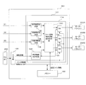
- Embodiment 35 of the present invention It is a front view of an indoor unit according to Embodiment 35 of the present invention. It is a block diagram which shows the control apparatus which concerns on Embodiment 35 of this invention. It is a front view which shows another example of the indoor unit which concerns on Embodiment 35 of this invention. It is a left view of the indoor unit shown in FIG. It is a front view which shows another example of the indoor unit which concerns on Embodiment 35 of this invention. It is a front view which shows the indoor unit which concerns on Embodiment 36 of this invention. It is a block diagram which shows the control apparatus which concerns on Embodiment 36 of this invention. It is a front view which shows the indoor unit which concerns on Embodiment 37 of this invention.
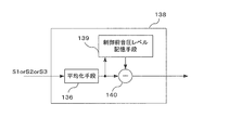
- FIG. 90 is a left side view of the indoor unit shown in FIG. 89. It is a front view which shows another example of the indoor unit which concerns on Embodiment 38 of this invention. It is a front view which shows the indoor unit which concerns on Embodiment 41 of this invention. It is a block diagram which shows the control apparatus which concerns on Embodiment 41 of this invention. It is a block diagram which shows the silence volume calculation means which concerns on Embodiment 41 of this invention. It is a front view which shows the indoor unit which concerns on Embodiment 42 of this invention.
- each unit constituting the indoor unit of the air conditioner will be described.
- the fifth and subsequent embodiments the detailed configuration of each unit or another example will be described.
- the present invention will be described by taking a wall-mounted indoor unit as an example.
- the shape and size of each unit (or a constituent member of each unit) may be partially different.
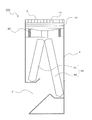
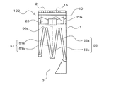
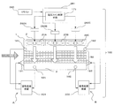
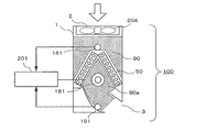
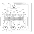
- FIG. 1 is a longitudinal sectional view showing an indoor unit (referred to as an indoor unit 100) of an air conditioner according to Embodiment 1 of the present invention.
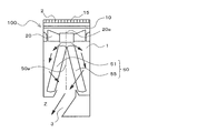
- FIG. 2 is an external perspective view showing the indoor unit.
- the left side in FIG. 1 will be described as the front side of the indoor unit 100.
- the configuration of the indoor unit 100 will be described with reference to FIGS. 1 and 2.
- the indoor unit 100 supplies conditioned air to an air-conditioning target area such as a room by using a refrigeration cycle that circulates a refrigerant.
- the indoor unit 100 is mainly accommodated in a casing 1 in which a suction port 2 for sucking indoor air into the interior and a blower outlet 3 for supplying conditioned air to an air-conditioning target area are formed.
- the fan 20 sucks room air from the suction port 2 and blows out the conditioned air from the blower outlet 3 and the air passage from the fan 20 to the blower outlet 3, and exchanges heat between the refrigerant and the room air for conditioned air.
- a heat exchanger 50 for producing And the air path (arrow Z) is connected in the casing 1 by these components.
- the suction port 2 is formed in the upper part of the casing 1.
- the blower outlet 3 has an opening formed in the lower part of the casing 1 (more specifically, on the lower side of the front part of the casing 1).
- the fan 20 is disposed on the downstream side of the suction port 2 and on the upstream side of the heat exchanger 50, and is configured by, for example, an axial flow fan or a diagonal flow fan.
- the indoor unit 100 includes a control device 281 that controls the rotation speed of the fan 20 and the directions (angles) of the upper and lower vanes 70 and the left and right vanes 80 described later.
- the controller 281 may not be shown in the drawings shown in the first embodiment and each embodiment described later.
- the fan 20 is provided on the upstream side of the heat exchanger 50, so that it is compared with a conventional air conditioner indoor unit in which the fan 20 is provided at the outlet 3.
- the generation of the swirling flow of the air blown from the outlet 3 and the variation in the wind speed distribution can be suppressed. For this reason, comfortable ventilation to an air-conditioning object area is attained.
- there is no complicated structure such as a fan at the air outlet 3 it is easy to take measures against condensation that occurs at the boundary between warm air and cold air during cooling operation.
- the fan motor 30 is not exposed to cold air or warm air that is air-conditioned air, a long operating life can be provided.
- the indoor unit 100 according to Embodiment 1 includes three fans 20 arranged in parallel along the longitudinal direction of the casing 1 (in other words, the longitudinal direction of the air outlet 3). Yes.
- approximately two to four fans 20 are preferable.
- all the fans 20 are configured in the same shape, and almost the same amount of air flow can be obtained by all the fans 20 by operating all the operation rotational speeds equally.
- the optimum fan design corresponding to the indoor unit 100 of various specifications can be achieved by combining the number, shape, size, and the like of the fans 20 according to the required air volume and the ventilation resistance inside the indoor unit 100. Is possible.
- a bell mouth 5 on a duct is disposed around the fan 20.
- the bell mouth 5 is for smoothly guiding the intake and exhaust of air to the fan.
- the bell mouth 5 according to the first embodiment has a substantially circular shape in plan view.
- the bell mouth 5 according to the first embodiment has the following shape.
- the upper part 5a has a substantially arc shape whose end part widens upward.
- the central portion 5b is a straight portion where the diameter of the bell mouth is constant.
- the lower part 5c has a substantially arc shape whose end part extends downward.
- the suction inlet 2 is formed in the edge part (arc part of the suction side) of the upper part 5a of the bellmouth 5.
- FIG. 1 of the first embodiment has a duct shape configured higher than the height of the impeller of the fan 20, but is not limited thereto, and the height of the bell mouth 5 is not limited thereto.
- a semi-open bellmouth configured lower than the height of the impeller of the fan 20 may be used.
- the bell mouth 5 may not be provided with the straight portion 5b shown in FIG. 1 but may be constituted only by the end portions 5a and 5c.
- the bell mouth 5 may be formed integrally with the casing 1, for example, in order to reduce the number of parts and improve the strength. Further, for example, the bell mouth 5, the fan 20, the fan motor 30, and the like may be modularized, and the casing 1 may be attached and detached to improve maintenance.
- the end of the upper portion 5a of the bell mouth 5 (arc portion on the suction side) is configured in a uniform shape with respect to the circumferential direction of the opening surface of the bell mouth 5.
- the bell mouth 5 has no structure such as a notch or a rib with respect to the rotation direction about the rotation axis 20a of the fan 20, and has a uniform shape having axial symmetry.
- the end of the upper portion 5a of the bell mouth 5 (the arc portion on the suction side) has a uniform shape with respect to the rotation of the fan 20.
- a uniform flow is realized as a flow. For this reason, the noise which generate
- partition plate 90 As shown in FIG. 2, in the indoor unit 100 according to the first embodiment, a partition plate 90 is provided between adjacent fans 20. These partition plates 90 are installed between the heat exchanger 50 and the fan 20. That is, the air path between the heat exchanger 50 and the fan 20 is divided into a plurality of air paths (three in the first embodiment). Since the partition plate 90 is installed between the heat exchanger 50 and the fan 20, the end on the side in contact with the heat exchanger 50 has a shape along the heat exchanger 50. More specifically, as shown in FIG. 1, the heat exchanger 50 includes a longitudinal section from the front side to the rear side of the indoor unit 100 (that is, a longitudinal section when the indoor unit 100 is viewed from the right side. Are arranged in a substantially ⁇ shape. For this reason, the heat exchanger 50 side end part of the partition plate 90 is also substantially [Lambda] type.
- the position of the end portion of the partition plate 90 on the fan 20 side may be determined as follows, for example.
- the end of the partition plate 90 on the fan 20 side may be extended to the outlet surface of the fan 20.
- the adjacent fans 20 are close enough to influence each other on the suction side, and the shape of the end of the upper portion 5a of the bell mouth 5 (arc portion on the suction side) can be formed sufficiently large.
- the end of the plate 90 on the fan 20 side extends to the upstream side (suction side) of the fan 20 so as not to affect the adjacent air path (so that the adjacent fans 20 do not affect each other on the suction side). It may be extended.
- the partition plate 90 can be formed of various materials.
- the partition plate 90 may be formed of a metal such as steel or aluminum.
- the partition plate 90 may be formed of resin or the like.
- the heat exchanger 50 becomes a high temperature during the heating operation, when the partition plate 90 is formed of a low melting point material such as a resin, the heat exchanger 50 is slightly between the partition plate 90 and the heat exchanger 50. A good space should be formed.
- the partition plate 90 is made of a material having a high melting point such as aluminum or steel, the partition plate 90 may be disposed in contact with the heat exchanger 50.
- the heat exchanger 50 is, for example, a fin tube type heat exchanger, a partition plate 90 may be inserted between the fins of the heat exchanger 50.
- the air path between the heat exchanger 50 and the fan 20 is divided into a plurality of air paths (three in the first embodiment).
- a noise absorbing material can be provided in this air passage, that is, in the partition plate 90 and the casing 1 to reduce noise generated in the duct.
- these divided air paths are formed in a substantially square shape with one side being L1 and L2 in a plan view. That is, the width of the divided air path is L1 and L2. For this reason, for example, the amount of air generated by the fan 20 installed inside the substantially square shape formed by L1 and L2 is reliably transferred to the heat exchanger 50 in the region surrounded by L1 and L2 downstream of the fan 20. pass.
- the air blown from each fan 20 is blown into the indoor unit 100 even if the flow field created downstream by the fan 20 has a swirling component. Cannot move freely in the longitudinal direction (the direction perpendicular to the plane of FIG. 1). For this reason, the air blown out by the fan 20 can be passed through the heat exchanger 50 in the region surrounded by L1 and L2 downstream of the fan 20. As a result, variation in the air volume distribution in the longitudinal direction of the indoor unit 100 flowing into the entire heat exchanger 50 (in the direction orthogonal to the plane of FIG. 1) can be suppressed, and high heat exchange performance can be achieved.
- each partition plate 90 does not need to be formed with a single plate, and may be formed with a plurality of plates.
- the partition plate 90 may be divided into two parts on the front side heat exchanger 51 side and the back side heat exchanger 55 side. Needless to say, it is preferable that there is no gap at the joint between the plates constituting the partition plate 90. By dividing the partition plate 90 into a plurality of parts, the assembling property of the partition plate 90 is improved.
- the fan 20 is rotationally driven by a fan motor 30.
- the fan motor 30 used may be an inner rotor type or an outer rotor type.
- the outer rotor type fan motor 30 a structure in which the rotor is integrated with the boss 21 of the fan 20 (the boss 21 is provided with a rotor) is also used. Further, by making the size of the fan motor 30 smaller than the size of the boss 21 of the fan 20, it is possible to prevent loss of the airflow generated by the fan 20. Further, by arranging a motor inside the boss 21, the axial dimension can be reduced. By making the fan motor 30 and the fan 20 easy to attach and detach, the maintainability is also improved.
- the use of a relatively expensive DC brushless motor as the fan motor 30 can improve efficiency, extend the service life, and improve the controllability. However, even if other types of motors are used, air conditioning It goes without saying that the primary function of the machine is satisfied. Further, the circuit for driving the fan motor 30 may be integrated with the fan motor 30 or may be configured externally to take dust and fire prevention measures.
- the fan motor 30 is attached to the casing 1 by a motor stay 16. Further, the fan motor 30 is a box type (fan 20, housing, fan motor 30, bell mouth 5, motor stay 16 and the like are integrated into a module) used for CPU cooling and the like, and is detachable from the casing 1. If the structure is possible, the maintainability is improved and the accuracy of the chip clearance of the fan 20 can be increased. In general, a narrow tip clearance is preferable because of high air blowing performance.
- the drive circuit of the fan motor 30 may be configured inside the fan motor 30 or may be outside.
- the motor stay 16 includes a fixing member 17 and a support member 18.
- the fixing member 17 is to which the fan motor 30 is attached.
- the support member 18 is a member for fixing the fixing member 17 to the casing 1.
- the support member 18 is, for example, a rod-like member, and extends from the outer peripheral portion of the fixing member 17, for example, radially. As shown in FIG. 1, the support member 18 according to the first embodiment extends approximately in the horizontal direction.
- the support member 18 may provide a stationary blade effect as a blade shape or a plate shape.
- the heat exchanger 50 of the indoor unit 100 according to Embodiment 1 is arranged on the leeward side of the fan 20.
- the heat exchanger 50 for example, a fin tube heat exchanger or the like may be used.
- the heat exchanger 50 is divided by a symmetry line 50a in the right vertical section.
- the symmetry line 50a divides the installation range of the heat exchanger 50 in this cross section in the left-right direction at a substantially central portion. That is, the front side heat exchanger 51 is on the front side (left side in FIG. 1) with respect to the symmetry line 50a, and the rear side heat exchanger 55 is on the back side (right side in FIG. 1) with respect to the symmetry line 50a.
- Each is arranged.
- the front-side heat exchanger 51 and the rear-side heat exchanger 55 are arranged so that the distance between the front-side heat exchanger 51 and the rear-side heat exchanger 55 widens with respect to the air flow direction, that is, the right-side longitudinal section.
- the heat exchanger 50 is arranged in the casing 1 so that the cross-sectional shape of the heat exchanger 50 is substantially ⁇ -shaped. That is, the front side heat exchanger 51 and the back side heat exchanger 55 are arranged so as to be inclined with respect to the flow direction of the air supplied from the fan 20.
- the heat exchanger 50 is characterized in that the air passage area of the rear heat exchanger 55 is larger than the air passage area of the front heat exchanger 51. That is, in the heat exchanger 50, the air volume of the back side heat exchanger 55 is larger than the air volume of the front side heat exchanger 51.
- the longitudinal length of the back side heat exchanger 55 is longer than the longitudinal length of the front side heat exchanger 51 in the right vertical section.
- the air path area of the back surface side heat exchanger 55 is larger than the air path area of the front surface side heat exchanger 51.
- the other configurations (such as the length in the depth direction in FIG. 1) of the front side heat exchanger 51 and the back side heat exchanger 55 are the same. That is, the heat transfer area of the back side heat exchanger 55 is larger than the heat transfer area of the front side heat exchanger 51.
- the rotating shaft 20a of the fan 20 is installed above the symmetry line 50a.
- the heat exchanger 50 By configuring the heat exchanger 50 in this manner, the generation of a swirling flow of the air blown from the blower outlet 3 and the distribution of the wind speed are compared with a conventional air conditioner indoor unit in which a fan is provided at the blower outlet. Occurrence can be suppressed.
- the air volume of the back side heat exchanger 55 is larger than the air volume of the front side heat exchanger 51. And when the air which passed each of the front side heat exchanger 51 and the back side heat exchanger 55 merges by this air volume difference, this merged air will bend to the front side (blower outlet 3 side). For this reason, it is no longer necessary to bend the airflow rapidly in the vicinity of the outlet 3, and the pressure loss in the vicinity of the outlet 3 can be reduced.
- the flow direction of the air flowing out from the back side heat exchanger 55 is the flow from the back side to the front side. For this reason, the indoor unit 100 according to the first embodiment bends the flow of air after passing through the heat exchanger 50, as compared with the case where the heat exchanger 50 is arranged in a substantially v shape in the right vertical section. It becomes easy.
- the indoor unit 100 has a plurality of fans 20 and thus tends to be heavy.
- the strength of the wall surface for installing the indoor unit 100 is required, which is a restriction on installation. For this reason, it is preferable to reduce the weight of the heat exchanger 50.
- positions the fan 20 in the upstream of the heat exchanger 50 the height dimension of the indoor unit 100 becomes large and tends to become restrictions on installation. For this reason, it is preferable to reduce the weight of the heat exchanger 50.
- a fin tube heat exchanger is used as the heat exchanger 50 (the front side heat exchanger 51 and the back side heat exchanger 55), and the heat exchanger 50 is downsized.
- the heat exchanger 50 according to the first embodiment includes a plurality of fins 56 stacked via a predetermined gap, and a plurality of heat transfer tubes 57 penetrating the fins 56.
- the fins 56 are stacked in the left-right direction of the casing 1 (the direction orthogonal to the plane of FIG. 1). That is, the heat transfer tube 57 passes through the fin 56 along the left-right direction of the casing 1 (the direction orthogonal to the plane of FIG. 1).
- Embodiment 1 in order to improve the heat exchange efficiency of the heat exchanger 50, two rows of heat transfer tubes 57 are arranged in the ventilation direction of the heat exchanger 50 (the width direction of the fins 56). These heat transfer tubes 57 are arranged in a substantially zigzag shape in the right vertical section.
- the heat transfer tube 57 is formed by a thin tube (diameter of about 3 mm to 7 mm) and the refrigerant flowing through the heat transfer tube 57 (the refrigerant used in the indoor unit 100 and the air conditioner equipped with the indoor unit 100) is R32.
- the heat exchanger 50 is reduced in size. That is, the heat exchanger 50 exchanges heat between the refrigerant flowing in the heat transfer tube 57 and the room air via the fins 56. For this reason, when the heat transfer tube 57 is made thin, the pressure loss of the refrigerant becomes large at the same refrigerant circulation amount as compared with a heat exchanger having a large heat transfer tube diameter.
- R32 has a larger latent heat of vaporization at the same temperature than R410A, and can exhibit the same ability with a smaller amount of refrigerant circulation. For this reason, by using R32, the amount of refrigerant to be used can be reduced, and the pressure loss in the heat exchanger 50 can be reduced. Therefore, the heat exchanger 50 can be reduced in size by configuring the heat transfer tube 57 as a thin circular tube and using R32 as the refrigerant.
- the heat exchanger 50 is reduced in weight by forming the fins 56 and the heat transfer tubes 57 from aluminum or an aluminum alloy.
- the weight of the heat exchanger 50 does not become an installation-like restriction
- the finger guard 15 and the filter 10 are provided at the suction port 2.
- the finger guard 15 is installed for the purpose of preventing the rotating fan 20 from being touched.
- the shape of the finger guard 15 is arbitrary as long as the hand cannot be touched to the fan 20.
- the shape of the finger guard 15 may be a lattice shape, or may be a circular shape formed of a large number of different rings.
- the finger guard 15 may be made of a material such as a resin or a metal material. However, when strength is required, the finger guard 15 is preferably made of a metal.
- the finger guard 15 is preferably as thin and strong as possible from the viewpoint of lowering ventilation resistance and maintaining strength.
- the filter 10 is provided to prevent dust from flowing into the indoor unit 100.
- the filter 10 is detachably provided on the casing 1.
- the indoor unit 100 which concerns on this Embodiment 1 may be provided with the automatic cleaning mechanism which cleans the filter 10 automatically.
- the indoor unit 100 which concerns on this Embodiment 1 is provided in the blower outlet 3 with the up-and-down vane 70 and the right-and-left vane (not shown) which are mechanisms which control the blowing direction of airflow.
- FIG. 3 is a perspective view of the indoor unit according to Embodiment 1 of the present invention as viewed from the front right side.
- FIG. 4 is a perspective view of the indoor unit as viewed from the rear right side.
- FIG. 5 is a perspective view of the indoor unit as viewed from the front left side.
- FIG. 6 is a perspective view showing the drain pan according to Embodiment 1 of the present invention.
- the right side of the indoor unit 100 is shown in cross section
- FIG. 5 the left side of the indoor unit 100 is shown in cross section.
- a front side drain pan 110 is provided below a lower end portion of the front side heat exchanger 51 (a front side end portion of the front side heat exchanger 51).
- a back side drain pan 115 is provided below the lower end portion of the back side heat exchanger 55 (the back side end of the back side heat exchanger 55).
- the back side drain pan 115 and the back portion 1b of the casing 1 are integrally formed.
- the back side drain pan 115 is provided with connection ports 116 to which the drain hose 117 is connected at both the left end and the right end. In addition, it is not necessary to connect the drain hose 117 to both the connection ports 116, and the drain hose 117 may be connected to one of the connection ports 116.
- the drain hose 117 when the drain hose 117 is to be pulled out to the right side of the indoor unit 100 during the installation work of the indoor unit 100, the drain hose 117 is connected to the connection port 116 provided at the right end of the back side drain pan 115, and the back side
- the connection port 116 provided at the left end of the drain pan 115 may be closed with a rubber cap or the like.
- the front side drain pan 110 is disposed at a position higher than the back side drain pan 115. Further, between the front side drain pan 110 and the back side drain pan 115, a drainage channel 111 serving as a drain moving path is provided at both the left end and the right end.
- the drainage channel 111 has a front end connected to the front drain pan 110 and is provided so as to incline downward from the front drain pan 110 toward the rear drain pan 115.
- a tongue portion 111 a is formed at the end of the drainage channel 111 on the back side. The rear end of the drainage channel 111 is disposed so as to cover the upper surface of the back side drain pan 115.
- the front-side drain pan 110 is provided at a position higher than the back-side drain pan 115, so that the drain collected by the front-side drain pan 110 is directed toward the back-side drain pan 115 toward the drainage channel 111. Flowing.
- the drain is dropped from the tongue 111 a of the drainage channel 111 to the back side drain pan 115 and collected by the back side drain pan 115.
- the drain collected by the back side drain pan 115 passes through the drain hose 117 and is discharged to the outside of the casing 1 (indoor unit 100).
- the drain collected by both drain pans is disposed on the back-side drain pan 115 (most rear side of the casing 1). Can be collected in the drain pan).
- the connection port 116 of the drain hose 117 in the back side drain pan 115 the drain collected by the front side drain pan 110 and the back side drain pan 115 can be discharged to the outside of the casing 1. Therefore, when performing maintenance (such as cleaning the heat exchanger 50) of the indoor unit 100 by opening the front surface of the casing 1, it is not necessary to attach or detach the drain pan to which the drain hose 117 is connected. Improves.
- the drainage channels 111 are provided at both the left end and the right end, even if the indoor unit 100 is installed in an inclined state, the drain collected by the front side drain pan 110 can be surely received from the back side drain pan. 115.
- the connection ports for connecting the drain hose 117 are provided at both the left end and the right end, the hose pull-out direction can be selected according to the installation conditions of the indoor unit 100, and the indoor unit 100 The workability when installing is improved.
- the drainage channel 111 is disposed so as to cover the backside drain pan 115 (that is, a connection mechanism is not required between the drainage channel 111 and the backside drain pan 115), the front side drain pan 110 is disposed. It becomes easy to attach and detach, and the maintainability is further improved.
- the drainage channel 111 may be disposed so that the rear side end of the drainage channel 111 is connected to the rear side drain pan 115 and the front side drain pan 110 covers the drainage channel 111. Even in such a configuration, it is possible to obtain the same effect as the configuration in which the drainage channel 111 is disposed so as to cover the back side drain pan 115. Further, the front-side drain pan 110 does not necessarily need to be higher than the rear-side drain pan 115. Even if the front-side drain pan 110 and the rear-side drain pan 115 have the same height, the drain collected by both drain pans is connected to the rear-side drain pan 115. The drainage hose can be discharged.
- the indoor unit 100 according to Embodiment 1 has an opening length d1 on the entrance side of the nozzle 6 in the right vertical section (between the drain pans defined between the front-side drain pan 110 and the back-side drain pan 115 portion.
- the throttle length d1) is configured to be larger than the opening length d2 on the outlet side of the nozzle 6 (the length of the outlet 3). That is, the nozzle 6 of the indoor unit 100 satisfies d1> d2 (see FIG. 1).
- d2 of the indoor unit 100 according to the first embodiment is approximately the same as the air outlet of the conventional indoor unit. It will be described as being length.
- the air passage becomes larger and the angle A of the heat exchanger 50 arranged on the upstream side (the front side heat on the downstream side of the heat exchanger 50). It is possible to increase the angle formed by the exchanger 51 and the back side heat exchanger 55. For this reason, the wind speed distribution generated in the heat exchanger 50 is relaxed, and the air path downstream of the heat exchanger 50 can be formed large, so that the pressure loss of the entire indoor unit 100 can be reduced. Furthermore, the deviation of the wind speed distribution that has occurred near the inlet of the nozzle 6 can be made uniform by the effect of contraction and guided to the outlet 3.
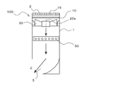
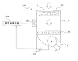
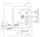
- the indoor unit 100 according to Embodiment 1 is provided with an active silencing mechanism as shown in FIG.
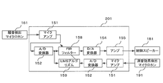
- the silencing mechanism of the indoor unit 100 includes a noise detection microphone 161, a control speaker 181, a silencing effect detection microphone 191, and a signal processing device 201.
- the noise detection microphone 161 is a noise detection device that detects the operation sound (noise) of the indoor unit 100 including the blowing sound of the fan 20.
- the noise detection microphone 161 is disposed between the fan 20 and the heat exchanger 50. In the first embodiment, it is provided on the front surface in the casing 1.
- the control speaker 181 is a control sound output device that outputs a control sound for noise.
- the control speaker 181 is disposed below the noise detection microphone 161 and above the heat exchanger 50.
- the silencing effect detection microphone 191 is a silencing effect detection device that detects the silencing effect by the control sound.
- the muffler effect detection microphone 191 is provided in the vicinity of the air outlet 3 in order to detect noise coming from the air outlet 3. Further, the muffler effect detection microphone 191 is attached at a position avoiding the wind flow so as not to hit the blown air coming out of the blowout port 3.
- the signal processing device 201 is a control sound generation device that causes the control speaker 181 to output a control sound based on the detection results of the noise detection microphone 161 and the silencing effect detection microphone 191.
- the signal processing device 201 is accommodated in the control device 281, for example.
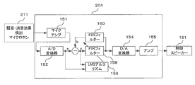
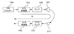
- FIG. 8 is a block diagram showing the signal processing apparatus according to Embodiment 1 of the present invention.
- Electric signals input from the noise detection microphone 161 and the muffler effect detection microphone 191 are amplified by the microphone amplifier 151 and converted from an analog signal to a digital signal by the A / D converter 152.
- the converted digital signal is input to the FIR filter 158 and the LMS algorithm 159.
- the FIR filter 158 generates a control signal that has been corrected so that the noise detected by the noise detection microphone 161 has the same amplitude and opposite phase as the noise when the noise reduction effect detection microphone 191 is installed.
- the indoor unit 100 is provided with a water receptacle or the like (not shown) for preventing water droplets from coming out of the air outlet 3 in the vicinity of the air outlet 3.
- a water receptacle or the like not shown
- positioned is upstream of the area
- the operation sound (noise) including the blowing sound of the fan 20 in the indoor unit 100 is detected by the noise detection microphone 161 attached between the fan 20 and the heat exchanger 50, and the microphone amplifier 151 and the A / D converter 152 are detected. And is input to the FIR filter 158 and the LMS algorithm 159.
- the tap coefficients of the FIR filter 158 are sequentially updated by the LMS algorithm 159.
- the coefficient is updated.
- h is a filter tap coefficient
- e is an error signal
- x is a filter input signal
- ⁇ is a step size parameter.
- the step size parameter ⁇ controls a filter coefficient update amount for each sampling.
- the digital signal that has passed through the FIR filter 158 whose tap coefficient has been updated by the LMS algorithm 159 is converted to an analog signal by the D / A converter 154, amplified by the amplifier 155, and the fan 20 and heat exchanger. 50 is emitted as a control sound from the control speaker 181 attached between the indoor unit 100 and the air passage in the indoor unit 100.
- the sound is transmitted from the fan 20 through the air path to the muffler effect detection microphone 191 attached in the direction of the outer wall of the air outlet 3 so that the wind emitted from the air outlet 3 does not hit.
- the sound after the control sound emitted from the control speaker 181 interferes with the noise coming out from the blow outlet 3 is detected. Since the sound detected by the muffling effect detection microphone 191 is input to the error signal of the LMS algorithm 159 described above, the tap coefficient of the FIR filter 158 is updated so that the sound after the interference approaches zero. become. As a result, noise in the vicinity of the air outlet 3 can be suppressed by the control sound that has passed through the FIR filter 158.
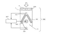
- the noise detection microphone 161 and the control speaker 181 are arranged between the fan 20 and the heat exchanger 50, and the silencing effect detection microphone 191 is connected to the blower outlet 3. It is installed in the place where the wind current does not hit. For this reason, since it is not necessary to attach a member that requires active silencing to the region B where condensation occurs, water droplets are prevented from adhering to the control speaker 181, the noise detecting microphone 161, and the silencing effect detecting microphone 191, and the silencing performance is deteriorated. The failure of the speaker and microphone can be prevented.
- the mounting positions of the noise detection microphone 161, the control speaker 181 and the mute effect detection microphone 191 shown in the first embodiment are merely examples.
- the noise reduction effect detection microphone 191 may be disposed between the fan 20 and the heat exchanger 50 together with the noise detection microphone 161 and the control speaker 181.
- the microphone has been exemplified as a means for detecting the silencing effect after the noise is canceled by the noise or the control sound, it may be configured by an acceleration sensor or the like that detects the vibration of the casing.
- the sound may be regarded as air flow disturbance, and the noise reduction effect after the noise is canceled by noise or control sound may be detected as air flow disturbance.
- a flow rate sensor, a hot wire probe, or the like that detects an air flow may be used as a means for detecting a silencing effect after noise is canceled by noise or control sound. It is also possible to detect the air flow by increasing the gain of the microphone.
- the FIR filter 158 and the LMS algorithm 159 are used in the signal processing device 201.
- any adaptive signal processing circuit that brings the sound detected by the mute effect detection microphone 191 close to zero may be active.
- a filtered-X algorithm that is generally used in the dynamic silencing method may be used.
- the signal processing device 201 may be configured to generate the control sound by a fixed tap coefficient instead of the adaptive signal processing.
- the signal processing device 201 may be an analog signal processing circuit instead of digital signal processing.
- the present invention is applicable even when the heat exchanger 50 that does not cause condensation is disposed. Therefore, it is possible to prevent performance deterioration of the noise detection microphone 161, the control speaker 181, the silencing effect detection microphone 191, and the like without considering the presence or absence of dew condensation due to the heat exchanger 50.
- FIG. ⁇ Motor support structure> For example, noise can be suppressed by attaching the fan 20 to the casing 1 with the motor stay 16 as described below.
- the same functions and configurations as those in the first embodiment will be described using the same reference numerals.
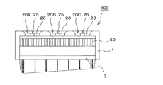
- FIG. 10 is a longitudinal sectional view showing the indoor unit according to Embodiment 2 of the present invention.
- the indoor unit 100 according to the second embodiment includes a fan 20 in which a fan motor 30 is connected to a boss 21.
- the fan motor 30 is attached to the casing 1 by a motor stay 16.
- the motor stay 16 includes a fixing member 17 and a support member 18.
- the fixing member 17 is to which the fan motor 30 is attached.
- the support member 18 is a member for fixing the fixing member 17 to the casing 1.
- the support member 18 is, for example, a rod-like member, and extends from the outer peripheral portion of the fixing member 17, for example, radially.
- the filter 10 is provided on the downstream side of the fan 20.
- the motor stay 16 and the filter 10 are provided close to each other (for example, both are in contact with each other).
- the support member 18 may provide a stationary blade effect as a blade shape or a plate shape.
- the airflow discharged from the fan 20 has a velocity distribution.
- the airflow having this velocity distribution collides with a downstream structure (for example, the motor stay 16), so that noise synchronized with the product of the rotational speed of the fan 20 and the number of blades is generated.
- a member having ventilation resistance is installed downstream of the fan 20
- the filter 10 (a member having ventilation resistance) is installed downstream of the fan 20.
- a motor stay 16, which is a main structure of the noise generation source, is installed in the vicinity of the filter 10. For this reason, since the airflow with a reduced velocity distribution collides with the motor stay 16, the amount of fluctuation of the load applied to the motor stay 16 is reduced, and noise generated from the motor stay 16 can be suppressed.
- the motor stay 16 is installed in the vicinity of the filter 10” indicates the following state.
- a steep velocity deficit region region where the flow velocity is slow
- the length of the velocity deficit area in the airflow direction is approximately the same as the dimension of the motor stay 16 projected in the airflow direction. Since the velocity deficit region is a portion where the velocity change of the air current is remarkable, strong vortices and turbulence of the air current are generated in the velocity deficit region due to the shearing force due to the velocity difference of the air current. As the strong vortex and air current turbulence occur, the amount of noise generated increases.
- the wake (downstream airflow) of the fan 20 has a complex flow velocity distribution
- the direction of the airflow that collides with the motor stay 16 varies.
- the support member 18 of the motor stay 16 is cut along a cross section orthogonal to the longitudinal direction of the support member 18 and the maximum projection dimension is the maximum projection dimension among the projection dimensions of this cross section, This is substantially equal to the maximum projected dimension. That is, by making the distance between the motor stay 16 and the filter 10 smaller than the maximum projected dimension, it is possible to suppress the generation of noise due to the turbulence of the airflow that occurs in the velocity deficient region.
- the motor stay 16 is installed in the vicinity of the filter 10” means that the motor stay 16 is arranged so that the distance between the motor stay 16 and the filter 10 is smaller than the maximum projected dimension. This means that it is installed upstream of the filter 10.
- the filter 10 is provided below the motor stay 16 (that is, downstream), but the filter 10 may be provided above the motor stay 16 (that is, upstream) as shown in FIG.
- the filter 10 is provided above the motor stay 16, it is not necessary to provide the motor stay 16 and the filter 10 close to each other. Since the velocity distribution of the airflow that has passed through the filter is small, noise generated from the motor stay 16 can be suppressed as described above.
- a moving guide for the filter 10 may be formed in the motor stay 16. Furthermore, it is desirable that the distance between the filter 10 as the ventilation resistor and the fan 20 is at least 25% of the fan 20 diameter.
- the motor stay 16 into the following shape, noise generated from the motor stay 16 can be further suppressed.
- FIG. 12 is a front view showing an example of a motor stay according to Embodiment 2 of the present invention (a plan view when the motor stay is attached to the indoor unit).
- the motor stay 16 shown in FIG. 12 has rod-shaped support members 18 extending radially from a substantially disk-shaped fixing member 17. These support members 18 have shapes that do not match the rear edge shape of the blades 23 of the fan 20.
- the support member 18 is formed in a curved shape, but the support member 18 may be formed in a linear shape. With this configuration, it is possible to prevent a large load from being applied to the support member 18 due to the overlapping of the rear edge portion of the blade 23 of the support member 18 and the fan 20, and further suppress noise generated from the motor stay 16. Can do.
- the number of support members 18 of the motor stay 16 and the number of blades 23 of the fan 20 may be in a prime relationship.
- the motor stay 16 By configuring the motor stay 16 in this way, it is possible to prevent the load on all the support members 18 from being in the maximum load state (the state in which the maximum load of the fluctuation amount of the load on the support member 18 is applied). The noise generated from the motor stay 16 can be further suppressed.
- the noise generated from the motor stay 16 can be further suppressed even if the motor stay 16 has a cross-sectional shape that is dull in the air flow direction, and does not easily induce air flow separation. Furthermore, by providing a soft hair material on the surface of the motor stay 16, it is possible to suppress pressure fluctuations on the surface of the motor stay 16, and to further reduce the generation of noise.
- the mounting structure of the fan motor 30 to the fixing member 17 is not particularly limited. As shown in FIG. 13, a fan motor 30 may be attached to the fixing member 17.
- FIGS. 13 to 16 are perspective views showing examples of mounting the fan motor to the fixing member of the motor stay according to Embodiment 2 of the present invention.
- FIG. 13 even if the fan motor 30 is fixed by providing the fixing member 17 with a through hole 17a penetrating in the vertical direction and screwing the fan motor 30 with a screw inserted into the through hole 17a. Good.
- the fan motor 30 is screwed, as shown in FIG. 14, the fan motor 30 is inserted into the fixing member 17 and the fan motor 30 is screwed by forming the through hole 17 a on the side surface of the fixing member 17. Good.
- the fixing member may be constituted by two fixing members 17b obtained by dividing the ring member.
- the fan motor 30 may be fixed to the fixing member 17 by sandwiching the fan motor 30 with the fixing members 17b and fixing the fixing members 17b to each other with screws.
- the strength of the shell portion having the weakest strength among the fan motors 30 can be improved. Since the shell portion having the weakest strength in the fan motor 30 is a portion that emits motor noise, the noise emitted from the fan motor 30 can be suppressed by improving the strength of the portion.
- the fan motor 30 may be fixed to the fixing member 17 by combining a plurality of fixing structures shown in FIGS. In FIG. 16, the fan motor 30 is fixed to the fixing member 17 by using two fixing structures shown in FIG. 15. By fixing the fan motor 30 at two points as described above, an effect of suppressing the swing of the fan motor 30 due to vibration or rotational imbalance can be obtained. Further, it goes without saying that a vibration isolator is provided on the fixing member 17 shown in FIGS. 13 to 16 to weaken the transmission of vibration to the casing 1.
- the indoor unit 100 including the fan 20 in which the fan motor 30 is connected to the boss 21 has been described.
- the indoor unit 100 provided with 20 may be sufficient.
- a support structure 35 (see FIG. 17 described later) that is rotatably attached to the boss 21 may be fixed to the fixing member of the motor stay 16.
- the motor stay 16 and the filter 10 may be integrally formed so that the motor stay 16 functions as a reinforcing member for the filter 10. Since the reinforcing member provided in the conventional filter is not necessary, the cost can be reduced by the amount of the reinforcing member.
- Embodiment 3 The motor stay 16 for attaching the fan 20 to the casing 1 may be configured as follows.
- items that are not particularly described are the same as those in the second embodiment, and the same functions and configurations are described using the same reference numerals.
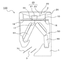
- FIG. 17 is a longitudinal sectional view showing the indoor unit according to Embodiment 3 of the present invention.
- FIG. 18 is an external perspective view showing the indoor unit. Note that FIG. 18 shows the casing 1 through. 17 and 18 include the indoor unit 100 including the fan 20 in which the fan motor 30 is provided between the blade 23 and the casing 26.
- the motor stay 16 according to the third embodiment is configured by a fixing member 17 provided along the longitudinal direction of the indoor unit 100. Both ends of the fixing member 17 in the longitudinal direction are fixed to the casing 1. And, to this fixing member 17, a support structure 35 (one that rotatably supports the boss 21 of the fan 20) of each of the three fans 20 is fixed. Further, the fixing member 17 is located above the transmutation portion of the heat exchanger 50 (the location where the arrangement gradient of the heat exchanger 50 is transformed, that is, the location where the front side heat exchanger 51 and the back side heat exchanger 55 are connected). Is provided. Although the motor stay 16 according to the third embodiment is configured not to include the support member 18, the fixing member 17 may be fixed to the casing 1 by the support member 18.
- Embodiment 4 FIG. Moreover, you may comprise the motor stay 16 which attaches the fan 20 to the casing 1 as follows.
- items that are not particularly described are the same as those in Embodiment 2 or Embodiment 3, and the same functions and configurations are described using the same reference numerals.
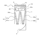
- FIG. 19 is a longitudinal sectional view showing an indoor unit according to Embodiment 4 of the present invention.
- the distance between the support member 18 and the rear edge of the blade 23 of the fan 20 is the tip of the blade 23 (the outer peripheral portion of the impeller 25) in a side view. It is configured to grow as you go.
- the airflow generated by the fan 20 increases toward the tip of the blade 23 (the outer peripheral portion of the impeller 25). That is, when the distance between the support member 18 and the trailing edge of the blade 23 is the same at the root portion and the tip portion of the blade 23, the load fluctuation amount related to the motor stay 16 is the tip portion of the blade 23 (the outer peripheral portion of the impeller 25). ) Grows toward However, in the fourth embodiment, the distance between the support member 18 and the rear edge of the blade 23 of the fan 20 is configured to increase toward the tip of the blade 23 (the outer peripheral portion of the impeller 25). Therefore, it is possible to suppress the load fluctuation amount related to the motor stay 16.
- the motor stay 16 having the configuration shown in the fourth embodiment, the motor stay 16 having a configuration in which the distance between the support member 18 and the rear edge of the blade 23 is the same at the root portion and the tip portion of the blade 23. As compared with the above, noise generated from the motor stay 16 can be further suppressed.
- Embodiment 5 FIG. ⁇ Fan & Fan Motor>
- an example of fan 20 provided in indoor unit 100 according to Embodiments 1 to 4 will be described.
- the fan 20 provided in the indoor unit 100 according to Embodiment 1 may be configured as follows, for example.
- the same functions and configurations as those of the first embodiment are described using the same reference numerals.
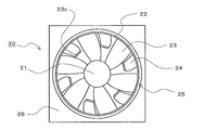
- FIG. 20 is a front view showing an example of a fan according to Embodiment 5 of the present invention.
- the fan 20 when the indoor unit 100 is planarly viewed in a state where the fan 20 is provided in the indoor unit 100 is a front view of the fan 20.
- the fan 20 according to the fifth embodiment is an axial fan, a diagonal fan, or the like in which a plurality of blades are provided on the outer peripheral surface of a boss that serves as a rotation center.
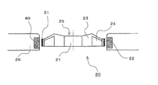
- the fan 20 includes an impeller 25 and a casing 26.
- the impeller 25 includes a boss 21 serving as a rotation center, a plurality of blades 23 (main blades) supported on the outer peripheral surface of the boss 21, and a ring-shaped member 22 provided on the outer peripheral side of the blade 23. Further, the impeller 25 according to the fifth embodiment includes a plurality of sub blades 24 supported by the ring-shaped member 22 toward the inner peripheral side (the boss 21 side). These sub blades 24 are not supported on the outer peripheral surface of the boss 21. As a result, the number of blades provided in the fan 20 (the number of blades 23 + the number of sub blades 24) is increased.
- a casing 26 is provided on the outer peripheral side of the impeller 25 through an outer peripheral portion of the impeller 25 and a predetermined gap. That is, the impeller 25 is housed in the housing 26.
- the boss 21 of the impeller 25 is connected to a fan motor 30 (not shown), and the impeller 25 rotates by the driving force of the fan motor.
- FIG. 21 is an explanatory diagram for explaining the relationship between the blade installation configuration (installation posture, number of installations, etc.) and aerodynamic performance.
- FIG. 21A is a front view showing a general impeller used for an axial flow fan and a mixed flow fan.
- FIG. 21B is a cross-sectional view of the blade row in which the cylindrical cross section at the position indicated by the alternate long and short dash line in FIG.
- the chord length L is a length of a straight line connecting the leading edge and the trailing edge of the blade 303.
- similar blade cascades having a constant chordal ratio ⁇ can obtain substantially the same aerodynamic performance. That is, it can be seen that in order to obtain the aerodynamic performance equal to that of a blade having a long chord length L with a blade having a short chord length L, the number of blades may be increased.
- the number of blades of the fan 20 (the impeller 25) is increased by the configuration shown in the fifth embodiment, it is not necessary to increase the number of blades supported by the boss 21.
- the sub blade 24 is connected to a portion other than the ring-shaped member 22, that is, the boss 21. For this reason, the chord length L can be shortened without reducing the air volume around the boss 21. Further, the blades 23 and the sub blades 24 do not need to change the angle of attack.
- the chord length L of the blade 23 in the range where the sub blade 24 is disposed can be shortened while maintaining the fan efficiency of the fan 20.
- the fan 20 can be reduced in thickness (reducing the dimension of the impeller 25 in the rotation axis direction) while maintaining fan efficiency.
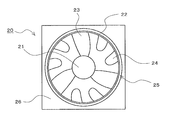
- FIG. 22 is a front view showing another example of a fan according to Embodiment 5 of the present invention.
- the fan 20 shown in FIG. 22 is provided with a protruding piece 23 a on the outer periphery of the blade 23.
- wing 24 is supported by this protrusion 23a toward the inner peripheral side (boss 21 side). That is, the fan 20 has a configuration in which the ring-shaped member 22 is divided into a plurality of parts.
- FIG. 23 is a front view showing still another example of the fan according to Embodiment 5 of the present invention.
- the fan 20 shown in FIGS. 20 and 22 was supported by members (ring-shaped member 22 and projecting piece 23a) provided on the blades 23.
- the sub blade 24 is directly supported by the blade 23.
- the sub blade 24 only needs to be supported by other than the boss 21. If the sub blade 24 is supported by other than the boss 21, the chord length L of the blade 23 in the range where the sub blade 24 is disposed can be shortened while maintaining the fan efficiency of the fan. For this reason, the fan 20 can be reduced in thickness (reducing the dimension of the impeller 25 in the rotation axis direction) while maintaining fan efficiency.
- Embodiment 6 FIG. As shown in the fifth embodiment, various configurations can be adopted as the configuration for supporting the sub blade 24. Among these, the structure which supports the sub blade
- items not particularly described are the same as those in the fifth embodiment, and the same functions and configurations are described using the same reference numerals.
- FIG. 24 is a longitudinal sectional view showing an example of a fan according to Embodiment 6 of the present invention.
- the sub blades 24 are supported by the ring-shaped member 22 similarly to the fan 20 shown in FIG. 20 of the fifth embodiment. That is, the outer peripheral part of each blade
- the centrifugal force acting on the blades 23 by the rotation of the impeller 25 is also supported by the ring-shaped member 22.
- wing 23 and a chord length can be made high.
- the shapes of the blades 23 and the sub blades 24 are different, but the shapes of the blades 23 and the sub blades 24 (more specifically, the shape excluding the joining portion) may be equal.
- Embodiment 7 the sub-blade 24 described in the fifth and sixth embodiments can be supported as follows.
- items not particularly described are the same as those in Embodiment 5 or Embodiment 6, and the same functions and configurations are described using the same reference numerals.
- FIG. 25 is a front view showing an example of a fan according to Embodiment 7 of the present invention.
- a ring-shaped member 23b is added to the fan 20 shown in FIG.
- the ring-shaped member 23b is provided so as to connect the substantially central portion of each blade 23.
- wing 24 is supported also by this ring-shaped member 23b in addition to the ring-shaped member 22 provided in the outer peripheral part of the blade
- the sub blade 24 can be supported at two locations, so that the vibration of the sub blade 24 can be suppressed and the strength of the sub blade 24 can be improved.
- FIG. 26 is a front view showing another example of a fan according to Embodiment 7 of the present invention.
- the fan 20 shown in FIG. 26 has a protruding piece 23c added to the fan 20 shown in FIG.
- the projecting piece 23 c is provided at a substantially central portion of each blade 23.
- wing 24 is supported also by this protrusion 23c in addition to the ring-shaped member 22 provided in the outer peripheral part of the blade
- the fan 20 shown in FIG. 22 may be provided with a ring-shaped member 23b and a protruding piece 23c, and the sub blade 24 may be supported at two locations.
- the fan 20 shown in FIG. 23 may be provided with the ring-shaped member 22 and the protruding piece 23a shown in the fifth embodiment and support the sub blades 24 at two locations.
- the sub blade 24 of the fan 20 shown in FIGS. 25 and 26 may be directly supported by the adjacent blade 23. By comprising in this way, the sub blade
- the sub blade 24 is supported at a plurality of locations. If the sub blade
- Embodiment 8 FIG.
- the number of blades 23 and sub blades 24 is the same, and they are alternately arranged in the rotation direction. Not only this but the blade
- items not particularly described are the same as those in the fifth to seventh embodiments, and the same functions and configurations are described using the same reference numerals.
- FIG. 27 is a front view showing an example of a fan according to Embodiment 8 of the present invention.
- the fan 20 shown in FIG. 27 has three sub blades 24 and six blades 23. When viewed in the rotational direction of the impeller 25, one sub blade 24 is provided after two blades 23 are provided. In the blades 23 and the sub blades 24, the interval between adjacent blades (interval in the circumferential direction) is substantially uniform.
- FIG. 28 is a front view showing another example of a fan according to Embodiment 8 of the present invention.
- the fan 20 shown in FIG. 28 has six sub blades 24, but three blades 23 are provided. When viewed in the rotational direction of the impeller 25, two sub blades 24 are provided after one blade 23 is provided. In the blades 23 and the sub blades 24, the interval between adjacent blades (interval in the circumferential direction) is substantially uniform.
- the number of the sub blades 24 is a divisor or a multiple of the number of the blades 23 and the interval (circumferential interval) between the blades 23 and the sub blades 24 is substantially uniform. It is possible to obtain an impeller capable of maintaining stable movement even during rotation and capable of stable operation.
- Embodiment 9 FIG.
- the externally driven fan motor 30 is connected to the boss 21 and the impeller 25 is rotated.
- the impeller 25 may be rotated by the fan motor 30 having the following configuration.
- items not particularly described are the same as those in the fifth to eighth embodiments, and the same functions and configurations are described using the same reference numerals.
- the fan motor 30 according to the ninth embodiment is adopted for the fan 20 shown in the sixth embodiment will be described.
- FIG. 29 is a longitudinal sectional view showing an example of a fan according to Embodiment 9 of the present invention.
- the fan 20 according to the ninth embodiment is different from the fan 20 shown in the sixth embodiment in the following points.
- the fan 20 according to the ninth embodiment is not provided with the externally driven fan motor 30 (the motor connected to the boss 21) provided in the fan 20 of the sixth embodiment.
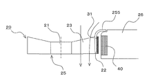
- the externally driven fan motor 30 instead of the externally driven fan motor 30, a fan motor 30 including a rotor 31 and a stator 40 described later is provided.
- the rotor 31 is provided on the outer peripheral portion of the impeller 25. Since the fan 20 according to the ninth embodiment is provided with the ring-shaped member 22 on the outer peripheral portion thereof, the rotor 31 is provided on the outer peripheral portion of the ring-shaped member 22.
- the stator 40 is provided (disposed) in the casing 26 so as to face the rotor 31.
- the impeller 25 is rotated by the driving force of the fan motor 30 including the rotor 31 and the stator 40.
- the fan 20 configured as described above does not require a pace for installing an externally driven fan motor. For this reason, it becomes possible to make the fan 20 thinner.
- the fan motor 30 can be configured at a location having a large diameter, it is easy to generate a large torque even when the equivalent magnetic attractive force is generated (equal motor power consumption). For this reason, it is possible to increase the efficiency at the same cost, or it is possible to obtain a small and inexpensive fan 20 by making it possible to configure a motor having the same performance with an inexpensive magnet or armature.
- the example in which the fan motor 30 according to the ninth embodiment is adopted for the fan 20 according to the sixth embodiment has been described.
- the fifth embodiment, the seventh embodiment, and the eighth embodiment are described.
- the fan motor 30 according to the ninth embodiment may be adopted as the fan 20 according to the above.
- Embodiment 10 FIG.
- the fan 20 When the fan 20 is provided with the ring-shaped member 22 or the like, for example, the fan 20 may be configured as in the tenth embodiment.
- the same functions and configurations as those in the first to ninth embodiments will be described using the same reference numerals.
- FIG. 30 is a schematic configuration diagram showing an example of a fan according to Embodiment 10 of the present invention.
- 30A is a front view of the fan
- FIG. 30B is a side sectional view of the fan.
- a fan 20 shown in FIG. 30 is an axial fan, a diagonal fan, or the like in which a plurality of blades 23 are provided on the outer peripheral surface of a boss 21 that serves as a rotation center.
- the fan 20 includes an impeller 25 and a casing 26.
- the impeller 25 includes a boss 21, a plurality of blades 23 provided on the outer peripheral surface of the boss 21, and a rotor 31 provided on the outer peripheral side of the blade 23.
- the rotor 31 is configured by providing a ring-shaped member 22 or the like on the outer peripheral side of the blade 23 and forming the ring-shaped member 22 from a magnetic material.
- the rotor 31 is configured by providing a ring-shaped member 22 or the like on the outer peripheral side of the blade 23 and attaching or embedding a magnet on the outer peripheral side of the ring-shaped member 22.
- the impeller 25 is housed in a casing 26.
- the casing 26 is provided with a stator 40 on a surface (hereinafter referred to as an inner peripheral portion) facing the outer peripheral side of the impeller 25 (more specifically, the outer peripheral side of the rotor 31). That is, the rotor 31 and the stator 40 are disposed to face each other.
- the impeller 25 is rotated by the driving force of the fan motor 30 constituted by the rotor 31 and the stator 40.
- the fan 20 shown in FIG. 30 is an example of the fan shown in the tenth embodiment of the present invention.
- the fan according to the tenth embodiment may be the following fan, for example.
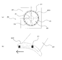
- FIG. 31 is a schematic configuration diagram showing another example of a fan according to Embodiment 10 of the present invention.
- FIG. 31 (a) is a front view of the fan
- FIG. 31 (b) is a perspective view showing the outer periphery of the fan blades.
- the arrow shown in FIG.31 (b) is a rotation direction of a blade
- the fan 20 shown in FIG. 31 is provided with a small blade 250 such as a winglet on the outer peripheral portion (outer peripheral end) of the blade 23.
- the rotor 31 is configured by forming the winglet 250 from a magnetic material. Further, for example, the rotor 31 is configured by attaching or embedding magnets on the outer peripheral side of the winglet 250.
- the fan 20 according to the tenth embodiment configured as described above is provided with a convex portion 251 in order to improve fan efficiency.
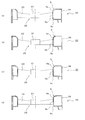
- FIG. 32 to FIG. 34 showing an installation example (formation example) of the convex portion 251, the fan 20 in which the ring-shaped member 22 is provided on the outer peripheral portion of the blade 23 will be described as an example.
- the convex portion 251 may be provided at a position on the air suction side.
- this convex part 251 may be provided in the outer peripheral part (for example, outer peripheral part of the ring-shaped member 22) of the impeller 25, as shown to Fig.32 (a).
- this convex part 251 may be provided in the inner peripheral part of the housing
- the convex portion 251 may be provided at a position on the air discharge side.
- this convex part 251 may be provided in the outer peripheral part (for example, outer peripheral part of the ring-shaped member 22) of the impeller 25, as shown to Fig.33 (a).
- this convex part 251 may be provided in the inner peripheral part of the housing
- 32 and 33 may be provided on both the outer peripheral portion of the impeller 25 (for example, the outer peripheral portion of the ring-shaped member 22) and the inner peripheral portion of the housing 26. That is, you may provide the convex part 251 provided in both so that it may mutually oppose.
- the convex portions 251 may be provided on both the air suction side and the air discharge side. Moreover, this convex part 251 may be provided in the outer peripheral part (for example, outer peripheral part of the ring-shaped member 22) of the impeller 25, as shown to Fig.34 (a). For example, this convex part 251 may be provided in the inner peripheral part of the housing
- the air suction side convex portion 251 may be provided on the outer peripheral portion of the impeller 25 (for example, the outer peripheral portion of the ring-shaped member 22), and the air discharge side convex portion 251 may be provided on the outer peripheral portion of the impeller 25.
- these formation positions may be reversed.
- the distance of the shortest portion between the impeller 25 and the housing 26 is made larger than the distance between the rotor 31 and the stator 40. Can be shortened. For this reason, the following effects can be acquired.
- the distance between the rotor and the stator is short (the gap formed between the rotor and the stator is preferably small).
- a conventional fan having a rotor on the outer periphery of the impeller and a stator on the housing side has a blade that is affected by the magnetic force generated between the rotor and the stator when the distance between the rotor and the stator is shortened.
- the car vibrates.
- noise is generated by this vibration. If the distance between the rotor and the stator is increased in order to prevent these vibrations and noises, an air flow that causes a decrease in fan efficiency is generated in the blade periphery.
- FIG. 35 is an explanatory diagram showing an example of an airflow that occurs in the periphery of the blades and causes a decrease in fan efficiency.
- the solid line arrow shown to Fig.35 (a) and FIG.35 (b) shows the flow direction of air.
- a white arrow shown in FIG. 35B indicates the rotation direction of the blade 303.
- the rotor and the stator When the distance between the two is increased, a leakage flow 253 as shown in FIG. 35B is generated, and the fan efficiency is lowered. More specifically, a leakage flow 253 is generated on the outer peripheral end side of the blade 303 from the high-pressure air discharge side to the low-pressure air suction side, and fan efficiency decreases.
- the fan 20 according to the tenth embodiment provides the convex portion 251 so that the distance of the shortest portion between the impeller 25 and the casing 26 is made larger than the distance between the rotor 31 and the stator 40. It is shortened. For this reason, the distance between the rotor 31 and the stator 40 can be a distance that can suppress the vibration of the impeller 25 and noise caused by the vibration. Moreover, the recirculation flow 252 and the leakage flow 253 can be suppressed by shortening the distance between the impeller 25 and the housing 26. That is, the fan 20 according to the tenth embodiment can increase the fan efficiency independently of the distance between the rotor 31 and the stator 40 which is a motor design matter.
- the sealing performance between the impeller 25 and the casing 26 is provided.
- the fan efficiency of the fan 20 can be further improved.
- the tip of the convex portion 251 shown in FIGS. 32 to 34 may have a labyrinth structure as shown in FIG.
- FIG. 36 shows a convex portion with a tip portion having a labyrinth structure as a convex portion 254.
- FIG. 36 shows an example in which the convex portion 254 is provided on the air discharge side of the impeller 25.
- the above-mentioned convex part 251 and convex part 254 may be provided continuously in the outer peripheral part of the impeller 25 and the inner peripheral part of the housing
- Embodiment 11 FIG. Even in the structure shown in the eleventh embodiment, the distance of the shortest portion between the impeller 25 and the casing 26 is shorter than the distance between the rotor 31 and the stator 40 as in the tenth embodiment. it can.
- items not particularly described are the same as those in the tenth embodiment, and the same functions and configurations are described using the same reference numerals.
- the ring-shaped member 22 and the small blades 250 are formed on the outer peripheral portion of the blade 23, and the rotor 31 is provided on the outer peripheral portion. That is, the basic configuration of the fan 20 is the same as the basic configuration of the fan 20 and the fan 20 according to the tenth embodiment.
- the fan 20 according to the eleventh embodiment replaces the convex portion 251 and the convex portion 254 shown in the tenth embodiment with at least one of the outer peripheral portion of the rotor 31 and the inner peripheral portion of the stator 40, such as resin.
- An insulating layer 257 is provided.
- the insulating layer 257 is provided as follows. The following FIG. 37 to FIG. 39 showing installation examples (formation examples) of the insulating layer 257 will be described by taking the fan 20 in which the ring-shaped member 22 is provided on the outer peripheral portion of the blade 23 as an example.
- the insulating layer 257 may be provided on the outer peripheral portion of the rotor 31.
- the insulating layer 257 may be provided on the inner peripheral portion of the stator 40.
- the insulating layer 257 may be provided on both the outer peripheral portion of the rotor 31 and the inner peripheral portion of the stator 40.
- the distance of the shortest portion between the impeller 25 and the casing 26 is set to be larger than the distance between the rotor 31 and the stator 40 as in the tenth embodiment. Can be shortened. For this reason, as in the tenth embodiment, the fan efficiency can be increased independently of the distance between the rotor 31 and the stator 40 which is a design matter of the motor.
- the distance of the shortest portion between the impeller 25 and the casing 26 is set to the rotor 31 without providing irregularities in the gap between the impeller 25 and the casing 26.
- the distance between the stator 40 and the stator 40 can be made shorter. For this reason, the assemblability at the time of manufacture improves and accumulation of dust etc. can be controlled.
- the insulating layer 257 on the inner peripheral portion of the stator 40 the coil wound around the stator 40 can be covered with the insulating layer 257 and the housing 26. By covering the uneven coil, accumulation of dust and the like can be further suppressed.
- Embodiment 12 FIG.
- the convex part provided in the outer peripheral part of the impeller 25 is good also as following structures. Note that in this twelfth embodiment, items that are not particularly described are the same as those in the tenth embodiment or the eleventh embodiment, and the same functions and configurations are described using the same reference numerals.
- FIG. 40 is an essential part enlarged view (longitudinal sectional view) showing an example of a fan according to Embodiment 12 of the present invention. Moreover, the solid line arrow shown in FIG. 40 shows the flow direction of air.
- an intake side guide 255 is provided on the intake side of the outer peripheral portion of the impeller 25.
- the intake side guide 255 is an example of a convex portion provided on the outer peripheral portion of the impeller 25, and is integrally formed with the ring-shaped member 22, for example.
- the front end portion of the intake side guide 255 has a shape protruding from the inner peripheral portion of the housing 26 to the outer peripheral side. Further, the intake side guide 255 has a shape whose diameter is increased toward the upstream side of the air flow. That is, the closest distance between the impeller 25 and the housing 26 is the distance in the rotation axis direction of the impeller 25. More specifically, the distance between the front end portion of the intake side guide 255 and the housing 26 is the closest distance between the impeller 25 and the housing 26. In FIG. 40, a stepped portion is formed in the casing 26 in a range facing the tip of the intake side guide 255.
- the distance of the shortest portion between the impeller 25 and the casing 26 is set between the rotor 31 and the stator 40 as in the tenth and eleventh embodiments. It can be shorter than the distance between. For this reason, as in the tenth and eleventh embodiments, the fan efficiency can be increased independently of the distance between the rotor 31 and the stator 40, which is a design matter of the motor.
- the airflow guided to the impeller 25 is smooth due to the shape of the intake side guide 255 whose diameter is increased toward the upstream side of the air flow. For this reason, the fan efficiency of the fan 20 is further improved.
- the fan 20 can be easily assembled even when the tip of the intake side guide 255 has a labyrinth structure. It becomes. Normally, when the impeller 25 is attached to the casing 26, the impeller 25 is inserted inside the casing 26 along the rotation axis direction of the impeller 25.
- Embodiment 13 The convex part provided in the outer peripheral part of the impeller 25 is good also as following structures.
- items that are not particularly described are the same as those in the tenth to twelfth embodiments, and the same functions and configurations are described using the same reference numerals.
- FIG. 41 is an enlarged view (longitudinal sectional view) showing a main part of an example of a fan according to Embodiment 13 of the present invention. Moreover, the solid line arrow shown in FIG. 41 shows the flow direction of air.
- a discharge-side guide 256 is provided on the discharge side of the outer peripheral portion of the impeller 25.
- the discharge side guide 256 is an example of a convex portion provided on the outer peripheral portion of the impeller 25, and is integrally formed with the ring-shaped member 22, for example.
- the distal end portion of the discharge side guide 256 has a shape protruding from the inner peripheral portion of the housing 26 to the outer peripheral side. Further, the discharge side guide 256 has a shape whose diameter is increased toward the downstream side of the air flow. That is, the closest distance between the impeller 25 and the housing 26 is the distance in the rotation axis direction of the impeller 25. More specifically, the distance between the distal end portion of the discharge side guide 256 and the housing 26 is the closest distance between the impeller 25 and the housing 26. In FIG. 41, a stepped portion is formed in the casing 26 in a range facing the tip end portion of the discharge side guide 256.
- the distance of the shortest portion between the impeller 25 and the casing 26 is set between the rotor 31 and the stator 40 as in the tenth to twelfth embodiments. It can be shorter than the distance between. For this reason, as in the tenth to twelfth embodiments, the fan efficiency can be increased independently of the distance between the rotor 31 and the stator 40, which is a design item of the motor.
- the air discharged from the impeller 25 decelerates while spreading in the radial direction due to the shape of the discharge-side guide 256 whose diameter is increased toward the downstream side of the air flow, Recover pressure. For this reason, the fan efficiency of the fan 20 is further improved.
- the fan efficiency of the fan 20 is further improved. Further, since the closest distance between the impeller 25 and the casing 26 is the distance in the rotation axis direction of the impeller 25, the fan 20 can be easily assembled even when the tip of the discharge side guide 256 has a labyrinth structure. It becomes. Normally, when the impeller 25 is attached to the casing 26, the impeller 25 is inserted inside the casing 26 along the rotation axis direction of the impeller 25.
- Embodiment 14 By causing the casing 26 of the fan 20 to function as a silencer mechanism, noise generated from the fan 20 can be reduced. In addition, by making the housing 26 of the fan 20 function as a silencer mechanism, it is possible to reduce noise generated from the motor stay. Therefore, the silencing effect of the indoor unit can be further improved by combining with the motor stay structure shown in the second to fourth embodiments. In the fourteenth embodiment, the same functions and configurations as those in the first to thirteenth embodiments are described using the same reference numerals.
- FIG. 42 is a longitudinal sectional view of a fan according to Embodiment 14 of the present invention.
- the casing 26 of the fan 20 according to the fourteenth embodiment is divided into an upper casing 26a and a lower casing 26b.
- the upper housing 26 a is composed of an upper surface portion of the housing 26, an upper portion 5 a of the bell mouth 5, and a central portion 5 b of the bell mouth 5.
- the lower housing 26 b includes an outer peripheral portion of the housing 26, a bottom surface portion of the housing 26, and a lower portion 5 c of the bell mouth 5.
- the inside of the housing 26 has a hollow structure.
- a gap having a length l is formed between the central portion 5b and the lower portion 5c of the bell mouth 5.
- This gap communicates with the inside of the housing 26, and is formed along the circumferential direction of the bell mouth 5, for example. That is, in the fourteenth embodiment, the gap having the length l has a slit shape.
- the fan 20 reduces the noise of the fan 20 (rotation sound of the impeller 25) by making the casing 26 have a hollow structure and functioning as a Helmholtz type silencer.
- f (a / 2 ⁇ ) ⁇ (A / l ⁇ V) 1/2 ... 2
- f noise frequency
- a sound velocity
- A gap area (that is, in the fourteenth embodiment, the length of the gap l ⁇ the circumferential length of the central portion 5b of the bell mouth 5)
- l the gap
- V the volume of the space in the housing 26.
- FIG. 43 is a front sectional view showing another example of a fan according to Embodiment 14 of the present invention.
- the inside of the housing 26 of the fan 20 is divided into a plurality of spaces (four spaces in FIG. 43) by the ribs 26c.
- V in the above equation 2 By varying the volume of these spaces (V in the above equation 2), it becomes possible to mute noises of more frequencies at the same time. It is also possible to adjust the frequency to be silenced by adjusting the length l of the gap communicating with each space shown in FIG.
- a gap (gap having a length l) communicating with the casing 26 is formed between the central part 5b and the lower part 5c of the bell mouth 5, but this gap (gap having a length l) is formed.
- a gap communicating with the housing 26 may be formed between the upper portion 5a and the central portion 5b of the bell mouth 5.
- the central portion 5b of the bell mouth 5 may be divided, and a gap (gap having a length l) communicating with the housing 26 may be formed between the divided central portions 5b.
- a plurality of gaps such as between the upper part 5a and the central part 5b of the bell mouth 5 and between the central part 5b and the lower part 5c of the bell mouth 5 may be formed.
- the housing 26 of the fan 20 in order for the housing 26 of the fan 20 to function as a Helmholtz-type silencer, it is only necessary to have a communication path communicating with the inside of the housing 26.
- the fan 20 may be configured as shown in FIG.
- FIG. 44 is a longitudinal sectional view showing still another example of a fan according to Embodiment 14 of the present invention.
- the fan 20 shown in FIG. 44 has a plurality of through-holes 5 d communicating with the internal space of the housing 26 formed in the central portion 5 b of the bell mouth 5, instead of the gap of length l communicating with the housing 26. .
- the housing 26 of the fan 20 can function as a Helmholtz-type silencer.
- the pressure fluctuation generated by the fan 20 can be reduced by forming the communication passage communicating with the inside of the housing 26 with a plurality of through holes, the noise generated from the fan 20 can be further reduced.
- the bell mouth 5 may be formed of a porous material.
- the space in the casing 26 may be divided by ribs 26c as shown in FIG. With this configuration, the volume of the space formed in the housing 26 can be increased, and noise in the low frequency region can be silenced.
- Embodiment 15 FIG.
- the fan 20 can be configured as in the fifteenth embodiment to improve the blowing performance of the fan 20.
- items not particularly described are the same as those in the fourteenth embodiment, and the same functions and configurations are described using the same reference numerals.
- FIG. 46 is a longitudinal sectional view showing a fan according to Embodiment 15 of the present invention.
- the fan 20 according to the fifteenth embodiment at least a part of the bell mouth 5 is integrally formed with the blade 23 of the impeller 25.
- wing 23 of the impeller 25 is not specifically limited.
- the central portion 5b of the bell mouth 5 and the blades 23 of the impeller 25 may be integrally formed.
- the upper portion 5a and the central portion 5b of the bell mouth 5 and the blades 23 of the impeller 25 may be integrally formed.
- FIG. 46A the central portion 5b of the bell mouth 5 and the blades 23 of the impeller 25 may be integrally formed.
- the upper portion 5a and the central portion 5b of the bell mouth 5 and the blades 23 of the impeller 25 may be integrally formed.
- the central portion 5b and the lower portion 5c of the bell mouth 5 and the blades 23 of the impeller 25 may be integrally formed. Further, for example, as shown in FIG. 46 (d), the entire bell mouth 5 (upper part 5a, central part 5b and lower part 5c) and the blades 23 of the impeller 25 may be integrally formed.
- the fan 20 By configuring the fan 20 in this way, it is possible to prevent leakage flow (flow from the blade pressure surface side to the blade suction surface side) generated in the gap between the blade 23 of the impeller 25 and the bell mouth 5. For this reason, the pressure difference of the suction inlet side and the blower outlet side of the fan 20 can be maintained, and the improvement of ventilation performance can be aimed at. Further, since noise generated from the fan 20 is reduced by preventing leakage flow and the like, in addition to the silencing effect obtained by causing the casing 26 of the fan 20 to function as a Helmholtz type silencer, a further silencing effect can be obtained. You can also.
- Embodiment 16 When the casing 26 of the fan 20 functions as a Helmholtz type silencer, the space in the casing 26 can be effectively used as follows.
- items that are not particularly described are the same as those in the fourteenth or fifteenth embodiment, and the same functions and configurations are described using the same reference numerals.
- FIG. 47 is a longitudinal sectional view showing a fan according to Embodiment 16 of the present invention.
- a circuit board 30a and a noise detection microphone 161 of a silencing mechanism are installed in a space inside the casing 26.
- the circuit board 30a is, for example, a circuit board on which a circuit for controlling the fan motor 30 and the like are mounted.
- the space efficiency inside the indoor unit 100 is improved, the indoor unit can be downsized and the air path loss can be reduced, and the power efficiency can be improved.
- casing 26 function as a Helmholtz type silencer, it is not necessary to provide the communication path connected to the space in the housing
- the noise detection microphone 161 detects the noise of the fan 20 transmitted through the housing 26, the noise generated by the fan 20 by the active silencing method described in the first embodiment can be reduced. In this case, it can be said that the housing 26 functions as a part of an active silencing mechanism.
- what is installed in the space inside the casing 26 is not limited to the circuit board 30a and the noise detection microphone 161, and may be a temperature measurement sensor, for example.
- Embodiment 17 when making the housing
- items not particularly described are the same as those in the fourteenth to sixteenth embodiments, and the same functions and configurations are described using the same reference numerals.
- FIG. 48 is a longitudinal sectional view showing a fan according to Embodiment 17 of the present invention.
- the fan 20 according to the seventeenth embodiment is provided with a sound absorbing material 260 in the space inside the housing 26.
- the sound absorbing material 260 is made of, for example, urethane, porous resin, porous aluminum, or the like.
- the pressure fluctuation generated by the fan 20 is absorbed by the sound absorbing material 260.
- the silencing effect obtained by causing the housing 26 of the fan 20 to function as a Helmholtz type silencer the silencing effect that the noise generated in the wide band by the sound absorbing material 260 can also be reduced is obtained.
- Embodiment 18 FIG. By providing fan 20 shown in Embodiments 5 to 17 in indoor unit 100 shown in Embodiment 1, the following effects can be obtained.
- FIG. 49 is a longitudinal sectional view showing an indoor unit according to Embodiment 18 of the present invention.
- FIG. 49 shows an example in which the fan 20 shown in any of the fifth to seventeenth embodiments is used in the indoor unit 100.
- 49 shows the left side of the drawing as the front side of the indoor unit 100.
- the fan 20 that can be downsized (thinned) and reduced in cost is used. For this reason, the indoor unit 100 according to Embodiment 18 can be reduced in size (thinned). In addition, the cost of the indoor unit 100 can be reduced. Moreover, in the indoor unit 100 configured as described above, the fan 20 is used which is reduced in size (thinned) while maintaining fan efficiency. For this reason, when an indoor unit of the same size is manufactured, an indoor unit having a larger air volume than a conventional indoor unit can be obtained.
- Embodiment 19 FIG. ⁇ Individual fan control>
- the indoor unit 100 according to the present invention includes the plurality of fans 20. By controlling each of these fans 20 individually, the wind direction controllability of the indoor unit 100 can be improved.
- the nineteenth embodiment an example of a specific embodiment for individually controlling the air volume of each fan 20 will be described.
- an indoor unit 100 in which three fans 20 are arranged side by side along the left-right direction (longitudinal direction) of the casing 1 will be described as an example.
- the fans 20 ⁇ / b> A, 20 ⁇ / b> B, and 20 ⁇ / b> C are referred to in order from the left side of the casing 1.
- the same reference numerals are used to describe the same functions and configurations as those in the first to eighteenth embodiments.
- the invention shown in the nineteenth embodiment is also established when the number of fans arranged in parallel in the indoor unit 100 is other than three.
- FIG. 50 is an explanatory diagram showing an example of the wind speed distribution at the air outlet in the indoor unit according to Embodiment 19 of the present invention.
- FIG. 50 shows a front view of the indoor unit 100.
- the indoor unit 100 according to Embodiment 19 is provided with three fans 20 in the left-right direction (longitudinal direction) of the casing 1.
- the wind speed distribution at the outlet 3 of the indoor unit 100 becomes as shown by the arrow in FIG. That is, assuming that the air volume of the fans 20A to 20C is fan 20A ⁇ fan 20B ⁇ fan 20C, the wind speed distribution at the outlet 3 of the indoor unit 100 is as shown by the arrow in FIG.
- the direction of the arrow shown in FIG. 50 shows the direction of airflow
- size of the arrow of FIG. 50 has shown the magnitude
- FIG. 51 is an explanatory diagram showing another example of the wind speed distribution at the air outlet in the indoor unit according to Embodiment 19 of the present invention.
- FIG. 51 shows a front view of the indoor unit 100.
- the wind speed distribution at the outlet 3 of the indoor unit 100 becomes as shown by the arrow in FIG. That is, if the air volume of the fans 20A to 20C is fan 20A> fan 20B> fan 20C, the wind speed distribution at the outlet 3 of the indoor unit 100 is as shown by the arrow in FIG.
- the direction of the arrow shown in FIG. 51 shows the direction of the air flow
- the size of the arrow in FIG. 51 shows the size of the wind speed. That is, the arrow in FIG. 51 indicates that the longer the length, the faster the wind speed (in other words, the greater the air volume).
- FIG. 52 is an essential part enlarged view (front sectional view) showing the vicinity of the air outlet of the indoor unit according to Embodiment 19 of the present invention.
- FIG. 52 shows the left and right vanes 80 when the airflow blown from the outlet 3 is controlled in the right direction of FIG.
- the airflow bent by the left and right vanes 80 collides with the side wall portion of the casing 1 in the vicinity of the air outlet 3, resulting in ventilation loss.
- the total air volume of the air outlet 3 is set to the same air volume as that of a conventional indoor unit (an indoor unit in which only one fan is provided or an indoor unit in which each of the plurality of fans is not controlled), By individually controlling the air volume of each fan 20, it is possible to reduce a ventilation loss caused by an air current colliding with the side wall portion of the casing 1.
- the difference of the air volume of the adjacent fans 20 is about 20% or less. It was found that there is little influence on the heat exchange performance. Further, it was found that if the difference in the air volume between adjacent fans 20 is about 10% or less, the influence on the heat exchange performance is further reduced. For this reason, when the air volume is individually controlled for each fan 20, the difference in the air volume between adjacent fans 20 is preferably about 20% or less. Further, when the air volume is individually controlled for each fan 20, it is more preferable that the difference in air volume between adjacent fans 20 is about 10% or less.
- the effect of individually controlling the air volume of each fan 20 is not limited to the above-described ventilation loss reduction effect.
- the air volume of each fan 20 may be individually controlled so that the airflow reaching this place increases.
- the airflow reaching this place increases.
- you want to avoid air-conditioning airflow when performing windbreak mild air-conditioning
- make sure that the airflow reaching this place is small (or that airflow does not reach this place) What is necessary is just to control the air volume of the fan 20 separately.
- a plurality of fans 20 having the same shape (same specifications) are provided, and the air volume of each fan 20 is individually controlled by changing the rotation speed of each fan 20.
- “the product of the number of blades 23 of the fan 20 and the number of rotations of the impeller 25 of the fan 20” may be separated by about 10 Hz for each fan 20.
- Embodiment 20 FIG. Further, the air volume of each fan 20 may be individually controlled as follows.
- items that are not particularly described are the same as those in the nineteenth embodiment, and the same functions and configurations are described using the same reference numerals.
- FIG. 53 is an explanatory diagram showing the wind speed distribution at the outlet when the air volume of each fan 20 is the same in the indoor unit according to Embodiment 20 of the present invention.
- FIG. 53 shows a front view of the indoor unit 100. 53 indicates the direction of airflow, and the size of the arrow in FIG. 53 indicates the size of the wind speed. That is, the arrow in FIG. 53 indicates that the longer the length, the faster the wind speed (in other words, the greater the air volume).
- FIG. 53 it can be seen that when the air volume generated by each fan 20 is the same, the wind speed decreases in the vicinity of both ends of the air outlet 3. This is because the wind speed is reduced by the airflow friction generated at the side wall of the casing 1 constituting the air passage.
- the indoor unit 100 when the indoor unit 100 is operated in the low air volume (low capacity) mode, the air volume of each fan 20 is controlled as shown in FIG.
- FIG. 54 is an explanatory diagram showing an example of the wind speed distribution at the outlet when the indoor unit according to Embodiment 20 of the present invention operates in the low air volume mode.
- the indoor unit 100 according to Embodiment 20 When operating in the low air volume (low capacity) mode, the indoor unit 100 according to Embodiment 20 has a fan 20A and a fan 20C arranged at both ends so that the wind speed in the vicinity of both ends of the air outlet 3 is increased. Is larger than the air volume of the fan 20B arranged in the center.
- the difference of the air volume of the adjacent fans 20 is about 20% or less. It was found that there is little influence on the heat exchange performance. Further, it was found that if the difference in the air volume between adjacent fans 20 is about 10% or less, the influence on the heat exchange performance is further reduced. For this reason, when the air volume is individually controlled for each fan 20, the difference in the air volume between adjacent fans 20 is preferably about 20% or less. Further, when the air volume is individually controlled for each fan 20, it is more preferable that the difference in air volume between adjacent fans 20 is about 10% or less.
- the air volume of each fan 20 is further individually increased so that the airflow reaching this place is increased. You may control to. Also, for example, if there is a place where you want to avoid air-conditioning airflow (when performing windbreak mild air-conditioning), make sure that the airflow reaching this place is small (or that airflow does not reach this place)
- the air volume of the fan 20 may be further individually controlled.
- each fan 20 The silencing effect is further improved by combining the configuration for individually controlling the air volume with these silencing mechanisms.
- an active silencing mechanism is provided in the indoor unit 100, it is preferable to provide a silencing mechanism according to the number of sound sources (the number of fans 20).
- a silencer mechanism corresponding to the number of sound sources cannot be provided due to restrictions on dimensions and costs of the indoor unit 100. Even in such a case, a sufficient silencing effect can be obtained by combining the configurations for individually controlling the air volume of each fan 20.
- FIG. 55 is a characteristic diagram showing the relationship between the air volume reduction rate of the central fan and the noise reduction effect at the same air volume in the indoor unit according to Embodiment 20 of the present invention.
- FIG. 55 shows the amount of noise reduction when the air volume of the fan 20B arranged in the center is reduced with the same total air volume of the air outlet 3. Further, -1 dB, -2 dB, -3 dB, -4 dB, and -5 dB shown in FIG. 55 are noise reduction effects with respect to noise that is most relevant to the sound detected by the noise reduction detection device.
- the noise detection microphone 161 and the control speaker of the silencing mechanism used to obtain the result of FIG.
- ⁇ 1 dB, ⁇ 2 dB, ⁇ 3 dB, ⁇ 4 dB, and ⁇ 5 dB shown in FIG. 55 indicate the silencing effect on the noise emitted by the fan 20A and the fan 20C.
- the entire indoor unit 100 can provide a silencing effect of 2.7 dB in total.
- the air volume of the central fan 20B is reduced by about 15% as shown in the present embodiment 20, in order to obtain the same air volume, the fan 20A and the fan 20B arranged in the vicinity of both ends are respectively Increase 7.5% airflow.
- the noise radiated by the fan 20A and the fan 20B disposed in the vicinity of both ends increases by 1.9 dB, and the noise radiated from the fan 20B disposed in the center is 2 dB reduction.
- the overall indoor unit 100 can obtain a noise reduction effect of 3.5 dB in total, and the noise reduction effect is improved as compared to before the air volume of each fan 20 is individually controlled.
- a plurality of fans 20 having the same shape (same specifications) are provided, and the air volume of each fan 20 is individually controlled by changing the rotation speed of each fan 20.
- “the product of the number of blades 23 of the fan 20 and the number of rotations of the impeller 25 of the fan 20” may be separated by about 10 Hz for each fan 20.
- Embodiment 21 FIG. Further, the air volume of each fan 20 may be individually controlled as follows.
- items that are not particularly described are the same as those in Embodiment 19 or Embodiment 20, and the same functions and configurations are described using the same reference numerals.
- FIG. 56 is an explanatory diagram showing an example of the wind speed distribution at the air outlet in the indoor unit according to Embodiment 21 of the present invention.
- FIG. 56 shows a front view of the indoor unit 100.
- 56 indicates the direction of airflow
- the size of the arrow in FIG. 56 indicates the size of the wind speed. That is, the arrow in FIG. 56 indicates that the longer the length, the faster the wind speed (in other words, the greater the air volume).
- the air volume of fan 20B arranged at the center is arranged at both ends so that the wind speed at the center of blower outlet 3 is larger than the wind speed near both ends. It is larger than the air volume of the fan 20A and the fan 20C.
- the airflow blown out from the air outlet 3 gradually loses velocity energy where it comes into contact with the low speed or stop air in the room, and finally the velocity at the center of the airflow is reduced.
- the air flow blown out from the air outlet 3 is made to be the same as that of the twenty-first embodiment, so that the flow velocity at the central portion of the air flow when the same air volume is generated is changed to the conventional indoor unit (the room provided with only one fan). Or an indoor unit that does not control the air volume of each of the plurality of fans), and airflow reachability can be improved.
- the difference of the air volume of the adjacent fans 20 is about 20% or less. It was found that there is little influence on the heat exchange performance. Further, it was found that if the difference in the air volume between adjacent fans 20 is about 10% or less, the influence on the heat exchange performance is further reduced. For this reason, when the air volume is individually controlled for each fan 20, the difference in the air volume between adjacent fans 20 is preferably about 20% or less. Further, when the air volume is individually controlled for each fan 20, it is more preferable that the difference in air volume between adjacent fans 20 is about 10% or less.
- the air volume of each fan 20 is further individually increased so that the airflow reaching this place is increased. You may control to. Also, for example, if there is a place where you want to avoid air-conditioning airflow (when performing windbreak mild air-conditioning), make sure that the airflow reaching this place is small (or that airflow does not reach this place)
- the air volume of the fan 20 may be further individually controlled.
- a plurality of fans 20 having the same shape (same specifications) are provided, and the air volume of each fan 20 is individually controlled by changing the rotation speed of each fan 20.
- “the product of the number of blades 23 of the fan 20 and the number of rotations of the impeller 25 of the fan 20” may be separated by about 10 Hz for each fan 20.
- Embodiment 22 FIG.
- a plurality of fans 20 having the same shape (same specifications) are provided, and the air volume of each fan 20 is individually controlled by changing the rotation speed of each fan 20.
- the present invention is not limited to this, and the same effects as those of the nineteenth to twenty-first embodiments can be obtained by using a fan 20 having a different blowing capacity (for example, a fan 20 having a different fan diameter, boss ratio, blade attachment angle, etc.).
- the use of a plurality of fans 20 with different blowing capacities improves the mounting density of the fans 20 and allows more detailed control of the wind speed distribution inside the indoor unit 100 (casing 1). The effect which was not acquired can also be acquired further.
- the difference in air volume between adjacent fans 20 is about 20% or less (more preferably 10% or less) to prevent the heat exchange performance from deteriorating, and “the number of blades 23 of the fan 20 and the impeller of the fan 20 It is effective to use the fans 20 having different numbers of blades 23 in order to achieve both of preventing the beat noise by separating the product of the rotational speed of 25 by about 10 Hz in each fan 20.
- Embodiment 23 FIG. ⁇ Heat exchanger>
- the fan 20 is disposed on the upstream side of the heat exchanger 50.
- production of a wind speed are suppressed compared with the indoor unit of the conventional air conditioner in which the fan is provided in the blower outlet. Therefore, the shape of the heat exchanger 50 is not limited to the shape shown in the first embodiment, and may be the following shape, for example.
- the same functions and configurations as those in the first to twenty-second embodiments are described using the same reference numerals.
- FIG. 57 is a longitudinal sectional view showing an indoor unit according to Embodiment 23 of the present invention.
- a heat exchanger 50 that is not divided into the front-side heat exchanger 51 and the rear-side heat exchanger 55 is provided on the downstream side of the fan 20.
- the air that has passed through the filter 10 flows into the fan 20.
- the air flowing into the fan 20 is less disturbed than the air flowing into the conventional indoor unit (passed through the heat exchanger).
- the indoor unit 100 according to Embodiment 23 can suppress noise as compared with the conventional indoor unit.
- the fan 20 is provided in the upstream of the heat exchanger 50, the indoor unit 100 is blown out from the blower outlet 3, compared with the indoor unit of the conventional air conditioner in which the fan is provided in the blower outlet.
- the generation of the swirling air flow and the generation of the wind speed distribution can be suppressed.
- there is no complicated structure such as a fan at the air outlet 3 it is easy to take measures against dew condensation caused by backflow or the like.
- Embodiment 24 By configuring the heat exchanger 50 with the front side heat exchanger 51 and the back side heat exchanger 55, it becomes possible to further suppress noise than the indoor unit 100 according to the twenty-third embodiment.
- the shape is not limited to the shape of the heat exchanger 50 shown in the first embodiment, and for example, the shape can be as follows.
- the twenty-fourth embodiment differences from the above-described twenty-third embodiment will be mainly described, and the same parts as those in the twenty-third embodiment are denoted by the same reference numerals.
- FIG. 58 is a longitudinal sectional view showing the indoor unit according to Embodiment 24 of the present invention.
- the front-side heat exchanger 51 and the back-side heat exchanger 55 constituting the heat exchanger 50 are separated by a symmetric line 50a in the right vertical section.
- the symmetry line 50a divides the installation range of the heat exchanger 50 in this cross section in the left-right direction at a substantially central portion. That is, the front side heat exchanger 51 is arranged on the front side (left side of the drawing) with respect to the symmetry line 50a, and the rear side heat exchanger 55 is arranged on the back side (right side of the drawing) with respect to the symmetry line 50a.
- the front-side heat exchanger 51 and the rear-side heat exchanger 55 are arranged so that the distance between the front-side heat exchanger 51 and the rear-side heat exchanger 55 is narrow with respect to the air flow direction, that is, the right-side longitudinal section. It is arrange
- the front side heat exchanger 51 and the back side heat exchanger 55 are arranged so as to be inclined with respect to the flow direction of the air supplied from the fan 20. Furthermore, the air path area of the back surface side heat exchanger 55 is characterized by being larger than the air path area of the front surface side heat exchanger 51.
- the longitudinal length of the back side heat exchanger 55 is longer than the longitudinal direction length of the front side heat exchanger 51 in the right vertical section. Thereby, the air path area of the back surface side heat exchanger 55 is larger than the air path area of the front surface side heat exchanger 51.
- the other configurations of the front side heat exchanger 51 and the back side heat exchanger 55 are the same. That is, the heat transfer area of the back side heat exchanger 55 is larger than the heat transfer area of the front side heat exchanger 51.
- the rotating shaft 20a of the fan 20 is installed above the symmetry line 50a.
- the fan 20 is provided on the upstream side of the heat exchanger 50, the same effect as in the twenty-third embodiment can be obtained.
- an amount of air according to the air passage area passes through each of the front side heat exchanger 51 and the back side heat exchanger 55. That is, the air volume of the back side heat exchanger 55 is larger than the air volume of the front side heat exchanger 51. And when the air which passed each of the front side heat exchanger 51 and the back side heat exchanger 55 merges by this air volume difference, this merged air will bend to the front side (blower outlet 3 side).
- the indoor unit 100 according to Embodiment 24 can further suppress noise compared to the indoor unit 100 according to Embodiment 23. Moreover, since the indoor unit 100 which concerns on this Embodiment 24 can reduce the pressure loss in the blower outlet 3 vicinity, it also becomes possible to reduce power consumption.
- the heat exchanger 50 shown in FIG. 58 is comprised by the substantially V shape by the front side heat exchanger 51 and the back side heat exchanger 55 which were formed separately, it is not limited to this structure.
- the front-side heat exchanger 51 and the back-side heat exchanger 55 may be configured as an integrated heat exchanger (see FIG. 67).
- each of the front side heat exchanger 51 and the back side heat exchanger 55 may be configured by a combination of a plurality of heat exchangers (see FIG. 67).
- the front side becomes the front side heat exchanger 51 and the rear side becomes the back side heat exchanger 55 with respect to the symmetry line 50a.
- the length in the longitudinal direction of the heat exchanger disposed on the back side of the symmetry line 50a may be longer than the length of the heat exchanger disposed on the front side of the symmetry line 50a.
- the longitudinal lengths of the plurality of heat exchangers constituting the front side heat exchanger 51 are each. Is the length of the front side heat exchanger 51 in the longitudinal direction.
- the sum of the longitudinal lengths of the plurality of heat exchangers constituting the back side heat exchanger 55 is the longitudinal length of the back side heat exchanger 55.
- the heat exchanger 50 is composed of a plurality of heat exchangers (for example, when the heat exchanger 50 is composed of the front side heat exchanger 51 and the back side heat exchanger 55), the location where the arrangement gradient of the heat exchanger 50 changes ( For example, the heat exchangers do not have to be in complete contact with each other at a substantial connection point between the front-side heat exchanger 51 and the back-side heat exchanger 55, and there may be some gaps.
- the shape of the heat exchanger 50 in the right-side vertical cross section may be a part or all of a curved shape (see FIG. 67).
- FIG. 67 is a schematic diagram for explaining a configuration example of the heat exchanger 50.
- FIG. 67 shows the heat exchanger 50 as seen from the right vertical cross section.
- the overall shape of the heat exchanger 50 shown in FIG. 67 is substantially ⁇ type, but the overall shape of the heat exchanger is merely an example.
- the heat exchanger 50 may be composed of a plurality of heat exchangers.
- the heat exchanger 50 may be configured as an integrated heat exchanger.
- you may comprise the heat exchanger which comprises the heat exchanger 50 by a some heat exchanger further.
- a part of the heat exchanger constituting the heat exchanger 50 may be arranged vertically.
- the shape of the heat exchanger 50 may be a curved shape.
- Embodiment 25 Embodiment 25.
- FIG. Moreover, the heat exchanger 50 may be configured as follows. In the twenty-fifth embodiment, differences from the above-described twenty-fourth embodiment will be mainly described, and the same parts as those in the twenty-fourth embodiment are denoted by the same reference numerals.
- FIG. 59 is a longitudinal sectional view showing an indoor unit according to Embodiment 25 of the present invention.
- the indoor unit 100 according to the twenty-fifth embodiment is different from the indoor unit 100 according to the twenty-fourth embodiment in the manner in which the heat exchanger 50 is arranged.
- the heat exchanger 50 includes three heat exchangers, and each heat exchanger has a different inclination with respect to the flow direction of the air supplied from the fan 20. Has been placed. And the heat exchanger 50 is a substantially N type in the right side longitudinal cross-section.
- the heat exchanger 51a and the heat exchanger 51b arranged on the front side of the symmetry line 50a constitute the front side heat exchanger 51
- the heat exchanger 55b constitutes the back side heat exchanger 55. That is, in the twenty-fifth embodiment, the heat exchanger 51b and the heat exchanger 55b are configured as an integrated heat exchanger.
- the symmetry line 50a divides the installation range of the heat exchanger 50 in the right vertical section in the left-right direction at a substantially central portion.
- the length of the rear side heat exchanger 55 in the longitudinal direction is longer than the length of the front side heat exchanger 51 in the longitudinal direction. That is, the air volume of the back side heat exchanger 55 is larger than the air volume of the front side heat exchanger 51.
- the comparison of the lengths is the sum of the lengths of the heat exchanger groups constituting the front-side heat exchanger 51 and the sum of the lengths of the heat exchanger groups constituting the back-side heat exchanger 55. Should be compared.
- the air volume of the rear side heat exchanger 55 is larger than the air volume of the front side heat exchanger 51. For this reason, when the air which passed each of the front side heat exchanger 51 and the back side heat exchanger 55 merges by air volume difference similarly to Embodiment 24, this merged air is the front side (blower 3 To the side). For this reason, it is no longer necessary to bend the airflow rapidly in the vicinity of the outlet 3, and the pressure loss in the vicinity of the outlet 3 can be reduced. Therefore, the indoor unit 100 according to Embodiment 25 can further suppress noise compared to the indoor unit 100 according to Embodiment 23. Moreover, since the indoor unit 100 can reduce the pressure loss in the vicinity of the blower outlet 3, it also becomes possible to reduce power consumption.
- the shape of the heat exchanger 50 substantially N-shaped in the right vertical section, it is possible to increase the area through which the front-side heat exchanger 51 and the back-side heat exchanger 55 pass.
- the wind speed can be made smaller than that in the twenty-fourth embodiment. For this reason, compared with Embodiment 24, the pressure loss in the front side heat exchanger 51 and the back side heat exchanger 55 can be reduced, and further reduction in power consumption and noise can be achieved.
- the heat exchanger 50 shown in FIG. 59 is comprised by the substantially N type by the three heat exchangers formed separately, it is not limited to this structure.
- the three heat exchangers constituting the heat exchanger 50 may be configured as an integrated heat exchanger (see FIG. 67).
- each of the three heat exchangers constituting the heat exchanger 50 may be configured by a combination of a plurality of heat exchangers (see FIG. 67).
- the front side becomes the front side heat exchanger 51 and the rear side becomes the back side heat exchanger 55 with respect to the symmetry line 50a.
- the length in the longitudinal direction of the heat exchanger disposed on the back side of the symmetry line 50a may be longer than the length of the heat exchanger disposed on the front side of the symmetry line 50a.
- the longitudinal lengths of the plurality of heat exchangers constituting the front side heat exchanger 51 are each. Is the length of the front side heat exchanger 51 in the longitudinal direction.
- the sum of the longitudinal lengths of the plurality of heat exchangers constituting the back side heat exchanger 55 is the longitudinal length of the back side heat exchanger 55.
- the heat exchanger 50 it is not necessary to incline all the heat exchangers constituting the heat exchanger 50 in the right vertical section, and a part of the heat exchangers constituting the heat exchanger 50 may be arranged vertically in the right vertical section. (See FIG. 67). Further, when the heat exchanger 50 is constituted by a plurality of heat exchangers, it is not necessary that the heat exchangers are completely in contact with each other at a place where the arrangement gradient of the heat exchanger 50 changes, and there is a slight gap. May be. Moreover, the shape of the heat exchanger 50 in the right-side vertical cross section may be a part or all of a curved shape (see FIG. 67).
- Embodiment 26 Embodiment 26.
- the heat exchanger 50 may be configured as follows. In the twenty-sixth embodiment, the differences from the twenty-fourth and twenty-fifth embodiments described above will be mainly described. is doing. Moreover, the case where the indoor unit is a wall-mounted type attached to the wall surface of the air-conditioning target area is shown as an example.
- FIG. 60 is a longitudinal sectional view showing an indoor unit according to Embodiment 26 of the present invention.
- the indoor unit 100 according to the twenty-sixth embodiment is different from the indoor units shown in the twenty-fourth and twenty-fifth embodiments in the manner in which the heat exchanger 50 is arranged.
- the heat exchanger 50 includes four heat exchangers, and each of these heat exchangers is disposed with a different inclination with respect to the flow direction of the air supplied from the fan 20.
- the heat exchanger 50 is substantially W-shaped in the right vertical section.
- the heat exchanger 51a and the heat exchanger 51b arranged on the front side of the symmetry line 50a constitute the front side heat exchanger 51
- the heat exchanger 55b constitutes the back side heat exchanger 55.
- the symmetry line 50a divides the installation range of the heat exchanger 50 in the right vertical section in the left-right direction at a substantially central portion.
- the length of the rear side heat exchanger 55 in the longitudinal direction is longer than the length of the front side heat exchanger 51 in the longitudinal direction. That is, the air volume of the back side heat exchanger 55 is larger than the air volume of the front side heat exchanger 51.
- the comparison of the lengths is the sum of the lengths of the heat exchanger groups constituting the front-side heat exchanger 51 and the sum of the lengths of the heat exchanger groups constituting the back-side heat exchanger 55. Should be compared.
- the air volume of the rear side heat exchanger 55 is larger than the air volume of the front side heat exchanger 51.
- the indoor unit 100 according to Embodiment 26 can further suppress noise compared to the indoor unit 100 according to Embodiment 23.
- the indoor unit 100 can reduce the pressure loss in the vicinity of the blower outlet 3, it also becomes possible to reduce power consumption.
- the area which passes the front side heat exchanger 51 and the back side heat exchanger 55 can be taken large by making the shape of the heat exchanger 50 into a substantially W type in the right vertical section, it passes through each.
- the wind speed can be made smaller than those in the twenty-fourth and twenty-fifth embodiments. For this reason, compared with Embodiment 24 and Embodiment 25, the pressure loss in the front side heat exchanger 51 and the back side heat exchanger 55 can be reduced, and further power consumption and noise reduction are possible. It becomes.
- the heat exchanger 50 shown in FIG. 60 is comprised by the substantially W type
- the four heat exchangers constituting the heat exchanger 50 may be configured as an integrated heat exchanger (see FIG. 67).
- each of the four heat exchangers constituting the heat exchanger 50 may be configured by a combination of a plurality of heat exchangers (see FIG. 67).
- the front side becomes the front side heat exchanger 51 and the rear side becomes the back side heat exchanger 55 with respect to the symmetry line 50a.
- the length in the longitudinal direction of the heat exchanger disposed on the back side of the symmetry line 50a may be longer than the length of the heat exchanger disposed on the front side of the symmetry line 50a.
- the longitudinal lengths of the plurality of heat exchangers constituting the front side heat exchanger 51 are each. Is the length of the front side heat exchanger 51 in the longitudinal direction.
- the sum of the longitudinal lengths of the plurality of heat exchangers constituting the back side heat exchanger 55 is the longitudinal length of the back side heat exchanger 55.
- the heat exchanger 50 it is not necessary to incline all the heat exchangers constituting the heat exchanger 50 in the right vertical section, and a part of the heat exchangers constituting the heat exchanger 50 may be arranged vertically in the right vertical section. (See FIG. 67). Further, when the heat exchanger 50 is constituted by a plurality of heat exchangers, it is not necessary that the heat exchangers are completely in contact with each other at a place where the arrangement gradient of the heat exchanger 50 changes, and there is a slight gap. May be. Moreover, the shape of the heat exchanger 50 in the right-side vertical cross section may be a part or all of a curved shape (see FIG. 67).
- the heat exchanger 50 may be configured as follows. In the twenty-seventh embodiment, differences from the above-described twenty-fourth to twenty-sixth embodiments will be mainly described, and the same parts as those in the twenty-fourth to twenty-sixth embodiments are denoted by the same reference numerals. is doing. Moreover, the case where the indoor unit is a wall-mounted type attached to the wall surface of the air-conditioning target area is shown as an example.
- FIG. 61 is a longitudinal sectional view showing an indoor unit according to Embodiment 27 of the present invention.
- the arrangement of the heat exchanger 50 is different from the indoor units shown in the twenty-fourth to twenty-sixth embodiments. More specifically, the indoor unit 100 according to the twenty-seventh embodiment includes two heat exchangers (a front-side heat exchanger 51 and a rear-side heat exchanger 55) as in the twenty-fourth embodiment. However, the arrangement of the front side heat exchanger 51 and the back side heat exchanger 55 is different from the indoor unit 100 shown in the twenty-fourth embodiment.
- the front side heat exchanger 51 and the back side heat exchanger 55 are arranged with different inclinations with respect to the flow direction of the air supplied from the fan 20.
- a front side heat exchanger 51 is arranged on the front side of the symmetry line 50a
- a back side heat exchanger 55 is arranged on the back side of the symmetry line 50a.
- the heat exchanger 50 has a substantially ⁇ shape in the right vertical section.
- the symmetry line 50a divides the installation range of the heat exchanger 50 in the right vertical section in the left-right direction at a substantially central portion.
- the length of the rear side heat exchanger 55 in the longitudinal direction is longer than the length of the front side heat exchanger 51 in the longitudinal direction. That is, the air volume of the back side heat exchanger 55 is larger than the air volume of the front side heat exchanger 51.
- the comparison of the lengths is the sum of the lengths of the heat exchanger groups constituting the front-side heat exchanger 51 and the sum of the lengths of the heat exchanger groups constituting the back-side heat exchanger 55. Should be compared.
- the indoor unit 100 configured as described above has the following air flow inside.
- indoor air flows into the indoor unit 100 (casing 1) from the suction port 2 formed in the upper part of the casing 1 by the fan 20.
- dust contained in the air is removed by the filter 10.
- this indoor air passes through the heat exchanger 50 (the front-side heat exchanger 51 and the back-side heat exchanger 55), it is heated or cooled by the refrigerant that is conducted through the heat exchanger 50 to become conditioned air.
- the air passing through the front side heat exchanger 51 flows from the front side to the back side of the indoor unit 100.
- the air passing through the back side heat exchanger 55 flows from the back side of the indoor unit 100 to the front side.
- the conditioned air that has passed through the heat exchanger 50 (the front-side heat exchanger 51 and the back-side heat exchanger 55) passes from the outlet 3 formed in the lower part of the casing 1 to the outside of the indoor unit 100, that is, the air-conditioning target area. Blown out.
- the air volume of the rear side heat exchanger 55 is larger than the air volume of the front side heat exchanger 51. Therefore, as in the case of the twenty-fourth to twenty-sixth embodiments, when the air that has passed through each of the front-side heat exchanger 51 and the rear-side heat exchanger 55 merges due to the difference in air volume, It will bend to the side (air outlet 3 side). For this reason, it is no longer necessary to bend the airflow rapidly in the vicinity of the outlet 3, and the pressure loss in the vicinity of the outlet 3 can be reduced. Therefore, the indoor unit 100 according to Embodiment 27 can further suppress noise compared to the indoor unit 100 according to Embodiment 23. Moreover, since the indoor unit 100 can reduce the pressure loss in the vicinity of the blower outlet 3, it also becomes possible to reduce power consumption.
- the indoor unit 100 according to the twenty-seventh embodiment the flow direction of the air flowing out from the back side heat exchanger 55 is the flow from the back side to the front side.
- the indoor unit 100 according to Embodiment 27 can more easily bend the air flow after passing through the heat exchanger 50. That is, in the indoor unit 100 according to the twenty-seventh embodiment, the airflow control of the air blown out from the outlet 3 is further facilitated as compared with the indoor unit 100 according to the twenty-fourth embodiment. Therefore, the indoor unit 100 according to the twenty-seventh embodiment does not need to bend the airflow in the vicinity of the air outlet 3 more rapidly than the indoor unit 100 according to the twenty-fourth embodiment, further reducing power consumption and noise. Is possible.
- the heat exchanger 50 shown in FIG. 61 is comprised by the substantially (LAMBDA) type
- the front-side heat exchanger 51 and the back-side heat exchanger 55 may be configured as an integrated heat exchanger (see FIG. 67).
- each of the front side heat exchanger 51 and the back side heat exchanger 55 may be configured by a combination of a plurality of heat exchangers (see FIG. 67). In the case of the integrated heat exchanger, the front side becomes the front side heat exchanger 51 and the rear side becomes the back side heat exchanger 55 with respect to the symmetry line 50a.
- the length in the longitudinal direction of the heat exchanger disposed on the back side of the symmetry line 50a may be longer than the length of the heat exchanger disposed on the front side of the symmetry line 50a.
- the longitudinal lengths of the plurality of heat exchangers constituting the front side heat exchanger 51 are each. Is the length of the front side heat exchanger 51 in the longitudinal direction.
- the sum of the longitudinal lengths of the plurality of heat exchangers constituting the back side heat exchanger 55 is the longitudinal length of the back side heat exchanger 55.
- the heat exchanger 50 it is not necessary to incline all the heat exchangers constituting the heat exchanger 50 in the right vertical section, and a part of the heat exchangers constituting the heat exchanger 50 may be arranged vertically in the right vertical section. (See FIG. 67). Further, when the heat exchanger 50 is constituted by a plurality of heat exchangers, it is not necessary that the heat exchangers are completely in contact with each other at a place where the arrangement gradient of the heat exchanger 50 changes, and there is a slight gap. May be. Moreover, the shape of the heat exchanger 50 in the right-side vertical cross section may be a part or all of a curved shape (see FIG. 67).
- Embodiment 28 Embodiment 28.
- FIG. Moreover, the heat exchanger 50 may be configured as follows. In the twenty-eighth embodiment, differences from the above-described twenty-fourth to twenty-seventh embodiments will be mainly described, and the same parts as those in the twenty-fourth to twenty-seventh embodiments are denoted by the same reference numerals. ing.
- FIG. 62 is a longitudinal sectional view showing an indoor unit according to Embodiment 28 of the present invention.
- the indoor unit 100 of the twenty-eighth embodiment is different from the indoor units shown in the twenty-fourth to twenty-seventh embodiments in the way the heat exchanger 50 is arranged. More specifically, the indoor unit 100 according to the twenty-eighth embodiment is configured with three heat exchangers as in the twenty-fifth embodiment. However, the arrangement of these three heat exchangers is different from the indoor unit 100 shown in the twenty-fifth embodiment.
- each of the three heat exchangers constituting the heat exchanger 50 is arranged with a different inclination with respect to the flow direction of the air supplied from the fan 20.
- the heat exchanger 50 has a substantially ⁇ type in the right vertical section.
- the heat exchanger 51a and the heat exchanger 51b arranged on the front side of the symmetry line 50a constitute the front side heat exchanger 51
- the heat exchanger 55b constitutes the back side heat exchanger 55. That is, in the twenty-eighth embodiment, the heat exchanger 51b and the heat exchanger 55b are configured as an integrated heat exchanger.
- the symmetry line 50a divides the installation range of the heat exchanger 50 in the right vertical section in the left-right direction at a substantially central portion.
- the length of the rear side heat exchanger 55 in the longitudinal direction is longer than the length of the front side heat exchanger 51 in the longitudinal direction. That is, the air volume of the back side heat exchanger 55 is larger than the air volume of the front side heat exchanger 51.
- the comparison of the lengths is the sum of the lengths of the heat exchanger groups constituting the front-side heat exchanger 51 and the sum of the lengths of the heat exchanger groups constituting the back-side heat exchanger 55. Should be compared.
- the air volume of the rear side heat exchanger 55 is larger than the air volume of the front side heat exchanger 51. Therefore, as in the case of the twenty-fourth to twenty-seventh embodiments, when the air that has passed through the front-side heat exchanger 51 and the rear-side heat exchanger 55 merges due to the difference in air volume, It will bend to the side (air outlet 3 side). For this reason, it is no longer necessary to bend the airflow rapidly in the vicinity of the outlet 3, and the pressure loss in the vicinity of the outlet 3 can be reduced. Therefore, the indoor unit 100 according to Embodiment 28 can further suppress noise compared to the indoor unit 100 according to Embodiment 23. Moreover, since the indoor unit 100 can reduce the pressure loss in the vicinity of the blower outlet 3, it also becomes possible to reduce power consumption.
- the flow direction of the air flowing out from the back side heat exchanger 55 is the flow from the back side to the front side.
- the indoor unit 100 according to Embodiment 28 can more easily bend the air flow after passing through the heat exchanger 50. That is, the indoor unit 100 according to the twenty-eighth embodiment can further easily control the airflow of the air blown out from the outlet 3 as compared with the indoor unit 100 according to the twenty-fifth embodiment. Therefore, the indoor unit 100 according to the twenty-eighth embodiment does not need to bend the airflow in the vicinity of the air outlet 3 more rapidly than the indoor unit 100 according to the twenty-fifth embodiment, further reducing power consumption and noise. Is possible.
- the area passing through the front side heat exchanger 51 and the back side heat exchanger 55 can be increased, so that each passes through.
- the wind speed can be made smaller than that in the twenty-seventh embodiment. For this reason, compared with Embodiment 27, the pressure loss in the front side heat exchanger 51 and the back side heat exchanger 55 can be reduced, and further reduction in power consumption and noise can be achieved.
- the heat exchanger 50 shown in FIG. 62 is comprised by the substantially ⁇ type
- the three heat exchangers constituting the heat exchanger 50 may be configured as an integrated heat exchanger (see FIG. 67).
- each of the three heat exchangers constituting the heat exchanger 50 may be configured by a combination of a plurality of heat exchangers (see FIG. 67).
- the front side becomes the front side heat exchanger 51 and the rear side becomes the back side heat exchanger 55 with respect to the symmetry line 50a.
- the length in the longitudinal direction of the heat exchanger disposed on the back side of the symmetry line 50a may be longer than the length of the heat exchanger disposed on the front side of the symmetry line 50a.
- the longitudinal lengths of the plurality of heat exchangers constituting the front side heat exchanger 51 are each. Is the length of the front side heat exchanger 51 in the longitudinal direction.
- the sum of the longitudinal lengths of the plurality of heat exchangers constituting the back side heat exchanger 55 is the longitudinal length of the back side heat exchanger 55.
- the heat exchanger 50 it is not necessary to incline all the heat exchangers constituting the heat exchanger 50 in the right vertical section, and a part of the heat exchangers constituting the heat exchanger 50 may be arranged vertically in the right vertical section. (See FIG. 67). Further, when the heat exchanger 50 is constituted by a plurality of heat exchangers, it is not necessary that the heat exchangers are completely in contact with each other at a place where the arrangement gradient of the heat exchanger 50 changes, and there is a slight gap. May be. Moreover, the shape of the heat exchanger 50 in the right-side vertical cross section may be a part or all of a curved shape (see FIG. 67).
- Embodiment 29 FIG. Moreover, the heat exchanger 50 may be configured as follows. In this embodiment 29, the differences from the above-described embodiments 24 to 28 will be mainly described. The same parts as those in the embodiments 24 to 28 are denoted by the same reference numerals. ing.
- FIG. 63 is a longitudinal sectional view showing an indoor unit according to Embodiment 29 of the present invention.
- the indoor unit 100 of the twenty-ninth embodiment is different from the indoor units shown in the twenty-fourth to twenty-eighth embodiments in the manner of arrangement of the heat exchanger 50. More specifically, the indoor unit 100 according to the twenty-ninth embodiment includes four heat exchangers as in the twenty-sixth embodiment. However, the arrangement of these four heat exchangers is different from the indoor unit 100 shown in the twenty-sixth embodiment.
- each of the four heat exchangers constituting the heat exchanger 50 is arranged with a different inclination with respect to the flow direction of the air supplied from the fan 20.
- the heat exchanger 50 has a substantially M shape in the right vertical section.
- the heat exchanger 51a and the heat exchanger 51b arranged on the front side of the symmetry line 50a constitute the front side heat exchanger 51
- the heat exchanger 55b constitutes the back side heat exchanger 55.
- the symmetry line 50a divides the installation range of the heat exchanger 50 in the right vertical section in the left-right direction at a substantially central portion.
- the length of the rear side heat exchanger 55 in the longitudinal direction is longer than the length of the front side heat exchanger 51 in the longitudinal direction. That is, the air volume of the back side heat exchanger 55 is larger than the air volume of the front side heat exchanger 51.
- the comparison of the lengths is the sum of the lengths of the heat exchanger groups constituting the front-side heat exchanger 51 and the sum of the lengths of the heat exchanger groups constituting the back-side heat exchanger 55. Should be compared.
- the air volume of the rear side heat exchanger 55 is larger than the air volume of the front side heat exchanger 51. Therefore, as in the case of the twenty-fourth to twenty-eighth embodiments, when the air that has passed through each of the front-side heat exchanger 51 and the rear-side heat exchanger 55 merges due to the difference in air volume, It will bend to the side (air outlet 3 side). For this reason, it is no longer necessary to bend the airflow rapidly in the vicinity of the outlet 3, and the pressure loss in the vicinity of the outlet 3 can be reduced. Therefore, the indoor unit 100 according to Embodiment 29 can further suppress noise compared to the indoor unit 100 according to Embodiment 23. Moreover, since the indoor unit 100 can reduce the pressure loss in the vicinity of the blower outlet 3, it also becomes possible to reduce power consumption.
- the flow direction of the air flowing out from the back side heat exchanger 55 is the flow from the back side to the front side.
- the indoor unit 100 according to Embodiment 29 can more easily bend the air flow after passing through the heat exchanger 50. That is, the indoor unit 100 according to the twenty-ninth embodiment can more easily control the airflow of the air blown from the outlet 3 than the indoor unit 100 according to the twenty-sixth embodiment. Therefore, the indoor unit 100 according to the twenty-ninth embodiment does not need to bend the airflow in the vicinity of the air outlet 3 more rapidly than the indoor unit 100 according to the twenty-sixth embodiment, thereby further reducing power consumption and noise. Is possible.
- the shape of the heat exchanger 50 substantially M-shaped in the right vertical section, it is possible to increase the area that passes through the front-side heat exchanger 51 and the back-side heat exchanger 55.
- the wind speed can be made smaller than those in the twenty-seventh and twenty-eighth embodiments. For this reason, compared with Embodiment 27 and Embodiment 28, the pressure loss in the front side heat exchanger 51 and the back side heat exchanger 55 can be reduced, and further reduction in power consumption and noise is possible. It becomes.
- the heat exchanger 50 shown in FIG. 63 is comprised by the substantially M type
- the four heat exchangers constituting the heat exchanger 50 may be configured as an integrated heat exchanger (see FIG. 67).
- each of the four heat exchangers constituting the heat exchanger 50 may be configured by a combination of a plurality of heat exchangers (see FIG. 67).
- the front side becomes the front side heat exchanger 51 and the rear side becomes the back side heat exchanger 55 with respect to the symmetry line 50a.
- the length in the longitudinal direction of the heat exchanger disposed on the back side of the symmetry line 50a may be longer than the length of the heat exchanger disposed on the front side of the symmetry line 50a.
- the longitudinal lengths of the plurality of heat exchangers constituting the front side heat exchanger 51 are each. Is the length of the front side heat exchanger 51 in the longitudinal direction.
- the sum of the longitudinal lengths of the plurality of heat exchangers constituting the back side heat exchanger 55 is the longitudinal length of the back side heat exchanger 55.
- the heat exchanger 50 it is not necessary to incline all the heat exchangers constituting the heat exchanger 50 in the right vertical section, and a part of the heat exchangers constituting the heat exchanger 50 may be arranged vertically in the right vertical section. (See FIG. 67). Further, when the heat exchanger 50 is constituted by a plurality of heat exchangers, it is not necessary that the heat exchangers are completely in contact with each other at a place where the arrangement gradient of the heat exchanger 50 changes, and there is a slight gap. May be. Moreover, the shape of the heat exchanger 50 in the right-side vertical cross section may be a part or all of a curved shape (see FIG. 67).
- Embodiment 30 Embodiment 30.
- FIG. Moreover, the heat exchanger 50 may be configured as follows. In the thirtieth embodiment, differences from the above-described twenty-fourth to twenty-ninth embodiments will be mainly described, and the same parts as those in the twenty-fourth to twenty-ninth embodiments are denoted by the same reference numerals. ing.
- FIG. 64 is a longitudinal sectional view showing the indoor unit according to Embodiment 30 of the present invention.
- the indoor unit 100 of the thirtieth embodiment is different from the indoor units shown in the twenty-fourth to twenty-ninth embodiments in the manner of arrangement of the heat exchanger 50. More specifically, the indoor unit 100 of the thirtieth embodiment is configured with two heat exchangers (a front side heat exchanger 51 and a back side heat exchanger 55), as in the twenty-seventh embodiment, and has a right vertical section.
- the indoor unit 100 of the thirtieth embodiment by making the pressure loss of the front side heat exchanger 51 and the pressure loss of the back side heat exchanger 55 different, the air volume of the front side heat exchanger 51 and the back side heat exchanger 55 are changed. The air volume is different.
- the front side heat exchanger 51 and the back side heat exchanger 55 are arranged with different inclinations with respect to the flow direction of the air supplied from the fan 20.
- a front-side heat exchanger 51 is disposed on the front side of the symmetry line 50a, and a back-side heat exchanger 55 is disposed on the back side of the symmetry line 50a.
- the heat exchanger 50 has a substantially ⁇ shape in the right vertical section.
- the length in the longitudinal direction of the back side heat exchanger 55 and the length in the longitudinal direction of the front side heat exchanger 51 are the same.
- the specifications of the front-side heat exchanger 51 and the back-side heat exchanger 55 are determined so that the pressure loss of the back-side heat exchanger 55 is smaller than the pressure loss of the front-side heat exchanger 51.
- the width of the fins 56 may be smaller than the length in the short side direction of the front side heat exchanger 51 (the width of the fins 56 of the front side heat exchanger 51) in the right vertical section.
- the distance between the fins 56 of the back surface side heat exchanger 55 may be larger than the distance between the fins 56 of the front surface side heat exchanger 51.
- the diameter of the heat transfer tube 57 of the back surface side heat exchanger 55 may be smaller than the diameter of the heat transfer tube 57 of the front surface side heat exchanger 51.
- the number of the heat transfer tubes 57 of the back surface side heat exchanger 55 may be smaller than the number of the heat transfer tubes 57 of the front surface side heat exchanger 51.
- the symmetry line 50a divides the installation range of the heat exchanger 50 in the right vertical section in the left-right direction at a substantially central portion.
- the fan 20 is provided on the upstream side of the heat exchanger 50, the same effect as in the twenty-third embodiment can be obtained.
- an amount of air corresponding to the pressure loss passes through each of the front side heat exchanger 51 and the back side heat exchanger 55. That is, the air volume of the back side heat exchanger 55 is larger than the air volume of the front side heat exchanger 51. And when the air which passed each of the front side heat exchanger 51 and the back side heat exchanger 55 merges by this air volume difference, this merged air will bend to the front side (blower outlet 3 side).
- the indoor unit 100 according to the thirtieth embodiment further suppresses noise more than the indoor unit 100 according to the twenty-third embodiment without increasing the length of the back side heat exchanger 55 in the right vertical section. Is possible. Moreover, since the indoor unit 100 can reduce the pressure loss in the vicinity of the blower outlet 3, it also becomes possible to reduce power consumption.
- the heat exchanger 50 shown in FIG. 64 is comprised by the substantially (LAMBDA) type
- the shape of the heat exchanger 50 in the right vertical section may be configured to be approximately V-shaped, approximately N-shaped, approximately W-shaped, approximately ⁇ -shaped, approximately M-shaped, or the like.
- the front side heat exchanger 51 and the back side heat exchanger 55 may be configured as an integrated heat exchanger (see FIG. 67).
- each of the front side heat exchanger 51 and the back side heat exchanger 55 may be configured by a combination of a plurality of heat exchangers (see FIG. 67).
- the front side becomes the front side heat exchanger 51 and the rear side becomes the back side heat exchanger 55 with respect to the symmetry line 50a. That is, the pressure loss of the heat exchanger arranged on the back side of the symmetry line 50a may be made smaller than the pressure loss of the heat exchanger arranged on the front side of the symmetry line 50a.
- the sum of the pressure losses of the plurality of heat exchangers constituting the front side heat exchanger 51 is configured by a combination of a plurality of heat exchangers, the sum of the pressure losses of the plurality of heat exchangers constituting the front side heat exchanger 51. However, it becomes the pressure loss of the front side heat exchanger 51.
- the sum of the pressure losses of the plurality of heat exchangers constituting the back side heat exchanger 55 becomes the pressure loss of the back side heat exchanger 55.
- the heat exchanger 50 is composed of a plurality of heat exchangers (for example, when the heat exchanger 50 is composed of the front side heat exchanger 51 and the back side heat exchanger 55), the location where the arrangement gradient of the heat exchanger 50 changes ( For example, the heat exchangers do not have to be in complete contact with each other at a substantial connection point between the front-side heat exchanger 51 and the back-side heat exchanger 55, and there may be some gaps.
- the shape of the heat exchanger 50 in the right-side vertical cross section may be a part or all of a curved shape (see FIG. 67).
- Embodiment 31 FIG. Further, in Embodiments 24 to 30 described above, fan 20 may be arranged as follows. In the present embodiment 31, differences from the above-described embodiments 24 to 30 will be mainly described, and the same parts as those in the embodiments 24 to 30 are denoted by the same reference numerals. ing.
- FIG. 65 is a longitudinal sectional view showing the indoor unit according to Embodiment 31 of the present invention. Based on FIGS. 65 (a) to 65 (c), the arrangement of the fans 20 in the indoor unit 100 will be described.
- the heat exchanger 50 of the indoor unit 100 according to Embodiment 31 has the same arrangement as the indoor unit 100 of Embodiment 27. However, the indoor unit 100 according to Embodiment 31 is different from the indoor unit 100 according to Embodiment 27 in the manner in which the fan 20 is arranged. That is, in the indoor unit 100 according to Embodiment 31, the arrangement position of the fan 20 is determined according to the air volume and heat transfer area of the front side heat exchanger 51 and the back side heat exchanger 55.
- the heat transfer area is larger than that of the front heat exchanger 51.
- the air volume of the large rear side heat exchanger 55 may be insufficient.
- the heat exchanger 50 (the front side heat exchanger 51 and the back side heat exchanger 55) may not be able to exhibit desired heat exchange performance.
- the arrangement position of the fan 20 may be moved in the back direction.
- the air volume of the back side heat exchanger 55 may be insufficient, such as when the pressure loss of the back side heat exchanger 55 is large.
- the air volume adjustment by the configuration of the front side heat exchanger 51 and the back side heat exchanger 55 passed through the front side heat exchanger 51 and the back side heat exchanger 55.
- the air that has joined later cannot be adjusted to a desired angle.
- the air merged after passing through each of the front surface side heat exchanger 51 and the back surface side heat exchanger 55 may not bend more than a desired angle.
- the arrangement position of the fan 20 may be moved in the back direction.
- the heat transfer area of the front side heat exchanger 51 may be larger than the heat transfer area of the back side heat exchanger 55.
- the arrangement position of the fan 20 may be moved in the front direction.
- the air volume of the back side heat exchanger 55 may become larger than necessary.
- the air volume adjustment by the configuration of the front side heat exchanger 51 and the back side heat exchanger 55 passed through the front side heat exchanger 51 and the back side heat exchanger 55.
- the air merged after passing through each of the front side heat exchanger 51 and the back side heat exchanger 55 may bend more than a desired angle. In such a case, the arrangement position of the fan 20 may be moved in the front direction as shown in FIG.
- the heat exchanger 50 shown in FIG. 65 is comprised by the substantially (LAMBDA) type
- the shape of the heat exchanger 50 in the right vertical section may be configured to be approximately V-shaped, approximately N-shaped, approximately W-shaped, approximately ⁇ -shaped, approximately M-shaped, or the like.
- the front side heat exchanger 51 and the back side heat exchanger 55 may be configured as an integrated heat exchanger (see FIG. 67).
- each of the front side heat exchanger 51 and the back side heat exchanger 55 may be configured by a combination of a plurality of heat exchangers (see FIG. 67).
- the front side becomes the front side heat exchanger 51 and the rear side becomes the back side heat exchanger 55 with respect to the symmetry line 50a.
- the length in the longitudinal direction of the heat exchanger disposed on the back side of the symmetry line 50a may be longer than the length of the heat exchanger disposed on the front side of the symmetry line 50a.
- the longitudinal lengths of the plurality of heat exchangers constituting the front side heat exchanger 51 are each. Is the length of the front side heat exchanger 51 in the longitudinal direction.
- the sum of the longitudinal lengths of the plurality of heat exchangers constituting the back side heat exchanger 55 is the longitudinal length of the back side heat exchanger 55.
- the heat exchanger 50 is composed of a plurality of heat exchangers (for example, when the heat exchanger 50 is composed of the front side heat exchanger 51 and the back side heat exchanger 55), the location where the arrangement gradient of the heat exchanger 50 changes ( For example, the heat exchangers do not have to be in complete contact with each other at a substantial connection point between the front-side heat exchanger 51 and the back-side heat exchanger 55, and there may be some gaps.
- the shape of the heat exchanger 50 in the right-side vertical cross section may be a part or all of a curved shape (see FIG. 67).
- Embodiment 32 FIG. Further, in Embodiments 24 to 30 described above, fan 20 may be arranged as follows. In the thirty-second embodiment, the differences from the above-described twenty-fourth to thirty-first embodiments will be mainly described, and the same parts as those in the twenty-fourth to thirty-first embodiments are denoted by the same reference numerals. is doing.
- FIG. 66 is a longitudinal sectional view showing an indoor unit according to Embodiment 32 of the present invention.
- the heat exchanger 50 of the indoor unit 100 according to Embodiment 32 has the same arrangement as the indoor unit 100 of Embodiment 27.
- the indoor unit 100 according to Embodiment 31 is different from the indoor unit 100 according to Embodiment 27 in the manner in which the fan 20 is arranged. That is, in the indoor unit 100 according to Embodiment 32, the inclination of the fan 20 is determined according to the air volume and heat transfer area of the front side heat exchanger 51 and the back side heat exchanger 55.
- the air volume of the back side heat exchanger 55 having a larger heat transfer area than the front side heat exchanger 51 may be insufficient.
- the fan 20 may not be adjusted by moving the fan 20 in the front-rear direction.
- the heat exchanger 50 (the front side heat exchanger 51 and the back side heat exchanger 55) may not be able to exhibit desired heat exchange performance.
- the fan 20 may be inclined toward the back side heat exchanger 55 in the right vertical section.
- the air volume of the back side heat exchanger 55 may be insufficient.
- the fan 20 may not be adjusted by moving the fan 20 in the front-rear direction.
- the air merged after passing through each of the front surface side heat exchanger 51 and the back surface side heat exchanger 55 may not bend more than a desired angle.
- the fan 20 may be inclined toward the back side heat exchanger 55 in the right vertical section.
- the heat exchanger 50 shown in FIG. 66 is comprised by the substantially (LAMBDA) type
- the shape of the heat exchanger 50 in the right vertical section may be configured to be approximately V-shaped, approximately N-shaped, approximately W-shaped, approximately ⁇ -shaped, approximately M-shaped, or the like.
- the front side heat exchanger 51 and the back side heat exchanger 55 may be configured as an integrated heat exchanger (see FIG. 67).
- each of the front side heat exchanger 51 and the back side heat exchanger 55 may be configured by a combination of a plurality of heat exchangers (see FIG.
- the front side becomes the front side heat exchanger 51 and the rear side becomes the back side heat exchanger 55 with respect to the symmetry line 50a.
- the length in the longitudinal direction of the heat exchanger disposed on the back side of the symmetry line 50a may be longer than the length of the heat exchanger disposed on the front side of the symmetry line 50a.
- the longitudinal lengths of the plurality of heat exchangers constituting the front side heat exchanger 51 are each. Is the length of the front side heat exchanger 51 in the longitudinal direction.
- the sum of the longitudinal lengths of the plurality of heat exchangers constituting the back side heat exchanger 55 is the longitudinal length of the back side heat exchanger 55.
- the heat exchanger 50 is composed of a plurality of heat exchangers (for example, when the heat exchanger 50 is composed of the front side heat exchanger 51 and the back side heat exchanger 55), the location where the arrangement gradient of the heat exchanger 50 changes ( For example, the heat exchangers do not have to be in complete contact with each other at a substantial connection point between the front-side heat exchanger 51 and the back-side heat exchanger 55, and there may be some gaps.
- the shape of the heat exchanger 50 in the right-side vertical cross section may be a part or all of a curved shape (see FIG. 67).
- Embodiment 33 Embodiment 33.
- FIG. ⁇ ANC> In the following, another embodiment of the active silencing method will be described.
- the same functions and configurations as those of the first to thirty-second embodiments will be described using the same reference numerals.
- FIG. 68 is a longitudinal sectional view showing an indoor unit according to Embodiment 33 of the invention.
- the right side of the figure is the front side of the indoor unit 100.
- the indoor unit 100 described in the thirty-third embodiment is different from the indoor unit 100 according to the first embodiment in that the indoor unit 100 described in the first embodiment has a noise detection microphone 161 and a mute for active silencing.
- the control processing sound is generated by the signal processing device 201 using the two microphones of the effect detection microphone 191, in the indoor unit 100 of the thirty-third embodiment, noise and noise reduction effect detection which is one microphone.
- the microphone 211 has been replaced. Accordingly, since the signal processing method is different, the contents of the signal processing device 204 are different.
- a control speaker 181 that outputs a control sound for noise is disposed on the lower wall portion of the fan 20 so as to face the center of the air path from the wall, and further on the lower side of the fan 20 through the air path.
- a noise / muffling effect detection microphone 211 for detecting a sound after propagating the control sound emitted from the control speaker 181 to the noise that propagates and exits from the air outlet 3 is disposed.
- the control speaker 181 and the noise / silence effect detection microphone 211 are attached between the fan 20 and the heat exchanger 50.
- the output signal of the noise / muffling effect detection microphone 211 is input to a signal processing device 204 which is a control sound generating means for generating a signal (control sound) for controlling the control speaker 181.
- FIG. 69 is a block diagram showing a signal processing device according to Embodiment 33 of the present invention.
- the block diagram of the signal processing apparatus 204 is shown.
- the electrical signal converted from the sound signal by the noise / muffling effect detection microphone 211 is amplified by the microphone amplifier 151 and converted from an analog signal to a digital signal by the A / D converter 152.
- the converted digital signal is input to the LMS algorithm 159, and a difference signal from the signal obtained by convolving the FIR filter 160 with the output signal of the FIR filter 158 is input to the FIR filter 158 and the LMS algorithm 159.
- the difference signal is subjected to a convolution operation by the tap coefficient calculated by the LMS algorithm 159 by the FIR filter 158, converted from a digital signal to an analog signal by the D / A converter 154, and amplified by the amplifier 155.
- the sound is emitted from the control speaker 181 as a control sound.
- the sound after the control sound output from the control speaker 181 interferes with the operation sound (noise) including the blowing sound of the fan 20 in the indoor unit 100 is attached between the fan 20 and the heat exchanger 50. It is detected by the noise / silence effect detection microphone 211 and converted into a digital signal via the microphone amplifier 151 and the A / D converter 152.
- noise to be silenced is input to the FIR filter 158, and an input signal is input to the LMS algorithm 159 as shown in Equation 1 as well. It is necessary to input the sound after the interference between the noise to be silenced and the control sound as an error signal. However, since the noise / muffling effect detection microphone 211 can only detect the sound after the control sound interferes with it, it is necessary to create noise to be muffled from the sound detected by the noise / muffling effect detection microphone 211.
- FIG. 71 shows a route in which the control signal output from the FIR filter 158 is output as the control sound and output from the control speaker 181, and then detected by the noise / silence effect detection microphone 211 and input to the signal processing device 204. It is a figure. It passes through a D / A converter 154, an amplifier 155, a path from the control speaker 181 to the noise / silence effect detection microphone 211, a noise / silence effect detection microphone 211, a microphone amplifier 151, and an A / D converter 152.
- the FIR filter 160 in FIG. 69 estimates the transfer characteristic H.
- the control sound can be estimated as the signal b detected by the noise / silence effect detection microphone 211, and after the interference detected by the noise / silence effect detection microphone 211
- the noise c to be silenced is generated by taking the difference from the sound a.
- the noise c to be silenced generated in this way is supplied as an input signal to the LMS algorithm 159 and the FIR filter 158.
- the digital signal that has passed through the FIR filter 158 whose tap coefficient has been updated by the LMS algorithm 159 is converted into an analog signal by the D / A converter 154, amplified by the amplifier 155, and between the fan 20 and the heat exchanger 50. Control sound is emitted from the attached control speaker 181 to the air passage in the indoor unit 100.
- the noise / muffling effect detection microphone 211 attached to the lower side of the control speaker 181 propagates through the air path from the fan 20 and is emitted from the control speaker 181 to the noise coming out from the air outlet 3.
- the sound after the control sound is made to interfere is detected. Since the sound detected by the noise / silencing effect detection microphone 211 is input to the error signal of the LMS algorithm 159 described above, the tap coefficient of the FIR filter 158 is updated so that the sound after the interference approaches zero. Will be. As a result, noise in the vicinity of the air outlet 3 can be suppressed by the control sound that has passed through the FIR filter 158.
- the noise / silencing effect detection microphone 211 and the control speaker 181 are arranged between the fan 20 and the heat exchanger 50, so that a dew condensation occurs in the region B. Since it is not necessary to attach a member necessary for active silencing, it is possible to prevent water droplets from adhering to the control speaker 181 and the noise / silencing effect detection microphone 211, thereby preventing deterioration of the silencing performance and failure of the speaker and microphone.
- the noise / silencing effect detection microphone 211 is arranged on the upstream side of the heat exchanger 50.
- the wind discharged from the outlet 3 is at the lower end of the indoor unit 100. It may be installed in a location where it does not hit (a position avoiding wind flow).
- the microphone has been exemplified as a means for detecting the silencing effect after the noise is canceled by the noise or the control sound, it may be configured by an acceleration sensor or the like that detects the vibration of the casing.
- the sound may be regarded as air flow disturbance, and the noise reduction effect after the noise is canceled by noise or control sound may be detected as air flow disturbance.
- a flow rate sensor, a hot wire probe, or the like that detects an air flow may be used as a means for detecting a silencing effect after noise is canceled by noise or control sound. It is also possible to detect the air flow by increasing the gain of the microphone.
- the FIR filter 158 and the LMS algorithm 159 are used as the adaptive signal processing circuit of the signal processing device 204.
- the adaptive signal processing circuit that brings the sound detected by the noise / silencing effect detection microphone 211 close to zero. Any filter-X algorithm that is generally used in the active silencing method may be used.
- the signal processing device 204 may be configured to generate the control sound by a fixed tap coefficient instead of the adaptive signal processing. Further, the signal processing device 204 may be an analog signal processing circuit instead of digital signal processing.
- the present invention is applicable even when the heat exchanger 50 that does not cause condensation is disposed. Therefore, it is possible to prevent the performance deterioration of the noise / silencing effect detection microphone 211, the control speaker 181 and the like without considering the presence / absence of dew condensation due to the heat exchanger 50.
- Embodiment 34 By individually controlling the rotation speed of each fan 20 provided in the indoor unit 100, the silencing effect of the active silencing mechanism is further improved.
- FIG. Ana individual control
- the same functions and configurations as those of the first to thirty-third embodiments are described using the same reference numerals.
- FIG. 73 is a front view showing the indoor unit according to Embodiment 34 of the present invention.
- FIG. 74 is a side view showing the indoor unit shown in FIG. 74 is a view of the indoor unit 100 shown in FIG. 73 as seen from the direction of the hatched arrow in FIG. 73, and shows the side wall of the casing 1 of the indoor unit 100 in a translucent manner.
- the remote controller 280, the control device 281 and the motor drivers 282A to 282C shown in FIG. 73 are not shown.
- an air inlet 2 is formed in the upper part of the indoor unit 100 (more specifically, the casing 1 of the indoor unit 100), and the indoor unit 100 (more specifically, the indoor unit 100 of the indoor unit 100).
- An opening 3 is formed at the lower end of the casing 1). That is, in the indoor unit 100, an air passage that communicates the suction port 2 and the air outlet 3 is formed.
- a plurality of fans 20 each having an impeller 25 are provided along the left-right direction (longitudinal direction) below the suction port 2 in the air passage.
- three fans fans 20A to 20C
- These fans 20A to 20C are provided such that the rotational axis center of the impeller 25 is in a substantially vertical direction.
- Each of these fans 20A to 20C is connected to the blower fan control means 171 of the control device 281 via motor drivers 282A to 282C. Details of the control device 281 will be described later.
- a heat exchanger 50 that heats and cools or heats the air. As indicated by the white arrows in FIG. 73, when the fans 20A to 20C are operated, the indoor air is sucked into the air passage in the indoor unit 100 from the suction port 2, and the intake air is heated to the heat below the fans 20A to 20C. After cooling or heating with the exchanger 50, the air is blown out into the room from the air outlet 3.
- the indoor unit 100 according to the thirty-fourth embodiment is provided with a silencing mechanism used for active silencing.
- the silencing mechanism of the indoor unit 100 according to Embodiment 34 includes noise detection microphones 161 and 162, control speakers 181 and 182, silencing effect detection microphones 191 and 192, and signal processing devices 201 and 202. That is, the silencing mechanism of the indoor unit 100 according to Embodiment 34 includes two noise detection microphones, two control speakers, and two silencing effect detection microphones.
- the mute mechanism including the noise detection microphone 161, the control speaker 181, the mute effect detection microphone 191, and the signal processing device 201 is referred to as a mute mechanism A.
- a silencing mechanism including the noise detection microphone 162, the control speaker 182, the silencing effect detection microphone 192, and the signal processing device 202 is referred to as a silencing mechanism B.
- the noise detection microphones 161 and 162 are noise detection devices that detect the operation sound (noise) of the indoor unit 100 including the blowing sound of the fans 20A to 20C (noise emitted from the fans 20A to 20C).
- the noise detection microphones 161 and 162 are provided at positions downstream of the fans 20A to 20C (for example, between the fans 20A to 20C and the heat exchanger 50).
- the noise detection microphone 161 is provided on the left side surface of the indoor unit 100, and the noise detection microphone 162 is provided on the right side surface of the indoor unit 100.
- Control speakers 181 and 182 are control sound output devices that output a control sound for noise.
- the control speakers 181 and 182 are provided at positions downstream of the noise detection microphones 161 and 162 (for example, downstream of the heat exchanger 50).
- the control speaker 181 is provided on the left side surface of the indoor unit 100, and the control speaker 182 is provided on the right side surface of the indoor unit 100.
- Control speakers 181 and 182 are arranged so as to face the center of the air path from the wall surface of casing 1 of indoor unit 100.
- the silencing effect detection microphones 191 and 192 are silencing effect detection devices that detect the silencing effect by the control sound.
- the mute effect detection microphones 191 and 192 are provided at positions on the downstream side of the control speakers 181 and 182. Further, the muffling effect detection microphone 191 is provided, for example, on an approximately extension line of the rotation axis of the fan 20A, and the mute effect detection microphone 192 is provided, for example, on an extension line of the rotation axis of the fan 20C.
- the mute effect detection microphones 191 and 192 are provided on the nozzle 6 that forms the air outlet 3. That is, the silencing effect detection microphones 191 and 192 detect the noise coming out from the air outlet 3 and detect the silencing effect.
- the configuration of the signal processing devices 201 and 202 is exactly the same as the configuration shown in FIG. 8 described in the first embodiment.
- FIG. 75 is a block diagram showing a control apparatus according to Embodiment 34 of the present invention. Various operations and means described below are performed by executing a program incorporated in the control device 281 included in the indoor unit 100.
- the control device 281 mainly includes an input unit 130 for inputting a signal from an external input device such as the remote controller 280, a CPU 131 for performing calculations according to an embedded program, and a memory 132 for storing data and programs. Further, the CPU 131 includes a blower fan control unit 171.
- the blower fan control means 171 includes the same rotation speed determination means 133, a fan individual control rotation speed determination means 134, and a plurality of SWs 135 (the same number as the fan 20).
- the rotation speed determination means 133 determines the rotation speed when all the fans 20A to 20C are operated at the same rotation speed based on the operation information input from the remote controller 280.
- the operation information input from the remote controller 280 is, for example, operation mode information such as a cooling operation mode, a heating operation mode, and a dehumidifying operation mode, and air volume information such as strong, medium, and weak.
- the fan individual control rotation speed determination means 134 determines the rotation speed when individually controlling the rotation speeds of the fans 20A to 20C.
- the SW 135 switches the rotation control signals of the fans 20A to 20C sent to the motor drivers 282A to 282C, for example, based on a signal input from the remote controller 280. That is, the SW 135 switches between operating all the fans 20A to 20C at the same rotational speed or operating the fans 20A to 20C at individual rotational speeds.
- the impellers of the fans 20A to 20C rotate, the indoor air is sucked from the upper side of the fans 20A to 20C, and the air is sent to the lower side of the fans 20A to 20C, thereby generating an air flow.
- a driving sound (noise) is generated in the vicinity of the air outlets of the fans 20A to 20C, and the sound propagates downstream.
- the air sent by the fans 20A to 20C passes through the air path and is sent to the heat exchanger 50.
- low-temperature refrigerant is sent to the heat exchanger 50 from a pipe connected to an outdoor unit (not shown).
- the air sent to the heat exchanger 50 is cooled by the refrigerant flowing through the heat exchanger 50 to become cold air, and is directly discharged into the room from the outlet 3.
- the operations of the silencing mechanism A and the silencing mechanism B are exactly the same as in the first embodiment, and a control sound is output so that the noise detected by the silencing effect detection microphones 191 and 192 approaches zero.
- the effect detection microphones 191 and 192 operate to suppress noise.
- the control sound is output from the control speakers 181 and 182 so that the phase is opposite to the noise at the installation locations (control points) of the silencing effect detection microphones 191 and 192. For this reason, the silencing effect becomes high in the vicinity of the silencing effect detection microphones 191, 192, but the phase of the control sound changes as the distance from the point increases. Therefore, at a location away from the muffler effect detection microphones 191 and 192, the phase shift between the noise and the control sound is increased, and the muffler effect is reduced.
- Operation information selected by the remote controller 280 is input to the control device 281.
- the operation information is, for example, operation mode information such as a cooling operation mode, a heating operation mode, and a dehumidifying operation mode.
- the air volume information such as strong, medium, and weak is similarly input as operation information from the remote controller 280 to the control device 281.
- the operation information input to the control device 281 is input to the rotation speed determination unit 133 via the input unit 130.
- the same rotation speed determination means 133 to which the operation information is input determines the rotation speed when the fans 20A to 20C are all operated at the same rotation speed from the input operation information.
- all of the fans 20A to 20C are controlled at the same rotational speed (hereinafter also referred to as the same rotational speed control).
- the information on the rotational speed (the rotational speed at the same rotational speed control) determined by the same rotational speed determination means 133 is input to the fan individual control rotational speed determination means 134.
- the fan individual control rotation speed determination means 134 reads out the blower fan information stored in advance in the memory 132 at the time of product shipment.
- the blower fan information is information of the fan 20 that emits noise with a high noise reduction effect when the control sound is interfered. That is, the blower fan information is information on the fan 20 that is highly related to the muffler effect detection microphones 191 and 192. These identification numbers are assigned to each silencing effect detection microphone.
- the identification number of the fan 20 that is the closest (highly related) to the muffler effect detection microphones 191 and 192 is used as the blower fan information. Specifically, the identification number of the fan 20A closest to the muffler effect detection microphone 191 and the identification number of the fan 20C closest to the muffler effect detection microphone 192 are shown.
- the fan individual control rotation speed determination means 134 determines the rotation speed of each fan 20 when performing individual fan control based on the rotation speed information determined by the rotation speed determination means 133 and the blower fan information read from the memory 132. To do. Specifically, the fan individual control rotational speed determination means 134 increases the rotational speed of the fans 20A and 20C that are closest to the silencing effect detection microphones 191 and 192, and the distance from the silencing effect detection microphones 191 and 192 increases. The rotational speed of the fan 20B is reduced. At this time, the rotation speeds of the fans 20A to 20C may be determined so that the air volume obtained in the individual fan control is the same as that in the same rotation speed control.
- the air volume and the rotational speed are in a proportional relationship, for example, in the case of the configuration shown in FIG. 73, if the rotational speed of the fan 20A and the fan 20C is increased by 10%, the rotational speed of the fan 20B is decreased by 20%. It becomes.
- an operation information signal for performing individual fan control (for example, a signal for the silent mode) is input from the remote controller 280, the rotation control signal for the same speed control is changed to the rotation control signal for the individual fan control by switching the SW 135.
- the rotation control signal is output from the control device 281 to the fans 20A to 20C.
- the rotation control signal output from the control device 281 is input to the motor drivers 282A to 282C, and the fans 20A to 20C are controlled to the number of rotations according to the rotation control signal.
- the silencing effect detection microphones 191 and 192 that serve as control points for noise control and the surrounding silencing effects are enhanced, but from the control speakers 181 and 182 at locations away from the control points.
- the phase shift between the radiated control sound and noise is increased, and the silencing effect is reduced.
- the indoor unit 100 includes a plurality of fans 20A to 20C
- the number of rotations of the fan 20B (fan that emits noise with a low noise reduction effect) far from the noise reduction effect detection microphones 191 and 192 can be reduced.
- the region where the silencing effect is high further increases the silencing effect, and the region where the silencing effect is low reduces noise. Therefore, the indoor unit or fan using a single fan Compared with an indoor unit that does not perform individual control, noise radiated from the entire outlet 3 can be reduced. Further, by controlling the rotational speeds of the plurality of fans 20A to 20C so that the air volume becomes constant, it can be realized without deterioration of aerodynamic performance.
- the silencing effect can be further improved by dividing the air path of the indoor unit 100 into a plurality of regions.
- FIG. 76 is a front view showing another example of the indoor unit according to Embodiment 34 of the present invention.
- FIG. 77 is a left side view of the indoor unit shown in FIG.
- FIG. 77 shows the side wall of the casing 1 of the indoor unit 100 in a transparent manner.
- the indoor unit 100 shown in FIGS. 76 and 77 divides the air path with the partition plates 90 and 90a, thereby allowing the air blown out by the fan 20A, the region through which the air blown out by the fan 20B passes, and the air blown out by the fan 20C. It is divided into the areas where.
- the noise detection microphone 161, the control speaker 181 and the silencing effect detection microphone 191 of the silencing mechanism A are arranged in a region through which the air blown out by the fan 20A passes. Further, the noise detection microphone 162, the control speaker 182 and the noise reduction effect detection microphone 192 of the silencer mechanism B are arranged in a region through which air blown out by the fan 20C passes.
- the noise radiated from the fans 20A to 20C can be separated into the respective regions, and the silencing mechanism A reduces only the noise radiated from the fan 20A. B reduces only the noise radiated from the fan 20C. Therefore, it is possible to prevent the noise detection microphones 161 and 162 and the silencing effect detection microphones 191 and 192 from detecting the noise radiated from the fan 20B, and thus the noise detection microphones 161 and 162 and the silencing effect detection microphones 191 and 192.
- noise can be captured in one dimension because the air path is closer to the duct structure. For this reason, the phase of the noise transmitted through the interior of the indoor unit 100 becomes uniform, and the phase error when the control sound interferes is reduced, so that the silencing effect is further enhanced.
- the noise in the area where the silencing mechanism is not provided is reduced. Therefore, by configuring the indoor unit 100 as shown in FIGS. 76 and 77, noise can be further reduced as compared with the configuration of FIG. In FIGS. 76 and 77, a partition plate is inserted in the entire air path. However, a part of the air path is separated by a partition plate, for example, only on the upstream side of the heat exchanger 50 or only on the downstream side of the heat exchanger 50. You may make it delimit.
- the noise detection microphones 161 and 162 are installed on both sides of the indoor unit 100.
- the noise detection microphones 161 and 162 may be installed anywhere as long as they are upstream of the control speakers 181 and 182.
- the control speakers 181 and 182 are arranged on both side surfaces of the indoor unit 100. However, if they are downstream of the noise detection microphones 161 and 162 and upstream of the noise reduction effect detection microphones 191 and 192, respectively.
- the installation positions of the control speakers 181 and 182 may be anywhere.
- the muffling effect detection microphones 191 and 192 are arranged on substantially the extension lines of the rotation axes of the fans 20A and 20C.
- the installation position of 192 may be anywhere.
- two noise detection microphones, control speakers, muffler effect detection microphones, and signal processing devices are provided, but the present invention is not limited to this.
- the blower fan control means 171 is configured by the CPU 131 in the control device 281.
- the blower fan control means 171 is implemented by hardware such as LSI (Large Scale Integration) or FPGA (Field Programmable Gate Array). May be configured.
- LSI Large Scale Integration
- FPGA Field Programmable Gate Array
- the blower fan control means 171 increases the rotational speeds of the fans 20A and 20C that are close to the silencing effect detection microphones 191 and 192, and decreases the rotational speed of the fan 20B that is far away.
- it may be configured to perform either one of them.
- a plurality of fans 20A to 20C are arranged, and the control device 281 (more specifically, the blower fan control means 171) that individually controls the rotational speed of the fans 20A to 20C. ) Is provided.
- the blower fan control means 171 controls the fan 20A, 20C blowing to the area near the muffler effect detection microphones 191, 192, which is a high noise reduction area, to increase the rotational speed, and the area where the noise reduction effect is low.
- the rotational speed control is performed so as to reduce the rotational speed of the fan 20B that is blowing air to a region far from the muffler effect detection microphones 191 and 192.
- the region where the silencing effect is high has a higher silencing effect, and the region where the silencing effect is low has less noise. For this reason, a high noise reduction effect can be obtained as compared with an indoor unit that uses a single fan with the silencer mechanism having the same configuration or an indoor unit that does not perform individual fan control.
- blower fan control means 171 controls the rotational speeds of the fans 20A to 20C so that the amount of air radiated from the air outlet 3 is the same when the same rotational speed control is performed as when the individual fan control is performed. Therefore, noise can be reduced without deteriorating the aerodynamic performance.
- the noise radiated from the fans 20A to 20C can be separated, respectively, and the silencing mechanism A is radiated from the fan 20A.
- the noise reduction mechanism B reduces only the noise radiated from the fan 20C. For this reason, the crosstalk noise component by the noise radiated
- the air passage of the indoor unit 100 is brought closer to the duct structure, so that noise can be captured in one dimension. For this reason, the phase of the noise transmitted through the interior of the indoor unit 100 becomes uniform, and the phase error when the control sound interferes is reduced. Further, by reducing the rotation speed of the fan 20B not provided with the silencer mechanism, the noise in the area where the silencer mechanism is not provided is reduced, and a higher noise reduction effect can be obtained as compared with the configuration of FIG. it can.
- Embodiment 35 In addition to the configuration of the thirty-fourth embodiment, individual fan control may be performed based on the silencing effect detected by the silencing effect detection microphone. In the thirty-fifth embodiment, the difference from the thirty-fourth embodiment described above will be mainly described, and the same reference numerals are given to the same portions as the thirty-fourth embodiment.
- FIG. 78 is a front view of the indoor unit according to Embodiment 35 of the present invention.
- the indoor unit 100 according to the thirty-fifth embodiment is different from the indoor unit 100 according to the thirty-fourth embodiment in that a silencing mechanism C (a noise detection microphone 163, a control speaker 183, a silencing effect detection microphone 193, and a signal processing device 203) is provided. This is the point.
- the configuration of the signal processing device 203 is exactly the same as that of the signal processing devices 201 and 202.
- the noise detection microphone 163, the control speaker 183, and the silencing effect detection microphone 193 are attached in the same manner as in the thirty-fourth embodiment, in order from the downstream side of the fan 20B, the noise detection microphone 163, the control speaker 183, and the silencing effect detection microphone 193. Should just be installed.
- a signal line (signal line for sending signals S1, S2, S3) connected from the signal processing devices 201 to 203 to the blower fan control means 172 is provided.
- the structure of the blower fan control means 172 is also different from the structure of the blower fan control means 171 according to the thirty-fourth embodiment.
- the signals S1, S2, and S3 sent from the signal processing devices 201 to 203 to the blower fan control means 172 are A / D converted from the signals input from the mute effect detection microphones 191 to 193 via the microphone amplifier 151.
- the signal is digitally converted by the device 152. That is, the signals S1, S2, and S3 are digital values of sound pressure levels detected by the mute effect detection microphones 191 to 193.
- FIG. 79 is a block diagram showing a control apparatus according to Embodiment 35 of the present invention. Various operations and means described below are performed by executing a program incorporated in the control device 281 included in the indoor unit 100.
- the control device 281 mainly stores an input unit 130 for inputting a signal from an external input device such as the remote controller 280, a CPU 131 for performing calculations according to an embedded program, and data and programs.
- a memory 132 is provided.
- the CPU 131 includes a blower fan control unit 172.
- the blower fan control means 172 includes the same rotation speed determination means 133, a plurality of averaging means 136 (the same number as the mute effect detection microphone), a fan individual control rotation speed determination means 134A, and a plurality of SWs 135 (the same number as the fan 20). Yes.
- the rotation speed determination means 133 determines the rotation speed when all the fans 20A to 20C are operated at the same rotation speed based on the operation information input from the remote controller 280.
- the operation information input from the remote controller 280 is, for example, operation mode information such as a cooling operation mode, a heating operation mode, and a dehumidifying operation mode, and air volume information such as strong, medium, and weak.
- the averaging means 136 receives the digital values S1, S2 and S3 of the sound pressure levels detected by the muffler effect detection microphones 191 to 193, and averages these S1, S2 and S3 signals for a certain period of time. To do.
- the individual fan control rotation speed determination means 134A determines the fans 20A to 20C based on the rotation speed information inputted from the same rotation speed determination means 133 and the signals S1, S2 and S3 averaged by the averaging means 136. The number of rotations for individual fan control is determined.
- the SW 135 switches the rotation control signals of the fans 20A to 20C sent to the motor drivers 282A to 282C, for example, based on a signal input from the remote controller 280. That is, the SW 135 switches whether the fans 20A to 20C are all operated at the same rotational speed (whether the same rotational speed is controlled) or whether the fans 20A to 20C are respectively operated at individual rotational speeds (whether the fan is individually controlled). Is.
- Embodiment 34 when indoor unit 100 operates, impellers of fans 20A to 20C rotate, indoor air is sucked from the upper side of fans 20A to 20C, and air is sent to the lower side of fans 20A to 20C. Airflow is generated. Along with this, a driving sound (noise) is generated in the vicinity of the air outlets of the fans 20A to 20C, and the sound propagates downstream.
- the air sent by the fans 20A to 20C passes through the air path and is sent to the heat exchanger 50.
- low-temperature refrigerant is sent to the heat exchanger 50 from a pipe connected to an outdoor unit (not shown).
- the air sent to the heat exchanger 50 is cooled by the refrigerant flowing through the heat exchanger 50 to become cold air, and is directly discharged into the room from the outlet 3.
- the operations of the silencing mechanisms A to C are exactly the same as in the thirty-fourth embodiment, and the control sound is output so that the noise detected by the silencing effect detection microphones 191 to 193 approaches zero, and as a result, the silencing effect detection The microphones 191 to 193 operate to suppress noise.
- the noise reduction effect detection microphone 193 includes noise radiated from the adjacent fans 20A and 20C (crosstalk noise component) in addition to the noise radiated from the fan 20B. ) Also comes in.
- the crosstalk noise component detected by the silencing effect detection microphones 191 and 192 is smaller than the crosstalk noise component detected by the silencing effect detection microphone 193. This is because the silencing effect detection microphones 191 and 192 have only one adjacent fan 20 (fan 20B). For this reason, the silencing effect of the silencing mechanisms A and B is higher than that of the silencing mechanism C.
- Operation information selected by the remote controller 280 is input to the control device 281.
- the operation information is, for example, operation mode information such as a cooling operation mode, a heating operation mode, and a dehumidifying operation mode.
- the air volume information such as strong, medium, and weak is similarly input as operation information from the remote controller 280 to the control device 281.
- the operation information input to the control device 281 is input to the rotation speed determination unit 133 via the input unit 130.
- the same rotation speed determining means 133 to which the operation information is input determines the rotation speed when the fans 20A to 20C are controlled at the same rotation speed from the input operation information.
- S1 to S3 (digital values of sound pressure levels detected by the mute effect detection microphones 191 to 193) input from the signal processing devices 201 to 203 to the averaging means 136 are averaged by the averaging means 136 for a certain period. Averaged.
- the sound pressure level value obtained by averaging each of these S1 to S3 and the information on the rotational speed determined by the same rotational speed determining means 133 (the rotational speed at the same rotational speed control) are the fan individual control rotational speed determining means 134A. Is input. Based on these pieces of information, the individual fan control rotation speed determination means 134A determines the rotation speed of each fan 20 when performing individual fan control. Specifically, the muffler effect detection with a small averaged sound pressure level value is detected by increasing the number of rotations of the fan that is close to (highly related to) the microphone with a small sound pressure level value and having a large averaged sound pressure level value.
- the rotation speed of the fan is determined so as to reduce the rotation speed of the fan that is close to the microphone (highly related).
- the rotation speeds of the fans 20A to 20C may be determined so that the air volume obtained in the individual fan control is the same as that in the same rotation speed control.
- the average value of the noise level detected by the silencing effect detection microphone 191 is 45 dB
- the average value of the noise level detected by the silencing effect detection microphone 192 is 45 dB
- the silencing effect detection When the average value of the noise level detected by the microphone 193 is 50 dB, the fan individual control rotation speed determination means 134A increases the rotation speed of the fans 20A and 20C and decreases the rotation speed of the fan 20B. Determine the number of revolutions. Since the air volume and the rotational speed are in a proportional relationship, for example, in the case of the configuration shown in FIG. 78, if the rotational speed of the fan 20A and the fan 20C is increased by 10%, the rotational speed of the fan 20B is decreased by 20%. It becomes.
- the above-described method for determining the rotational speed of the fans 20A to 20C is merely an example.
- the average value of the noise level detected by the silencing effect detection microphone 191 is 45 dB
- the average value of the noise level detected by the silencing effect detection microphone 192 is 47 dB
- the average value of the noise level detected by the silencing effect detection microphone 193 is 50 dB.
- the rotational speed of each fan 20 may be determined such that the rotational speed of the fan 20A is increased, the rotational speed of the fan 20B is decreased, and the rotational speed of the fan 20C is left as it is.
- the rotation speed of the fan 20A close to the noise reduction effect detection microphone 191 with the lowest detected noise level is increased, and the rotation speed of the fan 20B close to the noise reduction effect detection microphone 193 with the highest detected noise level is decreased.
- the rotational speed of each fan 20 may be determined so that the rotational speed of the fan 20C that is neither of them is left as it is.
- an operation information signal for performing individual fan control (for example, a signal for the silent mode) is input from the remote controller 280, the rotation control signal for the same speed control is changed to the rotation control signal for the individual fan control by switching the SW 135.
- the rotation control signal is output from the control device 281 to the fans 20A to 20C.
- the rotation control signal output from the control device 281 is input to the motor drivers 282A to 282C, and the fans 20A to 20C are controlled to the number of rotations according to the rotation control signal.
- the silencing effect detection microphone is smaller than the region near the silencing effect detection microphone 193 due to the magnitude of the crosstalk noise component from the adjacent fan.
- the area near 191 and 192 has a higher noise reduction effect. That is, in the case of the indoor unit 100 according to Embodiment 35, the noise level detected in the area near the silencing effect detection microphones 191 and 192 is smaller than the area near the silencing effect detection microphone 193. On the other hand, the silencing effect is low in the area near the silencing effect detection microphone 193.
- the rotational speeds of the fans 20A and 20C close to the sound deadening effect detection microphones 191 and 192 are increased, and the rotational speed of the fan 20B close to the sound deadening effect detection microphone 193 having a large average noise level detected is decreased. Yes.
- the region where the silencing effect is high further increases the silencing effect, and the region where the silencing effect is low reduces noise. Therefore, the indoor unit or fan using a single fan Compared with an indoor unit that does not perform individual control, noise radiated from the entire outlet 3 can be reduced.
- the silencing effect can be further improved by dividing the air path of the indoor unit 100 into a plurality of regions.
- FIG. 80 is a front view showing another example of the indoor unit according to Embodiment 35 of the present invention.
- FIG. 81 is a left side view of the indoor unit shown in FIG. Note that FIG. 81 shows the side wall of the casing 1 of the indoor unit 100 in a transparent manner.
- the indoor unit 100 shown in FIGS. 80 and 81 divides the air path with the partition plates 90 and 90a, so that the air blown by the fan 20A passes through, the air blown by the fan 20B passes, and the air blown by the fan 20C. It is divided into the areas where.
- the noise detection microphone 161, the control speaker 181 and the silencing effect detection microphone 191 of the silencing mechanism A are arranged in a region through which the air blown out by the fan 20A passes.
- the noise detection microphone 162, the control speaker 182 and the noise reduction effect detection microphone 192 of the silencer mechanism B are arranged in a region through which air blown out by the fan 20C passes. Further, the noise detection microphone 163, the control speaker 183, and the noise reduction effect detection microphone 193 of the silencer mechanism C are arranged in a region through which the air blown out by the fan 20B passes.
- the noise radiated from the fans 20A to 20C can be separated into the respective regions, and the silencing mechanism A reduces only the noise radiated from the fan 20A.
- B reduces only the noise radiated from the fan 20C
- the silencing mechanism C reduces only the noise radiated from the fan 20B.
- the crosstalk noise components noise radiated from the fans provided in the adjacent flow paths detected by the noise detection microphones 161 to 163 and the silencing effect detection microphones 191 to 193 are reduced.
- noise can be captured in one dimension because the air path is closer to the duct structure. For this reason, the phase of the noise transmitted through the interior of the indoor unit 100 becomes uniform, and the phase error when the control sound interferes is reduced, so that the silencing effect is further enhanced. Therefore, by configuring the indoor unit 100 as shown in FIGS. 80 and 81, noise can be further reduced compared to the configuration of FIG. In FIGS. 80 and 81, a partition plate is inserted in the entire air path. However, a part of the air path is separated by a partition plate, for example, only on the upstream side of the heat exchanger 50 or only on the downstream side of the heat exchanger 50. You may make it delimit.
- the installation positions of the noise detection microphones 161 to 163 may be anywhere upstream of the control speakers 181 to 183. Further, the installation positions of the control speakers 181 to 183 may be anywhere as long as they are downstream of the noise detection microphones 161 to 163 and upstream of the silencing effect detection microphones 191 to 193. Further, in the thirty-fifth embodiment, the muffling effect detection microphones 191 to 193 are arranged almost on the extension line of the rotation axis of the fans 20A to 20C. However, if the muffler effect detection microphones 191 to 191 are on the downstream side of the control speakers 181 to 183, The installation position of 193 may be anywhere. Furthermore, in the thirty-fifth embodiment, two to three noise detection microphones, control speakers, muffler effect detection microphones, and signal processing devices are arranged, but the present invention is not limited to this.
- the blower fan control means 172 is configured by the CPU 131 in the control device 281, but may be configured by hardware such as LSI (Large Scale Integration) or FPGA (Field Programmable Gate Array). . Further, the configuration of the blower fan control means 172 is not limited to the configuration shown in FIG.
- the blower fan control means 172 increases the number of rotations of the fans 20A and 20C that are close to the noise reduction effect detection microphones 191 and 192 having a low noise level and has a high noise level.
- the configuration is such that the rotational speed of the fan 20B close to the detection microphone 193 is low, it may be configured to perform either one of them.
- a plurality of fans 20A to 20C are arranged, and control device 281 for controlling the rotational speed of fans 20A to 20C individually (more specifically, blower fan control means 172). ) Is provided.
- the blower fan control means 172 performs control so as to increase the rotational speed of the fan whose distance is close to the muffler effect detection microphone having a small detected noise level among the average values of the noise levels detected by the muffler effect detection microphones 191 to 193. Then, the rotational speed control is performed so as to reduce the rotational speed of the fan that is close to the muffler effect detection microphone having a large detected noise level.
- the region where the silencing effect is high (that is, the noise level is small) is further enhanced, and the region where the silencing effect is low (that is, the noise level is large) is low. For this reason, noise can be further reduced as compared with an indoor unit that uses a single fan with a silencing mechanism having the same configuration, or an indoor unit that does not perform individual fan control.
- blower fan control means 172 controls the rotational speeds of the fans 20A to 20C so that the amount of air radiated from the air outlet 3 is the same when the rotational speed control is the same as when performing individual fan control. Therefore, noise can be reduced without deteriorating the aerodynamic performance.
- the noise radiated from the fans 20A to 20C can be separated, respectively, and the silencing mechanism A is radiated from the fan 20A.
- the noise reduction mechanism B reduces only the noise emitted from the fan 20C
- the noise reduction mechanism C reduces only the noise emitted from the fan 20B. For this reason, in each area
- the air passage of the indoor unit 100 is brought closer to the duct structure, so that noise can be captured in one dimension. For this reason, the phase of the noise transmitted through the interior of the indoor unit 100 becomes uniform, and the phase error when the control sound interferes is reduced, so that a higher noise reduction effect can be obtained compared to the configuration of FIG. .
- the noise in the area where the silencing mechanism is not provided is reduced, and the same silencing effect is obtained. Can be obtained.
- Embodiment 36 When performing individual fan control according to the silencing effect detected by the silencing effect detection microphone, for example, the individual fan control may be performed as follows. In the thirty-sixth embodiment, the difference from the above-described thirty-fourth or thirty-fifth embodiment will be mainly described, and the same parts as those in the thirty-fourth or thirty-fifth embodiment are denoted by the same reference numerals. is doing.
- FIG. 83 is a front view showing the indoor unit according to Embodiment 36 of the present invention.
- the indoor unit 100 according to the thirty-sixth embodiment is different from the indoor unit 100 according to the thirty-fifth embodiment in that signal lines (signals T1, T2, T3) connected from the signal processing devices 201 to 203 to the blower fan control means 173 are different. Is further provided with a signal line).
- the structure of the blower fan control means 173 is also different from the structure of the blower fan control means 172 according to the thirty-fifth embodiment.
- the signals S1, S2, and S3 sent from the signal processing devices 201 to 203 to the blower fan control means 173 are the signals input from the mute effect detection microphones 191 to 193 as in the case of the thirty-fifth embodiment.
- This signal is digitally converted by the A / D converter 152 through the amplifier 151. That is, the signals S1, S2, and S3 are digital values of sound pressure levels detected by the mute effect detection microphones 191 to 193.
- the newly added signals T1, T2, and T3 are signals obtained by digitally converting the signals input from the noise detection microphones 161 to 163 through the microphone amplifier 151 by the A / D converter 152. That is, the signals T1, T2, and T3 are digital values of sound pressure levels detected by the noise detection microphones 161 to 163.
- FIG. 84 is a block diagram showing a control apparatus according to Embodiment 36 of the present invention. Various operations and means described below are performed by executing a program incorporated in the control device 281 included in the indoor unit 100. Similar to the configuration described in the thirty-fifth embodiment, the control device 281 mainly stores an input unit 130 for inputting a signal from an external input device such as the remote controller 280, a CPU 131 for performing an operation according to a built-in program, and data and programs. A memory 132 is provided. Further, the CPU 131 includes a blower fan control unit 173.
- the blower fan control means 173 includes the same rotation speed determination means 133, a plurality of coherence calculation means 137 (the same number as the silencing effect detection microphone), a fan individual control rotation speed determination means 134B, and a plurality of SW 135 (the same number as the fan 20). Yes.
- the rotation speed determination means 133 determines the rotation speed when all the fans 20A to 20C are operated at the same rotation speed based on the operation information input from the remote controller 280.
- the operation information input from the remote controller 280 is, for example, operation mode information such as a cooling operation mode, a heating operation mode, and a dehumidifying operation mode, and air volume information such as strong, medium, and weak.
- the coherence calculating means 137 includes digital values S1, S2, S3 of sound pressure levels detected by the mute effect detection microphones 191 to 193 and digital values T1, T2, T3 of sound pressure levels detected by the noise detection microphones 161 to 163. Is input.
- the coherence calculating means 137 calculates the coherence of S1 and T1, S2 and T2, and S3 and T3.
- the fan individual control rotation number determining unit 134B controls each of the fans 20A to 20C when performing individual fan control. The number of revolutions is determined.
- the SW 135 switches the rotation control signals of the fans 20A to 20C sent to the motor drivers 282A to 282C, for example, based on a signal input from the remote controller 280. That is, the SW 135 switches whether the fans 20A to 20C are all operated at the same rotational speed (whether the same rotational speed is controlled) or whether the fans 20A to 20C are respectively operated at individual rotational speeds (whether the fan is individually controlled). Is.
- Embodiment 35 when the indoor unit 100 operates, the impellers of the fans 20A to 20C rotate, the indoor air is sucked from the upper side of the fans 20A to 20C, and the air is sent to the lower side of the fans 20A to 20C. Airflow is generated. Along with this, a driving sound (noise) is generated in the vicinity of the air outlets of the fans 20A to 20C, and the sound propagates downstream.
- the air sent by the fans 20A to 20C passes through the air path and is sent to the heat exchanger 50.
- low-temperature refrigerant is sent to the heat exchanger 50 from a pipe connected to an outdoor unit (not shown).
- the air sent to the heat exchanger 50 is cooled by the refrigerant flowing through the heat exchanger 50 to become cold air, and is directly discharged into the room from the outlet 3.
- the operations of the silencing mechanisms A to C are exactly the same as in the thirty-fifth embodiment, and a control sound is output so that the noise detected by the silencing effect detection microphones 191 to 193 approaches zero, and as a result, the silencing effect detection The microphones 191 to 193 operate to suppress noise.
- the silencing effect due to active silencing is greatly influenced by the coherence values of the noise detection microphones 161 to 163 and the silencing effect detection microphones 191 to 193. That is, the noise reduction effect cannot be expected unless the coherence between the noise detection microphones 161 to 163 and the noise reduction effect detection microphones 191 to 193 is high. Conversely, the silencing effect can be predicted from the coherence values of the noise detection microphones 161 to 163 and the silencing effect detection microphones 191 to 193.
- the indoor unit 100 (more specifically, the blower fan control means 173 of the control device 281) is based on the coherence values of the noise detection microphones 161 to 163 and the silencing effect detection microphones 191 to 193.
- the rotation speeds of the fans 20A to 20C are controlled so as to increase the rotation speed of the fan in the area where the silencing effect is estimated to be high and to decrease the rotation speed of the fan in the area where the silencing effect is estimated to be low.
- Operation information selected by the remote controller 280 is input to the control device 281.
- the operation information is, for example, operation mode information such as a cooling operation mode, a heating operation mode, and a dehumidifying operation mode.
- the air volume information such as strong, medium, and weak is similarly input as operation information from the remote controller 280 to the control device 281.
- the operation information input to the control device 281 is input to the rotation speed determination unit 133 via the input unit 130.
- the same rotation speed determining means 133 to which the operation information is input determines the rotation speed when the fans 20A to 20C are controlled at the same rotation speed from the input operation information.
- the fan individual control rotational speed determination means 134B determines the rotation speed of each fan when performing individual fan control. Specifically, the fan speed is close (highly related) to the muffler effect detection microphone with a high coherence value, and the fan is close (highly related) to the noise reduction effect detection microphone with a low coherence value. The number of rotations of the fan is determined so as to reduce the number of rotations. At this time, the rotation speeds of the fans 20A to 20C may be determined so that the air volume obtained in the individual fan control is the same as that in the same rotation speed control.
- the coherence value between the noise detection microphone 161 and the silencing effect detection microphone 191 is 0.8
- the coherence between the noise detection microphone 162 and the silencing effect detection microphone 192 is
- the fan individual control rotation speed determination unit 134B increases the rotation speed of the fans 20A and 20C.
- the rotational speed of each fan is determined so as to reduce the rotational speed of the fan 20B. Since the air volume and the rotational speed are in a proportional relationship, for example, in the case of the configuration shown in FIG. 83, if the rotational speed of the fan 20A and the fan 20C is increased by 10%, the rotational speed of the fan 20B is decreased by 20%. It becomes.
- the above-described method for determining the rotational speed of the fans 20A to 20C is merely an example.
- the coherence value between the noise detection microphone 161 and the silencing effect detection microphone 191 is 0.8
- the coherence value between the noise detection microphone 162 and the silencing effect detection microphone 192 is 0.7
- the noise detection microphone 163 When the coherence value with the muffler effect detection microphone 193 is 0.5, the rotational speed of the fan 20A is increased, the rotational speed of the fan 20B is decreased, and the rotational speed of the fan 20C is left as it is. You may determine the rotation speed of a fan.
- the rotation speed of the fan 20A whose distance is close to the silencing effect detection microphone 191 having the highest coherence value is increased, and the rotation speed of the fan 20B whose distance is closest to the silencing effect detection microphone 193 having the lowest coherence value is decreased.
- the rotational speed of each fan may be determined so that the rotational speed of the fan 20C remains unchanged.
- an operation information signal for performing individual fan control (for example, a signal for the silent mode) is input from the remote controller 280, the rotation control signal for the same speed control is changed to the rotation control signal for the individual fan control by switching the SW 135.
- the rotation control signal is output from the control device 281 to the fans 20A to 20C.
- the rotation control signal output from the control device 281 is input to the motor drivers 282A to 282C, and the fans 20A to 20C are controlled to the number of rotations according to the rotation control signal.
- the expected silencing effect varies depending on the coherence values of the noise detection microphones 161 to 163 and the silencing effect detection microphones 191 to 193. That is, it can be inferred that the muffling effect detection microphone with a high coherence value has a high silencing effect, and the silencing effect detection microphone with a low coherence value has a low silencing effect. Therefore, in the indoor unit 100 according to the thirty-sixth embodiment provided with a plurality of fans 20A to 20C, the number of rotations of the fan close to the muffler effect detection microphone having a high coherence value is increased to detect the muffler effect having a low coherence value. The fan speed close to the microphone is reduced.
- the region where the silencing effect is estimated to be higher has a higher silencing effect, and the region where the silencing effect is estimated to be lower has less noise.
- emitted from the blower outlet 3 whole can be reduced compared with the indoor unit which uses a single fan, and the indoor unit which does not perform fan separate control.
- the indoor unit 100 according to the thirty-sixth embodiment has aerodynamic performance degradation by individually controlling the rotational speeds of the fans 20A to 20C so that the airflow is constant when the rotational speed control is performed. Can be suppressed.
- the silencing effect can be further improved by dividing the air passage of the indoor unit 100 into a plurality of regions.
- the noise radiated from the fans 20A to 20C can be separated into the respective areas, the silencing mechanism A reduces only the noise radiated from the fan 20A, and the silencing mechanism B only the noise radiated from the fan 20C.
- the silencing mechanism C can reduce only the noise radiated from the fan 20B. Therefore, crosstalk noise components (noise radiated from fans provided in adjacent flow paths) detected by the noise detection microphones 161 to 163 and the silencing effect detection microphones 191 to 193 are reduced.
- noise can be captured in one dimension because the air path is closer to the duct structure. For this reason, the phase of the noise transmitted through the interior of the indoor unit 100 becomes uniform, and the phase error when the control sound interferes is reduced, so that the silencing effect is further enhanced. Therefore, by dividing the air path of the indoor unit 100 into a plurality of regions, noise can be further reduced as compared with the configuration of FIG. As in FIG. 82 of the thirty-fifth embodiment, when there is a fan that is not provided with a silencer mechanism, the noise in the area where the silencer mechanism is not provided is reduced by lowering the rotational speed of the fan 20, A similar silencing effect can be obtained.
- the installation positions of the noise detection microphones 161 to 163 according to the thirty-sixth embodiment may be anywhere upstream of the control speakers 181 to 183. Further, the installation positions of the control speakers 181 to 183 may be anywhere as long as they are downstream of the noise detection microphones 161 to 163 and upstream of the silencing effect detection microphones 191 to 193. Furthermore, in the thirty-sixth embodiment, the silencing effect detection microphones 191 to 193 are arranged on substantially the extension lines of the rotation axes of the fans 20A to 20C, but the silencing effect detection microphones 191 to 193 are provided on the downstream side of the control speakers 181 to 183. The installation position of can be anywhere. Furthermore, in the thirty-sixth embodiment, three noise detection microphones, control speakers, muffler effect detection microphones, and signal processing devices are arranged, but the present invention is not limited to this.
- the blower fan control unit 173 is configured by the CPU 131 in the control device 281, but may be configured by hardware such as LSI (Large Scale Integration) or FPGA (Field Programmable Gate Array). . Further, the configuration of the blower fan control means 173 is not limited to the configuration shown in FIG.
- the blower fan control means 173 increases the rotational speed of the fans 20A and 20C that are close to the silencing effect detection microphones 191 and 192 having a large coherence value and also has a silencing effect that has a small coherence value.
- the configuration is such that the rotational speed of the fan 20B close to the detection microphone 193 is low, it may be configured to perform either one of them.
- the plurality of fans 20A to 20C are arranged, and the control device 281 for controlling the rotational speed of the fans 20A to 20C individually (more specifically, the blower fan control means 173). ) Is provided.
- the blower fan control means 173 calculates coherence values between the noise detection microphones 161 to 163 and the silencing effect detection microphones 191 to 193, and the rotation speed of the fan that is close to the silencing effect detection microphone having a high coherence value with the noise detection microphone. And the rotational speed control is performed so as to reduce the rotational speed of the fan that is close to the muffler effect detection microphone having a low coherence value with the noise detection microphone.
- the region where a high silencing effect can be expected has a higher silencing effect, and the region where no silencing effect can be expected has less noise. For this reason, noise can be further reduced as compared with an indoor unit that uses a single fan with a silencing mechanism having the same configuration, or an indoor unit that does not perform individual fan control.
- the blower fan control means 173 controls the rotational speeds of the fans 20A to 20C so that the amount of air radiated from the air outlet 3 is the same when the rotational speed control is the same as when the individual fan control is performed. Therefore, noise can be reduced without deteriorating the aerodynamic performance.
- the noise radiated from the fans 20A to 20C can be separated, respectively, and the silencing mechanism A is radiated from the fan 20A.
- the noise reduction mechanism B reduces only the noise emitted from the fan 20C
- the noise reduction mechanism C reduces only the noise emitted from the fan 20B. For this reason, in each area
- the air passage of the indoor unit 100 is brought closer to the duct structure, so that noise can be captured in one dimension. For this reason, the phase of the noise transmitted through the interior of the indoor unit 100 becomes uniform, and the phase error when the control sound interferes is reduced, so that a higher noise reduction effect can be obtained compared to the configuration of FIG. . Further, even when there is a fan 20 that is not provided with a silencing mechanism, by reducing the rotation speed of the fan 20, noise in a region where the silencing mechanism is not provided is reduced, and a similar silencing effect can be obtained. .
- the rotation speed is controlled based on the coherence values between the noise detection microphone and the mute effect detection microphone. Since the theoretical silencing effect can be estimated from the coherence value, the rotation speed of the fan can be controlled more optimally and finely based on the coherence value of each silencing effect detection microphone. For this reason, the indoor unit 100 according to the thirty-sixth embodiment can obtain a higher silencing effect than the configurations of the thirty-fourth and thirty-fifth embodiments.
- Embodiment 37 The silencing mechanism for carrying out the present invention is not limited to the silencing mechanism shown in the thirty-fourth to thirty-sixth embodiments.
- an air conditioner having the same effects as in the thirty-fourth to thirty-sixth embodiments can be obtained even if a silencer mechanism different from the above is used.
- a different silencing mechanism is used for the air conditioner according to the thirty-fourth embodiment.
- differences from the above-described thirty-fourth to thirty-sixth embodiments will be mainly described, and the same reference numerals are given to the same portions as those in the thirty-fourth to thirty-sixth embodiments. is doing.
- FIG. 85 is a front view showing the indoor unit according to Embodiment 37 of the present invention.
- the difference between the indoor unit 100 according to Embodiment 37 and the indoor unit 100 according to Embodiment 34 is the configuration of the silencer mechanism.
- the silencing mechanism A of the indoor unit 100 according to Embodiment 34 two microphones (noise detection microphone 161 and silencing effect detection microphone 191) are used for active silencing.
- the silencing mechanism D used in the indoor unit 100 according to Embodiment 37 as the silencing mechanism corresponding to the silencing mechanism A is the two microphones of the silencing mechanism A (noise detection microphone 161 and silencing effect detection microphone 191).
- the silencing mechanism B of the indoor unit 100 according to Embodiment 34 two microphones (noise detection microphone 162 and silencing effect detection microphone 192) are used to perform active silencing.
- the silencing mechanism E used in the indoor unit 100 according to Embodiment 37 as the silencing mechanism corresponding to the silencing mechanism B is two microphones of the silencing mechanism B (noise detection microphone 162 and silencing effect detection microphone 192). Is replaced with one microphone (noise / muffling effect detection microphone 212).
- the indoor unit 100 according to Embodiment 37 is provided with signal processing devices 204 and 205 instead of the signal processing devices 201 and 202.
- the configuration of the signal processing devices 204 and 205 is exactly the same as the configuration described in the thirty-third embodiment.
- Embodiment 34 when indoor unit 100 operates, impellers of fans 20A to 20C rotate, indoor air is sucked from the upper side of fans 20A to 20C, and air is sent to the lower side of fans 20A to 20C. Airflow is generated. Along with this, a driving sound (noise) is generated in the vicinity of the air outlets of the fans 20A to 20C, and the sound propagates downstream.
- the air sent by the fans 20A to 20C passes through the air path and is sent to the heat exchanger 50.
- low-temperature refrigerant is sent to the heat exchanger 50 from a pipe connected to an outdoor unit (not shown).
- the air sent to the heat exchanger 50 is cooled by the refrigerant flowing through the heat exchanger 50 to become cold air, and is directly discharged into the room from the outlet 3.
- the method for suppressing the operation sound of the indoor unit 100 is exactly the same as that in the thirty-third embodiment, and the control sound is output so that the noise detected by the noise / muffling effect detection microphones 211 and 212 approaches zero.
- the noise / silencing effect detection microphones 211 and 212 operate to suppress noise.
- the control speakers 181 and 182 control sound so that the noise and the silencing effect detection microphones 211 and 212 are in antiphase with the noise at the installation locations (control points). Is output. For this reason, the silencing effect is high in the vicinity of the noise / silencing effect detection microphones 211 and 212, but the phase of the control sound changes as the distance from the point increases. Therefore, at a location away from the noise / silence effect detection microphones 211 and 212, the phase shift between the noise and the control sound becomes large and the silencing effect becomes low.
- the individual fan control of the fans 20A to 20C according to the thirty-seventh embodiment is the same control as the blower fan control means 171 described in the thirty-fourth embodiment.
- the rotation speed of the fans 20A and 20C which are close to the noise / silence effect detection microphones 211 and 212, is increased, and the noise / silence effect detection microphone 211 is obtained.
- the noise and the silencing effect detection by the active silencing are increased.
- the noise near the microphones 211 and 212 is increased, and the silencing effect by the active silencing is reduced.
- Noise reduction effect detection area The noise in a region away from the microphones 211 and 212 can be reduced.
- the indoor unit 100 is provided with a plurality of fans 20A to 20C, so that the fans 20A and 20C (noise having a high silencing effect) that are close to the noise and silencing effect detection microphones 211 and 212 are provided.
- the number of rotations of the fan 20B (the fan that emits noise with a low noise reduction effect) far from the noise / silencing effect detection microphones 211 and 212 can be reduced.
- the indoor unit 100 according to the present embodiment 37 the region where the silencing effect is high further increases the silencing effect, and the region where the silencing effect is low decreases the noise. Therefore, the indoor unit or fan using a single fan Compared with an indoor unit that does not perform individual control, noise radiated from the entire outlet 3 can be reduced. Furthermore, the indoor unit 100 according to the present thirty-seventh embodiment degrades aerodynamic performance by individually controlling the rotational speeds of the plurality of fans 20A to 20C so that the airflow is constant when the rotational speed is controlled. Can be suppressed.
- the silencing effect can be further improved by dividing the air path of the indoor unit 100 into a plurality of regions.
- FIG. 86 is a front view showing another example of the indoor unit according to Embodiment 37 of the present invention.
- FIG. 87 is a left side view of the indoor unit shown in FIG.
- FIG. 87 shows the side wall of the casing 1 of the indoor unit 100 in a translucent manner.
- the indoor unit 100 shown in FIGS. 86 and 87 divides the air path with the partition plates 90 and 90a, thereby allowing the air blown by the fan 20A to pass through, the air passing through the fan 20B, and the air blown out by the fan 20C. It is divided into the areas where.
- the control speaker 181 and the noise / silencing effect detection microphone 211 of the silencing mechanism D are arranged in a region through which the air blown by the fan 20A passes.
- the control speaker 182 and the noise / silencing effect detection microphone 212 of the silencing mechanism E are arranged in a region through which the air blown out by the fan 20C passes.
- the noise radiated from the fans 20A to 20C can be separated into the respective regions, and the silencing mechanism D reduces only the noise radiated from the fan 20A, and the silencing mechanism E reduces only the noise radiated from the fan 20C. For this reason, it is possible to prevent the noise emitted from the fan 20B from being detected by the noise / muffling effect detection microphones 211 and 212, so that the crosstalk noise components of the noise / muffling effect detection microphones 211 and 212 are reduced.
- noise can be captured in one dimension because the air path is closer to the duct structure. For this reason, the phase of the noise transmitted through the interior of the indoor unit 100 becomes uniform, and the phase error when the control sound interferes is reduced, so that the silencing effect is further enhanced. Therefore, by configuring the indoor unit 100 as shown in FIGS. 86 and 87, noise can be further reduced compared to the configuration of FIG. 86 and 87, a partition plate is inserted in the entire air path. However, a part of the air path is separated by a partition plate, for example, only on the upstream side of the heat exchanger 50 or only on the downstream side of the heat exchanger 50. You may make it delimit.
- the noise / silence effect detection microphones 211 and 212 are installed on the downstream side of the control speakers 181 and 182, but the noise / silence effect detection microphones 211 and 212 are located on the upstream side of the control speakers 181 and 182. May be installed. Furthermore, in Embodiment 37, two control speakers, a noise / muffling effect detection microphone, and two signal processing devices are arranged, but the present invention is not limited to this.
- the blower fan control means 171 is configured by the CPU 131 in the control device 281, but is configured by hardware such as LSI (Large Scale Integration) or FPGA (Field Programmable Gate Array). Also good. Further, the configuration of the blower fan control means 171 is not limited to the configuration shown in FIG. 75 as in the case of the thirty-fourth embodiment.
- the blower fan control means 171 increases the rotational speeds of the fans 20A and 20C that are close to the noise / silence effect detection microphones 211 and 212 and the rotational speed of the fan 20B that is far away. Although it is configured to be lowered, it may be configured to perform either one of them.
- the control device 281 (more specifically, the blower fan control means 171) controls the rotational speed of the fans 20A to 20C individually. ) Is provided.
- the blower fan control means 171 controls the fan 20A, 20C blowing to the area in the vicinity of the noise / silence effect detection microphones 211, 212, which is the area where the noise reduction effect is high, to increase the rotation speed, and the noise reduction effect is low.
- Rotational speed control is performed so as to reduce the rotational speed of the fan 20B that is blowing air to a region far from the noise / silence effect detection microphones 211 and 212, which are regions.
- the region where the silencing effect is high further increases the silencing effect, and the region where the silencing effect is low has low noise. For this reason, noise can be further reduced as compared with an indoor unit that uses a single fan with a silencing mechanism having the same configuration, or an indoor unit that does not perform individual fan control.
- blower fan control means 171 controls the rotational speed of the fans 20A to 20C so that the amount of air radiated from the air outlet 3 is the same when the rotational speed control is the same as when the individual fan control is performed. Noise can be reduced without degrading aerodynamic performance.
- the noise radiated from the fans 20A to 20C can be separated, respectively, and the silencing mechanism D is radiated from the fan 20A.
- the noise reduction mechanism E reduces only the noise radiated from the fan 20C. For this reason, the crosstalk noise component by the noise radiated
- the air passage of the indoor unit 100 is brought closer to the duct structure, so that noise can be captured in one dimension. For this reason, the phase of the noise transmitted through the interior of the indoor unit 100 becomes uniform, and the phase error when the control sound interferes is reduced. Further, by reducing the rotational speed of the fan 20B not provided with the silencer mechanism, the noise in the area where the silencer mechanism is not provided is reduced, and a high noise reduction effect can be obtained as compared with the configuration of FIG. .
- Embodiment 37 since the noise detection microphones 161 and 162 and the silencing effect detection microphones 191 and 192 are integrated into the noise / silencing effect detection microphones 211 and 212, the number of microphones can be reduced. Since the number of points can be reduced, the cost can be further reduced.
- Embodiment 38 Embodiment 38.
- the silencing mechanism shown in the thirty-seventh embodiment may be used for the indoor unit shown in the thirty-fifth embodiment.
- the thirty-eighth embodiment differences from the thirty-fourth to thirty-seventh embodiments will be mainly described, and the same reference numerals are given to the same portions as those in the thirty-fourth to thirty-seventh embodiments. is doing.
- FIG. 88 is a front view showing an indoor unit according to Embodiment 38 of the present invention.
- the indoor unit 100 according to the thirty-eighth embodiment is different from the indoor unit 100 according to the thirty-seventh embodiment in that a silencing mechanism F (a control speaker 183, a noise / silencing effect detection microphone 213, and a signal processing device 206) is provided. Is a point.
- the configuration of the signal processing device 206 is exactly the same as that of the signal processing devices 204 and 205.
- a signal line (signal line for sending signals S1, S2, S3) connected from the signal processing devices 204 to 206 to the blower fan control means 172 is also provided. It differs from the indoor unit 100 of form 37.
- Signals S 1, S 2, and S 3 sent from the signal processing devices 204 to 206 to the blower fan control means 172 are signals input from the noise / silence effect detection microphones 211 to 213 through the microphone amplifier 151 to the A / D converter 152. This is a digitally converted signal. That is, the signals S1, S2, and S3 are digital values of sound pressure levels detected by the noise / silence effect detection microphones 211 to 213.
- the configuration of the blower fan control means 172 is the same as the configuration described in the thirty-fifth embodiment, and is the configuration shown in FIG.
- the blower fan control means 172 includes the same rotation speed determination means 133, a plurality of averaging means 136 (the same number as the mute effect detection microphone), a fan individual control rotation speed determination means 134A, and a plurality of SWs 135 (the same number as the fan 20). Yes.
- the rotation speed determination means 133 determines the rotation speed when all the fans 20A to 20C are operated at the same rotation speed based on the operation information input from the remote controller 280.
- the operation information input from the remote controller 280 is, for example, operation mode information such as a cooling operation mode, a heating operation mode, and a dehumidifying operation mode, and air volume information such as strong, medium, and weak.
- the averaging means 136 receives the digital values S1, S2 and S3 of the sound pressure levels detected by the muffler effect detection microphones 191 to 193, and averages these S1, S2 and S3 signals for a certain period of time. To do.
- the individual fan control rotation speed determination means 134A determines the fans 20A to 20C based on the rotation speed information inputted from the same rotation speed determination means 133 and the signals S1, S2 and S3 averaged by the averaging means 136. The number of rotations for individual fan control is determined.
- the SW 135 switches the rotation control signals of the fans 20A to 20C sent to the motor drivers 282A to 282C, for example, based on a signal input from the remote controller 280. That is, the SW 135 switches whether the fans 20A to 20C are all operated at the same rotational speed (whether the same rotational speed is controlled) or whether the fans 20A to 20C are respectively operated at individual rotational speeds (whether the fan is individually controlled). Is.
- the operation of the indoor unit 100 will be described.
- the difference from the embodiment 37 is only the operation of the blower fan control means 172.
- the operation of the blower fan control means 172 is as described in the thirty-fifth embodiment. That is, the digital values S1 to S3 of the sound pressure levels detected by the noise / silence effect detecting microphones 211 to 213 are averaged by the averaging means 136 for a certain period. Based on the averaged sound pressure level value and the rotation speed determined by the rotation speed determination means 133, the fan individual control rotation speed determination means 134A determines the rotation speed of each fan when performing fan individual control. To do.
- the muffler effect detection with a small averaged sound pressure level value is detected by increasing the number of rotations of the fan that is close to (highly related to) the microphone with a small sound pressure level value and having a large averaged sound pressure level value.
- the rotation speed of the fan is determined so as to reduce the rotation speed of the fan that is close to the microphone (highly related).
- the rotation speeds of the fans 20A to 20C may be determined so that the air volume obtained in the individual fan control is the same as that in the same rotation speed control.
- the average value of the noise level detected by the noise / silencing effect detection microphone 211 is 45 dB
- the average value of the noise level detected by the noise / silence effect detection microphone 212 is 45 dB
- the fan individual control rotation speed determination means 134A increases the rotation speed of the fans 20A and 20C and decreases the rotation speed of the fan 20B.
- the number of rotations of each fan is determined as follows. Since the air volume and the rotational speed are in a proportional relationship, for example, in the case of the configuration shown in FIG. 88, if the rotational speed of the fan 20A and the fan 20C is increased by 10%, the rotational speed of the fan 20B is decreased by 20%. It becomes.
- the above-described method for determining the rotational speed of the fans 20A to 20C is merely an example.
- the average value of the noise level detected by the noise / silence effect detection microphone 211 is 45 dB
- the average value of the noise level detected by the noise / silence effect detection microphone 212 is 47 dB
- the noise detected by the noise / silence effect detection microphone 213 If the average value of the levels is 50 dB, the rotational speed of each fan is determined so that the rotational speed of the fan 20A is increased, the rotational speed of the fan 20B is decreased, and the rotational speed of the fan 20C is left as it is. Good.
- the rotation speed of the fan 20A whose distance is close to the noise / silencing effect detection microphone 211 with the smallest detected noise level is increased, and the fan 20B whose distance is close to the noise / silence effect detection microphone 213 with the largest detected noise level.
- the rotational speed of each fan may be determined so that the rotational speed is lowered and the rotational speed of the fan 20C that is neither of them is left as it is.
- an operation information signal for performing individual fan control for example, a signal such as a silent mode
- the rotational speed of each fan is individually controlled. That is, when an operation information signal for performing individual fan control (for example, a signal such as a silent mode) is input from the remote controller 280, the rotation control in the individual fan control is performed from the rotation control signal of the same rotation speed control by switching the SW 135.
- the rotation control signal is output from the control device 281 to the fans 20A to 20C.
- the rotation control signal output from the control device 281 is input to the motor drivers 282A to 282C, and the fans 20A to 20C are controlled to the number of rotations according to the rotation control signal.
- the noise reduction effect is enhanced in the area near the noise / silence effect detection microphones 211 and 212. That is, the noise level detected in the area near the noise / silence effect detection microphones 211 and 212 is smaller than that in the area near the noise / silence effect detection microphone 213. On the other hand, in the area near the noise / silence effect detection microphone 213, the noise reduction effect is low.
- the detected noise level among the average values of the noise level values detected by the noise / silence effect detecting microphones 211 to 213 is detected.
- the rotation speed of the fans 20A, 20C close to the noise / silence effect detection microphones 211, 212 having a small average value is increased, and the detected noise / silence effect detection microphone 213 having a large average noise level is detected.
- the rotation speed is lowered.
- the region where the silencing effect is high further increases the silencing effect, and the region where the silencing effect is low reduces noise. Therefore, the indoor unit or fan using a single fan Compared with an indoor unit that does not perform individual control, noise radiated from the entire outlet 3 can be reduced. Further, the indoor unit 100 according to the thirty-eighth embodiment has aerodynamic performance degradation by individually controlling the rotational speeds of the fans 20A to 20C so that the airflow is constant when the rotational speed is controlled. Can be suppressed.
- the silencing effect can be further improved by dividing the air path of the indoor unit 100 into a plurality of regions.
- FIG. 89 is a front view showing another example of the indoor unit according to Embodiment 38 of the present invention.
- FIG. 90 is a left side view of the indoor unit shown in FIG.
- FIG. 90 shows the side wall of the casing 1 of the indoor unit 100 in a transparent manner.
- the indoor unit 100 shown in FIGS. 89 and 90 divides the air path with the partition plates 90 and 90a, so that the air blown by the fan 20A passes through, the air blown by the fan 20B passes, and the air blown by the fan 20C. It is divided into the areas where.
- the control speaker 181 and the noise / silencing effect detection microphone 211 of the silencing mechanism D are arranged in a region through which the air blown by the fan 20A passes.
- control speaker 182 and the noise / silencing effect detection microphone 212 of the silencing mechanism E are arranged in a region through which the air blown out by the fan 20C passes. Further, the control speaker 183 and the noise / silencing effect detection microphone 213 of the silencing mechanism F are arranged in a region through which the air blown out by the fan 20B passes.
- the noise radiated from the fans 20A to 20C can be separated into the respective regions, and the silencing mechanism D reduces only the noise radiated from the fan 20A, and the silencing mechanism E reduces only the noise radiated from the fan 20C, and the silencing mechanism F reduces only the noise radiated from the fan 20B.
- the crosstalk noise component noise radiated from the fan provided in the adjacent flow path detected by the noise / silencing effect detection microphones 211 to 213 is reduced.
- noise can be captured in one dimension because the air path is closer to the duct structure. For this reason, the phase of the noise transmitted through the interior of the indoor unit 100 becomes uniform, and the phase error when the control sound interferes is reduced, so that the silencing effect is further enhanced. Therefore, by configuring the indoor unit 100 as shown in FIGS. 89 and 90, noise can be further reduced compared to the configuration of FIG. In FIGS. 89 and 90, a partition plate is inserted in the entire air path. However, a part of the air path is separated by a partition plate, for example, only on the upstream side of the heat exchanger 50 or only on the downstream side of the heat exchanger 50. You may make it delimit.
- the noise / silence effect detection microphones 211 to 213 are installed on the downstream side of the control speakers 181 to 183, but the noise / silence effect detection microphones 211 to 213 are installed on the upstream side of the control speakers 181 to 183. May be installed. Further, in the thirty-eighth embodiment, two to three control speakers, noise / muffling effect detection microphones, and signal processing devices are arranged, but the present invention is not limited to this.
- the blower fan control means 172 is configured by the CPU 131 in the control device 281, but is configured by hardware such as LSI (Large Scale Integration) or FPGA (Field Programmable Gate Array). Also good. Further, the configuration of the blower fan control means 172 is not limited to the configuration shown in FIG. 79 as in the thirty-fifth embodiment.
- the blower fan control means 172 increases the number of rotations of a fan that is close to the noise / silence effect detection microphone with a low noise level, and the noise / silence effect detection microphone with a large noise level.
- the configuration is such that the number of rotations of a fan with a short distance is reduced, it may be configured to perform either one of them.
- a plurality of fans 20A to 20C are arranged, and the control device 281 (more specifically, the blower fan control means 172) that individually controls the rotational speed of the fans 20A to 20C. ) Is provided.
- the blower fan control means 172 increases the rotation speed of the fan whose distance is close to the noise / silence effect detection microphone having a small detected noise level among the average values of the noise levels detected by the noise / silence effect detection microphones 211 to 213.
- the rotational speed control is performed so as to reduce the rotational speed of the blower fan that is close to the noise / silencing effect detection microphone having a large detected noise level.
- the region where the silencing effect is high (that is, the noise level is small) is further enhanced, and the region where the silencing effect is low (that is, the noise level is large) is low. For this reason, noise can be further reduced as compared with an indoor unit that uses a single fan with a silencing mechanism having the same configuration, or an indoor unit that does not perform individual fan control.
- blower fan control means 172 controls the rotational speed of the fans 20A to 20C so that the amount of air radiated from the blowout port 3 is the same when the same rotational speed control is performed as when the individual fan control is performed. Noise can be reduced without degrading aerodynamic performance.
- the noise radiated from the fans 20A to 20C can be separated, respectively, and the silencing mechanism D is radiated from the fan 20A.
- the noise reduction mechanism E reduces only the noise emitted from the fan 20C
- the noise reduction mechanism F reduces only the noise emitted from the fan 20B. For this reason, in each area
- the air passage of the indoor unit 100 is brought closer to the duct structure, so that noise can be captured in one dimension. For this reason, the phase of the noise transmitted through the interior of the indoor unit 100 becomes uniform, and the phase error when the control sound interferes is reduced. Therefore, the silencing effect in the noise / silencing effect detection microphones 211 to 213 is enhanced, and noise can be further reduced as compared with the configuration of FIG. Further, even when there is a fan 20 that is not provided with a silencing mechanism, by reducing the rotation speed of the fan 20, noise in a region where the silencing mechanism is not provided is reduced, and a similar silencing effect can be obtained. .
- the noise detection microphones 161 to 163 and the silencing effect detection microphones 191 to 193 are integrated into the noise / silencing effect detection microphones 211 to 213, the number of microphones can be reduced, and the parts The number of points can be reduced and the cost can be further reduced.
- Embodiment 39 a fan that emits noise that is highly relevant to the muffling effect detection microphone or the noise / muffling effect detection microphone (that is, the muffling effect detection microphone or the noise / muffling effect detection microphone has a mute effect)
- the fan that emits noise that can be easily exerted is a fan that is close to the mute effect detection microphone or the noise / mute effect detection microphone.
- a fan that emits noise that is highly relevant to the mute effect detection microphone or the noise / mute effect detection microphone may be the following fan.
- an air conditioner according to the thirty-fourth embodiment will be described as an example.
- the differences from the thirty-fourth to thirty-eighth embodiments will be mainly described, and the same parts as those in the thirty-fourth to thirty-eighth embodiments are denoted by the same reference numerals. is doing.
- the basic configuration of the indoor unit 100 according to Embodiment 39 is the same as that in FIG. 73 described in Embodiment 34.
- the difference between the indoor unit 100 according to the thirty-ninth embodiment and the indoor unit 100 according to the thirty-fourth embodiment is that the blower fan information input to the memory 132 of the control device 281 is different. That is, the indoor unit 100 according to the thirty-ninth embodiment is different from the indoor unit 100 according to the thirty-fourth embodiment in that the blower fan information input from the memory 132 to the fan individual control rotation speed determining means 134 is different.
- control speakers 181 and 182 are connected to the indoor unit as follows. It is installed on 100 sides. Since the control speakers 181 and 182 have a certain thickness, if they are installed on the front surface or the rear surface of the indoor unit 100, the air passage is blocked, leading to deterioration of aerodynamic performance. For this reason, in the thirty-ninth embodiment, control speakers 181 and 182 are arranged in a machine box (a box in which a control board or the like is stored, not shown) provided on both side surfaces of the casing 1. By arranging the control speakers 181 and 182 in this way, the control speakers 181 and 182 can be prevented from protruding into the air path.
- a machine box a box in which a control board or the like is stored, not shown
- the identification number of the fan 20 that is close to the mute effect detection microphones 191 and 192 is used as the blower fan information.
- the identification numbers of the fans 20 installed at both ends of the casing 1 of the indoor unit 100 are used as the blower fan information. That is, as can be seen from FIG. 73, the blower fan information in the present embodiment 39 is the identification number of the fan 20A and the fan 20C.
- the operation in the indoor unit 100 is the same as the operation described in the thirty-fourth embodiment. Therefore, hereinafter, individual fan control of the fans 20A to 20C will be described.
- the fan individual control rotation speed determination means 134 of the blower fan control means 171 is based on the rotation speed information determined by the rotation speed determination means 133 and the blower fan information read from the memory 132, as in the case of the embodiment 34.
- the number of rotations of each fan 20 when performing individual control is determined. Specifically, the fan individual control rotation speed determination means 134 increases the rotation speed of the fans 20A and 20C whose identification number is input to the memory 132, and the rotation speed of the fan 20B whose identification number is not input to the memory 132. Lower.
- the fan individual control rotation speed determining means 134 increases the rotation speed of the fans 20A and 20C installed at both ends of the casing 1 of the indoor unit 100, and is installed at other than both ends of the casing 1 of the indoor unit 100.
- the rotation speed of the fan 20B is reduced.
- the rotation speeds of the fans 20A to 20C may be determined so that the air volume obtained in the individual fan control is the same as that in the same rotation speed control.
- an operation information signal for performing individual fan control (for example, a signal for the silent mode) is input from the remote controller 280, the rotation control signal for the same speed control is changed to the rotation control signal for the individual fan control by switching the SW 135.
- the rotation control signal is output from the control device 281 to the fans 20A to 20C.
- the rotation control signal output from the control device 281 is input to the motor drivers 282A to 282C, and the fans 20A to 20C are controlled to the number of rotations according to the rotation control signal.
- Crosstalk noise when detecting noise from the fans 20A and 20C at both ends is actively silenced when noise from the fans 20B other than both ends is actively silenced.
- the ingredients are different. This is because when noise radiated from the fan 20B is detected, noise radiated from the adjacent fans 20A and 20C also enters as a crosstalk noise component.
- the indoor unit 100 is configured to include a plurality of fans 20A to 20C, and at the time of noise detection, the rotational speeds of the fans 20A and 20C at both ends having a small crosstalk noise component are increased to detect noise. Sometimes the rotational speed of the fan 20B other than both ends where the crosstalk noise component is large is lowered.
- the region where the silencing effect is high further increases the silencing effect, and the region where the silencing effect is low reduces noise. Therefore, the indoor unit or fan using a single fan Compared with an indoor unit that does not perform individual control, noise radiated from the entire outlet 3 can be reduced. Furthermore, the indoor unit 100 according to the thirty-seventh embodiment degrades aerodynamic performance by individually controlling the rotational speeds of the fans 20A to 20C so that the airflow is constant when the rotational speed is controlled. Can be suppressed.
- control speakers 181 and 182 are installed on both side surfaces of the indoor unit 100 so that the control speakers 181 and 182 do not protrude into the air path. For this reason, it is possible to prevent pressure loss caused by the control speakers 181 and 182 protruding into the air path, and to prevent aerodynamic performance deterioration.
- the air path of the indoor unit 100 is divided into a plurality of regions. Further, the silencing effect can be further improved.
- the noise radiated from the fans 20A to 20C can be separated into the respective regions, and the silencing mechanism A is used in the fan 20A. Only the noise radiated from the fan 20C is reduced, and the silencing mechanism B reduces only the noise radiated from the fan 20C. Therefore, it is possible to prevent the noise detection microphones 161 and 162 and the silencing effect detection microphones 191 and 192 from detecting the noise radiated from the fan 20B, and thus the noise detection microphones 161 and 162 and the silencing effect detection microphones 191 and 192.
- the crosstalk noise component of becomes smaller.
- noise can be captured in one dimension because the air path is closer to the duct structure. For this reason, the phase of the noise transmitted through the interior of the indoor unit 100 becomes uniform, and the phase error when the control sound interferes is reduced, so that the silencing effect is further enhanced.
- the noise in the area where the silencing mechanism is not provided is reduced. Therefore, also in the indoor unit 100 according to Embodiment 39, noise can be further reduced by dividing the air path of the indoor unit 100 into a plurality of regions as compared with the configuration of FIG.
- the partition plate does not need to be provided in the entire air path, and a part of the air path may be partitioned by the partition plate, for example, only on the upstream side of the heat exchanger 50 or only on the downstream side of the heat exchanger 50. Good.
- the noise detection microphones 161 and 162 are installed on both side surfaces of the indoor unit 100.
- the noise detection microphones 161 and 162 may be installed anywhere as long as they are upstream of the control speakers 181 and 182.
- the silencing effect detection microphones 191 and 192 are arranged on substantially the extended lines of the rotation axes of the fans 20A and 20C. The installation position of 192 may be anywhere.
- two noise detection microphones, control speakers, muffler effect detection microphones, and signal processing devices are provided, but the present invention is not limited to this.
- the blower fan control means 171 is configured by the CPU 131 in the control device 281.
- the blower fan control means 171 is implemented by hardware such as LSI (Large Scale Integration) or FPGA (Field Programmable Gate Array). May be configured.
- LSI Large Scale Integration
- FPGA Field Programmable Gate Array
- the blower fan control means 171 is configured to increase the rotation speed of the fans 20A and 20C at both ends of the indoor unit 100 and to decrease the rotation speed of the fan 20B other than both ends. However, you may comprise so that either one may be performed.
- the plurality of fans 20A to 20C are arranged, and the blower fan control means 171 for individually controlling the rotational speed of the fans 20A to 20C is provided.
- the blower fan control means 171 controls the fan 20A, 20C installed at both ends of the indoor unit 100 to increase the rotation speed, and reduces the rotation speed of the fan 20B installed outside the both ends of the indoor unit 100.
- Rotational speed control is performed as follows. For this reason, the region where the crosstalk noise component from the adjacent fan is small and the silencing effect is high further increases the silencing effect, and the region where the crosstalk noise component is large and the silencing effect is low decreases the noise. For this reason, a high noise reduction effect can be obtained as compared with an indoor unit that uses a single fan with the silencer mechanism having the same configuration or an indoor unit that does not perform individual fan control.
- blower fan control means 171 controls the rotational speeds of the fans 20A to 20C so that the amount of air radiated from the air outlet 3 is the same when the same rotational speed control is performed as when the individual fan control is performed. Therefore, noise can be reduced without deteriorating the aerodynamic performance.
- control speakers 181 and 182 are installed on both side surfaces of the indoor unit 100 so that the control speakers 181 and 182 do not protrude into the air path. For this reason, it is possible to prevent pressure loss caused by the control speakers 181 and 182 protruding into the air path, and to prevent aerodynamic performance deterioration.
- the noise radiated from the fans 20A to 20C can be separated, respectively, and the silencing mechanism A is radiated from the fan 20A.
- the noise reduction mechanism B reduces only the noise radiated from the fan 20C. For this reason, the crosstalk noise component by the noise radiated
- the air passage of the indoor unit 100 is brought closer to the duct structure, so that noise can be captured in one dimension. For this reason, the phase of the noise transmitted through the interior of the indoor unit 100 becomes uniform, and the phase error when the control sound interferes is reduced. Further, by reducing the rotation speed of the fan 20B not provided with the silencer mechanism, the noise in the area where the silencer mechanism is not provided is reduced, and a higher noise reduction effect can be obtained as compared with the configuration of FIG. it can.
- Embodiment 40 Embodiment 40.
- the blower fan information shown in the 39th embodiment may be used for the indoor unit according to the 37th embodiment.
- the difference from the above-described thirty-fourth to thirty-ninth embodiments will be mainly described, and the same parts as those in the thirty-fourth to thirty-ninth embodiments are denoted by the same reference numerals. is doing.
- the basic configuration of the indoor unit 100 according to Embodiment 40 is the same as that in FIG. 85 described in Embodiment 37.
- the difference between the indoor unit 100 according to Embodiment 40 and the indoor unit 100 according to Embodiment 37 is that the blower fan information input to the memory 132 of the controller 281 is different.
- the identification numbers of the fans 20 installed at both ends of the casing 1 of the indoor unit 100 are used as the blower fan information. That is, as can be seen from FIG. 85, the blower fan information in the present embodiment 40 is the identification number of the fan 20A and the fan 20C.
- control speakers 181 and 182 are connected to the indoor unit as follows. It is installed on 100 sides. Since the control speakers 181 and 182 have a certain thickness, if they are installed on the front surface or the rear surface of the indoor unit 100, the air passage is blocked, leading to deterioration of aerodynamic performance. For this reason, in the fortieth embodiment, control speakers 181 and 182 are arranged in a machine box (a box in which a control board or the like is stored, not shown) provided on both side surfaces of casing 1. By arranging the control speakers 181 and 182 in this way, the control speakers 181 and 182 can be prevented from protruding into the air path.
- a machine box a box in which a control board or the like is stored, not shown
- the operation in the indoor unit 100 is the same as the operation described in the thirty-seventh embodiment. Therefore, hereinafter, individual fan control of the fans 20A to 20C will be described.
- the fan individual control rotational speed determination means 134 of the blower fan control means 171 is based on the rotational speed information determined by the rotational speed determination means 133 and the blower fan information read from the memory 132, as in the thirty-seventh embodiment. The number of rotations of each fan when performing individual control is determined. Specifically, the fan individual control rotation speed determination means 134 increases the rotation speed of the fans 20A and 20C whose identification number is input to the memory 132, and the rotation speed of the fan 20B whose identification number is not input to the memory 132. Lower.
- the fan individual control rotation speed determining means 134 increases the rotation speed of the fans 20A and 20C installed at both ends of the casing 1 of the indoor unit 100, and is installed at other than both ends of the casing 1 of the indoor unit 100.
- the rotation speed of the fan 20B is reduced.
- the rotation speeds of the fans 20A to 20C may be determined so that the air volume obtained in the individual fan control is the same as that in the same rotation speed control.
- an operation information signal for performing individual fan control (for example, a signal for the silent mode) is input from the remote controller 280, the rotation control signal for the same speed control is changed to the rotation control signal for the individual fan control by switching the SW 135.
- the rotation control signal is output from the control device 281 to the fans 20A to 20C.
- the rotation control signal output from the control device 281 is input to the motor drivers 282A to 282C, and the fans 20A to 20C are controlled to the number of rotations according to the rotation control signal.
- Crosstalk noise when detecting noise from the fans 20A and 20C at both ends is actively silenced when noise from the fans 20B other than both ends is actively silenced.
- the ingredients are different. This is because when noise radiated from the fan 20B is detected, noise radiated from the adjacent fans 20A and 20C also enters as a crosstalk noise component.
- the indoor unit 100 is configured to include a plurality of fans 20A to 20C, and at the time of noise detection, the rotational speed of the fans 20A and 20C at both ends having a small crosstalk noise component is increased to detect noise. Sometimes the rotational speed of the fan 20B other than both ends where the crosstalk noise component is large is lowered.
- the indoor unit 100 according to the forty-sixth embodiment has a higher silencing effect in a region where the silencing effect is high, and noise is small in a region where the silencing effect is low. Therefore, the indoor unit or fan using a single fan Compared with an indoor unit that does not perform individual control, noise radiated from the entire outlet 3 can be reduced. Furthermore, the indoor unit 100 according to the forty-sixth embodiment has aerodynamic performance degradation by individually controlling the rotational speeds of the fans 20A to 20C so that the airflow is constant when the rotational speed is controlled. Can be suppressed.
- control speakers 181 and 182 are installed on both side surfaces of indoor unit 100 so that control speakers 181 and 182 do not protrude into the air path. For this reason, it is possible to prevent pressure loss caused by the control speakers 181 and 182 protruding into the air path, and to prevent aerodynamic performance deterioration.
- the air path of the indoor unit 100 is divided into a plurality of regions, similarly to the indoor unit 100 shown in FIGS. 86 and 87 of Embodiment 37. Further, the silencing effect can be further improved.
- the noise radiated from the fans 20A to 20C can be separated into the respective regions, and the silencing mechanism D is used in the fan 20A. Only the noise radiated from the fan 20C is reduced, and the silencing mechanism E reduces only the noise radiated from the fan 20C. For this reason, it is possible to prevent the noise / silencing effect detection microphones 211 and 212 emitted from the fan 20B from being detected, so that the crosstalk noise component of the noise / silence effect detection microphones 211 and 212 is reduced.
- noise can be captured in one dimension because the air path is closer to the duct structure. For this reason, the phase of the noise transmitted through the interior of the indoor unit 100 becomes uniform, and the phase error when the control sound interferes is reduced, so that the silencing effect is further enhanced.
- the noise in the area where the silencing mechanism is not provided is reduced. Therefore, also in the indoor unit 100 according to Embodiment 40, noise can be further reduced by dividing the air path of the indoor unit 100 into a plurality of regions as compared with the configuration of FIG.
- the partition plate does not need to be provided in the entire air path, and a part of the air path may be partitioned by the partition plate, for example, only on the upstream side of the heat exchanger 50 or only on the downstream side of the heat exchanger 50. Good.
- the noise / silencing effect detection microphones 211 and 212 are installed on the downstream side of the control speakers 181 and 182, but the noise / silence effect detection microphones 211 and 212 on the upstream side of the control speakers 181 and 182. May be installed. Furthermore, in the fortieth embodiment, two control speakers, noise / muffling effect detection microphones, and two signal processing devices are arranged, but the present invention is not limited to this.
- the blower fan control means 171 is configured by the CPU 131 in the control device 281, but is configured by hardware such as LSI (Large Scale Integration) or FPGA (Field Programmable Gate Array). Also good. Further, the configuration of the blower fan control means 171 is not limited.
- the blower fan control means 171 is configured to increase the rotational speed of the fans 20A and 20C at both ends of the indoor unit 100 and to decrease the rotational speed of the fan 20B other than both ends. However, you may comprise so that either one may be performed.
- the plurality of fans 20A to 20C are arranged, and the blower fan control means 171 for individually controlling the rotation speed of the fans 20A to 20C is provided.
- the blower fan control means 171 controls the fan 20A, 20C installed at both ends of the indoor unit 100 to increase the rotation speed, and reduces the rotation speed of the fan 20B installed outside the both ends of the indoor unit 100.
- Rotational speed control is performed as follows. For this reason, the region where the crosstalk noise from the adjacent fan is small and the silencing effect is high is further enhanced, and the region where the crosstalk noise is large and the silencing effect is low is low. For this reason, noise can be further reduced as compared with an indoor unit that uses a single fan with a silencing mechanism having the same configuration, or an indoor unit that does not perform individual fan control.
- blower fan control means 171 controls the rotational speeds of the fans 20A to 20C so that the amount of air radiated from the air outlet 3 is the same when the same rotational speed control is performed as when the individual fan control is performed. Therefore, noise can be reduced without deteriorating the aerodynamic performance.
- control speakers 181 and 182 are installed on both side surfaces of the indoor unit 100 so that the control speakers 181 and 182 do not protrude into the air path. For this reason, it is possible to prevent pressure loss caused by the control speakers 181 and 182 protruding into the air path, and to prevent aerodynamic performance deterioration.
- the noise radiated from the fans 20A to 20C can be separated, respectively, and the silencing mechanism D is radiated from the fan 20A.
- the noise reduction mechanism E reduces only the noise radiated from the fan 20C. For this reason, the crosstalk noise component by the noise radiated
- the air passage of the indoor unit 100 is brought closer to the duct structure, so that noise can be captured in one dimension. For this reason, the phase of the noise transmitted through the interior of the indoor unit 100 becomes uniform, and the phase error when the control sound interferes is reduced. Further, by reducing the rotational speed of the fan 20B not provided with the silencing mechanism, the noise in the area where the silencing mechanism is not provided is reduced, and a higher noise reduction effect can be obtained compared to the configuration of FIG. it can.
- the noise detection microphones 161 and 162 and the silencing effect detection microphones 191 and 192 are integrated into the noise / silencing effect detection microphones 211 and 212, the number of microphones can be reduced. Since the number of points can be reduced, the cost can be further reduced.
- Embodiment 41 When performing individual fan control according to the silencing effect of the silencing effect detection microphone or the noise / silencing effect detection microphone, for example, the individual fan control may be performed as follows.
- the individual fan control may be performed as follows.
- the difference from the above-described thirty-fourth to forty-fourth embodiments will be mainly described, and the same parts as those in the thirty-fourth to forty-fourth embodiments are denoted by the same reference numerals. is doing.
- FIG. 92 is a front view showing the indoor unit according to Embodiment 41 of the present invention.
- the difference between the indoor unit 100 according to Embodiment 41 and the indoor unit 100 according to Embodiment 35 is only the configuration of the blower fan control means 174.
- FIG. 93 is a block diagram showing a control apparatus according to Embodiment 41 of the present invention. Various operations and means described below are performed by executing a program incorporated in the control device 281 included in the indoor unit 100. Similar to the configurations described in the thirty-fourth to forty-fourth embodiments, the control device 281 mainly includes an input unit 130 for inputting a signal from an external input device such as the remote controller 280, a CPU 131 for performing an operation according to an embedded program, A memory 132 for storing data and programs is provided. Further, the CPU 131 according to the forty-first embodiment includes a blower fan control unit 174.
- the blower fan control means 174 includes the same rotation speed determination means 133, a plurality of silence volume calculation means 138 (the same number as the silencing effect detection microphone), a fan individual control rotation speed determination means 134C, and a plurality of SW 135 (the same number as the fan 20). ing.
- the rotation speed determination means 133 determines the rotation speed when all the fans 20A to 20C are operated at the same rotation speed based on the operation information input from the remote controller 280.
- the operation information input from the remote controller 280 is, for example, operation mode information such as a cooling operation mode, a heating operation mode, and a dehumidifying operation mode, and air volume information such as strong, medium, and weak.
- the muffling volume calculation means 138 receives the digital values S1, S2 and S3 of the sound pressure levels detected by the muffling effect detection microphones 191 to 193, and calculates the muffling volume from these S1, S2 and S3 signals. To do.
- the individual fan control rotation speed determination means 134C is based on the silence volume calculated by the silence volume calculation means 138 and the blower fan information stored in the memory 132, and each revolution speed when the fans 20A to 20C are individually controlled. Is to determine.
- the blower fan information is information on the fan 20 that is highly related to the muffler effect detection microphones 191 to 193.
- the SW 135 switches the rotation control signals of the fans 20A to 20C sent to the motor drivers 282A to 282C, for example, based on a signal input from the remote controller 280. That is, the SW 135 switches whether the fans 20A to 20C are all operated at the same rotational speed (whether the same rotational speed is controlled) or whether the fans 20A to 20C are respectively operated at individual rotational speeds (whether the fan is individually controlled). Is.
- FIG. 94 is a block diagram showing a muffled sound level calculation means according to Embodiment 41 of the present invention.
- the muffled sound volume calculating means 138 averages the input signal (S1, S2 or S3), and the pre-control sound pressure level for storing the sound pressure level before starting the active mute control.
- a storage unit 139 and a differentiator 140 are provided.
- Embodiment 35 when the indoor unit 100 operates, the impellers of the fans 20A to 20C rotate, the indoor air is sucked from the upper side of the fans 20A to 20C, and the air is sent to the lower side of the fans 20A to 20C. Airflow is generated. Along with this, a driving sound (noise) is generated in the vicinity of the air outlets of the fans 20A to 20C, and the sound propagates downstream.
- the air sent by the fans 20A to 20C passes through the air path and is sent to the heat exchanger 50.
- low-temperature refrigerant is sent to the heat exchanger 50 from a pipe connected to an outdoor unit (not shown).
- the air sent to the heat exchanger 50 is cooled by the refrigerant flowing through the heat exchanger 50 to become cold air, and is directly discharged into the room from the outlet 3.
- the operations of the silencing mechanisms A to C are exactly the same as in the thirty-fifth embodiment, and a control sound is output so that the noise detected by the silencing effect detection microphones 191 to 193 approaches zero, and as a result, the silencing effect detection The microphones 191 to 193 operate to suppress noise.
- silencing effect detection microphone 193 In the case of indoor unit 100 according to Embodiment 41, in addition to the noise radiated from fan 20B, noise (crosstalk noise component) radiated from adjacent fans 20A and 20C is also included in silencing effect detection microphone 193.
- the crosstalk noise component detected by the silencing effect detection microphones 191 and 192 is smaller than the crosstalk noise component detected by the silencing effect detection microphone 193. This is because the silencing effect detection microphones 191 and 192 have only one adjacent fan (fan 20B). For this reason, the silencing effect of the silencing mechanisms A and B is higher than that of the silencing mechanism C.
- Operation information selected by the remote controller 280 is input to the control device 281.
- the operation information is, for example, operation mode information such as a cooling operation mode, a heating operation mode, and a dehumidifying operation mode.
- the air volume information such as strong, medium, and weak is similarly input as operation information from the remote controller 280 to the control device 281.
- the operation information input to the control device 281 is input to the rotation speed determination unit 133 via the input unit 130.
- the same rotation speed determining means 133 to which the operation information is input determines the rotation speed when the fans 20A to 20C are controlled at the same rotation speed from the input operation information. When the individual fan control is not performed, all the fans 20A to 20C are controlled at the same rotational speed.
- S1 to S3 (the digital value of the sound pressure level detected by the mute effect detection microphones 191 to 193) is input from the signal processing devices 201 to 203 to the averaging unit 136 to the mute volume calculation unit 138. Further, the sound dead volume calculating means 138 averages the sound pressure level detected by the sound deadening effect detecting microphones 191 to 193 for a certain period of time before performing the active sound deadening control, and the averaged sound pressure level is averaged. This is stored in the pre-control sound pressure level storage means 139. Next, the silence volume calculation means 138 averages the sound pressure levels detected by the silence effect detection microphones 191 to 193 during the active silence control by the averaging means 136 for a certain period.
- the muffled sound volume calculation means 138 reads “the sound pressure level obtained by averaging the sound pressure levels detected by the mute effect detection microphones 191 to 193 during the active mute control for a certain period of time by the averaging means 136” and “active mute control. Difference from “the sound pressure level obtained by averaging the sound pressure levels detected by the muffler effect detection microphones 191 to 193 before being performed by the averaging means 136 for a certain period” (stored in the pre-control sound pressure level storage means 139) From the above, the silence volume is calculated. The silence volume calculated by the silence volume calculation means 138 is input to the fan individual control rotation speed determination means 134C.
- the memory 132 stores air blower information.
- the blower fan information is information on the fan 20 that emits noise most relevant to the sound detected by the muffler effect detection microphones 191 to 193. These identification numbers are assigned to each silencing effect detection microphone.
- the identification number serving as the blower fan information is obtained as follows. For example, it is confirmed which sound detected by the muffler effect detection microphone 191 is most relevant to which of the noises radiated from the fans 20A to 20C.
- the blower fan information corresponding to the silencing effect detection microphone 191 is an identification number indicating the fan 20A.
- corresponding blowing fan information is determined for the silencing effect detection microphones 192 and 193 and stored in the memory 132 in advance.
- the determination of the blower fan information may be performed as follows, for example.
- the noise detected from the fans 20A to 20C is detected by a microphone that accurately detects the fans 20A to 20C in a state in which the fans 20A to 20C are operated before product shipment.
- the coherence value between the sound detected by these microphones and the sound detected by the mute effect detection microphone 191 is measured.
- the microphone of the detection value having the highest coherence value with respect to the detection value of the muffler effect detection microphone 191 is determined.
- the identification number of the fan 20 that emits noise detected by the microphone is the blower fan information corresponding to the silencing effect detection microphone 191.
- the blower fan information corresponding to the silencing effect detection microphones 192 and 193 may be determined in the same manner.
- the determination of the blower fan information may be performed as follows, for example.
- Coherence calculation means 137 as shown in the thirty-sixth embodiment is mounted on the blower fan control means 174 of the indoor unit 100. Then, during operation after product shipment, the coherence value between the detection values of the noise detection microphones 161 to 163 and the detection values of the silencing effect detection microphones 191 to 193 is measured. The identification number of the fan 20 that is closest to the noise detection microphone having the highest coherence value for each of the mute effect detection microphones 191 to 193 may be used as the blower fan information.
- the method of determining the blower fan information is not limited to the above method. Any method can be used as long as it can identify the fan that emits the noise most closely related to the sound detected by the muffler effect detection microphones 191 to 193.
- the silence volume calculated by the silence volume calculation means 138 and the blower fan information stored in the memory 132 are input to the fan individual control rotation speed determination means 134C. Based on these pieces of information, the individual fan control rotation speed determination means 134C determines the rotation speed of each fan when performing individual fan control. Specifically, the fan that is highly relevant to the sound detected by the muffler effect detection microphone with a high mute volume is increased, and the fan that is highly relevant to the sound detected by the muffler effect detection microphone with a low muffler volume is set. The number of rotations of the fan is determined so as to reduce the number of rotations. At this time, the rotation speeds of the fans 20A to 20C may be determined so that the air volume obtained in the individual fan control is the same as that in the same rotation speed control.
- the fan 20A that radiates the noise most closely related to the sound detected by the silencing effect detection microphone 191 is the fan 20A, and is detected by the silencing effect detection microphone 192.
- the fan radiating the noise most relevant to the sound is the fan 20C
- the fan radiating the noise most relevant to the sound detected by the mute effect detection microphone 193 is the fan 20B.
- the muffled sound volume in the muffling effect detection microphone 191 is -5 dB
- the muffled sound volume in the muffling effect detection microphone 192 is -5 dB
- the muffled sound volume in the muffling effect detection microphone 193 is -2 dB.
- the fan individual control rotation speed determination means 134C determines the rotation speed of each fan so as to increase the rotation speed of the fans 20A and 20C and decrease the rotation speed of the fan 20B. Since the air volume and the rotational speed are in a proportional relationship, for example, in the case of the configuration shown in FIG. 92, if the rotational speed of the fan 20A and the fan 20C is increased by 10%, the rotational speed of the fan 20B is decreased by 20%. It becomes.
- the above-described method for determining the rotational speed of the fans 20A to 20C is merely an example.
- the fan 20A that radiates the noise most closely related to the sound detected by the silencing effect detection microphone 191 is the fan 20A, and is detected by the silencing effect detection microphone 192. It is assumed that the fan radiating the noise most relevant to the sound is the fan 20C, and the fan radiating the noise most relevant to the sound detected by the mute effect detection microphone 193 is the fan 20B.
- the rotational speed of each fan may be determined such that the rotational speed of the fan 20A is increased, the rotational speed of the fan 20B is decreased, and the rotational speed of the fan 20C is left as it is.
- the rotation speed of the fan 20A having high relevance to the muffler effect detection microphone 191 having the highest muffle volume is increased, and the rotation speed of the fan 20B having high relevance to the muffler effect detection microphone 193 having the lowest muffle volume is decreased.
- the rotation speed of each fan may be determined so that the rotation speed of the fan 20C which is neither of them is left as it is.
- an operation information signal for performing individual fan control (for example, a signal for the silent mode) is input from the remote controller 280, the rotation control signal for the same speed control is changed to the rotation control signal for the individual fan control by switching the SW 135.
- the rotation control signal is output from the control device 281 to the fans 20A to 20C.
- the rotation control signal output from the control device 281 is input to the motor drivers 282A to 282C, and the fans 20A to 20C are controlled to the number of rotations according to the rotation control signal.
- the silencing effect detection microphone is compared with the region near the silencing effect detection microphone 193 due to the magnitude of the crosstalk noise component from the adjacent fan.
- the area near 191 and 192 has a large amount.
- the silencing volume is small. Therefore, in the indoor unit 100 according to the forty-first embodiment including a plurality of fans 20A to 20C, the fans 20A and 20C that radiate highly relevant noise to the silencing effect detecting microphones 191 and 192 having a large silencing level. , And the rotation speed of the fan 20B that emits highly relevant noise to the muffler effect detection microphone 193 with a low muffled sound volume is lowered.
- the indoor unit 100 according to the forty-first embodiment has a higher silencing effect in the region where the silencing effect is high, and the noise is small in the region where the silencing effect is low. Therefore, the indoor unit or fan using a single fan Compared with an indoor unit that does not perform individual control, noise radiated from the entire outlet 3 can be reduced. Furthermore, in indoor unit 100 according to Embodiment 41, the aerodynamic performance is deteriorated by individually controlling the rotational speeds of fans 20A to 20C so that the airflow is constant when the rotational speed is controlled. Can be suppressed.
- the air path of the indoor unit 100 is divided into a plurality of regions. Further, the silencing effect can be further improved.
- the noise radiated from the fans 20A to 20C can be separated into the respective regions, and the silencing mechanism A is used in the fan 20A. Only the noise radiated from the fan 20C is reduced, the silencer mechanism B reduces only the noise radiated from the fan 20C, and the silencer mechanism C reduces only the noise radiated from the fan 20B. For this reason, the crosstalk noise components (noise radiated from the fans provided in the adjacent flow paths) detected by the noise detection microphones 161 to 163 and the silencing effect detection microphones 191 to 193 are reduced.
- noise can be captured in one dimension because the air path is closer to the duct structure. For this reason, the phase of the noise transmitted through the interior of the indoor unit 100 becomes uniform, and the phase error when the control sound interferes is reduced, so that the silencing effect is further enhanced. Therefore, also in the indoor unit 100 according to Embodiment 41, by dividing the air path of the indoor unit 100 into a plurality of regions, noise can be further reduced compared to the configuration of FIG. On the other hand, when there is a fan that is not provided with a silencing mechanism, noise in an area where the silencing mechanism is not provided is reduced by lowering the rotation speed of the fan 20, and the same effect can be obtained.
- a partition plate is inserted in the entire air path. However, a part of the air path is formed by the partition plate, for example, only on the upstream side of the heat exchanger 50 or only on the downstream side of the heat exchanger 50. You may make it delimit.
- the silencing effect detection microphones 191 to 193 are arranged almost on the extension line of the rotation axis of the fans 20A to 20C, but the silencing effect detection microphones 191 to 191 are provided on the downstream side of the control speakers 181 to 183.
- the installation position of 193 may be anywhere.
- three noise detection microphones, control speakers, muffler effect detection microphones, and signal processing devices are arranged, but the present invention is not limited to this.
- the blower fan control means 174 is configured by the CPU 131 in the control device 281, but may be configured by hardware such as LSI (Large Scale Integration) or FPGA (Field Programmable Gate Array). . Further, the configuration of the blower fan control means 174 is not limited to the configuration shown in FIGS.
- the blower fan control means 174 increases the rotation speed of the fan that emits noise highly relevant to the sound detected by the muffling effect detection microphone having a high muffing volume, and mute the sound.
- the configuration is such that the number of rotations of the fan emitting noise that is highly relevant to the sound detected by the muffler effect detection microphone with a small amount is reduced, it may be configured to perform either one of them.
- the muffled sound level in the muffler effect detection microphones 191 to 193 is used as a parameter for controlling the rotational speed of the fan.
- other parameters may be used as the parameter for controlling the rotational speed of the fan.
- the average value of the sound pressure level detected by each of the muffler effect detection microphones 191 to 193 is calculated, and noise that is highly relevant to the sound detected by the muffler effect detection microphone having the largest average value of the sound pressure level is emitted.
- the number of rotations of the fan may be lowered.
- the average value of the sound pressure level detected by each of the muffler effect detection microphones 191 to 193 is calculated, and the noise that is highly relevant to the sound detected by the muffler effect detection microphone having the smallest average sound pressure level is radiated.
- the number of rotations of the fan being used may be increased. Of course, both may be performed.
- the noise detection microphone 161 and the silencing effect detection microphone 191 As parameters for controlling the rotation speed of the fan, the noise detection microphone 161 and the silencing effect detection microphone 191, the noise detection microphone 162 and the silencing effect detection microphone 192, and the coherence values of the noise detection microphone 163 and the silencing effect detection microphone 193 are used. May be.
- the rotational speed of a fan that emits noise highly relevant to the sound detected by the muffler effect detection microphone having the smallest coherence value may be reduced.
- the rotational speed of the fan that emits noise highly relevant to the sound detected by the muffler effect detection microphone having the largest coherence value may be increased. Of course, both may be performed.
- a plurality of fans 20A to 20C are arranged, and the control device 281 for controlling the rotational speed of the fans 20A to 20C individually (more specifically, the blower fan control means 174). ) Is provided.
- the blower fan control means 174 increases the rotation speed of the fan that emits noise that is highly relevant to the sound detected by the muffler effect detection microphone having a high mute level among the mute levels of the muffler effect detection microphones 191 to 193.
- the rotational speed control is performed so as to reduce the rotational speed of the fan that emits noise having high relevance to the sound detected by the muffler effect detection microphone having a low muffled sound volume.
- the noise reduction effect is further enhanced by increasing the number of rotations in a region where the volume level is low, and the noise in that region is reduced by reducing the number of rotations in a region where the level level is low. For this reason, noise can be further reduced as compared with an indoor unit that uses a single fan with a silencing mechanism having the same configuration, or an indoor unit that does not perform individual fan control.
- the indoor unit 100 since the fan that emits noise that is highly relevant to the sound detected by the muffler effect detection microphone with a high muffled volume is specified, the emitted sound Even when a plurality of fans 20A to 20C having different pressure levels are used, the rotational speed can be accurately controlled.
- blower fan control means 174 controls the rotational speed of each of the fans 20A to 20C so that the amount of air radiated from the blowout port 3 is the same when the same rotational speed control is performed as when the individual fan control is performed. Therefore, noise can be reduced without deteriorating the aerodynamic performance.
- the noise radiated from the fans 20A to 20C can be separated, respectively, and the silencing mechanism A is radiated from the fan 20A.
- the noise reduction mechanism B reduces only the noise emitted from the fan 20C
- the noise reduction mechanism C reduces only the noise emitted from the fan 20B. For this reason, in each area
- the air passage of the indoor unit 100 is brought closer to the duct structure, so that noise can be captured in one dimension. For this reason, the phase of the noise transmitted through the interior of the indoor unit 100 becomes uniform, and the phase error when the control sound interferes is reduced, so that a higher noise reduction effect can be obtained compared to the configuration of FIG. .
- the silencing mechanism when there is a region where the silencing mechanism is not provided, by reducing the rotational speed of the fan not equipped with the silencing mechanism, the noise in that region is reduced, and a silencing effect can be obtained similarly.
- Embodiment 42 The individual fan control shown in the forty-first embodiment (individual fan control using information on the fan 20 that is highly relevant to the muffling effect detection microphone) is an air conditioner having a silencing mechanism different from the silencing mechanism according to the forty-first embodiment. It can also be implemented in the machine.
- the case where the individual fan control shown in the forty-first embodiment is adopted in the indoor unit according to the thirty-eighth embodiment will be described.
- the forty-second embodiment the differences from the above-described thirty-fourth to forty-first embodiments will be mainly described, and the same parts as those in the thirty-fourth to forty-first embodiments are denoted by the same reference numerals. is doing.
- FIG. 95 is a front view showing the indoor unit according to Embodiment 42 of the present invention.
- the difference between the indoor unit 100 according to Embodiment 42 and the indoor unit 100 according to Embodiment 38 is only the configuration of the blower fan control means 174.
- the configuration of blower fan control means 174 is exactly the same as the configuration shown in FIG. 93 of the forty-first embodiment.
- Embodiment 38 when the indoor unit 100 operates, the impellers of the fans 20A to 20C rotate, the indoor air is sucked in from the upper side of the fans 20A to 20C, and the air is sent to the lower side of the fans 20A to 20C. Airflow is generated. Along with this, a driving sound (noise) is generated in the vicinity of the air outlets of the fans 20A to 20C, and the sound propagates downstream.
- the air sent by the fans 20A to 20C passes through the air path and is sent to the heat exchanger 50.
- low-temperature refrigerant is sent to the heat exchanger 50 from a pipe connected to an outdoor unit (not shown).
- the air sent to the heat exchanger 50 is cooled by the refrigerant flowing through the heat exchanger 50 to become cold air, and is directly discharged into the room from the outlet 3.
- the operations of the silencing mechanisms D to F are exactly the same as in the thirty-eighth embodiment, and a control sound is output so that the noise detected by the noise / silencing effect detection microphones 211 to 213 approaches zero, and as a result, the noise The noise reduction effect detection microphones 211 to 213 operate to suppress noise.
- the noise / muffling effect detection microphone 213 also includes noise radiated from the adjacent fans 20A and 20C (crosstalk noise component) in addition to the noise from the fan 20B.
- crosstalk noise component detected by the noise / silence effect detection microphones 211 and 212 is smaller than the crosstalk noise component detected by the noise / silence effect detection microphone 213. This is because the noise / silencing effect detection microphones 211 and 212 have only one adjacent fan (fan 20B). For this reason, the silencing effect of the silencing mechanisms D and E is higher than that of the silencing mechanism F.
- the fan individual control of the fans 20A to 20C is almost the same as the contents described in the forty-first embodiment.
- the difference between the individual fan control of the forty-second embodiment and the individual fan described in the forty-first embodiment is that the sound detected by the noise / silencing effect detection microphones 211 to 213 in S1 to S3 input to the muffling volume calculation means 138 is different. This is a digital value of the pressure level.
- the fan individual control in the forty-second embodiment differs from the fan individual control described in the forty-first embodiment in that the fan / fan information stored in the memory 132 is detected by the noise / silence effect detection microphones 211 to 213. This is the identification number of the fan 20 that emits the noise most relevant to the generated sound.
- the fan individual control rotation speed determination means 134C of the blower fan control means 174 is based on the silence volume calculated by the silence volume calculation means 138 and the blower fan information stored in the memory 132. Increase the fan speed, which is highly related to the sound detected by the mute effect detection microphone, and decrease the fan speed, which is highly related to the sound detected by the noise / silence effect detection microphone, which has a low mute level. Determine the fan speed. At this time, the rotation speeds of the fans 20A to 20C may be determined so that the air volume obtained in the individual fan control is the same as that in the same rotation speed control.
- the fan 20A that radiates the noise most closely related to the sound detected by the noise / silence effect detection microphone 211 is the fan 20A
- the fan radiating the noise most closely related to the sound detected at 212 is the fan 20C
- the fan radiating the noise most relevant to the sound detected by the noise / silencing effect detection microphone 213 is the fan.
- the fan individual control rotation speed determination means 134C determines the rotation speed of each fan so as to increase the rotation speed of the fans 20A and 20C and decrease the rotation speed of the fan 20B. Since the air volume and the rotational speed are in a proportional relationship, for example, in the case of the configuration shown in FIG. 95, if the rotational speed of the fan 20A and the fan 20C is increased by 10%, the rotational speed of the fan 20B is decreased by 20%. It becomes.
- the fan 20A that radiates noise most highly relevant to the sound detected by the noise / silence effect detection microphone 211 is the fan 20A
- the noise / silence effect detection microphone 212 is The fan radiating noise most relevant to the detected sound
- the fan radiating noise most relevant to the sound detected by the noise / muffling effect detection microphone 213 is the fan 20B.
- the noise reduction level in the noise / silence effect detection microphone 211 is ⁇ 5 dB
- the noise reduction level in the noise / silence effect detection microphone 212 is ⁇ 3 dB
- the noise reduction level in the noise / silence effect detection microphone 213 is ⁇ 2 dB.
- the rotational speed of each fan may be determined such that the rotational speed of the fan 20A is increased, the rotational speed of the fan 20B is decreased, and the rotational speed of the fan 20C is left as it is.
- the rotation speed of the fan 20A having high relevance to the muffler effect detection microphone 191 having the highest muffle volume is increased, and the rotation speed of the fan 20B having high relevance to the muffler effect detection microphone 193 having the lowest muffle volume is decreased.
- the rotation speed of each fan may be determined so that the rotation speed of the fan 20C which is neither of them is left as it is.
- an operation information signal for performing individual fan control (for example, a signal for the silent mode) is input from the remote controller 280, the rotation control signal for the same speed control is changed to the rotation control signal for the individual fan control by switching the SW 135.
- the rotation control signal is output from the control device 281 to the fans 20A to 20C.
- the rotation control signal output from the control device 281 is input to the motor drivers 282A to 282C, and the fans 20A to 20C are controlled to the number of rotations according to the rotation control signal.
- the noise / noise reduction effect detection microphone 213 is compared with the noise / silence effect detection microphone 213 due to the magnitude of the crosstalk noise component from the adjacent fan.
- the silencing volume increases.
- the silencing volume is small. Therefore, in the indoor unit 100 according to the forty-second embodiment provided with a plurality of fans 20A to 20C, the fans 20A and 20C that radiate highly relevant noise to the muffler effect detection microphones 191 and 192 having a high muffling volume. , And the rotation speed of the fan 20B that emits highly relevant noise to the muffler effect detection microphone 193 with a low muffled sound volume is lowered.
- the indoor unit 100 according to the forty-second embodiment has a higher silencing effect in the region where the silencing effect is high, and the noise is small in the region where the silencing effect is low. Therefore, the indoor unit or fan using a single fan Compared with an indoor unit that does not perform individual control, noise radiated from the entire outlet 3 can be reduced. Furthermore, the indoor unit 100 according to the forty-second embodiment has aerodynamic performance degradation by individually controlling the rotational speeds of the plurality of fans 20A to 20C so that the airflow is constant when the rotational speed is controlled. Can be suppressed.
- the air path of the indoor unit 100 is divided into a plurality of regions. Further, the silencing effect can be further improved.
- the noise radiated from the fans 20A to 20C can be separated into the respective regions, and the silencing mechanism D is used in the fan 20A. Only the noise radiated from the fan 20C is reduced, the silencing mechanism E reduces only the noise radiated from the fan 20C, and the silencing mechanism F reduces only the noise radiated from the fan 20B. For this reason, the crosstalk noise component (noise radiated from the fan provided in the adjacent flow path) detected by the noise / silencing effect detection microphones 211 to 213 is reduced.
- noise can be captured in one dimension because the air path is closer to the duct structure. For this reason, the phase of the noise transmitted through the interior of the indoor unit 100 becomes uniform, and the phase error when the control sound interferes is reduced, so that the silencing effect is further enhanced. Therefore, also in the indoor unit 100 according to Embodiment 42, noise can be further reduced by dividing the air path of the indoor unit 100 into a plurality of regions as compared with the configuration of FIG. On the other hand, when there is a fan that is not provided with a silencing mechanism, noise in an area where the silencing mechanism is not provided is reduced by lowering the rotation speed of the fan 20, and the same effect can be obtained.
- a partition plate is inserted in the entire air path. However, a part of the air path is separated by a partition plate, for example, only on the upstream side of the heat exchanger 50 or only on the downstream side of the heat exchanger 50. You may make it delimit.
- the noise / silence effect detection microphones 211 to 213 are installed on the downstream side of the control speakers 181 to 183, but the noise / silence effect detection microphones 211 to 213 are installed on the upstream side of the control speakers 181 to 183. May be installed. Furthermore, in the forty-second embodiment, three control speakers, a noise / muffling effect detection microphone, and three signal processing devices are arranged, but the present invention is not limited to this.
- the blower fan control means 174 is configured by the CPU 131 in the control device 281, but is configured by hardware such as LSI (Large Scale Integration) or FPGA (Field Programmable Gate Array). Also good. Further, the configuration of the blower fan control means 174 is not limited to the configuration shown in FIG.
- the blower fan control means 174 increases the rotation speed of the fan that emits noise highly relevant to the sound detected by the muffler effect detection microphone having a high muffled volume, and mute the sound.
- the configuration is such that the number of rotations of the fan that emits noise that is highly relevant to the sound detected by the microphone and the noise detected by the microphone is low, it may be configured to perform either one of them. .
- the noise reduction level in the noise / silencing effect detection microphones 211 to 213 is used as a parameter for controlling the rotational speed of the fan, but other parameters are used as parameters for controlling the rotational speed of the fan.
- the average value of the sound pressure level detected by each of the noise / silence effect detection microphones 211 to 213 is calculated, and is highly relevant to the sound detected by the noise / silence effect detection microphone having the largest average sound pressure level.
- the rotational speed of the fan that emits noise may be lowered.
- the average value of the sound pressure level detected by each of the noise / silence effect detection microphones 211 to 213 is calculated, and the average value of the sound pressure level is related to the sound detected by the noise / silence effect detection microphone.
- the rotational speed of the fan emitting high noise may be increased. Of course, both may be performed.
- a plurality of fans 20A to 20C are arranged, and the control device 281 (more specifically, the blower fan control means 174) controls the rotation speed of the fans 20A to 20C individually. ) Is provided.
- the blower fan control means 174 rotates the fan that emits noise that is highly relevant to the sound detected by the noise / silencing effect detection microphone having a high silencing level among the noise reduction levels of the noise / silencing effect detection microphones 211 to 213.
- the number of revolutions is controlled to be high, and the number of revolutions of the fan that emits noise that is highly relevant to the sound detected by the noise / noise-reduction effect detection microphone with low muffled sound volume is reduced.
- the silencing effect is further enhanced in a region where the volume level is high, and noise is reduced in a region where the volume level is small. For this reason, noise can be further reduced as compared with an indoor unit that uses a single fan with a silencing mechanism having the same configuration, or an indoor unit that does not perform individual fan control.
- the fan that emits noise that is highly relevant to the sound detected by the noise / noise-reduction effect detection microphone having a high muffled sound level is identified, it is radiated. Even when a plurality of fans 20A to 20C having different sound pressure levels are used, the rotational speed can be accurately controlled.
- blower fan control means 174 controls the rotational speed of each of the fans 20A to 20C so that the amount of air radiated from the blowout port 3 is the same when the same rotational speed control is performed as when the individual fan control is performed. Therefore, noise can be reduced without deteriorating the aerodynamic performance.
- the noise radiated from the fans 20A to 20C can be separated, respectively, and the silencing mechanism D is radiated from the fan 20A.
- the noise reduction mechanism E reduces only the noise emitted from the fan 20C
- the noise reduction mechanism F reduces only the noise emitted from the fan 20B. For this reason, in each area
- the air passage of the indoor unit 100 is brought closer to the duct structure, so that noise can be captured in one dimension. For this reason, the phase of the noise transmitted through the interior of the indoor unit 100 becomes uniform, and the phase error when the control sound interferes is reduced, so that a higher noise reduction effect can be obtained compared to the configuration of FIG. .
- the silencing mechanism when there is a region where the silencing mechanism is not provided, by reducing the rotational speed of the fan not equipped with the silencing mechanism, the noise in that region is reduced, and a silencing effect can be obtained similarly.
- the noise detection microphones 161 to 163 and the silencing effect detection microphones 191 to 193 are integrated into the noise / silencing effect detection microphones 211 to 213, the number of microphones can be reduced and the number of parts can be reduced. Can be further reduced.
Landscapes
- Engineering & Computer Science (AREA)
- Chemical & Material Sciences (AREA)
- Combustion & Propulsion (AREA)
- Mechanical Engineering (AREA)
- General Engineering & Computer Science (AREA)
- Air-Conditioning Room Units, And Self-Contained Units In General (AREA)
- Devices For Blowing Cold Air, Devices For Blowing Warm Air, And Means For Preventing Water Condensation In Air Conditioning Units (AREA)
- Air Filters, Heat-Exchange Apparatuses, And Housings Of Air-Conditioning Units (AREA)
- Structures Of Non-Positive Displacement Pumps (AREA)
Abstract
An indoor unit (100) which generates reduced noise.
The indoor unit (100) is provided with: a casing (1) having a suction opening (2) which is formed in the upper part thereof and also having a discharge opening (3) which is formed on the lower side of the front surface thereof; an axial-flow or mixed-flow fan (20) provided downstream of the suction opening (2); a heat exchanger (50) provided at a position downstream of the fan (20) and upstream of the discharge opening (3); a filter (10) for collecting dust from air sucked into the casing (1); and a motor stay (16) having a stationary member (17) to which the fan motor (30) of the fan (20) is affixed and also having a support member (18) which affixes the stationary member (17) to the casing (1). The filter (10) and the motor stay (16) are provided downstream of the fan (20), and the motor stay (16) is disposed either upstream of the filter (10) in such a manner that the distance between the motor stay (16) and the filter (10) is less than a maximum projection dimension or downstream of the filter (10).
Description
本発明は、ファンと熱交換器とをケーシング内に収納した室内機、及びこの室内機を備えた空気調和機に関するものである。
The present invention relates to an indoor unit in which a fan and a heat exchanger are housed in a casing, and an air conditioner including the indoor unit.
従来から、ファンと熱交換器とをケーシング内に収納した空気調和機が存在する。そのようなものとして、「空気入り口及び空気出口を有する本体ケーシングと、該本体ケーシング内に配設された熱交換器とからなる空気調和機であって、前記空気出口には、複数の小型プロペラファンを前記空気出口の幅方向に併設して構成されたファンユニットを配設した空気調和機」が提案されている(例えば、特許文献1参照)。この空気調和機は、空気出口にファンユニットを配設し、気流の方向制御を容易にするとともに、吸込口にも同一構成のファンユニットを設けることで、風量増加による熱交換器性能を向上するようにしている。
Conventionally, there exists an air conditioner in which a fan and a heat exchanger are housed in a casing. As such, “an air conditioner comprising a main body casing having an air inlet and an air outlet, and a heat exchanger disposed in the main body casing, wherein the air outlet includes a plurality of small propellers. There has been proposed an “air conditioner in which a fan unit having a fan arranged in the width direction of the air outlet is disposed” (see, for example, Patent Document 1). This air conditioner is provided with a fan unit at the air outlet to facilitate airflow direction control, and a fan unit having the same configuration is also provided at the suction port to improve the heat exchanger performance due to an increase in the air volume. I am doing so.
特許文献1のような空気調和機は、ファンユニット(送風機)の上流側に熱交換器が設けられている。空気出口側に可動ファンユニットを設けているため、ファン可動に伴う風路変化や非対称吸い込みによる流れの不安定性から、風量低下や逆流等を引き起こす原因となる。さらに、流れの乱れた空気がファンユニットに流入することとなる。
したがって、特許文献1のような空気調和機は、流速が速くなるファンユニットの羽部(プロペラ)外周部に流入する空気の流れが乱れ、ファンユニット自体が騒音の音源となってしまう(騒音悪化の原因となってしまう)という問題点があった。
さらに、特許文献1のような空気調和機は、ファンユニットを構成するファン(より詳しくはファンの羽根車)の支持構造については特に考慮されていない。このため、ファンユニットから吹き出される不均一な気流によって、ファンの支持構造にかかる空力負荷の変動量が大きくなり、騒音がさらに悪化してしまうという問題点もあった。 The air conditioner likepatent document 1 is provided with the heat exchanger in the upstream of the fan unit (blower). Since the movable fan unit is provided on the air outlet side, the air flow changes due to the movement of the fan and the instability of the flow due to the asymmetric suction causes a decrease in the air volume and a reverse flow. Furthermore, the air whose flow is disturbed flows into the fan unit.
Therefore, in an air conditioner likePatent Document 1, the flow of air flowing into the outer peripheral part of the wing part (propeller) of the fan unit whose flow rate is high is disturbed, and the fan unit itself becomes a noise source (noise deterioration). There was a problem that
Furthermore, in the air conditioner as disclosed inPatent Document 1, the support structure of the fan (more specifically, the fan impeller) constituting the fan unit is not particularly considered. For this reason, there has been a problem that the amount of variation in the aerodynamic load applied to the support structure of the fan increases due to the non-uniform air flow blown out of the fan unit, and the noise further deteriorates.
したがって、特許文献1のような空気調和機は、流速が速くなるファンユニットの羽部(プロペラ)外周部に流入する空気の流れが乱れ、ファンユニット自体が騒音の音源となってしまう(騒音悪化の原因となってしまう)という問題点があった。
さらに、特許文献1のような空気調和機は、ファンユニットを構成するファン(より詳しくはファンの羽根車)の支持構造については特に考慮されていない。このため、ファンユニットから吹き出される不均一な気流によって、ファンの支持構造にかかる空力負荷の変動量が大きくなり、騒音がさらに悪化してしまうという問題点もあった。 The air conditioner like
Therefore, in an air conditioner like
Furthermore, in the air conditioner as disclosed in
本発明は、上述のような課題の少なくとも1つを解決するためになされたものであり、騒音を抑制することが可能な室内機、及びこの室内機を備えた空気調和機を得ることを目的とする。
The present invention has been made to solve at least one of the above-described problems, and an object thereof is to obtain an indoor unit capable of suppressing noise and an air conditioner including the indoor unit. And
本発明に係る空気調和機の室内機は、上部に吸込口が形成され、前面部下側に吹出口が形成されたケーシングと、ケーシング内の吸込口の下流側に設けられた軸流型又は斜流型のファンと、ケーシング内のファンの下流側であって、吹出口の上流側に設けられ、ファンから吹き出された空気と冷媒とが熱交換する熱交換器と、ケーシング内に吸い込まれた空気から塵埃を収集するフィルターと、ファンの羽根車が取り付けられたファンモーター又はファンの羽根車を回転自在に支持する支持構造が固定された固定部材、及び該固定部材をケーシングに固定する棒状又は板状の支持部材を有するモーターステイと、を備え、フィルター及びモーターステイは、ファンの下流側に設けられ、モーターステイは、該モーターステイとフィルターとの距離が支持部材の長手方向と直交する断面の投影寸法のうち最大となる最大投影寸法より小さくなるようにフィルターの上流側に配置されている、又はフィルターの下流側に配置されているものである。
An indoor unit of an air conditioner according to the present invention includes a casing having a suction port formed in an upper portion thereof and a blower outlet formed in a lower side of a front surface portion, and an axial flow type or a slant provided on the downstream side of the suction port in the casing. A flow-type fan, a heat exchanger that is provided downstream of the fan in the casing and upstream of the air outlet and that exchanges heat between the air blown from the fan and the refrigerant, and was sucked into the casing A filter that collects dust from the air, a fan motor to which a fan impeller is attached, or a fixing member to which a support structure that rotatably supports the fan impeller is fixed, and a rod-like shape that fixes the fixing member to the casing or A motor stay having a plate-like support member, and the filter and the motor stay are provided on the downstream side of the fan, and the motor stay includes the motor stay and the filter. It is arranged on the upstream side of the filter or arranged on the downstream side of the filter so that the distance is smaller than the maximum projected dimension that is the maximum among the projected dimensions of the cross section orthogonal to the longitudinal direction of the support member. .
また、本発明に係る空気調和機の室内機は、上部に吸込口が形成され、前面部下側に吹出口が形成されたケーシングと、ケーシング内の吸込口の下流側に設けられた軸流型又は斜流型のファンと、ケーシング内のファンの下流側であって、吹出口の上流側に設けられ、ファンから吹き出された空気と冷媒とが熱交換する熱交換器と、を備え、ファンは、羽根車とこの羽根車の外周部を囲む筐体とを有し、筐体に消音構造を備えたものである。
Moreover, the indoor unit of the air conditioner according to the present invention includes a casing in which a suction port is formed in the upper part and a blower outlet is formed in the lower part of the front part, and an axial flow type provided on the downstream side of the suction port in the casing. Or a mixed flow type fan and a heat exchanger provided downstream of the fan in the casing and upstream of the air outlet, and for exchanging heat between the air blown from the fan and the refrigerant. Has an impeller and a casing that surrounds the outer periphery of the impeller, and the casing is provided with a silencing structure.
また、本発明に係る空気調和機は、上記の室内機を備えたものである。
Also, an air conditioner according to the present invention is provided with the indoor unit described above.
本発明においては、フィルター及びモーターステイがファンの下流側に設けられ、モーターステイは、該モーターステイとフィルターとの距離が支持部材の長手方向と直交する断面の投影寸法のうち最大となる最大投影寸法より小さくなるようにフィルターの上流側に配置されている、又はフィルターの下流側に配置されている。このため、速度分布のバラツキが小さくなった気流がモーターステイに衝突することとなる。したがって、モーターステイにかかる負荷の変動量が小さくなり、モーターステイから発生する騒音を抑制することができる。
また、本発明においては、ファンの筐体に消音機構を備えている。このため、この消音機構により、ファンから発生する騒音を消音することができる。
したがって、本発明により、騒音を抑制することが可能な室内機、及びこの室内機を備えた空気調和機を得ることができる。 In the present invention, the filter and the motor stay are provided on the downstream side of the fan, and the motor stay is the maximum projection in which the distance between the motor stay and the filter is the maximum among the projected dimensions of the cross section perpendicular to the longitudinal direction of the support member. It is arranged on the upstream side of the filter so as to be smaller than the size, or is arranged on the downstream side of the filter. For this reason, the airflow in which the variation in the velocity distribution becomes small collides with the motor stay. Therefore, the fluctuation amount of the load applied to the motor stay is reduced, and noise generated from the motor stay can be suppressed.
In the present invention, the fan housing is provided with a silencer mechanism. For this reason, the noise generated from the fan can be silenced by this silencing mechanism.
Therefore, according to the present invention, an indoor unit that can suppress noise and an air conditioner including the indoor unit can be obtained.
以下、本発明に係る空気調和機(より詳しくは、空気調和機の室内機)の具体的な実施の形態について説明する。なお、実施の形態1では、空気調和機の室内機を構成する各ユニットの基本構成について説明する。また、実施の形態5以降において、各ユニットの詳細構成又は別の実施例について説明する。また、以下の各実施の形態では、壁掛け型の室内機を例に本発明を説明する。また、各実施の形態で示す図では、各ユニット(又は各ユニットの構成部材)の形状や大きさ等が一部異なる場合もある。
Hereinafter, specific embodiments of the air conditioner according to the present invention (more specifically, the indoor unit of the air conditioner) will be described. In the first embodiment, a basic configuration of each unit constituting the indoor unit of the air conditioner will be described. Further, in the fifth and subsequent embodiments, the detailed configuration of each unit or another example will be described. In each of the following embodiments, the present invention will be described by taking a wall-mounted indoor unit as an example. In the drawings shown in each embodiment, the shape and size of each unit (or a constituent member of each unit) may be partially different.
実施の形態1.
<基本構成>
図1は、本発明の実施の形態1に係る空気調和機の室内機(室内機100と称する)を示す縦断面図である。また、図2は、この室内機を示す外観斜視図である。なお、本実施の形態1及び後述する実施の形態では、図1の左側を室内機100の前面側として説明する。以下、図1及び図2に基づいて、室内機100の構成について説明する。Embodiment 1 FIG.
<Basic configuration>
FIG. 1 is a longitudinal sectional view showing an indoor unit (referred to as an indoor unit 100) of an air conditioner according toEmbodiment 1 of the present invention. FIG. 2 is an external perspective view showing the indoor unit. In the first embodiment and the embodiments described later, the left side in FIG. 1 will be described as the front side of the indoor unit 100. Hereinafter, the configuration of the indoor unit 100 will be described with reference to FIGS. 1 and 2.
<基本構成>
図1は、本発明の実施の形態1に係る空気調和機の室内機(室内機100と称する)を示す縦断面図である。また、図2は、この室内機を示す外観斜視図である。なお、本実施の形態1及び後述する実施の形態では、図1の左側を室内機100の前面側として説明する。以下、図1及び図2に基づいて、室内機100の構成について説明する。
<Basic configuration>
FIG. 1 is a longitudinal sectional view showing an indoor unit (referred to as an indoor unit 100) of an air conditioner according to
(全体構成)
この室内機100は、冷媒を循環させる冷凍サイクルを利用することで、室内等の空調対象域に空調空気を供給するものである。室内機100は、主に、室内空気を内部に吸い込むための吸込口2及び空調空気を空調対象域に供給するための吹出口3が形成されているケーシング1と、このケーシング1内に収納され、吸込口2から室内空気を吸い込み、吹出口3から空調空気を吹き出すファン20と、ファン20から吹出口3までの風路に配設され、冷媒と室内空気とで熱交換することで空調空気を作り出す熱交換器50と、を有している。そして、これらの構成要素によりケーシング1内に風路(矢印Z)が連通されている。吸込口2は、ケーシング1の上部に開口形成されている。吹出口3は、ケーシング1の下部(より詳しくは、ケーシング1の前面部下側)に開口形成されている。ファン20は、吸込口2の下流側でかつ、熱交換器50の上流側に配設されており、例えば軸流ファン又は斜流ファン等で構成されている。 (overall structure)
Theindoor unit 100 supplies conditioned air to an air-conditioning target area such as a room by using a refrigeration cycle that circulates a refrigerant. The indoor unit 100 is mainly accommodated in a casing 1 in which a suction port 2 for sucking indoor air into the interior and a blower outlet 3 for supplying conditioned air to an air-conditioning target area are formed. The fan 20 sucks room air from the suction port 2 and blows out the conditioned air from the blower outlet 3 and the air passage from the fan 20 to the blower outlet 3, and exchanges heat between the refrigerant and the room air for conditioned air. And a heat exchanger 50 for producing And the air path (arrow Z) is connected in the casing 1 by these components. The suction port 2 is formed in the upper part of the casing 1. The blower outlet 3 has an opening formed in the lower part of the casing 1 (more specifically, on the lower side of the front part of the casing 1). The fan 20 is disposed on the downstream side of the suction port 2 and on the upstream side of the heat exchanger 50, and is configured by, for example, an axial flow fan or a diagonal flow fan.
この室内機100は、冷媒を循環させる冷凍サイクルを利用することで、室内等の空調対象域に空調空気を供給するものである。室内機100は、主に、室内空気を内部に吸い込むための吸込口2及び空調空気を空調対象域に供給するための吹出口3が形成されているケーシング1と、このケーシング1内に収納され、吸込口2から室内空気を吸い込み、吹出口3から空調空気を吹き出すファン20と、ファン20から吹出口3までの風路に配設され、冷媒と室内空気とで熱交換することで空調空気を作り出す熱交換器50と、を有している。そして、これらの構成要素によりケーシング1内に風路(矢印Z)が連通されている。吸込口2は、ケーシング1の上部に開口形成されている。吹出口3は、ケーシング1の下部(より詳しくは、ケーシング1の前面部下側)に開口形成されている。ファン20は、吸込口2の下流側でかつ、熱交換器50の上流側に配設されており、例えば軸流ファン又は斜流ファン等で構成されている。 (overall structure)
The
また、室内機100には、ファン20の回転数、及び後述する上下ベーン70及び左右ベーン80の向き(角度)等を制御する制御装置281を備えている。なお、本実施の形態1及び後述する各実施の形態に示す図面には、制御装置281の図示を省略する場合もある。
Further, the indoor unit 100 includes a control device 281 that controls the rotation speed of the fan 20 and the directions (angles) of the upper and lower vanes 70 and the left and right vanes 80 described later. Note that the controller 281 may not be shown in the drawings shown in the first embodiment and each embodiment described later.
このように構成された室内機100においては、ファン20が熱交換器50の上流側に設けられているので、吹出口3にファン20が設けられている従来の空気調和機の室内機と比べ、吹出口3から吹き出される空気の旋回流の発生や風速分布のバラツキの発生を抑制することができる。このため、空調対象域への快適な送風が可能となる。また、吹出口3にファン等の複雑な構造物がないため、冷房運転時に暖気と冷気の境界で生じる結露の対策も容易となる。さらに、ファンモーター30が空調空気である冷気や暖気にさらされることがないため、長時間の運転寿命を提供することができる。
In the indoor unit 100 configured as described above, the fan 20 is provided on the upstream side of the heat exchanger 50, so that it is compared with a conventional air conditioner indoor unit in which the fan 20 is provided at the outlet 3. The generation of the swirling flow of the air blown from the outlet 3 and the variation in the wind speed distribution can be suppressed. For this reason, comfortable ventilation to an air-conditioning object area is attained. Further, since there is no complicated structure such as a fan at the air outlet 3, it is easy to take measures against condensation that occurs at the boundary between warm air and cold air during cooling operation. Furthermore, since the fan motor 30 is not exposed to cold air or warm air that is air-conditioned air, a long operating life can be provided.
(ファン)
一般的に、空気調和機の室内機は設置スペースに制約があるため、ファンを大きくできないことが多い。このため、所望の風量を得るために、適度な大きさのファンを複数並列に配置する。本実施の形態1に係る室内機100は、図2に示すように、ケーシング1の長手方向(換言すると、吹出口3の長手方向)に沿って、3個のファン20が並列に配置されている。現在の一般的な空気調和機の室内機の寸法において所望の熱交換能力を得るには、ファン20はおよそ2個~4個が好ましい。本実施の形態1に係る室内機においては、ファン20はすべて同一形状で構成され、動作回転数をすべて等しく運転することにより全てのファン20でほぼ等しい送風量を得ることができる。 (fan)
In general, an indoor unit of an air conditioner has a limited installation space, and thus often cannot have a large fan. For this reason, in order to obtain a desired air volume, a plurality of fans having an appropriate size are arranged in parallel. As shown in FIG. 2, theindoor unit 100 according to Embodiment 1 includes three fans 20 arranged in parallel along the longitudinal direction of the casing 1 (in other words, the longitudinal direction of the air outlet 3). Yes. In order to obtain a desired heat exchanging capacity in the dimensions of a current general air conditioner indoor unit, approximately two to four fans 20 are preferable. In the indoor unit according to the first embodiment, all the fans 20 are configured in the same shape, and almost the same amount of air flow can be obtained by all the fans 20 by operating all the operation rotational speeds equally.
一般的に、空気調和機の室内機は設置スペースに制約があるため、ファンを大きくできないことが多い。このため、所望の風量を得るために、適度な大きさのファンを複数並列に配置する。本実施の形態1に係る室内機100は、図2に示すように、ケーシング1の長手方向(換言すると、吹出口3の長手方向)に沿って、3個のファン20が並列に配置されている。現在の一般的な空気調和機の室内機の寸法において所望の熱交換能力を得るには、ファン20はおよそ2個~4個が好ましい。本実施の形態1に係る室内機においては、ファン20はすべて同一形状で構成され、動作回転数をすべて等しく運転することにより全てのファン20でほぼ等しい送風量を得ることができる。 (fan)
In general, an indoor unit of an air conditioner has a limited installation space, and thus often cannot have a large fan. For this reason, in order to obtain a desired air volume, a plurality of fans having an appropriate size are arranged in parallel. As shown in FIG. 2, the
このように構成することにより、必要風量や室内機100内部の通風抵抗に応じてファン20の個数、形状及び大きさ等を組合せることで、多様なスペックの室内機100に対応した最適ファン設計が可能となる。
By configuring in this way, the optimum fan design corresponding to the indoor unit 100 of various specifications can be achieved by combining the number, shape, size, and the like of the fans 20 according to the required air volume and the ventilation resistance inside the indoor unit 100. Is possible.
(ベルマウス)
本実施の形態1に係る室内機100には、ファン20の周りに、ダクト上のベルマウス5が配置されている。ベルマウス5は、ファンへの吸気と排気を滑らかに誘導するためのものである。図1に示すように、本実施の形態1に係るベルマウス5は、平面視において略円形状をしている。また、縦断面において、本実施の形態1に係るベルマウス5は次のような形状をしている。上部5aは、その端部が上方に向かって広がる略円弧形状をしている。中央部5bは、ベルマウスの直径が一定となったストレート部分となっている。下部5cは、その端部が下方に向かって広がる略円弧形状をしている。そして、ベルマウス5の上部5aの端部(吸い込み側の円弧部分)で吸込口2を形成している。
本実施の形態1の図1で示したベルマウス5は、ファン20の羽根車の高さより高く構成されたダクト形状となっているが、それに限定したものではなく、ベルマウス5の高さがファン20の羽根車の高さより低く構成されている半開放型のベルマウスでもよい。さらに、ベルマウス5は、図1に示す5bのストレート部分がなく、端部の5a,5cのみで構成されていてもよい。 (Bellmouth)
In theindoor unit 100 according to the first embodiment, a bell mouth 5 on a duct is disposed around the fan 20. The bell mouth 5 is for smoothly guiding the intake and exhaust of air to the fan. As shown in FIG. 1, the bell mouth 5 according to the first embodiment has a substantially circular shape in plan view. In the longitudinal section, the bell mouth 5 according to the first embodiment has the following shape. The upper part 5a has a substantially arc shape whose end part widens upward. The central portion 5b is a straight portion where the diameter of the bell mouth is constant. The lower part 5c has a substantially arc shape whose end part extends downward. And the suction inlet 2 is formed in the edge part (arc part of the suction side) of the upper part 5a of the bellmouth 5. FIG.
Thebell mouth 5 shown in FIG. 1 of the first embodiment has a duct shape configured higher than the height of the impeller of the fan 20, but is not limited thereto, and the height of the bell mouth 5 is not limited thereto. A semi-open bellmouth configured lower than the height of the impeller of the fan 20 may be used. Furthermore, the bell mouth 5 may not be provided with the straight portion 5b shown in FIG. 1 but may be constituted only by the end portions 5a and 5c.
本実施の形態1に係る室内機100には、ファン20の周りに、ダクト上のベルマウス5が配置されている。ベルマウス5は、ファンへの吸気と排気を滑らかに誘導するためのものである。図1に示すように、本実施の形態1に係るベルマウス5は、平面視において略円形状をしている。また、縦断面において、本実施の形態1に係るベルマウス5は次のような形状をしている。上部5aは、その端部が上方に向かって広がる略円弧形状をしている。中央部5bは、ベルマウスの直径が一定となったストレート部分となっている。下部5cは、その端部が下方に向かって広がる略円弧形状をしている。そして、ベルマウス5の上部5aの端部(吸い込み側の円弧部分)で吸込口2を形成している。
本実施の形態1の図1で示したベルマウス5は、ファン20の羽根車の高さより高く構成されたダクト形状となっているが、それに限定したものではなく、ベルマウス5の高さがファン20の羽根車の高さより低く構成されている半開放型のベルマウスでもよい。さらに、ベルマウス5は、図1に示す5bのストレート部分がなく、端部の5a,5cのみで構成されていてもよい。 (Bellmouth)
In the
The
なお、ベルマウス5は、部品点数の削減や強度向上のため、例えばケーシング1と一体で形成してもよい。また例えば、ベルマウス5、ファン20及びファンモーター30等でモジュール化し、これらとケーシング1を着脱可能な構成として、メンテナンス性を向上してもよい。
The bell mouth 5 may be formed integrally with the casing 1, for example, in order to reduce the number of parts and improve the strength. Further, for example, the bell mouth 5, the fan 20, the fan motor 30, and the like may be modularized, and the casing 1 may be attached and detached to improve maintenance.
また、本実施の形態1においては、ベルマウス5の上部5aの端部(吸い込み側の円弧部分)は、ベルマウス5の開口面の周方向に対して、一様形状で構成されている。つまり、ファン20の回転軸20aを中心とした回転方向に対して、ベルマウス5は切り欠きやリブ等の構造が無く、軸対称性を有した一様な形状をしている。
In the first embodiment, the end of the upper portion 5a of the bell mouth 5 (arc portion on the suction side) is configured in a uniform shape with respect to the circumferential direction of the opening surface of the bell mouth 5. In other words, the bell mouth 5 has no structure such as a notch or a rib with respect to the rotation direction about the rotation axis 20a of the fan 20, and has a uniform shape having axial symmetry.
このようにベルマウス5を構成することにより、ファン20の回転に対してベルマウス5の上部5aの端部(吸い込み側の円弧部分)が一様な形状をしているので、ファン20の吸込み流れとしても一様な流れが実現される。このため、ファン20の吸込み流れの偏流によって発生する騒音を低減することができる。
By configuring the bell mouth 5 in this way, the end of the upper portion 5a of the bell mouth 5 (the arc portion on the suction side) has a uniform shape with respect to the rotation of the fan 20. A uniform flow is realized as a flow. For this reason, the noise which generate | occur | produces by the drift of the suction flow of the fan 20 can be reduced.
(仕切り板について)
図2に示すように、本実施の形態1に係る室内機100は、隣接したファン20の間に、仕切り板90が設けられている。これら仕切り板90は、熱交換器50とファン20の間に設置されている。つまり、熱交換器50とファン20の間の風路が、複数の風路(本実施の形態1では3つ)に分割されている。仕切り板90は、熱交換器50とファン20の間に設置されるため、熱交換器50に接する側の端部が熱交換器50に沿った形状となっている。より詳しくは、図1に示すように、熱交換器50は、室内機100の前面側から背面側にかけての縦断面(つまり、室内機100を右側から見た縦断面。以下、右側縦断面と称する)において、略Λ型に配置されている。このため、仕切り板90の熱交換器50側端部も略Λ型となっている。 (Partition plate)
As shown in FIG. 2, in theindoor unit 100 according to the first embodiment, a partition plate 90 is provided between adjacent fans 20. These partition plates 90 are installed between the heat exchanger 50 and the fan 20. That is, the air path between the heat exchanger 50 and the fan 20 is divided into a plurality of air paths (three in the first embodiment). Since the partition plate 90 is installed between the heat exchanger 50 and the fan 20, the end on the side in contact with the heat exchanger 50 has a shape along the heat exchanger 50. More specifically, as shown in FIG. 1, the heat exchanger 50 includes a longitudinal section from the front side to the rear side of the indoor unit 100 (that is, a longitudinal section when the indoor unit 100 is viewed from the right side. Are arranged in a substantially Λ shape. For this reason, the heat exchanger 50 side end part of the partition plate 90 is also substantially [Lambda] type.
図2に示すように、本実施の形態1に係る室内機100は、隣接したファン20の間に、仕切り板90が設けられている。これら仕切り板90は、熱交換器50とファン20の間に設置されている。つまり、熱交換器50とファン20の間の風路が、複数の風路(本実施の形態1では3つ)に分割されている。仕切り板90は、熱交換器50とファン20の間に設置されるため、熱交換器50に接する側の端部が熱交換器50に沿った形状となっている。より詳しくは、図1に示すように、熱交換器50は、室内機100の前面側から背面側にかけての縦断面(つまり、室内機100を右側から見た縦断面。以下、右側縦断面と称する)において、略Λ型に配置されている。このため、仕切り板90の熱交換器50側端部も略Λ型となっている。 (Partition plate)
As shown in FIG. 2, in the
なお、仕切り板90のファン20側端部の位置は、例えば次のように決定すればよい。隣接するファン20が吸込側において互いに影響を生じない程度に十分離れている場合、仕切り板90のファン20側の端部は、ファン20の出口面までとすればよい。しかし、隣接するファン20が吸込側において互いに影響を及ぼす程度に近づいている場合で、さらにベルマウス5の上部5aの端部(吸い込み側の円弧部分)の形状が十分に大きく形成できる場合、仕切り板90のファン20側の端部は、隣接する風路に影響を与えないように(隣接するファン20が吸込側において互いに影響を及ぼさないように)、ファン20の上流側(吸入側)まで延設してもよい。
The position of the end portion of the partition plate 90 on the fan 20 side may be determined as follows, for example. When the adjacent fans 20 are sufficiently separated from each other on the suction side so as not to affect each other, the end of the partition plate 90 on the fan 20 side may be extended to the outlet surface of the fan 20. However, when the adjacent fans 20 are close enough to influence each other on the suction side, and the shape of the end of the upper portion 5a of the bell mouth 5 (arc portion on the suction side) can be formed sufficiently large, The end of the plate 90 on the fan 20 side extends to the upstream side (suction side) of the fan 20 so as not to affect the adjacent air path (so that the adjacent fans 20 do not affect each other on the suction side). It may be extended.
また、仕切り板90は、種々の材質で形成することができる。例えば、スチールやアルミ等の金属で仕切り板90を形成してもよい。また例えば、樹脂等で仕切り板90を形成してもよい。ただし、熱交換器50は暖房運転のときに高温となるため、仕切り板90が樹脂等のような低融点の材質で形成されている場合、仕切り板90と熱交換器50との間にわずかな空間を形成するとよい。仕切り板90がアルミやスチール等の融点が高い材質の場合、仕切り板90を熱交換器50と接するように配置してもよい。熱交換器50が例えばフィンチューブ型熱交換器の場合、熱交換器50のフィン間に仕切り板90を挿入してもよい。
Further, the partition plate 90 can be formed of various materials. For example, the partition plate 90 may be formed of a metal such as steel or aluminum. For example, the partition plate 90 may be formed of resin or the like. However, since the heat exchanger 50 becomes a high temperature during the heating operation, when the partition plate 90 is formed of a low melting point material such as a resin, the heat exchanger 50 is slightly between the partition plate 90 and the heat exchanger 50. A good space should be formed. When the partition plate 90 is made of a material having a high melting point such as aluminum or steel, the partition plate 90 may be disposed in contact with the heat exchanger 50. When the heat exchanger 50 is, for example, a fin tube type heat exchanger, a partition plate 90 may be inserted between the fins of the heat exchanger 50.
上述したように、熱交換器50とファン20の間の風路が、複数の風路(本実施の形態1では3つ)に分割されている。この風路内、つまり、仕切り板90やケーシング1等に吸音材を設けて、ダクト内で生じる騒音を低減することもできる。
As described above, the air path between the heat exchanger 50 and the fan 20 is divided into a plurality of air paths (three in the first embodiment). A noise absorbing material can be provided in this air passage, that is, in the partition plate 90 and the casing 1 to reduce noise generated in the duct.
また、これら分割された風路は、平面視において、一辺がL1及びL2となった略四角形状に形成されている。つまり、分割された風路の幅が、L1及びL2となっている。このため、例えば、L1,L2で形成された略四角形状の内部に設置されたファン20が生じる風量は、確実にファン20の下流にあるL1,L2で囲まれた領域の熱交換器50を通過する。
Further, these divided air paths are formed in a substantially square shape with one side being L1 and L2 in a plan view. That is, the width of the divided air path is L1 and L2. For this reason, for example, the amount of air generated by the fan 20 installed inside the substantially square shape formed by L1 and L2 is reliably transferred to the heat exchanger 50 in the region surrounded by L1 and L2 downstream of the fan 20. pass.
このようにケーシング1内の風路を複数の風路に分割することにより、ファン20が下流に作る流れ場が旋回成分を有していても、各ファン20から吹き出された空気が室内機100の長手方向(図1紙面直交方向)に自由に移動できなくなる。このため、ファン20が吹き出した空気は、このファン20の下流にあるL1,L2で囲まれた領域の熱交換器50に通過させることが可能となる。その結果として、熱交換器50全体に流入する室内機100の長手方向(図1紙面直交方向)の風量分布のバラツキを抑制し、高い熱交換性能を有すことができる。また、ケーシング1内を仕切り板90で分断することで、互いに隣接したファン20同士において、隣接したファン20の発生する旋回流との干渉を防ぐことができる。このため、旋回流同士の干渉による流体のエネルギーのロスを抑制することができ、風速分布の改善と合わせて、室内機100の圧力損失低減が可能となる。なお、各仕切り板90は一枚の板で形成されている必要はなく、複数の板で形成されていてもよい。例えば、仕切り板90を前面側熱交換器51側と背面側熱交換器55側で二分割してもよい。言うまでもなく仕切り板90を構成する各板どうしの接合箇所には隙間はない方が好ましい。仕切り板90を複数に分割することにより、仕切り板90の組み付け性が向上する。
Thus, by dividing the air passage in the casing 1 into a plurality of air passages, the air blown from each fan 20 is blown into the indoor unit 100 even if the flow field created downstream by the fan 20 has a swirling component. Cannot move freely in the longitudinal direction (the direction perpendicular to the plane of FIG. 1). For this reason, the air blown out by the fan 20 can be passed through the heat exchanger 50 in the region surrounded by L1 and L2 downstream of the fan 20. As a result, variation in the air volume distribution in the longitudinal direction of the indoor unit 100 flowing into the entire heat exchanger 50 (in the direction orthogonal to the plane of FIG. 1) can be suppressed, and high heat exchange performance can be achieved. Further, by dividing the inside of the casing 1 with the partition plate 90, interference between the adjacent fans 20 and the swirl flow generated by the adjacent fans 20 can be prevented. For this reason, the loss of fluid energy due to the interference between the swirling flows can be suppressed, and the pressure loss of the indoor unit 100 can be reduced together with the improvement of the wind speed distribution. In addition, each partition plate 90 does not need to be formed with a single plate, and may be formed with a plurality of plates. For example, the partition plate 90 may be divided into two parts on the front side heat exchanger 51 side and the back side heat exchanger 55 side. Needless to say, it is preferable that there is no gap at the joint between the plates constituting the partition plate 90. By dividing the partition plate 90 into a plurality of parts, the assembling property of the partition plate 90 is improved.
(ファンモーター)
ファン20はファンモーター30で回転駆動される。用いられるファンモーター30は、インナーローター型でもよいし、アウターローター型でもよい。アウターローター型のファンモーター30の場合には、ローターをファン20のボス21と一体にした構造(ボス21にローターを持たせる)のものも用いられる。また、ファンモーター30の寸法をファン20のボス21の寸法よりも小さくすることで、ファン20の生成する気流に損失を与えることを防止できる。さらに、ボス21の内部にモーターを配設することで、軸方向寸法も小さくすることができる。ファンモーター30とファン20を着脱容易な構造とすることにより、メンテナンス性も向上する。 (fan motor)
Thefan 20 is rotationally driven by a fan motor 30. The fan motor 30 used may be an inner rotor type or an outer rotor type. In the case of the outer rotor type fan motor 30, a structure in which the rotor is integrated with the boss 21 of the fan 20 (the boss 21 is provided with a rotor) is also used. Further, by making the size of the fan motor 30 smaller than the size of the boss 21 of the fan 20, it is possible to prevent loss of the airflow generated by the fan 20. Further, by arranging a motor inside the boss 21, the axial dimension can be reduced. By making the fan motor 30 and the fan 20 easy to attach and detach, the maintainability is also improved.
ファン20はファンモーター30で回転駆動される。用いられるファンモーター30は、インナーローター型でもよいし、アウターローター型でもよい。アウターローター型のファンモーター30の場合には、ローターをファン20のボス21と一体にした構造(ボス21にローターを持たせる)のものも用いられる。また、ファンモーター30の寸法をファン20のボス21の寸法よりも小さくすることで、ファン20の生成する気流に損失を与えることを防止できる。さらに、ボス21の内部にモーターを配設することで、軸方向寸法も小さくすることができる。ファンモーター30とファン20を着脱容易な構造とすることにより、メンテナンス性も向上する。 (fan motor)
The
なお、ファンモーター30として比較的コストの高いDCブラシレスモーターを用いることにより、効率の向上、長寿命化及び制御性の向上を図ることができるが、他の形式のモーターを採用しても空気調和機としての一次機能が満足されることは言うまでもない。 また、ファンモーター30駆動用の回路は、ファンモーター30と一体にしてもよいし、外部で構成して防塵、防火対策を施すこともできる。
The use of a relatively expensive DC brushless motor as the fan motor 30 can improve efficiency, extend the service life, and improve the controllability. However, even if other types of motors are used, air conditioning It goes without saying that the primary function of the machine is satisfied. Further, the circuit for driving the fan motor 30 may be integrated with the fan motor 30 or may be configured externally to take dust and fire prevention measures.
ファンモーター30は、モーターステイ16により、ケーシング1に取り付けられている。さらに、ファンモーター30をCPU冷却等に用いられるボックス型(ファン20、筐体、ファンモーター30、ベルマウス5、及びモーターステイ16等が一体でモジュール化されているもの)とし、ケーシング1と着脱可能な構造とすれば、メンテナンス性が向上し、ファン20のチップクリアランスの精度も高くすることができる。一般に、チップクリアランスが狭い方が、送風性能が高く好ましい。
The fan motor 30 is attached to the casing 1 by a motor stay 16. Further, the fan motor 30 is a box type (fan 20, housing, fan motor 30, bell mouth 5, motor stay 16 and the like are integrated into a module) used for CPU cooling and the like, and is detachable from the casing 1. If the structure is possible, the maintainability is improved and the accuracy of the chip clearance of the fan 20 can be increased. In general, a narrow tip clearance is preferable because of high air blowing performance.
なお、ファンモーター30の駆動回路は、ファンモーター30内部に構成しても良いし、外部にあってもよい。
In addition, the drive circuit of the fan motor 30 may be configured inside the fan motor 30 or may be outside.
(モーターステイ)
モーターステイ16は、固定部材17及び支持部材18を備えている。固定部材17は、ファンモーター30が取り付けられるものである。支持部材18は、固定部材17をケーシング1へ固定するための部材である。支持部材18は、例えば棒状のものであり、固定部材17の外周部から例えば放射状に延設されている。図1に示すように、本実施の形態1に係る支持部材18は、およそ水平方向に延設されている。なお、支持部材18は、翼形状や板形状として静翼効果を与えてもよい。 (Motor stay)
The motor stay 16 includes a fixingmember 17 and a support member 18. The fixing member 17 is to which the fan motor 30 is attached. The support member 18 is a member for fixing the fixing member 17 to the casing 1. The support member 18 is, for example, a rod-like member, and extends from the outer peripheral portion of the fixing member 17, for example, radially. As shown in FIG. 1, the support member 18 according to the first embodiment extends approximately in the horizontal direction. In addition, the support member 18 may provide a stationary blade effect as a blade shape or a plate shape.
モーターステイ16は、固定部材17及び支持部材18を備えている。固定部材17は、ファンモーター30が取り付けられるものである。支持部材18は、固定部材17をケーシング1へ固定するための部材である。支持部材18は、例えば棒状のものであり、固定部材17の外周部から例えば放射状に延設されている。図1に示すように、本実施の形態1に係る支持部材18は、およそ水平方向に延設されている。なお、支持部材18は、翼形状や板形状として静翼効果を与えてもよい。 (Motor stay)
The motor stay 16 includes a fixing
(熱交換器)
本実施の形態1に係る室内機100の熱交換器50は、ファン20の風下側に配置されている。この熱交換器50には、例えばフィンチューブ型熱交換器等を用いるとよい。熱交換器50は、図1に示すように、右側縦断面において、対称線50aで分断されている。対称線50aは、この断面における熱交換器50の設置範囲を、略中央部において左右方向に分断するものである。つまり、前面側熱交換器51は対称線50aに対して前面側(図1の紙面左側)に、背面側熱交換器55は対称線50aに対して背面側(図1の紙面右側)に、それぞれ配置されている。そして、前面側熱交換器51及び背面側熱交換器55は、前面側熱交換器51と背面側熱交換器55との間の間隔が空気の流れ方向に対して広がるように、つまり右側縦断面において熱交換器50の断面形状が略Λ型となるように、ケーシング1内に配置されている。つまり、前面側熱交換器51及び背面側熱交換器55は、ファン20から供給される空気の流れ方向に対して傾斜を有するように配置されているのである。 (Heat exchanger)
Theheat exchanger 50 of the indoor unit 100 according to Embodiment 1 is arranged on the leeward side of the fan 20. As the heat exchanger 50, for example, a fin tube heat exchanger or the like may be used. As shown in FIG. 1, the heat exchanger 50 is divided by a symmetry line 50a in the right vertical section. The symmetry line 50a divides the installation range of the heat exchanger 50 in this cross section in the left-right direction at a substantially central portion. That is, the front side heat exchanger 51 is on the front side (left side in FIG. 1) with respect to the symmetry line 50a, and the rear side heat exchanger 55 is on the back side (right side in FIG. 1) with respect to the symmetry line 50a. Each is arranged. The front-side heat exchanger 51 and the rear-side heat exchanger 55 are arranged so that the distance between the front-side heat exchanger 51 and the rear-side heat exchanger 55 widens with respect to the air flow direction, that is, the right-side longitudinal section. The heat exchanger 50 is arranged in the casing 1 so that the cross-sectional shape of the heat exchanger 50 is substantially Λ-shaped. That is, the front side heat exchanger 51 and the back side heat exchanger 55 are arranged so as to be inclined with respect to the flow direction of the air supplied from the fan 20.
本実施の形態1に係る室内機100の熱交換器50は、ファン20の風下側に配置されている。この熱交換器50には、例えばフィンチューブ型熱交換器等を用いるとよい。熱交換器50は、図1に示すように、右側縦断面において、対称線50aで分断されている。対称線50aは、この断面における熱交換器50の設置範囲を、略中央部において左右方向に分断するものである。つまり、前面側熱交換器51は対称線50aに対して前面側(図1の紙面左側)に、背面側熱交換器55は対称線50aに対して背面側(図1の紙面右側)に、それぞれ配置されている。そして、前面側熱交換器51及び背面側熱交換器55は、前面側熱交換器51と背面側熱交換器55との間の間隔が空気の流れ方向に対して広がるように、つまり右側縦断面において熱交換器50の断面形状が略Λ型となるように、ケーシング1内に配置されている。つまり、前面側熱交換器51及び背面側熱交換器55は、ファン20から供給される空気の流れ方向に対して傾斜を有するように配置されているのである。 (Heat exchanger)
The
さらに、熱交換器50は、背面側熱交換器55の風路面積が前面側熱交換器51の風路面積よりも大きくなっていることを特徴としている。つまり、熱交換器50は、背面側熱交換器55の風量が前面側熱交換器51の風量よりも大きくなっている。本実施の形態1では、右側縦断面において、背面側熱交換器55の長手方向の長さが前面側熱交換器51の長手方向長さよりも長くなっている。これにより、背面側熱交換器55の風路面積は、前面側熱交換器51の風路面積よりも大きくなっている。前面側熱交換器51及び背面側熱交換器55のその他の構成(図1における奥行き方向の長さ等)は、同じとなっている。つまり、背面側熱交換器55の伝熱面積は、前面側熱交換器51の伝熱面積よりも大きくなっている。また、ファン20の回転軸20aは、対称線50aの上方に設置されている。
Furthermore, the heat exchanger 50 is characterized in that the air passage area of the rear heat exchanger 55 is larger than the air passage area of the front heat exchanger 51. That is, in the heat exchanger 50, the air volume of the back side heat exchanger 55 is larger than the air volume of the front side heat exchanger 51. In the first embodiment, the longitudinal length of the back side heat exchanger 55 is longer than the longitudinal length of the front side heat exchanger 51 in the right vertical section. Thereby, the air path area of the back surface side heat exchanger 55 is larger than the air path area of the front surface side heat exchanger 51. The other configurations (such as the length in the depth direction in FIG. 1) of the front side heat exchanger 51 and the back side heat exchanger 55 are the same. That is, the heat transfer area of the back side heat exchanger 55 is larger than the heat transfer area of the front side heat exchanger 51. Moreover, the rotating shaft 20a of the fan 20 is installed above the symmetry line 50a.
このように熱交換器50を構成することにより、吹出口にファンが設けられている従来の空気調和機の室内機と比べ、吹出口3から吹き出される空気の旋回流の発生や風速分布の発生を抑制することができる。また、このように熱交換器50を構成することにより、背面側熱交換器55の風量が前面側熱交換器51の風量よりも大きくなる。そして、この風量差により、前面側熱交換器51及び背面側熱交換器55のそれぞれを通過した空気が合流した際、この合流した空気は前面側(吹出口3側)へ曲がることとなる。このため、吹出口3近傍で気流を急激に曲げる必要が無くなり、吹出口3近傍での圧力損失を低減することができる。
By configuring the heat exchanger 50 in this manner, the generation of a swirling flow of the air blown from the blower outlet 3 and the distribution of the wind speed are compared with a conventional air conditioner indoor unit in which a fan is provided at the blower outlet. Occurrence can be suppressed. In addition, by configuring the heat exchanger 50 in this manner, the air volume of the back side heat exchanger 55 is larger than the air volume of the front side heat exchanger 51. And when the air which passed each of the front side heat exchanger 51 and the back side heat exchanger 55 merges by this air volume difference, this merged air will bend to the front side (blower outlet 3 side). For this reason, it is no longer necessary to bend the airflow rapidly in the vicinity of the outlet 3, and the pressure loss in the vicinity of the outlet 3 can be reduced.
また、本実施の形態1に係る室内機100においては、背面側熱交換器55から流出する空気の流れ方向が、背面側から前面側への流れとなる。このため、本実施の形態1に係る室内機100は、右側縦断面において熱交換器50を略v型に配置する場合と比べて、熱交換器50を通過した後の空気の流れをより曲げやすくなる。
Moreover, in the indoor unit 100 according to the first embodiment, the flow direction of the air flowing out from the back side heat exchanger 55 is the flow from the back side to the front side. For this reason, the indoor unit 100 according to the first embodiment bends the flow of air after passing through the heat exchanger 50, as compared with the case where the heat exchanger 50 is arranged in a substantially v shape in the right vertical section. It becomes easy.
室内機100は、ファン20を複数個有するため、重量が重くなりがちである。室内機100が重くなると、室内機100を据付けするための壁面の強度が必要とされ、据付け上の制約となる。このため、熱交換器50の軽量化を図ることが好ましい。また、室内機100は、熱交換器50の上流側にファン20を配置するので、室内機100の高さ寸法が大きくなり、据付け上の制約となりがちである。このため、熱交換器50を軽量化することが好ましい。また、熱交換器50を小型化することが好ましい。
The indoor unit 100 has a plurality of fans 20 and thus tends to be heavy. When the indoor unit 100 becomes heavy, the strength of the wall surface for installing the indoor unit 100 is required, which is a restriction on installation. For this reason, it is preferable to reduce the weight of the heat exchanger 50. Moreover, since the indoor unit 100 arrange | positions the fan 20 in the upstream of the heat exchanger 50, the height dimension of the indoor unit 100 becomes large and tends to become restrictions on installation. For this reason, it is preferable to reduce the weight of the heat exchanger 50. Moreover, it is preferable to reduce the size of the heat exchanger 50.
そこで、本実施の形態1では、熱交換器50(前面側熱交換器51及び背面側熱交換器55)としてフィンチューブ型熱交換器を用い、熱交換器50の小型化を図っている。より詳しくは、本実施の形態1に係る熱交換器50は、所定の間隙を介して積層された複数のフィン56と、これらフィン56を貫通する複数の伝熱管57と、を備えている。本実施の形態1では、ケーシング1の左右方向(図1の紙面直交方向)に、フィン56を積層している。つまり、伝熱管57は、ケーシング1の左右方向(図1の紙面直交方向)に沿って、フィン56を貫通している。また、本実施の形態1では、熱交換器50の熱交換効率を向上させるため、熱交換器50の通風方向(フィン56の幅方向)に伝熱管57を2列配置している。これら伝熱管57は、右側縦断面において略千鳥形状に配置されている。
Therefore, in the first embodiment, a fin tube heat exchanger is used as the heat exchanger 50 (the front side heat exchanger 51 and the back side heat exchanger 55), and the heat exchanger 50 is downsized. More specifically, the heat exchanger 50 according to the first embodiment includes a plurality of fins 56 stacked via a predetermined gap, and a plurality of heat transfer tubes 57 penetrating the fins 56. In the first embodiment, the fins 56 are stacked in the left-right direction of the casing 1 (the direction orthogonal to the plane of FIG. 1). That is, the heat transfer tube 57 passes through the fin 56 along the left-right direction of the casing 1 (the direction orthogonal to the plane of FIG. 1). In Embodiment 1, in order to improve the heat exchange efficiency of the heat exchanger 50, two rows of heat transfer tubes 57 are arranged in the ventilation direction of the heat exchanger 50 (the width direction of the fins 56). These heat transfer tubes 57 are arranged in a substantially zigzag shape in the right vertical section.
また、伝熱管57を直径が細い(直径3mm~7mm程度)円管で構成し、伝熱管57を流れる冷媒(室内機100及びこの室内機100を備えた空気調和機に用いられる冷媒)をR32とすることにより、熱交換器50の小型化を図っている。つまり、熱交換器50は、伝熱管57の内部を流れる冷媒と室内空気とがフィン56を介して熱交換するものである。このため、伝熱管57を細くした場合、伝熱管の径が太い熱交換器と比べ、同一冷媒循環量では冷媒の圧力損失が大きくなる。しかしながら、R32は、R410Aと比べ、同一温度における蒸発潜熱が大きく、より少ない冷媒循環量で同一能力を発揮できる。このため、R32を使用することにより、使用する冷媒量の削減が可能となり、熱交換器50において圧力損失の低減ができる。したがって、伝熱管57を細い円管で構成し、冷媒としてR32を用いることにより、熱交換器50を小型化することができる。
Further, the heat transfer tube 57 is formed by a thin tube (diameter of about 3 mm to 7 mm) and the refrigerant flowing through the heat transfer tube 57 (the refrigerant used in the indoor unit 100 and the air conditioner equipped with the indoor unit 100) is R32. Thus, the heat exchanger 50 is reduced in size. That is, the heat exchanger 50 exchanges heat between the refrigerant flowing in the heat transfer tube 57 and the room air via the fins 56. For this reason, when the heat transfer tube 57 is made thin, the pressure loss of the refrigerant becomes large at the same refrigerant circulation amount as compared with a heat exchanger having a large heat transfer tube diameter. However, R32 has a larger latent heat of vaporization at the same temperature than R410A, and can exhibit the same ability with a smaller amount of refrigerant circulation. For this reason, by using R32, the amount of refrigerant to be used can be reduced, and the pressure loss in the heat exchanger 50 can be reduced. Therefore, the heat exchanger 50 can be reduced in size by configuring the heat transfer tube 57 as a thin circular tube and using R32 as the refrigerant.
また、本実施の形態1に係る熱交換器50では、フィン56及び伝熱管57をアルミニウム又はアルミニウム合金で形成することにより、熱交換器50の軽量化を図っている。なお、熱交換器50の重量が据付状の制約とならない場合、伝熱管57を銅で構成しても勿論よい。
Also, in the heat exchanger 50 according to the first embodiment, the heat exchanger 50 is reduced in weight by forming the fins 56 and the heat transfer tubes 57 from aluminum or an aluminum alloy. In addition, when the weight of the heat exchanger 50 does not become an installation-like restriction | limiting, of course, you may comprise the heat exchanger tube 57 with copper.
(フィンガーガード&フィルター)
また、本実施の形態1に係る室内機100は、吸込口2に、フィンガーガード15やフィルター10が設けられている。フィンガーガード15は、回転するファン20に手を触れることができないようにする目的で設置されているものである。このため、フィンガーガード15の形状は、ファン20に手を触れることができなければ任意である。例えば、フィンガーガード15の形状は、格子状でもよいし、多数の大小異なるリングで構成されたような円形状でもよい。また、フィンガーガード15は、樹脂等の材料で構成しても金属の材料で構成してもよいが、強度が必要な場合、金属で構成することが望ましい。また、フィンガーガード15は、通風抵抗の低下と強度の保持の観点からできるだけ細く、強い材料や形状が好ましい。フィルター10は、室内機100の内部へ粉塵が流入することを防止するために設けられているものである。フィルター10は、着脱自在にケーシング1に設けられている。また、図示しないが、本実施の形態1に係る室内機100は、フィルター10を自動で掃除する自動清掃機構を備えていてもよい。 (Finger guard & filter)
In theindoor unit 100 according to the first embodiment, the finger guard 15 and the filter 10 are provided at the suction port 2. The finger guard 15 is installed for the purpose of preventing the rotating fan 20 from being touched. For this reason, the shape of the finger guard 15 is arbitrary as long as the hand cannot be touched to the fan 20. For example, the shape of the finger guard 15 may be a lattice shape, or may be a circular shape formed of a large number of different rings. In addition, the finger guard 15 may be made of a material such as a resin or a metal material. However, when strength is required, the finger guard 15 is preferably made of a metal. In addition, the finger guard 15 is preferably as thin and strong as possible from the viewpoint of lowering ventilation resistance and maintaining strength. The filter 10 is provided to prevent dust from flowing into the indoor unit 100. The filter 10 is detachably provided on the casing 1. Moreover, although not shown in figure, the indoor unit 100 which concerns on this Embodiment 1 may be provided with the automatic cleaning mechanism which cleans the filter 10 automatically.
また、本実施の形態1に係る室内機100は、吸込口2に、フィンガーガード15やフィルター10が設けられている。フィンガーガード15は、回転するファン20に手を触れることができないようにする目的で設置されているものである。このため、フィンガーガード15の形状は、ファン20に手を触れることができなければ任意である。例えば、フィンガーガード15の形状は、格子状でもよいし、多数の大小異なるリングで構成されたような円形状でもよい。また、フィンガーガード15は、樹脂等の材料で構成しても金属の材料で構成してもよいが、強度が必要な場合、金属で構成することが望ましい。また、フィンガーガード15は、通風抵抗の低下と強度の保持の観点からできるだけ細く、強い材料や形状が好ましい。フィルター10は、室内機100の内部へ粉塵が流入することを防止するために設けられているものである。フィルター10は、着脱自在にケーシング1に設けられている。また、図示しないが、本実施の形態1に係る室内機100は、フィルター10を自動で掃除する自動清掃機構を備えていてもよい。 (Finger guard & filter)
In the
(風向制御ベーン)
また、本実施の形態1に係る室内機100は吹出口3に、気流の吹出し方向を制御する機構である上下ベーン70と左右ベーン(図示せず)が設けられている。 (Wind direction control vane)
Moreover, theindoor unit 100 which concerns on this Embodiment 1 is provided in the blower outlet 3 with the up-and-down vane 70 and the right-and-left vane (not shown) which are mechanisms which control the blowing direction of airflow.
また、本実施の形態1に係る室内機100は吹出口3に、気流の吹出し方向を制御する機構である上下ベーン70と左右ベーン(図示せず)が設けられている。 (Wind direction control vane)
Moreover, the
(ドレンパン)
図3は、本発明の実施の形態1に係る室内機を前面右側から見た斜視図である。図4は、この室内機を背面右側から見た斜視図である。図5は、この室内機を前面左側から見た斜視図である。また、図6は、本発明の実施の形態1に係るドレンパンを示す斜視図である。なお、ドレンパンの形状の理解を容易とするため、図3及び図4では室内機100の右側を断面で示し、図5では室内機100の左側を断面で示している。 (Drain pan)
FIG. 3 is a perspective view of the indoor unit according toEmbodiment 1 of the present invention as viewed from the front right side. FIG. 4 is a perspective view of the indoor unit as viewed from the rear right side. FIG. 5 is a perspective view of the indoor unit as viewed from the front left side. FIG. 6 is a perspective view showing the drain pan according to Embodiment 1 of the present invention. In order to facilitate understanding of the shape of the drain pan, in FIGS. 3 and 4, the right side of the indoor unit 100 is shown in cross section, and in FIG. 5, the left side of the indoor unit 100 is shown in cross section.
図3は、本発明の実施の形態1に係る室内機を前面右側から見た斜視図である。図4は、この室内機を背面右側から見た斜視図である。図5は、この室内機を前面左側から見た斜視図である。また、図6は、本発明の実施の形態1に係るドレンパンを示す斜視図である。なお、ドレンパンの形状の理解を容易とするため、図3及び図4では室内機100の右側を断面で示し、図5では室内機100の左側を断面で示している。 (Drain pan)
FIG. 3 is a perspective view of the indoor unit according to
前面側熱交換器51の下端部(前面側熱交換器51の前面側端部)の下方には、前面側ドレンパン110が設けられている。背面側熱交換器55の下端部(背面側熱交換器55の背面側端部)の下方には、背面側ドレンパン115が設けられている。なお、本実施の形態1では、背面側ドレンパン115とケーシング1の背面部1bが一体で形成されている。この背面側ドレンパン115には、左側端部及び右側端部の双方に、ドレンホース117が接続される接続口116が設けられている。なお、接続口116の双方へドレンホース117を接続する必要はなく、どちらか一方の接続口116へドレンホース117を接続すればよい。例えば、室内機100の据付工事の際に室内機100の右側へドレンホース117を引き出したい場合、背面側ドレンパン115の右側端部に設けられた接続口116へドレンホース117を接続し、背面側ドレンパン115の左側端部に設けられた接続口116はゴムキャップ等で閉塞すればよい。
A front side drain pan 110 is provided below a lower end portion of the front side heat exchanger 51 (a front side end portion of the front side heat exchanger 51). A back side drain pan 115 is provided below the lower end portion of the back side heat exchanger 55 (the back side end of the back side heat exchanger 55). In the first embodiment, the back side drain pan 115 and the back portion 1b of the casing 1 are integrally formed. The back side drain pan 115 is provided with connection ports 116 to which the drain hose 117 is connected at both the left end and the right end. In addition, it is not necessary to connect the drain hose 117 to both the connection ports 116, and the drain hose 117 may be connected to one of the connection ports 116. For example, when the drain hose 117 is to be pulled out to the right side of the indoor unit 100 during the installation work of the indoor unit 100, the drain hose 117 is connected to the connection port 116 provided at the right end of the back side drain pan 115, and the back side The connection port 116 provided at the left end of the drain pan 115 may be closed with a rubber cap or the like.
前面側ドレンパン110は、背面側ドレンパン115よりも高い位置に配置されている。また、前面側ドレンパン110と背面側ドレンパン115との間には、左側端部及び右側端部の双方に、ドレンの移動路となる排水路111が設けられている。排水路111は、前面側の端部が前面側ドレンパン110と接続されており、前面側ドレンパン110から背面側ドレンパン115に向かって下方に傾斜するように設けられている。また、排水路111の背面側の端部には、舌部111aが形成されている。排水路111の背面側の端部は、背面側ドレンパン115の上面に覆い被さるように配置されている。
The front side drain pan 110 is disposed at a position higher than the back side drain pan 115. Further, between the front side drain pan 110 and the back side drain pan 115, a drainage channel 111 serving as a drain moving path is provided at both the left end and the right end. The drainage channel 111 has a front end connected to the front drain pan 110 and is provided so as to incline downward from the front drain pan 110 toward the rear drain pan 115. In addition, a tongue portion 111 a is formed at the end of the drainage channel 111 on the back side. The rear end of the drainage channel 111 is disposed so as to cover the upper surface of the back side drain pan 115.
冷房運転時、熱交換器50で室内空気が冷却される際、熱交換器50に結露が発生する。そして、前面側熱交換器51に付着した露は、前面側熱交換器51の下端部から滴下し、前面側ドレンパン110で回収される。背面側熱交換器55に付着した露は、背面側熱交換器55の下端部から滴下し、背面側ドレンパン115で回収される。
また、本実施の形態1では背面側ドレンパン115よりも高い位置に前面側ドレンパン110を設けているので、前面側ドレンパン110で回収されたドレンは、背面側ドレンパン115の方へ向かって排水路111を流れる。そして、このドレンは、排水路111の舌部111aから背面側ドレンパン115へ滴下し、背面側ドレンパン115で回収される。背面側ドレンパン115で回収されたドレンは、ドレンホース117を通って、ケーシング1(室内機100)の外部へ排出される。 During the cooling operation, when the indoor air is cooled by theheat exchanger 50, condensation occurs in the heat exchanger 50. The dew adhering to the front side heat exchanger 51 is dropped from the lower end portion of the front side heat exchanger 51 and collected by the front side drain pan 110. The dew adhering to the back side heat exchanger 55 drops from the lower end of the back side heat exchanger 55 and is collected by the back side drain pan 115.
In the first embodiment, the front-side drain pan 110 is provided at a position higher than the back-side drain pan 115, so that the drain collected by the front-side drain pan 110 is directed toward the back-side drain pan 115 toward the drainage channel 111. Flowing. Then, the drain is dropped from the tongue 111 a of the drainage channel 111 to the back side drain pan 115 and collected by the back side drain pan 115. The drain collected by the back side drain pan 115 passes through the drain hose 117 and is discharged to the outside of the casing 1 (indoor unit 100).
また、本実施の形態1では背面側ドレンパン115よりも高い位置に前面側ドレンパン110を設けているので、前面側ドレンパン110で回収されたドレンは、背面側ドレンパン115の方へ向かって排水路111を流れる。そして、このドレンは、排水路111の舌部111aから背面側ドレンパン115へ滴下し、背面側ドレンパン115で回収される。背面側ドレンパン115で回収されたドレンは、ドレンホース117を通って、ケーシング1(室内機100)の外部へ排出される。 During the cooling operation, when the indoor air is cooled by the
In the first embodiment, the front-
本実施の形態1のように、背面側ドレンパン115よりも高い位置に前面側ドレンパン110を設けることにより、両ドレンパンで回収されたドレンを、背面側ドレンパン115(最もケーシング1の背面側に配置されたドレンパン)に集めることができる。このため、背面側ドレンパン115にドレンホース117の接続口116を設けることにより、前面側ドレンパン110及び背面側ドレンパン115で回収されたドレンをケーシング1の外部へ排出することができる。したがって、ケーシング1の前面部等を開けて室内機100のメンテナンス(熱交換器50の清掃等)を行う場合等、ドレンホース117の接続されたドレンパンを着脱等する必要がなく、メンテナンス等の作業性が向上する。
By providing the front-side drain pan 110 at a position higher than the back-side drain pan 115 as in the first embodiment, the drain collected by both drain pans is disposed on the back-side drain pan 115 (most rear side of the casing 1). Can be collected in the drain pan). For this reason, by providing the connection port 116 of the drain hose 117 in the back side drain pan 115, the drain collected by the front side drain pan 110 and the back side drain pan 115 can be discharged to the outside of the casing 1. Therefore, when performing maintenance (such as cleaning the heat exchanger 50) of the indoor unit 100 by opening the front surface of the casing 1, it is not necessary to attach or detach the drain pan to which the drain hose 117 is connected. Improves.
また、排水路111が左側端部及び右側端部の双方に設けられているので、室内機100が傾いた状態で設置されても、前面側ドレンパン110で回収されたドレンを確実に背面側ドレンパン115へ導くことができる。また、ドレンホース117を接続する接続口が左側端部及び右側端部の双方に設けられているので、室内機100の据付条件に応じてホースの引き出し方向を選択することができ、室内機100を設置する際の作業性が向上する。また、排水路111が背面側ドレンパン115の上方に覆い被さるように配置されているので(つまり、排水路111と背面側ドレンパン115との間に接続機構が不要となるので)、前面側ドレンパン110を着脱することが容易となり、メンテナンス性がより向上する。
Further, since the drainage channels 111 are provided at both the left end and the right end, even if the indoor unit 100 is installed in an inclined state, the drain collected by the front side drain pan 110 can be surely received from the back side drain pan. 115. In addition, since the connection ports for connecting the drain hose 117 are provided at both the left end and the right end, the hose pull-out direction can be selected according to the installation conditions of the indoor unit 100, and the indoor unit 100 The workability when installing is improved. In addition, since the drainage channel 111 is disposed so as to cover the backside drain pan 115 (that is, a connection mechanism is not required between the drainage channel 111 and the backside drain pan 115), the front side drain pan 110 is disposed. It becomes easy to attach and detach, and the maintainability is further improved.
なお、排水路111の背面側の端部を背面側ドレンパン115と接続し、前面側ドレンパン110が排水路111の上方に覆い被さるように、排水路111を配置してもよい。このような構成でも、排水路111が背面側ドレンパン115の上方に覆い被さるように配置された構成と同様の効果を得ることができる。また、前面側ドレンパン110が背面側ドレンパン115よりも高い必要は必ずしもなく、前面側ドレンパン110と背面側ドレンパン115が同じ高さであっても、両ドレンパンで回収したドレンを背面側ドレンパン115に接続されたドレンホースから排出することができる。
It should be noted that the drainage channel 111 may be disposed so that the rear side end of the drainage channel 111 is connected to the rear side drain pan 115 and the front side drain pan 110 covers the drainage channel 111. Even in such a configuration, it is possible to obtain the same effect as the configuration in which the drainage channel 111 is disposed so as to cover the back side drain pan 115. Further, the front-side drain pan 110 does not necessarily need to be higher than the rear-side drain pan 115. Even if the front-side drain pan 110 and the rear-side drain pan 115 have the same height, the drain collected by both drain pans is connected to the rear-side drain pan 115. The drainage hose can be discharged.
(ノズル)
また、本実施の形態1に係る室内機100は、右側縦断面において、ノズル6の入り口側の開口長さd1(前面側ドレンパン110と背面側ドレンパン115部分との間で定義されるドレンパン間の絞り長さd1)が、ノズル6の出口側の開口長さd2(吹出口3の長さ)よりも大きく構成されている。つまり、室内機100のノズル6は、d1>d2となっている(図1参照)。 (nozzle)
Further, theindoor unit 100 according to Embodiment 1 has an opening length d1 on the entrance side of the nozzle 6 in the right vertical section (between the drain pans defined between the front-side drain pan 110 and the back-side drain pan 115 portion. The throttle length d1) is configured to be larger than the opening length d2 on the outlet side of the nozzle 6 (the length of the outlet 3). That is, the nozzle 6 of the indoor unit 100 satisfies d1> d2 (see FIG. 1).
また、本実施の形態1に係る室内機100は、右側縦断面において、ノズル6の入り口側の開口長さd1(前面側ドレンパン110と背面側ドレンパン115部分との間で定義されるドレンパン間の絞り長さd1)が、ノズル6の出口側の開口長さd2(吹出口3の長さ)よりも大きく構成されている。つまり、室内機100のノズル6は、d1>d2となっている(図1参照)。 (nozzle)
Further, the
ノズル6がd1>d2となっているのは、次のような理由のためである。なお、d2は室内機の基本機能の一つである気流の到達性に影響するため、以下では、本実施の形態1に係る室内機100のd2が従来の室内機の吹出口と同程度の長さであるとして説明する。
The reason why the nozzle 6 satisfies d1> d2 is as follows. In addition, since d2 affects the reachability of the airflow, which is one of the basic functions of the indoor unit, in the following, d2 of the indoor unit 100 according to the first embodiment is approximately the same as the air outlet of the conventional indoor unit. It will be described as being length.
縦断面におけるノズル6の形状をd1>d2とすることにより、空気の風路が大きくなると共に、上流側に配置された熱交換器50の角度A(熱交換器50の下流側における前面側熱交換器51と背面側熱交換器55とがなす角度)を大きくすることが可能となる。このため、熱交換器50に生じる風速分布が緩和されると共に、熱交換器50の下流の空気の風路を大きく形成できるため、室内機100全体の圧力損失の低減が可能となる。さらに、ノズル6の入口付近に生じていた風速分布の偏りを、縮流する効果によって均一化し、吹出口3に案内することができる。
By making d1> d2 the shape of the nozzle 6 in the longitudinal section, the air passage becomes larger and the angle A of the heat exchanger 50 arranged on the upstream side (the front side heat on the downstream side of the heat exchanger 50). It is possible to increase the angle formed by the exchanger 51 and the back side heat exchanger 55. For this reason, the wind speed distribution generated in the heat exchanger 50 is relaxed, and the air path downstream of the heat exchanger 50 can be formed large, so that the pressure loss of the entire indoor unit 100 can be reduced. Furthermore, the deviation of the wind speed distribution that has occurred near the inlet of the nozzle 6 can be made uniform by the effect of contraction and guided to the outlet 3.
例えばd1=d2の場合、ノズル6の入口付近で生じた風速分布の偏り(例えば、背面側に偏った流れ)が、そのまま吹出口3における風速分布の偏りとなる。つまり、d1=d2の場合、風速分布の偏りを持った状態で、吹出口3から空気が吹き出される。また、例えばd1<d2の場合、前面側熱交換器51及び背面側熱交換器55を通過した空気がノズル6の入口付近で合流する際、縮流損失が大きくなってしまう。このため、d1<d2の場合、吹出口3のディフューズ効果が得られなければ、縮流損失分の損失が発生する。
For example, in the case of d1 = d2, the deviation of the wind speed distribution generated near the inlet of the nozzle 6 (for example, the flow biased toward the back side) becomes the deviation of the wind speed distribution at the outlet 3 as it is. That is, in the case of d1 = d2, air is blown out from the outlet 3 in a state where the wind speed distribution is uneven. For example, in the case of d1 <d2, when the air that has passed through the front-side heat exchanger 51 and the rear-side heat exchanger 55 merges in the vicinity of the inlet of the nozzle 6, the contraction loss increases. For this reason, in the case of d1 <d2, if the diffusion effect of the outlet 3 is not obtained, a loss corresponding to the contraction loss occurs.
(ANC)
また、本実施の形態1に係る室内機100は、図1に示すように能動的消音機構が設置されている。 (ANC)
In addition, theindoor unit 100 according to Embodiment 1 is provided with an active silencing mechanism as shown in FIG.
また、本実施の形態1に係る室内機100は、図1に示すように能動的消音機構が設置されている。 (ANC)
In addition, the
より詳しくは、本実施の形態1に係る室内機100の消音機構は、騒音検出マイクロホン161、制御スピーカー181、消音効果検出マイクロホン191、及び信号処理装置201により構成されている。騒音検出マイクロホン161は、ファン20の送風音を含む室内機100の運転音(騒音)を検出する騒音検出装置である。この騒音検出マイクロホン161は、ファン20と熱交換器50との間に配置されている。本実施の形態1では、ケーシング1内の前面部に設けられている。制御スピーカー181は、騒音に対する制御音を出力する制御音出力装置である。この制御スピーカー181は、騒音検出マイクロホン161の下側であって、熱交換器50の上側に配置されている。本実施の形態1では、ケーシング1内の前面部に、風路の中央を向くように設けられている。消音効果検出マイクロホン191は、制御音による消音効果を検出する消音効果検出装置である。この消音効果検出マイクロホン191は、吹出口3から出てくる騒音を検出するため、吹出口3近傍に設けられている。また、消音効果検出マイクロホン191は、吹出口3から出てくる吹出空気に当たらないように、風流を避けた位置に取り付けられている。信号処理装置201は、騒音検出マイクロホン161及び消音効果検出マイクロホン191の検出結果に基づき、制御スピーカー181に制御音を出力させる制御音生成装置である。信号処理装置201は、例えば制御装置281に収容されている。
More specifically, the silencing mechanism of the indoor unit 100 according to the first embodiment includes a noise detection microphone 161, a control speaker 181, a silencing effect detection microphone 191, and a signal processing device 201. The noise detection microphone 161 is a noise detection device that detects the operation sound (noise) of the indoor unit 100 including the blowing sound of the fan 20. The noise detection microphone 161 is disposed between the fan 20 and the heat exchanger 50. In the first embodiment, it is provided on the front surface in the casing 1. The control speaker 181 is a control sound output device that outputs a control sound for noise. The control speaker 181 is disposed below the noise detection microphone 161 and above the heat exchanger 50. In this Embodiment 1, it is provided in the front part in the casing 1 so that it may face the center of an air path. The silencing effect detection microphone 191 is a silencing effect detection device that detects the silencing effect by the control sound. The muffler effect detection microphone 191 is provided in the vicinity of the air outlet 3 in order to detect noise coming from the air outlet 3. Further, the muffler effect detection microphone 191 is attached at a position avoiding the wind flow so as not to hit the blown air coming out of the blowout port 3. The signal processing device 201 is a control sound generation device that causes the control speaker 181 to output a control sound based on the detection results of the noise detection microphone 161 and the silencing effect detection microphone 191. The signal processing device 201 is accommodated in the control device 281, for example.
図8は、本発明の実施の形態1に係る信号処理装置を示す構成図である。騒音検出マイクロホン161、及び消音効果検出マイクロホン191から入力された電気信号はマイクアンプ151により増幅され、A/D変換器152によりアナログ信号からデジタル信号に変換される。変換されたデジタル信号はFIRフィルター158、及びLMSアルゴリズム159に入力される。FIRフィルター158では騒音検出マイクロホン161で検出した騒音が、消音効果検出マイクロホン191が設置されている場所に到達したときの騒音と同振幅・逆位相となるように補正をかけた制御信号を生成し、D/A変換器154によりデジタル信号からアナログ信号に変換された後、アンプ155により増幅され、制御スピーカー181から制御音として放出される。
FIG. 8 is a block diagram showing the signal processing apparatus according to Embodiment 1 of the present invention. Electric signals input from the noise detection microphone 161 and the muffler effect detection microphone 191 are amplified by the microphone amplifier 151 and converted from an analog signal to a digital signal by the A / D converter 152. The converted digital signal is input to the FIR filter 158 and the LMS algorithm 159. The FIR filter 158 generates a control signal that has been corrected so that the noise detected by the noise detection microphone 161 has the same amplitude and opposite phase as the noise when the noise reduction effect detection microphone 191 is installed. After being converted from a digital signal to an analog signal by the D / A converter 154, it is amplified by the amplifier 155 and emitted from the control speaker 181 as a control sound.
空気調和機が冷房運転する場合等、図7に示すように、熱交換器50と吹出口3の間の領域Bは、冷気により温度が低下するため、空気中の水蒸気が水滴となって現れる結露が発生する。このため、室内機100には、吹出口3付近に水滴が吹出口3から出てこないようにするための水受け等(図示せず)が取り付けられている。なお、熱交換器50の上流である騒音検出マイクロホン161及び制御スピーカー181が配置される領域は、冷気により冷やされる領域の上流にあたるため、結露が生じない。
As shown in FIG. 7, when the air conditioner is in a cooling operation, the temperature of the region B between the heat exchanger 50 and the outlet 3 is lowered by the cold air, so that water vapor in the air appears as water droplets. Condensation occurs. For this reason, the indoor unit 100 is provided with a water receptacle or the like (not shown) for preventing water droplets from coming out of the air outlet 3 in the vicinity of the air outlet 3. In addition, since the area | region where the noise detection microphone 161 and the control speaker 181 which are upstream of the heat exchanger 50 are arrange | positioned is upstream of the area | region cooled with cold air | atmosphere, dew condensation does not arise.
次に室内機100の運転音の抑制方法について説明する。室内機100におけるファン20の送風音を含む運転音(騒音)は、ファン20と熱交換器50との間に取り付けられた騒音検出マイクロホン161で検出してマイクアンプ151、A/D変換器152を介してデジタル信号となり、FIRフィルター158とLMSアルゴリズム159に入力される。
Next, a method for suppressing the operation sound of the indoor unit 100 will be described. The operation sound (noise) including the blowing sound of the fan 20 in the indoor unit 100 is detected by the noise detection microphone 161 attached between the fan 20 and the heat exchanger 50, and the microphone amplifier 151 and the A / D converter 152 are detected. And is input to the FIR filter 158 and the LMS algorithm 159.
FIRフィルター158のタップ係数はLMSアルゴリズム159により逐次更新される。LMSアルゴリズム159にてタップ係数は式1(h(n+1)=h(n)+2・μ・e(n)・x(n))に従って更新され、誤差信号eがゼロに近づくように最適なタップ係数が更新される。
なお、h:フィルターのタップ係数、e:誤差信号、x:フィルター入力信号、μ:ステップサイズパラメータであり、ステップサイズパラメータμはサンプリングごとのフィルター係数更新量を制御するものである。 The tap coefficients of theFIR filter 158 are sequentially updated by the LMS algorithm 159. In the LMS algorithm 159, the tap coefficient is updated according to the equation 1 (h (n + 1) = h (n) + 2 · μ · e (n) · x (n)), and the optimum tap is set so that the error signal e approaches zero. The coefficient is updated.
Note that h is a filter tap coefficient, e is an error signal, x is a filter input signal, and μ is a step size parameter. The step size parameter μ controls a filter coefficient update amount for each sampling.
なお、h:フィルターのタップ係数、e:誤差信号、x:フィルター入力信号、μ:ステップサイズパラメータであり、ステップサイズパラメータμはサンプリングごとのフィルター係数更新量を制御するものである。 The tap coefficients of the
Note that h is a filter tap coefficient, e is an error signal, x is a filter input signal, and μ is a step size parameter. The step size parameter μ controls a filter coefficient update amount for each sampling.
このように、LMSアルゴリズム159でタップ係数が更新されたFIRフィルター158を通過したデジタル信号は、D/A変換器154にてアナログ信号に変換され、アンプ155で増幅され、ファン20と熱交換器50との間に取り付けられた制御スピーカー181から制御音として室内機100内の風路に放出される。
Thus, the digital signal that has passed through the FIR filter 158 whose tap coefficient has been updated by the LMS algorithm 159 is converted to an analog signal by the D / A converter 154, amplified by the amplifier 155, and the fan 20 and heat exchanger. 50 is emitted as a control sound from the control speaker 181 attached between the indoor unit 100 and the air passage in the indoor unit 100.
一方、室内機100の下端で、吹出口3から放出される風が当たらないように吹出口3の外側壁方向に取り付けられた消音効果検出マイクロホン191には、ファン20から風路を通って伝播し吹出口3から出てくる騒音に制御スピーカー181から放出された制御音を干渉させた後の音が検出される。上述したLMSアルゴリズム159の誤差信号には、消音効果検出マイクロホン191で検出された音を入力しているため、この干渉後の音がゼロに近づくようにFIRフィルター158のタップ係数が更新されることになる。その結果、FIRフィルター158を通過した制御音により吹出口3近傍の騒音を抑制することができる。
On the other hand, at the lower end of the indoor unit 100, the sound is transmitted from the fan 20 through the air path to the muffler effect detection microphone 191 attached in the direction of the outer wall of the air outlet 3 so that the wind emitted from the air outlet 3 does not hit. The sound after the control sound emitted from the control speaker 181 interferes with the noise coming out from the blow outlet 3 is detected. Since the sound detected by the muffling effect detection microphone 191 is input to the error signal of the LMS algorithm 159 described above, the tap coefficient of the FIR filter 158 is updated so that the sound after the interference approaches zero. become. As a result, noise in the vicinity of the air outlet 3 can be suppressed by the control sound that has passed through the FIR filter 158.
このように、能動的消音方法を適用した室内機100においては、騒音検出マイクロホン161と制御スピーカー181をファン20と熱交換器50との間に配置し、消音効果検出マイクロホン191を吹出口3からの風流が当たらない箇所に取り付けている。このため、結露が起きる領域Bに能動的消音の必要部材を取り付けなくて済むため、制御スピーカー181、騒音検出マイクロホン161及び消音効果検出マイクロホン191への水滴の付着を防止し、消音性能の劣化やスピーカーやマイクロホンの故障を防ぐことができる。
As described above, in the indoor unit 100 to which the active silencing method is applied, the noise detection microphone 161 and the control speaker 181 are arranged between the fan 20 and the heat exchanger 50, and the silencing effect detection microphone 191 is connected to the blower outlet 3. It is installed in the place where the wind current does not hit. For this reason, since it is not necessary to attach a member that requires active silencing to the region B where condensation occurs, water droplets are prevented from adhering to the control speaker 181, the noise detecting microphone 161, and the silencing effect detecting microphone 191, and the silencing performance is deteriorated. The failure of the speaker and microphone can be prevented.
なお、本実施の形態1で示した騒音検出マイクロホン161、制御スピーカー181及び消音効果検出マイクロホン191の取り付け位置は、あくまでも一例である。例えば、図9に示すように、騒音検出マイクロホン161と制御スピーカー181と共に、消音効果検出マイクロホン191をファン20と熱交換器50との間に配置してもよい。また、騒音や制御音により騒音を打ち消した後の消音効果の検出手段としてマイクロホンを例に挙げたが、ケーシングの振動を検知する加速度センサー等で構成されてもよい。また、音を空気流れの乱れとして捉え、騒音や制御音により騒音を打ち消した後の消音効果を、空気流れの乱れとして検出してもよい。つまり、騒音や制御音により騒音を打ち消した後の消音効果の検出手段として、空気流れを検出する流速センサー、熱線プローブ等を用いてもよい。マイクロホンのゲインを上げて、空気流れを検出することも可能である。
Note that the mounting positions of the noise detection microphone 161, the control speaker 181 and the mute effect detection microphone 191 shown in the first embodiment are merely examples. For example, as shown in FIG. 9, the noise reduction effect detection microphone 191 may be disposed between the fan 20 and the heat exchanger 50 together with the noise detection microphone 161 and the control speaker 181. Further, although the microphone has been exemplified as a means for detecting the silencing effect after the noise is canceled by the noise or the control sound, it may be configured by an acceleration sensor or the like that detects the vibration of the casing. Alternatively, the sound may be regarded as air flow disturbance, and the noise reduction effect after the noise is canceled by noise or control sound may be detected as air flow disturbance. That is, a flow rate sensor, a hot wire probe, or the like that detects an air flow may be used as a means for detecting a silencing effect after noise is canceled by noise or control sound. It is also possible to detect the air flow by increasing the gain of the microphone.
また、本実施の形態1では、信号処理装置201にてFIRフィルター158とLMSアルゴリズム159を用いたが、消音効果検出マイクロホン191で検出した音をゼロに近づける適応信号処理回路であればよく、能動的消音方法で一般的に使用されているfiltered-Xアルゴリズムを用いたものでもよい。さらに、信号処理装置201は適応信号処理ではなく、固定のタップ係数により制御音を生成する構成にしても良い。また、信号処理装置201はデジタル信号処理ではなく、アナログ信号処理回路であってもよい。
In the first embodiment, the FIR filter 158 and the LMS algorithm 159 are used in the signal processing device 201. However, any adaptive signal processing circuit that brings the sound detected by the mute effect detection microphone 191 close to zero may be active. Alternatively, a filtered-X algorithm that is generally used in the dynamic silencing method may be used. Further, the signal processing device 201 may be configured to generate the control sound by a fixed tap coefficient instead of the adaptive signal processing. Further, the signal processing device 201 may be an analog signal processing circuit instead of digital signal processing.
さらに、本実施の形態1では結露が起こるような空気の冷却を行う熱交換器50を配置した場合について記載したが、結露が起きない程度の熱交換器50を配置する場合であっても適用でき、熱交換器50による結露発生の有無を考慮せずに騒音検出マイクロホン161、制御スピーカー181及び消音効果検出マイクロホン191等の性能劣化を防止できる効果がある。
Further, in the first embodiment, the case where the heat exchanger 50 that cools the air so that condensation occurs is described, but the present invention is applicable even when the heat exchanger 50 that does not cause condensation is disposed. Therefore, it is possible to prevent performance deterioration of the noise detection microphone 161, the control speaker 181, the silencing effect detection microphone 191, and the like without considering the presence or absence of dew condensation due to the heat exchanger 50.
実施の形態2.
<モーター支持構造>
例えば以下のようなモーターステイ16でファン20をケーシング1へ取り付けることにより、騒音を抑制することが可能となる。なお、本実施の形態2においては、実施の形態1と同一の機能や構成については同一の符号を用いて述べることとする。Embodiment 2. FIG.
<Motor support structure>
For example, noise can be suppressed by attaching thefan 20 to the casing 1 with the motor stay 16 as described below. In the second embodiment, the same functions and configurations as those in the first embodiment will be described using the same reference numerals.
<モーター支持構造>
例えば以下のようなモーターステイ16でファン20をケーシング1へ取り付けることにより、騒音を抑制することが可能となる。なお、本実施の形態2においては、実施の形態1と同一の機能や構成については同一の符号を用いて述べることとする。
<Motor support structure>
For example, noise can be suppressed by attaching the
図10は、本発明の実施の形態2に係る室内機を示す縦断面図である。
本実施の形態2に係る室内機100は、ボス21にファンモーター30が接続されたファン20を備えるものである。ファンモーター30は、モーターステイ16によってケーシング1に取り付けられている。このモーターステイ16は、固定部材17及び支持部材18を備えている。固定部材17は、ファンモーター30が取り付けられるものである。支持部材18は、固定部材17をケーシング1へ固定するための部材である。支持部材18は、例えば棒状のものであり、固定部材17の外周部から例えば放射状に延設されている。また、図10に示すように、本実施の形態2に係る室内機100は、フィルター10がファン20の下流側に設けられている。そして、本実施の形態2に係る室内機100は、モーターステイ16とフィルター10が近接して(例えば両者が接するように)設けられている。なお、支持部材18は、翼形状や板形状として静翼効果を与えてもよい。 FIG. 10 is a longitudinal sectional view showing the indoor unit according toEmbodiment 2 of the present invention.
Theindoor unit 100 according to the second embodiment includes a fan 20 in which a fan motor 30 is connected to a boss 21. The fan motor 30 is attached to the casing 1 by a motor stay 16. The motor stay 16 includes a fixing member 17 and a support member 18. The fixing member 17 is to which the fan motor 30 is attached. The support member 18 is a member for fixing the fixing member 17 to the casing 1. The support member 18 is, for example, a rod-like member, and extends from the outer peripheral portion of the fixing member 17, for example, radially. As shown in FIG. 10, in the indoor unit 100 according to the second embodiment, the filter 10 is provided on the downstream side of the fan 20. In the indoor unit 100 according to the second embodiment, the motor stay 16 and the filter 10 are provided close to each other (for example, both are in contact with each other). In addition, the support member 18 may provide a stationary blade effect as a blade shape or a plate shape.
本実施の形態2に係る室内機100は、ボス21にファンモーター30が接続されたファン20を備えるものである。ファンモーター30は、モーターステイ16によってケーシング1に取り付けられている。このモーターステイ16は、固定部材17及び支持部材18を備えている。固定部材17は、ファンモーター30が取り付けられるものである。支持部材18は、固定部材17をケーシング1へ固定するための部材である。支持部材18は、例えば棒状のものであり、固定部材17の外周部から例えば放射状に延設されている。また、図10に示すように、本実施の形態2に係る室内機100は、フィルター10がファン20の下流側に設けられている。そして、本実施の形態2に係る室内機100は、モーターステイ16とフィルター10が近接して(例えば両者が接するように)設けられている。なお、支持部材18は、翼形状や板形状として静翼効果を与えてもよい。 FIG. 10 is a longitudinal sectional view showing the indoor unit according to
The
ファン20から吐き出される気流は速度分布を持つ。そして、この速度分布を持った気流が下流の構造物(例えば、モーターステイ16)に衝突することで、ファン20の回転速度と羽枚数の積に同期した騒音が発生する。一方、ファン20の下流に通風抵抗のある部材を設置すると、ファン20から吐き出される気流は、通風抵抗のある部材に近づくにつれて、その通風抵抗により速度分布が小さくなっていく。そこで、本実施の形態2では、ファン20の下流にフィルター10(通風抵抗のある部材)を設置している。そして、騒音発生源の主な構造物であるモーターステイ16をフィルター10の近傍に設置している。このため、速度分布が小さくなった気流がモーターステイ16に衝突するため、モーターステイ16にかかる負荷の変動量が小さくなり、モーターステイ16から発生する騒音を抑制することができる。
The airflow discharged from the fan 20 has a velocity distribution. The airflow having this velocity distribution collides with a downstream structure (for example, the motor stay 16), so that noise synchronized with the product of the rotational speed of the fan 20 and the number of blades is generated. On the other hand, when a member having ventilation resistance is installed downstream of the fan 20, the velocity distribution of the airflow discharged from the fan 20 becomes smaller due to the ventilation resistance as it approaches the member having ventilation resistance. Therefore, in the second embodiment, the filter 10 (a member having ventilation resistance) is installed downstream of the fan 20. A motor stay 16, which is a main structure of the noise generation source, is installed in the vicinity of the filter 10. For this reason, since the airflow with a reduced velocity distribution collides with the motor stay 16, the amount of fluctuation of the load applied to the motor stay 16 is reduced, and noise generated from the motor stay 16 can be suppressed.
なお、本実施の形態2において、上記の「モーターステイ16をフィルター10の近傍に設置している」とは、次のような状態を示す。
モーターステイ16の後流(下流側の気流)には、急峻な速度欠損域(流速の遅い領域)が発生する。この速度欠損域の気流方向の長さは、気流方向に投影されたモーターステイ16の寸法と同程度となる。この速度欠損域は気流の速度変化が著しい部分となるので、速度欠損域では、気流の速度差によるせん断力によって強い渦や気流の乱れが発生する。そして、強い渦や気流の乱れが発生することに伴って、騒音の発生量が増大する。 In the second embodiment, “themotor stay 16 is installed in the vicinity of the filter 10” indicates the following state.
In the wake (downstream airflow) of themotor stay 16, a steep velocity deficit region (region where the flow velocity is slow) occurs. The length of the velocity deficit area in the airflow direction is approximately the same as the dimension of the motor stay 16 projected in the airflow direction. Since the velocity deficit region is a portion where the velocity change of the air current is remarkable, strong vortices and turbulence of the air current are generated in the velocity deficit region due to the shearing force due to the velocity difference of the air current. As the strong vortex and air current turbulence occur, the amount of noise generated increases.
モーターステイ16の後流(下流側の気流)には、急峻な速度欠損域(流速の遅い領域)が発生する。この速度欠損域の気流方向の長さは、気流方向に投影されたモーターステイ16の寸法と同程度となる。この速度欠損域は気流の速度変化が著しい部分となるので、速度欠損域では、気流の速度差によるせん断力によって強い渦や気流の乱れが発生する。そして、強い渦や気流の乱れが発生することに伴って、騒音の発生量が増大する。 In the second embodiment, “the
In the wake (downstream airflow) of the
ここで、ファン20の後流(下流側の気流)は複雑な流速分布を有しているので、モーターステイ16に衝突する気流の方向は様々なものとなる。このため、モーターステイ16の支持部材18を支持部材18の長手方向と直交する断面で切断し、この断面の投影寸法のうち最大となる投影寸法を最大投影寸法とすると、最大速度欠損域の長さはこの最大投影寸法と略同等となる。つまり、モーターステイ16とフィルター10との距離を最大投影寸法よりも小さくすることにより、速度欠損域で生じる気流の乱れ等に起因する騒音の発生を抑制することができる。したがって、本実施の形態2において「モーターステイ16をフィルター10の近傍に設置している」とは、モーターステイ16とフィルター10との距離が最大投影寸法よりも小さくなるように、モーターステイ16をフィルター10の上流側に設置することを言う。
Here, since the wake (downstream airflow) of the fan 20 has a complex flow velocity distribution, the direction of the airflow that collides with the motor stay 16 varies. For this reason, if the support member 18 of the motor stay 16 is cut along a cross section orthogonal to the longitudinal direction of the support member 18 and the maximum projection dimension is the maximum projection dimension among the projection dimensions of this cross section, This is substantially equal to the maximum projected dimension. That is, by making the distance between the motor stay 16 and the filter 10 smaller than the maximum projected dimension, it is possible to suppress the generation of noise due to the turbulence of the airflow that occurs in the velocity deficient region. Therefore, in the second embodiment, “the motor stay 16 is installed in the vicinity of the filter 10” means that the motor stay 16 is arranged so that the distance between the motor stay 16 and the filter 10 is smaller than the maximum projected dimension. This means that it is installed upstream of the filter 10.
また、図10ではモーターステイ16の下方(つまり下流側)にフィルター10を設けているが、図11に示すように、モーターステイ16の上方(つまり上流側)にフィルター10を設けてもよい。モーターステイ16の上方にフィルター10を設ける場合、モーターステイ16とフィルター10を近接して設ける必要はない。フィルターを通過した気流は速度分布が小さくなっているため、上記と同様にモーターステイ16から発生する騒音を抑制することができる。
Further, in FIG. 10, the filter 10 is provided below the motor stay 16 (that is, downstream), but the filter 10 may be provided above the motor stay 16 (that is, upstream) as shown in FIG. When the filter 10 is provided above the motor stay 16, it is not necessary to provide the motor stay 16 and the filter 10 close to each other. Since the velocity distribution of the airflow that has passed through the filter is small, noise generated from the motor stay 16 can be suppressed as described above.
また、本実施の形態2に係る室内機100において、フィルター10を着脱自在にする場合、フィルター10の移動用ガイドをモーターステイ16に形成してもよい。
さらに、通風抵抗体であるフィルター10とファン20の距離はファン20径の25%以上確保することが望ましい。 In addition, in theindoor unit 100 according to Embodiment 2, when the filter 10 is detachable, a moving guide for the filter 10 may be formed in the motor stay 16.
Furthermore, it is desirable that the distance between thefilter 10 as the ventilation resistor and the fan 20 is at least 25% of the fan 20 diameter.
さらに、通風抵抗体であるフィルター10とファン20の距離はファン20径の25%以上確保することが望ましい。 In addition, in the
Furthermore, it is desirable that the distance between the
また、モーターステイ16を例えば以下のような形状とすることにより、モーターステイ16から発生する騒音をさらに抑制することが可能となる。
Further, for example, by making the motor stay 16 into the following shape, noise generated from the motor stay 16 can be further suppressed.
図12は、本発明の実施の形態2に係るモーターステイの一例を示す正面図(モーターステイが室内機に取り付けられた状態においては平面図)である。
図12に示すモーターステイ16は、略円板形状の固定部材17から放射状に、棒状の支持部材18が延設されている。これら支持部材18は、ファン20の羽根23の後縁形状と一致しないような形状となっている。なお、図12では支持部材18が曲線形状に形成されているが、支持部材18を直線形状に形成しても勿論よい。このように構成することにより、支持部材18とファン20の羽根23の後縁部が重なり合うことにより支持部材18に大きな負荷がかかることを防止でき、モーターステイ16から発生する騒音をさらに抑制することができる。 FIG. 12 is a front view showing an example of a motor stay according toEmbodiment 2 of the present invention (a plan view when the motor stay is attached to the indoor unit).
The motor stay 16 shown in FIG. 12 has rod-shapedsupport members 18 extending radially from a substantially disk-shaped fixing member 17. These support members 18 have shapes that do not match the rear edge shape of the blades 23 of the fan 20. In FIG. 12, the support member 18 is formed in a curved shape, but the support member 18 may be formed in a linear shape. With this configuration, it is possible to prevent a large load from being applied to the support member 18 due to the overlapping of the rear edge portion of the blade 23 of the support member 18 and the fan 20, and further suppress noise generated from the motor stay 16. Can do.
図12に示すモーターステイ16は、略円板形状の固定部材17から放射状に、棒状の支持部材18が延設されている。これら支持部材18は、ファン20の羽根23の後縁形状と一致しないような形状となっている。なお、図12では支持部材18が曲線形状に形成されているが、支持部材18を直線形状に形成しても勿論よい。このように構成することにより、支持部材18とファン20の羽根23の後縁部が重なり合うことにより支持部材18に大きな負荷がかかることを防止でき、モーターステイ16から発生する騒音をさらに抑制することができる。 FIG. 12 is a front view showing an example of a motor stay according to
The motor stay 16 shown in FIG. 12 has rod-shaped
また、モーターステイ16の支持部材18の数とファン20の羽根23の数とを、互いに素の関係にしてもよい。このようにモーターステイ16を構成することにより、全ての支持部材18に係る負荷が最大負荷状態(支持部材18に係る負荷の変動量のうちの最大の負荷がかかった状態)となることを防止でき、モーターステイ16から発生する騒音をさらに抑制することができる。
Further, the number of support members 18 of the motor stay 16 and the number of blades 23 of the fan 20 may be in a prime relationship. By configuring the motor stay 16 in this way, it is possible to prevent the load on all the support members 18 from being in the maximum load state (the state in which the maximum load of the fluctuation amount of the load on the support member 18 is applied). The noise generated from the motor stay 16 can be further suppressed.
また、モーターステイ16の断面形状は気流方向に鈍な形状として、気流のはく離を誘起しにくい形状としても、モーターステイ16から発生する騒音をさらに抑制することができる。さらに、柔毛素材をモーターステイ16の表面に設けることで、モーターステイ16の表面の圧力変動を抑制することができ、騒音の発生をさらに低減することができる。
Further, the noise generated from the motor stay 16 can be further suppressed even if the motor stay 16 has a cross-sectional shape that is dull in the air flow direction, and does not easily induce air flow separation. Furthermore, by providing a soft hair material on the surface of the motor stay 16, it is possible to suppress pressure fluctuations on the surface of the motor stay 16, and to further reduce the generation of noise.
また、本実施の形態2で示したような騒音抑制効果(モーターステイ16から発生する騒音を抑制する効果)を得る際、固定部材17へのファンモーター30の取り付け構造は特に限定されないが、例えば図13に示すように固定部材17へファンモーター30を取り付けるとよい。
Moreover, when obtaining the noise suppression effect (the effect of suppressing the noise generated from the motor stay 16) as shown in the second embodiment, the mounting structure of the fan motor 30 to the fixing member 17 is not particularly limited. As shown in FIG. 13, a fan motor 30 may be attached to the fixing member 17.
図13~図16は、本発明の実施の形態2に係るモーターステイの固定部材へのファンモーター取り付け例を示す斜視図である。
例えば図13に示すように、固定部材17に縦方向に貫通する貫通孔17aを設け、この貫通孔17aに挿入したネジでファンモーター30をネジ止めすることにより、ファンモーター30を固定してもよい。ファンモーター30をネジ止めする際、図14に示すように、固定部材17にファンモーター30を挿入し、貫通孔17aを固定部材17の側面部に形成してファンモーター30をネジ止めしてもよい。 FIGS. 13 to 16 are perspective views showing examples of mounting the fan motor to the fixing member of the motor stay according toEmbodiment 2 of the present invention.
For example, as shown in FIG. 13, even if thefan motor 30 is fixed by providing the fixing member 17 with a through hole 17a penetrating in the vertical direction and screwing the fan motor 30 with a screw inserted into the through hole 17a. Good. When the fan motor 30 is screwed, as shown in FIG. 14, the fan motor 30 is inserted into the fixing member 17 and the fan motor 30 is screwed by forming the through hole 17 a on the side surface of the fixing member 17. Good.
例えば図13に示すように、固定部材17に縦方向に貫通する貫通孔17aを設け、この貫通孔17aに挿入したネジでファンモーター30をネジ止めすることにより、ファンモーター30を固定してもよい。ファンモーター30をネジ止めする際、図14に示すように、固定部材17にファンモーター30を挿入し、貫通孔17aを固定部材17の側面部に形成してファンモーター30をネジ止めしてもよい。 FIGS. 13 to 16 are perspective views showing examples of mounting the fan motor to the fixing member of the motor stay according to
For example, as shown in FIG. 13, even if the
また例えば、図15に示すように、リング部材を分割した2つの固定部材17bで固定部材を構成してもよい。そして、これら固定部材17bでファンモーター30を挟み込み、固定部材17b同士をネジ止め固定することにより、ファンモーター30を固定部材17へ固定してもよい。このようにファンモーター30を固定部材17へ固定することにより、ファンモーター30の中で最も強度が弱いシェル部分の強度を向上させることができる。ファンモーター30の中で最も強度が弱いシェル部分はモーター騒音を放射する部分であるため、当該部分の強度を向上することにより、ファンモーター30から放射される騒音を抑制することができる。
Further, for example, as shown in FIG. 15, the fixing member may be constituted by two fixing members 17b obtained by dividing the ring member. The fan motor 30 may be fixed to the fixing member 17 by sandwiching the fan motor 30 with the fixing members 17b and fixing the fixing members 17b to each other with screws. By fixing the fan motor 30 to the fixing member 17 in this way, the strength of the shell portion having the weakest strength among the fan motors 30 can be improved. Since the shell portion having the weakest strength in the fan motor 30 is a portion that emits motor noise, the noise emitted from the fan motor 30 can be suppressed by improving the strength of the portion.
また例えば、図13~図15に示した固定構造を複数組み合わせて、ファンモーター30を固定部材17へ固定してもよい。図16では、図15で示した固定構造を2つ用いることにより、ファンモーター30を固定部材17へ固定している。このように2点でファンモーター30を固定することにより、振動や回転アンバランスによるファンモーター30の振れ回りを抑制する効果を得られる。
また、図13から図16で示した固定部材17に防振材を設け、ケーシング1への振動の伝達を弱めることが良いことは言うまでもない。 Further, for example, thefan motor 30 may be fixed to the fixing member 17 by combining a plurality of fixing structures shown in FIGS. In FIG. 16, the fan motor 30 is fixed to the fixing member 17 by using two fixing structures shown in FIG. 15. By fixing the fan motor 30 at two points as described above, an effect of suppressing the swing of the fan motor 30 due to vibration or rotational imbalance can be obtained.
Further, it goes without saying that a vibration isolator is provided on the fixingmember 17 shown in FIGS. 13 to 16 to weaken the transmission of vibration to the casing 1.
また、図13から図16で示した固定部材17に防振材を設け、ケーシング1への振動の伝達を弱めることが良いことは言うまでもない。 Further, for example, the
Further, it goes without saying that a vibration isolator is provided on the fixing
また、本実施の形態2では、ボス21にファンモーター30が接続されたファン20を備えた室内機100について説明したが、羽根23と筐体26との間にファンモーター30が接続されたファン20を備えた室内機100でもよい。この場合、ボス21に回転自在に取り付けられた支持構造35(後述の図17を参照)をモーターステイ16の固定部材に固定すればよい。
Further, in the second embodiment, the indoor unit 100 including the fan 20 in which the fan motor 30 is connected to the boss 21 has been described. However, the fan in which the fan motor 30 is connected between the blades 23 and the casing 26. The indoor unit 100 provided with 20 may be sufficient. In this case, a support structure 35 (see FIG. 17 described later) that is rotatably attached to the boss 21 may be fixed to the fixing member of the motor stay 16.
また、モーターステイ16とフィルター10を一体で形成し、モーターステイ16をフィルター10の補強部材として機能させてもよい。従来のフィルターに設けられていた補強部材が不要となるため、この補強部材の分だけコスト低減が可能となる。
Alternatively, the motor stay 16 and the filter 10 may be integrally formed so that the motor stay 16 functions as a reinforcing member for the filter 10. Since the reinforcing member provided in the conventional filter is not necessary, the cost can be reduced by the amount of the reinforcing member.
実施の形態3.
ファン20をケーシング1へ取り付けるモーターステイ16を以下のように構成してもよい。なお、本実施の形態3において、特に記述しない項目については実施の形態2と同様とし、同一の機能や構成については同一の符号を用いて述べることとする。Embodiment 3 FIG.
The motor stay 16 for attaching thefan 20 to the casing 1 may be configured as follows. In the third embodiment, items that are not particularly described are the same as those in the second embodiment, and the same functions and configurations are described using the same reference numerals.
ファン20をケーシング1へ取り付けるモーターステイ16を以下のように構成してもよい。なお、本実施の形態3において、特に記述しない項目については実施の形態2と同様とし、同一の機能や構成については同一の符号を用いて述べることとする。
The motor stay 16 for attaching the
図17は、本発明の実施の形態3に係る室内機を示す縦断面図である。また、図18は、この室内機を示す外観斜視図である。なお、図18は、ケーシング1を透過させて示している。また、図17及び図18は、羽根23と筐体26との間にファンモーター30を設けたファン20を備えた室内機100を備えている。
FIG. 17 is a longitudinal sectional view showing the indoor unit according to Embodiment 3 of the present invention. FIG. 18 is an external perspective view showing the indoor unit. Note that FIG. 18 shows the casing 1 through. 17 and 18 include the indoor unit 100 including the fan 20 in which the fan motor 30 is provided between the blade 23 and the casing 26.
本実施の形態3に係るモーターステイ16は、室内機100の長手方向に沿って設けられた固定部材17によって構成されている。この固定部材17の長手方向の両端部は、ケーシング1に固定されている。そして、この固定部材17に、3つのファン20それぞれの支持構造35(ファン20のボス21を回転自在に支持するもの)が固定されている。また、固定部材17は、熱交換器50の変局部(熱交換器50の配置勾配が変局する箇所。つまり、前面側熱交換器51と背面側熱交換器55との接続箇所)の上方に設けられている。
なお、本実施の形態3に係るモーターステイ16は支持部材18を有しない構成となっているが、支持部材18によって固定部材17をケーシング1に固定しても勿論よい。 The motor stay 16 according to the third embodiment is configured by a fixingmember 17 provided along the longitudinal direction of the indoor unit 100. Both ends of the fixing member 17 in the longitudinal direction are fixed to the casing 1. And, to this fixing member 17, a support structure 35 (one that rotatably supports the boss 21 of the fan 20) of each of the three fans 20 is fixed. Further, the fixing member 17 is located above the transmutation portion of the heat exchanger 50 (the location where the arrangement gradient of the heat exchanger 50 is transformed, that is, the location where the front side heat exchanger 51 and the back side heat exchanger 55 are connected). Is provided.
Although themotor stay 16 according to the third embodiment is configured not to include the support member 18, the fixing member 17 may be fixed to the casing 1 by the support member 18.
なお、本実施の形態3に係るモーターステイ16は支持部材18を有しない構成となっているが、支持部材18によって固定部材17をケーシング1に固定しても勿論よい。 The motor stay 16 according to the third embodiment is configured by a fixing
Although the
図17及び図18に示すように、前面側熱交換器51と背面側熱交換器55とを変局して設置した場合、この変局部には隙間が生じる。この隙間を通る気流は熱交換しない(熱交換のわずかな)気流となるので、同一風量時の空調能力が低下してしまう。しかしながら、本実施の形態3では、変局部の上方にモーターステイ16(より詳しくは固定部材17)を設けているので、変局部の隙間を通る気流が発生せず、同一風量時の空調能力が低下するのを防止することができる。また、支持部材18を有しないようにモーターステイ16を構成した場合、ファン20の吹き出し口近傍に支持部材18が存在しないため、モーターステイ16から発生する騒音をさらに抑制することができる。
As shown in FIGS. 17 and 18, when the front side heat exchanger 51 and the rear side heat exchanger 55 are installed in a transformed manner, a gap is generated in the transformed part. Since the airflow passing through this gap becomes an airflow that does not exchange heat (a slight amount of heat exchange), the air-conditioning capacity at the same airflow rate is reduced. However, in the third embodiment, since the motor stay 16 (more specifically, the fixing member 17) is provided above the shift section, no airflow is generated through the gap of the shift section, and the air conditioning capability at the same air volume is achieved. It is possible to prevent the decrease. Further, when the motor stay 16 is configured so as not to have the support member 18, since the support member 18 does not exist near the outlet of the fan 20, noise generated from the motor stay 16 can be further suppressed.
実施の形態4.
また、ファン20をケーシング1へ取り付けるモーターステイ16を以下のように構成してもよい。なお、本実施の形態3において、特に記述しない項目については実施の形態2又は実施の形態3と同様とし、同一の機能や構成については同一の符号を用いて述べることとする。Embodiment 4 FIG.
Moreover, you may comprise themotor stay 16 which attaches the fan 20 to the casing 1 as follows. In Embodiment 3, items that are not particularly described are the same as those in Embodiment 2 or Embodiment 3, and the same functions and configurations are described using the same reference numerals.
また、ファン20をケーシング1へ取り付けるモーターステイ16を以下のように構成してもよい。なお、本実施の形態3において、特に記述しない項目については実施の形態2又は実施の形態3と同様とし、同一の機能や構成については同一の符号を用いて述べることとする。
Moreover, you may comprise the
図19は、本発明の実施の形態4に係る室内機を示す縦断面図である。
本実施の形態4に係るモーターステイ16の支持部材18は、側面視において、支持部材18とファン20の羽根23の後縁との距離が羽根23の先端部(羽根車25の外周部)へ向かうにしたがって大きくなるように構成されている。 FIG. 19 is a longitudinal sectional view showing an indoor unit according toEmbodiment 4 of the present invention.
In thesupport member 18 of the motor stay 16 according to the fourth embodiment, the distance between the support member 18 and the rear edge of the blade 23 of the fan 20 is the tip of the blade 23 (the outer peripheral portion of the impeller 25) in a side view. It is configured to grow as you go.
本実施の形態4に係るモーターステイ16の支持部材18は、側面視において、支持部材18とファン20の羽根23の後縁との距離が羽根23の先端部(羽根車25の外周部)へ向かうにしたがって大きくなるように構成されている。 FIG. 19 is a longitudinal sectional view showing an indoor unit according to
In the
ファン20が発生する気流は、羽根23の先端部(羽根車25の外周部)ほど大きくなる。つまり、支持部材18と羽根23の後縁との距離が羽根23の根元部分と先端部で同じ場合、モーターステイ16に係る負荷の変動量は、羽根23の先端部(羽根車25の外周部)に向かうにしたがって大きくなる。しかしながら、本実施の形態4では、支持部材18とファン20の羽根23の後縁との距離が羽根23の先端部(羽根車25の外周部)へ向かうにしたがって大きくなるように構成しているので、モーターステイ16に係る負荷の変動量を抑制できる。したがって、本実施の形態4で示した構成のモーターステイ16を用いることにより、支持部材18と羽根23の後縁との距離が羽根23の根元部分と先端部で同じになる構成のモーターステイ16と比べ、モーターステイ16から発生する騒音をさらに抑制することができる。
The airflow generated by the fan 20 increases toward the tip of the blade 23 (the outer peripheral portion of the impeller 25). That is, when the distance between the support member 18 and the trailing edge of the blade 23 is the same at the root portion and the tip portion of the blade 23, the load fluctuation amount related to the motor stay 16 is the tip portion of the blade 23 (the outer peripheral portion of the impeller 25). ) Grows toward However, in the fourth embodiment, the distance between the support member 18 and the rear edge of the blade 23 of the fan 20 is configured to increase toward the tip of the blade 23 (the outer peripheral portion of the impeller 25). Therefore, it is possible to suppress the load fluctuation amount related to the motor stay 16. Therefore, by using the motor stay 16 having the configuration shown in the fourth embodiment, the motor stay 16 having a configuration in which the distance between the support member 18 and the rear edge of the blade 23 is the same at the root portion and the tip portion of the blade 23. As compared with the above, noise generated from the motor stay 16 can be further suppressed.
実施の形態5.
<ファン&ファンモーター>
本実施の形態5~実施の形態17では、実施の形態1~実施の形態4に係る室内機100に設けられるファン20の一例について説明する。Embodiment 5 FIG.
<Fan & Fan Motor>
InEmbodiments 5 to 17, an example of fan 20 provided in indoor unit 100 according to Embodiments 1 to 4 will be described.
<ファン&ファンモーター>
本実施の形態5~実施の形態17では、実施の形態1~実施の形態4に係る室内機100に設けられるファン20の一例について説明する。
<Fan & Fan Motor>
In
実施の形態1に係る室内機100に設けられるファン20は、例えば以下のように構成してもよい。なお、本実施の形態5において、実施の形態1と同一の機能や構成については同一の符号を用いて述べることとする。
The fan 20 provided in the indoor unit 100 according to Embodiment 1 may be configured as follows, for example. In the fifth embodiment, the same functions and configurations as those of the first embodiment are described using the same reference numerals.
図20は、本発明の実施の形態5に係るファンの一例を示す正面図である。なお、以下でファン20を示す図において、ファン20が室内機100に設けられた状態で室内機100を平面視したときのファン20を、ファン20の正面図としている。
本実施の形態5に係るファン20は、回転中心となるボスの外周面に複数の羽根が設けられた、軸流ファンや斜流ファン等である。このファン20は、羽根車25及び筐体26を備えている。 FIG. 20 is a front view showing an example of a fan according toEmbodiment 5 of the present invention. In addition, in the figure which shows the fan 20 below, the fan 20 when the indoor unit 100 is planarly viewed in a state where the fan 20 is provided in the indoor unit 100 is a front view of the fan 20.
Thefan 20 according to the fifth embodiment is an axial fan, a diagonal fan, or the like in which a plurality of blades are provided on the outer peripheral surface of a boss that serves as a rotation center. The fan 20 includes an impeller 25 and a casing 26.
本実施の形態5に係るファン20は、回転中心となるボスの外周面に複数の羽根が設けられた、軸流ファンや斜流ファン等である。このファン20は、羽根車25及び筐体26を備えている。 FIG. 20 is a front view showing an example of a fan according to
The
羽根車25は、回転中心となるボス21、ボス21の外周面に支持された複数の羽根23(主羽根)、及び羽根23の外周側に設けられたリング状部材22を備えている。また、本実施の形態5に係る羽根車25は、内周側(ボス21側)に向かってリング状部材22に支持された複数の副羽根24を備えている。これら副羽根24は、ボス21の外周面に支持されていない。これにより、ファン20に設けられた羽の枚数(羽根23の枚数+副羽根24の枚数)を増加させている。
The impeller 25 includes a boss 21 serving as a rotation center, a plurality of blades 23 (main blades) supported on the outer peripheral surface of the boss 21, and a ring-shaped member 22 provided on the outer peripheral side of the blade 23. Further, the impeller 25 according to the fifth embodiment includes a plurality of sub blades 24 supported by the ring-shaped member 22 toward the inner peripheral side (the boss 21 side). These sub blades 24 are not supported on the outer peripheral surface of the boss 21. As a result, the number of blades provided in the fan 20 (the number of blades 23 + the number of sub blades 24) is increased.
この羽根車25の外周側には、羽根車25の外周部と所定の空隙を介して、筐体26が設けられている。つまり、羽根車25は筐体26に収められている。羽根車25のボス21はファンモーター30(図示せず)と接続されており、このファンモーターの駆動力によって羽根車25が回転する。
A casing 26 is provided on the outer peripheral side of the impeller 25 through an outer peripheral portion of the impeller 25 and a predetermined gap. That is, the impeller 25 is housed in the housing 26. The boss 21 of the impeller 25 is connected to a fan motor 30 (not shown), and the impeller 25 rotates by the driving force of the fan motor.
ここで、本実施の形態5に示す構成によってファン20の羽根枚数を増やすことの効果を説明する。図21は、羽根の設置構成(設置姿勢や設置枚数等)と空力性能との関係を説明する説明図である。なお、図21(a)は、軸流ファンや斜流ファンに用いられる一般的な羽根車を示す正面図である。また、図21(b)は、図21(a)に一点鎖線で示した位置の円筒断面を平面展開した翼列の断面図である。
Here, the effect of increasing the number of blades of the fan 20 by the configuration shown in the fifth embodiment will be described. FIG. 21 is an explanatory diagram for explaining the relationship between the blade installation configuration (installation posture, number of installations, etc.) and aerodynamic performance. FIG. 21A is a front view showing a general impeller used for an axial flow fan and a mixed flow fan. FIG. 21B is a cross-sectional view of the blade row in which the cylindrical cross section at the position indicated by the alternate long and short dash line in FIG.
翼列の空力性能は、翼弦長L及び隣合う羽根の間隔tにより定義される弦節比σ=L/tで関係付けられる。ここで、翼弦長Lは、羽根303の前縁と後縁とを結んだ直線の長さである。一般的に、弦節比σが一定である相似形の翼列は、ほぼ等しい空力性能が得られることがわかっている。つまり、翼弦長Lの短い羽根で翼弦長Lの長い羽根と等しい空力性能を得るには、羽根の枚数を増やせば良いことがわかる。
The aerodynamic performance of the cascade is related by the chordal ratio σ = L / t defined by the chord length L and the interval t between adjacent blades. Here, the chord length L is a length of a straight line connecting the leading edge and the trailing edge of the blade 303. In general, it has been found that similar blade cascades having a constant chordal ratio σ can obtain substantially the same aerodynamic performance. That is, it can be seen that in order to obtain the aerodynamic performance equal to that of a blade having a long chord length L with a blade having a short chord length L, the number of blades may be increased.
しかしながら、従来の構成で羽根の枚数を増加させることは、ボス301の外周面に支持される羽根303の枚数が増加することを意味する。羽根肉厚の薄型化には製造上、強度上の制約と限界があるため、羽根303の枚数を増やすことにより、ボス301周辺部の風路を塞いでしまうこととなる。このため、従来の構成で羽根303の枚数を増加させた場合、ボス301周辺部の風量が低下してしまう。
However, increasing the number of blades in the conventional configuration means that the number of blades 303 supported on the outer peripheral surface of the boss 301 is increased. Since the thickness reduction of the blade has manufacturing limitations and limitations, increasing the number of blades 303 will block the air path around the boss 301. For this reason, when the number of blades 303 is increased in the conventional configuration, the air volume around the boss 301 decreases.
また、羽根303の枚数を増加させずに翼弦長Lを短くする構成としては、羽根303の取付け角を変更するという構成も考えられる。しかしながら、羽根303の取付け角を変更すると、気流と羽根303の迎角が変わる。このため、ファンは、効率の高い動作風量が変化してしまい、従来ファンとの互換性が損なわれてしまう。
Further, as a configuration for shortening the chord length L without increasing the number of blades 303, a configuration in which the mounting angle of the blades 303 is changed is also conceivable. However, changing the mounting angle of the blade 303 changes the airflow and the angle of attack of the blade 303. For this reason, the fan has a high efficiency operating air flow, and the compatibility with the conventional fan is impaired.
一方、本実施の形態5に示す構成によってファン20(羽根車25)の羽根枚数を増やす場合、ボス21に支持される羽根の枚数を増加させる必要がない。副羽根24は、リング状部材22、つまりボス21以外に接続されているからである。このため、ボス21周辺部の風量が低下することなく、翼弦長Lを短くすることができる。また、羽根23及び副羽根24は、迎角を変更する必要もない。
On the other hand, when the number of blades of the fan 20 (the impeller 25) is increased by the configuration shown in the fifth embodiment, it is not necessary to increase the number of blades supported by the boss 21. This is because the sub blade 24 is connected to a portion other than the ring-shaped member 22, that is, the boss 21. For this reason, the chord length L can be shortened without reducing the air volume around the boss 21. Further, the blades 23 and the sub blades 24 do not need to change the angle of attack.
以上、このように構成されたファン20においては、ファン20のファン効率を維持しつつ、副羽根24が配置された範囲における羽根23の翼弦長Lを短くすることができる。このため、ファン20は、ファン効率を維持しつつ、薄型化(羽根車25の回転軸方向の寸法を低減させること)が可能となる。
As described above, in the fan 20 configured as described above, the chord length L of the blade 23 in the range where the sub blade 24 is disposed can be shortened while maintaining the fan efficiency of the fan 20. For this reason, the fan 20 can be reduced in thickness (reducing the dimension of the impeller 25 in the rotation axis direction) while maintaining fan efficiency.
なお、副羽根24の支持構成は、図20の構成に限定されるものではない。図22は、本発明の実施の形態5に係るファンの別の一例を示す正面図である。
図22に示すファン20は、羽根23の外周部に突片23aが設けられている。そして、副羽根24は、内周側(ボス21側)に向かってこの突片23aに支持されている。つまり、ファン20は、リング状部材22を複数に分断した構成となっている。 In addition, the support structure of the sub blade |wing 24 is not limited to the structure of FIG. FIG. 22 is a front view showing another example of a fan according to Embodiment 5 of the present invention.
Thefan 20 shown in FIG. 22 is provided with a protruding piece 23 a on the outer periphery of the blade 23. And the sub blade | wing 24 is supported by this protrusion 23a toward the inner peripheral side (boss 21 side). That is, the fan 20 has a configuration in which the ring-shaped member 22 is divided into a plurality of parts.
図22に示すファン20は、羽根23の外周部に突片23aが設けられている。そして、副羽根24は、内周側(ボス21側)に向かってこの突片23aに支持されている。つまり、ファン20は、リング状部材22を複数に分断した構成となっている。 In addition, the support structure of the sub blade |
The
図23は、本発明の実施の形態5に係るファンのさらに別の一例を示す正面図である。図20及び図22に示したファン20は、羽根23に設けられた部材(リング状部材22、突片23a)によって支持されていた。一方、図23に示すファン20は、羽根23に副羽根24が直接支持されている。
FIG. 23 is a front view showing still another example of the fan according to Embodiment 5 of the present invention. The fan 20 shown in FIGS. 20 and 22 was supported by members (ring-shaped member 22 and projecting piece 23a) provided on the blades 23. On the other hand, in the fan 20 shown in FIG. 23, the sub blade 24 is directly supported by the blade 23.
つまり、副羽根24は、ボス21以外に支持されていればよいということである。副羽根24がボス21以外に支持されていれば、ファンのファン効率を維持しつつ、副羽根24が配置された範囲における羽根23の翼弦長Lを短くすることができる。このため、ファン20は、ファン効率を維持しつつ、薄型化(羽根車25の回転軸方向の寸法を低減させること)が可能となる。
That is, the sub blade 24 only needs to be supported by other than the boss 21. If the sub blade 24 is supported by other than the boss 21, the chord length L of the blade 23 in the range where the sub blade 24 is disposed can be shortened while maintaining the fan efficiency of the fan. For this reason, the fan 20 can be reduced in thickness (reducing the dimension of the impeller 25 in the rotation axis direction) while maintaining fan efficiency.
実施の形態6.
実施の形態5で示したように、副羽根24を支持する構成には、種々の構成を採用することができる。この中でも、リング状部材22で副羽根24を支持する構成は、以下のような効果を得ることもできる。なお、本実施の形態6において、特に記述しない項目については実施の形態5と同様とし、同一の機能や構成については同一の符号を用いて述べることとする。Embodiment 6 FIG.
As shown in the fifth embodiment, various configurations can be adopted as the configuration for supporting thesub blade 24. Among these, the structure which supports the sub blade | wing 24 with the ring-shaped member 22 can also acquire the following effects. In the sixth embodiment, items not particularly described are the same as those in the fifth embodiment, and the same functions and configurations are described using the same reference numerals.
実施の形態5で示したように、副羽根24を支持する構成には、種々の構成を採用することができる。この中でも、リング状部材22で副羽根24を支持する構成は、以下のような効果を得ることもできる。なお、本実施の形態6において、特に記述しない項目については実施の形態5と同様とし、同一の機能や構成については同一の符号を用いて述べることとする。
As shown in the fifth embodiment, various configurations can be adopted as the configuration for supporting the
図24は、本発明の実施の形態6に係るファンの一例を示す縦断面図である。本実施の形態6に係るファン20は、実施の形態5の図20で示したファン20と同様に、リング状部材22によって副羽根24を支持している。つまり、各羽根23の外周部は、リング状部材22によって連結されている。換言すると、各羽根23は、ボス21に加え、リング状部材22によっても支持されている。
FIG. 24 is a longitudinal sectional view showing an example of a fan according to Embodiment 6 of the present invention. In the fan 20 according to the sixth embodiment, the sub blades 24 are supported by the ring-shaped member 22 similarly to the fan 20 shown in FIG. 20 of the fifth embodiment. That is, the outer peripheral part of each blade | wing 23 is connected by the ring-shaped member 22. FIG. In other words, each blade 23 is supported by the ring-shaped member 22 in addition to the boss 21.
ボス21に支持される羽根23は、羽根車25の回転によって遠心力が作用するため、ボス21との接合部分の強度対策が必要になる。このため、内周側(ボス21側)の翼肉厚を厚くして翼弦長を長くする必要性や、羽根23の外周側(筐体26側)の重量を小さくする設計制約が生じる。
Since the centrifugal force acts on the blade 23 supported by the boss 21 due to the rotation of the impeller 25, it is necessary to take measures against the strength of the joint portion with the boss 21. For this reason, it is necessary to increase the blade thickness on the inner peripheral side (boss 21 side) to increase the chord length, and there are design restrictions to reduce the weight on the outer peripheral side (housing 26 side) of the blade 23.
しかしながら、本実施の形態6に係るファン20においては、羽根車25の回転によって羽根23に作用する遠心力は、リング状部材22によっても支持される。このため、羽根23のボス21との接合部分における翼肉厚や翼弦長等、羽根23の設計自由度を高くすることができる。
なお、図24では、羽根23と副羽根24の形状が異なっているが、羽根23と副羽根24の形状(より詳しくは接合箇所を除く形状)を等しくてもよい。 However, in thefan 20 according to the sixth embodiment, the centrifugal force acting on the blades 23 by the rotation of the impeller 25 is also supported by the ring-shaped member 22. For this reason, the freedom degree of design of the blade | wing 23, such as the blade | wing thickness at the junction part with the boss | hub 21 of the blade | wing 23 and a chord length, can be made high.
In FIG. 24, the shapes of theblades 23 and the sub blades 24 are different, but the shapes of the blades 23 and the sub blades 24 (more specifically, the shape excluding the joining portion) may be equal.
なお、図24では、羽根23と副羽根24の形状が異なっているが、羽根23と副羽根24の形状(より詳しくは接合箇所を除く形状)を等しくてもよい。 However, in the
In FIG. 24, the shapes of the
実施の形態7.
例えば、実施の形態5及び実施の形態6で説明した副羽根24を、以下のように支持することも可能である。なお、本実施の形態7において、特に記述しない項目については実施の形態5又は実施の形態6と同様とし、同一の機能や構成については同一の符号を用いて述べることとする。 Embodiment 7 FIG.
For example, the sub-blade 24 described in the fifth and sixth embodiments can be supported as follows. In Embodiment 7, items not particularly described are the same as those inEmbodiment 5 or Embodiment 6, and the same functions and configurations are described using the same reference numerals.
例えば、実施の形態5及び実施の形態6で説明した副羽根24を、以下のように支持することも可能である。なお、本実施の形態7において、特に記述しない項目については実施の形態5又は実施の形態6と同様とし、同一の機能や構成については同一の符号を用いて述べることとする。 Embodiment 7 FIG.
For example, the sub-blade 24 described in the fifth and sixth embodiments can be supported as follows. In Embodiment 7, items not particularly described are the same as those in
図25は、本発明の実施の形態7に係るファンの一例を示す正面図である。
本実施の形態7に係るファン20は、図20で示したファン20に、リング状部材23bが追加されている。リング状部材23bは、各羽根23の略中央部を接続するように設けられている。そして、副羽根24は、羽根23の外周部に設けられたリング状部材22に加え、このリング状部材23bにも支持されている。 FIG. 25 is a front view showing an example of a fan according to Embodiment 7 of the present invention.
In thefan 20 according to the seventh embodiment, a ring-shaped member 23b is added to the fan 20 shown in FIG. The ring-shaped member 23b is provided so as to connect the substantially central portion of each blade 23. And the sub blade | wing 24 is supported also by this ring-shaped member 23b in addition to the ring-shaped member 22 provided in the outer peripheral part of the blade | wing 23. FIG.
本実施の形態7に係るファン20は、図20で示したファン20に、リング状部材23bが追加されている。リング状部材23bは、各羽根23の略中央部を接続するように設けられている。そして、副羽根24は、羽根23の外周部に設けられたリング状部材22に加え、このリング状部材23bにも支持されている。 FIG. 25 is a front view showing an example of a fan according to Embodiment 7 of the present invention.
In the
このように構成されたファン20においては、副羽根24を2箇所で支持することができるため、副羽根24の振動を抑制し、副羽根24の強度を向上することができる。
In the fan 20 configured as described above, the sub blade 24 can be supported at two locations, so that the vibration of the sub blade 24 can be suppressed and the strength of the sub blade 24 can be improved.
なお、副羽根24の支持構成は、図25の構成に限定されるものではない。
図26は、本発明の実施の形態7に係るファンの別の一例を示す正面図である。
図26に示すファン20は、図20で示したファン20に、突片23cが追加されている。突片23cは、各羽根23の略中央部に設けられている。そして、副羽根24は、羽根23の外周部に設けられたリング状部材22に加え、この突片23cにも支持されている。つまり、ファン20は、ファン20のリング状部材23bを複数に分断した構成となっている。 In addition, the support structure of the sub blade |wing 24 is not limited to the structure of FIG.
FIG. 26 is a front view showing another example of a fan according to Embodiment 7 of the present invention.
Thefan 20 shown in FIG. 26 has a protruding piece 23c added to the fan 20 shown in FIG. The projecting piece 23 c is provided at a substantially central portion of each blade 23. And the sub blade | wing 24 is supported also by this protrusion 23c in addition to the ring-shaped member 22 provided in the outer peripheral part of the blade | wing 23. FIG. That is, the fan 20 has a configuration in which the ring-shaped member 23b of the fan 20 is divided into a plurality of parts.
図26は、本発明の実施の形態7に係るファンの別の一例を示す正面図である。
図26に示すファン20は、図20で示したファン20に、突片23cが追加されている。突片23cは、各羽根23の略中央部に設けられている。そして、副羽根24は、羽根23の外周部に設けられたリング状部材22に加え、この突片23cにも支持されている。つまり、ファン20は、ファン20のリング状部材23bを複数に分断した構成となっている。 In addition, the support structure of the sub blade |
FIG. 26 is a front view showing another example of a fan according to Embodiment 7 of the present invention.
The
また例えば、図22で示したファン20にリング状部材23bや突片23cを設け、副羽根24を2箇所で支持する構成としてもよい。また例えば、図23で示したファン20に実施の形態5で示したリング状部材22や突片23aを設け、副羽根24を2箇所で支持する構成としてもよい。また例えば、図25及び図26で示したファン20の副羽根24を、隣接する羽根23に直接支持させてもよい。このように構成することにより、副羽根24を2箇所以上で支持することができる。
Further, for example, the fan 20 shown in FIG. 22 may be provided with a ring-shaped member 23b and a protruding piece 23c, and the sub blade 24 may be supported at two locations. For example, the fan 20 shown in FIG. 23 may be provided with the ring-shaped member 22 and the protruding piece 23a shown in the fifth embodiment and support the sub blades 24 at two locations. Further, for example, the sub blade 24 of the fan 20 shown in FIGS. 25 and 26 may be directly supported by the adjacent blade 23. By comprising in this way, the sub blade | wing 24 can be supported by two or more places.
つまり、副羽根24が複数の箇所で支持されていればよいということである。副羽根24が複数の箇所で支持されていれば、副羽根24の振動を抑制し、副羽根24の強度を向上することができる。
That is, it is only necessary that the sub blade 24 is supported at a plurality of locations. If the sub blade | wing 24 is supported in the several location, the vibration of the sub blade | wing 24 can be suppressed and the intensity | strength of the sub blade | wing 24 can be improved.
実施の形態8.
実施の形態5~実施の形態7までは、羽根23と副羽根24の枚数を同数とし、回転方向においてこれらを交互に配置していた。これに限らず、羽根23及び副羽根24は、例えば以下のように配置することができる。なお、本実施の形態8において、特に記述しない項目については実施の形態5~実施の形態7と同様とし、同一の機能や構成については同一の符号を用いて述べることとする。 Embodiment 8 FIG.
In the fifth to seventh embodiments, the number ofblades 23 and sub blades 24 is the same, and they are alternately arranged in the rotation direction. Not only this but the blade | wing 23 and the sub blade | wing 24 can be arrange | positioned as follows, for example. In the eighth embodiment, items not particularly described are the same as those in the fifth to seventh embodiments, and the same functions and configurations are described using the same reference numerals.
実施の形態5~実施の形態7までは、羽根23と副羽根24の枚数を同数とし、回転方向においてこれらを交互に配置していた。これに限らず、羽根23及び副羽根24は、例えば以下のように配置することができる。なお、本実施の形態8において、特に記述しない項目については実施の形態5~実施の形態7と同様とし、同一の機能や構成については同一の符号を用いて述べることとする。 Embodiment 8 FIG.
In the fifth to seventh embodiments, the number of
図27は、本発明の実施の形態8に係るファンの一例を示す正面図である。
図27に示すファン20は、副羽根24が3枚であるのに対し、羽根23が6枚設けられている。そして、羽根車25の回転方向に見た場合、羽根23が2枚設けられた後に副羽根24が1枚設けられている。これら羽根23及び副羽根24は、隣接する羽根の間隔(周方向間隔)がほぼ均一となっている。 FIG. 27 is a front view showing an example of a fan according to Embodiment 8 of the present invention.
Thefan 20 shown in FIG. 27 has three sub blades 24 and six blades 23. When viewed in the rotational direction of the impeller 25, one sub blade 24 is provided after two blades 23 are provided. In the blades 23 and the sub blades 24, the interval between adjacent blades (interval in the circumferential direction) is substantially uniform.
図27に示すファン20は、副羽根24が3枚であるのに対し、羽根23が6枚設けられている。そして、羽根車25の回転方向に見た場合、羽根23が2枚設けられた後に副羽根24が1枚設けられている。これら羽根23及び副羽根24は、隣接する羽根の間隔(周方向間隔)がほぼ均一となっている。 FIG. 27 is a front view showing an example of a fan according to Embodiment 8 of the present invention.
The
図28は、本発明の実施の形態8に係るファンの別の一例を示す正面図である。
図28に示すファン20は、副羽根24が6枚であるのに対し、羽根23が3枚設けられている。そして、羽根車25の回転方向に見た場合、羽根23が1枚設けられた後に副羽根24が2枚設けられている。これら羽根23及び副羽根24は、隣接する羽根の間隔(周方向間隔)がほぼ均一となっている。 FIG. 28 is a front view showing another example of a fan according to Embodiment 8 of the present invention.
Thefan 20 shown in FIG. 28 has six sub blades 24, but three blades 23 are provided. When viewed in the rotational direction of the impeller 25, two sub blades 24 are provided after one blade 23 is provided. In the blades 23 and the sub blades 24, the interval between adjacent blades (interval in the circumferential direction) is substantially uniform.
図28に示すファン20は、副羽根24が6枚であるのに対し、羽根23が3枚設けられている。そして、羽根車25の回転方向に見た場合、羽根23が1枚設けられた後に副羽根24が2枚設けられている。これら羽根23及び副羽根24は、隣接する羽根の間隔(周方向間隔)がほぼ均一となっている。 FIG. 28 is a front view showing another example of a fan according to Embodiment 8 of the present invention.
The
このように副羽根24の枚数を羽根23の枚数の約数又は倍数とし、羽根23及び副羽根24の間隔(周方向間隔)をほぼ均一に構成することで、種々の設計仕様の羽根車において、回転時も動バランスを保ち、安定した動作が可能な羽根車を得ることができる。
In this way, in the impeller of various design specifications, the number of the sub blades 24 is a divisor or a multiple of the number of the blades 23 and the interval (circumferential interval) between the blades 23 and the sub blades 24 is substantially uniform. It is possible to obtain an impeller capable of maintaining stable movement even during rotation and capable of stable operation.
実施の形態9.
実施の形態5~実施の形態8においては、外部駆動のファンモーター30をボス21に接続し、羽根車25を回転させていた。これに限らず、例えば以下のような構成のファンモーター30によって羽根車25を回転させてもよい。なお、本実施の形態9において、特に記述しない項目については実施の形態5~実施の形態8と同様とし、同一の機能や構成については同一の符号を用いて述べることとする。また、以下の説明では、実施の形態6で示したファン20に本実施の形態9に係るファンモーター30を採用した場合について説明する。 Embodiment 9 FIG.
In the fifth to eighth embodiments, the externally drivenfan motor 30 is connected to the boss 21 and the impeller 25 is rotated. For example, the impeller 25 may be rotated by the fan motor 30 having the following configuration. In the ninth embodiment, items not particularly described are the same as those in the fifth to eighth embodiments, and the same functions and configurations are described using the same reference numerals. Moreover, in the following description, the case where the fan motor 30 according to the ninth embodiment is adopted for the fan 20 shown in the sixth embodiment will be described.
実施の形態5~実施の形態8においては、外部駆動のファンモーター30をボス21に接続し、羽根車25を回転させていた。これに限らず、例えば以下のような構成のファンモーター30によって羽根車25を回転させてもよい。なお、本実施の形態9において、特に記述しない項目については実施の形態5~実施の形態8と同様とし、同一の機能や構成については同一の符号を用いて述べることとする。また、以下の説明では、実施の形態6で示したファン20に本実施の形態9に係るファンモーター30を採用した場合について説明する。 Embodiment 9 FIG.
In the fifth to eighth embodiments, the externally driven
図29は、本発明の実施の形態9に係るファンの一例を示す縦断面図である。
本実施の形態9に係るファン20は、以下の点が実施の形態6で示したファン20と異なる。まず、本実施の形態9に係るファン20は、実施の形態6のファン20に設けられていた外部駆動のファンモーター30(ボス21と接続されていたモーター)が設けられていない。そして、外部駆動のファンモーター30に換えて、後述するローター31とステーター40を備えたファンモーター30が設けられている。 FIG. 29 is a longitudinal sectional view showing an example of a fan according to Embodiment 9 of the present invention.
Thefan 20 according to the ninth embodiment is different from the fan 20 shown in the sixth embodiment in the following points. First, the fan 20 according to the ninth embodiment is not provided with the externally driven fan motor 30 (the motor connected to the boss 21) provided in the fan 20 of the sixth embodiment. Instead of the externally driven fan motor 30, a fan motor 30 including a rotor 31 and a stator 40 described later is provided.
本実施の形態9に係るファン20は、以下の点が実施の形態6で示したファン20と異なる。まず、本実施の形態9に係るファン20は、実施の形態6のファン20に設けられていた外部駆動のファンモーター30(ボス21と接続されていたモーター)が設けられていない。そして、外部駆動のファンモーター30に換えて、後述するローター31とステーター40を備えたファンモーター30が設けられている。 FIG. 29 is a longitudinal sectional view showing an example of a fan according to Embodiment 9 of the present invention.
The
より詳しくは、ローター31は羽根車25の外周部に設けられている。本実施の形態9に係るファン20はその外周部にリング状部材22が設けられているので、ローター31をリング状部材22の外周部に設けている。また、ステーター40は、ローター31と対向するように筐体26に設けられている(配置されている)。そして、これらローター31及びステーター40を備えたファンモーター30の駆動力で、羽根車25が回転する。
More specifically, the rotor 31 is provided on the outer peripheral portion of the impeller 25. Since the fan 20 according to the ninth embodiment is provided with the ring-shaped member 22 on the outer peripheral portion thereof, the rotor 31 is provided on the outer peripheral portion of the ring-shaped member 22. The stator 40 is provided (disposed) in the casing 26 so as to face the rotor 31. The impeller 25 is rotated by the driving force of the fan motor 30 including the rotor 31 and the stator 40.
このように構成されたファン20においては、外部駆動のファンモーターを設置するペースが不要となる。このため、ファン20をより薄型化することが可能となる。また、径の大きな箇所でファンモーター30を構成することができるので、同等の磁気吸引力の発生(等しいモーター消費電力)でも大きなトルクの生成が容易となる。このため、同等コストでの高効率化が可能で、又は同等性能のモーターを安価な磁石や電機子で構成することが可能になることにより、小型で安価なファン20を得ることもできる。
The fan 20 configured as described above does not require a pace for installing an externally driven fan motor. For this reason, it becomes possible to make the fan 20 thinner. In addition, since the fan motor 30 can be configured at a location having a large diameter, it is easy to generate a large torque even when the equivalent magnetic attractive force is generated (equal motor power consumption). For this reason, it is possible to increase the efficiency at the same cost, or it is possible to obtain a small and inexpensive fan 20 by making it possible to configure a motor having the same performance with an inexpensive magnet or armature.
なお、本実施の形態9では実施の形態6に係るファン20に本実施の形態9に係るファンモーター30を採用した例について説明したが、実施の形態5、実施の形態7及び実施の形態8に係るファン20に本実施の形態9に係るファンモーター30を採用しても勿論よい。
In the ninth embodiment, the example in which the fan motor 30 according to the ninth embodiment is adopted for the fan 20 according to the sixth embodiment has been described. However, the fifth embodiment, the seventh embodiment, and the eighth embodiment are described. Of course, the fan motor 30 according to the ninth embodiment may be adopted as the fan 20 according to the above.
実施の形態10.
ファン20にリング状部材22等が設けられている場合、例えば、本実施の形態10のようにファン20を構成してもよい。なお、本実施の形態10においては、実施の形態1~実施の形態9と同一の機能や構成については同一の符号を用いて述べることとする。Embodiment 10 FIG.
When thefan 20 is provided with the ring-shaped member 22 or the like, for example, the fan 20 may be configured as in the tenth embodiment. In the tenth embodiment, the same functions and configurations as those in the first to ninth embodiments will be described using the same reference numerals.
ファン20にリング状部材22等が設けられている場合、例えば、本実施の形態10のようにファン20を構成してもよい。なお、本実施の形態10においては、実施の形態1~実施の形態9と同一の機能や構成については同一の符号を用いて述べることとする。
When the
図30は、本発明の実施の形態10に係るファンの一例を示す概略構成図である。なお、図30(a)がファンの正面図であり、図30(b)がファンの側面断面図である。
図30に示すファン20は、回転中心となるボス21の外周面に複数の羽根23が設けられた、軸流ファンや斜流ファン等である。このファン20は、羽根車25及び筐体26を備えている。 FIG. 30 is a schematic configuration diagram showing an example of a fan according toEmbodiment 10 of the present invention. 30A is a front view of the fan, and FIG. 30B is a side sectional view of the fan.
Afan 20 shown in FIG. 30 is an axial fan, a diagonal fan, or the like in which a plurality of blades 23 are provided on the outer peripheral surface of a boss 21 that serves as a rotation center. The fan 20 includes an impeller 25 and a casing 26.
図30に示すファン20は、回転中心となるボス21の外周面に複数の羽根23が設けられた、軸流ファンや斜流ファン等である。このファン20は、羽根車25及び筐体26を備えている。 FIG. 30 is a schematic configuration diagram showing an example of a fan according to
A
羽根車25は、ボス21、ボス21の外周面に設けられた複数の羽根23、及び羽根23の外周側に設けられたローター31を備えている。例えば、ローター31は、羽根23の外周側にリング状部材22等を設け、このリング状部材22を磁性体の素材で形成することにより構成する。また例えば、ローター31は、羽根23の外周側にリング状部材22等を設け、このリング状部材22の外周側に磁石の貼り付けや埋め込み等を行うことよって構成する。
The impeller 25 includes a boss 21, a plurality of blades 23 provided on the outer peripheral surface of the boss 21, and a rotor 31 provided on the outer peripheral side of the blade 23. For example, the rotor 31 is configured by providing a ring-shaped member 22 or the like on the outer peripheral side of the blade 23 and forming the ring-shaped member 22 from a magnetic material. Further, for example, the rotor 31 is configured by providing a ring-shaped member 22 or the like on the outer peripheral side of the blade 23 and attaching or embedding a magnet on the outer peripheral side of the ring-shaped member 22.
この羽根車25は、筐体26に収められている。筐体26は、羽根車25の外周側(より詳しくはローター31の外周側)と対向する面(以下、内周部と称する)に、ステーター40が設けられている。つまり、ローター31とステーター40は対向配置されている。これらローター31及びステーター40により構成されるファンモーター30の駆動力で、羽根車25が回転する。
The impeller 25 is housed in a casing 26. The casing 26 is provided with a stator 40 on a surface (hereinafter referred to as an inner peripheral portion) facing the outer peripheral side of the impeller 25 (more specifically, the outer peripheral side of the rotor 31). That is, the rotor 31 and the stator 40 are disposed to face each other. The impeller 25 is rotated by the driving force of the fan motor 30 constituted by the rotor 31 and the stator 40.
なお、図30に示すファン20は、本発明の実施の形態10に示すファンの一例である。本実施の形態10に係るファンは、例えば以下のようなファンでもよい。
Note that the fan 20 shown in FIG. 30 is an example of the fan shown in the tenth embodiment of the present invention. The fan according to the tenth embodiment may be the following fan, for example.
図31は、本発明の実施の形態10に係るファンの別の一例を示す概略構成図である。なお、図31(a)がファンの正面図であり、図31(b)がファンの羽根の外周部を示す斜視図である。また、図31(b)に示す矢印は、羽根の回転方向である。
図31に示すファン20は、羽根23の外周部(外周端)にウイングレットのような小翼250が設けられている。例えば、ローター31は、この小翼250を磁性体の素材で形成することにより構成する。また例えば、ローター31は、この小翼250の外周側に磁石の貼り付けや埋め込み等を行うことよって構成する。 FIG. 31 is a schematic configuration diagram showing another example of a fan according toEmbodiment 10 of the present invention. FIG. 31 (a) is a front view of the fan, and FIG. 31 (b) is a perspective view showing the outer periphery of the fan blades. Moreover, the arrow shown in FIG.31 (b) is a rotation direction of a blade | wing.
Thefan 20 shown in FIG. 31 is provided with a small blade 250 such as a winglet on the outer peripheral portion (outer peripheral end) of the blade 23. For example, the rotor 31 is configured by forming the winglet 250 from a magnetic material. Further, for example, the rotor 31 is configured by attaching or embedding magnets on the outer peripheral side of the winglet 250.
図31に示すファン20は、羽根23の外周部(外周端)にウイングレットのような小翼250が設けられている。例えば、ローター31は、この小翼250を磁性体の素材で形成することにより構成する。また例えば、ローター31は、この小翼250の外周側に磁石の貼り付けや埋め込み等を行うことよって構成する。 FIG. 31 is a schematic configuration diagram showing another example of a fan according to
The
このように構成された本実施の形態10に係るファン20は、ファン効率を向上させるため、凸部251が設けられている。なお、凸部251の設置例(形成例)を示した以下の図32~図34では、羽根23の外周部にリング状部材22が設けられたファン20を例に説明する。
The fan 20 according to the tenth embodiment configured as described above is provided with a convex portion 251 in order to improve fan efficiency. In the following FIG. 32 to FIG. 34 showing an installation example (formation example) of the convex portion 251, the fan 20 in which the ring-shaped member 22 is provided on the outer peripheral portion of the blade 23 will be described as an example.
例えば図32に示すように、凸部251は、空気吸入側となる位置に設けてもよい。また、この凸部251は、図32(a)に示すように、羽根車25の外周部(例えばリング状部材22の外周部)に設けられてもよい。また例えば、この凸部251は、図32(b)に示すように、筐体26の内周部に設けられてもよい。
また、例えば図33に示すように、凸部251は、空気吐出側となる位置に設けてもよい。また、この凸部251は、図33(a)に示すように、羽根車25の外周部(例えばリング状部材22の外周部)に設けられてもよい。また例えば、この凸部251は、図33(b)に示すように、筐体26の内周部に設けられてもよい。
また、図32及び図33に示した凸部251は、羽根車25の外周部(例えばリング状部材22の外周部)と筐体26の内周部の双方に設けてもよい。つまり、双方に設けられた凸部251が、互いに対向するように設けてもよい。 For example, as shown in FIG. 32, theconvex portion 251 may be provided at a position on the air suction side. Moreover, this convex part 251 may be provided in the outer peripheral part (for example, outer peripheral part of the ring-shaped member 22) of the impeller 25, as shown to Fig.32 (a). For example, this convex part 251 may be provided in the inner peripheral part of the housing | casing 26, as shown in FIG.32 (b).
For example, as shown in FIG. 33, theconvex portion 251 may be provided at a position on the air discharge side. Moreover, this convex part 251 may be provided in the outer peripheral part (for example, outer peripheral part of the ring-shaped member 22) of the impeller 25, as shown to Fig.33 (a). For example, this convex part 251 may be provided in the inner peripheral part of the housing | casing 26, as shown in FIG.33 (b).
32 and 33 may be provided on both the outer peripheral portion of the impeller 25 (for example, the outer peripheral portion of the ring-shaped member 22) and the inner peripheral portion of thehousing 26. That is, you may provide the convex part 251 provided in both so that it may mutually oppose.
また、例えば図33に示すように、凸部251は、空気吐出側となる位置に設けてもよい。また、この凸部251は、図33(a)に示すように、羽根車25の外周部(例えばリング状部材22の外周部)に設けられてもよい。また例えば、この凸部251は、図33(b)に示すように、筐体26の内周部に設けられてもよい。
また、図32及び図33に示した凸部251は、羽根車25の外周部(例えばリング状部材22の外周部)と筐体26の内周部の双方に設けてもよい。つまり、双方に設けられた凸部251が、互いに対向するように設けてもよい。 For example, as shown in FIG. 32, the
For example, as shown in FIG. 33, the
32 and 33 may be provided on both the outer peripheral portion of the impeller 25 (for example, the outer peripheral portion of the ring-shaped member 22) and the inner peripheral portion of the
また、例えば図34に示すように、凸部251は、空気吸入側及び空気吐出側の双方に設けてもよい。また、この凸部251は、図34(a)に示すように、羽根車25の外周部(例えばリング状部材22の外周部)に設けられてもよい。また例えば、この凸部251は、図34(b)に示すように、筐体26の内周部に設けられてもよい。
また、図34に示した凸部251は、羽根車25の外周部(例えばリング状部材22の外周部)と筐体26の内周部の双方に設けてもよい。例えば、空気吸入側の凸部251を羽根車25の外周部(例えばリング状部材22の外周部)に設け、空気吐出側の凸部251を羽根車25の外周部に設けてもよい。これらの形成位置を逆にしても勿論よい。 Further, for example, as shown in FIG. 34, theconvex portions 251 may be provided on both the air suction side and the air discharge side. Moreover, this convex part 251 may be provided in the outer peripheral part (for example, outer peripheral part of the ring-shaped member 22) of the impeller 25, as shown to Fig.34 (a). For example, this convex part 251 may be provided in the inner peripheral part of the housing | casing 26, as shown in FIG.34 (b).
34 may be provided on both the outer peripheral portion of the impeller 25 (for example, the outer peripheral portion of the ring-shaped member 22) and the inner peripheral portion of thehousing 26. For example, the air suction side convex portion 251 may be provided on the outer peripheral portion of the impeller 25 (for example, the outer peripheral portion of the ring-shaped member 22), and the air discharge side convex portion 251 may be provided on the outer peripheral portion of the impeller 25. Of course, these formation positions may be reversed.
また、図34に示した凸部251は、羽根車25の外周部(例えばリング状部材22の外周部)と筐体26の内周部の双方に設けてもよい。例えば、空気吸入側の凸部251を羽根車25の外周部(例えばリング状部材22の外周部)に設け、空気吐出側の凸部251を羽根車25の外周部に設けてもよい。これらの形成位置を逆にしても勿論よい。 Further, for example, as shown in FIG. 34, the
34 may be provided on both the outer peripheral portion of the impeller 25 (for example, the outer peripheral portion of the ring-shaped member 22) and the inner peripheral portion of the
以上、このように構成されたファン20においては、凸部251を設けることにより、羽根車25と筐体26との間の最も短い部分の距離をローター31とステーター40との間の距離よりも短くできる。このため、以下のような効果を得ることができる。
As described above, in the fan 20 configured as described above, by providing the convex portion 251, the distance of the shortest portion between the impeller 25 and the housing 26 is made larger than the distance between the rotor 31 and the stator 40. Can be shortened. For this reason, the following effects can be acquired.
モーターの効率を向上させようとした場合、ローターとステーターとの間の距離は短い方が好ましい(ローターとステーターとの間に形成される隙間が小さい方が好ましい)。しかしながら、羽根車の外周部にローターを備え、筐体側にステーターを備えた従来のファンは、ローターとステーターとの間の距離を短くした場合、ローターとステーターとの間に発生する磁力により、羽根車が振動してしまう。また、この振動により、騒音が発生してしまう。これらの振動や騒音を防止するためにローターとステーターとの間の距離を大きくすると、羽根周辺部には、ファン効率の低下原因となる気流が発生してしまう。
When trying to improve the efficiency of the motor, it is preferable that the distance between the rotor and the stator is short (the gap formed between the rotor and the stator is preferably small). However, a conventional fan having a rotor on the outer periphery of the impeller and a stator on the housing side has a blade that is affected by the magnetic force generated between the rotor and the stator when the distance between the rotor and the stator is shortened. The car vibrates. In addition, noise is generated by this vibration. If the distance between the rotor and the stator is increased in order to prevent these vibrations and noises, an air flow that causes a decrease in fan efficiency is generated in the blade periphery.
図35は、羽根周辺部に発生する、ファン効率の低下原因となる気流の一例を示す説明図である。なお、図35(a)及び図35(b)に示す実線矢印は、空気の流れ方向を示す。また、図35(b)に示す白塗りの矢印は、羽根303の回転方向を示す。
FIG. 35 is an explanatory diagram showing an example of an airflow that occurs in the periphery of the blades and causes a decrease in fan efficiency. In addition, the solid line arrow shown to Fig.35 (a) and FIG.35 (b) shows the flow direction of air. A white arrow shown in FIG. 35B indicates the rotation direction of the blade 303.
例えば、ボス301に形成された羽根303の外周部にリング状部材302及びローター305が設けられた従来のファンモーターの場合、ローター305とステーター309との間の距離を大きくすると、図35(a)に示すような再循環流れ252が発生し、ファン効率が低下してしまう。より詳しくは、ローター305とステーター309との間に、高圧となる空気吐出側から低圧となる空気吸入側にかけて空気が流れる。そして、この空気は再び吐出される。このため、リング状部材302及びローター305の周囲を循環する再循環流れ252が発生し、ファン効率が低下してしまう。
For example, in the case of a conventional fan motor in which the ring-shaped member 302 and the rotor 305 are provided on the outer peripheral portion of the blade 303 formed on the boss 301, when the distance between the rotor 305 and the stator 309 is increased, FIG. ), A recirculation flow 252 occurs, and fan efficiency is reduced. More specifically, air flows between the rotor 305 and the stator 309 from the high pressure air discharge side to the low pressure air suction side. And this air is discharged again. For this reason, the recirculation flow 252 which circulates the circumference | surroundings of the ring-shaped member 302 and the rotor 305 generate | occur | produces, and fan efficiency will fall.
また、例えば、羽根303の外周部に小翼が形成された従来のファンや、羽根303の外周部にリング状部材や小翼等が設けられていない従来のファンの場合、ローターとステーターとの間の距離を大きくすると、図35(b)に示すような漏れ流れ253が発生し、ファン効率が低下してしまう。より詳しくは、高圧となる空気吐出側から低圧となる空気吸入側にかけて、羽根303の外周端側に漏れ流れ253が発生し、ファン効率が低下してしまう。
In addition, for example, in the case of a conventional fan in which small blades are formed on the outer peripheral portion of the blade 303 or a conventional fan in which no ring-shaped member or small blade is provided on the outer peripheral portion of the blade 303, the rotor and the stator When the distance between the two is increased, a leakage flow 253 as shown in FIG. 35B is generated, and the fan efficiency is lowered. More specifically, a leakage flow 253 is generated on the outer peripheral end side of the blade 303 from the high-pressure air discharge side to the low-pressure air suction side, and fan efficiency decreases.
しかしながら、本実施の形態10に係るファン20は、凸部251を設けることにより、羽根車25と筐体26との間の最も短い部分の距離をローター31とステーター40との間の距離よりも短くしている。このため、ローター31とステーター40との間の距離は、羽根車25の振動やこの振動に起因する騒音を抑制できる距離とすることが可能となる。また、羽根車25と筐体26との間の距離を短くすることにより、再循環流れ252や漏れ流れ253を抑制することができる。つまり、本実施の形態10に係るファン20は、モーターの設計事項となるローター31とステーター40との間の距離とは独立して、ファン効率を高めることができる。
However, the fan 20 according to the tenth embodiment provides the convex portion 251 so that the distance of the shortest portion between the impeller 25 and the casing 26 is made larger than the distance between the rotor 31 and the stator 40. It is shortened. For this reason, the distance between the rotor 31 and the stator 40 can be a distance that can suppress the vibration of the impeller 25 and noise caused by the vibration. Moreover, the recirculation flow 252 and the leakage flow 253 can be suppressed by shortening the distance between the impeller 25 and the housing 26. That is, the fan 20 according to the tenth embodiment can increase the fan efficiency independently of the distance between the rotor 31 and the stator 40 which is a motor design matter.
また、羽根車25の外周部(例えばリング状部材22の外周部)と筐体26の内周部の双方に凸部251を設けることにより、羽根車25と筐体26との間のシール性能が向上し、ファン20のファン効率をより向上させることができる。
Further, by providing convex portions 251 on both the outer peripheral portion of the impeller 25 (for example, the outer peripheral portion of the ring-shaped member 22) and the inner peripheral portion of the casing 26, the sealing performance between the impeller 25 and the casing 26 is provided. Thus, the fan efficiency of the fan 20 can be further improved.
なお、図32~図34で示した凸部251の先端部は、図36に示すようにラビリンス構造にしてもよい。図36は、先端部がラビリンス構造となった凸部を凸部254として示している。また、図36は、凸部254が羽根車25の空気吐出側に設けられた例を示している。また、上記の凸部251や凸部254は、羽根車25の外周部や筐体26の内周部に連続的に設けられていてもよいし、所定の間隔を空けて断続的に設けられていてもよい。
Note that the tip of the convex portion 251 shown in FIGS. 32 to 34 may have a labyrinth structure as shown in FIG. FIG. 36 shows a convex portion with a tip portion having a labyrinth structure as a convex portion 254. FIG. 36 shows an example in which the convex portion 254 is provided on the air discharge side of the impeller 25. Moreover, the above-mentioned convex part 251 and convex part 254 may be provided continuously in the outer peripheral part of the impeller 25 and the inner peripheral part of the housing | casing 26, or are provided intermittently at predetermined intervals. It may be.
実施の形態11.
本実施の形態11に示すような構造でも、実施の形態10と同様に、羽根車25と筐体26との間の最も短い部分の距離をローター31とステーター40との間の距離よりも短くできる。なお、本実施の形態11において、特に記述しない項目については実施の形態10と同様とし、同一の機能や構成については同一の符号を用いて述べることとする。 Embodiment 11 FIG.
Even in the structure shown in the eleventh embodiment, the distance of the shortest portion between theimpeller 25 and the casing 26 is shorter than the distance between the rotor 31 and the stator 40 as in the tenth embodiment. it can. In the eleventh embodiment, items not particularly described are the same as those in the tenth embodiment, and the same functions and configurations are described using the same reference numerals.
本実施の形態11に示すような構造でも、実施の形態10と同様に、羽根車25と筐体26との間の最も短い部分の距離をローター31とステーター40との間の距離よりも短くできる。なお、本実施の形態11において、特に記述しない項目については実施の形態10と同様とし、同一の機能や構成については同一の符号を用いて述べることとする。 Embodiment 11 FIG.
Even in the structure shown in the eleventh embodiment, the distance of the shortest portion between the
本実施の形態11に係るファン20は、例えば、羽根23の外周部にリング状部材22や小翼250が形成され、これらの外周部にローター31が設けられているものである。つまり、ファン20の基本構成は、実施の形態10に係るファン20やファン20の基本構成と同様である。本実施の形態11に係るファン20は、実施の形態10で示した凸部251や凸部254に換えて、ローター31の外周部及びステーター40の内周部の少なくとも一方に、例えば樹脂等の絶縁層257が設けられている。
In the fan 20 according to the eleventh embodiment, for example, the ring-shaped member 22 and the small blades 250 are formed on the outer peripheral portion of the blade 23, and the rotor 31 is provided on the outer peripheral portion. That is, the basic configuration of the fan 20 is the same as the basic configuration of the fan 20 and the fan 20 according to the tenth embodiment. The fan 20 according to the eleventh embodiment replaces the convex portion 251 and the convex portion 254 shown in the tenth embodiment with at least one of the outer peripheral portion of the rotor 31 and the inner peripheral portion of the stator 40, such as resin. An insulating layer 257 is provided.
この絶縁層257は、例えば以下のように設けられている。なお、絶縁層257の設置例(形成例)を示した以下の図37~図39は、羽根23の外周部にリング状部材22が設けられたファン20を例に説明する。
例えば図37に示すように、絶縁層257は、ローター31の外周部に設けてもよい。また、例えば図38に示すように、絶縁層257は、ステーター40の内周部に設けてもよい。また、例えば図39に示すように、絶縁層257は、ローター31の外周部とステーター40の内周部の双方に設けてもよい。 For example, the insulatinglayer 257 is provided as follows. The following FIG. 37 to FIG. 39 showing installation examples (formation examples) of the insulating layer 257 will be described by taking the fan 20 in which the ring-shaped member 22 is provided on the outer peripheral portion of the blade 23 as an example.
For example, as shown in FIG. 37, the insulatinglayer 257 may be provided on the outer peripheral portion of the rotor 31. For example, as shown in FIG. 38, the insulating layer 257 may be provided on the inner peripheral portion of the stator 40. For example, as shown in FIG. 39, the insulating layer 257 may be provided on both the outer peripheral portion of the rotor 31 and the inner peripheral portion of the stator 40.
例えば図37に示すように、絶縁層257は、ローター31の外周部に設けてもよい。また、例えば図38に示すように、絶縁層257は、ステーター40の内周部に設けてもよい。また、例えば図39に示すように、絶縁層257は、ローター31の外周部とステーター40の内周部の双方に設けてもよい。 For example, the insulating
For example, as shown in FIG. 37, the insulating
以上、このように構成されたファン20においては、実施の形態10と同様に、羽根車25と筐体26との間の最も短い部分の距離をローター31とステーター40との間の距離よりも短くすることができる。このため、実施の形態10と同様に、モーターの設計事項となるローター31とステーター40との間の距離とは独立して、ファン効率を高めることができる。
As described above, in the fan 20 configured as described above, the distance of the shortest portion between the impeller 25 and the casing 26 is set to be larger than the distance between the rotor 31 and the stator 40 as in the tenth embodiment. Can be shortened. For this reason, as in the tenth embodiment, the fan efficiency can be increased independently of the distance between the rotor 31 and the stator 40 which is a design matter of the motor.
また、このように構成されたファン20においては、羽根車25と筐体26との隙間に凹凸を設けることなく、羽根車25と筐体26との間の最も短い部分の距離をローター31とステーター40との間の距離よりも短くすることができる。このため、製造時の組立性が向上し、埃等の堆積を抑制することができる。特に、絶縁層257をステーター40の内周部に設けることにより、ステーター40に巻かれたコイルを絶縁層257及び筐体26で覆うことが可能となる。凹凸の複雑なコイルを覆うことにより、埃等の堆積をより抑制することができる。
Further, in the fan 20 configured in this way, the distance of the shortest portion between the impeller 25 and the casing 26 is set to the rotor 31 without providing irregularities in the gap between the impeller 25 and the casing 26. The distance between the stator 40 and the stator 40 can be made shorter. For this reason, the assemblability at the time of manufacture improves and accumulation of dust etc. can be controlled. In particular, by providing the insulating layer 257 on the inner peripheral portion of the stator 40, the coil wound around the stator 40 can be covered with the insulating layer 257 and the housing 26. By covering the uneven coil, accumulation of dust and the like can be further suppressed.
実施の形態12.
羽根車25の外周部に設けられる凸部は、以下のような構成としてもよい。なお、本実施の形態12において、特に記述しない項目については実施の形態10又は実施の形態11と同様とし、同一の機能や構成については同一の符号を用いて述べることとする。 Embodiment 12 FIG.
The convex part provided in the outer peripheral part of theimpeller 25 is good also as following structures. Note that in this twelfth embodiment, items that are not particularly described are the same as those in the tenth embodiment or the eleventh embodiment, and the same functions and configurations are described using the same reference numerals.
羽根車25の外周部に設けられる凸部は、以下のような構成としてもよい。なお、本実施の形態12において、特に記述しない項目については実施の形態10又は実施の形態11と同様とし、同一の機能や構成については同一の符号を用いて述べることとする。 Embodiment 12 FIG.
The convex part provided in the outer peripheral part of the
図40は、本発明の実施の形態12に係るファンの一例を示す要部拡大図(縦断面図)である。また、図40に示す実線矢印は、空気の流れ方向を示す。
本実施の形態12に係るファン20は、羽根車25の外周部の吸気側に吸気側ガイド255が設けられている。この吸気側ガイド255は、羽根車25の外周部に設けられる凸部の一例であり、例えばリング状部材22と一体形成されている。 FIG. 40 is an essential part enlarged view (longitudinal sectional view) showing an example of a fan according to Embodiment 12 of the present invention. Moreover, the solid line arrow shown in FIG. 40 shows the flow direction of air.
In thefan 20 according to the twelfth embodiment, an intake side guide 255 is provided on the intake side of the outer peripheral portion of the impeller 25. The intake side guide 255 is an example of a convex portion provided on the outer peripheral portion of the impeller 25, and is integrally formed with the ring-shaped member 22, for example.
本実施の形態12に係るファン20は、羽根車25の外周部の吸気側に吸気側ガイド255が設けられている。この吸気側ガイド255は、羽根車25の外周部に設けられる凸部の一例であり、例えばリング状部材22と一体形成されている。 FIG. 40 is an essential part enlarged view (longitudinal sectional view) showing an example of a fan according to Embodiment 12 of the present invention. Moreover, the solid line arrow shown in FIG. 40 shows the flow direction of air.
In the
吸気側ガイド255の先端部は、筐体26の内周部よりも外周側に突設された形状となっている。また、吸気側ガイド255は、空気流れ上流側に向かって拡径された形状となっている。つまり、羽根車25と筐体26との間の最も接近する距離は、羽根車25の回転軸方向の距離となっている。より詳しくは、吸気側ガイド255の先端部と筐体26との間の距離が、羽根車25と筐体26との間の最も接近する距離となっている。
なお、図40では、吸気側ガイド255の先端部と対向する範囲の筐体26に、段部を形成している。 The front end portion of theintake side guide 255 has a shape protruding from the inner peripheral portion of the housing 26 to the outer peripheral side. Further, the intake side guide 255 has a shape whose diameter is increased toward the upstream side of the air flow. That is, the closest distance between the impeller 25 and the housing 26 is the distance in the rotation axis direction of the impeller 25. More specifically, the distance between the front end portion of the intake side guide 255 and the housing 26 is the closest distance between the impeller 25 and the housing 26.
In FIG. 40, a stepped portion is formed in thecasing 26 in a range facing the tip of the intake side guide 255.
なお、図40では、吸気側ガイド255の先端部と対向する範囲の筐体26に、段部を形成している。 The front end portion of the
In FIG. 40, a stepped portion is formed in the
以上、このように構成されたファン20においては、実施の形態10及び実施の形態11と同様に、羽根車25と筐体26との間の最も短い部分の距離をローター31とステーター40との間の距離よりも短くすることができる。このため、実施の形態10及び実施の形態11と同様に、モーターの設計事項となるローター31とステーター40との間の距離とは独立して、ファン効率を高めることができる。
As described above, in the fan 20 configured as described above, the distance of the shortest portion between the impeller 25 and the casing 26 is set between the rotor 31 and the stator 40 as in the tenth and eleventh embodiments. It can be shorter than the distance between. For this reason, as in the tenth and eleventh embodiments, the fan efficiency can be increased independently of the distance between the rotor 31 and the stator 40, which is a design matter of the motor.
また、このように構成されたファン20においては、空気流れ上流側に向かって拡径された吸気側ガイド255の形状により、羽根車25へ誘導される気流が滑らかとなる。このため、ファン20のファン効率がより向上する。
Further, in the fan 20 configured as described above, the airflow guided to the impeller 25 is smooth due to the shape of the intake side guide 255 whose diameter is increased toward the upstream side of the air flow. For this reason, the fan efficiency of the fan 20 is further improved.
また、羽根車25と筐体26との間の最も接近する距離は羽根車25の回転軸方向の距離なので、吸気側ガイド255の先端部をラビリンス構造とした場合でも、ファン20の組立が容易となる。通常、羽根車25を筐体26に取り付ける場合、羽根車25の回転軸方向に沿って羽根車25を筐体26の内側に挿入する。このとき、本実施の形態12のような構成とすれば、羽根車25の回転軸方向に沿って羽根車25を筐体26の内側に挿入する際、ラビリンス構造を構成する吸気側ガイド255先端部の凹凸と筐体26側の凹凸を係合できるからである。
Further, since the closest distance between the impeller 25 and the casing 26 is the distance in the rotational axis direction of the impeller 25, the fan 20 can be easily assembled even when the tip of the intake side guide 255 has a labyrinth structure. It becomes. Normally, when the impeller 25 is attached to the casing 26, the impeller 25 is inserted inside the casing 26 along the rotation axis direction of the impeller 25. At this time, with the configuration as in the twelfth embodiment, when the impeller 25 is inserted inside the casing 26 along the rotational axis direction of the impeller 25, the tip of the intake side guide 255 constituting the labyrinth structure This is because the concave and convex portions on the housing and the concave and convex portions on the housing 26 side can be engaged.
実施の形態13.
羽根車25の外周部に設けられる凸部は、以下のような構成としてもよい。なお、本実施の形態13において、特に記述しない項目については実施の形態10~実施の形態12と同様とし、同一の機能や構成については同一の符号を用いて述べることとする。 Embodiment 13 FIG.
The convex part provided in the outer peripheral part of theimpeller 25 is good also as following structures. In the thirteenth embodiment, items that are not particularly described are the same as those in the tenth to twelfth embodiments, and the same functions and configurations are described using the same reference numerals.
羽根車25の外周部に設けられる凸部は、以下のような構成としてもよい。なお、本実施の形態13において、特に記述しない項目については実施の形態10~実施の形態12と同様とし、同一の機能や構成については同一の符号を用いて述べることとする。 Embodiment 13 FIG.
The convex part provided in the outer peripheral part of the
図41は、本発明の実施の形態13に係るファンの一例を示す要部拡大図(縦断面図)である。また、図41に示す実線矢印は、空気の流れ方向を示す。
本実施の形態13に係るファン20は、羽根車25の外周部の吐出側に吐出側ガイド256が設けられている。この吐出側ガイド256は、羽根車25の外周部に設けられる凸部の一例であり、例えばリング状部材22と一体形成されている。 FIG. 41 is an enlarged view (longitudinal sectional view) showing a main part of an example of a fan according to Embodiment 13 of the present invention. Moreover, the solid line arrow shown in FIG. 41 shows the flow direction of air.
In thefan 20 according to the thirteenth embodiment, a discharge-side guide 256 is provided on the discharge side of the outer peripheral portion of the impeller 25. The discharge side guide 256 is an example of a convex portion provided on the outer peripheral portion of the impeller 25, and is integrally formed with the ring-shaped member 22, for example.
本実施の形態13に係るファン20は、羽根車25の外周部の吐出側に吐出側ガイド256が設けられている。この吐出側ガイド256は、羽根車25の外周部に設けられる凸部の一例であり、例えばリング状部材22と一体形成されている。 FIG. 41 is an enlarged view (longitudinal sectional view) showing a main part of an example of a fan according to Embodiment 13 of the present invention. Moreover, the solid line arrow shown in FIG. 41 shows the flow direction of air.
In the
吐出側ガイド256の先端部は、筐体26の内周部よりも外周側に突設された形状となっている。また、吐出側ガイド256は、空気流れ下流側に向かって拡径された形状となっている。つまり、羽根車25と筐体26との間の最も接近する距離は、羽根車25の回転軸方向の距離となっている。より詳しくは、吐出側ガイド256の先端部と筐体26との間の距離が、羽根車25と筐体26との間の最も接近する距離となっている。
なお、図41では、吐出側ガイド256の先端部と対向する範囲の筐体26に、段部を形成している。 The distal end portion of thedischarge side guide 256 has a shape protruding from the inner peripheral portion of the housing 26 to the outer peripheral side. Further, the discharge side guide 256 has a shape whose diameter is increased toward the downstream side of the air flow. That is, the closest distance between the impeller 25 and the housing 26 is the distance in the rotation axis direction of the impeller 25. More specifically, the distance between the distal end portion of the discharge side guide 256 and the housing 26 is the closest distance between the impeller 25 and the housing 26.
In FIG. 41, a stepped portion is formed in thecasing 26 in a range facing the tip end portion of the discharge side guide 256.
なお、図41では、吐出側ガイド256の先端部と対向する範囲の筐体26に、段部を形成している。 The distal end portion of the
In FIG. 41, a stepped portion is formed in the
以上、このように構成されたファン20においては、実施の形態10~実施の形態12と同様に、羽根車25と筐体26との間の最も短い部分の距離をローター31とステーター40との間の距離よりも短くすることができる。このため、実施の形態10~実施の形態12と同様に、モーターの設計事項となるローター31とステーター40との間の距離とは独立して、ファン効率を高めることができる。
As described above, in the fan 20 configured as described above, the distance of the shortest portion between the impeller 25 and the casing 26 is set between the rotor 31 and the stator 40 as in the tenth to twelfth embodiments. It can be shorter than the distance between. For this reason, as in the tenth to twelfth embodiments, the fan efficiency can be increased independently of the distance between the rotor 31 and the stator 40, which is a design item of the motor.
また、このように構成されたファン20においては、空気流れ下流側に向かって拡径された吐出側ガイド256の形状により、羽根車25から吐出された空気は半径方向に広がりながら減速し、静圧回復する。このため、ファン20のファン効率はより向上する。
Further, in the fan 20 configured in this way, the air discharged from the impeller 25 decelerates while spreading in the radial direction due to the shape of the discharge-side guide 256 whose diameter is increased toward the downstream side of the air flow, Recover pressure. For this reason, the fan efficiency of the fan 20 is further improved.
なお、羽根車25の外周部の吸気側に、実施の形態12の吸気側ガイド255も設けると、ファン20のファン効率はさらに向上する。また、羽根車25と筐体26との間の最も接近する距離は羽根車25の回転軸方向の距離なので、吐出側ガイド256の先端部をラビリンス構造とした場合でも、ファン20の組立が容易となる。通常、羽根車25を筐体26に取り付ける場合、羽根車25の回転軸方向に沿って羽根車25を筐体26の内側に挿入する。このとき、本実施の形態13のような構成とすれば、羽根車25の回転軸方向に沿って羽根車25を筐体26の内側に挿入する際、ラビリンス構造を構成する吐出側ガイド256先端部の凹凸と筐体26側の凹凸を係合できるからである。
If the intake side guide 255 of the twelfth embodiment is also provided on the intake side of the outer peripheral portion of the impeller 25, the fan efficiency of the fan 20 is further improved. Further, since the closest distance between the impeller 25 and the casing 26 is the distance in the rotation axis direction of the impeller 25, the fan 20 can be easily assembled even when the tip of the discharge side guide 256 has a labyrinth structure. It becomes. Normally, when the impeller 25 is attached to the casing 26, the impeller 25 is inserted inside the casing 26 along the rotation axis direction of the impeller 25. At this time, if the configuration as in the thirteenth embodiment is adopted, when the impeller 25 is inserted inside the casing 26 along the rotation axis direction of the impeller 25, the tip of the discharge side guide 256 constituting the labyrinth structure This is because the concave and convex portions on the housing and the concave and convex portions on the housing 26 side can be engaged.
実施の形態14.
ファン20の筐体26を消音機構として機能させることにより、ファン20から発生する騒音を低減することも可能となる。また、ファン20の筐体26を消音機構として機能させることにより、モーターステイから発生する騒音を低減することも可能となる。このため、実施の形態2~実施の形態4で示したモーターステイの構造と組み合わせることにより、室内機の消音効果をさらに向上させることができる。なお、本実施の形態14においては、実施の形態1~実施の形態13と同一の機能や構成については同一の符号を用いて述べることとする。 Embodiment 14 FIG.
By causing thecasing 26 of the fan 20 to function as a silencer mechanism, noise generated from the fan 20 can be reduced. In addition, by making the housing 26 of the fan 20 function as a silencer mechanism, it is possible to reduce noise generated from the motor stay. Therefore, the silencing effect of the indoor unit can be further improved by combining with the motor stay structure shown in the second to fourth embodiments. In the fourteenth embodiment, the same functions and configurations as those in the first to thirteenth embodiments are described using the same reference numerals.
ファン20の筐体26を消音機構として機能させることにより、ファン20から発生する騒音を低減することも可能となる。また、ファン20の筐体26を消音機構として機能させることにより、モーターステイから発生する騒音を低減することも可能となる。このため、実施の形態2~実施の形態4で示したモーターステイの構造と組み合わせることにより、室内機の消音効果をさらに向上させることができる。なお、本実施の形態14においては、実施の形態1~実施の形態13と同一の機能や構成については同一の符号を用いて述べることとする。 Embodiment 14 FIG.
By causing the
図42は、本発明の実施の形態14に係るファンの縦断面図である。
本実施の形態14に係るファン20の筐体26は、上部筐体26aと下部筐体26bとに分割されている。上部筐体26aは、筐体26の上面部、ベルマウス5の上部5a及びベルマウス5の中央部5bで構成されている。また、下部筐体26bは、筐体26の外周部、筐体26の底面部及びベルマウス5の下部5cで構成されている。上部筐体26a及び下部筐体26bを組み合わせた状態においては、筐体26の内部が中空構造となる。また、上部筐体26a及び下部筐体26bを組み合わせた状態においては、ベルマウス5の中央部5bと下部5cとの間に、長さlとなる隙間が形成されている。この隙間は筐体26の内部と連通するものであり、例えば、ベルマウス5の周方向に沿って形成されている。つまり、本実施の形態14では、長さlとなる隙間がスリット形状となっている。 FIG. 42 is a longitudinal sectional view of a fan according to Embodiment 14 of the present invention.
Thecasing 26 of the fan 20 according to the fourteenth embodiment is divided into an upper casing 26a and a lower casing 26b. The upper housing 26 a is composed of an upper surface portion of the housing 26, an upper portion 5 a of the bell mouth 5, and a central portion 5 b of the bell mouth 5. Further, the lower housing 26 b includes an outer peripheral portion of the housing 26, a bottom surface portion of the housing 26, and a lower portion 5 c of the bell mouth 5. In a state where the upper housing 26a and the lower housing 26b are combined, the inside of the housing 26 has a hollow structure. Further, in a state where the upper casing 26a and the lower casing 26b are combined, a gap having a length l is formed between the central portion 5b and the lower portion 5c of the bell mouth 5. This gap communicates with the inside of the housing 26, and is formed along the circumferential direction of the bell mouth 5, for example. That is, in the fourteenth embodiment, the gap having the length l has a slit shape.
本実施の形態14に係るファン20の筐体26は、上部筐体26aと下部筐体26bとに分割されている。上部筐体26aは、筐体26の上面部、ベルマウス5の上部5a及びベルマウス5の中央部5bで構成されている。また、下部筐体26bは、筐体26の外周部、筐体26の底面部及びベルマウス5の下部5cで構成されている。上部筐体26a及び下部筐体26bを組み合わせた状態においては、筐体26の内部が中空構造となる。また、上部筐体26a及び下部筐体26bを組み合わせた状態においては、ベルマウス5の中央部5bと下部5cとの間に、長さlとなる隙間が形成されている。この隙間は筐体26の内部と連通するものであり、例えば、ベルマウス5の周方向に沿って形成されている。つまり、本実施の形態14では、長さlとなる隙間がスリット形状となっている。 FIG. 42 is a longitudinal sectional view of a fan according to Embodiment 14 of the present invention.
The
ファン20の羽根車25が回転すると、「羽根23の枚数と羽根車25の回転数との積」の整数倍の周波数でピークをもつ耳障りなうなり音(騒音)が発生することがある。そこで、本実施の形態14に係るファン20は、筐体26を中空構造とし、ヘルムホルツ型消音器として機能させることにより、ファン20の騒音(羽根車25の回転音)を低減させている。
When the impeller 25 of the fan 20 rotates, an unpleasant roaring sound (noise) having a peak at a frequency that is an integral multiple of “the product of the number of blades 23 and the rotational speed of the impeller 25” may occur. Therefore, the fan 20 according to the fourteenth embodiment reduces the noise of the fan 20 (rotation sound of the impeller 25) by making the casing 26 have a hollow structure and functioning as a Helmholtz type silencer.
このように構成することにより、次式2のfで表される周波数の音を消音することができる。
f=(a/2π)・(A/l・V)1/2 …2
なお、f:騒音の周波数、a:音速、A:隙間の面積(つまり、本実施の形態14では、隙間の長さl×ベルマウス5の中央部5bの円周長さ)、l:隙間の長さ、V:筐体26内の空間の体積である。 With this configuration, it is possible to mute the sound having the frequency represented by f in the followingexpression 2.
f = (a / 2π) · (A / l · V) 1/2 ... 2
Here, f: noise frequency, a: sound velocity, A: gap area (that is, in the fourteenth embodiment, the length of the gap l × the circumferential length of thecentral portion 5b of the bell mouth 5), l: the gap , V: the volume of the space in the housing 26.
f=(a/2π)・(A/l・V)1/2 …2
なお、f:騒音の周波数、a:音速、A:隙間の面積(つまり、本実施の形態14では、隙間の長さl×ベルマウス5の中央部5bの円周長さ)、l:隙間の長さ、V:筐体26内の空間の体積である。 With this configuration, it is possible to mute the sound having the frequency represented by f in the following
f = (a / 2π) · (A / l · V) 1/2 ... 2
Here, f: noise frequency, a: sound velocity, A: gap area (that is, in the fourteenth embodiment, the length of the gap l × the circumferential length of the
なお、筐体26の内部空間(中空空間)を図43のように分割することにより、より多くの周波数の騒音を消音することが可能となる。
Note that, by dividing the internal space (hollow space) of the housing 26 as shown in FIG. 43, it is possible to mute noise having more frequencies.
図43は、本発明の実施の形態14に係るファンの別の一例を示す正面断面図である。
図43に示すように、ファン20の筐体26内部は、リブ26cによって複数の空間(図43では4つの空間)に分割されている。これら空間の体積(上記式2のV)を異ならせることにより、より多くの周波数の騒音を同時に消音することが可能となる。図43に示す各空間と連通する隙間の長さlを調整することにより、消音する周波数を調整することも可能である。 FIG. 43 is a front sectional view showing another example of a fan according to Embodiment 14 of the present invention.
As shown in FIG. 43, the inside of thehousing 26 of the fan 20 is divided into a plurality of spaces (four spaces in FIG. 43) by the ribs 26c. By varying the volume of these spaces (V in the above equation 2), it becomes possible to mute noises of more frequencies at the same time. It is also possible to adjust the frequency to be silenced by adjusting the length l of the gap communicating with each space shown in FIG.
図43に示すように、ファン20の筐体26内部は、リブ26cによって複数の空間(図43では4つの空間)に分割されている。これら空間の体積(上記式2のV)を異ならせることにより、より多くの周波数の騒音を同時に消音することが可能となる。図43に示す各空間と連通する隙間の長さlを調整することにより、消音する周波数を調整することも可能である。 FIG. 43 is a front sectional view showing another example of a fan according to Embodiment 14 of the present invention.
As shown in FIG. 43, the inside of the
なお、本実施の形態14では、筐体26に連通する隙間(長さlの隙間)をベルマウス5の中央部5bと下部5cとの間に形成したが、この隙間(長さlの隙間)を形成する位置は、任意である。例えば、筐体26に連通する隙間(長さlの隙間)を、ベルマウス5の上部5aと中央部5bとの間に形成してもよい。また例えば、ベルマウス5の中央部5bを分割し、これら分割された中央部5bの間に筐体26へ連通する隙間(長さlの隙間)を形成してもよい。また例えば、ベルマウス5の上部5aと中央部5bとの間及びベルマウス5の中央部5bと下部5cとの間等、複数の隙間を形成してもよい。
In the fourteenth embodiment, a gap (gap having a length l) communicating with the casing 26 is formed between the central part 5b and the lower part 5c of the bell mouth 5, but this gap (gap having a length l) is formed. ) Is arbitrary. For example, a gap communicating with the housing 26 (a gap having a length l) may be formed between the upper portion 5a and the central portion 5b of the bell mouth 5. Further, for example, the central portion 5b of the bell mouth 5 may be divided, and a gap (gap having a length l) communicating with the housing 26 may be formed between the divided central portions 5b. Further, for example, a plurality of gaps such as between the upper part 5a and the central part 5b of the bell mouth 5 and between the central part 5b and the lower part 5c of the bell mouth 5 may be formed.
また、ファン20の筐体26をヘルムホルツ型消音器として機能させるには、筐体26内に連通する連通路があればよいので、例えば図44に示すようにファン20を構成してもよい。
Further, in order for the housing 26 of the fan 20 to function as a Helmholtz-type silencer, it is only necessary to have a communication path communicating with the inside of the housing 26. For example, the fan 20 may be configured as shown in FIG.
図44は、本発明の実施の形態14に係るファンのさらに別の一例を示す縦断面図である。
図44に示すファン20は、筐体26に連通する長さlの隙間に代えて、筐体26の内部空間に連通する複数の貫通孔5dをベルマウス5の中央部5bに形成している。このようにファン20を構成しても、ファン20の筐体26をヘルムホルツ型消音器として機能させることができる。また、筐体26内へ連通する連通路を複数の貫通孔で形成することにより、ファン20によって発生した圧力変動を低減できるため、ファン20から発生する騒音をさらに低減することができる。なお、複数の貫通孔5dを形成する代わりに、ベルマウス5を多孔質材で形成してもよい。 FIG. 44 is a longitudinal sectional view showing still another example of a fan according to Embodiment 14 of the present invention.
Thefan 20 shown in FIG. 44 has a plurality of through-holes 5 d communicating with the internal space of the housing 26 formed in the central portion 5 b of the bell mouth 5, instead of the gap of length l communicating with the housing 26. . Even if the fan 20 is configured in this manner, the housing 26 of the fan 20 can function as a Helmholtz-type silencer. Moreover, since the pressure fluctuation generated by the fan 20 can be reduced by forming the communication passage communicating with the inside of the housing 26 with a plurality of through holes, the noise generated from the fan 20 can be further reduced. Instead of forming the plurality of through holes 5d, the bell mouth 5 may be formed of a porous material.
図44に示すファン20は、筐体26に連通する長さlの隙間に代えて、筐体26の内部空間に連通する複数の貫通孔5dをベルマウス5の中央部5bに形成している。このようにファン20を構成しても、ファン20の筐体26をヘルムホルツ型消音器として機能させることができる。また、筐体26内へ連通する連通路を複数の貫通孔で形成することにより、ファン20によって発生した圧力変動を低減できるため、ファン20から発生する騒音をさらに低減することができる。なお、複数の貫通孔5dを形成する代わりに、ベルマウス5を多孔質材で形成してもよい。 FIG. 44 is a longitudinal sectional view showing still another example of a fan according to Embodiment 14 of the present invention.
The
また、筐体26内に複数の羽根車25が配置されているファン20の場合、図45に示すように、筐体26内の空間をリブ26cで分割してもよい。このように構成することにより、筐体26内に形成される空間の体積を大きくとることができ、低周波数領域の騒音も消音することができる。
Further, in the case of the fan 20 in which a plurality of impellers 25 are arranged in the casing 26, the space in the casing 26 may be divided by ribs 26c as shown in FIG. With this configuration, the volume of the space formed in the housing 26 can be increased, and noise in the low frequency region can be silenced.
実施の形態15.
ファン20の筐体26をヘルムホルツ型消音器として機能させる場合、本実施の形態15のようにファン20を構成することにより、ファン20の送風性能を向上させることも可能となる。なお、本実施の形態15において、特に記述しない項目については実施の形態14と同様とし、同一の機能や構成については同一の符号を用いて述べることとする。Embodiment 15 FIG.
When thecasing 26 of the fan 20 functions as a Helmholtz-type silencer, the fan 20 can be configured as in the fifteenth embodiment to improve the blowing performance of the fan 20. In the fifteenth embodiment, items not particularly described are the same as those in the fourteenth embodiment, and the same functions and configurations are described using the same reference numerals.
ファン20の筐体26をヘルムホルツ型消音器として機能させる場合、本実施の形態15のようにファン20を構成することにより、ファン20の送風性能を向上させることも可能となる。なお、本実施の形態15において、特に記述しない項目については実施の形態14と同様とし、同一の機能や構成については同一の符号を用いて述べることとする。
When the
図46は、本発明の実施の形態15に係るファンを示す縦断面図である。
本実施の形態15に係るファン20は、ベルマウス5の少なくとも一部が羽根車25の羽根23と一体形成されている。なお、羽根車25の羽根23と一体形成されるベルマウス5の部分は、特に限定されるものではない。例えば、図46(a)に示すように、ベルマウス5の中央部5bと羽根車25の羽根23とが一体形成されていてもよい。また例えば、図46(b)に示すように、ベルマウス5の上部5a及び中央部5bと羽根車25の羽根23とが一体形成されていてもよい。また例えば、図46(c)に示すように、ベルマウス5の中央部5b及び下部5cと羽根車25の羽根23とが一体形成されていてもよい。また例えば、図46(d)に示すように、ベルマウス5全体(上部5a、中央部5b及び下部5c)と羽根車25の羽根23とが一体形成されていてもよい。 FIG. 46 is a longitudinal sectional view showing a fan according toEmbodiment 15 of the present invention.
In thefan 20 according to the fifteenth embodiment, at least a part of the bell mouth 5 is integrally formed with the blade 23 of the impeller 25. In addition, the part of the bellmouth 5 integrally formed with the blade | wing 23 of the impeller 25 is not specifically limited. For example, as shown in FIG. 46A, the central portion 5b of the bell mouth 5 and the blades 23 of the impeller 25 may be integrally formed. Further, for example, as shown in FIG. 46B, the upper portion 5a and the central portion 5b of the bell mouth 5 and the blades 23 of the impeller 25 may be integrally formed. Further, for example, as shown in FIG. 46C, the central portion 5b and the lower portion 5c of the bell mouth 5 and the blades 23 of the impeller 25 may be integrally formed. Further, for example, as shown in FIG. 46 (d), the entire bell mouth 5 (upper part 5a, central part 5b and lower part 5c) and the blades 23 of the impeller 25 may be integrally formed.
本実施の形態15に係るファン20は、ベルマウス5の少なくとも一部が羽根車25の羽根23と一体形成されている。なお、羽根車25の羽根23と一体形成されるベルマウス5の部分は、特に限定されるものではない。例えば、図46(a)に示すように、ベルマウス5の中央部5bと羽根車25の羽根23とが一体形成されていてもよい。また例えば、図46(b)に示すように、ベルマウス5の上部5a及び中央部5bと羽根車25の羽根23とが一体形成されていてもよい。また例えば、図46(c)に示すように、ベルマウス5の中央部5b及び下部5cと羽根車25の羽根23とが一体形成されていてもよい。また例えば、図46(d)に示すように、ベルマウス5全体(上部5a、中央部5b及び下部5c)と羽根車25の羽根23とが一体形成されていてもよい。 FIG. 46 is a longitudinal sectional view showing a fan according to
In the
このようにファン20を構成することにより、羽根車25の羽根23とベルマウス5と隙間において発生する漏れ流れ(翼圧力面側から翼負圧面側への流れを)等防止することができる。このため、ファン20の吸込口側と吹出口側の圧力差を保つことができ、送風性能の向上を図ることができる。また、漏れ流れ等を防止することによりファン20から発生する騒音も低減するので、ファン20の筐体26をヘルムホルツ型消音器として機能させることにより得られる消音効果に加え、さらなる消音効果を得ることもできる。
By configuring the fan 20 in this way, it is possible to prevent leakage flow (flow from the blade pressure surface side to the blade suction surface side) generated in the gap between the blade 23 of the impeller 25 and the bell mouth 5. For this reason, the pressure difference of the suction inlet side and the blower outlet side of the fan 20 can be maintained, and the improvement of ventilation performance can be aimed at. Further, since noise generated from the fan 20 is reduced by preventing leakage flow and the like, in addition to the silencing effect obtained by causing the casing 26 of the fan 20 to function as a Helmholtz type silencer, a further silencing effect can be obtained. You can also.
実施の形態16.
ファン20の筐体26をヘルムホルツ型消音器として機能させる場合、筐体26内の空間を以下のように有効利用することもできる。なお、本実施の形態16において、特に記述しない項目については実施の形態14又は実施の形態15と同様とし、同一の機能や構成については同一の符号を用いて述べることとする。Embodiment 16 FIG.
When thecasing 26 of the fan 20 functions as a Helmholtz type silencer, the space in the casing 26 can be effectively used as follows. In the sixteenth embodiment, items that are not particularly described are the same as those in the fourteenth or fifteenth embodiment, and the same functions and configurations are described using the same reference numerals.
ファン20の筐体26をヘルムホルツ型消音器として機能させる場合、筐体26内の空間を以下のように有効利用することもできる。なお、本実施の形態16において、特に記述しない項目については実施の形態14又は実施の形態15と同様とし、同一の機能や構成については同一の符号を用いて述べることとする。
When the
図47は、本発明の実施の形態16に係るファンを示す縦断面図である。
図47に示すように、本実施の形態16に係るファン20は、筐体26内の空間に、回路基板30a及び消音機構の騒音検出マイクロホン161が設置されている。回路基板30aは、例えば、ファンモーター30等を制御するための回路等が実装された回路基板である。 FIG. 47 is a longitudinal sectional view showing a fan according toEmbodiment 16 of the present invention.
As shown in FIG. 47, in thefan 20 according to the sixteenth embodiment, a circuit board 30a and a noise detection microphone 161 of a silencing mechanism are installed in a space inside the casing 26. The circuit board 30a is, for example, a circuit board on which a circuit for controlling the fan motor 30 and the like are mounted.
図47に示すように、本実施の形態16に係るファン20は、筐体26内の空間に、回路基板30a及び消音機構の騒音検出マイクロホン161が設置されている。回路基板30aは、例えば、ファンモーター30等を制御するための回路等が実装された回路基板である。 FIG. 47 is a longitudinal sectional view showing a fan according to
As shown in FIG. 47, in the
このようにファン20を構成することにより、室内機100内部のスペース効率が向上し、室内機の小型化や風路損失の低減を図ることができ、電力効率の向上が図れる。
なお、筐体26をヘルムホルツ型消音器として機能させなくてもよい場合は、筐体26内の空間に連通する連通路を特に設ける必要はない。筐体26を介して伝わるファン20の騒音を騒音検出マイクロホン161が検出することにより、実施の形態1で示した能動的消音方法でファン20が発生する騒音を低減することができる。この場合、筐体26は、能動的な消音機構の一部として機能しているとも言える。
また、筐体26内の空間に設置されるものは、回路基板30aや騒音検出マイクロホン161に限らず、例えば温度測定用のセンサー等でもよい。 By configuring thefan 20 in this manner, the space efficiency inside the indoor unit 100 is improved, the indoor unit can be downsized and the air path loss can be reduced, and the power efficiency can be improved.
In addition, when it is not necessary to make the housing | casing 26 function as a Helmholtz type silencer, it is not necessary to provide the communication path connected to the space in the housing | casing 26 in particular. When thenoise detection microphone 161 detects the noise of the fan 20 transmitted through the housing 26, the noise generated by the fan 20 by the active silencing method described in the first embodiment can be reduced. In this case, it can be said that the housing 26 functions as a part of an active silencing mechanism.
Further, what is installed in the space inside thecasing 26 is not limited to the circuit board 30a and the noise detection microphone 161, and may be a temperature measurement sensor, for example.
なお、筐体26をヘルムホルツ型消音器として機能させなくてもよい場合は、筐体26内の空間に連通する連通路を特に設ける必要はない。筐体26を介して伝わるファン20の騒音を騒音検出マイクロホン161が検出することにより、実施の形態1で示した能動的消音方法でファン20が発生する騒音を低減することができる。この場合、筐体26は、能動的な消音機構の一部として機能しているとも言える。
また、筐体26内の空間に設置されるものは、回路基板30aや騒音検出マイクロホン161に限らず、例えば温度測定用のセンサー等でもよい。 By configuring the
In addition, when it is not necessary to make the housing | casing 26 function as a Helmholtz type silencer, it is not necessary to provide the communication path connected to the space in the housing | casing 26 in particular. When the
Further, what is installed in the space inside the
実施の形態17.
また、ファン20の筐体26をヘルムホルツ型消音器として機能させる場合、以下のようにファン20を構成することにより、広帯域に発生する騒音の低減が可能となる。なお、本実施の形態17において、特に記述しない項目については実施の形態14~実施の形態16と同様とし、同一の機能や構成については同一の符号を用いて述べることとする。Embodiment 17. FIG.
Moreover, when making the housing | casing 26 of thefan 20 function as a Helmholtz type silencer, the noise which generate | occur | produces in a wide band is attained by comprising the fan 20 as follows. In the seventeenth embodiment, items not particularly described are the same as those in the fourteenth to sixteenth embodiments, and the same functions and configurations are described using the same reference numerals.
また、ファン20の筐体26をヘルムホルツ型消音器として機能させる場合、以下のようにファン20を構成することにより、広帯域に発生する騒音の低減が可能となる。なお、本実施の形態17において、特に記述しない項目については実施の形態14~実施の形態16と同様とし、同一の機能や構成については同一の符号を用いて述べることとする。
Moreover, when making the housing | casing 26 of the
図48は、本発明の実施の形態17に係るファンを示す縦断面図である。
図48に示すように、本実施の形態17に係るファン20は、筐体26内の空間に、吸音材260が設けられている。吸音材260は、例えば、ウレタン、多孔質の樹脂又は多孔質のアルミ等で形成されている。 FIG. 48 is a longitudinal sectional view showing a fan according toEmbodiment 17 of the present invention.
As shown in FIG. 48, thefan 20 according to the seventeenth embodiment is provided with a sound absorbing material 260 in the space inside the housing 26. The sound absorbing material 260 is made of, for example, urethane, porous resin, porous aluminum, or the like.
図48に示すように、本実施の形態17に係るファン20は、筐体26内の空間に、吸音材260が設けられている。吸音材260は、例えば、ウレタン、多孔質の樹脂又は多孔質のアルミ等で形成されている。 FIG. 48 is a longitudinal sectional view showing a fan according to
As shown in FIG. 48, the
このようにファン20を構成することにより、ファン20によって発生した圧力変動が、吸音材260によって吸収される。このため、ファン20の筐体26をヘルムホルツ型消音器として機能させることにより得られる消音効果に加え、吸音材260によって広帯域に発生する騒音も低減することができるという消音効果も得られる。
By configuring the fan 20 in this way, the pressure fluctuation generated by the fan 20 is absorbed by the sound absorbing material 260. For this reason, in addition to the silencing effect obtained by causing the housing 26 of the fan 20 to function as a Helmholtz type silencer, the silencing effect that the noise generated in the wide band by the sound absorbing material 260 can also be reduced is obtained.
実施の形態18.
実施の形態5~実施の形態17で示したファン20を実施の形態1で示した室内機100に設けることにより、以下の様な効果を得ることができる。Embodiment 18 FIG.
By providingfan 20 shown in Embodiments 5 to 17 in indoor unit 100 shown in Embodiment 1, the following effects can be obtained.
実施の形態5~実施の形態17で示したファン20を実施の形態1で示した室内機100に設けることにより、以下の様な効果を得ることができる。
By providing
図49は、本発明の実施の形態18に係る室内機を示す縦断面図である。この図49は、実施の形態5~実施の形態17のいずれかで示したファン20を室内機100に用いた例を示している。また、図49は、図の左側を室内機100の前面側として示している。
FIG. 49 is a longitudinal sectional view showing an indoor unit according to Embodiment 18 of the present invention. FIG. 49 shows an example in which the fan 20 shown in any of the fifth to seventeenth embodiments is used in the indoor unit 100. 49 shows the left side of the drawing as the front side of the indoor unit 100.
このように構成された室内機100においては、小形化(薄型化)及び低コスト化が可能なファン20を用いている。このため、本実施の形態18に係る室内機100は、小型化(薄型化)することが可能となる。また、室内機100を低コスト化することが可能となる。また、このように構成された室内機100においては、ファン効率を維持しつつ小型化(薄型化)を図ったファン20を用いている。このため、同サイズで室内機を製作した場合、従来の室内機よりも風量の大きな室内機を得ることができる。
In the indoor unit 100 configured as described above, the fan 20 that can be downsized (thinned) and reduced in cost is used. For this reason, the indoor unit 100 according to Embodiment 18 can be reduced in size (thinned). In addition, the cost of the indoor unit 100 can be reduced. Moreover, in the indoor unit 100 configured as described above, the fan 20 is used which is reduced in size (thinned) while maintaining fan efficiency. For this reason, when an indoor unit of the same size is manufactured, an indoor unit having a larger air volume than a conventional indoor unit can be obtained.
実施の形態19.
<ファン個別制御>
上述のように、本発明に係る室内機100は複数のファン20を備えている。これら各ファン20を個別に制御することにより、室内機100の風向制御性等を向上させることができる。本実施の形態19では、各ファン20の風量を個別に制御する具体的な実施形態の一例を説明する。ここで、本実施の形態19では、3つのファン20がケーシング1の左右方向(長手方向)に沿って並設した室内機100を例に説明する。また、説明の便宜上、各ファン20を区別して説明する必要がある場合は、ケーシング1の左側から順にファン20A、ファン20B及びファン20Cと称することとする。また、本実施の形態19においては、実施の形態1~実施の形態18と同一の機能や構成については同一の符号を用いて述べることとする。なお、室内機100に並設されるファンの数が3つ以外の場合においても、本実施の形態19で示した発明が成立することは言うまでもない。 Embodiment 19. FIG.
<Individual fan control>
As described above, theindoor unit 100 according to the present invention includes the plurality of fans 20. By controlling each of these fans 20 individually, the wind direction controllability of the indoor unit 100 can be improved. In the nineteenth embodiment, an example of a specific embodiment for individually controlling the air volume of each fan 20 will be described. Here, in the nineteenth embodiment, an indoor unit 100 in which three fans 20 are arranged side by side along the left-right direction (longitudinal direction) of the casing 1 will be described as an example. For convenience of description, when it is necessary to distinguish between the fans 20, the fans 20 </ b> A, 20 </ b> B, and 20 </ b> C are referred to in order from the left side of the casing 1. In the nineteenth embodiment, the same reference numerals are used to describe the same functions and configurations as those in the first to eighteenth embodiments. Needless to say, the invention shown in the nineteenth embodiment is also established when the number of fans arranged in parallel in the indoor unit 100 is other than three.
<ファン個別制御>
上述のように、本発明に係る室内機100は複数のファン20を備えている。これら各ファン20を個別に制御することにより、室内機100の風向制御性等を向上させることができる。本実施の形態19では、各ファン20の風量を個別に制御する具体的な実施形態の一例を説明する。ここで、本実施の形態19では、3つのファン20がケーシング1の左右方向(長手方向)に沿って並設した室内機100を例に説明する。また、説明の便宜上、各ファン20を区別して説明する必要がある場合は、ケーシング1の左側から順にファン20A、ファン20B及びファン20Cと称することとする。また、本実施の形態19においては、実施の形態1~実施の形態18と同一の機能や構成については同一の符号を用いて述べることとする。なお、室内機100に並設されるファンの数が3つ以外の場合においても、本実施の形態19で示した発明が成立することは言うまでもない。 Embodiment 19. FIG.
<Individual fan control>
As described above, the
図50は、本発明の実施の形態19に係る室内機における吹出口の風速分布の一例を示す説明図である。この図50は、室内機100の正面図を示している。
本実施の形態19に係る室内機100は、ケーシング1の左右方向(長手方向)に3つのファン20が設けられている。これらファン20の風量を図50の左側のファン20から順に大きくすると、室内機100の吹出口3における風速分布は図50の矢印に示すようになる。つまり、ファン20A~ファン20Cの風量を、ファン20A<ファン20B<ファン20Cとすると、室内機100の吹出口3における風速分布は図50の矢印に示すようになる。なお、図50に示す矢印の方向は気流の方向を示し、図50の矢印の大きさは風速の大きさを示している。つまり、図50の矢印は、その長さが長いほど風速が速い(換言すると、風量が多い)ことを示している。 FIG. 50 is an explanatory diagram showing an example of the wind speed distribution at the air outlet in the indoor unit according to Embodiment 19 of the present invention. FIG. 50 shows a front view of theindoor unit 100.
Theindoor unit 100 according to Embodiment 19 is provided with three fans 20 in the left-right direction (longitudinal direction) of the casing 1. When the air volume of these fans 20 is increased in order from the fan 20 on the left side of FIG. 50, the wind speed distribution at the outlet 3 of the indoor unit 100 becomes as shown by the arrow in FIG. That is, assuming that the air volume of the fans 20A to 20C is fan 20A <fan 20B <fan 20C, the wind speed distribution at the outlet 3 of the indoor unit 100 is as shown by the arrow in FIG. In addition, the direction of the arrow shown in FIG. 50 shows the direction of airflow, and the magnitude | size of the arrow of FIG. 50 has shown the magnitude | size of the wind speed. That is, the arrow in FIG. 50 indicates that the longer the length, the faster the wind speed (in other words, the greater the air volume).
本実施の形態19に係る室内機100は、ケーシング1の左右方向(長手方向)に3つのファン20が設けられている。これらファン20の風量を図50の左側のファン20から順に大きくすると、室内機100の吹出口3における風速分布は図50の矢印に示すようになる。つまり、ファン20A~ファン20Cの風量を、ファン20A<ファン20B<ファン20Cとすると、室内機100の吹出口3における風速分布は図50の矢印に示すようになる。なお、図50に示す矢印の方向は気流の方向を示し、図50の矢印の大きさは風速の大きさを示している。つまり、図50の矢印は、その長さが長いほど風速が速い(換言すると、風量が多い)ことを示している。 FIG. 50 is an explanatory diagram showing an example of the wind speed distribution at the air outlet in the indoor unit according to Embodiment 19 of the present invention. FIG. 50 shows a front view of the
The
また、図51は、本発明の実施の形態19に係る室内機における吹出口の風速分布の別の一例を示す説明図である。この図51は、室内機100の正面図を示している。
各ファン20の風量を図50の右側のファン20から順に大きくすると、室内機100の吹出口3における風速分布は図51の矢印に示すようになる。つまり、ファン20A~ファン20Cの風量を、ファン20A>ファン20B>ファン20Cとすると、室内機100の吹出口3における風速分布は図51の矢印に示すようになる。なお、図51に示す矢印の方向は気流の方向を示し、図51の矢印の大きさは風速の大きさを示している。つまり、図51の矢印は、その長さが長いほど風速が速い(換言すると、風量が多い)ことを示している。 FIG. 51 is an explanatory diagram showing another example of the wind speed distribution at the air outlet in the indoor unit according to Embodiment 19 of the present invention. FIG. 51 shows a front view of theindoor unit 100.
When the air volume of eachfan 20 is increased in order from the fan 20 on the right side of FIG. 50, the wind speed distribution at the outlet 3 of the indoor unit 100 becomes as shown by the arrow in FIG. That is, if the air volume of the fans 20A to 20C is fan 20A> fan 20B> fan 20C, the wind speed distribution at the outlet 3 of the indoor unit 100 is as shown by the arrow in FIG. In addition, the direction of the arrow shown in FIG. 51 shows the direction of the air flow, and the size of the arrow in FIG. 51 shows the size of the wind speed. That is, the arrow in FIG. 51 indicates that the longer the length, the faster the wind speed (in other words, the greater the air volume).
各ファン20の風量を図50の右側のファン20から順に大きくすると、室内機100の吹出口3における風速分布は図51の矢印に示すようになる。つまり、ファン20A~ファン20Cの風量を、ファン20A>ファン20B>ファン20Cとすると、室内機100の吹出口3における風速分布は図51の矢印に示すようになる。なお、図51に示す矢印の方向は気流の方向を示し、図51の矢印の大きさは風速の大きさを示している。つまり、図51の矢印は、その長さが長いほど風速が速い(換言すると、風量が多い)ことを示している。 FIG. 51 is an explanatory diagram showing another example of the wind speed distribution at the air outlet in the indoor unit according to Embodiment 19 of the present invention. FIG. 51 shows a front view of the
When the air volume of each
図52は、本発明の実施の形態19に係る室内機の吹出口近傍を示す要部拡大図(正面断面図)である。この図52は、吹出口3から吹き出される気流を図52の右側方向に制御する場合の左右ベーン80を示している。
図52に示すように、左右ベーン80で曲げられた気流は、吹出口3の近傍においてケーシング1の側壁部に衝突し、通風損失になる。このような場合、図51で示すように、吹出口3の右側端部の風速が小さくなるように、各ファン20の風量を発生させるとよい(図51参照)。吹出口3の全風量を従来の室内機(ファンが1つのみ設けられている室内機、又は複数のファンのそれぞれの風量を制御しない室内機)と同一の風量に設定した場合、このように各ファン20の風量を個別に制御することにより、ケーシング1の側壁部に気流が衝突することによる通風損失を低減することができる。 FIG. 52 is an essential part enlarged view (front sectional view) showing the vicinity of the air outlet of the indoor unit according to Embodiment 19 of the present invention. FIG. 52 shows the left andright vanes 80 when the airflow blown from the outlet 3 is controlled in the right direction of FIG.
As shown in FIG. 52, the airflow bent by the left andright vanes 80 collides with the side wall portion of the casing 1 in the vicinity of the air outlet 3, resulting in ventilation loss. In such a case, as shown in FIG. 51, it is good to generate the air volume of each fan 20 so that the wind speed of the right end part of the blower outlet 3 becomes small (refer FIG. 51). When the total air volume of the air outlet 3 is set to the same air volume as that of a conventional indoor unit (an indoor unit in which only one fan is provided or an indoor unit in which each of the plurality of fans is not controlled), By individually controlling the air volume of each fan 20, it is possible to reduce a ventilation loss caused by an air current colliding with the side wall portion of the casing 1.
図52に示すように、左右ベーン80で曲げられた気流は、吹出口3の近傍においてケーシング1の側壁部に衝突し、通風損失になる。このような場合、図51で示すように、吹出口3の右側端部の風速が小さくなるように、各ファン20の風量を発生させるとよい(図51参照)。吹出口3の全風量を従来の室内機(ファンが1つのみ設けられている室内機、又は複数のファンのそれぞれの風量を制御しない室内機)と同一の風量に設定した場合、このように各ファン20の風量を個別に制御することにより、ケーシング1の側壁部に気流が衝突することによる通風損失を低減することができる。 FIG. 52 is an essential part enlarged view (front sectional view) showing the vicinity of the air outlet of the indoor unit according to Embodiment 19 of the present invention. FIG. 52 shows the left and
As shown in FIG. 52, the airflow bent by the left and
なお、発明者らが吹出口3の風速分布(各ファン20毎の風量の差)が熱交換性能に及ぼす影響を調査したところ、隣接するファン20の風量の差が約20%以下であれば、熱交換性能に及ぼす影響が少ないことがわかった。また、隣接するファン20の風量の差が約10%以下であれば、熱交換性能に及ぼす影響がさらに少ないことがわかった。このため、各ファン20毎に風量を個別制御する場合、隣接するファン20の風量の差は約20%以下であることが好ましい。また、各ファン20毎に風量を個別制御する場合、隣接するファン20の風量の差は約10%以下であることがさらに好ましい。
In addition, when inventors investigated the influence which the wind speed distribution of the blower outlet 3 (difference of the air volume for each fan 20) has on the heat exchange performance, if the difference of the air volume of the adjacent fans 20 is about 20% or less. It was found that there is little influence on the heat exchange performance. Further, it was found that if the difference in the air volume between adjacent fans 20 is about 10% or less, the influence on the heat exchange performance is further reduced. For this reason, when the air volume is individually controlled for each fan 20, the difference in the air volume between adjacent fans 20 is preferably about 20% or less. Further, when the air volume is individually controlled for each fan 20, it is more preferable that the difference in air volume between adjacent fans 20 is about 10% or less.
また、各ファン20の風量を個別制御することの効果は、上記の通風損失低減効果に限定されるものではない。例えば、集中的に空気調和したい場所がある場合(スポット空調を行う場合)、この場所に到達する気流が大きくなるように、各ファン20の風量を個別に制御すればよい。また例えば、空調気流があたるのを避けたい場所がある場合(風よけマイルド空調を行う場合)、この場所に到達する気流が小さくなるように(又はこの場所に気流が到達しないように)各ファン20の風量を個別に制御すればよい。
Further, the effect of individually controlling the air volume of each fan 20 is not limited to the above-described ventilation loss reduction effect. For example, when there is a place where air conditioning is to be intensively performed (when spot air conditioning is performed), the air volume of each fan 20 may be individually controlled so that the airflow reaching this place increases. Also, for example, if there is a place where you want to avoid air-conditioning airflow (when performing windbreak mild air-conditioning), make sure that the airflow reaching this place is small (or that airflow does not reach this place) What is necessary is just to control the air volume of the fan 20 separately.
また、本実施の形態19では、同一形状(同一仕様)のファン20を複数設け、各ファン20の回転数を変更することにより、各ファン20の風量を個別に制御している。この場合、「ファン20の羽根23の枚数とファン20の羽根車25の回転数との積」を各々のファン20で10Hz程度離しておくとよい。このようにすることで、各ファン20から発生するうなり音(羽根通過周波数騒音(BPF)の干渉によって生じるうなり音)を抑制する効果も期待できる。
In the nineteenth embodiment, a plurality of fans 20 having the same shape (same specifications) are provided, and the air volume of each fan 20 is individually controlled by changing the rotation speed of each fan 20. In this case, “the product of the number of blades 23 of the fan 20 and the number of rotations of the impeller 25 of the fan 20” may be separated by about 10 Hz for each fan 20. By doing in this way, the effect which suppresses the beep sound (the beat sound which arises by interference of a blade passing frequency noise (BPF)) which generate | occur | produces from each fan 20 can also be anticipated.
実施の形態20.
また、以下のように各ファン20の風量を個別に制御してもよい。なお、本実施の形態20において、特に記述しない項目については実施の形態19と同様とし、同一の機能や構成については同一の符号を用いて述べることとする。Embodiment 20. FIG.
Further, the air volume of eachfan 20 may be individually controlled as follows. In the twentieth embodiment, items that are not particularly described are the same as those in the nineteenth embodiment, and the same functions and configurations are described using the same reference numerals.
また、以下のように各ファン20の風量を個別に制御してもよい。なお、本実施の形態20において、特に記述しない項目については実施の形態19と同様とし、同一の機能や構成については同一の符号を用いて述べることとする。
Further, the air volume of each
図53は、本発明の実施の形態20に係る室内機において各ファン20の風量を同一にした場合の吹出口の風速分布を示す説明図である。この図53は、室内機100の正面図を示している。また、図53に示す矢印の方向は気流の方向を示し、図53の矢印の大きさは風速の大きさを示している。つまり、図53の矢印は、その長さが長いほど風速が速い(換言すると、風量が多い)ことを示している。
図53に示すように、各ファン20が発生する風量を同一とした場合、吹出口3の両端部近傍で風速が低下していることがわかる。これは、風路を構成するケーシング1の側壁等で生じる気流摩擦により風速が低減するためである。このため、室内機100を低風量(低能力)モードで運転する場合、この速度低下域(吹出口3の両端部近傍)で逆流を生じることがある。この逆流は、呼吸音のような異音を生じる場合がある。また、冷房運転時においては、この逆流は、暖気と冷気の混合によって結露を生じる等の不具合を生じる。 FIG. 53 is an explanatory diagram showing the wind speed distribution at the outlet when the air volume of eachfan 20 is the same in the indoor unit according to Embodiment 20 of the present invention. FIG. 53 shows a front view of the indoor unit 100. 53 indicates the direction of airflow, and the size of the arrow in FIG. 53 indicates the size of the wind speed. That is, the arrow in FIG. 53 indicates that the longer the length, the faster the wind speed (in other words, the greater the air volume).
As shown in FIG. 53, it can be seen that when the air volume generated by eachfan 20 is the same, the wind speed decreases in the vicinity of both ends of the air outlet 3. This is because the wind speed is reduced by the airflow friction generated at the side wall of the casing 1 constituting the air passage. For this reason, when the indoor unit 100 is operated in the low air volume (low capacity) mode, backflow may occur in this speed reduction region (near both ends of the outlet 3). This reverse flow may cause an abnormal sound such as a breathing sound. Further, during the cooling operation, this reverse flow causes problems such as the formation of condensation due to the mixing of warm air and cold air.
図53に示すように、各ファン20が発生する風量を同一とした場合、吹出口3の両端部近傍で風速が低下していることがわかる。これは、風路を構成するケーシング1の側壁等で生じる気流摩擦により風速が低減するためである。このため、室内機100を低風量(低能力)モードで運転する場合、この速度低下域(吹出口3の両端部近傍)で逆流を生じることがある。この逆流は、呼吸音のような異音を生じる場合がある。また、冷房運転時においては、この逆流は、暖気と冷気の混合によって結露を生じる等の不具合を生じる。 FIG. 53 is an explanatory diagram showing the wind speed distribution at the outlet when the air volume of each
As shown in FIG. 53, it can be seen that when the air volume generated by each
そこで、本実施の形態20に係る室内機100は、室内機100を低風量(低能力)モードで運転する場合、図54に示すように各ファン20の風量を制御している。
Therefore, in the indoor unit 100 according to Embodiment 20, when the indoor unit 100 is operated in the low air volume (low capacity) mode, the air volume of each fan 20 is controlled as shown in FIG.
図54は、本発明の実施の形態20に係る室内機が低風量モードで運転する場合における吹出口の風速分布の一例を示す説明図である。
低風量(低能力)モードで運転する場合、本実施の形態20に係る室内機100は、吹出口3の両端部近傍の風速が大きくなるように、両端部に配置されたファン20A及びファン20Cの風量を中央部に配置されたファン20Bの風量よりも大きくしている。低風量(低能力)モードにおける吹出口3の全風量を従来の室内機(ファンが1つのみ設けられている室内機、又は複数のファンのそれぞれの風量を制御しない室内機)と同一の風量に設定した場合、このように各ファン20の風量を制御することにより、低風量(低能力)モードで発生する上記の問題点を解決することができる。 FIG. 54 is an explanatory diagram showing an example of the wind speed distribution at the outlet when the indoor unit according toEmbodiment 20 of the present invention operates in the low air volume mode.
When operating in the low air volume (low capacity) mode, theindoor unit 100 according to Embodiment 20 has a fan 20A and a fan 20C arranged at both ends so that the wind speed in the vicinity of both ends of the air outlet 3 is increased. Is larger than the air volume of the fan 20B arranged in the center. The same air volume as the conventional indoor unit (an indoor unit in which only one fan is provided, or an indoor unit in which each of a plurality of fans is not controlled) in the low air volume (low capacity) mode. In this case, by controlling the air volume of each fan 20 in this way, the above-described problems that occur in the low air volume (low capacity) mode can be solved.
低風量(低能力)モードで運転する場合、本実施の形態20に係る室内機100は、吹出口3の両端部近傍の風速が大きくなるように、両端部に配置されたファン20A及びファン20Cの風量を中央部に配置されたファン20Bの風量よりも大きくしている。低風量(低能力)モードにおける吹出口3の全風量を従来の室内機(ファンが1つのみ設けられている室内機、又は複数のファンのそれぞれの風量を制御しない室内機)と同一の風量に設定した場合、このように各ファン20の風量を制御することにより、低風量(低能力)モードで発生する上記の問題点を解決することができる。 FIG. 54 is an explanatory diagram showing an example of the wind speed distribution at the outlet when the indoor unit according to
When operating in the low air volume (low capacity) mode, the
なお、発明者らが吹出口3の風速分布(各ファン20毎の風量の差)が熱交換性能に及ぼす影響を調査したところ、隣接するファン20の風量の差が約20%以下であれば、熱交換性能に及ぼす影響が少ないことがわかった。また、隣接するファン20の風量の差が約10%以下であれば、熱交換性能に及ぼす影響がさらに少ないことがわかった。このため、各ファン20毎に風量を個別制御する場合、隣接するファン20の風量の差は約20%以下であることが好ましい。また、各ファン20毎に風量を個別制御する場合、隣接するファン20の風量の差は約10%以下であることがさらに好ましい。
In addition, when inventors investigated the influence which the wind speed distribution of the blower outlet 3 (difference of the air volume for each fan 20) has on the heat exchange performance, if the difference of the air volume of the adjacent fans 20 is about 20% or less. It was found that there is little influence on the heat exchange performance. Further, it was found that if the difference in the air volume between adjacent fans 20 is about 10% or less, the influence on the heat exchange performance is further reduced. For this reason, when the air volume is individually controlled for each fan 20, the difference in the air volume between adjacent fans 20 is preferably about 20% or less. Further, when the air volume is individually controlled for each fan 20, it is more preferable that the difference in air volume between adjacent fans 20 is about 10% or less.
また、実施の形態19と同様に、例えば、集中的に空気調和したい場所がある場合(スポット空調を行う場合)、この場所に到達する気流が大きくなるように、各ファン20の風量をさらに個別に制御してもよい。また例えば、空調気流があたるのを避けたい場所がある場合(風よけマイルド空調を行う場合)、この場所に到達する気流が小さくなるように(又はこの場所に気流が到達しないように)各ファン20の風量をさらに個別に制御してもよい。
Further, as in the nineteenth embodiment, for example, when there is a place where air conditioning is to be intensively performed (when spot air conditioning is performed), the air volume of each fan 20 is further individually increased so that the airflow reaching this place is increased. You may control to. Also, for example, if there is a place where you want to avoid air-conditioning airflow (when performing windbreak mild air-conditioning), make sure that the airflow reaching this place is small (or that airflow does not reach this place) The air volume of the fan 20 may be further individually controlled.
また、上述した消音機構や後述する消音機構(例えば、吸音材の使用、ヘルムホルツ型消音器として機能するファン20の筐体26、能動的消音機構)を室内機100に設けた場合、各ファン20の風量を個別に制御する構成をこれら消音機構と組み合わせることにより、消音効果がさらに向上する。例えば能動的消音機構を室内機100に設ける場合、音源の数(ファン20の数)に応じた消音機構を設けることが好ましい。しかしながら、室内機100の寸法上の制限やコスト上の制限により、音源の数(ファン20の数)に応じた消音機構を設けることができない場合がある。このような場合でも、各ファン20の風量を個別に制御する構成を組み合わせることにより、十分な消音効果を得ることができる。
Further, when the indoor unit 100 is provided with the above-described silencing mechanism or the silencing mechanism described later (for example, the use of a sound absorbing material, the housing 26 of the fan 20 that functions as a Helmholtz silencer, and the active silencing mechanism), each fan 20 The silencing effect is further improved by combining the configuration for individually controlling the air volume with these silencing mechanisms. For example, when an active silencing mechanism is provided in the indoor unit 100, it is preferable to provide a silencing mechanism according to the number of sound sources (the number of fans 20). However, there may be a case where a silencer mechanism corresponding to the number of sound sources (the number of fans 20) cannot be provided due to restrictions on dimensions and costs of the indoor unit 100. Even in such a case, a sufficient silencing effect can be obtained by combining the configurations for individually controlling the air volume of each fan 20.
図55は、本発明の実施の形態20に係る室内機における同一風量時の中央部ファンの風量低減率と騒音低減効果の関係を示す特性図である。この図55は、吹出口3の全風量を同一にして、中央部に配置されたファン20Bの風量を低減させたときの騒音低減量を示している。また、図55に示す-1dB,-2dB,-3dB,-4dB,-5dBは、この消音検出装置が検出する音と最も関連性が高い騒音に対する消音効果である。図55の結果を得るために用いた消音機構の騒音検出マイクロホン161及び制御スピーカーは、風路内の気流に影響を及ぼさないように、ケーシング1の左右両側面部に設けられた機械ボックス(制御基板等が格納されているボックス、図示せず)内に設置した。このため、図55に示す-1dB,-2dB,-3dB,-4dB,-5dBは、ファン20A及びファン20Cが放出する騒音に対する消音効果を示している。
FIG. 55 is a characteristic diagram showing the relationship between the air volume reduction rate of the central fan and the noise reduction effect at the same air volume in the indoor unit according to Embodiment 20 of the present invention. FIG. 55 shows the amount of noise reduction when the air volume of the fan 20B arranged in the center is reduced with the same total air volume of the air outlet 3. Further, -1 dB, -2 dB, -3 dB, -4 dB, and -5 dB shown in FIG. 55 are noise reduction effects with respect to noise that is most relevant to the sound detected by the noise reduction detection device. The noise detection microphone 161 and the control speaker of the silencing mechanism used to obtain the result of FIG. 55 are mechanical boxes (control boards) provided on the left and right side surfaces of the casing 1 so as not to affect the airflow in the air passage. Etc. are installed in a box (not shown) in which etc. are stored. Therefore, −1 dB, −2 dB, −3 dB, −4 dB, and −5 dB shown in FIG. 55 indicate the silencing effect on the noise emitted by the fan 20A and the fan 20C.
例えば、消音効果-5dBの消音機構を室内機100に設けた場合、両端部近傍に配置されたファン20A及びファン20Bが放射する騒音は、それぞれ5dB低減する。一方、中央部に配置されたファン20Bから放射される騒音には消音機構の効果がないため、室内機100全体では、合計で2.7dBの消音効果が得られる。このとき、本実施の形態20で示したように中央部のファン20Bの風量を約15%低減させたとすると、同一風量を得るために、両端部近傍に配置されたファン20A及びファン20Bはそれぞれ7.5%風量を増大する。このように各ファン20の風量を個別制御すると、両端部近傍に配置されたファン20A及びファン20Bが放射する騒音が1.9dB増大し、中央部に配置されたファン20Bから放射される騒音は2dB低減される。結果として、室内機100全体では合計で3.5dBの消音効果が得られ、各ファン20の風量を個別に制御する前よりも消音効果が向上する。
For example, when the silencing mechanism with a silencing effect of -5 dB is provided in the indoor unit 100, the noises radiated by the fan 20A and the fan 20B disposed near both ends are reduced by 5 dB, respectively. On the other hand, since the noise radiated from the fan 20B disposed in the central portion has no effect of the silencing mechanism, the entire indoor unit 100 can provide a silencing effect of 2.7 dB in total. At this time, assuming that the air volume of the central fan 20B is reduced by about 15% as shown in the present embodiment 20, in order to obtain the same air volume, the fan 20A and the fan 20B arranged in the vicinity of both ends are respectively Increase 7.5% airflow. When the air volume of each fan 20 is individually controlled in this way, the noise radiated by the fan 20A and the fan 20B disposed in the vicinity of both ends increases by 1.9 dB, and the noise radiated from the fan 20B disposed in the center is 2 dB reduction. As a result, the overall indoor unit 100 can obtain a noise reduction effect of 3.5 dB in total, and the noise reduction effect is improved as compared to before the air volume of each fan 20 is individually controlled.
なお、本実施の形態20では、同一形状(同一仕様)のファン20を複数設け、各ファン20の回転数を変更することにより、各ファン20の風量を個別に制御している。この場合、「ファン20の羽根23の枚数とファン20の羽根車25の回転数との積」を各々のファン20で10Hz程度離しておくとよい。このようにすることで、各ファン20から発生するうなり音(羽根通過周波数騒音(BPF)の干渉によって生じるうなり音)を抑制する効果も期待できる。
In the twentieth embodiment, a plurality of fans 20 having the same shape (same specifications) are provided, and the air volume of each fan 20 is individually controlled by changing the rotation speed of each fan 20. In this case, “the product of the number of blades 23 of the fan 20 and the number of rotations of the impeller 25 of the fan 20” may be separated by about 10 Hz for each fan 20. By doing in this way, the effect which suppresses the beep sound (the beat sound which arises by interference of a blade passing frequency noise (BPF)) which generate | occur | produces from each fan 20 can also be anticipated.
実施の形態21.
また、以下のように各ファン20の風量を個別に制御してもよい。なお、本実施の形態21において、特に記述しない項目については実施の形態19又は実施の形態20と同様とし、同一の機能や構成については同一の符号を用いて述べることとする。Embodiment 21. FIG.
Further, the air volume of eachfan 20 may be individually controlled as follows. In Embodiment 21, items that are not particularly described are the same as those in Embodiment 19 or Embodiment 20, and the same functions and configurations are described using the same reference numerals.
また、以下のように各ファン20の風量を個別に制御してもよい。なお、本実施の形態21において、特に記述しない項目については実施の形態19又は実施の形態20と同様とし、同一の機能や構成については同一の符号を用いて述べることとする。
Further, the air volume of each
図56は、本発明の実施の形態21に係る室内機における吹出口の風速分布の一例を示す説明図である。この図56は、室内機100の正面図を示している。また、図56に示す矢印の方向は気流の方向を示し、図56の矢印の大きさは風速の大きさを示している。つまり、図56の矢印は、その長さが長いほど風速が速い(換言すると、風量が多い)ことを示している。
本実施の形態21に係る室内機100は、吹出口3の中央部の風速が両端部近傍の風速よりも大きくなるように、中央部に配置されたファン20Bの風量を両端部に配置されたファン20A及びファン20Cの風量よりも大きくしている。 FIG. 56 is an explanatory diagram showing an example of the wind speed distribution at the air outlet in the indoor unit according toEmbodiment 21 of the present invention. FIG. 56 shows a front view of the indoor unit 100. 56 indicates the direction of airflow, and the size of the arrow in FIG. 56 indicates the size of the wind speed. That is, the arrow in FIG. 56 indicates that the longer the length, the faster the wind speed (in other words, the greater the air volume).
Inindoor unit 100 according to Embodiment 21, the air volume of fan 20B arranged at the center is arranged at both ends so that the wind speed at the center of blower outlet 3 is larger than the wind speed near both ends. It is larger than the air volume of the fan 20A and the fan 20C.
本実施の形態21に係る室内機100は、吹出口3の中央部の風速が両端部近傍の風速よりも大きくなるように、中央部に配置されたファン20Bの風量を両端部に配置されたファン20A及びファン20Cの風量よりも大きくしている。 FIG. 56 is an explanatory diagram showing an example of the wind speed distribution at the air outlet in the indoor unit according to
In
吹出口3から吹き出された気流は、室内の低速又は停止空気と接するところで速度エネルギーを徐々に失い、最後に気流中央部の速度が低減する。このため、吹出口3から吹き出される気流を本実施の形態21のようにすることにより、同一風量発生時における気流中央部の流速を従来の室内機(ファンが1つのみ設けられている室内機、又は複数のファンのそれぞれの風量を制御しない室内機)よりも大きくすることができ、気流到達性を向上することができる。
The airflow blown out from the air outlet 3 gradually loses velocity energy where it comes into contact with the low speed or stop air in the room, and finally the velocity at the center of the airflow is reduced. For this reason, the air flow blown out from the air outlet 3 is made to be the same as that of the twenty-first embodiment, so that the flow velocity at the central portion of the air flow when the same air volume is generated is changed to the conventional indoor unit (the room provided with only one fan). Or an indoor unit that does not control the air volume of each of the plurality of fans), and airflow reachability can be improved.
なお、発明者らが吹出口3の風速分布(各ファン20毎の風量の差)が熱交換性能に及ぼす影響を調査したところ、隣接するファン20の風量の差が約20%以下であれば、熱交換性能に及ぼす影響が少ないことがわかった。また、隣接するファン20の風量の差が約10%以下であれば、熱交換性能に及ぼす影響がさらに少ないことがわかった。このため、各ファン20毎に風量を個別制御する場合、隣接するファン20の風量の差は約20%以下であることが好ましい。また、各ファン20毎に風量を個別制御する場合、隣接するファン20の風量の差は約10%以下であることがさらに好ましい。
In addition, when inventors investigated the influence which the wind speed distribution of the blower outlet 3 (difference of the air volume for each fan 20) has on the heat exchange performance, if the difference of the air volume of the adjacent fans 20 is about 20% or less. It was found that there is little influence on the heat exchange performance. Further, it was found that if the difference in the air volume between adjacent fans 20 is about 10% or less, the influence on the heat exchange performance is further reduced. For this reason, when the air volume is individually controlled for each fan 20, the difference in the air volume between adjacent fans 20 is preferably about 20% or less. Further, when the air volume is individually controlled for each fan 20, it is more preferable that the difference in air volume between adjacent fans 20 is about 10% or less.
また、実施の形態19と同様に、例えば、集中的に空気調和したい場所がある場合(スポット空調を行う場合)、この場所に到達する気流が大きくなるように、各ファン20の風量をさらに個別に制御してもよい。また例えば、空調気流があたるのを避けたい場所がある場合(風よけマイルド空調を行う場合)、この場所に到達する気流が小さくなるように(又はこの場所に気流が到達しないように)各ファン20の風量をさらに個別に制御してもよい。
Further, as in the nineteenth embodiment, for example, when there is a place where air conditioning is to be intensively performed (when spot air conditioning is performed), the air volume of each fan 20 is further individually increased so that the airflow reaching this place is increased. You may control to. Also, for example, if there is a place where you want to avoid air-conditioning airflow (when performing windbreak mild air-conditioning), make sure that the airflow reaching this place is small (or that airflow does not reach this place) The air volume of the fan 20 may be further individually controlled.
また、本実施の形態21では、同一形状(同一仕様)のファン20を複数設け、各ファン20の回転数を変更することにより、各ファン20の風量を個別に制御している。この場合、「ファン20の羽根23の枚数とファン20の羽根車25の回転数との積」を各々のファン20で10Hz程度離しておくとよい。このようにすることで、各ファン20から発生するうなり音(羽根通過周波数騒音(BPF)の干渉によって生じるうなり音)を抑制する効果も期待できる。
In the twenty-first embodiment, a plurality of fans 20 having the same shape (same specifications) are provided, and the air volume of each fan 20 is individually controlled by changing the rotation speed of each fan 20. In this case, “the product of the number of blades 23 of the fan 20 and the number of rotations of the impeller 25 of the fan 20” may be separated by about 10 Hz for each fan 20. By doing in this way, the effect which suppresses the beep sound (the beat sound which arises by interference of a blade passing frequency noise (BPF)) which generate | occur | produces from each fan 20 can also be anticipated.
実施の形態22.
実施の形態19~実施の形態21では、同一形状(同一仕様)のファン20を複数設け、各ファン20の回転数を変更することにより、各ファン20の風量を個別に制御していた。これに限らず、送風能力の異なるファン20(例えばファン径、ボス比、翼の取り付け角等が異なるファン20)を用いても、実施の形態19~実施の形態21と同様の効果が得られる。送風能力の異なるファン20を複数用いることにより、ファン20の実装密度が向上する、室内機100(ケーシング1)内部の風速分布をより詳細に制御できる等、実施の形態19~実施の形態21では得られなかった効果をさらに得ることもできる。Embodiment 22. FIG.
In the nineteenth to twenty-first embodiments, a plurality offans 20 having the same shape (same specifications) are provided, and the air volume of each fan 20 is individually controlled by changing the rotation speed of each fan 20. The present invention is not limited to this, and the same effects as those of the nineteenth to twenty-first embodiments can be obtained by using a fan 20 having a different blowing capacity (for example, a fan 20 having a different fan diameter, boss ratio, blade attachment angle, etc.). . In the nineteenth to twenty-first embodiments, the use of a plurality of fans 20 with different blowing capacities improves the mounting density of the fans 20 and allows more detailed control of the wind speed distribution inside the indoor unit 100 (casing 1). The effect which was not acquired can also be acquired further.
実施の形態19~実施の形態21では、同一形状(同一仕様)のファン20を複数設け、各ファン20の回転数を変更することにより、各ファン20の風量を個別に制御していた。これに限らず、送風能力の異なるファン20(例えばファン径、ボス比、翼の取り付け角等が異なるファン20)を用いても、実施の形態19~実施の形態21と同様の効果が得られる。送風能力の異なるファン20を複数用いることにより、ファン20の実装密度が向上する、室内機100(ケーシング1)内部の風速分布をより詳細に制御できる等、実施の形態19~実施の形態21では得られなかった効果をさらに得ることもできる。
In the nineteenth to twenty-first embodiments, a plurality of
なお、隣接するファン20の風量の差は約20%以下(より好ましくは10%以下)にして熱交換性能の低下を防止することと、「ファン20の羽根23の枚数とファン20の羽根車25の回転数との積」を各々のファン20で10Hz程度離してうなり音を防止することの両方を成立させるためには、羽根23の枚数が異なるファン20を用いるのが効果的である。
It should be noted that the difference in air volume between adjacent fans 20 is about 20% or less (more preferably 10% or less) to prevent the heat exchange performance from deteriorating, and “the number of blades 23 of the fan 20 and the impeller of the fan 20 It is effective to use the fans 20 having different numbers of blades 23 in order to achieve both of preventing the beat noise by separating the product of the rotational speed of 25 by about 10 Hz in each fan 20.
実施の形態23.
<熱交換器>
本発明の特徴の1つは、熱交換器50の上流側にファン20を配置することである。これにより、吹出口にファンが設けられている従来の空気調和機の室内機と比べ、吹出口3から吹き出される空気の旋回流の発生や風速分布の発生を抑制している。したがって、熱交換器50の形状は、実施の形態1で示した形状に限らず、例えば以下のような形状としてもよい。なお、本実施の形態23においては、実施の形態1~実施の形態22と同一の機能や構成については同一の符号を用いて述べることとする。Embodiment 23. FIG.
<Heat exchanger>
One of the features of the present invention is that thefan 20 is disposed on the upstream side of the heat exchanger 50. Thereby, generation | occurrence | production of the whirling flow of the air which blows off from the blower outlet 3, and generation | occurrence | production of a wind speed are suppressed compared with the indoor unit of the conventional air conditioner in which the fan is provided in the blower outlet. Therefore, the shape of the heat exchanger 50 is not limited to the shape shown in the first embodiment, and may be the following shape, for example. In the twenty-third embodiment, the same functions and configurations as those in the first to twenty-second embodiments are described using the same reference numerals.
<熱交換器>
本発明の特徴の1つは、熱交換器50の上流側にファン20を配置することである。これにより、吹出口にファンが設けられている従来の空気調和機の室内機と比べ、吹出口3から吹き出される空気の旋回流の発生や風速分布の発生を抑制している。したがって、熱交換器50の形状は、実施の形態1で示した形状に限らず、例えば以下のような形状としてもよい。なお、本実施の形態23においては、実施の形態1~実施の形態22と同一の機能や構成については同一の符号を用いて述べることとする。
<Heat exchanger>
One of the features of the present invention is that the
図57は、本発明の実施の形態23に係る室内機を示す縦断面図である。
本実施の形態23に係る室内機100においては、前面側熱交換器51及び背面側熱交換器55に分割されていない熱交換器50が、ファン20の下流側に設けられている。 FIG. 57 is a longitudinal sectional view showing an indoor unit according toEmbodiment 23 of the present invention.
In theindoor unit 100 according to the twenty-third embodiment, a heat exchanger 50 that is not divided into the front-side heat exchanger 51 and the rear-side heat exchanger 55 is provided on the downstream side of the fan 20.
本実施の形態23に係る室内機100においては、前面側熱交換器51及び背面側熱交換器55に分割されていない熱交換器50が、ファン20の下流側に設けられている。 FIG. 57 is a longitudinal sectional view showing an indoor unit according to
In the
このような構成によれば、フィルター10を通過した空気がファン20に流入する。つまり、ファン20に流入する空気は、従来の室内機に流入する空気(熱交換器を通過した)よりも、流れの乱れが少ないものとなる。このため、従来の室内機と比べ、ファン20の羽根23の外周部を通過する空気は、流れの乱れが少ないものとなる。したがって、本実施の形態23に係る室内機100は、従来の室内機と比べ、騒音を抑制することができる。
According to such a configuration, the air that has passed through the filter 10 flows into the fan 20. In other words, the air flowing into the fan 20 is less disturbed than the air flowing into the conventional indoor unit (passed through the heat exchanger). For this reason, compared with the conventional indoor unit, the air which passes the outer peripheral part of the blade | wing 23 of the fan 20 becomes a thing with little disturbance of a flow. Therefore, the indoor unit 100 according to Embodiment 23 can suppress noise as compared with the conventional indoor unit.
また、室内機100は、ファン20が熱交換器50の上流側に設けられているので、吹出口にファンが設けられている従来の空気調和機の室内機と比べ、吹出口3から吹き出される空気の旋回流の発生や風速分布の発生を抑制することができる。また、吹出口3にファン等の複雑な構造物がないため、逆流等により発生する結露の対策も容易となる。
Moreover, since the fan 20 is provided in the upstream of the heat exchanger 50, the indoor unit 100 is blown out from the blower outlet 3, compared with the indoor unit of the conventional air conditioner in which the fan is provided in the blower outlet. The generation of the swirling air flow and the generation of the wind speed distribution can be suppressed. In addition, since there is no complicated structure such as a fan at the air outlet 3, it is easy to take measures against dew condensation caused by backflow or the like.
実施の形態24.
熱交換器50を前面側熱交換器51と背面側熱交換器55で構成することにより、実施の形態23に係る室内機100よりもさらに騒音を抑制することが可能となる。このとき、実施の形態1に示した熱交換器50の形状に限らず、例えば以下のような形状とすることができる。なお、本実施の形態24では上述した実施の形態23との相違点を中心に説明するものとし、実施の形態23と同一部分には、同一符号を付している。Embodiment 24. FIG.
By configuring theheat exchanger 50 with the front side heat exchanger 51 and the back side heat exchanger 55, it becomes possible to further suppress noise than the indoor unit 100 according to the twenty-third embodiment. At this time, the shape is not limited to the shape of the heat exchanger 50 shown in the first embodiment, and for example, the shape can be as follows. In the twenty-fourth embodiment, differences from the above-described twenty-third embodiment will be mainly described, and the same parts as those in the twenty-third embodiment are denoted by the same reference numerals.
熱交換器50を前面側熱交換器51と背面側熱交換器55で構成することにより、実施の形態23に係る室内機100よりもさらに騒音を抑制することが可能となる。このとき、実施の形態1に示した熱交換器50の形状に限らず、例えば以下のような形状とすることができる。なお、本実施の形態24では上述した実施の形態23との相違点を中心に説明するものとし、実施の形態23と同一部分には、同一符号を付している。
By configuring the
図58は、本発明の実施の形態24に係る室内機を示す縦断面図である。
図58に示すように、熱交換器50を構成している前面側熱交換器51と背面側熱交換器55とは、右側縦断面において、対称線50aで分断されている。対称線50aは、この断面における熱交換器50の設置範囲を、略中央部において左右方向に分断するものである。つまり、前面側熱交換器51は対称線50aに対して前面側(紙面左側)に、背面側熱交換器55は対称線50aに対して背面側(紙面右側)に、それぞれ配置されている。そして、前面側熱交換器51及び背面側熱交換器55は、前面側熱交換器51と背面側熱交換器55との間の間隔が空気の流れ方向に対して狭まるように、つまり右側縦断面において熱交換器50の断面形状が略V型となるように、ケーシング1内に配置されている。 FIG. 58 is a longitudinal sectional view showing the indoor unit according toEmbodiment 24 of the present invention.
As shown in FIG. 58, the front-side heat exchanger 51 and the back-side heat exchanger 55 constituting the heat exchanger 50 are separated by a symmetric line 50a in the right vertical section. The symmetry line 50a divides the installation range of the heat exchanger 50 in this cross section in the left-right direction at a substantially central portion. That is, the front side heat exchanger 51 is arranged on the front side (left side of the drawing) with respect to the symmetry line 50a, and the rear side heat exchanger 55 is arranged on the back side (right side of the drawing) with respect to the symmetry line 50a. The front-side heat exchanger 51 and the rear-side heat exchanger 55 are arranged so that the distance between the front-side heat exchanger 51 and the rear-side heat exchanger 55 is narrow with respect to the air flow direction, that is, the right-side longitudinal section. It is arrange | positioned in the casing 1 so that the cross-sectional shape of the heat exchanger 50 may become a substantially V type in a surface.
図58に示すように、熱交換器50を構成している前面側熱交換器51と背面側熱交換器55とは、右側縦断面において、対称線50aで分断されている。対称線50aは、この断面における熱交換器50の設置範囲を、略中央部において左右方向に分断するものである。つまり、前面側熱交換器51は対称線50aに対して前面側(紙面左側)に、背面側熱交換器55は対称線50aに対して背面側(紙面右側)に、それぞれ配置されている。そして、前面側熱交換器51及び背面側熱交換器55は、前面側熱交換器51と背面側熱交換器55との間の間隔が空気の流れ方向に対して狭まるように、つまり右側縦断面において熱交換器50の断面形状が略V型となるように、ケーシング1内に配置されている。 FIG. 58 is a longitudinal sectional view showing the indoor unit according to
As shown in FIG. 58, the front-
つまり、前面側熱交換器51及び背面側熱交換器55は、ファン20から供給される空気の流れ方向に対して傾斜を有するように配置されているのである。さらに、背面側熱交換器55の風路面積は、前面側熱交換器51の風路面積よりも大きくなっていることを特徴としている。本実施の形態24では、右側縦断面において、背面側熱交換器55の長手方向の長さが前面側熱交換器51の長手方向長さよりも長くなっている。これにより、背面側熱交換器55の風路面積は、前面側熱交換器51の風路面積よりも大きくなっている。なお、前面側熱交換器51及び背面側熱交換器55のその他の構成(図58における奥行き方向の長さ等)は、同じとなっている。つまり、背面側熱交換器55の伝熱面積は、前面側熱交換器51の伝熱面積よりも大きくなっている。また、ファン20の回転軸20aは、対称線50aの上方に設置されている。
That is, the front side heat exchanger 51 and the back side heat exchanger 55 are arranged so as to be inclined with respect to the flow direction of the air supplied from the fan 20. Furthermore, the air path area of the back surface side heat exchanger 55 is characterized by being larger than the air path area of the front surface side heat exchanger 51. In the twenty-fourth embodiment, the longitudinal length of the back side heat exchanger 55 is longer than the longitudinal direction length of the front side heat exchanger 51 in the right vertical section. Thereby, the air path area of the back surface side heat exchanger 55 is larger than the air path area of the front surface side heat exchanger 51. The other configurations of the front side heat exchanger 51 and the back side heat exchanger 55 (the length in the depth direction in FIG. 58, etc.) are the same. That is, the heat transfer area of the back side heat exchanger 55 is larger than the heat transfer area of the front side heat exchanger 51. Moreover, the rotating shaft 20a of the fan 20 is installed above the symmetry line 50a.
このような構成によれば、ファン20が熱交換器50の上流側に設けられているので、実施の形態23と同様の効果を得ることができる。
また、本実施の形態24に係る室内機100によれば、前面側熱交換器51及び背面側熱交換器55のそれぞれには、風路面積に応じた量の空気が通過する。つまり、背面側熱交換器55の風量は前面側熱交換器51の風量よりも大きくなる。そして、この風量差により、前面側熱交換器51及び背面側熱交換器55のそれぞれを通過した空気が合流した際、この合流した空気は前面側(吹出口3側)へ曲がることとなる。このため、吹出口3近傍で気流を急激に曲げる必要が無くなり、吹出口3近傍での圧力損失を低減することができる。したがって、本実施の形態24に係る室内機100は、実施の形態23に係る室内機100と比べ、騒音をさらに抑制することが可能となる。また、本実施の形態24に係る室内機100は、吹出口3近傍での圧力損失を低減することができるので、消費電力を低減させることも可能となる。 According to such a configuration, since thefan 20 is provided on the upstream side of the heat exchanger 50, the same effect as in the twenty-third embodiment can be obtained.
Further, according to theindoor unit 100 according to the twenty-fourth embodiment, an amount of air according to the air passage area passes through each of the front side heat exchanger 51 and the back side heat exchanger 55. That is, the air volume of the back side heat exchanger 55 is larger than the air volume of the front side heat exchanger 51. And when the air which passed each of the front side heat exchanger 51 and the back side heat exchanger 55 merges by this air volume difference, this merged air will bend to the front side (blower outlet 3 side). For this reason, it is no longer necessary to bend the airflow rapidly in the vicinity of the outlet 3, and the pressure loss in the vicinity of the outlet 3 can be reduced. Therefore, the indoor unit 100 according to Embodiment 24 can further suppress noise compared to the indoor unit 100 according to Embodiment 23. Moreover, since the indoor unit 100 which concerns on this Embodiment 24 can reduce the pressure loss in the blower outlet 3 vicinity, it also becomes possible to reduce power consumption.
また、本実施の形態24に係る室内機100によれば、前面側熱交換器51及び背面側熱交換器55のそれぞれには、風路面積に応じた量の空気が通過する。つまり、背面側熱交換器55の風量は前面側熱交換器51の風量よりも大きくなる。そして、この風量差により、前面側熱交換器51及び背面側熱交換器55のそれぞれを通過した空気が合流した際、この合流した空気は前面側(吹出口3側)へ曲がることとなる。このため、吹出口3近傍で気流を急激に曲げる必要が無くなり、吹出口3近傍での圧力損失を低減することができる。したがって、本実施の形態24に係る室内機100は、実施の形態23に係る室内機100と比べ、騒音をさらに抑制することが可能となる。また、本実施の形態24に係る室内機100は、吹出口3近傍での圧力損失を低減することができるので、消費電力を低減させることも可能となる。 According to such a configuration, since the
Further, according to the
また、前面側熱交換器51及び背面側熱交換器55のそれぞれには、伝熱面積に応じた量の空気が通過することとなる。このため、熱交換器50の熱交換性能が向上する。
In addition, an amount of air corresponding to the heat transfer area passes through each of the front side heat exchanger 51 and the back side heat exchanger 55. For this reason, the heat exchange performance of the heat exchanger 50 is improved.
なお、図58に示す熱交換器50は、別々に形成された前面側熱交換器51及び背面側熱交換器55により略V型に構成されているが、この構成に限定されるものではない。例えば、前面側熱交換器51及び背面側熱交換器55を一体型の熱交換器で構成してもよい(図67参照)。また例えば、前面側熱交換器51及び背面側熱交換器55のそれぞれを、複数の熱交換器の組み合わせで構成してもよい(図67参照)。一体型熱交換器の場合、対称線50aを基準に、前面側が前面側熱交換器51となり、後面側が背面側熱交換器55となる。つまり、対称線50aよりも背面側に配置された熱交換器の長手方向長さを、対称線50aよりも前面側に配置された熱交換器の長手方向長さよりも長くすればよい。また、前面側熱交換器51及び背面側熱交換器55のそれぞれを複数の熱交換器の組み合わせで構成した場合、前面側熱交換器51を構成する複数の熱交換器それぞれの長手方向長さの和が、前面側熱交換器51の長手方向長さとなる。背面側熱交換器55を構成する複数の熱交換器それぞれの長手方向長さの和が、背面側熱交換器55の長手方向長さとなる。
In addition, although the heat exchanger 50 shown in FIG. 58 is comprised by the substantially V shape by the front side heat exchanger 51 and the back side heat exchanger 55 which were formed separately, it is not limited to this structure. . For example, the front-side heat exchanger 51 and the back-side heat exchanger 55 may be configured as an integrated heat exchanger (see FIG. 67). Further, for example, each of the front side heat exchanger 51 and the back side heat exchanger 55 may be configured by a combination of a plurality of heat exchangers (see FIG. 67). In the case of the integrated heat exchanger, the front side becomes the front side heat exchanger 51 and the rear side becomes the back side heat exchanger 55 with respect to the symmetry line 50a. In other words, the length in the longitudinal direction of the heat exchanger disposed on the back side of the symmetry line 50a may be longer than the length of the heat exchanger disposed on the front side of the symmetry line 50a. Moreover, when each of the front side heat exchanger 51 and the back side heat exchanger 55 is configured by a combination of a plurality of heat exchangers, the longitudinal lengths of the plurality of heat exchangers constituting the front side heat exchanger 51 are each. Is the length of the front side heat exchanger 51 in the longitudinal direction. The sum of the longitudinal lengths of the plurality of heat exchangers constituting the back side heat exchanger 55 is the longitudinal length of the back side heat exchanger 55.
また、熱交換器50を構成する熱交換器の全てを右側縦断面において傾斜させる必要はなく、熱交換器50を構成する熱交換器の一部を右側縦断面において垂直に配置してもよい(図67参照)。
また、熱交換器50を複数の熱交換器で構成する場合(例えば前面側熱交換器51と背面側熱交換器55で構成する場合)、熱交換器50の配置勾配が変局する箇所(例えば前面側熱交換器51と背面側熱交換器55との実質的な接続箇所)で各熱交換器が完全に接触している必要はなく、多少の隙間があってもよい。
また、右側縦断面における熱交換器50の形状は、一部又は全部が曲線形状となっていてもよい(図67参照)。 Further, it is not necessary to incline all the heat exchangers constituting theheat exchanger 50 in the right vertical section, and a part of the heat exchangers constituting the heat exchanger 50 may be arranged vertically in the right vertical section. (See FIG. 67).
Further, when theheat exchanger 50 is composed of a plurality of heat exchangers (for example, when the heat exchanger 50 is composed of the front side heat exchanger 51 and the back side heat exchanger 55), the location where the arrangement gradient of the heat exchanger 50 changes ( For example, the heat exchangers do not have to be in complete contact with each other at a substantial connection point between the front-side heat exchanger 51 and the back-side heat exchanger 55, and there may be some gaps.
Moreover, the shape of theheat exchanger 50 in the right-side vertical cross section may be a part or all of a curved shape (see FIG. 67).
また、熱交換器50を複数の熱交換器で構成する場合(例えば前面側熱交換器51と背面側熱交換器55で構成する場合)、熱交換器50の配置勾配が変局する箇所(例えば前面側熱交換器51と背面側熱交換器55との実質的な接続箇所)で各熱交換器が完全に接触している必要はなく、多少の隙間があってもよい。
また、右側縦断面における熱交換器50の形状は、一部又は全部が曲線形状となっていてもよい(図67参照)。 Further, it is not necessary to incline all the heat exchangers constituting the
Further, when the
Moreover, the shape of the
図67は、熱交換器50の構成例を説明するための概略図である。この図67は、右側縦断面から見た熱交換器50を示している。なお、図67に示す熱交換器50の全体形状は略Λ型となっているが、熱交換器の全体形状はあくまでも一例である。
図67(a)に示すように、熱交換器50を複数の熱交換器で構成してもよい。図67(b)に示すように、熱交換器50を一体型の熱交換器で構成してもよい。12(c)に示すように、熱交換器50を構成する熱交換器を、さらに複数の熱交換器で構成してもよい。また、図67(c)に示すように、熱交換器50を構成する熱交換器の一部を、垂直に配置してもよい。図67(d)に示すように、熱交換器50の形状を曲線形状としてもよい。 FIG. 67 is a schematic diagram for explaining a configuration example of theheat exchanger 50. FIG. 67 shows the heat exchanger 50 as seen from the right vertical cross section. The overall shape of the heat exchanger 50 shown in FIG. 67 is substantially Λ type, but the overall shape of the heat exchanger is merely an example.
As shown in FIG. 67 (a), theheat exchanger 50 may be composed of a plurality of heat exchangers. As shown in FIG. 67 (b), the heat exchanger 50 may be configured as an integrated heat exchanger. As shown to 12 (c), you may comprise the heat exchanger which comprises the heat exchanger 50 by a some heat exchanger further. Further, as shown in FIG. 67 (c), a part of the heat exchanger constituting the heat exchanger 50 may be arranged vertically. As shown in FIG. 67 (d), the shape of the heat exchanger 50 may be a curved shape.
図67(a)に示すように、熱交換器50を複数の熱交換器で構成してもよい。図67(b)に示すように、熱交換器50を一体型の熱交換器で構成してもよい。12(c)に示すように、熱交換器50を構成する熱交換器を、さらに複数の熱交換器で構成してもよい。また、図67(c)に示すように、熱交換器50を構成する熱交換器の一部を、垂直に配置してもよい。図67(d)に示すように、熱交換器50の形状を曲線形状としてもよい。 FIG. 67 is a schematic diagram for explaining a configuration example of the
As shown in FIG. 67 (a), the
実施の形態25.
また、熱交換器50は、以下のように構成されてもよい。なお、本実施の形態25では上述した実施の形態24との相違点を中心に説明するものとし、実施の形態24と同一部分には、同一符号を付している。Embodiment 25. FIG.
Moreover, theheat exchanger 50 may be configured as follows. In the twenty-fifth embodiment, differences from the above-described twenty-fourth embodiment will be mainly described, and the same parts as those in the twenty-fourth embodiment are denoted by the same reference numerals.
また、熱交換器50は、以下のように構成されてもよい。なお、本実施の形態25では上述した実施の形態24との相違点を中心に説明するものとし、実施の形態24と同一部分には、同一符号を付している。
Moreover, the
図59は、本発明の実施の形態25に係る室内機を示す縦断面図である。
本実施の形態25の室内機100は、熱交換器50の配置の仕方が実施の形態24の室内機100と相違している。 FIG. 59 is a longitudinal sectional view showing an indoor unit according toEmbodiment 25 of the present invention.
Theindoor unit 100 according to the twenty-fifth embodiment is different from the indoor unit 100 according to the twenty-fourth embodiment in the manner in which the heat exchanger 50 is arranged.
本実施の形態25の室内機100は、熱交換器50の配置の仕方が実施の形態24の室内機100と相違している。 FIG. 59 is a longitudinal sectional view showing an indoor unit according to
The
本実施の形態25に係る熱交換器50は、3つの熱交換器で構成されており、これら各熱交換器は、ファン20から供給される空気の流れ方向に対して異なる傾斜を有して配置されている。そして、熱交換器50は、右側縦断面において略N型となっている。ここで、対称線50aよりも前面側に配置された熱交換器51a及び熱交換器51bが前面側熱交換器51を構成し、対称線50aよりも背面側に配置された熱交換器55a及び熱交換器55bが背面側熱交換器55を構成する。つまり、本実施の形態25では、熱交換器51b及び熱交換器55bが一体型の熱交換器で構成されている。なお、対称線50aは、右側縦断面における熱交換器50の設置範囲を、略中央部において左右方向に分断するものである。
The heat exchanger 50 according to the twenty-fifth embodiment includes three heat exchangers, and each heat exchanger has a different inclination with respect to the flow direction of the air supplied from the fan 20. Has been placed. And the heat exchanger 50 is a substantially N type in the right side longitudinal cross-section. Here, the heat exchanger 51a and the heat exchanger 51b arranged on the front side of the symmetry line 50a constitute the front side heat exchanger 51, and the heat exchanger 55a and the heat exchanger 55a arranged on the back side of the symmetry line 50a The heat exchanger 55b constitutes the back side heat exchanger 55. That is, in the twenty-fifth embodiment, the heat exchanger 51b and the heat exchanger 55b are configured as an integrated heat exchanger. The symmetry line 50a divides the installation range of the heat exchanger 50 in the right vertical section in the left-right direction at a substantially central portion.
また、右側縦断面において、背面側熱交換器55の長手方向の長さが前面側熱交換器51の長手方向長さよりも長くなっている。つまり、背面側熱交換器55の風量は、前面側熱交換器51の風量よりも大きくなっている。ここで、長さの比較については、前面側熱交換器51を構成する熱交換器群の長さの和と背面側熱交換器55を構成する熱交換器群の長さの和で、長短を比較すればよい。
In the right vertical section, the length of the rear side heat exchanger 55 in the longitudinal direction is longer than the length of the front side heat exchanger 51 in the longitudinal direction. That is, the air volume of the back side heat exchanger 55 is larger than the air volume of the front side heat exchanger 51. Here, the comparison of the lengths is the sum of the lengths of the heat exchanger groups constituting the front-side heat exchanger 51 and the sum of the lengths of the heat exchanger groups constituting the back-side heat exchanger 55. Should be compared.
このような構成によれば、背面側熱交換器55の風量が前面側熱交換器51の風量よりも大きくなっている。このため、実施の形態24と同様に、風量差により、前面側熱交換器51及び背面側熱交換器55のそれぞれを通過した空気が合流した際、この合流した空気は前面側(吹出口3側)へ曲がることとなる。このため、吹出口3近傍で気流を急激に曲げる必要が無くなり、吹出口3近傍での圧力損失を低減することができる。したがって、本実施の形態25に係る室内機100は、実施の形態23に係る室内機100と比べ、騒音をさらに抑制することが可能となる。また、室内機100は、吹出口3近傍での圧力損失を低減することができるので、消費電力を低減させることも可能となる。
According to such a configuration, the air volume of the rear side heat exchanger 55 is larger than the air volume of the front side heat exchanger 51. For this reason, when the air which passed each of the front side heat exchanger 51 and the back side heat exchanger 55 merges by air volume difference similarly to Embodiment 24, this merged air is the front side (blower 3 To the side). For this reason, it is no longer necessary to bend the airflow rapidly in the vicinity of the outlet 3, and the pressure loss in the vicinity of the outlet 3 can be reduced. Therefore, the indoor unit 100 according to Embodiment 25 can further suppress noise compared to the indoor unit 100 according to Embodiment 23. Moreover, since the indoor unit 100 can reduce the pressure loss in the vicinity of the blower outlet 3, it also becomes possible to reduce power consumption.
また、熱交換器50の形状を右側縦断面において略N型とすることにより、前面側熱交換器51及び背面側熱交換器55を通過する面積を大きく取ることができるため、それぞれを通過する風速を実施の形態24よりも小さくすることが可能となる。このため、実施の形態24と比べ、前面側熱交換器51及び背面側熱交換器55での圧力損失を低減することができ、さらなる低消費電力化、低騒音化が可能となる。
Further, by making the shape of the heat exchanger 50 substantially N-shaped in the right vertical section, it is possible to increase the area through which the front-side heat exchanger 51 and the back-side heat exchanger 55 pass. The wind speed can be made smaller than that in the twenty-fourth embodiment. For this reason, compared with Embodiment 24, the pressure loss in the front side heat exchanger 51 and the back side heat exchanger 55 can be reduced, and further reduction in power consumption and noise can be achieved.
なお、図59に示す熱交換器50は、別々に形成された3つ熱交換器により略N型に構成されているが、この構成に限定されるものではない。例えば、熱交換器50を構成する3つの熱交換器を一体型の熱交換器で構成してもよい(図67参照)。また例えば、熱交換器50を構成する3つの熱交換器のそれぞれを、複数の熱交換器の組み合わせで構成してもよい(図67参照)。一体型熱交換器の場合、対称線50aを基準に、前面側が前面側熱交換器51となり、後面側が背面側熱交換器55となる。つまり、対称線50aよりも背面側に配置された熱交換器の長手方向長さを、対称線50aよりも前面側に配置された熱交換器の長手方向長さよりも長くすればよい。また、前面側熱交換器51及び背面側熱交換器55のそれぞれを複数の熱交換器の組み合わせで構成した場合、前面側熱交換器51を構成する複数の熱交換器それぞれの長手方向長さの和が、前面側熱交換器51の長手方向長さとなる。背面側熱交換器55を構成する複数の熱交換器それぞれの長手方向長さの和が、背面側熱交換器55の長手方向長さとなる。
In addition, although the heat exchanger 50 shown in FIG. 59 is comprised by the substantially N type by the three heat exchangers formed separately, it is not limited to this structure. For example, the three heat exchangers constituting the heat exchanger 50 may be configured as an integrated heat exchanger (see FIG. 67). Further, for example, each of the three heat exchangers constituting the heat exchanger 50 may be configured by a combination of a plurality of heat exchangers (see FIG. 67). In the case of the integrated heat exchanger, the front side becomes the front side heat exchanger 51 and the rear side becomes the back side heat exchanger 55 with respect to the symmetry line 50a. In other words, the length in the longitudinal direction of the heat exchanger disposed on the back side of the symmetry line 50a may be longer than the length of the heat exchanger disposed on the front side of the symmetry line 50a. Moreover, when each of the front side heat exchanger 51 and the back side heat exchanger 55 is configured by a combination of a plurality of heat exchangers, the longitudinal lengths of the plurality of heat exchangers constituting the front side heat exchanger 51 are each. Is the length of the front side heat exchanger 51 in the longitudinal direction. The sum of the longitudinal lengths of the plurality of heat exchangers constituting the back side heat exchanger 55 is the longitudinal length of the back side heat exchanger 55.
また、熱交換器50を構成する熱交換器の全てを右側縦断面において傾斜させる必要はなく、熱交換器50を構成する熱交換器の一部を右側縦断面において垂直に配置してもよい(図67参照)。
また、熱交換器50を複数の熱交換器で構成する場合、熱交換器50の配置勾配が変局する箇所において各熱交換器が完全に接触している必要はなく、多少の隙間があってもよい。
また、右側縦断面における熱交換器50の形状は、一部又は全部が曲線形状となっていてもよい(図67参照)。 Further, it is not necessary to incline all the heat exchangers constituting theheat exchanger 50 in the right vertical section, and a part of the heat exchangers constituting the heat exchanger 50 may be arranged vertically in the right vertical section. (See FIG. 67).
Further, when theheat exchanger 50 is constituted by a plurality of heat exchangers, it is not necessary that the heat exchangers are completely in contact with each other at a place where the arrangement gradient of the heat exchanger 50 changes, and there is a slight gap. May be.
Moreover, the shape of theheat exchanger 50 in the right-side vertical cross section may be a part or all of a curved shape (see FIG. 67).
また、熱交換器50を複数の熱交換器で構成する場合、熱交換器50の配置勾配が変局する箇所において各熱交換器が完全に接触している必要はなく、多少の隙間があってもよい。
また、右側縦断面における熱交換器50の形状は、一部又は全部が曲線形状となっていてもよい(図67参照)。 Further, it is not necessary to incline all the heat exchangers constituting the
Further, when the
Moreover, the shape of the
実施の形態26.
また、熱交換器50は以下のように構成されてもよい。なお、本実施の形態26では上述した実施の形態24及び実施の形態25との相違点を中心に説明するものとし、実施の形態24及び実施の形態25と同一部分には、同一符号を付している。また、室内機が空調対象域の壁面に取り付けられる壁掛け型である場合を例に示している。Embodiment 26. FIG.
Further, theheat exchanger 50 may be configured as follows. In the twenty-sixth embodiment, the differences from the twenty-fourth and twenty-fifth embodiments described above will be mainly described. is doing. Moreover, the case where the indoor unit is a wall-mounted type attached to the wall surface of the air-conditioning target area is shown as an example.
また、熱交換器50は以下のように構成されてもよい。なお、本実施の形態26では上述した実施の形態24及び実施の形態25との相違点を中心に説明するものとし、実施の形態24及び実施の形態25と同一部分には、同一符号を付している。また、室内機が空調対象域の壁面に取り付けられる壁掛け型である場合を例に示している。
Further, the
図60は、本発明の実施の形態26に係る室内機を示す縦断面図である。
本実施の形態26の室内機100は、熱交換器50の配置の仕方が実施の形態24及び実施の形態25に示す室内機と相違している。 FIG. 60 is a longitudinal sectional view showing an indoor unit according toEmbodiment 26 of the present invention.
Theindoor unit 100 according to the twenty-sixth embodiment is different from the indoor units shown in the twenty-fourth and twenty-fifth embodiments in the manner in which the heat exchanger 50 is arranged.
本実施の形態26の室内機100は、熱交換器50の配置の仕方が実施の形態24及び実施の形態25に示す室内機と相違している。 FIG. 60 is a longitudinal sectional view showing an indoor unit according to
The
実施の形態26に係る熱交換器50は、4つの熱交換器で構成されており、これら各熱交換器は、ファン20から供給される空気の流れ方向に対して異なる傾斜を有して配置されている。そして、熱交換器50は、右側縦断面において略W型となっている。ここで、対称線50aよりも前面側に配置された熱交換器51a及び熱交換器51bが前面側熱交換器51を構成し、対称線50aよりも背面側に配置された熱交換器55a及び熱交換器55bが背面側熱交換器55を構成する。なお、対称線50aは、右側縦断面における熱交換器50の設置範囲を、略中央部において左右方向に分断するものである。
The heat exchanger 50 according to the twenty-sixth embodiment includes four heat exchangers, and each of these heat exchangers is disposed with a different inclination with respect to the flow direction of the air supplied from the fan 20. Has been. The heat exchanger 50 is substantially W-shaped in the right vertical section. Here, the heat exchanger 51a and the heat exchanger 51b arranged on the front side of the symmetry line 50a constitute the front side heat exchanger 51, and the heat exchanger 55a and the heat exchanger 55a arranged on the back side of the symmetry line 50a The heat exchanger 55b constitutes the back side heat exchanger 55. The symmetry line 50a divides the installation range of the heat exchanger 50 in the right vertical section in the left-right direction at a substantially central portion.
また、右側縦断面において、背面側熱交換器55の長手方向の長さが前面側熱交換器51の長手方向長さよりも長くなっている。つまり、背面側熱交換器55の風量は、前面側熱交換器51の風量よりも大きくなっている。ここで、長さの比較については、前面側熱交換器51を構成する熱交換器群の長さの和と背面側熱交換器55を構成する熱交換器群の長さの和で、長短を比較すればよい。
In the right vertical section, the length of the rear side heat exchanger 55 in the longitudinal direction is longer than the length of the front side heat exchanger 51 in the longitudinal direction. That is, the air volume of the back side heat exchanger 55 is larger than the air volume of the front side heat exchanger 51. Here, the comparison of the lengths is the sum of the lengths of the heat exchanger groups constituting the front-side heat exchanger 51 and the sum of the lengths of the heat exchanger groups constituting the back-side heat exchanger 55. Should be compared.
このような構成によれば、背面側熱交換器55の風量が前面側熱交換器51の風量よりも大きくなっている。このため、実施の形態24及び実施の形態25と同様に、風量差により、前面側熱交換器51及び背面側熱交換器55のそれぞれを通過した空気が合流した際、この合流した空気は前面側(吹出口3側)へ曲がることとなる。このため、吹出口3近傍で気流を急激に曲げる必要が無くなり、吹出口3近傍での圧力損失を低減することができる。したがって、本実施の形態26に係る室内機100は、実施の形態23に係る室内機100と比べ、騒音をさらに抑制することが可能となる。また、室内機100は、吹出口3近傍での圧力損失を低減することができるので、消費電力を低減させることも可能となる。
According to such a configuration, the air volume of the rear side heat exchanger 55 is larger than the air volume of the front side heat exchanger 51. For this reason, as in the twenty-fourth and twenty-fifth embodiments, when the air that has passed through each of the front-side heat exchanger 51 and the rear-side heat exchanger 55 merges due to the airflow difference, It will bend to the side (air outlet 3 side). For this reason, it is no longer necessary to bend the airflow rapidly in the vicinity of the outlet 3, and the pressure loss in the vicinity of the outlet 3 can be reduced. Therefore, the indoor unit 100 according to Embodiment 26 can further suppress noise compared to the indoor unit 100 according to Embodiment 23. Moreover, since the indoor unit 100 can reduce the pressure loss in the vicinity of the blower outlet 3, it also becomes possible to reduce power consumption.
また、熱交換器50の形状を右側縦断面において略W型とすることにより、前面側熱交換器51及び背面側熱交換器55を通過する面積を大きく取ることができるため、それぞれを通過する風速を実施の形態24及び実施の形態25よりも小さくすることが可能となる。このため、実施の形態24及び実施の形態25と比べ、前面側熱交換器51及び背面側熱交換器55での圧力損失を低減することができ、さらなる低消費電力化、低騒音化が可能となる。
Moreover, since the area which passes the front side heat exchanger 51 and the back side heat exchanger 55 can be taken large by making the shape of the heat exchanger 50 into a substantially W type in the right vertical section, it passes through each. The wind speed can be made smaller than those in the twenty-fourth and twenty-fifth embodiments. For this reason, compared with Embodiment 24 and Embodiment 25, the pressure loss in the front side heat exchanger 51 and the back side heat exchanger 55 can be reduced, and further power consumption and noise reduction are possible. It becomes.
なお、図60に示す熱交換器50は、別々に形成された4つ熱交換器により略W型に構成されているが、この構成に限定されるものではない。例えば、熱交換器50を構成する4つの熱交換器を一体型の熱交換器で構成してもよい(図67参照)。また例えば、熱交換器50を構成する4つの熱交換器のそれぞれを、複数の熱交換器の組み合わせで構成してもよい(図67参照)。一体型熱交換器の場合、対称線50aを基準に、前面側が前面側熱交換器51となり、後面側が背面側熱交換器55となる。つまり、対称線50aよりも背面側に配置された熱交換器の長手方向長さを、対称線50aよりも前面側に配置された熱交換器の長手方向長さよりも長くすればよい。また、前面側熱交換器51及び背面側熱交換器55のそれぞれを複数の熱交換器の組み合わせで構成した場合、前面側熱交換器51を構成する複数の熱交換器それぞれの長手方向長さの和が、前面側熱交換器51の長手方向長さとなる。背面側熱交換器55を構成する複数の熱交換器それぞれの長手方向長さの和が、背面側熱交換器55の長手方向長さとなる。
In addition, although the heat exchanger 50 shown in FIG. 60 is comprised by the substantially W type | mold by the four heat exchangers formed separately, it is not limited to this structure. For example, the four heat exchangers constituting the heat exchanger 50 may be configured as an integrated heat exchanger (see FIG. 67). Further, for example, each of the four heat exchangers constituting the heat exchanger 50 may be configured by a combination of a plurality of heat exchangers (see FIG. 67). In the case of the integrated heat exchanger, the front side becomes the front side heat exchanger 51 and the rear side becomes the back side heat exchanger 55 with respect to the symmetry line 50a. In other words, the length in the longitudinal direction of the heat exchanger disposed on the back side of the symmetry line 50a may be longer than the length of the heat exchanger disposed on the front side of the symmetry line 50a. Moreover, when each of the front side heat exchanger 51 and the back side heat exchanger 55 is configured by a combination of a plurality of heat exchangers, the longitudinal lengths of the plurality of heat exchangers constituting the front side heat exchanger 51 are each. Is the length of the front side heat exchanger 51 in the longitudinal direction. The sum of the longitudinal lengths of the plurality of heat exchangers constituting the back side heat exchanger 55 is the longitudinal length of the back side heat exchanger 55.
また、熱交換器50を構成する熱交換器の全てを右側縦断面において傾斜させる必要はなく、熱交換器50を構成する熱交換器の一部を右側縦断面において垂直に配置してもよい(図67参照)。
また、熱交換器50を複数の熱交換器で構成する場合、熱交換器50の配置勾配が変局する箇所において各熱交換器が完全に接触している必要はなく、多少の隙間があってもよい。
また、右側縦断面における熱交換器50の形状は、一部又は全部が曲線形状となっていてもよい(図67参照)。 Further, it is not necessary to incline all the heat exchangers constituting theheat exchanger 50 in the right vertical section, and a part of the heat exchangers constituting the heat exchanger 50 may be arranged vertically in the right vertical section. (See FIG. 67).
Further, when theheat exchanger 50 is constituted by a plurality of heat exchangers, it is not necessary that the heat exchangers are completely in contact with each other at a place where the arrangement gradient of the heat exchanger 50 changes, and there is a slight gap. May be.
Moreover, the shape of theheat exchanger 50 in the right-side vertical cross section may be a part or all of a curved shape (see FIG. 67).
また、熱交換器50を複数の熱交換器で構成する場合、熱交換器50の配置勾配が変局する箇所において各熱交換器が完全に接触している必要はなく、多少の隙間があってもよい。
また、右側縦断面における熱交換器50の形状は、一部又は全部が曲線形状となっていてもよい(図67参照)。 Further, it is not necessary to incline all the heat exchangers constituting the
Further, when the
Moreover, the shape of the
実施の形態27.
また、熱交換器50は、実施の形態1でも示したように、以下のように構成されてもよい。なお、本実施の形態27では上述した実施の形態24~実施の形態26との相違点を中心に説明するものとし、実施の形態24~実施の形態26と同一部分には、同一符号を付している。また、室内機が空調対象域の壁面に取り付けられる壁掛け型である場合を例に示している。 Embodiment 27. FIG.
Further, as shown in the first embodiment, theheat exchanger 50 may be configured as follows. In the twenty-seventh embodiment, differences from the above-described twenty-fourth to twenty-sixth embodiments will be mainly described, and the same parts as those in the twenty-fourth to twenty-sixth embodiments are denoted by the same reference numerals. is doing. Moreover, the case where the indoor unit is a wall-mounted type attached to the wall surface of the air-conditioning target area is shown as an example.
また、熱交換器50は、実施の形態1でも示したように、以下のように構成されてもよい。なお、本実施の形態27では上述した実施の形態24~実施の形態26との相違点を中心に説明するものとし、実施の形態24~実施の形態26と同一部分には、同一符号を付している。また、室内機が空調対象域の壁面に取り付けられる壁掛け型である場合を例に示している。 Embodiment 27. FIG.
Further, as shown in the first embodiment, the
図61は、本発明の実施の形態27に係る室内機を示す縦断面図である。
本実施の形態27の室内機100では、熱交換器50の配置の仕方が実施の形態24~実施の形態26に示す室内機と相違している。
より詳しくは、本実施の形態27の室内機100は、実施の形態24と同様に、2つの熱交換器(前面側熱交換器51及び背面側熱交換器55)で構成されている。しかしながら、前面側熱交換器51及び背面側熱交換器55の配置の仕方が実施の形態24に示す室内機100と相違している。 FIG. 61 is a longitudinal sectional view showing an indoor unit according to Embodiment 27 of the present invention.
In theindoor unit 100 of the twenty-seventh embodiment, the arrangement of the heat exchanger 50 is different from the indoor units shown in the twenty-fourth to twenty-sixth embodiments.
More specifically, theindoor unit 100 according to the twenty-seventh embodiment includes two heat exchangers (a front-side heat exchanger 51 and a rear-side heat exchanger 55) as in the twenty-fourth embodiment. However, the arrangement of the front side heat exchanger 51 and the back side heat exchanger 55 is different from the indoor unit 100 shown in the twenty-fourth embodiment.
本実施の形態27の室内機100では、熱交換器50の配置の仕方が実施の形態24~実施の形態26に示す室内機と相違している。
より詳しくは、本実施の形態27の室内機100は、実施の形態24と同様に、2つの熱交換器(前面側熱交換器51及び背面側熱交換器55)で構成されている。しかしながら、前面側熱交換器51及び背面側熱交換器55の配置の仕方が実施の形態24に示す室内機100と相違している。 FIG. 61 is a longitudinal sectional view showing an indoor unit according to Embodiment 27 of the present invention.
In the
More specifically, the
つまり、前面側熱交換器51及び背面側熱交換器55は、ファン20から供給される空気の流れ方向に対して異なる傾斜を有して配置されている。また、対称線50aよりも前面側に前面側熱交換器51が配置されており、対称線50aよりも背面側に背面側熱交換器55が配置されている。そして、熱交換器50は、右側縦断面において略Λ型となっている。
なお、対称線50aは、右側縦断面における熱交換器50の設置範囲を、略中央部において左右方向に分断するものである。 That is, the frontside heat exchanger 51 and the back side heat exchanger 55 are arranged with different inclinations with respect to the flow direction of the air supplied from the fan 20. In addition, a front side heat exchanger 51 is arranged on the front side of the symmetry line 50a, and a back side heat exchanger 55 is arranged on the back side of the symmetry line 50a. The heat exchanger 50 has a substantially Λ shape in the right vertical section.
Thesymmetry line 50a divides the installation range of the heat exchanger 50 in the right vertical section in the left-right direction at a substantially central portion.
なお、対称線50aは、右側縦断面における熱交換器50の設置範囲を、略中央部において左右方向に分断するものである。 That is, the front
The
また、右側縦断面において、背面側熱交換器55の長手方向の長さが前面側熱交換器51の長手方向長さよりも長くなっている。つまり、背面側熱交換器55の風量は、前面側熱交換器51の風量よりも大きくなっている。ここで、長さの比較については、前面側熱交換器51を構成する熱交換器群の長さの和と背面側熱交換器55を構成する熱交換器群の長さの和で、長短を比較すればよい。
In the right vertical section, the length of the rear side heat exchanger 55 in the longitudinal direction is longer than the length of the front side heat exchanger 51 in the longitudinal direction. That is, the air volume of the back side heat exchanger 55 is larger than the air volume of the front side heat exchanger 51. Here, the comparison of the lengths is the sum of the lengths of the heat exchanger groups constituting the front-side heat exchanger 51 and the sum of the lengths of the heat exchanger groups constituting the back-side heat exchanger 55. Should be compared.
このように構成された室内機100は、その内部における空気の流れが以下のようになる。
まず、室内空気は、ファン20によってケーシング1の上部に形成されている吸込口2から室内機100(ケーシング1)内に流れ込む。このとき、フィルター10によって空気に含まれている塵埃が除去される。この室内空気は、熱交換器50(前面側熱交換器51及び背面側熱交換器55)を通過する際、熱交換器50内を導通している冷媒によって加熱又は冷却されて空調空気となる。このとき、前面側熱交換器51を通過する空気は、室内機100の前面側から背面側に流れる。また、背面側熱交換器55を通過する空気は、室内機100の背面側から前面側に流れる。
熱交換器50(前面側熱交換器51及び背面側熱交換器55)を通過した空調空気は、ケーシング1の下部に形成されている吹出口3から室内機100の外部、つまり空調対象域に吹き出される。 Theindoor unit 100 configured as described above has the following air flow inside.
First, indoor air flows into the indoor unit 100 (casing 1) from thesuction port 2 formed in the upper part of the casing 1 by the fan 20. At this time, dust contained in the air is removed by the filter 10. When this indoor air passes through the heat exchanger 50 (the front-side heat exchanger 51 and the back-side heat exchanger 55), it is heated or cooled by the refrigerant that is conducted through the heat exchanger 50 to become conditioned air. . At this time, the air passing through the front side heat exchanger 51 flows from the front side to the back side of the indoor unit 100. Further, the air passing through the back side heat exchanger 55 flows from the back side of the indoor unit 100 to the front side.
The conditioned air that has passed through the heat exchanger 50 (the front-side heat exchanger 51 and the back-side heat exchanger 55) passes from the outlet 3 formed in the lower part of the casing 1 to the outside of the indoor unit 100, that is, the air-conditioning target area. Blown out.
まず、室内空気は、ファン20によってケーシング1の上部に形成されている吸込口2から室内機100(ケーシング1)内に流れ込む。このとき、フィルター10によって空気に含まれている塵埃が除去される。この室内空気は、熱交換器50(前面側熱交換器51及び背面側熱交換器55)を通過する際、熱交換器50内を導通している冷媒によって加熱又は冷却されて空調空気となる。このとき、前面側熱交換器51を通過する空気は、室内機100の前面側から背面側に流れる。また、背面側熱交換器55を通過する空気は、室内機100の背面側から前面側に流れる。
熱交換器50(前面側熱交換器51及び背面側熱交換器55)を通過した空調空気は、ケーシング1の下部に形成されている吹出口3から室内機100の外部、つまり空調対象域に吹き出される。 The
First, indoor air flows into the indoor unit 100 (casing 1) from the
The conditioned air that has passed through the heat exchanger 50 (the front-
このような構成によれば、背面側熱交換器55の風量が前面側熱交換器51の風量よりも大きくなっている。このため、実施の形態24~実施の形態26と同様に、風量差により、前面側熱交換器51及び背面側熱交換器55のそれぞれを通過した空気が合流した際、この合流した空気は前面側(吹出口3側)へ曲がることとなる。このため、吹出口3近傍で気流を急激に曲げる必要が無くなり、吹出口3近傍での圧力損失を低減することができる。したがって、本実施の形態27に係る室内機100は、実施の形態23に係る室内機100と比べ、騒音をさらに抑制することが可能となる。また、室内機100は、吹出口3近傍での圧力損失を低減することができるので、消費電力を低減させることも可能となる。
According to such a configuration, the air volume of the rear side heat exchanger 55 is larger than the air volume of the front side heat exchanger 51. Therefore, as in the case of the twenty-fourth to twenty-sixth embodiments, when the air that has passed through each of the front-side heat exchanger 51 and the rear-side heat exchanger 55 merges due to the difference in air volume, It will bend to the side (air outlet 3 side). For this reason, it is no longer necessary to bend the airflow rapidly in the vicinity of the outlet 3, and the pressure loss in the vicinity of the outlet 3 can be reduced. Therefore, the indoor unit 100 according to Embodiment 27 can further suppress noise compared to the indoor unit 100 according to Embodiment 23. Moreover, since the indoor unit 100 can reduce the pressure loss in the vicinity of the blower outlet 3, it also becomes possible to reduce power consumption.
また、本実施の形態27に係る室内機100においては、背面側熱交換器55から流出する空気の流れ方向が、背面側から前面側への流れとなる。このため、本実施の形態27に係る室内機100は、熱交換器50を通過した後の空気の流れをより曲げやすくなる。つまり、本実施の形態27に係る室内機100は、実施の形態24に係る室内機100と比べ、吹出口3から吹き出される空気の気流制御がさらに容易となる。したがって、本実施の形態27に係る室内機100は、実施の形態24に係る室内機100と比べ、吹出口3近傍で気流を急激に曲げる必要がさらに無くなり、さらなる低消費電力化、低騒音化が可能となる。
Moreover, in the indoor unit 100 according to the twenty-seventh embodiment, the flow direction of the air flowing out from the back side heat exchanger 55 is the flow from the back side to the front side. For this reason, the indoor unit 100 according to Embodiment 27 can more easily bend the air flow after passing through the heat exchanger 50. That is, in the indoor unit 100 according to the twenty-seventh embodiment, the airflow control of the air blown out from the outlet 3 is further facilitated as compared with the indoor unit 100 according to the twenty-fourth embodiment. Therefore, the indoor unit 100 according to the twenty-seventh embodiment does not need to bend the airflow in the vicinity of the air outlet 3 more rapidly than the indoor unit 100 according to the twenty-fourth embodiment, further reducing power consumption and noise. Is possible.
なお、図61に示す熱交換器50は、別々に形成された前面側熱交換器51及び背面側熱交換器55により略Λ型に構成されているが、この構成に限定されるものではない。例えば、前面側熱交換器51及び背面側熱交換器55を一体型の熱交換器で構成してもよい(図67参照)。また例えば、前面側熱交換器51及び背面側熱交換器55のそれぞれを、複数の熱交換器の組み合わせで構成してもよい(図67参照)。一体型熱交換器の場合、対称線50aを基準に、前面側が前面側熱交換器51となり、後面側が背面側熱交換器55となる。つまり、対称線50aよりも背面側に配置された熱交換器の長手方向長さを、対称線50aよりも前面側に配置された熱交換器の長手方向長さよりも長くすればよい。また、前面側熱交換器51及び背面側熱交換器55のそれぞれを複数の熱交換器の組み合わせで構成した場合、前面側熱交換器51を構成する複数の熱交換器それぞれの長手方向長さの和が、前面側熱交換器51の長手方向長さとなる。背面側熱交換器55を構成する複数の熱交換器それぞれの長手方向長さの和が、背面側熱交換器55の長手方向長さとなる。
In addition, although the heat exchanger 50 shown in FIG. 61 is comprised by the substantially (LAMBDA) type | mold by the front side heat exchanger 51 and the back side heat exchanger 55 which were formed separately, it is not limited to this structure. . For example, the front-side heat exchanger 51 and the back-side heat exchanger 55 may be configured as an integrated heat exchanger (see FIG. 67). Further, for example, each of the front side heat exchanger 51 and the back side heat exchanger 55 may be configured by a combination of a plurality of heat exchangers (see FIG. 67). In the case of the integrated heat exchanger, the front side becomes the front side heat exchanger 51 and the rear side becomes the back side heat exchanger 55 with respect to the symmetry line 50a. In other words, the length in the longitudinal direction of the heat exchanger disposed on the back side of the symmetry line 50a may be longer than the length of the heat exchanger disposed on the front side of the symmetry line 50a. Moreover, when each of the front side heat exchanger 51 and the back side heat exchanger 55 is configured by a combination of a plurality of heat exchangers, the longitudinal lengths of the plurality of heat exchangers constituting the front side heat exchanger 51 are each. Is the length of the front side heat exchanger 51 in the longitudinal direction. The sum of the longitudinal lengths of the plurality of heat exchangers constituting the back side heat exchanger 55 is the longitudinal length of the back side heat exchanger 55.
また、熱交換器50を構成する熱交換器の全てを右側縦断面において傾斜させる必要はなく、熱交換器50を構成する熱交換器の一部を右側縦断面において垂直に配置してもよい(図67参照)。
また、熱交換器50を複数の熱交換器で構成する場合、熱交換器50の配置勾配が変局する箇所において各熱交換器が完全に接触している必要はなく、多少の隙間があってもよい。
また、右側縦断面における熱交換器50の形状は、一部又は全部が曲線形状となっていてもよい(図67参照)。 Further, it is not necessary to incline all the heat exchangers constituting theheat exchanger 50 in the right vertical section, and a part of the heat exchangers constituting the heat exchanger 50 may be arranged vertically in the right vertical section. (See FIG. 67).
Further, when theheat exchanger 50 is constituted by a plurality of heat exchangers, it is not necessary that the heat exchangers are completely in contact with each other at a place where the arrangement gradient of the heat exchanger 50 changes, and there is a slight gap. May be.
Moreover, the shape of theheat exchanger 50 in the right-side vertical cross section may be a part or all of a curved shape (see FIG. 67).
また、熱交換器50を複数の熱交換器で構成する場合、熱交換器50の配置勾配が変局する箇所において各熱交換器が完全に接触している必要はなく、多少の隙間があってもよい。
また、右側縦断面における熱交換器50の形状は、一部又は全部が曲線形状となっていてもよい(図67参照)。 Further, it is not necessary to incline all the heat exchangers constituting the
Further, when the
Moreover, the shape of the
実施の形態28.
また、熱交換器50は以下のように構成されてもよい。なお本実施の形態28では上述した実施の形態24~実施の形態27との相違点を中心に説明するものとし、実施の形態24~実施の形態27と同一部分には、同一符号を付している。 Embodiment 28. FIG.
Moreover, theheat exchanger 50 may be configured as follows. In the twenty-eighth embodiment, differences from the above-described twenty-fourth to twenty-seventh embodiments will be mainly described, and the same parts as those in the twenty-fourth to twenty-seventh embodiments are denoted by the same reference numerals. ing.
また、熱交換器50は以下のように構成されてもよい。なお本実施の形態28では上述した実施の形態24~実施の形態27との相違点を中心に説明するものとし、実施の形態24~実施の形態27と同一部分には、同一符号を付している。 Embodiment 28. FIG.
Moreover, the
図62は、本発明の実施の形態28に係る室内機を示す縦断面図である。
本実施の形態28の室内機100は、熱交換器50の配置の仕方が実施の形態24~実施の形態27に示す室内機と相違している。
より詳しくは、本実施の形態28の室内機100は、実施の形態25と同様に、3つの熱交換器で構成されている。しかしながら、これら3つの熱交換器の配置の仕方が実施の形態25に示す室内機100と相違している。 FIG. 62 is a longitudinal sectional view showing an indoor unit according to Embodiment 28 of the present invention.
Theindoor unit 100 of the twenty-eighth embodiment is different from the indoor units shown in the twenty-fourth to twenty-seventh embodiments in the way the heat exchanger 50 is arranged.
More specifically, theindoor unit 100 according to the twenty-eighth embodiment is configured with three heat exchangers as in the twenty-fifth embodiment. However, the arrangement of these three heat exchangers is different from the indoor unit 100 shown in the twenty-fifth embodiment.
本実施の形態28の室内機100は、熱交換器50の配置の仕方が実施の形態24~実施の形態27に示す室内機と相違している。
より詳しくは、本実施の形態28の室内機100は、実施の形態25と同様に、3つの熱交換器で構成されている。しかしながら、これら3つの熱交換器の配置の仕方が実施の形態25に示す室内機100と相違している。 FIG. 62 is a longitudinal sectional view showing an indoor unit according to Embodiment 28 of the present invention.
The
More specifically, the
つまり、熱交換器50を構成する3つの熱交換器のそれぞれは、ファン20から供給される空気の流れ方向に対して異なる傾斜を有して配置されている。そして、熱交換器50は、右側縦断面において略И型となっている。ここで、対称線50aよりも前面側に配置された熱交換器51a及び熱交換器51bが前面側熱交換器51を構成し、対称線50aよりも背面側に配置された熱交換器55a及び熱交換器55bが背面側熱交換器55を構成する。つまり、本実施の形態28では、熱交換器51b及び熱交換器55bが一体型の熱交換器で構成されている。なお、対称線50aは、右側縦断面における熱交換器50の設置範囲を、略中央部において左右方向に分断するものである。
That is, each of the three heat exchangers constituting the heat exchanger 50 is arranged with a different inclination with respect to the flow direction of the air supplied from the fan 20. The heat exchanger 50 has a substantially И type in the right vertical section. Here, the heat exchanger 51a and the heat exchanger 51b arranged on the front side of the symmetry line 50a constitute the front side heat exchanger 51, and the heat exchanger 55a and the heat exchanger 55a arranged on the back side of the symmetry line 50a The heat exchanger 55b constitutes the back side heat exchanger 55. That is, in the twenty-eighth embodiment, the heat exchanger 51b and the heat exchanger 55b are configured as an integrated heat exchanger. The symmetry line 50a divides the installation range of the heat exchanger 50 in the right vertical section in the left-right direction at a substantially central portion.
また、右側縦断面において、背面側熱交換器55の長手方向の長さが前面側熱交換器51の長手方向長さよりも長くなっている。つまり、背面側熱交換器55の風量は、前面側熱交換器51の風量よりも大きくなっている。ここで、長さの比較については、前面側熱交換器51を構成する熱交換器群の長さの和と背面側熱交換器55を構成する熱交換器群の長さの和で、長短を比較すればよい。
In the right vertical section, the length of the rear side heat exchanger 55 in the longitudinal direction is longer than the length of the front side heat exchanger 51 in the longitudinal direction. That is, the air volume of the back side heat exchanger 55 is larger than the air volume of the front side heat exchanger 51. Here, the comparison of the lengths is the sum of the lengths of the heat exchanger groups constituting the front-side heat exchanger 51 and the sum of the lengths of the heat exchanger groups constituting the back-side heat exchanger 55. Should be compared.
このような構成によれば、背面側熱交換器55の風量が前面側熱交換器51の風量よりも大きくなっている。このため、実施の形態24~実施の形態27と同様に、風量差により、前面側熱交換器51及び背面側熱交換器55のそれぞれを通過した空気が合流した際、この合流した空気は前面側(吹出口3側)へ曲がることとなる。このため、吹出口3近傍で気流を急激に曲げる必要が無くなり、吹出口3近傍での圧力損失を低減することができる。したがって、本実施の形態28に係る室内機100は、実施の形態23に係る室内機100と比べ、騒音をさらに抑制することが可能となる。また、室内機100は、吹出口3近傍での圧力損失を低減することができるので、消費電力を低減させることも可能となる。
According to such a configuration, the air volume of the rear side heat exchanger 55 is larger than the air volume of the front side heat exchanger 51. Therefore, as in the case of the twenty-fourth to twenty-seventh embodiments, when the air that has passed through the front-side heat exchanger 51 and the rear-side heat exchanger 55 merges due to the difference in air volume, It will bend to the side (air outlet 3 side). For this reason, it is no longer necessary to bend the airflow rapidly in the vicinity of the outlet 3, and the pressure loss in the vicinity of the outlet 3 can be reduced. Therefore, the indoor unit 100 according to Embodiment 28 can further suppress noise compared to the indoor unit 100 according to Embodiment 23. Moreover, since the indoor unit 100 can reduce the pressure loss in the vicinity of the blower outlet 3, it also becomes possible to reduce power consumption.
また、本実施の形態28に係る室内機100においては、背面側熱交換器55から流出する空気の流れ方向が、背面側から前面側への流れとなる。このため、本実施の形態28に係る室内機100は、熱交換器50を通過した後の空気の流れをより曲げやすくなる。つまり、本実施の形態28に係る室内機100は、実施の形態25に係る室内機100と比べ、吹出口3から吹き出される空気の気流制御がさらに容易となる。したがって、本実施の形態28に係る室内機100は、実施の形態25に係る室内機100と比べ、吹出口3近傍で気流を急激に曲げる必要がさらに無くなり、さらなる低消費電力化、低騒音化が可能となる。
Further, in the indoor unit 100 according to Embodiment 28, the flow direction of the air flowing out from the back side heat exchanger 55 is the flow from the back side to the front side. For this reason, the indoor unit 100 according to Embodiment 28 can more easily bend the air flow after passing through the heat exchanger 50. That is, the indoor unit 100 according to the twenty-eighth embodiment can further easily control the airflow of the air blown out from the outlet 3 as compared with the indoor unit 100 according to the twenty-fifth embodiment. Therefore, the indoor unit 100 according to the twenty-eighth embodiment does not need to bend the airflow in the vicinity of the air outlet 3 more rapidly than the indoor unit 100 according to the twenty-fifth embodiment, further reducing power consumption and noise. Is possible.
また、熱交換器50の形状を右側縦断面において略И型とすることにより、前面側熱交換器51及び背面側熱交換器55を通過する面積を大きく取ることができるため、それぞれを通過する風速を実施の形態27よりも小さくすることが可能となる。このため、実施の形態27と比べ、前面側熱交換器51及び背面側熱交換器55での圧力損失を低減することができ、さらなる低消費電力化、低騒音化が可能となる。
In addition, by making the shape of the heat exchanger 50 approximately И type in the vertical cross section on the right side, the area passing through the front side heat exchanger 51 and the back side heat exchanger 55 can be increased, so that each passes through. The wind speed can be made smaller than that in the twenty-seventh embodiment. For this reason, compared with Embodiment 27, the pressure loss in the front side heat exchanger 51 and the back side heat exchanger 55 can be reduced, and further reduction in power consumption and noise can be achieved.
なお、図62に示す熱交換器50は、別々に形成された3つ熱交換器により略И型に構成されているが、この構成に限定されるものではない。例えば、熱交換器50を構成する3つの熱交換器を一体型の熱交換器で構成してもよい(図67参照)。また例えば、熱交換器50を構成する3つの熱交換器のそれぞれを、複数の熱交換器の組み合わせで構成してもよい(図67参照)。一体型熱交換器の場合、対称線50aを基準に、前面側が前面側熱交換器51となり、後面側が背面側熱交換器55となる。つまり、対称線50aよりも背面側に配置された熱交換器の長手方向長さを、対称線50aよりも前面側に配置された熱交換器の長手方向長さよりも長くすればよい。また、前面側熱交換器51及び背面側熱交換器55のそれぞれを複数の熱交換器の組み合わせで構成した場合、前面側熱交換器51を構成する複数の熱交換器それぞれの長手方向長さの和が、前面側熱交換器51の長手方向長さとなる。背面側熱交換器55を構成する複数の熱交換器それぞれの長手方向長さの和が、背面側熱交換器55の長手方向長さとなる。
In addition, although the heat exchanger 50 shown in FIG. 62 is comprised by the substantially И type | mold by the three heat exchangers formed separately, it is not limited to this structure. For example, the three heat exchangers constituting the heat exchanger 50 may be configured as an integrated heat exchanger (see FIG. 67). Further, for example, each of the three heat exchangers constituting the heat exchanger 50 may be configured by a combination of a plurality of heat exchangers (see FIG. 67). In the case of the integrated heat exchanger, the front side becomes the front side heat exchanger 51 and the rear side becomes the back side heat exchanger 55 with respect to the symmetry line 50a. In other words, the length in the longitudinal direction of the heat exchanger disposed on the back side of the symmetry line 50a may be longer than the length of the heat exchanger disposed on the front side of the symmetry line 50a. Moreover, when each of the front side heat exchanger 51 and the back side heat exchanger 55 is configured by a combination of a plurality of heat exchangers, the longitudinal lengths of the plurality of heat exchangers constituting the front side heat exchanger 51 are each. Is the length of the front side heat exchanger 51 in the longitudinal direction. The sum of the longitudinal lengths of the plurality of heat exchangers constituting the back side heat exchanger 55 is the longitudinal length of the back side heat exchanger 55.
また、熱交換器50を構成する熱交換器の全てを右側縦断面において傾斜させる必要はなく、熱交換器50を構成する熱交換器の一部を右側縦断面において垂直に配置してもよい(図67参照)。
また、熱交換器50を複数の熱交換器で構成する場合、熱交換器50の配置勾配が変局する箇所において各熱交換器が完全に接触している必要はなく、多少の隙間があってもよい。
また、右側縦断面における熱交換器50の形状は、一部又は全部が曲線形状となっていてもよい(図67参照)。 Further, it is not necessary to incline all the heat exchangers constituting theheat exchanger 50 in the right vertical section, and a part of the heat exchangers constituting the heat exchanger 50 may be arranged vertically in the right vertical section. (See FIG. 67).
Further, when theheat exchanger 50 is constituted by a plurality of heat exchangers, it is not necessary that the heat exchangers are completely in contact with each other at a place where the arrangement gradient of the heat exchanger 50 changes, and there is a slight gap. May be.
Moreover, the shape of theheat exchanger 50 in the right-side vertical cross section may be a part or all of a curved shape (see FIG. 67).
また、熱交換器50を複数の熱交換器で構成する場合、熱交換器50の配置勾配が変局する箇所において各熱交換器が完全に接触している必要はなく、多少の隙間があってもよい。
また、右側縦断面における熱交換器50の形状は、一部又は全部が曲線形状となっていてもよい(図67参照)。 Further, it is not necessary to incline all the heat exchangers constituting the
Further, when the
Moreover, the shape of the
実施の形態29.
また、熱交換器50は以下のように構成されてもよい。なお本実施の形態29では上述した実施の形態24~実施の形態28との相違点を中心に説明するものとし、実施の形態24~実施の形態28と同一部分には、同一符号を付している。 Embodiment 29. FIG.
Moreover, theheat exchanger 50 may be configured as follows. In this embodiment 29, the differences from the above-described embodiments 24 to 28 will be mainly described. The same parts as those in the embodiments 24 to 28 are denoted by the same reference numerals. ing.
また、熱交換器50は以下のように構成されてもよい。なお本実施の形態29では上述した実施の形態24~実施の形態28との相違点を中心に説明するものとし、実施の形態24~実施の形態28と同一部分には、同一符号を付している。 Embodiment 29. FIG.
Moreover, the
図63は、本発明の実施の形態29に係る室内機を示す縦断面図である。
本実施の形態29の室内機100は、熱交換器50の配置の仕方が実施の形態24~実施の形態28に示す室内機と相違している。
より詳しくは、本実施の形態29の室内機100は、実施の形態26と同様に、4つの熱交換器で構成されている。しかしながら、これら4つの熱交換器の配置の仕方が実施の形態26に示す室内機100と相違している。 FIG. 63 is a longitudinal sectional view showing an indoor unit according to Embodiment 29 of the present invention.
Theindoor unit 100 of the twenty-ninth embodiment is different from the indoor units shown in the twenty-fourth to twenty-eighth embodiments in the manner of arrangement of the heat exchanger 50.
More specifically, theindoor unit 100 according to the twenty-ninth embodiment includes four heat exchangers as in the twenty-sixth embodiment. However, the arrangement of these four heat exchangers is different from the indoor unit 100 shown in the twenty-sixth embodiment.
本実施の形態29の室内機100は、熱交換器50の配置の仕方が実施の形態24~実施の形態28に示す室内機と相違している。
より詳しくは、本実施の形態29の室内機100は、実施の形態26と同様に、4つの熱交換器で構成されている。しかしながら、これら4つの熱交換器の配置の仕方が実施の形態26に示す室内機100と相違している。 FIG. 63 is a longitudinal sectional view showing an indoor unit according to Embodiment 29 of the present invention.
The
More specifically, the
つまり、熱交換器50を構成する4つの熱交換器のそれぞれは、ファン20から供給される空気の流れ方向に対して異なる傾斜を有して配置されている。そして、熱交換器50は、右側縦断面において略M型となっている。ここで、対称線50aよりも前面側に配置された熱交換器51a及び熱交換器51bが前面側熱交換器51を構成し、対称線50aよりも背面側に配置された熱交換器55a及び熱交換器55bが背面側熱交換器55を構成する。なお、対称線50aは、右側縦断面における熱交換器50の設置範囲を、略中央部において左右方向に分断するものである。
That is, each of the four heat exchangers constituting the heat exchanger 50 is arranged with a different inclination with respect to the flow direction of the air supplied from the fan 20. The heat exchanger 50 has a substantially M shape in the right vertical section. Here, the heat exchanger 51a and the heat exchanger 51b arranged on the front side of the symmetry line 50a constitute the front side heat exchanger 51, and the heat exchanger 55a and the heat exchanger 55a arranged on the back side of the symmetry line 50a The heat exchanger 55b constitutes the back side heat exchanger 55. The symmetry line 50a divides the installation range of the heat exchanger 50 in the right vertical section in the left-right direction at a substantially central portion.
また、右側縦断面において、背面側熱交換器55の長手方向の長さが前面側熱交換器51の長手方向長さよりも長くなっている。つまり、背面側熱交換器55の風量は、前面側熱交換器51の風量よりも大きくなっている。ここで、長さの比較については、前面側熱交換器51を構成する熱交換器群の長さの和と背面側熱交換器55を構成する熱交換器群の長さの和で、長短を比較すればよい。
In the right vertical section, the length of the rear side heat exchanger 55 in the longitudinal direction is longer than the length of the front side heat exchanger 51 in the longitudinal direction. That is, the air volume of the back side heat exchanger 55 is larger than the air volume of the front side heat exchanger 51. Here, the comparison of the lengths is the sum of the lengths of the heat exchanger groups constituting the front-side heat exchanger 51 and the sum of the lengths of the heat exchanger groups constituting the back-side heat exchanger 55. Should be compared.
このような構成によれば、背面側熱交換器55の風量が前面側熱交換器51の風量よりも大きくなっている。このため、実施の形態24~実施の形態28と同様に、風量差により、前面側熱交換器51及び背面側熱交換器55のそれぞれを通過した空気が合流した際、この合流した空気は前面側(吹出口3側)へ曲がることとなる。このため、吹出口3近傍で気流を急激に曲げる必要が無くなり、吹出口3近傍での圧力損失を低減することができる。したがって、本実施の形態29に係る室内機100は、実施の形態23に係る室内機100と比べ、騒音をさらに抑制することが可能となる。また、室内機100は、吹出口3近傍での圧力損失を低減することができるので、消費電力を低減させることも可能となる。
According to such a configuration, the air volume of the rear side heat exchanger 55 is larger than the air volume of the front side heat exchanger 51. Therefore, as in the case of the twenty-fourth to twenty-eighth embodiments, when the air that has passed through each of the front-side heat exchanger 51 and the rear-side heat exchanger 55 merges due to the difference in air volume, It will bend to the side (air outlet 3 side). For this reason, it is no longer necessary to bend the airflow rapidly in the vicinity of the outlet 3, and the pressure loss in the vicinity of the outlet 3 can be reduced. Therefore, the indoor unit 100 according to Embodiment 29 can further suppress noise compared to the indoor unit 100 according to Embodiment 23. Moreover, since the indoor unit 100 can reduce the pressure loss in the vicinity of the blower outlet 3, it also becomes possible to reduce power consumption.
また、本実施の形態29に係る室内機100においては、背面側熱交換器55から流出する空気の流れ方向が、背面側から前面側への流れとなる。このため、本実施の形態29に係る室内機100は、熱交換器50を通過した後の空気の流れをより曲げやすくなる。つまり、本実施の形態29に係る室内機100は、実施の形態26に係る室内機100と比べ、吹出口3から吹き出される空気の気流制御がさらに容易となる。したがって、本実施の形態29に係る室内機100は、実施の形態26に係る室内機100と比べ、吹出口3近傍で気流を急激に曲げる必要がさらに無くなり、さらなる低消費電力化、低騒音化が可能となる。
Further, in the indoor unit 100 according to Embodiment 29, the flow direction of the air flowing out from the back side heat exchanger 55 is the flow from the back side to the front side. For this reason, the indoor unit 100 according to Embodiment 29 can more easily bend the air flow after passing through the heat exchanger 50. That is, the indoor unit 100 according to the twenty-ninth embodiment can more easily control the airflow of the air blown from the outlet 3 than the indoor unit 100 according to the twenty-sixth embodiment. Therefore, the indoor unit 100 according to the twenty-ninth embodiment does not need to bend the airflow in the vicinity of the air outlet 3 more rapidly than the indoor unit 100 according to the twenty-sixth embodiment, thereby further reducing power consumption and noise. Is possible.
また、熱交換器50の形状を右側縦断面において略M型とすることにより、前面側熱交換器51及び背面側熱交換器55を通過する面積を大きく取ることができるため、それぞれを通過する風速を実施の形態27及び実施の形態28よりも小さくすることが可能となる。このため、実施の形態27及び実施の形態28と比べ、前面側熱交換器51及び背面側熱交換器55での圧力損失を低減することができ、さらなる低消費電力化、低騒音化が可能となる。
Further, by making the shape of the heat exchanger 50 substantially M-shaped in the right vertical section, it is possible to increase the area that passes through the front-side heat exchanger 51 and the back-side heat exchanger 55. The wind speed can be made smaller than those in the twenty-seventh and twenty-eighth embodiments. For this reason, compared with Embodiment 27 and Embodiment 28, the pressure loss in the front side heat exchanger 51 and the back side heat exchanger 55 can be reduced, and further reduction in power consumption and noise is possible. It becomes.
なお、図63に示す熱交換器50は、別々に形成された4つ熱交換器により略M型に構成されているが、この構成に限定されるものではない。例えば、熱交換器50を構成する4つの熱交換器を一体型の熱交換器で構成してもよい(図67参照)。また例えば、熱交換器50を構成する4つの熱交換器のそれぞれを、複数の熱交換器の組み合わせで構成してもよい(図67参照)。一体型熱交換器の場合、対称線50aを基準に、前面側が前面側熱交換器51となり、後面側が背面側熱交換器55となる。つまり、対称線50aよりも背面側に配置された熱交換器の長手方向長さを、対称線50aよりも前面側に配置された熱交換器の長手方向長さよりも長くすればよい。また、前面側熱交換器51及び背面側熱交換器55のそれぞれを複数の熱交換器の組み合わせで構成した場合、前面側熱交換器51を構成する複数の熱交換器それぞれの長手方向長さの和が、前面側熱交換器51の長手方向長さとなる。背面側熱交換器55を構成する複数の熱交換器それぞれの長手方向長さの和が、背面側熱交換器55の長手方向長さとなる。
In addition, although the heat exchanger 50 shown in FIG. 63 is comprised by the substantially M type | mold by the four heat exchangers formed separately, it is not limited to this structure. For example, the four heat exchangers constituting the heat exchanger 50 may be configured as an integrated heat exchanger (see FIG. 67). Further, for example, each of the four heat exchangers constituting the heat exchanger 50 may be configured by a combination of a plurality of heat exchangers (see FIG. 67). In the case of the integrated heat exchanger, the front side becomes the front side heat exchanger 51 and the rear side becomes the back side heat exchanger 55 with respect to the symmetry line 50a. In other words, the length in the longitudinal direction of the heat exchanger disposed on the back side of the symmetry line 50a may be longer than the length of the heat exchanger disposed on the front side of the symmetry line 50a. Moreover, when each of the front side heat exchanger 51 and the back side heat exchanger 55 is configured by a combination of a plurality of heat exchangers, the longitudinal lengths of the plurality of heat exchangers constituting the front side heat exchanger 51 are each. Is the length of the front side heat exchanger 51 in the longitudinal direction. The sum of the longitudinal lengths of the plurality of heat exchangers constituting the back side heat exchanger 55 is the longitudinal length of the back side heat exchanger 55.
また、熱交換器50を構成する熱交換器の全てを右側縦断面において傾斜させる必要はなく、熱交換器50を構成する熱交換器の一部を右側縦断面において垂直に配置してもよい(図67参照)。
また、熱交換器50を複数の熱交換器で構成する場合、熱交換器50の配置勾配が変局する箇所において各熱交換器が完全に接触している必要はなく、多少の隙間があってもよい。
また、右側縦断面における熱交換器50の形状は、一部又は全部が曲線形状となっていてもよい(図67参照)。 Further, it is not necessary to incline all the heat exchangers constituting theheat exchanger 50 in the right vertical section, and a part of the heat exchangers constituting the heat exchanger 50 may be arranged vertically in the right vertical section. (See FIG. 67).
Further, when theheat exchanger 50 is constituted by a plurality of heat exchangers, it is not necessary that the heat exchangers are completely in contact with each other at a place where the arrangement gradient of the heat exchanger 50 changes, and there is a slight gap. May be.
Moreover, the shape of theheat exchanger 50 in the right-side vertical cross section may be a part or all of a curved shape (see FIG. 67).
また、熱交換器50を複数の熱交換器で構成する場合、熱交換器50の配置勾配が変局する箇所において各熱交換器が完全に接触している必要はなく、多少の隙間があってもよい。
また、右側縦断面における熱交換器50の形状は、一部又は全部が曲線形状となっていてもよい(図67参照)。 Further, it is not necessary to incline all the heat exchangers constituting the
Further, when the
Moreover, the shape of the
実施の形態30.
また、熱交換器50は以下のように構成されてもよい。なお本実施の形態30では上述した実施の形態24~実施の形態29との相違点を中心に説明するものとし、実施の形態24~実施の形態29と同一部分には、同一符号を付している。Embodiment 30. FIG.
Moreover, theheat exchanger 50 may be configured as follows. In the thirtieth embodiment, differences from the above-described twenty-fourth to twenty-ninth embodiments will be mainly described, and the same parts as those in the twenty-fourth to twenty-ninth embodiments are denoted by the same reference numerals. ing.
また、熱交換器50は以下のように構成されてもよい。なお本実施の形態30では上述した実施の形態24~実施の形態29との相違点を中心に説明するものとし、実施の形態24~実施の形態29と同一部分には、同一符号を付している。
Moreover, the
図64は、本発明の実施の形態30に係る室内機を示す縦断面図である。
本実施の形態30の室内機100は、熱交換器50の配置の仕方が実施の形態24~実施の形態29に示す室内機と相違している。
より詳しくは、本実施の形態30の室内機100は、実施の形態27と同様に、2つの熱交換器(前面側熱交換器51及び背面側熱交換器55)で構成され、右側縦断面において略Λ型となっている。しかしながら、本実施の形態30では、前面側熱交換器51の圧力損失と背面側熱交換器55の圧力損失とを異ならせることにより、前面側熱交換器51の風量と背面側熱交換器55の風量とを異ならせている。 FIG. 64 is a longitudinal sectional view showing the indoor unit according toEmbodiment 30 of the present invention.
Theindoor unit 100 of the thirtieth embodiment is different from the indoor units shown in the twenty-fourth to twenty-ninth embodiments in the manner of arrangement of the heat exchanger 50.
More specifically, theindoor unit 100 of the thirtieth embodiment is configured with two heat exchangers (a front side heat exchanger 51 and a back side heat exchanger 55), as in the twenty-seventh embodiment, and has a right vertical section. In FIG. However, in the thirtieth embodiment, by making the pressure loss of the front side heat exchanger 51 and the pressure loss of the back side heat exchanger 55 different, the air volume of the front side heat exchanger 51 and the back side heat exchanger 55 are changed. The air volume is different.
本実施の形態30の室内機100は、熱交換器50の配置の仕方が実施の形態24~実施の形態29に示す室内機と相違している。
より詳しくは、本実施の形態30の室内機100は、実施の形態27と同様に、2つの熱交換器(前面側熱交換器51及び背面側熱交換器55)で構成され、右側縦断面において略Λ型となっている。しかしながら、本実施の形態30では、前面側熱交換器51の圧力損失と背面側熱交換器55の圧力損失とを異ならせることにより、前面側熱交換器51の風量と背面側熱交換器55の風量とを異ならせている。 FIG. 64 is a longitudinal sectional view showing the indoor unit according to
The
More specifically, the
つまり、前面側熱交換器51及び背面側熱交換器55は、ファン20から供給される空気の流れ方向に対して異なる傾斜を有して配置されている。対称線50aよりも前面側に前面側熱交換器51が配置されており、対称線50aよりも背面側に背面側熱交換器55が配置されている。そして、熱交換器50は、右側縦断面において略Λ型となっている。
That is, the front side heat exchanger 51 and the back side heat exchanger 55 are arranged with different inclinations with respect to the flow direction of the air supplied from the fan 20. A front-side heat exchanger 51 is disposed on the front side of the symmetry line 50a, and a back-side heat exchanger 55 is disposed on the back side of the symmetry line 50a. The heat exchanger 50 has a substantially Λ shape in the right vertical section.
また、右側縦断面において、背面側熱交換器55の長手方向の長さと前面側熱交換器51の長手方向長さとは同じになっている。そして、背面側熱交換器55の圧力損失が前面側熱交換器51の圧力損失よりも小さくなるように、前面側熱交換器51及び背面側熱交換器55の仕様を決定している。前面側熱交換器51及び背面側熱交換器55としてフィンチューブ型熱交換器を用いる場合、例えば、右側縦断面における背面側熱交換器55の短手方向長さ(背面側熱交換器55のフィン56の幅)を、右側縦断面における前面側熱交換器51の短手方向長さ(前面側熱交換器51のフィン56の幅)よりも小さくするとよい。また例えば、背面側熱交換器55のフィン56間距離を、前面側熱交換器51のフィン56間距離よりも大きくするとよい。また例えば、背面側熱交換器55の伝熱管57の直径を、前面側熱交換器51の伝熱管57の直径よりも小さくするとよい。また例えば、背面側熱交換器55の伝熱管57の本数を、前面側熱交換器51の伝熱管57の本数よりも少なくするとよい。
なお、対称線50aは、右側縦断面における熱交換器50の設置範囲を、略中央部において左右方向に分断するものである。 In the right vertical section, the length in the longitudinal direction of the backside heat exchanger 55 and the length in the longitudinal direction of the front side heat exchanger 51 are the same. The specifications of the front-side heat exchanger 51 and the back-side heat exchanger 55 are determined so that the pressure loss of the back-side heat exchanger 55 is smaller than the pressure loss of the front-side heat exchanger 51. In the case of using a fin tube type heat exchanger as the front side heat exchanger 51 and the back side heat exchanger 55, for example, the short side length of the back side heat exchanger 55 in the right vertical section (of the back side heat exchanger 55). The width of the fins 56) may be smaller than the length in the short side direction of the front side heat exchanger 51 (the width of the fins 56 of the front side heat exchanger 51) in the right vertical section. For example, the distance between the fins 56 of the back surface side heat exchanger 55 may be larger than the distance between the fins 56 of the front surface side heat exchanger 51. For example, the diameter of the heat transfer tube 57 of the back surface side heat exchanger 55 may be smaller than the diameter of the heat transfer tube 57 of the front surface side heat exchanger 51. For example, the number of the heat transfer tubes 57 of the back surface side heat exchanger 55 may be smaller than the number of the heat transfer tubes 57 of the front surface side heat exchanger 51.
Thesymmetry line 50a divides the installation range of the heat exchanger 50 in the right vertical section in the left-right direction at a substantially central portion.
なお、対称線50aは、右側縦断面における熱交換器50の設置範囲を、略中央部において左右方向に分断するものである。 In the right vertical section, the length in the longitudinal direction of the back
The
このような構成によれば、ファン20が熱交換器50の上流側に設けられているので、実施の形態23と同様の効果を得ることができる。
また、本実施の形態30に係る室内機100によれば、前面側熱交換器51及び背面側熱交換器55のそれぞれには、圧力損失に応じた量の空気が通過する。つまり、背面側熱交換器55の風量は前面側熱交換器51の風量よりも大きくなる。そして、この風量差により、前面側熱交換器51及び背面側熱交換器55のそれぞれを通過した空気が合流した際、この合流した空気は前面側(吹出口3側)へ曲がることとなる。このため、吹出口3近傍で気流を急激に曲げる必要が無くなり、吹出口3近傍での圧力損失を低減することができる。したがって、本実施の形態30に係る室内機100は、右側縦断面における背面側熱交換器55の長さを長くすることなく、実施の形態23に係る室内機100よりもさらに騒音を抑制することが可能となる。また、室内機100は、吹出口3近傍での圧力損失を低減することができるので、消費電力を低減させることも可能となる。 According to such a configuration, since thefan 20 is provided on the upstream side of the heat exchanger 50, the same effect as in the twenty-third embodiment can be obtained.
Moreover, according to theindoor unit 100 according to the thirtieth embodiment, an amount of air corresponding to the pressure loss passes through each of the front side heat exchanger 51 and the back side heat exchanger 55. That is, the air volume of the back side heat exchanger 55 is larger than the air volume of the front side heat exchanger 51. And when the air which passed each of the front side heat exchanger 51 and the back side heat exchanger 55 merges by this air volume difference, this merged air will bend to the front side (blower outlet 3 side). For this reason, it is no longer necessary to bend the airflow rapidly in the vicinity of the outlet 3, and the pressure loss in the vicinity of the outlet 3 can be reduced. Therefore, the indoor unit 100 according to the thirtieth embodiment further suppresses noise more than the indoor unit 100 according to the twenty-third embodiment without increasing the length of the back side heat exchanger 55 in the right vertical section. Is possible. Moreover, since the indoor unit 100 can reduce the pressure loss in the vicinity of the blower outlet 3, it also becomes possible to reduce power consumption.
また、本実施の形態30に係る室内機100によれば、前面側熱交換器51及び背面側熱交換器55のそれぞれには、圧力損失に応じた量の空気が通過する。つまり、背面側熱交換器55の風量は前面側熱交換器51の風量よりも大きくなる。そして、この風量差により、前面側熱交換器51及び背面側熱交換器55のそれぞれを通過した空気が合流した際、この合流した空気は前面側(吹出口3側)へ曲がることとなる。このため、吹出口3近傍で気流を急激に曲げる必要が無くなり、吹出口3近傍での圧力損失を低減することができる。したがって、本実施の形態30に係る室内機100は、右側縦断面における背面側熱交換器55の長さを長くすることなく、実施の形態23に係る室内機100よりもさらに騒音を抑制することが可能となる。また、室内機100は、吹出口3近傍での圧力損失を低減することができるので、消費電力を低減させることも可能となる。 According to such a configuration, since the
Moreover, according to the
なお、図64に示す熱交換器50は、別々に形成された前面側熱交換器51及び背面側熱交換器55により略Λ型に構成されているが、この構成に限定されるものではない。例えば、右側縦断面における熱交換器50の形状を、略V型、略N型、略W型、略И型又は略M型等に構成してもよい。また例えば、前面側熱交換器51及び背面側熱交換器55を一体型の熱交換器で構成してもよい(図67参照)。また例えば、前面側熱交換器51及び背面側熱交換器55のそれぞれを、複数の熱交換器の組み合わせで構成してもよい(図67参照)。一体型熱交換器の場合、対称線50aを基準に、前面側が前面側熱交換器51となり、後面側が背面側熱交換器55となる。つまり、対称線50aよりも背面側に配置された熱交換器の圧力損失を、対称線50aよりも前面側に配置された熱交換器の圧力損失よりも小さくすればよい。また、前面側熱交換器51及び背面側熱交換器55のそれぞれを複数の熱交換器の組み合わせで構成した場合、前面側熱交換器51を構成する複数の熱交換器それぞれの圧力損失の和が、前面側熱交換器51の圧力損失となる。背面側熱交換器55を構成する複数の熱交換器それぞれの圧力損失の和が、背面側熱交換器55の圧力損失となる。
In addition, although the heat exchanger 50 shown in FIG. 64 is comprised by the substantially (LAMBDA) type | mold by the front side heat exchanger 51 and the back side heat exchanger 55 which were formed separately, it is not limited to this structure. . For example, the shape of the heat exchanger 50 in the right vertical section may be configured to be approximately V-shaped, approximately N-shaped, approximately W-shaped, approximately И-shaped, approximately M-shaped, or the like. Further, for example, the front side heat exchanger 51 and the back side heat exchanger 55 may be configured as an integrated heat exchanger (see FIG. 67). Further, for example, each of the front side heat exchanger 51 and the back side heat exchanger 55 may be configured by a combination of a plurality of heat exchangers (see FIG. 67). In the case of the integrated heat exchanger, the front side becomes the front side heat exchanger 51 and the rear side becomes the back side heat exchanger 55 with respect to the symmetry line 50a. That is, the pressure loss of the heat exchanger arranged on the back side of the symmetry line 50a may be made smaller than the pressure loss of the heat exchanger arranged on the front side of the symmetry line 50a. Moreover, when each of the front side heat exchanger 51 and the back side heat exchanger 55 is configured by a combination of a plurality of heat exchangers, the sum of the pressure losses of the plurality of heat exchangers constituting the front side heat exchanger 51. However, it becomes the pressure loss of the front side heat exchanger 51. The sum of the pressure losses of the plurality of heat exchangers constituting the back side heat exchanger 55 becomes the pressure loss of the back side heat exchanger 55.
また、熱交換器50を構成する熱交換器の全てを右側縦断面において傾斜させる必要はなく、熱交換器50を構成する熱交換器の一部を右側縦断面において垂直に配置してもよい(図67参照)。
また、熱交換器50を複数の熱交換器で構成する場合(例えば前面側熱交換器51と背面側熱交換器55で構成する場合)、熱交換器50の配置勾配が変局する箇所(例えば前面側熱交換器51と背面側熱交換器55との実質的な接続箇所)で各熱交換器が完全に接触している必要はなく、多少の隙間があってもよい。
また、右側縦断面における熱交換器50の形状は、一部又は全部が曲線形状となっていてもよい(図67参照)。 Further, it is not necessary to incline all the heat exchangers constituting theheat exchanger 50 in the right vertical section, and a part of the heat exchangers constituting the heat exchanger 50 may be arranged vertically in the right vertical section. (See FIG. 67).
Further, when theheat exchanger 50 is composed of a plurality of heat exchangers (for example, when the heat exchanger 50 is composed of the front side heat exchanger 51 and the back side heat exchanger 55), the location where the arrangement gradient of the heat exchanger 50 changes ( For example, the heat exchangers do not have to be in complete contact with each other at a substantial connection point between the front-side heat exchanger 51 and the back-side heat exchanger 55, and there may be some gaps.
Moreover, the shape of theheat exchanger 50 in the right-side vertical cross section may be a part or all of a curved shape (see FIG. 67).
また、熱交換器50を複数の熱交換器で構成する場合(例えば前面側熱交換器51と背面側熱交換器55で構成する場合)、熱交換器50の配置勾配が変局する箇所(例えば前面側熱交換器51と背面側熱交換器55との実質的な接続箇所)で各熱交換器が完全に接触している必要はなく、多少の隙間があってもよい。
また、右側縦断面における熱交換器50の形状は、一部又は全部が曲線形状となっていてもよい(図67参照)。 Further, it is not necessary to incline all the heat exchangers constituting the
Further, when the
Moreover, the shape of the
実施の形態31.
また、上述した実施の形態24~実施の形態30において、ファン20を以下のように配置してもよい。なお本実施の形態31では上述した実施の形態24~実施の形態30との相違点を中心に説明するものとし、実施の形態24~実施の形態30と同一部分には、同一符号を付している。Embodiment 31. FIG.
Further, inEmbodiments 24 to 30 described above, fan 20 may be arranged as follows. In the present embodiment 31, differences from the above-described embodiments 24 to 30 will be mainly described, and the same parts as those in the embodiments 24 to 30 are denoted by the same reference numerals. ing.
また、上述した実施の形態24~実施の形態30において、ファン20を以下のように配置してもよい。なお本実施の形態31では上述した実施の形態24~実施の形態30との相違点を中心に説明するものとし、実施の形態24~実施の形態30と同一部分には、同一符号を付している。
Further, in
図65は、本発明の実施の形態31に係る室内機を示す縦断面図である。図65(a)~図65(c)に基づいて、室内機100におけるファン20の配置の仕方について説明する。
FIG. 65 is a longitudinal sectional view showing the indoor unit according to Embodiment 31 of the present invention. Based on FIGS. 65 (a) to 65 (c), the arrangement of the fans 20 in the indoor unit 100 will be described.
本実施の形態31に係る室内機100の熱交換器50は、実施の形態27の室内機100と同様の配置となっている。しかしながら、本実施の形態31に係る室内機100は、ファン20の配置の仕方が実施の形態27の室内機100と相違している。
つまり、本実施の形態31に係る室内機100は、前面側熱交換器51及び背面側熱交換器55の風量や伝熱面積に応じて、ファン20の配置位置が決定されている。 Theheat exchanger 50 of the indoor unit 100 according to Embodiment 31 has the same arrangement as the indoor unit 100 of Embodiment 27. However, the indoor unit 100 according to Embodiment 31 is different from the indoor unit 100 according to Embodiment 27 in the manner in which the fan 20 is arranged.
That is, in theindoor unit 100 according to Embodiment 31, the arrangement position of the fan 20 is determined according to the air volume and heat transfer area of the front side heat exchanger 51 and the back side heat exchanger 55.
つまり、本実施の形態31に係る室内機100は、前面側熱交換器51及び背面側熱交換器55の風量や伝熱面積に応じて、ファン20の配置位置が決定されている。 The
That is, in the
例えば、図65(a)に示す状態(右側縦断面において、ファン20の回転軸20aと対称線50aとの位置が略一致している状態)において、前面側熱交換器51よりも伝熱面積の大きな背面側熱交換器55の風量が不足する場合がある。このように背面側熱交換器55の風量が不足すると、熱交換器50(前面側熱交換器51及び背面側熱交換器55)は、所望の熱交換性能を発揮できない場合がある。このような場合、図65(b)に示すように、ファン20の配置位置を背面方向へ移動するとよい。
このように構成することにより、前面側熱交換器51及び背面側熱交換器55の伝熱面積に応じた風量分配が可能となり、熱交換器50(前面側熱交換器51及び背面側熱交換器55)の熱交換性能が向上する。 For example, in the state shown in FIG. 65A (in the right vertical section, the position of therotation axis 20a of the fan 20 and the position of the symmetry line 50a substantially coincides), the heat transfer area is larger than that of the front heat exchanger 51. The air volume of the large rear side heat exchanger 55 may be insufficient. Thus, when the air volume of the back side heat exchanger 55 is insufficient, the heat exchanger 50 (the front side heat exchanger 51 and the back side heat exchanger 55) may not be able to exhibit desired heat exchange performance. In such a case, as shown in FIG. 65B, the arrangement position of the fan 20 may be moved in the back direction.
By configuring in this way, it becomes possible to distribute the air volume according to the heat transfer area of the frontside heat exchanger 51 and the back side heat exchanger 55, and the heat exchanger 50 (the front side heat exchanger 51 and the back side heat exchanger 51). The heat exchange performance of the vessel 55) is improved.
このように構成することにより、前面側熱交換器51及び背面側熱交換器55の伝熱面積に応じた風量分配が可能となり、熱交換器50(前面側熱交換器51及び背面側熱交換器55)の熱交換性能が向上する。 For example, in the state shown in FIG. 65A (in the right vertical section, the position of the
By configuring in this way, it becomes possible to distribute the air volume according to the heat transfer area of the front
また例えば、図65(a)に示す状態において、背面側熱交換器55の圧力損失が大きい場合等、背面側熱交換器55の風量が不足する場合がある。また、ケーシング1内のスペースの制約上、前面側熱交換器51及び背面側熱交換器55の構成による風量調整のみでは、前面側熱交換器51及び背面側熱交換器55のそれぞれを通過した後に合流した空気を所望の角度に調整できない場合がある。このように背面側熱交換器55の風量が不足すると、前面側熱交換器51及び背面側熱交換器55のそれぞれを通過した後に合流した空気が、所望の角度よりも曲がらない場合がある。このような場合、図65(b)に示すように、ファン20の配置位置を背面方向へ移動するとよい。
For example, in the state shown in FIG. 65 (a), the air volume of the back side heat exchanger 55 may be insufficient, such as when the pressure loss of the back side heat exchanger 55 is large. In addition, due to space limitations in the casing 1, only the air volume adjustment by the configuration of the front side heat exchanger 51 and the back side heat exchanger 55 passed through the front side heat exchanger 51 and the back side heat exchanger 55. There are cases where the air that has joined later cannot be adjusted to a desired angle. Thus, when the air volume of the back surface side heat exchanger 55 is insufficient, the air merged after passing through each of the front surface side heat exchanger 51 and the back surface side heat exchanger 55 may not bend more than a desired angle. In such a case, as shown in FIG. 65B, the arrangement position of the fan 20 may be moved in the back direction.
このように構成することにより、前面側熱交換器51及び背面側熱交換器55のそれぞれの風量の微小制御が可能となり、前面側熱交換器51及び背面側熱交換器55のそれぞれを通過した後に合流した空気を所望の角度に曲げることができる。このため、吹出口3の形成位置に応じて、前面側熱交換器51及び背面側熱交換器55のそれぞれを通過した後に合流した空気の流れ方向を、適した方向に調整することができる。
By configuring in this way, it is possible to finely control the air volume of each of the front-side heat exchanger 51 and the back-side heat exchanger 55, and the airflow passes through each of the front-side heat exchanger 51 and the back-side heat exchanger 55. Later merged air can be bent to a desired angle. For this reason, according to the formation position of the blower outlet 3, the flow direction of the air merged after passing each of the front side heat exchanger 51 and the back side heat exchanger 55 can be adjusted to a suitable direction.
また例えば、前面側熱交換器51の伝熱面積が背面側熱交換器55の伝熱面積よりも大きい場合がある。このような場合、図65(c)に示すように、ファン20の配置位置を前面方向へ移動するとよい。
このように構成することにより、前面側熱交換器51及び背面側熱交換器55の伝熱面積に応じた風量分配が可能となり、熱交換器50(前面側熱交換器51及び背面側熱交換器55)の熱交換性能が向上する。 For example, the heat transfer area of the frontside heat exchanger 51 may be larger than the heat transfer area of the back side heat exchanger 55. In such a case, as shown in FIG. 65C, the arrangement position of the fan 20 may be moved in the front direction.
By configuring in this way, it becomes possible to distribute the air volume according to the heat transfer area of the frontside heat exchanger 51 and the back side heat exchanger 55, and the heat exchanger 50 (the front side heat exchanger 51 and the back side heat exchanger 51). The heat exchange performance of the vessel 55) is improved.
このように構成することにより、前面側熱交換器51及び背面側熱交換器55の伝熱面積に応じた風量分配が可能となり、熱交換器50(前面側熱交換器51及び背面側熱交換器55)の熱交換性能が向上する。 For example, the heat transfer area of the front
By configuring in this way, it becomes possible to distribute the air volume according to the heat transfer area of the front
また例えば、図65(a)に示す状態において、背面側熱交換器55の風量が必要以上に大きくなる場合がある。また、ケーシング1内のスペースの制約上、前面側熱交換器51及び背面側熱交換器55の構成による風量調整のみでは、前面側熱交換器51及び背面側熱交換器55のそれぞれを通過した後に合流した空気を所望の角度に調整できない場合がある。このため、前面側熱交換器51及び背面側熱交換器55のそれぞれを通過した後に合流した空気が、所望の角度以上に曲がってしまう場合がある。このような場合、図65(c)に示すようにファン20の配置位置を前面方向へ移動するとよい。
Also, for example, in the state shown in FIG. 65 (a), the air volume of the back side heat exchanger 55 may become larger than necessary. In addition, due to space limitations in the casing 1, only the air volume adjustment by the configuration of the front side heat exchanger 51 and the back side heat exchanger 55 passed through the front side heat exchanger 51 and the back side heat exchanger 55. There are cases where the air that has joined later cannot be adjusted to a desired angle. For this reason, the air merged after passing through each of the front side heat exchanger 51 and the back side heat exchanger 55 may bend more than a desired angle. In such a case, the arrangement position of the fan 20 may be moved in the front direction as shown in FIG.
このように構成することにより、前面側熱交換器51及び背面側熱交換器55のそれぞれの風量の微小制御が可能となり、前面側熱交換器51及び背面側熱交換器55のそれぞれを通過した後に合流した空気を所望の角度に曲げることができる。このため、吹出口3の形成位置に応じて、前面側熱交換器51及び背面側熱交換器55のそれぞれを通過した後に合流した空気の流れ方向を、適した方向に調整することができる。
By configuring in this way, it is possible to finely control the air volume of each of the front-side heat exchanger 51 and the back-side heat exchanger 55, and the airflow passes through each of the front-side heat exchanger 51 and the back-side heat exchanger 55. Later merged air can be bent to a desired angle. For this reason, according to the formation position of the blower outlet 3, the flow direction of the air merged after passing each of the front side heat exchanger 51 and the back side heat exchanger 55 can be adjusted to a suitable direction.
なお、図65に示す熱交換器50は、別々に形成された前面側熱交換器51及び背面側熱交換器55により略Λ型に構成されているが、この構成に限定されるものではない。例えば、右側縦断面における熱交換器50の形状を、略V型、略N型、略W型、略И型又は略M型等に構成してもよい。また例えば、前面側熱交換器51及び背面側熱交換器55を一体型の熱交換器で構成してもよい(図67参照)。また例えば、前面側熱交換器51及び背面側熱交換器55のそれぞれを、複数の熱交換器の組み合わせで構成してもよい(図67参照)。一体型熱交換器の場合、対称線50aを基準に、前面側が前面側熱交換器51となり、後面側が背面側熱交換器55となる。つまり、対称線50aよりも背面側に配置された熱交換器の長手方向長さを、対称線50aよりも前面側に配置された熱交換器の長手方向長さよりも長くすればよい。また、前面側熱交換器51及び背面側熱交換器55のそれぞれを複数の熱交換器の組み合わせで構成した場合、前面側熱交換器51を構成する複数の熱交換器それぞれの長手方向長さの和が、前面側熱交換器51の長手方向長さとなる。背面側熱交換器55を構成する複数の熱交換器それぞれの長手方向長さの和が、背面側熱交換器55の長手方向長さとなる。
In addition, although the heat exchanger 50 shown in FIG. 65 is comprised by the substantially (LAMBDA) type | mold by the front side heat exchanger 51 and the back side heat exchanger 55 which were formed separately, it is not limited to this structure. . For example, the shape of the heat exchanger 50 in the right vertical section may be configured to be approximately V-shaped, approximately N-shaped, approximately W-shaped, approximately И-shaped, approximately M-shaped, or the like. Further, for example, the front side heat exchanger 51 and the back side heat exchanger 55 may be configured as an integrated heat exchanger (see FIG. 67). Further, for example, each of the front side heat exchanger 51 and the back side heat exchanger 55 may be configured by a combination of a plurality of heat exchangers (see FIG. 67). In the case of the integrated heat exchanger, the front side becomes the front side heat exchanger 51 and the rear side becomes the back side heat exchanger 55 with respect to the symmetry line 50a. In other words, the length in the longitudinal direction of the heat exchanger disposed on the back side of the symmetry line 50a may be longer than the length of the heat exchanger disposed on the front side of the symmetry line 50a. Moreover, when each of the front side heat exchanger 51 and the back side heat exchanger 55 is configured by a combination of a plurality of heat exchangers, the longitudinal lengths of the plurality of heat exchangers constituting the front side heat exchanger 51 are each. Is the length of the front side heat exchanger 51 in the longitudinal direction. The sum of the longitudinal lengths of the plurality of heat exchangers constituting the back side heat exchanger 55 is the longitudinal length of the back side heat exchanger 55.
また、熱交換器50を構成する熱交換器の全てを右側縦断面において傾斜させる必要はなく、熱交換器50を構成する熱交換器の一部を右側縦断面において垂直に配置してもよい(図67参照)。
また、熱交換器50を複数の熱交換器で構成する場合(例えば前面側熱交換器51と背面側熱交換器55で構成する場合)、熱交換器50の配置勾配が変局する箇所(例えば前面側熱交換器51と背面側熱交換器55との実質的な接続箇所)で各熱交換器が完全に接触している必要はなく、多少の隙間があってもよい。
また、右側縦断面における熱交換器50の形状は、一部又は全部が曲線形状となっていてもよい(図67参照)。 Further, it is not necessary to incline all the heat exchangers constituting theheat exchanger 50 in the right vertical section, and a part of the heat exchangers constituting the heat exchanger 50 may be arranged vertically in the right vertical section. (See FIG. 67).
Further, when theheat exchanger 50 is composed of a plurality of heat exchangers (for example, when the heat exchanger 50 is composed of the front side heat exchanger 51 and the back side heat exchanger 55), the location where the arrangement gradient of the heat exchanger 50 changes ( For example, the heat exchangers do not have to be in complete contact with each other at a substantial connection point between the front-side heat exchanger 51 and the back-side heat exchanger 55, and there may be some gaps.
Moreover, the shape of theheat exchanger 50 in the right-side vertical cross section may be a part or all of a curved shape (see FIG. 67).
また、熱交換器50を複数の熱交換器で構成する場合(例えば前面側熱交換器51と背面側熱交換器55で構成する場合)、熱交換器50の配置勾配が変局する箇所(例えば前面側熱交換器51と背面側熱交換器55との実質的な接続箇所)で各熱交換器が完全に接触している必要はなく、多少の隙間があってもよい。
また、右側縦断面における熱交換器50の形状は、一部又は全部が曲線形状となっていてもよい(図67参照)。 Further, it is not necessary to incline all the heat exchangers constituting the
Further, when the
Moreover, the shape of the
実施の形態32.
また、上述した実施の形態24~実施の形態30において、ファン20を以下のように配置してもよい。なお、本実施の形態32では上述した実施の形態24~実施の形態31との相違点を中心に説明するものとし、実施の形態24~実施の形態31と同一部分には、同一符号を付している。 Embodiment 32. FIG.
Further, inEmbodiments 24 to 30 described above, fan 20 may be arranged as follows. In the thirty-second embodiment, the differences from the above-described twenty-fourth to thirty-first embodiments will be mainly described, and the same parts as those in the twenty-fourth to thirty-first embodiments are denoted by the same reference numerals. is doing.
また、上述した実施の形態24~実施の形態30において、ファン20を以下のように配置してもよい。なお、本実施の形態32では上述した実施の形態24~実施の形態31との相違点を中心に説明するものとし、実施の形態24~実施の形態31と同一部分には、同一符号を付している。 Embodiment 32. FIG.
Further, in
図66は、本発明の実施の形態32に係る室内機を示す縦断面図である。
本実施の形態32に係る室内機100の熱交換器50は、実施の形態27の室内機100と同様の配置となっている。しかしながら、本実施の形態31に係る室内機100は、ファン20の配置の仕方が実施の形態27の室内機100と相違している。
つまり、本実施の形態32に係る室内機100は、前面側熱交換器51及び背面側熱交換器55の風量や伝熱面積に応じて、ファン20の傾斜が決定されている。 FIG. 66 is a longitudinal sectional view showing an indoor unit according to Embodiment 32 of the present invention.
Theheat exchanger 50 of the indoor unit 100 according to Embodiment 32 has the same arrangement as the indoor unit 100 of Embodiment 27. However, the indoor unit 100 according to Embodiment 31 is different from the indoor unit 100 according to Embodiment 27 in the manner in which the fan 20 is arranged.
That is, in theindoor unit 100 according to Embodiment 32, the inclination of the fan 20 is determined according to the air volume and heat transfer area of the front side heat exchanger 51 and the back side heat exchanger 55.
本実施の形態32に係る室内機100の熱交換器50は、実施の形態27の室内機100と同様の配置となっている。しかしながら、本実施の形態31に係る室内機100は、ファン20の配置の仕方が実施の形態27の室内機100と相違している。
つまり、本実施の形態32に係る室内機100は、前面側熱交換器51及び背面側熱交換器55の風量や伝熱面積に応じて、ファン20の傾斜が決定されている。 FIG. 66 is a longitudinal sectional view showing an indoor unit according to Embodiment 32 of the present invention.
The
That is, in the
例えば、前面側熱交換器51よりも伝熱面積の大きな背面側熱交換器55の風量が不足する場合がある。また、ケーシング1内のスペース上の制限により、ファン20を前後方向に移動させて風量調整を行えない場合がある。このように背面側熱交換器55の風量が不足すると、熱交換器50(前面側熱交換器51及び背面側熱交換器55)は、所望の熱交換性能を発揮できない場合がある。このような場合、図66に示すように、右側縦断面において、ファン20を背面側熱交換器55側に傾斜されるとよい。
このように構成することにより、ファン20を前後方向に移動させられない場合でも、前面側熱交換器51及び背面側熱交換器55の伝熱面積に応じた風量分配が可能となり、熱交換器50(前面側熱交換器51及び背面側熱交換器55)の熱交換性能が向上する。 For example, the air volume of the backside heat exchanger 55 having a larger heat transfer area than the front side heat exchanger 51 may be insufficient. In addition, due to space limitations in the casing 1, the fan 20 may not be adjusted by moving the fan 20 in the front-rear direction. Thus, when the air volume of the back side heat exchanger 55 is insufficient, the heat exchanger 50 (the front side heat exchanger 51 and the back side heat exchanger 55) may not be able to exhibit desired heat exchange performance. In such a case, as shown in FIG. 66, the fan 20 may be inclined toward the back side heat exchanger 55 in the right vertical section.
With this configuration, even when thefan 20 cannot be moved in the front-rear direction, it is possible to distribute the air volume according to the heat transfer area of the front-side heat exchanger 51 and the rear-side heat exchanger 55, and the heat exchanger The heat exchange performance of 50 (the front side heat exchanger 51 and the back side heat exchanger 55) is improved.
このように構成することにより、ファン20を前後方向に移動させられない場合でも、前面側熱交換器51及び背面側熱交換器55の伝熱面積に応じた風量分配が可能となり、熱交換器50(前面側熱交換器51及び背面側熱交換器55)の熱交換性能が向上する。 For example, the air volume of the back
With this configuration, even when the
また例えば、背面側熱交換器55の圧力損失が大きい場合等、背面側熱交換器55の風量が不足する場合がある。また、ケーシング1内のスペースの制約上、前面側熱交換器51及び背面側熱交換器55の構成による風量調整のみでは、前面側熱交換器51及び背面側熱交換器55のそれぞれを通過した後に合流した空気を所望の角度に調整できない場合がある。さらに、ケーシング1内のスペース上の制限により、ファン20を前後方向に移動させて風量調整を行えない場合がある。このように背面側熱交換器55の風量が不足すると、前面側熱交換器51及び背面側熱交換器55のそれぞれを通過した後に合流した空気が、所望の角度よりも曲がらない場合がある。このような場合、図66に示すように、右側縦断面において、ファン20を背面側熱交換器55側に傾斜されるとよい。
Also, for example, when the pressure loss of the back side heat exchanger 55 is large, the air volume of the back side heat exchanger 55 may be insufficient. In addition, due to space limitations in the casing 1, only the air volume adjustment by the configuration of the front side heat exchanger 51 and the back side heat exchanger 55 passed through the front side heat exchanger 51 and the back side heat exchanger 55. There are cases where the air that has joined later cannot be adjusted to a desired angle. Furthermore, due to space limitations in the casing 1, the fan 20 may not be adjusted by moving the fan 20 in the front-rear direction. Thus, when the air volume of the back surface side heat exchanger 55 is insufficient, the air merged after passing through each of the front surface side heat exchanger 51 and the back surface side heat exchanger 55 may not bend more than a desired angle. In such a case, as shown in FIG. 66, the fan 20 may be inclined toward the back side heat exchanger 55 in the right vertical section.
このように構成することにより、ファン20を前後方向に移動させられない場合でも、前面側熱交換器51及び背面側熱交換器55のそれぞれの風量の微小制御が可能となり、前面側熱交換器51及び背面側熱交換器55のそれぞれを通過した後に合流した空気を所望の角度に曲げることができる。このため、吹出口3の形成位置に応じて、前面側熱交換器51及び背面側熱交換器55のそれぞれを通過した後に合流した空気の流れ方向を、適した方向に調整することができる。
With this configuration, even when the fan 20 cannot be moved in the front-rear direction, it is possible to finely control the respective air volumes of the front-side heat exchanger 51 and the rear-side heat exchanger 55, and the front-side heat exchanger The air merged after passing through each of 51 and the back side heat exchanger 55 can be bent to a desired angle. For this reason, according to the formation position of the blower outlet 3, the flow direction of the air merged after passing each of the front side heat exchanger 51 and the back side heat exchanger 55 can be adjusted to a suitable direction.
なお、図66に示す熱交換器50は、別々に形成された前面側熱交換器51及び背面側熱交換器55により略Λ型に構成されているが、この構成に限定されるものではない。例えば、右側縦断面における熱交換器50の形状を、略V型、略N型、略W型、略И型又は略M型等に構成してもよい。また例えば、前面側熱交換器51及び背面側熱交換器55を一体型の熱交換器で構成してもよい(図67参照)。また例えば、前面側熱交換器51及び背面側熱交換器55のそれぞれを、複数の熱交換器の組み合わせで構成してもよい(図67参照)。一体型熱交換器の場合、対称線50aを基準に、前面側が前面側熱交換器51となり、後面側が背面側熱交換器55となる。つまり、対称線50aよりも背面側に配置された熱交換器の長手方向長さを、対称線50aよりも前面側に配置された熱交換器の長手方向長さよりも長くすればよい。また、前面側熱交換器51及び背面側熱交換器55のそれぞれを複数の熱交換器の組み合わせで構成した場合、前面側熱交換器51を構成する複数の熱交換器それぞれの長手方向長さの和が、前面側熱交換器51の長手方向長さとなる。背面側熱交換器55を構成する複数の熱交換器それぞれの長手方向長さの和が、背面側熱交換器55の長手方向長さとなる。
In addition, although the heat exchanger 50 shown in FIG. 66 is comprised by the substantially (LAMBDA) type | mold by the front side heat exchanger 51 and the back side heat exchanger 55 which were formed separately, it is not limited to this structure. . For example, the shape of the heat exchanger 50 in the right vertical section may be configured to be approximately V-shaped, approximately N-shaped, approximately W-shaped, approximately И-shaped, approximately M-shaped, or the like. Further, for example, the front side heat exchanger 51 and the back side heat exchanger 55 may be configured as an integrated heat exchanger (see FIG. 67). Further, for example, each of the front side heat exchanger 51 and the back side heat exchanger 55 may be configured by a combination of a plurality of heat exchangers (see FIG. 67). In the case of the integrated heat exchanger, the front side becomes the front side heat exchanger 51 and the rear side becomes the back side heat exchanger 55 with respect to the symmetry line 50a. In other words, the length in the longitudinal direction of the heat exchanger disposed on the back side of the symmetry line 50a may be longer than the length of the heat exchanger disposed on the front side of the symmetry line 50a. Moreover, when each of the front side heat exchanger 51 and the back side heat exchanger 55 is configured by a combination of a plurality of heat exchangers, the longitudinal lengths of the plurality of heat exchangers constituting the front side heat exchanger 51 are each. Is the length of the front side heat exchanger 51 in the longitudinal direction. The sum of the longitudinal lengths of the plurality of heat exchangers constituting the back side heat exchanger 55 is the longitudinal length of the back side heat exchanger 55.
また、熱交換器50を構成する熱交換器の全てを右側縦断面において傾斜させる必要はなく、熱交換器50を構成する熱交換器の一部を右側縦断面において垂直に配置してもよい(図67参照)。
また、熱交換器50を複数の熱交換器で構成する場合(例えば前面側熱交換器51と背面側熱交換器55で構成する場合)、熱交換器50の配置勾配が変局する箇所(例えば前面側熱交換器51と背面側熱交換器55との実質的な接続箇所)で各熱交換器が完全に接触している必要はなく、多少の隙間があってもよい。
また、右側縦断面における熱交換器50の形状は、一部又は全部が曲線形状となっていてもよい(図67参照)。 Further, it is not necessary to incline all the heat exchangers constituting theheat exchanger 50 in the right vertical section, and a part of the heat exchangers constituting the heat exchanger 50 may be arranged vertically in the right vertical section. (See FIG. 67).
Further, when theheat exchanger 50 is composed of a plurality of heat exchangers (for example, when the heat exchanger 50 is composed of the front side heat exchanger 51 and the back side heat exchanger 55), the location where the arrangement gradient of the heat exchanger 50 changes ( For example, the heat exchangers do not have to be in complete contact with each other at a substantial connection point between the front-side heat exchanger 51 and the back-side heat exchanger 55, and there may be some gaps.
Moreover, the shape of theheat exchanger 50 in the right-side vertical cross section may be a part or all of a curved shape (see FIG. 67).
また、熱交換器50を複数の熱交換器で構成する場合(例えば前面側熱交換器51と背面側熱交換器55で構成する場合)、熱交換器50の配置勾配が変局する箇所(例えば前面側熱交換器51と背面側熱交換器55との実質的な接続箇所)で各熱交換器が完全に接触している必要はなく、多少の隙間があってもよい。
また、右側縦断面における熱交換器50の形状は、一部又は全部が曲線形状となっていてもよい(図67参照)。 Further, it is not necessary to incline all the heat exchangers constituting the
Further, when the
Moreover, the shape of the
実施の形態33.
<ANC>
以下では、能動的消音方法の他の実施の形態について説明する。なお、本実施の形態33においては、実施の形態1~実施の形態32と同一の機能や構成については同一の符号を用いて述べることとする。 Embodiment 33. FIG.
<ANC>
In the following, another embodiment of the active silencing method will be described. In the thirty-third embodiment, the same functions and configurations as those of the first to thirty-second embodiments will be described using the same reference numerals.
<ANC>
以下では、能動的消音方法の他の実施の形態について説明する。なお、本実施の形態33においては、実施の形態1~実施の形態32と同一の機能や構成については同一の符号を用いて述べることとする。 Embodiment 33. FIG.
<ANC>
In the following, another embodiment of the active silencing method will be described. In the thirty-third embodiment, the same functions and configurations as those of the first to thirty-second embodiments will be described using the same reference numerals.
図68は、本発明の実施の形態33に係る室内機を示す縦断面図である。なお、図68は、図の右側を室内機100の前面側としている。
本実施の形態33に記載した室内機100が実施の形態1に係る室内機100と異なる点は、実施の形態1に記載の室内機100では能動的消音を行うための騒音検出マイクロホン161と消音効果検出マイクロホン191の二つのマイクロホンを用いて信号処理装置201にて制御音の生成を行っていたが、本実施の形態33の室内機100では、これらを一つのマイクロホンである騒音・消音効果検出マイクロホン211に置き換わっているところである。また、それに伴い、信号処理の方法が異なるため、信号処理装置204の内容が異なっている。 FIG. 68 is a longitudinal sectional view showing an indoor unit according to Embodiment 33 of the invention. In FIG. 68, the right side of the figure is the front side of theindoor unit 100.
Theindoor unit 100 described in the thirty-third embodiment is different from the indoor unit 100 according to the first embodiment in that the indoor unit 100 described in the first embodiment has a noise detection microphone 161 and a mute for active silencing. Although the control processing sound is generated by the signal processing device 201 using the two microphones of the effect detection microphone 191, in the indoor unit 100 of the thirty-third embodiment, noise and noise reduction effect detection which is one microphone. The microphone 211 has been replaced. Accordingly, since the signal processing method is different, the contents of the signal processing device 204 are different.
本実施の形態33に記載した室内機100が実施の形態1に係る室内機100と異なる点は、実施の形態1に記載の室内機100では能動的消音を行うための騒音検出マイクロホン161と消音効果検出マイクロホン191の二つのマイクロホンを用いて信号処理装置201にて制御音の生成を行っていたが、本実施の形態33の室内機100では、これらを一つのマイクロホンである騒音・消音効果検出マイクロホン211に置き換わっているところである。また、それに伴い、信号処理の方法が異なるため、信号処理装置204の内容が異なっている。 FIG. 68 is a longitudinal sectional view showing an indoor unit according to Embodiment 33 of the invention. In FIG. 68, the right side of the figure is the front side of the
The
ファン20下側の壁部には、騒音に対する制御音を出力する制御スピーカー181が壁から風路の中央に向くように配置されており、さらにその下側に、ファン20から風路を通って伝播し、吹出口3から出てくる騒音に、制御スピーカー181から放出された制御音を干渉させた後の音を検出する騒音・消音効果検出マイクロホン211が配置されている。制御スピーカー181と騒音・消音効果検出マイクロホン211とは、ファン20と熱交換器50の間に取り付けられている。
A control speaker 181 that outputs a control sound for noise is disposed on the lower wall portion of the fan 20 so as to face the center of the air path from the wall, and further on the lower side of the fan 20 through the air path. A noise / muffling effect detection microphone 211 for detecting a sound after propagating the control sound emitted from the control speaker 181 to the noise that propagates and exits from the air outlet 3 is disposed. The control speaker 181 and the noise / silence effect detection microphone 211 are attached between the fan 20 and the heat exchanger 50.
騒音・消音効果検出マイクロホン211の出力信号は制御スピーカー181を制御する信号(制御音)を生成するための制御音生成手段である信号処理装置204に入力されている。
The output signal of the noise / muffling effect detection microphone 211 is input to a signal processing device 204 which is a control sound generating means for generating a signal (control sound) for controlling the control speaker 181.
図69は、本発明の実施の形態33に係る信号処理装置を示す構成図である。信号処理装置204の構成図を示している。騒音・消音効果検出マイクロホン211により音声信号から変換された電気信号はマイクアンプ151により増幅され、A/D変換器152によりアナログ信号からデジタル信号に変換される。変換されたデジタル信号は、LMSアルゴリズム159に入力される他、FIRフィルター158の出力信号にFIRフィルター160を畳み込んだ信号との差分信号がFIRフィルター158とLMSアルゴリズム159に入力される。次に、差分信号は、FIRフィルター158でLMSアルゴリズム159により算出されたタップ係数による畳み込み演算が施された後、D/A変換器154によりデジタル信号からアナログ信号に変換され、アンプ155により増幅され、制御スピーカー181から制御音として放出される。
FIG. 69 is a block diagram showing a signal processing device according to Embodiment 33 of the present invention. The block diagram of the signal processing apparatus 204 is shown. The electrical signal converted from the sound signal by the noise / muffling effect detection microphone 211 is amplified by the microphone amplifier 151 and converted from an analog signal to a digital signal by the A / D converter 152. The converted digital signal is input to the LMS algorithm 159, and a difference signal from the signal obtained by convolving the FIR filter 160 with the output signal of the FIR filter 158 is input to the FIR filter 158 and the LMS algorithm 159. Next, the difference signal is subjected to a convolution operation by the tap coefficient calculated by the LMS algorithm 159 by the FIR filter 158, converted from a digital signal to an analog signal by the D / A converter 154, and amplified by the amplifier 155. The sound is emitted from the control speaker 181 as a control sound.
次に室内機100の運転音の抑制方法について説明する。室内機100におけるファン20の送風音を含む運転音(騒音)に対し、制御スピーカー181から出力される制御音を干渉させた後の音は、ファン20と熱交換器50との間に取り付けられた騒音・消音効果検出マイクロホン211で検出してマイクアンプ151、A/D変換器152を介してデジタル信号となる。
Next, a method for suppressing the operation sound of the indoor unit 100 will be described. The sound after the control sound output from the control speaker 181 interferes with the operation sound (noise) including the blowing sound of the fan 20 in the indoor unit 100 is attached between the fan 20 and the heat exchanger 50. It is detected by the noise / silence effect detection microphone 211 and converted into a digital signal via the microphone amplifier 151 and the A / D converter 152.
実施の形態1に記述した運転音の抑制方法と同等の抑制方法を行うにはFIRフィルター158には消音したい騒音を入力し、LMSアルゴリズム159には式1にも示した通り、入力信号となる消音したい騒音と誤差信号となる制御音を干渉させた後の音を入力する必要がある。しかし、騒音・消音効果検出マイクロホン211では制御音を干渉させた後の音しか検出することができないため、騒音・消音効果検出マイクロホン211で検出した音から消音したい騒音を作り出すことが必要となる。
In order to perform a suppression method equivalent to the driving sound suppression method described in the first embodiment, noise to be silenced is input to the FIR filter 158, and an input signal is input to the LMS algorithm 159 as shown in Equation 1 as well. It is necessary to input the sound after the interference between the noise to be silenced and the control sound as an error signal. However, since the noise / muffling effect detection microphone 211 can only detect the sound after the control sound interferes with it, it is necessary to create noise to be muffled from the sound detected by the noise / muffling effect detection microphone 211.
図70は、騒音と制御音との干渉後の音の波形(図70中のa)、制御音の波形(図70中のb)、騒音の波形(図70中のc)を示したものである。音の重ね合わせの原理からb+c=aとなることから、aからcを得るためにはaとbとの差分を取ることでcを得ることができる。つまり、騒音・消音効果検出マイクロホン211で検出した干渉後の音と制御音との差分から消音したい騒音を作り出すことができる。
FIG. 70 shows a sound waveform after interference between noise and control sound (a in FIG. 70), a control sound waveform (b in FIG. 70), and a noise waveform (c in FIG. 70). It is. Since b + c = a from the principle of sound superposition, in order to obtain c from a, c can be obtained by taking the difference between a and b. That is, it is possible to create noise to be silenced from the difference between the interference sound detected by the noise / silence effect detection microphone 211 and the control sound.
図71は、FIRフィルター158から出力される制御信号が制御音となって制御スピーカー181から出力された後、騒音・消音効果検出マイクロホン211で検出され、信号処理装置204に入力される経路を示した図である。D/A変換器154、アンプ155、制御スピーカー181から騒音・消音効果検出マイクロホン211までの経路、騒音・消音効果検出マイクロホン211、マイクアンプ151、A/D変換器152を経ている。
FIG. 71 shows a route in which the control signal output from the FIR filter 158 is output as the control sound and output from the control speaker 181, and then detected by the noise / silence effect detection microphone 211 and input to the signal processing device 204. It is a figure. It passes through a D / A converter 154, an amplifier 155, a path from the control speaker 181 to the noise / silence effect detection microphone 211, a noise / silence effect detection microphone 211, a microphone amplifier 151, and an A / D converter 152.
この経路がもつ伝達特性をHとすると、図69のFIRフィルター160は、この伝達特性Hを推定したものである。FIRフィルター158の出力信号に対してFIRフィルター160を畳み込むことで、制御音を騒音・消音効果検出マイクロホン211にて検出した信号bとして推定でき、騒音・消音効果検出マイクロホン211にて検出した干渉後の音aとの差分を取ることで消音したい騒音cが生成される。
Suppose that the transfer characteristic of this path is H, the FIR filter 160 in FIG. 69 estimates the transfer characteristic H. By convolving the FIR filter 160 with the output signal of the FIR filter 158, the control sound can be estimated as the signal b detected by the noise / silence effect detection microphone 211, and after the interference detected by the noise / silence effect detection microphone 211 The noise c to be silenced is generated by taking the difference from the sound a.
このようにして生成した消音したい騒音cが入力信号としてLMSアルゴリズム159、及びFIRフィルター158に供給される。LMSアルゴリズム159でタップ係数が更新されたFIRフィルター158を通過したデジタル信号はD/A変換器154にてアナログ信号に変換され、アンプ155で増幅され、ファン20と熱交換器50との間に取り付けられた制御スピーカー181から制御音として室内機100内の風路に放出される。
The noise c to be silenced generated in this way is supplied as an input signal to the LMS algorithm 159 and the FIR filter 158. The digital signal that has passed through the FIR filter 158 whose tap coefficient has been updated by the LMS algorithm 159 is converted into an analog signal by the D / A converter 154, amplified by the amplifier 155, and between the fan 20 and the heat exchanger 50. Control sound is emitted from the attached control speaker 181 to the air passage in the indoor unit 100.
一方、制御スピーカー181の下側に取り付けられた騒音・消音効果検出マイクロホン211には、ファン20から風路を通って伝播し、吹出口3から出てくる騒音に、制御スピーカー181から放出された制御音を干渉させた後の音が検出される。上述したLMSアルゴリズム159の誤差信号には、騒音・消音効果検出マイクロホン211で検出された音を入力しているため、この干渉後の音がゼロに近づくようにFIRフィルター158のタップ係数が更新されることになる。その結果、FIRフィルター158を通過した制御音により吹出口3近傍の騒音を抑制することができる。
On the other hand, the noise / muffling effect detection microphone 211 attached to the lower side of the control speaker 181 propagates through the air path from the fan 20 and is emitted from the control speaker 181 to the noise coming out from the air outlet 3. The sound after the control sound is made to interfere is detected. Since the sound detected by the noise / silencing effect detection microphone 211 is input to the error signal of the LMS algorithm 159 described above, the tap coefficient of the FIR filter 158 is updated so that the sound after the interference approaches zero. Will be. As a result, noise in the vicinity of the air outlet 3 can be suppressed by the control sound that has passed through the FIR filter 158.
このように、能動的消音方法を適用した室内機100において、騒音・消音効果検出マイクロホン211と制御スピーカー181をファン20と熱交換器50との間に配置することにより、結露が起きる領域Bに能動的消音の必要部材を取り付けなくて済むため、制御スピーカー181、騒音・消音効果検出マイクロホン211への水滴の付着を防止し、消音性能の劣化やスピーカーやマイクロホンの故障を防ぐことができる。
As described above, in the indoor unit 100 to which the active silencing method is applied, the noise / silencing effect detection microphone 211 and the control speaker 181 are arranged between the fan 20 and the heat exchanger 50, so that a dew condensation occurs in the region B. Since it is not necessary to attach a member necessary for active silencing, it is possible to prevent water droplets from adhering to the control speaker 181 and the noise / silencing effect detection microphone 211, thereby preventing deterioration of the silencing performance and failure of the speaker and microphone.
なお、本実施の形態33では、騒音・消音効果検出マイクロホン211を熱交換器50の上流側に配置したが、図72のように室内機100の下端で、吹出口3から放出される風が当たらない箇所(風流を避けた位置)に設置してもよい。また、騒音や制御音により騒音を打ち消した後の消音効果の検出手段としてマイクロホンを例に挙げたが、ケーシングの振動を検知する加速度センサー等で構成されてもよい。また、音を空気流れの乱れとして捉え、騒音や制御音により騒音を打ち消した後の消音効果を、空気流れの乱れとして検出してもよい。つまり、騒音や制御音により騒音を打ち消した後の消音効果の検出手段として、空気流れを検出する流速センサー、熱線プローブ等を用いてもよい。マイクロホンのゲインを上げて、空気流れを検出することも可能である。
In the thirty-third embodiment, the noise / silencing effect detection microphone 211 is arranged on the upstream side of the heat exchanger 50. However, as shown in FIG. 72, the wind discharged from the outlet 3 is at the lower end of the indoor unit 100. It may be installed in a location where it does not hit (a position avoiding wind flow). Further, although the microphone has been exemplified as a means for detecting the silencing effect after the noise is canceled by the noise or the control sound, it may be configured by an acceleration sensor or the like that detects the vibration of the casing. Alternatively, the sound may be regarded as air flow disturbance, and the noise reduction effect after the noise is canceled by noise or control sound may be detected as air flow disturbance. That is, a flow rate sensor, a hot wire probe, or the like that detects an air flow may be used as a means for detecting a silencing effect after noise is canceled by noise or control sound. It is also possible to detect the air flow by increasing the gain of the microphone.
また、本実施の形態33では、信号処理装置204の適応信号処理回路としてFIRフィルター158とLMSアルゴリズム159を用いたが、騒音・消音効果検出マイクロホン211で検出した音をゼロに近づける適応信号処理回路であればよく、能動的消音方法で一般的に使用されているfiltered-Xアルゴリズムを用いたものでもよい。さらに、信号処理装置204は適応信号処理ではなく、固定のタップ係数により制御音を生成する構成にしても良い。また、信号処理装置204はデジタル信号処理ではなく、アナログ信号処理回路であってもよい。
In the thirty-third embodiment, the FIR filter 158 and the LMS algorithm 159 are used as the adaptive signal processing circuit of the signal processing device 204. However, the adaptive signal processing circuit that brings the sound detected by the noise / silencing effect detection microphone 211 close to zero. Any filter-X algorithm that is generally used in the active silencing method may be used. Further, the signal processing device 204 may be configured to generate the control sound by a fixed tap coefficient instead of the adaptive signal processing. Further, the signal processing device 204 may be an analog signal processing circuit instead of digital signal processing.
さらに、本実施の形態33では結露が起こるような空気の冷却を行う熱交換器50を配置した場合について記載したが、結露が起きない程度の熱交換器50を配置する場合であっても適用でき、熱交換器50による結露発生の有無を考慮せずに騒音・消音効果検出マイクロホン211、制御スピーカー181等の性能劣化を防止できる効果がある。
Furthermore, although the case where the heat exchanger 50 that cools the air so that condensation occurs is described in the present embodiment 33, the present invention is applicable even when the heat exchanger 50 that does not cause condensation is disposed. Therefore, it is possible to prevent the performance deterioration of the noise / silencing effect detection microphone 211, the control speaker 181 and the like without considering the presence / absence of dew condensation due to the heat exchanger 50.
実施の形態34.
(ファン個別制御)
室内機100に設けられた各ファン20の回転数を個別に制御することにより、能動的消音機構の消音効果がより向上する。なお、本実施の形態34においては、実施の形態1~実施の形態33と同一の機能や構成については同一の符号を用いて述べることとする。 Embodiment 34. FIG.
(Fan individual control)
By individually controlling the rotation speed of eachfan 20 provided in the indoor unit 100, the silencing effect of the active silencing mechanism is further improved. In the thirty-fourth embodiment, the same functions and configurations as those of the first to thirty-third embodiments are described using the same reference numerals.
(ファン個別制御)
室内機100に設けられた各ファン20の回転数を個別に制御することにより、能動的消音機構の消音効果がより向上する。なお、本実施の形態34においては、実施の形態1~実施の形態33と同一の機能や構成については同一の符号を用いて述べることとする。 Embodiment 34. FIG.
(Fan individual control)
By individually controlling the rotation speed of each
図73は、本発明の実施の形態34に係る室内機を示す正面図である。また、図74は、図73に示す室内機を示す側面図である。なお、図74は図73に示した室内機100を図73の斜線塗りつぶしの矢印方向から見た図であり、室内機100のケーシング1の側壁を透写して示している。なお、図74では、図73に示しているリモコン280、制御装置281及びモータードライバー282A~282Cの図示を省略している。
FIG. 73 is a front view showing the indoor unit according to Embodiment 34 of the present invention. FIG. 74 is a side view showing the indoor unit shown in FIG. 74 is a view of the indoor unit 100 shown in FIG. 73 as seen from the direction of the hatched arrow in FIG. 73, and shows the side wall of the casing 1 of the indoor unit 100 in a translucent manner. In FIG. 74, the remote controller 280, the control device 281 and the motor drivers 282A to 282C shown in FIG. 73 are not shown.
図73及び図74に示す室内機100は室内機100(より詳しくは、室内機100のケーシング1)の上部には吸込口2が開口形成され、室内機100(より詳しくは、室内機100のケーシング1)の下端には吹出口3が開口形成されている。つまり、室内機100内には、吸込口2と吹出口3を連通する風路が形成されている。そして、風路における吸込口2の下側には、左右方向(長手方向)に沿って、羽根車25を有するファン20が複数設けられている。なお、本実施の形態34では、3つのファン(ファン20A~20C)が設けられている。これらファン20A~20Cは、羽根車25の回転軸中心が略垂直方向となるように設けられている。これらファン20A~20Cのそれぞれは、モータードライバー282A~282Cを介して、制御装置281の送風ファン制御手段171に接続されている。なお、制御装置281の詳細については後述する。
73 and 74, an air inlet 2 is formed in the upper part of the indoor unit 100 (more specifically, the casing 1 of the indoor unit 100), and the indoor unit 100 (more specifically, the indoor unit 100 of the indoor unit 100). An opening 3 is formed at the lower end of the casing 1). That is, in the indoor unit 100, an air passage that communicates the suction port 2 and the air outlet 3 is formed. A plurality of fans 20 each having an impeller 25 are provided along the left-right direction (longitudinal direction) below the suction port 2 in the air passage. In the thirty-fourth embodiment, three fans (fans 20A to 20C) are provided. These fans 20A to 20C are provided such that the rotational axis center of the impeller 25 is in a substantially vertical direction. Each of these fans 20A to 20C is connected to the blower fan control means 171 of the control device 281 via motor drivers 282A to 282C. Details of the control device 281 will be described later.
ファン20A~20Cの下方には、空気を熱交換して冷却又は加熱する熱交換器50が配置されている。図73の白抜き矢印に示すように、ファン20A~20Cが作動すると、吸込口2から室内機100内の風路に室内の空気を吸い込み、この吸入空気をファン20A~20Cの下部にある熱交換器50で冷却又は加熱した後、吹出口3から室内に吹き出すようになっている。
Below the fans 20A to 20C, there is disposed a heat exchanger 50 that heats and cools or heats the air. As indicated by the white arrows in FIG. 73, when the fans 20A to 20C are operated, the indoor air is sucked into the air passage in the indoor unit 100 from the suction port 2, and the intake air is heated to the heat below the fans 20A to 20C. After cooling or heating with the exchanger 50, the air is blown out into the room from the air outlet 3.
また、本実施の形態34に係る室内機100は、能動的消音に用いる消音機構が設けられている。本実施の形態34に係る室内機100の消音機構は、騒音検出マイクロホン161,162、制御スピーカー181,182、消音効果検出マイクロホン191,192、及び信号処理装置201,202により構成されている。つまり、本実施の形態34に係る室内機100の消音機構は、2つの騒音検出マイクロホン、2つの制御スピーカー及び2つの消音効果検出マイクロホンを備えている。以下、騒音検出マイクロホン161、制御スピーカー181、消音効果検出マイクロホン191及び信号処理装置201で構成される消音機構を消音機構Aとする。また、騒音検出マイクロホン162、制御スピーカー182、消音効果検出マイクロホン192及び信号処理装置202で構成される消音機構を消音機構Bとする。
Moreover, the indoor unit 100 according to the thirty-fourth embodiment is provided with a silencing mechanism used for active silencing. The silencing mechanism of the indoor unit 100 according to Embodiment 34 includes noise detection microphones 161 and 162, control speakers 181 and 182, silencing effect detection microphones 191 and 192, and signal processing devices 201 and 202. That is, the silencing mechanism of the indoor unit 100 according to Embodiment 34 includes two noise detection microphones, two control speakers, and two silencing effect detection microphones. Hereinafter, the mute mechanism including the noise detection microphone 161, the control speaker 181, the mute effect detection microphone 191, and the signal processing device 201 is referred to as a mute mechanism A. Further, a silencing mechanism including the noise detection microphone 162, the control speaker 182, the silencing effect detection microphone 192, and the signal processing device 202 is referred to as a silencing mechanism B.
騒音検出マイクロホン161,162は、ファン20A~20Cの送風音(ファン20A~20Cから放射される騒音)を含む室内機100の運転音(騒音)を検出する騒音検出装置である。騒音検出マイクロホン161,162は、ファン20A~20Cの下流側となる位置(例えば、ファン20A~20Cと熱交換器50との間)に設けられている。また、騒音検出マイクロホン161は室内機100の左側面に設けられており、騒音検出マイクロホン162は室内機100の右側面に設けられている。
The noise detection microphones 161 and 162 are noise detection devices that detect the operation sound (noise) of the indoor unit 100 including the blowing sound of the fans 20A to 20C (noise emitted from the fans 20A to 20C). The noise detection microphones 161 and 162 are provided at positions downstream of the fans 20A to 20C (for example, between the fans 20A to 20C and the heat exchanger 50). The noise detection microphone 161 is provided on the left side surface of the indoor unit 100, and the noise detection microphone 162 is provided on the right side surface of the indoor unit 100.
制御スピーカー181,182は、騒音に対する制御音を出力する制御音出力装置である。制御スピーカー181,182は、騒音検出マイクロホン161,162の下流側となる位置(例えば、熱交換器50の下流側)に設けられている。また、制御スピーカー181は室内機100の左側面に設けられており、制御スピーカー182は室内機100の右側面に設けられている。そして、制御スピーカー181,182は、室内機100のケーシング1の壁面から風路の中央に向くように配置されている。
Control speakers 181 and 182 are control sound output devices that output a control sound for noise. The control speakers 181 and 182 are provided at positions downstream of the noise detection microphones 161 and 162 (for example, downstream of the heat exchanger 50). The control speaker 181 is provided on the left side surface of the indoor unit 100, and the control speaker 182 is provided on the right side surface of the indoor unit 100. Control speakers 181 and 182 are arranged so as to face the center of the air path from the wall surface of casing 1 of indoor unit 100.
消音効果検出マイクロホン191,192は、制御音による消音効果を検出する消音効果検出装置である。消音効果検出マイクロホン191,192は、制御スピーカー181,182の下流側となる位置に設けられている。また、消音効果検出マイクロホン191は例えばファン20Aの回転軸のほぼ延長線上に設けられており、消音効果検出マイクロホン192は例えばファン20Cの回転軸のほぼ延長線上に設けられている。なお、本実施の形態34では、吹出口3を形成するノズル6上に、消音効果検出マイクロホン191,192が設けられている。つまり、消音効果検出マイクロホン191,192は、吹出口3から出てくる騒音を検出し、消音効果を検出している。
The silencing effect detection microphones 191 and 192 are silencing effect detection devices that detect the silencing effect by the control sound. The mute effect detection microphones 191 and 192 are provided at positions on the downstream side of the control speakers 181 and 182. Further, the muffling effect detection microphone 191 is provided, for example, on an approximately extension line of the rotation axis of the fan 20A, and the mute effect detection microphone 192 is provided, for example, on an extension line of the rotation axis of the fan 20C. In the thirty-fourth embodiment, the mute effect detection microphones 191 and 192 are provided on the nozzle 6 that forms the air outlet 3. That is, the silencing effect detection microphones 191 and 192 detect the noise coming out from the air outlet 3 and detect the silencing effect.
信号処理装置201,202の構成は実施の形態1で説明した図8に示した構成と全く同じである。
The configuration of the signal processing devices 201 and 202 is exactly the same as the configuration shown in FIG. 8 described in the first embodiment.
図75は、本発明の実施の形態34に係る制御装置を示す構成図である。
以下で説明する各種動作及び手段は、室内機100が備える制御装置281に組み込まれたプログラムを実行することにより行われる。制御装置281は主に、リモコン280等の外部入力装置からの信号を入力する入力部130、組み込まれたプログラムに従って演算を行うCPU131、データーやプログラムを記憶するメモリー132を備えている。さらに、CPU131は送風ファン制御手段171を備えている。 FIG. 75 is a block diagram showing a control apparatus according to Embodiment 34 of the present invention.
Various operations and means described below are performed by executing a program incorporated in thecontrol device 281 included in the indoor unit 100. The control device 281 mainly includes an input unit 130 for inputting a signal from an external input device such as the remote controller 280, a CPU 131 for performing calculations according to an embedded program, and a memory 132 for storing data and programs. Further, the CPU 131 includes a blower fan control unit 171.
以下で説明する各種動作及び手段は、室内機100が備える制御装置281に組み込まれたプログラムを実行することにより行われる。制御装置281は主に、リモコン280等の外部入力装置からの信号を入力する入力部130、組み込まれたプログラムに従って演算を行うCPU131、データーやプログラムを記憶するメモリー132を備えている。さらに、CPU131は送風ファン制御手段171を備えている。 FIG. 75 is a block diagram showing a control apparatus according to Embodiment 34 of the present invention.
Various operations and means described below are performed by executing a program incorporated in the
送風ファン制御手段171は、同回転数決定手段133、ファン個別制御回転数決定手段134及び複数のSW135(ファン20と同数)を備えている。同回転数決定手段133は、リモコン280から入力された運転情報に基づき、ファン20A~20Cを全て同じ回転数で動作させる場合の回転数を決定するものである。リモコン280から入力された運転情報とは、例えば、冷房運転モード、暖房運転モード及び除湿運転モード等の運転モード情報や、強、中、及び弱等の風量情報である。ファン個別制御回転数決定手段134は、ファン20A~20Cの回転数を個別に制御するときのそれぞれの回転数を決定するものである。SW135は、例えばリモコン280から入力される信号に基づき、モータードライバー282A~282Cへ送られるファン20A~20Cの回転制御信号を切り替えるものである。つまり、SW135は、ファン20A~20Cを全て同じ回転数で動作させるか、ファン20A~20Cをそれぞれ個別の回転数で動作させるかを切り替えるものである。
The blower fan control means 171 includes the same rotation speed determination means 133, a fan individual control rotation speed determination means 134, and a plurality of SWs 135 (the same number as the fan 20). The rotation speed determination means 133 determines the rotation speed when all the fans 20A to 20C are operated at the same rotation speed based on the operation information input from the remote controller 280. The operation information input from the remote controller 280 is, for example, operation mode information such as a cooling operation mode, a heating operation mode, and a dehumidifying operation mode, and air volume information such as strong, medium, and weak. The fan individual control rotation speed determination means 134 determines the rotation speed when individually controlling the rotation speeds of the fans 20A to 20C. The SW 135 switches the rotation control signals of the fans 20A to 20C sent to the motor drivers 282A to 282C, for example, based on a signal input from the remote controller 280. That is, the SW 135 switches between operating all the fans 20A to 20C at the same rotational speed or operating the fans 20A to 20C at individual rotational speeds.
次に、室内機100の動作について説明する。
室内機100が動作すると、ファン20A~20Cの羽根車が回転し、ファン20A~20Cの上側から室内の空気が吸い込まれ、ファン20A~20C下側へと空気が送られることにより気流が発生する。これに伴い、ファン20A~20Cの吹出口近傍において運転音(騒音)が発生し、その音は下流側へと伝搬する。ファン20A~20Cにより送られた空気は、風路を通り、熱交換器50へと送られる。例えば、冷房運転の場合、熱交換器50には、室外機(図示せず)とつながっている配管から低温の冷媒が送られる。熱交換器50へと送られた空気は、熱交換器50を流れる冷媒に冷やされて冷気となり、そのまま吹出口3から室内へ放出される。 Next, the operation of theindoor unit 100 will be described.
When theindoor unit 100 operates, the impellers of the fans 20A to 20C rotate, the indoor air is sucked from the upper side of the fans 20A to 20C, and the air is sent to the lower side of the fans 20A to 20C, thereby generating an air flow. . Along with this, a driving sound (noise) is generated in the vicinity of the air outlets of the fans 20A to 20C, and the sound propagates downstream. The air sent by the fans 20A to 20C passes through the air path and is sent to the heat exchanger 50. For example, in the case of cooling operation, low-temperature refrigerant is sent to the heat exchanger 50 from a pipe connected to an outdoor unit (not shown). The air sent to the heat exchanger 50 is cooled by the refrigerant flowing through the heat exchanger 50 to become cold air, and is directly discharged into the room from the outlet 3.
室内機100が動作すると、ファン20A~20Cの羽根車が回転し、ファン20A~20Cの上側から室内の空気が吸い込まれ、ファン20A~20C下側へと空気が送られることにより気流が発生する。これに伴い、ファン20A~20Cの吹出口近傍において運転音(騒音)が発生し、その音は下流側へと伝搬する。ファン20A~20Cにより送られた空気は、風路を通り、熱交換器50へと送られる。例えば、冷房運転の場合、熱交換器50には、室外機(図示せず)とつながっている配管から低温の冷媒が送られる。熱交換器50へと送られた空気は、熱交換器50を流れる冷媒に冷やされて冷気となり、そのまま吹出口3から室内へ放出される。 Next, the operation of the
When the
なお、消音機構A及び消音機構Bの動作については実施の形態1と全く同じであり、消音効果検出マイクロホン191,192で検出される騒音をゼロに近づけるように制御音を出力し、結果として消音効果検出マイクロホン191,192における騒音を抑制するよう動作する。
能動的消音方法では、消音効果検出マイクロホン191,192の設置箇所(制御点)で騒音と逆位相となるように、制御スピーカー181,182から制御音を出力する。このため、消音効果検出マイクロホン191,192の付近では消音効果は高くなるが、その点から距離が離れると制御音の位相が変化してしまう。したがって、消音効果検出マイクロホン191,192から距離が離れた箇所では、騒音と制御音との位相ずれが大きくなり消音効果は低くなってしまう。 The operations of the silencing mechanism A and the silencing mechanism B are exactly the same as in the first embodiment, and a control sound is output so that the noise detected by the silencing effect detection microphones 191 and 192 approaches zero. The effect detection microphones 191 and 192 operate to suppress noise.
In the active silencing method, the control sound is output from the control speakers 181 and 182 so that the phase is opposite to the noise at the installation locations (control points) of the silencing effect detection microphones 191 and 192. For this reason, the silencing effect becomes high in the vicinity of the silencing effect detection microphones 191, 192, but the phase of the control sound changes as the distance from the point increases. Therefore, at a location away from the muffler effect detection microphones 191 and 192, the phase shift between the noise and the control sound is increased, and the muffler effect is reduced.
能動的消音方法では、消音効果検出マイクロホン191,192の設置箇所(制御点)で騒音と逆位相となるように、制御スピーカー181,182から制御音を出力する。このため、消音効果検出マイクロホン191,192の付近では消音効果は高くなるが、その点から距離が離れると制御音の位相が変化してしまう。したがって、消音効果検出マイクロホン191,192から距離が離れた箇所では、騒音と制御音との位相ずれが大きくなり消音効果は低くなってしまう。 The operations of the silencing mechanism A and the silencing mechanism B are exactly the same as in the first embodiment, and a control sound is output so that the noise detected by the silencing
In the active silencing method, the control sound is output from the
次に、ファン20A~20Cの回転数を個別に制御する制御方法(以下、ファン個別制御ともいう)について説明する。
制御装置281には、リモコン280で選択された運転情報が入力される。運転情報とは、例えば、冷房運転モード、暖房運転モード及び除湿運転モード等の運転モード情報である。さらに、強、中、及び弱等の風量情報も同様に、リモコン280から制御装置281へ運転情報として入力される。制御装置281に入力された運転情報は、入力部130を介して同回転数決定手段133に入力される。運転情報が入力された同回転数決定手段133は、入力された運転情報から、ファン20A~20Cを全て同じ回転数で動作させる場合の回転数を決定する。ファン個別制御を行わない場合、ファン20A~20Cは、全て同じ回転数で制御される(以下、同回転数制御ともいう)。 Next, a control method for individually controlling the rotation speeds of thefans 20A to 20C (hereinafter also referred to as fan individual control) will be described.
Operation information selected by theremote controller 280 is input to the control device 281. The operation information is, for example, operation mode information such as a cooling operation mode, a heating operation mode, and a dehumidifying operation mode. Further, the air volume information such as strong, medium, and weak is similarly input as operation information from the remote controller 280 to the control device 281. The operation information input to the control device 281 is input to the rotation speed determination unit 133 via the input unit 130. The same rotation speed determination means 133 to which the operation information is input determines the rotation speed when the fans 20A to 20C are all operated at the same rotation speed from the input operation information. When the individual fan control is not performed, all of the fans 20A to 20C are controlled at the same rotational speed (hereinafter also referred to as the same rotational speed control).
制御装置281には、リモコン280で選択された運転情報が入力される。運転情報とは、例えば、冷房運転モード、暖房運転モード及び除湿運転モード等の運転モード情報である。さらに、強、中、及び弱等の風量情報も同様に、リモコン280から制御装置281へ運転情報として入力される。制御装置281に入力された運転情報は、入力部130を介して同回転数決定手段133に入力される。運転情報が入力された同回転数決定手段133は、入力された運転情報から、ファン20A~20Cを全て同じ回転数で動作させる場合の回転数を決定する。ファン個別制御を行わない場合、ファン20A~20Cは、全て同じ回転数で制御される(以下、同回転数制御ともいう)。 Next, a control method for individually controlling the rotation speeds of the
Operation information selected by the
同回転数決定手段133で決定された回転数(同回転数制御時の回転数)の情報は、ファン個別制御回転数決定手段134へ入力される。一方、ファン個別制御回転数決定手段134では、製品出荷時に予めメモリー132に記憶されている送風ファン情報を読み出す。この送風ファン情報とは、制御音を干渉させたときの消音効果が高い騒音を放射しているファン20の情報である。つまり、この送風ファン情報とは、消音効果検出マイクロホン191,192と関連性が高いファン20の情報である。これらの識別番号は、各消音効果検出マイクロホンごとに振り分けられている。本実施の形態34では、送風ファン情報として、消音効果検出マイクロホン191,192に最も距離が近い(関連性が高い)ファン20の識別番号を用いている。具体的には、消音効果検出マイクロホン191に最も距離が近いファン20Aの識別番号と、消音効果検出マイクロホン192に最も距離が近いファン20Cの識別番号である。
The information on the rotational speed (the rotational speed at the same rotational speed control) determined by the same rotational speed determination means 133 is input to the fan individual control rotational speed determination means 134. On the other hand, the fan individual control rotation speed determination means 134 reads out the blower fan information stored in advance in the memory 132 at the time of product shipment. The blower fan information is information of the fan 20 that emits noise with a high noise reduction effect when the control sound is interfered. That is, the blower fan information is information on the fan 20 that is highly related to the muffler effect detection microphones 191 and 192. These identification numbers are assigned to each silencing effect detection microphone. In the thirty-fourth embodiment, the identification number of the fan 20 that is the closest (highly related) to the muffler effect detection microphones 191 and 192 is used as the blower fan information. Specifically, the identification number of the fan 20A closest to the muffler effect detection microphone 191 and the identification number of the fan 20C closest to the muffler effect detection microphone 192 are shown.
ファン個別制御回転数決定手段134は、同回転数決定手段133で決定された回転数情報及びメモリー132から読み出した送風ファン情報に基づき、ファン個別制御を行う際の各ファン20の回転数を決定する。具体的には、ファン個別制御回転数決定手段134は、消音効果検出マイクロホン191,192の最も近くにあるファン20A,20Cの回転数を高くし、消音効果検出マイクロホン191,192から距離が離れているファン20Bの回転数を低くする。このとき、ファン個別制御をした場合に得られる風量が同回転数制御時と同じ風量となるように、ファン20A~20Cのそれぞれの回転数を決定するとよい。風量と回転数は比例関係にあるため、例えば、図73のような構成の場合、ファン20Aとファン20Cの回転数を10%高くすると、ファン20Bの回転数を20%低くすることで同一風量となる。
The fan individual control rotation speed determination means 134 determines the rotation speed of each fan 20 when performing individual fan control based on the rotation speed information determined by the rotation speed determination means 133 and the blower fan information read from the memory 132. To do. Specifically, the fan individual control rotational speed determination means 134 increases the rotational speed of the fans 20A and 20C that are closest to the silencing effect detection microphones 191 and 192, and the distance from the silencing effect detection microphones 191 and 192 increases. The rotational speed of the fan 20B is reduced. At this time, the rotation speeds of the fans 20A to 20C may be determined so that the air volume obtained in the individual fan control is the same as that in the same rotation speed control. Since the air volume and the rotational speed are in a proportional relationship, for example, in the case of the configuration shown in FIG. 73, if the rotational speed of the fan 20A and the fan 20C is increased by 10%, the rotational speed of the fan 20B is decreased by 20%. It becomes.
リモコン280からファン個別制御を行う旨の運転情報信号(例えば静音モード等の信号)が入力された場合、SW135を切り替えることにより、同回転数制御の回転制御信号からファン個別制御における回転制御信号に切り替え、この回転制御信号を制御装置281からファン20A~20Cへ出力する。制御装置281から出力された回転制御信号はモータードライバー282A~282Cに入力され、回転制御信号に従った回転数にファン20A~20Cは制御される。
When an operation information signal for performing individual fan control (for example, a signal for the silent mode) is input from the remote controller 280, the rotation control signal for the same speed control is changed to the rotation control signal for the individual fan control by switching the SW 135. The rotation control signal is output from the control device 281 to the fans 20A to 20C. The rotation control signal output from the control device 281 is input to the motor drivers 282A to 282C, and the fans 20A to 20C are controlled to the number of rotations according to the rotation control signal.
上述のように、能動的消音を行う場合、騒音制御の制御点となる消音効果検出マイクロホン191,192及びその周辺の消音効果は高くなるが、制御点から離れた箇所では制御スピーカー181,182から放射された制御音と騒音との位相ずれが大きくなり消音効果が低くなる。しかしながら、本実施の形態34では室内機100に複数のファン20A~20Cを備えた構成とすることで、消音効果が高い消音効果検出マイクロホン191,192に距離の近いファン20A,20C(消音効果が高い騒音を放射するファン)の回転数を高くし、消音効果検出マイクロホン191,192から距離の遠いファン20B(消音効果が低い騒音を放射するファン)の回転数を低くすることができる。
As described above, when active silencing is performed, the silencing effect detection microphones 191 and 192 that serve as control points for noise control and the surrounding silencing effects are enhanced, but from the control speakers 181 and 182 at locations away from the control points. The phase shift between the radiated control sound and noise is increased, and the silencing effect is reduced. However, in the thirty-fourth embodiment, by adopting a configuration in which the indoor unit 100 includes a plurality of fans 20A to 20C, the fans 20A and 20C that are close to the silencing effect detection microphones 191 and 192 having a high silencing effect (the silencing effect is effective). The number of rotations of the fan 20B (fan that emits noise with a low noise reduction effect) far from the noise reduction effect detection microphones 191 and 192 can be reduced.
その結果、本実施の形態34に係る室内機100は、消音効果の高い領域はさらに消音効果が高くなり、消音効果の低い領域は騒音が小さくなるため、単数のファンを使用した室内機やファン個別制御を行わない室内機に比べ、吹出口3全体から放射される騒音を低減することができる。さらに風量が一定となるように複数のファン20A~20Cの回転数を制御することで空力的な性能の劣化もなく実現することができる。
As a result, in the indoor unit 100 according to the thirty-fourth embodiment, the region where the silencing effect is high further increases the silencing effect, and the region where the silencing effect is low reduces noise. Therefore, the indoor unit or fan using a single fan Compared with an indoor unit that does not perform individual control, noise radiated from the entire outlet 3 can be reduced. Further, by controlling the rotational speeds of the plurality of fans 20A to 20C so that the air volume becomes constant, it can be realized without deterioration of aerodynamic performance.
さらに、図76及び図77に示すように、室内機100の風路を複数の領域に分割することにより、消音効果をさらに向上させることができる。
Furthermore, as shown in FIG. 76 and FIG. 77, the silencing effect can be further improved by dividing the air path of the indoor unit 100 into a plurality of regions.
図76は、本発明の実施の形態34に係る室内機の別の一例を示す正面図である。また、図77は、図76に示す室内機の左側面図である。なお、図77は、室内機100のケーシング1の側壁を透写して示している。図76及び図77に示す室内機100は、風路を仕切り板90,90aで分割することにより、ファン20Aが吹き出す空気が通る領域、ファン20Bが吹き出す空気が通る領域、及びファン20Cが吹き出す空気が通る領域に区切っている。そして、消音機構Aの騒音検出マイクロホン161、制御スピーカー181及び消音効果検出マイクロホン191は、ファン20Aが吹き出す空気が通る領域に配置されている。また、消音機構Bの騒音検出マイクロホン162、制御スピーカー182及び消音効果検出マイクロホン192は、ファン20Cが吹き出す空気が通る領域に配置されている。
FIG. 76 is a front view showing another example of the indoor unit according to Embodiment 34 of the present invention. FIG. 77 is a left side view of the indoor unit shown in FIG. FIG. 77 shows the side wall of the casing 1 of the indoor unit 100 in a transparent manner. The indoor unit 100 shown in FIGS. 76 and 77 divides the air path with the partition plates 90 and 90a, thereby allowing the air blown out by the fan 20A, the region through which the air blown out by the fan 20B passes, and the air blown out by the fan 20C. It is divided into the areas where. And the noise detection microphone 161, the control speaker 181 and the silencing effect detection microphone 191 of the silencing mechanism A are arranged in a region through which the air blown out by the fan 20A passes. Further, the noise detection microphone 162, the control speaker 182 and the noise reduction effect detection microphone 192 of the silencer mechanism B are arranged in a region through which air blown out by the fan 20C passes.
このように室内機100を構成することにより、ファン20A~20Cから放射される騒音をそれぞれの領域に分離することができ、消音機構Aはファン20Aから放射される騒音のみを低減し、消音機構Bはファン20Cから放射される騒音のみを低減することになる。このため、ファン20Bから放射された騒音を騒音検出マイクロホン161,162及び消音効果検出マイクロホン191,192が検出してしまうことを防止できるので、騒音検出マイクロホン161,162及び消音効果検出マイクロホン191,192のクロストークノイズ成分が小さくなる。
By configuring the indoor unit 100 in this way, the noise radiated from the fans 20A to 20C can be separated into the respective regions, and the silencing mechanism A reduces only the noise radiated from the fan 20A. B reduces only the noise radiated from the fan 20C. Therefore, it is possible to prevent the noise detection microphones 161 and 162 and the silencing effect detection microphones 191 and 192 from detecting the noise radiated from the fan 20B, and thus the noise detection microphones 161 and 162 and the silencing effect detection microphones 191 and 192. The crosstalk noise component of becomes smaller.
さらに、風路をダクト構造に近づけることになるため、騒音を一次元で捉えられる。このため、室内機100内部を伝達する騒音の位相が均一となり、制御音を干渉させた際の位相誤差が小さくなるので、消音効果がより高くなる。一方、消音機構が設けられていないファン20Bの回転数を低くすることで、消音機構が設けられていない領域の騒音が小さくなる。したがって、図76及び図77のように室内機100を構成することにより、図73の構成に比べ、さらに騒音を低減することができる。なお、図76及び図77では風路全域に仕切り板を挿入したが、例えば熱交換器50の上流側のみ又は熱交換器50の下流側のみといったように、風路の一部を仕切り板で区切るようにしてもよい。
Furthermore, noise can be captured in one dimension because the air path is closer to the duct structure. For this reason, the phase of the noise transmitted through the interior of the indoor unit 100 becomes uniform, and the phase error when the control sound interferes is reduced, so that the silencing effect is further enhanced. On the other hand, by reducing the rotational speed of the fan 20B that is not provided with the silencing mechanism, the noise in the area where the silencing mechanism is not provided is reduced. Therefore, by configuring the indoor unit 100 as shown in FIGS. 76 and 77, noise can be further reduced as compared with the configuration of FIG. In FIGS. 76 and 77, a partition plate is inserted in the entire air path. However, a part of the air path is separated by a partition plate, for example, only on the upstream side of the heat exchanger 50 or only on the downstream side of the heat exchanger 50. You may make it delimit.
なお、本実施の形態34では騒音検出マイクロホン161,162を室内機100の両側面に設置したが、制御スピーカー181,182の上流側であれば騒音検出マイクロホン161,162の設置位置はどこでもよい。さらに、本実施の形態34では制御スピーカー181,182を室内機100の両側面に配置したが、騒音検出マイクロホン161,162の下流側、かつ、消音効果検出マイクロホン191,192の上流側であれば、制御スピーカー181,182の設置位置はどこでもよい。さらに、本実施の形態34では、消音効果検出マイクロホン191,192をファン20A,20Cの回転軸のほぼ延長線上に配置したが、制御スピーカー181,182の下流側であれば消音効果検出マイクロホン191,192の設置位置はどこでもよい。さらに、本実施の形態34では、騒音検出マイクロホン、制御スピーカー、消音効果検出マイクロホン及び信号処理装置をそれぞれ2個配置しているが、これに限るものではない。
In the present embodiment 34, the noise detection microphones 161 and 162 are installed on both sides of the indoor unit 100. However, the noise detection microphones 161 and 162 may be installed anywhere as long as they are upstream of the control speakers 181 and 182. Furthermore, in Embodiment 34, the control speakers 181 and 182 are arranged on both side surfaces of the indoor unit 100. However, if they are downstream of the noise detection microphones 161 and 162 and upstream of the noise reduction effect detection microphones 191 and 192, respectively. The installation positions of the control speakers 181 and 182 may be anywhere. Further, in the thirty-fourth embodiment, the muffling effect detection microphones 191 and 192 are arranged on substantially the extension lines of the rotation axes of the fans 20A and 20C. The installation position of 192 may be anywhere. Furthermore, in the thirty-fourth embodiment, two noise detection microphones, control speakers, muffler effect detection microphones, and signal processing devices are provided, but the present invention is not limited to this.
また、本実施の形態34では、送風ファン制御手段171を制御装置281内のCPU131で構成したが、LSI(Large Scale Integration)やFPGA(Field Programmable Gate Array)等のハードウェアにより送風ファン制御手段171を構成してもよい。さらに、送風ファン制御手段171の構成についても図75に示した構成に限るものではない。
In the thirty-fourth embodiment, the blower fan control means 171 is configured by the CPU 131 in the control device 281. However, the blower fan control means 171 is implemented by hardware such as LSI (Large Scale Integration) or FPGA (Field Programmable Gate Array). May be configured. Further, the configuration of the blower fan control means 171 is not limited to the configuration shown in FIG.
また、本実施の形態34では、送風ファン制御手段171は消音効果検出マイクロホン191,192に距離の近いファン20A,20Cの回転数を高くし、かつ、距離の遠いファン20Bの回転数を低くするように構成したが、そのどちらか一方を行うように構成してもよい。
In the thirty-fourth embodiment, the blower fan control means 171 increases the rotational speeds of the fans 20A and 20C that are close to the silencing effect detection microphones 191 and 192, and decreases the rotational speed of the fan 20B that is far away. However, it may be configured to perform either one of them.
以上、本実施の形態34に係る室内機100においては、複数のファン20A~20Cを配置し、ファン20A~20Cの回転数を個別に制御する制御装置281(より詳しくは、送風ファン制御手段171)が設けられている。送風ファン制御手段171は、消音効果が高い領域である消音効果検出マイクロホン191,192付近の領域に送風しているファン20A,20Cの回転数を高くするように制御し、消音効果が低くなる領域である消音効果検出マイクロホン191,192から距離が遠い領域に送風しているファン20Bの回転数を低くするように回転数制御を行う。このため、消音効果の高い領域はさらに消音効果が高くなり、消音効果の低い領域は騒音が小さくなる。このため、同じ構成の消音機構にて単数のファンを使用した室内機、又はファン個別制御を行わない室内機に比べ、高い騒音低減効果を得ることができる。
As described above, in the indoor unit 100 according to Embodiment 34, a plurality of fans 20A to 20C are arranged, and the control device 281 (more specifically, the blower fan control means 171) that individually controls the rotational speed of the fans 20A to 20C. ) Is provided. The blower fan control means 171 controls the fan 20A, 20C blowing to the area near the muffler effect detection microphones 191, 192, which is a high noise reduction area, to increase the rotational speed, and the area where the noise reduction effect is low. The rotational speed control is performed so as to reduce the rotational speed of the fan 20B that is blowing air to a region far from the muffler effect detection microphones 191 and 192. For this reason, the region where the silencing effect is high has a higher silencing effect, and the region where the silencing effect is low has less noise. For this reason, a high noise reduction effect can be obtained as compared with an indoor unit that uses a single fan with the silencer mechanism having the same configuration or an indoor unit that does not perform individual fan control.
また、送風ファン制御手段171は、吹出口3から放射される風量がファン個別制御をした場合と同回転数制御をした場合で同じとなるように、ファン20A~20Cのそれぞれの回転数を制御するため、空力性能を劣化させることなく騒音を低減することができる。
Further, the blower fan control means 171 controls the rotational speeds of the fans 20A to 20C so that the amount of air radiated from the air outlet 3 is the same when the same rotational speed control is performed as when the individual fan control is performed. Therefore, noise can be reduced without deteriorating the aerodynamic performance.
さらに、仕切り板90,90aで室内機100の風路を複数の領域に分割することにより、ファン20A~20Cから放射される騒音をそれぞれ分離することができ、消音機構Aはファン20Aから放射される騒音のみを低減し、消音機構Bはファン20Cから放射される騒音のみを低減することになる。このため、ファン20Bから放射された騒音によるクロストークノイズ成分が小さくなる。
Furthermore, by dividing the air path of the indoor unit 100 into a plurality of regions by the partition plates 90 and 90a, the noise radiated from the fans 20A to 20C can be separated, respectively, and the silencing mechanism A is radiated from the fan 20A. The noise reduction mechanism B reduces only the noise radiated from the fan 20C. For this reason, the crosstalk noise component by the noise radiated | emitted from the fan 20B becomes small.
さらに、仕切り板90,90aで室内機100の風路を複数の領域に分割することにより、風路をダクト構造に近づけることになるため、騒音を一次元で捉えられる。このため、室内機100内部を伝達する騒音の位相が均一となり、制御音を干渉させた際の位相誤差が小さくなる。さらに、消音機構が設けられていないファン20Bの回転数を低くすることで消音機構が設けられていない領域の騒音が小さくなり、図73の構成に比べて、さらに高い騒音低減効果を得ることができる。
Furthermore, by dividing the air passage of the indoor unit 100 into a plurality of regions by the partition plates 90 and 90a, the air passage is brought closer to the duct structure, so that noise can be captured in one dimension. For this reason, the phase of the noise transmitted through the interior of the indoor unit 100 becomes uniform, and the phase error when the control sound interferes is reduced. Further, by reducing the rotation speed of the fan 20B not provided with the silencer mechanism, the noise in the area where the silencer mechanism is not provided is reduced, and a higher noise reduction effect can be obtained as compared with the configuration of FIG. it can.
実施の形態35.
実施の形態34の構成に限らず、消音効果検出マイクロホンが検出する消音効果に基づいてファン個別制御を行ってもよい。なお、本実施の形態35では、上述した実施の形態34との相違点を中心に説明するものとし、実施の形態34と同一部分には同一符号を付している。Embodiment 35. FIG.
In addition to the configuration of the thirty-fourth embodiment, individual fan control may be performed based on the silencing effect detected by the silencing effect detection microphone. In the thirty-fifth embodiment, the difference from the thirty-fourth embodiment described above will be mainly described, and the same reference numerals are given to the same portions as the thirty-fourth embodiment.
実施の形態34の構成に限らず、消音効果検出マイクロホンが検出する消音効果に基づいてファン個別制御を行ってもよい。なお、本実施の形態35では、上述した実施の形態34との相違点を中心に説明するものとし、実施の形態34と同一部分には同一符号を付している。
In addition to the configuration of the thirty-fourth embodiment, individual fan control may be performed based on the silencing effect detected by the silencing effect detection microphone. In the thirty-fifth embodiment, the difference from the thirty-fourth embodiment described above will be mainly described, and the same reference numerals are given to the same portions as the thirty-fourth embodiment.
図78は、本発明の実施の形態35に係る室内機の正面図である。
本実施の形態35に係る室内機100が実施の形態34の室内機100と異なる点は、消音機構C(騒音検出マイクロホン163、制御スピーカー183、消音効果検出マイクロホン193及び信号処理装置203)が設けられている点である。信号処理装置203の構成は、信号処理装置201,202と全く同じである。なお、騒音検出マイクロホン163、制御スピーカー183及び消音効果検出マイクロホン193の取り付け位置は、実施の形態34と同様、ファン20Bの下流側から順に、騒音検出マイクロホン163、制御スピーカー183及び消音効果検出マイクロホン193が設置されていればよい。 FIG. 78 is a front view of the indoor unit according toEmbodiment 35 of the present invention.
Theindoor unit 100 according to the thirty-fifth embodiment is different from the indoor unit 100 according to the thirty-fourth embodiment in that a silencing mechanism C (a noise detection microphone 163, a control speaker 183, a silencing effect detection microphone 193, and a signal processing device 203) is provided. This is the point. The configuration of the signal processing device 203 is exactly the same as that of the signal processing devices 201 and 202. Note that the noise detection microphone 163, the control speaker 183, and the silencing effect detection microphone 193 are attached in the same manner as in the thirty-fourth embodiment, in order from the downstream side of the fan 20B, the noise detection microphone 163, the control speaker 183, and the silencing effect detection microphone 193. Should just be installed.
本実施の形態35に係る室内機100が実施の形態34の室内機100と異なる点は、消音機構C(騒音検出マイクロホン163、制御スピーカー183、消音効果検出マイクロホン193及び信号処理装置203)が設けられている点である。信号処理装置203の構成は、信号処理装置201,202と全く同じである。なお、騒音検出マイクロホン163、制御スピーカー183及び消音効果検出マイクロホン193の取り付け位置は、実施の形態34と同様、ファン20Bの下流側から順に、騒音検出マイクロホン163、制御スピーカー183及び消音効果検出マイクロホン193が設置されていればよい。 FIG. 78 is a front view of the indoor unit according to
The
さらに、信号処理装置201~203から送風ファン制御手段172へと接続される信号線(信号S1,S2,S3を送る信号線)が設けられている点も、実施の形態34の室内機100と異なる。このため、送風ファン制御手段172の構成も、実施の形態34に係る送風ファン制御手段171の構成と異なっている。具体的には、信号処理装置201~203から送風ファン制御手段172へ送られる信号S1,S2,S3は、消音効果検出マイクロホン191~193から入力された信号がマイクアンプ151を経てA/D変換器152にてデジタル変換された信号である。つまり、信号S1,S2,S3は、消音効果検出マイクロホン191~193で検出した音圧レベルのデジタル値である。
Further, in addition to the indoor unit 100 of the thirty-fourth embodiment, a signal line (signal line for sending signals S1, S2, S3) connected from the signal processing devices 201 to 203 to the blower fan control means 172 is provided. Different. For this reason, the structure of the blower fan control means 172 is also different from the structure of the blower fan control means 171 according to the thirty-fourth embodiment. Specifically, the signals S1, S2, and S3 sent from the signal processing devices 201 to 203 to the blower fan control means 172 are A / D converted from the signals input from the mute effect detection microphones 191 to 193 via the microphone amplifier 151. The signal is digitally converted by the device 152. That is, the signals S1, S2, and S3 are digital values of sound pressure levels detected by the mute effect detection microphones 191 to 193.
次に、送風ファン制御手段172の構成について説明する。
図79は、本発明の実施の形態35に係る制御装置を示す構成図である。以下で説明する各種動作及び手段は、室内機100が備える制御装置281に組み込まれたプログラムを実行することにより行われる。制御装置281は主に、実施の形態34で述べた構成と同様、リモコン280等の外部入力装置からの信号を入力する入力部130、組み込まれたプログラムに従って演算を行うCPU131、データーやプログラムを記憶するメモリー132を備えている。さらに、CPU131は送風ファン制御手段172を備えている。 Next, the configuration of the blower fan control means 172 will be described.
FIG. 79 is a block diagram showing a control apparatus according toEmbodiment 35 of the present invention. Various operations and means described below are performed by executing a program incorporated in the control device 281 included in the indoor unit 100. As with the configuration described in the thirty-fourth embodiment, the control device 281 mainly stores an input unit 130 for inputting a signal from an external input device such as the remote controller 280, a CPU 131 for performing calculations according to an embedded program, and data and programs. A memory 132 is provided. Further, the CPU 131 includes a blower fan control unit 172.
図79は、本発明の実施の形態35に係る制御装置を示す構成図である。以下で説明する各種動作及び手段は、室内機100が備える制御装置281に組み込まれたプログラムを実行することにより行われる。制御装置281は主に、実施の形態34で述べた構成と同様、リモコン280等の外部入力装置からの信号を入力する入力部130、組み込まれたプログラムに従って演算を行うCPU131、データーやプログラムを記憶するメモリー132を備えている。さらに、CPU131は送風ファン制御手段172を備えている。 Next, the configuration of the blower fan control means 172 will be described.
FIG. 79 is a block diagram showing a control apparatus according to
送風ファン制御手段172は、同回転数決定手段133、複数の平均化手段136(消音効果検出マイクロホンと同数)、ファン個別制御回転数決定手段134A及び複数のSW135(ファン20と同数)を備えている。同回転数決定手段133は、リモコン280から入力された運転情報に基づき、ファン20A~20Cを全て同じ回転数で動作させる場合の回転数を決定するものである。リモコン280から入力された運転情報とは、例えば、冷房運転モード、暖房運転モード及び除湿運転モード等の運転モード情報や、強、中、及び弱等の風量情報である。平均化手段136は、消音効果検出マイクロホン191~193にて検出した音圧レベルのデジタル値S1,S2,S3が入力されるものであり、これらS1,S2,S3の信号をある一定時間平均化するものである。
The blower fan control means 172 includes the same rotation speed determination means 133, a plurality of averaging means 136 (the same number as the mute effect detection microphone), a fan individual control rotation speed determination means 134A, and a plurality of SWs 135 (the same number as the fan 20). Yes. The rotation speed determination means 133 determines the rotation speed when all the fans 20A to 20C are operated at the same rotation speed based on the operation information input from the remote controller 280. The operation information input from the remote controller 280 is, for example, operation mode information such as a cooling operation mode, a heating operation mode, and a dehumidifying operation mode, and air volume information such as strong, medium, and weak. The averaging means 136 receives the digital values S1, S2 and S3 of the sound pressure levels detected by the muffler effect detection microphones 191 to 193, and averages these S1, S2 and S3 signals for a certain period of time. To do.
ファン個別制御回転数決定手段134Aは、平均化手段136にて平均化されたS1,S2,S3それぞれの信号と同回転数決定手段133から入力された回転数情報に基づき、ファン20A~20Cをファン個別制御するときのそれぞれの回転数を決定するものである。SW135は、例えばリモコン280から入力される信号に基づき、モータードライバー282A~282Cへ送られるファン20A~20Cの回転制御信号を切り替えるものである。つまり、SW135は、ファン20A~20Cを全て同じ回転数で動作させるか(同回転数制御するか)、ファン20A~20Cをそれぞれ個別の回転数で動作させるか(ファン個別制御するか)を切り替えるものである。
The individual fan control rotation speed determination means 134A determines the fans 20A to 20C based on the rotation speed information inputted from the same rotation speed determination means 133 and the signals S1, S2 and S3 averaged by the averaging means 136. The number of rotations for individual fan control is determined. The SW 135 switches the rotation control signals of the fans 20A to 20C sent to the motor drivers 282A to 282C, for example, based on a signal input from the remote controller 280. That is, the SW 135 switches whether the fans 20A to 20C are all operated at the same rotational speed (whether the same rotational speed is controlled) or whether the fans 20A to 20C are respectively operated at individual rotational speeds (whether the fan is individually controlled). Is.
次に、室内機100の動作について説明する。
実施の形態34と同様、室内機100が動作すると、ファン20A~20Cの羽根車が回転し、ファン20A~20Cの上側から室内の空気が吸い込まれ、ファン20A~20C下側へと空気が送られることにより気流が発生する。これに伴い、ファン20A~20Cの吹出口近傍において運転音(騒音)が発生し、その音は下流側へと伝搬する。ファン20A~20Cにより送られた空気は、風路を通り、熱交換器50へと送られる。例えば、冷房運転の場合、熱交換器50には、室外機(図示せず)とつながっている配管から低温の冷媒が送られる。熱交換器50へと送られた空気は、熱交換器50を流れる冷媒に冷やされて冷気となり、そのまま吹出口3から室内へ放出される。 Next, the operation of theindoor unit 100 will be described.
As in Embodiment 34, whenindoor unit 100 operates, impellers of fans 20A to 20C rotate, indoor air is sucked from the upper side of fans 20A to 20C, and air is sent to the lower side of fans 20A to 20C. Airflow is generated. Along with this, a driving sound (noise) is generated in the vicinity of the air outlets of the fans 20A to 20C, and the sound propagates downstream. The air sent by the fans 20A to 20C passes through the air path and is sent to the heat exchanger 50. For example, in the case of cooling operation, low-temperature refrigerant is sent to the heat exchanger 50 from a pipe connected to an outdoor unit (not shown). The air sent to the heat exchanger 50 is cooled by the refrigerant flowing through the heat exchanger 50 to become cold air, and is directly discharged into the room from the outlet 3.
実施の形態34と同様、室内機100が動作すると、ファン20A~20Cの羽根車が回転し、ファン20A~20Cの上側から室内の空気が吸い込まれ、ファン20A~20C下側へと空気が送られることにより気流が発生する。これに伴い、ファン20A~20Cの吹出口近傍において運転音(騒音)が発生し、その音は下流側へと伝搬する。ファン20A~20Cにより送られた空気は、風路を通り、熱交換器50へと送られる。例えば、冷房運転の場合、熱交換器50には、室外機(図示せず)とつながっている配管から低温の冷媒が送られる。熱交換器50へと送られた空気は、熱交換器50を流れる冷媒に冷やされて冷気となり、そのまま吹出口3から室内へ放出される。 Next, the operation of the
As in Embodiment 34, when
また、消音機構A~Cの動作についても実施の形態34と全く同じであり、消音効果検出マイクロホン191~193で検出される騒音をゼロに近づけるように制御音を出力し、結果として消音効果検出マイクロホン191~193における騒音を抑制するよう動作する。
Also, the operations of the silencing mechanisms A to C are exactly the same as in the thirty-fourth embodiment, and the control sound is output so that the noise detected by the silencing effect detection microphones 191 to 193 approaches zero, and as a result, the silencing effect detection The microphones 191 to 193 operate to suppress noise.
なお、本実施の形態35に係る室内機100の場合、消音効果検出マイクロホン193には、ファン20Bから放射される騒音の他に、隣接するファン20A,20Cから放射される騒音(クロストークノイズ成分)も入ってくる。一方、消音効果検出マイクロホン191,192にて検出されるクロストークノイズ成分は、消音効果検出マイクロホン193で検出されるクロストークノイズ成分と比べて小さくなる。消音効果検出マイクロホン191,192は、隣接するファン20が1つのみ(ファン20B)だからである。このため、消音機構Cに比べて、消音機構A,Bの消音効果が高くなる。
In the indoor unit 100 according to Embodiment 35, the noise reduction effect detection microphone 193 includes noise radiated from the adjacent fans 20A and 20C (crosstalk noise component) in addition to the noise radiated from the fan 20B. ) Also comes in. On the other hand, the crosstalk noise component detected by the silencing effect detection microphones 191 and 192 is smaller than the crosstalk noise component detected by the silencing effect detection microphone 193. This is because the silencing effect detection microphones 191 and 192 have only one adjacent fan 20 (fan 20B). For this reason, the silencing effect of the silencing mechanisms A and B is higher than that of the silencing mechanism C.
次に、本実施の形態35に係るファン20A~20Cのファン個別制御について説明する。
制御装置281には、リモコン280で選択された運転情報が入力される。上述したように、運転情報とは、例えば、冷房運転モード、暖房運転モード及び除湿運転モード等の運転モード情報である。さらに、強、中、及び弱等の風量情報も同様に、リモコン280から制御装置281へ運転情報として入力される。制御装置281に入力された運転情報は、入力部130を介して同回転数決定手段133に入力される。運転情報が入力された同回転数決定手段133は、入力された運転情報から、ファン20A~20Cを同回転数制御する場合の回転数を決定する。 Next, individual fan control offans 20A to 20C according to Embodiment 35 will be described.
Operation information selected by theremote controller 280 is input to the control device 281. As described above, the operation information is, for example, operation mode information such as a cooling operation mode, a heating operation mode, and a dehumidifying operation mode. Further, the air volume information such as strong, medium, and weak is similarly input as operation information from the remote controller 280 to the control device 281. The operation information input to the control device 281 is input to the rotation speed determination unit 133 via the input unit 130. The same rotation speed determining means 133 to which the operation information is input determines the rotation speed when the fans 20A to 20C are controlled at the same rotation speed from the input operation information.
制御装置281には、リモコン280で選択された運転情報が入力される。上述したように、運転情報とは、例えば、冷房運転モード、暖房運転モード及び除湿運転モード等の運転モード情報である。さらに、強、中、及び弱等の風量情報も同様に、リモコン280から制御装置281へ運転情報として入力される。制御装置281に入力された運転情報は、入力部130を介して同回転数決定手段133に入力される。運転情報が入力された同回転数決定手段133は、入力された運転情報から、ファン20A~20Cを同回転数制御する場合の回転数を決定する。 Next, individual fan control of
Operation information selected by the
一方、信号処理装置201~203から平均化手段136へ入力されたS1~S3(消音効果検出マイクロホン191~193で検出された音圧レベルのデジタル値)は、平均化手段136にてある一定期間平均化される。
On the other hand, S1 to S3 (digital values of sound pressure levels detected by the mute effect detection microphones 191 to 193) input from the signal processing devices 201 to 203 to the averaging means 136 are averaged by the averaging means 136 for a certain period. Averaged.
これらS1~S3のそれぞれを平均化した音圧レベル値、及び同回転数決定手段133で決定された回転数(同回転数制御時の回転数)の情報は、ファン個別制御回転数決定手段134Aへ入力される。ファン個別制御回転数決定手段134Aは、これらの情報に基づき、ファン個別制御を行う際の各ファン20の回転数を決定する。具体的には、平均化された音圧レベル値の小さい消音効果検出マイクロホンに距離が近い(関連性が高い)ファンの回転数を高くし、平均化された音圧レベル値の大きい消音効果検出マイクロホンに距離が近い(関連性が高い)ファンの回転数を低くするように、ファンの回転数を決定する。このとき、ファン個別制御をした場合に得られる風量が同回転数制御時と同じ風量となるように、ファン20A~20Cのそれぞれの回転数を決定するとよい。
The sound pressure level value obtained by averaging each of these S1 to S3 and the information on the rotational speed determined by the same rotational speed determining means 133 (the rotational speed at the same rotational speed control) are the fan individual control rotational speed determining means 134A. Is input. Based on these pieces of information, the individual fan control rotation speed determination means 134A determines the rotation speed of each fan 20 when performing individual fan control. Specifically, the muffler effect detection with a small averaged sound pressure level value is detected by increasing the number of rotations of the fan that is close to (highly related to) the microphone with a small sound pressure level value and having a large averaged sound pressure level value. The rotation speed of the fan is determined so as to reduce the rotation speed of the fan that is close to the microphone (highly related). At this time, the rotation speeds of the fans 20A to 20C may be determined so that the air volume obtained in the individual fan control is the same as that in the same rotation speed control.
例えば、本実施の形態35に係る室内機100において、消音効果検出マイクロホン191で検出した騒音レベルの平均値が45dB、消音効果検出マイクロホン192で検出した騒音レベルの平均値が45dB、及び消音効果検出マイクロホン193で検出した騒音レベルの平均値が50dBだった場合、ファン個別制御回転数決定手段134Aは、ファン20A,20Cの回転数を高くし、ファン20Bの回転数を低くするように各ファン20の回転数を決定する。風量と回転数は比例関係にあるため、例えば、図78のような構成の場合、ファン20Aとファン20Cの回転数を10%高くすると、ファン20Bの回転数を20%低くすることで同一風量となる。
For example, in the indoor unit 100 according to Embodiment 35, the average value of the noise level detected by the silencing effect detection microphone 191 is 45 dB, the average value of the noise level detected by the silencing effect detection microphone 192 is 45 dB, and the silencing effect detection When the average value of the noise level detected by the microphone 193 is 50 dB, the fan individual control rotation speed determination means 134A increases the rotation speed of the fans 20A and 20C and decreases the rotation speed of the fan 20B. Determine the number of revolutions. Since the air volume and the rotational speed are in a proportional relationship, for example, in the case of the configuration shown in FIG. 78, if the rotational speed of the fan 20A and the fan 20C is increased by 10%, the rotational speed of the fan 20B is decreased by 20%. It becomes.
なお、上述したファン20A~20Cの回転数の決定方法は、あくまでも一例である。例えば、消音効果検出マイクロホン191で検出した騒音レベルの平均値が45dB、消音効果検出マイクロホン192で検出した騒音レベルの平均値が47dB、及び消音効果検出マイクロホン193で検出した騒音レベルの平均値が50dBだった場合、ファン20Aの回転数を高くし、ファン20Bの回転数を低くし、ファン20Cの回転数をそのままにするように、各ファン20の回転数を決定してもよい。つまり、検出した騒音レベルが最も小さい消音効果検出マイクロホン191に距離が近いファン20Aの回転数を高くし、検出した騒音レベルが最も大きい消音効果検出マイクロホン193に距離が近いファン20Bの回転数を低くし、そのどちらでもないファン20Cの回転数はそのままにするように、各ファン20の回転数を決定してもよい。
Note that the above-described method for determining the rotational speed of the fans 20A to 20C is merely an example. For example, the average value of the noise level detected by the silencing effect detection microphone 191 is 45 dB, the average value of the noise level detected by the silencing effect detection microphone 192 is 47 dB, and the average value of the noise level detected by the silencing effect detection microphone 193 is 50 dB. In such a case, the rotational speed of each fan 20 may be determined such that the rotational speed of the fan 20A is increased, the rotational speed of the fan 20B is decreased, and the rotational speed of the fan 20C is left as it is. That is, the rotation speed of the fan 20A close to the noise reduction effect detection microphone 191 with the lowest detected noise level is increased, and the rotation speed of the fan 20B close to the noise reduction effect detection microphone 193 with the highest detected noise level is decreased. However, the rotational speed of each fan 20 may be determined so that the rotational speed of the fan 20C that is neither of them is left as it is.
リモコン280からファン個別制御を行う旨の運転情報信号(例えば静音モード等の信号)が入力された場合、SW135を切り替えることにより、同回転数制御の回転制御信号からファン個別制御における回転制御信号に切り替え、この回転制御信号を制御装置281からファン20A~20Cへ出力する。制御装置281から出力された回転制御信号はモータードライバー282A~282Cに入力され、回転制御信号に従った回転数にファン20A~20Cは制御される。
When an operation information signal for performing individual fan control (for example, a signal for the silent mode) is input from the remote controller 280, the rotation control signal for the same speed control is changed to the rotation control signal for the individual fan control by switching the SW 135. The rotation control signal is output from the control device 281 to the fans 20A to 20C. The rotation control signal output from the control device 281 is input to the motor drivers 282A to 282C, and the fans 20A to 20C are controlled to the number of rotations according to the rotation control signal.
ここで上述したように、本実施の形態35に係る室内機100の場合、隣接するファンからのクロストークノイズ成分の大小により、消音効果検出マイクロホン193の近辺の領域に比べて、消音効果検出マイクロホン191,192の近辺の領域は消音効果が高くなる。つまり、本実施の形態35に係る室内機100の場合、消音効果検出マイクロホン193の近辺の領域に比べて、消音効果検出マイクロホン191,192の近辺の領域は検出する騒音レベルが小さくなる。一方、消音効果検出マイクロホン193の近辺の領域は、消音効果が低くなる。そこで、複数のファン20A~20Cを備えた本実施の形態35に係る室内機100においては、消音効果検出マイクロホン191~193により検出された騒音レベル値の平均値のうち、検出した騒音レベル平均値が小さい消音効果検出マイクロホン191,192に距離の近いファン20A,20Cの回転数を高くし、検出した騒音レベル平均値が大きい消音効果検出マイクロホン193に距離の近いファン20Bの回転数を低くしている。
As described above, in the case of the indoor unit 100 according to the thirty-fifth embodiment, the silencing effect detection microphone is smaller than the region near the silencing effect detection microphone 193 due to the magnitude of the crosstalk noise component from the adjacent fan. The area near 191 and 192 has a higher noise reduction effect. That is, in the case of the indoor unit 100 according to Embodiment 35, the noise level detected in the area near the silencing effect detection microphones 191 and 192 is smaller than the area near the silencing effect detection microphone 193. On the other hand, the silencing effect is low in the area near the silencing effect detection microphone 193. Therefore, in the indoor unit 100 according to the thirty-fifth embodiment including the plurality of fans 20A to 20C, the detected noise level average value among the average noise level values detected by the muffling effect detection microphones 191 to 193. The rotational speeds of the fans 20A and 20C close to the sound deadening effect detection microphones 191 and 192 are increased, and the rotational speed of the fan 20B close to the sound deadening effect detection microphone 193 having a large average noise level detected is decreased. Yes.
その結果、本実施の形態35に係る室内機100は、消音効果の高い領域はさらに消音効果が高くなり、消音効果の低い領域は騒音が小さくなるため、単数のファンを使用した室内機やファン個別制御を行わない室内機に比べ、吹出口3全体から放射される騒音を低減することができる。
As a result, in the indoor unit 100 according to the thirty-fifth embodiment, the region where the silencing effect is high further increases the silencing effect, and the region where the silencing effect is low reduces noise. Therefore, the indoor unit or fan using a single fan Compared with an indoor unit that does not perform individual control, noise radiated from the entire outlet 3 can be reduced.
さらに、図80及び図81に示すように、室内機100の風路を複数の領域に分割することにより、消音効果をさらに向上させることができる。
Furthermore, as shown in FIG. 80 and FIG. 81, the silencing effect can be further improved by dividing the air path of the indoor unit 100 into a plurality of regions.
図80は、本発明の実施の形態35に係る室内機の別の一例を示す正面図である。また、図81は、図80に示す室内機の左側面図である。なお、図81は、室内機100のケーシング1の側壁を透写して示している。図80及び図81に示す室内機100は、風路を仕切り板90,90aで分割することにより、ファン20Aが吹き出す空気が通る領域、ファン20Bが吹き出す空気が通る領域、及びファン20Cが吹き出す空気が通る領域に区切っている。そして、消音機構Aの騒音検出マイクロホン161、制御スピーカー181及び消音効果検出マイクロホン191は、ファン20Aが吹き出す空気が通る領域に配置されている。また、消音機構Bの騒音検出マイクロホン162、制御スピーカー182及び消音効果検出マイクロホン192は、ファン20Cが吹き出す空気が通る領域に配置されている。また、消音機構Cの騒音検出マイクロホン163、制御スピーカー183及び消音効果検出マイクロホン193は、ファン20Bが吹き出す空気が通る領域に配置されている。
FIG. 80 is a front view showing another example of the indoor unit according to Embodiment 35 of the present invention. FIG. 81 is a left side view of the indoor unit shown in FIG. Note that FIG. 81 shows the side wall of the casing 1 of the indoor unit 100 in a transparent manner. The indoor unit 100 shown in FIGS. 80 and 81 divides the air path with the partition plates 90 and 90a, so that the air blown by the fan 20A passes through, the air blown by the fan 20B passes, and the air blown by the fan 20C. It is divided into the areas where. And the noise detection microphone 161, the control speaker 181 and the silencing effect detection microphone 191 of the silencing mechanism A are arranged in a region through which the air blown out by the fan 20A passes. Further, the noise detection microphone 162, the control speaker 182 and the noise reduction effect detection microphone 192 of the silencer mechanism B are arranged in a region through which air blown out by the fan 20C passes. Further, the noise detection microphone 163, the control speaker 183, and the noise reduction effect detection microphone 193 of the silencer mechanism C are arranged in a region through which the air blown out by the fan 20B passes.
このように室内機100を構成することにより、ファン20A~20Cから放射される騒音をそれぞれの領域に分離することができ、消音機構Aはファン20Aから放射される騒音のみを低減し、消音機構Bはファン20Cから放射される騒音のみを低減し、消音機構Cはファン20Bから放射される騒音のみを低減することになる。このため、騒音検出マイクロホン161~163及び消音効果検出マイクロホン191~193が検出するクロストークノイズ成分(隣接する流路に設けられたファンから放射される騒音)が小さくなる。
By configuring the indoor unit 100 in this way, the noise radiated from the fans 20A to 20C can be separated into the respective regions, and the silencing mechanism A reduces only the noise radiated from the fan 20A. B reduces only the noise radiated from the fan 20C, and the silencing mechanism C reduces only the noise radiated from the fan 20B. For this reason, the crosstalk noise components (noise radiated from the fans provided in the adjacent flow paths) detected by the noise detection microphones 161 to 163 and the silencing effect detection microphones 191 to 193 are reduced.
さらに、風路をダクト構造に近づけることになるため、騒音を一次元で捉えられる。このため、室内機100内部を伝達する騒音の位相が均一となり、制御音を干渉させた際の位相誤差が小さくなるので、消音効果がより高くなる。したがって、図80及び図81のように室内機100を構成することにより、図78の構成に比べ、さらに騒音を低減することができる。なお、図80及び図81では風路全域に仕切り板を挿入したが、例えば熱交換器50の上流側のみ又は熱交換器50の下流側のみといったように、風路の一部を仕切り板で区切るようにしてもよい。また、実施の形態34と同様に、図82のように消音機構が設けられていないファン20(図82中ではファン20Bに消音機構Cが設けられていない)がある場合でも、そのファン20の回転数を低くすることで消音機構が設けられていない領域の騒音が小さくなり、同様の消音効果を得ることができる。
Furthermore, noise can be captured in one dimension because the air path is closer to the duct structure. For this reason, the phase of the noise transmitted through the interior of the indoor unit 100 becomes uniform, and the phase error when the control sound interferes is reduced, so that the silencing effect is further enhanced. Therefore, by configuring the indoor unit 100 as shown in FIGS. 80 and 81, noise can be further reduced compared to the configuration of FIG. In FIGS. 80 and 81, a partition plate is inserted in the entire air path. However, a part of the air path is separated by a partition plate, for example, only on the upstream side of the heat exchanger 50 or only on the downstream side of the heat exchanger 50. You may make it delimit. Similarly to the thirty-fourth embodiment, even when there is a fan 20 that is not provided with a silencer mechanism as shown in FIG. 82 (in FIG. 82, the fan 20B is not provided with a silencer mechanism C), By reducing the number of revolutions, the noise in the area where the silencing mechanism is not provided is reduced, and a similar silencing effect can be obtained.
なお、騒音検出マイクロホン161~163の設置位置は、制御スピーカー181~183の上流側であればどこでもよい。さらに、制御スピーカー181~183の設置位置は、騒音検出マイクロホン161~163の下流側、かつ、消音効果検出マイクロホン191~193の上流側であればどこでもよい。さらに、本実施の形態35では、消音効果検出マイクロホン191~193をファン20A~20Cの回転軸のほぼ延長線上に配置したが、制御スピーカー181~183の下流側であれば消音効果検出マイクロホン191~193の設置位置はどこでもよい。さらに、本実施の形態35では、騒音検出マイクロホン、制御スピーカー、消音効果検出マイクロホン及び信号処理装置をそれぞれ2~3個配置しているが、これに限るものではない。
The installation positions of the noise detection microphones 161 to 163 may be anywhere upstream of the control speakers 181 to 183. Further, the installation positions of the control speakers 181 to 183 may be anywhere as long as they are downstream of the noise detection microphones 161 to 163 and upstream of the silencing effect detection microphones 191 to 193. Further, in the thirty-fifth embodiment, the muffling effect detection microphones 191 to 193 are arranged almost on the extension line of the rotation axis of the fans 20A to 20C. However, if the muffler effect detection microphones 191 to 191 are on the downstream side of the control speakers 181 to 183, The installation position of 193 may be anywhere. Furthermore, in the thirty-fifth embodiment, two to three noise detection microphones, control speakers, muffler effect detection microphones, and signal processing devices are arranged, but the present invention is not limited to this.
また、本実施の形態35では、送風ファン制御手段172を制御装置281内のCPU131で構成したが、LSI(Large Scale Integration)やFPGA(Field Programmable Gate Array)等のハードウェアにより構成してもよい。さらに、送風ファン制御手段172の構成についても図79に示した構成に限るものではない。
In the thirty-fifth embodiment, the blower fan control means 172 is configured by the CPU 131 in the control device 281, but may be configured by hardware such as LSI (Large Scale Integration) or FPGA (Field Programmable Gate Array). . Further, the configuration of the blower fan control means 172 is not limited to the configuration shown in FIG.
また、本実施の形態35では、送風ファン制御手段172は、騒音レベルの小さい消音効果検出マイクロホン191,192に距離の近いファン20A,20Cの回転数を高くし、かつ、騒音レベルの大きい消音効果検出マイクロホン193に距離の近いファン20Bの回転数を低くするように構成したが、そのどちらか一方を行うように構成してもよい。
In the thirty-fifth embodiment, the blower fan control means 172 increases the number of rotations of the fans 20A and 20C that are close to the noise reduction effect detection microphones 191 and 192 having a low noise level and has a high noise level. Although the configuration is such that the rotational speed of the fan 20B close to the detection microphone 193 is low, it may be configured to perform either one of them.
以上、本実施の形態35に係る室内機100においては、複数のファン20A~20Cを配置し、ファン20A~20Cの回転数を個別に制御する制御装置281(より詳しくは、送風ファン制御手段172)が設けられている。送風ファン制御手段172は、消音効果検出マイクロホン191~193で検出した騒音レベルの平均値のうち、検出した騒音レベルが小さい消音効果検出マイクロホンに距離が近いファンの回転数を高くするように制御し、検出した騒音レベルが大きい消音効果検出マイクロホンに距離が近いファンの回転数を低くするように回転数制御を行う。このため、消音効果が高い(つまり、騒音レベルの小さい)領域はさらに消音効果が高くなり、消音効果が低い(つまり騒音レベルの大きい)領域は騒音が小さくなる。このため、同じ構成の消音機構にて単数のファンを使用した室内機、又はファン個別制御を行わない室内機に比べ、より騒音を低減することができる。
As described above, in indoor unit 100 according to Embodiment 35, a plurality of fans 20A to 20C are arranged, and control device 281 for controlling the rotational speed of fans 20A to 20C individually (more specifically, blower fan control means 172). ) Is provided. The blower fan control means 172 performs control so as to increase the rotational speed of the fan whose distance is close to the muffler effect detection microphone having a small detected noise level among the average values of the noise levels detected by the muffler effect detection microphones 191 to 193. Then, the rotational speed control is performed so as to reduce the rotational speed of the fan that is close to the muffler effect detection microphone having a large detected noise level. For this reason, the region where the silencing effect is high (that is, the noise level is small) is further enhanced, and the region where the silencing effect is low (that is, the noise level is large) is low. For this reason, noise can be further reduced as compared with an indoor unit that uses a single fan with a silencing mechanism having the same configuration, or an indoor unit that does not perform individual fan control.
また、送風ファン制御手段172は、吹出口3から放射される風量がファン個別制御をした場合と同回転数制御をした場合で同じとなるように、ファン20A~20Cのそれぞれの回転数を制御するため、空力性能を劣化させることなく騒音を低減することができる。
Further, the blower fan control means 172 controls the rotational speeds of the fans 20A to 20C so that the amount of air radiated from the air outlet 3 is the same when the rotational speed control is the same as when performing individual fan control. Therefore, noise can be reduced without deteriorating the aerodynamic performance.
さらに、仕切り板90,90aで室内機100の風路を複数の領域に分割することにより、ファン20A~20Cから放射される騒音をそれぞれ分離することができ、消音機構Aはファン20Aから放射される騒音のみを低減し、消音機構Bはファン20Cから放射される騒音のみを低減し、消音機構Cはファン20Bから放射される騒音のみを低減することになる。このため、各領域において、隣接する領域に放射された騒音によるクロストークノイズ成分が小さくなる。
Furthermore, by dividing the air path of the indoor unit 100 into a plurality of regions by the partition plates 90 and 90a, the noise radiated from the fans 20A to 20C can be separated, respectively, and the silencing mechanism A is radiated from the fan 20A. The noise reduction mechanism B reduces only the noise emitted from the fan 20C, and the noise reduction mechanism C reduces only the noise emitted from the fan 20B. For this reason, in each area | region, the crosstalk noise component by the noise radiated | emitted to the adjacent area | region becomes small.
さらに、仕切り板90,90aで室内機100の風路を複数の領域に分割することにより、風路をダクト構造に近づけることになるため、騒音を一次元で捉えられる。このため、室内機100内部を伝達する騒音の位相が均一となり、制御音を干渉させた際の位相誤差が小さくなるので、図78の構成に比べて、さらに高い騒音低減効果を得ることができる。また、図82のように消音機構が設けられていないファン20がある場合でも、そのファン20の回転数を低くすることで消音機構が設けられていない領域の騒音が小さくなり、同様の消音効果を得ることができる。
Furthermore, by dividing the air passage of the indoor unit 100 into a plurality of regions by the partition plates 90 and 90a, the air passage is brought closer to the duct structure, so that noise can be captured in one dimension. For this reason, the phase of the noise transmitted through the interior of the indoor unit 100 becomes uniform, and the phase error when the control sound interferes is reduced, so that a higher noise reduction effect can be obtained compared to the configuration of FIG. . In addition, even when there is a fan 20 that is not provided with a silencing mechanism as shown in FIG. 82, by reducing the rotation speed of the fan 20, the noise in the area where the silencing mechanism is not provided is reduced, and the same silencing effect is obtained. Can be obtained.
実施の形態36.
消音効果検出マイクロホンが検出する消音効果に応じてファン個別制御を行う場合、例えば以下のようにファン個別制御を行ってもよい。なお、本実施の形態36では、上述した実施の形態34又は実施の形態35との相違点を中心に説明するものとし、実施の形態34又は実施の形態35と同一部分には同一符号を付している。 Embodiment 36. FIG.
When performing individual fan control according to the silencing effect detected by the silencing effect detection microphone, for example, the individual fan control may be performed as follows. In the thirty-sixth embodiment, the difference from the above-described thirty-fourth or thirty-fifth embodiment will be mainly described, and the same parts as those in the thirty-fourth or thirty-fifth embodiment are denoted by the same reference numerals. is doing.
図83は、本発明の実施の形態36に係る室内機を示す正面図である。
本実施の形態36に係る室内機100が実施の形態35の室内機100と異なる点は、信号処理装置201~203から送風ファン制御手段173へと接続される信号線(信号T1,T2,T3を送る信号線)がさらに設けられている点である。このため、送風ファン制御手段173の構成も、実施の形態35に係る送風ファン制御手段172の構成と異なっている。具体的には、信号処理装置201~203から送風ファン制御手段173へ送られる信号S1,S2,S3は、実施の形態35と同様に、消音効果検出マイクロホン191~193から入力された信号がマイクアンプ151を経てA/D変換器152にてデジタル変換された信号である。つまり、信号S1,S2,S3は、消音効果検出マイクロホン191~193で検出した音圧レベルのデジタル値である。また、新たに追加された信号T1,T2,T3は、騒音検出マイクロホン161~163から入力された信号がマイクアンプ151を経てA/D変換器152にてデジタル変換された信号である。つまり、信号T1,T2,T3は、騒音検出マイクロホン161~163で検出した音圧レベルのデジタル値である。 FIG. 83 is a front view showing the indoor unit according to Embodiment 36 of the present invention.
Theindoor unit 100 according to the thirty-sixth embodiment is different from the indoor unit 100 according to the thirty-fifth embodiment in that signal lines (signals T1, T2, T3) connected from the signal processing devices 201 to 203 to the blower fan control means 173 are different. Is further provided with a signal line). For this reason, the structure of the blower fan control means 173 is also different from the structure of the blower fan control means 172 according to the thirty-fifth embodiment. Specifically, the signals S1, S2, and S3 sent from the signal processing devices 201 to 203 to the blower fan control means 173 are the signals input from the mute effect detection microphones 191 to 193 as in the case of the thirty-fifth embodiment. This signal is digitally converted by the A / D converter 152 through the amplifier 151. That is, the signals S1, S2, and S3 are digital values of sound pressure levels detected by the mute effect detection microphones 191 to 193. The newly added signals T1, T2, and T3 are signals obtained by digitally converting the signals input from the noise detection microphones 161 to 163 through the microphone amplifier 151 by the A / D converter 152. That is, the signals T1, T2, and T3 are digital values of sound pressure levels detected by the noise detection microphones 161 to 163.
本実施の形態36に係る室内機100が実施の形態35の室内機100と異なる点は、信号処理装置201~203から送風ファン制御手段173へと接続される信号線(信号T1,T2,T3を送る信号線)がさらに設けられている点である。このため、送風ファン制御手段173の構成も、実施の形態35に係る送風ファン制御手段172の構成と異なっている。具体的には、信号処理装置201~203から送風ファン制御手段173へ送られる信号S1,S2,S3は、実施の形態35と同様に、消音効果検出マイクロホン191~193から入力された信号がマイクアンプ151を経てA/D変換器152にてデジタル変換された信号である。つまり、信号S1,S2,S3は、消音効果検出マイクロホン191~193で検出した音圧レベルのデジタル値である。また、新たに追加された信号T1,T2,T3は、騒音検出マイクロホン161~163から入力された信号がマイクアンプ151を経てA/D変換器152にてデジタル変換された信号である。つまり、信号T1,T2,T3は、騒音検出マイクロホン161~163で検出した音圧レベルのデジタル値である。 FIG. 83 is a front view showing the indoor unit according to Embodiment 36 of the present invention.
The
次に、送風ファン制御手段173の構成について説明する。
図84は、本発明の実施の形態36に係る制御装置を示す構成図である。以下で説明する各種動作及び手段は、室内機100が備える制御装置281に組み込まれたプログラムを実行することにより行われる。制御装置281は主に、実施の形態35で述べた構成と同様、リモコン280等の外部入力装置からの信号を入力する入力部130、組み込まれたプログラムに従って演算を行うCPU131、データーやプログラムを記憶するメモリー132を備えている。さらに、CPU131は送風ファン制御手段173を備えている。 Next, the configuration of the blower fan control means 173 will be described.
FIG. 84 is a block diagram showing a control apparatus according to Embodiment 36 of the present invention. Various operations and means described below are performed by executing a program incorporated in thecontrol device 281 included in the indoor unit 100. Similar to the configuration described in the thirty-fifth embodiment, the control device 281 mainly stores an input unit 130 for inputting a signal from an external input device such as the remote controller 280, a CPU 131 for performing an operation according to a built-in program, and data and programs. A memory 132 is provided. Further, the CPU 131 includes a blower fan control unit 173.
図84は、本発明の実施の形態36に係る制御装置を示す構成図である。以下で説明する各種動作及び手段は、室内機100が備える制御装置281に組み込まれたプログラムを実行することにより行われる。制御装置281は主に、実施の形態35で述べた構成と同様、リモコン280等の外部入力装置からの信号を入力する入力部130、組み込まれたプログラムに従って演算を行うCPU131、データーやプログラムを記憶するメモリー132を備えている。さらに、CPU131は送風ファン制御手段173を備えている。 Next, the configuration of the blower fan control means 173 will be described.
FIG. 84 is a block diagram showing a control apparatus according to Embodiment 36 of the present invention. Various operations and means described below are performed by executing a program incorporated in the
送風ファン制御手段173は、同回転数決定手段133、複数のコヒーレンス演算手段137(消音効果検出マイクロホンと同数)、ファン個別制御回転数決定手段134B及び複数のSW135(ファン20と同数)を備えている。同回転数決定手段133は、リモコン280から入力された運転情報に基づき、ファン20A~20Cを全て同じ回転数で動作させる場合の回転数を決定するものである。リモコン280から入力された運転情報とは、例えば、冷房運転モード、暖房運転モード及び除湿運転モード等の運転モード情報や、強、中、及び弱等の風量情報である。コヒーレンス演算手段137は、消音効果検出マイクロホン191~193にて検出した音圧レベルのデジタル値S1,S2,S3及び騒音検出マイクロホン161~163にて検出した音圧レベルのデジタル値T1,T2,T3が入力されるものである。コヒーレンス演算手段137は、S1とT1、S2とT2及びS3とT3のコヒーレンスを演算する。
The blower fan control means 173 includes the same rotation speed determination means 133, a plurality of coherence calculation means 137 (the same number as the silencing effect detection microphone), a fan individual control rotation speed determination means 134B, and a plurality of SW 135 (the same number as the fan 20). Yes. The rotation speed determination means 133 determines the rotation speed when all the fans 20A to 20C are operated at the same rotation speed based on the operation information input from the remote controller 280. The operation information input from the remote controller 280 is, for example, operation mode information such as a cooling operation mode, a heating operation mode, and a dehumidifying operation mode, and air volume information such as strong, medium, and weak. The coherence calculating means 137 includes digital values S1, S2, S3 of sound pressure levels detected by the mute effect detection microphones 191 to 193 and digital values T1, T2, T3 of sound pressure levels detected by the noise detection microphones 161 to 163. Is input. The coherence calculating means 137 calculates the coherence of S1 and T1, S2 and T2, and S3 and T3.
ファン個別制御回転数決定手段134Bは、コヒーレンス演算手段137で演算されたコヒーレンス値と同回転数決定手段133から入力された回転数情報に基づき、ファン20A~20Cをファン個別制御するときのそれぞれの回転数を決定するものである。SW135は、例えばリモコン280から入力される信号に基づき、モータードライバー282A~282Cへ送られるファン20A~20Cの回転制御信号を切り替えるものである。つまり、SW135は、ファン20A~20Cを全て同じ回転数で動作させるか(同回転数制御するか)、ファン20A~20Cをそれぞれ個別の回転数で動作させるか(ファン個別制御するか)を切り替えるものである。
Based on the coherence value calculated by the coherence calculating unit 137 and the rotation number information input from the same rotation number determining unit 133, the fan individual control rotation number determining unit 134B controls each of the fans 20A to 20C when performing individual fan control. The number of revolutions is determined. The SW 135 switches the rotation control signals of the fans 20A to 20C sent to the motor drivers 282A to 282C, for example, based on a signal input from the remote controller 280. That is, the SW 135 switches whether the fans 20A to 20C are all operated at the same rotational speed (whether the same rotational speed is controlled) or whether the fans 20A to 20C are respectively operated at individual rotational speeds (whether the fan is individually controlled). Is.
次に、室内機100の動作について説明する。
実施の形態35と同様、室内機100が動作すると、ファン20A~20Cの羽根車が回転し、ファン20A~20Cの上側から室内の空気が吸い込まれ、ファン20A~20C下側へと空気が送られることにより気流が発生する。これに伴い、ファン20A~20Cの吹出口近傍において運転音(騒音)が発生し、その音は下流側へと伝搬する。ファン20A~20Cにより送られた空気は、風路を通り、熱交換器50へと送られる。例えば、冷房運転の場合、熱交換器50には、室外機(図示せず)とつながっている配管から低温の冷媒が送られる。熱交換器50へと送られた空気は、熱交換器50を流れる冷媒に冷やされて冷気となり、そのまま吹出口3から室内へ放出される。 Next, the operation of theindoor unit 100 will be described.
As inEmbodiment 35, when the indoor unit 100 operates, the impellers of the fans 20A to 20C rotate, the indoor air is sucked from the upper side of the fans 20A to 20C, and the air is sent to the lower side of the fans 20A to 20C. Airflow is generated. Along with this, a driving sound (noise) is generated in the vicinity of the air outlets of the fans 20A to 20C, and the sound propagates downstream. The air sent by the fans 20A to 20C passes through the air path and is sent to the heat exchanger 50. For example, in the case of cooling operation, low-temperature refrigerant is sent to the heat exchanger 50 from a pipe connected to an outdoor unit (not shown). The air sent to the heat exchanger 50 is cooled by the refrigerant flowing through the heat exchanger 50 to become cold air, and is directly discharged into the room from the outlet 3.
実施の形態35と同様、室内機100が動作すると、ファン20A~20Cの羽根車が回転し、ファン20A~20Cの上側から室内の空気が吸い込まれ、ファン20A~20C下側へと空気が送られることにより気流が発生する。これに伴い、ファン20A~20Cの吹出口近傍において運転音(騒音)が発生し、その音は下流側へと伝搬する。ファン20A~20Cにより送られた空気は、風路を通り、熱交換器50へと送られる。例えば、冷房運転の場合、熱交換器50には、室外機(図示せず)とつながっている配管から低温の冷媒が送られる。熱交換器50へと送られた空気は、熱交換器50を流れる冷媒に冷やされて冷気となり、そのまま吹出口3から室内へ放出される。 Next, the operation of the
As in
また、消音機構A~Cの動作についても実施の形態35と全く同じであり、消音効果検出マイクロホン191~193で検出される騒音をゼロに近づけるように制御音を出力し、結果として消音効果検出マイクロホン191~193における騒音を抑制するよう動作する。
Also, the operations of the silencing mechanisms A to C are exactly the same as in the thirty-fifth embodiment, and a control sound is output so that the noise detected by the silencing effect detection microphones 191 to 193 approaches zero, and as a result, the silencing effect detection The microphones 191 to 193 operate to suppress noise.
一般的に、能動的消音による消音効果は、騒音検出マイクロホン161~163と消音効果検出マイクロホン191~193とのコヒーレンス値が大きく影響する。つまり、騒音検出マイクロホン161~163と消音効果検出マイクロホン191~193とのコヒーレンスが高くないと消音効果は期待できない。逆に、騒音検出マイクロホン161~163と消音効果検出マイクロホン191~193とのコヒーレンス値から消音効果を予測することもできる。
Generally, the silencing effect due to active silencing is greatly influenced by the coherence values of the noise detection microphones 161 to 163 and the silencing effect detection microphones 191 to 193. That is, the noise reduction effect cannot be expected unless the coherence between the noise detection microphones 161 to 163 and the noise reduction effect detection microphones 191 to 193 is high. Conversely, the silencing effect can be predicted from the coherence values of the noise detection microphones 161 to 163 and the silencing effect detection microphones 191 to 193.
そこで、本実施の形態36に係る室内機100(より詳しくは、制御装置281の送風ファン制御手段173)は、騒音検出マイクロホン161~163と消音効果検出マイクロホン191~193とのコヒーレンス値に基づき、消音効果が高いと推測される領域のファンの回転数を高くし、消音効果が低いと推測される領域のファンの回転数を低くするようにファン20A~20Cの回転数を制御する。
Therefore, the indoor unit 100 according to the thirty-sixth embodiment (more specifically, the blower fan control means 173 of the control device 281) is based on the coherence values of the noise detection microphones 161 to 163 and the silencing effect detection microphones 191 to 193. The rotation speeds of the fans 20A to 20C are controlled so as to increase the rotation speed of the fan in the area where the silencing effect is estimated to be high and to decrease the rotation speed of the fan in the area where the silencing effect is estimated to be low.
次に、本実施の形態36に係るファン20A~20Cのファン個別制御について説明する。
制御装置281には、リモコン280で選択された運転情報が入力される。上述したように、運転情報とは、例えば、冷房運転モード、暖房運転モード及び除湿運転モード等の運転モード情報である。さらに、強、中、及び弱等の風量情報も同様に、リモコン280から制御装置281へ運転情報として入力される。制御装置281に入力された運転情報は、入力部130を介して同回転数決定手段133に入力される。運転情報が入力された同回転数決定手段133は、入力された運転情報から、ファン20A~20Cを同回転数制御する場合の回転数を決定する。 Next, individual fan control of thefans 20A to 20C according to the thirty-sixth embodiment will be described.
Operation information selected by theremote controller 280 is input to the control device 281. As described above, the operation information is, for example, operation mode information such as a cooling operation mode, a heating operation mode, and a dehumidifying operation mode. Further, the air volume information such as strong, medium, and weak is similarly input as operation information from the remote controller 280 to the control device 281. The operation information input to the control device 281 is input to the rotation speed determination unit 133 via the input unit 130. The same rotation speed determining means 133 to which the operation information is input determines the rotation speed when the fans 20A to 20C are controlled at the same rotation speed from the input operation information.
制御装置281には、リモコン280で選択された運転情報が入力される。上述したように、運転情報とは、例えば、冷房運転モード、暖房運転モード及び除湿運転モード等の運転モード情報である。さらに、強、中、及び弱等の風量情報も同様に、リモコン280から制御装置281へ運転情報として入力される。制御装置281に入力された運転情報は、入力部130を介して同回転数決定手段133に入力される。運転情報が入力された同回転数決定手段133は、入力された運転情報から、ファン20A~20Cを同回転数制御する場合の回転数を決定する。 Next, individual fan control of the
Operation information selected by the
一方、信号処理装置201~203から入力される消音効果検出マイクロホン191~193で検出された音圧レベルのデジタル値S1~S3、及び騒音検出マイクロホン161~163で検出された音圧レベルのデジタル値T1~T3は、コヒーレンス演算手段137にてそれぞれのマイクロホン間のコヒーレンス値が求められる。
On the other hand, the digital values S1 to S3 of the sound pressure levels detected by the mute effect detection microphones 191 to 193 and the digital values of the sound pressure levels detected by the noise detection microphones 161 to 163, which are input from the signal processing devices 201 to 203. From T1 to T3, a coherence value between the respective microphones is obtained by the coherence calculating means 137.
コヒーレンス演算手段137で演算されたコヒーレンス値及び同回転数決定手段133で決定された回転数(同回転数制御時の回転数)の情報、は、ファン個別制御回転数決定手段134Bへ入力される。ファン個別制御回転数決定手段134Bは、これらの情報に基づき、ファン個別制御を行う際の各ファンの回転数を決定する。具体的には、コヒーレンス値の高い消音効果検出マイクロホンに距離が近い(関連性が高い)ファンの回転数を高くし、コヒーレンス値の低い消音効果検出マイクロホンに距離が近い(関連性が高い)ファンの回転数を低くするように、ファンの回転数を決定する。このとき、ファン個別制御をした場合に得られる風量が同回転数制御時と同じ風量となるように、ファン20A~20Cのそれぞれの回転数を決定するとよい。
Information on the coherence value calculated by the coherence calculating means 137 and the rotational speed determined by the rotational speed determining means 133 (the rotational speed at the same rotational speed control) is input to the fan individual control rotational speed determining means 134B. . Based on these pieces of information, the individual fan control rotation speed determination means 134B determines the rotation speed of each fan when performing individual fan control. Specifically, the fan speed is close (highly related) to the muffler effect detection microphone with a high coherence value, and the fan is close (highly related) to the noise reduction effect detection microphone with a low coherence value. The number of rotations of the fan is determined so as to reduce the number of rotations. At this time, the rotation speeds of the fans 20A to 20C may be determined so that the air volume obtained in the individual fan control is the same as that in the same rotation speed control.
例えば、本実施の形態36に係る室内機100において、騒音検出マイクロホン161と消音効果検出マイクロホン191との間のコヒーレンス値が0.8、騒音検出マイクロホン162と消音効果検出マイクロホン192との間のコヒーレンス値が0.8、及び騒音検出マイクロホン163と消音効果検出マイクロホン193との間のコヒーレンス値が0.5だった場合、ファン個別制御回転数決定手段134Bは、ファン20A,20Cの回転数を高くし、ファン20Bの回転数を低くするように、各ファンの回転数を決定する。風量と回転数は比例関係にあるため、例えば、図83のような構成の場合、ファン20Aとファン20Cの回転数を10%高くすると、ファン20Bの回転数を20%低くすることで同一風量となる。
For example, in the indoor unit 100 according to Embodiment 36, the coherence value between the noise detection microphone 161 and the silencing effect detection microphone 191 is 0.8, and the coherence between the noise detection microphone 162 and the silencing effect detection microphone 192 is When the value is 0.8 and the coherence value between the noise detection microphone 163 and the muffler effect detection microphone 193 is 0.5, the fan individual control rotation speed determination unit 134B increases the rotation speed of the fans 20A and 20C. Then, the rotational speed of each fan is determined so as to reduce the rotational speed of the fan 20B. Since the air volume and the rotational speed are in a proportional relationship, for example, in the case of the configuration shown in FIG. 83, if the rotational speed of the fan 20A and the fan 20C is increased by 10%, the rotational speed of the fan 20B is decreased by 20%. It becomes.
なお、上述したファン20A~20Cの回転数の決定方法は、あくまでも一例である。例えば、騒音検出マイクロホン161と消音効果検出マイクロホン191との間のコヒーレンス値が0.8、騒音検出マイクロホン162と消音効果検出マイクロホン192との間のコヒーレンス値が0.7、及び騒音検出マイクロホン163と消音効果検出マイクロホン193との間のコヒーレンス値が0.5だった場合、ファン20Aの回転数を高くし、ファン20Bの回転数を低くし、ファン20Cの回転数をそのままにするように、各ファンの回転数を決定してもよい。つまり、最もコヒーレンス値が高い消音効果検出マイクロホン191に距離が近いファン20Aの回転数を高くし、最もコヒーレンス値が低い消音効果検出マイクロホン193に距離が近いファン20Bの回転数を低くし、そのどちらでもないファン20Cの回転数はそのままにするように、各ファンの回転数を決定してもよい。
Note that the above-described method for determining the rotational speed of the fans 20A to 20C is merely an example. For example, the coherence value between the noise detection microphone 161 and the silencing effect detection microphone 191 is 0.8, the coherence value between the noise detection microphone 162 and the silencing effect detection microphone 192 is 0.7, and the noise detection microphone 163 When the coherence value with the muffler effect detection microphone 193 is 0.5, the rotational speed of the fan 20A is increased, the rotational speed of the fan 20B is decreased, and the rotational speed of the fan 20C is left as it is. You may determine the rotation speed of a fan. That is, the rotation speed of the fan 20A whose distance is close to the silencing effect detection microphone 191 having the highest coherence value is increased, and the rotation speed of the fan 20B whose distance is closest to the silencing effect detection microphone 193 having the lowest coherence value is decreased. However, the rotational speed of each fan may be determined so that the rotational speed of the fan 20C remains unchanged.
リモコン280からファン個別制御を行う旨の運転情報信号(例えば静音モード等の信号)が入力された場合、SW135を切り替えることにより、同回転数制御の回転制御信号からファン個別制御における回転制御信号に切り替え、この回転制御信号を制御装置281からファン20A~20Cへ出力する。制御装置281から出力された回転制御信号はモータードライバー282A~282Cに入力され、回転制御信号に従った回転数にファン20A~20Cは制御される。
When an operation information signal for performing individual fan control (for example, a signal for the silent mode) is input from the remote controller 280, the rotation control signal for the same speed control is changed to the rotation control signal for the individual fan control by switching the SW 135. The rotation control signal is output from the control device 281 to the fans 20A to 20C. The rotation control signal output from the control device 281 is input to the motor drivers 282A to 282C, and the fans 20A to 20C are controlled to the number of rotations according to the rotation control signal.
上述のように、能動的消音を用いる場合、騒音検出マイクロホン161~163と消音効果検出マイクロホン191~193とのコヒーレンス値によって、期待される消音効果が異なる。つまり、コヒーレンス値の高い消音効果検出マイクロホンは消音効果が高いと推測でき、コヒーレンス値の低い消音効果検出マイクロホンは消音効果が低いと推測できる。そこで、複数のファン20A~20Cを備えた本実施の形態36に係る室内機100では、コヒーレンス値の高い消音効果検出マイクロホンに距離の近いファンの回転数を高くし、コヒーレンス値の低い消音効果検出マイクロホンに距離の近いファンの回転数を低くしている。
As described above, when active silencing is used, the expected silencing effect varies depending on the coherence values of the noise detection microphones 161 to 163 and the silencing effect detection microphones 191 to 193. That is, it can be inferred that the muffling effect detection microphone with a high coherence value has a high silencing effect, and the silencing effect detection microphone with a low coherence value has a low silencing effect. Therefore, in the indoor unit 100 according to the thirty-sixth embodiment provided with a plurality of fans 20A to 20C, the number of rotations of the fan close to the muffler effect detection microphone having a high coherence value is increased to detect the muffler effect having a low coherence value. The fan speed close to the microphone is reduced.
その結果、本実施の形態36に係る室内機100は、消音効果が高いと推測される領域はさらに消音効果が高くなり、消音効果が低いと推測される領域は騒音が小さくなる。このため、単数のファンを使用した室内機やファン個別制御を行わない室内機に比べ、吹出口3全体から放射される騒音を低減することができる。さらに、本実施の形態36に係る室内機100は、同回転数制御時と風量が一定となるように複数のファン20A~20Cの回転数を個別に制御することで、空力的な性能の劣化を抑制することができる。
As a result, in the indoor unit 100 according to the thirty-sixth embodiment, the region where the silencing effect is estimated to be higher has a higher silencing effect, and the region where the silencing effect is estimated to be lower has less noise. For this reason, the noise radiated | emitted from the blower outlet 3 whole can be reduced compared with the indoor unit which uses a single fan, and the indoor unit which does not perform fan separate control. Furthermore, the indoor unit 100 according to the thirty-sixth embodiment has aerodynamic performance degradation by individually controlling the rotational speeds of the fans 20A to 20C so that the airflow is constant when the rotational speed control is performed. Can be suppressed.
さらに、実施の形態35の図80及び図81に示したように、室内機100の風路を複数の領域に分割することにより、消音効果をさらに向上させることができる。つまり、ファン20A~20Cから放射される騒音をそれぞれの領域に分離することができ、消音機構Aはファン20Aから放射される騒音のみを低減し、消音機構Bはファン20Cから放射される騒音のみを低減し、消音機構Cはファン20Bから放射される騒音のみを低減することができる。このため、騒音を騒音検出マイクロホン161~163及び消音効果検出マイクロホン191~193が検出するクロストークノイズ成分(隣接する流路に設けられたファンから放射される騒音)が小さくなる。
Furthermore, as shown in FIG. 80 and FIG. 81 of Embodiment 35, the silencing effect can be further improved by dividing the air passage of the indoor unit 100 into a plurality of regions. In other words, the noise radiated from the fans 20A to 20C can be separated into the respective areas, the silencing mechanism A reduces only the noise radiated from the fan 20A, and the silencing mechanism B only the noise radiated from the fan 20C. The silencing mechanism C can reduce only the noise radiated from the fan 20B. Therefore, crosstalk noise components (noise radiated from fans provided in adjacent flow paths) detected by the noise detection microphones 161 to 163 and the silencing effect detection microphones 191 to 193 are reduced.
さらに、風路をダクト構造に近づけることになるため、騒音を一次元で捉えられる。このため、室内機100内部を伝達する騒音の位相が均一となり、制御音を干渉させた際の位相誤差が小さくなるので、消音効果がより高くなる。したがって、室内機100の風路を複数の領域に分割することにより、図83の構成に比べ、さらに騒音を低減することができる。なお、実施の形態35の図82と同様に、消音機構が設けられていないファンがある場合、そのファン20の回転数を低くすることで消音機構が設けられていない領域の騒音が小さくなり、同様の消音効果を得ることができる。
Furthermore, noise can be captured in one dimension because the air path is closer to the duct structure. For this reason, the phase of the noise transmitted through the interior of the indoor unit 100 becomes uniform, and the phase error when the control sound interferes is reduced, so that the silencing effect is further enhanced. Therefore, by dividing the air path of the indoor unit 100 into a plurality of regions, noise can be further reduced as compared with the configuration of FIG. As in FIG. 82 of the thirty-fifth embodiment, when there is a fan that is not provided with a silencer mechanism, the noise in the area where the silencer mechanism is not provided is reduced by lowering the rotational speed of the fan 20, A similar silencing effect can be obtained.
なお、本実施の形態36に係る騒音検出マイクロホン161~163の設置位置は、制御スピーカー181~183の上流側であればどこでもよい。さらに、制御スピーカー181~183の設置位置は、騒音検出マイクロホン161~163の下流側、かつ、消音効果検出マイクロホン191~193の上流側であればどこでもよい。さらに、本実施の形態36では、消音効果検出マイクロホン191~193をファン20A~20Cの回転軸のほぼ延長線上に配置したが制御スピーカー181~183の下流側であれば消音効果検出マイクロホン191~193の設置位置はどこでもよい。さらに、本実施の形態36では、騒音検出マイクロホン、制御スピーカー、消音効果検出マイクロホン及び信号処理装置をそれぞれ3個配置しているが、これに限るものではない。
Note that the installation positions of the noise detection microphones 161 to 163 according to the thirty-sixth embodiment may be anywhere upstream of the control speakers 181 to 183. Further, the installation positions of the control speakers 181 to 183 may be anywhere as long as they are downstream of the noise detection microphones 161 to 163 and upstream of the silencing effect detection microphones 191 to 193. Furthermore, in the thirty-sixth embodiment, the silencing effect detection microphones 191 to 193 are arranged on substantially the extension lines of the rotation axes of the fans 20A to 20C, but the silencing effect detection microphones 191 to 193 are provided on the downstream side of the control speakers 181 to 183. The installation position of can be anywhere. Furthermore, in the thirty-sixth embodiment, three noise detection microphones, control speakers, muffler effect detection microphones, and signal processing devices are arranged, but the present invention is not limited to this.
また、本実施の形態36では、送風ファン制御手段173を制御装置281内のCPU131で構成したが、LSI(Large Scale Integration)やFPGA(Field Programmable Gate Array)等のハードウェアにより構成してもよい。さらに、送風ファン制御手段173の構成についても図84に示した構成に限るものではない。
In the thirty-sixth embodiment, the blower fan control unit 173 is configured by the CPU 131 in the control device 281, but may be configured by hardware such as LSI (Large Scale Integration) or FPGA (Field Programmable Gate Array). . Further, the configuration of the blower fan control means 173 is not limited to the configuration shown in FIG.
また、本実施の形態36では、送風ファン制御手段173は、コヒーレンス値の大きい消音効果検出マイクロホン191,192に距離の近いファン20A,20Cの回転数を高くし、かつ、コヒーレンス値の小さい消音効果検出マイクロホン193に距離の近いファン20Bの回転数を低くするように構成したが、そのどちらか一方を行うように構成してもよい。
Further, in the thirty-sixth embodiment, the blower fan control means 173 increases the rotational speed of the fans 20A and 20C that are close to the silencing effect detection microphones 191 and 192 having a large coherence value and also has a silencing effect that has a small coherence value. Although the configuration is such that the rotational speed of the fan 20B close to the detection microphone 193 is low, it may be configured to perform either one of them.
以上、本実施の形態36に係る室内機100においては、複数のファン20A~20Cを配置し、ファン20A~20Cの回転数を個別に制御する制御装置281(より詳しくは、送風ファン制御手段173)が設けられている。送風ファン制御手段173は、騒音検出マイクロホン161~163と消音効果検出マイクロホン191~193とのコヒーレンス値を算出し、騒音検出マイクロホンとのコヒーレンス値が高い消音効果検出マイクロホンに距離が近いファンの回転数を高くするように制御し、騒音検出マイクロホンとのコヒーレンス値が低い消音効果検出マイクロホンに距離が近いファンの回転数を低くするように回転数制御を行う。その結果、高い消音効果が期待できる領域はさらに消音効果が高くなり、消音効果が期待できない領域は騒音が小さくなる。このため、同じ構成の消音機構にて単数のファンを使用した室内機、又はファン個別制御を行わない室内機に比べ、より騒音を低減することができる。
As described above, in the indoor unit 100 according to Embodiment 36, the plurality of fans 20A to 20C are arranged, and the control device 281 for controlling the rotational speed of the fans 20A to 20C individually (more specifically, the blower fan control means 173). ) Is provided. The blower fan control means 173 calculates coherence values between the noise detection microphones 161 to 163 and the silencing effect detection microphones 191 to 193, and the rotation speed of the fan that is close to the silencing effect detection microphone having a high coherence value with the noise detection microphone. And the rotational speed control is performed so as to reduce the rotational speed of the fan that is close to the muffler effect detection microphone having a low coherence value with the noise detection microphone. As a result, the region where a high silencing effect can be expected has a higher silencing effect, and the region where no silencing effect can be expected has less noise. For this reason, noise can be further reduced as compared with an indoor unit that uses a single fan with a silencing mechanism having the same configuration, or an indoor unit that does not perform individual fan control.
また、送風ファン制御手段173は、吹出口3から放射される風量がファン個別制御をした場合と同回転数制御をした場合で同じとなるように、ファン20A~20Cのそれぞれの回転数を制御するため、空力性能を劣化させることなく騒音を低減することができる。
The blower fan control means 173 controls the rotational speeds of the fans 20A to 20C so that the amount of air radiated from the air outlet 3 is the same when the rotational speed control is the same as when the individual fan control is performed. Therefore, noise can be reduced without deteriorating the aerodynamic performance.
さらに、仕切り板90,90aで室内機100の風路を複数の領域に分割することにより、ファン20A~20Cから放射される騒音をそれぞれ分離することができ、消音機構Aはファン20Aから放射される騒音のみを低減し、消音機構Bはファン20Cから放射される騒音のみを低減し、消音機構Cはファン20Bから放射される騒音のみを低減することになる。このため、各領域において、隣接する領域に放射された騒音によるクロストークノイズ成分が小さくなる。
Furthermore, by dividing the air path of the indoor unit 100 into a plurality of regions by the partition plates 90 and 90a, the noise radiated from the fans 20A to 20C can be separated, respectively, and the silencing mechanism A is radiated from the fan 20A. The noise reduction mechanism B reduces only the noise emitted from the fan 20C, and the noise reduction mechanism C reduces only the noise emitted from the fan 20B. For this reason, in each area | region, the crosstalk noise component by the noise radiated | emitted to the adjacent area | region becomes small.
さらに、仕切り板90,90aで室内機100の風路を複数の領域に分割することにより、風路をダクト構造に近づけることになるため、騒音を一次元で捉えられる。このため、室内機100内部を伝達する騒音の位相が均一となり、制御音を干渉させた際の位相誤差が小さくなるので、図83の構成に比べて、さらに高い騒音低減効果を得ることができる。また、消音機構が設けられていないファン20がある場合でも、そのファン20の回転数を低くすることで消音機構が設けられていない領域の騒音が小さくなり、同様の消音効果を得ることができる。
Furthermore, by dividing the air passage of the indoor unit 100 into a plurality of regions by the partition plates 90 and 90a, the air passage is brought closer to the duct structure, so that noise can be captured in one dimension. For this reason, the phase of the noise transmitted through the interior of the indoor unit 100 becomes uniform, and the phase error when the control sound interferes is reduced, so that a higher noise reduction effect can be obtained compared to the configuration of FIG. . Further, even when there is a fan 20 that is not provided with a silencing mechanism, by reducing the rotation speed of the fan 20, noise in a region where the silencing mechanism is not provided is reduced, and a similar silencing effect can be obtained. .
さらに、本実施の形態36に係る室内機100においては、騒音検出マイクロホンと消音効果検出マイクロホンとのコヒーレンス値に基づき回転数の制御を行っている。コヒーレンス値から理論上の消音効果を推測することができるため、各消音効果検出マイクロホンのコヒーレンス値に基づき、より最適で細かにファンの回転数の制御が可能となる。このため、本実施の形態36に係る室内機100は、実施の形態34及び実施の形態35の構成に比べて、より高い消音効果を得ることができる。
Furthermore, in the indoor unit 100 according to the thirty-sixth embodiment, the rotation speed is controlled based on the coherence values between the noise detection microphone and the mute effect detection microphone. Since the theoretical silencing effect can be estimated from the coherence value, the rotation speed of the fan can be controlled more optimally and finely based on the coherence value of each silencing effect detection microphone. For this reason, the indoor unit 100 according to the thirty-sixth embodiment can obtain a higher silencing effect than the configurations of the thirty-fourth and thirty-fifth embodiments.
実施の形態37.
本発明を実施するための消音機構は、実施の形態34~実施の形態36に示した消音機構に限定されるものではない。例えば上述とは異なる消音機構を用いても、実施の形態34~実施の形態36と同様の効果を有する空気調和機を得ることができる。なお、本実施の形態37では、実施の形態34に係る空気調和機に異なる消音機構を用いた例について説明する。また、本実施の形態37では、上述した実施の形態34~実施の形態36との相違点を中心に説明するものとし、実施の形態34~実施の形態36と同一部分には同一符号を付している。 Embodiment 37. FIG.
The silencing mechanism for carrying out the present invention is not limited to the silencing mechanism shown in the thirty-fourth to thirty-sixth embodiments. For example, an air conditioner having the same effects as in the thirty-fourth to thirty-sixth embodiments can be obtained even if a silencer mechanism different from the above is used. In the thirty-seventh embodiment, an example in which a different silencing mechanism is used for the air conditioner according to the thirty-fourth embodiment will be described. In the thirty-seventh embodiment, differences from the above-described thirty-fourth to thirty-sixth embodiments will be mainly described, and the same reference numerals are given to the same portions as those in the thirty-fourth to thirty-sixth embodiments. is doing.
図85は、本発明の実施の形態37に係る室内機を示す正面図である。
本実施の形態37に係る室内機100が実施の形態34の室内機100と異なる点は、消音機構の構成である。具体的には、実施の形態34に係る室内機100の消音機構Aでは、能動的消音を行うために2つのマイクロホン(騒音検出マイクロホン161及び消音効果検出マイクロホン191)を用いていた。一方、消音機構Aに対応する消音機構として本実施の形態37に係る室内機100に用いられている消音機構Dは、消音機構Aの2つのマイクロホン(騒音検出マイクロホン161及び消音効果検出マイクロホン191)を1つのマイクロホン(騒音・消音効果検出マイクロホン211)に置き換えている。同様に、実施の形態34に係る室内機100の消音機構Bでは、能動的消音を行うために2つのマイクロホン(騒音検出マイクロホン162及び消音効果検出マイクロホン192)を用いていた。一方、消音機構Bに対応する消音機構として本実施の形態37に係る室内機100に用いられている消音機構Eは、消音機構Bの2つのマイクロホン(騒音検出マイクロホン162及び消音効果検出マイクロホン192)を1つのマイクロホン(騒音・消音効果検出マイクロホン212)に置き換えている。また、これに伴って信号処理の方法が異なってくるため、本実施の形態37に係る室内機100では、信号処理装置201,202に換えて、信号処理装置204,205を設けている。なお、信号処理装置204,205の構成は、実施の形態33で説明した構成と全く同じである。 FIG. 85 is a front view showing the indoor unit according to Embodiment 37 of the present invention.
The difference between theindoor unit 100 according to Embodiment 37 and the indoor unit 100 according to Embodiment 34 is the configuration of the silencer mechanism. Specifically, in the silencing mechanism A of the indoor unit 100 according to Embodiment 34, two microphones (noise detection microphone 161 and silencing effect detection microphone 191) are used for active silencing. On the other hand, the silencing mechanism D used in the indoor unit 100 according to Embodiment 37 as the silencing mechanism corresponding to the silencing mechanism A is the two microphones of the silencing mechanism A (noise detection microphone 161 and silencing effect detection microphone 191). Is replaced with one microphone (noise / silencing effect detection microphone 211). Similarly, in the silencing mechanism B of the indoor unit 100 according to Embodiment 34, two microphones (noise detection microphone 162 and silencing effect detection microphone 192) are used to perform active silencing. On the other hand, the silencing mechanism E used in the indoor unit 100 according to Embodiment 37 as the silencing mechanism corresponding to the silencing mechanism B is two microphones of the silencing mechanism B (noise detection microphone 162 and silencing effect detection microphone 192). Is replaced with one microphone (noise / muffling effect detection microphone 212). In addition, since the signal processing method differs accordingly, the indoor unit 100 according to Embodiment 37 is provided with signal processing devices 204 and 205 instead of the signal processing devices 201 and 202. The configuration of the signal processing devices 204 and 205 is exactly the same as the configuration described in the thirty-third embodiment.
本実施の形態37に係る室内機100が実施の形態34の室内機100と異なる点は、消音機構の構成である。具体的には、実施の形態34に係る室内機100の消音機構Aでは、能動的消音を行うために2つのマイクロホン(騒音検出マイクロホン161及び消音効果検出マイクロホン191)を用いていた。一方、消音機構Aに対応する消音機構として本実施の形態37に係る室内機100に用いられている消音機構Dは、消音機構Aの2つのマイクロホン(騒音検出マイクロホン161及び消音効果検出マイクロホン191)を1つのマイクロホン(騒音・消音効果検出マイクロホン211)に置き換えている。同様に、実施の形態34に係る室内機100の消音機構Bでは、能動的消音を行うために2つのマイクロホン(騒音検出マイクロホン162及び消音効果検出マイクロホン192)を用いていた。一方、消音機構Bに対応する消音機構として本実施の形態37に係る室内機100に用いられている消音機構Eは、消音機構Bの2つのマイクロホン(騒音検出マイクロホン162及び消音効果検出マイクロホン192)を1つのマイクロホン(騒音・消音効果検出マイクロホン212)に置き換えている。また、これに伴って信号処理の方法が異なってくるため、本実施の形態37に係る室内機100では、信号処理装置201,202に換えて、信号処理装置204,205を設けている。なお、信号処理装置204,205の構成は、実施の形態33で説明した構成と全く同じである。 FIG. 85 is a front view showing the indoor unit according to Embodiment 37 of the present invention.
The difference between the
次に室内機100の動作について説明する。
実施の形態34と同様、室内機100が動作すると、ファン20A~20Cの羽根車が回転し、ファン20A~20Cの上側から室内の空気が吸い込まれ、ファン20A~20C下側へと空気が送られることにより気流が発生する。これに伴い、ファン20A~20Cの吹出口近傍において運転音(騒音)が発生し、その音は下流側へと伝搬する。ファン20A~20Cにより送られた空気は、風路を通り、熱交換器50へと送られる。例えば、冷房運転の場合、熱交換器50には、室外機(図示せず)とつながっている配管から低温の冷媒が送られる。熱交換器50へと送られた空気は、熱交換器50を流れる冷媒に冷やされて冷気となり、そのまま吹出口3から室内へ放出される。 Next, the operation of theindoor unit 100 will be described.
As in Embodiment 34, whenindoor unit 100 operates, impellers of fans 20A to 20C rotate, indoor air is sucked from the upper side of fans 20A to 20C, and air is sent to the lower side of fans 20A to 20C. Airflow is generated. Along with this, a driving sound (noise) is generated in the vicinity of the air outlets of the fans 20A to 20C, and the sound propagates downstream. The air sent by the fans 20A to 20C passes through the air path and is sent to the heat exchanger 50. For example, in the case of cooling operation, low-temperature refrigerant is sent to the heat exchanger 50 from a pipe connected to an outdoor unit (not shown). The air sent to the heat exchanger 50 is cooled by the refrigerant flowing through the heat exchanger 50 to become cold air, and is directly discharged into the room from the outlet 3.
実施の形態34と同様、室内機100が動作すると、ファン20A~20Cの羽根車が回転し、ファン20A~20Cの上側から室内の空気が吸い込まれ、ファン20A~20C下側へと空気が送られることにより気流が発生する。これに伴い、ファン20A~20Cの吹出口近傍において運転音(騒音)が発生し、その音は下流側へと伝搬する。ファン20A~20Cにより送られた空気は、風路を通り、熱交換器50へと送られる。例えば、冷房運転の場合、熱交換器50には、室外機(図示せず)とつながっている配管から低温の冷媒が送られる。熱交換器50へと送られた空気は、熱交換器50を流れる冷媒に冷やされて冷気となり、そのまま吹出口3から室内へ放出される。 Next, the operation of the
As in Embodiment 34, when
なお、室内機100の運転音の抑制方法についても実施の形態33と全く同じであり、騒音・消音効果検出マイクロホン211,212で検出される騒音をゼロに近づけるように制御音を出力し、結果として騒音・消音効果検出マイクロホン211,212における騒音を抑制するよう動作する。
The method for suppressing the operation sound of the indoor unit 100 is exactly the same as that in the thirty-third embodiment, and the control sound is output so that the noise detected by the noise / muffling effect detection microphones 211 and 212 approaches zero. The noise / silencing effect detection microphones 211 and 212 operate to suppress noise.
実施の形態34でも説明したように、能動的消音方法では、騒音・消音効果検出マイクロホン211,212の設置箇所(制御点)で騒音と逆位相となるように、制御スピーカー181,182から制御音を出力する。このため、騒音・消音効果検出マイクロホン211,212の付近では消音効果は高くなるが、その点から距離が離れると制御音の位相が変化してしまう。したがって、騒音・消音効果検出マイクロホン211,212から距離が離れた箇所では、騒音と制御音との位相ずれが大きくなり消音効果は低くなってしまう。
As described in the thirty-fourth embodiment, in the active silencing method, the control speakers 181 and 182 control sound so that the noise and the silencing effect detection microphones 211 and 212 are in antiphase with the noise at the installation locations (control points). Is output. For this reason, the silencing effect is high in the vicinity of the noise / silencing effect detection microphones 211 and 212, but the phase of the control sound changes as the distance from the point increases. Therefore, at a location away from the noise / silence effect detection microphones 211 and 212, the phase shift between the noise and the control sound becomes large and the silencing effect becomes low.
なお、本実施の形態37に係るファン20A~20Cのファン個別制御は、実施の形態34で説明した送風ファン制御手段171と同じ制御である。
The individual fan control of the fans 20A to 20C according to the thirty-seventh embodiment is the same control as the blower fan control means 171 described in the thirty-fourth embodiment.
このように、複数のファン20A~20Cを備えた室内機100においては、騒音・消音効果検出マイクロホン211,212と距離が近いファン20A,20Cの回転数を高くし、騒音・消音効果検出マイクロホン211,212と距離が遠いファン20Bの回転数を低くすることにより、能動消音による消音効果が高い騒音・消音効果検出マイクロホン211,212付近への騒音を大きくし、能動消音による消音効果が低くなる騒音・消音効果検出マイクロホン211,212から距離が離れている領域の騒音を小さくすることができる。
As described above, in the indoor unit 100 including the plurality of fans 20A to 20C, the rotation speed of the fans 20A and 20C, which are close to the noise / silence effect detection microphones 211 and 212, is increased, and the noise / silence effect detection microphone 211 is obtained. , 212 and the fan 20B far away from each other, the noise and the silencing effect detection by the active silencing are increased. The noise near the microphones 211 and 212 is increased, and the silencing effect by the active silencing is reduced. Noise reduction effect detection area The noise in a region away from the microphones 211 and 212 can be reduced.
つまり、能動的消音を用いる場合、上述のように、騒音制御の制御点となる騒音・消音効果検出マイクロホン211,212及びその周辺の消音効果は高くなるが、制御点から離れた箇所では制御スピーカー181,182から放射された制御音と騒音との位相ずれが大きくなり消音効果が低くなる。しかしながら、本実施の形態37では室内機100に複数のファン20A~20Cを備えた構成とすることで、騒音・消音効果検出マイクロホン211,212に距離の近いファン20A,20C(消音効果が高い騒音を放射するファン)の回転数を高くし、騒音・消音効果検出マイクロホン211,212から距離の遠いファン20B(消音効果が低い騒音を放射するファン)の回転数を低くすることができる。
In other words, when active silencing is used, as described above, the noise / silencing effect detection microphones 211 and 212 that serve as the control points for noise control and the surrounding silencing effects are enhanced, but the control speakers are located away from the control points. The phase shift between the control sound and noise radiated from 181 and 182 becomes large, and the silencing effect is lowered. However, in Embodiment 37, the indoor unit 100 is provided with a plurality of fans 20A to 20C, so that the fans 20A and 20C (noise having a high silencing effect) that are close to the noise and silencing effect detection microphones 211 and 212 are provided. The number of rotations of the fan 20B (the fan that emits noise with a low noise reduction effect) far from the noise / silencing effect detection microphones 211 and 212 can be reduced.
その結果、本実施の形態37に係る室内機100は、消音効果の高い領域はさらに消音効果が高くなり、消音効果の低い領域は騒音が小さくなるため、単数のファンを使用した室内機やファン個別制御を行わない室内機に比べ、吹出口3全体から放射される騒音を低減することができる。さらに、本実施の形態37に係る室内機100は、同回転数制御時と風量が一定となるように複数のファン20A~20Cの回転数を個別に制御することで、空力的な性能の劣化を抑制することができる。
As a result, in the indoor unit 100 according to the present embodiment 37, the region where the silencing effect is high further increases the silencing effect, and the region where the silencing effect is low decreases the noise. Therefore, the indoor unit or fan using a single fan Compared with an indoor unit that does not perform individual control, noise radiated from the entire outlet 3 can be reduced. Furthermore, the indoor unit 100 according to the present thirty-seventh embodiment degrades aerodynamic performance by individually controlling the rotational speeds of the plurality of fans 20A to 20C so that the airflow is constant when the rotational speed is controlled. Can be suppressed.
さらに、図86及び図87に示すように、室内機100の風路を複数の領域に分割することにより、消音効果をさらに向上させることができる。
Furthermore, as shown in FIGS. 86 and 87, the silencing effect can be further improved by dividing the air path of the indoor unit 100 into a plurality of regions.
図86は、本発明の実施の形態37に係る室内機の別の一例を示す正面図である。また、図87は、図86に示す室内機の左側面図である。なお、図87は、室内機100のケーシング1の側壁を透写して示している。図86及び図87に示す室内機100は、風路を仕切り板90,90aで分割することにより、ファン20Aが吹き出す空気が通る領域、ファン20Bが吹き出す空気が通る領域、及びファン20Cが吹き出す空気が通る領域に区切っている。そして、消音機構Dの制御スピーカー181及び騒音・消音効果検出マイクロホン211は、ファン20Aが吹き出す空気が通る領域に配置されている。また、消音機構Eの制御スピーカー182及び騒音・消音効果検出マイクロホン212は、ファン20Cが吹き出す空気が通る領域に配置されている。
FIG. 86 is a front view showing another example of the indoor unit according to Embodiment 37 of the present invention. FIG. 87 is a left side view of the indoor unit shown in FIG. FIG. 87 shows the side wall of the casing 1 of the indoor unit 100 in a translucent manner. The indoor unit 100 shown in FIGS. 86 and 87 divides the air path with the partition plates 90 and 90a, thereby allowing the air blown by the fan 20A to pass through, the air passing through the fan 20B, and the air blown out by the fan 20C. It is divided into the areas where. The control speaker 181 and the noise / silencing effect detection microphone 211 of the silencing mechanism D are arranged in a region through which the air blown by the fan 20A passes. Further, the control speaker 182 and the noise / silencing effect detection microphone 212 of the silencing mechanism E are arranged in a region through which the air blown out by the fan 20C passes.
このように室内機100を構成することにより、ファン20A~20Cから放射される騒音をそれぞれの領域に分離することができ、消音機構Dはファン20Aから放射される騒音のみを低減し、消音機構Eはファン20Cから放射される騒音のみを低減することになる。このため、ファン20Bから放射された騒音を騒音・消音効果検出マイクロホン211,212が検出してしまうことを防止できるので、騒音・消音効果検出マイクロホン211,212のクロストークノイズ成分が小さくなる。
By configuring the indoor unit 100 in this way, the noise radiated from the fans 20A to 20C can be separated into the respective regions, and the silencing mechanism D reduces only the noise radiated from the fan 20A, and the silencing mechanism E reduces only the noise radiated from the fan 20C. For this reason, it is possible to prevent the noise emitted from the fan 20B from being detected by the noise / muffling effect detection microphones 211 and 212, so that the crosstalk noise components of the noise / muffling effect detection microphones 211 and 212 are reduced.
さらに、風路をダクト構造に近づけることになるため、騒音を一次元で捉えられる。このため、室内機100内部を伝達する騒音の位相が均一となり、制御音を干渉させた際の位相誤差が小さくなるので、消音効果がより高くなる。したがって、図86及び図87のように室内機100を構成することにより、図85の構成に比べ、さらに騒音を低減することができる。なお、図86及び図87では風路全域に仕切り板を挿入したが、例えば熱交換器50の上流側のみ又は熱交換器50の下流側のみといったように、風路の一部を仕切り板で区切るようにしてもよい。
Furthermore, noise can be captured in one dimension because the air path is closer to the duct structure. For this reason, the phase of the noise transmitted through the interior of the indoor unit 100 becomes uniform, and the phase error when the control sound interferes is reduced, so that the silencing effect is further enhanced. Therefore, by configuring the indoor unit 100 as shown in FIGS. 86 and 87, noise can be further reduced compared to the configuration of FIG. 86 and 87, a partition plate is inserted in the entire air path. However, a part of the air path is separated by a partition plate, for example, only on the upstream side of the heat exchanger 50 or only on the downstream side of the heat exchanger 50. You may make it delimit.
なお、本実施の形態37では、騒音・消音効果検出マイクロホン211,212を制御スピーカー181,182の下流側に設置したが、制御スピーカー181,182の上流側に騒音・消音効果検出マイクロホン211,212を設置してもよい。さらに、本実施の形態37では、制御スピーカー、騒音・消音効果検出マイクロホン及び信号処理装置をそれぞれ2個配置しているが、これに限るものではない。
In the thirty-seventh embodiment, the noise / silence effect detection microphones 211 and 212 are installed on the downstream side of the control speakers 181 and 182, but the noise / silence effect detection microphones 211 and 212 are located on the upstream side of the control speakers 181 and 182. May be installed. Furthermore, in Embodiment 37, two control speakers, a noise / muffling effect detection microphone, and two signal processing devices are arranged, but the present invention is not limited to this.
また、本実施の形態37では、送風ファン制御手段171を制御装置281内のCPU131で構成しているが、LSI(Large Scale Integration)やFPGA(Field Programmable Gate Array)等のハードウェアにより構成してもよい。さらに、送風ファン制御手段171の構成についても、実施の形態34と同様に、図75に示した構成に限るものではない。
In Embodiment 37, the blower fan control means 171 is configured by the CPU 131 in the control device 281, but is configured by hardware such as LSI (Large Scale Integration) or FPGA (Field Programmable Gate Array). Also good. Further, the configuration of the blower fan control means 171 is not limited to the configuration shown in FIG. 75 as in the case of the thirty-fourth embodiment.
また、本実施の形態37では、送風ファン制御手段171は騒音・消音効果検出マイクロホン211,212に距離の近いファン20A,20Cの回転数を高くし、かつ、距離の遠いファン20Bの回転数を低くするように構成したが、そのどちらか一方を行うように構成してもよい。
In the thirty-seventh embodiment, the blower fan control means 171 increases the rotational speeds of the fans 20A and 20C that are close to the noise / silence effect detection microphones 211 and 212 and the rotational speed of the fan 20B that is far away. Although it is configured to be lowered, it may be configured to perform either one of them.
以上、本実施の形態37に係る室内機100においては、複数のファン20A~20Cを配置し、ファン20A~20Cの回転数を個別に制御する制御装置281(より詳しくは、送風ファン制御手段171)が設けられている。送風ファン制御手段171は、消音効果が高い領域である騒音・消音効果検出マイクロホン211,212付近の領域に送風しているファン20A,20Cの回転数を高くするように制御し、消音効果が低くなる領域である騒音・消音効果検出マイクロホン211,212から距離が遠い領域に送風しているファン20Bの回転数を低くするように回転数制御を行う。このため、消音効果が高い領域はさらに消音効果が高くなり、消音効果が低い領域は騒音が小さくなる。このため、同じ構成の消音機構にて単数のファンを使用した室内機、又はファン個別制御を行わない室内機に比べ、より騒音を低減することができる。
As described above, in the indoor unit 100 according to Embodiment 37, the plurality of fans 20A to 20C are arranged, and the control device 281 (more specifically, the blower fan control means 171) controls the rotational speed of the fans 20A to 20C individually. ) Is provided. The blower fan control means 171 controls the fan 20A, 20C blowing to the area in the vicinity of the noise / silence effect detection microphones 211, 212, which is the area where the noise reduction effect is high, to increase the rotation speed, and the noise reduction effect is low. Rotational speed control is performed so as to reduce the rotational speed of the fan 20B that is blowing air to a region far from the noise / silence effect detection microphones 211 and 212, which are regions. For this reason, the region where the silencing effect is high further increases the silencing effect, and the region where the silencing effect is low has low noise. For this reason, noise can be further reduced as compared with an indoor unit that uses a single fan with a silencing mechanism having the same configuration, or an indoor unit that does not perform individual fan control.
また、送風ファン制御手段171は、吹出口3から放射される風量がファン個別制御をした場合と同回転数制御をした場合で同じとなるように、ファン20A~20Cの回転数を制御するため、空力性能を劣化させることなく騒音を低減することができる。
Further, the blower fan control means 171 controls the rotational speed of the fans 20A to 20C so that the amount of air radiated from the air outlet 3 is the same when the rotational speed control is the same as when the individual fan control is performed. Noise can be reduced without degrading aerodynamic performance.
さらに、仕切り板90,90aで室内機100の風路を複数の領域に分割することにより、ファン20A~20Cから放射される騒音をそれぞれ分離することができ、消音機構Dはファン20Aから放射される騒音のみを低減し、消音機構Eはファン20Cから放射される騒音のみを低減することになる。このため、ファン20Bから放射された騒音によるクロストークノイズ成分が小さくなる。
Furthermore, by dividing the air path of the indoor unit 100 into a plurality of regions by the partition plates 90 and 90a, the noise radiated from the fans 20A to 20C can be separated, respectively, and the silencing mechanism D is radiated from the fan 20A. The noise reduction mechanism E reduces only the noise radiated from the fan 20C. For this reason, the crosstalk noise component by the noise radiated | emitted from the fan 20B becomes small.
さらに、仕切り板90,90aで室内機100の風路を複数の領域に分割することにより、風路をダクト構造に近づけることになるため、騒音を一次元で捉えられる。このため、室内機100内部を伝達する騒音の位相が均一となり、制御音を干渉させた際の位相誤差が小さくなる。さらに、消音機構が設けられていないファン20Bの回転数を低くすることで消音機構が設けられていない領域の騒音が小さくなり、図85の構成に比べて、高い騒音低減効果を得ることができる。
Furthermore, by dividing the air passage of the indoor unit 100 into a plurality of regions by the partition plates 90 and 90a, the air passage is brought closer to the duct structure, so that noise can be captured in one dimension. For this reason, the phase of the noise transmitted through the interior of the indoor unit 100 becomes uniform, and the phase error when the control sound interferes is reduced. Further, by reducing the rotational speed of the fan 20B not provided with the silencer mechanism, the noise in the area where the silencer mechanism is not provided is reduced, and a high noise reduction effect can be obtained as compared with the configuration of FIG. .
さらに、本実施の形態37では、騒音検出マイクロホン161,162と消音効果検出マイクロホン191,192を騒音・消音効果検出マイクロホン211,212に集約しているため、マイクロホンの数を減らすことができ、部品点数を削減できるので、さらにコストを下げることができる。
Furthermore, in Embodiment 37, since the noise detection microphones 161 and 162 and the silencing effect detection microphones 191 and 192 are integrated into the noise / silencing effect detection microphones 211 and 212, the number of microphones can be reduced. Since the number of points can be reduced, the cost can be further reduced.
実施の形態38.
実施の形態35で示した室内機に、実施の形態37で示した消音機構を用いても勿論よい。なお、本実施の形態38では、上述した実施の形態34~実施の形態37との相違点を中心に説明するものとし、実施の形態34~実施の形態37と同一部分には同一符号を付している。 Embodiment 38. FIG.
Of course, the silencing mechanism shown in the thirty-seventh embodiment may be used for the indoor unit shown in the thirty-fifth embodiment. In the thirty-eighth embodiment, differences from the thirty-fourth to thirty-seventh embodiments will be mainly described, and the same reference numerals are given to the same portions as those in the thirty-fourth to thirty-seventh embodiments. is doing.
図88は、本発明の実施の形態38に係る室内機を示す正面図である。
本実施の形態38に係る室内機100が実施の形態37の室内機100と異なる点は、消音機構F(制御スピーカー183、騒音・消音効果検出マイクロホン213及び信号処理装置206)が設けられている点である。信号処理装置206の構成は、信号処理装置204,205と全く同じである。 FIG. 88 is a front view showing an indoor unit according to Embodiment 38 of the present invention.
Theindoor unit 100 according to the thirty-eighth embodiment is different from the indoor unit 100 according to the thirty-seventh embodiment in that a silencing mechanism F (a control speaker 183, a noise / silencing effect detection microphone 213, and a signal processing device 206) is provided. Is a point. The configuration of the signal processing device 206 is exactly the same as that of the signal processing devices 204 and 205.
本実施の形態38に係る室内機100が実施の形態37の室内機100と異なる点は、消音機構F(制御スピーカー183、騒音・消音効果検出マイクロホン213及び信号処理装置206)が設けられている点である。信号処理装置206の構成は、信号処理装置204,205と全く同じである。 FIG. 88 is a front view showing an indoor unit according to Embodiment 38 of the present invention.
The
さらに、実施の形態35と同様に、信号処理装置204~206から送風ファン制御手段172へと接続される信号線(信号S1,S2,S3を送る信号線)が設けられている点も、実施の形態37の室内機100と異なる。信号処理装置204~206から送風ファン制御手段172へ送られる信号S1,S2,S3は、騒音・消音効果検出マイクロホン211~213から入力された信号がマイクアンプ151を経てA/D変換器152にてデジタル変換された信号である。つまり、信号S1,S2,S3は、騒音・消音効果検出マイクロホン211~213で検出した音圧レベルのデジタル値である。
Further, as in the thirty-fifth embodiment, a signal line (signal line for sending signals S1, S2, S3) connected from the signal processing devices 204 to 206 to the blower fan control means 172 is also provided. It differs from the indoor unit 100 of form 37. Signals S 1, S 2, and S 3 sent from the signal processing devices 204 to 206 to the blower fan control means 172 are signals input from the noise / silence effect detection microphones 211 to 213 through the microphone amplifier 151 to the A / D converter 152. This is a digitally converted signal. That is, the signals S1, S2, and S3 are digital values of sound pressure levels detected by the noise / silence effect detection microphones 211 to 213.
送風ファン制御手段172の構成は実施の形態35で説明した構成と同じであり、図79に示す構成となる。送風ファン制御手段172は、同回転数決定手段133、複数の平均化手段136(消音効果検出マイクロホンと同数)、ファン個別制御回転数決定手段134A及び複数のSW135(ファン20と同数)を備えている。同回転数決定手段133は、リモコン280から入力された運転情報に基づき、ファン20A~20Cを全て同じ回転数で動作させる場合の回転数を決定するものである。リモコン280から入力された運転情報とは、例えば、冷房運転モード、暖房運転モード及び除湿運転モード等の運転モード情報や、強、中、及び弱等の風量情報である。平均化手段136は、消音効果検出マイクロホン191~193にて検出した音圧レベルのデジタル値S1,S2,S3が入力されるものであり、これらS1,S2,S3の信号をある一定時間平均化するものである。
The configuration of the blower fan control means 172 is the same as the configuration described in the thirty-fifth embodiment, and is the configuration shown in FIG. The blower fan control means 172 includes the same rotation speed determination means 133, a plurality of averaging means 136 (the same number as the mute effect detection microphone), a fan individual control rotation speed determination means 134A, and a plurality of SWs 135 (the same number as the fan 20). Yes. The rotation speed determination means 133 determines the rotation speed when all the fans 20A to 20C are operated at the same rotation speed based on the operation information input from the remote controller 280. The operation information input from the remote controller 280 is, for example, operation mode information such as a cooling operation mode, a heating operation mode, and a dehumidifying operation mode, and air volume information such as strong, medium, and weak. The averaging means 136 receives the digital values S1, S2 and S3 of the sound pressure levels detected by the muffler effect detection microphones 191 to 193, and averages these S1, S2 and S3 signals for a certain period of time. To do.
ファン個別制御回転数決定手段134Aは、平均化手段136にて平均化されたS1,S2,S3それぞれの信号と同回転数決定手段133から入力された回転数情報に基づき、ファン20A~20Cをファン個別制御するときのそれぞれの回転数を決定するものである。SW135は、例えばリモコン280から入力される信号に基づき、モータードライバー282A~282Cへ送られるファン20A~20Cの回転制御信号を切り替えるものである。つまり、SW135は、ファン20A~20Cを全て同じ回転数で動作させるか(同回転数制御するか)、ファン20A~20Cをそれぞれ個別の回転数で動作させるか(ファン個別制御するか)を切り替えるものである。
The individual fan control rotation speed determination means 134A determines the fans 20A to 20C based on the rotation speed information inputted from the same rotation speed determination means 133 and the signals S1, S2 and S3 averaged by the averaging means 136. The number of rotations for individual fan control is determined. The SW 135 switches the rotation control signals of the fans 20A to 20C sent to the motor drivers 282A to 282C, for example, based on a signal input from the remote controller 280. That is, the SW 135 switches whether the fans 20A to 20C are all operated at the same rotational speed (whether the same rotational speed is controlled) or whether the fans 20A to 20C are respectively operated at individual rotational speeds (whether the fan is individually controlled). Is.
次に室内機100の動作について説明する。
実施の形態37と異なる点は、送風ファン制御手段172の動作のみである。また、送風ファン制御手段172の動作は、実施の形態35で説明したとおりである。つまり、騒音・消音効果検出マイクロホン211~213で検出された音圧レベルのデジタル値S1~S3を平均化手段136にてある一定期間平均化する。これら平均化された音圧レベル値と及び同回転数決定手段133で決定された回転数に基づき、ファン個別制御回転数決定手段134Aは、ファン個別制御を行う際の各ファンの回転数を決定する。具体的には、平均化された音圧レベル値の小さい消音効果検出マイクロホンに距離が近い(関連性が高い)ファンの回転数を高くし、平均化された音圧レベル値の大きい消音効果検出マイクロホンに距離が近い(関連性が高い)ファンの回転数を低くするように、ファンの回転数を決定する。このとき、ファン個別制御をした場合に得られる風量が同回転数制御時と同じ風量となるように、ファン20A~20Cのそれぞれの回転数を決定するとよい。 Next, the operation of theindoor unit 100 will be described.
The difference from the embodiment 37 is only the operation of the blower fan control means 172. The operation of the blower fan control means 172 is as described in the thirty-fifth embodiment. That is, the digital values S1 to S3 of the sound pressure levels detected by the noise / silenceeffect detecting microphones 211 to 213 are averaged by the averaging means 136 for a certain period. Based on the averaged sound pressure level value and the rotation speed determined by the rotation speed determination means 133, the fan individual control rotation speed determination means 134A determines the rotation speed of each fan when performing fan individual control. To do. Specifically, the muffler effect detection with a small averaged sound pressure level value is detected by increasing the number of rotations of the fan that is close to (highly related to) the microphone with a small sound pressure level value and having a large averaged sound pressure level value. The rotation speed of the fan is determined so as to reduce the rotation speed of the fan that is close to the microphone (highly related). At this time, the rotation speeds of the fans 20A to 20C may be determined so that the air volume obtained in the individual fan control is the same as that in the same rotation speed control.
実施の形態37と異なる点は、送風ファン制御手段172の動作のみである。また、送風ファン制御手段172の動作は、実施の形態35で説明したとおりである。つまり、騒音・消音効果検出マイクロホン211~213で検出された音圧レベルのデジタル値S1~S3を平均化手段136にてある一定期間平均化する。これら平均化された音圧レベル値と及び同回転数決定手段133で決定された回転数に基づき、ファン個別制御回転数決定手段134Aは、ファン個別制御を行う際の各ファンの回転数を決定する。具体的には、平均化された音圧レベル値の小さい消音効果検出マイクロホンに距離が近い(関連性が高い)ファンの回転数を高くし、平均化された音圧レベル値の大きい消音効果検出マイクロホンに距離が近い(関連性が高い)ファンの回転数を低くするように、ファンの回転数を決定する。このとき、ファン個別制御をした場合に得られる風量が同回転数制御時と同じ風量となるように、ファン20A~20Cのそれぞれの回転数を決定するとよい。 Next, the operation of the
The difference from the embodiment 37 is only the operation of the blower fan control means 172. The operation of the blower fan control means 172 is as described in the thirty-fifth embodiment. That is, the digital values S1 to S3 of the sound pressure levels detected by the noise / silence
例えば、本実施の形態38に係る室内機100において、騒音・消音効果検出マイクロホン211で検出した騒音レベルの平均値が45dB、騒音・消音効果検出マイクロホン212で検出した騒音レベルの平均値が45dB、及び騒音・消音効果検出マイクロホン213で検出した騒音レベルの平均値が50dBだった場合、ファン個別制御回転数決定手段134Aは、ファン20A,20Cの回転数を高くし、ファン20Bの回転数を低くするように各ファンの回転数を決定する。風量と回転数は比例関係にあるため、例えば、図88のような構成の場合、ファン20Aとファン20Cの回転数を10%高くすると、ファン20Bの回転数を20%低くすることで同一風量となる。
For example, in the indoor unit 100 according to Embodiment 38, the average value of the noise level detected by the noise / silencing effect detection microphone 211 is 45 dB, the average value of the noise level detected by the noise / silence effect detection microphone 212 is 45 dB, When the average value of the noise level detected by the noise / silencing effect detection microphone 213 is 50 dB, the fan individual control rotation speed determination means 134A increases the rotation speed of the fans 20A and 20C and decreases the rotation speed of the fan 20B. The number of rotations of each fan is determined as follows. Since the air volume and the rotational speed are in a proportional relationship, for example, in the case of the configuration shown in FIG. 88, if the rotational speed of the fan 20A and the fan 20C is increased by 10%, the rotational speed of the fan 20B is decreased by 20%. It becomes.
なお、上述したファン20A~20Cの回転数の決定方法は、あくまでも一例である。例えば、騒音・消音効果検出マイクロホン211で検出した騒音レベルの平均値が45dB、騒音・消音効果検出マイクロホン212で検出した騒音レベルの平均値が47dB、及び騒音・消音効果検出マイクロホン213で検出した騒音レベルの平均値が50dBだった場合、ファン20Aの回転数を高くし、ファン20Bの回転数を低くし、ファン20Cの回転数をそのままにするように、各ファンの回転数を決定してもよい。つまり、検出した騒音レベルが最も小さい騒音・消音効果検出マイクロホン211に距離が近いファン20Aの回転数を高くし、検出した騒音レベルが最も大きい騒音・消音効果検出マイクロホン213に距離が近いファン20Bの回転数を低くし、そのどちらでもないファン20Cの回転数はそのままにするように、各ファンの回転数を決定してもよい。
Note that the above-described method for determining the rotational speed of the fans 20A to 20C is merely an example. For example, the average value of the noise level detected by the noise / silence effect detection microphone 211 is 45 dB, the average value of the noise level detected by the noise / silence effect detection microphone 212 is 47 dB, and the noise detected by the noise / silence effect detection microphone 213 If the average value of the levels is 50 dB, the rotational speed of each fan is determined so that the rotational speed of the fan 20A is increased, the rotational speed of the fan 20B is decreased, and the rotational speed of the fan 20C is left as it is. Good. That is, the rotation speed of the fan 20A whose distance is close to the noise / silencing effect detection microphone 211 with the smallest detected noise level is increased, and the fan 20B whose distance is close to the noise / silence effect detection microphone 213 with the largest detected noise level. The rotational speed of each fan may be determined so that the rotational speed is lowered and the rotational speed of the fan 20C that is neither of them is left as it is.
リモコン280からファン個別制御を行う旨の運転情報信号(例えば静音モード等の信号)が入力された場合、各ファンの回転数は個別に制御される。つまり、リモコン280からファン個別制御を行う旨の運転情報信号(例えば静音モード等の信号)が入力された場合、SW135を切り替えることにより、同回転数制御の回転制御信号からファン個別制御における回転制御信号に切り替え、この回転制御信号を制御装置281からファン20A~20Cへ出力する。制御装置281から出力された回転制御信号はモータードライバー282A~282Cに入力され、回転制御信号に従った回転数にファン20A~20Cは制御される。
When an operation information signal for performing individual fan control (for example, a signal such as a silent mode) is input from the remote controller 280, the rotational speed of each fan is individually controlled. That is, when an operation information signal for performing individual fan control (for example, a signal such as a silent mode) is input from the remote controller 280, the rotation control in the individual fan control is performed from the rotation control signal of the same rotation speed control by switching the SW 135. The rotation control signal is output from the control device 281 to the fans 20A to 20C. The rotation control signal output from the control device 281 is input to the motor drivers 282A to 282C, and the fans 20A to 20C are controlled to the number of rotations according to the rotation control signal.
ここで、本実施の形態38に係る室内機100の場合、実施の形態35と同様に、隣接するファンからのクロストークノイズ成分の大小により、騒音・消音効果検出マイクロホン213の近辺の領域に比べて、騒音・消音効果検出マイクロホン211,212の近辺の領域は消音効果が高くなる。つまり、騒音・消音効果検出マイクロホン213の近辺の領域に比べて、騒音・消音効果検出マイクロホン211,212の近辺の領域は検出する騒音レベルが小さくなる。一方、騒音・消音効果検出マイクロホン213の近辺の領域は、消音効果が低くなる。そこで、複数のファン20A~20Cを備えた本実施の形態38に係る室内機100においては、騒音・消音効果検出マイクロホン211~213により検出された騒音レベル値の平均値のうち、検出した騒音レベル平均値が小さい騒音・消音効果検出マイクロホン211,212に距離の近いファン20A,20Cの回転数を高くし、検出した騒音レベル平均値が大きい騒音・消音効果検出マイクロホン213に距離の近いファン20Bの回転数を低くしている。
Here, in the case of the indoor unit 100 according to the thirty-eighth embodiment, as in the thirty-fifth embodiment, compared with the region near the noise / silence effect detecting microphone 213 due to the magnitude of the crosstalk noise component from the adjacent fan. Thus, the noise reduction effect is enhanced in the area near the noise / silence effect detection microphones 211 and 212. That is, the noise level detected in the area near the noise / silence effect detection microphones 211 and 212 is smaller than that in the area near the noise / silence effect detection microphone 213. On the other hand, in the area near the noise / silence effect detection microphone 213, the noise reduction effect is low. Therefore, in the indoor unit 100 according to the thirty-eighth embodiment including the plurality of fans 20A to 20C, the detected noise level among the average values of the noise level values detected by the noise / silence effect detecting microphones 211 to 213 is detected. The rotation speed of the fans 20A, 20C close to the noise / silence effect detection microphones 211, 212 having a small average value is increased, and the detected noise / silence effect detection microphone 213 having a large average noise level is detected. The rotation speed is lowered.
その結果、本実施の形態38に係る室内機100は、消音効果の高い領域はさらに消音効果が高くなり、消音効果の低い領域は騒音が小さくなるため、単数のファンを使用した室内機やファン個別制御を行わない室内機に比べ、吹出口3全体から放射される騒音を低減することができる。さらに、本実施の形態38に係る室内機100は、同回転数制御時と風量が一定となるように複数のファン20A~20Cの回転数を個別に制御することで、空力的な性能の劣化を抑制することができる。
As a result, in the indoor unit 100 according to the thirty-eighth embodiment, the region where the silencing effect is high further increases the silencing effect, and the region where the silencing effect is low reduces noise. Therefore, the indoor unit or fan using a single fan Compared with an indoor unit that does not perform individual control, noise radiated from the entire outlet 3 can be reduced. Further, the indoor unit 100 according to the thirty-eighth embodiment has aerodynamic performance degradation by individually controlling the rotational speeds of the fans 20A to 20C so that the airflow is constant when the rotational speed is controlled. Can be suppressed.
さらに、図89及び図90に示すように、室内機100の風路を複数の領域に分割することにより、消音効果をさらに向上させることができる。
Furthermore, as shown in FIGS. 89 and 90, the silencing effect can be further improved by dividing the air path of the indoor unit 100 into a plurality of regions.
図89は、本発明の実施の形態38に係る室内機の別の一例を示す正面図である。また、図90は、図89に示す室内機の左側面図である。なお、図90は、室内機100のケーシング1の側壁を透写して示している。図89及び図90に示す室内機100は、風路を仕切り板90,90aで分割することにより、ファン20Aが吹き出す空気が通る領域、ファン20Bが吹き出す空気が通る領域、及びファン20Cが吹き出す空気が通る領域に区切っている。そして、消音機構Dの制御スピーカー181及び騒音・消音効果検出マイクロホン211は、ファン20Aが吹き出す空気が通る領域に配置されている。また、消音機構Eの制御スピーカー182及び騒音・消音効果検出マイクロホン212は、ファン20Cが吹き出す空気が通る領域に配置されている。また、消音機構Fの制御スピーカー183及び騒音・消音効果検出マイクロホン213は、ファン20Bが吹き出す空気が通る領域に配置されている。
FIG. 89 is a front view showing another example of the indoor unit according to Embodiment 38 of the present invention. FIG. 90 is a left side view of the indoor unit shown in FIG. FIG. 90 shows the side wall of the casing 1 of the indoor unit 100 in a transparent manner. The indoor unit 100 shown in FIGS. 89 and 90 divides the air path with the partition plates 90 and 90a, so that the air blown by the fan 20A passes through, the air blown by the fan 20B passes, and the air blown by the fan 20C. It is divided into the areas where. The control speaker 181 and the noise / silencing effect detection microphone 211 of the silencing mechanism D are arranged in a region through which the air blown by the fan 20A passes. Further, the control speaker 182 and the noise / silencing effect detection microphone 212 of the silencing mechanism E are arranged in a region through which the air blown out by the fan 20C passes. Further, the control speaker 183 and the noise / silencing effect detection microphone 213 of the silencing mechanism F are arranged in a region through which the air blown out by the fan 20B passes.
このように室内機100を構成することにより、ファン20A~20Cから放射される騒音をそれぞれの領域に分離することができ、消音機構Dはファン20Aから放射される騒音のみを低減し、消音機構Eはファン20Cから放射される騒音のみを低減し、消音機構Fはファン20Bから放射される騒音のみを低減することになる。このため、騒音・消音効果検出マイクロホン211~213が検出するクロストークノイズ成分(隣接する流路に設けられたファンから放射される騒音)が小さくなる。
By configuring the indoor unit 100 in this way, the noise radiated from the fans 20A to 20C can be separated into the respective regions, and the silencing mechanism D reduces only the noise radiated from the fan 20A, and the silencing mechanism E reduces only the noise radiated from the fan 20C, and the silencing mechanism F reduces only the noise radiated from the fan 20B. For this reason, the crosstalk noise component (noise radiated from the fan provided in the adjacent flow path) detected by the noise / silencing effect detection microphones 211 to 213 is reduced.
さらに、風路をダクト構造に近づけることになるため、騒音を一次元で捉えられる。このため、室内機100内部を伝達する騒音の位相が均一となり、制御音を干渉させた際の位相誤差が小さくなるので、消音効果がより高くなる。したがって、図89及び図90のように室内機100を構成することにより、図88の構成に比べ、さらに騒音を低減することができる。なお、図89及び図90では風路全域に仕切り板を挿入したが、例えば熱交換器50の上流側のみ又は熱交換器50の下流側のみといったように、風路の一部を仕切り板で区切るようにしてもよい。また、実施の形態37と同様に、図91のように消音機構が設けられていないファン20がある場合でも、そのファン20の回転数を低くすることで消音機構が設けられていない領域の騒音が小さくなり、同様の消音効果を得ることができる。
Furthermore, noise can be captured in one dimension because the air path is closer to the duct structure. For this reason, the phase of the noise transmitted through the interior of the indoor unit 100 becomes uniform, and the phase error when the control sound interferes is reduced, so that the silencing effect is further enhanced. Therefore, by configuring the indoor unit 100 as shown in FIGS. 89 and 90, noise can be further reduced compared to the configuration of FIG. In FIGS. 89 and 90, a partition plate is inserted in the entire air path. However, a part of the air path is separated by a partition plate, for example, only on the upstream side of the heat exchanger 50 or only on the downstream side of the heat exchanger 50. You may make it delimit. Similarly to the thirty-seventh embodiment, even in the case where there is a fan 20 that is not provided with a silencer mechanism as shown in FIG. 91, the noise in a region where the silencer mechanism is not provided by reducing the rotation speed of the fan 20. Can be reduced, and a similar silencing effect can be obtained.
なお、本実施の形態38では、騒音・消音効果検出マイクロホン211~213を制御スピーカー181~183の下流側に設置したが、制御スピーカー181~183の上流側に騒音・消音効果検出マイクロホン211~213を設置してもよい。さらに、本実施の形態38では、制御スピーカー、騒音・消音効果検出マイクロホン、信号処理装置をそれぞれ2~3個配置しているが、これに限るものではない。
In the thirty-eighth embodiment, the noise / silence effect detection microphones 211 to 213 are installed on the downstream side of the control speakers 181 to 183, but the noise / silence effect detection microphones 211 to 213 are installed on the upstream side of the control speakers 181 to 183. May be installed. Further, in the thirty-eighth embodiment, two to three control speakers, noise / muffling effect detection microphones, and signal processing devices are arranged, but the present invention is not limited to this.
また、本実施の形態38では、送風ファン制御手段172を制御装置281内のCPU131で構成しているが、LSI(Large Scale Integration)やFPGA(Field Programmable Gate Array)等のハードウェアにより構成してもよい。さらに、送風ファン制御手段172の構成についても、実施の形態35と同様に、図79に示した構成に限るものではない。
In the thirty-eighth embodiment, the blower fan control means 172 is configured by the CPU 131 in the control device 281, but is configured by hardware such as LSI (Large Scale Integration) or FPGA (Field Programmable Gate Array). Also good. Further, the configuration of the blower fan control means 172 is not limited to the configuration shown in FIG. 79 as in the thirty-fifth embodiment.
また、本実施の形態38では、送風ファン制御手段172は、騒音レベルの小さい騒音・消音効果検出マイクロホンに距離の近いファンの回転数を高くし、かつ、騒音レベルの大きい騒音・消音効果検出マイクロホンに距離の近いファンの回転数を低くするように構成したが、そのどちらか一方を行うように構成してもよい。
In the thirty-eighth embodiment, the blower fan control means 172 increases the number of rotations of a fan that is close to the noise / silence effect detection microphone with a low noise level, and the noise / silence effect detection microphone with a large noise level. Although the configuration is such that the number of rotations of a fan with a short distance is reduced, it may be configured to perform either one of them.
以上、本実施の形態38に係る室内機100においては、複数のファン20A~20Cを配置し、ファン20A~20Cの回転数を個別に制御する制御装置281(より詳しくは、送風ファン制御手段172)が設けられている。送風ファン制御手段172は、騒音・消音効果検出マイクロホン211~213で検出した騒音レベルの平均値のうち、検出した騒音レベルが小さい騒音・消音効果検出マイクロホンに距離が近いファンの回転数を高くするように制御し、検出した騒音レベルが大きい騒音・消音効果検出マイクロホンに距離が近い送風ファンの回転数を低くするように回転数制御を行う。このため、消音効果が高い(つまり、騒音レベルの小さい)領域はさらに消音効果が高くなり、消音効果が低い(つまり騒音レベルの大きい)領域は騒音が小さくなる。このため、同じ構成の消音機構にて単数のファンを使用した室内機、又はファン個別制御を行わない室内機に比べ、より騒音を低減することができる。
As described above, in the indoor unit 100 according to the thirty-eighth embodiment, a plurality of fans 20A to 20C are arranged, and the control device 281 (more specifically, the blower fan control means 172) that individually controls the rotational speed of the fans 20A to 20C. ) Is provided. The blower fan control means 172 increases the rotation speed of the fan whose distance is close to the noise / silence effect detection microphone having a small detected noise level among the average values of the noise levels detected by the noise / silence effect detection microphones 211 to 213. Thus, the rotational speed control is performed so as to reduce the rotational speed of the blower fan that is close to the noise / silencing effect detection microphone having a large detected noise level. For this reason, the region where the silencing effect is high (that is, the noise level is small) is further enhanced, and the region where the silencing effect is low (that is, the noise level is large) is low. For this reason, noise can be further reduced as compared with an indoor unit that uses a single fan with a silencing mechanism having the same configuration, or an indoor unit that does not perform individual fan control.
また、送風ファン制御手段172は、吹出口3から放射される風量がファン個別制御をした場合と同回転数制御をした場合で同じとなるように、ファン20A~20Cの回転数を制御するため、空力性能を劣化させることなく騒音を低減することができる。
Further, the blower fan control means 172 controls the rotational speed of the fans 20A to 20C so that the amount of air radiated from the blowout port 3 is the same when the same rotational speed control is performed as when the individual fan control is performed. Noise can be reduced without degrading aerodynamic performance.
さらに、仕切り板90,90aで室内機100の風路を複数の領域に分割することにより、ファン20A~20Cから放射される騒音をそれぞれ分離することができ、消音機構Dはファン20Aから放射される騒音のみを低減し、消音機構Eはファン20Cから放射される騒音のみを低減し、消音機構Fはファン20Bから放射される騒音のみを低減することになる。このため、各領域において、隣接する領域に放射された騒音によるクロストークノイズ成分が小さくなる。
Furthermore, by dividing the air path of the indoor unit 100 into a plurality of regions by the partition plates 90 and 90a, the noise radiated from the fans 20A to 20C can be separated, respectively, and the silencing mechanism D is radiated from the fan 20A. The noise reduction mechanism E reduces only the noise emitted from the fan 20C, and the noise reduction mechanism F reduces only the noise emitted from the fan 20B. For this reason, in each area | region, the crosstalk noise component by the noise radiated | emitted to the adjacent area | region becomes small.
さらに、仕切り板90,90aで室内機100の風路を複数の領域に分割することにより、風路をダクト構造に近づけることになるため、騒音を一次元で捉えられる。このため、室内機100内部を伝達する騒音の位相が均一となり、制御音を干渉させた際の位相誤差が小さくなる。したがって、騒音・消音効果検出マイクロホン211~213における消音効果が高くなり、図89の構成に比べ、さらに騒音を低減することができる。また、消音機構が設けられていないファン20がある場合でも、そのファン20の回転数を低くすることで消音機構が設けられていない領域の騒音が小さくなり、同様の消音効果を得ることができる。
Furthermore, by dividing the air passage of the indoor unit 100 into a plurality of regions by the partition plates 90 and 90a, the air passage is brought closer to the duct structure, so that noise can be captured in one dimension. For this reason, the phase of the noise transmitted through the interior of the indoor unit 100 becomes uniform, and the phase error when the control sound interferes is reduced. Therefore, the silencing effect in the noise / silencing effect detection microphones 211 to 213 is enhanced, and noise can be further reduced as compared with the configuration of FIG. Further, even when there is a fan 20 that is not provided with a silencing mechanism, by reducing the rotation speed of the fan 20, noise in a region where the silencing mechanism is not provided is reduced, and a similar silencing effect can be obtained. .
さらに、本実施の形態38では、騒音検出マイクロホン161~163と消音効果検出マイクロホン191~193を騒音・消音効果検出マイクロホン211~213に集約しているため、マイクロホンの数を減らすことができ、部品点数を削減し、さらにコストを下げることができる。
Furthermore, in the thirty-eighth embodiment, since the noise detection microphones 161 to 163 and the silencing effect detection microphones 191 to 193 are integrated into the noise / silencing effect detection microphones 211 to 213, the number of microphones can be reduced, and the parts The number of points can be reduced and the cost can be further reduced.
実施の形態39.
実施の形態34~実施の形態38では、消音効果検出マイクロホン又は騒音・消音効果検出マイクロホンに関連性の高い騒音を放出するファン(つまり、消音効果検出マイクロホン又は騒音・消音効果検出マイクロホンが消音効果を発揮しやすい騒音を放出するファン)を、消音効果検出マイクロホン又は騒音・消音効果検出マイクロホンから距離の近いファンとしていた。これに限らず、消音効果検出マイクロホン又は騒音・消音効果検出マイクロホンに関連性の高い騒音を放出するファン(つまり、消音効果検出マイクロホン又は騒音・消音効果検出マイクロホンが消音効果を発揮しやすい騒音を放出するファン)を、以下のようなファンとしてもよい。なお、本実施の形態39では、実施の形態34に係る空気調和機を例に用いて説明する。また、本実施の形態39では、上述した実施の形態34~実施の形態38との相違点を中心に説明するものとし、実施の形態34~実施の形態38と同一部分には同一符号を付している。 Embodiment 39. FIG.
In the thirty-fourth to thirty-eighth embodiments, a fan that emits noise that is highly relevant to the muffling effect detection microphone or the noise / muffling effect detection microphone (that is, the muffling effect detection microphone or the noise / muffling effect detection microphone has a mute effect) The fan that emits noise that can be easily exerted is a fan that is close to the mute effect detection microphone or the noise / mute effect detection microphone. Not limited to this, a fan that emits noise that is highly relevant to the mute effect detection microphone or the noise / mute effect detection microphone (that is, the mute effect detection microphone or the noise / mute effect detection microphone emits noise that can easily exert a mute effect) Fan) may be the following fan. In the thirty-ninth embodiment, an air conditioner according to the thirty-fourth embodiment will be described as an example. In the thirty-ninth embodiment, the differences from the thirty-fourth to thirty-eighth embodiments will be mainly described, and the same parts as those in the thirty-fourth to thirty-eighth embodiments are denoted by the same reference numerals. is doing.
上述のように、本実施の形態39に係る室内機100の基本的な構成は、実施の形態34で説明した図73と同様である。本実施の形態39に係る室内機100が実施の形態34の室内機100と異なる点は、制御装置281のメモリー132に入力されている送風ファン情報が異なる点である。つまり、本実施の形態39に係る室内機100が実施の形態34の室内機100と異なる点は、メモリー132からファン個別制御回転数決定手段134へ入力される送風ファン情報が異なる点である。
As described above, the basic configuration of the indoor unit 100 according to Embodiment 39 is the same as that in FIG. 73 described in Embodiment 34. The difference between the indoor unit 100 according to the thirty-ninth embodiment and the indoor unit 100 according to the thirty-fourth embodiment is that the blower fan information input to the memory 132 of the control device 281 is different. That is, the indoor unit 100 according to the thirty-ninth embodiment is different from the indoor unit 100 according to the thirty-fourth embodiment in that the blower fan information input from the memory 132 to the fan individual control rotation speed determining means 134 is different.
また、実施の形態34では制御スピーカー181,182の室内機100側面への詳細な設置構成については説明しなかったが、本実施の形態39では、次のように制御スピーカー181,182を室内機100側面へ設置している。
制御スピーカー181,182はある程度の厚みがあるため、室内機100の前面や背面に設置すると、風路を塞いでしまい、空力性能の劣化につながってしまう。このため、本実施の形態39では、ケーシング1の両側面部に設けられた機械ボックス(制御基板等が格納されているボックス、図示せず)内に、制御スピーカー181,182を配置している。このように制御スピーカー181,182を配置することにより、制御スピーカー181,182が風路にはみ出ることを防止できる。 In addition, in Embodiment 34, the detailed installation configuration of the control speakers 181 and 182 on the side of the indoor unit 100 has not been described, but in Embodiment 39, the control speakers 181 and 182 are connected to the indoor unit as follows. It is installed on 100 sides.
Since the control speakers 181 and 182 have a certain thickness, if they are installed on the front surface or the rear surface of the indoor unit 100, the air passage is blocked, leading to deterioration of aerodynamic performance. For this reason, in the thirty-ninth embodiment, control speakers 181 and 182 are arranged in a machine box (a box in which a control board or the like is stored, not shown) provided on both side surfaces of the casing 1. By arranging the control speakers 181 and 182 in this way, the control speakers 181 and 182 can be prevented from protruding into the air path.
制御スピーカー181,182はある程度の厚みがあるため、室内機100の前面や背面に設置すると、風路を塞いでしまい、空力性能の劣化につながってしまう。このため、本実施の形態39では、ケーシング1の両側面部に設けられた機械ボックス(制御基板等が格納されているボックス、図示せず)内に、制御スピーカー181,182を配置している。このように制御スピーカー181,182を配置することにより、制御スピーカー181,182が風路にはみ出ることを防止できる。 In addition, in Embodiment 34, the detailed installation configuration of the
Since the
より詳しくは、実施の形態34では、消音効果検出マイクロホン191,192に距離が近いファン20の識別番号を送風ファン情報としていた。一方、本実施の形態39では、室内機100のケーシング1の両端に設置されているファン20の識別番号を送風ファン情報としている。つまり、図73からわかるように、本実施の形態39における送風ファン情報は、ファン20Aとファン20Cの識別番号となる。
More specifically, in the thirty-fourth embodiment, the identification number of the fan 20 that is close to the mute effect detection microphones 191 and 192 is used as the blower fan information. On the other hand, in Embodiment 39, the identification numbers of the fans 20 installed at both ends of the casing 1 of the indoor unit 100 are used as the blower fan information. That is, as can be seen from FIG. 73, the blower fan information in the present embodiment 39 is the identification number of the fan 20A and the fan 20C.
室内機100における動作は実施の形態34で説明した動作と同様である。このため、以下には、ファン20A~20Cのファン個別制御について説明する。
The operation in the indoor unit 100 is the same as the operation described in the thirty-fourth embodiment. Therefore, hereinafter, individual fan control of the fans 20A to 20C will be described.
送風ファン制御手段171のファン個別制御回転数決定手段134は、実施の形態34と同様に、同回転数決定手段133で決定された回転数情報及びメモリー132から読み出した送風ファン情報に基づき、ファン個別制御を行う際の各ファン20の回転数を決定する。具体的には、ファン個別制御回転数決定手段134は識別番号がメモリー132に入力されているファン20A,20Cの回転数を高くし、識別番号がメモリー132に入力されていないファン20Bの回転数を低くする。結果として、ファン個別制御回転数決定手段134は、室内機100のケーシング1の両端に設置されているファン20A,20Cの回転数を高くし、室内機100のケーシング1の両端以外に設置されているファン20Bの回転数を低くすることになる。なお、このとき、ファン個別制御をした場合に得られる風量が同回転数制御時と同じ風量となるように、ファン20A~20Cのそれぞれの回転数を決定するとよい。
The fan individual control rotation speed determination means 134 of the blower fan control means 171 is based on the rotation speed information determined by the rotation speed determination means 133 and the blower fan information read from the memory 132, as in the case of the embodiment 34. The number of rotations of each fan 20 when performing individual control is determined. Specifically, the fan individual control rotation speed determination means 134 increases the rotation speed of the fans 20A and 20C whose identification number is input to the memory 132, and the rotation speed of the fan 20B whose identification number is not input to the memory 132. Lower. As a result, the fan individual control rotation speed determining means 134 increases the rotation speed of the fans 20A and 20C installed at both ends of the casing 1 of the indoor unit 100, and is installed at other than both ends of the casing 1 of the indoor unit 100. The rotation speed of the fan 20B is reduced. At this time, the rotation speeds of the fans 20A to 20C may be determined so that the air volume obtained in the individual fan control is the same as that in the same rotation speed control.
リモコン280からファン個別制御を行う旨の運転情報信号(例えば静音モード等の信号)が入力された場合、SW135を切り替えることにより、同回転数制御の回転制御信号からファン個別制御における回転制御信号に切り替え、この回転制御信号を制御装置281からファン20A~20Cへ出力する。制御装置281から出力された回転制御信号はモータードライバー282A~282Cに入力され、回転制御信号に従った回転数にファン20A~20Cは制御される。
When an operation information signal for performing individual fan control (for example, a signal for the silent mode) is input from the remote controller 280, the rotation control signal for the same speed control is changed to the rotation control signal for the individual fan control by switching the SW 135. The rotation control signal is output from the control device 281 to the fans 20A to 20C. The rotation control signal output from the control device 281 is input to the motor drivers 282A to 282C, and the fans 20A to 20C are controlled to the number of rotations according to the rotation control signal.
両端のファン20A,20Cが放射する騒音を能動的に消音する場合と、両端以外のファン20Bが放射する騒音を能動的に消音する場合とでは、これらファンの騒音を検出する際のクロストークノイズ成分が異なってくる。ファン20Bから放射される騒音を検出する場合、隣接するファン20A,20Cから放射される騒音もクロストークノイズ成分として入ってくるためである。このため、本実施の形態39では、室内機100を複数のファン20A~20Cを備えた構成とし、騒音検出時にクロストークノイズ成分が小さい両端のファン20A,20Cの回転数を高くし、騒音検出時にクロストークノイズ成分が大きい両端以外のファン20Bの回転数を低くする。
Crosstalk noise when detecting noise from the fans 20A and 20C at both ends is actively silenced when noise from the fans 20B other than both ends is actively silenced. The ingredients are different. This is because when noise radiated from the fan 20B is detected, noise radiated from the adjacent fans 20A and 20C also enters as a crosstalk noise component. For this reason, in Embodiment 39, the indoor unit 100 is configured to include a plurality of fans 20A to 20C, and at the time of noise detection, the rotational speeds of the fans 20A and 20C at both ends having a small crosstalk noise component are increased to detect noise. Sometimes the rotational speed of the fan 20B other than both ends where the crosstalk noise component is large is lowered.
その結果、本実施の形態39に係る室内機100は、消音効果の高い領域はさらに消音効果が高くなり、消音効果の低い領域は騒音が小さくなるため、単数のファンを使用した室内機やファン個別制御を行わない室内機に比べ、吹出口3全体から放射される騒音を低減することができる。さらに、本実施の形態39に係る室内機100は、同回転数制御時と風量が一定となるように複数のファン20A~20Cの回転数を個別に制御することで、空力的な性能の劣化を抑制することができる。
As a result, in the indoor unit 100 according to the thirty-ninth embodiment, the region where the silencing effect is high further increases the silencing effect, and the region where the silencing effect is low reduces noise. Therefore, the indoor unit or fan using a single fan Compared with an indoor unit that does not perform individual control, noise radiated from the entire outlet 3 can be reduced. Furthermore, the indoor unit 100 according to the thirty-seventh embodiment degrades aerodynamic performance by individually controlling the rotational speeds of the fans 20A to 20C so that the airflow is constant when the rotational speed is controlled. Can be suppressed.
さらに、本実施の形態39では、制御スピーカー181,182が風路へはみ出さないように、制御スピーカー181,182を室内機100の両側面に設置している。このため、制御スピーカー181,182が風路にはみ出ることによって発生する圧力損失を防止でき、空力的な性能の劣化を防止することができる。
Furthermore, in the thirty-ninth embodiment, the control speakers 181 and 182 are installed on both side surfaces of the indoor unit 100 so that the control speakers 181 and 182 do not protrude into the air path. For this reason, it is possible to prevent pressure loss caused by the control speakers 181 and 182 protruding into the air path, and to prevent aerodynamic performance deterioration.
さらに、本実施の形態39に係る室内機100においても、実施の形態34の図76及び図77で示した室内機100と同様に、室内機100の風路を複数の領域に分割することにより、消音効果をさらに向上させることができる。
Further, in the indoor unit 100 according to Embodiment 39, as with the indoor unit 100 shown in FIGS. 76 and 77 of Embodiment 34, the air path of the indoor unit 100 is divided into a plurality of regions. Further, the silencing effect can be further improved.
つまり、仕切り板90,90aで室内機100の風路を複数の領域に分割することにより、ファン20A~20Cから放射される騒音をそれぞれの領域に分離することができ、消音機構Aはファン20Aから放射される騒音のみを低減し、消音機構Bはファン20Cから放射される騒音のみを低減することになる。このため、ファン20Bから放射された騒音を騒音検出マイクロホン161,162及び消音効果検出マイクロホン191,192が検出してしまうことを防止できるので、騒音検出マイクロホン161,162及び消音効果検出マイクロホン191,192のクロストークノイズ成分が小さくなる。
That is, by dividing the air path of the indoor unit 100 into a plurality of regions by the partition plates 90 and 90a, the noise radiated from the fans 20A to 20C can be separated into the respective regions, and the silencing mechanism A is used in the fan 20A. Only the noise radiated from the fan 20C is reduced, and the silencing mechanism B reduces only the noise radiated from the fan 20C. Therefore, it is possible to prevent the noise detection microphones 161 and 162 and the silencing effect detection microphones 191 and 192 from detecting the noise radiated from the fan 20B, and thus the noise detection microphones 161 and 162 and the silencing effect detection microphones 191 and 192. The crosstalk noise component of becomes smaller.
さらに、風路をダクト構造に近づけることになるため、騒音を一次元で捉えられる。このため、室内機100内部を伝達する騒音の位相が均一となり、制御音を干渉させた際の位相誤差が小さくなるので、消音効果がより高くなる。一方、消音機構が設けられていないファン20Bの回転数を低くすることで、消音機構が設けられていない領域の騒音が小さくなる。したがって、本実施の形態39に係る室内機100においても、室内機100の風路を複数の領域に分割することにより、図73の構成に比べ、さらに騒音を低減することができる。なお、仕切り板は風路全域に設ける必要はなく、例えば熱交換器50の上流側のみ又は熱交換器50の下流側のみといったように、風路の一部を仕切り板で区切るようにしてもよい。
Furthermore, noise can be captured in one dimension because the air path is closer to the duct structure. For this reason, the phase of the noise transmitted through the interior of the indoor unit 100 becomes uniform, and the phase error when the control sound interferes is reduced, so that the silencing effect is further enhanced. On the other hand, by reducing the rotational speed of the fan 20B that is not provided with the silencing mechanism, the noise in the area where the silencing mechanism is not provided is reduced. Therefore, also in the indoor unit 100 according to Embodiment 39, noise can be further reduced by dividing the air path of the indoor unit 100 into a plurality of regions as compared with the configuration of FIG. Note that the partition plate does not need to be provided in the entire air path, and a part of the air path may be partitioned by the partition plate, for example, only on the upstream side of the heat exchanger 50 or only on the downstream side of the heat exchanger 50. Good.
なお、本実施の形態39では騒音検出マイクロホン161,162を室内機100の両側面に設置したが、制御スピーカー181,182の上流側であれば騒音検出マイクロホン161,162の設置位置はどこでもよい。さらに、本実施の形態39では、消音効果検出マイクロホン191,192をファン20A,20Cの回転軸のほぼ延長線上に配置したが、制御スピーカー181,182の下流側であれば消音効果検出マイクロホン191,192の設置位置はどこでもよい。さらに、本実施の形態39では、騒音検出マイクロホン、制御スピーカー、消音効果検出マイクロホン及び信号処理装置をそれぞれ2個配置しているが、これに限るものではない。
In this embodiment 39, the noise detection microphones 161 and 162 are installed on both side surfaces of the indoor unit 100. However, the noise detection microphones 161 and 162 may be installed anywhere as long as they are upstream of the control speakers 181 and 182. Furthermore, in the thirty-ninth embodiment, the silencing effect detection microphones 191 and 192 are arranged on substantially the extended lines of the rotation axes of the fans 20A and 20C. The installation position of 192 may be anywhere. Furthermore, in the thirty-ninth embodiment, two noise detection microphones, control speakers, muffler effect detection microphones, and signal processing devices are provided, but the present invention is not limited to this.
また、本実施の形態39では、送風ファン制御手段171を制御装置281内のCPU131で構成したが、LSI(Large Scale Integration)やFPGA(Field Programmable Gate Array)等のハードウェアにより送風ファン制御手段171を構成してもよい。さらに、送風ファン制御手段171の構成についても図75に示した構成に限るものではない。
In the thirty-ninth embodiment, the blower fan control means 171 is configured by the CPU 131 in the control device 281. However, the blower fan control means 171 is implemented by hardware such as LSI (Large Scale Integration) or FPGA (Field Programmable Gate Array). May be configured. Further, the configuration of the blower fan control means 171 is not limited to the configuration shown in FIG.
また、本実施の形態39では、送風ファン制御手段171は、室内機100の両端のファン20A,20Cの回転数を高くし、かつ、両端以外のファン20Bの回転数を低くするように構成したが、そのどちらか一方を行うように構成してもよい。
In Embodiment 39, the blower fan control means 171 is configured to increase the rotation speed of the fans 20A and 20C at both ends of the indoor unit 100 and to decrease the rotation speed of the fan 20B other than both ends. However, you may comprise so that either one may be performed.
以上、本実施の形態39に係る室内機100においては、複数のファン20A~20Cを配置し、ファン20A~20Cの回転数を個別に制御する送風ファン制御手段171が設けられている。送風ファン制御手段171は、室内機100の両端に設置しているファン20A,20Cの回転数を高くするように制御し、室内機100の両端以外に設置しているファン20Bの回転数を低くするように回転数制御を行う。このため、隣接するファンからのクロストークノイズ成分が小さく消音効果が高い領域はさらに消音効果が高くなり、クロストークノイズ成分が大きく消音効果が低い領域は騒音が小さくなる。このため、同じ構成の消音機構にて単数のファンを使用した室内機、又はファン個別制御を行わない室内機に比べ、高い騒音低減効果を得ることができる。
As described above, in the indoor unit 100 according to the thirty-ninth embodiment, the plurality of fans 20A to 20C are arranged, and the blower fan control means 171 for individually controlling the rotational speed of the fans 20A to 20C is provided. The blower fan control means 171 controls the fan 20A, 20C installed at both ends of the indoor unit 100 to increase the rotation speed, and reduces the rotation speed of the fan 20B installed outside the both ends of the indoor unit 100. Rotational speed control is performed as follows. For this reason, the region where the crosstalk noise component from the adjacent fan is small and the silencing effect is high further increases the silencing effect, and the region where the crosstalk noise component is large and the silencing effect is low decreases the noise. For this reason, a high noise reduction effect can be obtained as compared with an indoor unit that uses a single fan with the silencer mechanism having the same configuration or an indoor unit that does not perform individual fan control.
また、送風ファン制御手段171は、吹出口3から放射される風量がファン個別制御をした場合と同回転数制御をした場合で同じとなるように、ファン20A~20Cのそれぞれの回転数を制御するため、空力性能を劣化させることなく騒音を低減することができる。
Further, the blower fan control means 171 controls the rotational speeds of the fans 20A to 20C so that the amount of air radiated from the air outlet 3 is the same when the same rotational speed control is performed as when the individual fan control is performed. Therefore, noise can be reduced without deteriorating the aerodynamic performance.
さらに、制御スピーカー181,182が風路へはみ出さないように、制御スピーカー181,182を室内機100の両側面に設置している。このため、制御スピーカー181,182が風路にはみ出ることによって発生する圧力損失を防止でき、空力的な性能の劣化を防止することができる。
Furthermore, the control speakers 181 and 182 are installed on both side surfaces of the indoor unit 100 so that the control speakers 181 and 182 do not protrude into the air path. For this reason, it is possible to prevent pressure loss caused by the control speakers 181 and 182 protruding into the air path, and to prevent aerodynamic performance deterioration.
さらに、仕切り板90,90aで室内機100の風路を複数の領域に分割することにより、ファン20A~20Cから放射される騒音をそれぞれ分離することができ、消音機構Aはファン20Aから放射される騒音のみを低減し、消音機構Bはファン20Cから放射される騒音のみを低減することになる。このため、ファン20Bから放射された騒音によるクロストークノイズ成分が小さくなる。
Furthermore, by dividing the air path of the indoor unit 100 into a plurality of regions by the partition plates 90 and 90a, the noise radiated from the fans 20A to 20C can be separated, respectively, and the silencing mechanism A is radiated from the fan 20A. The noise reduction mechanism B reduces only the noise radiated from the fan 20C. For this reason, the crosstalk noise component by the noise radiated | emitted from the fan 20B becomes small.
さらに、仕切り板90,90aで室内機100の風路を複数の領域に分割することにより、風路をダクト構造に近づけることになるため、騒音を一次元で捉えられる。このため、室内機100内部を伝達する騒音の位相が均一となり、制御音を干渉させた際の位相誤差が小さくなる。さらに、消音機構が設けられていないファン20Bの回転数を低くすることで消音機構が設けられていない領域の騒音が小さくなり、図73の構成に比べて、さらに高い騒音低減効果を得ることができる。
Furthermore, by dividing the air passage of the indoor unit 100 into a plurality of regions by the partition plates 90 and 90a, the air passage is brought closer to the duct structure, so that noise can be captured in one dimension. For this reason, the phase of the noise transmitted through the interior of the indoor unit 100 becomes uniform, and the phase error when the control sound interferes is reduced. Further, by reducing the rotation speed of the fan 20B not provided with the silencer mechanism, the noise in the area where the silencer mechanism is not provided is reduced, and a higher noise reduction effect can be obtained as compared with the configuration of FIG. it can.
実施の形態40.
実施の形態37に係る室内機に、実施の形態39で示した送風ファン情報を用いても勿論よい。なお、本実施の形態40では、上述した実施の形態34~実施の形態39との相違点を中心に説明するものとし、実施の形態34~実施の形態39と同一部分には同一符号を付している。Embodiment 40. FIG.
Of course, the blower fan information shown in the 39th embodiment may be used for the indoor unit according to the 37th embodiment. In the fortieth embodiment, the difference from the above-described thirty-fourth to thirty-ninth embodiments will be mainly described, and the same parts as those in the thirty-fourth to thirty-ninth embodiments are denoted by the same reference numerals. is doing.
実施の形態37に係る室内機に、実施の形態39で示した送風ファン情報を用いても勿論よい。なお、本実施の形態40では、上述した実施の形態34~実施の形態39との相違点を中心に説明するものとし、実施の形態34~実施の形態39と同一部分には同一符号を付している。
Of course, the blower fan information shown in the 39th embodiment may be used for the indoor unit according to the 37th embodiment. In the fortieth embodiment, the difference from the above-described thirty-fourth to thirty-ninth embodiments will be mainly described, and the same parts as those in the thirty-fourth to thirty-ninth embodiments are denoted by the same reference numerals. is doing.
本実施の形態40に係る室内機100の基本的な構成は、実施の形態37で説明した図85と同様である。本実施の形態40に係る室内機100が実施の形態37の室内機100と異なる点は、制御装置281のメモリー132に入力されている送風ファン情報が異なる点である。より詳しくは、本実施の形態40では、室内機100のケーシング1の両端に設置されているファン20の識別番号を送風ファン情報としている。つまり、図85からわかるように、本実施の形態40における送風ファン情報は、ファン20Aとファン20Cの識別番号となる。
The basic configuration of the indoor unit 100 according to Embodiment 40 is the same as that in FIG. 85 described in Embodiment 37. The difference between the indoor unit 100 according to Embodiment 40 and the indoor unit 100 according to Embodiment 37 is that the blower fan information input to the memory 132 of the controller 281 is different. More specifically, in Embodiment 40, the identification numbers of the fans 20 installed at both ends of the casing 1 of the indoor unit 100 are used as the blower fan information. That is, as can be seen from FIG. 85, the blower fan information in the present embodiment 40 is the identification number of the fan 20A and the fan 20C.
また、実施の形態37では制御スピーカー181,182の室内機100側面への詳細な設置構成については説明しなかったが、本実施の形態40では、次のように制御スピーカー181,182を室内機100側面へ設置している。
制御スピーカー181,182はある程度の厚みがあるため、室内機100の前面や背面に設置すると、風路を塞いでしまい、空力性能の劣化につながってしまう。このため、本実施の形態40では、ケーシング1の両側面部に設けられた機械ボックス(制御基板等が格納されているボックス、図示せず)内に、制御スピーカー181,182を配置している。このように制御スピーカー181,182を配置することにより、制御スピーカー181,182が風路にはみ出ることを防止できる。 Further, in Embodiment 37, the detailed installation configuration of the control speakers 181 and 182 on the side surface of the indoor unit 100 has not been described. However, in Embodiment 40, the control speakers 181 and 182 are connected to the indoor unit as follows. It is installed on 100 sides.
Since the control speakers 181 and 182 have a certain thickness, if they are installed on the front surface or the rear surface of the indoor unit 100, the air passage is blocked, leading to deterioration of aerodynamic performance. For this reason, in the fortieth embodiment, control speakers 181 and 182 are arranged in a machine box (a box in which a control board or the like is stored, not shown) provided on both side surfaces of casing 1. By arranging the control speakers 181 and 182 in this way, the control speakers 181 and 182 can be prevented from protruding into the air path.
制御スピーカー181,182はある程度の厚みがあるため、室内機100の前面や背面に設置すると、風路を塞いでしまい、空力性能の劣化につながってしまう。このため、本実施の形態40では、ケーシング1の両側面部に設けられた機械ボックス(制御基板等が格納されているボックス、図示せず)内に、制御スピーカー181,182を配置している。このように制御スピーカー181,182を配置することにより、制御スピーカー181,182が風路にはみ出ることを防止できる。 Further, in Embodiment 37, the detailed installation configuration of the
Since the
室内機100における動作は実施の形態37で説明した動作と同様である。このため、以下には、ファン20A~20Cのファン個別制御について説明する。
The operation in the indoor unit 100 is the same as the operation described in the thirty-seventh embodiment. Therefore, hereinafter, individual fan control of the fans 20A to 20C will be described.
送風ファン制御手段171のファン個別制御回転数決定手段134は、実施の形態37と同様に、同回転数決定手段133で決定された回転数情報及びメモリー132から読み出した送風ファン情報に基づき、ファン個別制御を行う際の各ファンの回転数を決定する。具体的には、ファン個別制御回転数決定手段134は識別番号がメモリー132に入力されているファン20A,20Cの回転数を高くし、識別番号がメモリー132に入力されていないファン20Bの回転数を低くする。結果として、ファン個別制御回転数決定手段134は、室内機100のケーシング1の両端に設置されているファン20A,20Cの回転数を高くし、室内機100のケーシング1の両端以外に設置されているファン20Bの回転数を低くすることになる。なお、このとき、ファン個別制御をした場合に得られる風量が同回転数制御時と同じ風量となるように、ファン20A~20Cのそれぞれの回転数を決定するとよい。
The fan individual control rotational speed determination means 134 of the blower fan control means 171 is based on the rotational speed information determined by the rotational speed determination means 133 and the blower fan information read from the memory 132, as in the thirty-seventh embodiment. The number of rotations of each fan when performing individual control is determined. Specifically, the fan individual control rotation speed determination means 134 increases the rotation speed of the fans 20A and 20C whose identification number is input to the memory 132, and the rotation speed of the fan 20B whose identification number is not input to the memory 132. Lower. As a result, the fan individual control rotation speed determining means 134 increases the rotation speed of the fans 20A and 20C installed at both ends of the casing 1 of the indoor unit 100, and is installed at other than both ends of the casing 1 of the indoor unit 100. The rotation speed of the fan 20B is reduced. At this time, the rotation speeds of the fans 20A to 20C may be determined so that the air volume obtained in the individual fan control is the same as that in the same rotation speed control.
リモコン280からファン個別制御を行う旨の運転情報信号(例えば静音モード等の信号)が入力された場合、SW135を切り替えることにより、同回転数制御の回転制御信号からファン個別制御における回転制御信号に切り替え、この回転制御信号を制御装置281からファン20A~20Cへ出力する。制御装置281から出力された回転制御信号はモータードライバー282A~282Cに入力され、回転制御信号に従った回転数にファン20A~20Cは制御される。
When an operation information signal for performing individual fan control (for example, a signal for the silent mode) is input from the remote controller 280, the rotation control signal for the same speed control is changed to the rotation control signal for the individual fan control by switching the SW 135. The rotation control signal is output from the control device 281 to the fans 20A to 20C. The rotation control signal output from the control device 281 is input to the motor drivers 282A to 282C, and the fans 20A to 20C are controlled to the number of rotations according to the rotation control signal.
両端のファン20A,20Cが放射する騒音を能動的に消音する場合と、両端以外のファン20Bが放射する騒音を能動的に消音する場合とでは、これらファンの騒音を検出する際のクロストークノイズ成分が異なってくる。ファン20Bから放射される騒音を検出する場合、隣接するファン20A,20Cから放射される騒音もクロストークノイズ成分として入ってくるためである。このため、本実施の形態40では、室内機100を複数のファン20A~20Cを備えた構成とし、騒音検出時にクロストークノイズ成分が小さい両端のファン20A,20Cの回転数を高くし、騒音検出時にクロストークノイズ成分が大きい両端以外のファン20Bの回転数を低くする。
Crosstalk noise when detecting noise from the fans 20A and 20C at both ends is actively silenced when noise from the fans 20B other than both ends is actively silenced. The ingredients are different. This is because when noise radiated from the fan 20B is detected, noise radiated from the adjacent fans 20A and 20C also enters as a crosstalk noise component. For this reason, in the present embodiment 40, the indoor unit 100 is configured to include a plurality of fans 20A to 20C, and at the time of noise detection, the rotational speed of the fans 20A and 20C at both ends having a small crosstalk noise component is increased to detect noise. Sometimes the rotational speed of the fan 20B other than both ends where the crosstalk noise component is large is lowered.
その結果、本実施の形態40に係る室内機100は、消音効果の高い領域はさらに消音効果が高くなり、消音効果の低い領域は騒音が小さくなるため、単数のファンを使用した室内機やファン個別制御を行わない室内機に比べ、吹出口3全体から放射される騒音を低減することができる。さらに、本実施の形態40に係る室内機100は、同回転数制御時と風量が一定となるように複数のファン20A~20Cの回転数を個別に制御することで、空力的な性能の劣化を抑制することができる。
As a result, the indoor unit 100 according to the forty-sixth embodiment has a higher silencing effect in a region where the silencing effect is high, and noise is small in a region where the silencing effect is low. Therefore, the indoor unit or fan using a single fan Compared with an indoor unit that does not perform individual control, noise radiated from the entire outlet 3 can be reduced. Furthermore, the indoor unit 100 according to the forty-sixth embodiment has aerodynamic performance degradation by individually controlling the rotational speeds of the fans 20A to 20C so that the airflow is constant when the rotational speed is controlled. Can be suppressed.
さらに、本実施の形態40では、制御スピーカー181,182が風路へはみ出さないように、制御スピーカー181,182を室内機100の両側面に設置している。このため、制御スピーカー181,182が風路にはみ出ることによって発生する圧力損失を防止でき、空力的な性能の劣化を防止することができる。
Furthermore, in Embodiment 40, control speakers 181 and 182 are installed on both side surfaces of indoor unit 100 so that control speakers 181 and 182 do not protrude into the air path. For this reason, it is possible to prevent pressure loss caused by the control speakers 181 and 182 protruding into the air path, and to prevent aerodynamic performance deterioration.
さらに、本実施の形態40に係る室内機100においても、実施の形態37の図86及び図87で示した室内機100と同様に、室内機100の風路を複数の領域に分割することにより、消音効果をさらに向上させることができる。
Further, in the indoor unit 100 according to Embodiment 40, the air path of the indoor unit 100 is divided into a plurality of regions, similarly to the indoor unit 100 shown in FIGS. 86 and 87 of Embodiment 37. Further, the silencing effect can be further improved.
つまり、仕切り板90,90aで室内機100の風路を複数の領域に分割することにより、ファン20A~20Cから放射される騒音をそれぞれの領域に分離することができ、消音機構Dはファン20Aから放射される騒音のみを低減し、消音機構Eはファン20Cから放射される騒音のみを低減することになる。このため、ファン20Bから放射された騒音・消音効果検出マイクロホン211,212が検出してしまうことを防止できるので、騒音・消音効果検出マイクロホン211,212のクロストークノイズ成分が小さくなる。
That is, by dividing the air path of the indoor unit 100 into a plurality of regions by the partition plates 90 and 90a, the noise radiated from the fans 20A to 20C can be separated into the respective regions, and the silencing mechanism D is used in the fan 20A. Only the noise radiated from the fan 20C is reduced, and the silencing mechanism E reduces only the noise radiated from the fan 20C. For this reason, it is possible to prevent the noise / silencing effect detection microphones 211 and 212 emitted from the fan 20B from being detected, so that the crosstalk noise component of the noise / silence effect detection microphones 211 and 212 is reduced.
さらに、風路をダクト構造に近づけることになるため、騒音を一次元で捉えられる。このため、室内機100内部を伝達する騒音の位相が均一となり、制御音を干渉させた際の位相誤差が小さくなるので、消音効果がより高くなる。一方、消音機構が設けられていないファン20Bの回転数を低くすることで、消音機構が設けられていない領域の騒音が小さくなる。したがって、本実施の形態40に係る室内機100においても、室内機100の風路を複数の領域に分割することにより、図85の構成に比べ、さらに騒音を低減することができる。なお、仕切り板は風路全域に設ける必要はなく、例えば熱交換器50の上流側のみ又は熱交換器50の下流側のみといったように、風路の一部を仕切り板で区切るようにしてもよい。
Furthermore, noise can be captured in one dimension because the air path is closer to the duct structure. For this reason, the phase of the noise transmitted through the interior of the indoor unit 100 becomes uniform, and the phase error when the control sound interferes is reduced, so that the silencing effect is further enhanced. On the other hand, by reducing the rotational speed of the fan 20B that is not provided with the silencing mechanism, the noise in the area where the silencing mechanism is not provided is reduced. Therefore, also in the indoor unit 100 according to Embodiment 40, noise can be further reduced by dividing the air path of the indoor unit 100 into a plurality of regions as compared with the configuration of FIG. Note that the partition plate does not need to be provided in the entire air path, and a part of the air path may be partitioned by the partition plate, for example, only on the upstream side of the heat exchanger 50 or only on the downstream side of the heat exchanger 50. Good.
なお、本実施の形態40では、騒音・消音効果検出マイクロホン211,212を制御スピーカー181,182の下流側に設置したが、制御スピーカー181,182の上流側に騒音・消音効果検出マイクロホン211,212を設置してもよい。さらに、本実施の形態40では、制御スピーカー、騒音・消音効果検出マイクロホン及び信号処理装置をそれぞれ2個配置しているが、これに限るものではない。
In the fortieth embodiment, the noise / silencing effect detection microphones 211 and 212 are installed on the downstream side of the control speakers 181 and 182, but the noise / silence effect detection microphones 211 and 212 on the upstream side of the control speakers 181 and 182. May be installed. Furthermore, in the fortieth embodiment, two control speakers, noise / muffling effect detection microphones, and two signal processing devices are arranged, but the present invention is not limited to this.
また、本実施の形態40では、送風ファン制御手段171を制御装置281内のCPU131で構成しているが、LSI(Large Scale Integration)やFPGA(Field Programmable Gate Array)等のハードウェアにより構成してもよい。さらに、送風ファン制御手段171の構成についても限定されるものではない。
In the fortieth embodiment, the blower fan control means 171 is configured by the CPU 131 in the control device 281, but is configured by hardware such as LSI (Large Scale Integration) or FPGA (Field Programmable Gate Array). Also good. Further, the configuration of the blower fan control means 171 is not limited.
また、本実施の形態40では、送風ファン制御手段171は、室内機100の両端のファン20A,20Cの回転数を高くし、かつ、両端以外のファン20Bの回転数を低くするように構成したが、そのどちらか一方を行うように構成してもよい。
Further, in Embodiment 40, the blower fan control means 171 is configured to increase the rotational speed of the fans 20A and 20C at both ends of the indoor unit 100 and to decrease the rotational speed of the fan 20B other than both ends. However, you may comprise so that either one may be performed.
以上、本実施の形態40に係る室内機100においては、複数のファン20A~20Cを配置し、ファン20A~20Cの回転数を個別に制御する送風ファン制御手段171が設けられている。送風ファン制御手段171は、室内機100の両端に設置しているファン20A,20Cの回転数を高くするように制御し、室内機100の両端以外に設置しているファン20Bの回転数を低くするように回転数制御を行う。このため、隣接するファンからのクロストークノイズが小さく消音効果が高い領域はさらに消音効果が高くなり、クロストークノイズが大きく消音効果が低い領域は騒音が小さくなる。このため、同じ構成の消音機構にて単数のファンを使用した室内機、又はファン個別制御を行わない室内機に比べ、より騒音を低減することができる。
As described above, in the indoor unit 100 according to Embodiment 40, the plurality of fans 20A to 20C are arranged, and the blower fan control means 171 for individually controlling the rotation speed of the fans 20A to 20C is provided. The blower fan control means 171 controls the fan 20A, 20C installed at both ends of the indoor unit 100 to increase the rotation speed, and reduces the rotation speed of the fan 20B installed outside the both ends of the indoor unit 100. Rotational speed control is performed as follows. For this reason, the region where the crosstalk noise from the adjacent fan is small and the silencing effect is high is further enhanced, and the region where the crosstalk noise is large and the silencing effect is low is low. For this reason, noise can be further reduced as compared with an indoor unit that uses a single fan with a silencing mechanism having the same configuration, or an indoor unit that does not perform individual fan control.
また、送風ファン制御手段171は、吹出口3から放射される風量がファン個別制御をした場合と同回転数制御をした場合で同じとなるように、ファン20A~20Cのそれぞれの回転数を制御するため、空力性能を劣化させることなく騒音を低減することができる。
Further, the blower fan control means 171 controls the rotational speeds of the fans 20A to 20C so that the amount of air radiated from the air outlet 3 is the same when the same rotational speed control is performed as when the individual fan control is performed. Therefore, noise can be reduced without deteriorating the aerodynamic performance.
さらに、制御スピーカー181,182が風路へはみ出さないように、制御スピーカー181,182を室内機100の両側面に設置している。このため、制御スピーカー181,182が風路にはみ出ることによって発生する圧力損失を防止でき、空力的な性能の劣化を防止することができる。
Furthermore, the control speakers 181 and 182 are installed on both side surfaces of the indoor unit 100 so that the control speakers 181 and 182 do not protrude into the air path. For this reason, it is possible to prevent pressure loss caused by the control speakers 181 and 182 protruding into the air path, and to prevent aerodynamic performance deterioration.
さらに、仕切り板90,90aで室内機100の風路を複数の領域に分割することにより、ファン20A~20Cから放射される騒音をそれぞれ分離することができ、消音機構Dはファン20Aから放射される騒音のみを低減し、消音機構Eはファン20Cから放射される騒音のみを低減することになる。このため、ファン20Bから放射された騒音によるクロストークノイズ成分が小さくなる。
Furthermore, by dividing the air path of the indoor unit 100 into a plurality of regions by the partition plates 90 and 90a, the noise radiated from the fans 20A to 20C can be separated, respectively, and the silencing mechanism D is radiated from the fan 20A. The noise reduction mechanism E reduces only the noise radiated from the fan 20C. For this reason, the crosstalk noise component by the noise radiated | emitted from the fan 20B becomes small.
さらに、仕切り板90,90aで室内機100の風路を複数の領域に分割することにより、風路をダクト構造に近づけることになるため、騒音を一次元で捉えられる。このため、室内機100内部を伝達する騒音の位相が均一となり、制御音を干渉させた際の位相誤差が小さくなる。さらに、消音機構が設けられていないファン20Bの回転数を低くすることで消音機構が設けられていない領域の騒音が小さくなり、図85の構成に比べて、さらに高い騒音低減効果を得ることができる。
Furthermore, by dividing the air passage of the indoor unit 100 into a plurality of regions by the partition plates 90 and 90a, the air passage is brought closer to the duct structure, so that noise can be captured in one dimension. For this reason, the phase of the noise transmitted through the interior of the indoor unit 100 becomes uniform, and the phase error when the control sound interferes is reduced. Further, by reducing the rotational speed of the fan 20B not provided with the silencing mechanism, the noise in the area where the silencing mechanism is not provided is reduced, and a higher noise reduction effect can be obtained compared to the configuration of FIG. it can.
さらに、本実施の形態40では、騒音検出マイクロホン161,162と消音効果検出マイクロホン191,192を騒音・消音効果検出マイクロホン211,212に集約しているため、マイクロホンの数を減らすことができ、部品点数を削減できるので、さらにコストを下げることができる。
Furthermore, in the fortieth embodiment, since the noise detection microphones 161 and 162 and the silencing effect detection microphones 191 and 192 are integrated into the noise / silencing effect detection microphones 211 and 212, the number of microphones can be reduced. Since the number of points can be reduced, the cost can be further reduced.
実施の形態41.
消音効果検出マイクロホンや騒音・消音効果検出マイクロホンの消音効果に応じてファン個別制御を行う場合、例えば以下のようにファン個別制御を行ってもよい。なお、本実施の形態41では、上述した実施の形態34~実施の形態40との相違点を中心に説明するものとし、実施の形態34~実施の形態40と同一部分には同一符号を付している。 Embodiment 41. FIG.
When performing individual fan control according to the silencing effect of the silencing effect detection microphone or the noise / silencing effect detection microphone, for example, the individual fan control may be performed as follows. In the forty-first embodiment, the difference from the above-described thirty-fourth to forty-fourth embodiments will be mainly described, and the same parts as those in the thirty-fourth to forty-fourth embodiments are denoted by the same reference numerals. is doing.
図92は、本発明の実施の形態41に係る室内機を示す正面図である。
本実施の形態41に係る室内機100が実施の形態35の室内機100と異なる点は、送風ファン制御手段174の構成のみである。 FIG. 92 is a front view showing the indoor unit according to Embodiment 41 of the present invention.
The difference between theindoor unit 100 according to Embodiment 41 and the indoor unit 100 according to Embodiment 35 is only the configuration of the blower fan control means 174.
本実施の形態41に係る室内機100が実施の形態35の室内機100と異なる点は、送風ファン制御手段174の構成のみである。 FIG. 92 is a front view showing the indoor unit according to Embodiment 41 of the present invention.
The difference between the
本実施の形態41に係る送風ファン制御手段174について説明する。
図93は、本発明の実施の形態41に係る制御装置を示す構成図である。以下で説明する各種動作及び手段は、室内機100が備える制御装置281に組み込まれたプログラムを実行することにより行われる。制御装置281は主に、実施の形態34~実施の形態40で述べた構成と同様、リモコン280等の外部入力装置からの信号を入力する入力部130、組み込まれたプログラムに従って演算を行うCPU131、データーやプログラムを記憶するメモリー132を備えている。さらに、本実施の形態41に係るCPU131は、送風ファン制御手段174を備えている。 The blower fan control means 174 according to the forty-first embodiment will be described.
FIG. 93 is a block diagram showing a control apparatus according to Embodiment 41 of the present invention. Various operations and means described below are performed by executing a program incorporated in thecontrol device 281 included in the indoor unit 100. Similar to the configurations described in the thirty-fourth to forty-fourth embodiments, the control device 281 mainly includes an input unit 130 for inputting a signal from an external input device such as the remote controller 280, a CPU 131 for performing an operation according to an embedded program, A memory 132 for storing data and programs is provided. Further, the CPU 131 according to the forty-first embodiment includes a blower fan control unit 174.
図93は、本発明の実施の形態41に係る制御装置を示す構成図である。以下で説明する各種動作及び手段は、室内機100が備える制御装置281に組み込まれたプログラムを実行することにより行われる。制御装置281は主に、実施の形態34~実施の形態40で述べた構成と同様、リモコン280等の外部入力装置からの信号を入力する入力部130、組み込まれたプログラムに従って演算を行うCPU131、データーやプログラムを記憶するメモリー132を備えている。さらに、本実施の形態41に係るCPU131は、送風ファン制御手段174を備えている。 The blower fan control means 174 according to the forty-first embodiment will be described.
FIG. 93 is a block diagram showing a control apparatus according to Embodiment 41 of the present invention. Various operations and means described below are performed by executing a program incorporated in the
送風ファン制御手段174は、同回転数決定手段133、複数の消音量算出手段138(消音効果検出マイクロホンと同数)、ファン個別制御回転数決定手段134C及び複数のSW135(ファン20と同数)を備えている。同回転数決定手段133は、リモコン280から入力された運転情報に基づき、ファン20A~20Cを全て同じ回転数で動作させる場合の回転数を決定するものである。リモコン280から入力された運転情報とは、例えば、冷房運転モード、暖房運転モード及び除湿運転モード等の運転モード情報や、強、中、及び弱等の風量情報である。消音量算出手段138は、消音効果検出マイクロホン191~193にて検出した音圧レベルのデジタル値S1,S2,S3が入力されるものであり、これらS1,S2,S3の信号から消音量を算出するものである。
The blower fan control means 174 includes the same rotation speed determination means 133, a plurality of silence volume calculation means 138 (the same number as the silencing effect detection microphone), a fan individual control rotation speed determination means 134C, and a plurality of SW 135 (the same number as the fan 20). ing. The rotation speed determination means 133 determines the rotation speed when all the fans 20A to 20C are operated at the same rotation speed based on the operation information input from the remote controller 280. The operation information input from the remote controller 280 is, for example, operation mode information such as a cooling operation mode, a heating operation mode, and a dehumidifying operation mode, and air volume information such as strong, medium, and weak. The muffling volume calculation means 138 receives the digital values S1, S2 and S3 of the sound pressure levels detected by the muffling effect detection microphones 191 to 193, and calculates the muffling volume from these S1, S2 and S3 signals. To do.
ファン個別制御回転数決定手段134Cは、消音量算出手段138で算出された消音量とメモリー132に記憶されている送風ファン情報に基づき、ファン20A~20Cをファン個別制御するときのそれぞれの回転数を決定するものである。送風ファン情報とは、消音効果検出マイクロホン191~193と関連性が高いファン20の情報である。SW135は、例えばリモコン280から入力される信号に基づき、モータードライバー282A~282Cへ送られるファン20A~20Cの回転制御信号を切り替えるものである。つまり、SW135は、ファン20A~20Cを全て同じ回転数で動作させるか(同回転数制御するか)、ファン20A~20Cをそれぞれ個別の回転数で動作させるか(ファン個別制御するか)を切り替えるものである。
The individual fan control rotation speed determination means 134C is based on the silence volume calculated by the silence volume calculation means 138 and the blower fan information stored in the memory 132, and each revolution speed when the fans 20A to 20C are individually controlled. Is to determine. The blower fan information is information on the fan 20 that is highly related to the muffler effect detection microphones 191 to 193. The SW 135 switches the rotation control signals of the fans 20A to 20C sent to the motor drivers 282A to 282C, for example, based on a signal input from the remote controller 280. That is, the SW 135 switches whether the fans 20A to 20C are all operated at the same rotational speed (whether the same rotational speed is controlled) or whether the fans 20A to 20C are respectively operated at individual rotational speeds (whether the fan is individually controlled). Is.
図94は、本発明の実施の形態41に係る消音量算出手段を示す構成図である。
消音量算出手段138は、入力される信号(S1、S2又はS3)を平均化する平均化手段136と、能動的消音制御を開始する前の音圧レベルを記憶しておく制御前音圧レベル記憶手段139と、差分器140と、を備えている。 FIG. 94 is a block diagram showing a muffled sound level calculation means according to Embodiment 41 of the present invention.
The muffled sound volume calculating means 138 averages the input signal (S1, S2 or S3), and the pre-control sound pressure level for storing the sound pressure level before starting the active mute control. Astorage unit 139 and a differentiator 140 are provided.
消音量算出手段138は、入力される信号(S1、S2又はS3)を平均化する平均化手段136と、能動的消音制御を開始する前の音圧レベルを記憶しておく制御前音圧レベル記憶手段139と、差分器140と、を備えている。 FIG. 94 is a block diagram showing a muffled sound level calculation means according to Embodiment 41 of the present invention.
The muffled sound volume calculating means 138 averages the input signal (S1, S2 or S3), and the pre-control sound pressure level for storing the sound pressure level before starting the active mute control. A
次に室内機100の動作について説明する。
実施の形態35と同様、室内機100が動作すると、ファン20A~20Cの羽根車が回転し、ファン20A~20Cの上側から室内の空気が吸い込まれ、ファン20A~20C下側へと空気が送られることにより気流が発生する。これに伴い、ファン20A~20Cの吹出口近傍において運転音(騒音)が発生し、その音は下流側へと伝搬する。ファン20A~20Cにより送られた空気は、風路を通り、熱交換器50へと送られる。例えば、冷房運転の場合、熱交換器50には、室外機(図示せず)とつながっている配管から低温の冷媒が送られる。熱交換器50へと送られた空気は、熱交換器50を流れる冷媒に冷やされて冷気となり、そのまま吹出口3から室内へ放出される。 Next, the operation of theindoor unit 100 will be described.
As inEmbodiment 35, when the indoor unit 100 operates, the impellers of the fans 20A to 20C rotate, the indoor air is sucked from the upper side of the fans 20A to 20C, and the air is sent to the lower side of the fans 20A to 20C. Airflow is generated. Along with this, a driving sound (noise) is generated in the vicinity of the air outlets of the fans 20A to 20C, and the sound propagates downstream. The air sent by the fans 20A to 20C passes through the air path and is sent to the heat exchanger 50. For example, in the case of cooling operation, low-temperature refrigerant is sent to the heat exchanger 50 from a pipe connected to an outdoor unit (not shown). The air sent to the heat exchanger 50 is cooled by the refrigerant flowing through the heat exchanger 50 to become cold air, and is directly discharged into the room from the outlet 3.
実施の形態35と同様、室内機100が動作すると、ファン20A~20Cの羽根車が回転し、ファン20A~20Cの上側から室内の空気が吸い込まれ、ファン20A~20C下側へと空気が送られることにより気流が発生する。これに伴い、ファン20A~20Cの吹出口近傍において運転音(騒音)が発生し、その音は下流側へと伝搬する。ファン20A~20Cにより送られた空気は、風路を通り、熱交換器50へと送られる。例えば、冷房運転の場合、熱交換器50には、室外機(図示せず)とつながっている配管から低温の冷媒が送られる。熱交換器50へと送られた空気は、熱交換器50を流れる冷媒に冷やされて冷気となり、そのまま吹出口3から室内へ放出される。 Next, the operation of the
As in
また、消音機構A~Cの動作についても実施の形態35と全く同じであり、消音効果検出マイクロホン191~193で検出される騒音をゼロに近づけるように制御音を出力し、結果として消音効果検出マイクロホン191~193における騒音を抑制するよう動作する。
Also, the operations of the silencing mechanisms A to C are exactly the same as in the thirty-fifth embodiment, and a control sound is output so that the noise detected by the silencing effect detection microphones 191 to 193 approaches zero, and as a result, the silencing effect detection The microphones 191 to 193 operate to suppress noise.
本実施の形態41に係る室内機100の場合、消音効果検出マイクロホン193には、ファン20Bから放射される騒音の他に、隣接するファン20A,20Cから放射される騒音(クロストークノイズ成分)も入ってくる。一方、消音効果検出マイクロホン191,192にて検出されるクロストークノイズ成分は、消音効果検出マイクロホン193で検出されるクロストークノイズ成分と比べて小さくなる。消音効果検出マイクロホン191,192は、隣接するファンが1つのみ(ファン20B)だからである。このため、消音機構Cに比べて、消音機構A,Bの消音効果が高くなる。
In the case of indoor unit 100 according to Embodiment 41, in addition to the noise radiated from fan 20B, noise (crosstalk noise component) radiated from adjacent fans 20A and 20C is also included in silencing effect detection microphone 193. Come in. On the other hand, the crosstalk noise component detected by the silencing effect detection microphones 191 and 192 is smaller than the crosstalk noise component detected by the silencing effect detection microphone 193. This is because the silencing effect detection microphones 191 and 192 have only one adjacent fan (fan 20B). For this reason, the silencing effect of the silencing mechanisms A and B is higher than that of the silencing mechanism C.
次に、本実施の形態41に係るファン20A~20Cのファン個別制御について説明する。
制御装置281には、リモコン280で選択された運転情報が入力される。上述したように、運転情報とは、例えば、冷房運転モード、暖房運転モード及び除湿運転モード等の運転モード情報である。さらに、強、中、及び弱等の風量情報も同様に、リモコン280から制御装置281へ運転情報として入力される。制御装置281に入力された運転情報は、入力部130を介して同回転数決定手段133に入力される。運転情報が入力された同回転数決定手段133は、入力された運転情報から、ファン20A~20Cを同回転数制御する場合の回転数を決定する。ファン個別制御を行わない場合、ファン20A~20Cは、全て同じ回転数で制御される。 Next, individual fan control offans 20A to 20C according to the forty-first embodiment will be described.
Operation information selected by theremote controller 280 is input to the control device 281. As described above, the operation information is, for example, operation mode information such as a cooling operation mode, a heating operation mode, and a dehumidifying operation mode. Further, the air volume information such as strong, medium, and weak is similarly input as operation information from the remote controller 280 to the control device 281. The operation information input to the control device 281 is input to the rotation speed determination unit 133 via the input unit 130. The same rotation speed determining means 133 to which the operation information is input determines the rotation speed when the fans 20A to 20C are controlled at the same rotation speed from the input operation information. When the individual fan control is not performed, all the fans 20A to 20C are controlled at the same rotational speed.
制御装置281には、リモコン280で選択された運転情報が入力される。上述したように、運転情報とは、例えば、冷房運転モード、暖房運転モード及び除湿運転モード等の運転モード情報である。さらに、強、中、及び弱等の風量情報も同様に、リモコン280から制御装置281へ運転情報として入力される。制御装置281に入力された運転情報は、入力部130を介して同回転数決定手段133に入力される。運転情報が入力された同回転数決定手段133は、入力された運転情報から、ファン20A~20Cを同回転数制御する場合の回転数を決定する。ファン個別制御を行わない場合、ファン20A~20Cは、全て同じ回転数で制御される。 Next, individual fan control of
Operation information selected by the
一方、消音量算出手段138には、信号処理装置201~203から平均化手段136へS1~S3(消音効果検出マイクロホン191~193で検出された音圧レベルのデジタル値)が入力される。また、消音量算出手段138は、能動的消音制御を行う前に消音効果検出マイクロホン191~193で検出した音圧レベルを平均化手段136で一定期間平均化し、この平均化された音圧レベルを制御前音圧レベル記憶手段139に記憶しておく。次に、消音量算出手段138は、能動的消音制御時に消音効果検出マイクロホン191~193で検出した音圧レベルを平均化手段136で一定期間平均化する。
On the other hand, S1 to S3 (the digital value of the sound pressure level detected by the mute effect detection microphones 191 to 193) is input from the signal processing devices 201 to 203 to the averaging unit 136 to the mute volume calculation unit 138. Further, the sound dead volume calculating means 138 averages the sound pressure level detected by the sound deadening effect detecting microphones 191 to 193 for a certain period of time before performing the active sound deadening control, and the averaged sound pressure level is averaged. This is stored in the pre-control sound pressure level storage means 139. Next, the silence volume calculation means 138 averages the sound pressure levels detected by the silence effect detection microphones 191 to 193 during the active silence control by the averaging means 136 for a certain period.
そして、消音量算出手段138は、「能動的消音制御時に消音効果検出マイクロホン191~193で検出した音圧レベルを平均化手段136で一定期間平均化した音圧レベル」と「能動的消音制御を行う前に消音効果検出マイクロホン191~193で検出した音圧レベルを平均化手段136で一定期間平均化した音圧レベル」(制御前音圧レベル記憶手段139に記憶されているもの)との差から、消音量を算出する。消音量算出手段138で算出された消音量は、ファン個別制御回転数決定手段134Cに入力される。
Then, the muffled sound volume calculation means 138 reads “the sound pressure level obtained by averaging the sound pressure levels detected by the mute effect detection microphones 191 to 193 during the active mute control for a certain period of time by the averaging means 136” and “active mute control. Difference from “the sound pressure level obtained by averaging the sound pressure levels detected by the muffler effect detection microphones 191 to 193 before being performed by the averaging means 136 for a certain period” (stored in the pre-control sound pressure level storage means 139) From the above, the silence volume is calculated. The silence volume calculated by the silence volume calculation means 138 is input to the fan individual control rotation speed determination means 134C.
また、メモリー132には、送風ファン情報が記憶されている。送風ファン情報とは、消音効果検出マイクロホン191~193で検出される音に対して最も関連性が高い騒音を放射するファン20の情報である。これらの識別番号は、各消音効果検出マイクロホンごとに振り分けられている。本実施の形態41では、送風ファン情報となる識別番号を以下のように求めている。例えば、消音効果検出マイクロホン191で検出される音が、ファン20A~20Cから放射される騒音のうちのどの騒音と最も関連性が高いかを確認する。消音効果検出マイクロホン191で検出される音がファン20Aから放射される騒音と最も関連性が高い場合、消音効果検出マイクロホン191に対応する送風ファン情報はファン20Aを示す識別番号となる。同様に、消音効果検出マイクロホン192,193についても対応する送風ファン情報が決められ、予めメモリー132に記憶させておく。
The memory 132 stores air blower information. The blower fan information is information on the fan 20 that emits noise most relevant to the sound detected by the muffler effect detection microphones 191 to 193. These identification numbers are assigned to each silencing effect detection microphone. In the forty-first embodiment, the identification number serving as the blower fan information is obtained as follows. For example, it is confirmed which sound detected by the muffler effect detection microphone 191 is most relevant to which of the noises radiated from the fans 20A to 20C. When the sound detected by the silencing effect detection microphone 191 is most relevant to the noise emitted from the fan 20A, the blower fan information corresponding to the silencing effect detection microphone 191 is an identification number indicating the fan 20A. Similarly, corresponding blowing fan information is determined for the silencing effect detection microphones 192 and 193 and stored in the memory 132 in advance.
送風ファン情報の決定は、例えば次のように行うとよい。例えば製品出荷前、ファン20A~20Cを動作させた状態で、ファン20A~20Cから放射される騒音を正確に検出するマイクロホンにより検出する。そして、これらのマイクロホンで検出された音と、消音効果検出マイクロホン191で検出した音とのコヒーレンス値を測定する。その後、消音効果検出マイクロホン191検出値に対して最もコヒーレンス値の高かった検出値のマイクロホンを決定する。このマイクロホンが検出する騒音を放射しているファン20の識別番号が、消音効果検出マイクロホン191に対応する送風ファン情報となる。消音効果検出マイクロホン192,193に対応する送風ファン情報も同様に決定するとよい。
The determination of the blower fan information may be performed as follows, for example. For example, the noise detected from the fans 20A to 20C is detected by a microphone that accurately detects the fans 20A to 20C in a state in which the fans 20A to 20C are operated before product shipment. Then, the coherence value between the sound detected by these microphones and the sound detected by the mute effect detection microphone 191 is measured. Thereafter, the microphone of the detection value having the highest coherence value with respect to the detection value of the muffler effect detection microphone 191 is determined. The identification number of the fan 20 that emits noise detected by the microphone is the blower fan information corresponding to the silencing effect detection microphone 191. The blower fan information corresponding to the silencing effect detection microphones 192 and 193 may be determined in the same manner.
また、送風ファン情報の決定は、例えば次のように行ってもよい。室内機100の送風ファン制御手段174等に、実施の形態36で示したようなコヒーレンス演算手段137を搭載しておく。そして、製品出荷後の運転時において、騒音検出マイクロホン161~163の検出値と消音効果検出マイクロホン191~193の検出値とのコヒーレンス値を測定する。そして、消音効果検出マイクロホン191~193それぞれについて最もコヒーレンス値の高かった騒音検出マイクロホンに距離の近いファン20の識別番号を送風ファン情報としてもよい。
Further, the determination of the blower fan information may be performed as follows, for example. Coherence calculation means 137 as shown in the thirty-sixth embodiment is mounted on the blower fan control means 174 of the indoor unit 100. Then, during operation after product shipment, the coherence value between the detection values of the noise detection microphones 161 to 163 and the detection values of the silencing effect detection microphones 191 to 193 is measured. The identification number of the fan 20 that is closest to the noise detection microphone having the highest coherence value for each of the mute effect detection microphones 191 to 193 may be used as the blower fan information.
なお、送風ファン情報の決定の仕方は、上記の方法に限られるものではない。消音効果検出マイクロホン191~193にて検出した音と最も関連性の高い騒音を放射しているファンを特定できる方法であればよい。
Note that the method of determining the blower fan information is not limited to the above method. Any method can be used as long as it can identify the fan that emits the noise most closely related to the sound detected by the muffler effect detection microphones 191 to 193.
消音量算出手段138で算出された消音量とメモリー132に記憶されている送風ファン情報は、ファン個別制御回転数決定手段134Cへ入力される。ファン個別制御回転数決定手段134Cは、これらの情報に基づき、ファン個別制御を行う際の各ファンの回転数を決定する。具体的には、消音量が大きい消音効果検出マイクロホンにて検出した音に関連性の高いファンの回転数を高くし、消音量が小さい消音効果検出マイクロホンにて検出した音に関連性の高いファンの回転数を低くするように、ファンの回転数を決定する。このとき、ファン個別制御をした場合に得られる風量が同回転数制御時と同じ風量となるように、ファン20A~20Cのそれぞれの回転数を決定するとよい。
The silence volume calculated by the silence volume calculation means 138 and the blower fan information stored in the memory 132 are input to the fan individual control rotation speed determination means 134C. Based on these pieces of information, the individual fan control rotation speed determination means 134C determines the rotation speed of each fan when performing individual fan control. Specifically, the fan that is highly relevant to the sound detected by the muffler effect detection microphone with a high mute volume is increased, and the fan that is highly relevant to the sound detected by the muffler effect detection microphone with a low muffler volume is set. The number of rotations of the fan is determined so as to reduce the number of rotations. At this time, the rotation speeds of the fans 20A to 20C may be determined so that the air volume obtained in the individual fan control is the same as that in the same rotation speed control.
例えば、本実施の形態41に係る室内機100において、消音効果検出マイクロホン191で検出した音と最も関連性の高い騒音を放射しているファンがファン20Aであり、消音効果検出マイクロホン192で検出した音と最も関連性の高い騒音を放射しているファンがファン20Cであり、消音効果検出マイクロホン193で検出した音と最も関連性の高い騒音を放射しているファンがファン20Bであったとする。そして、消音効果検出マイクロホン191における消音量が-5dB、消音効果検出マイクロホン192における消音量が-5dB、及び消音効果検出マイクロホン193における消音量が-2dBであるとする。この場合、ファン個別制御回転数決定手段134Cは、ファン20A,20Cの回転数を高くし、ファン20Bの回転数を低くするように各ファンの回転数を決定する。風量と回転数は比例関係にあるため、例えば、図92のような構成の場合、ファン20Aとファン20Cの回転数を10%高くすると、ファン20Bの回転数を20%低くすることで同一風量となる。
For example, in the indoor unit 100 according to the present embodiment 41, the fan 20A that radiates the noise most closely related to the sound detected by the silencing effect detection microphone 191 is the fan 20A, and is detected by the silencing effect detection microphone 192. It is assumed that the fan radiating the noise most relevant to the sound is the fan 20C, and the fan radiating the noise most relevant to the sound detected by the mute effect detection microphone 193 is the fan 20B. It is assumed that the muffled sound volume in the muffling effect detection microphone 191 is -5 dB, the muffled sound volume in the muffling effect detection microphone 192 is -5 dB, and the muffled sound volume in the muffling effect detection microphone 193 is -2 dB. In this case, the fan individual control rotation speed determination means 134C determines the rotation speed of each fan so as to increase the rotation speed of the fans 20A and 20C and decrease the rotation speed of the fan 20B. Since the air volume and the rotational speed are in a proportional relationship, for example, in the case of the configuration shown in FIG. 92, if the rotational speed of the fan 20A and the fan 20C is increased by 10%, the rotational speed of the fan 20B is decreased by 20%. It becomes.
なお、上述したファン20A~20Cの回転数の決定方法は、あくまでも一例である。例えば、本実施の形態41に係る室内機100において、消音効果検出マイクロホン191で検出した音と最も関連性の高い騒音を放射しているファンがファン20Aであり、消音効果検出マイクロホン192で検出した音と最も関連性の高い騒音を放射しているファンがファン20Cであり、消音効果検出マイクロホン193で検出した音と最も関連性の高い騒音を放射しているファンがファン20Bであったとする。そして、消音効果検出マイクロホン191における消音量が-5dB、消音効果検出マイクロホン192における消音量が-3dB、及び消音効果検出マイクロホン193における消音量が-2dBであるとする。この場合、ファン20Aの回転数を高くし、ファン20Bの回転数を低くし、ファン20Cの回転数をそのままにするように、各ファンの回転数を決定してもよい。つまり、消音量が最も大きい消音効果検出マイクロホン191に関連性が高いファン20Aの回転数を高くし、消音量が最も小さい消音効果検出マイクロホン193に関連性が高いファン20Bの回転数を低くし、そのどちらでもないファン20Cの回転数はそのままにするように、各ファンの回転数を決定してもよい。
Note that the above-described method for determining the rotational speed of the fans 20A to 20C is merely an example. For example, in the indoor unit 100 according to the present embodiment 41, the fan 20A that radiates the noise most closely related to the sound detected by the silencing effect detection microphone 191 is the fan 20A, and is detected by the silencing effect detection microphone 192. It is assumed that the fan radiating the noise most relevant to the sound is the fan 20C, and the fan radiating the noise most relevant to the sound detected by the mute effect detection microphone 193 is the fan 20B. Then, it is assumed that the muffled sound volume in the muffling effect detection microphone 191 is −5 dB, the muffled sound volume in the muffling effect detection microphone 192 is −3 dB, and the muffled sound volume in the muffling effect detection microphone 193 is −2 dB. In this case, the rotational speed of each fan may be determined such that the rotational speed of the fan 20A is increased, the rotational speed of the fan 20B is decreased, and the rotational speed of the fan 20C is left as it is. That is, the rotation speed of the fan 20A having high relevance to the muffler effect detection microphone 191 having the highest muffle volume is increased, and the rotation speed of the fan 20B having high relevance to the muffler effect detection microphone 193 having the lowest muffle volume is decreased. The rotation speed of each fan may be determined so that the rotation speed of the fan 20C which is neither of them is left as it is.
リモコン280からファン個別制御を行う旨の運転情報信号(例えば静音モード等の信号)が入力された場合、SW135を切り替えることにより、同回転数制御の回転制御信号からファン個別制御における回転制御信号に切り替え、この回転制御信号を制御装置281からファン20A~20Cへ出力する。制御装置281から出力された回転制御信号はモータードライバー282A~282Cに入力され、回転制御信号に従った回転数にファン20A~20Cは制御される。
When an operation information signal for performing individual fan control (for example, a signal for the silent mode) is input from the remote controller 280, the rotation control signal for the same speed control is changed to the rotation control signal for the individual fan control by switching the SW 135. The rotation control signal is output from the control device 281 to the fans 20A to 20C. The rotation control signal output from the control device 281 is input to the motor drivers 282A to 282C, and the fans 20A to 20C are controlled to the number of rotations according to the rotation control signal.
ここで上述したように、本実施の形態41に係る室内機100の場合、隣接するファンからのクロストークノイズ成分の大小により、消音効果検出マイクロホン193の近辺の領域に比べて、消音効果検出マイクロホン191,192の近辺の領域は量が大きくなる。一方、消音効果検出マイクロホン193の近辺の領域は、消音量が小さくなる。そこで、複数のファン20A~20Cを備えた本実施の形態41に係る室内機100においては、消音量が大きい消音効果検出マイクロホン191,192に関連性の高い騒音を放射しているファン20A,20Cの回転数を高くし、消音量が小さい消音効果検出マイクロホン193に関連性の高い騒音を放射しているファン20Bの回転数を低くしている。
As described above, in the case of the indoor unit 100 according to the present embodiment 41, the silencing effect detection microphone is compared with the region near the silencing effect detection microphone 193 due to the magnitude of the crosstalk noise component from the adjacent fan. The area near 191 and 192 has a large amount. On the other hand, in the area near the silencing effect detection microphone 193, the silencing volume is small. Therefore, in the indoor unit 100 according to the forty-first embodiment including a plurality of fans 20A to 20C, the fans 20A and 20C that radiate highly relevant noise to the silencing effect detecting microphones 191 and 192 having a large silencing level. , And the rotation speed of the fan 20B that emits highly relevant noise to the muffler effect detection microphone 193 with a low muffled sound volume is lowered.
その結果、本実施の形態41に係る室内機100は、消音効果の高い領域はさらに消音効果が高くなり、消音効果の低い領域は騒音が小さくなるため、単数のファンを使用した室内機やファン個別制御を行わない室内機に比べ、吹出口3全体から放射される騒音を低減することができる。さらに、本実施の形態41に係る室内機100は、同回転数制御時と風量が一定となるように複数のファン20A~20Cの回転数を個別に制御することで、空力的な性能の劣化を抑制することができる。
As a result, the indoor unit 100 according to the forty-first embodiment has a higher silencing effect in the region where the silencing effect is high, and the noise is small in the region where the silencing effect is low. Therefore, the indoor unit or fan using a single fan Compared with an indoor unit that does not perform individual control, noise radiated from the entire outlet 3 can be reduced. Furthermore, in indoor unit 100 according to Embodiment 41, the aerodynamic performance is deteriorated by individually controlling the rotational speeds of fans 20A to 20C so that the airflow is constant when the rotational speed is controlled. Can be suppressed.
さらに、本実施の形態41に係る室内機100においても、実施の形態35の図80及び図81で示した室内機100と同様に、室内機100の風路を複数の領域に分割することにより、消音効果をさらに向上させることができる。
Further, in the indoor unit 100 according to Embodiment 41 as well, as with the indoor unit 100 shown in FIGS. 80 and 81 of Embodiment 35, the air path of the indoor unit 100 is divided into a plurality of regions. Further, the silencing effect can be further improved.
つまり、仕切り板90,90aで室内機100の風路を複数の領域に分割することにより、ファン20A~20Cから放射される騒音をそれぞれの領域に分離することができ、消音機構Aはファン20Aから放射される騒音のみを低減し、消音機構Bはファン20Cから放射される騒音のみを低減し、消音機構Cはファン20Bから放射される騒音のみを低減することになる。このため、騒音検出マイクロホン161~163及び消音効果検出マイクロホン191~193が検出するクロストークノイズ成分(隣接する流路に設けられたファンから放射される騒音)が小さくなる。
That is, by dividing the air path of the indoor unit 100 into a plurality of regions by the partition plates 90 and 90a, the noise radiated from the fans 20A to 20C can be separated into the respective regions, and the silencing mechanism A is used in the fan 20A. Only the noise radiated from the fan 20C is reduced, the silencer mechanism B reduces only the noise radiated from the fan 20C, and the silencer mechanism C reduces only the noise radiated from the fan 20B. For this reason, the crosstalk noise components (noise radiated from the fans provided in the adjacent flow paths) detected by the noise detection microphones 161 to 163 and the silencing effect detection microphones 191 to 193 are reduced.
さらに、風路をダクト構造に近づけることになるため、騒音を一次元で捉えられる。このため、室内機100内部を伝達する騒音の位相が均一となり、制御音を干渉させた際の位相誤差が小さくなるので、消音効果がより高くなる。したがって、本実施の形態41に係る室内機100においても、室内機100の風路を複数の領域に分割することにより、図92の構成に比べ、さらに騒音を低減することができる。一方、消音機構が設けられていないファンがある場合、そのファン20の回転数を低くすることで消音機構が設けられていない領域の騒音が小さくなり、同様の効果を得ることができる。また、図80及び図81では風路全域に仕切り板を挿入したが、例えば熱交換器50の上流側のみ又は熱交換器50の下流側のみといったように、風路の一部を仕切り板で区切るようにしてもよい。
Furthermore, noise can be captured in one dimension because the air path is closer to the duct structure. For this reason, the phase of the noise transmitted through the interior of the indoor unit 100 becomes uniform, and the phase error when the control sound interferes is reduced, so that the silencing effect is further enhanced. Therefore, also in the indoor unit 100 according to Embodiment 41, by dividing the air path of the indoor unit 100 into a plurality of regions, noise can be further reduced compared to the configuration of FIG. On the other hand, when there is a fan that is not provided with a silencing mechanism, noise in an area where the silencing mechanism is not provided is reduced by lowering the rotation speed of the fan 20, and the same effect can be obtained. In FIGS. 80 and 81, a partition plate is inserted in the entire air path. However, a part of the air path is formed by the partition plate, for example, only on the upstream side of the heat exchanger 50 or only on the downstream side of the heat exchanger 50. You may make it delimit.
なお、本実施の形態41では、消音効果検出マイクロホン191~193をファン20A~20Cの回転軸のほぼ延長線上に配置したが、制御スピーカー181~183の下流側であれば消音効果検出マイクロホン191~193の設置位置はどこでもよい。さらに、本実施の形態41では、騒音検出マイクロホン、制御スピーカー、消音効果検出マイクロホン及び信号処理装置をそれぞれ3個配置しているが、これに限るものではない。
In the forty-first embodiment, the silencing effect detection microphones 191 to 193 are arranged almost on the extension line of the rotation axis of the fans 20A to 20C, but the silencing effect detection microphones 191 to 191 are provided on the downstream side of the control speakers 181 to 183. The installation position of 193 may be anywhere. Furthermore, in the forty-first embodiment, three noise detection microphones, control speakers, muffler effect detection microphones, and signal processing devices are arranged, but the present invention is not limited to this.
また、本実施の形態41では、送風ファン制御手段174を制御装置281内のCPU131で構成したが、LSI(Large Scale Integration)やFPGA(Field Programmable Gate Array)等のハードウェアにより構成してもよい。さらに、送風ファン制御手段174の構成についても図93及び図94に示した構成に限るものではない。
In the forty-first embodiment, the blower fan control means 174 is configured by the CPU 131 in the control device 281, but may be configured by hardware such as LSI (Large Scale Integration) or FPGA (Field Programmable Gate Array). . Further, the configuration of the blower fan control means 174 is not limited to the configuration shown in FIGS.
また、本実施の形態41では、送風ファン制御手段174は、消音量が大きい消音効果検出マイクロホンが検出する音と関連性の高い騒音を放射しているファンの回転数を高くし、かつ、消音量が小さい消音効果検出マイクロホンが検出する音と関連性の高い騒音を放射しているファンの回転数を低くするように構成したが、そのどちらか一方を行うように構成してもよい。
Further, in the forty-first embodiment, the blower fan control means 174 increases the rotation speed of the fan that emits noise highly relevant to the sound detected by the muffling effect detection microphone having a high muffing volume, and mute the sound. Although the configuration is such that the number of rotations of the fan emitting noise that is highly relevant to the sound detected by the muffler effect detection microphone with a small amount is reduced, it may be configured to perform either one of them.
また、本実施の形態41では、ファンの回転数を制御するパラメーターとして消音効果検出マイクロホン191~193における消音量を用いているが、ファンの回転数を制御するパラメーターとしてその他のものを用いても勿論よい。例えば、消音効果検出マイクロホン191~193のそれぞれで検出した音圧レベルの平均値を算出し、最も音圧レベルの平均値が大きい消音効果検出マイクロホンが検出する音と関連性の高い騒音を放射しているファンの回転数を低くしてもよい。また例えば、消音効果検出マイクロホン191~193のそれぞれで検出した音圧レベルの平均値を算出し、最も音圧レベルの平均値が小さい消音効果検出マイクロホンが検出する音と関連性の高い騒音を放射しているファンの回転数を高くしてもよい。これら両方を行うようにしても勿論よい。
In the forty-first embodiment, the muffled sound level in the muffler effect detection microphones 191 to 193 is used as a parameter for controlling the rotational speed of the fan. However, other parameters may be used as the parameter for controlling the rotational speed of the fan. Of course. For example, the average value of the sound pressure level detected by each of the muffler effect detection microphones 191 to 193 is calculated, and noise that is highly relevant to the sound detected by the muffler effect detection microphone having the largest average value of the sound pressure level is emitted. The number of rotations of the fan may be lowered. Further, for example, the average value of the sound pressure level detected by each of the muffler effect detection microphones 191 to 193 is calculated, and the noise that is highly relevant to the sound detected by the muffler effect detection microphone having the smallest average sound pressure level is radiated. The number of rotations of the fan being used may be increased. Of course, both may be performed.
また、ファンの回転数を制御するパラメーターとして、騒音検出マイクロホン161と消音効果検出マイクロホン191、騒音検出マイクロホン162と消音効果検出マイクロホン192、騒音検出マイクロホン163と消音効果検出マイクロホン193とのコヒーレンス値を用いてもよい。例えば、最もコヒーレンス値が小さい消音効果検出マイクロホンが検出する音と関連性の高い騒音を放射しているファンの回転数を低くしてもよい。また例えば、最もコヒーレンス値が大きい消音効果検出マイクロホンが検出する音と関連性の高い騒音を放射しているファンの回転数を高くしてもよい。これら両方を行うようにしても勿論よい。
Further, as parameters for controlling the rotation speed of the fan, the noise detection microphone 161 and the silencing effect detection microphone 191, the noise detection microphone 162 and the silencing effect detection microphone 192, and the coherence values of the noise detection microphone 163 and the silencing effect detection microphone 193 are used. May be. For example, the rotational speed of a fan that emits noise highly relevant to the sound detected by the muffler effect detection microphone having the smallest coherence value may be reduced. Further, for example, the rotational speed of the fan that emits noise highly relevant to the sound detected by the muffler effect detection microphone having the largest coherence value may be increased. Of course, both may be performed.
以上、本実施の形態41に係る室内機100においては、複数のファン20A~20Cを配置し、ファン20A~20Cの回転数を個別に制御する制御装置281(より詳しくは、送風ファン制御手段174)が設けられている。送風ファン制御手段174は、消音効果検出マイクロホン191~193における消音量のうち、消音量の大きい消音効果検出マイクロホンが検出する音と関連性の高い騒音を放射しているファンの回転数を高くするように制御し、消音量の小さい消音効果検出マイクロホンが検出する音と関連性の高い騒音を放射しているファンの回転数を低くするように回転数制御を行う。このため、消音量が大きい領域の回転数を高くすることでさらに消音効果が高くなり、消音量の小さい領域の回転数を低くすることでその領域の騒音が小さくなる。このため、同じ構成の消音機構にて単数のファンを使用した室内機、又はファン個別制御を行わない室内機に比べ、より騒音を低減することができる。
As described above, in the indoor unit 100 according to the forty-first embodiment, a plurality of fans 20A to 20C are arranged, and the control device 281 for controlling the rotational speed of the fans 20A to 20C individually (more specifically, the blower fan control means 174). ) Is provided. The blower fan control means 174 increases the rotation speed of the fan that emits noise that is highly relevant to the sound detected by the muffler effect detection microphone having a high mute level among the mute levels of the muffler effect detection microphones 191 to 193. Thus, the rotational speed control is performed so as to reduce the rotational speed of the fan that emits noise having high relevance to the sound detected by the muffler effect detection microphone having a low muffled sound volume. For this reason, the noise reduction effect is further enhanced by increasing the number of rotations in a region where the volume level is low, and the noise in that region is reduced by reducing the number of rotations in a region where the level level is low. For this reason, noise can be further reduced as compared with an indoor unit that uses a single fan with a silencing mechanism having the same configuration, or an indoor unit that does not perform individual fan control.
また、本実施の形態41にかかる室内機100においては、消音量が大きい消音効果検出マイクロホンが検出する音と関連性の高い騒音を放射しているファンを特定しているため、放射される音圧レベルが異なる複数のファン20A~20Cを用いた場合においても正確に回転数制御を行うことができる。
Further, in the indoor unit 100 according to the forty-first embodiment, since the fan that emits noise that is highly relevant to the sound detected by the muffler effect detection microphone with a high muffled volume is specified, the emitted sound Even when a plurality of fans 20A to 20C having different pressure levels are used, the rotational speed can be accurately controlled.
さらに、送風ファン制御手段174は、吹出口3から放射される風量がファン個別制御をした場合と同回転数制御をした場合で同じとなるように、ファン20A~20Cのそれぞれの回転数を制御するため、空力性能を劣化させることなく騒音を低減することができる。
Further, the blower fan control means 174 controls the rotational speed of each of the fans 20A to 20C so that the amount of air radiated from the blowout port 3 is the same when the same rotational speed control is performed as when the individual fan control is performed. Therefore, noise can be reduced without deteriorating the aerodynamic performance.
さらに、仕切り板90,90aで室内機100の風路を複数の領域に分割することにより、ファン20A~20Cから放射される騒音をそれぞれ分離することができ、消音機構Aはファン20Aから放射される騒音のみを低減し、消音機構Bはファン20Cから放射される騒音のみを低減し、消音機構Cはファン20Bから放射される騒音のみを低減することになる。このため、各領域において、隣接する領域に放射された騒音によるクロストークノイズ成分が小さくなる。
Furthermore, by dividing the air path of the indoor unit 100 into a plurality of regions by the partition plates 90 and 90a, the noise radiated from the fans 20A to 20C can be separated, respectively, and the silencing mechanism A is radiated from the fan 20A. The noise reduction mechanism B reduces only the noise emitted from the fan 20C, and the noise reduction mechanism C reduces only the noise emitted from the fan 20B. For this reason, in each area | region, the crosstalk noise component by the noise radiated | emitted to the adjacent area | region becomes small.
さらに、仕切り板90,90aで室内機100の風路を複数の領域に分割することにより、風路をダクト構造に近づけることになるため、騒音を一次元で捉えられる。このため、室内機100内部を伝達する騒音の位相が均一となり、制御音を干渉させた際の位相誤差が小さくなるので、図92の構成に比べて、さらに高い騒音低減効果を得ることができる。一方、消音機構が設けられていない領域がある場合、消音機構が設けられていないファンの回転数を低くすることで、その領域の騒音が小さくなり、同様に消音効果を得ることができる。
Furthermore, by dividing the air passage of the indoor unit 100 into a plurality of regions by the partition plates 90 and 90a, the air passage is brought closer to the duct structure, so that noise can be captured in one dimension. For this reason, the phase of the noise transmitted through the interior of the indoor unit 100 becomes uniform, and the phase error when the control sound interferes is reduced, so that a higher noise reduction effect can be obtained compared to the configuration of FIG. . On the other hand, when there is a region where the silencing mechanism is not provided, by reducing the rotational speed of the fan not equipped with the silencing mechanism, the noise in that region is reduced, and a silencing effect can be obtained similarly.
実施の形態42.
実施の形態41で示したファン個別制御(消音効果検出マイクロホンと関連性が高いファン20の情報を用いるファン個別制御)は、実施の形態41に係る消音機構とは異なる消音機構を備えた空気調和機においても実施可能である。なお、以下では、実施の形態38に係る室内機に実施の形態41で示したファン個別制御を採用した場合について説明する。また、本実施の形態42では、上述した実施の形態34~実施の形態41との相違点を中心に説明するものとし、実施の形態34~実施の形態41と同一部分には同一符号を付している。 Embodiment 42. FIG.
The individual fan control shown in the forty-first embodiment (individual fan control using information on thefan 20 that is highly relevant to the muffling effect detection microphone) is an air conditioner having a silencing mechanism different from the silencing mechanism according to the forty-first embodiment. It can also be implemented in the machine. Hereinafter, the case where the individual fan control shown in the forty-first embodiment is adopted in the indoor unit according to the thirty-eighth embodiment will be described. In the forty-second embodiment, the differences from the above-described thirty-fourth to forty-first embodiments will be mainly described, and the same parts as those in the thirty-fourth to forty-first embodiments are denoted by the same reference numerals. is doing.
実施の形態41で示したファン個別制御(消音効果検出マイクロホンと関連性が高いファン20の情報を用いるファン個別制御)は、実施の形態41に係る消音機構とは異なる消音機構を備えた空気調和機においても実施可能である。なお、以下では、実施の形態38に係る室内機に実施の形態41で示したファン個別制御を採用した場合について説明する。また、本実施の形態42では、上述した実施の形態34~実施の形態41との相違点を中心に説明するものとし、実施の形態34~実施の形態41と同一部分には同一符号を付している。 Embodiment 42. FIG.
The individual fan control shown in the forty-first embodiment (individual fan control using information on the
図95は、本発明の実施の形態42に係る室内機を示す正面図である。
本実施の形態42に係る室内機100が実施の形態38の室内機100と異なる点は、送風ファン制御手段174の構成のみである。なお、送風ファン制御手段174の構成は、実施の形態41の図93に示した構成と全く同じである。 FIG. 95 is a front view showing the indoor unit according to Embodiment 42 of the present invention.
The difference between theindoor unit 100 according to Embodiment 42 and the indoor unit 100 according to Embodiment 38 is only the configuration of the blower fan control means 174. The configuration of blower fan control means 174 is exactly the same as the configuration shown in FIG. 93 of the forty-first embodiment.
本実施の形態42に係る室内機100が実施の形態38の室内機100と異なる点は、送風ファン制御手段174の構成のみである。なお、送風ファン制御手段174の構成は、実施の形態41の図93に示した構成と全く同じである。 FIG. 95 is a front view showing the indoor unit according to Embodiment 42 of the present invention.
The difference between the
次に、室内機100の動作について説明する。
実施の形態38と同様、室内機100が動作すると、ファン20A~20Cの羽根車が回転し、ファン20A~20Cの上側から室内の空気が吸い込まれ、ファン20A~20C下側へと空気が送られることにより気流が発生する。これに伴い、ファン20A~20Cの吹出口近傍において運転音(騒音)が発生し、その音は下流側へと伝搬する。ファン20A~20Cにより送られた空気は、風路を通り、熱交換器50へと送られる。例えば、冷房運転の場合、熱交換器50には、室外機(図示せず)とつながっている配管から低温の冷媒が送られる。熱交換器50へと送られた空気は、熱交換器50を流れる冷媒に冷やされて冷気となり、そのまま吹出口3から室内へ放出される。 Next, the operation of theindoor unit 100 will be described.
As in Embodiment 38, when theindoor unit 100 operates, the impellers of the fans 20A to 20C rotate, the indoor air is sucked in from the upper side of the fans 20A to 20C, and the air is sent to the lower side of the fans 20A to 20C. Airflow is generated. Along with this, a driving sound (noise) is generated in the vicinity of the air outlets of the fans 20A to 20C, and the sound propagates downstream. The air sent by the fans 20A to 20C passes through the air path and is sent to the heat exchanger 50. For example, in the case of cooling operation, low-temperature refrigerant is sent to the heat exchanger 50 from a pipe connected to an outdoor unit (not shown). The air sent to the heat exchanger 50 is cooled by the refrigerant flowing through the heat exchanger 50 to become cold air, and is directly discharged into the room from the outlet 3.
実施の形態38と同様、室内機100が動作すると、ファン20A~20Cの羽根車が回転し、ファン20A~20Cの上側から室内の空気が吸い込まれ、ファン20A~20C下側へと空気が送られることにより気流が発生する。これに伴い、ファン20A~20Cの吹出口近傍において運転音(騒音)が発生し、その音は下流側へと伝搬する。ファン20A~20Cにより送られた空気は、風路を通り、熱交換器50へと送られる。例えば、冷房運転の場合、熱交換器50には、室外機(図示せず)とつながっている配管から低温の冷媒が送られる。熱交換器50へと送られた空気は、熱交換器50を流れる冷媒に冷やされて冷気となり、そのまま吹出口3から室内へ放出される。 Next, the operation of the
As in Embodiment 38, when the
また、消音機構D~Fの動作についても実施の形態38と全く同じであり、騒音・消音効果検出マイクロホン211~213で検出される騒音をゼロに近づけるように制御音を出力し、結果として騒音・消音効果検出マイクロホン211~213における騒音を抑制するよう動作する。
Also, the operations of the silencing mechanisms D to F are exactly the same as in the thirty-eighth embodiment, and a control sound is output so that the noise detected by the noise / silencing effect detection microphones 211 to 213 approaches zero, and as a result, the noise The noise reduction effect detection microphones 211 to 213 operate to suppress noise.
本実施の形態42に係る室内機100の場合、騒音・消音効果検出マイクロホン213には、ファン20Bからの騒音の他に、隣接するファン20A,20Cから放射される騒音(クロストークノイズ成分)も入ってくる。一方、騒音・消音効果検出マイクロホン211,212にて検出されるクロストークノイズ成分は、騒音・消音効果検出マイクロホン213で検出されるクロストークノイズ成分と比べて小さくなる。騒音・消音効果検出マイクロホン211,212は、隣接するファンが1つのみ(ファン20B)だからである。このため、消音機構Fに比べて消音機構D、Eの消音効果が高くなる。
In the case of the indoor unit 100 according to Embodiment 42, the noise / muffling effect detection microphone 213 also includes noise radiated from the adjacent fans 20A and 20C (crosstalk noise component) in addition to the noise from the fan 20B. Come in. On the other hand, the crosstalk noise component detected by the noise / silence effect detection microphones 211 and 212 is smaller than the crosstalk noise component detected by the noise / silence effect detection microphone 213. This is because the noise / silencing effect detection microphones 211 and 212 have only one adjacent fan (fan 20B). For this reason, the silencing effect of the silencing mechanisms D and E is higher than that of the silencing mechanism F.
ファン20A~20Cのファン個別制御は、実施の形態41で説明した内容とほとんど同様である。本実施の形態42のファン個別制御が実施の形態41で説明したファン個別と異なる点は、消音量算出手段138に入力されるS1~S3が騒音・消音効果検出マイクロホン211~213で検出した音圧レベルのデジタル値である点である。また、本実施の形態42のファン個別制御が実施の形態41で説明したファン個別制御と異なる点は、メモリー132に蓄積しておく送風ファン情報が、騒音・消音効果検出マイクロホン211~213で検出される音に対して最も関連性が高い騒音を放射するファン20の識別番号である点である。
The fan individual control of the fans 20A to 20C is almost the same as the contents described in the forty-first embodiment. The difference between the individual fan control of the forty-second embodiment and the individual fan described in the forty-first embodiment is that the sound detected by the noise / silencing effect detection microphones 211 to 213 in S1 to S3 input to the muffling volume calculation means 138 is different. This is a digital value of the pressure level. Also, the fan individual control in the forty-second embodiment differs from the fan individual control described in the forty-first embodiment in that the fan / fan information stored in the memory 132 is detected by the noise / silence effect detection microphones 211 to 213. This is the identification number of the fan 20 that emits the noise most relevant to the generated sound.
このため、送風ファン制御手段174のファン個別制御回転数決定手段134Cは、消音量算出手段138で算出された消音量とメモリー132に記憶されている送風ファン情報に基づき、消音量が大きい騒音・消音効果検出マイクロホンにて検出した音に関連性の高いファンの回転数を高くし、消音量が小さい騒音・消音効果検出マイクロホンにて検出した音に関連性の高いファンの回転数を低くするようにファンの回転数を決定する。このとき、ファン個別制御をした場合に得られる風量が同回転数制御時と同じ風量となるように、ファン20A~20Cのそれぞれの回転数を決定するとよい。
For this reason, the fan individual control rotation speed determination means 134C of the blower fan control means 174 is based on the silence volume calculated by the silence volume calculation means 138 and the blower fan information stored in the memory 132. Increase the fan speed, which is highly related to the sound detected by the mute effect detection microphone, and decrease the fan speed, which is highly related to the sound detected by the noise / silence effect detection microphone, which has a low mute level. Determine the fan speed. At this time, the rotation speeds of the fans 20A to 20C may be determined so that the air volume obtained in the individual fan control is the same as that in the same rotation speed control.
例えば、本実施の形態42に係る室内機100において、騒音・消音効果検出マイクロホン211で検出した音と最も関連性の高い騒音を放射しているファンがファン20Aであり、騒音・消音効果検出マイクロホン212で検出した音と最も関連性の高い騒音を放射しているファンがファン20Cであり、騒音・消音効果検出マイクロホン213で検出した音と最も関連性の高い騒音を放射しているファンがファン20Bであったとする。そして、騒音・消音効果検出マイクロホン211における消音量が-5dB、騒音・消音効果検出マイクロホン212における消音量が-5dB、及び騒音・消音効果検出マイクロホン213における消音量が-2dBであるとする。この場合、ファン個別制御回転数決定手段134Cは、ファン20A,20Cの回転数を高くし、ファン20Bの回転数を低くするように各ファンの回転数を決定する。風量と回転数は比例関係にあるため、例えば、図95のような構成の場合、ファン20Aとファン20Cの回転数を10%高くすると、ファン20Bの回転数を20%低くすることで同一風量となる。
For example, in the indoor unit 100 according to the forty-second embodiment, the fan 20A that radiates the noise most closely related to the sound detected by the noise / silence effect detection microphone 211 is the fan 20A, and the noise / silence effect detection microphone The fan radiating the noise most closely related to the sound detected at 212 is the fan 20C, and the fan radiating the noise most relevant to the sound detected by the noise / silencing effect detection microphone 213 is the fan. Suppose that it was 20B. It is assumed that the noise reduction level in the noise / silence effect detection microphone 211 is −5 dB, the noise reduction level in the noise / silence effect detection microphone 212 is −5 dB, and the noise reduction level in the noise / silence effect detection microphone 213 is −2 dB. In this case, the fan individual control rotation speed determination means 134C determines the rotation speed of each fan so as to increase the rotation speed of the fans 20A and 20C and decrease the rotation speed of the fan 20B. Since the air volume and the rotational speed are in a proportional relationship, for example, in the case of the configuration shown in FIG. 95, if the rotational speed of the fan 20A and the fan 20C is increased by 10%, the rotational speed of the fan 20B is decreased by 20%. It becomes.
なお、上述したファン20A~20Cの回転数の決定方法は、あくまでも一例である。本実施の形態42に係る室内機100において、騒音・消音効果検出マイクロホン211で検出した音と最も関連性の高い騒音を放射しているファンがファン20Aであり、騒音・消音効果検出マイクロホン212で検出した音と最も関連性の高い騒音を放射しているファンがファン20Cであり、騒音・消音効果検出マイクロホン213で検出した音と最も関連性の高い騒音を放射しているファンがファン20Bであったとする。そして、騒音・消音効果検出マイクロホン211における消音量が-5dB、騒音・消音効果検出マイクロホン212における消音量が-3dB、及び騒音・消音効果検出マイクロホン213における消音量が-2dBであるとする。この場合、ファン20Aの回転数を高くし、ファン20Bの回転数を低くし、ファン20Cの回転数をそのままにするように、各ファンの回転数を決定してもよい。つまり、消音量が最も大きい消音効果検出マイクロホン191に関連性が高いファン20Aの回転数を高くし、消音量が最も小さい消音効果検出マイクロホン193に関連性が高いファン20Bの回転数を低くし、そのどちらでもないファン20Cの回転数はそのままにするように、各ファンの回転数を決定してもよい。
Note that the above-described method for determining the rotational speed of the fans 20A to 20C is merely an example. In the indoor unit 100 according to the forty-second embodiment, the fan 20A that radiates noise most highly relevant to the sound detected by the noise / silence effect detection microphone 211 is the fan 20A, and the noise / silence effect detection microphone 212 is The fan radiating noise most relevant to the detected sound is the fan 20C, and the fan radiating noise most relevant to the sound detected by the noise / muffling effect detection microphone 213 is the fan 20B. Suppose there was. It is assumed that the noise reduction level in the noise / silence effect detection microphone 211 is −5 dB, the noise reduction level in the noise / silence effect detection microphone 212 is −3 dB, and the noise reduction level in the noise / silence effect detection microphone 213 is −2 dB. In this case, the rotational speed of each fan may be determined such that the rotational speed of the fan 20A is increased, the rotational speed of the fan 20B is decreased, and the rotational speed of the fan 20C is left as it is. That is, the rotation speed of the fan 20A having high relevance to the muffler effect detection microphone 191 having the highest muffle volume is increased, and the rotation speed of the fan 20B having high relevance to the muffler effect detection microphone 193 having the lowest muffle volume is decreased. The rotation speed of each fan may be determined so that the rotation speed of the fan 20C which is neither of them is left as it is.
リモコン280からファン個別制御を行う旨の運転情報信号(例えば静音モード等の信号)が入力された場合、SW135を切り替えることにより、同回転数制御の回転制御信号からファン個別制御における回転制御信号に切り替え、この回転制御信号を制御装置281からファン20A~20Cへ出力する。制御装置281から出力された回転制御信号はモータードライバー282A~282Cに入力され、回転制御信号に従った回転数にファン20A~20Cは制御される。
When an operation information signal for performing individual fan control (for example, a signal for the silent mode) is input from the remote controller 280, the rotation control signal for the same speed control is changed to the rotation control signal for the individual fan control by switching the SW 135. The rotation control signal is output from the control device 281 to the fans 20A to 20C. The rotation control signal output from the control device 281 is input to the motor drivers 282A to 282C, and the fans 20A to 20C are controlled to the number of rotations according to the rotation control signal.
ここで上述したように、本実施の形態42に係る室内機100の場合、隣接するファンからのクロストークノイズ成分の大小により、騒音・消音効果検出マイクロホン213の近辺の領域に比べて、騒音・消音効果検出マイクロホン211,212の近辺の領域は消音量が大きくなる。一方、騒音・消音効果検出マイクロホン213の近辺の領域は消音量が小さくなる。そこで、複数のファン20A~20Cを備えた本実施の形態42に係る室内機100においては、消音量が大きい消音効果検出マイクロホン191,192に関連性の高い騒音を放射しているファン20A,20Cの回転数を高くし、消音量が小さい消音効果検出マイクロホン193に関連性の高い騒音を放射しているファン20Bの回転数を低くしている。
As described above, in the case of the indoor unit 100 according to the present embodiment 42, the noise / noise reduction effect detection microphone 213 is compared with the noise / silence effect detection microphone 213 due to the magnitude of the crosstalk noise component from the adjacent fan. In the area near the silencing effect detection microphones 211 and 212, the silencing volume increases. On the other hand, in the area near the noise / silencing effect detection microphone 213, the silencing volume is small. Therefore, in the indoor unit 100 according to the forty-second embodiment provided with a plurality of fans 20A to 20C, the fans 20A and 20C that radiate highly relevant noise to the muffler effect detection microphones 191 and 192 having a high muffling volume. , And the rotation speed of the fan 20B that emits highly relevant noise to the muffler effect detection microphone 193 with a low muffled sound volume is lowered.
その結果、本実施の形態42に係る室内機100は、消音効果の高い領域はさらに消音効果が高くなり、消音効果の低い領域は騒音が小さくなるため、単数のファンを使用した室内機やファン個別制御を行わない室内機に比べ、吹出口3全体から放射される騒音を低減することができる。さらに、本実施の形態42に係る室内機100は、同回転数制御時と風量が一定となるように複数のファン20A~20Cの回転数を個別に制御することで、空力的な性能の劣化を抑制することができる。
As a result, the indoor unit 100 according to the forty-second embodiment has a higher silencing effect in the region where the silencing effect is high, and the noise is small in the region where the silencing effect is low. Therefore, the indoor unit or fan using a single fan Compared with an indoor unit that does not perform individual control, noise radiated from the entire outlet 3 can be reduced. Furthermore, the indoor unit 100 according to the forty-second embodiment has aerodynamic performance degradation by individually controlling the rotational speeds of the plurality of fans 20A to 20C so that the airflow is constant when the rotational speed is controlled. Can be suppressed.
さらに、本実施の形態42に係る室内機100においても、実施の形態38の図89及び図90で示した室内機100と同様に、室内機100の風路を複数の領域に分割することにより、消音効果をさらに向上させることができる。
Furthermore, in the indoor unit 100 according to the forty-second embodiment, as with the indoor unit 100 shown in FIGS. 89 and 90 of the thirty-eighth embodiment, the air path of the indoor unit 100 is divided into a plurality of regions. Further, the silencing effect can be further improved.
つまり、仕切り板90,90aで室内機100の風路を複数の領域に分割することにより、ファン20A~20Cから放射される騒音をそれぞれの領域に分離することができ、消音機構Dはファン20Aから放射される騒音のみを低減し、消音機構Eはファン20Cから放射される騒音のみを低減し、消音機構Fはファン20Bから放射される騒音のみを低減することになる。このため、騒音・消音効果検出マイクロホン211~213が検出するクロストークノイズ成分(隣接する流路に設けられたファンから放射される騒音)が小さくなる。
That is, by dividing the air path of the indoor unit 100 into a plurality of regions by the partition plates 90 and 90a, the noise radiated from the fans 20A to 20C can be separated into the respective regions, and the silencing mechanism D is used in the fan 20A. Only the noise radiated from the fan 20C is reduced, the silencing mechanism E reduces only the noise radiated from the fan 20C, and the silencing mechanism F reduces only the noise radiated from the fan 20B. For this reason, the crosstalk noise component (noise radiated from the fan provided in the adjacent flow path) detected by the noise / silencing effect detection microphones 211 to 213 is reduced.
さらに、風路をダクト構造に近づけることになるため、騒音を一次元で捉えられる。このため、室内機100内部を伝達する騒音の位相が均一となり、制御音を干渉させた際の位相誤差が小さくなるので、消音効果がより高くなる。したがって、本実施の形態42に係る室内機100においても、室内機100の風路を複数の領域に分割することにより、図95の構成に比べ、さらに騒音を低減することができる。一方、消音機構が設けられていないファンがある場合、そのファン20の回転数を低くすることで消音機構が設けられていない領域の騒音が小さくなり、同様の効果を得ることができる。また、図89及び図90では風路全域に仕切り板を挿入したが、例えば熱交換器50の上流側のみ又は熱交換器50の下流側のみといったように、風路の一部を仕切り板で区切るようにしてもよい。
Furthermore, noise can be captured in one dimension because the air path is closer to the duct structure. For this reason, the phase of the noise transmitted through the interior of the indoor unit 100 becomes uniform, and the phase error when the control sound interferes is reduced, so that the silencing effect is further enhanced. Therefore, also in the indoor unit 100 according to Embodiment 42, noise can be further reduced by dividing the air path of the indoor unit 100 into a plurality of regions as compared with the configuration of FIG. On the other hand, when there is a fan that is not provided with a silencing mechanism, noise in an area where the silencing mechanism is not provided is reduced by lowering the rotation speed of the fan 20, and the same effect can be obtained. In FIGS. 89 and 90, a partition plate is inserted in the entire air path. However, a part of the air path is separated by a partition plate, for example, only on the upstream side of the heat exchanger 50 or only on the downstream side of the heat exchanger 50. You may make it delimit.
なお、本実施の形態42では、騒音・消音効果検出マイクロホン211~213を制御スピーカー181~183の下流側に設置したが、制御スピーカー181~183の上流側に騒音・消音効果検出マイクロホン211~213を設置してもよい。さらに、本実施の形態42では、制御スピーカー、騒音・消音効果検出マイクロホン、信号処理装置をそれぞれ3個配置しているが、これに限るものではない。
In the forty-second embodiment, the noise / silence effect detection microphones 211 to 213 are installed on the downstream side of the control speakers 181 to 183, but the noise / silence effect detection microphones 211 to 213 are installed on the upstream side of the control speakers 181 to 183. May be installed. Furthermore, in the forty-second embodiment, three control speakers, a noise / muffling effect detection microphone, and three signal processing devices are arranged, but the present invention is not limited to this.
また、本実施の形態42では、送風ファン制御手段174を制御装置281内のCPU131で構成しているが、LSI(Large Scale Integration)やFPGA(Field Programmable Gate Array)等のハードウェアにより構成してもよい。さらに、送風ファン制御手段174の構成についても図93に示した構成に限るものではない。
In the forty-second embodiment, the blower fan control means 174 is configured by the CPU 131 in the control device 281, but is configured by hardware such as LSI (Large Scale Integration) or FPGA (Field Programmable Gate Array). Also good. Further, the configuration of the blower fan control means 174 is not limited to the configuration shown in FIG.
また、本実施の形態42では、送風ファン制御手段174は、消音量が大きい消音効果検出マイクロホンが検出する音と関連性の高い騒音を放射しているファンの回転数を高くし、かつ、消音量が小さい騒音・消音効果検出マイクロホンが検出する音と関連性の高い騒音を放射しているファンの回転数を低くするように構成したが、そのどちらか一方を行うように構成してもよい。
Further, in the forty-second embodiment, the blower fan control means 174 increases the rotation speed of the fan that emits noise highly relevant to the sound detected by the muffler effect detection microphone having a high muffled volume, and mute the sound. Although the configuration is such that the number of rotations of the fan that emits noise that is highly relevant to the sound detected by the microphone and the noise detected by the microphone is low, it may be configured to perform either one of them. .
また、本実施の形態42では、ファンの回転数を制御するパラメーターとして騒音・消音効果検出マイクロホン211~213における消音量を用いているが、ファンの回転数を制御するパラメーターとしてその他のものを用いても勿論よい。例えば、騒音・消音効果検出マイクロホン211~213のそれぞれで検出した音圧レベルの平均値を算出し、最も音圧レベルの平均値が大きい騒音・消音効果検出マイクロホンが検出する音と関連性の高い騒音を放射しているファンの回転数を低くしてもよい。また例えば、騒音・消音効果検出マイクロホン211~213のそれぞれで検出した音圧レベルの平均値を算出し、最も音圧レベルの平均値が小さい騒音・消音効果検出マイクロホンが検出する音と関連性の高い騒音を放射しているファンの回転数を高くしてもよい。これら両方を行うようにしても勿論よい。
In the forty-second embodiment, the noise reduction level in the noise / silencing effect detection microphones 211 to 213 is used as a parameter for controlling the rotational speed of the fan, but other parameters are used as parameters for controlling the rotational speed of the fan. Of course. For example, the average value of the sound pressure level detected by each of the noise / silence effect detection microphones 211 to 213 is calculated, and is highly relevant to the sound detected by the noise / silence effect detection microphone having the largest average sound pressure level. The rotational speed of the fan that emits noise may be lowered. In addition, for example, the average value of the sound pressure level detected by each of the noise / silence effect detection microphones 211 to 213 is calculated, and the average value of the sound pressure level is related to the sound detected by the noise / silence effect detection microphone. The rotational speed of the fan emitting high noise may be increased. Of course, both may be performed.
以上、本実施の形態42に係る室内機100においては、複数のファン20A~20Cを配置し、ファン20A~20Cの回転数を個別に制御する制御装置281(より詳しくは、送風ファン制御手段174)が設けられている。送風ファン制御手段174は、騒音・消音効果検出マイクロホン211~213における消音量のうち、消音量の大きい騒音・消音効果検出マイクロホンが検出する音と関連性の高い騒音を放射しているファンの回転数を高くするように制御し、消音量の小さい騒音・消音効果検出マイクロホンが検出する音と関連性の高い騒音を放射しているファンの回転数を低くするように回転数制御を行う。このため、消音量が大きい領域はさらに消音効果が高くなり、消音量が小さい領域は騒音が小さくなる。このため、同じ構成の消音機構にて単数のファンを使用した室内機、又はファン個別制御を行わない室内機に比べ、より騒音を低減することができる。
As described above, in the indoor unit 100 according to the forty-second embodiment, a plurality of fans 20A to 20C are arranged, and the control device 281 (more specifically, the blower fan control means 174) controls the rotation speed of the fans 20A to 20C individually. ) Is provided. The blower fan control means 174 rotates the fan that emits noise that is highly relevant to the sound detected by the noise / silencing effect detection microphone having a high silencing level among the noise reduction levels of the noise / silencing effect detection microphones 211 to 213. The number of revolutions is controlled to be high, and the number of revolutions of the fan that emits noise that is highly relevant to the sound detected by the noise / noise-reduction effect detection microphone with low muffled sound volume is reduced. For this reason, the silencing effect is further enhanced in a region where the volume level is high, and noise is reduced in a region where the volume level is small. For this reason, noise can be further reduced as compared with an indoor unit that uses a single fan with a silencing mechanism having the same configuration, or an indoor unit that does not perform individual fan control.
また、本実施の形態42にかかる室内機100においては、消音量が大きい騒音・消音効果検出マイクロホンが検出する音と関連性の高い騒音を放射しているファンを特定しているため、放射される音圧レベルが異なる複数のファン20A~20Cを用いた場合においても正確に回転数制御を行うことができる。
In addition, in the indoor unit 100 according to the forty-second embodiment, since the fan that emits noise that is highly relevant to the sound detected by the noise / noise-reduction effect detection microphone having a high muffled sound level is identified, it is radiated. Even when a plurality of fans 20A to 20C having different sound pressure levels are used, the rotational speed can be accurately controlled.
さらに、送風ファン制御手段174は、吹出口3から放射される風量がファン個別制御をした場合と同回転数制御をした場合で同じとなるように、ファン20A~20Cのそれぞれの回転数を制御するため、空力性能を劣化させることなく騒音を低減することができる。
Further, the blower fan control means 174 controls the rotational speed of each of the fans 20A to 20C so that the amount of air radiated from the blowout port 3 is the same when the same rotational speed control is performed as when the individual fan control is performed. Therefore, noise can be reduced without deteriorating the aerodynamic performance.
さらに、仕切り板90,90aで室内機100の風路を複数の領域に分割することにより、ファン20A~20Cから放射される騒音をそれぞれ分離することができ、消音機構Dはファン20Aから放射される騒音のみを低減し、消音機構Eはファン20Cから放射される騒音のみを低減し、消音機構Fはファン20Bから放射される騒音のみを低減することになる。このため、各領域において、隣接する領域に放射された騒音によるクロストークノイズ成分が小さくなる。
Furthermore, by dividing the air path of the indoor unit 100 into a plurality of regions by the partition plates 90 and 90a, the noise radiated from the fans 20A to 20C can be separated, respectively, and the silencing mechanism D is radiated from the fan 20A. The noise reduction mechanism E reduces only the noise emitted from the fan 20C, and the noise reduction mechanism F reduces only the noise emitted from the fan 20B. For this reason, in each area | region, the crosstalk noise component by the noise radiated | emitted to the adjacent area | region becomes small.
さらに、仕切り板90,90aで室内機100の風路を複数の領域に分割することにより、風路をダクト構造に近づけることになるため、騒音を一次元で捉えられる。このため、室内機100内部を伝達する騒音の位相が均一となり、制御音を干渉させた際の位相誤差が小さくなるので、図95の構成に比べて、さらに高い騒音低減効果を得ることができる。一方、消音機構が設けられていない領域がある場合、消音機構が設けられていないファンの回転数を低くすることで、その領域の騒音が小さくなり、同様に消音効果を得ることができる。
Furthermore, by dividing the air passage of the indoor unit 100 into a plurality of regions by the partition plates 90 and 90a, the air passage is brought closer to the duct structure, so that noise can be captured in one dimension. For this reason, the phase of the noise transmitted through the interior of the indoor unit 100 becomes uniform, and the phase error when the control sound interferes is reduced, so that a higher noise reduction effect can be obtained compared to the configuration of FIG. . On the other hand, when there is a region where the silencing mechanism is not provided, by reducing the rotational speed of the fan not equipped with the silencing mechanism, the noise in that region is reduced, and a silencing effect can be obtained similarly.
さらに、本実施の形態42では騒音検出マイクロホン161~163と消音効果検出マイクロホン191~193を騒音・消音効果検出マイクロホン211~213に集約しているため、マイクロホンの数を減らすことができ、部品点数を削減し、さらにコストを下げることができる。
Further, in the forty-second embodiment, since the noise detection microphones 161 to 163 and the silencing effect detection microphones 191 to 193 are integrated into the noise / silencing effect detection microphones 211 to 213, the number of microphones can be reduced and the number of parts can be reduced. Can be further reduced.
1 ケーシング、1b 背面部、2 吸込口、3 吹出口、5 ベルマウス、5a 上部、5b 中央部、5c 下部、5d 貫通孔、6 ノズル、10 フィルター、15 フィンガーガード、16 モーターステイ、17 固定部材、17a 貫通孔、17b 固定部材、18 支持部材、20(20A~20C) ファン、20a 回転軸、21 ボス、22 リング状部材、23 羽根(主羽根)、23a 突片、23b リング状部材、23c 突片、24 副羽根、25 羽根車、26 筐体、26a 上部筐体、26b 下部筐体、26c リブ、30 ファンモーター、30a 回路基板、31 ローター、35 支持構造、40 ステーター、50 熱交換器、50a 対称線、51 前面側熱交換器、51a,51b 熱交換器、55 背面側熱交換器、55a,55b 熱交換器、56 フィン、57 伝熱管、70 上下ベーン、70a~70c 上下ベーン、80 左右ベーン、90 仕切り板、90a 仕切り板、100 室内機、110 前面側ドレンパン、111 排水路、111a 舌部、115 背面側ドレンパン、116 接続口、117 ドレンホース、130 入力部、131 CPU、132 メモリー、133 同回転数決定手段、134(134A,134B,134C) ファン個別制御回転数決定手段、135 SW、136 平均化手段、137 コヒーレンス演算手段、138 消音量算出手段、139 制御前音圧レベル記憶手段、140 差分器、151 マイクアンプ、152 A/D変換器、154 D/A変換器、155 アンプ、158,160 FIRフィルター、159 LMSアルゴリズム、161~163 騒音検出マイクロホン、171~174 送風ファン制御手段、181~183 制御スピーカー、184 ボックス、184a バックチャンバー、191~193 消音効果検出マイクロホン、201~206 信号処理装置、211~213 騒音・消音効果検出マイクロホン、250 小翼、251 凸部、252 再循環流れ、253 漏れ流れ、254 凸部、255 吸気側ガイド、256 吐出側ガイド、257 絶縁層、260 吸音材、280 リモコン、281 制御装置、282A~282C モータードライバー、301 ボス(従来)、302 リング状部材(従来)、303 羽根(従来)、305 ローター(従来)、309 ステーター(従来)。
1 casing, 1b back surface, 2 suction port, 3 air outlet, 5 bell mouth, 5a upper part, 5b central part, 5c lower part, 5d through hole, 6 nozzle, 10 filter, 15 finger guard, 16 motor stay, 17 fixing member , 17a through hole, 17b fixing member, 18 support member, 20 (20A to 20C) fan, 20a rotating shaft, 21 boss, 22 ring-shaped member, 23 blade (main blade), 23a protruding piece, 23b ring-shaped member, 23c Projection piece, 24 sub blades, 25 impeller, 26 housing, 26a upper housing, 26b lower housing, 26c rib, 30 fan motor, 30a circuit board, 31 rotor, 35 support structure, 40 stator, 50 heat exchanger , 50a symmetry line, 51 front heat exchanger, 51a, 51b Heat exchanger, 55 rear heat exchanger, 55a, 55b heat exchanger, 56 fins, 57 heat transfer tubes, 70 upper and lower vanes, 70a to 70c upper and lower vanes, 80 left and right vanes, 90 partition plates, 90a partition plates, 100 indoor units 110, front side drain pan, 111 drainage channel, 111a tongue, 115 back side drain pan, 116 connection port, 117 drain hose, 130 input unit, 131 CPU, 132 memory, 133 same rotation speed determining means, 134 (134A, 134B, 134C) Fan individual control rotation speed determination means, 135 SW, 136 averaging means, 137 coherence calculation means, 138 silence volume calculation means, 139 pre-control sound pressure level storage means, 140 differencer, 151 microphone amplifier, 152 A / D Converter, 154 D / A Exchanger, 155 amplifier, 158, 160 FIR filter, 159 LMS algorithm, 161-163 noise detection microphone, 171-174, blower fan control means, 181-183 control speaker, 184 box, 184a back chamber, 191-193 noise reduction effect detection Microphone, 201-206 signal processing device, 211-213, noise / silence detection microphone, 250 winglet, 251 convex part, 252 recirculation flow, 253 leakage flow, 254 convex part, 255 intake side guide, 256 discharge side guide, 257 insulation layer, 260 sound absorbing material, 280 remote control, 281 control device, 282A to 282C motor driver, 301 boss (conventional), 302 ring-shaped member (conventional), 303 blades (conventional), 30 5 Rotor (conventional), 309 Stator (conventional).
Claims (15)
- 上部に吸込口が形成され、前面部下側に吹出口が形成されたケーシングと、
前記ケーシング内の前記吸込口の下流側に設けられた軸流型又は斜流型のファンと、
前記ケーシング内の前記ファンの下流側であって、前記吹出口の上流側に設けられ、前記ファンから吹き出された空気と冷媒とが熱交換する熱交換器と、
前記ケーシング内に吸い込まれた空気から塵埃を収集するフィルターと、
前記ファンの羽根車が取り付けられたファンモーター又は前記ファンの羽根車を回転自在に支持する支持構造が固定された固定部材、及び該固定部材を前記ケーシングに固定する棒状又は板状の支持部材を有するモーターステイと、
を備え、
前記フィルター及び前記モーターステイは、前記ファンの下流側に設けられ、
前記モーターステイは、
該モーターステイと前記フィルターとの距離が前記支持部材の長手方向と直交する断面の投影寸法のうち最大となる最大投影寸法より小さくなるように前記フィルターの上流側に配置されている、又は前記フィルターの下流側に配置されている空気調和機の室内機。 A casing in which a suction port is formed in the upper part and a blower outlet is formed in the lower part of the front part,
An axial flow type or diagonal flow type fan provided on the downstream side of the suction port in the casing;
A heat exchanger that is provided on the downstream side of the fan in the casing and upstream of the outlet, and exchanges heat between the air blown out of the fan and the refrigerant;
A filter that collects dust from the air sucked into the casing;
A fan motor to which the fan impeller is attached, a fixing member to which a support structure for rotatably supporting the fan impeller is fixed, and a rod-like or plate-like support member for fixing the fixing member to the casing. Having a motor stay;
With
The filter and the motor stay are provided on the downstream side of the fan,
The motor stay is
The distance between the motor stay and the filter is arranged on the upstream side of the filter so as to be smaller than the maximum projected dimension that is the maximum among the projected dimensions of the cross section orthogonal to the longitudinal direction of the support member, or the filter The indoor unit of the air conditioner arrange | positioned downstream. - 縦断面視において、
前記支持部材と前記ファンの羽根の後縁との距離は、前記羽根の先端部に向かうにしたがって大きくなっている請求項1に記載の空気調和機の室内機。 In longitudinal section view,
The indoor unit of the air conditioner according to claim 1, wherein a distance between the support member and a trailing edge of the blade of the fan increases toward the tip of the blade. - 前記熱交換器は、複数の熱交換器により構成され、
前記固定部材は、これら熱交換器の接続箇所の上方に配置されている請求項1又は請求項2に記載の空気調和機の室内機。 The heat exchanger is composed of a plurality of heat exchangers,
The indoor unit of an air conditioner according to claim 1 or 2, wherein the fixing member is disposed above a connection portion of the heat exchangers. - 上部に吸込口が形成され、前面部下側に吹出口が形成されたケーシングと、
前記ケーシング内の前記吸込口の下流側に設けられた軸流型又は斜流型のファンと、
前記ケーシング内の前記ファンの下流側であって、前記吹出口の上流側に設けられ、前記ファンから吹き出された空気と冷媒とが熱交換する熱交換器と、
を備え、
前記ファンは、羽根車と該羽根車の外周部を囲む筐体とを有し、
該筐体に消音構造を備えた空気調和機の室内機。 A casing in which a suction port is formed in the upper part and a blower outlet is formed in the lower part of the front part,
An axial flow type or diagonal flow type fan provided on the downstream side of the suction port in the casing;
A heat exchanger that is provided on the downstream side of the fan in the casing and upstream of the outlet, and exchanges heat between the air blown out of the fan and the refrigerant;
With
The fan has an impeller and a casing surrounding an outer peripheral portion of the impeller,
An air conditioner indoor unit having a silencing structure in the housing. - 前記筐体は、
中空構造に形成されており、
前記筐体の内部空間と連通する連通路が形成されている請求項4に記載の空気調和機の室内機。 The housing is
Formed in a hollow structure,
The indoor unit of an air conditioner according to claim 4, wherein a communication path communicating with the internal space of the housing is formed. - 前記筐体の内部空間が複数の空間に分割されている請求項5に記載の空気調和機の室内機。 The indoor unit of an air conditioner according to claim 5, wherein the internal space of the housing is divided into a plurality of spaces.
- 複数の前記ファンを備え、
前記筐体は、複数の前記ファンの外周部を囲むように一体形成され、その内部が中空構造に形成されており、
該筐体の内部空間が複数の空間に分割されている請求項6に記載の空気調和機の室内機。 Comprising a plurality of said fans,
The housing is integrally formed so as to surround the outer peripheral portions of the plurality of fans, and the inside thereof is formed in a hollow structure,
The indoor unit of the air conditioner according to claim 6, wherein the internal space of the housing is divided into a plurality of spaces. - 前記筐体の内部空間を収納スペースとしても利用している請求項5~請求項7のいずれか一項に記載の空気調和機の室内機。 The air conditioner indoor unit according to any one of claims 5 to 7, wherein the internal space of the casing is also used as a storage space.
- 前記筐体の内部空間に吸音材を設置した請求項5~請求項8のいずれか一項に記載の空気調和機の室内機。 The air conditioner indoor unit according to any one of claims 5 to 8, wherein a sound absorbing material is installed in an internal space of the casing.
- 前記連通路は、複数の貫通孔で形成されている請求項5~請求項9のいずれか一項に記載の空気調和機の室内機。 The air conditioner indoor unit according to any one of claims 5 to 9, wherein the communication path is formed of a plurality of through holes.
- 前記連通路は、スリット形状に形成されている請求項5~請求項9のいずれか一項に記載の空気調和機の室内機。 The air conditioner indoor unit according to any one of claims 5 to 9, wherein the communication path is formed in a slit shape.
- 前記ファンから放射される騒音を検出する騒音検出装置と、
前記騒音を低減させる制御音を出力する制御音出力装置と、
前記制御音による消音効果を検出する消音効果検出装置と、
前記騒音検出装置及び前記消音効果検出装置の検出結果に基づき、前記制御音出力装置に前記制御音を出力させる制御音生成装置と、
を備え、
前記筐体は、中空構造に形成されており、
前記騒音検出装置が前記筐体の内部空間に設置されている請求項4に記載の空気調和機の室内機。 A noise detection device for detecting noise radiated from the fan;
A control sound output device for outputting a control sound for reducing the noise;
A mute effect detecting device for detecting a mute effect by the control sound;
A control sound generation device that outputs the control sound to the control sound output device based on detection results of the noise detection device and the silencing effect detection device;
With
The housing is formed in a hollow structure,
The indoor unit of the air conditioner according to claim 4, wherein the noise detection device is installed in an internal space of the casing. - 前記熱交換器は、
前記ケーシングの前面側に配置された前面側熱交換器と、
前記ケーシングの背面側に配置された背面側熱交換器と、
を有し、
側面視において、
前記前面側熱交換器の長手方向の長さは、前記背面側熱交換器の長手方向の長さよりも短い請求項1~請求項12のいずれか一項に記載の空気調和機の室内機。 The heat exchanger is
A front-side heat exchanger disposed on the front side of the casing;
A back side heat exchanger disposed on the back side of the casing;
Have
In side view,
The indoor unit of the air conditioner according to any one of claims 1 to 12, wherein a length in a longitudinal direction of the front side heat exchanger is shorter than a length in a longitudinal direction of the back side heat exchanger. - 前記熱交換器は、
前記ケーシングの前面側に配置された前面側熱交換器と、
前記ケーシングの背面側に配置された背面側熱交換器と、
を有し、
前記前面側熱交換器の圧力損失は、前記背面側熱交換器の圧力損失よりも大きい請求項1~請求項13のいずれか一項に記載の空気調和機の室内機。 The heat exchanger is
A front-side heat exchanger disposed on the front side of the casing;
A back side heat exchanger disposed on the back side of the casing;
Have
The indoor unit of the air conditioner according to any one of claims 1 to 13, wherein a pressure loss of the front side heat exchanger is larger than a pressure loss of the back side heat exchanger. - 請求項1~請求項14のいずれか一項に記載の室内機を備えた空気調和機。 An air conditioner comprising the indoor unit according to any one of claims 1 to 14.
Priority Applications (4)
| Application Number | Priority Date | Filing Date | Title |
|---|---|---|---|
| EP10855571.5A EP2602562B1 (en) | 2010-08-04 | 2010-08-04 | Indoor unit for air conditioner, and air conditioner |
| JP2012527457A JP5606533B2 (en) | 2010-08-04 | 2010-08-04 | Air conditioner indoor unit and air conditioner |
| CN201080069418.8A CN103140717B (en) | 2010-08-04 | 2010-08-04 | The indoor set of air conditioner and air conditioner |
| PCT/JP2010/004908 WO2012017479A1 (en) | 2010-08-04 | 2010-08-04 | Indoor unit for air conditioner, and air conditioner |
Applications Claiming Priority (1)
| Application Number | Priority Date | Filing Date | Title |
|---|---|---|---|
| PCT/JP2010/004908 WO2012017479A1 (en) | 2010-08-04 | 2010-08-04 | Indoor unit for air conditioner, and air conditioner |
Publications (1)
| Publication Number | Publication Date |
|---|---|
| WO2012017479A1 true WO2012017479A1 (en) | 2012-02-09 |
Family
ID=45559013
Family Applications (1)
| Application Number | Title | Priority Date | Filing Date |
|---|---|---|---|
| PCT/JP2010/004908 WO2012017479A1 (en) | 2010-08-04 | 2010-08-04 | Indoor unit for air conditioner, and air conditioner |
Country Status (4)
| Country | Link |
|---|---|
| EP (1) | EP2602562B1 (en) |
| JP (1) | JP5606533B2 (en) |
| CN (1) | CN103140717B (en) |
| WO (1) | WO2012017479A1 (en) |
Cited By (5)
| Publication number | Priority date | Publication date | Assignee | Title |
|---|---|---|---|---|
| JP2013217199A (en) * | 2012-04-04 | 2013-10-24 | Mitsubishi Electric Corp | Propeller fan and air conditioner |
| CN103375841A (en) * | 2012-04-13 | 2013-10-30 | 珠海格力电器股份有限公司 | Wall-mounted air conditioner indoor unit |
| WO2014006650A1 (en) * | 2012-07-03 | 2014-01-09 | 三菱電機株式会社 | Indoor unit for air conditioner, and air conditioner with indoor unit |
| WO2014006649A1 (en) * | 2012-07-03 | 2014-01-09 | 三菱電機株式会社 | Indoor unit for air conditioner, and air conditioner with indoor unit |
| WO2022068445A1 (en) * | 2021-01-28 | 2022-04-07 | 青岛海尔空调器有限总公司 | Air conditioner indoor unit |
Families Citing this family (4)
| Publication number | Priority date | Publication date | Assignee | Title |
|---|---|---|---|---|
| JP6248486B2 (en) * | 2013-09-11 | 2017-12-20 | ダイキン工業株式会社 | Air conditioner duct type indoor unit |
| CN104374005A (en) * | 2014-10-27 | 2015-02-25 | 广东美的制冷设备有限公司 | Indoor unit of wall-mounted air conditioner and air conditioner |
| CN106716021B (en) * | 2015-04-17 | 2019-07-09 | 三菱电机株式会社 | The indoor unit of air conditioner |
| CN108278753B (en) * | 2018-03-21 | 2023-10-24 | 广东美的制冷设备有限公司 | Air conditioner air duct assembly and vertical air conditioner |
Citations (14)
| Publication number | Priority date | Publication date | Assignee | Title |
|---|---|---|---|---|
| JPS5146460U (en) * | 1974-10-03 | 1976-04-06 | ||
| JPS5573719U (en) * | 1978-11-15 | 1980-05-21 | ||
| JPH0270137U (en) * | 1988-11-15 | 1990-05-28 | ||
| JPH04265500A (en) * | 1991-02-21 | 1992-09-21 | Matsushita Electric Ind Co Ltd | Blower |
| JPH06323564A (en) * | 1993-05-19 | 1994-11-25 | Daikin Ind Ltd | Air conditioner |
| JPH07295575A (en) * | 1994-04-22 | 1995-11-10 | Ngk Insulators Ltd | Method and device for composite sound elimination |
| JPH10227299A (en) * | 1997-02-13 | 1998-08-25 | Daikin Ind Ltd | Blower |
| JP2000027798A (en) * | 1998-07-10 | 2000-01-25 | Mitsubishi Electric Corp | Air blowing device |
| JP2000329364A (en) * | 1999-05-19 | 2000-11-30 | Mitsubishi Heavy Ind Ltd | Wall-hanging type indoor unit for air conditioner |
| JP2005003244A (en) | 2003-06-10 | 2005-01-06 | Daikin Ind Ltd | Air conditioner |
| JP2005169335A (en) * | 2003-12-15 | 2005-06-30 | Matsushita Electric Ind Co Ltd | Fan filter unit |
| JP2008145099A (en) * | 2008-01-09 | 2008-06-26 | Mitsubishi Electric Corp | Air blow unit |
| JP2010071475A (en) * | 2008-09-16 | 2010-04-02 | Panasonic Corp | Ceiling embedded ventilation fan |
| WO2010089920A1 (en) * | 2009-02-05 | 2010-08-12 | 三菱電機株式会社 | Indoor unit for air conditioner, and air conditioner |
Family Cites Families (6)
| Publication number | Priority date | Publication date | Assignee | Title |
|---|---|---|---|---|
| JPS5075544U (en) * | 1973-11-12 | 1975-07-01 | ||
| JPS5351644A (en) * | 1976-10-20 | 1978-05-11 | Matsushita Electric Ind Co Ltd | Air conditioner |
| JPH04281125A (en) * | 1991-02-07 | 1992-10-06 | Mitsubishi Electric Corp | Muffler and muffling |
| CN2438040Y (en) * | 2000-08-02 | 2001-07-04 | Tcl集团有限公司 | Split wall air conditioner |
| JP2004053235A (en) * | 2002-07-22 | 2004-02-19 | Kiyoshi Yanagimachi | Air conditioner |
| JP2006526755A (en) * | 2003-06-04 | 2006-11-24 | エルジー エレクトロニクス インコーポレイティド | Air conditioner |
-
2010
- 2010-08-04 CN CN201080069418.8A patent/CN103140717B/en active Active
- 2010-08-04 JP JP2012527457A patent/JP5606533B2/en active Active
- 2010-08-04 EP EP10855571.5A patent/EP2602562B1/en not_active Not-in-force
- 2010-08-04 WO PCT/JP2010/004908 patent/WO2012017479A1/en active Application Filing
Patent Citations (14)
| Publication number | Priority date | Publication date | Assignee | Title |
|---|---|---|---|---|
| JPS5146460U (en) * | 1974-10-03 | 1976-04-06 | ||
| JPS5573719U (en) * | 1978-11-15 | 1980-05-21 | ||
| JPH0270137U (en) * | 1988-11-15 | 1990-05-28 | ||
| JPH04265500A (en) * | 1991-02-21 | 1992-09-21 | Matsushita Electric Ind Co Ltd | Blower |
| JPH06323564A (en) * | 1993-05-19 | 1994-11-25 | Daikin Ind Ltd | Air conditioner |
| JPH07295575A (en) * | 1994-04-22 | 1995-11-10 | Ngk Insulators Ltd | Method and device for composite sound elimination |
| JPH10227299A (en) * | 1997-02-13 | 1998-08-25 | Daikin Ind Ltd | Blower |
| JP2000027798A (en) * | 1998-07-10 | 2000-01-25 | Mitsubishi Electric Corp | Air blowing device |
| JP2000329364A (en) * | 1999-05-19 | 2000-11-30 | Mitsubishi Heavy Ind Ltd | Wall-hanging type indoor unit for air conditioner |
| JP2005003244A (en) | 2003-06-10 | 2005-01-06 | Daikin Ind Ltd | Air conditioner |
| JP2005169335A (en) * | 2003-12-15 | 2005-06-30 | Matsushita Electric Ind Co Ltd | Fan filter unit |
| JP2008145099A (en) * | 2008-01-09 | 2008-06-26 | Mitsubishi Electric Corp | Air blow unit |
| JP2010071475A (en) * | 2008-09-16 | 2010-04-02 | Panasonic Corp | Ceiling embedded ventilation fan |
| WO2010089920A1 (en) * | 2009-02-05 | 2010-08-12 | 三菱電機株式会社 | Indoor unit for air conditioner, and air conditioner |
Cited By (10)
| Publication number | Priority date | Publication date | Assignee | Title |
|---|---|---|---|---|
| JP2013217199A (en) * | 2012-04-04 | 2013-10-24 | Mitsubishi Electric Corp | Propeller fan and air conditioner |
| CN103375841A (en) * | 2012-04-13 | 2013-10-30 | 珠海格力电器股份有限公司 | Wall-mounted air conditioner indoor unit |
| CN103375841B (en) * | 2012-04-13 | 2015-07-08 | 珠海格力电器股份有限公司 | Wall-mounted air conditioner indoor unit |
| WO2014006650A1 (en) * | 2012-07-03 | 2014-01-09 | 三菱電機株式会社 | Indoor unit for air conditioner, and air conditioner with indoor unit |
| WO2014006649A1 (en) * | 2012-07-03 | 2014-01-09 | 三菱電機株式会社 | Indoor unit for air conditioner, and air conditioner with indoor unit |
| CN104428595A (en) * | 2012-07-03 | 2015-03-18 | 三菱电机株式会社 | Indoor unit for air conditioner, and air conditioner with indoor unit |
| JPWO2014006650A1 (en) * | 2012-07-03 | 2016-06-02 | 三菱電機株式会社 | Air conditioner indoor unit and air conditioner equipped with the indoor unit |
| US9664407B2 (en) | 2012-07-03 | 2017-05-30 | Mitsubishi Electric Corporation | Indoor unit for air-conditioning apparatus with fan bellmouth and motor stay |
| CN104428595B (en) * | 2012-07-03 | 2017-06-27 | 三菱电机株式会社 | The indoor set of air conditioner and the air conditioner with the indoor set |
| WO2022068445A1 (en) * | 2021-01-28 | 2022-04-07 | 青岛海尔空调器有限总公司 | Air conditioner indoor unit |
Also Published As
| Publication number | Publication date |
|---|---|
| CN103140717B (en) | 2016-05-04 |
| CN103140717A (en) | 2013-06-05 |
| EP2602562B1 (en) | 2018-12-26 |
| JPWO2012017479A1 (en) | 2013-09-19 |
| EP2602562A4 (en) | 2016-11-30 |
| JP5606533B2 (en) | 2014-10-15 |
| EP2602562A1 (en) | 2013-06-12 |
Similar Documents
| Publication | Publication Date | Title |
|---|---|---|
| JP5606533B2 (en) | Air conditioner indoor unit and air conditioner | |
| JP5430763B2 (en) | Air conditioner | |
| JP5409544B2 (en) | Air conditioner indoor unit and air conditioner | |
| JP5474199B2 (en) | Air conditioner indoor unit and air conditioner | |
| JP5334928B2 (en) | Air conditioner indoor unit and air conditioner | |
| JP5220068B2 (en) | Air conditioner indoor unit and air conditioner | |
| RU2542553C2 (en) | Internal air conditioning unit | |
| JP2010078274A (en) | Indoor unit for floor setting type air conditioner | |
| JP5591334B2 (en) | Air conditioner indoor unit and air conditioner | |
| JP5474200B2 (en) | Air conditioner indoor unit and air conditioner | |
| JP5591335B2 (en) | Air conditioner indoor unit and air conditioner | |
| JP4432702B2 (en) | Air duct | |
| JP5591336B2 (en) | Air conditioner indoor unit and air conditioner | |
| JP2007198280A (en) | Centrifugal fan | |
| WO2018116340A1 (en) | Air conditioning device | |
| WO2024154169A1 (en) | Air conditioner | |
| JP2016003829A (en) | Air conditioner | |
| JP2005282982A (en) | Range hood | |
| JP2015121379A (en) | Indoor unit |
Legal Events
| Date | Code | Title | Description |
|---|---|---|---|
| WWE | Wipo information: entry into national phase |
Ref document number: 201080069418.8 Country of ref document: CN |
|
| 121 | Ep: the epo has been informed by wipo that ep was designated in this application |
Ref document number: 10855571 Country of ref document: EP Kind code of ref document: A1 |
|
| WWE | Wipo information: entry into national phase |
Ref document number: 2012527457 Country of ref document: JP |
|
| WWE | Wipo information: entry into national phase |
Ref document number: 2010855571 Country of ref document: EP |
|
| NENP | Non-entry into the national phase |
Ref country code: DE |