WO2012005275A1 - 被覆cBN焼結体工具 - Google Patents
被覆cBN焼結体工具 Download PDFInfo
- Publication number
- WO2012005275A1 WO2012005275A1 PCT/JP2011/065424 JP2011065424W WO2012005275A1 WO 2012005275 A1 WO2012005275 A1 WO 2012005275A1 JP 2011065424 W JP2011065424 W JP 2011065424W WO 2012005275 A1 WO2012005275 A1 WO 2012005275A1
- Authority
- WO
- WIPO (PCT)
- Prior art keywords
- sintered body
- layer
- cbn sintered
- thickness
- average
- Prior art date
Links
Classifications
-
- B—PERFORMING OPERATIONS; TRANSPORTING
- B23—MACHINE TOOLS; METAL-WORKING NOT OTHERWISE PROVIDED FOR
- B23B—TURNING; BORING
- B23B27/00—Tools for turning or boring machines; Tools of a similar kind in general; Accessories therefor
- B23B27/14—Cutting tools of which the bits or tips or cutting inserts are of special material
- B23B27/148—Composition of the cutting inserts
-
- C—CHEMISTRY; METALLURGY
- C04—CEMENTS; CONCRETE; ARTIFICIAL STONE; CERAMICS; REFRACTORIES
- C04B—LIME, MAGNESIA; SLAG; CEMENTS; COMPOSITIONS THEREOF, e.g. MORTARS, CONCRETE OR LIKE BUILDING MATERIALS; ARTIFICIAL STONE; CERAMICS; REFRACTORIES; TREATMENT OF NATURAL STONE
- C04B35/00—Shaped ceramic products characterised by their composition; Ceramics compositions; Processing powders of inorganic compounds preparatory to the manufacturing of ceramic products
- C04B35/515—Shaped ceramic products characterised by their composition; Ceramics compositions; Processing powders of inorganic compounds preparatory to the manufacturing of ceramic products based on non-oxide ceramics
- C04B35/58—Shaped ceramic products characterised by their composition; Ceramics compositions; Processing powders of inorganic compounds preparatory to the manufacturing of ceramic products based on non-oxide ceramics based on borides, nitrides, i.e. nitrides, oxynitrides, carbonitrides or oxycarbonitrides or silicides
- C04B35/583—Shaped ceramic products characterised by their composition; Ceramics compositions; Processing powders of inorganic compounds preparatory to the manufacturing of ceramic products based on non-oxide ceramics based on borides, nitrides, i.e. nitrides, oxynitrides, carbonitrides or oxycarbonitrides or silicides based on boron nitride
- C04B35/5831—Shaped ceramic products characterised by their composition; Ceramics compositions; Processing powders of inorganic compounds preparatory to the manufacturing of ceramic products based on non-oxide ceramics based on borides, nitrides, i.e. nitrides, oxynitrides, carbonitrides or oxycarbonitrides or silicides based on boron nitride based on cubic boron nitrides or Wurtzitic boron nitrides, including crystal structure transformation of powder
-
- C—CHEMISTRY; METALLURGY
- C04—CEMENTS; CONCRETE; ARTIFICIAL STONE; CERAMICS; REFRACTORIES
- C04B—LIME, MAGNESIA; SLAG; CEMENTS; COMPOSITIONS THEREOF, e.g. MORTARS, CONCRETE OR LIKE BUILDING MATERIALS; ARTIFICIAL STONE; CERAMICS; REFRACTORIES; TREATMENT OF NATURAL STONE
- C04B41/00—After-treatment of mortars, concrete, artificial stone or ceramics; Treatment of natural stone
- C04B41/009—After-treatment of mortars, concrete, artificial stone or ceramics; Treatment of natural stone characterised by the material treated
-
- C—CHEMISTRY; METALLURGY
- C04—CEMENTS; CONCRETE; ARTIFICIAL STONE; CERAMICS; REFRACTORIES
- C04B—LIME, MAGNESIA; SLAG; CEMENTS; COMPOSITIONS THEREOF, e.g. MORTARS, CONCRETE OR LIKE BUILDING MATERIALS; ARTIFICIAL STONE; CERAMICS; REFRACTORIES; TREATMENT OF NATURAL STONE
- C04B41/00—After-treatment of mortars, concrete, artificial stone or ceramics; Treatment of natural stone
- C04B41/45—Coating or impregnating, e.g. injection in masonry, partial coating of green or fired ceramics, organic coating compositions for adhering together two concrete elements
- C04B41/52—Multiple coating or impregnating multiple coating or impregnating with the same composition or with compositions only differing in the concentration of the constituents, is classified as single coating or impregnation
-
- C—CHEMISTRY; METALLURGY
- C04—CEMENTS; CONCRETE; ARTIFICIAL STONE; CERAMICS; REFRACTORIES
- C04B—LIME, MAGNESIA; SLAG; CEMENTS; COMPOSITIONS THEREOF, e.g. MORTARS, CONCRETE OR LIKE BUILDING MATERIALS; ARTIFICIAL STONE; CERAMICS; REFRACTORIES; TREATMENT OF NATURAL STONE
- C04B41/00—After-treatment of mortars, concrete, artificial stone or ceramics; Treatment of natural stone
- C04B41/80—After-treatment of mortars, concrete, artificial stone or ceramics; Treatment of natural stone of only ceramics
- C04B41/81—Coating or impregnation
- C04B41/89—Coating or impregnation for obtaining at least two superposed coatings having different compositions
-
- C—CHEMISTRY; METALLURGY
- C22—METALLURGY; FERROUS OR NON-FERROUS ALLOYS; TREATMENT OF ALLOYS OR NON-FERROUS METALS
- C22C—ALLOYS
- C22C26/00—Alloys containing diamond or cubic or wurtzitic boron nitride, fullerenes or carbon nanotubes
-
- C—CHEMISTRY; METALLURGY
- C23—COATING METALLIC MATERIAL; COATING MATERIAL WITH METALLIC MATERIAL; CHEMICAL SURFACE TREATMENT; DIFFUSION TREATMENT OF METALLIC MATERIAL; COATING BY VACUUM EVAPORATION, BY SPUTTERING, BY ION IMPLANTATION OR BY CHEMICAL VAPOUR DEPOSITION, IN GENERAL; INHIBITING CORROSION OF METALLIC MATERIAL OR INCRUSTATION IN GENERAL
- C23C—COATING METALLIC MATERIAL; COATING MATERIAL WITH METALLIC MATERIAL; SURFACE TREATMENT OF METALLIC MATERIAL BY DIFFUSION INTO THE SURFACE, BY CHEMICAL CONVERSION OR SUBSTITUTION; COATING BY VACUUM EVAPORATION, BY SPUTTERING, BY ION IMPLANTATION OR BY CHEMICAL VAPOUR DEPOSITION, IN GENERAL
- C23C14/00—Coating by vacuum evaporation, by sputtering or by ion implantation of the coating forming material
- C23C14/0021—Reactive sputtering or evaporation
-
- C—CHEMISTRY; METALLURGY
- C23—COATING METALLIC MATERIAL; COATING MATERIAL WITH METALLIC MATERIAL; CHEMICAL SURFACE TREATMENT; DIFFUSION TREATMENT OF METALLIC MATERIAL; COATING BY VACUUM EVAPORATION, BY SPUTTERING, BY ION IMPLANTATION OR BY CHEMICAL VAPOUR DEPOSITION, IN GENERAL; INHIBITING CORROSION OF METALLIC MATERIAL OR INCRUSTATION IN GENERAL
- C23C—COATING METALLIC MATERIAL; COATING MATERIAL WITH METALLIC MATERIAL; SURFACE TREATMENT OF METALLIC MATERIAL BY DIFFUSION INTO THE SURFACE, BY CHEMICAL CONVERSION OR SUBSTITUTION; COATING BY VACUUM EVAPORATION, BY SPUTTERING, BY ION IMPLANTATION OR BY CHEMICAL VAPOUR DEPOSITION, IN GENERAL
- C23C14/00—Coating by vacuum evaporation, by sputtering or by ion implantation of the coating forming material
- C23C14/06—Coating by vacuum evaporation, by sputtering or by ion implantation of the coating forming material characterised by the coating material
- C23C14/0641—Nitrides
-
- C—CHEMISTRY; METALLURGY
- C23—COATING METALLIC MATERIAL; COATING MATERIAL WITH METALLIC MATERIAL; CHEMICAL SURFACE TREATMENT; DIFFUSION TREATMENT OF METALLIC MATERIAL; COATING BY VACUUM EVAPORATION, BY SPUTTERING, BY ION IMPLANTATION OR BY CHEMICAL VAPOUR DEPOSITION, IN GENERAL; INHIBITING CORROSION OF METALLIC MATERIAL OR INCRUSTATION IN GENERAL
- C23C—COATING METALLIC MATERIAL; COATING MATERIAL WITH METALLIC MATERIAL; SURFACE TREATMENT OF METALLIC MATERIAL BY DIFFUSION INTO THE SURFACE, BY CHEMICAL CONVERSION OR SUBSTITUTION; COATING BY VACUUM EVAPORATION, BY SPUTTERING, BY ION IMPLANTATION OR BY CHEMICAL VAPOUR DEPOSITION, IN GENERAL
- C23C14/00—Coating by vacuum evaporation, by sputtering or by ion implantation of the coating forming material
- C23C14/22—Coating by vacuum evaporation, by sputtering or by ion implantation of the coating forming material characterised by the process of coating
- C23C14/24—Vacuum evaporation
- C23C14/32—Vacuum evaporation by explosion; by evaporation and subsequent ionisation of the vapours, e.g. ion-plating
- C23C14/325—Electric arc evaporation
-
- C—CHEMISTRY; METALLURGY
- C23—COATING METALLIC MATERIAL; COATING MATERIAL WITH METALLIC MATERIAL; CHEMICAL SURFACE TREATMENT; DIFFUSION TREATMENT OF METALLIC MATERIAL; COATING BY VACUUM EVAPORATION, BY SPUTTERING, BY ION IMPLANTATION OR BY CHEMICAL VAPOUR DEPOSITION, IN GENERAL; INHIBITING CORROSION OF METALLIC MATERIAL OR INCRUSTATION IN GENERAL
- C23C—COATING METALLIC MATERIAL; COATING MATERIAL WITH METALLIC MATERIAL; SURFACE TREATMENT OF METALLIC MATERIAL BY DIFFUSION INTO THE SURFACE, BY CHEMICAL CONVERSION OR SUBSTITUTION; COATING BY VACUUM EVAPORATION, BY SPUTTERING, BY ION IMPLANTATION OR BY CHEMICAL VAPOUR DEPOSITION, IN GENERAL
- C23C28/00—Coating for obtaining at least two superposed coatings either by methods not provided for in a single one of groups C23C2/00 - C23C26/00 or by combinations of methods provided for in subclasses C23C and C25C or C25D
- C23C28/04—Coating for obtaining at least two superposed coatings either by methods not provided for in a single one of groups C23C2/00 - C23C26/00 or by combinations of methods provided for in subclasses C23C and C25C or C25D only coatings of inorganic non-metallic material
- C23C28/042—Coating for obtaining at least two superposed coatings either by methods not provided for in a single one of groups C23C2/00 - C23C26/00 or by combinations of methods provided for in subclasses C23C and C25C or C25D only coatings of inorganic non-metallic material including a refractory ceramic layer, e.g. refractory metal oxides, ZrO2, rare earth oxides
-
- C—CHEMISTRY; METALLURGY
- C23—COATING METALLIC MATERIAL; COATING MATERIAL WITH METALLIC MATERIAL; CHEMICAL SURFACE TREATMENT; DIFFUSION TREATMENT OF METALLIC MATERIAL; COATING BY VACUUM EVAPORATION, BY SPUTTERING, BY ION IMPLANTATION OR BY CHEMICAL VAPOUR DEPOSITION, IN GENERAL; INHIBITING CORROSION OF METALLIC MATERIAL OR INCRUSTATION IN GENERAL
- C23C—COATING METALLIC MATERIAL; COATING MATERIAL WITH METALLIC MATERIAL; SURFACE TREATMENT OF METALLIC MATERIAL BY DIFFUSION INTO THE SURFACE, BY CHEMICAL CONVERSION OR SUBSTITUTION; COATING BY VACUUM EVAPORATION, BY SPUTTERING, BY ION IMPLANTATION OR BY CHEMICAL VAPOUR DEPOSITION, IN GENERAL
- C23C28/00—Coating for obtaining at least two superposed coatings either by methods not provided for in a single one of groups C23C2/00 - C23C26/00 or by combinations of methods provided for in subclasses C23C and C25C or C25D
- C23C28/04—Coating for obtaining at least two superposed coatings either by methods not provided for in a single one of groups C23C2/00 - C23C26/00 or by combinations of methods provided for in subclasses C23C and C25C or C25D only coatings of inorganic non-metallic material
- C23C28/044—Coating for obtaining at least two superposed coatings either by methods not provided for in a single one of groups C23C2/00 - C23C26/00 or by combinations of methods provided for in subclasses C23C and C25C or C25D only coatings of inorganic non-metallic material coatings specially adapted for cutting tools or wear applications
-
- C—CHEMISTRY; METALLURGY
- C23—COATING METALLIC MATERIAL; COATING MATERIAL WITH METALLIC MATERIAL; CHEMICAL SURFACE TREATMENT; DIFFUSION TREATMENT OF METALLIC MATERIAL; COATING BY VACUUM EVAPORATION, BY SPUTTERING, BY ION IMPLANTATION OR BY CHEMICAL VAPOUR DEPOSITION, IN GENERAL; INHIBITING CORROSION OF METALLIC MATERIAL OR INCRUSTATION IN GENERAL
- C23C—COATING METALLIC MATERIAL; COATING MATERIAL WITH METALLIC MATERIAL; SURFACE TREATMENT OF METALLIC MATERIAL BY DIFFUSION INTO THE SURFACE, BY CHEMICAL CONVERSION OR SUBSTITUTION; COATING BY VACUUM EVAPORATION, BY SPUTTERING, BY ION IMPLANTATION OR BY CHEMICAL VAPOUR DEPOSITION, IN GENERAL
- C23C28/00—Coating for obtaining at least two superposed coatings either by methods not provided for in a single one of groups C23C2/00 - C23C26/00 or by combinations of methods provided for in subclasses C23C and C25C or C25D
- C23C28/30—Coatings combining at least one metallic layer and at least one inorganic non-metallic layer
- C23C28/32—Coatings combining at least one metallic layer and at least one inorganic non-metallic layer including at least one pure metallic layer
- C23C28/321—Coatings combining at least one metallic layer and at least one inorganic non-metallic layer including at least one pure metallic layer with at least one metal alloy layer
-
- C—CHEMISTRY; METALLURGY
- C23—COATING METALLIC MATERIAL; COATING MATERIAL WITH METALLIC MATERIAL; CHEMICAL SURFACE TREATMENT; DIFFUSION TREATMENT OF METALLIC MATERIAL; COATING BY VACUUM EVAPORATION, BY SPUTTERING, BY ION IMPLANTATION OR BY CHEMICAL VAPOUR DEPOSITION, IN GENERAL; INHIBITING CORROSION OF METALLIC MATERIAL OR INCRUSTATION IN GENERAL
- C23C—COATING METALLIC MATERIAL; COATING MATERIAL WITH METALLIC MATERIAL; SURFACE TREATMENT OF METALLIC MATERIAL BY DIFFUSION INTO THE SURFACE, BY CHEMICAL CONVERSION OR SUBSTITUTION; COATING BY VACUUM EVAPORATION, BY SPUTTERING, BY ION IMPLANTATION OR BY CHEMICAL VAPOUR DEPOSITION, IN GENERAL
- C23C28/00—Coating for obtaining at least two superposed coatings either by methods not provided for in a single one of groups C23C2/00 - C23C26/00 or by combinations of methods provided for in subclasses C23C and C25C or C25D
- C23C28/30—Coatings combining at least one metallic layer and at least one inorganic non-metallic layer
- C23C28/32—Coatings combining at least one metallic layer and at least one inorganic non-metallic layer including at least one pure metallic layer
- C23C28/322—Coatings combining at least one metallic layer and at least one inorganic non-metallic layer including at least one pure metallic layer only coatings of metal elements only
-
- C—CHEMISTRY; METALLURGY
- C23—COATING METALLIC MATERIAL; COATING MATERIAL WITH METALLIC MATERIAL; CHEMICAL SURFACE TREATMENT; DIFFUSION TREATMENT OF METALLIC MATERIAL; COATING BY VACUUM EVAPORATION, BY SPUTTERING, BY ION IMPLANTATION OR BY CHEMICAL VAPOUR DEPOSITION, IN GENERAL; INHIBITING CORROSION OF METALLIC MATERIAL OR INCRUSTATION IN GENERAL
- C23C—COATING METALLIC MATERIAL; COATING MATERIAL WITH METALLIC MATERIAL; SURFACE TREATMENT OF METALLIC MATERIAL BY DIFFUSION INTO THE SURFACE, BY CHEMICAL CONVERSION OR SUBSTITUTION; COATING BY VACUUM EVAPORATION, BY SPUTTERING, BY ION IMPLANTATION OR BY CHEMICAL VAPOUR DEPOSITION, IN GENERAL
- C23C28/00—Coating for obtaining at least two superposed coatings either by methods not provided for in a single one of groups C23C2/00 - C23C26/00 or by combinations of methods provided for in subclasses C23C and C25C or C25D
- C23C28/30—Coatings combining at least one metallic layer and at least one inorganic non-metallic layer
- C23C28/34—Coatings combining at least one metallic layer and at least one inorganic non-metallic layer including at least one inorganic non-metallic material layer, e.g. metal carbide, nitride, boride, silicide layer and their mixtures, enamels, phosphates and sulphates
- C23C28/347—Coatings combining at least one metallic layer and at least one inorganic non-metallic layer including at least one inorganic non-metallic material layer, e.g. metal carbide, nitride, boride, silicide layer and their mixtures, enamels, phosphates and sulphates with layers adapted for cutting tools or wear applications
-
- C—CHEMISTRY; METALLURGY
- C23—COATING METALLIC MATERIAL; COATING MATERIAL WITH METALLIC MATERIAL; CHEMICAL SURFACE TREATMENT; DIFFUSION TREATMENT OF METALLIC MATERIAL; COATING BY VACUUM EVAPORATION, BY SPUTTERING, BY ION IMPLANTATION OR BY CHEMICAL VAPOUR DEPOSITION, IN GENERAL; INHIBITING CORROSION OF METALLIC MATERIAL OR INCRUSTATION IN GENERAL
- C23C—COATING METALLIC MATERIAL; COATING MATERIAL WITH METALLIC MATERIAL; SURFACE TREATMENT OF METALLIC MATERIAL BY DIFFUSION INTO THE SURFACE, BY CHEMICAL CONVERSION OR SUBSTITUTION; COATING BY VACUUM EVAPORATION, BY SPUTTERING, BY ION IMPLANTATION OR BY CHEMICAL VAPOUR DEPOSITION, IN GENERAL
- C23C28/00—Coating for obtaining at least two superposed coatings either by methods not provided for in a single one of groups C23C2/00 - C23C26/00 or by combinations of methods provided for in subclasses C23C and C25C or C25D
- C23C28/40—Coatings including alternating layers following a pattern, a periodic or defined repetition
- C23C28/42—Coatings including alternating layers following a pattern, a periodic or defined repetition characterized by the composition of the alternating layers
-
- C—CHEMISTRY; METALLURGY
- C23—COATING METALLIC MATERIAL; COATING MATERIAL WITH METALLIC MATERIAL; CHEMICAL SURFACE TREATMENT; DIFFUSION TREATMENT OF METALLIC MATERIAL; COATING BY VACUUM EVAPORATION, BY SPUTTERING, BY ION IMPLANTATION OR BY CHEMICAL VAPOUR DEPOSITION, IN GENERAL; INHIBITING CORROSION OF METALLIC MATERIAL OR INCRUSTATION IN GENERAL
- C23C—COATING METALLIC MATERIAL; COATING MATERIAL WITH METALLIC MATERIAL; SURFACE TREATMENT OF METALLIC MATERIAL BY DIFFUSION INTO THE SURFACE, BY CHEMICAL CONVERSION OR SUBSTITUTION; COATING BY VACUUM EVAPORATION, BY SPUTTERING, BY ION IMPLANTATION OR BY CHEMICAL VAPOUR DEPOSITION, IN GENERAL
- C23C30/00—Coating with metallic material characterised only by the composition of the metallic material, i.e. not characterised by the coating process
- C23C30/005—Coating with metallic material characterised only by the composition of the metallic material, i.e. not characterised by the coating process on hard metal substrates
-
- B—PERFORMING OPERATIONS; TRANSPORTING
- B23—MACHINE TOOLS; METAL-WORKING NOT OTHERWISE PROVIDED FOR
- B23B—TURNING; BORING
- B23B2224/00—Materials of tools or workpieces composed of a compound including a metal
- B23B2224/32—Titanium carbide nitride (TiCN)
-
- B—PERFORMING OPERATIONS; TRANSPORTING
- B23—MACHINE TOOLS; METAL-WORKING NOT OTHERWISE PROVIDED FOR
- B23B—TURNING; BORING
- B23B2226/00—Materials of tools or workpieces not comprising a metal
- B23B2226/12—Boron nitride
- B23B2226/125—Boron nitride cubic [CBN]
-
- B—PERFORMING OPERATIONS; TRANSPORTING
- B23—MACHINE TOOLS; METAL-WORKING NOT OTHERWISE PROVIDED FOR
- B23B—TURNING; BORING
- B23B2228/00—Properties of materials of tools or workpieces, materials of tools or workpieces applied in a specific manner
- B23B2228/10—Coatings
- B23B2228/105—Coatings with specified thickness
-
- C—CHEMISTRY; METALLURGY
- C04—CEMENTS; CONCRETE; ARTIFICIAL STONE; CERAMICS; REFRACTORIES
- C04B—LIME, MAGNESIA; SLAG; CEMENTS; COMPOSITIONS THEREOF, e.g. MORTARS, CONCRETE OR LIKE BUILDING MATERIALS; ARTIFICIAL STONE; CERAMICS; REFRACTORIES; TREATMENT OF NATURAL STONE
- C04B2235/00—Aspects relating to ceramic starting mixtures or sintered ceramic products
- C04B2235/02—Composition of constituents of the starting material or of secondary phases of the final product
- C04B2235/30—Constituents and secondary phases not being of a fibrous nature
- C04B2235/38—Non-oxide ceramic constituents or additives
- C04B2235/3852—Nitrides, e.g. oxynitrides, carbonitrides, oxycarbonitrides, lithium nitride, magnesium nitride
- C04B2235/3886—Refractory metal nitrides, e.g. vanadium nitride, tungsten nitride
-
- C—CHEMISTRY; METALLURGY
- C04—CEMENTS; CONCRETE; ARTIFICIAL STONE; CERAMICS; REFRACTORIES
- C04B—LIME, MAGNESIA; SLAG; CEMENTS; COMPOSITIONS THEREOF, e.g. MORTARS, CONCRETE OR LIKE BUILDING MATERIALS; ARTIFICIAL STONE; CERAMICS; REFRACTORIES; TREATMENT OF NATURAL STONE
- C04B2235/00—Aspects relating to ceramic starting mixtures or sintered ceramic products
- C04B2235/02—Composition of constituents of the starting material or of secondary phases of the final product
- C04B2235/30—Constituents and secondary phases not being of a fibrous nature
- C04B2235/40—Metallic constituents or additives not added as binding phase
- C04B2235/402—Aluminium
-
- C—CHEMISTRY; METALLURGY
- C04—CEMENTS; CONCRETE; ARTIFICIAL STONE; CERAMICS; REFRACTORIES
- C04B—LIME, MAGNESIA; SLAG; CEMENTS; COMPOSITIONS THEREOF, e.g. MORTARS, CONCRETE OR LIKE BUILDING MATERIALS; ARTIFICIAL STONE; CERAMICS; REFRACTORIES; TREATMENT OF NATURAL STONE
- C04B2235/00—Aspects relating to ceramic starting mixtures or sintered ceramic products
- C04B2235/02—Composition of constituents of the starting material or of secondary phases of the final product
- C04B2235/50—Constituents or additives of the starting mixture chosen for their shape or used because of their shape or their physical appearance
- C04B2235/54—Particle size related information
- C04B2235/5418—Particle size related information expressed by the size of the particles or aggregates thereof
- C04B2235/5436—Particle size related information expressed by the size of the particles or aggregates thereof micrometer sized, i.e. from 1 to 100 micron
-
- C—CHEMISTRY; METALLURGY
- C04—CEMENTS; CONCRETE; ARTIFICIAL STONE; CERAMICS; REFRACTORIES
- C04B—LIME, MAGNESIA; SLAG; CEMENTS; COMPOSITIONS THEREOF, e.g. MORTARS, CONCRETE OR LIKE BUILDING MATERIALS; ARTIFICIAL STONE; CERAMICS; REFRACTORIES; TREATMENT OF NATURAL STONE
- C04B2235/00—Aspects relating to ceramic starting mixtures or sintered ceramic products
- C04B2235/02—Composition of constituents of the starting material or of secondary phases of the final product
- C04B2235/50—Constituents or additives of the starting mixture chosen for their shape or used because of their shape or their physical appearance
- C04B2235/54—Particle size related information
- C04B2235/5418—Particle size related information expressed by the size of the particles or aggregates thereof
- C04B2235/5445—Particle size related information expressed by the size of the particles or aggregates thereof submicron sized, i.e. from 0,1 to 1 micron
-
- C—CHEMISTRY; METALLURGY
- C04—CEMENTS; CONCRETE; ARTIFICIAL STONE; CERAMICS; REFRACTORIES
- C04B—LIME, MAGNESIA; SLAG; CEMENTS; COMPOSITIONS THEREOF, e.g. MORTARS, CONCRETE OR LIKE BUILDING MATERIALS; ARTIFICIAL STONE; CERAMICS; REFRACTORIES; TREATMENT OF NATURAL STONE
- C04B2235/00—Aspects relating to ceramic starting mixtures or sintered ceramic products
- C04B2235/02—Composition of constituents of the starting material or of secondary phases of the final product
- C04B2235/50—Constituents or additives of the starting mixture chosen for their shape or used because of their shape or their physical appearance
- C04B2235/54—Particle size related information
- C04B2235/5463—Particle size distributions
- C04B2235/5472—Bimodal, multi-modal or multi-fraction
-
- C—CHEMISTRY; METALLURGY
- C04—CEMENTS; CONCRETE; ARTIFICIAL STONE; CERAMICS; REFRACTORIES
- C04B—LIME, MAGNESIA; SLAG; CEMENTS; COMPOSITIONS THEREOF, e.g. MORTARS, CONCRETE OR LIKE BUILDING MATERIALS; ARTIFICIAL STONE; CERAMICS; REFRACTORIES; TREATMENT OF NATURAL STONE
- C04B2235/00—Aspects relating to ceramic starting mixtures or sintered ceramic products
- C04B2235/70—Aspects relating to sintered or melt-casted ceramic products
- C04B2235/74—Physical characteristics
- C04B2235/78—Grain sizes and shapes, product microstructures, e.g. acicular grains, equiaxed grains, platelet-structures
- C04B2235/786—Micrometer sized grains, i.e. from 1 to 100 micron
-
- C—CHEMISTRY; METALLURGY
- C04—CEMENTS; CONCRETE; ARTIFICIAL STONE; CERAMICS; REFRACTORIES
- C04B—LIME, MAGNESIA; SLAG; CEMENTS; COMPOSITIONS THEREOF, e.g. MORTARS, CONCRETE OR LIKE BUILDING MATERIALS; ARTIFICIAL STONE; CERAMICS; REFRACTORIES; TREATMENT OF NATURAL STONE
- C04B2235/00—Aspects relating to ceramic starting mixtures or sintered ceramic products
- C04B2235/70—Aspects relating to sintered or melt-casted ceramic products
- C04B2235/80—Phases present in the sintered or melt-cast ceramic products other than the main phase
- C04B2235/85—Intergranular or grain boundary phases
-
- Y—GENERAL TAGGING OF NEW TECHNOLOGICAL DEVELOPMENTS; GENERAL TAGGING OF CROSS-SECTIONAL TECHNOLOGIES SPANNING OVER SEVERAL SECTIONS OF THE IPC; TECHNICAL SUBJECTS COVERED BY FORMER USPC CROSS-REFERENCE ART COLLECTIONS [XRACs] AND DIGESTS
- Y10—TECHNICAL SUBJECTS COVERED BY FORMER USPC
- Y10T—TECHNICAL SUBJECTS COVERED BY FORMER US CLASSIFICATION
- Y10T428/00—Stock material or miscellaneous articles
- Y10T428/24—Structurally defined web or sheet [e.g., overall dimension, etc.]
- Y10T428/24942—Structurally defined web or sheet [e.g., overall dimension, etc.] including components having same physical characteristic in differing degree
- Y10T428/2495—Thickness [relative or absolute]
- Y10T428/24967—Absolute thicknesses specified
- Y10T428/24975—No layer or component greater than 5 mils thick
Definitions
- the present invention relates to a coated cBN sintered body tool in which at least the cutting edge is made of a coated cBN sintered body.
- the cBN sintered body is used as a cutting tool for processing hardened steel, heat-resistant alloy, and the like because of its high hardness and excellent thermal conductivity.
- the content of cBN bonded to cBN through a ceramic binder made of a Ti compound having low affinity for iron group metals (excellent thermal and chemical stability) is 40 to 80 vol. % CBN sintered body tools (see, for example, Non-Patent Document 1).
- the cBN sintered body tool has a low wear amount (high wear resistance) when the cBN content is low in quenching steel processing. It is described that if the content of cBN is low, and conversely, the fracture resistance increases, the wear amount increases (wear resistance decreases). That is, with a cBN sintered body tool, it has been difficult to simultaneously improve wear resistance and fracture resistance.
- a method of improving the wear resistance of the cBN sintered body tool there is a method of coating a tool layer with a coating layer having excellent wear resistance.
- a coated cBN sintered body tool in which a coating layer is coated on a cBN sintered body, the surface of a substrate made of a CBN sintered body containing 20% by volume or more of cubic boron nitride is Ti / (Ti + Al).
- a composite high hardness material for a hardened steel cutting tool coated with a TiAlN film having an atomic ratio X of 0.3 ⁇ X ⁇ 0.5 see, for example, Patent Document 1).
- the composite high hardness material for a hardened steel cutting tool coated with a TiAlN film has a low fracture resistance when the content of cBN contained in the base material is low, and conversely, the content of cBN contained in the base material is low.
- the adhesion between the TiAlN film and the substrate is lowered, and the wear resistance is lowered due to peeling of the TiAlN film. That is, it was difficult to improve the wear resistance and fracture resistance at the same time in the coated cBN sintered body tool.
- an object of the present invention is to provide a coated cBN sintered body tool capable of improving the wear resistance and fracture resistance at the same time and extending the tool life as compared with the prior art.
- the inventors of the present invention have been researching on the improvement of the life of the coated cBN sintered body used in the cutting process. As a result, the content of cBN (cubic boron nitride) is increased and the variation in the thickness of the binder phase is reduced.
- a TiCN upper layer with excellent wear resistance On the base material surface of the sintered body, a TiCN upper layer with excellent wear resistance, a Ti intermediate layer that relieves the adhesion between each layer of the coating layer and the compressive stress of the coating layer, and has a high hardness and Young's modulus
- the present invention comprises a base material of a cBN sintered body and a coating layer coated on the surface thereof,
- the cBN sintered body includes cBN: 73 to 84% by volume and at least one selected from Ti, W, Co, Al metals, carbides, nitrides, borides, oxides, and their mutual solid solutions.
- the binder phase and unavoidable impurities 16 to 27% by volume, the average particle size of cBN is 1.5 to 4.0 ⁇ m, and the binder phase has an average thickness of the binder phase of 0.05 to 0.5 ⁇ m, the standard deviation of the thickness of the binder phase is 0.5 ⁇ m or less,
- the covering layer consists of an upper layer, an intermediate layer, a lower layer, and a lowermost layer, (1)
- the upper layer is composed of Ti (C x N (1-x) ) having an average layer thickness of 0.3 to 2.0 ⁇ m (where x represents the atomic ratio of C to the total of C and N, and 0 ⁇ x ⁇ 0.7 is satisfied.)
- the intermediate layer is made of one or more metals selected from components Ti, Al, Cr and Si having an average layer thickness of 10 to 100 nm, (3) Lower layer Composition formula (Ti (1-y) Si y ) N with an average layer thickness of 30 to 200 nm (where y represents the atomic ratio of Si
- a first thin layer comprising a compound represented by: Composition formula (Al (1-z) Cr z ) N with an average layer thickness of 30 to 200 nm (where z represents the atomic ratio of Cr to the total of Al and Cr, and satisfies 0.2 ⁇ z ⁇ 0.5)
- the second thin layers made of the compound represented by the above-described compound are alternately stacked, and the average layer thickness of the entire alternate stack is 0.12 to 1.6 ⁇ m.
- the lowermost layer has a composition formula (Al (1-a) Cr a ) N with an average layer thickness of 20 to 200 nm (where a represents the atomic ratio of Cr to the total of Al and Cr, and 0.2 ⁇ a ⁇ 0.5 is satisfied.)
- a coated cBN sintered body tool characterized by being composed of a compound represented by
- the coated cBN sintered body tool of the present invention is excellent in wear resistance and fracture resistance. Therefore, the coated cBN sintered body tool of the present invention has an effect that the tool life is long. The effect is particularly high in the processing of high hardness materials.
- cBN sintered body of the present invention when the cBN exceeds 84% by volume and the binder phase and unavoidable impurities are less than 16% by volume, the adhesion between the substrate and the coating layer is deteriorated and the coating layer is peeled off. Abnormal wear accompanied by wear occurs and wear resistance decreases. Conversely, when cBN is less than 73% by volume and the binder phase and unavoidable impurities are more than 27% by volume, the proportion of the binder phase having relatively low strength increases, so that the fracture resistance decreases. Therefore, cBN: 73 to 84% by volume, binder phase and inevitable impurities: 16 to 27% by volume.
- cBN 75 to 80% by volume
- binder phase and inevitable impurities 20 to 25% by volume are more preferable.
- SEM scanning electron microscope
- the thermal conductivity of the cBN sintered body of the present invention is less than 1.5 ⁇ m.
- the thermal conductivity of the cBN sintered body decreases, the cutting edge becomes hot during cutting, the strength of the coating layer decreases, abnormal wear due to thermal decomposition of the coating layer occurs, and the wear resistance of the coated cBN sintered body tool There is a tendency to decrease.
- the average particle size of cBN is larger than 4.0 ⁇ m, the contact area with cBN having a low chemical affinity with the coating layer is widened, and the adhesion between the coating layer and the cBN sintered body is deteriorated.
- the average particle size of cBN is set to 1.5 to 4.0 ⁇ m. Among these, the average particle size of cBN is more preferably 2.0 to 3.0 ⁇ m.
- the average particle size of the cBN of the present invention can be determined from the photograph taken by enlarging the cross-sectional structure of the cBN sintered body with a SEM 1000 to 5000 times using the Fullman formula (Formula 1).
- the binder phase of the cBN sintered body of the present invention includes Ti, W, Co, Al metals, carbides, carbonitrides, nitrides, boronitrides, borides, oxides of these metals, and their mutual solid solutions. It consists of at least one selected from Specifically, TiN, TiCN, TiC, TiB 2 , TiBN, TiAlN, Ti 2 AlN, AlN, AlB 2 , Al 2 O 3 , WC, WB, W 2 B, CoWB, W 2 Co 21 B 6 , Co 3 W 3 C, W, Co, Ti and the like can be mentioned.
- the tool life in cutting of a hard material is high. Since it improves, it is further more preferable.
- the average value of the binder phase thickness of the cBN sintered body of the present invention is less than 0.05 ⁇ m, the adhesion between the base material and the coating layer deteriorates, and abnormal wear accompanied by peeling of the coating layer occurs, resulting in wear resistance.
- the average thickness of the binder phase increases beyond 0.5 ⁇ m, stress during processing concentrates on the binder phase and the fracture resistance decreases, so the average thickness of the binder phase was 0.05 to 0.5 ⁇ m.
- the average value of the thickness of the binder phase is more preferably 0.1 to 0.4 ⁇ m.
- the standard deviation of the thickness of the binder phase in the cBN sintered body of the present invention is obtained using the following (Equation 2).
- (Formula 2) In the formula 2, the standard deviation of the thickness of the ⁇ binding phase, D i is the measured value of the thickness of the bonding phase, D is the average value of the thickness of the bonding phase, n represents a number of measurements.).
- the standard deviation of the thickness of the binder phase exceeds 0.5 ⁇ m, stress during processing concentrates on a portion where the binder phase is relatively increased, which becomes a starting point of fracture and the fracture resistance is lowered.
- a more preferable standard deviation of the thickness of the binder phase is 0.4 ⁇ m or less.
- the standard deviation of the thickness of the binder phase is preferably in the range of 0.05 to 0.5 ⁇ m, A range of 0.05 to 0.4 ⁇ m is more preferable.
- the average value and standard deviation of the thickness of the binder phase were obtained by taking a photograph of the cross-sectional structure of the cBN sintered body magnified 1000 to 5000 times with an SEM, and arbitrarily aligning with the obtained cross-sectional structure photograph of 1000 to 5000 times.
- the length of the straight line intersecting the binder phase is measured as the thickness of the binder phase, and the average value and standard deviation are calculated.
- the larger the number of measurement of the thickness of the binder phase the higher the reliability of the average value and the standard deviation, which is preferable.
- a WC-based cemented carbide ball is used in the process of mixing raw material powders. It is preferable to perform wet ball mill mixing. However, when a WC-based cemented carbide ball is used, tungsten element is mixed into the cBN sintered body.
- the tungsten element mixed in the cBN sintered body exists in the form of WC, WB, W 2 B, CoWB, W 2 Co 21 B 6 , Co 3 W 3 C, W, or the like.
- the amount of tungsten element contained in the entire cBN sintered body of the present invention is preferably 3% by mass or less, of which 2% by mass or less is preferable. Further preferred.
- the brittle phase obtained by heat treatment of the binder phase forming powder is pulverized in the pulverizing process by using wet ball mill mixing using WC-based cemented carbide balls. High efficiency. At that time, 0.2 mass% or more of tungsten element is mixed in the cBN sintered body.
- the amount of tungsten element contained in the entire cBN sintered body is actually preferably 0.2 to 3% by mass, and more preferably 0.2 to 2% by mass.
- the amount of tungsten element contained in the entire cBN sintered body of the present invention can be measured using EDS (energy dispersive X-ray analyzer) or ICP-AES (inductively coupled plasma emission spectrometer).
- the cBN sintered body of the present invention Fe mixed in from the manufacturing process of the cBN sintered body can be mentioned.
- the total of inevitable impurities is 1.0% by mass or less with respect to the entire cBN sintered body, and usually can be suppressed to 0.5% by mass or less with respect to the entire cBN sintered body. It does not affect the value.
- in this invention in the range which does not impair the characteristic of the cBN sintered compact of this invention, in addition to cBN, a binder phase, and an unavoidable impurity, it contains a small amount of other components that cannot be said to be an unavoidable impurity. Also good.
- the thermal conductivity of the cBN sintered body of the present invention is less than 70 W / (m ⁇ K), reactive wear is promoted and wear resistance is reduced.
- the thermal conductivity of the cBN sintered body is 70 W / (m ⁇ K) or more.
- it is more preferably 80 W / (m ⁇ K) or more.
- the higher the thermal conductivity of the cBN sintered body the better.
- the thermal conductivity of the cBN sintered body of the present invention does not exceed 160 W / (m ⁇ K), the thermal conductivity is 70.
- the range of ⁇ 160 W / (m ⁇ K) is preferable, and the range of 80 to 160 W / (m ⁇ K) is more preferable.
- the thermal conductivity of the cBN sintered body of the present invention can be measured by a laser flash method or the like.
- the coating layer of the present invention comprises a lowermost layer on the substrate side, a lower layer, an intermediate layer, and an upper layer on the surface side.
- the coating layer of this invention can contain the outermost layer coat
- the upper layer of the present invention has a composition formula of Ti (C x N (1-x) ) having an average layer thickness of 0.3 to 2.0 ⁇ m (where X represents the atomic ratio of C to the total of C and N, and 0 ⁇ x ⁇ 0.7 is satisfied, the strength at high temperature is increased, so that the wear resistance and heat resistance can be improved.
- the thickness of the upper layer is less than 0.5 ⁇ m, the upper layer is too thin to obtain the effect of improving wear resistance and heat resistance.
- the average layer thickness of the upper layer is set to 0.5 to 2.0 ⁇ m.
- the average thickness of the upper layer is more preferably 0.5 to 1.5 ⁇ m.
- the average layer thickness of the upper layer portion was measured by observing the upper layer by magnifying the cross section of the upper layer by 5000 to 30000 times by SEM observation.
- the average layer thickness of each layer is a layer obtained by observing the cross section of each layer with SEM or TEM (transmission electron microscope) and measuring the thickness of five or more locations. Means the average thickness.
- the atomic ratio of C to the sum of C and N in the upper layer is set to 0 ⁇ x ⁇ 0.7.
- the atomic ratio of C to the sum of C and N in the upper layer is more preferably 0.4 ⁇ x ⁇ 0.6.
- the atomic ratio of C with respect to the total of C and N in the upper layer is composed of a gradient composition layer that increases from the substrate side toward the outermost surface side, stress concentration does not occur in the upper layer, and the coating layer This is preferable because it is difficult to cause destruction.
- the intermediate layer of the present invention is a metal layer composed of at least one component selected from Ti, Al, Cr and Si having an average layer thickness of 10 to 100 nm, and improves the adhesion between the lower layer and the upper layer. To prevent peeling of the lower layer and the upper layer. If the average layer thickness of the intermediate layer is less than 10 nm, the effect of improving the adhesion between the lower layer and the upper layer cannot be obtained, and the effect of relaxing the compressive stress of the coating layer cannot be obtained. If the thickness exceeds this value, slipping occurs in the intermediate layer during processing, and the upper layer peels off, resulting in a decrease in wear resistance. Therefore, the average layer thickness of the intermediate layer is set to 10 to 100 nm.
- the average layer thickness of the intermediate layer is preferably 20 to 70 nm.
- the average layer thickness of the intermediate layer was measured by magnifying the cross section of the lower layer 30000 to 100000 times in SEM observation.
- TEM observation may be performed to measure the average layer thickness.
- the component of the intermediate layer is at least one of Ti, AlCr, and TiSi because the chemical affinity between the upper layer and the lower layer is high and the effect of improving the adhesion between the upper layer and the lower layer is high.
- at least one of Ti and AlCr is more preferable. More preferably, it is Ti.
- the lower layer of the present invention is composed of an alternating lamination of a first thin layer of TiSiN having a high hardness and a low Young's modulus and a second thin layer of AlCrN having a low hardness and a high Young's modulus, and exhibits excellent cutting performance.
- the first thin layer has a composition formula (Ti (1-y) Si y ) N (wherein y represents the atomic ratio of Si with respect to the total of Ti and Si, and 0.01 ⁇ y ⁇ 0.3 is satisfied.).
- the first thin layer has a high hardness and a low Young's modulus. If y is less than 0.01, sufficient hardness cannot be obtained.
- y exceeds 0.3, amorphous Si 3 N 4 segregated in the first thin layer increases and the hardness decreases. 01 ⁇ y ⁇ 0.3. Among them, 0.05 ⁇ y ⁇ 0.2 is more preferable because the hardness of the first thin layer is increased.
- the second thin layer of the present invention has a composition formula (Al (1-z) Cr z ) N (wherein z represents the atomic ratio of Cr to the total of Al and Cr, ⁇ z ⁇ 0.5 is satisfied.).
- the second thin layer has a low hardness and a high Young's modulus. When z is less than 0.2, the hardness approaches AlN characteristics, and the hardness decreases. When z exceeds 0.5, the hardness decreases, so 0.2 ⁇ z ⁇ 0.5. Among them, it is more preferable that 0.25 ⁇ z ⁇ 0.35.
- the average thickness of the first thin layer and the second thin layer in the lower layer of the present invention is less than 30 nm, the frequency of nucleation at the time of coating increases, and the grain sizes of the first thin layer and the second thin layer are fine. Therefore, wear due to dropping off of the thin layer particles tends to proceed during cutting, and when the thickness exceeds 200 nm, the effect of preventing the propagation of cracks is reduced and the fracture resistance is lowered.
- the average thickness of the first thin layer and the average thickness of the second thin layer were 30 to 200 nm, respectively. Among them, the average thickness of the first thin layer and the average thickness of the second thin layer in the lower layer are more preferably 70 to 150 nm, respectively.
- the average thickness of the first thin layer and the average thickness of the second thin layer in the lower layer portion were measured by magnifying the cross section of the lower layer by 30000 to 100000 times in SEM observation.
- TEM observation may be performed to measure the average layer thickness.
- the average thickness of the entire lower layer of the present invention is less than 0.12 ⁇ m, the effect of preventing the propagation of cracks due to processing impact is reduced, and if it exceeds 1.6 ⁇ m, chipping is likely to occur. From 0.12 to 1.6 ⁇ m.
- the average layer thickness of the entire lower layer of the present invention is more preferably 0.3 to 0.8 ⁇ m.
- the composition formula (Al (1-a) Cr a ) N (where a represents the atomic ratio of Cr to the total of Al and Cr, 0.2 ⁇ a ⁇ 0.5 is satisfied.)
- a represents the atomic ratio of Cr to the total of Al and Cr, 0.2 ⁇ a ⁇ 0.5 is satisfied.
- the chemical affinity with the cBN sintered body is high, so that the adhesion is improved. If the average layer thickness of the lowermost layer is less than 20 nm, sufficient adhesion cannot be obtained, and if it exceeds 200 nm, the effect of preventing the propagation of cracks due to processing impact is reduced, and chipping resistance and chipping resistance are reduced.
- the average layer thickness of the lowermost layer was set to 20 to 200 nm.
- the lower layer in contact with the lowermost layer of (Al (1-a) Cr a ) N is the first thin layer of (Ti (1-y) Si y ) N, (Al (1-z) Cr z ) N Any of the second thin layers may be used.
- an AlCrN layer having an average layer thickness of 50 to 400 nm is apparently coated.
- the outermost layer of the present invention has a layer composed of a compound represented by the composition formula TiN having an average layer thickness of 0.05 to 3.0 ⁇ m because the use corner can be easily identified during processing. If the average thickness of the outermost layer is less than 0.05 ⁇ m, the appearance color will not be uniform, making it difficult to distinguish. If the average thickness of the outermost layer exceeds 3.0 ⁇ m, the coating layer tends to chip during processing. Therefore, the average layer thickness of the outermost layer is preferably 0.05 to 3.0 ⁇ m, and more preferably, the average layer thickness is 0.1 to 1.0 ⁇ m.
- the total layer thickness of the entire coating layer of the present invention tends to decrease the wear resistance when the average layer thickness is less than 0.4 ⁇ m, and tends to decrease the fracture resistance when the thickness exceeds 6.8 ⁇ m. From the above, it is preferable that the total layer thickness of the entire coating layer of the present invention is 0.4 to 6.8 ⁇ m in average layer thickness.
- the coated cBN sintered body tool of the present invention has at least the cutting edge made of the coated cBN sintered body of the present invention.
- the coated cBN sintered body of the present invention may be used, or a material different from the coated cBN sintered body of the present invention, for example, a cemented carbide.
- the cBN sintered body of the present invention is brazed to the cutting edge portion of a cemented carbide machined into a cutting tool shape, and then the coating layer of the present invention is coated on the surface of the cBN sintered body of the present invention. May be.
- the base cBN sintered body has excellent fracture resistance and high thermal conductivity.
- the thermal conductivity of the cBN sintered body is high, a temperature rise due to heat generation during processing is suppressed, and a reduction in the strength of the coating layer due to the temperature rise is prevented.
- the coated cBN sintered body tool of the present invention exhibits excellent wear resistance and excellent fracture resistance.
- the coated cBN sintered body tool of the present invention is excellent in wear resistance, fracture resistance, and adhesion between the substrate and the coating layer.
- the coated cBN sintered body tool of the present invention exhibits excellent performance as a cutting tool and can extend the tool life.
- the coated cBN sintered body tool of the present invention is used for cutting high hardness materials such as hardened steel and prehardened steel, the effect of extending the tool life is high, and among them, a high hardness material having a hardness of HRC 40 or higher. More preferably, it is used for cutting.
- the coated cBN sintered body of the present invention can be produced, for example, by the following method.
- [Step 1] Coarse cBN powder having an average particle size of more than 2.0 ⁇ m and 7.0 ⁇ m or less, fine cBN powder having an average particle size of 0.5 ⁇ m or more and 2.0 ⁇ m or less, Ti, W, Co, Al metals, these
- a binder forming powder comprising at least one selected from metal carbides, nitrides, borides, oxides and their mutual solid solutions is prepared, and the ratio of coarse cBN powder to fine cBN powder is expressed as a volume ratio.
- fine cBN powder (9.5 to 8): (0.5 to 2) (provided that the sum of coarse cBN powder and fine cBN powder is 10).
- the total of the granular cBN powder and the fine cBN powder is 75 to 85% by volume, the binder phase forming powder is 15 to 25% by volume, and the total is 100% by volume. Weigh the forming powder.
- a binder phase forming powder other than the cBN powder is mixed using a wet ball mill composed of a WC-based cemented carbide ball, an organic solvent, and a pot, and the organic solvent is evaporated to obtain a mixed powder.
- the mixed powder is heat-treated at a temperature of 700 ° C. or higher and 1000 ° C. or lower to cause a brittle phase.
- the brittle phase is mixed and finely pulverized using a wet ball mill composed of a WC-based cemented carbide ball, an organic solvent, and a pot.
- Step 5 The brittle phase powder obtained in Step 4 and the fine cBN powder having an average particle size of 0.5 ⁇ m or more and 2.0 ⁇ m or less are mixed, and the brittle phase and the fine cBN powder finely ground are mixed. Loosen and disperse them uniformly. Examples of the method of mixing and uniformly dispersing include a wet ball mill with a mixing time of 1 to 24 hours, and ultrasonic mixing with a mixing time of 1 to 30 minutes. [Step 6] To the mixed powder obtained in Step 5, a coarse cBN powder having an average particle size of more than 2.0 ⁇ m and 7.0 ⁇ m or less is added and mixed, and these are uniformly dispersed.
- Examples of the method of mixing and uniformly dispersing include a wet ball mill with a mixing time of 2 to 6 hours, and ultrasonic mixing with a mixing time of 1 to 30 minutes.
- Step 7 The mixed powder obtained in Step 6 is put into a metal capsule such as Ta, Nb, Mo, Zr, etc., and the metal capsule is loaded into an ultrahigh pressure and high temperature generator, and the pressure is 6 to 8 GPa and the temperature is 1200 to 1600 ° C.
- the cBN sintered body of the present invention is obtained.
- the obtained cBN sintered body of the present invention is processed into a predetermined tool shape.
- the entire cBN sintered body of the present invention may be processed into a tool shape, or the cBN sintered body of the present invention is brazed to the cutting edge of another material (for example, cemented carbide) processed into the tool shape. May be attached.
- another material for example, cemented carbide
- Examples of the method for coating the surface of the cBN sintered body with the coating layer of the present invention include an arc ion plating method and a magnetron sputtering method.
- the arc ion plating method has a high ionization rate of metal elements, Since the surface of the cBN sintered body can be etched before coating the coating layer, and the adhesion between the coating layer and the cBN sintered body is excellent, it is further preferable.
- the coating method by the arc ion plating method is shown below.
- the layer thickness of each layer can be adjusted by the arc discharge time, but it is also affected by the type of the metal target. Therefore, the arc discharge time may be appropriately adjusted according to the type of the metal target.
- Step 9 The surface of the cBN sintered body tool of the present invention obtained in Step 8 is washed with an organic solvent or water, and this is used as a base material.
- the substrate is mounted in an arc ion plating apparatus in which a metal target corresponding to the metal element of the coating layer is arranged, the inside of the apparatus is exhausted, and a heater is used to reach a predetermined temperature in the range of 400 to 650 ° C. While heating, evacuation is performed until the pressure in the apparatus becomes 1.0 ⁇ 10 ⁇ 5 to 1.0 ⁇ 10 ⁇ 3 Pa.
- Step 10 Next, argon gas is introduced to adjust the pressure in the apparatus to 0.5 to 3.0 Pa, and a substrate DC bias voltage of ⁇ 100 to ⁇ 1000 V is applied to the substrate to Is etched with argon ions. After the etching process, the argon gas is exhausted from the inside of the apparatus.
- Nitrogen gas is introduced into the apparatus, the pressure in the apparatus is adjusted to 2.0 to 4.0 Pa, the substrate DC bias voltage is adjusted to ⁇ 30 to ⁇ 50 V, and the lowermost metal element is formed.
- An arc current of 100 to 180 A is supplied to a cathode electrode provided with a corresponding metal target to cover the lowermost layer. After covering the bottom layer, the arc discharge is stopped.
- Step 12 Nitrogen gas is introduced into the apparatus, the pressure in the apparatus is adjusted to 2.0 to 4.0 Pa, the substrate DC bias voltage is adjusted to -20 to -50 V, and the first thin layer of the lower layer is adjusted.
- An arc current of 100 to 180 A was supplied to the cathode electrode provided with a metal target corresponding to the metal element of the layer to cover the first thin layer of the lower layer.
- the arc discharge is stopped, and an arc current of 100 to 180 A is supplied to the cathode electrode on which the metal target corresponding to the metal element of the second thin layer of the lower layer is disposed, to Two thin layers are coated. After coating the second thin layer, the arc discharge is stopped.
- the lower layer portion of the alternately stacked layers in which the first thin layers and the second thin layers are alternately stacked is covered.
- the arc discharge is stopped and the reactive gas, nitrogen gas, is exhausted.
- the lower layer may coat
- Argon gas is introduced into the apparatus, the pressure in the apparatus is adjusted to 2.0 to 4.0 Pa, the substrate DC bias voltage is adjusted to ⁇ 20 to ⁇ 50 V, An intermediate layer is coated by supplying an arc current of 80 to 120 A to a cathode electrode provided with a corresponding metal target.
- Step 14 Nitrogen gas and acetylene gas are introduced into the apparatus, the pressure in the apparatus is adjusted to 2.0 to 4.0 Pa, the substrate DC bias voltage is adjusted to -30 to -120 V, and a Ti target is disposed. An arc current of 100 to 180 A is supplied to the prepared cathode electrode to coat the upper layer. At this time, it is preferable to increase the flow rate ratio of nitrogen gas at the initial stage of coating of the upper layer and gradually increase the flow rate ratio of acetylene gas during coating. After covering the upper layer, the arc discharge is stopped and the nitrogen gas and acetylene gas are exhausted.
- the coated cBN sintered body tool of the present invention can be manufactured by the above-described steps. Further, when the outermost layer is coated, the following steps are preferably performed. [Step 15] After coating the upper layer, nitrogen gas is introduced into the apparatus to adjust the pressure in the apparatus to 2.0 to 4.0 Pa, and the substrate DC bias voltage is adjusted to -20 to -50V. Then, an arc current of 100 to 180 A is supplied to the cathode electrode on which the metal target corresponding to the metal element of the outermost layer is arranged to cover the outermost layer. After covering the outermost layer, the arc discharge is stopped and the nitrogen gas which is a reaction gas is exhausted.
- Example 1 (Preparation of base material)
- the average particle diameters obtained by measuring by laser diffraction method are respectively coarse cBN powder having an average particle diameter of 5.5 ⁇ m, coarse cBN powder having an average particle diameter of 3.2 ⁇ m, and average particle diameter of 0.3 ⁇ m.
- 1 cBN powder, 1.0 c ⁇ m fine particle cBN powder, 1.5 ⁇ m average particle size TiN powder, 3.1 ⁇ m average particle size Al powder were prepared and weighed to the composition shown in Table 1 did.
- the binder phase forming powder other than the cBN powder was mixed using a wet ball mill composed of a WC-based cemented carbide ball, an organic solvent, and a pot.
- the obtained mixed powder was reacted by heat treatment at a temperature of 850 ° C. to obtain a brittle phase.
- the resulting brittle phase was finely pulverized using a wet ball mill composed of WC-based cemented carbide balls, an organic solvent, and a pot.
- fine cBN powder with an average particle size of 1.0 ⁇ m was added to the finely pulverized brittle phase powder, and the WC-based cemented carbide ball, organic solvent, and pot were used. It mixed by the mixing method shown in Table 2 using the wet ball mill which becomes. Further, a coarse cBN powder having an average particle size of 3.2 to 5.5 ⁇ m is added to the obtained mixture, and a mixing method shown in Table 2 using a wet ball mill composed of a WC-based cemented carbide ball, an organic solvent, and a pot. To obtain a mixed powder.
- fine cBN powder having an average particle diameter of 1.0 ⁇ m was added to the finely pulverized brittle phase powder, and ultrasonic mixing shown in Table 2 was performed.
- Coarse cBN powder having an average particle size of 3.2 ⁇ m was further added to the obtained mixture, and ultrasonic mixing shown in Table 2 was performed to obtain a mixed powder.
- a fine cBN powder having an average particle size of 0.3 ⁇ m was added to a finely pulverized brittle phase powder, and a wet ball mill composed of a WC-based cemented carbide ball, an organic solvent, and a pot was used.
- the mixed powder was obtained by mixing for 10 hours.
- a coarse ball powder having an average particle size of 5.5 ⁇ m was added to the finely pulverized brittle phase powder, and a wet ball mill comprising a WC-based cemented carbide ball, an organic solvent, and a pot was used. And mixed for 2 hours to obtain a mixed powder.
- the mixed powder of the base material numbers 1 to 8 obtained as described above is put into a Ta capsule, and the Ta capsule containing the mixed powder is loaded into an ultrahigh pressure / high temperature generator, and the sintering temperature and sintering shown in Table 3 are used. Sintering was carried out under pressure to obtain cBN sintered bodies having substrate numbers 1 to 8.
- the obtained cBN sintered body was subjected to X-ray diffraction measurement to qualitatively analyze the composition of the cBN sintered body.
- the cross-sectional structure of the cBN sintered body was photographed with a SEM at a magnification of 3000 to 5000 times.
- tissue photograph was calculated
- a straight line was arbitrarily drawn on the cross-sectional structure photograph, and for the binder phase on the straight line, the length of the straight line intersecting the binder phase was measured as the thickness of the binder phase, and the average value and standard deviation were obtained. .
- the number of measured thicknesses of the binder phase was 600 per sample. Further, the average particle size of cBN was determined by using the Fullman equation from a photograph taken by magnifying the cross-sectional structure 1000 to 5000 times with SEM. These results are shown in Table 4.
- the amount of tungsten element contained in the cBN sintered body was measured using EDS. Further, the thermal conductivity of the cBN sintered body was measured by a laser flash method. The results are shown in Table 5.
- the coated cBN sintered body tools of the inventive products 1 to 8 and the comparative products 1 to 8 are the base material shown in Table 6 and the lowermost layer, lower layer, intermediate layer and upper layer having the composition and layer thickness shown in Table 6.
- the outermost layers (excluding invention products 6 and 7 and comparative products 6 and 7) were sequentially formed under the following conditions.
- the substrate was mounted on a rotary table in an arc ion plating apparatus, and a metal target corresponding to the metal element of the coating layer shown in Table 6 was arranged as a cathode electrode (evaporation source).
- a metal target corresponding to the metal element of the coating layer shown in Table 6 was arranged as a cathode electrode (evaporation source).
- the inside of the apparatus was evacuated and evacuated until the pressure in the apparatus reached 1.0 ⁇ 10 ⁇ 4 Pa while heating to 500 ° C. with a heater.
- argon gas is introduced, the pressure in the apparatus is maintained at 0.7 Pa, a substrate DC bias voltage of ⁇ 200 V is applied to the substrate while the table is rotated, and the substrate surface is etched with argon ions. Thereafter, argon gas was exhausted from the inside of the apparatus.
- the arc discharge is stopped, and an arc current of 150 A is supplied to the cathode electrode provided with a metal target corresponding to the metal element of the second thin layer of the lower layer shown in Table 6 to form Depending on the layer thickness, the second thin layer of the lower layer was coated by changing the discharge time in the range of 8 to 25 minutes. After coating the second thin layer, the arc discharge was stopped.
- the first thin layer and the second thin film have a total thickness of 4 to 8 layers, 2 to 4 layers of the first thin layer having the average layer thickness shown, and 2 to 4 layers of the second thin layer having the average layer thickness shown in Table 6.
- the first thin layer is such that the first thin layer is on the substrate side and the second thin layer is on the surface side.
- the first thin layer having the average layer thickness shown in Table 6 is 1 to 20 layers
- the second thin layer having the average layer thickness shown in Table 6 is 1 to 20 layers.
- the flow rate of the mixed gas was adjusted to adjust the pressure in the apparatus to 3.0 Pa.
- the discharge time was adjusted in the range of 15 to 90 minutes depending on the layer thickness to be formed.
- the upper layer was coated with a discharge time of 50 minutes. After covering the upper layer in this way, arc discharge was stopped and nitrogen gas and acetylene gas were exhausted. (5-2) Formation of upper layer Inventive products 6 to 8, after covering the intermediate layer, nitrogen gas and acetylene gas were introduced into the apparatus as reaction gases.
- the flow rate ratio (volume ratio) of nitrogen gas: acetylene gas is adjusted to be a mixed gas in a ratio of (8-5): 1, and the flow rate of the mixed gas is further adjusted to adjust the pressure in the apparatus to 3. Adjusted to 0 Pa, adjusted the substrate DC bias voltage to -100 V, supplied an arc current of 150 A to the cathode electrode on which the Ti target was placed, and the discharge time ranged from 20 to 50 minutes depending on the layer thickness to be formed After covering the upper layer by changing the arc discharge, the arc discharge was stopped and the nitrogen gas and acetylene gas were exhausted.
- the coated cBN sintered body tools of the inventive products 1 to 8 and the comparative products 1 to 8 were produced, respectively.
- the obtained invention product and comparative product were subjected to SEM observation, SDS-attached EDS measurement, TEM observation, and TEM-attached EDS measurement to measure the layer thickness and composition of each layer. The results are shown in Table 6. Furthermore, the following cutting tests [1], [2], and [3] were performed on the obtained invention products and comparative products.
- Cutting test [1]: Continuous cutting form: Outer diameter continuous turning, DRY Work material: SCM415H (carburized hardened steel), HRC58-62, cylindrical (outer diameter 63mm, length 200mm) Cutting speed: 150 m / min Feed: 0.10mm / rev Cutting depth: 0.15mm Tool life: Machining time until the flank wear amount reaches 0.15 mm or machining time until cutting edge failure occurs
- Cutting test Deep-cut turning form: Turning of carburized and hardened steel with different hardnesses on the surface and inside ((A) Three passes of turning with a machining width of 10 mm per pass for hard parts of HRC62 to 58 ⁇ (B) The soft part of HRC57-40 is subjected to 3 passes of turning with a machining width of 10 mm per pass. Thereafter, the processing of (A) ⁇ (B) ⁇ (A) ⁇ (B) is repeated until the tool life is reached.
- DRY Work material SCM415H (carburized hardened steel), the hardness of the hard part from the surface to a depth of 0.9mm is HRC62-58, the hardness of the soft part inside the hard part is HRC57-40, cylindrical (outer diameter) 63mm, length 200mm)
- Cutting speed 100 m / min
- Feed 0.10mm / rev
- Cutting depth 0.30mm
- Processing width per pass 10mm
- Tool life Machining time until the flank wear amount reaches 0.15 mm or machining time until cutting edge failure occurs
- Cutting test [3]: Intermittent cutting form: Outer diameter intermittent turning, DRY Work material: SCM435H (carburized hardened steel), HRC58-60, cylindrical shape with 2 V grooves (outer diameter 48mm, length 200mm) Cutting speed: 150 m / min Feed: 0.10mm / rev Cutting depth: 0.15mm Tool life: Machining time until the flank wear amount reaches 0.15 mm or machining time until cutting edge failure occurs
- Table 7 shows the tool life (minutes) in the cutting tests [1], [2], and [3]. Moreover, comprehensive evaluation was performed about the cutting performance of the invention and the comparative product from the tool life and the damage form of the cutting tests [1], [2], and [3]. Regarding tool life in cutting tests [1], [2] and [3], in cutting test [1], 1 point for 100 minutes or more, 2 points for 90 to 99 minutes, 3 points for 80 to 89 minutes, 70 to The scoring was performed with 4 points for 79 minutes and 5 points for 69 minutes or less. In the cutting test [2], scoring was performed with 1 point for 20 minutes or more, 2 points for 17-19 minutes, 3 points for 14-16 minutes, 4 points for 11-13 minutes, and 5 points for 10 minutes or less. It was.
- the coated cBN sintered body tool of the present invention has excellent fracture resistance and excellent wear resistance. When used as a cutting tool, it exhibits excellent performance and can extend tool life. The effect is particularly high in cutting of a hard material.
Landscapes
- Chemical & Material Sciences (AREA)
- Engineering & Computer Science (AREA)
- Materials Engineering (AREA)
- Organic Chemistry (AREA)
- Mechanical Engineering (AREA)
- Metallurgy (AREA)
- Chemical Kinetics & Catalysis (AREA)
- Ceramic Engineering (AREA)
- Inorganic Chemistry (AREA)
- Structural Engineering (AREA)
- Crystallography & Structural Chemistry (AREA)
- Manufacturing & Machinery (AREA)
- Cutting Tools, Boring Holders, And Turrets (AREA)
Abstract
耐摩耗性と耐欠損性とを同時に向上させるとともに、従来よりも工具寿命を長くできる被覆cBN焼結体工具を提供する。 cBN焼結体の基材及びその表面に被覆された被覆層とからなり、cBN焼結体は、cBN:73~84体積%と、結合相および不可避的不純物:16~27体積%とからなり、cBNの平均粒径は1.5~4.0μm、結合相厚さの平均値が0.05~0.5μm、結合相厚さの標準偏差が0.5μm以下であり、被覆層はTi(CxN(1-x))の上部層と、金属からなる中間層と、(Ti(1-y)Siy)N薄層と(Al(1-z)Crz)N薄層の交互積層からなる下部層と、(Al(1-a)Cra)Nの最下層とを含むことを特徴とする被覆cBN焼結体工具。
Description
本発明は、少なくとも刃先が被覆cBN焼結体からなる被覆cBN焼結体工具に関する。
cBN焼結体は、硬さが高く熱伝導性に優れていることから、焼入れ鋼や耐熱合金などを加工する切削工具として使用されている。cBN焼結体工具の従来技術として、鉄族金属に対する親和性が低い(熱・化学的な安定性に優れる)Ti化合物からなるセラミックス結合材を介してcBNを結合したcBN含有率が40~80vol%のcBN焼結体工具がある(例えば、非特許文献1参照。)。非特許文献1の図1には、cBN焼結体工具は、焼入れ鋼加工において、cBNの含有率が低いと、摩耗量が小になる(耐摩耗性は高くなる)が、耐欠損性は低いこと、逆にcBNの含有率が高いと、耐欠損性は高くなるが、摩耗量が大になる(耐摩耗性は低下する)ことが記載されている。すなわち、cBN焼結体工具では、耐摩耗性と耐欠損性とを同時に向上させることは難しかった。
cBN焼結体工具の耐摩耗性を向上させる方法として、工具表面に耐摩耗性に優れた被覆層を被覆する方法がある。cBN焼結体に被覆層を被覆した被覆cBN焼結体工具の従来技術としては、立方晶型窒化硼素を20体積%以上含むCBN焼結体からなる基材の表面にTi/(Ti+Al)の原子比Xが0.3≦X≦0.5であるTiAlN膜を被覆した焼入鋼切削工具用複合高硬度材料がある(例えば、特許文献1参照。)。しかしながら、TiAlN膜を被覆した焼入鋼切削工具用複合高硬度材料は、基材に含まれるcBNの含有率が低いと耐欠損性が低下し、逆に基材に含まれるcBNの含有率が高くなると、TiAlN膜と基材との密着性が低下し、TiAlN膜が剥離することで耐摩耗性が低下するという問題がある。すなわち、被覆cBN焼結体工具においても、耐摩耗性と耐欠損性とを同時に向上させることは難しかった。
九木野暁,「焼入れ鋼加工用コーティドcBN工具「スミボロンBNCシリーズ」」,機械技術,日刊工業新聞社,2009年4月1日,第57巻,第4号,p.32-37
近年、被削材の難削化が進み工具寿命は低下する傾向がある一方で、複雑な形状の切削加工が増え、少量多品種生産が多くなってきた。そのため、切削工具には、工具寿命の延長として優れた耐摩耗性と優れた耐欠損性の両立が求められるようになってきた。そこで、本発明は、耐摩耗性と耐欠損性とを同時に向上させて、従来よりも工具寿命を長くできる被覆cBN焼結体工具の提供を目的とする。
本発明者らは、切削加工に用いられる被覆cBN焼結体の寿命向上について研究してきたところ、cBN(立方晶窒化硼素)の含有量を高くし、結合相の厚さのバラツキを小さくしたcBN焼結体の基材表面に、耐摩耗性に優れたTiCNの上部層と、被覆層の各層間の密着性と被覆層の圧縮応力を緩和させるTiの中間層と、硬さが高くヤング率の低い平均層厚30~200nmのTiSiNの第1薄層と硬さが低くヤング率が高い平均層厚30~200nmのAlCrNの第2薄層とを交互に積層した下部層と、cBN焼結体との密着性が優れるAlCrNの最下層とからなる被覆層を被覆した被覆cBN焼結体工具は、耐摩耗性と耐欠損性に優れ、工具寿命を延長できることが分かった。
本発明は、cBN焼結体の基材とその表面に被覆された被覆層とからなり、
cBN焼結体は、cBN:73~84体積%と、Ti、W、Co、Alの金属、炭化物、窒化物、硼化物、酸化物およびこれらの相互固溶体の中から選ばれた少なくとも1種からなる結合相および不可避的不純物:16~27体積%とからなり、cBNの平均粒径は1.5~4.0μmであり、結合相は、結合相の厚さの平均値が0.05~0.5μmであり、結合相の厚さの標準偏差が0.5μm以下であり、
被覆層は上部層と中間層と下部層と最下層とからなり、
(1)上部層を、平均層厚0.3~2.0μmの組成式Ti(CxN(1-x))(但し、xはCとNの合計に対するCの原子比を示し、0≦x≦0.7を満足する。)で表される化合物で構成し、
(2)中間層を、平均層厚10~100nmの成分Ti、Al、CrおよびSiの中から選択される1種以上の金属で構成し、
(3)下部層を、
平均層厚30~200nmの組成式(Ti(1-y)Siy)N(但し、yはTiとSiの合計に対するSiの原子比を示し、0.01≦y≦0.3を満足する。)で表される化合物からなる第1薄層と、
平均層厚30~200nmの組成式(Al(1-z)Crz)N(但し、zはAlとCrの合計に対するCrの原子比を示し、0.2≦z≦0.5を満足する。)で表される化合物からなる第2薄層とを
交互に積層した交互積層全体の平均層厚が0.12~1.6μmである交互積層で構成し、
(4)最下層を、平均層厚20~200nmの組成式(Al(1-a)Cra)N(但し、aはAlとCrの合計に対するCrの原子比を示し、0.2≦a≦0.5を満足する。)で表される化合物で構成されることを特徴とする被覆cBN焼結体工具である。
本発明の被覆cBN焼結体工具は、耐摩耗性および耐欠損性に優れる。そのため、本発明の被覆cBN焼結体工具は工具寿命が長いという効果が得られる。特に高硬度材の加工において、その効果が高い。
本発明のcBN焼結体において、cBNが84体積%を超えて多くなり、結合相および不可避的不純物が16体積%未満になると、基材と被覆層との密着性が悪くなり被覆層の剥離を伴う異常摩耗が発生し耐摩耗性が低下する。逆にcBNが73体積%未満になり、結合相および不可避的不純物が27体積%を超えて多くなると、相対的に強度の低い結合相の割合が増えるため耐欠損性が低下する。そのため、cBN:73~84体積%、結合相および不可避的不純物:16~27体積%とした。その中でも、cBN:75~80体積%、結合相および不可避的不純物:20~25体積%であるとさらに好ましい。cBNの含有量と、結合相および不可避的不純物の含有量は、cBN焼結体の断面組織をSEM(走査型電子顕微鏡)で観察し、1000~5000倍で撮影された断面組織写真を画像解析することで求めることができる。
本発明のcBN焼結体に含まれるcBNの平均粒径は、1.5μm未満であるとcBN焼結体の熱伝導率が低下する。cBN焼結体の熱伝導率が低下すると切削加工時に刃先が高温になり、被覆層の強度が低下し、被覆層の熱分解による異常摩耗が発生し、被覆cBN焼結体工具の耐摩耗性が低下する傾向が見られる。cBNの平均粒径は、4.0μmを超えて大きくなると、被覆層との化学的親和性の低いcBNとの接触面積が広くなり、被覆層とcBN焼結体との密着性が悪くなり、被覆層の剥離を伴う異常摩耗が発生し耐摩耗性が低下する傾向が見られる。そのため、cBNの平均粒径は1.5~4.0μmとした。その中でも、cBNの平均粒径は2.0~3.0μmであるとさらに好ましい。本発明のcBNの平均粒径は、cBN焼結体の断面組織をSEMで1000~5000倍に拡大して撮影した写真から、フルマンの式(式1)を用いて求めることができる。
(式1)
dm=(4/π)×(NL/NS)
(式1中、dmは平均粒径、πは円周率、NLは断面組織上の任意の直線によってヒットされる単位長さあたりのcBN数、NSは任意の単位面積内に含まれるcBNの数である。)。
(式1)
dm=(4/π)×(NL/NS)
(式1中、dmは平均粒径、πは円周率、NLは断面組織上の任意の直線によってヒットされる単位長さあたりのcBN数、NSは任意の単位面積内に含まれるcBNの数である。)。
本発明のcBN焼結体の結合相は、Ti、W、Co、Alの金属、これら金属の炭化物、炭窒化物、窒化物、硼窒化物、硼化物、酸化物およびこれらの相互固溶体の中から選ばれた少なくとも1種からなる。具体的には、TiN、TiCN、TiC、TiB2、TiBN、TiAlN、Ti2AlN、AlN、AlB2、Al2O3、WC、WB、W2B、CoWB、W2Co21B6、Co3W3C、W、Co、Tiなどを挙げることができる。その中でも焼入鋼の切削加工においては、TiN、TiCN、TiC、AlN、AlB2、Al2O3、TiB2、CoWB、W2Co21B6、WCの中の少なくとも1種であると、工具寿命が向上するので、さらに好ましく、その中でもTiN、TiCN、TiC、AlN、AlB2、Al2O3、TiB2の中の少なくとも1種であると、高硬度材の切削加工における工具寿命が向上するので、さらに好ましい。
本発明のcBN焼結体の結合相の厚さの平均値が0.05μm未満になると、基材と被覆層との密着性が悪くなり被覆層の剥離を伴う異常摩耗が発生し耐摩耗性が低下し、結合相の厚さの平均値が0.5μmを超えて大きくなると加工時の応力が結合相に集中し耐欠損性が低下してしまうことから、結合相の厚さの平均値は0.05~0.5μmとした。その中でも結合相の厚さの平均値が0.1~0.4μmであるとさらに好ましい。
本発明のcBN焼結体における結合相の厚さの標準偏差は次の(式2)を用いて求められる。
(式2)
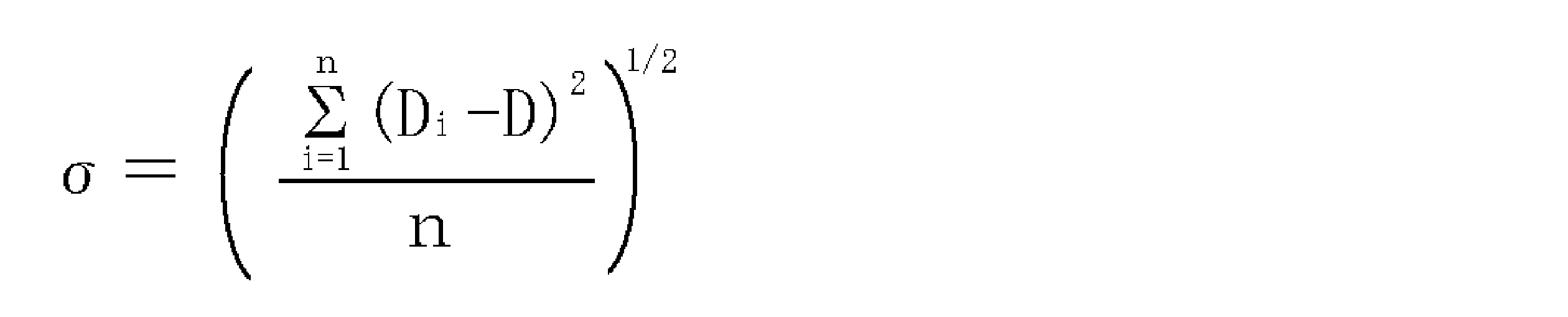 (式2中、σは結合相の厚さの標準偏差、Diは結合相の厚さの測定値、Dは結合相の厚さの平均値、nは測定数である。)。結合相の厚さの標準偏差は0.5μmを超えて大きくなると相対的に結合相が多くなる部位に加工時の応力が集中し破壊の起点になり耐欠損性が低下する。また、相対的に結合相が少なくなる部位においてcBN焼結体と被覆層との密着性が悪くなり被覆層の剥離を伴う異常摩耗が発生し耐摩耗性が低下するので、0.5μm以下とした。さらに好ましい結合相の厚さの標準偏差は0.4μm以下である。なお、結合相の厚さの標準偏差を0.05μm未満にすることは製造上難しいので、現実的には、結合相の厚さの標準偏差は0.05~0.5μmの範囲が好ましく、0.05~0.4μmの範囲がさらに好ましい。結合相の厚さの平均値と標準偏差は、cBN焼結体の断面組織をSEMで1000~5000倍に拡大して写真撮影し、得られた1000~5000倍の断面組織写真に任意に直線を引き、その直線上にある結合相について、結合相と交差する直線の長さを結合相の厚さとして測定して、その平均値と標準偏差を計算する。このとき、画像解析により、この方法に従って、結合相の厚さを測定しても好ましい。また、結合相の厚さの測定数は多いほど平均値と標準偏差の信頼性が増すので好ましく、具体的には、例えば、1断面あたり200以上の測定数で少なくとも3断面を測定した600以上の測定数であると好ましい。
(式2)
本発明のcBN焼結体の製造方法において、本発明で規定される結合相の厚さの平均値と標準偏差を実現するために、原料粉末を混合する工程ではWC基超硬合金ボールを使用した湿式ボールミル混合を行うと好ましい。しかしながら、WC基超硬合金ボールを使用するとタングステン元素がcBN焼結体に混入する。cBN焼結体に混入したタングステン元素はWC、WB、W2B、CoWB、W2Co21B6、Co3W3C、Wなどの形で存在する。これらのWの金属およびタングステン化合物は切削時の欠損や亀裂の起点となりやすいので、本発明のcBN焼結体全体に含まれるタングステン元素量は3質量%以下が好ましく、その中でも2質量%以下がさらに好ましい。しかしながら、本発明のcBN焼結体の製造工程において、結合相形成用粉末を熱処理して得られた脆性のある相を粉砕工程ではWC基超硬合金ボールを使用した湿式ボールミル混合を使用すると粉砕効率が高い。その際、cBN焼結体にタングステン元素が0.2質量%以上混入する。そのため、実際にはcBN焼結体全体に含まれるタングステン元素量は0.2~3質量%が好ましく、その中でも0.2~2質量%がさらに好ましい。なお、本発明のcBN焼結体全体に含まれるタングステン元素量はEDS(エネルギー分散型X線分析装置)またはICP-AES(誘導結合プラズマ発光分光分析装置)などを用いて測定することができる。
本発明のcBN焼結体の不可避的不純物としては、cBN焼結体の製造工程から混入されるFeを挙げることができる。不可避的不純物の合計はcBN焼結体全体に対して1.0質量%以下であり、通常はcBN焼結体全体に対して0.5質量%以下に抑えることができるので、本発明の特性値に影響を及ぼすことはない。なお、本発明においては、本発明のcBN焼結体の特性を損わない範囲で、cBNと結合相と不可避的不純物に他に、不可避的不純物とはいえない他の成分を少量含有してもよい。
本発明のcBN焼結体の熱伝導率が70W/(m・K)未満になると反応摩耗が促進され耐摩耗性が低下する。また、被覆層の高温強度が低下し被覆層の熱分解により異常摩耗が発生し耐摩耗性が低下する傾向を示すので、cBN焼結体の熱伝導率は70W/(m・K)以上が好ましく、80W/(m・K)以上であるとさらに好ましい。なお、cBN焼結体の熱伝導率は高いほど好ましいが、本発明のcBN焼結体の熱伝導率が160W/(m・K)を超えて高くなることはないので、熱伝導率は70~160W/(m・K)の範囲が好ましく、その中でも、80~160W/(m・K)の範囲がさらに好ましい。本発明のcBN焼結体の熱伝導率はレーザーフラッシュ法などにより測定することができる。
本発明の被覆層は、基材側の最下層と下部層と中間層と表面側の上部層とからなる。なお、本発明の被覆層は、最下層、下部層、中間層および上部層以外にも、上部層の表面に被覆された最外層を含むことができる。
本発明の上部層は、平均層厚0.3~2.0μmの組成式Ti(CxN(1-x))(但し、XはCとNの合計に対するCの原子比を示し、0≦x≦0.7を満足する。)で表される化合物で構成されると、高温での強度が高くなるので耐摩耗性と耐熱性を向上させることができる。また上部層の層厚が0.5μm未満であると上部層が薄すぎて耐摩耗性と耐熱性を向上させる効果が得られない。逆に上部層の層厚が2.0μmを超えて厚くなると加工初期におけるチッピングを引き起こしやすくなる。そのため上部層の平均層厚を0.5~2.0μmとした。その中でも上部層の平均層厚は0.5~1.5μmであるとさらに好ましい。ここで、上層部の平均層厚は、SEM観察により上部層の断面を5000~30000倍に拡大して、測定した。なお、本発明において、特に断らない限り、各層の平均層厚とは、SEM又はTEM(透過型電子顕微鏡)により各層の断面を観察し、5箇所以上の層厚を測定して得られた層厚の平均値を意味する。上部層のCとNの合計に対するCの原子比が0.7を超えると、上部層の粒径が微細化し粒子脱落による摩耗が進行し耐摩耗性が低下する。そのため上部層のCとNの合計に対するCの原子比を0≦x≦0.7とした。その中でも上部層のCとNの合計に対するCの原子比は0.4≦x≦0.6であるとさらに好ましい。また、上部層のCとNの合計に対するCの原子比が基材側から最表面側に向かって増加する傾斜組成層で構成されると、上部層内での応力集中が発生せず被覆層の破壊が発生しにくくなるため好ましい。
本発明の中間層は、平均層厚10~100nmのTi、Al、CrおよびSiの中から選択される少なくとも1種の成分からなる金属層であり、下部層と上部層との密着性を向上させ、下部層と上部層の剥離を防止する。中間層の平均層厚は、10nm未満であると、下部層と上部層との密着性を向上させる効果が得られず、また、被覆層の圧縮応力を緩和する効果が得られず、100nmを超えて厚くなると加工時に中間層中で滑りが発生し上部層が剥離して耐摩耗性が低下することから、中間層の平均層厚は10~100nmとした。その中でも、中間層の平均層厚は20~70nmであると好ましい。ここで、中間層の平均層厚は、SEM観察において、下部層の断面を30000~100000倍に拡大して測定した。なお、SEM観察以外にもTEM観察を行って平均層厚を測定してもよい。中間層の成分はTi、AlCrおよびTiSiの中の少なくとも1種であると上部層、下部層との化学的親和性が高く、上部層と下部層との密着性を向上させる効果が高いため好ましい。その中でも、TiおよびAlCrの少なくとも1種であるとさらに好ましい。より好ましくは、Tiである。
本発明の下部層は、硬さが高くヤング率が低いTiSiNの第1薄層と、硬さが低くヤング率が高いAlCrNの第2薄層との交互積層からなり、優れた切削性能を示す。第1薄層は、平均層厚30~200nmの組成式(Ti(1-y)Siy)N(但し、yはTiとSiの合計に対するSiの原子比を示し、0.01≦y≦0.3を満足する。)で表される化合物からなる。第1薄層は硬さが高くヤング率が低い。yが0.01未満では十分な硬さが得られず、yが0.3を超えると第1薄層中に偏析したアモルファスのSi3N4が増加し硬さが低下するので、0.01≦y≦0.3とした。その中でも、0.05≦y≦0.2であると第1薄層の硬さが高くなるのでさらに好ましい。
本発明の第2薄層は、平均層厚30~200nmの組成式(Al(1-z)Crz)N(但し、zはAlとCrの合計に対するCrの原子比を示し、0.2≦z≦0.5を満足する。)で表される化合物からなる。第2薄層は硬さが低くヤング率が高い。zが0.2未満になるとAlNの特性に近づくため硬さが低下し、zが0.5を超えて多くなると硬さが低下するので、0.2≦z≦0.5とした。その中でも、0.25≦z≦0.35であるとさらに好ましい。
本発明の下部層における第1薄層と第2薄層の平均層厚は、30nm未満であると被覆時における核発生頻度が増加して第1薄層と第2薄層の粒径が微細になり過ぎて切削時に薄層の粒子の脱落による摩耗が進行しやすくなり、200nmを超えて厚くなるとクラックの伝播を妨げる効果が減少し、耐欠損性が低下することから、本発明の下部層における第1薄層の平均層厚と第2薄層の平均層厚をそれぞれ30~200nmとした。その中でも、下部層における第1薄層の平均層厚と第2薄層の平均層厚はそれぞれ70~150nmであるとさらに好ましい。ここで、下層部の第1薄層の平均層厚および第2薄層の平均層厚は、SEM観察において、下部層の断面を30000~100000倍に拡大して測定した。なお、SEM観察以外にもTEM観察を行って平均層厚を測定してもよい。
交互積層である本発明の下部層全体の平均層厚は、0.12μm未満であると加工衝撃によるクラックの伝播を妨げる効果が減少し、1.6μmを超えて厚くなるとチッピングを引き起こしやすくなることから、0.12~1.6μmとした。その中でも、本発明の下部層全体の平均層厚は、0.3~0.8μmであるとさらに好ましい。
本発明のcBN焼結体基材と下部層の間に、組成式(Al(1-a)Cra)N(但し、aはAlとCrの合計に対するCrの原子比を示し、0.2≦a≦0.5を満足する。)で表される化合物で構成した最下層があると、cBN焼結体との化学的親和性が高いため密着性が向上する。最下層の平均層厚は、20nm未満であると十分な密着性が得られず、200nmを超えて厚くなると加工衝撃によるクラックの伝播を妨げる効果が減少し、耐欠損性や耐チッピング性が低下することから、最下層の平均層厚を20~200nmとした。その中でも、最下層の平均層厚は70~150nmであるとさらに好ましい。最下層のAlとCrの合計に対するCrの原子比が0.2未満であると最下層の結晶型が六方晶になりcBN焼結体からのエピタキシャル成長を妨げるため密着性が低下し、0.5を超えて多くなるとcBN焼結体の結合相との化学的親和性が高いAl量が減少するため基材との密着性が低下することから、0.2≦a≦0.5とした。その中でも、0.25≦a≦0.35であるとさらに好ましい。なお、(Al(1-a)Cra)Nの最下層に接する下部層は、(Ti(1-y)Siy)Nの第1薄層、(Al(1-z)Crz)Nの第2薄層のいずれでもよい。下部層の第2薄層が最下層の表面に被覆されたときは、見かけ上、平均層厚50~400nmのAlCrN層が被覆されることになる。
本発明の最外層に平均層厚0.05~3.0μmの組成式TiNで表される化合物で構成した層があると加工時に使用コーナーが識別しやすくなるので好ましい。最外層の平均層厚が0.05μm未満であると外観色が均一にならないため識別がし難く、最外層の平均層厚が3.0μmを超えて厚くなると加工中に被覆層がチッピングする傾向が高くなることから、最外層の平均層厚を0.05~3.0μmであると好ましく、その中でも、平均層厚0.1~1.0μmであるとさらに好ましい。また、本発明の被覆層全体の総層厚は、平均層厚で0.4μm未満になると耐摩耗性が低下する傾向を示し、6.8μmを超えて厚くなると耐欠損性が低下する傾向を示すことから、本発明の被覆層全体の総層厚は、平均層厚で0.4~6.8μmであると好ましい。
本発明の被覆cBN焼結体工具は、少なくとも刃先が本発明の被覆cBN焼結体からなる。刃先以外は、本発明の被覆cBN焼結体でもよく、本発明の被覆cBN焼結体と異なる材料、例えば超硬合金、でもよい。具体的には、切削工具形状に加工した超硬合金の刃先部分に本発明のcBN焼結体をろう付けし、その後、本発明のcBN焼結体の表面に本発明の被覆層を被覆してもよい。
本発明の被覆cBN焼結体工具は、基材のcBN焼結体が優れた耐欠損性と高い熱伝導率を有する。cBN焼結体と被覆層との密着性を向上させることで、被覆層の剥離などの異常摩耗を抑制する。また、cBN焼結体の熱伝導率が高いことから加工時の発熱による温度上昇が抑えられ、温度上昇による被覆層の強度低下を防いでいる。このような理由により、本発明の被覆cBN焼結体工具は、優れた耐摩耗性および優れた耐欠損性を示す。
本発明の被覆cBN焼結体工具は、耐摩耗性、耐欠損性および基材と被覆層との密着性に優れる。本発明の被覆cBN焼結体工具は、切削工具として優れた性能を示し、工具寿命を延長することができる。その中でも、焼入れ鋼やプリハードン鋼などの高硬度材の切削用として本発明の被覆cBN焼結体工具を用いると工具寿命を延長する効果が高く、その中でも、HRC40以上の硬度を有する高硬度材の切削用として用いるとさらに好ましい。
本発明の被覆cBN焼結体は、例えば、以下の方法で製造することができる。
[工程1]平均粒径2.0μm超7.0μm以下の粗粒cBN粉末と、平均粒径0.5μm以上2.0μm以下の微粒cBN粉末と、Ti、W、Co、Alの金属、これら金属の炭化物、窒化物、硼化物、酸化物およびこれらの相互固溶体の中から選ばれた少なくとも1種からなる結合相形成用粉末を用意し、粗粒cBN粉末と微粒cBN粉末の割合は体積比で粗粒cBN粉末:微粒cBN粉末=(9.5~8):(0.5~2)(但し、粗粒cBN粉末と微粒cBN粉末の合計は10とする。)の範囲内で、粗粒cBN粉末と微粒cBN粉末の合計は75~85体積%、結合相形成用粉末は15~25体積%、これらの合計は100体積%となるように粗粒cBN粉末と微粒cBN粉末と結合相形成用粉末を秤量する。上記のように平均粒径2.0μm超7.0μm以下の粗粒cBN粉末と平均粒径0.5μm以上2.0μm以下の微粒cBN粉末を、体積比で粗粒cBN粉末:微粒cBN粉末=(9.5~8):(0.5~2)(但し、粗粒cBN粉末と微粒cBN粉末の合計は10とする。)の範囲内にすることにより、cBNの平均粒径を1.5~4.0μmの範囲内にするとともに、cBN焼結体の結合相の厚さを薄くし、cBN焼結体の熱伝導率を高くすることができる。
[工程2]cBN粉末以外の結合相形成用粉末を、WC基超硬合金ボールと有機溶媒とポットとからなる湿式ボールミルを用いて混合し、有機溶媒を蒸発させ、混合粉末を得る。
[工程3]混合粉末を700℃以上1000℃以下の温度で熱処理して反応させて脆性のある相にする。
[工程4]脆性のある相をWC基超硬合金ボールと有機溶媒とポットとからなる湿式ボールミルを用いて混合し、細かく粉砕する。
[工程5]工程4で得られた脆性のある相の粉末と平均粒径0.5μm以上2.0μm以下の微粒cBN粉末とを混合し、細かく粉砕した脆性のある相と微粒cBN粉末とをほぐして、これらを均一に分散させる。混合し均一に分散する方法としては、混合時間1~24時間の湿式ボールミル、混合時間1~30分間の超音波混合などを挙げることができる。
[工程6]工程5で得られた混合粉末に、平均粒径2.0μm超7.0μm以下の粗粒cBN粉末を加えて混合し、これらを均一に分散させる。混合し均一に分散する方法としては、混合時間2~6時間の湿式ボールミル、混合時間1~30分間の超音波混合などを挙げることができる。
[工程7]工程6で得られた混合粉末をTa、Nb、Mo、Zrなどの金属カプセルに入れ、金属カプセルを超高圧高温発生装置に装填し、圧力6~8GPa、温度1200~1600℃の条件下で焼結すると本発明のcBN焼結体が得られる。
[工程8]得られた本発明のcBN焼結体は所定の工具形状に加工する。このとき、本発明のcBN焼結体全体を工具形状に加工してもよく、あるいは、工具形状に加工した他の材料(例えば、超硬合金)の刃先に本発明のcBN焼結体をろう付けしてもよい。
本発明の被覆層をcBN焼結体の表面に被覆する方法としては、アークイオンプレーティング法やマグネトロンスッパタリング法などが挙げられるが、アークイオンプレーティング法は金属元素のイオン化率が高いことや被覆層を被覆する前にcBN焼結体の表面に対してエッチング処理が可能であり、被覆層とcBN焼結体との密着性に優れるので、さらに好ましい。以下にアークイオンプレーティング法による被覆方法を示す。なお、各層の層厚はアーク放電時間で調節できるが、金属ターゲットの種類にも影響を受けるので、金属ターゲットの種類に合わせてアーク放電時間を適宜調整するとよい。
[工程9]工程8により得られた本発明のcBN焼結体工具の表面を有機溶剤や水などで洗浄し、これを基材とする。被覆層の金属元素に対応した金属ターゲットを配したアークイオンプレーティング装置内に、基材を装着して、装置内を排気し、ヒーターで室温から400~650℃の範囲にある所定の温度まで加熱しながら、装置内の圧力が1.0×10⁻⁵~1.0×10⁻³Paになるまで真空引きを行う。
[工程10]次にアルゴンガスを導入して装置内の圧力を0.5~3.0Paに調整し、-100~-1000Vの基材直流バイアス電圧を基材に印加して、基材表面をアルゴンイオンによってエッチング処理する。エッチング処理した後、装置内からアルゴンガスを排気する。
[工程11]装置内に窒素ガスを導入して装置内の圧力を2.0~4.0Paに調整し、基材直流バイアス電圧を-30~-50Vに調整し、最下層の金属元素に対応した金属ターゲットを配したカソード電極に100~180Aのアーク電流を供給して最下層を被覆する。最下層を被覆した後、アーク放電を停止する。
[工程12]装置内に窒素ガスを導入して装置内の圧力を2.0~4.0Paに調整し、基材直流バイアス電圧を-20~-50Vに調整し、下部層の第1薄層の金属元素に対応した金属ターゲットを配したカソード電極に100~180Aのアーク電流を供給して下部層の第1薄層を被覆した。第1薄層を被覆した後、アーク放電を停止し、下部層の第2薄層の金属元素に対応した金属ターゲットを配したカソード電極に100~180Aのアーク電流を供給して下部層の第2薄層を被覆する。第2薄層を被覆した後、アーク放電を停止する。このプロセスを繰り返すことにより、第1薄層と第2薄層とを交互に積層した交互積層の下層部を被覆する。下層部を被覆した後、アーク放電を停止して反応ガスである窒素ガスを排気する。なお、下部層は最下層側に第2薄膜を被覆した後に第1薄層を被覆し、それらを交互に被覆してもよい。
[工程13]装置内にアルゴンガスを導入して装置内の圧力を2.0~4.0Paに調整し、基材直流バイアス電圧を-20~-50Vに調整し、中間層の金属元素に対応した金属ターゲットを配したカソード電極に80~120Aのアーク電流を供給して中間層を被覆する。中間層を被覆した後、アーク放電を停止してアルゴンガスを排気する。
[工程14]装置内に窒素ガスとアセチレンガスを導入して装置内の圧力2.0~4.0Paに調整し、基材直流バイアス電圧を-30~-120Vに調整し、Tiターゲットを配したカソード電極に100~180Aのアーク電流を供給して上部層を被覆する。このとき、上部層のコーティング初期に窒素ガスの流量比を多くし、コーティング中に徐々にアセチレンガスの流量比を増加させても好ましい。上部層を被覆した後、アーク放電を停止して窒素ガスとアセチレンガスを排気する。
上述の工程で本発明の被覆cBN焼結体工具を製造することができる。さらに最外層を被覆する場合は、引き続き、以下の工程を行うとよい。
[工程15]上部層を被覆した後、装置内に窒素ガスを導入して装置内の圧力を2.0~4.0Paに調整し、基材直流バイアス電圧を-20~-50Vに調整し、最外層の金属元素に対応した金属ターゲットを配したカソード電極に100~180Aのアーク電流を供給して最外層を被覆する。最外層を被覆した後、アーク放電を停止し反応ガスである窒素ガスを排気する。
[工程15]上部層を被覆した後、装置内に窒素ガスを導入して装置内の圧力を2.0~4.0Paに調整し、基材直流バイアス電圧を-20~-50Vに調整し、最外層の金属元素に対応した金属ターゲットを配したカソード電極に100~180Aのアーク電流を供給して最外層を被覆する。最外層を被覆した後、アーク放電を停止し反応ガスである窒素ガスを排気する。
[実施例1]
(基材の作製)
原料粉末として、レーザー回折法で測定して得られた平均粒径がそれぞれ、平均粒径5.5μmの粗粒cBN粉末、平均粒径3.2μmの粗粒cBN粉末、平均粒径0.3μmの微粒cBN粉末、平均粒径1.0μmの微粒cBN粉末、平均粒径1.5μmのTiN粉末、平均粒径3.1μmのAl粉末を用意し、表1に示す配合組成になるように秤量した。
(基材の作製)
原料粉末として、レーザー回折法で測定して得られた平均粒径がそれぞれ、平均粒径5.5μmの粗粒cBN粉末、平均粒径3.2μmの粗粒cBN粉末、平均粒径0.3μmの微粒cBN粉末、平均粒径1.0μmの微粒cBN粉末、平均粒径1.5μmのTiN粉末、平均粒径3.1μmのAl粉末を用意し、表1に示す配合組成になるように秤量した。

cBN粉末以外の結合相形成用粉末をWC基超硬合金ボールと有機溶媒とポットとからなる湿式ボールミルを用いて混合した。得られた混合粉末を850℃の温度で熱処理して反応させ脆性のある相にした。得られた脆性のある相をWC基超硬合金ボールと有機溶媒とポットとからなる湿式ボールミルを用いて細かく粉砕した。
基材番号1~3、5、6については、細かく粉砕した脆性のある相の粉末に平均粒径1.0μmの微粒cBN粉末を加えて、WC基超硬合金ボールと有機溶媒とポットとからなる湿式ボールミルを用いて表2に示す混合方法で混合した。得られた混合物にさらに平均粒径3.2~5.5μmの粗粒cBN粉末を加えて、WC基超硬合金ボールと有機溶媒とポットとからなる湿式ボールミルを用いて表2に示す混合方法で混合して混合粉末を得た。
基材番号4については、細かく粉砕した脆性のある相の粉末に平均粒径1.0μmの微粒cBN粉末を加えて、表2に示す超音波混合を行った。得られた混合物にさらに平均粒径3.2μmの粗粒cBN粉末を加えて、表2に示す超音波混合を行って混合粉末を得た。

基材番号7については、細かく粉砕した脆性のある相の粉末に平均粒径0.3μmの微粒cBN粉末を加えて、WC基超硬合金ボールと有機溶媒とポットとからなる湿式ボールミルを用いて10時間混合して混合粉末を得た。
基材番号8については、細かく粉砕した脆性のある相の粉末に平均粒径5.5μmの粗粒cBN粉末を加えて、WC基超硬合金ボールと有機溶媒とポットとからなる湿式ボールミルを用いて2時間混合して混合粉末を得た。
上記のようにして得られた基材番号1~8の混合粉末をTaカプセルに入れ、混合粉末の入ったTaカプセルを超高圧高温発生装置に装填し、表3に示す焼結温度と焼結圧力で焼結して基材番号1~8のcBN焼結体を得た。

得られたcBN焼結体についてX線回折測定を行って、cBN焼結体の組成を定性分析した。次にcBN焼結体の断面組織をSEMで3000~5000倍に拡大して撮影した。得られた断面組織写真を画像解析することでcBNと結合相の含有量(体積%)を求めた。また、断面組織写真に任意に直線を引き、その直線上にある結合相について、結合相と交差する直線の長さを結合相の厚さとして測定して、その平均値と標準偏差を求めた。このとき結合相の厚さの測定数は1試料当たり600箇所であった。さらに断面組織をSEMで1000~5000倍に拡大して撮影した写真からフルマンの式を用いることでcBNの平均粒径を求めた。これらの結果は表4に示した。
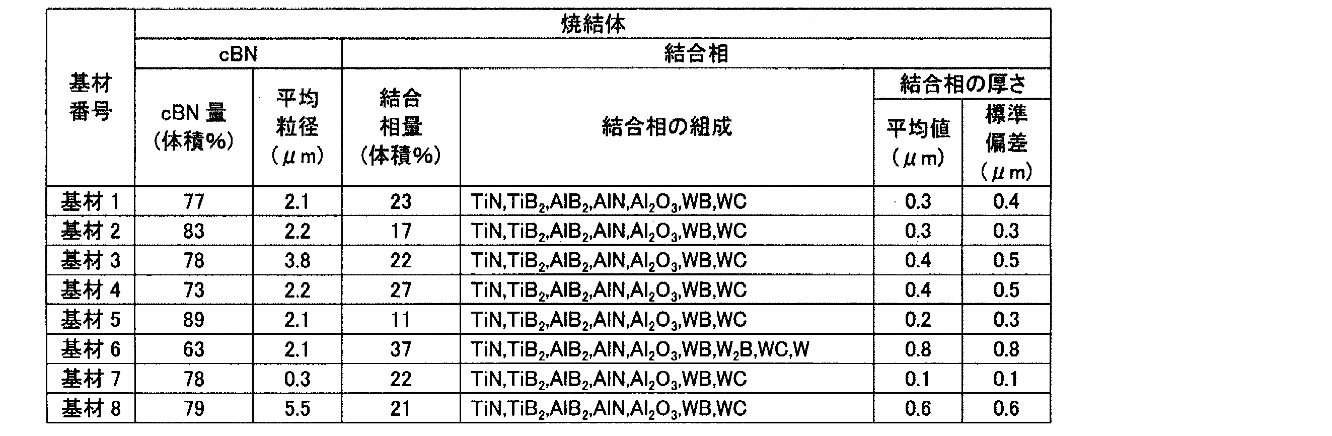
EDSを用いてcBN焼結体に含まれるタングステン元素量を測定した。また、cBN焼結体の熱伝導率をレーザーフラッシュ法により測定した。それらの結果は表5に示した。
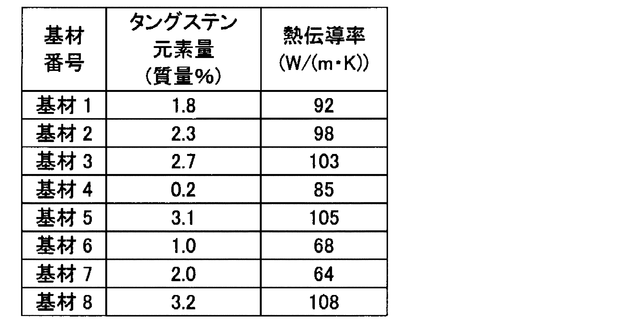
発明品1~8と比較品1~8の被覆cBN焼結体工具は、表6に示した基材に、表6に示す組成及び層厚を有する最下層、下部層、中間層、上部層、最外層(発明品6、7および比較品6、7は除く)を、以下の条件で順次形成した。
(1)基材の準備
発明品1~8と比較品1~8のそれぞれの試料について、ISO規格CNGA120408形状の超硬合金を台金とし、この超硬合金台金の刃先となるコーナー部に、表6に示したcBN焼結体をろう付けした。これらを上下面、外周面を#270メッシュのダイヤモンド砥石で研削加工し、続いて切刃稜線に#400メッシュのダイヤモンド砥石により角度-25°×幅0.15mmのチャンファホーニングを施した。さらに逃げ面とチャンファホーニング面との稜線に回転ブラシを押し当てて丸ホーニング加工を行った。加工時間を調整しながらコントレーサーで測定し、所望の曲率半径の丸ホーニングを施した。加工後に得られたcBN焼結体工具を基材とした。エタノールおよびアセトンで基材を洗浄し、その後に真空乾燥処理を行った。
発明品1~8と比較品1~8のそれぞれの試料について、ISO規格CNGA120408形状の超硬合金を台金とし、この超硬合金台金の刃先となるコーナー部に、表6に示したcBN焼結体をろう付けした。これらを上下面、外周面を#270メッシュのダイヤモンド砥石で研削加工し、続いて切刃稜線に#400メッシュのダイヤモンド砥石により角度-25°×幅0.15mmのチャンファホーニングを施した。さらに逃げ面とチャンファホーニング面との稜線に回転ブラシを押し当てて丸ホーニング加工を行った。加工時間を調整しながらコントレーサーで測定し、所望の曲率半径の丸ホーニングを施した。加工後に得られたcBN焼結体工具を基材とした。エタノールおよびアセトンで基材を洗浄し、その後に真空乾燥処理を行った。
それぞれの試料について、基材をアークイオンプレーティング装置内の回転テーブル上に装着し、カソード電極(蒸発源)としてそれぞれ表6に示される被覆層の金属元素に対応した金属ターゲットを配した。まず、装置内を排気し、ヒーターで500℃に加熱しながら、装置内の圧力が1.0×10⁻⁴Paになるまで真空引きを行った。次にアルゴンガスを導入し装置内の圧力を0.7Paに保持し、テーブルを回転した状態で-200Vの基材直流バイアス電圧を基材に印加し、基材表面をアルゴンイオンによってエッチングし、その後、装置内からアルゴンガスを排気した。
(2)最下層の形成
それぞれの試料について、テーブルを回転した状態で、反応ガスとして窒素ガスを装置内に導入し、窒素ガスの流量を調整して装置内の圧力を3.0Paに調整し、基材直流バイアス電圧を-40Vに調整し、表6に示される最下層の金属元素に対応した金属ターゲットを配したカソード電極に150Aのアーク電流を供給し、形成する層厚に依存して放電時間を5~15分の範囲で変化させて最下層を被覆した後、アーク放電を停止した。
それぞれの試料について、テーブルを回転した状態で、反応ガスとして窒素ガスを装置内に導入し、窒素ガスの流量を調整して装置内の圧力を3.0Paに調整し、基材直流バイアス電圧を-40Vに調整し、表6に示される最下層の金属元素に対応した金属ターゲットを配したカソード電極に150Aのアーク電流を供給し、形成する層厚に依存して放電時間を5~15分の範囲で変化させて最下層を被覆した後、アーク放電を停止した。
(3)下部層の形成
続いて、それぞれの試料について、テーブルを回転した状態で、反応ガスとして窒素ガスを装置内に導入し、窒素ガスの流量を調整して装置内の圧力を3.0Paに調整し、基材直流バイアス電圧を-40Vに保持したまま、表6に示される下部層の第1薄層の金属元素に対応した金属ターゲットを配したカソード電極に150Aのアーク電流を供給し、形成する層厚に依存して放電時間を5~20分の範囲で変化させて下部層の第1薄層を被覆した。第1薄層を被覆した後、アーク放電を停止し、表6に示される下部層の第2薄層の金属元素に対応した金属ターゲットを配したカソード電極に150Aのアーク電流を供給し、形成する層厚に依存して放電時間を8~25分の範囲で変化させて下部層の第2薄層を被覆した。第2薄層を被覆した後、アーク放電を停止した。このプロセスを繰り返すことにより、発明品1~8と比較品1~4については、第1薄層が基材側に第2薄層が表面側になるように第1薄層から、表6に示す平均層厚の第1薄層を2~4層、表6に示す平均層厚の第2薄層を2~4層、合計で4~8層になるように第1薄層と第2薄層とを交互に積層した交互積層の下層部を被覆した後、比較品5~8については、第1薄層が基材側に第2薄層が表面側になるように第1薄層から、表6に示す平均層厚の第1薄層を1~20層、表6に示す平均層厚の第2薄層を1~20層、合計で2~40層になるように第1薄層と第2薄層とを交互に積層した交互積層の下層部を被覆した後、アーク放電を停止して反応ガスである窒素ガスを排気した。
続いて、それぞれの試料について、テーブルを回転した状態で、反応ガスとして窒素ガスを装置内に導入し、窒素ガスの流量を調整して装置内の圧力を3.0Paに調整し、基材直流バイアス電圧を-40Vに保持したまま、表6に示される下部層の第1薄層の金属元素に対応した金属ターゲットを配したカソード電極に150Aのアーク電流を供給し、形成する層厚に依存して放電時間を5~20分の範囲で変化させて下部層の第1薄層を被覆した。第1薄層を被覆した後、アーク放電を停止し、表6に示される下部層の第2薄層の金属元素に対応した金属ターゲットを配したカソード電極に150Aのアーク電流を供給し、形成する層厚に依存して放電時間を8~25分の範囲で変化させて下部層の第2薄層を被覆した。第2薄層を被覆した後、アーク放電を停止した。このプロセスを繰り返すことにより、発明品1~8と比較品1~4については、第1薄層が基材側に第2薄層が表面側になるように第1薄層から、表6に示す平均層厚の第1薄層を2~4層、表6に示す平均層厚の第2薄層を2~4層、合計で4~8層になるように第1薄層と第2薄層とを交互に積層した交互積層の下層部を被覆した後、比較品5~8については、第1薄層が基材側に第2薄層が表面側になるように第1薄層から、表6に示す平均層厚の第1薄層を1~20層、表6に示す平均層厚の第2薄層を1~20層、合計で2~40層になるように第1薄層と第2薄層とを交互に積層した交互積層の下層部を被覆した後、アーク放電を停止して反応ガスである窒素ガスを排気した。
(4)中間層の形成
交互積層の下部層を被覆した後、それぞれの試料について、アルゴンガスを導入し、装置内の圧力を3.0Paに保持し、-40Vの基材直流バイアス電圧を基材に印加した状態で、表6に示される中間層の金属元素に対応した金属ターゲットを配したカソード電極に100Aのアーク電流を供給し、形成する層厚に依存して発明品1~8と比較品1~4については、放電時間を4~15分の範囲で変化させて、比較品5~8については、放電時間を8~15分の範囲で変化させて、それぞれ、中間層を被覆した後、アーク放電を停止しアルゴンガスを排気した。
交互積層の下部層を被覆した後、それぞれの試料について、アルゴンガスを導入し、装置内の圧力を3.0Paに保持し、-40Vの基材直流バイアス電圧を基材に印加した状態で、表6に示される中間層の金属元素に対応した金属ターゲットを配したカソード電極に100Aのアーク電流を供給し、形成する層厚に依存して発明品1~8と比較品1~4については、放電時間を4~15分の範囲で変化させて、比較品5~8については、放電時間を8~15分の範囲で変化させて、それぞれ、中間層を被覆した後、アーク放電を停止しアルゴンガスを排気した。
(5-1)上部層の形成
それぞれの試料発明品1~5と比較品1~4、5、8について、中間層を被覆した後、反応ガスとして窒素ガスを装置内に導入し、窒素ガスの流量を調整して装置内の圧力を3.0Paに調整し、基材直流バイアス電圧を-100Vに調整し、Tiターゲットを配したカソード電極に150Aのアーク電流を供給した。続いて、すぐにアセチレンガスを導入した。その後、アセチレンガスの流量を徐々に増加させ、目標の層厚が形成される最終段階で窒素ガス:アセチレンガスの流量比(体積比)が(5~3):1の割合の混合ガスになるように調整し、さらに混合ガスの流量を調整して装置内の圧力が3.0Paになるように調整した。なお、発明品1~5と比較品1~4については、放電時間は形成する層厚に依存して15~90分の範囲で調整した。比較品5、8については、放電時間50分で上部層を被覆した。このようにして上部層を被覆した後、アーク放電を停止し窒素ガスおよびアセチレンガスを排気した。
(5-2)上部層の形成
発明品6~8については、中間層を被覆した後、反応ガスとして窒素ガスとアセチレンガスを装置内に導入した。このとき窒素ガス:アセチレンガスの流量比(体積比)が(8~5):1の割合の混合ガスになるように調整し、さらに混合ガスの流量を調整して装置内の圧力を3.0Paに調整し、基材直流バイアス電圧を-100Vに調整し、Tiターゲットを配したカソード電極に150Aのアーク電流を供給し、形成する層厚に依存して放電時間を20~50分の範囲で変化させて上部層を被覆した後、アーク放電を停止し窒素ガスとアセチレンガスを排気した。
(5-3)上部層の形成
比較品6、7については、反応ガスとして窒素ガスを装置内に導入し、窒素ガスの流量を調整して装置内の圧力を3.0Paに調整し、基材直流バイアス電圧を-40Vに調整し、表6に示される上部層の金属元素に対応した金属ターゲットを配したカソード電極に150Aのアーク電流を供給し、形成する層厚に依存して放電時間を50~60分の範囲で変化させて上部層を被覆した後、アーク放電を停止し反応ガスである窒素ガスを排気した。このようにして比較品6、7の被覆cBN焼結体工具を作製した。
(6)最外層の形成
続いて、発明品1~5、8と比較品1~4については、反応ガスとして窒素ガスを装置内に導入し、窒素ガスの流量を調整して装置内の圧力を3.0Paに調整し、基材直流バイアス電圧を-40Vに調整し、表6に示される最外層の金属元素に対応した金属ターゲットを配したカソード電極に150Aのアーク電流を供給し、形成する層厚に依存して放電時間を15~45分の範囲で変化させて上部層を被覆した後、アーク放電を停止し反応ガスである窒素ガスを排気した。
また、比較品5、8については、反応ガスとして窒素ガスを装置内に導入し、窒素ガスの流量を調整して装置内の圧力を3.0Paに調整し、基材直流バイアス電圧を-40Vに調整し、Tiターゲットを配したカソード電極に150Aのアーク電流を供給し、形成する層厚に依存して放電時間を15分で上部層を被覆した後、アーク放電を停止し、窒素ガスを排気した。このようにして比較品5、8の被覆cBN焼結体工具を作製した。
このようにして発明品1~8と比較品1~8の被覆cBN焼結体工具をそれぞれ作製した。
得られた発明品および比較品について、SEM観察、SEM付属のEDS測定、TEM観察、TEM付属のEDS測定を行って、各層の層厚と組成を測定した。それらの結果を表6に示した。さらに、得られた発明品および比較品について下記の切削試験[1]、[2]、[3]を行った。
得られた発明品および比較品について、SEM観察、SEM付属のEDS測定、TEM観察、TEM付属のEDS測定を行って、各層の層厚と組成を測定した。それらの結果を表6に示した。さらに、得られた発明品および比較品について下記の切削試験[1]、[2]、[3]を行った。

切削試験[1]:連続切削
加工形態:外径連続旋削加工、DRY
被削材:SCM415H(浸炭焼入れ鋼)、HRC58~62、円柱状(外径63mm、長さ200mm)
切削速度:150m/min
送り:0.10mm/rev
切込み:0.15mm
工具寿命:逃げ面摩耗量が0.15mmになるまでの加工時間もしくは刃先欠損が発生するまでの加工時間
加工形態:外径連続旋削加工、DRY
被削材:SCM415H(浸炭焼入れ鋼)、HRC58~62、円柱状(外径63mm、長さ200mm)
切削速度:150m/min
送り:0.10mm/rev
切込み:0.15mm
工具寿命:逃げ面摩耗量が0.15mmになるまでの加工時間もしくは刃先欠損が発生するまでの加工時間
切削試験[2]:深切込み旋削
加工形態:表面と内部で硬さの異なる浸炭焼入れ鋼の旋削加工((A)HRC62~58の硬質部分について1パス当たり加工幅10mmの旋削加工を3パス行う。→(B)HRC57~40の軟質部分について1パス当たり加工幅10mmの旋削加工を3パス行う。
以降、(A)→(B)→(A)→(B)の加工を工具寿命になるまで繰り返す。)、DRY
被削材:SCM415H(浸炭焼入れ鋼)、表面から深さ0.9mmまでの硬質部分の硬さはHRC62~58、硬質部分より内部の軟質部分の硬さはHRC57~40、円柱状(外径63mm、長さ200mm)
切削速度:100m/min
送り:0.10mm/rev
切込み:0.30mm
1パス当たり加工幅:10mm
工具寿命:逃げ面摩耗量が0.15mmになるまでの加工時間もしくは刃先欠損が発生するまでの加工時間
切削試験[3]:断続切削
加工形態:外径断続旋削加工、DRY
被削材:SCM435H(浸炭焼入れ鋼)、HRC58~60、V溝2本付き円柱状(外径48mm、長さ200mm)
切削速度:150m/min
送り:0.10mm/rev
切込み:0.15mm
工具寿命:逃げ面摩耗量が0.15mmになるまでの加工時間もしくは刃先欠損が発生するまでの加工時間
加工形態:外径断続旋削加工、DRY
被削材:SCM435H(浸炭焼入れ鋼)、HRC58~60、V溝2本付き円柱状(外径48mm、長さ200mm)
切削速度:150m/min
送り:0.10mm/rev
切込み:0.15mm
工具寿命:逃げ面摩耗量が0.15mmになるまでの加工時間もしくは刃先欠損が発生するまでの加工時間
表7には、切削試験[1]、[2]、[3]における工具寿命(分)を記載した。また、切削試験[1]、[2]、[3]の工具寿命と損傷形態から、発明品と比較品の切削性能について総合評価を行った。切削試験[1]、[2]、[3]における工具寿命について、切削試験[1]では、100分以上を1点、90~99分を2点、80~89分を3点、70~79分を4点、69分以下を5点とした点数付けを行った。切削試験[2]では、20分以上を1点、17~19分を2点、14~16分を3点、11~13分を4点、10分以下を5点とした点数付けを行った。切削試験[3]では、40分以上を1点、33~39分を2点、26~32分を3点、19~25分を4点、18分以下を5点とした点数付けを行った。次に、切削試験[1]、[2]、[3]における点数を合計し、3~5点を◎、6~8点を○、9~12点を▲、13~15点を×とした総合評価(良い◎>○>▲>×悪い)を行った。総合評価の結果は表7に併記した。

表7から、発明品は比較品と比較して、いずれの加工条件においても工具寿命が長く、総合評価が良好であることが分かる。
本発明の被覆cBN焼結体工具は、優れた耐欠損性と優れた耐摩耗性を有する。切削工具として用いると優れた性能を発揮し、工具寿命を延長できる。特に高硬度材の切削加工において、その効果が高い。
Claims (23)
- cBN焼結体の基材とその表面に被覆された被覆層とからなり、
cBN焼結体は、cBN:73~84体積%と、Ti、W、Co、Alの金属、これら金属の炭化物、炭窒化物、窒化物、硼窒化物、硼化物、酸化物およびこれらの相互固溶体の中から選ばれた少なくとも1種からなる結合相および不可避的不純物:16~27体積%とからなり、cBNの平均粒径は1.5~4.0μmであり、結合相は、結合相の厚さの平均値が0.05~0.5μmであり、結合相の厚さの標準偏差が0.5μm以下であり、
被覆層は上部層と中間層と下部層と最下層とからなり、
(1)上部層を、平均層厚0.3~2.0μmの組成式Ti(CxN(1-x))
但し、xはCとNの合計に対するCの原子比を示し、0≦x≦0.7を満足する、
で表される化合物で構成し、
(2)中間層を、平均層厚10~100nmの成分Ti、Al、CrおよびSiの中から選択される少なくとも1種の金属で構成し、
(3)下部層を、
平均層厚30~200nmの組成式(Ti(1-y)Siy)N
但し、yはTiとSiの合計に対するSiの原子比を示し、0.01≦y≦0.3を満足する、
で表される化合物からなる第1薄層と、
平均層厚30~200nmの組成式(Al(1-z)Crz)N
但し、zはAlとCrの合計に対するCrの原子比を示し、0.2≦z≦0.5を満足する、
で表される化合物からなる第2薄層とを
交互に積層した交互積層全体の平均層厚が0.12~1.6μmである交互積層で構成し、
(4)最下層を、平均層厚20~200nmの組成式(Al(1-a)Cra)N
但し、aはAlとCrの合計に対するCrの原子比を示し、0.2≦a≦0.5を満足する、
で表される化合物で構成することを特徴とする被覆cBN焼結体工具。 - cBN焼結体が、cBN:75~80体積%と、結合相および不可避的不純物:20~25体積%とからなり、cBNの平均粒径は2.0~3.0μmであり、結合相は、結合相の厚さの平均値が0.1~0.4μmであり、結合相の厚さの標準偏差が0.05~0.4μmである請求項1に記載の被覆cBN焼結体工具。
- cBN焼結体の熱伝導率が70W/(m・K)以上である請求項1または2に記載の被覆cBN焼結体工具。
- cBN焼結体の熱伝導率が80~160W/(m・K)である請求項1~3のいずれか1項に記載の被覆cBN焼結体工具。
- cBN焼結体に含まれるタングステン元素量がcBN焼結体全体に対して3質量%以下である請求項1~4のいずれか1項に記載の被覆cBN焼結体工具。
- cBN焼結体に含まれるタングステン元素量がcBN焼結体全体に対して0.2~2質量%である請求項1~5のいずれか1項に記載の被覆cBN焼結体工具。
- cBN焼結体の結合相が、Ti、W、Co、Alの金属、これら金属の炭化物、炭窒化物、窒化物、硼窒化物、硼化物、酸化物およびこれらの相互固溶体の中から選ばれた少なくとも1種からなる請求項1~6のいずれか1項に記載の被覆cBN焼結体工具。
- cBN焼結体の結合相が、TiN、TiCN、TiC、TiB2、TiBN、TiAlN、Ti2AlN、AlN、AlB2、Al2O3、WC、WB、W2B、CoWB、W2Co21B6、Co3W3C、W、CoおよびTiから選ばれた少なくとも1種からなる請求項1~7のいずれか1項に記載の被覆cBN焼結体工具。
- cBN焼結体の結合相が、TiN、TiCN、TiC、AlN、AlB2、Al2O3、TiB2、CoWB、W2Co21B6およびWCの中の少なくとも1種からなる請求項1~8のいずれか1項に記載の被覆cBN焼結体工具。
- cBN焼結体の結合相が、TiN、TiCN、TiC、AlN、AlB2、Al2O3およびTiB2の中の少なくとも1種からなる請求項1~9のいずれか1項に記載の被覆cBN焼結体工具。
- 結合相の厚さの平均値が0.1~0.4μmである請求項1~10のいずれか1項に記載の被覆cBN焼結体工具。
- 中間層を、平均層厚10~100nmの組成式TiまたはAlCrで表される金属で構成した請求項1~11のいずれか1項に記載の被覆cBN焼結体工具。
- 中間層を、平均層厚10~100nmの組成式Tiで表される金属で構成した請求項1~12のいずれか1項に記載の被覆cBN焼結体工具。
- 上部層を、平均層厚0.3~2.0μmの組成式Ti(CxN(1-x))
但し、xはCとNの合計に対するCの原子比を示し、0≦x≦0.7を満足する、
で表される化合物で構成し、CとNの合計に対するCの原子比が基材側から表面側に向かって増加する傾斜組成層で構成した請求項1~13のいずれか1項に記載の被覆cBN焼結体工具。 - 上部層が、平均層厚0.5~1.5μmの組成式Ti(CxN(1-x))
但し、xはCとNの合計に対するCの原子比を示し、0.4≦x≦0.6を満足する、
で表される化合物で構成されたものである請求項1~14のいずれか1項に記載の被覆cBN焼結体工具。 - 下部層の第1薄層が、平均層厚70~150nmの組成式(Ti(1-y)Siy)N
但し、yはTiとSiの合計に対するSiの原子比を示し、0.05≦y≦0.2を満足する、
で表される化合物で構成されたものである請求項1~15のいずれか1項に記載の被覆cBN焼結体工具。 - 下部層の第2薄層が、平均層厚70~150nmの組成式(Al(1-z)Crz)N
但し、zはAlとCrの合計に対するCrの原子比を示し、0.25≦z≦0.35を満足する、
で表される化合物で構成されたものである請求項1~16のいずれか1項に記載の被覆cBN焼結体工具。 - 下部層が、交互に積層した交互積層全体の平均層厚が0.3~0.8μmである交互積層で構成されたものである請求項1~17のいずれか1項に記載の被覆cBN焼結体工具。
- 最下層が、平均層厚70~150nmの組成式(Al(1-a)Cra)N(但し、aはAlとCrの合計に対するCrの原子比を示し、0.25≦a≦0.35を満足する。)で表される化合物で構成されたものである請求項1~18のいずれか1項に記載の被覆cBN焼結体工具。
- 被覆層全体の総層厚が平均膜厚で0.4~6.8μmである請求項1~19のいずれか1項に記載の被覆cBN焼結体工具。
- 上部層の表面に、平均層厚0.05~3.0μmの組成式TiNで表される化合物で構成された最外層を被覆した請求項1~20のいずれか1項に記載の被覆cBN焼結体工具。
- 請求項1~21のいずれか1項記載の被覆cBN焼結体工具は高硬度材の加工に用いられる高硬度材用被覆cBN焼結体工具。
- 高硬度材はHRC40以上の硬度を有する高硬度材である請求項22に記載の高硬度材用被覆cBN焼結体工具。
Priority Applications (3)
| Application Number | Priority Date | Filing Date | Title |
|---|---|---|---|
| US13/808,575 US8673435B2 (en) | 2010-07-06 | 2011-07-06 | Coated cBN sintered body tool |
| EP11803609.4A EP2591869B1 (en) | 2010-07-06 | 2011-07-06 | Coated polycrystalline cbn tool |
| JP2012523891A JP5392408B2 (ja) | 2010-07-06 | 2011-07-06 | 被覆cBN焼結体工具 |
Applications Claiming Priority (2)
| Application Number | Priority Date | Filing Date | Title |
|---|---|---|---|
| JP2010-153696 | 2010-07-06 | ||
| JP2010153696 | 2010-07-06 |
Publications (1)
| Publication Number | Publication Date |
|---|---|
| WO2012005275A1 true WO2012005275A1 (ja) | 2012-01-12 |
Family
ID=45441252
Family Applications (1)
| Application Number | Title | Priority Date | Filing Date |
|---|---|---|---|
| PCT/JP2011/065424 WO2012005275A1 (ja) | 2010-07-06 | 2011-07-06 | 被覆cBN焼結体工具 |
Country Status (4)
| Country | Link |
|---|---|
| US (1) | US8673435B2 (ja) |
| EP (1) | EP2591869B1 (ja) |
| JP (1) | JP5392408B2 (ja) |
| WO (1) | WO2012005275A1 (ja) |
Cited By (19)
| Publication number | Priority date | Publication date | Assignee | Title |
|---|---|---|---|---|
| WO2014049105A1 (de) * | 2012-09-28 | 2014-04-03 | Walter Ag | Werkzeug mit tialcrsin-pvd-beschichtung |
| CN103717332A (zh) * | 2012-06-29 | 2014-04-09 | 住友电工硬质合金株式会社 | 表面被覆切削工具 |
| JP2014083664A (ja) * | 2012-10-26 | 2014-05-12 | Mitsubishi Materials Corp | 立方晶窒化ほう素基超高圧焼結体を工具基体とする切削工具、表面被覆切削工具 |
| WO2014156448A1 (ja) | 2013-03-29 | 2014-10-02 | 住友電工ハードメタル株式会社 | 表面被覆窒化硼素焼結体工具 |
| WO2014156446A1 (ja) | 2013-03-29 | 2014-10-02 | 住友電工ハードメタル株式会社 | 表面被覆窒化硼素焼結体工具 |
| WO2014156447A1 (ja) | 2013-03-29 | 2014-10-02 | 住友電工ハードメタル株式会社 | 表面被覆窒化硼素焼結体工具 |
| WO2014181594A1 (ja) * | 2013-05-10 | 2014-11-13 | 住友電工ハードメタル株式会社 | cBN切削工具 |
| WO2015001904A1 (ja) | 2013-07-03 | 2015-01-08 | 住友電工ハードメタル株式会社 | 表面被覆窒化硼素焼結体工具 |
| WO2015001902A1 (ja) | 2013-07-03 | 2015-01-08 | 住友電工ハードメタル株式会社 | 表面被覆窒化硼素焼結体工具 |
| WO2015001903A1 (ja) | 2013-07-03 | 2015-01-08 | 住友電工ハードメタル株式会社 | 表面被覆窒化硼素焼結体工具 |
| WO2015064241A1 (ja) | 2013-10-31 | 2015-05-07 | 住友電工ハードメタル株式会社 | 表面被覆窒化硼素焼結体工具 |
| JP2015091627A (ja) * | 2015-02-16 | 2015-05-14 | 住友電工ハードメタル株式会社 | cBN切削工具 |
| JP2015127093A (ja) * | 2015-02-13 | 2015-07-09 | 住友電工ハードメタル株式会社 | 表面被覆窒化硼素焼結体工具 |
| WO2015163059A1 (ja) * | 2014-04-25 | 2015-10-29 | 住友電工ハードメタル株式会社 | 表面被覆窒化硼素焼結体工具 |
| WO2015163060A1 (ja) * | 2014-04-25 | 2015-10-29 | 住友電工ハードメタル株式会社 | 複合焼結体および表面被覆窒化硼素焼結体工具 |
| WO2017168841A1 (ja) * | 2016-03-30 | 2017-10-05 | 住友電工ハードメタル株式会社 | 表面被覆立方晶窒化硼素焼結体およびこれを備える切削工具 |
| CN109304489A (zh) * | 2017-07-28 | 2019-02-05 | 株式会社泰珂洛 | 被覆切削工具 |
| JP2019521941A (ja) * | 2016-06-02 | 2019-08-08 | エレメント シックス (ユーケイ) リミテッド | 焼結多結晶立方晶窒化ホウ素材料 |
| WO2023210606A1 (ja) * | 2022-04-28 | 2023-11-02 | 日本アイ・ティ・エフ株式会社 | 硬質被膜およびこれを用いた切削工具 |
Families Citing this family (15)
| Publication number | Priority date | Publication date | Assignee | Title |
|---|---|---|---|---|
| US8999531B2 (en) * | 2010-04-16 | 2015-04-07 | Tungaloy Corporation | Coated CBN sintered body |
| KR101351845B1 (ko) * | 2012-05-02 | 2014-01-16 | 한국야금 주식회사 | 절삭공구용 경질피막 |
| PT3017079T (pt) * | 2013-07-03 | 2017-07-19 | Oerlikon Surface Solutions Ag Pfäffikon | Processo de produção de camadas de tixsi1-xn |
| CN103789596B (zh) * | 2014-02-26 | 2015-11-04 | 中原工学院 | 一种聚晶立方氮化硼刀具材料及其制备方法 |
| WO2016081571A1 (en) | 2014-11-19 | 2016-05-26 | Diamond Innovations, Inc. | Method of preparing a multimodal cubic boron nitride powder |
| US10655211B2 (en) * | 2015-05-21 | 2020-05-19 | Walter Ag | Tool with multi-layer arc PVD coating |
| JP6928218B2 (ja) * | 2015-12-25 | 2021-09-01 | 三菱マテリアル株式会社 | 表面被覆立方晶窒化ホウ素焼結体工具 |
| KR20170108457A (ko) * | 2016-03-17 | 2017-09-27 | 일진다이아몬드(주) | 절삭공구용 복합 소결체 및 이를 이용한 절삭공구 |
| KR102345375B1 (ko) | 2016-03-30 | 2021-12-29 | 가부시키가이샤 몰디노 | 피복 절삭 공구 |
| CN105908046B (zh) * | 2016-06-27 | 2017-12-08 | 中原工学院 | 铸铁件精加工用聚晶立方氮化硼刀具材料及其制备方法 |
| WO2018025977A1 (en) * | 2016-08-01 | 2018-02-08 | Mitsubishi Materials Corporation | Multilayer hard film-coated cutting tool |
| JP6642836B2 (ja) * | 2017-09-19 | 2020-02-12 | 株式会社タンガロイ | 被覆ドリル |
| KR20210126568A (ko) * | 2019-02-27 | 2021-10-20 | 미쓰비시 마테리알 가부시키가이샤 | cBN 소결체 및 절삭 공구 |
| JP7312382B2 (ja) * | 2021-03-18 | 2023-07-21 | 株式会社タンガロイ | 被覆切削工具 |
| CN113307630B (zh) * | 2021-04-28 | 2023-03-24 | 中国有色桂林矿产地质研究院有限公司 | 一种超细复合粉体及其制备方法 |
Citations (4)
| Publication number | Priority date | Publication date | Assignee | Title |
|---|---|---|---|---|
| WO2007110770A2 (en) * | 2006-03-29 | 2007-10-04 | Element Six (Production) (Pty) Ltd | Polycrystalline abrasive compacts |
| JP2008188689A (ja) * | 2007-02-01 | 2008-08-21 | Sumitomo Electric Hardmetal Corp | 表面被覆切削工具 |
| JP2008534297A (ja) * | 2005-04-01 | 2008-08-28 | エーリコン・トレイディング・アーゲー・トリューバッハ | 工具のための多層硬物質被覆 |
| JP2009067637A (ja) * | 2007-09-14 | 2009-04-02 | Sumitomo Electric Ind Ltd | 立方晶窒化硼素焼結体及びその製造方法 |
Family Cites Families (54)
| Publication number | Priority date | Publication date | Assignee | Title |
|---|---|---|---|---|
| US3971656A (en) | 1973-06-18 | 1976-07-27 | Erwin Rudy | Spinodal carbonitride alloys for tool and wear applications |
| JPS61195950A (ja) | 1985-02-25 | 1986-08-30 | Mitsubishi Metal Corp | 高硬度および高靭性を有する切削工具用サ−メツト |
| JPS61227910A (ja) | 1985-04-01 | 1986-10-11 | Sumitomo Electric Ind Ltd | チタン・モリブデン複合炭窒化物粉末の製造法 |
| JPS62265107A (ja) | 1985-10-14 | 1987-11-18 | Sumitomo Electric Ind Ltd | 硬質合金用複炭窒化物の製造法 |
| JPH0698540B2 (ja) | 1986-02-18 | 1994-12-07 | 三菱マテリアル株式会社 | 耐摩耗性のすぐれたサ−メツト製切削工具の製造法 |
| JPH0617531B2 (ja) | 1986-02-20 | 1994-03-09 | 日立金属株式会社 | 強靭性サ−メツト |
| JPS6468443A (en) | 1987-09-09 | 1989-03-14 | Hitachi Metals Ltd | Cermet alloy |
| JP2769821B2 (ja) | 1988-03-11 | 1998-06-25 | 京セラ株式会社 | TiCN基サーメットおよびその製法 |
| JP2628200B2 (ja) | 1988-09-27 | 1997-07-09 | 京セラ株式会社 | TiCN基サーメットおよびその製法 |
| SE467257B (sv) | 1989-06-26 | 1992-06-22 | Sandvik Ab | Sintrad titanbaserad karbonitridlegering med duplexa strukturer |
| JP2817274B2 (ja) | 1989-11-08 | 1998-10-30 | 三菱化学株式会社 | ポリオレフインの製造法 |
| JP2771337B2 (ja) | 1990-12-27 | 1998-07-02 | 京セラ株式会社 | 被覆TiCN基サーメット |
| US6057046A (en) | 1994-05-19 | 2000-05-02 | Sumitomo Electric Industries, Ltd. | Nitrogen-containing sintered alloy containing a hard phase |
| DE69519341T2 (de) | 1994-08-01 | 2001-03-15 | Sumitomo Electric Industries, Ltd. | Überharter Verbundwerkstoff für Werkzeuge |
| JP3866305B2 (ja) * | 1994-10-27 | 2007-01-10 | 住友電工ハードメタル株式会社 | 工具用複合高硬度材料 |
| JP3719731B2 (ja) * | 1995-01-31 | 2005-11-24 | 日立ツール株式会社 | 被覆切削工具・被覆耐摩工具 |
| JP3152105B2 (ja) | 1995-05-15 | 2001-04-03 | 三菱マテリアル株式会社 | 炭窒化チタン系サーメット製切削工具 |
| JP3430737B2 (ja) | 1995-09-14 | 2003-07-28 | 三菱マテリアル株式会社 | 高強度を有するTi系炭窒化物サーメット |
| JPH10110234A (ja) | 1996-10-07 | 1998-04-28 | Mitsubishi Materials Corp | 耐欠損性のすぐれた炭窒化チタン系サーメット製切削工具 |
| SE517474C2 (sv) | 1996-10-11 | 2002-06-11 | Sandvik Ab | Sätt att tillverka hårdmetall med bindefasanrikad ytzon |
| DE19704242C1 (de) | 1997-02-05 | 1998-08-27 | Starck H C Gmbh Co Kg | Carbonitrid-Pulver, Verfahren zu ihrer Herstellung sowie deren Verwendung |
| US5939651A (en) | 1997-04-17 | 1999-08-17 | Sumitomo Electric Industries, Ltd. | Titanium-based alloy |
| RU2220929C2 (ru) * | 1998-07-22 | 2004-01-10 | Сумитомо Электрик Индастриз, Лтд. | Спеченная заготовка из нитрида бора с кубической решеткой (варианты) |
| JP2000044348A (ja) | 1998-07-22 | 2000-02-15 | Nof Corp | 鋳鉄切削加工用高硬度焼結体 |
| JP3836640B2 (ja) * | 1998-10-27 | 2006-10-25 | 三菱マテリアル神戸ツールズ株式会社 | 耐摩耗性に優れた硬質皮膜および硬質皮膜被覆部材 |
| JP4375691B2 (ja) | 1999-12-17 | 2009-12-02 | 住友電工ハードメタル株式会社 | 複合高硬度材料 |
| ES2273772T3 (es) | 2000-12-28 | 2007-05-16 | Kabushiki Kaisha Kobe Seiko Sho | Una pelicula dura para herramientas de corte. |
| JP2002302732A (ja) | 2001-04-09 | 2002-10-18 | Toshiba Tungaloy Co Ltd | 超微粒cBN基焼結体 |
| JP3879113B2 (ja) | 2001-11-02 | 2007-02-07 | 三菱マテリアル株式会社 | 高速切削加工で硬質被覆層がすぐれた耐摩耗性を発揮する表面被覆超硬合金製切削工具 |
| US6814775B2 (en) * | 2002-06-26 | 2004-11-09 | Diamond Innovations, Inc. | Sintered compact for use in machining chemically reactive materials |
| JP2004292842A (ja) | 2003-03-25 | 2004-10-21 | Tungaloy Corp | サーメット |
| KR20050002178A (ko) * | 2003-06-30 | 2005-01-07 | 한국야금 주식회사 | 내마모성 및 윤활성이 우수한 다층경질박막 |
| JP2005194573A (ja) | 2004-01-07 | 2005-07-21 | Tungaloy Corp | サーメットおよび被覆サーメット並びにそれらの製造方法 |
| JP2005200668A (ja) | 2004-01-13 | 2005-07-28 | Tungaloy Corp | サーメットおよび被覆サーメット並びにそれらの製造方法 |
| JP2006111947A (ja) | 2004-10-18 | 2006-04-27 | Tungaloy Corp | 超微粒子サーメット |
| EP1831130B1 (en) * | 2004-10-29 | 2012-08-22 | Element Six (Production) (Pty) Ltd. | Method of making a powder suitable for manufacturing a cubic boron nitride compact |
| WO2006070509A1 (ja) | 2004-12-28 | 2006-07-06 | Sumitomo Electric Hardmetal Corp. | 表面被覆切削工具および表面被覆切削工具の製造方法 |
| KR100792190B1 (ko) | 2005-04-19 | 2008-01-07 | 재단법인서울대학교산학협력재단 | 유심구조가 없는 고용체 분말, 그 제조 방법, 상기 고용체분말을 포함하는 서멧트용 분말, 그 제조 방법, 상기고용체 분말 및 서멧트용 분말을 이용한 유심구조가 없는세라믹스 소결체 및 서멧트 |
| JP2006315898A (ja) | 2005-05-12 | 2006-11-24 | Tungaloy Corp | 立方晶窒化硼素焼結体 |
| US7537822B2 (en) | 2005-05-26 | 2009-05-26 | Hitachi Tool Engineering, Ltd. | Hard-coated member |
| KR101267151B1 (ko) | 2005-06-14 | 2013-05-23 | 니뽄 도쿠슈 도교 가부시키가이샤 | 서멧제 인서트 및 절삭 공구 |
| JP5157056B2 (ja) | 2005-09-22 | 2013-03-06 | 株式会社タンガロイ | 立方晶窒化硼素焼結体および被覆立方晶窒化硼素焼結体、並びにそれらからなる焼入鋼用切削工具 |
| US7758976B2 (en) | 2005-10-04 | 2010-07-20 | Sumitomo Electric Hardmetal Corp. | cBN sintered body for high surface integrity machining and cBN sintered body cutting tool |
| JP2009034781A (ja) | 2007-08-02 | 2009-02-19 | Sumitomo Electric Hardmetal Corp | 表面被覆切削工具 |
| JP2008208027A (ja) | 2008-05-21 | 2008-09-11 | Sumitomo Electric Hardmetal Corp | cBN焼結体 |
| WO2010008004A1 (ja) | 2008-07-16 | 2010-01-21 | 財団法人ファインセラミックスセンター | 硬質粉末、硬質粉末の製造方法および焼結硬質合金 |
| JP2010031308A (ja) | 2008-07-25 | 2010-02-12 | Sumitomo Electric Ind Ltd | サーメット |
| JP5559575B2 (ja) | 2009-03-10 | 2014-07-23 | 株式会社タンガロイ | サーメットおよび被覆サーメット |
| EP2450136A1 (en) | 2009-06-30 | 2012-05-09 | Tungaloy Corporation | Cermet and coated cermet |
| US8973686B2 (en) * | 2009-11-16 | 2015-03-10 | Element Six Limited | Super-hard cutter inserts and tools |
| US20110176879A1 (en) * | 2010-01-20 | 2011-07-21 | Cornelis Roelof Jonker | Superhard body, tool and method for making same |
| US20110174549A1 (en) * | 2010-01-20 | 2011-07-21 | Gerard Dolan | Superhard insert and an earth boring tool comprising same |
| US8999531B2 (en) * | 2010-04-16 | 2015-04-07 | Tungaloy Corporation | Coated CBN sintered body |
| JP5732663B2 (ja) * | 2010-09-01 | 2015-06-10 | 住友電工ハードメタル株式会社 | 立方晶窒化硼素焼結体工具 |
-
2011
- 2011-07-06 JP JP2012523891A patent/JP5392408B2/ja active Active
- 2011-07-06 EP EP11803609.4A patent/EP2591869B1/en active Active
- 2011-07-06 US US13/808,575 patent/US8673435B2/en active Active
- 2011-07-06 WO PCT/JP2011/065424 patent/WO2012005275A1/ja active Application Filing
Patent Citations (4)
| Publication number | Priority date | Publication date | Assignee | Title |
|---|---|---|---|---|
| JP2008534297A (ja) * | 2005-04-01 | 2008-08-28 | エーリコン・トレイディング・アーゲー・トリューバッハ | 工具のための多層硬物質被覆 |
| WO2007110770A2 (en) * | 2006-03-29 | 2007-10-04 | Element Six (Production) (Pty) Ltd | Polycrystalline abrasive compacts |
| JP2008188689A (ja) * | 2007-02-01 | 2008-08-21 | Sumitomo Electric Hardmetal Corp | 表面被覆切削工具 |
| JP2009067637A (ja) * | 2007-09-14 | 2009-04-02 | Sumitomo Electric Ind Ltd | 立方晶窒化硼素焼結体及びその製造方法 |
Non-Patent Citations (1)
| Title |
|---|
| See also references of EP2591869A4 * |
Cited By (66)
| Publication number | Priority date | Publication date | Assignee | Title |
|---|---|---|---|---|
| CN103717332A (zh) * | 2012-06-29 | 2014-04-09 | 住友电工硬质合金株式会社 | 表面被覆切削工具 |
| US9211588B2 (en) | 2012-06-29 | 2015-12-15 | Sumitomo Electric Hardmetal Corp. | Surface-coated cutting tool |
| CN103717332B (zh) * | 2012-06-29 | 2016-02-24 | 住友电工硬质合金株式会社 | 表面被覆切削工具 |
| US10487388B2 (en) | 2012-09-28 | 2019-11-26 | Walter Ag | Tool with TiAlCrSiN PVD coating |
| DE102012109254A1 (de) * | 2012-09-28 | 2014-04-03 | Walter Ag | Werkzeug mit TiAlCrSiN-PVD-Beschichtung |
| CN104662195A (zh) * | 2012-09-28 | 2015-05-27 | 瓦尔特公开股份有限公司 | 具有TiAlCrSiN PVD涂层的工具 |
| WO2014049105A1 (de) * | 2012-09-28 | 2014-04-03 | Walter Ag | Werkzeug mit tialcrsin-pvd-beschichtung |
| JP2014083664A (ja) * | 2012-10-26 | 2014-05-12 | Mitsubishi Materials Corp | 立方晶窒化ほう素基超高圧焼結体を工具基体とする切削工具、表面被覆切削工具 |
| EP2979787A4 (en) * | 2013-03-29 | 2016-11-09 | Sumitomo Elec Hardmetal Corp | TOOL COMPRISING SINTERED BORON NITRIDE OBJECT WITH COATED SURFACE |
| EP2979789A4 (en) * | 2013-03-29 | 2016-11-09 | Sumitomo Elec Hardmetal Corp | SINTERED BORON NITRIDE TOOL WITH SURFACE COATING |
| CN105073311A (zh) * | 2013-03-29 | 2015-11-18 | 住友电工硬质合金株式会社 | 表面被覆氮化硼烧结体工具 |
| WO2014156448A1 (ja) | 2013-03-29 | 2014-10-02 | 住友電工ハードメタル株式会社 | 表面被覆窒化硼素焼結体工具 |
| WO2014156446A1 (ja) | 2013-03-29 | 2014-10-02 | 住友電工ハードメタル株式会社 | 表面被覆窒化硼素焼結体工具 |
| JP2014195859A (ja) * | 2013-03-29 | 2014-10-16 | 住友電工ハードメタル株式会社 | 表面被覆窒化硼素焼結体工具 |
| WO2014156447A1 (ja) | 2013-03-29 | 2014-10-02 | 住友電工ハードメタル株式会社 | 表面被覆窒化硼素焼結体工具 |
| JP2014195857A (ja) * | 2013-03-29 | 2014-10-16 | 住友電工ハードメタル株式会社 | 表面被覆窒化硼素焼結体工具 |
| EP2979788A4 (en) * | 2013-03-29 | 2016-11-09 | Sumitomo Elec Hardmetal Corp | SINTERED BORON NITRIDE TOOL WITH SURFACE COATING |
| JP2014195858A (ja) * | 2013-03-29 | 2014-10-16 | 住友電工ハードメタル株式会社 | 表面被覆窒化硼素焼結体工具 |
| CN105073312A (zh) * | 2013-03-29 | 2015-11-18 | 住友电工硬质合金株式会社 | 表面被覆氮化硼烧结体工具 |
| CN104736277B (zh) * | 2013-05-10 | 2017-06-06 | 住友电工硬质合金株式会社 | 立方氮化硼切削工具 |
| US10010940B2 (en) | 2013-05-10 | 2018-07-03 | Sumitomo Electric Hardmetal Corp. | Cubic boron nitride cutting tool |
| CN104736277A (zh) * | 2013-05-10 | 2015-06-24 | 住友电工硬质合金株式会社 | 立方氮化硼切削工具 |
| US10625349B2 (en) | 2013-05-10 | 2020-04-21 | Sumitomo Electric Hardmetal Corp. | Cubic boron nitride cutting tool |
| JP2014217933A (ja) * | 2013-05-10 | 2014-11-20 | 住友電工ハードメタル株式会社 | cBN切削工具 |
| WO2014181594A1 (ja) * | 2013-05-10 | 2014-11-13 | 住友電工ハードメタル株式会社 | cBN切削工具 |
| KR20160028409A (ko) | 2013-07-03 | 2016-03-11 | 스미또모 덴꼬오 하드메탈 가부시끼가이샤 | 표면 피복 질화붕소 소결체 공구 |
| JP2015013322A (ja) * | 2013-07-03 | 2015-01-22 | 住友電工ハードメタル株式会社 | 表面被覆窒化硼素焼結体工具 |
| WO2015001904A1 (ja) | 2013-07-03 | 2015-01-08 | 住友電工ハードメタル株式会社 | 表面被覆窒化硼素焼結体工具 |
| WO2015001902A1 (ja) | 2013-07-03 | 2015-01-08 | 住友電工ハードメタル株式会社 | 表面被覆窒化硼素焼結体工具 |
| US10016813B2 (en) | 2013-07-03 | 2018-07-10 | Sumitomo Electric Hardmetal Corp. | Surface-coated boron nitride sintered body tool |
| CN105263657A (zh) * | 2013-07-03 | 2016-01-20 | 住友电工硬质合金株式会社 | 表面被覆氮化硼烧结体工具 |
| WO2015001903A1 (ja) | 2013-07-03 | 2015-01-08 | 住友電工ハードメタル株式会社 | 表面被覆窒化硼素焼結体工具 |
| US9850177B2 (en) | 2013-07-03 | 2017-12-26 | Sumitomo Electric Hardmetal Corp. | Surface-coated boron nitride sintered body tool |
| JP2015013323A (ja) * | 2013-07-03 | 2015-01-22 | 住友電工ハードメタル株式会社 | 表面被覆窒化硼素焼結体工具 |
| CN105408042A (zh) * | 2013-07-03 | 2016-03-16 | 住友电工硬质合金株式会社 | 表面被覆氮化硼烧结体工具 |
| CN105431242A (zh) * | 2013-07-03 | 2016-03-23 | 住友电工硬质合金株式会社 | 表面被覆氮化硼烧结体工具 |
| CN105263657B (zh) * | 2013-07-03 | 2017-03-15 | 住友电工硬质合金株式会社 | 表面被覆氮化硼烧结体工具 |
| JP2015013324A (ja) * | 2013-07-03 | 2015-01-22 | 住友電工ハードメタル株式会社 | 表面被覆窒化硼素焼結体工具 |
| WO2015064241A1 (ja) | 2013-10-31 | 2015-05-07 | 住友電工ハードメタル株式会社 | 表面被覆窒化硼素焼結体工具 |
| US10030299B2 (en) | 2013-10-31 | 2018-07-24 | Sumitomo Electric Hardmetal Corp. | Surface-coated boron nitride sintered body tool |
| CN105339116A (zh) * | 2014-04-25 | 2016-02-17 | 住友电工硬质合金株式会社 | 表面被覆氮化硼烧结体工具 |
| WO2015163060A1 (ja) * | 2014-04-25 | 2015-10-29 | 住友電工ハードメタル株式会社 | 複合焼結体および表面被覆窒化硼素焼結体工具 |
| KR102334928B1 (ko) * | 2014-04-25 | 2021-12-06 | 스미또모 덴꼬오 하드메탈 가부시끼가이샤 | 복합 소결체 및 표면 피복 질화 붕소 소결체 공구 |
| KR20160145474A (ko) * | 2014-04-25 | 2016-12-20 | 스미또모 덴꼬오 하드메탈 가부시끼가이샤 | 표면 피복 질화붕소 소결체 공구 |
| US9943911B2 (en) | 2014-04-25 | 2018-04-17 | Sumitomo Electric Hardmetal Corp. | Surface-coated boron nitride sintered body tool |
| KR102216988B1 (ko) * | 2014-04-25 | 2021-02-17 | 스미또모 덴꼬오 하드메탈 가부시끼가이샤 | 표면 피복 질화붕소 소결체 공구 |
| US10272498B2 (en) | 2014-04-25 | 2019-04-30 | Sumitomo Electric Hardmetal Corp. | Composite sintered material and surface-coated boron nitride sintered material tool |
| WO2015163059A1 (ja) * | 2014-04-25 | 2015-10-29 | 住友電工ハードメタル株式会社 | 表面被覆窒化硼素焼結体工具 |
| KR20160148517A (ko) * | 2014-04-25 | 2016-12-26 | 스미또모 덴꼬오 하드메탈 가부시끼가이샤 | 복합 소결체 및 표면 피복 질화 붕소 소결체 공구 |
| JP2015209354A (ja) * | 2014-04-25 | 2015-11-24 | 住友電工ハードメタル株式会社 | 複合焼結体および表面被覆窒化硼素焼結体工具 |
| JP2015208807A (ja) * | 2014-04-25 | 2015-11-24 | 住友電工ハードメタル株式会社 | 表面被覆窒化硼素焼結体工具 |
| JP2015127093A (ja) * | 2015-02-13 | 2015-07-09 | 住友電工ハードメタル株式会社 | 表面被覆窒化硼素焼結体工具 |
| JP2015091627A (ja) * | 2015-02-16 | 2015-05-14 | 住友電工ハードメタル株式会社 | cBN切削工具 |
| JPWO2017168841A1 (ja) * | 2016-03-30 | 2018-04-05 | 住友電工ハードメタル株式会社 | 表面被覆立方晶窒化硼素焼結体およびこれを備える切削工具 |
| CN108778583A (zh) * | 2016-03-30 | 2018-11-09 | 住友电工硬质合金株式会社 | 表面被覆立方氮化硼烧结体以及包括该烧结体的切削工具 |
| US20180117678A1 (en) * | 2016-03-30 | 2018-05-03 | Sumitomo Electric Hardmetal Corp. | Surface-coated cubic boron nitride sintered material, and cutting tool including the same |
| WO2017168841A1 (ja) * | 2016-03-30 | 2017-10-05 | 住友電工ハードメタル株式会社 | 表面被覆立方晶窒化硼素焼結体およびこれを備える切削工具 |
| JP2019521941A (ja) * | 2016-06-02 | 2019-08-08 | エレメント シックス (ユーケイ) リミテッド | 焼結多結晶立方晶窒化ホウ素材料 |
| JP2020203834A (ja) * | 2016-06-02 | 2020-12-24 | エレメント シックス (ユーケイ) リミテッド | 焼結多結晶立方晶窒化ホウ素材料 |
| KR20210008147A (ko) * | 2016-06-02 | 2021-01-20 | 엘리먼트 씩스 (유케이) 리미티드 | 소결된 다결정성 입방정 질화 붕소 물질 |
| KR102358312B1 (ko) * | 2016-06-02 | 2022-02-08 | 엘리먼트 씩스 (유케이) 리미티드 | 소결된 다결정성 입방정 질화 붕소 물질 |
| JP2023002580A (ja) * | 2016-06-02 | 2023-01-10 | エレメント シックス (ユーケイ) リミテッド | 焼結多結晶立方晶窒化ホウ素材料 |
| JP2019025591A (ja) * | 2017-07-28 | 2019-02-21 | 株式会社タンガロイ | 被覆切削工具 |
| CN109304489A (zh) * | 2017-07-28 | 2019-02-05 | 株式会社泰珂洛 | 被覆切削工具 |
| CN109304489B (zh) * | 2017-07-28 | 2021-04-02 | 株式会社泰珂洛 | 被覆切削工具 |
| WO2023210606A1 (ja) * | 2022-04-28 | 2023-11-02 | 日本アイ・ティ・エフ株式会社 | 硬質被膜およびこれを用いた切削工具 |
Also Published As
| Publication number | Publication date |
|---|---|
| EP2591869A4 (en) | 2014-05-28 |
| JP5392408B2 (ja) | 2014-01-22 |
| US8673435B2 (en) | 2014-03-18 |
| EP2591869A1 (en) | 2013-05-15 |
| JPWO2012005275A1 (ja) | 2013-09-05 |
| US20130108850A1 (en) | 2013-05-02 |
| EP2591869B1 (en) | 2015-09-09 |
Similar Documents
| Publication | Publication Date | Title |
|---|---|---|
| JP5392408B2 (ja) | 被覆cBN焼結体工具 | |
| JP6634647B2 (ja) | 耐チッピング性、耐摩耗性にすぐれた表面被覆切削工具 | |
| US8784977B2 (en) | Coated cubic boron nitride sintered body tool | |
| JP5052666B2 (ja) | 表面被覆工具 | |
| JP5614460B2 (ja) | cBN焼結体工具および被覆cBN焼結体工具 | |
| WO2011129422A1 (ja) | 被覆cBN焼結体 | |
| KR101701186B1 (ko) | 절삭 공구 | |
| US10744569B2 (en) | Surface-coated cubic boron nitride sintered material tool | |
| WO2012070290A1 (ja) | 表面被覆焼結体 | |
| JP5207109B2 (ja) | 硬質被覆層がすぐれた耐欠損性を発揮する表面被覆切削工具 | |
| CN109513972B (zh) | 被覆钻头 | |
| CN112368094A (zh) | 表面被覆切削工具及其制造方法 | |
| EP3395484B1 (en) | Surface-coated cubic boron nitride sintered compact tool | |
| WO2014034923A1 (ja) | 被覆切削工具 | |
| WO2016084939A1 (ja) | 耐チッピング性、耐摩耗性にすぐれた表面被覆切削工具 | |
| JP2010017785A (ja) | 硬質被覆層がすぐれた耐欠損性を発揮する表面被覆切削工具 | |
| WO2019188967A1 (ja) | 表面被覆切削工具 | |
| JP2021030356A (ja) | 表面被覆切削工具 | |
| JP5239296B2 (ja) | 硬質被覆層がすぐれた耐欠損性を発揮する表面被覆切削工具 | |
| JP7151955B2 (ja) | 立方晶窒化ホウ素焼結体、及び立方晶窒化ホウ素焼結体を備える工具 | |
| WO2022230182A1 (ja) | 切削工具 | |
| JP6172519B2 (ja) | 高硬度鋼の切削加工ですぐれた耐チッピング性を長期に亘って発揮する表面被覆切削工具 | |
| JP6062623B2 (ja) | 切削工具 | |
| JP5207110B2 (ja) | 硬質被覆層がすぐれた耐欠損性を発揮する表面被覆切削工具 |
Legal Events
| Date | Code | Title | Description |
|---|---|---|---|
| 121 | Ep: the epo has been informed by wipo that ep was designated in this application |
Ref document number: 11803609 Country of ref document: EP Kind code of ref document: A1 |
|
| WWE | Wipo information: entry into national phase |
Ref document number: 2012523891 Country of ref document: JP |
|
| WWE | Wipo information: entry into national phase |
Ref document number: 13808575 Country of ref document: US |
|
| NENP | Non-entry into the national phase |
Ref country code: DE |
|
| WWE | Wipo information: entry into national phase |
Ref document number: 2011803609 Country of ref document: EP |