WO2012005177A1 - 媒体搬送方向切替機構および媒体発行回収装置 - Google Patents
媒体搬送方向切替機構および媒体発行回収装置 Download PDFInfo
- Publication number
- WO2012005177A1 WO2012005177A1 PCT/JP2011/065146 JP2011065146W WO2012005177A1 WO 2012005177 A1 WO2012005177 A1 WO 2012005177A1 JP 2011065146 W JP2011065146 W JP 2011065146W WO 2012005177 A1 WO2012005177 A1 WO 2012005177A1
- Authority
- WO
- WIPO (PCT)
- Prior art keywords
- roller
- facing position
- medium
- transport
- pinch roller
- Prior art date
- Legal status (The legal status is an assumption and is not a legal conclusion. Google has not performed a legal analysis and makes no representation as to the accuracy of the status listed.)
- Ceased
Links
Images



Classifications
-
- B—PERFORMING OPERATIONS; TRANSPORTING
- B65—CONVEYING; PACKING; STORING; HANDLING THIN OR FILAMENTARY MATERIAL
- B65H—HANDLING THIN OR FILAMENTARY MATERIAL, e.g. SHEETS, WEBS, CABLES
- B65H5/00—Feeding articles separated from piles; Feeding articles to machines
- B65H5/06—Feeding articles separated from piles; Feeding articles to machines by rollers or balls, e.g. between rollers
- B65H5/062—Feeding articles separated from piles; Feeding articles to machines by rollers or balls, e.g. between rollers between rollers or balls
-
- B—PERFORMING OPERATIONS; TRANSPORTING
- B65—CONVEYING; PACKING; STORING; HANDLING THIN OR FILAMENTARY MATERIAL
- B65H—HANDLING THIN OR FILAMENTARY MATERIAL, e.g. SHEETS, WEBS, CABLES
- B65H29/00—Delivering or advancing articles from machines; Advancing articles to or into piles
- B65H29/12—Delivering or advancing articles from machines; Advancing articles to or into piles by means of the nip between two, or between two sets of, moving tapes or bands or rollers
- B65H29/125—Delivering or advancing articles from machines; Advancing articles to or into piles by means of the nip between two, or between two sets of, moving tapes or bands or rollers between two sets of rollers
-
- B—PERFORMING OPERATIONS; TRANSPORTING
- B65—CONVEYING; PACKING; STORING; HANDLING THIN OR FILAMENTARY MATERIAL
- B65H—HANDLING THIN OR FILAMENTARY MATERIAL, e.g. SHEETS, WEBS, CABLES
- B65H29/00—Delivering or advancing articles from machines; Advancing articles to or into piles
- B65H29/58—Article switches or diverters
-
- G—PHYSICS
- G06—COMPUTING OR CALCULATING; COUNTING
- G06K—GRAPHICAL DATA READING; PRESENTATION OF DATA; RECORD CARRIERS; HANDLING RECORD CARRIERS
- G06K13/00—Conveying record carriers from one station to another, e.g. from stack to punching mechanism
- G06K13/02—Conveying record carriers from one station to another, e.g. from stack to punching mechanism the record carrier having longitudinal dimension comparable with transverse dimension, e.g. punched card
- G06K13/08—Feeding or discharging cards
- G06K13/12—Feeding or discharging cards from conveying arrangement to magazine
-
- B—PERFORMING OPERATIONS; TRANSPORTING
- B65—CONVEYING; PACKING; STORING; HANDLING THIN OR FILAMENTARY MATERIAL
- B65H—HANDLING THIN OR FILAMENTARY MATERIAL, e.g. SHEETS, WEBS, CABLES
- B65H2301/00—Handling processes for sheets or webs
- B65H2301/30—Orientation, displacement, position of the handled material
- B65H2301/33—Modifying, selecting, changing orientation
- B65H2301/333—Inverting
- B65H2301/3331—Involving forward reverse transporting means
- B65H2301/33312—Involving forward reverse transporting means forward reverse rollers pairs
-
- B—PERFORMING OPERATIONS; TRANSPORTING
- B65—CONVEYING; PACKING; STORING; HANDLING THIN OR FILAMENTARY MATERIAL
- B65H—HANDLING THIN OR FILAMENTARY MATERIAL, e.g. SHEETS, WEBS, CABLES
- B65H2402/00—Constructional details of the handling apparatus
- B65H2402/50—Machine elements
- B65H2402/54—Springs, e.g. helical or leaf springs
-
- B—PERFORMING OPERATIONS; TRANSPORTING
- B65—CONVEYING; PACKING; STORING; HANDLING THIN OR FILAMENTARY MATERIAL
- B65H—HANDLING THIN OR FILAMENTARY MATERIAL, e.g. SHEETS, WEBS, CABLES
- B65H2404/00—Parts for transporting or guiding the handled material
- B65H2404/10—Rollers
- B65H2404/14—Roller pairs
- B65H2404/142—Roller pairs arranged on movable frame
- B65H2404/1421—Roller pairs arranged on movable frame rotating, pivoting or oscillating around an axis, e.g. parallel to the roller axis
- B65H2404/14211—Roller pairs arranged on movable frame rotating, pivoting or oscillating around an axis, e.g. parallel to the roller axis the axis being one the roller axis, i.e. orbiting roller
-
- B—PERFORMING OPERATIONS; TRANSPORTING
- B65—CONVEYING; PACKING; STORING; HANDLING THIN OR FILAMENTARY MATERIAL
- B65H—HANDLING THIN OR FILAMENTARY MATERIAL, e.g. SHEETS, WEBS, CABLES
- B65H2404/00—Parts for transporting or guiding the handled material
- B65H2404/10—Rollers
- B65H2404/17—Details of bearings
- B65H2404/172—Details of bearings tilting
-
- B—PERFORMING OPERATIONS; TRANSPORTING
- B65—CONVEYING; PACKING; STORING; HANDLING THIN OR FILAMENTARY MATERIAL
- B65H—HANDLING THIN OR FILAMENTARY MATERIAL, e.g. SHEETS, WEBS, CABLES
- B65H2408/00—Specific machines
- B65H2408/10—Specific machines for handling sheet(s)
- B65H2408/13—Wall or kiosk dispenser, i.e. for positively handling or holding material until withdrawal by user
-
- B—PERFORMING OPERATIONS; TRANSPORTING
- B65—CONVEYING; PACKING; STORING; HANDLING THIN OR FILAMENTARY MATERIAL
- B65H—HANDLING THIN OR FILAMENTARY MATERIAL, e.g. SHEETS, WEBS, CABLES
- B65H2701/00—Handled material; Storage means
- B65H2701/10—Handled articles or webs
- B65H2701/19—Specific article or web
- B65H2701/1914—Cards, e.g. telephone, credit and identity cards
Definitions
- the present invention relates to a medium transport direction switching mechanism that switches the transport direction of an information recording medium to be transported, and a medium issuance and collection apparatus that includes this medium transport direction switching mechanism.
- the card issuing apparatus described in Patent Document 1 includes a first transport roller and a second transport roller for transporting a card.
- the first transport roller and the second transport roller are arranged at a predetermined pitch in the card transport direction.
- the card issuing device includes a first counter roller disposed to face the first transport roller, and a second counter roller disposed to face the second transport roller.
- the first counter roller and the second counter roller are rotatably supported by a fixed shaft fixed to the plate.
- a motor is connected to the plate via a gear train, and the plate can be rotated by a predetermined angle around the rotation center of the second transport roller.
- the first transport roller and the first counter roller are in contact with each other, and the second transport roller and the second counter roller are in contact with each other.
- the card issuing device has a function of collecting the card.
- the card issuing device is provided between the first conveying roller and the first counter roller and between the second conveying roller and the second conveying roller.
- the plate rotates with the card sandwiched between the opposing rollers.
- the second counter roller moves along the surface of the second transport roller, and the first counter roller moves away from the first transport roller.
- the medium transport direction switching mechanism of the present invention is a medium transport direction switching mechanism that switches the transport direction of the information recording medium to be transported, and transports the information recording medium in contact with the information recording medium.
- a pinch roller for conveying the information recording medium together with the conveyance roller with the information recording medium sandwiched between the roller and the conveyance roller, and a biasing member for urging the pinch roller toward the conveyance roller,
- a bearing that rotatably supports a rotating shaft that rotates together with the pinch roller, a support shaft that rotatably supports the pinch roller, and a first holding member that holds the biasing member, and a pinch roller in a predetermined first direction.
- the pinch roller and the transport roller are opposed to each other in a first facing position where the transport roller and the transport roller face each other and a predetermined second direction inclined with respect to the first direction.
- a second holding member that holds the support shaft or the bearing is provided so that the pinch roller can rotate around the rotation center of the transport roller between the opposite positions, and one end of the biasing member is Engage with the support shaft or bearing, the other end of the biasing member engages with the first holding member, and when the transport roller rotates forward, the pinch roller at the second opposing position moves to the first opposing position, When the transport roller rotates in the reverse direction, the pinch roller at the first facing position moves to the second facing position.
- the medium transport direction switching mechanism of the present invention includes a transport roller, a pinch roller, and a biasing member that biases the pinch roller toward the transport roller. Further, in the present invention, the pinch roller is rotatable between the first facing position and the second facing position around the rotation center of the transport roller. Furthermore, in the present invention, when the transport roller rotates forward, the pinch roller at the second facing position moves to the first facing position, and when the transport roller rotates in the reverse direction, the pinch roller at the first facing position moves to the second facing position. Move to.
- the pinch roller at the first facing position is Move to the second facing position.
- the pinch roller at the second facing position is Move to the first facing position.
- the second direction is inclined with respect to the first direction, when the pinch roller moves between the first facing position and the second facing position, it is transported by the transport roller and the pinch roller.
- the transport direction of the information recording medium to be switched is switched. Therefore, the medium transport direction switching mechanism of the present invention can switch the transport direction of the information recording medium to be transported with a simple configuration using the biasing member.
- the pinch roller is arranged so that the rotation center of the conveying roller, one end of the urging member, and the other end of the urging member are arranged in a substantially straight line between the first facing position and the second facing position. It is preferable that there is a third facing position where the transport roller and the transport roller face each other. If comprised in this way, it will become possible to hold
- the conveyance roller and the information recording medium By appropriately setting the friction coefficient of the conveyance roller, the pinch roller and the information recording medium, the urging force of the urging member, and the like, when the conveyance roller rotates in the reverse direction, the conveyance roller and the information recording medium
- the pinch roller moves from the first facing position to the third facing position by the friction force between the pinch roller and the information recording medium or the friction force between the transport roller and the pinch roller.
- the pinch roller moves to the second facing position mainly by the biasing force of the biasing member.
- the pinch roller moves from the second facing position to the third facing position by the frictional force between the pinch roller and the information recording medium or the frictional force between the conveying roller and the pinch roller, and the pinch roller When the three opposing positions are passed, the pinch roller moves to the first opposing position mainly by the urging force of the urging member.
- the third facing position is at a substantially intermediate position between the first facing position and the second facing position. If comprised in this way, compared with the case where the 3rd counter position is biased to the 1st counter position side or the 2nd counter position side, conveyance for moving a pinch roller from the 1st counter position to the 3rd counter position Conveyance roller, pinch roller, and information recording medium for setting friction coefficient, biasing force of biasing member, etc. of roller, pinch roller and information recording medium, and moving pinch roller from second facing position to third facing position It is easy to set the friction coefficient and the biasing force of the biasing member. Therefore, it becomes easy to move the pinch roller between the first facing position and the second facing position.
- the second holding member is supported so that the pinch roller can rotate around the rotation center of the transport roller between the first facing position and the second facing position.
- a guide portion for guiding the shaft or the bearing is formed, and the first holding member is fixed to the second holding member or formed integrally with the second holding member.
- the guide portions are formed on both end sides of the support shaft or the rotation shaft. If comprised in this way, it will become possible to guide a support shaft or a bearing appropriately between a 1st opposing position and a 2nd opposing position by a guide part.
- the medium transport direction switching mechanism can contact an end portion of the information recording medium sandwiched between the transport roller and the pinch roller at the time of reverse rotation of the transport roller, and It is preferable to provide a sorting member that guides the information recording medium so that the pinch roller moves to the facing position. If comprised in this way, it will become easy to move a pinch roller from a 1st opposing position to a 2nd opposing position using a distribution member.
- the distribution member rotates between a position where the first conveyance path serving as the conveyance path of the information recording medium when the conveyance roller is rotating forward and a position where the first conveyance path is opened. It is movable and biased in a direction to close the first transport path, and when the transport roller is rotating forward, the information recording medium comes into contact with the sorting member, and the sorting member opens the first transport path. To do.
- the medium transport direction switching mechanism includes a transport guide that configures a medium transport path through which the information recording medium is transported, and the information recording medium is sandwiched between the transport roller and the pinch roller in the transport guide.
- a transport guide that configures a medium transport path through which the information recording medium is transported, and the information recording medium is sandwiched between the transport roller and the pinch roller in the transport guide.
- an escape portion is formed to prevent contact between the information recording medium and the conveyance guide when the pinch roller moves between the first facing position and the second facing position.
- a medium transport direction switching mechanism includes a medium storage unit that stores an information recording medium that is sent toward the medium transport direction switching mechanism, and a medium issue and recovery device that includes a medium recovery unit that recovers the information recording medium.
- the medium issuance / recovery device includes, for example, a recording / reproducing unit that records information on the information recording medium sent from the medium storage unit and reproduces information recorded on the information recording medium, Then, it rotates forward or backward based on the playback result in the recording / playback unit.
- the configuration of the medium transport direction switching mechanism can be simplified, so that the configuration of the medium issuing / collecting device can be simplified. Therefore, it is possible to reduce the size of the medium issuing / collecting device.
- the medium transport direction switching mechanism of the present invention can switch the transport direction of the information recording medium to be transported with a simple configuration. Further, in the medium issuing and collecting apparatus of the present invention, the configuration of the medium transport direction switching mechanism can be simplified, so that the configuration of the apparatus can be simplified and the apparatus can be downsized.
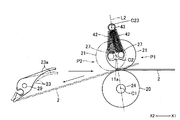
- FIG. 3 is a perspective view for explaining a configuration of a medium transport direction switching mechanism shown in FIG. 2. It is an enlarged view of the E section of FIG. It is an enlarged view of the F section of FIG. It is an enlarged view of the G section of FIG. It is a figure for demonstrating the biasing member concerning other embodiment of this invention. It is a figure for demonstrating the biasing member concerning other embodiment of this invention.
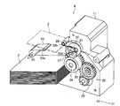
- FIG. 1 is a perspective view of a medium issuing and collecting apparatus 1 according to an embodiment of the present invention.
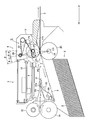
- FIG. 2 is a diagram for explaining a schematic configuration of a main part of the medium issuing and collecting apparatus 1 shown in FIG. 1 from the side.
- the medium issue / collection apparatus 1 of this embodiment includes a card issue function for issuing a card 2 as an information recording medium and a card collection function for collecting the card 2.
- the issued card 2 is discharged to the X1 direction side in FIGS.
- the X1 direction side in FIG. 1 or the like is the “front (front)” side of the medium issue / collection device 1
- the X2 direction side opposite to the X1 direction side is the “back (back) side of the medium issue / collection device 1”. ) ”Side.
- the medium issuance / recovery device 1 includes a recording / reproducing unit 3 that records information on the card 2 and reproduces information recorded on the card 2, and a card toward the recording / reproducing unit 3.
- Card sending unit 4 for sending out card 2
- card collecting unit 5 as a medium collecting unit for collecting card 2
- a transport direction switching mechanism 6 serving as a medium transport direction switching mechanism for switching the direction.
- the recording / reproducing unit 3, the card collecting unit 5, and the conveyance direction switching mechanism 6 are arranged on the front side of the medium issuing / collecting device 1, and the card sending unit 4 is arranged on the back side of the medium issuing / collecting device 1.
- the recording / reproducing unit 3 is disposed above the card collecting unit 5.
- a card transport path 7 as a medium transport path through which the card 2 is transported is formed inside the front side portion of the medium issuing and collecting apparatus 1.
- Card 2 is, for example, a rectangular vinyl chloride card having a thickness of about 0.7 to 0.8 mm.
- the card 2 in this embodiment is a non-contact type IC card, and the card 2 has a built-in communication antenna.
- a magnetic stripe may be formed on the surface of the card 2 or an IC chip may be fixed.
- the card 2 may be a PET (polyethylene terephthalate) card having a thickness of about 0.18 to 0.36 mm, a paper card having a predetermined thickness, or the like.
- the recording / reproducing unit 3 includes a communication antenna 9 and a control board 10.
- the antenna 9 and the control board 10 are fixed to a frame 11 constituting the front side portion of the medium issuing and collecting apparatus 1.
- the card collection unit 5 is a collection container for collecting the card 2, and a part of the lower end side of the frame 11 is the card collection unit 5.
- a space is formed inside the card collection unit 5, and the cards 2 collected in this space are stacked and stored.
- the card transport path 7 is formed inside the frame 11.
- the frame 11 of this embodiment is a conveyance guide that constitutes the card conveyance path 7.
- the card sending unit 4 includes a card storage unit 12 as a medium storage unit in which a plurality of cards 2 before issuance are stacked and stored in the vertical direction, and one of the plurality of cards 2 stored in the card storage unit 12.
- a pad roller 15 that is disposed opposite to the roller 14 and is urged toward the delivery roller 14 and a card separation roller for preventing the two cards 2 from being sent out from the card storage unit 12 in an overlapped state. 16 and 17.
- the card storage unit 12 is formed in a rectangular parallelepiped box shape in which a part of the side surface and the upper surface are open. Between the bottom surface portion 12a of the card storage portion 12 and the lower end of the front side wall 12b, a gate through which the card 2 stored in the card storage portion 12 passes toward the front side is formed.
- the delivery roller 13 is an eccentric roller, and the upper end side of the delivery roller 13 is disposed in a through hole formed in the bottom surface portion 12a.
- a motor (not shown) is connected to the feed roller 13.
- a motor (not shown) is connected to the feed roller 14.
- the pad roller 15 is disposed so as to face the upper end of the delivery roller 14.
- the card separation rollers 16 and 17 are disposed between the delivery roller 14 and the pad roller 15 and the card storage unit 12.
- the card separation rollers 16 and 17 are arranged so as to face each other in the vertical direction.
- the card separation roller 16 is disposed on the lower side
- the card separation roller 17 is disposed on the upper side.
- FIG. 3 is a perspective view for explaining the configuration of the medium transport direction switching mechanism 6 shown in FIG.
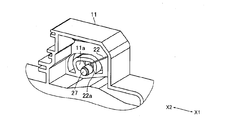
- FIG. 4 is an enlarged view of a portion E in FIG.
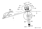
- FIG. 5 is an enlarged view of a portion F in FIG.
- FIG. 6 is an enlarged view of a portion G in FIG.
- the conveyance direction switching mechanism 6 abuts against the card 2 and conveys the card 2, a pinch roller 21 disposed opposite to the conveyance roller 20, and biases the pinch roller 21 toward the conveyance roller 20.
- the conveying roller 20 is disposed on the front side of the recording / reproducing unit 3 in the front-rear direction. As shown in FIG. 3, one gear constituting a gear train 25 is fixed to the rotary shaft 24 to which the transport roller 20 is fixed, and a motor 26 is connected to the transport roller 20 via the gear train 25. It is connected. The distance between the transport roller 20 and the delivery roller 14 in the front-rear direction is shorter than the length in the front-rear direction of the card 2 in the medium issuing and collecting apparatus 1.
- the pinch roller 21 is biased from the upper side toward the transport roller 20 by the biasing force of the torsion coil spring 22, and transports the card 2 together with the transport roller 20 with the card 2 sandwiched between the pinch roller 21 and the transport roller 20.
- the pinch roller 21 is rotatably supported by the support shaft 27.
- the frame 11 has a guide groove 11 a as a guide portion through which the support shaft 27 is inserted.
- the guide grooves 11a are formed at two locations, and both ends of the support shaft 27 are inserted into the guide grooves 11a.
- the frame 11 of this embodiment is a second holding member that holds the support shaft 27.
- the position of the pinch roller 21 when the pinch roller 21 and the conveying roller 20 face each other in the vertical direction is defined as a first facing position P ⁇ b> 1.
- the pinch roller 21 and the conveying roller are inclined in the counterclockwise direction of FIGS. 5 and 6 by the angle ⁇ (that is, in the direction inclined by the angle ⁇ toward the back side) with respect to the vertical direction.
- the guide groove 11a has the rotation center C1 of the transport roller 20 between the first facing position P1 and the second facing position P2.
- the function of guiding the support shaft 27 is achieved so that the pivoting motion of the pinch roller 21 as the center is possible.
- the guide groove 11 a is formed in a substantially rectangular shape or a substantially arc shape centered on the rotation center C ⁇ b> 1 of the conveying roller 20.
- the angle ⁇ is an acute angle. Further, the angle ⁇ is a relatively small angle, for example, about 15 ° to 20 °.
- One end of the torsion coil spring 22 (more specifically, the tip of one arm of the torsion coil spring 22) is an engagement portion 22a formed in an annular shape.
- the other end of the torsion coil spring 22 (more specifically, the tip of the other arm of the torsion coil spring 22) is an engagement portion 22b formed in an annular shape.
- both end sides of the support shaft 27 are inserted through the engagement portions 22 a, and the engagement portions 22 a are engaged with both end sides of the support shaft 27. That is, in this embodiment, the torsion coil springs 22 are disposed on both end sides of the support shaft 27.
- a fixed shaft 28 fixed to the frame 11 is inserted through the engaging portion 22b, and the engaging portion 22b is engaged with the fixed shaft 28.
- the engaging portion 22 a is rotatable relative to the support shaft 27, and the engaging portion 22 b is rotatable relative to the fixed shaft 28.
- the fixed shaft 28 in this embodiment is a first holding member that holds the torsion coil spring 22. Note that the fixed shaft 28 may be formed integrally with the frame 11.
- the fixed shaft 28 is disposed above the pinch roller 21. As shown in FIG. 6, the fixed shaft 28 has a center C ⁇ b> 2 of the support shaft 27 when the pinch roller 21 is at a substantially intermediate position between the first facing position P ⁇ b> 1 and the second facing position P ⁇ b> 2. It is fixed to the frame 11 so as to be arranged on a straight line L connecting the rotation center C1 and the center C3 of the fixed shaft 28. That is, between the first facing position P1 and the second facing position P2, the rotation center C1 of the transport roller 20, the engaging portion 22a of the torsion coil spring 22, and the engaging portion 22b are arranged in a substantially straight line.
- the pinch roller 21 and the transport roller 20 face each other, and the engaging portion 22b of the torsion coil spring 22 is inclined counterclockwise in FIG. 6 by an angle ⁇ / 2 with respect to the vertical direction. It is arranged on the straight line L.
- the pinch roller 21 is in the third facing position, the biasing force of the torsion coil spring 22 is maximized.
- the flapper 23 is disposed on the front side of the delivery roller 14.
- the flapper 23 is rotatably supported on a fixed shaft 29 fixed to the frame 11. Further, the flapper 23 is formed with a closing portion 23 a that closes the transport path R ⁇ b> 1 of the card 2 heading forward from the card sending portion 4 so as to protrude substantially obliquely upward from the fixed shaft 29.
- the flapper 23 is supported by a fixed shaft 29 so that the flapper 23 can be rotated.
- the flapper 23 is biased by a biasing member (not shown) or by its own weight in a direction in which the closing portion 23a closes the transport path R1 (that is, counterclockwise in FIG. 5).
- the transport path R1 of the present embodiment is a first transport path.
- the transport roller 20 rotates in the clockwise direction in FIG. Further, when the card 2 is sent out from the card sending part 4, the card 2 comes into contact with the upper surface side of the closing part 23a, and the closing part 23a opens the transport path R1 as shown by a two-dot chain line in FIG. Rotate to position. That is, when the transport roller 20 is rotating in the clockwise direction of FIG. 5, the card 2 comes into contact with the upper surface side of the closing portion 23a, and the flapper 23 opens the transport path R1.
- the pinch roller 21 is moved to the outer periphery of the conveyance roller 20.
- a force for moving the pinch roller 21 along the surface to the first facing position P1 and passing the third facing position at the second facing position P2, friction between the pinch roller 21 and the support shaft 27 The friction coefficient between the conveying roller 20 and the pinch roller 21, the biasing force of the torsion coil spring 22, the angle ⁇ , and the like so that the force and the frictional force between the conveying roller 20 and the pinch roller 21 increase in this order. Is set.
- the pinch roller 21 in the second facing position P2 moves to the first facing position P1
- the pinch roller 21 is moved from the second facing position P2 to the third facing position by a frictional force between the conveying roller 20 and the pinch roller 21.
- the pinch roller 21 passes through the third facing position
- the pinch roller 21 moves to the first facing position P1 mainly by the urging force of the torsion coil spring 22. That is, the pinch roller 21 moves from the second facing position P2 to the first facing position P1 using a so-called toggle motion with the third facing position as a toggle point.
- the pinch roller 21 hardly rotates around the support shaft 27 while moving from the second opposing position P2 to the first opposing position P1, and after moving to the first opposing position P1, the support shaft Rotate around 27.
- the pinch roller 21 When the pinch roller 21 is at the first facing position P1, the pinch roller 21 is held at the first facing position P1 by the biasing force of the torsion coil spring 22, and the card 2 is conveyed when the card 2 is issued.
- the pinch roller 21 and the transport roller 20 are opposed to each other in a direction substantially orthogonal to the front-rear direction (ie, the vertical direction).
- the card 2 in which the back end of the card 2 is arranged in front of the closing portion 23a is sandwiched between the pinch roller 21 and the transport roller 20 at the first facing position P1.
- the pinch roller 21 moves to the second facing position P2 along the outer peripheral surface of the conveying roller 20 and is in the first facing position P1.
- the force for passing the third opposing position, the frictional force between the pinch roller 21 and the support shaft 27, and the frictional force between the conveying roller 20 and the pinch roller 21 are increased in this order.
- the friction coefficient of the conveying roller 20 and the pinch roller 21, the biasing force of the torsion coil spring 22, the angle ⁇ , and the like are set.
- the pinch roller 21 at the first facing position P1 moves to the second facing position P2
- the first frictional force between the conveying roller 20 and the card 2 and the frictional force between the pinch roller 21 and the card 2 are the first.
- the pinch roller 21 moves to the second facing position P2 mainly by the biasing force of the torsion coil spring 22. That is, the pinch roller 21 moves from the first facing position P1 to the second facing position P2 using a toggle motion with the third facing position as a toggle point.
- the pinch roller 21 hardly rotates around the support shaft 27 while moving from the first facing position P1 to the second facing position P2, and after moving to the second facing position P2, the support shaft Rotate around 27.
- the pinch roller 21 is held at the second facing position P2 by the urging force of the torsion coil spring 22, and the card collecting unit 5 collects the card 2
- the pinch roller 21 and the transport roller 20 are opposed to each other in a direction substantially orthogonal to the transport direction of the card 2.
- the transport roller 20 when the transport roller 20 is rotated counterclockwise in FIG. 5 while being sandwiched between the pinch roller 21 and the transport roller 20, the back surface of the card 2 is placed on the lower surface of the closing portion 23a that closes the transport path R1. The end abuts.
- the elastic force of the card 2 causes the moment in the counterclockwise direction of FIG. 5 with the contact portion between the closing portion 23a and the card 2 as a fulcrum. 2 occurs on the front end side.
- the moment generated on the front end side of the card 2 assists the movement of the pinch roller 21 holding the card 2 between the card 2 and the second opposing position P2.
- the flapper 23 of the present embodiment functions to guide the card 2 so that the pinch roller 21 moves to the second facing position P2.
- the flapper 23 is arranged so that the back end side of the card 2 does not contact the lower surface of the closing portion 23a.
- the pinch roller 21 rotates around the rotation center C1 of the transport roller 20 and moves to the first facing position P1 or the second facing position P2, it is inclined with respect to the front-rear direction.
- the conveyance direction of the card 2 is switched between the diagonal direction and the front-rear direction.
- the pinch roller 21 passes through the third facing position by utilizing the counterclockwise moment of FIG. 5 generated on the front end side of the card 2 after the back end of the card 2 abuts the lower surface of the closing portion 23a.
- the friction coefficient of the conveying roller 20 and the pinch roller 21, the biasing force of the torsion coil spring 22, the angle ⁇ , and the like may be set. That is, when the conveying roller 20 rotates counterclockwise in FIG. 5, the pinch roller depends only on the frictional force between the conveying roller 20 and the card 2 and the frictional force between the pinch roller 21 and the card 2.
- the friction coefficient of the conveying roller 20 and the pinch roller 21 and the torsion coil spring are set so that the pinch roller 21 can pass through the third facing position. 22 urging forces, angles ⁇ , and the like may be set.
- a concave portion 11 b that is recessed upward is formed on the upper surface of the card transport path 7 in front of the transport roller 20 and the pinch roller 21.
- the recess 11 b is formed in the frame 11.
- the concave portion 11b is formed so that the conveyance roller 20 rotates counterclockwise in FIG. 5 with the card 2 sandwiched between the conveyance roller 20 and the pinch roller 21, and the pinch roller 21 is moved from the first facing position P1 to the first position. 2 When it moves to the opposing position P2, it becomes an escape part for preventing the contact between the card 2 and the frame 11.
- the recording roller 4 and the pad roller 15 are used to transfer the recording / reproducing unit 3 and the conveyance direction switching mechanism by the transmission rollers 13, 14 and the pad roller 15.
- the card 2 is sent to 6.
- the sent card 2 is temporarily stopped below the recording / reproducing unit 3. At this time, the front end side of the card 2 is sandwiched between the transport roller 20 and the pinch roller 21, and the back end side of the card 2 is sandwiched between the delivery roller 14 and the pad roller 15.
- the transport roller 20 rotates in the reverse direction after the transport roller 20 rotates forward until the back end of the card 2 is arranged in front of the closing portion 23a.
- the pinch roller 21 that was in the first facing position P1 moves to the second facing position P2.
- the back end of the card 2 comes into contact with the lower surface of the closing portion 23a, and the movement of the pinch roller 21 to the second facing position P2 is assisted.
- the pinch roller 21 moves to the second facing position P2
- the card 2 is transported between the transport roller 20 and the pinch roller 21 until the front end of the card 2 comes off, and between the transport roller 20 and the pinch roller 21.
- the card 2 is collected by the card collection unit 5.
- the next card 2 is sent from the card sending unit 4.
- the pinch roller 21 that was in the first facing position P1 moves to the second facing position P2.
- the transport roller 20 rotates forward or backward based on the reproduction result in the recording / reproducing unit 3. If the user forgets to take out the issued card 2, the transport roller 20 rotates in the reverse direction, and the card 2 is collected by the card collection unit 5.
- the transport direction of the card 2 to be transported can be switched with a simple configuration using the torsion coil spring 22. Further, in this embodiment, since the configuration of the transport direction switching mechanism 6 can be simplified, the configuration of the medium issuing / collecting apparatus 1 can be simplified. Therefore, it is possible to reduce the size of the medium issue / collection apparatus 1.
- the third facing position serving as the toggle point is at a substantially intermediate position between the first facing position P1 and the second facing position P2. Therefore, compared with the case where the third facing position is biased toward the first facing position P1 or the second facing position P2, the transport for moving the pinch roller 21 from the first facing position P1 to the third facing position.
- the friction coefficient of the roller 20 and the pinch roller 21, the biasing force of the torsion coil spring 22, and the like, and the friction of the conveying roller 20 and the pinch roller 21 for moving the pinch roller 21 from the second facing position P2 to the third facing position Setting of the coefficient, the urging force of the torsion coil spring 22 and the like becomes easy. Therefore, in this embodiment, it becomes easy to move the pinch roller 21 between the first facing position P1 and the second facing position P2.
- the flapper 23 functions to guide the card 2 so that the pinch roller 21 moves to the second facing position P2. Therefore, it becomes easy to move the pinch roller 21 from the first facing position P1 to the second facing position P2 using the flapper 23.
- the conveyance roller 20 rotates in the reverse direction while the card 2 is sandwiched between the conveyance roller 20 and the pinch roller 21, and the pinch roller 21 moves from the first opposed position P1 to the second opposed position P2.
- the frame 11 is formed with a recess 11b for preventing contact between the card 2 and the frame 11. Therefore, it becomes easy to move the pinch roller 21 from the first facing position P1 to the second facing position P2.
- the transport direction of the card 2 is switched. Further, when the pinch roller 21 moves to the second facing position P2, the flapper 23 is disposed so that the back end side of the card 2 does not come into contact with the lower surface of the closing portion 23a. Therefore, the card 2 sandwiched between the pinch roller 21 and the transport roller 20 hardly bends when the transport direction of the card 2 is switched and after the transport direction of the card 2 is switched. Therefore, in this embodiment, it is possible to prevent damage to the antenna built in the card 2 due to the bending stress of the card 2.
- guide grooves 11a are formed on both end sides of the support shaft 27. Further, the torsion coil springs 22 are disposed on both ends of the support shaft 27, respectively. Therefore, the support shaft 27 can be moved in a well-balanced manner between the first opposed position P1 and the second opposed position P2 by the guide grooves 11a and the torsion coil springs 22 arranged on both ends of the support shaft 27. Thus, the support shaft 27 can be easily moved.
- the biasing member that biases the pinch roller 21 toward the transport roller 20 is the torsion coil spring 22.
- the urging member for urging the pinch roller 21 toward the conveying roller 20 may be a tension coil spring 32 as shown in FIG.
- one end of the tension coil spring 32 is attached to the support shaft 27 so as to be relatively rotatable, and the other end of the tension coil spring 32 is fixed to the frame 11 below the transport roller 20.
- the fixed shaft 33 has a center C2 of the support shaft 27 when the pinch roller 21 is at a substantially intermediate position between the first facing position P1 and the second facing position P2. It is fixed to the frame 11 so as to be arranged on a straight line L1 connecting the center C13.
- the urging member that urges the pinch roller 21 toward the conveying roller 20 may be a compression coil spring 42 as shown in FIG.
- one end of the compression coil spring 42 abuts on the support shaft 27, and the other end of the compression coil spring 42 is on a fixed shaft 43 as a first holding member fixed to the frame 11 above the pinch roller 21. Attached so as to be relatively rotatable.
- the fixed shaft 43 has a center C2 of the support shaft 27 when the pinch roller 21 is at a substantially intermediate position between the first facing position P1 and the second facing position P2, and the rotation center C1 of the transport roller 20 and the fixed shaft 43. It is fixed to the frame 11 so as to be arranged on a straight line L2 connecting the center C23 of the frame.
- the urging member is the compression coil spring 42, a guide part for preventing the compression coil spring 42 from buckling is required.
- the urging member that urges the pinch roller 21 toward the conveying roller 20 may be another spring member or an elastic member such as rubber.
- the support shaft 27 that supports the pinch roller 21 is held by the frame 11.
- the support shaft 27 may be held by a lever member that can rotate around the rotation center C ⁇ b> 1 of the transport roller 20.
- the support shaft 27 is fixed to one end side of the lever member, and the other end side of the lever member is rotatably held by the rotation shaft 24.
- the side surface of the lever member and the side surface of the conveying roller 20 may be brought into press contact.
- the lever member is moved between the first facing position P1 and the second facing position P2 by the support shaft 27 inserted into the guide groove 11a and the guide groove 11a.
- the rotation range of the lever member may be restricted so as to rotate, or the rotation range of the lever member is set so that the lever member rotates between the first facing position P1 and the second facing position P2.
- a stopper member for regulating may be provided.
- the lever member serves as a second holding member that holds the support shaft 27.
- the rotation center C1 of the transport roller 20, the engaging portion 22a of the torsion coil spring 22, and the engaging portion 22b are substantially straight at a substantially intermediate position between the first opposing position P1 and the second opposing position P2.
- There is a third facing position where the pinch roller 21 and the conveying roller 20 face each other so as to be arranged in a shape.
- the third facing position may be biased toward the first facing position P1 or may be biased toward the second facing position P2.
- the third facing position may coincide with the first facing position P1 or the second facing position P2.
- the pinch roller 21 becomes unstable at the first facing position P1, and easily returns to the second facing position P2.
- the pinch roller 21 becomes unstable at the second facing position P2, and easily returns to the first facing position P1.
- the torsion coil spring 22 can be set in the same manner as described above by appropriately setting the friction coefficient of the conveying roller 20 and the pinch roller 21, the urging force of the torsion coil spring 22, the angle ⁇ , and the like. It is possible to obtain an effect that the transport direction of the card 2 to be transported can be switched with a simple configuration using.
- a straight line L connecting the rotation center C1 of the transport roller 20 and the center C3 of the fixed shaft 28 is the center C2 of the support shaft 27 and the rotation center C1 of the transport roller 20 when the pinch roller 21 is at the first facing position P1.
- the fixed shaft 28 may be fixed to the frame 11 so as to be arranged on the clockwise side of FIG.
- the pinch roller 21 is biased toward the second facing position P ⁇ b> 2 by the biasing force of the torsion coil spring 22.
- the pinch roller 21 at the second facing position P2 moves to the first facing position P1.
- a straight line L connecting the rotation center C1 of the transport roller 20 and the center C3 of the fixed shaft 28 is the center C2 of the support shaft 27 and the rotation center C1 of the transport roller 20 when the pinch roller 21 is at the second facing position P2.
- the fixed shaft 28 may be fixed to the frame 11 so as to be arranged on the counterclockwise side of FIG. In this case, the pinch roller 21 is urged toward the first facing position P ⁇ b> 1 by the urging force of the torsion coil spring 22. In this case, when the transport roller 20 rotates in the reverse direction, the pinch roller 21 at the first facing position P1 moves to the second facing position P2.
- the torsion coil spring 22 can be used in the same manner as described above by appropriately setting the friction coefficient of the conveying roller 20 and the pinch roller 21, the urging force of the torsion coil spring 22, the angle ⁇ , and the like. With this simple configuration, it is possible to obtain an effect that the transport direction of the card 2 to be transported can be switched.
- the transport direction switching mechanism 6 includes the flapper 23.
- the pinch roller 21 reliably moves to the second facing position P2, and the card 2 is recovered.
- the transport direction switching mechanism 6 may not include the flapper 23 as long as it can be reliably collected into the unit 5.
- the pinch roller 21 is rotatably supported by the support shaft 27.
- the pinch roller 21 may be fixed to a rotating shaft that rotates together with the pinch roller 21, or the rotating shaft that rotates together with the pinch roller 21 and the pinch roller 21 may be integrally formed.
- a bearing that rotatably supports the rotating shaft is held by the frame 11.
- one end of the torsion coil spring 22 is engaged with the bearing, and a guide portion for guiding the bearing between the first facing position P1 and the second facing position P2 is formed on the frame 11. .
- the medium issuing / collecting apparatus 1 collects the card 2 sent from the card sending unit 4 as necessary.
- the medium issuing and collecting apparatus 1 may collect the card 2 inserted from the outside as needed.
- the recording / reproducing unit 3 includes the communication antenna 9.
- the recording / reproducing unit 3 replaces the antenna 9 or in addition to the antenna 9 with a magnetic head and / or IC. A contact may be provided.
- the configuration of the transport direction switching mechanism 6 according to the embodiment of the present invention has been described by taking the medium issuing / collecting apparatus 1 having the card 2 issuing function and the recovery function as an example.
- the present invention can be used in various devices that require switching of the card 2 conveyance direction.
Landscapes
- Engineering & Computer Science (AREA)
- Mechanical Engineering (AREA)
- Physics & Mathematics (AREA)
- General Physics & Mathematics (AREA)
- Theoretical Computer Science (AREA)
- Delivering By Means Of Belts And Rollers (AREA)
- Conveying Record Carriers (AREA)
- Separation, Sorting, Adjustment, Or Bending Of Sheets To Be Conveyed (AREA)
Abstract
Description
図1は、本発明の実施の形態にかかる媒体発行回収装置1の斜視図である。図2は、図1に示す媒体発行回収装置1の要部の概略構成を側面から説明するための図である。
図3は、図2に示す媒体搬送方向切替機構6の構成を説明するための斜視図である。図4は、図1のE部の拡大図である。図5は、図2のF部の拡大図である。図6は、図5のG部の拡大図である。
以上のように構成された媒体発行回収装置1でのカード2の発行動作および回収動作の概略を以下に説明する。以下の説明では、図5の時計方向への搬送ローラ20の回転を正回転、図5の反時計方向への搬送ローラ20の回転を逆回転とする。
以上説明したように、本形態では、搬送ローラ20が正回転すると、第2対向位置P2にあったピンチローラ21は第1対向位置P1へ移動し、ネジリコイルバネ22の付勢力によって、第1対向位置P1で保持される。また、搬送ローラ20が逆回転すると、第1対向位置P1にあったピンチローラ21は、第2対向位置P2へ移動し、ネジリコイルバネ22の付勢力によって、第2対向位置P2で保持される。また、本形態では、第1対向位置P1または第2対向位置P2へピンチローラ21が移動すると、搬送ローラ20とピンチローラ21とによって搬送されるカード2の搬送方向が切り替わる。したがって、本形態では、ネジリコイルバネ22を用いた簡易な構成で、搬送されるカード2の搬送方向を切り替えることができる。また、本形態では、搬送方向切替機構6の構成を簡素化できるため、媒体発行回収装置1の構成を簡素化することが可能になる。したがって、媒体発行回収装置1を小型化することが可能になる。
上述した形態は、本発明の好適な形態の一例ではあるが、これに限定されるものではなく本発明の要旨を変更しない範囲において種々変形実施が可能である。
2 カード(情報記録媒体)
3 記録再生部
5 カード回収部(媒体回収部)
6 搬送方向切替機構(媒体搬送方向切替機構)
7 カード搬送路(媒体搬送路)
11 フレーム(第2保持部材、搬送ガイド)
11a ガイド溝(ガイド部)
11b 凹部(逃げ部)
12 カード収納部(媒体収納部)
20 搬送ローラ
21 ピンチローラ
22 ネジリコイルバネ(付勢部材)
23 フラッパ(振分部材)
27 支持軸
28、33、43 固定軸(第1保持部材)
32 引張りコイルバネ(付勢部材)
42 圧縮コイルバネ(付勢部材)
C1 搬送ローラの回転中心
P1 第1対向位置
P2 第2対向位置
R1 搬送経路(第1搬送経路)
Claims (10)
- 搬送される情報記録媒体の搬送方向を切り替える媒体搬送方向切替機構において、
前記情報記録媒体に当接して前記情報記録媒体を搬送する搬送ローラと、前記搬送ローラに対向配置され前記搬送ローラとの間に前記情報記録媒体を挟んで前記搬送ローラとともに前記情報記録媒体を搬送するピンチローラと、前記搬送ローラに向かって前記ピンチローラを付勢する付勢部材と、前記ピンチローラとともに回転する回転軸を回転可能に支持する軸受または前記ピンチローラを回転可能に支持する支持軸と、前記付勢部材を保持する第1保持部材とを備えるとともに、
所定の第1方向で前記ピンチローラと前記搬送ローラとが対向する第1対向位置と、前記第1方向に対して傾斜する所定の第2方向で前記ピンチローラと前記搬送ローラとが対向する第2対向位置との間で、前記搬送ローラの回転中心を中心とする前記ピンチローラの回動動作が可能となるように、前記支持軸または前記軸受を保持する第2保持部材を備え、
前記付勢部材の一端は、前記支持軸または前記軸受に係合し、前記付勢部材の他端は、前記第1保持部材に係合し、
前記搬送ローラが正回転すると、前記第2対向位置にある前記ピンチローラは前記第1対向位置へ移動し、前記搬送ローラが逆回転すると、前記第1対向位置にある前記ピンチローラは前記第2対向位置へ移動することを特徴とする媒体搬送方向切替機構。 - 前記第1対向位置と前記第2対向位置との間には、前記搬送ローラの回転中心と前記付勢部材の一端と前記付勢部材の他端とが略一直線状に配置されるように前記ピンチローラと前記搬送ローラとが対向する第3対向位置があることを特徴とする請求項1記載の媒体搬送方向切替機構。
- 前記第3対向位置は、前記第1対向位置と前記第2対向位置との略中間位置にあることを特徴とする請求項2記載の媒体搬送方向切替機構。
- 前記第2保持部材には、前記第1対向位置と前記第2対向位置との間で、前記搬送ローラの回転中心を中心とする前記ピンチローラの回動動作が可能となるように、前記支持軸または前記軸受を案内するガイド部が形成され、
前記第1保持部材は、前記第2保持部材に固定されている、または、第2保持部材と一体で形成されていることを特徴とする請求項1から3のいずれかに記載の媒体搬送方向切替機構。 - 前記ガイド部は、前記支持軸または前記回転軸の両端側に形成されていることを特徴とする請求項4記載の媒体搬送方向切替機構。
- 前記搬送ローラの逆回転時に、前記搬送ローラと前記ピンチローラとの間に挟まれた前記情報記録媒体の、搬送方向の端部が当接可能で、かつ、前記第2対向位置へ前記ピンチローラが移動するように前記情報記録媒体を案内する振分部材を備えることを特徴とする請求項1から5のいずれかに記載の媒体搬送方向切替機構。
- 前記振分部材は、前記搬送ローラが正回転しているときの前記情報記録媒体の搬送経路となる第1搬送経路を塞ぐ位置と前記第1搬送経路を開放する位置との間で回動可能であるとともに、前記第1搬送経路を塞ぐ方向に付勢され、
前記搬送ローラが正回転しているときに前記情報記録媒体が前記振分部材に当接して、前記振分部材が前記第1搬送経路を開放することを特徴とする請求項6記載の媒体搬送方向切替機構。 - 前記情報記録媒体が搬送される媒体搬送路を構成する搬送ガイドを備え、
前記搬送ガイドには、前記搬送ローラと前記ピンチローラとの間に前記情報記録媒体が挟まれた状態で前記ピンチローラが前記第1対向位置と前記第2対向位置との間を移動したときに、前記情報記録媒体と前記搬送ガイドとの接触を防止するための逃げ部が形成されていることを特徴とする請求項1から7のいずれかに記載の媒体搬送方向切替機構。 - 請求項1から8のいずれかに記載の媒体搬送方向切替機構と、前記媒体搬送方向切替機構に向かって送出される前記情報記録媒体が収納される媒体収納部と、前記情報記録媒体が回収される媒体回収部とを備え、
前記搬送ローラが正回転すると前記媒体収納部から送出された前記情報記録媒体が発行され、前記搬送ローラが逆回転すると前記媒体回収部に前記情報記録媒体が回収されることを特徴とする媒体発行回収装置。 - 前記媒体収納部から送出される前記情報記録媒体への情報の記録および前記情報記録媒体に記録された情報の再生を行う記録再生部を備え、
前記搬送ローラは、前記記録再生部での再生結果に基づいて正回転または逆回転することを特徴とする請求項9記載の媒体発行回収装置。
Priority Applications (2)
| Application Number | Priority Date | Filing Date | Title |
|---|---|---|---|
| CN201180029401.4A CN102959562B (zh) | 2010-07-05 | 2011-07-01 | 介质搬运方向切换机构及介质发行回收装置 |
| US13/808,332 US8998206B2 (en) | 2010-07-05 | 2011-07-01 | Medium feeding direction switching mechanism and medium issuing and collecting device |
Applications Claiming Priority (2)
| Application Number | Priority Date | Filing Date | Title |
|---|---|---|---|
| JP2010-152606 | 2010-07-05 | ||
| JP2010152606A JP5523225B2 (ja) | 2010-07-05 | 2010-07-05 | 媒体搬送方向切替機構および媒体発行回収装置 |
Publications (1)
| Publication Number | Publication Date |
|---|---|
| WO2012005177A1 true WO2012005177A1 (ja) | 2012-01-12 |
Family
ID=45441156
Family Applications (1)
| Application Number | Title | Priority Date | Filing Date |
|---|---|---|---|
| PCT/JP2011/065146 Ceased WO2012005177A1 (ja) | 2010-07-05 | 2011-07-01 | 媒体搬送方向切替機構および媒体発行回収装置 |
Country Status (4)
| Country | Link |
|---|---|
| US (1) | US8998206B2 (ja) |
| JP (1) | JP5523225B2 (ja) |
| CN (1) | CN102959562B (ja) |
| WO (1) | WO2012005177A1 (ja) |
Families Citing this family (11)
| Publication number | Priority date | Publication date | Assignee | Title |
|---|---|---|---|---|
| JP2015169982A (ja) * | 2014-03-05 | 2015-09-28 | 株式会社マースウインテック | カード発行装置 |
| WO2016031026A1 (ja) | 2014-08-28 | 2016-03-03 | 富士通フロンテック株式会社 | 搬送装置 |
| JP6225872B2 (ja) * | 2014-10-06 | 2017-11-08 | 京セラドキュメントソリューションズ株式会社 | シート搬送装置及び画像形成装置 |
| US9550647B1 (en) * | 2015-10-14 | 2017-01-24 | Xerox Corporation | Self-setting exit roll assembly |
| JP6696873B2 (ja) * | 2016-09-30 | 2020-05-20 | 日本電産サンキョー株式会社 | カード処理装置 |
| JP6737677B2 (ja) * | 2016-09-30 | 2020-08-12 | 日本電産サンキョー株式会社 | カード発行装置 |
| JP6879005B2 (ja) * | 2017-03-29 | 2021-06-02 | セイコーエプソン株式会社 | 搬送装置、記録装置及び搬送方法 |
| JP2019100478A (ja) * | 2017-12-05 | 2019-06-24 | 富士ゼロックス株式会社 | 回転部の支持構造、搬送装置、帯電装置および画像形成装置 |
| CN109117899B (zh) * | 2018-08-01 | 2021-08-27 | 长城信息股份有限公司 | 介质自助发放设备 |
| EP3623327B1 (de) * | 2018-09-11 | 2021-07-07 | Frama AG | Verfahren zum frankieren von auf einer förderstrecke einer frankiermaschine zugeführten versandstücken, und dazugehörige einrichtung |
| EP3693306B1 (de) * | 2019-02-11 | 2021-09-15 | Frama AG | Verfahren zum frankieren von einer frankiermaschine zugeführten versandstücken, und einrichtung zur durchführung des verfahrens |
Citations (4)
| Publication number | Priority date | Publication date | Assignee | Title |
|---|---|---|---|---|
| JPH08227442A (ja) * | 1995-02-21 | 1996-09-03 | Sankyo Seiki Mfg Co Ltd | カード往復搬送装置 |
| JPH11338980A (ja) * | 1998-05-28 | 1999-12-10 | Asahi Seiko Co Ltd | Icカードの発行装置 |
| JP2002032717A (ja) * | 2000-05-05 | 2002-01-31 | Asahi Seiko Kk | メモリカードのハンドリング装置 |
| JP2008257278A (ja) * | 2007-03-30 | 2008-10-23 | Citizen Holdings Co Ltd | メディア識別装置 |
Family Cites Families (8)
| Publication number | Priority date | Publication date | Assignee | Title |
|---|---|---|---|---|
| US4256299A (en) * | 1979-07-18 | 1981-03-17 | Minnesota Mining And Manufacturing Company | Multiple sheet sensor and deflector |
| JP2802078B2 (ja) * | 1988-09-09 | 1998-09-21 | オリンパス光学工業株式会社 | 用紙搬送案内装置 |
| US5723825A (en) * | 1996-04-01 | 1998-03-03 | Pitney Bowes Inc. | Transport apparatus for a weighing module |
| TW426630B (en) * | 1998-05-28 | 2001-03-21 | Asahi Seiko Co Ltd | IC card processing machine |
| US6186501B1 (en) * | 1998-09-24 | 2001-02-13 | Heidelberger Druckmaschinen Ag | Signature diverter |
| TWI252837B (en) * | 2005-03-11 | 2006-04-11 | Lite On Technology Corp | Paper feeding device and method for flipping paper for same |
| JP5007171B2 (ja) * | 2007-02-13 | 2012-08-22 | 三菱電機株式会社 | 薄膜トランジスタアレイ基板、その製造方法、及び表示装置 |
| CN104097965A (zh) * | 2013-04-11 | 2014-10-15 | 致伸科技股份有限公司 | 纸张传送用的偏向滚轮装置及改变纸张传送路径的方法 |
-
2010
- 2010-07-05 JP JP2010152606A patent/JP5523225B2/ja not_active Expired - Fee Related
-
2011
- 2011-07-01 US US13/808,332 patent/US8998206B2/en not_active Expired - Fee Related
- 2011-07-01 WO PCT/JP2011/065146 patent/WO2012005177A1/ja not_active Ceased
- 2011-07-01 CN CN201180029401.4A patent/CN102959562B/zh not_active Expired - Fee Related
Patent Citations (4)
| Publication number | Priority date | Publication date | Assignee | Title |
|---|---|---|---|---|
| JPH08227442A (ja) * | 1995-02-21 | 1996-09-03 | Sankyo Seiki Mfg Co Ltd | カード往復搬送装置 |
| JPH11338980A (ja) * | 1998-05-28 | 1999-12-10 | Asahi Seiko Co Ltd | Icカードの発行装置 |
| JP2002032717A (ja) * | 2000-05-05 | 2002-01-31 | Asahi Seiko Kk | メモリカードのハンドリング装置 |
| JP2008257278A (ja) * | 2007-03-30 | 2008-10-23 | Citizen Holdings Co Ltd | メディア識別装置 |
Also Published As
| Publication number | Publication date |
|---|---|
| US20140145396A1 (en) | 2014-05-29 |
| JP2012012203A (ja) | 2012-01-19 |
| US8998206B2 (en) | 2015-04-07 |
| CN102959562B (zh) | 2015-11-25 |
| JP5523225B2 (ja) | 2014-06-18 |
| CN102959562A (zh) | 2013-03-06 |
Similar Documents
| Publication | Publication Date | Title |
|---|---|---|
| JP5523225B2 (ja) | 媒体搬送方向切替機構および媒体発行回収装置 | |
| CN103787099B (zh) | 被记录介质盒、被记录介质输送装置、记录装置 | |
| CN103935787A (zh) | 介质供给装置 | |
| CN102089771B (zh) | 卡处理单元及发卡装置 | |
| JP5563400B2 (ja) | 媒体重送防止機構および媒体送出装置 | |
| WO2018167934A1 (ja) | 媒体搬送装置 | |
| JP6552603B2 (ja) | Icカードリーダ | |
| JP2008165483A (ja) | カード回収機構およびカード発行装置 | |
| JP2018190242A (ja) | 媒体処理装置 | |
| JPS6057112B2 (ja) | 磁気カ−ド搬送装置 | |
| JP4559873B2 (ja) | カード状媒体搬送機構 | |
| JP5462100B2 (ja) | 冊子媒体取扱装置 | |
| JP2586727Y2 (ja) | 通帳取込み機構 | |
| CN101898700B (zh) | 卡片状介质的输送机构 | |
| JP4309860B2 (ja) | カード状媒体搬送機構 | |
| KR101253406B1 (ko) | 책자 매체 취급 장치 | |
| JP5677886B2 (ja) | カードスタッカを備えたカード処理装置 | |
| JP2012159906A (ja) | 収納カード繰り出し機構を備えたカード処理装置 | |
| JP2005196375A (ja) | カードリーダ | |
| JPS62254284A (ja) | カ−ド搬送装置 | |
| JP4136873B2 (ja) | 紙幣収納装置 | |
| JP4882907B2 (ja) | シート状媒体収納装置 | |
| EP3483101A1 (en) | Medium processing device | |
| JP5314340B2 (ja) | カード処理ユニットおよびカード発行装置 | |
| JPS60193695A (ja) | 通帳改頁機構 |
Legal Events
| Date | Code | Title | Description |
|---|---|---|---|
| WWE | Wipo information: entry into national phase |
Ref document number: 201180029401.4 Country of ref document: CN |
|
| 121 | Ep: the epo has been informed by wipo that ep was designated in this application |
Ref document number: 11803511 Country of ref document: EP Kind code of ref document: A1 |
|
| NENP | Non-entry into the national phase |
Ref country code: DE |
|
| WWE | Wipo information: entry into national phase |
Ref document number: 13808332 Country of ref document: US |
|
| 122 | Ep: pct application non-entry in european phase |
Ref document number: 11803511 Country of ref document: EP Kind code of ref document: A1 |