WO2012005105A1 - 板状体の梱包構造及び板状体搬送方法 - Google Patents
板状体の梱包構造及び板状体搬送方法 Download PDFInfo
- Publication number
- WO2012005105A1 WO2012005105A1 PCT/JP2011/064087 JP2011064087W WO2012005105A1 WO 2012005105 A1 WO2012005105 A1 WO 2012005105A1 JP 2011064087 W JP2011064087 W JP 2011064087W WO 2012005105 A1 WO2012005105 A1 WO 2012005105A1
- Authority
- WO
- WIPO (PCT)
- Prior art keywords
- plate
- container
- packing
- packing unit
- lashing belt
- Prior art date
- Legal status (The legal status is an assumption and is not a legal conclusion. Google has not performed a legal analysis and makes no representation as to the accuracy of the status listed.)
- Ceased
Links
Images







Classifications
-
- B—PERFORMING OPERATIONS; TRANSPORTING
- B65—CONVEYING; PACKING; STORING; HANDLING THIN OR FILAMENTARY MATERIAL
- B65D—CONTAINERS FOR STORAGE OR TRANSPORT OF ARTICLES OR MATERIALS, e.g. BAGS, BARRELS, BOTTLES, BOXES, CANS, CARTONS, CRATES, DRUMS, JARS, TANKS, HOPPERS, FORWARDING CONTAINERS; ACCESSORIES, CLOSURES, OR FITTINGS THEREFOR; PACKAGING ELEMENTS; PACKAGES
- B65D21/00—Nestable, stackable or joinable containers; Containers of variable capacity
- B65D21/02—Containers specially shaped, or provided with fittings or attachments, to facilitate nesting, stacking, or joining together
-
- B—PERFORMING OPERATIONS; TRANSPORTING
- B65—CONVEYING; PACKING; STORING; HANDLING THIN OR FILAMENTARY MATERIAL
- B65D—CONTAINERS FOR STORAGE OR TRANSPORT OF ARTICLES OR MATERIALS, e.g. BAGS, BARRELS, BOTTLES, BOXES, CANS, CARTONS, CRATES, DRUMS, JARS, TANKS, HOPPERS, FORWARDING CONTAINERS; ACCESSORIES, CLOSURES, OR FITTINGS THEREFOR; PACKAGING ELEMENTS; PACKAGES
- B65D19/00—Pallets or like platforms, with or without side walls, for supporting loads to be lifted or lowered
- B65D19/38—Details or accessories
- B65D19/385—Frames, corner posts or pallet converters, e.g. for facilitating stacking of charged pallets
-
- B—PERFORMING OPERATIONS; TRANSPORTING
- B65—CONVEYING; PACKING; STORING; HANDLING THIN OR FILAMENTARY MATERIAL
- B65D—CONTAINERS FOR STORAGE OR TRANSPORT OF ARTICLES OR MATERIALS, e.g. BAGS, BARRELS, BOTTLES, BOXES, CANS, CARTONS, CRATES, DRUMS, JARS, TANKS, HOPPERS, FORWARDING CONTAINERS; ACCESSORIES, CLOSURES, OR FITTINGS THEREFOR; PACKAGING ELEMENTS; PACKAGES
- B65D19/00—Pallets or like platforms, with or without side walls, for supporting loads to be lifted or lowered
- B65D19/0004—Rigid pallets without side walls
- B65D19/0006—Rigid pallets without side walls the load supporting surface being made of a single element
- B65D19/0008—Rigid pallets without side walls the load supporting surface being made of a single element forming a continuous plane contact surface
- B65D19/001—Rigid pallets without side walls the load supporting surface being made of a single element forming a continuous plane contact surface the base surface being made of a single element
- B65D19/0012—Rigid pallets without side walls the load supporting surface being made of a single element forming a continuous plane contact surface the base surface being made of a single element forming a continuous plane contact surface
-
- B—PERFORMING OPERATIONS; TRANSPORTING
- B65—CONVEYING; PACKING; STORING; HANDLING THIN OR FILAMENTARY MATERIAL
- B65D—CONTAINERS FOR STORAGE OR TRANSPORT OF ARTICLES OR MATERIALS, e.g. BAGS, BARRELS, BOTTLES, BOXES, CANS, CARTONS, CRATES, DRUMS, JARS, TANKS, HOPPERS, FORWARDING CONTAINERS; ACCESSORIES, CLOSURES, OR FITTINGS THEREFOR; PACKAGING ELEMENTS; PACKAGES
- B65D19/00—Pallets or like platforms, with or without side walls, for supporting loads to be lifted or lowered
- B65D19/02—Rigid pallets with side walls, e.g. box pallets
- B65D19/06—Rigid pallets with side walls, e.g. box pallets with bodies formed by uniting or interconnecting two or more components
-
- B—PERFORMING OPERATIONS; TRANSPORTING
- B65—CONVEYING; PACKING; STORING; HANDLING THIN OR FILAMENTARY MATERIAL
- B65D—CONTAINERS FOR STORAGE OR TRANSPORT OF ARTICLES OR MATERIALS, e.g. BAGS, BARRELS, BOTTLES, BOXES, CANS, CARTONS, CRATES, DRUMS, JARS, TANKS, HOPPERS, FORWARDING CONTAINERS; ACCESSORIES, CLOSURES, OR FITTINGS THEREFOR; PACKAGING ELEMENTS; PACKAGES
- B65D19/00—Pallets or like platforms, with or without side walls, for supporting loads to be lifted or lowered
- B65D19/38—Details or accessories
- B65D19/44—Elements or devices for locating articles on platforms
-
- B—PERFORMING OPERATIONS; TRANSPORTING
- B65—CONVEYING; PACKING; STORING; HANDLING THIN OR FILAMENTARY MATERIAL
- B65D—CONTAINERS FOR STORAGE OR TRANSPORT OF ARTICLES OR MATERIALS, e.g. BAGS, BARRELS, BOTTLES, BOXES, CANS, CARTONS, CRATES, DRUMS, JARS, TANKS, HOPPERS, FORWARDING CONTAINERS; ACCESSORIES, CLOSURES, OR FITTINGS THEREFOR; PACKAGING ELEMENTS; PACKAGES
- B65D85/00—Containers, packaging elements or packages, specially adapted for particular articles or materials
- B65D85/30—Containers, packaging elements or packages, specially adapted for particular articles or materials for articles particularly sensitive to damage by shock or pressure
- B65D85/48—Containers, packaging elements or packages, specially adapted for particular articles or materials for articles particularly sensitive to damage by shock or pressure for glass sheets
-
- B—PERFORMING OPERATIONS; TRANSPORTING
- B65—CONVEYING; PACKING; STORING; HANDLING THIN OR FILAMENTARY MATERIAL
- B65D—CONTAINERS FOR STORAGE OR TRANSPORT OF ARTICLES OR MATERIALS, e.g. BAGS, BARRELS, BOTTLES, BOXES, CANS, CARTONS, CRATES, DRUMS, JARS, TANKS, HOPPERS, FORWARDING CONTAINERS; ACCESSORIES, CLOSURES, OR FITTINGS THEREFOR; PACKAGING ELEMENTS; PACKAGES
- B65D2519/00—Pallets or like platforms, with or without side walls, for supporting loads to be lifted or lowered
- B65D2519/00004—Details relating to pallets
- B65D2519/00009—Materials
- B65D2519/00014—Materials for the load supporting surface
- B65D2519/00024—Metal
-
- B—PERFORMING OPERATIONS; TRANSPORTING
- B65—CONVEYING; PACKING; STORING; HANDLING THIN OR FILAMENTARY MATERIAL
- B65D—CONTAINERS FOR STORAGE OR TRANSPORT OF ARTICLES OR MATERIALS, e.g. BAGS, BARRELS, BOTTLES, BOXES, CANS, CARTONS, CRATES, DRUMS, JARS, TANKS, HOPPERS, FORWARDING CONTAINERS; ACCESSORIES, CLOSURES, OR FITTINGS THEREFOR; PACKAGING ELEMENTS; PACKAGES
- B65D2519/00—Pallets or like platforms, with or without side walls, for supporting loads to be lifted or lowered
- B65D2519/00004—Details relating to pallets
- B65D2519/00009—Materials
- B65D2519/00154—Materials for the side walls
- B65D2519/00164—Metal
-
- B—PERFORMING OPERATIONS; TRANSPORTING
- B65—CONVEYING; PACKING; STORING; HANDLING THIN OR FILAMENTARY MATERIAL
- B65D—CONTAINERS FOR STORAGE OR TRANSPORT OF ARTICLES OR MATERIALS, e.g. BAGS, BARRELS, BOTTLES, BOXES, CANS, CARTONS, CRATES, DRUMS, JARS, TANKS, HOPPERS, FORWARDING CONTAINERS; ACCESSORIES, CLOSURES, OR FITTINGS THEREFOR; PACKAGING ELEMENTS; PACKAGES
- B65D2519/00—Pallets or like platforms, with or without side walls, for supporting loads to be lifted or lowered
- B65D2519/00004—Details relating to pallets
- B65D2519/00009—Materials
- B65D2519/00154—Materials for the side walls
- B65D2519/00169—Wood
-
- B—PERFORMING OPERATIONS; TRANSPORTING
- B65—CONVEYING; PACKING; STORING; HANDLING THIN OR FILAMENTARY MATERIAL
- B65D—CONTAINERS FOR STORAGE OR TRANSPORT OF ARTICLES OR MATERIALS, e.g. BAGS, BARRELS, BOTTLES, BOXES, CANS, CARTONS, CRATES, DRUMS, JARS, TANKS, HOPPERS, FORWARDING CONTAINERS; ACCESSORIES, CLOSURES, OR FITTINGS THEREFOR; PACKAGING ELEMENTS; PACKAGES
- B65D2519/00—Pallets or like platforms, with or without side walls, for supporting loads to be lifted or lowered
- B65D2519/00004—Details relating to pallets
- B65D2519/00009—Materials
- B65D2519/00154—Materials for the side walls
- B65D2519/00174—Plastic
-
- B—PERFORMING OPERATIONS; TRANSPORTING
- B65—CONVEYING; PACKING; STORING; HANDLING THIN OR FILAMENTARY MATERIAL
- B65D—CONTAINERS FOR STORAGE OR TRANSPORT OF ARTICLES OR MATERIALS, e.g. BAGS, BARRELS, BOTTLES, BOXES, CANS, CARTONS, CRATES, DRUMS, JARS, TANKS, HOPPERS, FORWARDING CONTAINERS; ACCESSORIES, CLOSURES, OR FITTINGS THEREFOR; PACKAGING ELEMENTS; PACKAGES
- B65D2519/00—Pallets or like platforms, with or without side walls, for supporting loads to be lifted or lowered
- B65D2519/00004—Details relating to pallets
- B65D2519/00009—Materials
- B65D2519/00189—Materials for the lid or cover
- B65D2519/00199—Metal
-
- B—PERFORMING OPERATIONS; TRANSPORTING
- B65—CONVEYING; PACKING; STORING; HANDLING THIN OR FILAMENTARY MATERIAL
- B65D—CONTAINERS FOR STORAGE OR TRANSPORT OF ARTICLES OR MATERIALS, e.g. BAGS, BARRELS, BOTTLES, BOXES, CANS, CARTONS, CRATES, DRUMS, JARS, TANKS, HOPPERS, FORWARDING CONTAINERS; ACCESSORIES, CLOSURES, OR FITTINGS THEREFOR; PACKAGING ELEMENTS; PACKAGES
- B65D2519/00—Pallets or like platforms, with or without side walls, for supporting loads to be lifted or lowered
- B65D2519/00004—Details relating to pallets
- B65D2519/00009—Materials
- B65D2519/00189—Materials for the lid or cover
- B65D2519/00203—Wood
-
- B—PERFORMING OPERATIONS; TRANSPORTING
- B65—CONVEYING; PACKING; STORING; HANDLING THIN OR FILAMENTARY MATERIAL
- B65D—CONTAINERS FOR STORAGE OR TRANSPORT OF ARTICLES OR MATERIALS, e.g. BAGS, BARRELS, BOTTLES, BOXES, CANS, CARTONS, CRATES, DRUMS, JARS, TANKS, HOPPERS, FORWARDING CONTAINERS; ACCESSORIES, CLOSURES, OR FITTINGS THEREFOR; PACKAGING ELEMENTS; PACKAGES
- B65D2519/00—Pallets or like platforms, with or without side walls, for supporting loads to be lifted or lowered
- B65D2519/00004—Details relating to pallets
- B65D2519/00009—Materials
- B65D2519/00189—Materials for the lid or cover
- B65D2519/00208—Plastic
-
- B—PERFORMING OPERATIONS; TRANSPORTING
- B65—CONVEYING; PACKING; STORING; HANDLING THIN OR FILAMENTARY MATERIAL
- B65D—CONTAINERS FOR STORAGE OR TRANSPORT OF ARTICLES OR MATERIALS, e.g. BAGS, BARRELS, BOTTLES, BOXES, CANS, CARTONS, CRATES, DRUMS, JARS, TANKS, HOPPERS, FORWARDING CONTAINERS; ACCESSORIES, CLOSURES, OR FITTINGS THEREFOR; PACKAGING ELEMENTS; PACKAGES
- B65D2519/00—Pallets or like platforms, with or without side walls, for supporting loads to be lifted or lowered
- B65D2519/00004—Details relating to pallets
- B65D2519/00258—Overall construction
- B65D2519/00263—Overall construction of the pallet
- B65D2519/00273—Overall construction of the pallet made of more than one piece
-
- B—PERFORMING OPERATIONS; TRANSPORTING
- B65—CONVEYING; PACKING; STORING; HANDLING THIN OR FILAMENTARY MATERIAL
- B65D—CONTAINERS FOR STORAGE OR TRANSPORT OF ARTICLES OR MATERIALS, e.g. BAGS, BARRELS, BOTTLES, BOXES, CANS, CARTONS, CRATES, DRUMS, JARS, TANKS, HOPPERS, FORWARDING CONTAINERS; ACCESSORIES, CLOSURES, OR FITTINGS THEREFOR; PACKAGING ELEMENTS; PACKAGES
- B65D2519/00—Pallets or like platforms, with or without side walls, for supporting loads to be lifted or lowered
- B65D2519/00004—Details relating to pallets
- B65D2519/00258—Overall construction
- B65D2519/00283—Overall construction of the load supporting surface
- B65D2519/00288—Overall construction of the load supporting surface made of one piece
-
- B—PERFORMING OPERATIONS; TRANSPORTING
- B65—CONVEYING; PACKING; STORING; HANDLING THIN OR FILAMENTARY MATERIAL
- B65D—CONTAINERS FOR STORAGE OR TRANSPORT OF ARTICLES OR MATERIALS, e.g. BAGS, BARRELS, BOTTLES, BOXES, CANS, CARTONS, CRATES, DRUMS, JARS, TANKS, HOPPERS, FORWARDING CONTAINERS; ACCESSORIES, CLOSURES, OR FITTINGS THEREFOR; PACKAGING ELEMENTS; PACKAGES
- B65D2519/00—Pallets or like platforms, with or without side walls, for supporting loads to be lifted or lowered
- B65D2519/00004—Details relating to pallets
- B65D2519/00258—Overall construction
- B65D2519/00313—Overall construction of the base surface
- B65D2519/00318—Overall construction of the base surface made of one piece
-
- B—PERFORMING OPERATIONS; TRANSPORTING
- B65—CONVEYING; PACKING; STORING; HANDLING THIN OR FILAMENTARY MATERIAL
- B65D—CONTAINERS FOR STORAGE OR TRANSPORT OF ARTICLES OR MATERIALS, e.g. BAGS, BARRELS, BOTTLES, BOXES, CANS, CARTONS, CRATES, DRUMS, JARS, TANKS, HOPPERS, FORWARDING CONTAINERS; ACCESSORIES, CLOSURES, OR FITTINGS THEREFOR; PACKAGING ELEMENTS; PACKAGES
- B65D2519/00—Pallets or like platforms, with or without side walls, for supporting loads to be lifted or lowered
- B65D2519/00004—Details relating to pallets
- B65D2519/00258—Overall construction
- B65D2519/00313—Overall construction of the base surface
- B65D2519/00328—Overall construction of the base surface shape of the contact surface of the base
- B65D2519/00343—Overall construction of the base surface shape of the contact surface of the base contact surface being substantially in the form of a panel
-
- B—PERFORMING OPERATIONS; TRANSPORTING
- B65—CONVEYING; PACKING; STORING; HANDLING THIN OR FILAMENTARY MATERIAL
- B65D—CONTAINERS FOR STORAGE OR TRANSPORT OF ARTICLES OR MATERIALS, e.g. BAGS, BARRELS, BOTTLES, BOXES, CANS, CARTONS, CRATES, DRUMS, JARS, TANKS, HOPPERS, FORWARDING CONTAINERS; ACCESSORIES, CLOSURES, OR FITTINGS THEREFOR; PACKAGING ELEMENTS; PACKAGES
- B65D2519/00—Pallets or like platforms, with or without side walls, for supporting loads to be lifted or lowered
- B65D2519/00004—Details relating to pallets
- B65D2519/00258—Overall construction
- B65D2519/00368—Overall construction of the non-integral separating spacer
- B65D2519/00373—Overall construction of the non-integral separating spacer whereby at least one spacer is made of one piece
-
- B—PERFORMING OPERATIONS; TRANSPORTING
- B65—CONVEYING; PACKING; STORING; HANDLING THIN OR FILAMENTARY MATERIAL
- B65D—CONTAINERS FOR STORAGE OR TRANSPORT OF ARTICLES OR MATERIALS, e.g. BAGS, BARRELS, BOTTLES, BOXES, CANS, CARTONS, CRATES, DRUMS, JARS, TANKS, HOPPERS, FORWARDING CONTAINERS; ACCESSORIES, CLOSURES, OR FITTINGS THEREFOR; PACKAGING ELEMENTS; PACKAGES
- B65D2519/00—Pallets or like platforms, with or without side walls, for supporting loads to be lifted or lowered
- B65D2519/00004—Details relating to pallets
- B65D2519/00258—Overall construction
- B65D2519/00492—Overall construction of the side walls
- B65D2519/00497—Overall construction of the side walls whereby at least one side wall is made of one piece
-
- B—PERFORMING OPERATIONS; TRANSPORTING
- B65—CONVEYING; PACKING; STORING; HANDLING THIN OR FILAMENTARY MATERIAL
- B65D—CONTAINERS FOR STORAGE OR TRANSPORT OF ARTICLES OR MATERIALS, e.g. BAGS, BARRELS, BOTTLES, BOXES, CANS, CARTONS, CRATES, DRUMS, JARS, TANKS, HOPPERS, FORWARDING CONTAINERS; ACCESSORIES, CLOSURES, OR FITTINGS THEREFOR; PACKAGING ELEMENTS; PACKAGES
- B65D2519/00—Pallets or like platforms, with or without side walls, for supporting loads to be lifted or lowered
- B65D2519/00004—Details relating to pallets
- B65D2519/00547—Connections
- B65D2519/00577—Connections structures connecting side walls, including corner posts, to each other
- B65D2519/00631—Connections structures connecting side walls, including corner posts, to each other sidewalls not connected to each other, e.g. spaced apart frames
-
- B—PERFORMING OPERATIONS; TRANSPORTING
- B65—CONVEYING; PACKING; STORING; HANDLING THIN OR FILAMENTARY MATERIAL
- B65D—CONTAINERS FOR STORAGE OR TRANSPORT OF ARTICLES OR MATERIALS, e.g. BAGS, BARRELS, BOTTLES, BOXES, CANS, CARTONS, CRATES, DRUMS, JARS, TANKS, HOPPERS, FORWARDING CONTAINERS; ACCESSORIES, CLOSURES, OR FITTINGS THEREFOR; PACKAGING ELEMENTS; PACKAGES
- B65D2519/00—Pallets or like platforms, with or without side walls, for supporting loads to be lifted or lowered
- B65D2519/00004—Details relating to pallets
- B65D2519/00736—Details
- B65D2519/00776—Accessories for manipulating the pallet
-
- B—PERFORMING OPERATIONS; TRANSPORTING
- B65—CONVEYING; PACKING; STORING; HANDLING THIN OR FILAMENTARY MATERIAL
- B65D—CONTAINERS FOR STORAGE OR TRANSPORT OF ARTICLES OR MATERIALS, e.g. BAGS, BARRELS, BOTTLES, BOXES, CANS, CARTONS, CRATES, DRUMS, JARS, TANKS, HOPPERS, FORWARDING CONTAINERS; ACCESSORIES, CLOSURES, OR FITTINGS THEREFOR; PACKAGING ELEMENTS; PACKAGES
- B65D2519/00—Pallets or like platforms, with or without side walls, for supporting loads to be lifted or lowered
- B65D2519/00004—Details relating to pallets
- B65D2519/00736—Details
- B65D2519/00935—Details with special means for nesting or stacking
- B65D2519/00955—Details with special means for nesting or stacking stackable
- B65D2519/00965—Details with special means for nesting or stacking stackable when loaded
- B65D2519/0097—Details with special means for nesting or stacking stackable when loaded through corner posts
Definitions
- the present invention relates to a packing structure for plate-like bodies and a plate-like body transporting method, and in particular, a packing structure for plate-like bodies that are packed and transported in a state where a plurality of plate-like bodies made of glass or the like are stacked and transported for the plate-like bodies. Regarding the method.
- a packaging unit When transporting a plurality of plate-like bodies, a packaging unit is used that packs the plate-like bodies so as to protect them in the process of loading and transporting them in a truck bay or container (for example, see Patent Document 1).
- a bottom plate struts standing at its four corners, and a plate-like body placing portion on the bottom plate, and a laminated body composed of a plurality of plate-like bodies on the upper surface of the plate-like body placing portion is provided. It is configured to be stored in a stacked state.
- a plate-like body conveyance method for laminating and conveying a plurality of glass substrates used in a thin display device will be described.
- glass substrates having a large area called an 8th generation size have been manufactured with the increase in screen size, and glass substrates manufactured in a glass factory are used as truck cargo compartments and / or freight containers (hereinafter referred to as “cargo containers”). It is supplied to manufacturing factories for thin display panels by freighter transportation, etc.
- the 8th generation size glass substrate has a depth dimension ⁇ width dimension of 2.5 m ⁇ 2.2 m or 2.4 m ⁇ 2.1 m, the depth dimension of the packaging unit for packing the laminated glass substrate laminates.
- the width is approximately 2.9 m x 2.27 m.
- the width dimension of the truck's cargo compartment and the width dimension of the container (inner wall) are approximately 2.3 m. For this reason, when the packing unit is loaded in the cargo compartment or container of the truck, the gap between the left and right sides of the packaging unit and the inner wall of the truck cargo compartment or container is about 15 mm on one side.
- the eighth generation size glass substrate has a mass of about 10 kg, for example, when packing in a state where about 120 sheets are stacked in one packing unit, the weight of the glass substrate laminate and the packing The total mass of the unit is about 1.5 to 1.6 t. For this reason, when the packing unit is loaded in the cargo compartment or container of the truck, the pedestal of the packing unit is lifted by a forklift and conveyed onto the truck's cargo compartment or in the container.
- the packing unit After transporting the packing unit onto the truck's cargo compartment or into the container using a forklift as described above, the packing unit is fixed with a lashing belt (lashing belt) so that the packing unit does not move due to vibration.
- a lashing belt lashing belt
- the width of the packing unit is very close to the width of the cargo compartment wall and container inner wall of the truck. Workers cannot pass by the packing unit.
- the packing unit was fixed with a lashing belt only on the inlet side of the container.
- the worker it is impossible for the worker to move so as not to apply a load to the glass substrate. If the weight of the worker is applied to the glass substrate, There is a risk of causing damage to the surface or glass substrate. Therefore, it cannot move to the back through the space above the packing unit.
- the packing units in two or three stages, it becomes possible to increase the number of glass substrates loaded on one truck or container.
- the lashing belt when the lashing belt is hung on the uppermost packaging unit, the lashing belt may come into direct contact with the uppermost glass substrate to damage the glass substrate.
- a packing unit When a trailer is used as a transportation means, a packing unit can be carried from the side of the cargo compartment using a wing trailer having a door that can be opened and closed, and can be packed.
- a wing trailer having a door that can be opened and closed, and can be packed.
- the gap between the packing unit and the openable / closable door can be secured only about 15 mm, there is a problem that the packing unit cannot be fixed using a normal lashing belt having a large tip diameter (maximum diameter of 50 to 100 mm).
- an object of the present invention is to provide a plate-shaped packing structure and a plate-shaped conveyance method that have solved the above problems. That is, an object of the present invention is to provide a packaging unit laminate that can be loaded in a cargo compartment and a container of a truck without bringing a lashing belt into contact with a plate-like body such as a glass substrate.
- the present invention has the following means.
- the present invention provides a pedestal having an upper material, a lower material, and a space forming member that forms a space therebetween, a plate-like body placement portion placed on the pedestal, and four corners of the pedestal.
- a plate-like body packing unit that stands and has a support column having an engagement portion at the upper end, A plurality of stacks are stacked so that the lower ends of the columns engage with the upper ends of the columns of another plate-shaped package unit, forming a package unit stack.
- a belt hooking member that comes into contact with the lashing belt when the lashing belt for restraining the vertical movement of the packing unit laminate is hung between the columns of the uppermost plate-like packing unit.
- the belt hanging member includes a first beam that is horizontally mounted between upper ends of two adjacent columns of the uppermost plate-like body packing unit;
- the uppermost plate-like body packing unit is composed of a second beam horizontally mounted between the upper ends of the other two struts facing the two struts.
- the said belt hanging member consists of a ceiling board supported by the upper end of the at least 3 said support
- the belt hanging member includes a first side wall that is horizontally placed between the side surfaces of two adjacent columns of the uppermost plate-like body packing unit, It consists of the 2nd side wall overlaid between the side surfaces of the other two support
- maintains in the state which laminated
- the lower surface of the said upper material is equipped with the latching
- the present invention is a packaging unit laminate according to any one of (1) to (7), wherein a plurality of plate-like body packaging units having a latching portion for latching the first end of the lashing belt are stacked. Forming the packing unit stack and fixing the packing unit stack to a track with the lashing belt, and transporting the packing unit stack in the cargo compartment of the truck, A first end of a lashing belt is hooked on the hooking portion of the plate-like body packing unit, and a second end of the lashing belt is hooked on a hooking portion of the cargo compartment of the truck, thereby stacking the packing unit laminate. It is transported fixed to the track.
- a plurality of plate-like packaging units are stacked to form the packaging unit laminate according to any one of (1) to (7), and the packaging unit laminate is containerized by the lashing belt.
- 10 In the present invention, in the plate-like material transport method according to (9), provided with flanges at both ends of a lashing belt for fixing the packing unit laminate.
- (9) or (10) is a plate-like material transport method according to A first end of a lashing belt that restrains the packing unit stack is hooked to the inner wall of the container, and the lashing belt is tentatively fastened along the inner wall of the container.
- the laminated body is carried into the container from the opening side of the container, and then the other end of the temporarily fixed lashing belt is pulled out to the opening side of the container, and the lashing is applied to the upper surface and the side surface of the packing unit laminated body.
- a plurality of plate-like body packaging units are stacked to form the packaging unit laminate according to any one of (1) to (7), and the packaging unit laminate is stored in a container.
- An impact absorbing member is inserted between the packing unit laminate and the ceiling of the container.
- the impact absorbing member is an air bag inflated by air pressure.
- the present invention by engaging the lower end of the support of the plate-shaped packing unit with the upper end of the support of the plate-shaped packing unit, even when a plurality of plate packing units are stacked, It is difficult for the cargo to collapse, and it becomes possible to load more plate-like bodies in a limited space, and it is possible to improve the transport efficiency by trucks and containers.
- the belt is the upper plate It becomes possible to fix so that it may not touch a body, and the operation
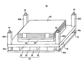
- FIG. 1 is a perspective view showing an embodiment of a plate-like body packing unit constituting a plate-like body packing structure according to the present invention.
- FIG. 2 is an enlarged view showing the strut engaging structure of the plate-like body packing unit.
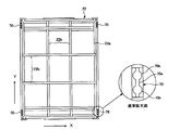
- FIG. 3 is a bottom view and an enlarged bottom view showing the configuration of the pedestal of the plate-like body packing unit.
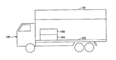
- FIG. 4A is a side view for explaining an operation of loading the packaging unit laminate in the cargo compartment of the truck.
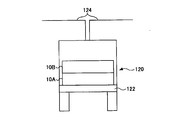
- FIG. 4B is a rear view for explaining the operation of loading the packaging unit stack in the cargo compartment of the truck.
- FIG. 4C is a side view for explaining the packaging unit laminate in a state where the packaging units are stacked in three stages.
- FIG. 4D is a rear view for explaining the packaging unit laminate in a state where the packaging units are stacked in three stages.
- FIG. 4E is a perspective view for explaining an operation of fixing the packing unit laminated body to the cargo compartment of the truck.
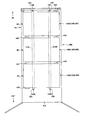
- FIG. 5 is a perspective view showing a packing unit stack for container loading having beams.
- FIG. 6 is a perspective view showing a packaging unit stack for container loading having a ceiling plate.
- FIG. 7 is a perspective view showing a packing unit stack for container loading having side walls.
- FIG. 8A is a side cross-sectional view for explaining a transport method for transporting the packaging unit laminate into the container.
- FIG. 8B is a side sectional view for explaining a state in which the packing units are stacked in three stages in the container.
- FIG. 8A is a side cross-sectional view for explaining a transport method for transporting the packaging unit laminate into the container.
- FIG. 8B is a side sectional view for explaining a state in which the packing units are
- FIG. 8C is a side cross-sectional view showing a state in which each stacked unit stacked body carried into the container is fixed by a lashing belt.
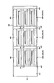
- FIG. 8D is a plan view showing a state in which each stacked unit stacked body carried into the container is fixed by a lashing belt.
- FIG. 9A is a side sectional view for explaining a modified example of the conveying method of the packing structure of the plate-like body.
- FIG. 9B is a side sectional view for explaining a state in which the packing units are stacked in three stages in the container.
- FIG. 9C is a side cross-sectional view showing a state in which a lashing belt is passed through each of the packing unit stacks carried into the container.
- FIG. 9A is a side sectional view for explaining a modified example of the conveying method of the packing structure of the plate-like body.
- FIG. 9B is a side sectional view for explaining a state in which the packing units are stacked in three stages in the container.
- FIG. 9D is a plan view showing a state in which a lashing belt is passed through each of the packaging unit stacks carried into the container.
- FIG. 9E is a side cross-sectional view showing a state in which each stacked unit stacked body carried into the container is fixed by a lashing belt.
- FIG. 10 is a side cross-sectional view showing a state in which an impact absorbing member is disposed between the ceiling of the container and each packing unit laminate.
- FIG. 1 is a perspective view showing an embodiment of a plate-like body packing unit constituting a plate-like body packing structure according to the present invention.
- the plate-shaped body packing unit 10 (hereinafter referred to as “packing unit”) includes a pedestal 20, a plate-shaped body mounting portion 30, and four columns 40A to 40D.
- the pedestal 20 is configured by combining the upper material 22, the lower material 24, and the space forming member 26.
- the space forming member 26 is a spacer for forming a space 28 into which a forklift claw (fork) is inserted between the upper material 22 and the lower material 24.
- the pedestal 20 is rectangular when viewed from above.
- struts 40A to 40D when attaching the struts 40A to 40D to the upper material 22, it may be configured to be inserted into a rectangular hole or a rectangular recess formed on the upper surface of the upper material 22.
- a plate-like body placing portion 30 is placed on the upper surface of the upper covering material 22.
- a vibration absorbing member 50 made of an elastic polymer such as silicon resin may be provided between the upper covering material 22 and the plate-like body mounting portion 30.
- Each support column 40A to 40D stands at the four corners of the upper surface of the upper material 22. Further, below each of the columns 40A to 40D, columns 40a to 40d extending so as to connect the upper material 22 and the lower material 24 are erected.
- a plate-like body 60 made of a glass substrate formed in a plate shape is placed on the plate-like body placing portion 30.
- the plate-like body 60 is laminated in advance via a buffer member made of paper or a resin film, and is packed as a laminate of plate-like bodies.
- a stopper member for preventing displacement may be appropriately disposed on the side surface of each plate-like body 60.
- FIG. 2 is an enlarged view showing the strut engagement structure of the packing unit.
- each of the support posts 40A to 40D has an engaging projection 42 protruding at the upper end.
- an engagement recess 44 with which the engagement projection 42 is engaged is provided at the lower end of each of the columns 40a to 40d.
- a lower part is a rectangular parallelepiped and the upper part is a quadrangular pyramid shape.
- the engaging recess 44 has a concave shape slightly larger than the outer dimension of the engaging protrusion 42 so that the engaging protrusion 42 can be engaged.
- the shape of each of the columns 40A to 40D, the engaging convex portion 42, and the engaging concave portion 44 is not limited to the above-described shape.
- the engaging recess 44 that opens on the bottom side of each column 40A to 40D of the upper packaging unit 10B is provided with the lower packaging unit 10A. Alignment is performed so as to face the engaging projections 42 projecting from the upper ends of the columns 40A to 40D. Then, by lowering the packing unit 10B, the engaging protrusions 42 provided at the upper ends of the respective columns 40A to 40D of the packing unit 10A and the engagements provided at the lower ends of the respective columns 40a to 40d of the packing unit 10B. The recessed portion 44 is engaged, and the upper packaging unit 10B can be prevented from falling off even when a horizontal force is applied during conveyance.
- FIG. 3 is a bottom view showing the configuration of the base 20 of the plate-like packaging unit.
- a pair of hooking portions 70 are provided at a total of four locations on the lower surfaces of the left and right edge portions of the upper material 22 of the base 20.
- the latching portion 70 is a combination of a linear latching groove 70a called an airline rail logistic track for latching a lashing belt and a plurality of circular grooves 70b.
- a hooked portion having a flange at the tip of the shape is configured to be inserted and locked by sliding from the side.
- the latching portion 70 is attached so that the latching groove 70a and the circular groove 70b face downward, and as will be described later, the first end of the lashing belt is lowered when loaded in the cargo space of the truck. Concatenated from At this time, it is preferable that the above-described latching portion 70 is also provided on the bottom surface of the cargo compartment of the truck.
- the upper member 22 of the pedestal 20 is formed of metal so as not to be deformed by the load of the loaded plate-like body 60, and a plurality of frames 22b are X, It is laid horizontally in a grid in the Y direction.
- FIG. 4A is a side view for explaining an operation of loading a packing unit stacked body in which a plurality of the packing units are stacked in a cargo room of a truck.
- FIG. 4B is a rear view for explaining the operation of loading the packing unit laminate in the cargo compartment of the truck.
- the truck 120 has an openable / closable luggage compartment wall portion 124 in the luggage compartment 122.
- the loading chamber wall 124 rotates upward to open the left and right sides of the loading chamber 122.
- each packing unit 10 has a mass of 1.5 to 1.6 t. Therefore, for example, when a plurality of packing units 10 are stacked to approach the limit of the forklift conveyance capacity, or when the center of gravity of the stacked packing units 10 becomes high, the balance of the lifting operation by the forklift at the time of loading may not be stable. is there.
- the forklift operator lifts up the transportable two-tiered packing units 10A and 10B and loads them on the front side of the cargo compartment 122 of the truck 120.
- FIG. 4C is a side view for explaining a state in which the packing units are stacked in three stages.
- FIG. 4D is a rear view for explaining a state in which the packing units are stacked in three stages.
- the forklift operator stacks the packing units 10C on the packing units 10A and 10B and stacks them in three stages in the second loading operation.
- the packaging unit stack 90 in which the packaging units 10A to 10C are stacked in three stages is stacked in the luggage compartment of the truck 120.
- the width dimensions of the packing units 10A to 10C are only slightly smaller than the width dimension of the cargo compartment 122, and the gap with the cargo compartment wall 124 is about 15 mm. However, since the cargo compartment wall 124 is open upward, the truck 120 can perform a fixing operation of restraining the packaging unit stack 90 to the cargo compartment 122 by a lashing belt on both the left and right sides.
- FIG. 4E is a perspective view for explaining the operation of fixing the packaging unit laminate to the cargo compartment of the truck.
- the packing unit laminate 90 in the plate-like packing structure 100 includes an engaging protrusion 42 formed at the upper end of each column 40A to 40D of each packing unit 10A to 10C, and each column.
- the engagement recesses 44 formed at the lower ends of 40a to 40d are engaged with each other to be overlapped in three stages.
- the packing unit laminate 90 is in a state where the support columns 40A to 40D of the packing units 10A to 10C are engaged with the engaging convex portions 42 and the engaging concave portions 44 (see FIG. 2). Even when a force in the horizontal direction is applied, it is possible to prevent the packing units 10A to 10C from shifting in the horizontal direction and maintain a structure that does not cause load collapse.
- the packaging units 10A to 10C are restrained in the luggage compartment 122 via a plurality of lashing belts 110 coupled to the uppermost packaging unit 10C.
- 4E shows a state in which a pair of lashing belts 110 are connected to the R direction side of the packaging unit laminate 90.
- FIG. Although the side surface in the L direction of the packaging unit laminate 90 is hidden and cannot be seen, a pair of lashing belts 110 are connected in the same manner as the side surface in the R direction.
- Each lashing belt 110 is provided with a collar portion (not visible in FIG. 4E) that is hooked to a hooking portion 70 provided on the lower surface of the upper material 22 of the base 20 at the first end (upper end). At the two ends (lower ends), a hook portion 112 that is hooked by a hooking portion 126 fixed on the cargo compartment 122 is provided. Note that the upper and lower flanges 112 of each lashing belt 110 have hooks that are inserted into the latching grooves 70 a of the latching part 70 and latched.
- latching portion 126 is exposed such that the latching groove 128 to which the flange portion 112 of each lashing belt 110 is engaged and the upper surface of the latching portion 126 is the same height as the floor surface of the luggage compartment 122. It is attached.
- each lashing belt 110 has a shape that can be easily hooked by a hook 126 fixed to the cargo compartment 122.
- the latching portion 70 has an airline rail type structure, but the latching portion 126 fixed to the luggage compartment 122 is also preferably an airline rail type structure, because space can be saved. As described above, since the gap between the packing unit and the openable / closable door of the truck is about 15 mm, it is difficult or impossible to insert a hook-type hook into the gap. By using the latching portion 126 of the structure, the problem of space limitation can be solved.
- the uppermost packing unit 10C of the packing unit stack 90 is attached to the lashing belts 110 that are hooked on the hooks 70.
- the packing unit stack 90 is fixed so as not to move up and down due to vibration during transportation.
- each lashing belt 110 is adjusted so as not to sag with a predetermined tension or more, so that the packing unit laminate 90 can be restrained to a stable state without rattling.
- the packing units 10A to 10C are not separated even when vertical vibration occurs, and the collapse of the load can be prevented.
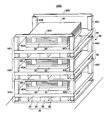
- FIG. 5 is a perspective view showing a packing unit stack 90 for loading in a container, and is provided with a belt hanging member formed of a beam in the uppermost packing unit 10C.
- the same parts as those of the packaging unit stack for loading on the truck are denoted by the same reference numerals, and the description thereof is omitted.
- the first beam 80A horizontally mounted between the upper ends of two adjacent columns 40A, 40D
- the two And the second beam 80B horizontally mounted between the upper ends of the other two columns 40B and 40C facing the columns 40A and 40D.
- the beams 80A and 80B are made of wood, metal rod, resin rod or the like formed in a rod shape, and between the upper ends of adjacent columns (between 40A and 40D and between 40B and 40C) among the columns 40A to 40D. Between each other, and they are arranged in parallel in the same direction. Further, at the bottoms of both ends of each beam 80A and 80B, recesses (not shown) having a shape that engages with the engagement protrusions 42 at the upper ends of the columns 40A to 40D are formed.
- the packing unit laminate 90 having a pair of parallel beams 80A and 80B at the top, the beams 80A and 80B function as belt hanging members when the lashing belt is hung, and the lashing belt Contact with the plate-like body 60 can be prevented.
- the beams 80A and 80B are engaged with the engaging projections 42 projecting from the upper ends of the columns 40A to 40D.
- a polypropylene band PP
- the base 20 may be bound to a proper position by a resin belt called a band.
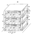
- FIG. 6 is a perspective view showing a packing unit stack 90 for loading in a container, and is provided with a belt hanging member formed of a ceiling plate in the uppermost packing unit 10C.
- the same parts as those of the packaging unit stack for loading on the truck are denoted by the same reference numerals, and the description thereof is omitted.
- the ceiling plate 210 is supported between the upper ends of the columns 40A to 40D.
- the ceiling plate 210 is formed in a dimension having a plane having the same size as the upper surface of the pedestal 20, and is arranged so as to cover the entire upper surface of the plate-like body 60.
- the ceiling plate 210 is made of wood, a metal member, a resin material, or the like, and functions as a belt-hanging member that entirely covers the top of the uppermost packaging unit 10C. In the four corners on the lower surface side of the ceiling plate 210, it is preferable that recesses (not shown) that are engaged with the engagement protrusions 42 at the upper ends of the columns 40A to 40D are formed. In addition, the ceiling board 210 should just be supported by the upper end of at least three support
- the ceiling plate 210 functions as a belt hanging member when the lashing belt is hung, and the lashing belt contacts the plate-like body 60. Can be prevented.
- FIG. 7 is a perspective view showing a packaging unit laminate 90 for loading on a container, and includes a belt-hanging member composed of side walls.
- the same parts as those of the packaging unit stack for loading on the truck are denoted by the same reference numerals, and the description thereof is omitted.
- the first side wall 310A horizontally mounted between the side surfaces of two adjacent columns 40A, 40D
- the two And the second side wall 310B horizontally mounted between the side surfaces of the other two support columns 40B and 40C facing the support columns 40A and 40D.
- the side walls 310A and 310B are made of plate-shaped wood, metal plate, resin plate, or the like, and between the side surfaces of adjacent columns (between 40A and 40D and between 40B and 40C) among the columns 40A to 40D. Between each other, and each is arranged in parallel. A method for horizontally fixing the side walls 310A and 310B to the columns 40A to 40D is not particularly limited.
- the packaging unit laminate 90 having a pair of parallel side walls 310A and 310B at the top, the side walls 310A and 310B function as belt hanging members when the lashing belt is hung, and the lashing belt Contact with the plate-like body 60 can be prevented.
- FIG. 8A is a side cross-sectional view for explaining a method of loading the packaging unit laminate.
- the packaging unit laminate 90 in which the packaging units 10A to 10C are stacked in three stages cannot be lifted at a time depending on the capacity of the forklift. Therefore, in this embodiment, the packaging units 10A and 10B are first carried in, and then the packaging unit 10C is carried in, whereby the packaging units 10A to 10C are carried into the container 400.
- the container 400 is a box that is carried on a trailer (towed vehicle) or a cargo ship.
- the trailer is pulled by a tractor (traction vehicle).
- a tractor traction vehicle
- the total length is defined as 12.192 m
- the width is 2.438 m
- the height is defined as 2.591 m.
- the horizontal width dimension of the opening of the container 400 and the horizontal width dimension of the inner wall of the container 400 are smaller than the above numerical values, and are approximately 2.3 m.
- the left and right side surfaces of the packaging unit laminate 90 approach the left and right inner walls 404 of the container 400 with a slight gap (about 15 mm). Therefore, the operator cannot move to the inner part of the container 400 through the gap between the left and right side surfaces of the packaging unit laminate 90. Therefore, when carrying the packing unit stack 90 into the container 400, the lashing belt 410 must be hooked in the back of the container 400 in advance.
- the flange portion 420 at the first end of the lashing belt 410 is hooked on a hook-shaped hook portion 440 provided in advance on the floor 406 at the back of the container 400.
- a pair of lashing belts 410 is previously placed on the left and right inner walls 404 of the container 400 at a position higher than the packing unit laminate 90 from the back to the opening 402 side and along the upper portions of the left and right inner walls 404 before carrying in. It is temporarily fixed by an adhesive tape 405.
- the second end flange 450 on the opening 402 side of the lashing belt 410 is also temporarily fixed in the vicinity of the opening 402 by an adhesive tape 405.
- the lashing belt 410 does not interfere with the movement of the forklift.
- a stopper member 430 that contacts the carry-in side end (IN-side end) of the lowermost plate-like body packing unit 10A before carrying-in work in advance is provided at the back of the container 400. It is attached to the floor surface 406. Subsequently, in the first carry-in operation by the forklift, as described above, the two-tiered packing units 10A and 10B that are equal to or less than the maximum transfer mass of the forklift are carried into the back of the container 400 and installed on the floor surface 406.
- the stopper member 430 ′ that comes into contact with the unloading side end (OUT side end) of the lowermost packing unit 10A is placed on the container 400. It is attached to the floor surface 406 so that the packing unit 10A is not displaced in the front-rear direction during transportation.
- FIG. 8B is a side sectional view for explaining a state in which the packing units 10A to 10C are stacked in three stages in the container.
- the packaging unit laminate 90 in FIG. 8B is first loaded with the two-tiered packaging units 10A and 10B into the container 400 using a forklift, and then loaded with the packaging unit 10C using a forklift and stacked on the packaging unit 10B. Is.
- the packaging unit 10C at the third stage has an engaging recess 44 opened on the bottom surface side of each column 40A to 40D at the upper end of each column 40A to 40D of the lower plate-shaped packaging unit 10B. It is positioned by engaging with the projecting engaging protrusion 42 (see FIG. 2).
- the lashing belt 410 is temporarily fixed to the left and right inner walls 404 of the container 400 so as to be positioned above the uppermost packaging unit 10C.
- the carry-in operation of the packing units 10A to 10C divided into two times is performed a plurality of times as necessary.
- FIG. 8C is a side cross-sectional view showing a state in which each packing unit laminate 90 carried into the container is fixed by a lashing belt
- FIG. 8D is a drawing showing each packing unit laminate 90 carried in the container fixed by a lashing belt. It is a top view which shows the state which carried out.
- the operator can move the first lashing belt 410 positioned on the opening side (OUT side) of the container 400.
- the two end flanges 450 are pulled out, the lashing belt 410 is brought into contact with and passed above each packing unit laminate 90, and the second end of the lashing belt 410L extending from the back in the L direction in FIG.
- the hooking portion 440 ⁇ / b> R disposed on the R direction side is hooked, and the flange portion 450 at the second end of the R direction side lashing belt 410 ⁇ / b> R is hooked on the hooking portion 440 ⁇ / b> L on the L direction side of the floor surface 406.
- the pair of lashing belts 410 (410L, 410R) cross over the three packing unit stacks 90 to restrain the three sets of packing unit stacks 90.
- the flange 450 provided at the second end of the lashing belt 410 is in a state where the lashing belt 410 is placed on the front side (OUT side) of the packing unit laminate 90 from the top of the packaging unit laminate 90. It is latched by the latch part 440 (440L, 440R).
- the lashing belt 410 is wrapped around each packing unit stack 90 even though there is no gap for the operator to enter the container 400.
- each packing unit stack 90 can be constrained to the floor 406 of the container 400 so that it does not operate in the vertical direction.
- each packing unit laminate 90 includes beams 80A and 80B (see FIG. 5) and a ceiling plate 210 (see FIG. 6) at the upper ends of the columns 40A to 40D of the uppermost packing unit 10C. Or sidewalls 310A, 310B (see FIG. 7). Therefore, the lashing belt 410 is attached so as not to come into contact with the uppermost plate 60 by being wrapped around the beams 80A and 80B, the ceiling plate 210, or the side walls 310A and 310B.
- the length of the lashing belt is adjusted in the longitudinal direction so that the lashing belt 410 does not sag, and a predetermined tension is applied to the lashing belt 410.
- FIG. 9A is a side sectional view for explaining a modified example of the conveying method of the packing structure of the plate-like body.
- a stopper member 430 that comes into contact with the back end (IN side end) of the lowermost packaging unit 10A is placed on the floor 406 at the back of the container 400.
- the first loading operation (packing unit 10A, 10B loading and installation) is performed by a forklift, and the stopper member 430 ′ that contacts the front end (OUT side end) of the lowermost packing unit 10A is placed in the container.
- the lashing belt 410 is passed over the second-stage packing unit 10B.
- the IN side first flange portion 420 of the lashing belt 410 is hooked on a hook-shaped hook portion 440 provided in advance on the floor 406 at the back of the container 400.
- the forklift performs the second loading operation (carrying in and installing the packing unit 10C)
- the flange on the second end on the OUT side of the lashing belt 410 450 is passed through the space 28 formed in the base 20 of the packaging unit 10C.
- the forklift enters the inside of the container 400, and an operator pulls out the second end collar portion 450 of the lashing belt 410 toward the opening 402 side (OUT direction) of the container 400.
- the operator pulls the lashing belt 410 toward the opening 402 (OUT direction) so that the lashing belt 410 passes through the space 28 of the base 20 of the packaging unit 10C while the packaging unit 10C is lifted by a forklift.
- the forklift can move to the inner part of the container 400.
- the operation of pulling out the lashing belt 410 toward the opening 402 side (OUT direction) of the container 400 may be performed manually by an operator or may be pulled out by an electric winding device.
- FIG. 9B is a side sectional view for explaining a state in which the packing units 10A to 10C are stacked in three stages in the container.
- the uppermost packaging unit 10C is stacked on the two-tiered packaging units 10A and 10B carried into the container 400 for the first time.
- the third-stage (topmost) packing unit 10C has an engagement recess 44 that opens on the bottom surface side of each support column 40A to 40D and protrudes to the upper end of each support column 40A to 40D of the lower-stage packing unit 10B. It is positioned by engaging with the mating convex portion 42 (see FIG. 2).
- FIG. 9C is a side cross-sectional view showing a state in which the lashing belt 410 is passed through each packing unit laminate 90 carried into the container.
- the flange 450 at the second end of the lashing belt 410 is connected to each packing unit stack 90. It passes through the space 28 of each base 20 of the uppermost packaging unit 10 ⁇ / b> C and is drawn out to the opening 402 side of the container 400.
- FIG. 9D is a plan view showing a state in which a lashing belt is passed through each packing unit stacked body carried into the container.
- FIG. 9E is a side cross-sectional view showing a state in which each stacked unit stacked body carried into the container is fixed by a lashing belt.
- the flanges 450 provided at the second ends of the pair of lashing belts 410 (410L, 410R) are removed. Then, the container 400 is hooked on a hooking portion 440 (440L, 440R) provided on the floor surface 406 on the opening 402 side.
- the length of the lashing belt is adjusted in the longitudinal direction so that the lashing belt 410 does not sag, and a predetermined tension is applied to the lashing belt 410.
- the flange 450 at the second end of the lashing belt 410 (410L, 410R) is attached to each packaging unit laminate.
- the container 400 is pulled out to the opening 402 side (OUT direction) of the container 400 while being passed through the space 28 of the pedestal 20 of the uppermost packaging unit 10C. Therefore, the worker can connect both ends of the lashing belt 410 (410L, 410R) to the floor surface 406 without moving to the back (in the direction away from the opening 402) of each packing unit laminate 90 installed in the container 400.
- the packing unit stack 90 can be fixed so as to suppress vertical vibration by being hooked on the hooking portion 440.
- this invention does not prevent taking the method of carrying in the packing unit 10B and the packaging unit 10BC of 2 steps
- FIG. 10 is a side cross-sectional view showing a state in which the impact absorbing member 460 is disposed between the ceiling of the container 400 and each packing unit laminate 90.
- FIG. 10 when the fixing operation by the lashing belt 410 described above is not performed, after each packing unit stack 90 is installed on the floor 406 of the container 400, the upper part of the uppermost packing unit 10C and the container The shock absorbing member 460 is inserted between the 400 ceilings. In the present invention, the fixing operation by the lashing belt 410 and the combined use of the shock absorbing member 460 are not disturbed.
- the impact absorbing member 460 is formed of an air bag that is inflated by air pressure, and is in a thinly folded state during the insertion operation, so that it can be easily installed on the upper part of the packing unit laminate 90.
- the shock absorbing member 460 bulges by supplying compressed air, abuts against the ceiling of the container 400, and can fix the upper portion of each packing unit stack 90 by air pressure.
- a damper or the like that can suppress excessive expansion and contraction can be used as the impact absorbing member 460, but an airbag is preferable from the viewpoint of workability.
- each packing unit laminate 90 has beams 80A and 80B (see FIG. 5), a ceiling plate 210 (see FIG. 6), or an upper end of each column 40A to 40D of the uppermost packing unit 10C.
- Side walls 310A and 310B are provided.
- the shock absorbing member 460 is used, the upper surface side on which the shock absorbing member 460 contacts is used to prevent a load on a plate-like body made of glass or the like. It is preferable to use the ceiling plate 210 having a large contact area. The shock absorbing member 460 is attached so as not to contact the uppermost plate-like body 60 by contacting the ceiling plate 210.
- each impact absorbing member 460 absorbs vibrations by air pressure, and the collapse of each packing unit laminate 90 can be prevented.
- the beam 80 and the side wall 310 are replaced with the ceiling plate 210. There is no problem even if it is provided.
- the shock absorbing member 460 can be easily removed by removing the compressed air from the shock absorbing member 460.
- the glass substrate is described as an example of the plate-like body.
- the present invention is not limited to this, and a plate-like body other than the glass substrate (of a material that is easily damaged by an impact during transportation) is packed.
- the present invention can also be applied to the case of conveyance.
- the latching portion 126 of the cargo compartment 122 of the truck 120 has an airline rail type structure, and the latching portion 440 provided on the floor 406 of the container 400 has been described as a saddle type.
- the present invention is not limited to this, and other structures and other shapes may be used as long as the end of the lashing belt is hooked.
- Plate body packing unit 20 Base 22 Upper material 24 Lower material 26 Space forming member 28 Space 30 Plate body mounting portions 40A to 40D Posts 40a to 40d Posts 42 Engaging projections 44 Engaging recesses 50 Vibration absorbing member 60 Plate-like body 70, 126 Hook part 70a, 128 Hatch groove 70b Circular groove 22a Frame body 22b Frame 80A First beam 80B Second beam 90 Packing unit laminate 100, 100A, 200, 300 Plate Packing structure 112-like part 120 Truck 122 Cargo compartment 124 Cargo compartment wall part 110, 410 (410L, 410R) Lashing belt 210 Ceiling plate 310A First side wall 310B Second side wall 400 Container 402 Opening 404 Inner wall 405 Adhesive tape 406 Floor surface 420 ridge part 430, 430 'stopper member 440 (440L, 440R) Stop portion 450 hook 460 shock absorbing member
Landscapes
- Engineering & Computer Science (AREA)
- Mechanical Engineering (AREA)
- Pallets (AREA)
- Packaging Frangible Articles (AREA)
- Packaging Of Annular Or Rod-Shaped Articles, Wearing Apparel, Cassettes, Or The Like (AREA)
- Package Frames And Binding Bands (AREA)
- Stackable Containers (AREA)
- Packaging Of Machine Parts And Wound Products (AREA)
- Packages (AREA)
Abstract
Description
(1)本発明は、上張り材および下張り材ならびにこれらの間に空間を形成する空間形成部材を有する台座と、該台座に載置される板状体載置部と、前記台座の四隅に起立し、上端に係合部を有する支柱とを有する板状体梱包ユニットが、
前記支柱の下端が別の前記板状体梱包ユニットの前記支柱の上端に係合するように複数積み重ねられ、梱包ユニット積層体を形成している。
(2)本発明において、最上段の板状体梱包ユニットの支柱間に、前記梱包ユニット積層体の上下方向の動きを拘束するラッシングベルトを掛ける際に当該ラッシングベルトが接するベルト掛け部材を設けた。
(3)本発明において、前記ベルト掛け部材は、最上段の板状体梱包ユニットの、隣接する2本の前記支柱の上端間に横架された第1の梁と、
最上段の板状体梱包ユニットの、前記2本の支柱に対向する他の2本の支柱の上端間に横架された第2の梁とからなる。
(4)本発明において、前記ベルト掛け部材は、最上段の板状体梱包ユニットの、少なくとも3本の前記支柱の上端に支持される天井板からなる。
(5)本発明において、前記ベルト掛け部材は、最上段の板状体梱包ユニットの、隣接する2本の前記支柱の側面間に横架された第1の側壁と、
最上段の板状体梱包ユニットの、前記2本の支柱に対向する他の2本の支柱の側面間に横架された第2の側壁とからなる。
(6)本発明において、前記板状体載置部は、複数の板状体を積層した状態で保持する。
(7)本発明において、前記上張り材の下面には、鉤部が掛止される掛止部を備える。
(8)本発明は、ラッシングベルトの第1端を掛止させる掛止部を有する板状体梱包ユニットを複数積み重ね、(1)乃至(7)の何れか1項に記載の梱包ユニット積層体を形成し、前記梱包ユニット積層体を前記ラッシングベルトによってトラックに固定して搬送する板状体搬送方法であって、前記梱包ユニット積層体をトラックの荷室に載置した後、前記最上段の板状体梱包ユニットの前記掛止部にラッシングベルトの第1端を掛止させ、当該ラッシングベルトの第2端を前記トラックの荷室の掛止部に掛止させて前記梱包ユニット積層体を前記トラックに固定して搬送する。
(9)本発明において、板状体梱包ユニットを複数積み重ね、(1)乃至(7)の何れか1項に記載の梱包ユニット積層体を形成し、前記梱包ユニット積層体を前記ラッシングベルトによってコンテナに固定して搬送する板状体搬送方法であって、前記梱包ユニット積層体をコンテナに収納した後、前記梱包ユニット積層体にラッシングベルトを巻き掛けして前記梱包ユニット積層体を前記コンテナに固定して搬送する。
(10)本発明において、(9)に記載の板状体搬送方法であって、前記梱包ユニット積層体を固定するラッシングベルトの両端に鉤部を設け、
前記コンテナの床面に前記鉤部を掛止する掛止部を設け、
前記鉤部は、前記ラッシングベルトを前記梱包ユニット積層体の上から前記梱包ユニット積層体の側面に這わした状態で前記掛止部に掛止される。
(11)本発明において、(9)又は(10)に記載の板状体搬送方法であって、
前記コンテナの内壁の奥部に前記梱包ユニット積層体を拘束するラッシングベルトの第1端を掛止すると共に、当該ラッシングベルトを前記コンテナの内壁に沿うように這わせて仮止めし、前記梱包ユニット積層体を前記コンテナの開口側より前記コンテナの内部に搬入し、その後、仮止めされた前記ラッシングベルトの他端を前記コンテナの開口側に引き出して前記梱包ユニット積層体の上面及び側面に前記ラッシングベルトを接した状態で前記コンテナの床面に掛止させる。
(12)本発明において、(9)に記載の板状体搬送方法であって、
前記コンテナの内壁の奥部に前記梱包ユニット積層体を拘束するラッシングベルトの第1端を掛止し、前記梱包ユニット積層体のうちの最上段の板状体梱包ユニットの台座に形成された空間に前記ラッシングベルトの第2端を通過させ、
前記梱包ユニット積層体を前記コンテナの開口側より前記コンテナの内部に搬入すると共に、前記ラッシングベルトの第2端を前記コンテナの開口側に引き出し、前記最上段の板状体梱包ユニットの台座を前記ラッシングベルトにより前記コンテナの床面に固定する。
(13)本発明において、板状体梱包ユニットを複数積み重ね、(1)乃至(7)の何れか1項に記載の梱包ユニット積層体を形成し、前記梱包ユニット積層体をコンテナに収納することを含む、板状体搬送方法であって、
前記梱包ユニット積層体と前記コンテナの天井との間に衝撃吸収部材が挿入されている。
(14)本発明において、前記衝撃吸収部材は、空気圧によって膨らませたエアバッグである。
図1は、本発明による板状体の梱包構造を構成する板状体梱包ユニットの一実施例を示す斜視図である。図1に示されるように、板状体梱包ユニット10(以下、「梱包ユニット」と称する)は、台座20と、板状体載置部30と、4本の支柱40A~40Dを有する。台座20は、上張り材22と、下張り材24と、空間形成部材26とを組み合わせた構成である。空間形成部材26は、上張り材22と下張り材24との間にフォークリフトのツメ(フォーク)が挿入される空間28を形成するためのスペーサである。前記台座20は、上方から見ると矩形である。
図4Aは、前記梱包ユニットを複数積み重ねた梱包ユニット積層体をトラックの荷室に積載する作業を説明するための側面図である。図4Bは前記梱包ユニット積層体をトラックの荷室に積載する作業を説明するための背面図である。
前述のように、側壁が開閉可能なトラックの荷室への積載の場合は、上張り材22の下面に設けられた掛止部70を使って梱包ユニット積層体90を安定させることが可能であるが、開閉可能な側壁を持たないコンテナに梱包ユニット積層体90を積載する場合、前記掛止部70を利用することができない。そのため、本発明者は、ラッシングベルトが接するベルト掛け部材を設けることにより、前記ラッシングベルトのガラスへの接触を防止して輸送時の安定化を図る方法を見出した。以下、ベルト掛け部材を有する梱包ユニット積層体の3つの形態を説明する。
まず、ベルト掛け部材として梁を用いる第1の形態を説明する。図5は、コンテナに積載するための梱包ユニット積層体90を示す斜視図であり、最上段の梱包ユニット10Cに梁で構成されるベルト掛け部材を備えたものである。尚、図5において、トラックに積載するための梱包ユニット積層体と同一部分には、同一符合を付してその説明を省略する。
次いで、ベルト掛け部材として天井板を用いる第2の形態を説明する。図6は、コンテナに積載するための梱包ユニット積層体90を示す斜視図であり、最上段の梱包ユニット10Cに天井板で構成されるベルト掛け部材を備えたものである。尚、図6において、トラックに積載するための梱包ユニット積層体と同一部分には、同一符合を付してその説明を省略する。
さらに、ベルト掛け部材として一対の側壁を用いる第3の形態を説明する。図7は、コンテナに積載するための梱包ユニット積層体90を示す斜視図であり、側壁で構成されるベルト掛け部材を備えたものである。尚、図7において、トラックに積載するための梱包ユニット積層体と同一部分には、同一符合を付してその説明を省略する。
次に、上記各板状体の梱包構造100A、200、300により梱包された梱包ユニット積層体90をコンテナに積載して搬送する方法について説明する。
次にラッシング方法の変形例について説明する。
図10は、コンテナ400の天井と各梱包ユニット積層体90との間に衝撃吸収部材460を配した状態を示す側断面図である。図10に示されるように、前述したラッシングベルト410による固定作業を行なわない場合は、各梱包ユニット積層体90をコンテナ400の床面406に設置した後、最上段の梱包ユニット10Cの上部とコンテナ400の天井との間に衝撃吸収部材460を挿入する。なお、本発明においては、ラッシングベルト410による固定作業と衝撃吸収部材460の併用を妨げるものではない。
本出願は、2010年7月6日出願の日本特許出願2010-154072に基づくものであり、その内容はここに参照として取り込まれる。
20 台座
22 上張り材
24 下張り材
26 空間形成部材
28 空間
30 板状体載置部
40A~40D 支柱
40a~40d 支柱
42 係合凸部
44 係合凹部
50 振動吸収部材
60 板状体
70、126 掛止部
70a、128 掛止溝
70b 円形溝
22a 枠体
22b フレーム
80A 第1の梁
80B 第2の梁
90 梱包ユニット積層体
100、100A、200、300 板状体の梱包構造
112 鉤部
120 トラック
122 荷室
124 荷室壁部
110、410(410L,410R) ラッシングベルト
210 天井板
310A 第1の側壁
310B 第2の側壁
400 コンテナ
402 開口
404 内壁
405 粘着テープ
406 床面
420 鉤部
430、430’ ストッパ部材
440(440L,440R) 掛止部
450 鉤部
460 衝撃吸収部材
Claims (14)
- 上張り材および下張り材ならびにこれらの間に空間を形成する空間形成部材を有する台座と、該台座に載置される板状体載置部と、前記台座の四隅に起立し、上端に係合部を有する支柱とを有する板状体梱包ユニットが、
前記支柱の下端が別の前記板状体梱包ユニットの前記支柱の上端に係合するように複数積み重ねられ、梱包ユニット積層体を形成している板状体の梱包構造。 - 最上段の板状体梱包ユニットの支柱間に、前記梱包ユニット積層体の上下方向の動きを拘束するラッシングベルトを掛ける際に当該ラッシングベルトが接するベルト掛け部材を設けた請求項1に記載の板状体の梱包構造。
- 前記ベルト掛け部材は、
最上段の板状体梱包ユニットの、隣接する2本の前記支柱の上端間に横架された第1の梁と、
最上段の板状体梱包ユニットの、前記2本の支柱に対向する他の2本の支柱の上端間に横架された第2の梁とからなる請求項2に記載の板状体の梱包構造。 - 前記ベルト掛け部材は、
最上段の板状体梱包ユニットの、少なくとも3本の前記支柱の上端に支持される天井板からなる請求項2に記載の板状体の梱包構造。 - 前記ベルト掛け部材は、
最上段の板状体梱包ユニットの、隣接する2本の前記支柱の側面間に横架された第1の側壁と、
最上段の板状体梱包ユニットの、前記2本の支柱に対向する他の2本の支柱の側面間に横架された第2の側壁とからなる請求項2に記載の板状体の梱包構造。 - 前記板状体載置部は、複数の板状体を積層した状態で保持する請求項1乃至5の何れか1項に記載の板状体の梱包構造。
- 前記上張り材の下面に、鉤部が掛止される掛止部を備える請求項1乃至6の何れか1項に記載の板状体の梱包構造。
- ラッシングベルトの第1端を掛止させる掛止部を有する板状体梱包ユニットを複数積み重ね、請求項1乃至7の何れか1項に記載の梱包ユニット積層体を形成し、前記梱包ユニット積層体を前記ラッシングベルトによってトラックに固定して搬送する板状体搬送方法であって、
前記梱包ユニット積層体をトラックの荷室に載置した後、前記最上段の板状体梱包ユニットの前記掛止部にラッシングベルトの第1端を掛止させ、当該ラッシングベルトの第2端を前記トラックの荷室の掛止部に掛止させて前記梱包ユニット積層体を前記トラックに固定して搬送する板状体搬送方法。 - 板状体梱包ユニットを複数積み重ね、請求項1乃至7の何れか1項に記載の梱包ユニット積層体を形成し、前記梱包ユニット積層体を前記ラッシングベルトによってコンテナに固定して搬送する板状体搬送方法であって、
前記梱包ユニット積層体をコンテナに収納した後、前記梱包ユニット積層体に前記ラッシングベルトを巻き掛けして前記梱包ユニット積層体を前記コンテナに固定して搬送する板状体搬送方法。 - 請求項9に記載の板状体搬送方法であって、
前記梱包ユニット積層体を固定するラッシングベルトの両端に鉤部を設け、
前記コンテナの床面に前記鉤部を掛止する掛止部を設け、
前記鉤部は、前記ラッシングベルトを前記梱包ユニット積層体の上から前記梱包ユニット積層体の側面に這わした状態で前記掛止部に掛止される板状体搬送方法。 - 請求項9又は10に記載の板状体搬送方法であって、
前記コンテナの内壁の奥部に前記梱包ユニット積層体を拘束するラッシングベルトの第1端を掛止すると共に、当該ラッシングベルトを前記コンテナの内壁に沿うように這わせて仮止めし、前記梱包ユニット積層体を前記コンテナの開口側より前記コンテナの内部に搬入し、その後、仮止めされた前記ラッシングベルトの第2端を前記コンテナの開口側に引き出して、前記梱包ユニット積層体の上面及び側面に前記ラッシングベルトを接した状態で、前記コンテナの床面に掛止させる板状体搬送方法。 - 請求項9に記載の板状体搬送方法であって、
前記コンテナの内壁の奥部に前記梱包ユニット積層体を拘束するラッシングベルトの第1端を掛止し、前記梱包ユニット積層体のうちの最上段の板状体梱包ユニットの台座に形成された空間に前記ラッシングベルトの第2端を通過させ、
前記梱包ユニット積層体を前記コンテナの開口側より前記コンテナの内部に搬入すると共に、前記ラッシングベルトの第2端を前記コンテナの開口側に引き出し、前記最上段の板状体梱包ユニットの台座を前記ラッシングベルトにより前記コンテナの床面に固定する板状体搬送方法。 - 板状体梱包ユニットを複数積み重ね、請求項1乃至7の何れか1項に記載の梱包ユニット積層体を形成し、前記梱包ユニット積層体をコンテナに収納することを含む、板状体搬送方法であって、
前記梱包ユニット積層体と前記コンテナの天井との間に衝撃吸収部材が挿入されている板状体搬送方法。 - 前記衝撃吸収部材は、空気圧によって膨らませたエアバッグである請求項13に記載の板状体搬送方法。
Priority Applications (3)
| Application Number | Priority Date | Filing Date | Title |
|---|---|---|---|
| CN2011800335118A CN102985328A (zh) | 2010-07-06 | 2011-06-20 | 板状体的包装结构及板状体搬运方法 |
| JP2012523808A JPWO2012005105A1 (ja) | 2010-07-06 | 2011-06-20 | 板状体の梱包構造及び板状体搬送方法 |
| KR1020137000209A KR20130088823A (ko) | 2010-07-06 | 2011-06-20 | 판 형상체의 포장 구조 및 판 형상체 반송 방법 |
Applications Claiming Priority (2)
| Application Number | Priority Date | Filing Date | Title |
|---|---|---|---|
| JP2010-154072 | 2010-07-06 | ||
| JP2010154072 | 2010-07-06 |
Publications (1)
| Publication Number | Publication Date |
|---|---|
| WO2012005105A1 true WO2012005105A1 (ja) | 2012-01-12 |
Family
ID=45441091
Family Applications (1)
| Application Number | Title | Priority Date | Filing Date |
|---|---|---|---|
| PCT/JP2011/064087 Ceased WO2012005105A1 (ja) | 2010-07-06 | 2011-06-20 | 板状体の梱包構造及び板状体搬送方法 |
Country Status (5)
| Country | Link |
|---|---|
| JP (2) | JPWO2012005105A1 (ja) |
| KR (1) | KR20130088823A (ja) |
| CN (1) | CN102985328A (ja) |
| TW (1) | TW201206774A (ja) |
| WO (1) | WO2012005105A1 (ja) |
Cited By (1)
| Publication number | Priority date | Publication date | Assignee | Title |
|---|---|---|---|---|
| WO2022035668A1 (en) * | 2020-08-12 | 2022-02-17 | Corning Incorporated | Transporting method of glass substrates |
Families Citing this family (6)
| Publication number | Priority date | Publication date | Assignee | Title |
|---|---|---|---|---|
| CN104869782B (zh) * | 2015-04-03 | 2017-12-19 | 北京航天自动控制研究所 | 一种用于小型导弹控制设备的电子器件层式架构 |
| CN105501734A (zh) * | 2015-12-09 | 2016-04-20 | 浪潮电子信息产业股份有限公司 | 一种Rack的运输方法 |
| CN105480376B (zh) * | 2015-12-11 | 2017-09-22 | 浙江欧华造船股份有限公司 | 带有货物固定气囊的甲板 |
| ES2871748T3 (es) * | 2016-05-16 | 2021-11-02 | Jee Keng Lim | Palé modular y estructura de soporte multicapa |
| CN107804588B (zh) * | 2017-10-10 | 2019-04-05 | 安徽鑫迪发艺品有限公司 | 一种发艺品存储装置 |
| CN115362107B (zh) | 2020-04-21 | 2026-05-05 | 日本电气硝子株式会社 | 玻璃板输送单元 |
Citations (7)
| Publication number | Priority date | Publication date | Assignee | Title |
|---|---|---|---|---|
| JPS57177940U (ja) * | 1981-05-06 | 1982-11-11 | ||
| JPH0540180U (ja) * | 1991-10-28 | 1993-05-28 | 積水化成品工業株式会社 | 保冷容器 |
| WO2005113375A1 (ja) * | 2004-05-21 | 2005-12-01 | Dai Nippon Printing Co., Ltd | 基板収納容器、基板収納体及び基板輸送装置 |
| JP2007039110A (ja) * | 2005-08-04 | 2007-02-15 | Kyokuhei Glass Kako Kk | ガラス搬送パレット |
| JP2007112464A (ja) * | 2005-10-19 | 2007-05-10 | Dainippon Printing Co Ltd | 基板収納体 |
| WO2008105190A1 (ja) * | 2007-02-26 | 2008-09-04 | Asahi Glass Company, Limited | 板状体の梱包パレット |
| WO2009084605A1 (ja) * | 2007-12-28 | 2009-07-09 | Asahi Glass Co., Ltd. | 板状体収納容器 |
Family Cites Families (12)
| Publication number | Priority date | Publication date | Assignee | Title |
|---|---|---|---|---|
| JPS62116389A (ja) * | 1985-11-15 | 1987-05-27 | Mitsui Eng & Shipbuild Co Ltd | ラツシングベルト |
| JPS6299524U (ja) * | 1985-12-11 | 1987-06-25 | ||
| JPH0635794Y2 (ja) * | 1988-01-29 | 1994-09-21 | いすゞ自動車株式会社 | トラックの荷物固定装置 |
| JPH0565160A (ja) * | 1991-03-25 | 1993-03-19 | Tokyo Electric Co Ltd | 外装用具 |
| JP2573158Y2 (ja) * | 1992-10-28 | 1998-05-28 | 株式会社北村製作所 | 荷崩れ防止装置 |
| JPH074339U (ja) * | 1993-06-21 | 1995-01-24 | 積水化学工業株式会社 | ラックパレット |
| JPH09301422A (ja) * | 1996-05-14 | 1997-11-25 | Nissei Kk | 作業ベルト用バックル |
| JP3832085B2 (ja) * | 1998-03-30 | 2006-10-11 | 日本ゼオン株式会社 | 分解可能木製コンテナ |
| JP4667855B2 (ja) * | 2004-12-27 | 2011-04-13 | 有限会社 キュービック静岡 | 積載棚のパレットの横ずれ防止装置 |
| JP4852889B2 (ja) * | 2005-05-27 | 2012-01-11 | 大日本印刷株式会社 | 基板収納容器及び基板収納体 |
| JP4924982B2 (ja) * | 2006-12-07 | 2012-04-25 | 日本電気硝子株式会社 | ガラス板梱包方法及びガラス板梱包体 |
| JP5134910B2 (ja) * | 2007-10-25 | 2013-01-30 | 京セラドキュメントソリューションズ株式会社 | 輸送用ラック |
-
2011
- 2011-06-20 CN CN2011800335118A patent/CN102985328A/zh active Pending
- 2011-06-20 JP JP2012523808A patent/JPWO2012005105A1/ja not_active Withdrawn
- 2011-06-20 KR KR1020137000209A patent/KR20130088823A/ko not_active Withdrawn
- 2011-06-20 WO PCT/JP2011/064087 patent/WO2012005105A1/ja not_active Ceased
- 2011-07-01 TW TW100123373A patent/TW201206774A/zh unknown
-
2014
- 2014-01-14 JP JP2014004409A patent/JP5696795B2/ja not_active Expired - Fee Related
Patent Citations (7)
| Publication number | Priority date | Publication date | Assignee | Title |
|---|---|---|---|---|
| JPS57177940U (ja) * | 1981-05-06 | 1982-11-11 | ||
| JPH0540180U (ja) * | 1991-10-28 | 1993-05-28 | 積水化成品工業株式会社 | 保冷容器 |
| WO2005113375A1 (ja) * | 2004-05-21 | 2005-12-01 | Dai Nippon Printing Co., Ltd | 基板収納容器、基板収納体及び基板輸送装置 |
| JP2007039110A (ja) * | 2005-08-04 | 2007-02-15 | Kyokuhei Glass Kako Kk | ガラス搬送パレット |
| JP2007112464A (ja) * | 2005-10-19 | 2007-05-10 | Dainippon Printing Co Ltd | 基板収納体 |
| WO2008105190A1 (ja) * | 2007-02-26 | 2008-09-04 | Asahi Glass Company, Limited | 板状体の梱包パレット |
| WO2009084605A1 (ja) * | 2007-12-28 | 2009-07-09 | Asahi Glass Co., Ltd. | 板状体収納容器 |
Cited By (1)
| Publication number | Priority date | Publication date | Assignee | Title |
|---|---|---|---|---|
| WO2022035668A1 (en) * | 2020-08-12 | 2022-02-17 | Corning Incorporated | Transporting method of glass substrates |
Also Published As
| Publication number | Publication date |
|---|---|
| TW201206774A (en) | 2012-02-16 |
| JP2014122074A (ja) | 2014-07-03 |
| JP5696795B2 (ja) | 2015-04-08 |
| JPWO2012005105A1 (ja) | 2013-09-02 |
| CN102985328A (zh) | 2013-03-20 |
| KR20130088823A (ko) | 2013-08-08 |
Similar Documents
| Publication | Publication Date | Title |
|---|---|---|
| JP5696795B2 (ja) | 板状体搬送方法 | |
| CN101616851B (zh) | 板状体的包装托盘 | |
| TWI501908B (zh) | A container and a container for a plate-like body, and a loading device for a plate-like body and a transport vehicle | |
| CN102556524A (zh) | 辊状物品的捆包容器 | |
| CN204384095U (zh) | 卷筒运输用箱 | |
| KR20100059722A (ko) | 유리 시트의 패킹 컨테이너 및 선적 베이스 | |
| JP2014237462A (ja) | 貨物輸送用コンテナ | |
| US8083412B2 (en) | Methods and apparatus for transporting bulk products | |
| US20180170239A1 (en) | Load securing system and method for securing a load | |
| KR100817463B1 (ko) | 판형상체 곤포 상자, 판형상체 반송 방법, 판형상체 적재방법, 판형상체 취출 방법 및 판형상체 곤포체 | |
| JP5402227B2 (ja) | 航空機用コンテナ | |
| CN102616487A (zh) | 大型板状体包装箱 | |
| JP2002326637A (ja) | 搬送物の搬出入用パレット、搬出入用パレットの構造体、パレット連結体、パレット連結体の構造体及びコンテナへの搬送物搭載パレット連結体の収納構造体 | |
| JP5401983B2 (ja) | 組み立て式コンテナ | |
| JP2012254807A (ja) | 板状体梱包容器及びその積層方法 | |
| ITTO20030143U1 (it) | Contenitore modificato per spedizione marittima | |
| CN220077009U (zh) | 轨道车辆客室控制柜循环储运托盘 | |
| TW202124231A (zh) | 玻璃板包裝體 | |
| CN221624565U (zh) | 玻璃板捆包体 | |
| TWI901846B (zh) | 玻璃板捆包體以及玻璃板捆包體的開捆方法 | |
| CN219097294U (zh) | 托盘组件 | |
| JP2012254808A (ja) | 板状体梱包容器及びその積層方法 | |
| JP3222814B2 (ja) | 無梱包製品用コンテナー | |
| JP2013241188A (ja) | 物品拘束具、ロールボックスパレット及び物品の固定方法 | |
| KR200489068Y1 (ko) | 반도체 장비의 부속품 적재 운반용 이동 대차 |
Legal Events
| Date | Code | Title | Description |
|---|---|---|---|
| WWE | Wipo information: entry into national phase |
Ref document number: 201180033511.8 Country of ref document: CN |
|
| 121 | Ep: the epo has been informed by wipo that ep was designated in this application |
Ref document number: 11803441 Country of ref document: EP Kind code of ref document: A1 |
|
| WWE | Wipo information: entry into national phase |
Ref document number: 2012523808 Country of ref document: JP |
|
| ENP | Entry into the national phase |
Ref document number: 20137000209 Country of ref document: KR Kind code of ref document: A |
|
| NENP | Non-entry into the national phase |
Ref country code: DE |
|
| 122 | Ep: pct application non-entry in european phase |
Ref document number: 11803441 Country of ref document: EP Kind code of ref document: A1 |