WO2011132571A1 - 配線材の接続構造 - Google Patents
配線材の接続構造 Download PDFInfo
- Publication number
- WO2011132571A1 WO2011132571A1 PCT/JP2011/059102 JP2011059102W WO2011132571A1 WO 2011132571 A1 WO2011132571 A1 WO 2011132571A1 JP 2011059102 W JP2011059102 W JP 2011059102W WO 2011132571 A1 WO2011132571 A1 WO 2011132571A1
- Authority
- WO
- WIPO (PCT)
- Prior art keywords
- bus bar
- connection
- soldering
- wiring material
- wiring
- Prior art date
- Legal status (The legal status is an assumption and is not a legal conclusion. Google has not performed a legal analysis and makes no representation as to the accuracy of the status listed.)
- Ceased
Links
Images




Classifications
-
- H—ELECTRICITY
- H01—ELECTRIC ELEMENTS
- H01R—ELECTRICALLY-CONDUCTIVE CONNECTIONS; STRUCTURAL ASSOCIATIONS OF A PLURALITY OF MUTUALLY-INSULATED ELECTRICAL CONNECTING ELEMENTS; COUPLING DEVICES; CURRENT COLLECTORS
- H01R11/00—Individual connecting elements providing two or more spaced connecting locations for conductive members which are, or may be, thereby interconnected, e.g. end pieces for wires or cables supported by the wire or cable and having means for facilitating electrical connection to some other wire, terminal, or conductive member, blocks of binding posts
- H01R11/11—End pieces or tapping pieces for wires, supported by the wire and for facilitating electrical connection to some other wire, terminal or conductive member
- H01R11/28—End pieces consisting of a ferrule or sleeve
- H01R11/281—End pieces consisting of a ferrule or sleeve for connections to batteries
- H01R11/288—Interconnections between batteries
-
- H—ELECTRICITY
- H01—ELECTRIC ELEMENTS
- H01M—PROCESSES OR MEANS, e.g. BATTERIES, FOR THE DIRECT CONVERSION OF CHEMICAL ENERGY INTO ELECTRICAL ENERGY
- H01M50/00—Constructional details or processes of manufacture of the non-active parts of electrochemical cells other than fuel cells, e.g. hybrid cells
- H01M50/50—Current conducting connections for cells or batteries
- H01M50/502—Interconnectors for connecting terminals of adjacent batteries; Interconnectors for connecting cells outside a battery casing
- H01M50/505—Interconnectors for connecting terminals of adjacent batteries; Interconnectors for connecting cells outside a battery casing comprising a single busbar
-
- H—ELECTRICITY
- H01—ELECTRIC ELEMENTS
- H01M—PROCESSES OR MEANS, e.g. BATTERIES, FOR THE DIRECT CONVERSION OF CHEMICAL ENERGY INTO ELECTRICAL ENERGY
- H01M50/00—Constructional details or processes of manufacture of the non-active parts of electrochemical cells other than fuel cells, e.g. hybrid cells
- H01M50/50—Current conducting connections for cells or batteries
- H01M50/502—Interconnectors for connecting terminals of adjacent batteries; Interconnectors for connecting cells outside a battery casing
- H01M50/519—Interconnectors for connecting terminals of adjacent batteries; Interconnectors for connecting cells outside a battery casing comprising printed circuit boards [PCB]
-
- Y—GENERAL TAGGING OF NEW TECHNOLOGICAL DEVELOPMENTS; GENERAL TAGGING OF CROSS-SECTIONAL TECHNOLOGIES SPANNING OVER SEVERAL SECTIONS OF THE IPC; TECHNICAL SUBJECTS COVERED BY FORMER USPC CROSS-REFERENCE ART COLLECTIONS [XRACs] AND DIGESTS
- Y02—TECHNOLOGIES OR APPLICATIONS FOR MITIGATION OR ADAPTATION AGAINST CLIMATE CHANGE
- Y02E—REDUCTION OF GREENHOUSE GAS [GHG] EMISSIONS, RELATED TO ENERGY GENERATION, TRANSMISSION OR DISTRIBUTION
- Y02E60/00—Enabling technologies; Technologies with a potential or indirect contribution to GHG emissions mitigation
- Y02E60/10—Energy storage using batteries
Definitions
- the present invention relates to a connection structure of a wiring material to a bus bar connected to a battery mounted on a vehicle such as an electric vehicle or a hybrid car.
- Electric cars and hybrid cars are increasing as environmentally friendly cars.
- a power supply device including a battery assembly in which a plurality of batteries are stacked.
- the battery of this power supply device is connected by a bus bar having two holes through which electrodes (terminals) of adjacent batteries are inserted in order to connect in series battery assemblies that are alternately stacked in opposite directions,
- a signal line that is connected to the bus bar and outputs the battery voltage to the outside is wired to the bus bar (see, for example, Patent Document 1).
- FPC flexible printed wiring board
- the bus bar is made of copper or copper alloy having good thermal conductivity, heat is dissipated to the bus bar during soldering, and the joining work time by soldering becomes long. Further, the joining by solder becomes unstable due to heat dissipation, and it may be difficult to ensure the reliability of the connection location.
- the present invention has been made in view of the above-described circumstances, and an object thereof is to provide a connection structure of a wiring material to a bus bar that can be smoothly connected while ensuring high reliability.
- a soldering portion having a cross-sectional area smaller than that of the bus bar is formed at an end portion of the bus bar, a protruding piece standing in a pin shape is formed at the soldering portion, and the protruding piece is formed of a flexible printed wiring board.
- a wiring material connection structure, wherein the protruding piece penetrating through the hole of the wiring material and the circuit pattern of the wiring material are soldered.
- the pin-shaped projecting piece standing up at the soldering portion having a smaller cross-sectional area than the bus bar and penetrating through the hole of the wiring material has a smaller cross-sectional area with the bus bar.
- the bus bar is configured by laminating two plate portions, and the soldering portion is formed on one of the plate portions. That.
- the bus bar is formed by stacking two plate portions, so that a sufficient cross-sectional area can be secured as a bus bar for passing current even if formed by a thin plate portion having a small cross-sectional area. it can.
- the soldering part is formed on one plate part, the thickness of the soldering part is halved with respect to the bus bar, the cross-sectional area is reduced, and heat dissipation to the bus bar during soldering can be suppressed.
- the soldering portion is half the thickness of the bus bar, it is possible to facilitate the processing of the projecting piece.
- the bus bar is made of a bus bar connecting material formed by chain cutting a metal plate,
- the soldering portion is formed in an empty space of the bus bar connecting material.
- the soldering portion is formed in the empty space of the bus bar connecting material formed in a chain by punching a metal plate, thereby improving the material yield and reducing the cost. be able to.
- FIG. 3 is a cross-sectional view taken along line AA in FIG. It is a perspective view of the soldering part formed in the bus-bar. It is a top view of the bus-bar connection material used as a bus bar. It is a perspective view which shows the connection structure of the wiring material which concerns on a reference example.
- FIG. 7 is a sectional view taken along line BB in FIG.
- a wiring member 11 is attached to a battery connection plate 12.
- the battery connection plate 12 is formed from a synthetic resin, and a plurality of bus bar mounting portions 13 are formed on both the left and right sides.
- a bus bar 14 made of a metal plate is fitted into these bus bar mounting portions 13.
- a pair of connection holes 14 a are formed in these bus bars 14, and terminals of a plurality of batteries (not shown) arranged in an overlapping manner are inserted into these connection holes 14 a. Then, by fastening a nut to the terminal of the battery, the terminal is connected to the bus bar 14 in a conductive state.
- the battery connection plate 12 is provided with a wiring material mounting portion 15 along the bus bar mounting portion 13, and the wiring material 11 is mounted on the wiring material mounting portion 15.
- the wiring member 11 is made of a flexible printed wiring board (FPC), and is incorporated in the battery connection plate 12 as a wiring for battery voltage detection.
- FPC flexible printed wiring board
- the wiring member 11 has a straight portion 21 disposed along the battery terminal array, and a plurality of branch line portions 22 extending laterally from the straight portion 21. Then, the branch line portion 22 of the wiring member 11 has a connection end 22a formed at the tip thereof connected to each bus bar 14, thereby being electrically connected to a battery terminal via the bus bar 14.
- the bus bar 14 is formed of a metal plate such as copper or a copper alloy, for example, and includes a lower plate portion 31 and an upper plate laminated on the lower plate portion 31. Part 32.
- the lower plate portion 31 and the upper plate portion 32 are connected by a hinge portion 33 on one side.
- the bus bar 14 composed of the lower plate portion 31 and the upper plate portion 32 has a soldering portion 41 formed at a corner portion at one end thereof.
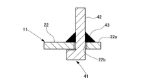
- the soldering portion 41 is formed at an end portion of the lower plate portion 31 and has a pin-shaped connection protrusion (projection piece) 42 as shown in FIGS. 3 and 4.
- connection protrusion 42 is inserted from the lower surface side into the connection hole (hole) 22b formed in the connection end 22a of the branch line portion 22 of the wiring member 11 and penetrates.
- connection protrusion 42 inserted into the connection hole 22 b and the circuit pattern 22 c of the branch line portion 22 in the wiring material 11 are joined by solder 43 on the upper surface side of the wiring material 11.
- connection projecting piece 42 extends from a part of a rectangular frame portion 44 formed on the lower plate portion 31 and is erected upward.
- the frame portion 44 has two vertical frame pieces 44a whose one ends are connected to the lower plate portion 31, and one horizontal frame piece 44b connected to the other end side of these vertical frame pieces 44a.
- the connection projecting piece 42 is connected to the side portion of the central portion of the horizontal frame piece 44b.
- an opening 45 surrounded by the vertical frame piece 44 a, the horizontal frame piece 44 b and the lower plate part 31 is formed in the soldering part 41.
- the bus bar 14 having the above structure is formed of a chain-like bus bar connecting material (connecting material) 51 as shown in FIG.
- the chain-like bus bar connecting member 51 is formed by punching a metal plate.
- the bus bar connecting member 51 has a shape in which ends of a plurality of lower plate portions 31 are connected to each other by a connecting portion 52, and an upper plate portion 32 is connected to each lower plate portion 31 by a hinge portion 33. It is.
- the soldering portion 41 formed on the lower plate portion 31 is a space between the lower plate portion 31 and the upper plate portion 32 between the adjacent lower plate portions 31.
- a space 53 is formed.
- the upper plate portion 32 is overlapped with the lower plate portion 31 by bending at the hinge portion 33.
- the connection protrusions 42 of the soldering portion 41 are raised by being bent in the vicinity of the connecting portion with the horizontal frame piece 44b.
- the lower plate portions 31 that are adjacent to each other are separated by being cut at the connecting portion 52.
- connection end 22a of the branch line portion 22 in the wiring member 11 is connected to the soldering portion 41 of the bus bar 14 formed as described above.
- the solder is inserted into the connection hole 22b formed in the connection end 22a.
- the connection protrusion 42 of the attaching part 41 is inserted.
- the connection end 22a of the branch line portion 22 is held in a state of being positioned with respect to the soldering portion 41.
- connection protrusion 42 that penetrates the connection hole 22b and the circuit pattern 22c (see FIG. 2) of the branch line portion 22 are soldered from above the branch line portion 22.
- the bus bar 14 has a thickness obtained by superposing the lower plate portion 31 and the upper plate portion 32, but the soldering portion 41 is a portion extending from the lower plate portion 31. It is the same thickness as the plate part 31 and is half the thickness of the bus bar 14. That is, the soldering portion 41 has an extremely smaller cross-sectional area than the bus bar 14.
- the soldering portion 41 is formed with an opening 45 surrounded by the vertical frame piece 44 a, the horizontal frame piece 44 b and the lower plate portion 31.
- connection protrusions 42 penetrating the connection hole 22b and the circuit pattern 22c are performed from above the branch line portion 22, the joining state such as the state of the solder 43 at the soldering portion is visually confirmed. be able to.
- the wiring member 11 is erected on the soldering portion 41 having a cross-sectional area smaller than that of the bus bar 14 and is connected to the connection hole 22b of the wiring member 11. Since the cross-sectional area between the pin-like connecting protrusion 42 penetrated and the bus bar 14 becomes small, when connecting the connecting protrusion 42 passing through the connection hole 22b and the circuit pattern 22c of the wiring member 11 to each other, The heat dissipation to the bus bar 14 can be suppressed as much as possible. As a result, the soldering work between the connection protrusions 42 and the circuit pattern 22c can be performed extremely well and in a short time, the bonding by the solder 43 can be stabilized, and high reliability of the connection points can be obtained. .
- the opening 45 is formed in the soldering portion 41, the cross-sectional area between the bus bar 14 and the connection protrusion 42 can be reduced, and heat dissipation to the bus bar 14 during soldering can be further suppressed. .
- the bus bar 14 is configured by stacking the two plate portions of the lower plate portion 31 and the upper plate portion 32, a sufficient cross-sectional area as the bus bar 14 for flowing current is formed even if formed by a thin metal plate having a small cross-sectional area. Can be secured.
- the soldering part 41 is formed in the lower plate part 31, the thickness of the soldering part 41 is halved with respect to the bus bar 14, the cross-sectional area is reduced, and heat dissipation to the bus bar 14 during soldering is suppressed. be able to.
- the soldering portion 41 is half the thickness of the bus bar 14, the connection projecting piece 42 can be easily processed.
- connection protrusions 42 and the circuit pattern 22c can be joined by, for example, ultrasonic joining.
- FIGS. 6 is a plan view of a wiring material according to a reference example
- FIG. 7 is a cross-sectional view taken along line BB in FIG.
- the bus bar 61 is formed with a soldering portion 62 extending from a part of the bus bar 61 at the end thereof.
- the soldering portion 62 is overlaid with the connection end 63a of the branch line portion 63 of the wiring material made of a flexible printed wiring board. Are joined by solder 64.
- connection structure In such a connection structure, heat at the time of soldering is dissipated from the soldering part 62 having the same cross-sectional area as the bus bar 61 to the bus bar 61. Therefore, the joining operation time by soldering becomes long, and the joining by solder becomes unstable, and it becomes difficult to ensure the reliability of the connection location. Further, in the above connection structure, since the joint portion by soldering is hidden by the branch line portion 63 of the wiring material and cannot be visually recognized, it becomes difficult to manage the connection portion.
- connection structure of the wiring material according to the present invention the soldering operation between the projecting piece and the circuit pattern can be performed extremely well in a short time, and stabilization of the joining by soldering can be achieved. Therefore, it is possible to smoothly connect the wiring member to a bus bar connected to a battery mounted on a vehicle such as an electric vehicle or a hybrid car while ensuring high connection reliability.
- Bus bar 22b Connection hole (hole) 22c Circuit pattern 31 Lower plate part (board part) 32 Upper plate (plate) 41 Soldering part 42 Connection protrusion (protrusion) 45 Opening 51 Busbar connecting material (connecting material) 53 Free space
Landscapes
- Chemical & Material Sciences (AREA)
- Chemical Kinetics & Catalysis (AREA)
- Electrochemistry (AREA)
- General Chemical & Material Sciences (AREA)
- Connection Of Batteries Or Terminals (AREA)
- Connections Effected By Soldering, Adhesion, Or Permanent Deformation (AREA)
- Battery Mounting, Suspending (AREA)
- Coupling Device And Connection With Printed Circuit (AREA)
Abstract
Description
(1) バスバーの端部に、該バスバーより断面積の小さい半田付け部が形成され、前記半田付け部にピン状に起立された突片が形成され、前記突片がフレキシブルプリント配線基板からなる配線材の孔部に貫通され、前記孔部を貫通した前記突片と前記配線材の回路パターンとが半田付けされる配線材の接続構造。
しかも、配線材の孔部を貫通した突片と回路パターンとの半田付け箇所における半田の盛り具合などの接合状態を視認することができ、接続箇所の品質管理を容易に行うことができる。
図1に示すように、本発明の一実施形態に係る配線材11は、バッテリ接続プレート12に装着される。このバッテリ接続プレート12は、合成樹脂から成形されたもので、左右両側に、複数のバスバー装着部13が形成されている。これらのバスバー装着部13には、金属板からなるバスバー14が嵌め込まれている。これらのバスバー14には、一対の接続孔14aが形成されており、これらの接続孔14aには、重ね合わされて配置される不図示の複数のバッテリの端子が挿し込まれる。そして、このバッテリの端子にナットを締結することにより、端子がバスバー14と導通した状態に接続される。
半田付け部41は、下板部31の端部に形成されたもので、図3及び図4に示すように、ピン状の接続突片(突片)42を有している。
なお、接続突片42と回路パターン22cとの接合は、例えば、超音波接合も可能である。
図6は参考例に係る配線材の平面図、図7は図6におけるB-B断面図である。
図6及び図7に示すように、バスバー61には、その端部に、バスバー61の一部を伸ばした半田付け部62が形成されている。そして、この半田付け部62には、フレキシブルプリント配線基板からなる配線材の分岐線部63の接続端63aが重ね合わされ、この接続端63aの下面側に露出された回路パターンと半田付け部62との間が半田64によって接合されている。
また、上記の接続構造は、半田付けによる接合箇所が配線材の分岐線部63によって隠れて視認できないので、接続箇所の管理が困難となってしまう。
14 バスバー
22b 接続孔(孔部)
22c 回路パターン
31 下板部(板部)
32 上板部(板部)
41 半田付け部
42 接続突片(突片)
45 開口部
51 バスバー連結材(連結材)
53 空き空間
Claims (4)
- バスバーの端部に、該バスバーより断面積の小さい半田付け部が形成され、
前記半田付け部にピン状に起立された突片が形成され、
前記突片がフレキシブルプリント配線基板からなる配線材の孔部に貫通され、
前記孔部を貫通した前記突片と前記配線材の回路パターンとが半田付けされる配線材の接続構造。 - 前記半田付け部には、開口部が形成されている請求項1に記載の配線材の接続構造。
- 前記バスバーは、2枚の板部を積層して構成され、前記板部の一方に前記半田付け部が形成されている請求項1または請求項2に記載の配線材の接続構造。
- 前記バスバーは、2枚の板部を積層して構成され、前記板部の一方に前記半田付け部が形成されると共に、金属板を打ち抜き加工して連鎖状に形成されたバスバー連結材から成り、
前記半田付け部は、前記バスバー連結材の空き空間に形成される請求項1または請求項2に記載の配線材の接続構造。
Priority Applications (3)
| Application Number | Priority Date | Filing Date | Title |
|---|---|---|---|
| DE112011101397T DE112011101397T5 (de) | 2010-04-22 | 2011-04-12 | Verbindungsstruktur für ein Verdrahtungselement |
| US13/634,785 US9263722B2 (en) | 2010-04-22 | 2011-04-12 | Connection structure for a wiring member |
| CN201180020306.8A CN102859751B (zh) | 2010-04-22 | 2011-04-12 | 用于配线部件的连接结构 |
Applications Claiming Priority (2)
| Application Number | Priority Date | Filing Date | Title |
|---|---|---|---|
| JP2010-099196 | 2010-04-22 | ||
| JP2010099196A JP5715766B2 (ja) | 2010-04-22 | 2010-04-22 | 配線材の接続構造 |
Publications (1)
| Publication Number | Publication Date |
|---|---|
| WO2011132571A1 true WO2011132571A1 (ja) | 2011-10-27 |
Family
ID=44834095
Family Applications (1)
| Application Number | Title | Priority Date | Filing Date |
|---|---|---|---|
| PCT/JP2011/059102 Ceased WO2011132571A1 (ja) | 2010-04-22 | 2011-04-12 | 配線材の接続構造 |
Country Status (5)
| Country | Link |
|---|---|
| US (1) | US9263722B2 (ja) |
| JP (1) | JP5715766B2 (ja) |
| CN (1) | CN102859751B (ja) |
| DE (1) | DE112011101397T5 (ja) |
| WO (1) | WO2011132571A1 (ja) |
Cited By (3)
| Publication number | Priority date | Publication date | Assignee | Title |
|---|---|---|---|---|
| CN102548246A (zh) * | 2012-01-20 | 2012-07-04 | 深圳麦格米特电气股份有限公司 | 一种汇流条、pcb电路板和汇流条贴装方法 |
| CN103427106A (zh) * | 2012-05-21 | 2013-12-04 | 锂能源日本有限公司 | 蓄电装置的制造方法、垫板及蓄电装置 |
| WO2014034809A1 (ja) * | 2012-08-30 | 2014-03-06 | 矢崎総業株式会社 | バスバーモジュール用電線配索構造 |
Families Citing this family (36)
| Publication number | Priority date | Publication date | Assignee | Title |
|---|---|---|---|---|
| US8802275B2 (en) * | 2012-02-23 | 2014-08-12 | Samsung Sdi Co., Ltd. | Battery module |
| JP6257889B2 (ja) * | 2012-10-23 | 2018-01-10 | 日本メクトロン株式会社 | バスバー付きフレキシブルプリント配線板およびその製造方法、並びにバッテリシステム |
| JP5655846B2 (ja) * | 2012-12-04 | 2015-01-21 | 株式会社デンソー | 電力変換装置 |
| JP5910487B2 (ja) * | 2012-12-25 | 2016-04-27 | 株式会社オートネットワーク技術研究所 | 配線用モジュール |
| EP2800168B1 (de) | 2013-04-29 | 2015-10-21 | Samsung SDI Co., Ltd. | Batteriesystem und Verfahren zur Herstellung einer elektrisch leitenden Verbindung zwischen einem Zellverbinder und einer Elektronikeinheit eines Batteriesystems |
| KR20150031093A (ko) | 2013-09-13 | 2015-03-23 | 삼성에스디아이 주식회사 | 이차전지모듈 |
| CN106004512B (zh) * | 2013-12-31 | 2018-06-12 | 比亚迪股份有限公司 | 信号采集组件、动力电池模组、汽车 |
| JP6451650B2 (ja) * | 2014-01-17 | 2019-01-16 | 三洋電機株式会社 | 電源装置 |
| JP6426945B2 (ja) | 2014-08-27 | 2018-11-21 | 株式会社Gsユアサ | 蓄電装置 |
| JP6118305B2 (ja) * | 2014-12-15 | 2017-04-19 | 矢崎総業株式会社 | 電池配線モジュールの製造方法 |
| US10297808B2 (en) * | 2015-04-27 | 2019-05-21 | Sumitomo Electric Industries, Ltd. | Battery wiring module and power supply device provided with battery wiring module |
| KR101623717B1 (ko) | 2015-08-21 | 2016-05-24 | 대산전자(주) | 전기 연결 수단의 제조 방법 |
| CN107732607B (zh) * | 2016-08-12 | 2024-04-09 | 泰科电子(上海)有限公司 | 引线框架、连接组件、信号采样装置及电池包 |
| JP6258437B2 (ja) * | 2016-10-24 | 2018-01-10 | 日本メクトロン株式会社 | バスバー付きフレキシブルプリント配線板の製造方法 |
| KR101928065B1 (ko) | 2016-12-27 | 2018-12-11 | 주식회사 유라코퍼레이션 | 버스바 어셈블리의 연결 구조 |
| KR101928066B1 (ko) * | 2016-12-29 | 2018-12-11 | 주식회사 유라코퍼레이션 | 버스바 어셈블리의 연결 구조 |
| EP3565022B1 (en) * | 2016-12-27 | 2021-03-10 | Yura Corporation Co., Ltd. | Flexible circuit board and frame assembly including same |
| WO2018124751A1 (ko) * | 2016-12-27 | 2018-07-05 | 주식회사 유라코퍼레이션 | 연성회로기판 및 이를 포함하는 프레임 조립체 |
| US11376969B2 (en) | 2016-12-27 | 2022-07-05 | Yura Corporation Co., Ltd. | Bus bar assembly and frame assembly |
| WO2018124494A2 (ko) * | 2016-12-27 | 2018-07-05 | 주식회사 유라코퍼레이션 | 버스바 어셈블리 및 프레임 조립체 |
| JP6856391B2 (ja) * | 2017-01-31 | 2021-04-07 | 矢崎総業株式会社 | バスバー |
| KR102033003B1 (ko) | 2017-02-28 | 2019-10-16 | 주식회사 유라코퍼레이션 | 프레임 조립체 |
| US10741817B2 (en) | 2017-09-20 | 2020-08-11 | Molex, Llc | Battery connection module |
| EP3499655B1 (en) | 2017-12-13 | 2021-03-31 | Aptiv Technologies Limited | Electrical bus bar |
| EP3792996A4 (en) * | 2018-05-09 | 2021-06-16 | GS Yuasa International Ltd. | ENERGY STORAGE DEVICE |
| JP6960090B2 (ja) * | 2018-06-06 | 2021-11-05 | 住友電装株式会社 | バスバー及びバスバー連結体 |
| EP3595037B1 (en) * | 2018-07-10 | 2023-04-19 | Yazaki Corporation | Structure of connection among circuit body, bus bar and electronic element |
| JP7029645B2 (ja) * | 2018-10-02 | 2022-03-04 | 株式会社オートネットワーク技術研究所 | フレキシブルプリント基板、配線部材、蓄電モジュールおよび接続モジュール |
| US11018381B2 (en) * | 2019-02-26 | 2021-05-25 | GM Global Technology Operations LLC | Battery module with interconnect board assembly having integrated cell sense PCB-flex circuit hardware |
| US11058013B2 (en) | 2019-02-26 | 2021-07-06 | GM Global Technology Operations LLC | Method of manufacturing battery module and interconnect board assembly with integrated PCB and flex circuit |
| US12114429B2 (en) | 2019-10-31 | 2024-10-08 | Autonetworks Technologies, Ltd. | Flexible printed circuit board including terminal, wiring module, and power storage module |
| JP7295010B2 (ja) * | 2019-12-23 | 2023-06-20 | 豊田鉄工株式会社 | バスバー |
| KR102344935B1 (ko) * | 2020-02-04 | 2021-12-28 | 한화솔루션 주식회사 | 배터리 센싱 모듈 |
| KR102860571B1 (ko) | 2020-10-14 | 2025-09-15 | 주식회사 엘지에너지솔루션 | 전지 모듈 및 그 제조 방법 |
| JP7638099B2 (ja) * | 2021-01-27 | 2025-03-03 | メクテック株式会社 | 電圧監視モジュール |
| JP7427632B2 (ja) * | 2021-06-25 | 2024-02-05 | 矢崎総業株式会社 | 配線材の接続構造 |
Citations (6)
| Publication number | Priority date | Publication date | Assignee | Title |
|---|---|---|---|---|
| JP2000149909A (ja) * | 1998-09-09 | 2000-05-30 | Yazaki Corp | バッテリ接続プレ―ト |
| JP2006073362A (ja) * | 2004-09-02 | 2006-03-16 | Sanyo Electric Co Ltd | 車両用の電源装置 |
| JP2008288077A (ja) * | 2007-05-18 | 2008-11-27 | Yazaki Corp | 端子の取付構造 |
| JP2008304295A (ja) * | 2007-06-07 | 2008-12-18 | Yazaki Corp | 温度検出器の取付構造 |
| JP2010003466A (ja) * | 2008-06-18 | 2010-01-07 | Autonetworks Technologies Ltd | 電池モジュール |
| JP2010157399A (ja) * | 2008-12-26 | 2010-07-15 | Autonetworks Technologies Ltd | 電池モジュール |
Family Cites Families (10)
| Publication number | Priority date | Publication date | Assignee | Title |
|---|---|---|---|---|
| JPH10308205A (ja) * | 1997-05-09 | 1998-11-17 | Fuji Film Selltec Kk | 電池接続板 |
| JP3613445B2 (ja) | 1999-05-18 | 2005-01-26 | 矢崎総業株式会社 | バッテリ接続プレート |
| JP3707597B2 (ja) * | 1999-10-05 | 2005-10-19 | 矢崎総業株式会社 | バッテリ接続プレートの端子加工装置及び端子加工方法 |
| JP2002374075A (ja) | 2001-06-13 | 2002-12-26 | Fujitsu Ten Ltd | 配線接続方法及び配線接続構造 |
| KR100905391B1 (ko) | 2004-12-24 | 2009-06-30 | 주식회사 엘지화학 | 이차전지 모듈의 단자 연결부재 |
| TWI277381B (en) * | 2005-04-12 | 2007-03-21 | Au Optronics Corp | Double-sided flexible printed circuit board |
| CA2640658A1 (en) * | 2006-02-10 | 2007-08-16 | Opulent Electronics International Pte Ltd. | Anodised aluminium, dielectric, and method |
| JP5026947B2 (ja) * | 2007-12-21 | 2012-09-19 | 矢崎総業株式会社 | 回路基板の熱対策構造 |
| JP5285960B2 (ja) * | 2008-05-27 | 2013-09-11 | 株式会社ケーヒン | 組電池の電源制御装置 |
| JP2010099196A (ja) | 2008-10-22 | 2010-05-06 | Jung Suk Jung | インダクションレンジ用調理器具 |
-
2010
- 2010-04-22 JP JP2010099196A patent/JP5715766B2/ja active Active
-
2011
- 2011-04-12 US US13/634,785 patent/US9263722B2/en active Active
- 2011-04-12 DE DE112011101397T patent/DE112011101397T5/de active Pending
- 2011-04-12 WO PCT/JP2011/059102 patent/WO2011132571A1/ja not_active Ceased
- 2011-04-12 CN CN201180020306.8A patent/CN102859751B/zh active Active
Patent Citations (6)
| Publication number | Priority date | Publication date | Assignee | Title |
|---|---|---|---|---|
| JP2000149909A (ja) * | 1998-09-09 | 2000-05-30 | Yazaki Corp | バッテリ接続プレ―ト |
| JP2006073362A (ja) * | 2004-09-02 | 2006-03-16 | Sanyo Electric Co Ltd | 車両用の電源装置 |
| JP2008288077A (ja) * | 2007-05-18 | 2008-11-27 | Yazaki Corp | 端子の取付構造 |
| JP2008304295A (ja) * | 2007-06-07 | 2008-12-18 | Yazaki Corp | 温度検出器の取付構造 |
| JP2010003466A (ja) * | 2008-06-18 | 2010-01-07 | Autonetworks Technologies Ltd | 電池モジュール |
| JP2010157399A (ja) * | 2008-12-26 | 2010-07-15 | Autonetworks Technologies Ltd | 電池モジュール |
Cited By (6)
| Publication number | Priority date | Publication date | Assignee | Title |
|---|---|---|---|---|
| CN102548246A (zh) * | 2012-01-20 | 2012-07-04 | 深圳麦格米特电气股份有限公司 | 一种汇流条、pcb电路板和汇流条贴装方法 |
| CN103427106A (zh) * | 2012-05-21 | 2013-12-04 | 锂能源日本有限公司 | 蓄电装置的制造方法、垫板及蓄电装置 |
| WO2014034809A1 (ja) * | 2012-08-30 | 2014-03-06 | 矢崎総業株式会社 | バスバーモジュール用電線配索構造 |
| JP2014049238A (ja) * | 2012-08-30 | 2014-03-17 | Yazaki Corp | バスバーモジュール用電線配索構造 |
| CN104603984A (zh) * | 2012-08-30 | 2015-05-06 | 矢崎总业株式会社 | 用于汇流条模块的电线布设结构 |
| US9601743B2 (en) | 2012-08-30 | 2017-03-21 | Yazaki Corporation | Electric wire routing structure for bus bar module |
Also Published As
| Publication number | Publication date |
|---|---|
| JP2011228217A (ja) | 2011-11-10 |
| CN102859751A (zh) | 2013-01-02 |
| CN102859751B (zh) | 2015-09-30 |
| DE112011101397T5 (de) | 2013-03-21 |
| JP5715766B2 (ja) | 2015-05-13 |
| US20130000957A1 (en) | 2013-01-03 |
| US9263722B2 (en) | 2016-02-16 |
Similar Documents
| Publication | Publication Date | Title |
|---|---|---|
| JP5715766B2 (ja) | 配線材の接続構造 | |
| JP3212318U (ja) | 接続部材、接続アセンブリ、バッテリモジュール支持アセンブリ、及びバッテリモジュール | |
| JP4609504B2 (ja) | 電子機器 | |
| JP5080134B2 (ja) | 端子の取付構造 | |
| CN110556501B (zh) | 布线模块及蓄电模块 | |
| US20140198470A1 (en) | Printed circuit board stack | |
| JP5618157B2 (ja) | 電池配線モジュール | |
| CN103875317A (zh) | 用于电动车辆逆变器的功率单元、逆变器和包括所述单元的电动车辆 | |
| JP3193777U (ja) | 接続ボックス | |
| CN112243547B (zh) | 蓄电元件模块 | |
| JP2021516867A (ja) | Fpc接続構造体及びそれを用いた印刷回路基板の接続方法 | |
| CN116457990A (zh) | 配线模块 | |
| US9730326B2 (en) | Electrical contact arrangement for an electric motor and method for producing the same | |
| US20210293854A1 (en) | Current measuring device | |
| JP5039603B2 (ja) | 可撓性接続端子 | |
| JP2025079829A (ja) | 配線モジュール | |
| CN107004816A (zh) | 蓄电模块 | |
| CN108695297B (zh) | 半导体装置、半导体装置的制造方法以及接口单元 | |
| KR101872834B1 (ko) | 배터리 전원 측정을 위한 연결 구조 | |
| JP2017142923A (ja) | バスバー及びバスバーの製造方法 | |
| JP5839099B1 (ja) | プレスフィット用コネクタ端子 | |
| JP5622051B2 (ja) | 基板用端子およびそれを用いた基板用コネクタ | |
| JP4867912B2 (ja) | 樹脂モールドバスバおよびそれを用いた電力変換装置 | |
| JP3177782U (ja) | ジャンクションボックス | |
| JP2010212642A (ja) | プリント配線基板 |
Legal Events
| Date | Code | Title | Description |
|---|---|---|---|
| WWE | Wipo information: entry into national phase |
Ref document number: 201180020306.8 Country of ref document: CN |
|
| 121 | Ep: the epo has been informed by wipo that ep was designated in this application |
Ref document number: 11771906 Country of ref document: EP Kind code of ref document: A1 |
|
| WWE | Wipo information: entry into national phase |
Ref document number: 13634785 Country of ref document: US |
|
| WWE | Wipo information: entry into national phase |
Ref document number: 1120111013973 Country of ref document: DE Ref document number: 112011101397 Country of ref document: DE |
|
| 122 | Ep: pct application non-entry in european phase |
Ref document number: 11771906 Country of ref document: EP Kind code of ref document: A1 |