WO2011118458A1 - 剥離方法および剥離装置 - Google Patents
剥離方法および剥離装置 Download PDFInfo
- Publication number
- WO2011118458A1 WO2011118458A1 PCT/JP2011/056101 JP2011056101W WO2011118458A1 WO 2011118458 A1 WO2011118458 A1 WO 2011118458A1 JP 2011056101 W JP2011056101 W JP 2011056101W WO 2011118458 A1 WO2011118458 A1 WO 2011118458A1
- Authority
- WO
- WIPO (PCT)
- Prior art keywords
- film
- release film
- peeling
- light
- roller
- Prior art date
- Legal status (The legal status is an assumption and is not a legal conclusion. Google has not performed a legal analysis and makes no representation as to the accuracy of the status listed.)
- Ceased
Links
Images

Classifications
-
- B—PERFORMING OPERATIONS; TRANSPORTING
- B65—CONVEYING; PACKING; STORING; HANDLING THIN OR FILAMENTARY MATERIAL
- B65H—HANDLING THIN OR FILAMENTARY MATERIAL, e.g. SHEETS, WEBS, CABLES
- B65H41/00—Machines for separating superposed webs
-
- B—PERFORMING OPERATIONS; TRANSPORTING
- B65—CONVEYING; PACKING; STORING; HANDLING THIN OR FILAMENTARY MATERIAL
- B65H—HANDLING THIN OR FILAMENTARY MATERIAL, e.g. SHEETS, WEBS, CABLES
- B65H23/00—Registering, tensioning, smoothing or guiding webs
- B65H23/04—Registering, tensioning, smoothing or guiding webs longitudinally
- B65H23/18—Registering, tensioning, smoothing or guiding webs longitudinally by controlling or regulating the web-advancing mechanism, e.g. mechanism acting on the running web
- B65H23/188—Registering, tensioning, smoothing or guiding webs longitudinally by controlling or regulating the web-advancing mechanism, e.g. mechanism acting on the running web in connection with running-web
-
- C—CHEMISTRY; METALLURGY
- C09—DYES; PAINTS; POLISHES; NATURAL RESINS; ADHESIVES; COMPOSITIONS NOT OTHERWISE PROVIDED FOR; APPLICATIONS OF MATERIALS NOT OTHERWISE PROVIDED FOR
- C09J—ADHESIVES; NON-MECHANICAL ASPECTS OF ADHESIVE PROCESSES IN GENERAL; ADHESIVE PROCESSES NOT PROVIDED FOR ELSEWHERE; USE OF MATERIALS AS ADHESIVES
- C09J5/00—Adhesive processes in general; Adhesive processes not provided for elsewhere, e.g. relating to primers
-
- C—CHEMISTRY; METALLURGY
- C09—DYES; PAINTS; POLISHES; NATURAL RESINS; ADHESIVES; COMPOSITIONS NOT OTHERWISE PROVIDED FOR; APPLICATIONS OF MATERIALS NOT OTHERWISE PROVIDED FOR
- C09J—ADHESIVES; NON-MECHANICAL ASPECTS OF ADHESIVE PROCESSES IN GENERAL; ADHESIVE PROCESSES NOT PROVIDED FOR ELSEWHERE; USE OF MATERIALS AS ADHESIVES
- C09J7/00—Adhesives in the form of films or foils
- C09J7/20—Adhesives in the form of films or foils characterised by their carriers
- C09J7/22—Plastics; Metallised plastics
-
- C—CHEMISTRY; METALLURGY
- C09—DYES; PAINTS; POLISHES; NATURAL RESINS; ADHESIVES; COMPOSITIONS NOT OTHERWISE PROVIDED FOR; APPLICATIONS OF MATERIALS NOT OTHERWISE PROVIDED FOR
- C09J—ADHESIVES; NON-MECHANICAL ASPECTS OF ADHESIVE PROCESSES IN GENERAL; ADHESIVE PROCESSES NOT PROVIDED FOR ELSEWHERE; USE OF MATERIALS AS ADHESIVES
- C09J7/00—Adhesives in the form of films or foils
- C09J7/40—Adhesives in the form of films or foils characterised by release liners
-
- C—CHEMISTRY; METALLURGY
- C09—DYES; PAINTS; POLISHES; NATURAL RESINS; ADHESIVES; COMPOSITIONS NOT OTHERWISE PROVIDED FOR; APPLICATIONS OF MATERIALS NOT OTHERWISE PROVIDED FOR
- C09J—ADHESIVES; NON-MECHANICAL ASPECTS OF ADHESIVE PROCESSES IN GENERAL; ADHESIVE PROCESSES NOT PROVIDED FOR ELSEWHERE; USE OF MATERIALS AS ADHESIVES
- C09J2301/00—Additional features of adhesives in the form of films or foils
- C09J2301/40—Additional features of adhesives in the form of films or foils characterized by the presence of essential components
-
- C—CHEMISTRY; METALLURGY
- C09—DYES; PAINTS; POLISHES; NATURAL RESINS; ADHESIVES; COMPOSITIONS NOT OTHERWISE PROVIDED FOR; APPLICATIONS OF MATERIALS NOT OTHERWISE PROVIDED FOR
- C09J—ADHESIVES; NON-MECHANICAL ASPECTS OF ADHESIVE PROCESSES IN GENERAL; ADHESIVE PROCESSES NOT PROVIDED FOR ELSEWHERE; USE OF MATERIALS AS ADHESIVES
- C09J2301/00—Additional features of adhesives in the form of films or foils
- C09J2301/50—Additional features of adhesives in the form of films or foils characterized by process specific features
Definitions
- the present invention comprises a pressure-sensitive adhesive layer, a long heavy release film, and a long light release film that can be peeled from the pressure-sensitive adhesive layer with a peeling force smaller than that of the heavy release film. It relates to a peeling method and a peeling device for conveying a long film laminate formed by laminating a film, an adhesive layer and a light release film in this order, and continuously peeling the light release film from the film laminate. is there.
- liquid crystal display device in which polarizing plates are bonded to both sides of a liquid crystal panel is generally manufactured.
- the manufactured liquid crystal display device is modularized and then subjected to various assembling steps to be used as mobile devices such as notebook personal computers and mobile phones, and various products (final products) such as large televisions.
- the polarizing plate is used for bonding to a sheet-like liquid crystal panel by unwinding a long polarizing plate roll wound up in a roll shape and cutting it into a predetermined length.
- the said polarizing plate original fabric is comprised by laminating
- one pressure-sensitive adhesive layer is formed to bond a release film to a polarizing film and to bond the polarizing film to a liquid crystal panel.
- the other pressure-sensitive adhesive layer is formed to bond a protective film to the polarizing film.
- the pressure-sensitive adhesive layer in the polarizing plate is formed by bonding a pressure-sensitive adhesive layer laminated on a release film (and a protective film) to a polarizing film.
- a pressure-sensitive adhesive layer laminated on a release film (and a protective film) comprises a pressure-sensitive adhesive layer, a long heavy release film, and a long light release film that can be peeled from the pressure-sensitive adhesive layer with a release force smaller than that of the heavy release film.
- the adhesive layer and the light release film in this order the adhesive layer is removed.
- the said adhesive layer in a polarizing plate is formed by bonding to a polarizing film.
- the said film laminated body may be called a noncarrier film (what is called a double-sided tape).
- Patent Document 1 describes a separate film peeling apparatus that prevents the tension (tension) of a web from fluctuating when peeling a separate film (lightly peeled film) from a web (film laminate).
- a 1st sheet (lightly peelable film) can be smoothly peeled from a sheet
- seat film laminated body
- 2nd sheet heavy release film and adhesive layer
- the conventional peeling apparatus When peeling the light release film from the film laminate, it is necessary that the pressure-sensitive adhesive layer does not remain on the light release film side.
- the conventional peeling apparatus no special consideration (description) regarding what kind of tension is specifically applied to the film (sheet) corresponding to the heavy release film and the light release film has not been made. Therefore, the conventional peeling apparatus has a problem that the method of peeling the film (sheet) becomes unstable, and an adhesive layer (transfer layer) corresponding to the adhesive layer may remain on the film (sheet) side. ing.
- the present invention has been made in view of the above problems, and its main purpose is to continuously and stably peel the light release film from the film laminate so that the pressure-sensitive adhesive layer does not remain on the light release film side.
- An object of the present invention is to provide a peeling method and a peeling apparatus that can be used.
- the peeling method according to the present invention can peel from the pressure-sensitive adhesive layer with a pressure-sensitive adhesive layer, a long heavy-release film, and a smaller peeling force than the heavy-release film. It consists of a long light release film, and conveys a long film laminate formed by laminating the above heavy release film, pressure-sensitive adhesive layer and light release film in this order, and uses a peeling roller from the film laminate.
- a method for continuously peeling the light release film wherein the tension of the light release film to be conveyed and the tension of the heavy release film are controlled so as to be constant, respectively, with respect to the transport direction of the light release film. The conveyance direction of the heavy release film is changed along the release roller.
- tensile_strength and heavy peeling of the light peeling film conveyed are controlled (tensile control) so that the tension
- the peeling method according to the present invention it is more preferable to change the transport direction of the light release film along the peeling roller.
- the tension of the heavy release film to be conveyed is greater than or equal to the tension of the light release film.
- the angle of the conveyance direction of the heavy peeling film with respect to the conveyance direction of a light peeling film is 35 degrees or more and 180 degrees or less.
- the light release film can be continuously and more stably peeled from the film laminate so that the pressure-sensitive adhesive layer does not remain on the light release film side.
- the end surface in the width direction of the film laminate may be a cut surface. According to said structure, since a light peeling film can be peeled stably continuously, even if the width direction end surface of the film laminated body to peel is a cut surface, that is, a micro unevenness
- the width of the film laminate is more preferably 200 mm or more.
- the peeling device can peel from the pressure-sensitive adhesive layer with a pressure-sensitive adhesive layer, a long heavy-release film, and a peeling force smaller than that of the heavy-release film. It consists of a long light release film and conveys a long film laminate formed by laminating the above heavy release film, pressure-sensitive adhesive layer and light release film in this order, and the light release film from the film laminate.
- a peeling device that continuously peels off, a peeling roller that changes the transport direction of the heavy release film with respect to the transport direction of the light release film, and the tension of the light release film and the tension of the heavy release film that are conveyed are kept constant.
- tensile_strength of the said light peeling film and the heavy peeling film is provided.
- tensile_strength of a heavy peeling film are respectively controlled so that it may become fixed by a control part (Tension control), That is, Since the tension and the tension of the heavy release film are both constant and do not fluctuate, wrinkles are less likely to occur on the light release film and the heavy release film, and the possibility that the release position moves from the release roller is eliminated (the release position is stable). Can be made). Therefore, the light release film can be stably peeled so that the pressure-sensitive adhesive layer does not remain on the light release film side. Thereby, the peeling apparatus which can peel the light peeling film continuously from a film laminated body stably so that an adhesive layer does not remain in the light peeling film side can be provided.
- the peeling apparatus according to the present invention further includes a variable guide roller that arbitrarily changes the angle of the heavy release film in the transport direction with respect to the transport direction of the light release film.
- a variable guide roller that arbitrarily changes the angle of the heavy release film in the transport direction with respect to the transport direction of the light release film.
- the peeling device further includes a transport roller for transporting the lightly peeled film and the heavy peel film after peeling, and the measuring unit is provided on the transport roller, so that the holding angle of the transport roller is constant.
- a fixed guide roller for adjusting the transport direction of the light release film and the heavy release film is further provided between the variable guide roller and the transport roller.
- the tension control by the control unit can be performed more stably.
- the peeling apparatus which can peel a light peeling film continuously and more stably from a film laminated body can be provided.
- the tension of the light release film to be conveyed and the tension of the heavy release film are constant and do not fluctuate so that the pressure-sensitive adhesive layer does not remain on the light release film side.
- the light release film can be stably peeled off.
- FIG. 1 is a front view illustrating a schematic configuration of an example of a peeling apparatus according to the present invention. It is a front view which shows another example of the peeling apparatus which concerns on this invention, and shows a schematic structure.
- the peeling apparatus comprises a pressure-sensitive adhesive layer, a long heavy release film, and a long light release film that can be peeled off from the pressure-sensitive adhesive layer with a peeling force smaller than that of the heavy release film.
- a peeling device that transports a long film laminate formed by laminating the heavy release film, the pressure-sensitive adhesive layer, and the light release film in this order, and continuously peels the light release film from the film laminate.
- a peeling roller that changes the transport direction of the heavy release film relative to the transport direction of the light release film, and a control unit that controls the tension of the light release film and the tension of the heavy release film to be constant, And a measurement unit that measures the tension of the light release film and the tension of the heavy release film.
- the peeling method according to the present invention includes a pressure-sensitive adhesive layer, a long heavy release film, and a long light release film that can be peeled from the pressure-sensitive adhesive layer with a smaller peeling force than the heavy release film.
- a long film laminate formed by laminating the heavy release film, the pressure-sensitive adhesive layer, and the light release film in this order, and continuously using the release roller from the film laminate.
- the peeling direction of the heavy release film is controlled in such a manner that the tension of the light release film to be conveyed and the tension of the heavy release film are controlled to be constant, respectively. Is changed along the peeling roller.
- tension refers to the stress applied per unit time and unit area to the film laminate, light release film or heavy release film.
- the film laminate comprises a pressure-sensitive adhesive layer, a long heavy release film, and a long light release film that can be peeled from the pressure-sensitive adhesive layer with a release force smaller than that of the heavy release film. It is a long film laminate formed by laminating a heavy release film, an adhesive layer and a light release film in this order.
- the said film laminated body may be called a noncarrier film (what is called a double-sided tape).
- Examples of the pressure-sensitive adhesive constituting the pressure-sensitive adhesive layer include known pressure-sensitive adhesives mainly composed of a polymer such as an acrylic resin or a polyurethane resin. In particular, when transparency is required, a known pressure-sensitive adhesive mainly composed of an acrylic resin is more preferable.
- the known pressure-sensitive adhesive is a viscoelastic body, also called a pressure-sensitive adhesive, and adheres to the surface (attachment surface) of the adherend simply by pressing, while the surface (attachment) is peeled off from the adherend. It has the property that it can be peeled off so that no pressure-sensitive adhesive remains on the (surface) side (substantially leaving no trace) (provided that the adherend has sufficient strength to withstand peeling).
- the pressure-sensitive adhesive layer can be formed, for example, by applying a solution obtained by dissolving the pressure-sensitive adhesive in a solvent to the heavy release film or the light release film and drying it.
- the thickness of the said adhesive layer is not specifically limited, Generally it is 5 micrometers or more.
- the heavy release film is a release film (or protective film).
- the heavy release film is composed of a transparent resin film, for example, a polyester resin film such as polyethylene terephthalate, polyethylene naphthalate, and polybutylene terephthalate.
- the light release film is composed of a transparent resin film having a known release treatment on its surface. Accordingly, the light release film can be peeled off from the pressure-sensitive adhesive layer with a peeling force smaller than that of the heavy release film, and the surface subjected to the release treatment is bonded to the pressure-sensitive adhesive layer. It is like that.
- the light release film is composed of a transparent resin film, for example, a polyester resin film such as polyethylene terephthalate, polyethylene naphthalate, or polybutylene terephthalate.
- the film laminate is usually prepared by creating a wide film laminate original and then cutting the film laminate original into a predetermined width. Therefore, the end surface in the width direction of the film laminate is usually a cut surface.
- variety of the said film laminated body is not specifically limited, Generally it is 200 mm or more.
- the elongate film laminated body is generally wound up so that the heavy release film side may become inside.
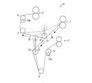
- the peeling device 20 is a peeling device that conveys a long film laminate 30 and continuously peels a light release film 31 from the film laminate 30.
- the peeling device 20 includes a first nip portion 1, a second nip portion 2 and a third nip portion 3, each formed by a pair of nip rollers, a peeling roller 4, guide rollers 5, 6, 7, and conveying rollers 8, 9. It is configured. Each of these rollers is fixed to a casing (not shown) of the peeling device 20.
- the first nip portion 1 has a function of continuously carrying out the long film laminate 30 unwound from the unwinding portion (not shown) toward the peeling roller 4 side.
- the pair of nip rollers that form the first nip portion 1 are provided such that their shaft cores (center axes) are parallel to each other, and are formed of a soft material such as rubber, for example.
- Specific examples of the nip roller include known nip rollers.
- at least one nip roller of the pair of nip rollers is a driving roller, and the rotational speed of the nip roller can be arbitrarily adjusted, and is provided so as to be movable up and down.
- the pressure (nip pressure) can be adjusted as appropriate.
- the second nip portion 2 has a function of continuously conveying the long light release film 31 peeled from the film laminate 30 so as to be wound around a winding portion (not shown).
- the pair of nip rollers that form the second nip portion 2 are provided so that their shaft cores (center axes) are parallel to each other, and are formed of a soft material such as rubber, for example.
- Specific examples of the nip roller include known nip rollers.
- at least one nip roller of the pair of nip rollers is a driving roller, and the rotational speed of the nip roller can be arbitrarily adjusted, and provided so as to be movable up and down.
- the pressure (nip pressure) can be adjusted as appropriate.
- the long heavy release film 32 (laminated body of the heavy release film and the pressure-sensitive adhesive layer) from which the light release film 31 has been peeled is subjected to the next step (for example, a bonding step with a polarizing film). It has the function to convey continuously toward the apparatus (not shown: for example, bonding apparatus) which performs.
- the pair of nip rollers that form the third nip portion 3 are provided so that their shaft cores (center axes) are parallel to each other, and are made of a soft material such as rubber, for example, and the adhesive layer is difficult to adhere thereto. It is made of a material (which does not substantially adhere) or a material whose surface is subjected to a known release treatment.
- at least one nip roller of the pair of nip rollers is a driving roller, and the rotational speed of the nip roller can be arbitrarily adjusted.
- the pressure (nip pressure) can be adjusted as appropriate.
- the heavy release film 32 laminated body of a heavy release film and an adhesive layer
- the peeling roller 4, the guide roller 7, and the conveyance roller 9 It is conveyed to the third nip portion 3 via the.
- the light release film 31 in the film laminate 30 is transported to the second nip portion 2 through the release roller 4, the guide rollers 5 and 6, and the transport roller 8 after being unloaded from the first nip portion 1. It has become so.
- the tension of the heavy release film 32 conveyed between the first nip portion 1 and the third nip portion 3 is controlled (tension control) to be always constant. It is controlled (tension control) so that the tension of the light release film 31 conveyed between the two nip portions 2 is always constant.
- the peeling roller 4 is disposed on the downstream side of the first nip portion 1 (downstream in the transport direction of the film laminate 30) so as to come into contact with the heavy release film 32 side in the film laminate 30.
- the light release film 31 has a function of continuously peeling.
- the peeling roller 4 is a non-driven transport roller, and is formed of a soft material such as rubber or a hard material such as metal. Specific examples of the peeling roller 4 include known (general) rollers. And the peeling roller 4 changes the conveyance direction of the said heavy peeling film 32 with respect to the conveyance direction of the said light peeling film 31.
- the heavy release film 32 in the film laminate 30 in contact with the release roller 4 is conveyed by being wound around the release roller 4 (along the release roller 4) with its transport direction (traveling direction) changed.
- the light release film 31 is conveyed without wrapping around the separation roller 4 (without changing the conveyance direction).
- the peeling roller 4 continuously separates the film laminate 30 into a heavy release film 32 (a laminate of a heavy release film and an adhesive layer) and a light release film 31.
- the guide rollers 5, 6 and 7 are non-driving rollers, and are formed of a soft material such as rubber or a hard material such as metal. Specific examples of the guide rollers 5, 6, and 7 include known (general) rollers.
- the guide rollers 5 and 6 change the transport direction of the light release film 31, and the guide roller 7 changes the transport direction of the heavy release film 32.
- the guide roller 5 is disposed on the downstream side of the peeling roller 4 (downstream in the transport direction of the light release film 31) so as to contact the surface of the light release film 31 that has not been bonded to the adhesive layer. Yes.
- the guide roller 6 is arrange
- the guide roller 7 is disposed on the downstream side of the peeling roller 4 (on the downstream side in the transport direction of the heavy peeling film 32) so as to contact the surface of the heavy peeling film 32 on which the adhesive layer is not bonded. .
- the angle ⁇ in the transport direction of the heavy release film 32 with respect to the transport direction of the light release film 31 is, for example, preferably 35 ° or more and 180 ° or less, more preferably 60 ° or more, 120 It is arranged so that it is less than °.
- the light release film 31 can be continuously and more stably peeled from the film laminate 30 so that the pressure-sensitive adhesive layer does not remain on the light release film 31 side.
- the transport rollers 8 and 9 are non-driving rollers, and are formed of a soft material such as rubber or a hard material such as metal. Specific examples of the transport rollers 8 and 9 include known (general) rollers.
- the conveyance roller 8 is disposed on the downstream side of the guide roller 6 so as to contact the surface of the light release film 31 that has not been bonded to the adhesive layer.
- the conveyance roller 9 is arrange
- the transport roller 8 is provided with a measuring unit 10a for measuring the tension of the light release film 31, and the transport roller 9 is provided with a measuring unit 10b for measuring the tension of the heavy release film 32. Yes. Accordingly, the transport rollers 8 and 9 are so-called tension pickup rollers. Specific examples of the measuring units 10a and 10b include known (general) tension measuring devices. Measurement data measured by the measurement units 10a and 10b is output to a control unit described later.
- the said 2nd nip part 2 is arrange
- the third nip portion 3 is disposed.
- the peeling device 20 analyzes the measurement data input from the measurement units 10a and 10b, and each of the nip rollers that form the first nip portion 1, the second nip portion 2, and the third nip portion 3 according to the analysis result.
- a control unit for controlling (adjusting) various conditions such as the rotation speed and pressure (nip pressure). And what kind of control a control part performs concretely according to an analysis result is previously input (instruction) by users, such as an operator.
- the tension of the light release film 31 and the tension of the heavy release film 32 to be conveyed are controlled to be constant by the control unit (tension control), that is, conveyed. Since the tension of the light release film 31 and the tension of the heavy release film 32 are constant and do not fluctuate, wrinkles are less likely to occur in the light release film 31 and the heavy release film 32, and the release position is determined from the release roller 4. There is no fear of movement (the peeling position can be stabilized). Therefore, the light release film 31 can be stably peeled so that the pressure-sensitive adhesive layer does not remain on the light release film 31 side. Thereby, the peeling apparatus which can peel the light peeling film 31 continuously from the film laminated body 30 stably so that an adhesive layer does not remain in the light peeling film 31 side can be provided.
- tension control tension control
- the film laminate 30, the light release film 31, and the heavy release film 32 are each provided with a constant tension ( And speed).
- And speed a constant tension
- the tension of the light release film 31 to be conveyed is controlled so as to be always constant (tension control).
- the tension of the heavy release film 32 is controlled so as to be always constant (tension control).
- the tension of the light release film 31 and the tension of the heavy release film 32 to be conveyed are each controlled to 50 N or more (tension control), and more preferably 100 N or more. Moreover, it is especially preferable that the tension of the heavy release film 32 to be conveyed is greater than or equal to the tension of the light release film 31. Thereby, the light release film 31 can be continuously and more stably peeled from the film laminate 30 so that the pressure-sensitive adhesive layer does not remain on the light release film 31 side.
- the conveyance speed of the light peeling film 31 conveyed and the conveyance speed of the heavy peeling film 32 are set suitably according to the material and property of these films, thickness, and the said tension
- the film laminate 30 While the film laminate 30 is continuously carried out from the first nip portion 1 and the light release film 31 and the heavy release film 32 are continuously conveyed with the above tension, the film laminate 30 is lightly removed from the film laminate 30 on the release roller 4. The release film 31 is continuously and stably peeled off. Thereafter, the long light release film 31 passes through the second nip portion 2 via the guide rollers 5 and 6 and the conveying roller 8 and is wound around a winding portion (not shown).
- the long heavy peeling film 32 passes through the third nip portion 3 via the guide roller 7 and the conveying roller 9 and performs a next process (for example, a bonding process with a polarizing film) (not shown: For example, it is continuously conveyed toward the bonding apparatus.
- a next process for example, a bonding process with a polarizing film
- the tension of the light release film 31 to be conveyed and the tension of the heavy release film 32 are controlled to be constant (tension control). Since the tension and the tension of the heavy release film 32 are constant and do not fluctuate, wrinkles are less likely to occur in the light release film 31 and the heavy release film 32, and the possibility that the release position moves from the release roller 4 is eliminated ( The peeling position can be stabilized). Therefore, the light release film 31 can be stably peeled so that the pressure-sensitive adhesive layer does not remain on the light release film 31 side. Thereby, the peeling method which can peel the light peeling film 31 continuously from the film laminated body 30 stably so that an adhesive layer does not remain in the light peeling film 31 side can be provided.
- the above-described heavy release film 32 that is, the long heavy release film 32 obtained by peeling the light release film 31 from the pressure-sensitive adhesive layer is suitably used for manufacturing optical films such as polarizing plates and various optical members, for example.
- the said peeling roller 4 in the peeling apparatus 20 which concerns on this Embodiment is comprised with a pair of roller, one roller contacts the heavy peeling film 32 side in the film laminated body 30, and the other roller is the film laminated body 30. It arrange
- the film It is good also as a structure which isolate
- the peeling apparatus 20 is, for example, as a part of a manufacturing apparatus that employs a so-called Roll-to-Panel-type method for manufacturing a liquid crystal display device by continuously bonding a polarizing plate to a sheet-like liquid crystal panel. Preferably used.
- a method for producing a polarizing plate (a polarizing film original fabric) using the heavy release film, and a polarizing plate The manufacturing method of the used liquid crystal panel is demonstrated below with the manufacturing apparatus.
- the polarizing plate is composed of a polarizing film, a protective film (that is, a heavy release film) and an adhesive layer.
- the polarizing film include known polarizing films. More specifically, examples of the polarizing film include known polarizing films in which protective films are bonded to both surfaces of a polarizer film, and an adhesive layer is formed on the protective film.
- the pressure-sensitive adhesive layers one pressure-sensitive adhesive layer is bonded to a polarizing film with a release film (that is, a heavy release film having properties different from the heavy release film serving as the protective film), It is formed for bonding to a liquid crystal panel.
- the other pressure-sensitive adhesive layer is formed to bond a protective film to the polarizing film.
- the thickness of the protective film is not particularly limited, but is generally 10 ⁇ m or more and 100 ⁇ m or less. What is necessary is just to set the thickness of an adhesive layer suitably.
- the thickness of the release film is not particularly limited, but is generally 10 ⁇ m or more and 100 ⁇ m or less.
- the polarizer film examples include, for example, a film made of polyvinyl alcohol, partially formalized polyvinyl alcohol, a partially saponified ethylene-vinyl acetate copolymer, a hydrophilic polymer such as cellulose, a uniaxially stretched, and a pigment such as iodine. And a film subjected to various processes such as hue adjustment.
- the protective film examples include TAC (triacetylcellulose) film, cycloolefin resin film, cellulose acetate resin film such as diacetylcellulose, polyester resin film such as polyethylene terephthalate, polyethylene naphthalate, and polybutylene terephthalate, polycarbonate resin film, Known films such as an acrylic resin film and a polypropylene resin film can be used.
- TAC triacetylcellulose
- cycloolefin resin film such as diacetylcellulose
- polyester resin film such as polyethylene terephthalate, polyethylene naphthalate, and polybutylene terephthalate
- polycarbonate resin film Known films such as an acrylic resin film and a polypropylene resin film can be used.
- the thickness of the polarizing film is not particularly limited, but is generally 10 ⁇ m or more and 300 ⁇ m or less.
- the polarizing film may further include other layers in addition to the above three layers (protective layer, polarizer film, protective layer) as long as there is no practical problem.
- the polarizing film may further include an adhesive layer (may be a pressure-sensitive adhesive layer) that bonds the polarizer film and the protective film.
- the polarizing plate manufacturing apparatus is configured to bond the long heavy release film serving as a release film or a protective film to both sides or one side of the long polarizer film via an adhesive layer.
- the polarizing plate manufacturing apparatus has a transport roller for transporting the polarizer film at a constant speed and a single type of heavy release film or two types of heavy release films having different properties at a constant speed. 1 pair or two sets of transport rollers, and a bonding apparatus having a nip portion for bonding the polarizer film and the heavy release film.
- the polarizing plate manufacturing apparatus conveys both to the nip portion of the laminating apparatus while aligning the heavy release film with respect to the polarizer film, and applies heavy pressure to the polarizer film while applying a predetermined pressure (nip pressure). A film is bonded (bonding operation).
- the polarizing plate manufacturing apparatus may be configured to simultaneously bond two types of heavy release films to both sides of the polarizer film, and to attach the heavy release film to one side of the polarizer film. After bonding, a heavy release film having properties different from those of the heavy release film may be bonded to the other surface. That is, in the polarizing plate manufacturing apparatus, the nip portion of the laminating apparatus performs a single laminating operation in which one heavy release film, the polarizer film, and the other heavy release film are sandwiched (nipped) in this order.
- the polarizing plate may be manufactured with a bonding device, and the bonding apparatus includes two sets of nip portions, and one nip portion is sandwiched (nipped) by sandwiching one heavy release film and a polarizer film. After combining, the other nip portion may be configured to produce a polarizing plate by two bonding operations in which the polarizer film and the other heavy release film are sandwiched (nipped) and bonded. Thereby, a long polarizing plate (a long polarizing plate bonded to a long release film) is produced.
- one of the two types of heavy release films bonded to the polarizer film is a protective film and the other heavy release film is a release film.
- the long polarizing plate has a difference in peeling force between the two types of heavy release films, it is generally wound up so that the side of the heavy release film serving as a protective film is on the inner side to be a long polarizing film original fabric. .
- the polarizing film original fabric is a long polarizing film laminate composed of a polarizing film, a pressure-sensitive adhesive layer, a protective film and a release film, and on the surface of the polarizing film to be bonded to the liquid crystal panel, A release film that can be peeled through an adhesive layer (which may be a pressure-sensitive adhesive layer) is bonded, and on the back surface of the surface, an adhesive layer (may be a pressure-sensitive adhesive layer) is interposed.
- a protective film is bonded.
- a polarizing plate is formed by laminating a pressure-sensitive adhesive layer, a polarizing film, a pressure-sensitive adhesive layer, and a protective film in this order with respect to the release film, and the polarizing film original fabric is formed from the polarizing plate and the release film. It is configured.
- the release film also referred to as a protective film or a separator
- the polarizing plate cut to a predetermined length from the original film of polarizing film covers the entire display area of the liquid crystal panel (the entire surface of the display screen), and is applied to both sides of the liquid crystal panel twice. It is designed to be bonded by a combination process.
- the liquid crystal panel includes a known liquid crystal panel that includes a pair of substrates such as a glass substrate and a liquid crystal layer, and an alignment film is disposed between the substrate and the liquid crystal layer.
- the polarizing film original is unwound by a polarizing film transport mechanism (not shown), and the polarizing plate peeled off from the peeling film is supplied to the nip portion of the laminating apparatus.
- the polarizing film transport mechanism will be described below.
- the polarizing film transport mechanism includes an unwinding unit, a winding unit, a half cutter, a knife edge, and a roller group.
- a long polarizing film original fabric is installed in the unwinding section, and the polarizing film original fabric is unwound.
- the said polarizing film original fabric is wound up by the unwinding part so that the direction of the absorption axis of a polarizing film may be located in the conveyance direction.
- the winding unit winds up a long release film.
- the roller group is provided so that a certain tension is applied to the polarizing film original fabric and the polarizing film original fabric can be conveyed. Accordingly, the polarizing film transport mechanism unwinds the long polarizing film that has been wound up in a roll and transports it to the laminating apparatus, and winds up the unnecessary long release film. .
- the half cutter is provided on the upstream side (unwinding part side) from the knife edge, and the polarizing film original fabric is half-cut to cut the polarizing film, the protective film, and the adhesive layer. That is, the half cutter cuts the long polarizing plate to a predetermined length without cutting the release film.
- a known cutter such as a blade or a laser cutter is preferably used.
- the knife edge is configured to peel the release film from the polarizing plate cut to a predetermined length by the tip.
- the pressure-sensitive adhesive layer formed between the polarizing plate and the release film remains on the polarizing plate side after the release film is peeled off.
- the liquid crystal panel is transported at a constant speed by driving a plurality of transport rollers. Further, the upper pressure roller (and the lower pressure roller) of the laminating apparatus is rotationally driven at a constant rotational speed. This conveying operation is performed throughout the bonding process.
- the polarizing film original fabric is transported at the same transporting speed as that of the liquid crystal panel, and a half cutter
- the long polarizing film is cut into a set length by.
- peeling a long peeling film from a polarizing plate with a knife edge and timing the bonding of the polarizing plate to the liquid crystal panel that is, while aligning the polarizing plate with respect to the liquid crystal panel, It is conveyed to the nip part of the bonding device.
- a polarizing plate is bonded to the liquid crystal panel while applying a predetermined pressure (nip pressure) at the nip portion (bonding step).
- the polarizing plate cut to a predetermined length and peeled off from the release film by the tip of the knife edge is transported while being aligned with the nip portion of the bonding apparatus together with the liquid crystal panel, and bonded to the liquid crystal panel. Is done. That is, the polarizing plate transported to the nip portion is aligned with the liquid crystal panel so as to cover the entire display area of the liquid crystal panel (the entire surface of the display screen) (more specifically, the position of the front end in the transport direction). Are attached to the liquid crystal panel.
- the liquid crystal panel on which the polarizing plate is bonded is conveyed from the nip portion by a plurality of conveying rollers.
- the said bonding process is performed twice, and the liquid crystal display device by which the polarizing plate was bonded on both surfaces of the liquid crystal panel is manufactured.
- the liquid crystal display device is modularized, the liquid crystal display device is further subjected to various assembling processes to be a mobile device such as a notebook personal computer or a mobile phone, and various products (final products) such as a large television.
- the peeling device 21 includes a variable peeling roller 14 instead of the peeling roller 4 in the peeling device 20 according to the embodiment, and a variable guide instead of the guide roller 5.
- a roller 15 is provided.
- the other members constituting the peeling device 21 are the same as the members constituting the peeling device 20.
- the variable peeling roller 14 is arranged on the downstream side of the first nip portion 1 so as to come into contact with the heavy peeling film 32 side in the film laminate 30, and continuously peels the light peeling film 31 from the film laminate 30. It has a function to do.
- the variable peeling roller 14 is a non-driven conveying roller, and is formed of a soft material such as rubber or a hard material such as metal. Specific examples of the variable peeling roller 14 include known (general) rollers.
- the variable peeling roller 14 changes the transport direction of the heavy release film 32 with respect to the transport direction of the light release film 31.
- variable peeling roller 14 is configured to continuously separate the film laminate 30 into a heavy release film 32 (a laminate of a heavy release film and an adhesive layer) and a light release film 31.
- the variable guide roller 15 is a non-driving roller, and is formed of a soft material such as rubber or a hard material such as metal. Specific examples of the variable guide roller 15 include known (general) rollers.
- the variable guide roller 15 is on the downstream side of the variable peeling roller 14 (downstream in the transport direction of the light release film 31) so as to contact the surface of the light release film 31 that has not been bonded to the adhesive layer. Has been placed.
- the variable guide roller 15 changes the transport direction of the light release film 31.
- variable peeling roller 14 and the variable guide roller 15 are provided in a casing (not shown) of the peeling device 21 so as to be movable.
- the variable peeling roller 14 and the variable guide roller 15 depend on the type of the film laminate 30, that is, the material, properties, thickness, etc. of the light release film 31, the adhesive layer and the heavy release film 32.
- the angle ⁇ of the heavy release film 32 in the transport direction with respect to the transport direction of the light release film 31 is, for example, preferably in the range of 35 ° or more and 180 ° or less.
- the arrangement can be changed (position can be moved) so that it can be arbitrarily changed within a range of preferably 60 ° or more and 120 ° or less. Therefore, the variable peeling roller 14 also has a function as a variable guide roller (also serves as).
- the guide rollers 6 and 7 are fixed to a casing (not shown) of the peeling device 21 and have a function as a fixed guide roller. That is, even if the arrangement direction of the variable peeling roller 14 and the variable guide roller 15 is changed (the position is moved), the conveyance direction of the light peeling film 31 from the variable guide roller 15 toward the guide roller 6 is changed. Since the arrangement (position) 6 is fixed and the positional relationship with the conveyance roller 8 does not change, the conveyance direction of the light release film 31 from the guide roller 6 toward the conveyance roller 8 can always be kept constant.
- the guide roller 6 that is a fixed guide roller is provided between the variable guide roller 15 and the conveyance roller 8.
- the direction of transport to go is kept constant. That is, the holding angle (described later) of the light release film 31 in the transport roller 8 can be kept constant. Therefore, the measurement of the tension of the light release film 31 by the measurement unit 10a provided on the transport roller 8 can be stably performed.
- the conveyance roller 9 of the heavy release film 32 since the guide roller 7 that is a fixed guide roller is provided between the variable peeling roller 14 and the conveyance roller 9, the conveyance roller 9 of the heavy release film 32.
- the transport direction toward the head is kept constant. That is, the holding angle of the heavy release film 32 in the transport roller 9 can be kept constant. Therefore, the measurement of the tension of the heavy release film 32 by the measuring unit 10b provided on the transport roller 9 can be stably performed.
- variable guide roller having the same configuration as the variable guide roller 15 may be further provided between the variable peeling roller 14 and the guide roller 7.
- the variable peeling roller 14 does not have (does not serve as) a function as a variable guide roller.
- the “holding angle” is a scale indicating how much the film (light release film 31, heavy release film 32) is wound around the transport rollers 8, 9.
- the angle when the transport direction (traveling direction) is changed by being transported while being in contact with (a value obtained by subtracting 180 ° when the transport direction is not changed is 180 °).
- the transport direction is changed by 60 °, so the holding angle is 120 ° and the 1/4 turn Since the conveyance direction is changed by 90 ° in the case of winding, the holding angle is 90 °, and the conveyance direction is changed by 120 ° in the case of 1 / winding,
- the hugging angle is 60 °, and when the wrapping is 1/2 turn, the conveyance direction is changed by 180 °, so that the hugging angle is 0 °.
- the holding angle of the light release film 31 on the transport roller 8 is always constant. is there.
- the positional relationship among the guide roller 7, the transport roller 9 and the third nip portion 3 is always constant, so that the holding angle of the heavy release film 32 on the transport roller 9 is Always constant.
- the tension of the heavy release film 32 can be stably measured, the tension of the light release film 31 and the heavy release film 32 to be conveyed can be controlled to be always constant.
- the peeling device 21 configured as described above, even if the angle ⁇ in the transport direction of the heavy release film 32 with respect to the transport direction of the light release film 31 is changed,
- the holding angle of the film 31 and the heavy release film 32 can be made constant. That is, since the measurement conditions of the tension of the light release film 31 and the tension of the heavy release film 32 by the measurement units 10a and 10b can always be kept constant, the tension control by the control unit can be performed more stably. Therefore, according to the peeling device 21 having the above-described configuration, the angle of the transport direction of the heavy release film 32 with respect to the transport direction of the light release film 31 can be changed according to the type of the film laminate 30.
- the peeling apparatus which can peel the light peeling film 31 from 30 continuously more stably can be provided.
- the tension of the light release film to be conveyed and the tension of the heavy release film are constant and do not fluctuate so that the pressure-sensitive adhesive layer does not remain on the light release film side.
- the light release film can be stably peeled off.
- the peeling method and the peeling device according to the present invention are suitably used for manufacturing a liquid crystal display device in which polarizing plates are bonded to both surfaces of a liquid crystal panel, for example.
- the liquid crystal display device is modularized and then subjected to various assembling processes, and is widely used in various industries for manufacturing mobile devices such as notebook personal computers and mobile phones, and various products (final products) such as large televisions. Can be used.
Landscapes
- Chemical & Material Sciences (AREA)
- Organic Chemistry (AREA)
- Polarising Elements (AREA)
- Folding Of Thin Sheet-Like Materials, Special Discharging Devices, And Others (AREA)
- Laminated Bodies (AREA)
- Adhesive Tapes (AREA)
- Adhesives Or Adhesive Processes (AREA)
Priority Applications (2)
| Application Number | Priority Date | Filing Date | Title |
|---|---|---|---|
| KR1020127025490A KR101782665B1 (ko) | 2010-03-25 | 2011-03-15 | 박리 방법 및 박리 장치 |
| CN201180015279.5A CN102834339B (zh) | 2010-03-25 | 2011-03-15 | 剥离方法以及剥离装置 |
Applications Claiming Priority (2)
| Application Number | Priority Date | Filing Date | Title |
|---|---|---|---|
| JP2010-069896 | 2010-03-25 | ||
| JP2010069896A JP5185313B2 (ja) | 2010-03-25 | 2010-03-25 | 剥離方法および剥離装置 |
Publications (1)
| Publication Number | Publication Date |
|---|---|
| WO2011118458A1 true WO2011118458A1 (ja) | 2011-09-29 |
Family
ID=44673015
Family Applications (1)
| Application Number | Title | Priority Date | Filing Date |
|---|---|---|---|
| PCT/JP2011/056101 Ceased WO2011118458A1 (ja) | 2010-03-25 | 2011-03-15 | 剥離方法および剥離装置 |
Country Status (5)
| Country | Link |
|---|---|
| JP (1) | JP5185313B2 (enExample) |
| KR (1) | KR101782665B1 (enExample) |
| CN (1) | CN102834339B (enExample) |
| TW (1) | TWI522687B (enExample) |
| WO (1) | WO2011118458A1 (enExample) |
Cited By (6)
| Publication number | Priority date | Publication date | Assignee | Title |
|---|---|---|---|---|
| CN103450821A (zh) * | 2012-05-28 | 2013-12-18 | 祐鼎(福建)光电材料有限公司 | 无基材光学胶带及其制造方法 |
| CN103823268A (zh) * | 2012-11-16 | 2014-05-28 | 日东电工株式会社 | 偏光板的制造方法 |
| WO2018025762A1 (ja) * | 2016-08-02 | 2018-02-08 | 日東電工株式会社 | 剥離方法 |
| JP2021148482A (ja) * | 2020-03-17 | 2021-09-27 | 株式会社村田製作所 | テープの剥離強度測定装置 |
| CN115339218A (zh) * | 2022-08-02 | 2022-11-15 | 拓迪化学(上海)有限公司 | 盖膜剥离装置及其使用方法 |
| CN115816934A (zh) * | 2022-12-09 | 2023-03-21 | 苏州亨利通信材料有限公司 | 一种易剥离钢塑复合带及其制备工艺 |
Families Citing this family (12)
| Publication number | Priority date | Publication date | Assignee | Title |
|---|---|---|---|---|
| JP5856867B2 (ja) * | 2012-02-16 | 2016-02-10 | リンテック株式会社 | 粘着シート、粘着シートの使用方法及び粘着シートの製造方法 |
| JP5903978B2 (ja) * | 2012-03-28 | 2016-04-13 | 住友化学株式会社 | 粘着剤付き光学部材の製造方法 |
| JP6243144B2 (ja) * | 2013-06-11 | 2017-12-06 | リンテック株式会社 | シート貼付装置および貼付方法 |
| JP6203143B2 (ja) * | 2014-07-22 | 2017-09-27 | 住友化学株式会社 | 偏光板の製造方法 |
| KR101701566B1 (ko) | 2014-08-14 | 2017-02-01 | 주식회사 엘지화학 | 패널로부터 편광 필름을 박리하기 위한 박리바, 이를 이용한 박리 장치 및 박리 방법 |
| CN105668305B (zh) * | 2014-11-18 | 2018-01-05 | 赛尔富电子有限公司 | 一种自动化生产设备 |
| JP6812296B2 (ja) * | 2017-04-26 | 2021-01-13 | 住友化学株式会社 | 単層体または積層体の製造方法 |
| CN107498768B (zh) * | 2017-08-18 | 2019-04-05 | 河南玖龙塑料科技有限公司 | 笼式剥离装置 |
| JP6231718B1 (ja) * | 2017-08-25 | 2017-11-15 | 住友化学株式会社 | 偏光板の製造方法 |
| CN107986073A (zh) * | 2017-12-01 | 2018-05-04 | 常德金德新材料科技股份有限公司 | 一种剥离分切机 |
| JP7625908B2 (ja) * | 2021-03-11 | 2025-02-04 | 株式会社リコー | シート処理装置、ラミネート処理装置、画像形成装置及び画像形成システム |
| CN115172989B (zh) * | 2022-08-18 | 2024-03-12 | 江苏星源新材料科技有限公司 | 一种隔膜复合机、隔膜复合方法以及电池隔膜 |
Citations (4)
| Publication number | Priority date | Publication date | Assignee | Title |
|---|---|---|---|---|
| JPH02103049U (enExample) * | 1989-02-01 | 1990-08-16 | ||
| JPH02300054A (ja) * | 1989-05-12 | 1990-12-12 | Toshiba Corp | テープ巻回装置 |
| JPH07196989A (ja) * | 1993-12-31 | 1995-08-01 | Kanegafuchi Chem Ind Co Ltd | カバーテープの剥離方法及び剥離装置 |
| JP2002201439A (ja) * | 2001-01-05 | 2002-07-19 | Dainippon Printing Co Ltd | セパレートフィルム剥離装置 |
Family Cites Families (1)
| Publication number | Priority date | Publication date | Assignee | Title |
|---|---|---|---|---|
| DE19723749A1 (de) * | 1997-06-06 | 1998-12-10 | Koenig & Bauer Albert Ag | Verfahren und Vorrichtung zum Quertrennen von laufenden Bedruckstoffbahnen |
-
2010
- 2010-03-25 JP JP2010069896A patent/JP5185313B2/ja active Active
-
2011
- 2011-03-15 KR KR1020127025490A patent/KR101782665B1/ko active Active
- 2011-03-15 WO PCT/JP2011/056101 patent/WO2011118458A1/ja not_active Ceased
- 2011-03-15 CN CN201180015279.5A patent/CN102834339B/zh active Active
- 2011-03-21 TW TW100109498A patent/TWI522687B/zh active
Patent Citations (4)
| Publication number | Priority date | Publication date | Assignee | Title |
|---|---|---|---|---|
| JPH02103049U (enExample) * | 1989-02-01 | 1990-08-16 | ||
| JPH02300054A (ja) * | 1989-05-12 | 1990-12-12 | Toshiba Corp | テープ巻回装置 |
| JPH07196989A (ja) * | 1993-12-31 | 1995-08-01 | Kanegafuchi Chem Ind Co Ltd | カバーテープの剥離方法及び剥離装置 |
| JP2002201439A (ja) * | 2001-01-05 | 2002-07-19 | Dainippon Printing Co Ltd | セパレートフィルム剥離装置 |
Cited By (10)
| Publication number | Priority date | Publication date | Assignee | Title |
|---|---|---|---|---|
| CN103450821A (zh) * | 2012-05-28 | 2013-12-18 | 祐鼎(福建)光电材料有限公司 | 无基材光学胶带及其制造方法 |
| CN103823268A (zh) * | 2012-11-16 | 2014-05-28 | 日东电工株式会社 | 偏光板的制造方法 |
| WO2018025762A1 (ja) * | 2016-08-02 | 2018-02-08 | 日東電工株式会社 | 剥離方法 |
| JP2018020866A (ja) * | 2016-08-02 | 2018-02-08 | 日東電工株式会社 | 剥離方法 |
| TWI713772B (zh) * | 2016-08-02 | 2020-12-21 | 日商日東電工股份有限公司 | 剝離方法 |
| JP2021148482A (ja) * | 2020-03-17 | 2021-09-27 | 株式会社村田製作所 | テープの剥離強度測定装置 |
| JP7338523B2 (ja) | 2020-03-17 | 2023-09-05 | 株式会社村田製作所 | テープの剥離強度測定装置 |
| CN115339218A (zh) * | 2022-08-02 | 2022-11-15 | 拓迪化学(上海)有限公司 | 盖膜剥离装置及其使用方法 |
| CN115339218B (zh) * | 2022-08-02 | 2024-05-28 | 拓迪化学(上海)股份有限公司 | 盖膜剥离装置及其使用方法 |
| CN115816934A (zh) * | 2022-12-09 | 2023-03-21 | 苏州亨利通信材料有限公司 | 一种易剥离钢塑复合带及其制备工艺 |
Also Published As
| Publication number | Publication date |
|---|---|
| JP5185313B2 (ja) | 2013-04-17 |
| JP2011201999A (ja) | 2011-10-13 |
| CN102834339A (zh) | 2012-12-19 |
| CN102834339B (zh) | 2015-09-16 |
| KR101782665B1 (ko) | 2017-09-27 |
| TW201200944A (en) | 2012-01-01 |
| TWI522687B (zh) | 2016-02-21 |
| KR20130054239A (ko) | 2013-05-24 |
Similar Documents
| Publication | Publication Date | Title |
|---|---|---|
| JP5185313B2 (ja) | 剥離方法および剥離装置 | |
| TWI457637B (zh) | Liquid crystal display device | |
| KR101255497B1 (ko) | 광학표시장치의 제조시스템 | |
| CN103999143B (zh) | 光学显示面板的连续制造方法及光学显示面板的连续制造系统 | |
| JP5613587B2 (ja) | 液晶表示装置の製造方法 | |
| JP5427929B2 (ja) | 光学表示パネルの連続製造方法及び光学表示パネルの連続製造システム | |
| JP4734515B1 (ja) | 光学表示装置の製造システムおよび当該光学表示装置の製造方法 | |
| WO2013133261A1 (ja) | 光学表示パネルの連続製造方法および光学表示パネルの連続製造システム | |
| CN102929029A (zh) | 液晶显示元件的制造方法以及液晶显示元件的制造系统 | |
| JP5314618B2 (ja) | 液晶表示装置の製造方法 | |
| JP5356449B2 (ja) | ナイフエッジおよびこれを含む液晶表示装置の製造システム | |
| JP2011227336A (ja) | 貼合装置 | |
| JP5687930B2 (ja) | 液晶表示装置の製造装置および製造方法 | |
| CN103608718A (zh) | 刀刃以及包含该刀刃的液晶显示装置的制造系统 | |
| JP2014130286A (ja) | 光学表示装置の製造システム |
Legal Events
| Date | Code | Title | Description |
|---|---|---|---|
| WWE | Wipo information: entry into national phase |
Ref document number: 201180015279.5 Country of ref document: CN |
|
| 121 | Ep: the epo has been informed by wipo that ep was designated in this application |
Ref document number: 11759264 Country of ref document: EP Kind code of ref document: A1 |
|
| NENP | Non-entry into the national phase |
Ref country code: DE |
|
| ENP | Entry into the national phase |
Ref document number: 20127025490 Country of ref document: KR Kind code of ref document: A |
|
| 122 | Ep: pct application non-entry in european phase |
Ref document number: 11759264 Country of ref document: EP Kind code of ref document: A1 |