WO2011118053A1 - 産業車両 - Google Patents
産業車両 Download PDFInfo
- Publication number
- WO2011118053A1 WO2011118053A1 PCT/JP2010/060562 JP2010060562W WO2011118053A1 WO 2011118053 A1 WO2011118053 A1 WO 2011118053A1 JP 2010060562 W JP2010060562 W JP 2010060562W WO 2011118053 A1 WO2011118053 A1 WO 2011118053A1
- Authority
- WO
- WIPO (PCT)
- Prior art keywords
- pitching
- pitching control
- vehicle
- actuator
- torque
- Prior art date
Links
Images


Classifications
-
- B—PERFORMING OPERATIONS; TRANSPORTING
- B60—VEHICLES IN GENERAL
- B60W—CONJOINT CONTROL OF VEHICLE SUB-UNITS OF DIFFERENT TYPE OR DIFFERENT FUNCTION; CONTROL SYSTEMS SPECIALLY ADAPTED FOR HYBRID VEHICLES; ROAD VEHICLE DRIVE CONTROL SYSTEMS FOR PURPOSES NOT RELATED TO THE CONTROL OF A PARTICULAR SUB-UNIT
- B60W10/00—Conjoint control of vehicle sub-units of different type or different function
- B60W10/04—Conjoint control of vehicle sub-units of different type or different function including control of propulsion units
- B60W10/06—Conjoint control of vehicle sub-units of different type or different function including control of propulsion units including control of combustion engines
-
- B—PERFORMING OPERATIONS; TRANSPORTING
- B60—VEHICLES IN GENERAL
- B60W—CONJOINT CONTROL OF VEHICLE SUB-UNITS OF DIFFERENT TYPE OR DIFFERENT FUNCTION; CONTROL SYSTEMS SPECIALLY ADAPTED FOR HYBRID VEHICLES; ROAD VEHICLE DRIVE CONTROL SYSTEMS FOR PURPOSES NOT RELATED TO THE CONTROL OF A PARTICULAR SUB-UNIT
- B60W10/00—Conjoint control of vehicle sub-units of different type or different function
- B60W10/02—Conjoint control of vehicle sub-units of different type or different function including control of driveline clutches
-
- B—PERFORMING OPERATIONS; TRANSPORTING
- B60—VEHICLES IN GENERAL
- B60W—CONJOINT CONTROL OF VEHICLE SUB-UNITS OF DIFFERENT TYPE OR DIFFERENT FUNCTION; CONTROL SYSTEMS SPECIALLY ADAPTED FOR HYBRID VEHICLES; ROAD VEHICLE DRIVE CONTROL SYSTEMS FOR PURPOSES NOT RELATED TO THE CONTROL OF A PARTICULAR SUB-UNIT
- B60W10/00—Conjoint control of vehicle sub-units of different type or different function
- B60W10/18—Conjoint control of vehicle sub-units of different type or different function including control of braking systems
- B60W10/184—Conjoint control of vehicle sub-units of different type or different function including control of braking systems with wheel brakes
-
- B—PERFORMING OPERATIONS; TRANSPORTING
- B60—VEHICLES IN GENERAL
- B60W—CONJOINT CONTROL OF VEHICLE SUB-UNITS OF DIFFERENT TYPE OR DIFFERENT FUNCTION; CONTROL SYSTEMS SPECIALLY ADAPTED FOR HYBRID VEHICLES; ROAD VEHICLE DRIVE CONTROL SYSTEMS FOR PURPOSES NOT RELATED TO THE CONTROL OF A PARTICULAR SUB-UNIT
- B60W30/00—Purposes of road vehicle drive control systems not related to the control of a particular sub-unit, e.g. of systems using conjoint control of vehicle sub-units, or advanced driver assistance systems for ensuring comfort, stability and safety or drive control systems for propelling or retarding the vehicle
- B60W30/18—Propelling the vehicle
-
- B—PERFORMING OPERATIONS; TRANSPORTING
- B60—VEHICLES IN GENERAL
- B60W—CONJOINT CONTROL OF VEHICLE SUB-UNITS OF DIFFERENT TYPE OR DIFFERENT FUNCTION; CONTROL SYSTEMS SPECIALLY ADAPTED FOR HYBRID VEHICLES; ROAD VEHICLE DRIVE CONTROL SYSTEMS FOR PURPOSES NOT RELATED TO THE CONTROL OF A PARTICULAR SUB-UNIT
- B60W2520/00—Input parameters relating to overall vehicle dynamics
- B60W2520/16—Pitch
-
- B—PERFORMING OPERATIONS; TRANSPORTING
- B60—VEHICLES IN GENERAL
- B60Y—INDEXING SCHEME RELATING TO ASPECTS CROSS-CUTTING VEHICLE TECHNOLOGY
- B60Y2200/00—Type of vehicle
- B60Y2200/10—Road Vehicles
- B60Y2200/14—Trucks; Load vehicles, Busses
Definitions
- the present invention relates to an industrial vehicle, and more particularly to an industrial vehicle that can suppress the pitching vibration of the vehicle.
- An object of the present invention is to provide an industrial vehicle that can suppress the pitching vibration of the vehicle.
- an industrial vehicle comprising an engine as a power source according to the present invention and a cargo handling device for loading a load, an actuator for applying a driving force or a braking force to the vehicle body, and a pitching vibration of the vehicle body And a pitching control unit that calculates a pitching control torque for reducing pitching vibration and generates a pitching control signal for causing the actuator to output the pitching control torque, and a load.
- the pitching control unit calculates the pitching control torque based on the detection value of the vibration detecting means and outputs the pitching control signal, and the actuator is driven based on the pitching control signal. It is characterized by. *
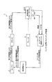
- FIG. 1 is a block diagram showing an industrial vehicle according to an embodiment of the present invention.
- FIG. 2 is a block diagram showing the pitching control unit of the industrial vehicle shown in FIG.
- FIG. 3 is a flowchart showing the operation of the industrial vehicle shown in FIG.
- FIG. 4 is an explanatory view showing the operation of the industrial vehicle shown in FIG.
- FIG. 5 is an explanatory view showing the operation of the industrial vehicle shown in FIG.
- FIG. 6 is a configuration diagram illustrating a modified example of the industrial vehicle illustrated in FIG. 1.
- FIG. 7 is an explanatory view showing a modified example of the industrial vehicle shown in FIG.
- FIG. 8 is a configuration diagram illustrating a modification of the industrial vehicle described in FIG. 1.
- FIG. 9 is an explanatory view showing a modified example of the industrial vehicle shown in FIG.
- FIG. 10 is a configuration diagram illustrating a modified example of the industrial vehicle illustrated in FIG. 1.
- FIG. 11 is an explanatory diagram showing a modification of the industrial vehicle described in FIG. 1.
- FIG. 12 is a configuration diagram illustrating a modified example of the industrial vehicle illustrated in FIG. 1.
- FIG. 13 is a configuration diagram illustrating a modified example of the industrial vehicle illustrated in FIG. 1.
- FIG. 14 is a flowchart showing the actuator selection step.
- FIG. 15 is a table showing actuator selection patterns.
- FIG. 16 is a table showing the relationship between the vehicle configuration and selectable actuators.
- FIG. 17 is an explanatory diagram showing an application example of the industrial vehicle described in FIG. 1.
- FIG. 1 is a block diagram showing an industrial vehicle according to an embodiment of the present invention.
- FIG. 17 is an explanatory diagram showing an application example of the industrial vehicle described in FIG. 1.
- This industrial vehicle is applied to an industrial vehicle (for example, a forklift or a truck) provided with an engine as a power source and a cargo handling device for loading cargo.
- an industrial vehicle for example, a forklift or a truck
- an engine for example, a forklift or a truck
- a cargo handling device for loading cargo for example, a case where an industrial vehicle is applied to a forklift will be described.
- the industrial vehicle 1 includes a vehicle body 2, an engine 3, a clutch 4 and a brake 5, and vehicle control devices 61 and 62 (see FIG. 1). *
- the vehicle body 2 is a four-wheeled vehicle having a front wheel as a driving wheel 21F and a rear wheel as a driven wheel 21R, and has a cargo handling device 23 at the front portion of the vehicle body 22 (see FIG. 17).
- the cargo handling device 23 is a device that raises and lowers the load W, and includes, for example, a lift mechanism 231 that loads and lifts the load W and a drive motor (not shown) for driving the lift mechanism 231. *
- the engine 3, the clutch 4 and the brake 5 are mechanical elements for applying a driving force or a braking force to the vehicle body 22 (see FIG. 1). These engine 3, clutch 4 and brake 5 are widely used in existing industrial vehicles.
- the engine 3 is composed of a direct injection diesel engine, and is connected to the axle (not shown) of the drive wheel 21F via a fluid clutch 4 and a transmission (not shown).
- a vehicle drive device using the engine 3 as a power source is configured.
- the brake 5 is a hydraulic disc brake and is installed on the front and rear wheels 21F and 21R of the vehicle.
- the brake 5 constitutes a vehicle braking device. *
- the vehicle control devices 61 and 62 include a vehicle ECU (Electronic Control Unit) 61, a pitching control unit 62, and various sensors 631 and 632 (see FIG. 1).
- the vehicle ECU 61 is a control unit that mainly controls driving of the engine 3, the clutch 4, and the brake 5, and is mounted on an existing industrial vehicle.
- the pitching control unit 62 is a unit for performing pitching control described later, and is installed independently of the vehicle ECU 61, for example.
- the pitching control unit 62 includes an actuator selection unit 621 that selects an actuator, a pitching control torque calculation unit 622 that calculates a pitching control torque, a pitching control signal generation unit 623 that generates a pitching control signal, and a pitching control unit that is necessary for pitching control. And a storage unit 624 for storing information (see FIG. 2).
- the various sensors 631 and 632 include, for example, a vehicle speed sensor 631 that measures the vehicle speed of the vehicle, a lift pressure sensor 632 that measures the lift pressure (acceleration) of the lift mechanism 231, and the like.
- the vehicle speed sensor 631 and the lift pressure sensor 632 are mounted on an existing industrial vehicle. *
- the industrial vehicle 1 can move the cargo W up and down by the cargo handling device 23, and can travel and move with the cargo W loaded. Further, when the vehicle ECU 61 outputs an engine travel drive signal to the engine 3, the drive of the engine 3 is controlled, and the travel drive torque to the vehicle body 22 is controlled. Further, when the vehicle ECU 61 performs ON / OFF control of the clutch 4, transmission of the driving torque from the engine 3 to the vehicle body 22 is controlled. Thus, driving force control of the vehicle is performed. Further, the vehicle ECU 61 controls the brake 5 by controlling the hydraulic pressure of the brake 5. *
- pitching control is performed in order to suppress pitching vibration during load running (see FIGS. 3 and 4).
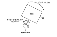
- This pitching control suppresses the pitching vibration by generating a pitching control torque (reverse torque) in the vehicle body 22 using an actuator (for example, the engine 3, the clutch 4, the brake 5, etc.) when the pitching vibration occurs. (See FIG. 4).
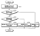
- this pitching control will be described (see FIG. 3). *
- step ST1 the vehicle speed and the lift pressure are acquired.
- the pitching control unit 62 constantly acquires the detection values of the vehicle speed sensor 631 and the lift pressure sensor 632. After this step ST1, the process proceeds to step ST2.
- step ST2 it is determined whether or not the vehicle is running under load. That is, the start condition for pitching control is determined.
- the pitching control unit 62 determines whether or not the vehicle is running under load based on the output value of the lift pressure sensor 632. If an affirmative determination is made in step ST2, the process proceeds to step ST3. If a negative determination is made, the process ends. *
- step ST2 other pitching control start conditions may be determined. For example, when the amplitude of the detection value of the lift pressure sensor 632 is greater than or equal to a predetermined threshold, it is determined that the pitching control is necessary, and the pitching control may be performed. *
- an actuator is selected.
- This actuator is an actuator for generating pitching control torque (reverse torque) in the vehicle body 22.
- the engine 3, the clutch 4, and the brake 5 can generate a pitching control torque in the vehicle body 22 (see FIG. 1). Therefore, any one of the engine 3, the clutch 4, and the brake 5 can be selected as the actuator.
- the actuator is selected based on, for example, the required magnitude of the pitching control torque (required reverse torque) and the vibration frequency of the pitching vibration.
- this step ST3 is omitted when a predetermined actuator is set from the beginning or when there is no choice of actuator.
- the brake 5 is set as a prescribed actuator, and this step ST3 is omitted.
- a pitching control torque is calculated.
- the pitching control torque is a torque (reverse torque) applied to the vehicle body 22 in order to attenuate the pitching vibration of the vehicle body 22.
- This pitching control torque is calculated by the pitching control unit 62 (pitching control torque calculator 622) based on the detected value of the vehicle speed sensor 631 and the detected value of the lift pressure sensor 632.
- the pitching vibration torque (the pitching direction of the vehicle body 22 and the state of the pitching vibration) is calculated based on the detection value of the vehicle speed sensor 631 and the detection value of the lift pressure sensor 632, and based on this torque.
- the pitching control torque is calculated (see FIG. 5).
- the pitching control torque is calculated according to the output characteristics of the actuator selected in step ST3.
- the pitching control torque is calculated according to the output characteristics of the brake 5. That is, when the vehicle is running under load, braking torque is applied to the wheels 21F and 21R (particularly, the front wheels 21F that serve as the axis of pitching vibration) by the ON operation of the brake 5. Therefore, this braking torque is used as the pitching control torque, and the pitching control torque is calculated according to the characteristic of this braking torque (the output characteristic of the brake 5). Specifically, the absolute value of the torque due to the pitching vibration is calculated as the pitching control torque (braking torque of the brake 5). Note that the control period of the pitching control is appropriately set depending on the configuration of the vehicle body 22. After this step ST4, the process proceeds to step ST5. *
- step ST5 a pitching control signal is generated.
- This pitching control signal is a control signal (control signal for driving the actuator) for causing the actuator to output the pitching control torque calculated in step ST4, and is generated by the pitching control unit 62 (pitching control signal generation unit 623). Is done.
- the process proceeds to step ST6.
- step ST6 the actuator is driven based on the pitching control signal (step ST5). Then, the actuator outputs the pitching control torque (step ST4) as a braking force or a driving force (see FIG. 5). Thereby, the reverse torque with respect to a pitching vibration is provided to the vehicle body 22, and the pitching vibration of a vehicle is suppressed (refer FIG. 4).
- the actuator is the brake 5
- the pitching control unit 62 outputs a pitching control signal for the brake 5 to the vehicle ECU 61 (see FIG. 1).
- the vehicle ECU 61 outputs a pitching control signal for the brake 5 to the brake 5, whereby the brake 5 is driven and controlled to generate a braking force corresponding to the pitching control torque.
- the pitching control torque is applied to the vehicle body 22, and the pitching vibration of the vehicle body 22 is suppressed.
- the brake 5 applies braking force corresponding to the pitching control torque to the front wheels 21F of the vehicle, so that the pitching vibration of the vehicle body 22 is effectively suppressed.
- the brake 5 is used as a prescribed actuator that generates pitching control torque.
- the present invention is not limited to this, and the clutch 4 or the engine 3 may be used as a prescribed actuator.
- FIG. 6 and 7 are a configuration diagram (FIG. 6) and an explanatory diagram (FIG. 7) showing a modification of the industrial vehicle shown in FIG.
- FIG. 6 and 7 show a configuration diagram showing a modification of the industrial vehicle shown in FIG.
- a clutch 4 is used as a prescribed actuator for generating pitching control torque (see FIG. 6).
- the torque generated in the vehicle body 22 by the ON / OFF operation of the clutch 4 is used as the pitching control torque (see FIG. 7).
- the pitching control torque calculation step ST4 the pitching vibration torque is calculated based on the detected value of the vehicle speed sensor 631 and the detected value of the lift pressure sensor 632, and based on this torque.
- a pitching control torque is calculated.
- the actuator is the clutch 4
- the pitching control torque is calculated according to the output characteristics of the clutch 4.
- the braking torque generated by the engine brake is applied to the drive wheels (particularly, the front wheels 21F serving as the axis of pitching vibration) by the OFF operation of the clutch 4.
- this braking torque is used as the pitching control torque, and the pitching control torque is calculated according to the characteristic of this braking torque (the output characteristic of the clutch 4).
- the pitching control unit 62 Based on the calculated pitching control torque, the pitching control unit 62 generates a pitching control signal for the clutch 4 (step ST5), and the vehicle ECU 61 controls the driving of the clutch 4 using this pitching control signal ( Step ST6) (see FIGS. 3 and 6). Then, when the clutch 4 is turned on / off, a pitching control torque is applied to the vehicle body 22, and the pitching vibration of the vehicle body 22 is suppressed (see FIG. 4). *
- FIGS. 8 and 9 are a configuration diagram (FIG. 8) and an explanatory diagram (FIG. 9) showing a modified example of the industrial vehicle shown in FIG. 1.
- FIG. 8 and 9 the same components as those described in FIG. 1 are denoted by the same reference numerals, and the description thereof is omitted.
- the engine 3 is used as a prescribed actuator for generating pitching control torque (see FIG. 8).
- the torque generated in the vehicle body 22 by the driving force control of the engine 3 is used as the pitching control torque (see FIG. 9).
- the pitching vibration torque is calculated based on the detected value of the vehicle speed sensor 631 and the detected value of the lift pressure sensor 632, and based on this torque.
- a pitching control torque is calculated.
- the actuator is the engine 3
- the pitching control torque is calculated according to the output characteristics of the engine 3. That is, when the vehicle runs on the engine, the driving force (driving drive torque) of the engine 3 is transmitted to the drive wheels 21F, and the vehicle runs.
- the pitching control torque is added to the driving torque for traveling of the engine 3 and is output, so that the pitching control torque acts on the driving wheels (particularly, the front wheels 21F that serve as the axis of the pitching vibration). Therefore, the pitching control torque is calculated according to the driving force characteristic (output characteristic) of the engine 3.
- the pitching control unit 62 Based on the calculated pitching control torque, the pitching control unit 62 generates a pitching control signal for the engine 3 (step ST5), and the vehicular ECU 61 drives and controls the engine 3 using this pitching control signal (step ST5).
- Step ST6 (see FIGS. 3 and 8).
- the vehicle ECU 61 outputs a control signal obtained by adding the engine travel drive signal and the engine pitching control signal to the engine 3, and based on this control signal, drive control of the engine 3 (for example, fuel control, etc.) ) Is performed.
- the driving force of the engine 3 (the sum of the driving torque for traveling and the pitching control torque) is transmitted to the drive wheels 21F, whereby the pitching control torque is applied to the vehicle body 22. Thereby, the pitching vibration of the vehicle body 22 is suppressed (see FIG. 4). *
- FIG. 10 and 11 are a configuration diagram (FIG. 10) and an explanatory diagram (FIG. 11) showing a modification of the industrial vehicle described in FIG. 1.
- FIG. 10 and 11 are a configuration diagram (FIG. 10) and an explanatory diagram (FIG. 11) showing a modification of the industrial vehicle described in FIG. 1.
- FIG. 10 the same components as those described in FIG. 1 are denoted by the same reference numerals, and the description thereof is omitted.
- the industrial vehicle 1 is a hybrid vehicle including an engine 3 and an electric motor 7 (see FIG. 10).
- Such hybrid systems of hybrid vehicles include a series type, a parallel type, and a series / parallel combination type.
- an industrial vehicle 1 that employs a series / parallel combination type hybrid system will be described.
- the industrial vehicle 1 has (1) a mode in which the driving force (driving driving torque) of the engine 3 is transmitted to the driving wheels 21F, and (2) the engine 3 is stopped to drive the driving force of the electric motor 7 to the driving wheels 21F. And (3) a mode in which electric power is generated by the power of the engine 3 to drive the electric motor 7 and the driving force of the electric motor 7 is transmitted to the drive wheels 21F. Further, (4) during the inertia traveling of the vehicle, the regenerative traveling using the electric motor 7 as a generator can be performed. Drive control of the engine 3 and the electric motor 7 is performed by the vehicle ECU 61. *
- FIG. 10 shows a state in which the vehicle runs on the engine in the mode (1).
- the vehicle ECU 61 outputs an engine travel drive signal to the engine 3, and the engine 3 is driven to generate travel drive torque. And this driving torque for driving
- the engine 3, the clutch 4, and the brake 5 (and the electric motor 7) can be selected as actuators that generate pitching control torque. Pitching control using such an actuator is the same as that described in FIGS. *
- pitching control can be performed by using the electric motor 7 and any one of the engine 3, the clutch 4 and the brake 5 in combination (in cooperation) as an actuator.
- the electric motor 7 and the brake 5 are used as actuators (see FIG. 10).
- Pitching control is performed by applying the driving force of the electric motor 7 and the braking torque of the brake 5 to the vehicle body 22 as pitching control torque (see FIG. 11).
- the pitching control torque calculation step ST4 (see FIG. 3), the pitching vibration torque is calculated based on the detected value of the vehicle speed sensor 631 and the detected value of the lift pressure sensor 632, and based on this torque.
- the pitching control torque by the electric motor 7 and the pitching control torque by the brake 5 are respectively calculated. At this time, the output characteristics of the electric motor 7 and the brake 5 are taken into consideration. For example, in the configuration shown in FIG. 11, torque distribution is preferentially performed on the motor 7 with fast response, and the brake 5 supplements a portion of the necessary pitching control torque amount exceeding the capacity limit value of the motor 7. is doing. *
- the pitching control unit 62 Based on the calculated pitching control torque, the pitching control unit 62 generates a pitching control signal for the electric motor 7 and a pitching control signal for the brake 5 (step ST5), and the vehicle ECU 61 controls these pitching controls.
- the electric motor 7 and the brake 5 are driven and controlled using the signals (step ST6) (see FIGS. 3 and 10). Thereby, the required pitching control torque is applied to the vehicle body 22, and the pitching vibration of the vehicle body 22 is suppressed (see FIG. 4).
- the electric motor 7 and the brake 5 are used together as an actuator (see FIG. 10).
- the present invention is not limited to this, and the electric motor 7 and the clutch 4 may be used together (see FIG. 12), or the electric motor 7 and the engine 3 may be used together (see FIG. 13). *
- FIG. 14 is a flowchart showing the actuator selection step.
- FIG. 15 is a table showing actuator selection patterns.
- the magnitude of the pitching control torque (required reverse torque) necessary for suppressing the pitching vibration in the actuator selection step ST3 (see FIG. 3)
- the vibration frequency of the pitching vibration It is preferable to consider the vibration frequency of the pitching vibration.
- the actuator selection step ST3 is performed as follows (see FIGS. 14 and 15).
- step ST31 the required reverse torque (pitching control torque necessary for suppressing the pitching vibration) and the vibration frequency of the pitching vibration are calculated. These required reverse torque and vibration frequency are calculated based on the detection value of the lift pressure sensor 632 by the pitching control unit 62 (actuator selection unit 621). After step ST31, the process proceeds to step ST32.
- step ST32 it is determined whether the required reverse torque is greater than a predetermined threshold value. This determination is performed by the actuator selection unit 621 comparing the required reverse torque calculated in step ST31 with a predetermined threshold value stored in the storage unit 624. If an affirmative determination is made in step ST32, the process proceeds to step ST33, and if a negative determination is made, the process proceeds to step ST36. *
- step ST33 it is determined whether or not the vibration frequency is higher than a predetermined threshold value. This determination is performed by the actuator selection unit 621 comparing the vibration frequency calculated in step ST31 with a predetermined threshold stored in the storage unit 624. If an affirmative determination is made in step ST33, the process proceeds to step ST34, and if a negative determination is made, the process proceeds to step ST35. *
- step ST34 the electric motor 7 and another actuator (engine 3, clutch 4 or brake 5) are selected as actuators. That is, when the required reverse torque of the pitching vibration is large and the vibration frequency is high (positive determination in step ST32 and positive determination in step ST33), a plurality of actuators are used in combination to perform pitching control (see FIGS. 10 and 11). ). Thereby, a big pitching vibration is suppressed appropriately.
- step ST35 an actuator (engine 3, clutch 4 or brake 5) other than the electric motor 7 is selected. That is, when the required reverse torque of pitching vibration is large but the vibration frequency is low (affirmative determination in step ST32 and negative determination in step ST33), the motor 7 is not used and an actuator of another mechanical system is used. Pitching control is performed. Thereby, since the power consumption of the electric motor 7 is reduced, it is possible to save energy of the system. *
- step ST36 the electric motor 7 is selected as the actuator. That is, when the required reverse torque of the pitching vibration is small (negative determination in step ST32), only the electric motor 7 is used and the pitching control is performed. Therefore, since the pitching control is performed by the electric motor 7 having high responsiveness, the pitching vibration is effectively suppressed. Further, since the required reverse torque of the pitching vibration is small, the power consumption by the electric motor 7 is small.
- step ST36 when the vibration frequency is lower than the predetermined threshold value, the regenerative brake of the electric motor 7 may be used to apply the pitching control torque to the vehicle body 22 (see FIG. 15). That is, in the low frequency region, the pitching vibration can be sufficiently reduced by the pitching control torque using the regenerative brake of the electric motor 7. Thereby, the power consumption of the electric motor 7 is reduced, and the battery can be charged by regenerative running. *
- the actuator that can be used for pitching control differs depending on the system configuration of the industrial vehicle 1 (see FIG. 16). Therefore, the option of the actuator can be appropriately set according to the system configuration of the industrial vehicle 1.
- the industrial vehicle 1 detects the pitching vibration of the actuator (for example, the engine 3, the clutch 4, the brake 5, and the electric motor 7) that applies a driving force or a braking force to the vehicle body 22 and the vehicle body 22.
- a vibration detecting means lift pressure sensor 632
- a pitching control unit 62 for calculating a pitching control torque (reverse torque) for reducing pitching vibration and generating a pitching control signal for causing the actuator to output the pitching control torque; (Refer to FIG. 1, FIG. 6, FIG. 8, FIG. 10, FIG. 12 and FIG. 13).
- the pitching control unit 62 calculates a pitching control torque based on the output value of the vibration detecting means (step ST4), and outputs a pitching control signal (step ST5). (See FIG. 3). Then, the actuator is driven based on this pitching control signal (step ST6).
- feedback control is performed based on the detection value of the vibration detection means, and the pitching control torque is applied to the vehicle body 22 as the driving force or braking force of the actuator (see FIGS. 4, 7, 9, and 11). ).
- Such a configuration is preferable in that an existing vehicle configuration can be used as compared with a configuration in which an accumulator or suspension is additionally provided in the vehicle body and pitching control is performed.
- a lift pressure sensor 632 can be used as vibration detecting means (see FIG. 1).
- vibration detecting means see FIG. 1
- the vehicle brake 5, clutch 4 or engine 3 is used as an actuator for pitching control (see FIGS. 1, 6, 8, 10, 12 and 13).
- the pitching control torque can be applied to the vehicle body 22 using an actuator of an existing engine type vehicle.
- the industrial vehicle 1 including the engine 3 as a power source includes a hybrid industrial vehicle including the engine 3 and the electric motor 7 (see FIGS. 10, 12, and 13). Therefore, in such a hybrid industrial vehicle 1, the vehicle brake 5, clutch 4 or engine 3 may be used as an actuator to perform pitching control. In such a configuration, for example, when the battery charge amount for driving the electric motor 7 is small, there is an advantage that the pitching control can be performed without using the electric motor 7. *
- the electric motor 7 constituting the hybrid system of the vehicle and another actuator for example, any one of the vehicle brake 5, the clutch 4, and the engine 3) are used for pitching control. (See FIGS. 10, 12 and 13). Accordingly, for example, there is an advantage that the pitching vibration can be appropriately suppressed even when the required reverse torque of the pitching vibration is large and the vibration frequency is high.
- the electric motor 7 and another actuator for example, any one of the brake 5 of the vehicle, the clutch 4 and the engine 3) according to the detection value of the vibration detection means (lift pressure sensor 632).
- the actuator can be selected according to the vibration state of the pitching vibration, and therefore, there is an advantage that the responsiveness or energy efficiency of the pitching control can be improved as compared with the configuration in which the specified actuator is set.
- the industrial vehicle according to the present invention is useful in that it can suppress the pitching vibration of the vehicle.
Abstract
この産業車両1は、車体22に駆動力あるいは制動力を付与するブレーキ5と、車体のピッチング振動を検出するリフト圧センサ632と、ピッチング振動を低減させるためのピッチング制御トルクを算出すると共にピッチング制御トルクをブレーキ5に出力させるためのピッチング制御信号を生成するピッチング制御ユニット62とを備えている。そして、車両の負荷走行時にて、ピッチング制御ユニット62がリフト圧センサ632の出力値に基づいてピッチング制御トルクを算出して、ピッチング制御信号を出力する。そして、このピッチング制御信号に基づいて、ブレーキ5が駆動される。
Description
この発明は、産業車両に関し、さらに詳しくは、車両のピッチング振動を抑制できる産業車両に関する。
産業車両では、負荷走行時(荷物を積載して走行しているとき)にて、車体にピッチング振動が発生するという課題がある。このピッチング振動は、車軸を回転軸として車体が前後方向に振動する現象であり、積載された荷物の揺れや運転者の乗心地悪化の原因となるため、好ましくない。かかる課題に関する従来の産業車両として、特許文献1に記載される技術が知られている。
この発明は、車両のピッチング振動を抑制できる産業車両を提供することを目的とする。
上記目的を達成するため、この発明にかかる動力源としてのエンジンと、荷物を積載する荷役装置とを備える産業車両であって、車体に駆動力あるいは制動力を付与するアクチュエータと、車体のピッチング振動を検出する振動検出手段と、ピッチング振動を低減させるためのピッチング制御トルクを算出すると共に前記ピッチング制御トルクを前記アクチュエータに出力させるためのピッチング制御信号を生成するピッチング制御ユニットとを備え、且つ、負荷走行時にて、前記ピッチング制御ユニットが前記振動検出手段の検出値に基づいて前記ピッチング制御トルクを算出して前記ピッチング制御信号を出力すると共に、前記ピッチング制御信号に基づいて前記アクチュエータが駆動されることを特徴とする。
この発明にかかる産業車両は、振動検出手段の検出値に基づいてフィードバック制御が行われ、ピッチング制御トルクがアクチュエータの駆動力あるいは制動力として車体に付与される。これにより、車両のピッチング振動を抑制できる利点がある。
以下、この発明につき図面を参照しつつ詳細に説明する。なお、この実施の形態によりこの発明が限定されるものではない。また、この実施の形態の構成要素には、発明の同一性を維持しつつ置換可能かつ置換自明なものが含まれる。また、この実施の形態に記載された複数の変形例は、当業者自明の範囲内にて任意に組み合わせが可能である。
[産業車両]
図1は、この発明の実施の形態にかかる産業車両を示す構成図である。図17は、図1に記載した産業車両の適用例を示す説明図である。この産業車両は、動力源としてのエンジンと荷物を積載する荷役装置とを備える産業車両(例えば、フォークリフトやトラックなど)に適用される。この実施の形態では、一例として、産業車両がフォークリフトに適用される場合について説明する。
図1は、この発明の実施の形態にかかる産業車両を示す構成図である。図17は、図1に記載した産業車両の適用例を示す説明図である。この産業車両は、動力源としてのエンジンと荷物を積載する荷役装置とを備える産業車両(例えば、フォークリフトやトラックなど)に適用される。この実施の形態では、一例として、産業車両がフォークリフトに適用される場合について説明する。
この産業車両1は、車両本体2と、エンジン3、クラッチ4およびブレーキ5と、車両用制御装置61、62とを備える(図1参照)。
車両本体2は、前輪を駆動輪21Fとし、後輪を従動輪21Rとした四輪自動車であり、車体22の前部に荷役装置23を有する(図17参照)。荷役装置23は、荷物Wを昇降する装置であり、例えば、荷物Wを積載して昇降させるリフト機構231と、このリフト機構231を駆動するための駆動モータ(図示省略)とを有する。
エンジン3、クラッチ4およびブレーキ5は、車体22に駆動力あるいは制動力を付与するための機械要素である(図1参照)。これらのエンジン3、クラッチ4およびブレーキ5は、既存の産業車両に広く採用されている。例えば、この実施の形態では、エンジン3が直噴式ディーゼルエンジンから成り、流体式のクラッチ4および変速機(図示省略)を介して駆動輪21Fの車軸(図示省略)に連結されている。これにより、エンジン3を動力源とした車両の駆動装置が構成されている。また、ブレーキ5が油圧式ディスクブレーキから成り、車両の前後輪21F、21Rに設置されている。このブレーキ5により、車両の制動装置が構成されている。
車両用制御装置61、62は、車両用ECU(Electronic Control Unit)61と、ピッチング制御ユニット62と、各種センサ631、632とを有する(図1参照)。車両用ECU61は、主としてエンジン3、クラッチ4およびブレーキ5の駆動制御を行う制御ユニットであり、既存の産業車両に搭載されている。ピッチング制御ユニット62は、後述するピッチング制御を行うためのユニットであり、例えば、車両用ECU61に対して独立して設置される。このピッチング制御ユニット62は、アクチュエータを選択するアクチュエータ選択部621と、ピッチング制御トルクを算出するピッチング制御トルク算出部622と、ピッチング制御信号を生成するピッチング制御信号生成部623と、ピッチング制御に必要な情報を記憶する記憶部624とを有する(図2参照)。各種センサ631、632は、例えば、車両の車速を測定する車速センサ631、リフト機構231のリフト圧(加速度)を測定するリフト圧センサ632などにより構成される。なお、かかる車速センサ631およびリフト圧センサ632は、既存の産業車両に搭載されている。
この産業車両1は、その荷役装置23にて荷物Wを昇降でき、また、荷物Wを積載したまま走行して移動できる。また、車両用ECU61がエンジン走行用駆動信号をエンジン3に出力することにより、エンジン3が駆動制御されて、車体22への走行用駆動トルクが制御される。また、車両用ECU61がクラッチ4のON/OFF制御を行うことにより、エンジン3から車体22への走行用駆動トルクの伝達が制御される。そして、これらにより、車両の駆動力制御が行われる。また、車両用ECU61がブレーキ5の油圧制御を行うことにより、車両の制動力制御が行われる。
[車両のピッチング制御]
ここで、産業車両では、負荷走行時(荷物Wを積載して走行しているとき)にて、車体にピッチング振動が発生するという課題がある。このピッチング振動は、車軸を回転軸として車体が前後方向に振動する現象であり、積載された荷物Wの揺れや運転者の乗心地悪化の原因となるため、好ましくない。
ここで、産業車両では、負荷走行時(荷物Wを積載して走行しているとき)にて、車体にピッチング振動が発生するという課題がある。このピッチング振動は、車軸を回転軸として車体が前後方向に振動する現象であり、積載された荷物Wの揺れや運転者の乗心地悪化の原因となるため、好ましくない。
そこで、この産業車両1では、負荷走行時のピッチング振動を抑制するために、ピッチング制御が行われる(図3および図4参照)。このピッチング制御は、ピッチング振動が発生したときに、アクチュエータ(例えば、エンジン3、クラッチ4、ブレーキ5など)を用いて車体22にピッチング制御トルク(逆トルク)を発生させることにより、ピッチング振動を抑制する制御である(図4参照)。以下、このピッチング制御について説明する(図3参照)。
ステップST1では、車速およびリフト圧が取得される。例えば、この実施の形態では、ピッチング制御ユニット62が車速センサ631およびリフト圧センサ632の検出値を常時取得している。このステップST1の後に、ステップST2に進む。
ステップST2では、車両が負荷走行中であるか否かが判定される。すなわち、ピッチング制御の開始条件が判定される。例えば、この実施の形態では、ピッチング制御ユニット62がリフト圧センサ632の出力値に基づいて負荷走行中か否かを判定している。このステップST2にて肯定判定が行われた場合には、ステップST3に進み、否定判定が行われた場合には、処理が終了される。
なお、上記のステップST2に加えて、他のピッチング制御の開始条件が判定されても良い。例えば、リフト圧センサ632の検出値の振幅が所定の閾値以上であるときに、ピッチング制御が必要であると判定されて、ピッチング制御が行われても良い。
ステップST3では、アクチュエータの選択が行われる。このアクチュエータは、車体22にピッチング制御トルク(逆トルク)を発生させるためのアクチュエータである。例えば、図1の産業車両1では、エンジン3、クラッチ4およびブレーキ5が車体22にピッチング制御トルクを発生させ得る(図1参照)。したがって、エンジン3、クラッチ4およびブレーキ5のいずれか一つがアクチュエータとして選択され得る。また、アクチュエータの選択は、例えば、要求されるピッチング制御トルクの大きさ(要求逆トルク)やピッチング振動の振動周波数を基準として行われる。このステップST3の後に、ステップST4に進む。
なお、所定のアクチュエータが当初から設定されている場合やアクチュエータの選択肢がない場合には、このステップST3が省略される。例えば、図1の産業車両1では、ブレーキ5が規定のアクチュエータとして設定されており、このステップST3が省略される。
ステップST4では、ピッチング制御トルクが算出される。ピッチング制御トルクは、車体22のピッチング振動を減衰させるために車体22に付与されるトルク(逆トルク)である。このピッチング制御トルクは、ピッチング制御ユニット62(ピッチング制御トルク算出部622)により、車速センサ631の検出値およびリフト圧センサ632の検出値に基づいて算出される。例えば、この実施の形態では、車速センサ631の検出値およびリフト圧センサ632の検出値に基づいてピッチング振動のトルク(車体22のピッチング方向およびピッチング振動の状態)が算出され、このトルクに基づいてピッチング制御トルクが算出されている(図5参照)。また、ピッチング制御トルクは、ステップST3にて選択されたアクチュエータの出力特性に応じて算出される。例えば、この実施の形態では、アクチュエータがブレーキ5であるため、ブレーキ5の出力特性に応じてピッチング制御トルクが算出されている。すなわち、車両の負荷走行時には、ブレーキ5のON動作により車輪21F、21R(特に、ピッチング振動の軸となる前輪21F)に制動トルクが付与される。そこで、この制動トルクがピッチング制御トルクとして用いられ、この制動トルクの特性(ブレーキ5の出力特性)に応じてピッチング制御トルクが算出されている。具体的には、ピッチング振動によるトルクの絶対値がピッチング制御トルク(ブレーキ5の制動トルク)として算出されている。なお、ピッチング制御の制御周期は、車体22の構成によって適宜設定される。このステップST4の後に、ステップST5に進む。
ステップST5では、ピッチング制御信号が生成される。このピッチング制御信号は、ステップST4にて算出されたピッチング制御トルクをアクチュエータに出力させるための制御信号(アクチュエータ駆動用の制御信号)であり、ピッチング制御ユニット62(ピッチング制御信号生成部623)により生成される。このステップST5の後に、ステップST6に進む。
ステップST6では、アクチュエータがピッチング制御信号(ステップST5)に基づいて駆動される。すると、アクチュエータがピッチング制御トルク(ステップST4)を制動力あるいは駆動力として出力する(図5参照)。これにより、ピッチング振動に対する逆トルクが車体22に付与されて、車両のピッチング振動が抑制される(図4参照)。
例えば、この実施の形態では、アクチュエータがブレーキ5であり、ピッチング制御ユニット62がブレーキ5用のピッチング制御信号を車両用ECU61に出力している(図1参照)。そして、車両用ECU61がこのブレーキ5用のピッチング制御信号をブレーキ5に出力することにより、ブレーキ5が駆動制御されてピッチング制御トルクに対応する制動力を発生している。これにより、ピッチング制御トルクが車体22に付与されて、車体22のピッチング振動が抑制されている。
また、この実施の形態では、荷役装置23(リフト機構231)が車体22の前方に配置されるため、ピッチング振動が車両の前輪21Fを軸として発生している(図4および図17参照)。そこで、ブレーキ5がピッチング制御トルクに対応する制動力を車両の前輪21Fに付与することにより、車体22のピッチング振動が効果的に抑制されている。
[クラッチを用いたピッチング制御]
なお、この実施の形態では、ピッチング制御トルクを発生する規定のアクチュエータとして、ブレーキ5が用いられている。しかし、これに限らず、クラッチ4あるいはエンジン3が規定のアクチュエータとして用いられても良い。
なお、この実施の形態では、ピッチング制御トルクを発生する規定のアクチュエータとして、ブレーキ5が用いられている。しかし、これに限らず、クラッチ4あるいはエンジン3が規定のアクチュエータとして用いられても良い。
図6および図7は、図1に記載した産業車両の変形例を示す構成図(図6)および説明図(図7)である。これらの図において、図1に記載した構成要素と同一の構成要素には同一の符号を付し、その説明を省略する。
この産業車両1では、ピッチング制御トルクを発生する規定のアクチュエータとして、クラッチ4が用いられる(図6参照)。そして、このクラッチ4のON/OFF動作により車体22に生ずるトルクが、ピッチング制御トルクとして用いられる(図7参照)。具体的には、ピッチング制御トルクの算出ステップST4(図3参照)にて、車速センサ631の検出値およびリフト圧センサ632の検出値に基づいてピッチング振動のトルクが算出され、このトルクに基づいてピッチング制御トルクが算出される。このとき、アクチュエータがクラッチ4であるため、クラッチ4の出力特性に応じてピッチング制御トルクが算出される。すなわち、車両の慣性走行時あるいは電動機(図示省略)を動力源としたモータ走行時には、クラッチ4のOFF動作により、エンジンブレーキによる制動トルクが駆動輪(特に、ピッチング振動の軸となる前輪21F)に作用する。そこで、この制動トルクがピッチング制御トルクとして用いられ、この制動トルクの特性(クラッチ4の出力特性)に応じてピッチング制御トルクが算出される。
そして、算出されたピッチング制御トルクに基づいて、ピッチング制御ユニット62がクラッチ4用のピッチング制御信号を生成し(ステップST5)、このピッチング制御信号を用いて車両用ECU61がクラッチ4を駆動制御する(ステップST6)(図3および図6参照)。そして、クラッチ4がON/OFF動作することにより、ピッチング制御トルクが車体22に付与されて、車体22のピッチング振動が抑制される(図4参照)。
[エンジンを用いたピッチング制御]
図8および図9は、図1に記載した産業車両の変形例を示す構成図(図8)および説明図(図9)である。これらの図において、図1に記載した構成要素と同一の構成要素には同一の符号を付し、その説明を省略する。
図8および図9は、図1に記載した産業車両の変形例を示す構成図(図8)および説明図(図9)である。これらの図において、図1に記載した構成要素と同一の構成要素には同一の符号を付し、その説明を省略する。
この産業車両1では、ピッチング制御トルクを発生する規定のアクチュエータとして、エンジン3が用いられる(図8参照)。そして、このエンジン3の駆動力制御により車体22に生ずるトルクが、ピッチング制御トルクとして用いられる(図9参照)。具体的には、ピッチング制御トルクの算出ステップST4(図3参照)にて、車速センサ631の検出値およびリフト圧センサ632の検出値に基づいてピッチング振動のトルクが算出され、このトルクに基づいてピッチング制御トルクが算出される。このとき、アクチュエータがエンジン3であるため、エンジン3の出力特性に応じてピッチング制御トルクが算出される。すなわち、車両のエンジン走行時には、エンジン3の駆動力(走行用駆動トルク)が駆動輪21Fに伝達されて車両が走行する。このとき、エンジン3の走行用駆動トルクにピッチング制御トルクが加算されて出力されることにより、ピッチング制御トルクが駆動輪(特に、ピッチング振動の軸となる前輪21F)に作用する。そこで、このエンジン3の駆動力特性(出力特性)に応じてピッチング制御トルクが算出される。
そして、算出されたピッチング制御トルクに基づいて、ピッチング制御ユニット62がエンジン3用のピッチング制御信号を生成し(ステップST5)、このピッチング制御信号を用いて車両用ECU61がエンジン3を駆動制御する(ステップST6)(図3および図8参照)。具体的には、車両用ECU61がエンジン走行用駆動信号とエンジン用ピッチング制御信号とを加算した制御信号をエンジン3に出力し、この制御信号に基づいてエンジン3の駆動制御(例えば、燃料制御など)が行われる。そして、このエンジン3の駆動力(走行用駆動トルクとピッチング制御トルクとを加算したもの)が駆動輪21Fに伝達されることにより、ピッチング制御トルクが車体22に付与される。これにより、車体22のピッチング振動が抑制される(図4参照)。
[ハイブリッド車両のピッチング制御]
図10および図11は、図1に記載した産業車両の変形例を示す構成図(図10)および説明図(図11)である。これらの図において、図1に記載した構成要素と同一の構成要素には同一の符号を付し、その説明を省略する。
図10および図11は、図1に記載した産業車両の変形例を示す構成図(図10)および説明図(図11)である。これらの図において、図1に記載した構成要素と同一の構成要素には同一の符号を付し、その説明を省略する。
この産業車両1は、エンジン3と電動機7とを備えるハイブリッド車両である(図10参照)。かかるハイブリッド車両のハイブリッドシステムには、シリーズ式、パラレル式およびシリーズ/パラレル併用式がある。この実施の形態では、一例として、シリーズ/パラレル併用式のハイブリッドシステムを採用する産業車両1について説明する。かかる産業車両1は、(1)エンジン3の駆動力(走行用駆動トルク)を駆動輪21Fに伝達して走行するモード、(2)エンジン3を停止させて電動機7の駆動力を駆動輪21Fに伝達して走行するモード、および、(3)エンジン3の動力で発電して電動機7を駆動し、電動機7の駆動力を駆動輪21Fに伝達して走行するモードを選択できる。また、(4)車両の慣性走行時にて、電動機7を発電機として用いた回生走行を行い得る。なお、エンジン3および電動機7の駆動制御は、車両用ECU61により行われる。
図10は、車両が上記の(1)のモードにてエンジン走行する状態を示している。かかるエンジン走行時には、車両用ECU61がエンジン3にエンジン走行用の駆動信号を出力し、エンジン3が駆動されて走行用駆動トルクを発生する。そして、この走行用駆動トルクがクラッチ4を介して車両本体2の駆動輪21Fに伝達されて、車両が走行する。
ここで、ハイブリッドシステムを有する産業車両1では、ピッチング制御トルクを発生するアクチュエータとして、エンジン3、クラッチ4およびブレーキ5(さらに、電動機7)を選択し得る。かかるアクチュエータを用いたピッチング制御は、図1~図9に記載した場合と同様である。
また、かかる産業車両1では、アクチュエータとして、電動機7と、エンジン3、クラッチ4およびブレーキ5のいずれか一つとを併用して(協働させて)、ピッチング制御を行い得る。例えば、この実施の形態では、電動機7とブレーキ5とがアクチュエータとして用いられている(図10参照)。そして、電動機7の駆動力とブレーキ5の制動トルクとがピッチング制御トルクとして車体22に付与されることにより、ピッチング制御が行われている(図11参照)。具体的には、ピッチング制御トルクの算出ステップST4(図3参照)にて、車速センサ631の検出値およびリフト圧センサ632の検出値に基づいてピッチング振動のトルクが算出され、このトルクに基づいて、電動機7によるピッチング制御トルクと、ブレーキ5によるピッチング制御トルクとがそれぞれ算出されている。また、このとき、電動機7およびブレーキ5の出力特性が考慮されている。例えば、図11に示す構成では、応答性が速い電動機7に対して優先的にトルク配分が行われ、必要なピッチング制御トルク量のうち電動機7の能力限界値を超える部分を、ブレーキ5が補足している。
そして、算出されたピッチング制御トルクに基づいて、ピッチング制御ユニット62が電動機7用のピッチング制御信号とブレーキ5用のピッチング制御信号とをそれぞれ生成し(ステップST5)、車両用ECU61がこれらのピッチング制御信号を用いて電動機7およびブレーキ5をそれぞれ駆動制御する(ステップST6)(図3および図10参照)。これにより、必要なピッチング制御トルクが車体22に付与されて、車体22のピッチング振動が抑制される(図4参照)。
なお、この実施の形態では、アクチュエータとして、電動機7とブレーキ5とが併用されている(図10参照)。しかし、これに限らず、電動機7とクラッチ4とが併用されても良いし(図12参照)、電動機7とエンジン3とが併用されても良い(図13参照)。
[アクチュエータの選択パターン]
図14は、アクチュエータ選択ステップを示すフローチャートである。図15は、アクチュエータの選択パターンを示す表である。
図14は、アクチュエータ選択ステップを示すフローチャートである。図15は、アクチュエータの選択パターンを示す表である。
上記のようなハイブリッドシステムを備える産業車両1(図10参照)では、アクチュエータ選択ステップST3(図3参照)にあたり、例えば、ピッチング振動の抑制に必要なピッチング制御トルク(要求逆トルク)の大きさや、ピッチング振動の振動周波数などが考慮されることが好ましい。これにより、アクチュエータの選択が適正に行われるので、ピッチング振動が効果的に抑制される。例えば、この実施の形態では、アクチュエータ選択ステップST3が、以下のように行われている(図14および図15参照)。
ステップST31では、要求逆トルク(ピッチング振動の抑制に必要なピッチング制御トルク)およびピッチング振動の振動周波数が算出される。これらの要求逆トルクおよび振動周波数は、ピッチング制御ユニット62(アクチュエータ選択部621)により、リフト圧センサ632の検出値に基づいて算出される。このステップST31の後に、ステップST32に進む。
ステップST32では、要求逆トルクが所定の閾値より大きいか否かが判定される。この判定は、アクチュエータ選択部621がステップST31にて算出された要求逆トルクと記憶部624に記憶された所定の閾値とを比較することにより、行われる。このステップST32にて、肯定判定が行われた場合には、ステップST33に進み、否定判定が行われた場合には、ステップST36に進む。
ステップST33では、振動周波数が所定の閾値より高いか否かが判定される。この判定は、アクチュエータ選択部621がステップST31にて算出された振動周波数と記憶部624に記憶された所定の閾値とを比較することにより、行われる。このステップST33にて、肯定判定が行われた場合には、ステップST34に進み、否定判定が行われた場合には、ステップST35に進む。
ステップST34では、電動機7と、他のアクチュエータ(エンジン3、クラッチ4またはブレーキ5)とがアクチュエータとして選択される。すなわち、ピッチング振動の要求逆トルクが大きく振動周波数が高い場合(ステップST32の肯定判定かつステップST33の肯定判定)には、複数のアクチュエータが併用されてピッチング制御が行われる(図10および図11参照)。これにより、大きなピッチング振動が適切に抑制される。
ステップST35では、電動機7以外のアクチュエータ(エンジン3、クラッチ4またはブレーキ5)が選択される。すなわち、ピッチング振動の要求逆トルクが大きいが振動周波数が低い場合(ステップST32の肯定判定かつステップST33の否定判定)には、電動機7が使用されずに、他の機械系のアクチュエータが用いられてピッチング制御が行われる。これにより、電動機7の消費電力が低減されるので、システムの省エネルギー化が可能となる。
ステップST36では、電動機7がアクチュエータとして選択される。すなわち、ピッチング振動の要求逆トルクが小さい場合(ステップST32の否定判定)には、電動機7のみが用いられてピッチング制御が行われる。したがって、応答性の高い電動機7によりピッチング制御が行われるので、ピッチング振動が効果的に抑制される。また、ピッチング振動の要求逆トルクが小さいので、電動機7による消費電力が小さい。
なお、ステップST36において、振動周波数が所定の閾値よりも低い場合には、電動機7の回生ブレーキが用いられて、ピッチング制御トルクが車体22に付与されても良い(図15参照)。すなわち、低周波領域では、電動機7の回生ブレーキを用いたピッチング制御トルクにより、十分にピッチング振動を低減できる。これにより、電動機7の消費電力が低減されると共に、回生走行によるバッテリの充電が可能となる。
なお、ピッチング制御に使用できるアクチュエータは、産業車両1のシステム構成によって相異する(図16参照)。したがって、アクチュエータの選択肢は、産業車両1のシステム構成に応じて適宜設定され得る。
[効果]
以上説明したように、この産業車両1は、車体22に駆動力あるいは制動力を付与するアクチュエータ(例えば、エンジン3、クラッチ4、ブレーキ5、電動機7など)と、車体22のピッチング振動を検出する振動検出手段(リフト圧センサ632)と、ピッチング振動を低減させるためのピッチング制御トルク(逆トルク)を算出すると共にピッチング制御トルクをアクチュエータに出力させるためのピッチング制御信号を生成するピッチング制御ユニット62とを備える(図1、図6、図8、図10、図12および図13参照)。そして、負荷走行時(ステップST2の肯定判定)にて、ピッチング制御ユニット62が振動検出手段の出力値に基づいてピッチング制御トルクを算出して(ステップST4)、ピッチング制御信号を出力する(ステップST5)(図3参照)。そして、このピッチング制御信号に基づいて、アクチュエータが駆動される(ステップST6)。かかる構成では、振動検出手段の検出値に基づいてフィードバック制御が行われ、ピッチング制御トルクがアクチュエータの駆動力あるいは制動力として車体22に付与される(図4、図7、図9および図11参照)。これにより、車両のピッチング振動を抑制できる利点がある。
以上説明したように、この産業車両1は、車体22に駆動力あるいは制動力を付与するアクチュエータ(例えば、エンジン3、クラッチ4、ブレーキ5、電動機7など)と、車体22のピッチング振動を検出する振動検出手段(リフト圧センサ632)と、ピッチング振動を低減させるためのピッチング制御トルク(逆トルク)を算出すると共にピッチング制御トルクをアクチュエータに出力させるためのピッチング制御信号を生成するピッチング制御ユニット62とを備える(図1、図6、図8、図10、図12および図13参照)。そして、負荷走行時(ステップST2の肯定判定)にて、ピッチング制御ユニット62が振動検出手段の出力値に基づいてピッチング制御トルクを算出して(ステップST4)、ピッチング制御信号を出力する(ステップST5)(図3参照)。そして、このピッチング制御信号に基づいて、アクチュエータが駆動される(ステップST6)。かかる構成では、振動検出手段の検出値に基づいてフィードバック制御が行われ、ピッチング制御トルクがアクチュエータの駆動力あるいは制動力として車体22に付与される(図4、図7、図9および図11参照)。これにより、車両のピッチング振動を抑制できる利点がある。
また、かかる構成では、アキュムレータやサスペンションを車両本体に追設してピッチング制御を行う構成と比較して、既存の車両構成を活用できる点で、好ましい。例えば、この産業車両1では、振動検出手段としてリフト圧センサ632を使用できる(図1参照)。これにより、車両本体2に設置された既存のリフト圧センサ632を用いて、ピッチング振動を検出できる利点がある。
また、この産業車両1では、車両のブレーキ5、クラッチ4あるいはエンジン3がピッチング制御用のアクチュエータとして用いられる(図1、図6、図8、図10、図12および図13参照)。かかる構成では、既存のエンジン式車両のアクチュエータを用いて、ピッチング制御トルクを車体22に付与できる。これにより、既存の車両構成にて、ピッチング制御を行い得る利点がある。
なお、エンジン3を動力源として備える産業車両1には、エンジン3と電動機7とを備えるハイブリッド式の産業車両が含まれる(図10、図12および図13参照)。したがって、かかるハイブリッド式の産業車両1にて、車両のブレーキ5、クラッチ4あるいはエンジン3がアクチュエータとして用いられて、ピッチング制御が行われても良い。かかる構成では、例えば、電動機7を駆動するためのバッテリ充電量が少ないときに、電動機7を用いることなくピッチング制御を行い得る利点がある。
また、この産業車両1では、ハイブリッド車両において、車両のハイブリッドシステムを構成する電動機7と、他のアクチュエータ(例えば、車両のブレーキ5、クラッチ4およびエンジン3のいずれか一つ)とがピッチング制御用のアクチュエータとして併用される(図10、図12および図13参照)。これにより、例えば、ピッチング振動の要求逆トルクが大きく振動周波数が高い場合にも、ピッチング振動を適切に抑制できる利点がある。
また、この産業車両1では、ハイブリッド車両において、振動検出手段(リフト圧センサ632)の検出値に応じて、電動機7と他のアクチュエータ(例えば、車両のブレーキ5、クラッチ4およびエンジン3のいずれか一つ)とがピッチング制御用のアクチュエータとして併用され、あるいは、電動機7および他のアクチュエータ3~5のいずれか一つがピッチング制御用のアクチュエータとして用いられる(図14および図15参照)。かかる構成では、ピッチング振動の振動状態に応じてアクチュエータを選択できるので、規定のアクチュエータが設定されている構成と比較して、ピッチング制御の応答性あるいはエネルギー効率を高め得る利点がある。
以上のように、この発明にかかる産業車両は、車両のピッチング振動を抑制できる点で有用である。
1 産業車両
2 車両本体
21F 前輪(駆動輪)
21R 後輪(従動輪)
22 車体
23 荷役装置
231 リフト機構
3 エンジン
4 クラッチ
5 ブレーキ
61 車両用ECU
62 ピッチング制御ユニット
621 アクチュエータ選択部
622 ピッチング制御トルク算出部
623 ピッチング制御信号生成部
624 記憶部
631 車速センサ
632 リフト圧センサ
7 電動機
2 車両本体
21F 前輪(駆動輪)
21R 後輪(従動輪)
22 車体
23 荷役装置
231 リフト機構
3 エンジン
4 クラッチ
5 ブレーキ
61 車両用ECU
62 ピッチング制御ユニット
621 アクチュエータ選択部
622 ピッチング制御トルク算出部
623 ピッチング制御信号生成部
624 記憶部
631 車速センサ
632 リフト圧センサ
7 電動機
Claims (4)
- 動力源としてのエンジンと、荷物を積載する荷役装置とを備える産業車両であって、
車体に駆動力あるいは制動力を付与するアクチュエータと、車体のピッチング振動を検出する振動検出手段と、ピッチング振動を低減させるためのピッチング制御トルクを算出すると共に前記ピッチング制御トルクを前記アクチュエータに出力させるためのピッチング制御信号を生成するピッチング制御ユニットとを備え、且つ、
負荷走行時にて、前記ピッチング制御ユニットが前記振動検出手段の検出値に基づいて前記ピッチング制御トルクを算出して前記ピッチング制御信号を出力すると共に、前記ピッチング制御信号に基づいて前記アクチュエータが駆動されることを特徴とする産業車両。 - 車両のブレーキ、クラッチあるいはエンジンが前記アクチュエータとして用いられる請求項1に記載の産業車両。
- 車両のハイブリッドシステムを構成する電動機と、他のアクチュエータとが前記アクチュエータとして併用される請求項1に記載の産業車両。
- 前記振動検出手段の検出値に応じて、前記電動機と他のアクチュエータとが前記アクチュエータとして併用され、あるいは、前記電動機および他のアクチュエータのいずれか一つが前記アクチュエータとして用いられる請求項3に記載の産業車両。
Priority Applications (3)
| Application Number | Priority Date | Filing Date | Title |
|---|---|---|---|
| US13/574,750 US20120303225A1 (en) | 2010-03-25 | 2010-06-22 | Industrial vehicle |
| CN201080062778.5A CN102770321B (zh) | 2010-03-25 | 2010-06-22 | 工业车辆 |
| EP10848445.2A EP2557011B1 (en) | 2010-03-25 | 2010-06-22 | Industrial vehicle |
Applications Claiming Priority (2)
| Application Number | Priority Date | Filing Date | Title |
|---|---|---|---|
| JP2010070842A JP5319587B2 (ja) | 2010-03-25 | 2010-03-25 | 産業車両 |
| JP2010-070842 | 2010-03-25 |
Publications (1)
| Publication Number | Publication Date |
|---|---|
| WO2011118053A1 true WO2011118053A1 (ja) | 2011-09-29 |
Family
ID=44672641
Family Applications (1)
| Application Number | Title | Priority Date | Filing Date |
|---|---|---|---|
| PCT/JP2010/060562 WO2011118053A1 (ja) | 2010-03-25 | 2010-06-22 | 産業車両 |
Country Status (5)
| Country | Link |
|---|---|
| US (1) | US20120303225A1 (ja) |
| EP (1) | EP2557011B1 (ja) |
| JP (1) | JP5319587B2 (ja) |
| CN (1) | CN102770321B (ja) |
| WO (1) | WO2011118053A1 (ja) |
Cited By (3)
| Publication number | Priority date | Publication date | Assignee | Title |
|---|---|---|---|---|
| WO2013111736A1 (ja) * | 2012-01-25 | 2013-08-01 | 日産自動車株式会社 | 車両の制御装置及び車両の制御方法 |
| WO2013161537A1 (ja) * | 2012-04-26 | 2013-10-31 | 日産自動車株式会社 | 車両の制御装置及び車両の制御方法 |
| EP2808212A4 (en) * | 2012-01-25 | 2016-03-23 | Nissan Motor | VEHICLE CONTROL SYSTEM AND VEHICLE CONTROL METHOD |
Families Citing this family (23)
| Publication number | Priority date | Publication date | Assignee | Title |
|---|---|---|---|---|
| US10536007B2 (en) | 2011-03-05 | 2020-01-14 | Powin Energy Corporation | Battery energy storage system and control system and applications thereof |
| US9847654B2 (en) | 2011-03-05 | 2017-12-19 | Powin Energy Corporation | Battery energy storage system and control system and applications thereof |
| JP5807684B2 (ja) * | 2012-01-26 | 2015-11-10 | 日産自動車株式会社 | 車両の制御装置及び車両の制御方法 |
| WO2013115006A1 (ja) * | 2012-01-31 | 2013-08-08 | 日産自動車株式会社 | 車両の制御装置 |
| JP5811277B2 (ja) * | 2012-05-14 | 2015-11-11 | 日産自動車株式会社 | 車両の制御装置及び車両の制御方法 |
| US9302893B2 (en) * | 2013-02-07 | 2016-04-05 | The Raymond Corporation | Vibration control systems and methods for industrial lift trucks |
| US9168836B2 (en) * | 2013-12-13 | 2015-10-27 | Powin Energy Corporation | Non-traction battery controller and applications thereof |
| US10263436B2 (en) | 2014-10-20 | 2019-04-16 | Powin Energy Corporation | Electrical energy storage unit and control system and applications thereof |
| US10153521B2 (en) | 2015-08-06 | 2018-12-11 | Powin Energy Corporation | Systems and methods for detecting a battery pack having an operating issue or defect |
| US10254350B2 (en) | 2015-08-06 | 2019-04-09 | Powin Energy Corporation | Warranty tracker for a battery pack |
| US10122186B2 (en) | 2015-09-11 | 2018-11-06 | Powin Energy Corporation | Battery management systems (BMS) having isolated, distributed, daisy-chained battery module controllers |
| US9923247B2 (en) | 2015-09-11 | 2018-03-20 | Powin Energy Corporation | Battery pack with integrated battery management system |
| US10040363B2 (en) | 2015-10-15 | 2018-08-07 | Powin Energy Corporation | Battery-assisted electric vehicle charging system and method |
| US9882401B2 (en) | 2015-11-04 | 2018-01-30 | Powin Energy Corporation | Battery energy storage system |
| US10699278B2 (en) | 2016-12-22 | 2020-06-30 | Powin Energy Corporation | Battery pack monitoring and warranty tracking system |
| CN107601391A (zh) * | 2017-09-22 | 2018-01-19 | 太仓市高泰机械有限公司 | 一种液压车的自动感应及自锁方法 |
| CN107601390A (zh) * | 2017-09-22 | 2018-01-19 | 太仓市高泰机械有限公司 | 一种带有自锁功能的液压车的工作方法 |
| CN107458999A (zh) * | 2017-09-22 | 2017-12-12 | 太仓市高泰机械有限公司 | 一种带有阻尼减震装置的自调型液压车 |
| CN107352473A (zh) * | 2017-09-22 | 2017-11-17 | 太仓市高泰机械有限公司 | 一种自调型液压车的工作方法 |
| CN110094436A (zh) * | 2019-03-29 | 2019-08-06 | 北京汽车股份有限公司 | 离合器控制方法、装置、计算机可读存储介质及车辆 |
| JP7340379B2 (ja) * | 2019-08-02 | 2023-09-07 | 日立建機株式会社 | ホイール式の作業車両 |
| JP7319884B2 (ja) | 2019-09-27 | 2023-08-02 | 株式会社Subaru | パワーユニットの振動抑制装置 |
| JP2021134022A (ja) | 2020-02-25 | 2021-09-13 | 三菱重工業株式会社 | 荷役車両の振動防止システム及び荷役車両 |
Citations (7)
| Publication number | Priority date | Publication date | Assignee | Title |
|---|---|---|---|---|
| JPS6212305A (ja) * | 1985-07-06 | 1987-01-21 | Toyota Motor Corp | 電気自動車のピツチング抑制装置 |
| JPH03284461A (ja) * | 1990-03-31 | 1991-12-16 | Toyo Umpanki Co Ltd | 車両のピッチング抑制装置 |
| JP2004129459A (ja) * | 2002-10-07 | 2004-04-22 | Meidensha Corp | 速度指令制御部及び電動車輌の速度制御装置 |
| JP2006060936A (ja) * | 2004-08-20 | 2006-03-02 | Denso Corp | 車両挙動制御システム |
| JP2006224687A (ja) * | 2005-02-15 | 2006-08-31 | Denso Corp | 車両制御装置 |
| JP2009113772A (ja) * | 2007-11-09 | 2009-05-28 | Toyota Motor Corp | 車両の制動力および駆動力の制御装置 |
| JP2010081684A (ja) * | 2008-09-24 | 2010-04-08 | Toyota Industries Corp | 産業車両のピッチング抑制装置 |
Family Cites Families (10)
| Publication number | Priority date | Publication date | Assignee | Title |
|---|---|---|---|---|
| JPH08297026A (ja) * | 1995-04-27 | 1996-11-12 | Komatsu Ltd | 上部旋回式建設機械のピッチング制振装置 |
| FR2814985A1 (fr) * | 2000-10-11 | 2002-04-12 | Conception & Dev Michelin Sa | Dispositif de suspension comportant un verin electrique et un ressort en parallele |
| CN101696659B (zh) * | 2003-09-02 | 2014-11-12 | 株式会社小松制作所 | 发动机控制装置 |
| JP4123145B2 (ja) * | 2003-12-02 | 2008-07-23 | 株式会社明電舎 | 電動車輛の速度制御装置 |
| JP4515201B2 (ja) * | 2004-09-06 | 2010-07-28 | 株式会社デンソー | 車両安定化制御システム |
| JP2007238301A (ja) * | 2006-03-10 | 2007-09-20 | Toyota Industries Corp | フォークリフトにおける振動吸収装置 |
| JP4878062B2 (ja) * | 2007-03-05 | 2012-02-15 | 国立大学法人横浜国立大学 | 自動車のピッチング制御装置および制御方法 |
| US7997363B2 (en) * | 2007-09-17 | 2011-08-16 | Denso Corporation | Vehicle control system and method |
| US8322728B2 (en) * | 2007-09-28 | 2012-12-04 | Hitachi, Ltd. | Suspension control apparatus |
| JP5171594B2 (ja) * | 2008-12-15 | 2013-03-27 | 日立建機株式会社 | 電動車両及びそのピッチング制御装置 |
-
2010
- 2010-03-25 JP JP2010070842A patent/JP5319587B2/ja active Active
- 2010-06-22 EP EP10848445.2A patent/EP2557011B1/en active Active
- 2010-06-22 CN CN201080062778.5A patent/CN102770321B/zh active Active
- 2010-06-22 US US13/574,750 patent/US20120303225A1/en not_active Abandoned
- 2010-06-22 WO PCT/JP2010/060562 patent/WO2011118053A1/ja active Application Filing
Patent Citations (8)
| Publication number | Priority date | Publication date | Assignee | Title |
|---|---|---|---|---|
| JPS6212305A (ja) * | 1985-07-06 | 1987-01-21 | Toyota Motor Corp | 電気自動車のピツチング抑制装置 |
| JPH03284461A (ja) * | 1990-03-31 | 1991-12-16 | Toyo Umpanki Co Ltd | 車両のピッチング抑制装置 |
| JP2004129459A (ja) * | 2002-10-07 | 2004-04-22 | Meidensha Corp | 速度指令制御部及び電動車輌の速度制御装置 |
| JP3935039B2 (ja) | 2002-10-07 | 2007-06-20 | 株式会社明電舎 | 速度指令制御部及び電動車輌の速度制御装置 |
| JP2006060936A (ja) * | 2004-08-20 | 2006-03-02 | Denso Corp | 車両挙動制御システム |
| JP2006224687A (ja) * | 2005-02-15 | 2006-08-31 | Denso Corp | 車両制御装置 |
| JP2009113772A (ja) * | 2007-11-09 | 2009-05-28 | Toyota Motor Corp | 車両の制動力および駆動力の制御装置 |
| JP2010081684A (ja) * | 2008-09-24 | 2010-04-08 | Toyota Industries Corp | 産業車両のピッチング抑制装置 |
Cited By (5)
| Publication number | Priority date | Publication date | Assignee | Title |
|---|---|---|---|---|
| WO2013111736A1 (ja) * | 2012-01-25 | 2013-08-01 | 日産自動車株式会社 | 車両の制御装置及び車両の制御方法 |
| EP2808212A4 (en) * | 2012-01-25 | 2016-03-23 | Nissan Motor | VEHICLE CONTROL SYSTEM AND VEHICLE CONTROL METHOD |
| US9415657B2 (en) | 2012-01-25 | 2016-08-16 | Nissan Motor Co., Ltd. | Vehicle control device and vehicle control method |
| WO2013161537A1 (ja) * | 2012-04-26 | 2013-10-31 | 日産自動車株式会社 | 車両の制御装置及び車両の制御方法 |
| JPWO2013161537A1 (ja) * | 2012-04-26 | 2015-12-24 | 日産自動車株式会社 | 車両の制御装置及び車両の制御方法 |
Also Published As
| Publication number | Publication date |
|---|---|
| US20120303225A1 (en) | 2012-11-29 |
| EP2557011A1 (en) | 2013-02-13 |
| EP2557011B1 (en) | 2019-06-05 |
| CN102770321B (zh) | 2015-08-05 |
| JP2011201433A (ja) | 2011-10-13 |
| EP2557011A4 (en) | 2018-04-18 |
| CN102770321A (zh) | 2012-11-07 |
| JP5319587B2 (ja) | 2013-10-16 |
Similar Documents
| Publication | Publication Date | Title |
|---|---|---|
| JP5319587B2 (ja) | 産業車両 | |
| JP5596756B2 (ja) | 電動車両 | |
| JPH08163707A (ja) | 電気自動車の制動制御装置 | |
| JP7038971B2 (ja) | 車両の制御方法、車両システム及び車両の制御装置 | |
| JP5325120B2 (ja) | ハイブリッド車両のエネルギ管理方法及び装置 | |
| JP2014527392A (ja) | 車両の減速構成を制御する方法 | |
| JP2006060936A (ja) | 車両挙動制御システム | |
| CN102756733A (zh) | 优化的车辆牵引力控制 | |
| JP2009273275A (ja) | 車両の制御装置 | |
| EP3738816A1 (en) | Vehicle control method, and control device for vehicle system and vehicle | |
| CN103895631B (zh) | 再生制动协调控制方法及混合动力汽车 | |
| CN104540716A (zh) | 机动车的发电机式制动系统的控制装置和用于机动车的发电机式制动系统的运行方法 | |
| JP2009173089A (ja) | 車両の制御装置 | |
| JP2010241166A (ja) | 車両の四輪駆動制御装置及び四輪駆動制御方法 | |
| KR101337903B1 (ko) | Abs 작동시 진동 저감을 위한 모터 제어 방법 | |
| JP5872780B2 (ja) | 気動車用エンジン制御装置 | |
| JP2011088492A (ja) | ハイブリッド車両のトラクション制御装置 | |
| JP7377432B2 (ja) | 車両の制御システム | |
| JP4453643B2 (ja) | ハイブリッド車両の駆動力源切替制御装置 | |
| CN104553822A (zh) | 电机牵引力矩补偿 | |
| JP2022012210A (ja) | 車両駆動システム | |
| JP2000274270A (ja) | ハイブリッド車の車両走行制御装置 | |
| JP4581406B2 (ja) | 回生制動制御装置 | |
| JP2007153127A (ja) | 車両の制御装置 | |
| US20170072941A1 (en) | Expanding regenerative capacity up to vehicle dynamic limits through integration with mitigative subsystems |
Legal Events
| Date | Code | Title | Description |
|---|---|---|---|
| WWE | Wipo information: entry into national phase |
Ref document number: 201080062778.5 Country of ref document: CN |
|
| 121 | Ep: the epo has been informed by wipo that ep was designated in this application |
Ref document number: 10848445 Country of ref document: EP Kind code of ref document: A1 |
|
| WWE | Wipo information: entry into national phase |
Ref document number: 2010848445 Country of ref document: EP |
|
| WWE | Wipo information: entry into national phase |
Ref document number: 13574750 Country of ref document: US |
|
| NENP | Non-entry into the national phase |
Ref country code: DE |