WO2011114631A1 - Dispositif de frein pour un véhicule à selle - Google Patents
Dispositif de frein pour un véhicule à selle Download PDFInfo
- Publication number
- WO2011114631A1 WO2011114631A1 PCT/JP2011/001146 JP2011001146W WO2011114631A1 WO 2011114631 A1 WO2011114631 A1 WO 2011114631A1 JP 2011001146 W JP2011001146 W JP 2011001146W WO 2011114631 A1 WO2011114631 A1 WO 2011114631A1
- Authority
- WO
- WIPO (PCT)
- Prior art keywords
- vehicle body
- body frame
- brake
- front wheel
- pipe
- Prior art date
Links
Images

Classifications
-
- B—PERFORMING OPERATIONS; TRANSPORTING
- B60—VEHICLES IN GENERAL
- B60T—VEHICLE BRAKE CONTROL SYSTEMS OR PARTS THEREOF; BRAKE CONTROL SYSTEMS OR PARTS THEREOF, IN GENERAL; ARRANGEMENT OF BRAKING ELEMENTS ON VEHICLES IN GENERAL; PORTABLE DEVICES FOR PREVENTING UNWANTED MOVEMENT OF VEHICLES; VEHICLE MODIFICATIONS TO FACILITATE COOLING OF BRAKES
- B60T17/00—Component parts, details, or accessories of power brake systems not covered by groups B60T8/00, B60T13/00 or B60T15/00, or presenting other characteristic features
- B60T17/04—Arrangements of piping, valves in the piping, e.g. cut-off valves, couplings or air hoses
-
- B—PERFORMING OPERATIONS; TRANSPORTING
- B62—LAND VEHICLES FOR TRAVELLING OTHERWISE THAN ON RAILS
- B62K—CYCLES; CYCLE FRAMES; CYCLE STEERING DEVICES; RIDER-OPERATED TERMINAL CONTROLS SPECIALLY ADAPTED FOR CYCLES; CYCLE AXLE SUSPENSIONS; CYCLE SIDE-CARS, FORECARS, OR THE LIKE
- B62K19/00—Cycle frames
- B62K19/30—Frame parts shaped to receive other cycle parts or accessories
- B62K19/38—Frame parts shaped to receive other cycle parts or accessories for attaching brake members
-
- B—PERFORMING OPERATIONS; TRANSPORTING
- B60—VEHICLES IN GENERAL
- B60T—VEHICLE BRAKE CONTROL SYSTEMS OR PARTS THEREOF; BRAKE CONTROL SYSTEMS OR PARTS THEREOF, IN GENERAL; ARRANGEMENT OF BRAKING ELEMENTS ON VEHICLES IN GENERAL; PORTABLE DEVICES FOR PREVENTING UNWANTED MOVEMENT OF VEHICLES; VEHICLE MODIFICATIONS TO FACILITATE COOLING OF BRAKES
- B60T8/00—Arrangements for adjusting wheel-braking force to meet varying vehicular or ground-surface conditions, e.g. limiting or varying distribution of braking force
- B60T8/17—Using electrical or electronic regulation means to control braking
- B60T8/1701—Braking or traction control means specially adapted for particular types of vehicles
- B60T8/1706—Braking or traction control means specially adapted for particular types of vehicles for single-track vehicles, e.g. motorcycles
-
- B—PERFORMING OPERATIONS; TRANSPORTING
- B60—VEHICLES IN GENERAL
- B60T—VEHICLE BRAKE CONTROL SYSTEMS OR PARTS THEREOF; BRAKE CONTROL SYSTEMS OR PARTS THEREOF, IN GENERAL; ARRANGEMENT OF BRAKING ELEMENTS ON VEHICLES IN GENERAL; PORTABLE DEVICES FOR PREVENTING UNWANTED MOVEMENT OF VEHICLES; VEHICLE MODIFICATIONS TO FACILITATE COOLING OF BRAKES
- B60T8/00—Arrangements for adjusting wheel-braking force to meet varying vehicular or ground-surface conditions, e.g. limiting or varying distribution of braking force
- B60T8/32—Arrangements for adjusting wheel-braking force to meet varying vehicular or ground-surface conditions, e.g. limiting or varying distribution of braking force responsive to a speed condition, e.g. acceleration or deceleration
- B60T8/34—Arrangements for adjusting wheel-braking force to meet varying vehicular or ground-surface conditions, e.g. limiting or varying distribution of braking force responsive to a speed condition, e.g. acceleration or deceleration having a fluid pressure regulator responsive to a speed condition
- B60T8/36—Arrangements for adjusting wheel-braking force to meet varying vehicular or ground-surface conditions, e.g. limiting or varying distribution of braking force responsive to a speed condition, e.g. acceleration or deceleration having a fluid pressure regulator responsive to a speed condition including a pilot valve responding to an electromagnetic force
- B60T8/3615—Electromagnetic valves specially adapted for anti-lock brake and traction control systems
- B60T8/3675—Electromagnetic valves specially adapted for anti-lock brake and traction control systems integrated in modulator units
- B60T8/368—Electromagnetic valves specially adapted for anti-lock brake and traction control systems integrated in modulator units combined with other mechanical components, e.g. pump units, master cylinders
- B60T8/3685—Electromagnetic valves specially adapted for anti-lock brake and traction control systems integrated in modulator units combined with other mechanical components, e.g. pump units, master cylinders characterised by the mounting of the modulator unit onto the vehicle
-
- B—PERFORMING OPERATIONS; TRANSPORTING
- B62—LAND VEHICLES FOR TRAVELLING OTHERWISE THAN ON RAILS
- B62L—BRAKES SPECIALLY ADAPTED FOR CYCLES
- B62L3/00—Brake-actuating mechanisms; Arrangements thereof
-
- B—PERFORMING OPERATIONS; TRANSPORTING
- B62—LAND VEHICLES FOR TRAVELLING OTHERWISE THAN ON RAILS
- B62L—BRAKES SPECIALLY ADAPTED FOR CYCLES
- B62L3/00—Brake-actuating mechanisms; Arrangements thereof
- B62L3/02—Brake-actuating mechanisms; Arrangements thereof for control by a hand lever
-
- B—PERFORMING OPERATIONS; TRANSPORTING
- B62—LAND VEHICLES FOR TRAVELLING OTHERWISE THAN ON RAILS
- B62L—BRAKES SPECIALLY ADAPTED FOR CYCLES
- B62L3/00—Brake-actuating mechanisms; Arrangements thereof
- B62L3/04—Brake-actuating mechanisms; Arrangements thereof for control by a foot lever
Definitions
- the present invention relates to a braking system for a saddle-ride type vehicle.
- a structure provided with an ABS modulator is known as a hydraulic braking system of a motorcycle.
- the front wheel brake pipe connecting the ABS modulator and the front wheel brake device has a metal pipe connected to the ABS modulator and a flexible brake hose connected to the front wheel brake device;
- the metal pipe and the brake hose are connected by a joint component supported by a vehicle body frame (see, for example, Patent Document 1).
- the ABS modulator is floatingly mounted on the vehicle body frame to prevent vibration, and the joint portion is directly supported (rigidly supported) on the vehicle body frame.
- the relative displacement is likely to act on the joint portion via the metal pipe. For this reason, it is necessary to increase the strength of the joint, which causes an increase in weight and cost.
- the present invention has been made in view of the above-described circumstances, and an object thereof is to provide a braking system for a saddle-ride type vehicle capable of reducing the load acting on a joint.
- the present invention is rotatably supported by a vehicle body frame (2), a steering device (20) steerably supported by the vehicle body frame (2), and a steering device (20)
- the joint portion (200) is It is characterized in that it is floatingly mounted on the vehicle body frame (2) via an elastic member (260).
- the joint portion connecting the metal pipe and the brake hose is floatingly mounted on the vehicle body frame via the elastic member, the ABS modulator and the joint portion are floatingly mounted on the vehicle body frame to make the entire braking device It can be separated from the vibration of the vehicle body frame, and the load acting on the joint can be reduced.
- the joint portion (200) connects the plurality of pairs of metal pipes (107B, 91) and the brake hoses (109, 92) and is held by a single support stay (250).
- the elastic member (260) may be provided between the stay (250) and the vehicle body frame (2). According to this configuration, the support stay and the elastic member can be shared by the plurality of pairs of metal pipes and the brake hose, and the number of parts can be reduced.
- the joint portion (200) allows relative displacement of the vehicle body frame (2) in the vertical direction of the vehicle by the elastic member (260), and the joint portion (200) and the steering device (20).
- the braking device can be separated from the vibration of the vehicle body frame in the vertical direction, and when the steering device is steered, the position of the joint portion which is the base point of the brake hose with respect to the steering device While the brake hose and the steering device are properly separated, the brake hose length can be set short.
- the joint portion (200) is fixed to the vehicle body frame (2) by a fastening member (265) extending parallel to the axis (L10) of the head pipe (11) provided at the front end of the vehicle body frame (2).
- the elastic member (260) may extend in a direction perpendicular to the axis (L10) of the head pipe (11).
- the steering device (20) includes a steering stem (21) rotatably supported by a head pipe (11) provided at the front end of the vehicle body frame (2), and a steering stem (21).
- a bridge member (22) to be fixed a bridge member (22) to be fixed; and a pair of left and right front forks (24) fixed to the bridge member (22) and pivotally supporting the front wheel (19), and the joint portion (200) is the steering stem (21) It may be fixed below.
- the joint portion is disposed below the steering stem which is the rotation center of the steering device, the handling of the brake hose from the joint portion is improved, interference with the front fork is reduced, and the brake hose length is increased. Can be set short.
- the vehicle body frame (2) has left and right rear extension parts (13) extending left and right from the head pipe (11), and the left and right rear extension parts (13)
- a plate-like member (231) may be provided in a triangular area surrounded by the head pipe (11) and the head pipe (11), and the joint portion (200) may be fixed to the plate-like member (231).
- the joint portion is fixed to the plate-like member provided in the region surrounded by the left and right rear extension portions and the head pipe, so that the joint portion is formed near the head pipe without increasing the number of parts. It can be fixed.
- the joint portion (200) is suspended from the vehicle body frame (2) in parallel with the axial direction of the head pipe (11), and the brake hose (200) is connected to the joint portion (200).
- 109, 92) may extend in a direction perpendicular to the axis (L10) of the head pipe (11).
- the brake hose connected to the joint portion hanging down from the vehicle body frame extends in the direction orthogonal to the axis of the head pipe, so that the joint portion and the base point of the brake hose can be as close as possible to the head pipe It can be disposed close to each other, and the entire vehicle can be made compact.
- the metal pipe (107B, 91) may be locked to the vehicle body frame (2) by a locking member (215) made of resin.
- the metal pipe is locked to the vehicle body frame by the resin lock member having flexibility more than the metal pipe, so that the relative displacement between the vehicle body frame and the metal pipe is determined by the lock member. It is possible to absorb to some extent, reduce the load on the metal pipe, and reduce the weight of the metal pipe.
- the vehicle further comprises a front wheel brake control device (108) for adjusting the operation timing of the front wheel brake device (101), and the front wheel brake control device (108) comprises the plate member (231). It may be fixed to an arm-like support stay (221) extending rearward. According to this configuration, it is possible to fix the front wheel brake control device using the plate-like member.
- the access to the fastening member becomes easy, the attaching / detaching operation of the front wheel brake control device can be easily performed, the assemblability is excellent, and the productivity is improved.
- the joint portion connecting the metal pipe and the brake hose since the joint portion connecting the metal pipe and the brake hose is floatingly mounted on the vehicle body frame via the elastic member, the entire braking device can be separated from the vibration of the vehicle body frame and acts on the joint portion The load can be reduced. Further, the joint portion connects the plurality of pairs of metal pipes and the brake hose and is held by a single support stay, and if an elastic member is provided between the support stay and the vehicle body frame, the plurality of pairs is connected. The support stay and the elastic member can be shared by the metal pipe and the brake hose, and the number of parts can be reduced.
- the joint portion is fixed by a support structure which allows relative displacement of the vehicle body frame in the vertical direction of the vehicle by an elastic member and does not allow relative displacement of the vehicle body frame in the plane direction which changes the distance between the joint portion and the steering device.
- the braking device can be separated from the vibration of the vehicle body frame in the vertical direction, and the brake hose length can be set short while appropriately separating the brake hose and the steering device.
- the joint portion is fixed to the vehicle body frame by a fastening member extending parallel to the axis of the head pipe provided at the front end of the vehicle body frame, and the elastic member extends in the direction orthogonal to the axis of the head pipe. Good.
- the steering device further includes a steering stem rotatably supported by the head pipe, a bridge member fixed to the steering stem, and a pair of left and right front forks fixed to the bridge member for pivotally supporting the front wheel.
- a steering stem rotatably supported by the head pipe
- a bridge member fixed to the steering stem
- a pair of left and right front forks fixed to the bridge member for pivotally supporting the front wheel.
- the joint portion hangs down from the vehicle body frame in parallel with the axial direction of the head pipe, and the brake hose connected to the joint portion extends in a direction perpendicular to the axis of the head pipe.
- the starting point of the brake hose can be disposed as close as possible to the head pipe, and the whole vehicle can be made compact.
- the relative displacement between the vehicle body frame and the metal pipe can be absorbed to some extent by the locking member. It is possible to reduce the load and to reduce the weight of the metal pipe.
- the front wheel brake control device for adjusting the operation timing of the front wheel brake device may be fixed to an arm-shaped support stay extending rearward from the plate member. Brake control device can be fixed.
- the axis of the fastening member for fixing the front wheel brake control device to the support stay passes between the vehicle body frames in the axial direction of the head pipe, access to the fastening member becomes easy, and the front wheel brake control device It is possible to easily carry out the attaching and detaching work, and the assembling property is excellent, and the productivity is improved.
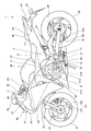
- FIG. 1 is a left side view of a motorcycle according to an embodiment of the present invention.
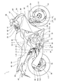
- Fig. 2 is a right side view of the motorcycle. It is a figure which shows a vehicle body frame with a damping
- FIG. 1 is a left side view of a motorcycle 1 according to an embodiment of the present invention.
- 2 is a right side view of the motorcycle 1
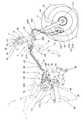
- FIG. 3 is a diagram showing the vehicle body frame 2 together with the braking structure.
- a vehicle body frame 2 of the motorcycle 1 has a head pipe 11 disposed at the front end thereof and a pair of left and right main frames 12 extending rearward and downward from the upper left and right of the head pipe 11.
- a pair of left and right down frames 13 (see FIG.
- the vehicle body frame 2 extends between the upper portion of the pivot plate 15 to the rear upper side, and is connected to the left and right pair of reinforcing rear frames 17 (see FIG. 3) respectively connected to the rear frames 14 And a plurality of reinforcing frames 18 (see FIG. 3) to be cross-linked.
- the head pipe 11 supports a steering device 20 that steers the front wheel 19.
- the steering device 20 includes a steering stem 21 rotatably supported by the head pipe 11, a lower bridge member (also referred to as an under bridge) 22 fixed to a lower portion of the steering stem 21,
- the driver is provided with a fixed upper bridge member (also referred to as a top bridge) 23, a pair of left and right front forks 24 supported by the upper and lower bridge members 22 and 23, and a handle 25 attached to the upper bridge member 23.
- the front wheel 19 supported at the lower end of the front fork 24 is steered to the left and right by the steering wheel operation.
- the main frame 12 is a frame for supporting an internal combustion engine 31, a fuel tank 32 and peripheral parts of these main parts.
- the engine 31 is below the main frame 12, behind the down frame 13 and in front of the pivot plate 15. Supported by The engine 31 is thereby suspended at the lower front and rear center of the vehicle body frame 2.
- an engine output shaft 31B is provided at the left rear of the crankcase 31A of the engine 31.
- the engine output shaft 31B and the rear wheel 26 are connected to be able to transmit power through a drive chain (hereinafter referred to as a chain) 34, and the power of the engine 31 is transmitted to the rear wheel 26 through the chain 34. .
- a drive chain hereinafter referred to as a chain
- a pivot shaft 36 pivotally supporting the front end portions of the pair of left and right swing arms 35 is penetrated and supported by the upper and lower intermediate portions of the pivot plate 15.
- the pivot shaft 36 is disposed parallel to the vehicle width direction, and supports the swing arm 35 so as to be vertically pivotable about the pivot shaft 36.
- a single rear cushion 37 (see FIG. 1) is interposed between the swing arm 35 and the vehicle body frame 2.
- the pair of left and right rear frames 14 supports the passenger seat 41 on which the driver sits and the passenger seat 42 on which the same passenger sits with a gap in front and rear, and a rear side rear fender 43 behind the passenger seat 42 And rear lights 44 etc.
- a fuel tank 32 is disposed in front of the driver's seat 41, and an engine 31 is disposed below the fuel tank 32.
- the main frames (head pipe 11, main frame 12, down frame 13, rear frame 14, reinforcement rear frame 17) other than pivot plate 15 of vehicle body frame 2 are formed of a metal pipe made of a metal material such as steel.
- the pivot plate 15 is formed of a plate-like member made of a metal material.
- the motorcycle 1 includes a vehicle body cowl 60 (also referred to as a vehicle body cover) that covers the vehicle body.
- the body cowl 60 is configured as a full cowling type that covers substantially the entire body, and includes a front cowl 61 covering the front of the body and a pair of left and right side cowls 62 continuously connected to the front cowl 61 to cover the left and right of the body.
- a lower cowl 63 covering the lower side of the vehicle body and a pair of left and right rear cowls 64 covering the rear of the vehicle body are provided.
- the front cowl 61 is provided in front of the head pipe 11 and the main frame 12, and a headlight 66, a windscreen 67, a pair of left and right rearview mirrors 68 and the like are attached.
- the side cowl 62 is connected to the front cowl 61 and covers the front left and right of the vehicle body frame 2 and the front and rear of the engine 31 (cylinder portion 31C).
- Roacowl 63 is connected to the lower part of the side cowl 62 and covers the lower part of the crankcase 31A of the engine 31.
- An engine intake system is disposed rearward of the cylinder portion 31C of the engine 31.
- a muffler 69 is disposed on the rear lower side of the vehicle body frame 2 and on the side (right side) of the rear wheel 26, and between the front end of the muffler 69 and the cylinder portion 31C of the engine 31.
- An exhaust pipe 70 is connected, and the exhaust pipe 70 and the muffler 69 constitute an engine exhaust system.
- reference numeral 71 denotes a pair of left and right main steps where the driver places his / her foot
- reference numeral 72 denotes a front fender covering the upper side of the front wheel 19.
- FIG. 4 is a view of the braking device 80 as viewed from the upper side of the vehicle body along with the peripheral configuration
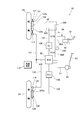
- FIG. 5 is a view showing a circuit configuration of the braking device 80.
- the braking device 80 includes a brake lever 81 as a brake operating element attached to the handle 25 and a lever-side master that generates a brake fluid pressure (hydraulic pressure) by operation of the brake lever 81.
- the braking device 80 connects a pressure control valve (hereinafter referred to as PCV) 106 provided in the middle of the pipe 103 connected to the rear wheel braking device 102, and the front wheel braking device 101 and the ABS modulator 88 respectively.
- PCV pressure control valve
- Delay valve (DV) 108 provided in the middle of the pipe 107 as the output brake pipe, a front wheel speed sensor 113 for detecting the rotational speed (wheel speed) of the front wheel 19, and the rotational speed of the rear wheel 26 (wheel speed And a controller 118 that controls the ABS modulator 88 based on the signals from the wheel speed sensors 113 and 116.
- reference numeral 171 denotes a reserve tank 171 of the pedal side master cylinder 84
- reference numeral 172 denotes a pipe connecting the reserve tank 171 and the pedal side master cylinder 84
- reference numeral 175 denotes the reserve tank 171.
- the ABS modulator 88 controls the braking force of each of the brake devices 101 and 102 by controlling the brake fluid pressure of the front wheel brake device 101 and the rear wheel brake device 102 under the control of the control device 118, and controls the front wheels 19 and It functions as a braking force control device that prevents the rear wheel 26 from locking.
- the ABS modulator 88 has a substantially rectangular box shape, and is attached to the vehicle body frame 2 via support stays 88A provided in front of and on the left and right of the ABS modulator 88, It is disposed in front of the front rear fender 151 covering the front upper portion of the rear wheel 26 and behind the rear cushion 37 and under the passenger seat 41 and above the swing arm 35.
- the ABS modulator 88 includes an electric motor, a pump driven by the electric motor, a plurality of brake fluid passages connected to the pump, and a plurality of solenoid valves provided in the middle of the brake fluid passages. It is a heavy part having a relatively heavy weight. By arranging the heavy parts at the positions, the mass of the motorcycle 1 can be concentrated as compared with the case where the heavy parts are disposed at the front end and the rear end of the motorcycle 1.
- the front wheel brake device 101 is a hydraulic disc brake that constitutes a hydraulic braking device, and as shown in FIG. 1, is mounted on the side (right side) of the front wheel 19 and rotates together with the brake disc 121. And a brake caliper 122 for holding the brake disc 121 and braking.
- the motorcycle 1 is configured in a single disc type in which a hydraulic disc brake is provided only on one side (right side) of the front wheel 19.
- cylinders 122a and 122b are formed, in which pistons for pressing the brake pads against the brake disc 121 are movably inserted, and pipes 92 and 109 are formed in each of the cylinders 122a and 122b. Is connected.
- a flexible brake hose such as a rubber hose is used so that the steering of the front wheel 19 can be followed.
- Pipings 92 and 109 of these brake hoses are metal pipes wired on the vehicle body frame 2 side via front wheel brake output side joints (hereinafter referred to as FB output side joints) 200 provided on the vehicle body frame 2 side. It is connected to a certain pipe 91, 107.
- the rear wheel brake device 102 is a hydraulic disc brake that constitutes a hydraulic braking device, and is attached to the side (right side) of the rear wheel 26 and rotates integrally with the rear wheel 26;
- a brake caliper 125 is provided to hold the disc 124 for braking, and a single cylinder 125a is formed in the brake caliper 125.
- a piston for pressing the brake pad against the brake disc 124 is movably inserted.
- a flexible brake hose such as a rubber hose is used so as to follow up and down movement of the rear wheel.
- the PCV 106 functions as an interlocking brake control device for controlling the brake fluid pressure of the pipe 103 connected to the rear wheel brake device 102.
- the brake pedal 83 is operated by the PCV 106
- the rear wheel brake device 102 is operated.
- the braking force is adjusted, and the front wheel brake device 101 is operated in conjunction with the operation of the rear wheel brake device 102 to execute the front and rear wheel interlock brake.
- the delay valve 108 functions as a front wheel brake control device for adjusting the operation timing of the front wheel brake device 101.
- the front wheel brake control device performs front and rear wheel interlock brakes, the brake for the front wheel brake device 101 is performed.
- the supply of hydraulic pressure is delayed more than the rear wheel brake device 102 side.
- the front wheel speed sensor 113 is a sensor that detects the front wheel speed using a pulsar ring 114 (see FIG. 2) attached to the side (right side) of the front wheel 19, and a wire 131 extending from the front wheel speed sensor 113. Is connected to the controller 118 and the ABS modulator 88, and the output signal of the sensor 113 is output to the controller 118 and the ABS modulator 88.
- the rear wheel speed sensor 116 is a sensor that detects a rear wheel speed using a pulsar ring 117 (see FIG. 2) attached to the side (right side) of the rear wheel 26.
- Control device 118 obtains front wheel speed and rear wheel speed based on the signals from front wheel speed sensor 113 and rear wheel speed sensor 116, and the front and rear wheels slip based on the difference between front wheel speed and rear wheel speed.
- the front wheel brake device 101 and the rear wheel brake device 102 are controlled so as not to occur.
- the pedal side master cylinder 84 when the brake pedal 83 is operated, the pedal side master cylinder 84 generates a brake fluid pressure according to the operation of the brake pedal, and the brake fluid pressure passes through the pipe 87. Then, it is supplied to the ABS modulator 88.
- the ABS modulator 88 operates the rear wheel brake device 102 by supplying the brake fluid pressure from the ABS modulator 88 to the pipe 103, and simultaneously applies the brake fluid pressure from the ABS modulator 88 to the flexible brake.
- the brake fluid pressure is supplied to the cylinder 122 b of the front wheel brake device 101 via the delay valve 108 by supplying to the pipe 107 which is a hose, and the front wheel brake device 101 is operated.
- the front-rear interlocking brake that simultaneously operates the front wheel brake device 101 and the rear wheel brake device 102 is performed.
- the controller 118 monitors the front wheel speed and the rear wheel speed, and controls the brake hydraulic pressure from the ABS modulator 88 so that the front wheel 19 and the rear wheel 26 do not lock.
- the lever side master cylinder 82 when the brake lever 81 is operated, the lever side master cylinder 82 generates a brake fluid pressure corresponding to the operation of the brake lever 81, and this brake fluid pressure is supplied to the ABS modulator 88 via the pipe 86. Be done.
- the ABS modulator 88 supplies the brake fluid pressure from the ABS modulator 88 to the pipe 91, which is a metal pipe, to thereby apply the brake fluid pressure to the front wheel brake device 101 via the pipe 92, which is a flexible brake hose. Is supplied to the cylinder 122a, and the front wheel brake device 101 is operated.
- the ABS modulator 88 When the front-rear interlocking brake is performed when the brake lever 81 is operated, the ABS modulator 88 further supplies the brake fluid pressure adjusted by the ABS modulator 88 to the pipe 103 to operate the rear wheel brake device 102. During this braking, the control device 118 monitors the front wheel speed and the rear wheel speed, and controls the brake hydraulic pressure from the ABS modulator 88 so that the front wheel 19 and the rear wheel 26 do not lock.
- the ABS modulator 88 of the motorcycle 1 has a body frame 2 by inserting a not-shown mount rubber made of an elastic member between a plurality of support stays 88A and the body frame 2 in order to prevent vibration. Is mounted floating. For this reason, the vibration transmission between the vehicle body frame 2 and the ABS modulator 88 is suppressed, and it is possible to make it difficult to transmit the vibration on the vehicle body frame 2 side to the ABS modulator.
- the floating mount structure of the ABS modulator 88 can be widely applied to the conventional floating mount structure.
- the front wheel side braking structure is configured as follows.
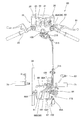
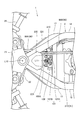
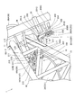
- FIG. 6 is a view of the front portion of the vehicle body as viewed from above with the brake piping
- FIG. 7 is a view as viewed from below
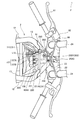
- FIG. 8 is a view as viewed from the front
- FIG. FIG. 10 is a view seen from the left side.
- reference numeral L10 denotes an axis of the head pipe 11.
- the engine 31 of the motorcycle 1 is water-cooled, and as shown in FIG. 8, a radiator 45 for cooling engine cooling water is located behind and below the head pipe and in front of the pair of left and right down frames 13.
- Prepare for The brake lever 81 operated by the driver is provided on the right side of the handle 25 as shown in FIGS. 4 and 7, and a lever-side master cylinder 82 is provided at the base end of the brake lever 81.
- the lever-side master cylinder A pipe 86 which is an input brake pipe, extends from 82.
- the pipe 86 includes a first pipe 86A fixed to the brake lever 81 and a second pipe 86B connected to the ABS modulator 88.
- a rubber hose is attached to the first pipe 86A.
- Etc. and a metal pipe is used for the second pipe 86B, and the first pipe 86A and the second pipe 86B are provided on the front side of the vehicle front side with respect to the front wheel brake input side joint portion. (Hereinafter, it is called FB input side joint part) 210 (refer FIG. 9) and is connected.
- the FB input side joint portion 210 is a fastening member (fastened in this configuration) to the stay portion 211 provided on the foremost reinforcing frame 18A of the plurality of reinforcing frames 18 bridging the main frame 12 and the down frame 13.
- the first pipe 86A is connected to the front side of the FB input side joint portion 210, and the second pipe 86B is connected to the rear side.
- the second pipe 86B which is a metal pipe, extends rearward and downward along the widthwise inner side of the right main frame 12 and is connected to the ABS modulator 88, as shown in FIGS.
- pipes 91 and 107 which are brake pipes for front wheel output and are metal pipes, extend forward, and these pipes 91 and 107 are in the vehicle width direction of the main frame 12 on the right side. It extends frontward and upward along the inside.
- the two pipes 91 and 107, which are the front-wheel output brake pipes, and the single pipe 86, which is the front-wheel input brake pipe are the vehicle width of the main frame 12 on the same side (right side) in the vehicle width direction. They are arranged centrally inside the direction, and arranged compactly (see FIG. 3).
- the FB output side joint portion 200 is provided in the vicinity of the head pipe 11 at the front end of the vehicle body frame 2, and the pipes 91 and 107 which are metal pipes have flexibility via the FB output side joint portion 200. It is connected to piping 92, 109 which consists of a brake hose which it has.
- the pipes 91 and 107 of the metal pipe are mainly made of the vehicle body frame 2 (see FIGS. 3 and 4) between the ABS modulator 88 and the FB output side joint portion 200 by the locking member 215 (see FIGS. 3 and 4). It is locked to the right main frame 12). Since the resin material is more flexible than the metal material used for the metal pipe, the locking member 215 absorbs to some extent the relative displacement between the vehicle body frame 2 and the metal pipe (pipes 91 and 107). It is possible to reduce the load on the metal pipe.
- the pipe 107 is provided with the delay valve 108 in the middle thereof, the first pipe 107A, which is a metal pipe connecting between the ABS modulator 88 and the delay valve 108, the delay valve 108 and the FB output side joint portion 200 And a second pipe 107B which is a metal pipe connecting the two.
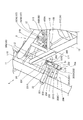
- the delay valve 108 is supported by a support stay 221 (see FIG. 7) provided on the vehicle body frame 2 side. As shown in FIG. 7, the support stay 221 is surrounded by the cross member 220 extending in the vehicle width direction so as to connect the front portions of the left and right down frames 13, a pair of left and right down frames 13 and the head pipe 11.
- a reinforcing plate member 231 joined so as to cover the triangular region to be formed, and is formed in an arm shape extending rearward of the cross member 220 from the center in the vehicle width direction. Then, a support plate portion 108A (see FIG. 6) provided on the delay valve 108 is placed on the upper surface of the support stay 221, and a fastening member (fastening bolt in this configuration) 223 is passed from above the support plate portion 108A.
- the delay valve 108 is fixed to the vehicle body frame 2 by fastening to the support stay 221.
- the axis L11 of the fastening member 223 is parallel to the axis L10 of the head pipe 11, and as shown in FIGS. 6 and 7, the head pipe 11, as seen in the axial direction of the head pipe 11. It passes between the vehicle body frames 2 apart from the pair of left and right main frames 12 and the steering device 20 and the like.
- the axis L11 of the fastening member 223 coincides with the fastening axis of the fastening member 223, the access to the fastening member 223 becomes easy in the axial direction of the head pipe 11, and the attachment and detachment of the delay valve 108 is facilitated. It will be possible to do.
- the axial direction of the head pipe 11 coincides with the expansion and contraction direction of the front fork 24, so By means of this fastening member 223, the fixing strength of the delay valve 108 can be efficiently secured.
- the pair of left and right down frames 13 constitute left and right rear extension parts extending left and right from the head pipe 11, and the pair of left and right down frames 13 and the head pipe 11
- a plate-like reinforcing plate member 231 for improving the connection rigidity between the down frame 13 and the head pipe 11 is joined by welding to the triangular region surrounded by the above.
- the reinforcing plate member 231 is formed of a metal material such as steel and extends rearward and downward in a side view, and the lower surface 231A is a surface extending in a direction perpendicular to the axis L10 of the head pipe 11. There is.
- a joint support stay 250 for supporting the FB output side joint portion 200 is attached to the lower surface 231A of the reinforcing plate member 231.
- the pair of left and right main frames 12 are also left and right rear extension parts extending rearward from the head pipe to the left and right, and the pair of left and right main frames 12 and head pipes 11
- a plate-like reinforcing plate member 235 for improving the connection rigidity between the main frame 12 and the head pipe 11 is also joined by welding to the triangular region surrounded by the above.
- the reinforcing plate member 235 is positioned on the front upper side of the delay valve 108 and the FB input side joint portion 210, and extends from the upper side of the second pipe 107B and the first pipe 86A extending forward from the delay valve 108 and the FB input side joint portion 210. It can be covered and protected.
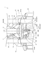
- FIG. 11 shows a longitudinal cross section of the joint support stay 250 together with its peripheral configuration.
- the joint support stay 250 is formed by bending a metal plate member, and is fixed to the lower surface 231A of the reinforcing plate member 231 via the mount rubber 260, and from the front end of the fixed plate portion 251.
- a front plate portion 252 bent substantially vertically and extending forward and downward to form a front plate, and a lower plate portion 253 bent substantially vertically backward from the lower end of the front plate portion 252 to form a lower plate;
- a side plate portion 254 is integrally formed with a side plate portion that is bent backward from the side edge of the front plate portion 252 at one end side (right side) of the vehicle width direction to form a side plate.
- the fixed plate portion 251 constitutes the upper plate portion of the joint support stay 250, and the fixed plate portion 251 is provided with a single opening 251A penetrating in the vertical direction, and the opening 251A is elastic.
- a cylindrical mount rubber 260 functioning as a member is held.
- the mount rubber 260 is formed of a plurality of elastic washers (two rubber washers in the present configuration) 261 formed of an elastic material, and a rigid material such as metal or resin, and a cylinder inserted into the hole of the elastic washer 261 And an annular collar 262.
- the cylindrical collar 262 includes a cylindrical portion 262A inserted through the hole of the elastic washer 261 and the opening 251A of the fixed plate 251, and a large-diameter flange portion 262B provided on one end side of the cylindrical portion 262A.
- the cylindrical portion 262A is formed to have a length equal to or shorter than the total thickness when all the elastic washers 261 and the fixing plate portion 251 are stacked, and a length that allows elastic deformation of the elastic washer 261.
- the flange portion 262B is formed to have an outer diameter such that the plurality of elastic washers 261 passed through the cylindrical portion 262A and the fixing plate portion 251 do not come off.
- the elastic washer 261 and the fixing plate portion 251 are inserted into the cylindrical portion 262A of the cylindrical collar 262 so that the fixing plate portion 251 of the joint support stay 250 is laminated between the elastic washers 261.
- a fastening member (a fastening bolt in the present configuration) 265 is inserted from the side of the flange portion 262B of the cylindrical collar 262, and is fastened to the female screw hole 231B provided in the reinforcing plate member 231.
- the fixing plate portion 251 is fixed to the reinforcing plate member 231 via the elastic washer 261, that is, the FB output side joint portion 200 is floatingly mounted on the vehicle body frame 2.
- the fixing plate portion 251 is disposed between the elastic washers 261, the fixing plate portion 251, that is, the joint support stay 250 is a fastening member relative to the vehicle body frame 2 by the elastic deformation of each elastic washer 261. It can be relatively moved in the reciprocating direction along the axis L12 of the H.265.
- the number of elastic washers 261 is not limited to two, and may be changed according to various conditions such as the target relative movement amount and the thickness per elastic washer 261.
- the fixing plate portion 251 is fixed to the reinforcing plate member 231 via the rigid cylindrical collar 262 and the fastening member 265, so in this direction
- the support stay 250 is rigidly mounted, and relative movement of the joint support stay 250 in this direction is restricted.
- a pair of upper and lower joint portions 201 and 202 constituting the FB output side joint portion 200 is fixed to the lower plate portion 253. More specifically, the upper and lower pair of joint parts 201 and 202 are single-sided input provided on one side (right side) of the rectangular parallelepiped joint part bodies 201A and 202A and the joint part bodies 201A and 202A in the vehicle width direction.
- the hole portion 201D of the joint portion 201 is formed in a female screw hole, and the hole portion 202D of the lower joint portion 202 is formed in a simple through hole.
- a single fastening member (in the present configuration, a fastening bolt) 266 is provided in the hole 202D of the lower joint portion 202 from the lower side and the through hole 253A provided in the lower plate portion 253.
- the lower plate portion 253 is sandwiched between the upper and lower joint portions 201 and 202 by sequentially passing through and fastening to the hole portion 201D of the upper joint portion 201, and the upper and lower joint portions 201 and 202 are jointed with a simple structure. It can be fixed to the support stay 250.
- reference numeral 271 is a locking member mounted across the front surfaces of the joint portions 201 and 202 in order to lock the joint portions 201 and 202.
- a second pipe 107B which is a metal pipe, is connected to the side input pipe portion 201B of the upper joint portion 201, and a pipe 109, which is a flexible brake hose, is connected to the front output pipe portion 201C.
- the front output pipe portion 201C extends forward from the joint portion main body 201A so as to be orthogonal to the axis L10 of the head pipe 11, as shown in FIG. 8, so the pipe 109 connected to the front output pipe portion 201C is It can be disposed in a direction, and can be gently bent and connected toward the front wheel brake device 101 (brake caliper 122) located in front of the joint portion 201.
- a pipe 91 which is a metal pipe, is connected to the side input pipe portion 202B of the lower joint portion 202
- a pipe 92 which is a flexible brake hose, is connected to the front output pipe portion 202C.
- Ru The front output pipe portion 202C is also connected to the front output pipe portion 202C because it extends forward so as to be orthogonal to the axis L10 of the head pipe 11 as in the case of the front output pipe portion 201C as shown in FIG. It is possible to gently bend and connect the connecting pipe 92 toward the front wheel brake device 101 (brake caliper 122) located in front of the joint portion 202.
- the front and rear front output pipe portions 201C and 202C are provided near the center line in the vehicle width direction that coincides with the axis L10 of the head pipe 11 in front view.
- the separation distances from the front output pipe portions 201C and 202C to the front wheel brake device 101 provided on the front wheel 19 can be made substantially the same on the left and right, and the flexible brake hose It becomes easy to arrange the piping 109, 92 which is.
- the side plate portion 254 extends between the second pipe 107B and the pipe 91, which are metal pipes connected to the FB output side joint portion 200, and the head pipe 11, and the joint support stay
- the rigidity of the support stay 250 itself is improved by making L-shaped 250 in a horizontal cross section.
- the fastening member 265 for fixing the joint support stay 250 to the vehicle body frame 2 has an axis L12 which coincides with the fastening axis and is parallel to the axis L10 of the head pipe 11. In the axial direction, as shown in FIG. 7, access to the fastening member 265 is easy.
- the axis L13 coinciding with the fastening axis is the axis L10 of the head pipe 11 Since they are formed parallel to each other and at positions separated longitudinally and laterally with the axis L12 of the fastening member 265, access to the fastening member 266 is also easy. Therefore, various operations such as attaching and detaching operations of the FB output side joint unit 200 can be easily performed.
- the axial direction of the head pipe 11 coincides with the expansion and contraction direction of the front fork 24.
- the fastening strength of the FB output side joint portion 200 can be efficiently secured by the fastening members 265 and 266.
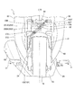
- FIG. 12 is a view of the brake hose (pipes 109 and 92) viewed from the front of the vehicle body.
- the pipes 109, 92 extend forward toward the left side opposite to the brake caliper 122 in the vehicle width direction, and then inward in the vehicle width direction with respect to the left front fork 24. Is curved to form a convex curved portion 109T, 92T forward toward the lower right, and is drawn rearward through the inner side in the vehicle width direction of the front fork 24 on the right, and then curved downward to form a brake It is connected to the caliper 122.
- the pipes 109 and 92 are fixed to a support stay (not shown) fixed to the front fork 24 via a pipe gripping member (for example, a grommet) 272 at a location passing through the inside of the right front fork 24. Be done. For this reason, when the front fork 24 expands and contracts in the vertical direction with respect to the vehicle body, the curved portions 109T and 92T convex in the forward direction deform in accordance with the expansion and contraction.
- the curved portions 109T and 92T have a convex shape in the forward direction and are shaken to the right after being shaken to the left from the FB output side joint portion 200 and fixed on the right side of the vehicle body, so that the curved portions 109T and 92T are
- the pipe length can be efficiently secured, and the expansion and contraction can be easily made to follow.
- the FB output side joint portion 200 is floatingly mounted on the vehicle body frame 2 via the mount rubber 260 which is an elastic member, it is connected to the FB output side joint portion 200
- the displacement between the second pipe 107B and the pipe 91, which are metal pipes, and the pipes 109 and 92, which are flexible brake hoses, can be absorbed by the elastic deformation of the mount rubber 260.
- the load acting on the output side joint unit 200 can be reduced.
- both the ABS modulator 88 and the FB output side joint portion 200 are floatingly mounted from the vehicle body frame 2, and the entire braking device 80 is vibrated by the vehicle body frame 2.
- the load acting on each part of the braking device 80 can be efficiently reduced. If the load acting on each part of the braking device 80 can be reduced as described above, weight reduction and cost reduction can be achieved accordingly.
- the FB output side joint unit 200 connects a plurality of pairs (two pairs in the present embodiment) of metal pipes (the second pipe 107B and the pipe 91) and the brake hose (the pipes 109 and 92). Since the single joint support stay 250 is held and the single joint support rubber 250 is provided between the joint support stay 250 and the vehicle body frame 2, the support stay is formed of a plurality of pairs of metal pipes and brake hoses. It is possible to share the mount rubber and reduce the number of parts.
- the FB output side joint portion 200 is fixed to the vehicle body frame 2 by the fastening member 265 extending in parallel with the axis L10 extending in the vertical direction of the head pipe 11, and the mount rubber 260 is the FB output side joint portion 200.
- the mount rubber 260 is the FB output side joint portion 200.
- the joint portion 200 allows relative displacement of the vehicle body frame 2 in the vertical direction of the vehicle by the mount rubber 260, and changes the distance between the FB output side joint portion 200 and the steering device 20 in the plane direction (front, rear, left and right).
- the braking device 80 can be separated from the vibration of the vehicle body frame 2 in the vertical direction, and when the steering device 20 is steered, the brake hose (pipe 109, The position of the FB output side joint portion 200 which is the base point of 92) does not change, and the brake hose length can be set short while appropriately separating the brake hose and the steering device 20.
- the brake hose length can be set short by reducing the interference with the front fork 24.
- a plate-like reinforcing plate member 231 is provided in a triangular area surrounded by the head pipe 11 and the down frame 13 which is a left rear extension extending left and right from the head pipe 11. Since the FB output side joint unit 200 is fixed to the reinforcing plate member 231, the FB output side joint unit 200 can be fixed in the vicinity of the head pipe 11 without increasing the number of parts.
- the brake hoses (pipes 109 and 92) connected to the FB output side joint portion 200 extend in the direction orthogonal to the axis L10 of the head pipe 11, the base points of the FB output side joint portion 200 and the brake hose It can be disposed as close as possible to the head pipe 11, and the entire vehicle can be made compact.
- the pipes 91 and 107 of the metal pipe are locked to the vehicle body frame 2 by the locking member 215 made of resin, the vehicle body frame 2 is locked by the locking member 215 having more flexibility than the metal pipe. It is possible to absorb the relative displacement between the and the metal pipe to some extent and reduce the load on the metal pipe. Therefore, it is possible to reduce the weight of the metal pipe by reducing the thickness of the metal pipe.
- the delay valve 108 for adjusting the operation timing of the front wheel brake device 101 since the delay valve 108 for adjusting the operation timing of the front wheel brake device 101 is provided, and the delay valve 108 is fixed to the arm-like support stay 221 extending rearward from the reinforcing plate member 231, reinforcement is provided.
- the delay valve 108 can be fixed using the plate member 231.
- the axis L11 of the fastening member 223 for fixing the delay valve 108 to the support stay 221 passes between the vehicle body frames 2 in the axial direction view of the head pipe 11, access to the fastening member 223 becomes easy. It becomes possible to easily carry out the mounting and demounting operation of the valve 108, the assembling property is excellent, and the productivity is improved.
- the embodiment described above is merely an aspect of the present invention, and can be arbitrarily modified and applied without departing from the spirit of the present invention.
- the present invention is not limited thereto, and a double disc brake type in which the front wheel brake device 101 is disposed on the left and right It may apply to
- the present invention is not limited to this, and the present invention may be widely applied to a braking device of a saddle-ride type vehicle. it can.
- ddle-ride type vehicle includes all vehicles that ride on the vehicle body, and is not limited to motorcycles (including motorbikes), but also three-wheeled vehicles and four-wheeled vehicles classified as ATV (rough terrain vehicles) It is a vehicle that contains
Abstract
Priority Applications (5)
| Application Number | Priority Date | Filing Date | Title |
|---|---|---|---|
| US13/635,848 US8651213B2 (en) | 2010-03-19 | 2011-02-28 | Brake device for saddled vehicle |
| KR1020127026629A KR101479827B1 (ko) | 2010-03-19 | 2011-02-28 | 안승형 차량의 제동 장치 |
| ES11755824.7T ES2593637T3 (es) | 2010-03-19 | 2011-02-28 | Dispositivo de freno para vehículo de montar a horcajadas |
| BR112012023674-1A BR112012023674B1 (pt) | 2010-03-19 | 2011-02-28 | Dispositivo de frenagem de veículo do tipo conduzido na posição montada |
| EP11755824.7A EP2548792B1 (fr) | 2010-03-19 | 2011-02-28 | Dispositif de frein pour un véhicule à selle |
Applications Claiming Priority (2)
| Application Number | Priority Date | Filing Date | Title |
|---|---|---|---|
| JP2010064198A JP5478307B2 (ja) | 2010-03-19 | 2010-03-19 | 鞍乗り型車両の制動装置 |
| JP2010-064198 | 2010-03-19 |
Publications (1)
| Publication Number | Publication Date |
|---|---|
| WO2011114631A1 true WO2011114631A1 (fr) | 2011-09-22 |
Family
ID=44648747
Family Applications (1)
| Application Number | Title | Priority Date | Filing Date |
|---|---|---|---|
| PCT/JP2011/001146 WO2011114631A1 (fr) | 2010-03-19 | 2011-02-28 | Dispositif de frein pour un véhicule à selle |
Country Status (6)
| Country | Link |
|---|---|
| US (1) | US8651213B2 (fr) |
| EP (1) | EP2548792B1 (fr) |
| JP (1) | JP5478307B2 (fr) |
| KR (1) | KR101479827B1 (fr) |
| ES (1) | ES2593637T3 (fr) |
| WO (1) | WO2011114631A1 (fr) |
Cited By (2)
| Publication number | Priority date | Publication date | Assignee | Title |
|---|---|---|---|---|
| WO2020031455A1 (fr) * | 2018-08-09 | 2020-02-13 | 本田技研工業株式会社 | Véhicule de type à selle |
| EP4180309A1 (fr) * | 2021-11-12 | 2023-05-17 | TVS Motor Company Limited | Véhicule de type à selle |
Families Citing this family (31)
| Publication number | Priority date | Publication date | Assignee | Title |
|---|---|---|---|---|
| JP2014015176A (ja) * | 2012-07-11 | 2014-01-30 | Yamaha Motor Co Ltd | 鞍乗型車両用連動ブレーキ装置及び鞍乗型車両 |
| JP6151896B2 (ja) * | 2012-08-28 | 2017-06-21 | 本田技研工業株式会社 | 鞍乗り型車両の配索構造 |
| JP2014080057A (ja) * | 2012-10-15 | 2014-05-08 | Kawasaki Heavy Ind Ltd | 自動二輪車のリヤブレーキ装置 |
| JP6023576B2 (ja) * | 2012-12-17 | 2016-11-09 | 川崎重工業株式会社 | 自動二輪車 |
| JP6122732B2 (ja) * | 2013-08-09 | 2017-04-26 | 本田技研工業株式会社 | 鞍乗型車両 |
| JP6165012B2 (ja) * | 2013-09-30 | 2017-07-19 | 本田技研工業株式会社 | 鞍乗り型車両の連動ブレーキ部品配置構造 |
| US9855987B2 (en) * | 2013-11-07 | 2018-01-02 | Kawasaki Jukogyo Kabushiki Kaisha | Vehicle body frame structure of straddle-type vehicle |
| US10389992B2 (en) * | 2014-08-05 | 2019-08-20 | Utherverse Digital Inc. | Immersive display and method of operating immersive display for real-world object alert |
| CN105460136A (zh) * | 2014-09-10 | 2016-04-06 | 光阳工业股份有限公司 | 摩托车倾倒感知器的配置 |
| CN104443221A (zh) * | 2014-10-29 | 2015-03-25 | 力帆实业(集团)股份有限公司 | 可更换制动踏板的后制动踏板组合 |
| KR102275712B1 (ko) * | 2014-10-31 | 2021-07-09 | 삼성전자주식회사 | 렌더링 방법, 렌더링 장치 및 전자 장치 |
| DE102015220286A1 (de) * | 2015-10-19 | 2017-04-20 | Robert Bosch Gmbh | Elektronisches Bremsdruckregelsystem |
| JP6234486B2 (ja) * | 2016-01-27 | 2017-11-22 | 本田技研工業株式会社 | 自動二輪車 |
| JP6318437B2 (ja) * | 2016-01-27 | 2018-05-09 | 本田技研工業株式会社 | 鞍乗り型車両 |
| EP3225526B1 (fr) | 2016-03-28 | 2019-10-23 | Honda Motor Co., Ltd. | Structure de support de câble de véhicule de type à selle |
| JP6866091B2 (ja) * | 2016-09-13 | 2021-04-28 | 川崎重工業株式会社 | 自動二輪車 |
| JP6404308B2 (ja) | 2016-12-27 | 2018-10-10 | 本田技研工業株式会社 | 鞍乗型車両 |
| JP2020032734A (ja) * | 2016-12-28 | 2020-03-05 | ヤマハ発動機株式会社 | 鞍乗型車両 |
| US10723334B2 (en) | 2017-03-28 | 2020-07-28 | Polaris Industries Inc. | Anti-lock brake system for all-terrain vehicle |
| WO2019049467A1 (fr) * | 2017-09-07 | 2019-03-14 | 本田技研工業株式会社 | Structure avant de véhicule du type à selle |
| DE112018005483B4 (de) | 2017-09-28 | 2023-11-30 | Honda Motor Co., Ltd. | Bremsleitungsstruktur für Sattelfahrzeuge |
| JP6674427B2 (ja) * | 2017-09-28 | 2020-04-01 | 本田技研工業株式会社 | 鞍乗り型車両 |
| JP2019084965A (ja) * | 2017-11-07 | 2019-06-06 | ヤマハ発動機株式会社 | 鞍乗型車両 |
| WO2019104119A1 (fr) | 2017-11-22 | 2019-05-31 | Polaris Industries Inc. | Système de freinage antiblocage commutable pour véhicule utilitaire |
| JP6642837B2 (ja) * | 2017-12-28 | 2020-02-12 | 本田技研工業株式会社 | 鞍乗り型車両のabs配置構造 |
| US11618422B2 (en) | 2018-11-14 | 2023-04-04 | Polaris Industries Inc. | Operating modes using a braking system for an all terrain vehicle |
| WO2019213417A1 (fr) | 2018-05-02 | 2019-11-07 | Polaris Industries Inc. | Modes de fonctionnement utilisant un système de freinage pour un véhicule tout terrain |
| JP7163392B2 (ja) * | 2018-08-09 | 2022-10-31 | 本田技研工業株式会社 | 鞍乗型車両 |
| JP6806745B2 (ja) * | 2018-08-30 | 2021-01-06 | 本田技研工業株式会社 | 鞍乗り型車両の車体フレーム構造 |
| JP7198696B2 (ja) | 2019-03-19 | 2023-01-04 | 本田技研工業株式会社 | 自動二輪車 |
| JP6904999B2 (ja) * | 2019-03-29 | 2021-07-21 | 本田技研工業株式会社 | 鞍乗り型車両 |
Citations (5)
| Publication number | Priority date | Publication date | Assignee | Title |
|---|---|---|---|---|
| JP2007076555A (ja) * | 2005-09-15 | 2007-03-29 | Kawasaki Heavy Ind Ltd | 自動二輪車 |
| JP2007223521A (ja) * | 2006-02-24 | 2007-09-06 | Honda Motor Co Ltd | ブレーキ支持構造 |
| JP2009234533A (ja) | 2008-03-28 | 2009-10-15 | Honda Motor Co Ltd | 自動二輪車 |
| JP2009241801A (ja) * | 2008-03-31 | 2009-10-22 | Honda Motor Co Ltd | 自動二輪車用ブレーキ装置 |
| JP2010047232A (ja) * | 2008-08-25 | 2010-03-04 | Kawasaki Heavy Ind Ltd | 車両のブレーキ配管構造 |
Family Cites Families (6)
| Publication number | Priority date | Publication date | Assignee | Title |
|---|---|---|---|---|
| JP4184886B2 (ja) * | 2003-08-19 | 2008-11-19 | 本田技研工業株式会社 | 自動二輪車のabs油圧ユニット組立体の取付構造 |
| JP4306442B2 (ja) * | 2003-12-19 | 2009-08-05 | スズキ株式会社 | アンチロックブレーキ装置付自動二輪車 |
| JP4991464B2 (ja) * | 2006-12-27 | 2012-08-01 | 本田技研工業株式会社 | 自動二輪車 |
| JP4990208B2 (ja) * | 2008-03-31 | 2012-08-01 | 本田技研工業株式会社 | 自動二輪車用ブレーキ装置 |
| JP5025548B2 (ja) * | 2008-03-31 | 2012-09-12 | 本田技研工業株式会社 | 自動二輪車用ブレーキ装置 |
| JP5492491B2 (ja) * | 2009-08-10 | 2014-05-14 | 本田技研工業株式会社 | 自動二輪車 |
-
2010
- 2010-03-19 JP JP2010064198A patent/JP5478307B2/ja not_active Expired - Fee Related
-
2011
- 2011-02-28 ES ES11755824.7T patent/ES2593637T3/es active Active
- 2011-02-28 WO PCT/JP2011/001146 patent/WO2011114631A1/fr active Application Filing
- 2011-02-28 KR KR1020127026629A patent/KR101479827B1/ko active IP Right Grant
- 2011-02-28 EP EP11755824.7A patent/EP2548792B1/fr active Active
- 2011-02-28 US US13/635,848 patent/US8651213B2/en active Active
Patent Citations (5)
| Publication number | Priority date | Publication date | Assignee | Title |
|---|---|---|---|---|
| JP2007076555A (ja) * | 2005-09-15 | 2007-03-29 | Kawasaki Heavy Ind Ltd | 自動二輪車 |
| JP2007223521A (ja) * | 2006-02-24 | 2007-09-06 | Honda Motor Co Ltd | ブレーキ支持構造 |
| JP2009234533A (ja) | 2008-03-28 | 2009-10-15 | Honda Motor Co Ltd | 自動二輪車 |
| JP2009241801A (ja) * | 2008-03-31 | 2009-10-22 | Honda Motor Co Ltd | 自動二輪車用ブレーキ装置 |
| JP2010047232A (ja) * | 2008-08-25 | 2010-03-04 | Kawasaki Heavy Ind Ltd | 車両のブレーキ配管構造 |
Non-Patent Citations (1)
| Title |
|---|
| See also references of EP2548792A4 * |
Cited By (5)
| Publication number | Priority date | Publication date | Assignee | Title |
|---|---|---|---|---|
| WO2020031455A1 (fr) * | 2018-08-09 | 2020-02-13 | 本田技研工業株式会社 | Véhicule de type à selle |
| JPWO2020031455A1 (ja) * | 2018-08-09 | 2021-05-13 | 本田技研工業株式会社 | 鞍乗型車両 |
| JP7061670B2 (ja) | 2018-08-09 | 2022-04-28 | 本田技研工業株式会社 | 鞍乗型車両 |
| US11548584B2 (en) | 2018-08-09 | 2023-01-10 | Honda Motor Co., Ltd. | Saddle riding type vehicle |
| EP4180309A1 (fr) * | 2021-11-12 | 2023-05-17 | TVS Motor Company Limited | Véhicule de type à selle |
Also Published As
| Publication number | Publication date |
|---|---|
| US20130009378A1 (en) | 2013-01-10 |
| BR112012023674A2 (pt) | 2021-04-20 |
| KR20120140669A (ko) | 2012-12-31 |
| EP2548792B1 (fr) | 2016-09-14 |
| EP2548792A1 (fr) | 2013-01-23 |
| ES2593637T3 (es) | 2016-12-12 |
| JP2011195023A (ja) | 2011-10-06 |
| JP5478307B2 (ja) | 2014-04-23 |
| US8651213B2 (en) | 2014-02-18 |
| KR101479827B1 (ko) | 2015-01-06 |
| EP2548792A4 (fr) | 2015-01-28 |
Similar Documents
| Publication | Publication Date | Title |
|---|---|---|
| WO2011114631A1 (fr) | Dispositif de frein pour un véhicule à selle | |
| KR101260588B1 (ko) | 안장형 차량의 제동 장치 | |
| EP2604498B1 (fr) | Structure de conduite de frein de motocyclette | |
| US11493008B2 (en) | Straddle-type vehicle | |
| JP4825543B2 (ja) | ブレーキ支持構造 | |
| JP4937696B2 (ja) | クラッチ操作アシスト装置 | |
| US8235157B2 (en) | Step holder attachment structure for a saddle-type vehicle, and vehicle incorporating same | |
| JP2014080057A (ja) | 自動二輪車のリヤブレーキ装置 | |
| JP2009090887A (ja) | 鞍乗型車両 | |
| JP2005082024A (ja) | ブレーキホースの支持構造 | |
| EP3225526B1 (fr) | Structure de support de câble de véhicule de type à selle | |
| CN109720328B (zh) | 跨骑型车辆 | |
| JP6904999B2 (ja) | 鞍乗り型車両 | |
| JP2015085844A (ja) | 鞍乗型車両 | |
| CN110035948B (zh) | 一种带有同步制动系统的两轮车辆 | |
| US10780936B2 (en) | Straddle-type vehicle | |
| JP3157690U (ja) | 鞍乗型車両 | |
| JP7113797B2 (ja) | 鞍乗り型車両 | |
| JP7142657B2 (ja) | 鞍乗り型車両 | |
| EP4180309A1 (fr) | Véhicule de type à selle | |
| WO2020031455A1 (fr) | Véhicule de type à selle | |
| JP2019064297A (ja) | 鞍乗型車両のフレーム構造 |
Legal Events
| Date | Code | Title | Description |
|---|---|---|---|
| 121 | Ep: the epo has been informed by wipo that ep was designated in this application |
Ref document number: 11755824 Country of ref document: EP Kind code of ref document: A1 |
|
| WWE | Wipo information: entry into national phase |
Ref document number: 13635848 Country of ref document: US |
|
| NENP | Non-entry into the national phase |
Ref country code: DE |
|
| WWE | Wipo information: entry into national phase |
Ref document number: 1201004764 Country of ref document: TH |
|
| REEP | Request for entry into the european phase |
Ref document number: 2011755824 Country of ref document: EP |
|
| WWE | Wipo information: entry into national phase |
Ref document number: 2011755824 Country of ref document: EP |
|
| WWE | Wipo information: entry into national phase |
Ref document number: 8619/DELNP/2012 Country of ref document: IN |
|
| ENP | Entry into the national phase |
Ref document number: 20127026629 Country of ref document: KR Kind code of ref document: A |
|
| REG | Reference to national code |
Ref country code: BR Ref legal event code: B01A Ref document number: 112012023674 Country of ref document: BR |
|
| ENP | Entry into the national phase |
Ref document number: 112012023674 Country of ref document: BR Kind code of ref document: A2 Effective date: 20120919 |