WO2011108481A1 - スクアリリウム色素及びそれらの色素を用いた色素増感太陽電池、光電変換素子 - Google Patents
スクアリリウム色素及びそれらの色素を用いた色素増感太陽電池、光電変換素子 Download PDFInfo
- Publication number
- WO2011108481A1 WO2011108481A1 PCT/JP2011/054477 JP2011054477W WO2011108481A1 WO 2011108481 A1 WO2011108481 A1 WO 2011108481A1 JP 2011054477 W JP2011054477 W JP 2011054477W WO 2011108481 A1 WO2011108481 A1 WO 2011108481A1
- Authority
- WO
- WIPO (PCT)
- Prior art keywords
- dye
- group
- alkyl group
- squarylium
- formula
- Prior art date
- Legal status (The legal status is an assumption and is not a legal conclusion. Google has not performed a legal analysis and makes no representation as to the accuracy of the status listed.)
- Ceased
Links
- 0 *c(cc1)ccc1NN Chemical compound *c(cc1)ccc1NN 0.000 description 2
Images


Classifications
-
- C—CHEMISTRY; METALLURGY
- C09—DYES; PAINTS; POLISHES; NATURAL RESINS; ADHESIVES; COMPOSITIONS NOT OTHERWISE PROVIDED FOR; APPLICATIONS OF MATERIALS NOT OTHERWISE PROVIDED FOR
- C09B—ORGANIC DYES OR CLOSELY-RELATED COMPOUNDS FOR PRODUCING DYES, e.g. PIGMENTS; MORDANTS; LAKES
- C09B23/00—Methine or polymethine dyes, e.g. cyanine dyes
- C09B23/0066—Methine or polymethine dyes, e.g. cyanine dyes the polymethine chain being part of a carbocyclic ring,(e.g. benzene, naphtalene, cyclohexene, cyclobutenene-quadratic acid)
-
- C—CHEMISTRY; METALLURGY
- C09—DYES; PAINTS; POLISHES; NATURAL RESINS; ADHESIVES; COMPOSITIONS NOT OTHERWISE PROVIDED FOR; APPLICATIONS OF MATERIALS NOT OTHERWISE PROVIDED FOR
- C09B—ORGANIC DYES OR CLOSELY-RELATED COMPOUNDS FOR PRODUCING DYES, e.g. PIGMENTS; MORDANTS; LAKES
- C09B23/00—Methine or polymethine dyes, e.g. cyanine dyes
-
- C—CHEMISTRY; METALLURGY
- C09—DYES; PAINTS; POLISHES; NATURAL RESINS; ADHESIVES; COMPOSITIONS NOT OTHERWISE PROVIDED FOR; APPLICATIONS OF MATERIALS NOT OTHERWISE PROVIDED FOR
- C09B—ORGANIC DYES OR CLOSELY-RELATED COMPOUNDS FOR PRODUCING DYES, e.g. PIGMENTS; MORDANTS; LAKES
- C09B57/00—Other synthetic dyes of known constitution
- C09B57/007—Squaraine dyes
-
- H—ELECTRICITY
- H01—ELECTRIC ELEMENTS
- H01G—CAPACITORS; CAPACITORS, RECTIFIERS, DETECTORS, SWITCHING DEVICES, LIGHT-SENSITIVE OR TEMPERATURE-SENSITIVE DEVICES OF THE ELECTROLYTIC TYPE
- H01G9/00—Electrolytic capacitors, rectifiers, detectors, switching devices, light-sensitive or temperature-sensitive devices; Processes of their manufacture
- H01G9/20—Light-sensitive devices
- H01G9/2059—Light-sensitive devices comprising an organic dye as the active light absorbing material, e.g. adsorbed on an electrode or dissolved in solution
-
- H—ELECTRICITY
- H01—ELECTRIC ELEMENTS
- H01M—PROCESSES OR MEANS, e.g. BATTERIES, FOR THE DIRECT CONVERSION OF CHEMICAL ENERGY INTO ELECTRICAL ENERGY
- H01M14/00—Electrochemical current or voltage generators not provided for in groups H01M6/00 - H01M12/00; Manufacture thereof
-
- H—ELECTRICITY
- H10—SEMICONDUCTOR DEVICES; ELECTRIC SOLID-STATE DEVICES NOT OTHERWISE PROVIDED FOR
- H10F—INORGANIC SEMICONDUCTOR DEVICES SENSITIVE TO INFRARED RADIATION, LIGHT, ELECTROMAGNETIC RADIATION OF SHORTER WAVELENGTH OR CORPUSCULAR RADIATION
- H10F10/00—Individual photovoltaic cells, e.g. solar cells
-
- H—ELECTRICITY
- H10—SEMICONDUCTOR DEVICES; ELECTRIC SOLID-STATE DEVICES NOT OTHERWISE PROVIDED FOR
- H10K—ORGANIC ELECTRIC SOLID-STATE DEVICES
- H10K85/00—Organic materials used in the body or electrodes of devices covered by this subclass
- H10K85/60—Organic compounds having low molecular weight
- H10K85/649—Aromatic compounds comprising a hetero atom
- H10K85/652—Cyanine dyes
-
- H—ELECTRICITY
- H01—ELECTRIC ELEMENTS
- H01G—CAPACITORS; CAPACITORS, RECTIFIERS, DETECTORS, SWITCHING DEVICES, LIGHT-SENSITIVE OR TEMPERATURE-SENSITIVE DEVICES OF THE ELECTROLYTIC TYPE
- H01G9/00—Electrolytic capacitors, rectifiers, detectors, switching devices, light-sensitive or temperature-sensitive devices; Processes of their manufacture
- H01G9/20—Light-sensitive devices
- H01G9/2027—Light-sensitive devices comprising an oxide semiconductor electrode
- H01G9/2031—Light-sensitive devices comprising an oxide semiconductor electrode comprising titanium oxide, e.g. TiO2
-
- Y—GENERAL TAGGING OF NEW TECHNOLOGICAL DEVELOPMENTS; GENERAL TAGGING OF CROSS-SECTIONAL TECHNOLOGIES SPANNING OVER SEVERAL SECTIONS OF THE IPC; TECHNICAL SUBJECTS COVERED BY FORMER USPC CROSS-REFERENCE ART COLLECTIONS [XRACs] AND DIGESTS
- Y02—TECHNOLOGIES OR APPLICATIONS FOR MITIGATION OR ADAPTATION AGAINST CLIMATE CHANGE
- Y02E—REDUCTION OF GREENHOUSE GAS [GHG] EMISSIONS, RELATED TO ENERGY GENERATION, TRANSMISSION OR DISTRIBUTION
- Y02E10/00—Energy generation through renewable energy sources
- Y02E10/50—Photovoltaic [PV] energy
- Y02E10/542—Dye sensitized solar cells
-
- Y—GENERAL TAGGING OF NEW TECHNOLOGICAL DEVELOPMENTS; GENERAL TAGGING OF CROSS-SECTIONAL TECHNOLOGIES SPANNING OVER SEVERAL SECTIONS OF THE IPC; TECHNICAL SUBJECTS COVERED BY FORMER USPC CROSS-REFERENCE ART COLLECTIONS [XRACs] AND DIGESTS
- Y02—TECHNOLOGIES OR APPLICATIONS FOR MITIGATION OR ADAPTATION AGAINST CLIMATE CHANGE
- Y02E—REDUCTION OF GREENHOUSE GAS [GHG] EMISSIONS, RELATED TO ENERGY GENERATION, TRANSMISSION OR DISTRIBUTION
- Y02E10/00—Energy generation through renewable energy sources
- Y02E10/50—Photovoltaic [PV] energy
- Y02E10/549—Organic PV cells
-
- Y—GENERAL TAGGING OF NEW TECHNOLOGICAL DEVELOPMENTS; GENERAL TAGGING OF CROSS-SECTIONAL TECHNOLOGIES SPANNING OVER SEVERAL SECTIONS OF THE IPC; TECHNICAL SUBJECTS COVERED BY FORMER USPC CROSS-REFERENCE ART COLLECTIONS [XRACs] AND DIGESTS
- Y02—TECHNOLOGIES OR APPLICATIONS FOR MITIGATION OR ADAPTATION AGAINST CLIMATE CHANGE
- Y02P—CLIMATE CHANGE MITIGATION TECHNOLOGIES IN THE PRODUCTION OR PROCESSING OF GOODS
- Y02P70/00—Climate change mitigation technologies in the production process for final industrial or consumer products
- Y02P70/50—Manufacturing or production processes characterised by the final manufactured product
Definitions
- the present invention relates to a squarylium dye having an indole structure, a semi-squarylium dye, a photoelectric conversion element using the dye, and a dye-sensitized solar cell.
- Photoelectric conversion elements are used in photovoltaic devices such as optical sensors and solar cells.
- a photoelectric conversion element using semiconductor fine particles sensitized with a dye is known from Patent Document 1 and the like.
- a solar cell using a monocrystalline, polycrystalline, or amorphous silicon semiconductor is widely used for electric products such as a calculator or for a house.
- high-precision processes such as plasma CVD and high-temperature crystal growth processes are used in the manufacture of solar cells using such silicon semiconductors, which requires a large amount of energy and is expensive and requires a vacuum. Manufacturing costs are high due to the need for equipment.
- the dye-sensitized solar cell is made of, for example, a ruthenium complex on the transparent conductive layer side of a transparent insulating material such as a transparent glass plate or a transparent resin plate provided with a transparent conductive layer such as indium-added tin oxide.
- a transparent insulating material such as a transparent glass plate or a transparent resin plate provided with a metal layer or conductive layer such as platinum as a positive electrode
- the electrolyte is reduced by electrons.
- the reduced electrolyte is oxidized by transferring electrons to the dye, and it is believed that the dye-sensitized solar cell generates electricity during this cycle.
- dye-sensitized solar cells have lower power generation energy efficiency with respect to irradiation light energy than silicon solar cells, and increasing the efficiency is an important issue in producing effective dye-sensitized solar cells. ing.
- the efficiency of the dye-sensitized solar cell is considered to be influenced by the characteristics of each element constituting the dye-sensitized solar cell and the combination of these elements, and various attempts have been made.
- dyes having a photosensitizing action efforts are being made to develop more efficient sensitizing dyes.
- Ru dyes are currently known as highly efficient dyes, but since the transition metal Ru is expensive, efforts are being made to develop inexpensive and highly efficient dyes. Further, these dyes have high photoelectric conversion efficiency in the visible light region, but the photoelectric conversion efficiency in the near infrared region is low, and development of a dye having an absorption band near the near infrared region is desired.
- Patent Document 1 As for the organic dye having an absorption band near the near infrared region, several compounds are known in Patent Document 1, Non-Patent Document 1, Non-Patent Document 2, and the like. Further, for dye-sensitized solar cells in which an organic dye having an absorption band in the vicinity of the near infrared region and an organic dye having an absorption band in another region are mixed, Patent Document 2, Non-Patent Document 3, Non-Patent Document 4, etc. Is disclosed. Also, squarylium dyes are known in these documents.
- Patent Document 1 discloses a photoelectric conversion element and a dye-sensitized solar cell, and exemplifies a polymethine dye used therein.
- the polymethine dye used in Patent Document 1 is represented by a general formula and includes a large number of compounds.
- a squarylium dye having a carboxyindolenine structure and an ethyl group There are squarylium dyes having N-carboxyethyl groups.
- squarylium dyes having benzoindolenin carboxylic acid groups and squarylium dyes having long-chain N-substituted alkyl groups and benzoindolenin carboxylic acid groups are not shown.
- the term squarylium dye is understood to mean a squarylium dye having a carboxyindolenine structure and an N substituent.
- Patent Document 4 discloses a silver halide photographic light-sensitive material and exemplifies a polymethine dye used in it.
- the polymethine dye used in Patent Document 4 is represented by a general formula and includes a large number of compounds.
- Non-Patent Document 1 and Non-Patent Document 2 disclose a squarylium dye having a methyl group or an ethyl group as a N substituent in a nitrogen-containing heterocycle and a C8 alkyl group, one having a carboxyindolenine and the other having an indolenine skeleton. Although illustrated, the conversion efficiency is low.
- Patent Document 2 and Non-Patent Documents 3 and 4 exemplify a dye-sensitized solar cell in which a short wavelength region dye and a long wavelength region dye are mixed, but the squarylium dye has almost the same disclosure as Patent Document 1.
- Non-Patent Documents 5 and 6 exemplify methods for synthesizing substituted indoles, but do not disclose benzoindole compounds having an ester group.
- squarylium dyes are generally easily associated, and energy transfer between dyes is likely to occur as a dye for photoelectric conversion elements or solar cells.
- the N substituent is a short alkyl group, the N substituent is likely to associate, and there is a risk of causing energy transfer between the dyes and deactivation.
- squarylium dyes having a carboxyindolenine skeleton have a short absorption wavelength and cannot absorb sufficient light.
- the present invention has been made in view of the above problems, and provides a novel dye capable of improving the photoelectric conversion efficiency in the near infrared region, and provides a dye-sensitized solar cell and a photoelectric conversion element using the same.
- the purpose is to do. Moreover, it aims at providing the method of synthesize
- R 1 to R 7 and R ′ 1 to R ′ 7 are independently a hydrogen atom, a C1 to C12 alkyl group, a C1 to C4 sulfoalkyl group, a C4 to C12 cycloalkyl group, or a C1 to C12.
- X and Y independently represent hydrogen or —COOR (R is hydrogen or a C1 to C12 alkyl group).
- R 8 and R ′ 8 are independently a C1-C30 alkyl group, a C1-C30 halogen-substituted alkyl group, a C1-C30 hydroxycarbonylalkyl group, or RCOO— or RSO 3 -(R is a C1-C30 alkyl group), at least one of which is a C3-C30 alkyl group, a C3-C30 halogen-substituted alkyl group, A 3 hydroxycarbonyl group of ⁇ C30 or RCOO- or RSO3- (R is an alkyl group of C1 ⁇ C30).
- R 1 to R 7 and R ′ 1 to R ′ 7 are independently a hydrogen atom, a C1 to C12 alkyl group, a C1 to C4 sulfoalkyl group, a C4 to C12 cycloalkyl group, A C1-C12 alkoxyl group, a C5-C12 aryl group, a C6-C12 aromatic alkoxyl group or a halogen atom, and X and Y are independently hydrogen or —COOR (where R is hydrogen or a C1-C12 alkyl group).
- R 8 and R ′ 8 are independently a C3-C30 alkyl group, a C3-C30 halogen-substituted alkyl group, a C3-C30 hydroxycarbonylalkyl group or an RCOO—
- RSO 3 — R is a C1-C30 alkyl group
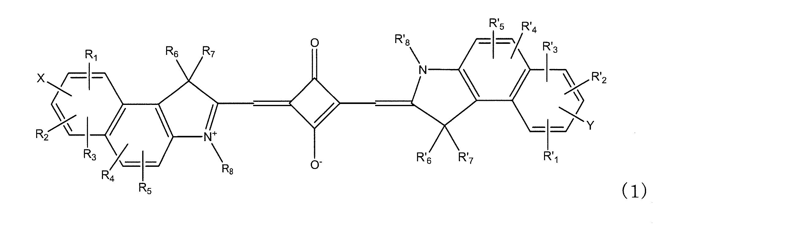
- the squarylium dye includes a squarylium dye represented by the following formula (2).
- R 1 to R 5 , R ′ 1 to R ′ 5 , R 6 to R 7 , R ′ 6 to R ′ 7 , X, Y, R 8 and R ′ 8 are the same as in formula (1).
- R 1 to R 5 and R ′ 1 to R ′ 5 are independently a hydrogen atom or a halogen atom
- R 6 to R 7 and R ′ 6 to R ′ 7 are independently C1 to C12.
- alkyl group a C1-C4 sulfoalkyl group, a C4-C12 cycloalkyl group, a C1-C12 alkoxyl group, a C5-C12 aryl group, a C6-C12 aromatic alkoxyl group, or a halogen atom.
- R 1 to R 7 are independently a hydrogen atom, a C1 to C12 alkyl group, a C1 to C4 sulfoalkyl group, a C4 to C12 cycloalkyl group, a C1 to C12 alkoxyl group, or a C5 to C12 aryl group.
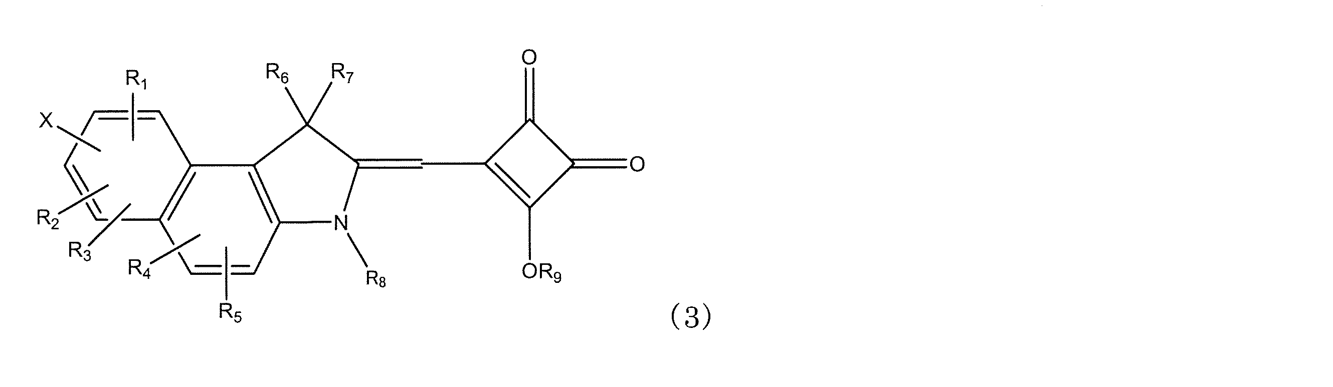
- a group, a C6-C12 aromatic alkoxyl group or a halogen atom, X represents COOR (R is hydrogen or a C1-C12 alkyl group), R 8 is a C3-C30 alkyl group, C3-C30 Represents a halogen-substituted alkyl group, a C3 to C30 hydroxycarbonylalkyl group, or RCOO— or RSO 3 — (R is a C1 to C30 alkyl group); R 9 represents a hydrogen atom or a C1-C12 alkyl group, and when X is other than —COOH, it is hydrogen.
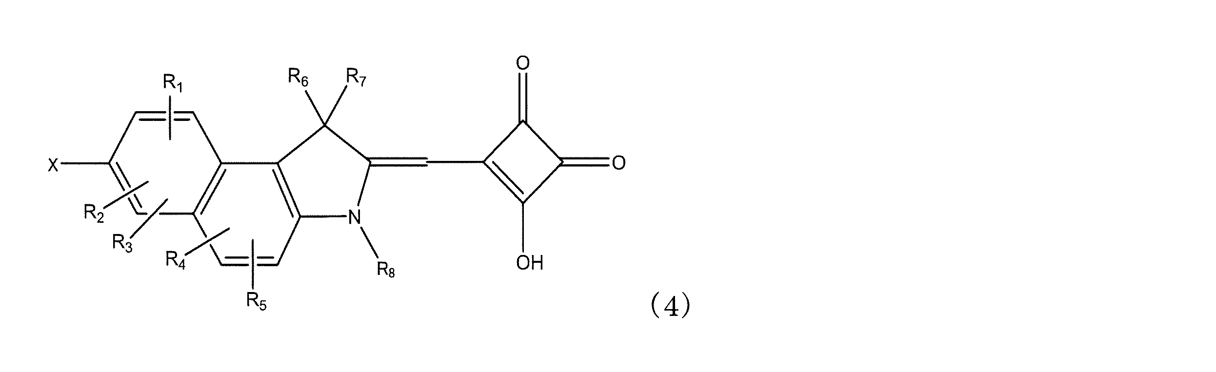
- the semi-squarylium dye includes a squarylium dye represented by the following formula (4).
- R 1 to R 8 , R 9 and X are the same as in the formula (3).
- the present invention also relates to a dye-sensitized solar cell or a photoelectric conversion element, characterized in that the dye used is the above-mentioned squarylium dye or semi-squarylium dye in a dye-sensitized solar cell or photoelectric conversion element using a dye.
- the semi-squarylium dye can be used together with the squarylium dye.
- the substituted benzo [e] indole compound represented by the following general formula (5) is a novel compound, which is useful as an intermediate for the above-mentioned squarylium dye or semi-squarylium dye.
- R 1 to R 7 are the same as in the formula (1).
- X is the same as equation (3).
- R 10 is a C1-C30 alkyl group, and the carbon adjacent to the ring is a primary or secondary carbon.
- R 1 to R 7 , R 10 and X are the same as in the formula (5).
- R 10 is preferably a methyl group.
- the salts of the substituted benzo [e] indole compounds represented by the above general formulas (5) and (6) are also novel compounds, which are useful as intermediates for the above-mentioned squarylium dyes or semi-squarylium dyes.
- These salts are represented by the following formula (7), preferably formula (8).
- R 1 to R 8 are the same as in the formula (1).
- R 10 and X are the same as in formula (5).
- Z ⁇ represents a halogen ion serving as a counter anion, BF 4 — or CClO 4 — , but when R 8 is RCOO— or RSO 3 —, Z ⁇ does not exist.
- R 1 to R 8 , R 10 , Z 2 - and X are the same as in formula (7).
- R 10 is preferably a methyl group.
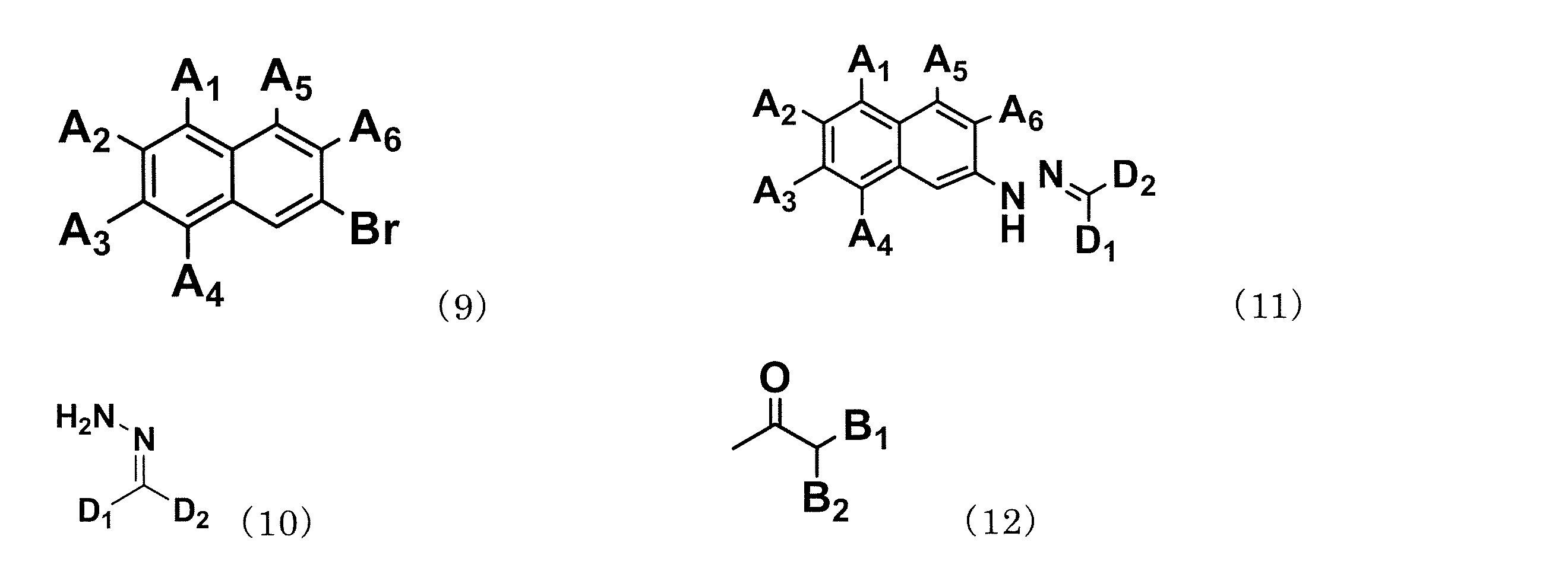
- the above substituted benzo [e] indole compound is a compound of the following formula (9) and a compound of the following formula (10) in the presence of palladium acetate and 2,2′-bis (diphenylphosphino) -1,1′-binaphthyl.
- the esterified aryl hydrazine of the following formula (11) is produced by reacting under the following conditions, and this esterified aryl hydrazine and the ketone of the following formula (12) are further reacted in the presence of paratoluenesulfonic acid monohydrate. It can manufacture by performing a process sequentially.
- a 1 to A 6 and B 1 to B 2 are a hydrogen atom, a C1 to C12 alkyl group, a C1 to C4 sulfoalkyl group, a C4 to C12 cycloalkyl group, a C1 to C12 alkoxyl group, a C6 to C2 A C12 aryl group, a C6 to C12 aromatic alkoxyl group or a halogen atom, and at least one of A 1 to A 6 is a COOH group or COOR (R is a C1 to C12 alkyl group).
- D 1 to D 2 are a C1 to C12 alkyl group, a C4 to C12 cycloalkyl group, or a C6 to C12 aryl group.
- a 1 to A 6 give R 1 to R 5 and X in the formula (7)
- B 1 to B 2 give R 6 to R 7 .
- the photoelectric conversion element or dye-sensitized solar cell of the present invention contains a squarylium dye represented by the formula (1), a semi-squarylium dye represented by the formula (3), or both as a sensitizing dye.
- a dye-sensitized solar cell utilizes a photoelectric conversion element, since both description is common, a common description is demonstrated on behalf of a dye-sensitized solar cell.
- the squarylium dye of the present invention will be described.
- dye of this invention is represented by Formula (1).
- R 1 to R 7 and R ′ 1 to R ′ 7 are independently a hydrogen atom, a C1 to C12 alkyl group, a C1 to C4 sulfoalkyl group, a C4 to C12 cycloalkyl group, C1 to C12 alkoxyl group, C5 to C12 aryl group, C6 to C12 aromatic alkoxyl group or halogen atom, preferably hydrogen atom, C1 to C6 alkyl group, C1 to C4 sulfoalkyl group, C4 A C6-C6 cycloalkyl group, a C1-C6 alkoxyl group, a C6-C8 aryl group, a C6-C8 aromatic alkoxyl group or a halogen atom.
- R 1 to R 5 and R ′ 1 to R ′ 5 are a hydrogen atom or a halogen atom
- R 6 to R 7 and R ′ 6 to R ′ 7 are C1 to C12 alkyl groups, C1 A C4-sulfoalkyl group, a C4-C12 cycloalkyl group, a C1-C12 alkoxyl group, a C6-C12 aryl group, a C6-C12 aromatic alkoxyl group, or a halogen atom.
- R 1 to R 5 and R ′ 1 to R ′ 5 are hydrogen atoms
- R 6 to R 7 and R ′ 6 to R ′ 7 are methyl groups.
- R 8 and R ′ 8 in the formula (1) independently represent a C1-C30 alkyl group, a C1-C30 halogen-substituted alkyl group, a C1-C30 hydroxycarbonylalkyl group, RCOO— or RSO3—.
- At least one of R 8 and R ′ 8 is a C3 to C30 alkyl group, a C3 to C30 halogen-substituted alkyl group, a C3 to C30 hydroxycarbonylalkyl group, or RCOO— or RSO3—.
- R in RCOO— or RSO3— is a C1-C30 alkyl group, preferably a C3-C20 alkyl group.
- R 8 and R ′ 8 may be the same or different. If either one of R 8 and R ′ 8 is a group of C3 or more, the other may be H or a C1-2 group. If R 8 and R ′ 8 are the same, there is an advantage that synthesis and purification are easy.
- At least one of R 8 and R ′ 8 is a C4 to C20 alkyl group, a C4 to C20 halogen-substituted alkyl group, a C4 to C20 hydroxycarbonylalkyl group, or RCOO— or RSO3—. And more preferably a C4 to C20 alkyl group and a C4 to C20 fluorine-substituted alkyl group.
- R is preferably a C1-C6 alkyl group.
- R 8 and R ′ 8 are preferably independently a C3 to C30 alkyl group, a C3 to C30 halogen-substituted alkyl group, a C3 to C30 hydroxycarbonylalkyl group, or RCOO— or RSO3—.
- R is a C1-C30 alkyl group, preferably a C3-C20 alkyl group, more preferably a C1-C6 alkyl group.
- R 8 and R ′ 8 are substituted alkyl groups, halogen-substituted alkyl groups and hydroxycarbonylalkyl groups are preferred. When a substituent has carbon, the carbon is contained in the said carbon number.
- R 8 and R ′ 8 include a C3 to C30 branched or straight chain alkyl group or a fluorine-substituted alkyl group, and more preferably an n-alkyl group or a fluorine-substituted n-alkyl group.
- at least one of R 8 and R ′ 8 may be the above substituted alkyl group, but it is more preferable that both of them are both.
- X and Y independently represent hydrogen or —COOR (R is hydrogen or a C1-C12 alkyl group), and both or one of X and Y is —COOR.
- R is hydrogen, it becomes a carboxy group.
- R is preferably hydrogen or a C1-C6 alkyl group. More preferably, one of X and Y is —COOH, and the other is —COOH or hydrogen.
- the squarylium dye represented by the formula (2) is preferable.
- R 1 to R 5 , R ′ 1 to R ′ 5 , R 6 to R 7 , R ′ 6 to R ′ 7 , X, Y, R 8 and R ′ 8 are represented by the formula (1) Is an agreement.
- R 1 to R 5 and R ′ 1 to R ′ 5 are independently a hydrogen atom or a halogen atom
- R 6 to R 7 and R ′ 6 to R ′ 7 are Independently, C1-C12 alkyl group, C1-C4 sulfoalkyl group, C4-C12 cycloalkyl group, C1-C12 alkoxyl group, C5-C12 aryl group, C6-C12 aromatic alkoxyl group or halogen. Is an atom.
- the semi-squarylium dye of the present invention will be described.
- dye of this invention is represented by Formula (3).
- the semi-squarylium dye represented by formula (3) is a compound having a structure excluding one of the two benzoindole skeletons of the squarylium dye represented by formula (1), and has a similar structure.
- the squarylium dye represented by the formula (3) can be obtained as an intermediate of the squarylium dye represented by the formula (1).
- This semi-squarylium dye can be used for the same application as the squarylium dye represented by the formula (1).
- it can be used with a squarylium dye of the formula (1).
- a semi-squarylium dye represented by (4) is preferably exemplified.
- R 1 to R 8 have the same meaning as R 1 to R 8 in the formula (1).
- X represents -COOR (R represents hydrogen or a C1-C12 alkyl group).
- R 9 is hydrogen or a C1-C12 alkyl group when X is COOH, and is hydrogen when X is other than COOH.
- X is COOH and R 9 is hydrogen.
- the substituted benzo [e] indole compound represented by the formula (5), (6), (7) and (8) or a salt thereof is represented by the formula (1), (2), (3) or (4): It is an intermediate of the represented squarylium dye or semi-squarylium dye. Accordingly, substituents having the same symbol have the same meaning.
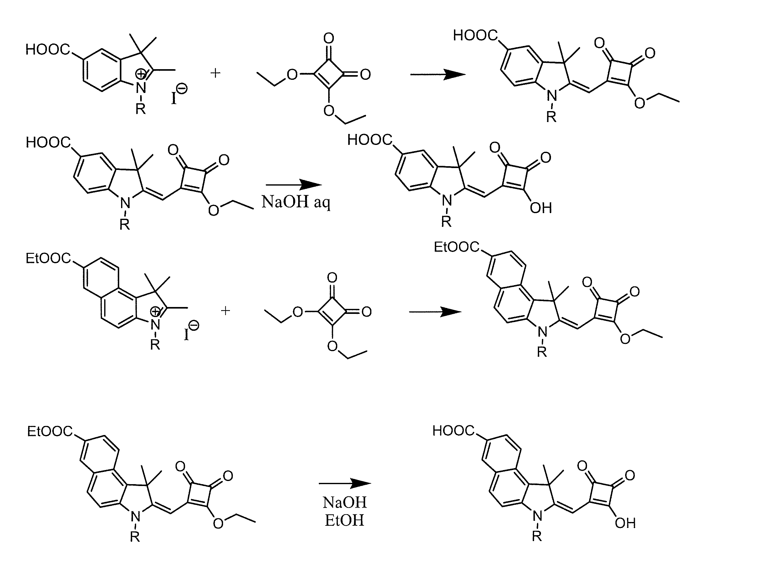
- the synthesis of the squarylium dye represented by the formula (1) is performed by synthesizing a benzoindolenine carboxylic acid ester from a hydrazinonaphthalene carboxylic acid ester and then reacting with an alkyl halide to alkylate the benzoindolenin carboxylic acid ester Synthesize a salt. Next, it can be synthesized by reacting this salt with squaric acid and hydrolyzing the ester moiety.
- Carboxy indolenine is described in Bioconjugate Chem., 2003, Vol. 14, 1048-1051.
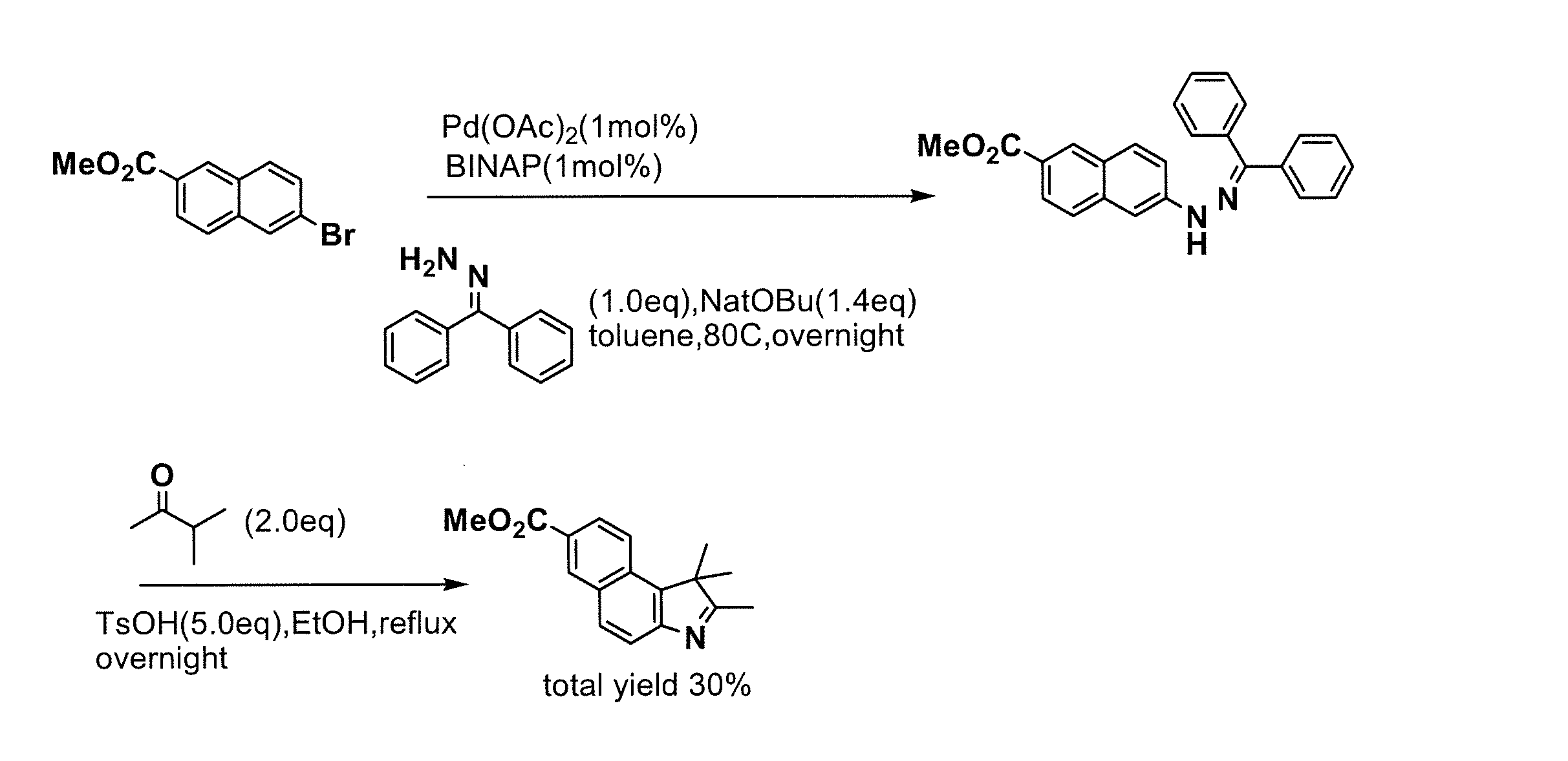
- compound 6 in the following formula can be synthesized from esterified naphthalene bromide with reference to Non-Patent Documents 4 and 5.
- BINAP is 2,2′-bis (diphenylphosphino) -1,1′-binaphthyl.
- N-alkylcarboxybenzoindolenine salts can be synthesized with reference to Dyes Pigments, 11, 1989, p21-35.
- N-alkylcarboxybenzoindolenine salts having different carbon numbers can be synthesized.
- the squarylium dye represented by the formula (1) can be synthesized using N-alkylcarboxyindolenine salt and squaric acid with reference to Dyes Pigments, 11, 1989, p21-35.
- the semi-squarylium dye represented by the formula (2) can be synthesized with reference to Non-Patent Document 2.
- R is a C3-C30 alkyl group.
- the squarylium dye represented by the formula (1) and the semi-squarylium dye represented by the formula (3) are used alone or jointly for the photoelectric conversion element or the dye-sensitized solar cell dye of the present invention.
- the semi-squarylium dye represented by the formula (3) has an absorption region on the relatively short wavelength side, it is excellent as a photoelectric conversion element or dye-sensitized solar cell dye in the short wavelength region. Further, when used in combination with the squarylium dye represented by the formula (1), light is absorbed in a wide range to give a good photoelectric conversion element.
- the semi-squarylium dye represented by the formula (3) is also an intermediate of the squarylium dye represented by the formula (1), it not only has an advantage that it can be synthesized from the same raw material, but also has similar properties. There is an advantage that problems such as deterioration due to interaction when both are used together are less likely to occur.
- the ratio of (1) / (3) is preferably 0.3 to 10, more preferably 1 to 4 range.
- the absorption wavelength range of the sensitizing dye can be selected depending on the light source used.
- the skeleton can be selected to match the wavelength range of the target light source.
- Such a dye preferably has an appropriate interlocking group for the surface of the semiconductor fine particles.
- Preferred linking groups include COOH group, SO 3 H group, cyano group, —P (O) (OH) 2 group, —OP (O) (OH) 2 group, —OH group or oxime, dioxime, hydroxyquinoline, Examples include chelating groups having ⁇ conductivity such as salicylate and ⁇ -ketoenolate. Among these, a COOH group is preferable, and the squarylium dyes represented by the above formulas (1) and (3) are also preferable in that they have a COOH group.
- FIG. 1 is a cross-sectional view showing an example of a photoelectric conversion element.
- a dye-adsorbing semiconductor layer 3 in which a sensitizing dye is adsorbed on a semiconductor layer composed of a conductive layer 2 and one or more layers on a substrate 1.
- the dye adsorbing semiconductor layer 3 is also referred to as a semiconductor electrode because it forms part of the electrode.
- the dye-adsorbing semiconductor layer 3 is a layer coated or sintered as a single layer using titania or metal oxide fine particles, or a layer formed by applying and sintering a plurality of times. This layer is composed of metal oxide particles such as titanium oxide particles and a sensitizing dye present so as to cover the surface of the particles. Light enters from the surface electrode 10 side.
- the dye-sensitized solar cell of the present invention has the same basic configuration as described above, but is made to work in an external circuit. A method of using a dye photoelectric conversion element as a dye-sensitized solar cell is known in Patent Documents 1 and 2, etc., and these known methods may be used.
- the substrate 1 is not particularly limited as long as it is a transparent insulating material, and examples thereof include a normal glass plate and a plastic plate, and further, a flexible one may be used, for example, a PET resin. However, it is preferably a heat-resistant material that can withstand the step of baking titanium oxide with an upper limit of about 500 ° C., and a transparent glass plate can be mentioned.
- a conductive layer 2 is provided on the surface of the substrate 1 so as not to impair the transparency of the base material.
- the conductive layer ITO, FTO, ATO known as a so-called transparent electrode, or a combination thereof is used. Moreover, it may be a metal layer having a thickness that does not impair the transparency.
- the method for providing these conductive layers is not particularly limited, and includes spin coating, bar coating, screen printing using sputtering, vapor deposition (including CVD and PVD), spraying, laser ablation, or pasted materials. Known techniques can be used. Among them, a spray method or a sputtering or vapor deposition method performed in a gas phase is suitable.
- a sensitizing dye is adsorbed thereto.
- a metal oxide what is known as a photoelectric conversion material can be used, and titanium oxide, zinc oxide, tungsten oxide, and the like can be used. Of these, titanium oxide is preferable. Titanium oxide may be titanium hydroxide such as anatase type, rutile type, brookite type, titanium hydroxide or hydrous titanium oxide. Further, at least one of each element of Nb, V, or Ta may be doped so as to have a weight concentration (as a metal element) of 30 ppm to 5% with respect to titanium oxide. Such a metal oxide can be used in the present invention, but fine particles having an average particle diameter of 5 to 500 nm, preferably 10 to 200 nm are preferable.
- a metal oxide layer is formed on the conductive layer 2, but the method is not particularly limited. For example, each method such as spin coating, printing, spray coating, or the like is used to paste a metal oxide. May be. It is also possible to sinter for the purpose of sintering a metal oxide such as titanium oxide after film formation. Next, a dye for sensitization is adsorbed on the metal oxide to form a dye adsorbing semiconductor layer 3 as a dye adsorbing metal oxide.
- the present invention is characterized by a sensitizing dye, and other layers or materials may have a known structure or material, and are not limited to those having the structure shown in FIG.
- the materials constituting the dye-adsorbing semiconductor layer 3 are a semiconductor and a dye.
- the semiconductor is a metal oxide, preferably titanium oxide, the semiconductor may be represented by a metal oxide or titanium oxide.
- the dye for sensitizing dye is a squarylium dye represented by the above formula (1) and / or formula (3). Since the above-mentioned squarylium dye has a large number of carbon atoms in the alkyl group substituted with N, a good photoelectric conversion element and dye-sensitized solar cell are provided.
- the dye is dissolved in a solvent that dissolves the dye and adsorbed on the titania semiconductor layer.
- the adsorption solvent can be used as long as it is a solvent capable of being dyed.
- aliphatic alcohols such as methanol, ethanol, propanol and normal butanol
- nitrile solvents such as acetonitrile and propionitrile
- ketones such as acetone and methyl ethyl ketone
- carbonates such as dimethyl carbonate and diethyl carbonate
- lactones Caprolactams can be used.
- Methanol, ethanol or acetonitrile is preferred.
- the dye solution may be adsorbed using a dye solution in which a co-adsorbent such as deoxycholic acid or chenodeoxycholic acid (DCA) is dissolved.
- a co-adsorbent such as deoxycholic acid or chenodeoxycholic acid (DCA) is dissolved.
- the dye may be dissolved and adsorbed in a supercritical fluid or a pressurized fluid. Specifically, it is preferably adsorbed by carbon dioxide or a solution obtained by adding an entrainer to carbon dioxide.
- the metal oxide adsorbed with the dye may be further adsorbed with carboxylic acid in a CO 2 supercritical fluid.
- carboxylic acid The effect of adsorbing carboxylic acid is known from non-patent document J. Photochem. And Photobio. A, Chem. 164 (2004) 117.
- CO formed from a metal oxide adsorbed with a dye (which may be a substrate having a metal oxide layer adsorbed with a dye) and a carboxylic acid in a pressure range of 5 to 30 MPa and a temperature range of 40 to 60 ° C.
- carboxylic acid by placing the supercritical fluid or in the pressure CO 2, it can effectively adsorb the carboxylic acid.
- Preferred examples of the carboxylic acid include benzoic acid, acetic acid, anisic acid, and nicotinic acid. These carboxylic acids are preferably used in a state dissolved in an alcohol containing at least one of methanol, ethanol, propanol and butanol, and the carboxylic acid concentration is in the range of 0.01 to 10 mol / L. It is preferable.
- the surface electrode 10 composed of the substrate 1, the conductive layer 2, and the dye-adsorbing semiconductor layer 3 functions as a negative electrode.
- the other electrode (counter electrode) 11 acting as the positive electrode is disposed to face the surface electrode 10 as shown in FIG.
- the electrode serving as the positive electrode may be a conductive metal or the like, or may be a substrate 4 such as a normal glass plate or plastic plate provided with a conductive layer 5 such as a metal film or a carbon film.
- An electrolyte layer 6 is provided between the surface electrode 10 serving as the negative electrode and the counter electrode 11 serving as the positive electrode.
- the type of the electrolyte constituting the electrolyte layer 6 is not particularly limited as long as it contains a redox species for reducing the dye after photoexcitation and electron injection into the semiconductor, and even if it is a liquid electrolyte Alternatively, it may be a gelled electrolyte obtained by adding a known gelling agent (polymer or low molecular weight gelling agent) or a quasi-solid obtained by kneading an ionic liquid and a metal oxide.
- examples of the electrolyte used in the solution electrolyte iodine and iodide (LiI, NaI, KI, CsI, metal iodide such as CaI 2, tetraalkylammonium iodide, pyridinium iodide, such as imidazolium iodide 4 the combination of the combination of grade ammonium compound iodine salt, etc.), bromine and a bromide (LiBr, NaBr, KBr, CsBr , CaBr 2 , etc.
- iodine and iodide LiI, NaI, KI, CsI, metal iodide such as CaI 2, tetraalkylammonium iodide, pyridinium iodide, such as imidazolium iodide 4 the combination of the combination of grade ammonium compound iodine salt, etc.
- metal bromides such as tetraalkylammonium bromide, quaternary ammonium compounds bromine salts such as pyridinium bromide, etc.
- poly Examples thereof include sulfur compounds such as sodium sulfide, alkyl thiol, and alkyl disulfide, viologen dyes, hydroquinone, and quinone.
- the electrolyte may be used as a mixture.
- a molten salt electrolyte having a high boiling point is preferable.
- the molten salt electrolyte composition includes a molten salt.
- the molten salt electrolyte composition is preferably liquid at room temperature.
- the molten salt as the main component is an electrolyte that is liquid at room temperature or has a low melting point, and a general example thereof is “Electrochemistry”, 1997, Vol. 65, No. 11, p. Pyridinium salts, imidazolium salts, and triazolium salts described in No. 923.
- the molten salt may be used alone or in combination of two or more.
- Alkali metal salts such as LiI, NaI, KI, LiBF 4 , CF 3 COOLi, CF 3 COONa, LiSCN, and NaSCN can also be used in combination.
- the molten salt electrolyte composition contains iodine.
- the molten salt electrolyte composition preferably has low volatility and preferably does not contain a solvent.
- the molten salt electrolyte composition may be used after gelation.
- the compound has a low viscosity and high ion mobility and can exhibit excellent ionic conductivity.
- solvents include carbonate compounds such as ethylene carbonate and propylene carbonate, heterocyclic compounds such as 3-methyl-2-oxazolidinone, ether compounds such as dioxane and diethyl ether, ethylene glycol dialkyl ether, propylene glycol dialkyl ether , Chain ethers such as polyethylene glycol dialkyl ether and polypropylene glycol dialkyl ether, alcohols such as methanol, ethanol, ethylene glycol monoalkyl ether, propylene glycol monoalkyl ether, polyethylene glycol monoalkyl ether and polypropylene glycol monoalkyl ether, ethylene Glycol, propylene glycol, polyethylene glycol, polypropylene glycol Lumpur, polyhydric alcohols such as glycerin, acetonitrile
- the method of providing the electrolyte layer 6 is not particularly limited.
- a film-like spacer 7 may be disposed between both electrodes to form a gap, and an electrolyte may be injected into the gap.
- a method may be employed in which the positive electrode is loaded at an appropriate interval after the electrolyte is applied to the electrode. It is desirable to seal both electrodes and their surroundings so that the electrolyte does not flow out, but the sealing method and the material of the sealing material are not particularly limited.
- Synthesis Examples 1 to 9 and 13 are examples (excluding Dye D-6).
- Ethoxycarbonylbenzoindolenine was synthesized using commercially available reagents such as 1-bromo-4-ethoxycarbonylnaphthalene, benzophenone hydrazone, palladium acetate, BINAP, sodium butoxide, methyl isopropyl ketone, and p-toluenesulfonic acid. 78.87 mmol of 1-bromo-4-ethoxycarbonylnaphthalene was dissolved in a toluene solvent, palladium acetate and BINAP were added, and then 78.87 mol of benzohydrazone and sodium butoxide were added and reacted at 80 ° C. overnight.
- reagents such as 1-bromo-4-ethoxycarbonylnaphthalene, benzophenone hydrazone, palladium acetate, BINAP, sodium butoxide, methyl isopropyl ketone, and p-toluenesul
- Synthesis example 2 The synthesis of Nn-alkylethoxycarbonylbenzoindolenine salt involves dissolving 0.1 mol of 2,3,3-trimethyl-6-ethoxycarbonylbenzoindolenine and 1-iodine ethane in 20 ml of ethanol and reacting for 7 hours while refluxing. I let you. The solid content was filtered to obtain 1-n-ethyl-2,3,3-trimethyl-6-ethoxycarbonylbenzoindolenium iodide in a yield of 55%.
- Synthesis example 3 The synthesis of Nn-alkylethoxycarbonylbenzoindolenine salt involves dissolving 0.1 mol of 2,3,3-trimethyl-6-ethoxycarbonylbenzoindolenine and 1-butane iodide in 20 ml of ethanol and reacting for 48 hours while refluxing. I let you. The solid content was filtered to obtain 1-n-butyl-2,3,3-trimethyl-6-ethoxycarbonylbenzoindolenium iodide in a yield of 55%.
- Synthesis example 4 The synthesis of Nn-alkylethoxycarbonylbenzoindolenine salt was performed by dissolving 0.1 mol of 2,3,3-trimethyl-6-ethoxycarbonylbenzoindolenin and 1-octane iodide in 20 ml of ethanol and reacting for 72 hours while refluxing. I let you. The solid content was filtered to obtain 1-n-octyl-2,3,3-trimethyl-6-ethoxycarbonylbenzoindolenium iodide in a yield of 55%.
- Synthesis Example 6 When synthesizing ethoxycarbonylbenzoindolenine salt, squarylium dyes D-2 and D were synthesized in the same manner as in Synthesis Example 5 except that 1-iodinated octane or 1-iodoethane was used instead of 1-iodobutane. -6 was obtained.
- the IR spectrum of squarylium dye D-2 is shown in FIG.
- Synthesis example 7 Semi-squarylium was synthesized by reacting an asymmetric squarylium dye with carboxyindolenine salts and squaric acid esters one by one. Subsequently, the other indolenine salt was reacted to synthesize an asymmetric squarylium dye.
- a benzoindolenin salt obtained by synthesizing renin and alkylating with 1-iodine octane an asymmetric squarylium dye D- with reference to J. Am. Chem. Soc. 3 was synthesized.
- Synthesis example 8 As a carboxyindolenine salt, a carboxyindolenine salt obtained by using 1-iodinated octane in Synthesis Example 3 and a benzoindolenine salt as 1-bromo-4-ethoxycarbonylnaphthalene in Synthesis Example 1 instead of 1- A benzoindolenine obtained using bromonaphthalene was synthesized, and further benzoindolenine salt alkylated with 1-iodinated octane was used, and J. Am. Chem. Soc. For reference, an asymmetric type squarylium dye D-4 was synthesized.
- Synthesis Example 9 As a carboxyindolenine salt, a carboxyindolenin salt obtained by using 1-iodobutane in Synthesis Example 2 and a semi-squarylium ester obtained by using succinic acid butyl ester were hydrolyzed with an aqueous sodium hydroxide solution, Semi-squarylium dye D-5 was synthesized.
- Synthesis Example 11 As a carboxyindolenine salt, ethyl 4-bromobenzoate was used instead of 1-bromo-4-ethoxycarbonylnaphthalene in Synthesis Example 1, and 1-iodination was used instead of 1-iodobutane in Synthesis Example 3.
- Symmetric squarylium dye D-8 was synthesized in the same manner as in Synthesis Example 5 using ethane.
- Synthesis Example 12 As a carboxyindolenine salt, ethyl 4-bromobenzoate was used instead of 1-bromo-4-ethoxycarbonylnaphthalene in Synthesis Example 1, and 1-iodination was used instead of 1-iodobutane in Synthesis Example 3.
- Symmetric squarylium dye D-9 was synthesized in the same manner as in Synthesis Example 5 using propionic acid.
- Synthesis Example 13 As a carboxyindolenine salt, 1,1,1-trifluoro-4-iodobutane was used in place of 1-iodobutane in Synthesis Example 3, and symmetric squarylium dye D-10 was prepared in the same manner as in Synthesis Example 5.
- a carboxyindolenine salt 1,1,1-trifluoro-4-iodobutane was used in place of 1-iodobutane in Synthesis Example 3, and symmetric squarylium dye D-10 was prepared in the same manner as in Synthesis Example 5.
- symmetric squarylium dye D-10 was prepared in the same manner as in Synthesis Example 5.
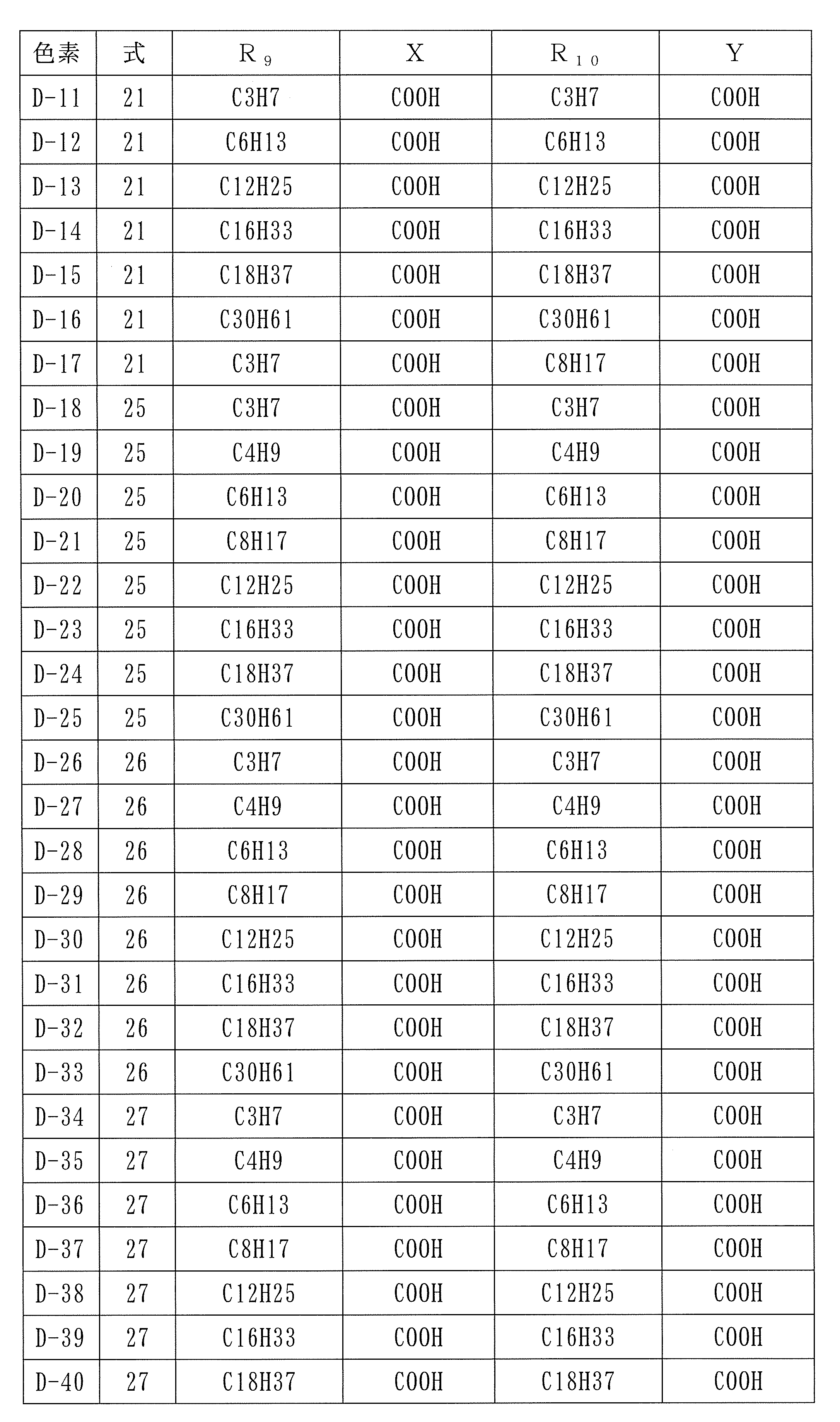
- squarylium dye or semi-squarylium dye of the present invention are shown in structural formulas 21 to 37 and Tables 1 to 3.
- R 9 , R 10 , X and Y correspond to the symbols attached to the structural formulas.
- Table 1 shows the maximum absorption wavelength ( ⁇ max) in R 9 , R 10 , X and Y and the ultraviolet-visible region of the squarylium dyes or semi-squarylium dyes D-1 to D-10 obtained in Synthesis Examples 1 to 13.
- Example 1 As a glass substrate with a transparent conductive film of 30 mm ⁇ 25 mm ⁇ 3 mm, a glass substrate with FTO (fluorine-doped tin oxide) film (trade name: Low-E glass) made of Japanese plate glass was used. Next, a titanium oxide film was formed on the conductive film of the substrate with the conductive film. As titanium oxide, a commercially available titanium oxide paste (D paste made by Solaronics) was used. A laminated board in which a titanium oxide layer having a thickness of 15 ⁇ m was formed by coating this onto a conductive film of a substrate with a conductive film by a squeegee printing method in a range of 5 mm ⁇ 5 mm, drying and baking at 450 ° C. Obtained.
- FTO fluorine-doped tin oxide
- D-1 was used as the dye. This was dissolved in ethanol so as to be 3 ⁇ 10 ⁇ 4 mol / L and DCA to be 3 ⁇ 10 ⁇ 3 mol / L.
- For dye adsorption prepare a dye solution by dissolving the dye in a solvent, place the dye solution in a container, place a laminated plate on which the titanium oxide layer is formed, and let the dye adsorb from the container after standing for 2 hours. The board was removed.
- thermoplastic adhesive product name: Mitsui DuPont Polychemical Co., Ltd .; High Milan Sheet
- This thermoplastic adhesive is not only a sealing material but also serves as a spacer between the two electrodes.
- a glass substrate on which a platinum film having a thickness of 10 nm serving as a positive electrode was formed by a sputtering method was bonded through the thermoplastic adhesive film so that the platinum side was opposed to the titanium oxide side.
- thermoplastic adhesive films From the gap between the thermoplastic adhesive films, an acetonitrile solution containing 0.5M LiI, 0.5M t-butylpyridine, and 0.05M iodine as the main component is filled between the substrate and the positive electrode using capillary action. It was. Immediately after filling the electrolyte, the gap was sealed with an epoxy resin adhesive to obtain a photoelectric conversion element.
- Examples 2-5 A photoelectric conversion element was obtained in the same manner as in Example 1 except that the dye D-2, D-3, D-4, or D-5 was used.
- Example 6 Dye D-1 is dissolved in ethanol so that 2.25 ⁇ 10 -4 mol / L, D-5 is 0.75 ⁇ 10 -4 mol / L and DCA is 3.0x10 -3 mol / L.
- the photoelectric conversion element was obtained like Example 1 except doing.
- Example 7 A photoelectric conversion element was obtained in the same manner as in Example 1 except that Example 1 was used using Dye D-10.
- Comparative Examples 1 to 4 A photoelectric conversion element was obtained in the same manner as in Example 1 except that the dye D-6, D-7, D-8 or D-9 was used instead of the dye D-1.
- a photoelectric conversion element using the squarylium dye or semi-squarylium dye of the present invention or a dye-sensitized solar cell composed thereof has high photoelectric conversion efficiency in the near-infrared light region.
- by using semi-squarylium dye together with this squarylium dye light from 400 nm to 830 nm can be absorbed, and the photoelectric conversion efficiency is further improved by the synergistic effect of the two dyes without using expensive Ru dye.
- the squarylium dye of the present invention provides a photoelectric conversion element having a high photoelectric conversion efficiency or a dye-sensitized solar cell composed thereof.
Landscapes
- Chemical & Material Sciences (AREA)
- Engineering & Computer Science (AREA)
- Organic Chemistry (AREA)
- Power Engineering (AREA)
- Materials Engineering (AREA)
- Electrochemistry (AREA)
- Spectroscopy & Molecular Physics (AREA)
- Physics & Mathematics (AREA)
- General Chemical & Material Sciences (AREA)
- Chemical Kinetics & Catalysis (AREA)
- Microelectronics & Electronic Packaging (AREA)
- Hybrid Cells (AREA)
- Photovoltaic Devices (AREA)
Abstract
Description



式中、R1~R8、R10、Z-及びXは、式(7)と同意である。R10は好ましくは、メチル基である。
式(3)及び(4)において、同じ記号は同じ意味を有する。そして、R1~R8は、式(1)のR1~R8と同じ意味を有する。Xは-COOR(Rは水素又はC1~C12のアルキル基である)を表す。R9は、XがCOOHの場合は、水素又はC1~C12のアルキル基であり、XがCOOH以外の場合は水素である。好ましくは、XがCOOHであり、R9は水素である。




N-n-アルキルエトキシカルボニルベンゾインドレニン塩の合成は、2,3,3‐トリメチル-6-エトキシカルボニルベンゾインドレニン0.1molと1-ヨウ化エタンを20mlのエタノールに溶かし、還流しながら7時間反応させた。固形分をろ過し、1-n-エチル-2,3,3-トリメチル-6-エトキシカルボニルベンゾインドレニウムアイオダイドを55%の収率で得た。
N-n-アルキルエトキシカルボニルベンゾインドレニン塩の合成は、2,3,3‐トリメチル-6-エトキシカルボニルベンゾインドレニン0.1molと1-ヨウ化ブタンを20mlのエタノールに溶かし、還流しながら48時間反応させた。固形分をろ過し、1-n-ブチル-2,3,3-トリメチル-6-エトキシカルボニルベンゾインドレニウムアイオダイドを55%の収率で得た。
N-n-アルキルエトキシカルボニルベンゾインドレニン塩の合成は、2,3,3‐トリメチル-6-エトキシカルボニルベンゾインドレニン0.1molと1-ヨウ化オクタンを20mlのエタノールに溶かし、還流しながら72時間反応させた。固形分をろ過し、1-n-オクチル-2,3,3-トリメチル-6-エトキシカルボニルベンゾインドレニウムアイオダイドを55%の収率で得た。
スクアリリウム色素の合成は、1-n-ブチル-2,3,3-トリメチル-5-エトキシカルボニル-ベンゾインドレニウムアイオダイド0.7mmolとスクアリン酸3mmolを40mlの容積比ベンゼン:ブタノール=1:4の溶媒に溶かし、1mlのキノリンを加え、水を除去しながら還流し15時間反応させた。室温に冷却し、固形分をろ過した。ジエチルエーテルで固形分を洗浄し、スクアリリウム色素のエステル体を得た。カラム精製した後、水酸化ナトリウム水溶液で加水分解し目的のスクアリリウム色素D‐1を得た。
エトキシカルボニルベンゾインドレニン塩を合成する際に、1-ヨウ化ブタンの代わりに1-ヨウ化オクタン又は1-ヨウ化エタンを使用した以外は合成例5と同様にしてスクアリリウム色素D‐2、D-6を得た。スクアリリウム色素D‐2のIRスペクトルを図2に示す。
非対称スクアリリウム色素はカルボキシインドレニン塩とスクアリン酸エステルを1当量ずつ反応させ、セミスクアリリウムを合成した。その後続けて、もう一方のインドレニン塩を反応させ非対称型スクアリリウム色素を合成した。
カルボキシベンゾインドレニン塩として合成例2で得られたものと、別にベンゾインドレニン塩として合成例1における1-ブロモ-4-エトキシカルボニルナフタリンの代わりに1-ブロモナフタリンを用いて得られたベンゾインドレニンを合成し、さらにこれを1-ヨウ化オクタンを用いてアルキル化したベンゾインドレニン塩を用い、J.Am.Chem.Soc., 129,p10320-10321.を参考に非対称型スクアリリウム色素D-3を合成した。
カルボキシインドレニン塩として、合成例3における1-ヨウ化オクタン用いて得られたカルボキシインドレニン塩と、別にベンゾインドレニン塩として合成例1における1-ブロモ-4-エトキシカルボニルナフタリンの代わりに1-ブロモナフタリンを用いて得られたベンゾインドレニンを合成し、さらにこれを1-ヨウ化オクタンを用いてアルキル化したベンゾインドレニン塩を用い、J.Am.Chem.Soc. 129,p10320-10321を参考に非対称型スクアリリウム色素D-4を合成した。
カルボキシインドレニン塩として、合成例2における1-ヨウ化ブタンを用いて得られたカルボキシインドレニン塩とスクアリ酸ブチルエステルを使用して得られたセミスクアリリウムエステルを水酸化ナトリウム水溶液で加水分解し、セミスクアリリウム色素D-5を合成した。
カルボキシインドレニン塩として、合成例4で得られたものを用い、もう一方としてメチルキノリンをエチル化したヨード塩とを用い合成例8と同様の方法で、非対称スクアリリウム色素D-7を合成した。
カルボキシインドレニン塩として、合成例1において、1-ブロモ-4-エトキシカルボニルナフタリンの代わりに、4-ブロモ安息香酸エチルを用い、合成例3において、1-ヨウ化ブタンの代わりに1-ヨウ化エタンを用い、合成例5と同様の方法で、対称スクアリリウム色素D-8を合成した。
カルボキシインドレニン塩として、合成例1において、1-ブロモ-4-エトキシカルボニルナフタリンの代わりに、4-ブロモ安息香酸エチルを用い、合成例3において、1-ヨウ化ブタンの代わりに1-ヨウ化プロピオン酸を用い、合成例5と同様の方法で、対称スクアリリウム色素D-9を合成した。
カルボキシインドレニン塩として、合成例3において、1-ヨウ化ブタンの代わりに1,1,1-トリフオロ-4-ヨウ化ブタンを用い、合成例5と同様の方法で、対称スクアリリウム色素D-10を合成した。



30mm×25mm×3mmの透明導電膜付ガラス基板として日本板ガラス製のFTO(フッ素ドープ酸化スズ)膜付ガラス基板(商品名:Low‐Eガラス)を使用した。
次に、導電性膜付き基板の導電性膜上に、酸化チタン膜を形成した。酸化チタンは、市販の酸化チタンペースト(ソラロニクス社製Dペースト)を使用した。これを、導電性膜付き基板の導電性膜上に、スキージ印刷の手法で5mm×5mmの範囲に塗工し、乾燥後450℃で焼成して厚み15μmの酸化チタン層を形成した積層板を得た。
色素D-2、D-3、D-4又はD-5を用いた他は、実施例1と同様にして、光電変換素子を得た。
色素D-1を2.25×10⁻⁴mol/LとD-5を0.75×10-4mol/LとDCAを3.0x10-3mol/Lとなるようエタノールに溶かし、2種類の色素を混合吸着する他は、実施例1と同様にして光電変換素子を得た。
色素D-10を用い実施例1を用いた他は、実施例1と同様にして、光電変換素子を得た。
色素D-1に代えて色素D-6、D-7、D-8又はD-9を使用した他は、実施例1と同様にして光電変換素子を得た。

Claims (11)
- 下記式(1)で表わされるスクアリリウム色素。
式中、R1~R7、及びR'1~R'7は独立に、水素原子、C1~C12のアルキル基、C1~C4のスルホアルキル基、C4~C12のシクロアルキル基、C1~C12のアルコキシル基、C5~C12のアリール基、C6~C12の芳香族アルコキシル基又はハロゲン原子を表し、X及びYは独立に水素又は-COOR(Rは水素又はC1~C12のアルキル基である)を表し、少なくとも一方は-COORであり、R8及びR'8は独立に、C1~C30のアルキル基、C1~C30のハロゲン置換アルキル基、C1~C30のヒドロキシカルボニルアルキル基又はRCOO-又はRSO3-(RはC1~C30のアルキル基である)を表すが、少なくとも一方が、C3~C30のアルキル基、C3~C30のハロゲン置換アルキル基、C3~C30のヒドロキシカルボニルアルキル基又はRCOO-又はRSO3-(RはC1~C30のアルキル基である)である。
- 式(1)において、R1~R7、及びR'1~R'7は独立に、水素原子、C1~C12のアルキル基、C1~C4のスルホアルキル基、C4~C12のシクロアルキル基、C1~C12のアルコキシル基、C5~C12のアリール基、C6~C12の芳香族アルコキシル基又はハロゲン原子であり、X及びYは独立に水素又は-COOR(Rは水素又はC1~C12のアルキル基である)であり、少なくとも一方は-COORであり、R8及びR'8は独立に、C3~C30のアルキル基、C3~C30のハロゲン置換アルキル基、C3~C30のヒドロキシカルボニルアルキル基又はRCOO-又はRSO3-(RはC1~C30のアルキル基である)である請求項1に記載のスクアリリウム色素。
- 下記式(2)で表わされる請求項1に記載のスクアリリウム色素。
式中、R1~R5、R'1~R'5、R6~R7、R'6~R'7、X、Y、R8及びR'8は式(1)と同意である。
- 式(2)において、R1~R5、及びR'1~R'5は独立に、水素原子又はハロゲン原子であり、R6~R7、及びR'6~R'7は独立に、C1~C12のアルキル基、C1~C4のスルホアルキル基、C4~C12のシクロアルキル基、C1~C12のアルコキシル基、C5~C12のアリール基、C6~C12の芳香族アルコキシル基又はハロゲン原子である請求項3に記載のスクアリリウム色素。
- スクアリリウム色素を用いる光電変換素子において、スクアリリウム色素が請求項1に記載のスクアリリウム色素であることを特徴とする光電変換素子。
- 請求項5に記載の光電変換素子を用いて構成したことを特徴とする色素増感太陽電池。
- 下記式(3)で表わされるセミスクアリリウム色素。
式中、R1~R7は独立に、水素原子、C1~C12のアルキル基、C1~C4のスルホアルキル基、C4~C12のシクロアルキル基、C1~C12のアルコキシル基、C5~C12のアリール基、C6~C12の芳香族アルコキシル基又はハロゲン原子を表し、XはCOOR(Rは水素又はC1~C12のアルキル基である)を表し、R8はC3~C30のアルキル基、C3~C30のハロゲン置換アルキル基、C3~C30のヒドロキシカルボニルアルキル基又はRCOO-若しくはRSO3-(RはC1~C30のアルキル基である)を表す。R9は水素原子又はC1~C12のアルキル基を表すが、Xが-COOH以外の場合は、水素原子である。
- 下記式(4)で表わされる請求項7に記載のセミスクアリリウム色素。
式中、R1~R8、R9、Xは、式(3)と同意である。
- 色素を用いる光電変換素子において、色素がセミスクアリリウム色素であり、セミスクアリリウム色素が請求項7に記載のセミスクアリリウム色素であることを特徴とする光電変換素子。
- 色素を用いる光電変換素子において、請求項1に記載のスクアリリウム色素と共に、請求項7に記載のセミスクアリリウム色素を用いる請求項5に記載の光電変換素子。
- 請求項9又は10に記載の光電変換素子を用いて構成したことを特徴とする色素増感太陽電池。
Priority Applications (3)
| Application Number | Priority Date | Filing Date | Title |
|---|---|---|---|
| JP2012503122A JP5725459B2 (ja) | 2010-03-02 | 2011-02-28 | スクアリリウム色素及びそれらの色素を用いた色素増感太陽電池、光電変換素子 |
| CN201180011660.4A CN102812093B (zh) | 2010-03-02 | 2011-02-28 | 方酸菁色素及使用它们的色素的敏化太阳能电池、光电转换元件 |
| KR1020127024735A KR20130045847A (ko) | 2010-03-02 | 2011-02-28 | 스쿠아릴륨 색소 및 그 색소들을 이용한 색소증감 태양전지, 광전변환소자 |
Applications Claiming Priority (2)
| Application Number | Priority Date | Filing Date | Title |
|---|---|---|---|
| JP2010-045902 | 2010-03-02 | ||
| JP2010045902 | 2010-03-02 |
Publications (1)
| Publication Number | Publication Date |
|---|---|
| WO2011108481A1 true WO2011108481A1 (ja) | 2011-09-09 |
Family
ID=44542133
Family Applications (1)
| Application Number | Title | Priority Date | Filing Date |
|---|---|---|---|
| PCT/JP2011/054477 Ceased WO2011108481A1 (ja) | 2010-03-02 | 2011-02-28 | スクアリリウム色素及びそれらの色素を用いた色素増感太陽電池、光電変換素子 |
Country Status (5)
| Country | Link |
|---|---|
| JP (1) | JP5725459B2 (ja) |
| KR (1) | KR20130045847A (ja) |
| CN (1) | CN102812093B (ja) |
| TW (1) | TW201202194A (ja) |
| WO (1) | WO2011108481A1 (ja) |
Cited By (1)
| Publication number | Priority date | Publication date | Assignee | Title |
|---|---|---|---|---|
| CN104284943A (zh) * | 2012-05-07 | 2015-01-14 | 索尼公司 | 用于电子器件中的含有方形酸或克酮酸部分的有机化合物 |
Families Citing this family (4)
| Publication number | Priority date | Publication date | Assignee | Title |
|---|---|---|---|---|
| CN103214410B (zh) * | 2013-04-03 | 2016-01-06 | 四川大学 | 一系列不对称方酸菁小分子及其制备方法和应用 |
| WO2016181389A1 (en) * | 2015-05-11 | 2016-11-17 | Bromine Compounds Ltd. | An additive for a flow battery |
| CN105486820B (zh) * | 2016-01-13 | 2017-12-01 | 南京波瑞自动化科技有限公司 | 一种带有气体检测功能的户外视频监控设备 |
| CN105928995B (zh) * | 2016-05-31 | 2018-04-03 | 苏州大学 | 一种基于方酸菁聚合物的湿敏传感器及其制备方法和用途 |
Citations (5)
| Publication number | Priority date | Publication date | Assignee | Title |
|---|---|---|---|---|
| JPH08507317A (ja) * | 1993-02-18 | 1996-08-06 | イーストマン ケミカル カンパニー | 共重合された近赤外蛍光化合物を含有する水散逸性ポリエステル及びアミド |
| JP2000294306A (ja) * | 1999-04-06 | 2000-10-20 | Fuji Photo Film Co Ltd | 光電変換素子および光電気化学電池 |
| JP2000357809A (ja) * | 1999-06-15 | 2000-12-26 | Fuji Photo Film Co Ltd | 光電変換材料、光電変換素子及びポリメチン色素 |
| JP2001040234A (ja) * | 1999-08-03 | 2001-02-13 | Fuji Photo Film Co Ltd | 新規色素化合物 |
| WO2010104117A1 (ja) * | 2009-03-12 | 2010-09-16 | 新日鐵化学株式会社 | 色素増感太陽電池、光電変換素子及びそれに使用される色素 |
-
2011
- 2011-02-28 JP JP2012503122A patent/JP5725459B2/ja not_active Expired - Fee Related
- 2011-02-28 WO PCT/JP2011/054477 patent/WO2011108481A1/ja not_active Ceased
- 2011-02-28 CN CN201180011660.4A patent/CN102812093B/zh not_active Expired - Fee Related
- 2011-02-28 KR KR1020127024735A patent/KR20130045847A/ko not_active Withdrawn
- 2011-03-02 TW TW100106905A patent/TW201202194A/zh unknown
Patent Citations (5)
| Publication number | Priority date | Publication date | Assignee | Title |
|---|---|---|---|---|
| JPH08507317A (ja) * | 1993-02-18 | 1996-08-06 | イーストマン ケミカル カンパニー | 共重合された近赤外蛍光化合物を含有する水散逸性ポリエステル及びアミド |
| JP2000294306A (ja) * | 1999-04-06 | 2000-10-20 | Fuji Photo Film Co Ltd | 光電変換素子および光電気化学電池 |
| JP2000357809A (ja) * | 1999-06-15 | 2000-12-26 | Fuji Photo Film Co Ltd | 光電変換材料、光電変換素子及びポリメチン色素 |
| JP2001040234A (ja) * | 1999-08-03 | 2001-02-13 | Fuji Photo Film Co Ltd | 新規色素化合物 |
| WO2010104117A1 (ja) * | 2009-03-12 | 2010-09-16 | 新日鐵化学株式会社 | 色素増感太陽電池、光電変換素子及びそれに使用される色素 |
Cited By (1)
| Publication number | Priority date | Publication date | Assignee | Title |
|---|---|---|---|---|
| CN104284943A (zh) * | 2012-05-07 | 2015-01-14 | 索尼公司 | 用于电子器件中的含有方形酸或克酮酸部分的有机化合物 |
Also Published As
| Publication number | Publication date |
|---|---|
| JPWO2011108481A1 (ja) | 2013-06-27 |
| CN102812093A (zh) | 2012-12-05 |
| KR20130045847A (ko) | 2013-05-06 |
| TW201202194A (en) | 2012-01-16 |
| JP5725459B2 (ja) | 2015-05-27 |
| CN102812093B (zh) | 2014-01-15 |
Similar Documents
| Publication | Publication Date | Title |
|---|---|---|
| JP5527620B2 (ja) | 色素増感太陽電池、光電変換素子及びそれに使用される色素 | |
| JP4841248B2 (ja) | 色素増感光電変換素子 | |
| JP4963343B2 (ja) | 色素増感光電変換素子 | |
| JP5725459B2 (ja) | スクアリリウム色素及びそれらの色素を用いた色素増感太陽電池、光電変換素子 | |
| JP2008174734A (ja) | 化合物、光電変換素子及び光電気化学電池 | |
| JP5846579B2 (ja) | ポリメチン色素前駆体、その前駆体の骨格を含むスクアリリウム色素、それを用いた色素増感太陽電池、光電変換素子 | |
| JP2002334729A (ja) | 色素増感光電変換素子 | |
| JP6001387B2 (ja) | 光増感色素及びこれを有する色素増感太陽電池 | |
| JP5392765B2 (ja) | 光電変換素子用の色素、光電変換素子及び色素増感太陽電池 | |
| JP5875511B2 (ja) | スクアリリウム色素、これを使用する光電変換素子及び色素増感太陽電池 | |
| JP4230182B2 (ja) | 色素増感光電変換素子及びこれを用いた太陽電池 | |
| KR101597863B1 (ko) | 플루오렌 유도체 및 그의 염 | |
| JP5906522B2 (ja) | フタロシアニン色素並びにフタロシアニン色素を用いた色素増感太陽電池及び光電変換素子 | |
| JP5906489B2 (ja) | ポルフィリン色素並びにポルフィリン色素を用いた色素増感太陽電池及び光電変換素子 | |
| JP2005019130A (ja) | 色素増感光電変換素子 | |
| JP5906521B2 (ja) | フタロシアニン色素並びにフタロシアニン色素を用いた色素増感太陽電池及び光電変換素子 | |
| JP4979914B2 (ja) | 化合物、該化合物を用いた光電変換素子及び光電気化学電池 | |
| JP2012201864A (ja) | シアニン色素、これを用いた色素増感太陽電池及び光電変換素子 | |
| JP2012204284A (ja) | シアニン色素並びにシアニン色素を用いた色素増感太陽電池及び光電変換素子 | |
| JP2013112702A (ja) | 光電変換素子用のスクアリリウム色素、これを使用する光電変換素子及び色素増感太陽電池 | |
| KR101633150B1 (ko) | 플루오렌 유도체 및 그의 염 | |
| JP2014172961A (ja) | フタロシアニン色素、これを用いた色素増感太陽電池及び光電変換素子 |
Legal Events
| Date | Code | Title | Description |
|---|---|---|---|
| WWE | Wipo information: entry into national phase |
Ref document number: 201180011660.4 Country of ref document: CN |
|
| 121 | Ep: the epo has been informed by wipo that ep was designated in this application |
Ref document number: 11750591 Country of ref document: EP Kind code of ref document: A1 |
|
| DPE1 | Request for preliminary examination filed after expiration of 19th month from priority date (pct application filed from 20040101) | ||
| WWE | Wipo information: entry into national phase |
Ref document number: 2012503122 Country of ref document: JP |
|
| NENP | Non-entry into the national phase |
Ref country code: DE |
|
| ENP | Entry into the national phase |
Ref document number: 20127024735 Country of ref document: KR Kind code of ref document: A |
|
| 122 | Ep: pct application non-entry in european phase |
Ref document number: 11750591 Country of ref document: EP Kind code of ref document: A1 |