WO2011074115A1 - 走行制御装置 - Google Patents
走行制御装置 Download PDFInfo
- Publication number
- WO2011074115A1 WO2011074115A1 PCT/JP2009/071150 JP2009071150W WO2011074115A1 WO 2011074115 A1 WO2011074115 A1 WO 2011074115A1 JP 2009071150 W JP2009071150 W JP 2009071150W WO 2011074115 A1 WO2011074115 A1 WO 2011074115A1
- Authority
- WO
- WIPO (PCT)
- Prior art keywords
- speed
- travel
- travel control
- speed pattern
- limit speed
- Prior art date
- Legal status (The legal status is an assumption and is not a legal conclusion. Google has not performed a legal analysis and makes no representation as to the accuracy of the status listed.)
- Ceased
Links
Images






Classifications
-
- B—PERFORMING OPERATIONS; TRANSPORTING
- B60—VEHICLES IN GENERAL
- B60T—VEHICLE BRAKE CONTROL SYSTEMS OR PARTS THEREOF; BRAKE CONTROL SYSTEMS OR PARTS THEREOF, IN GENERAL; ARRANGEMENT OF BRAKING ELEMENTS ON VEHICLES IN GENERAL; PORTABLE DEVICES FOR PREVENTING UNWANTED MOVEMENT OF VEHICLES; VEHICLE MODIFICATIONS TO FACILITATE COOLING OF BRAKES
- B60T7/00—Brake-action initiating means
- B60T7/12—Brake-action initiating means for automatic initiation; for initiation not subject to will of driver or passenger
-
- B—PERFORMING OPERATIONS; TRANSPORTING
- B60—VEHICLES IN GENERAL
- B60T—VEHICLE BRAKE CONTROL SYSTEMS OR PARTS THEREOF; BRAKE CONTROL SYSTEMS OR PARTS THEREOF, IN GENERAL; ARRANGEMENT OF BRAKING ELEMENTS ON VEHICLES IN GENERAL; PORTABLE DEVICES FOR PREVENTING UNWANTED MOVEMENT OF VEHICLES; VEHICLE MODIFICATIONS TO FACILITATE COOLING OF BRAKES
- B60T7/00—Brake-action initiating means
- B60T7/12—Brake-action initiating means for automatic initiation; for initiation not subject to will of driver or passenger
- B60T7/16—Brake-action initiating means for automatic initiation; for initiation not subject to will of driver or passenger operated by remote control, i.e. initiating means not mounted on vehicle
- B60T7/18—Brake-action initiating means for automatic initiation; for initiation not subject to will of driver or passenger operated by remote control, i.e. initiating means not mounted on vehicle operated by wayside apparatus
-
- B—PERFORMING OPERATIONS; TRANSPORTING
- B60—VEHICLES IN GENERAL
- B60T—VEHICLE BRAKE CONTROL SYSTEMS OR PARTS THEREOF; BRAKE CONTROL SYSTEMS OR PARTS THEREOF, IN GENERAL; ARRANGEMENT OF BRAKING ELEMENTS ON VEHICLES IN GENERAL; PORTABLE DEVICES FOR PREVENTING UNWANTED MOVEMENT OF VEHICLES; VEHICLE MODIFICATIONS TO FACILITATE COOLING OF BRAKES
- B60T7/00—Brake-action initiating means
- B60T7/12—Brake-action initiating means for automatic initiation; for initiation not subject to will of driver or passenger
- B60T7/22—Brake-action initiating means for automatic initiation; for initiation not subject to will of driver or passenger initiated by contact of vehicle, e.g. bumper, with an external object, e.g. another vehicle, or by means of contactless obstacle detectors mounted on the vehicle
-
- B—PERFORMING OPERATIONS; TRANSPORTING
- B60—VEHICLES IN GENERAL
- B60T—VEHICLE BRAKE CONTROL SYSTEMS OR PARTS THEREOF; BRAKE CONTROL SYSTEMS OR PARTS THEREOF, IN GENERAL; ARRANGEMENT OF BRAKING ELEMENTS ON VEHICLES IN GENERAL; PORTABLE DEVICES FOR PREVENTING UNWANTED MOVEMENT OF VEHICLES; VEHICLE MODIFICATIONS TO FACILITATE COOLING OF BRAKES
- B60T8/00—Arrangements for adjusting wheel-braking force to meet varying vehicular or ground-surface conditions, e.g. limiting or varying distribution of braking force
- B60T8/17—Using electrical or electronic regulation means to control braking
- B60T8/1755—Brake regulation specially adapted to control the stability of the vehicle, e.g. taking into account yaw rate or transverse acceleration in a curve
-
- B—PERFORMING OPERATIONS; TRANSPORTING
- B60—VEHICLES IN GENERAL
- B60W—CONJOINT CONTROL OF VEHICLE SUB-UNITS OF DIFFERENT TYPE OR DIFFERENT FUNCTION; CONTROL SYSTEMS SPECIALLY ADAPTED FOR HYBRID VEHICLES; ROAD VEHICLE DRIVE CONTROL SYSTEMS FOR PURPOSES NOT RELATED TO THE CONTROL OF A PARTICULAR SUB-UNIT
- B60W10/00—Conjoint control of vehicle sub-units of different type or different function
- B60W10/04—Conjoint control of vehicle sub-units of different type or different function including control of propulsion units
- B60W10/06—Conjoint control of vehicle sub-units of different type or different function including control of propulsion units including control of combustion engines
-
- B—PERFORMING OPERATIONS; TRANSPORTING
- B60—VEHICLES IN GENERAL
- B60W—CONJOINT CONTROL OF VEHICLE SUB-UNITS OF DIFFERENT TYPE OR DIFFERENT FUNCTION; CONTROL SYSTEMS SPECIALLY ADAPTED FOR HYBRID VEHICLES; ROAD VEHICLE DRIVE CONTROL SYSTEMS FOR PURPOSES NOT RELATED TO THE CONTROL OF A PARTICULAR SUB-UNIT
- B60W10/00—Conjoint control of vehicle sub-units of different type or different function
- B60W10/18—Conjoint control of vehicle sub-units of different type or different function including control of braking systems
- B60W10/184—Conjoint control of vehicle sub-units of different type or different function including control of braking systems with wheel brakes
-
- B—PERFORMING OPERATIONS; TRANSPORTING
- B60—VEHICLES IN GENERAL
- B60W—CONJOINT CONTROL OF VEHICLE SUB-UNITS OF DIFFERENT TYPE OR DIFFERENT FUNCTION; CONTROL SYSTEMS SPECIALLY ADAPTED FOR HYBRID VEHICLES; ROAD VEHICLE DRIVE CONTROL SYSTEMS FOR PURPOSES NOT RELATED TO THE CONTROL OF A PARTICULAR SUB-UNIT
- B60W30/00—Purposes of road vehicle drive control systems not related to the control of a particular sub-unit, e.g. of systems using conjoint control of vehicle sub-units
- B60W30/18—Propelling the vehicle
- B60W30/18009—Propelling the vehicle related to particular drive situations
-
- B—PERFORMING OPERATIONS; TRANSPORTING
- B60—VEHICLES IN GENERAL
- B60W—CONJOINT CONTROL OF VEHICLE SUB-UNITS OF DIFFERENT TYPE OR DIFFERENT FUNCTION; CONTROL SYSTEMS SPECIALLY ADAPTED FOR HYBRID VEHICLES; ROAD VEHICLE DRIVE CONTROL SYSTEMS FOR PURPOSES NOT RELATED TO THE CONTROL OF A PARTICULAR SUB-UNIT
- B60W30/00—Purposes of road vehicle drive control systems not related to the control of a particular sub-unit, e.g. of systems using conjoint control of vehicle sub-units
- B60W30/18—Propelling the vehicle
- B60W30/18009—Propelling the vehicle related to particular drive situations
- B60W30/18145—Cornering
-
- B—PERFORMING OPERATIONS; TRANSPORTING
- B60—VEHICLES IN GENERAL
- B60W—CONJOINT CONTROL OF VEHICLE SUB-UNITS OF DIFFERENT TYPE OR DIFFERENT FUNCTION; CONTROL SYSTEMS SPECIALLY ADAPTED FOR HYBRID VEHICLES; ROAD VEHICLE DRIVE CONTROL SYSTEMS FOR PURPOSES NOT RELATED TO THE CONTROL OF A PARTICULAR SUB-UNIT
- B60W50/00—Details of control systems for road vehicle drive control not related to the control of a particular sub-unit, e.g. process diagnostic or vehicle driver interfaces
- B60W50/0097—Predicting future conditions
-
- F—MECHANICAL ENGINEERING; LIGHTING; HEATING; WEAPONS; BLASTING
- F02—COMBUSTION ENGINES; HOT-GAS OR COMBUSTION-PRODUCT ENGINE PLANTS
- F02D—CONTROLLING COMBUSTION ENGINES
- F02D29/00—Controlling engines, such controlling being peculiar to the devices driven thereby, the devices being other than parts or accessories essential to engine operation, e.g. controlling of engines by signals external thereto
- F02D29/02—Controlling engines, such controlling being peculiar to the devices driven thereby, the devices being other than parts or accessories essential to engine operation, e.g. controlling of engines by signals external thereto peculiar to engines driving vehicles; peculiar to engines driving variable pitch propellers
-
- B—PERFORMING OPERATIONS; TRANSPORTING
- B60—VEHICLES IN GENERAL
- B60W—CONJOINT CONTROL OF VEHICLE SUB-UNITS OF DIFFERENT TYPE OR DIFFERENT FUNCTION; CONTROL SYSTEMS SPECIALLY ADAPTED FOR HYBRID VEHICLES; ROAD VEHICLE DRIVE CONTROL SYSTEMS FOR PURPOSES NOT RELATED TO THE CONTROL OF A PARTICULAR SUB-UNIT
- B60W2552/00—Input parameters relating to infrastructure
- B60W2552/20—Road profile, i.e. the change in elevation or curvature of a plurality of continuous road segments
-
- B—PERFORMING OPERATIONS; TRANSPORTING
- B60—VEHICLES IN GENERAL
- B60W—CONJOINT CONTROL OF VEHICLE SUB-UNITS OF DIFFERENT TYPE OR DIFFERENT FUNCTION; CONTROL SYSTEMS SPECIALLY ADAPTED FOR HYBRID VEHICLES; ROAD VEHICLE DRIVE CONTROL SYSTEMS FOR PURPOSES NOT RELATED TO THE CONTROL OF A PARTICULAR SUB-UNIT
- B60W2552/00—Input parameters relating to infrastructure
- B60W2552/30—Road curve radius
-
- B—PERFORMING OPERATIONS; TRANSPORTING
- B60—VEHICLES IN GENERAL
- B60W—CONJOINT CONTROL OF VEHICLE SUB-UNITS OF DIFFERENT TYPE OR DIFFERENT FUNCTION; CONTROL SYSTEMS SPECIALLY ADAPTED FOR HYBRID VEHICLES; ROAD VEHICLE DRIVE CONTROL SYSTEMS FOR PURPOSES NOT RELATED TO THE CONTROL OF A PARTICULAR SUB-UNIT
- B60W2556/00—Input parameters relating to data
- B60W2556/45—External transmission of data to or from the vehicle
- B60W2556/50—External transmission of data to or from the vehicle of positioning data, e.g. GPS [Global Positioning System] data
-
- B—PERFORMING OPERATIONS; TRANSPORTING
- B60—VEHICLES IN GENERAL
- B60W—CONJOINT CONTROL OF VEHICLE SUB-UNITS OF DIFFERENT TYPE OR DIFFERENT FUNCTION; CONTROL SYSTEMS SPECIALLY ADAPTED FOR HYBRID VEHICLES; ROAD VEHICLE DRIVE CONTROL SYSTEMS FOR PURPOSES NOT RELATED TO THE CONTROL OF A PARTICULAR SUB-UNIT
- B60W2720/00—Output or target parameters relating to overall vehicle dynamics
- B60W2720/10—Longitudinal speed
- B60W2720/103—Speed profile
Definitions
- the present invention relates to a travel control device.
- Patent Document 1 a device that generates a travel control plan and performs cooperative control for changing a driver's input based on the generated travel control plan is known (see, for example, Patent Document 1). ).
- the device described in Patent Document 1 sets a target speed that can be stably passed based on road conditions such as road curvature, road friction, and gradient. Then, this device automatically adjusts the speed or acceleration so as to achieve the set target speed.
- the conventional travel control device since the conventional travel control device only controls the travel so that the target speed can be stably passed, the driving conditions desired by the driver (for example, for example, while ensuring the stability of travel) It is difficult to satisfy fuel consumption, travel time, drivability, etc. For example, there may be a case where the destination is reached too late with an emphasis on stability.
- an object of the present invention is to provide a travel control device that can satisfy a driving condition desired by a user while ensuring stability of traveling.
- the travel control device is a travel control device that controls the travel of a vehicle, and has a stable limit speed pattern that indicates an upper limit speed at which the vehicle can travel without departing from the planned travel road.
- An acquisition unit to be acquired, and a travel control adjustment unit that adjusts the travel control performed using the target speed pattern indicating the target speed based on the stable limit speed pattern and the actual speed are configured.
- the acquisition unit acquires a stable limit speed pattern indicating an upper limit speed at which the vehicle can travel without departing from the planned travel road
- the travel control adjustment unit acquires the stable limit speed pattern and Based on the actual speed, the travel control performed using the target speed pattern is adjusted. For this reason, for example, when traveling control is performed in which the actual speed is changed so as to be a target speed derived from a target speed pattern that satisfies the driver's wishes, the vehicle travels based on the stable limit speed pattern and the actual speed. Travel control can be adjusted while evaluating stability. Therefore, it becomes possible to satisfy the driving conditions desired by the user while ensuring the running stability.
- the stable limit speed pattern is generated based on a plurality of road curvatures of the planned road, and the target speed pattern is an ideal speed pattern satisfying the stable limit speed pattern and a driver's desired driving condition. May be used.
- the travel control adjustment unit determines the extent to which the travel control intervenes when the difference between the actual speed and the upper limit speed derived from the stable limit speed pattern is greater than or equal to a predetermined value and less than the predetermined value. It is preferable to change.
- the degree to which the traveling control intervenes can be changed depending on whether or not the driver's acceleration request is in a speed range that satisfies the traveling stability. For this reason, it is possible to reduce the driver's uncomfortable feeling caused by the intervention control on the apparatus side in the speed range that satisfies the stability.
- the travel control adjustment unit continuously changes the degree of travel control intervention according to the difference between the actual speed and the upper limit speed derived from the stable limit speed pattern.
- working control can be gradually made small or small gradually according to the difference of an upper limit speed and an actual speed. Therefore, it is possible to further reduce the driver's uncomfortable feeling caused by the intervention control on the apparatus side in the speed range that satisfies the stability.
- the travel control device is derived from a future speed when passing through a future destination point on the planned travel path of the planned travel road and the stable limit speed pattern based on the actual speed.
- a speed difference prediction unit that predicts a difference from a future upper limit speed, wherein the traveling control adjustment unit has a difference between a future speed and a future upper limit speed derived from the stable limit speed pattern equal to or greater than a predetermined value. It is preferable to change the degree to which the traveling control intervenes between the case where it is present and the case where it is less than the predetermined value.
- the traveling control apparatus which is an aspect of the present invention, it is possible to satisfy the driving condition desired by the user while ensuring the stability of traveling.
- 1 is a schematic configuration diagram of a vehicle equipped with a travel control device that is an aspect of the present invention. It is a flowchart which shows the production
- the travel control device is a device that controls the travel of the vehicle, for example, a vehicle having an automatic driving function such as a follow-up operation or a lane keeping operation, or a driver support system that improves travel stability It is suitably used for vehicles equipped with.
- FIG. 1 is a block diagram showing a configuration of a vehicle 5 having a travel control device 1 according to the embodiment.
- a vehicle 5 illustrated in FIG. 1 is a vehicle having an automatic driving function, and includes a GPS receiver 30, a sensor 31, an operation unit 32, a navigation system 33, an ECU 2, a throttle actuator 40, and a brake actuator 41.
- an ECU Electronic Control Unit
- an ECU is a computer of an electronically controlled automobile device, and includes a CPU (Central Processing Unit), a ROM (Read Only Memory), a RAM (Random Access Memory), an input / output interface, and the like. Configured.
- the GPS receiver 30 has a function of receiving the position information of the driver, for example.
- GPS Global Positioning System
- GPS Global Positioning System
- the GPS receiver 30 has a function of outputting position information to the ECU 2.
- the sensor 31 has a function of acquiring a traveling environment around the vehicle 5 and a traveling state of the host vehicle.
- Examples of the sensor 31 include a speed sensor, an acceleration sensor, a yaw rate sensor, a steering angle sensor, a white line detection sensor, an image camera that monitors the periphery of the vehicle 5, an electromagnetic wave sensor that detects an obstacle around the vehicle 5 and a subsequent vehicle, A millimeter wave sensor or the like is used.
- the sensor 31 has a function of outputting the acquired information to the ECU 2.
- the operation unit 32 has a function of inputting conditions requested by the driver.
- the operation unit 32 for example, an operation panel for inputting target travel time, target fuel consumption, driving conditions desired by the driver (fuel consumption priority traveling, travel time priority traveling, drivability priority traveling, environmentally regulated gas reduction traveling), etc.
- a steering wheel for inputting a steering request, a brake pedal for inputting a deceleration request, an accelerator pedal for inputting an acceleration request, and the like are used.
- the operation unit 32 has a function of outputting the input information to the ECU 2.
- the navigation system 33 has a function of calculating a planned travel route to a predetermined point (for example, a destination). For example, the navigation system 33 acquires a departure point and a destination designated by an operation of a driver or the like, and calculates a travel route from the departure point to the destination using a map database. For example, the navigation system 33 may acquire the current position of the host vehicle from the GPS and calculate a scheduled travel route between the current position and the destination. Further, the navigation system 33 has a function of reading road information of a planned travel route from the map database and outputting the road information to the ECU 2. As the map database, one provided in the navigation system 33 may be used, or it may be acquired by an external recording medium or communication.
- the road information is information related to the road, and includes, for example, a road shape, a gradient, a width, a road surface friction coefficient, and the like.
- the ECU 2 is connected to a GPS receiver 30, a sensor 31, an operation unit 32, and a navigation system 33, and includes a stable limit speed pattern generation unit 20, a target speed pattern generation unit 21, a travel control unit 22, an acceleration / deceleration control unit 23, A gain change determination unit (acquisition unit, travel control adjustment unit) 10 and a forced induction gain change unit (travel control adjustment unit) 11 are provided.
- the stable limit speed pattern generation unit 20 has a function of generating a stable limit speed pattern.
- the stability limit speed pattern is an upper limit speed that can pass without departing from the planned travel road (a stable limit speed that is the maximum speed that can be stably traveled along the travel path planned to travel), for example, a position (distance). Or it depends on time.
- the stable limit speed pattern generation unit 20 generates a stable limit speed pattern based on the road information of the planned travel road. For example, the stable limit speed pattern generation unit 20 generates a stable limit speed pattern based on a plurality of road curvatures of the scheduled road.
- the stability limit speed pattern generation unit 20 includes a road environment request such as a road curvature and a road surface friction coefficient, a traffic request such as traveling on a road at a predetermined speed or less, and The upper limit speed that can pass without departing from the planned road is calculated in a range that satisfies the requirements arising from the vehicle performance such as the friction circle limit, acceleration / deceleration limit, and steering limit.
- the stable limit speed pattern generation unit 20 generates a stable limit speed pattern by adopting a conventional method such as an optimization method.
- the stability limit speed pattern generation unit 20 outputs the calculated stability limit speed pattern to the target speed pattern generation unit 21 and the gain change determination unit 10.
- the target speed pattern generation unit 21 has a function of generating a target speed pattern.
- the target speed pattern is a speed targeted by the vehicle, for example, a speed depending on a position (distance) or time.
- the target speed pattern generation unit 21 includes, for example, logic for deriving a target speed pattern that is evaluated as optimum when given a driving condition desired by the driver. Specifically, the target speed pattern generation unit 21 can reach the desired arrival point at the desired arrival time when the driver has set priority for the predetermined desired arrival point, the desired arrival time, and the fuel consumption.
- a speed pattern that is evaluated as having the best fuel efficiency within a range where the vehicle can travel stably is derived as a target speed pattern.
- the target speed pattern generation unit 21 can reach the desired arrival point at the desired arrival time when the driver sets a predetermined desired arrival point, desired arrival time, and ride priority.
- a speed pattern that is evaluated as having the smallest amount of change such as lateral G and jerk is derived as a target speed pattern within a range where the vehicle can travel stably.
- the target speed pattern generation unit 21 employs a conventional method such as an optimization method as the logic.
- the target speed pattern generation unit 21 generates a target speed pattern using an ideal speed pattern that satisfies a stable limit speed pattern and a driver's desired driving condition.
- the ideal speed pattern is a speed that can best satisfy the driving condition desired by the driver, and exists for each driving condition.
- the ideal speed pattern is a speed in a range that satisfies a requirement arising from vehicle performance such as a friction circle limit, an acceleration / deceleration limit, and a steering limit derived based on vehicle specification information.
- a requirement arising from vehicle performance such as a friction circle limit, an acceleration / deceleration limit, and a steering limit derived based on vehicle specification information.
- the ideal speed pattern there are, for example, an ideal speed pattern for fuel efficiency priority travel, an ideal speed pattern for travel time priority travel, drivability priority travel, and the like.
- the target speed pattern generation unit 21 generates a target speed pattern by changing an ideal speed pattern that satisfies a driving condition desired by the driver so that the target speed becomes smaller than, for example, a stable limit speed obtained from the stable limit speed pattern.
- the target speed pattern generation unit 21 outputs the calculated target speed pattern to the travel control unit 22.
- the traveling control unit 22 has a function of controlling the traveling of the vehicle.
- the travel control unit 22 can faithfully reproduce the position and speed at each time based on the planned travel route and the target speed pattern output by the target travel control pattern generation unit 14 while taking into account the behavior of the vehicle 5.
- And has a function of generating a control value for controlling each actuator.
- the traveling control unit 22 has a function of arbitrating both a driver's request input by the operation unit 32 and a control-side request set as a target speed pattern.
- the traveling control unit 22 compares the target speed derived using the target speed pattern and the current position (or current time) with the driver's requested speed (or requested acceleration), and compares the target speed with the actual speed. Intervention control is performed so that the difference between is small.
- the driver's required speed or acceleration is a physical quantity estimated from the current accelerator pedal input, brake pedal input and vehicle speed, and what speed or acceleration the driver is currently requesting. Is shown.
- the traveling control unit 22 intervenes so that the output amount with respect to the depression amount becomes smaller as the required speed becomes higher than the target speed.
- the traveling control unit 22 intervenes so that, for example, the output amount with respect to the depression amount increases as the required speed becomes smaller than the target speed.
- intervention control using speed has been described, intervention control may be performed using acceleration.
- the traveling control unit 22 performs intervention control using, for example, a discrimination threshold and a time-series classification threshold in consideration of the uncomfortable feeling that the intervention control gives to the driver.
- the discrimination threshold is a minimum value that can identify a stimulus.
- the time-series classification threshold is a minimum value that can identify a change in stimulus.
- the travel control unit 22 has a range in which the amount of change such as speed and acceleration due to the intervention control does not exceed the discrimination threshold, and a range where the differential amount such as speed and acceleration due to the intervention control does not exceed the time series classification threshold as much as possible. Control to approach the target speed. That is, the traveling control unit 22 performs intervention control using the discrimination threshold and the time-series classification threshold as the intervention gain.
- the traveling control unit 22 outputs the acceleration / deceleration control information set using the discrimination threshold and the time-series classification threshold to the acceleration / deceleration control unit 23.
- the acceleration / deceleration control unit 23 generates a signal for controlling the throttle actuator 40 and the brake actuator 41 based on the acceleration / deceleration control information input from the travel control unit 22, and uses the generated control signal as the throttle actuator 40 and the brake actuator 41.
- the throttle actuator 40 is a mechanical component that controls traveling of the vehicle, and is, for example, an electronic throttle.
- the brake actuator 41 is, for example, a valve for adjusting the brake hydraulic pressure of each wheel in the case of a hydraulic brake.
- the throttle actuator 40 and the brake actuator 41 function as a by-wire actuator.
- the gain change determination unit 10 has a function of determining whether or not to change the intervention gain used by the traveling control unit 22.
- the gain change determination unit 10 compares the stability limit speed derived using the stability limit speed pattern output from the stability limit speed pattern generation unit 20 and the current position (or current time) with the actual speed output from the sensor 31. Then, it is determined whether or not to change the intervention gain.
- the gain change determination unit 10 outputs the determination result to the forced induction gain change unit 11.
- the forced induction gain changing unit 11 has a function of changing the intervention gain based on the determination result of the gain change determining unit 10.
- the forced induction gain changing unit 11 changes the intervention gain, that is, the discrimination threshold and the time series classification threshold by changing the forced induction gain.
- the discrimination threshold B can be expressed by the following Equation 1.
- the reference time series discrimination threshold is Bt standard
- the time series discrimination threshold Bt can be expressed by the following equation 2.
- the reference discrimination threshold B standard and the reference time-series discrimination threshold Bt standard use predetermined values determined in advance by experiments or the like.
- Forced induction gain changing unit 11 changes the intervention gain by changing the forced induction gain G K.
- the vehicle travel control device 1 includes the gain change determination unit 10 and the forced induction gain change unit 11 described above.
- FIG. 2 is a flowchart showing a generation operation of the stability limit speed pattern and the target speed pattern of the vehicle 5 including the travel control device 1 according to the present embodiment.
- the control process shown in FIG. 2 is repeatedly executed at predetermined intervals after, for example, an ignition is turned on or a travel control start button provided in the vehicle 5 is turned on.
- the ECU 2 starts from a road information acquisition process (S10).
- the stable limit speed pattern generation unit 20 acquires the road information of the planned road from the navigation system 33 or the sensor 31.
- S10 ends, the process proceeds to a stable limit speed pattern generation process (S12).
- the stable limit speed pattern generation unit 20 generates the stable limit speed pattern P1 based on a plurality of road curvatures of the planned road. For example, the stability limit speed pattern generation unit 20 uses the optimization method to calculate the smallest speed among the upper limit speed obtained from the curvature of the curve and the road surface friction coefficient, the upper limit speed defined by laws and regulations, and the upper limit speed obtained from the vehicle performance. Is calculated as the stability limit speed.
- FIG. 3 is a graph showing an example of the stability limit speed pattern P1 and the target speed pattern P2. As shown in FIG. 3, a stable limit speed pattern P1 is created such that the speed is reduced near the curve and the maximum speed is reached in the straight line portion.
- S14 driver request input process
- the target speed pattern generation unit 21 acquires a driver's request via the operation unit 32.
- the target speed pattern generation unit 21 causes the driver to select one of the drivings most important from the fuel consumption priority driving, the travel time priority driving, the drivability priority driving, and the environmental regulation gas reduction driving through the operation unit 32, The selected driving is acquired as a driver's requirement.
- the process of S14 ends, the process proceeds to a target speed pattern generation process (S16).
- the target speed pattern generation unit 21 In the process of S16, the target speed pattern generation unit 21 generates the target speed pattern P2.
- the target speed pattern generation unit 21 generates, for example, a stable limit speed pattern P1 and an ideal speed pattern that satisfies a driver's desired driving condition by an optimization method.
- the target speed pattern generation unit 21 changes the ideal speed pattern that satisfies the driving condition desired by the driver so that the target speed becomes smaller than the stable limit speed obtained from the stable limit speed pattern P1, and sets the target speed pattern P2 Generate. Thereby, the target speed pattern P2 shown in FIG. 3 is generated.
- the control process shown in FIG. 2 ends.
- a stable limit speed pattern P1 and a target speed pattern P2 are generated.
- FIG. 4 is a flowchart showing a travel control operation performed by the vehicle 5.
- the control process shown in FIG. 4 is executed, for example, after the control process shown in FIG. Note that FIG. 4 illustrates a case where travel control is performed using acceleration.
- the ECU 2 starts from a target speed pattern input process (S20).
- the traveling control unit 22 inputs a target speed pattern generated by, for example, the control process shown in FIG.
- the process of S20 ends, the process proceeds to a requested speed input process (S22).
- the traveling control unit 22 inputs the driver's requested acceleration. For example, the required acceleration is input based on the depression amount of the accelerator pedal.
- the process of S22 ends, the process proceeds to an acceleration determination process (S24).
- the traveling control unit 22 determines whether or not the absolute value of the difference between the target acceleration and the requested acceleration is greater than or equal to a predetermined value. For example, the traveling control unit 22 generates a target acceleration pattern by integrating the target speed pattern input in the process of S22, and calculates the target acceleration at the current time. Then, the traveling control unit 22 calculates a difference between the target acceleration at the current time and the requested acceleration input in the process of S22, and determines whether or not the absolute value of the calculated difference is greater than or equal to a predetermined value. In the process of S24, when the travel control unit 22 determines that the calculated absolute value of the difference is not equal to or greater than the predetermined value, the control process illustrated in FIG. On the other hand, in the process of S24, when the travel control unit 22 determines that the calculated absolute value of the difference is equal to or greater than the predetermined value, the process proceeds to the travel control process (S28).
- S28 travel control process
- the traveling control unit 22 performs traveling control so that the actual acceleration is close to the target acceleration within a range that does not give the driver a sense of incongruity.
- FIG. 5 is an acceleration pattern for explaining the traveling control of the traveling control unit 22.
- the target acceleration pattern calculated in the process of S26 is indicated by P3
- the driver's requested acceleration pattern acquired in the process of S22 is indicated by P4.
- the traveling control unit 22 sets an arbitration range based on the discrimination threshold with the required acceleration pattern P4 as a reference.
- the upper limit value is a value obtained by adding a discrimination threshold value to the required acceleration pattern P4, and the lower limit value is a value obtained by subtracting the discrimination threshold value from the required acceleration pattern P4. That is, by adjusting the required acceleration pattern P4 with the time-series discrimination value so as to approach the target acceleration pattern P3 within the arbitration range, it is possible to perform traveling control that does not give the driver a sense of incongruity.
- the upper limit value pattern of the arbitration range depending on time is indicated by P5
- the lower limit value pattern of the arbitration range depending on time is indicated by P6.
- the traveling control unit 22 lifts the required acceleration pattern P4 using the time-series discrimination threshold gradient within the range not exceeding the upper limit value pattern P5 and brings it closer to the target acceleration pattern P3.
- the acceleration pattern is P7.
- the acceleration pattern P7 indicates the actual acceleration by the traveling control.
- the driver's request is dynamically adjusted within a range in which the traveling control unit 22 does not give a sense of incongruity using the discrimination threshold and the time-series discrimination threshold as the intervention gain.
- the control process shown in FIG. 4 ends.
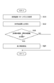
- FIG. 6 is a flowchart showing an intervention gain adjustment operation performed by the travel control device 1.
- the control process shown in FIG. 6 is executed after the control process shown in FIG. 2 and before the travel control process of S28 shown in FIG.
- FIG. 6 illustrates a case where travel control is performed using speed.
- the ECU 2 starts from a stable limit speed pattern input process (S30).
- the gain change determination unit 10 inputs the stable limit speed pattern generated by, for example, the control process shown in FIG.
- the process proceeds to actual speed input processing (S32).
- the gain change determination unit 10 inputs the actual vehicle speed. For example, the actual vehicle speed at the present time is input based on the detection result of the sensor 31.
- the process of S32 ends, the process proceeds to a speed determination process (S34).
- the gain change determination unit 10 determines whether or not the absolute value of the difference between the stability limit speed and the actual speed is greater than or equal to a predetermined value. For example, the gain change determination unit 10 calculates the stability limit speed at the current position from the stability limit speed pattern input in the process of S32. Then, the gain change determination unit 10 calculates a difference between the stability limit speed at the current position and the actual speed input in the process of S32, and determines whether or not the absolute value of the calculated difference is greater than or equal to a predetermined value. . In the process of S34, when the gain change determination unit 10 determines that the absolute value of the calculated difference is equal to or greater than a predetermined value, the process proceeds to a gain change process (S36).
- S36 gain change process
- the forced induction gain changing unit 11 changes the intervention gain used by the traveling control unit 22.
- the forced induction gain changing unit 11 changes the intervention gain so as to increase by changing the forced induction gain, for example.
- the induction gain changing unit 11 adjusts the intervention gain using the above-described equations 1 and 2.
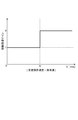
- the induction gain changing unit 11 changes the force induced gain G K using a map shown in FIG. Figure 7 is a map showing the forced induction gain G K which depends on the absolute value of the difference between the stable limit velocity and the actual velocity, indicates the predetermined value used in the processing step S34 as X.
- the forced induction gain change unit 11 changes the intervention gain greatly by setting the forced induction gain GK to Y (Y> 1).
- the intervention gain used by the traveling control unit 22 is not changed (S38).
- the induction gain changing unit 11 adjusts the intervention gain using the above-described equations 1 and 2, the induction gain changing unit 11 sets the forced induction gain GK to 1 as shown in FIG. .
- the control process shown in FIG. 6 ends.
- the driving control in which the driver's request is easily reflected that is, when the driver requests an acceleration
- the speed is controlled so as to follow the acceleration request.
- the actual speed may approach the limit speed
- the actual vehicle speed may exceed the stable limit speed at the position L1 as shown in P9.
- the intervention gain can be dynamically changed greatly when the actual speed approaches the stability limit speed by a predetermined value or more, so It becomes possible to strengthen the following. For this reason, as shown in P10, strong intervention control on the vehicle side is performed, and it can be avoided that the actual vehicle speed exceeds the stable limit speed at the position L1.
- the previous arbitration result exceeds the stability limit
- the gain change determination unit 10 acquires the stable limit speed pattern P1 indicating the upper limit speed that can travel without departing from the planned traveling road,
- the forced induction gain changing unit 11 adjusts the travel control performed using the target speed pattern P2 based on the stable limit speed pattern P1 and the actual speed. For this reason, for example, when traveling control is performed in which the actual speed is changed so as to be the target speed derived from the target speed pattern P2 that satisfies the driver's wishes, based on the stable limit speed pattern P1 and the actual speed. Travel control can be adjusted while evaluating the stability of travel.
- the actual vehicle speed exceeds the stability limit speed derived by the stability limit speed pattern P2 is sequentially verified, and when the actual vehicle speed is close to the stability limit speed, the stability is obtained by adjusting the travel control. Can be secured.
- the actual vehicle speed is controlled to be equal to or lower than the stable limit speed as traveling control during traveling. Therefore, the conventional travel control device only controls the actual vehicle speed to be 60 km / hr if the stability limit speed is 60 km / hr, and if the speed is 60 km / hr or less, the control result is 50 km. / Hr, 40 km / hr, 30 km / hr.
- the travel control apparatus 1 controls the target speed pattern P2 that satisfies the driver's wishes in a stable speed range by referring to the stability limit speed pattern P1.
- the stable limit speed pattern P1 can be dynamically used rather than only for generating the target speed pattern P2. Therefore, it becomes possible to satisfy the driving conditions desired by the user while ensuring the running stability.
- the degree to which the travel control intervenes can be changed depending on whether or not the driver's acceleration request is in a speed range that satisfies the travel stability. For this reason, it is possible to reduce the driver's uncomfortable feeling caused by the intervention control on the apparatus side in the speed range that satisfies the stability of traveling.
- the travel control device 1 according to the second embodiment is configured in substantially the same manner as the travel control device 1 according to the first embodiment, and is more stable than the travel control device 1 according to the first embodiment. Only map showing the forced induction gain G K which depends on the absolute value of the difference between the actual speed is different. In the second embodiment, the description of the same parts as those in the first embodiment will be omitted, and the differences will be mainly described.
- the configuration of the vehicle 5 including the travel control device 1 according to the present embodiment is the same as that of the vehicle 5 including the travel control device 1 according to the first embodiment.
- the traveling control device 1 according to the present embodiment is configured in the same manner as the traveling control device 1 according to the first embodiment, and only the map referred to by the forced induction gain changing unit 11 is different. Other functions are the same as those of the forced induction gain changing unit 11 according to the first embodiment.
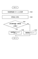
- FIG. 9 is a flowchart showing an intervention gain adjustment operation performed by the traveling control device 1 according to the second embodiment.
- the control process shown in FIG. 9 is executed, for example, after the execution of the control process shown in FIG. 2 and before the travel control process of S28 shown in FIG. Note that the stability limit speed pattern P1 and the target speed pattern P2 are generated by the control process shown in FIG. 2, and traveling control is performed by the control process shown in FIG. And in FIG. 9, the case where traveling control is performed using speed is demonstrated.
- the ECU 2 starts from a stable limit speed pattern input process (S40).
- S40 is the same as the process of S30.
- S42 the actual speed input process
- the gain change determination unit 10 inputs the actual vehicle speed.
- the process of S42 is the same as the process of S32.
- the process of S42 ends the process proceeds to a speed determination process (S44).
- the gain change determination unit 10 determines whether or not the absolute value of the difference between the stability limit speed and the actual speed is greater than or equal to a predetermined value.
- the process of S44 is the same as the process of S34.
- the process of S44 when the gain change determination unit 10 determines that the calculated absolute value of the difference is equal to or greater than a predetermined value, the process proceeds to a gain change process (S46).
- the forced induction gain changing unit 11 calculates the forced induction gain G K, to change the intervention gain using forced induction gain G K calculated.
- the induction gain changing unit 11 adjusts the intervention gain using the above-described equations 1 and 2.
- the induction gain changing unit 11 changes the force induced gain G K using a map shown in FIG. 10.
- Figure 10 is a map showing the forced induction gain G K which depends on the absolute value of the difference between the stable limit velocity and the actual velocity, indicates the predetermined value used in the processing at S44 as X.
- the forced induction gain changing unit 11 increases the absolute value of the difference between the stable limit velocity and the actual velocity is continuously increased to set the forced induction gain G K gradually.
- the intervention gain used by the traveling control unit 22 is not changed (S48).
- the induction gain changing unit 11 adjusts the intervention gain using the above-described equations 1 and 2, the induction gain changing unit 11 sets the forced induction gain GK to 1 as shown in FIG. .
- the control process shown in FIG. 9 ends.
- the intervention gain used in the travel control process of S28 shown in FIG. 4 depends on the difference between the actual vehicle speed and the stable limit vehicle speed. It is changed gradually. For this reason, when the actual vehicle speed approaches the stable limit vehicle speed, the vehicle control is continuously changed from the travel control in which the driver's request is easily reflected to the travel control in which the vehicle-side guidance is stronger.
- the degree of intervention in travel control can be gradually increased or decreased gradually according to the difference between the stable limit speed and the actual speed. That is, according to the travel control device 1 according to the second embodiment, it is possible to avoid a significant change in the intervention gain when the actual vehicle speed approaches the stability limit speed, while ensuring stable travel, It is possible to further reduce the driver's uncomfortable feeling caused by the intervention control on the device side.
- the predetermined value X for determining the change of the intervention gain can be set relatively flexibly, it is possible to prevent the intervention timing from being delayed decisively. For this reason, it is easy to realize the stability management, and it is possible to easily achieve both the driver's desire and the stability of the traveling.
- the travel control device 1 according to the third embodiment is configured in substantially the same manner as the travel control device 1 according to the first and second embodiments, and the travel control device 1 according to the first and second embodiments. Is different from the point that the traveling control is performed in anticipation of the future.
- the description of the same parts as those in the first and second embodiments is omitted, and the description will focus on the differences.
- the configuration of the vehicle 5 including the travel control device 1 according to the present embodiment is the same as that of the vehicle 5 including the travel control device 1 according to the first and second embodiments.
- the travel control device 1 according to the present embodiment is configured in substantially the same manner as the travel control device 1 according to the first and second embodiments, and includes a gain change determination unit (speed difference prediction unit) 10 and a forced induction gain change unit. Some of the 11 functions are different.
- the gain change determination unit 10 determines the future speed derived from the future speed and the stable limit speed pattern P1 when passing the future destination point on the planned travel path of the planned travel road. It has a function to predict the difference from the stability limit speed. For example, the gain change determination unit 10 sets the look-ahead time T pre for defining how much the predicted future is. For example, if the look-ahead time T pre is 5 seconds, the vehicle state when 5 seconds have elapsed is predicted.
- the gain change determination unit 10 assuming that the current velocity V x and the acceleration a x is constant until read-ahead time T pre elapses, the vehicle speed V pre and the position at the time of pre-reading time T pre elapsed (prefetch time T pre Estimate the distance L pre ) to move in. That is, the gain change determination unit 10 estimates the vehicle speed V pre and the position L pre when the look-ahead time T pre has elapsed, assuming that the vehicle 5 is in a uniform acceleration motion. The gain change determination unit 10 estimates the vehicle speed V pre and the position L pre using, for example, the following formulas 3 and 4.
- the forced induction gain changing unit 11 has a function of calculating a forced induction gain G pre based on a difference between a future speed and a future stable limit speed. For example, the forced induction gain changing unit 11 calculates the forced induction gain G pre using a map as in the first and second embodiments. Then, forced induction gain changing unit 11, first, when the forced induction gain G now forced induction gain G K obtained in the second embodiment, by comparing the forced induction gain G now and forced induction gain G pre And, it has a function of adopting a large forced induction gain among them so as to achieve traveling control that places importance on traveling stability. Other functions are the same as those of the forced induction gain changing unit 11 according to the first and second embodiments.
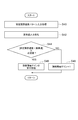
- FIG. 11 is a flowchart illustrating an intervention gain adjustment operation performed by the traveling control device 1 according to the third embodiment.
- the control process shown in FIG. 11 is executed after the execution of the control process shown in FIG. 2 and before the travel control process of S28 shown in FIG.
- the stability limit speed pattern P1 and the target speed pattern P2 are generated by the control process shown in FIG. 2, and traveling control is performed by the control process shown in FIG.
- the forced induction gain G now is generated using FIG. And in FIG. 11, the case where traveling control is performed using speed is demonstrated.
- the gain change determination unit 10 starts from the setting process of the prefetch time T pre (S50). In the process of S50, the gain change determination unit 10 sets a predetermined look-ahead time T pre . When the process of S50 ends, the process proceeds to a vehicle state estimation process (S52).
- the gain change determination unit 10 estimates the vehicle state when the prefetch time T pre has elapsed.
- the gain change determination unit 10 inputs the current actual vehicle speed V x , acceleration a x, and current position L2.
- the future vehicle speed V pre and the moving distance L pre are calculated using the above-described Expression 3 and Expression 4. For example, as shown in FIG. 12, it is assumed that a stable limit speed pattern P1 and a target speed pattern P2 are set, and the current position is L2. In this case, the gain change determination unit 10 calculates the future position L3 when the look-ahead time T pre has elapsed using the movement distance L pre .
- the routine proceeds to speed determination processing (S54).
- the gain change determination unit 10 determines whether or not the absolute value of the difference between the future stable limit speed Vs pre and the future actual speed V pre is greater than or equal to a predetermined value. As shown in FIG. 12, the gain change determination unit 10 uses the position L3 calculated in the processes of the stability limit speed patterns P1 and S52 to calculate the stability limit speed Vs pre when the prefetch time T pre has elapsed. Then, the gain change determination unit 10 determines whether or not the absolute value of the difference between the stability limit speed Vs pre and the future vehicle speed V pre calculated in S52 is equal to or greater than a predetermined value. In the process of S54, when the gain change determination unit 10 determines that the calculated absolute value of the difference is equal to or greater than a predetermined value, the process proceeds to a gain calculation process (S56).
- the forced induction gain changing unit 11 calculates a forced induction gain G pre based on the prefetch information.
- the induction gain changing unit 11 adjusts the intervention gain using the above-described equations 1 and 2.
- the induction gain changing unit 11 calculates the forced induction gain G pre using, for example, the map shown in FIG.
- the forced induction gain changing unit 11 compares the force induced gain G pre based on the current forced induction gain G now and look-ahead information, set the larger as a forced induction gain G K.
- the forced induction gain changing unit 11 compares the forced induction gain G now generated by the control process shown in FIG. 9 with the forced induction gain G pre calculated in the process of S56 (S58) and forces the larger one. set as an induction gain G K.
- the control process shown in FIG. 11 ends.
- the intervention gain used by the traveling control unit 22 is not changed (S58).
- the induction gain changing unit 11 adjusts the intervention gain using the above-described equations 1 and 2, the induction gain changing unit 11 sets the forced induction gain GK to 1 as shown in FIG. .
- the process step S58 proceeds to induce gain determination process (S60), sets the larger compared to the forced induction gain G now and forced induction gain G pre as a forced induction gain G K.
- the vehicle travels in the future using the difference between the future vehicle speed V pre and the future stable limit speed Vs pre derived from the stable limit speed pattern. It is possible to determine whether or not it is in a speed range that satisfies the stability of In this way, by making full use of the advantage of having the look-ahead information called the stable limit speed pattern, even when the stable limit speed changes suddenly due to, for example, a sudden change in curve radius, Can be avoided, and stable management can be easily realized. Therefore, it is possible to satisfy the driving conditions desired by the user while predicting and verifying the stability of the driving.
- embodiment mentioned above shows an example of the traveling control apparatus which concerns on this invention.
- the travel control device according to the present invention is not limited to the travel control device according to the embodiment, and the travel control device according to each embodiment may be modified or otherwise changed without changing the gist described in each claim. It may be applied to the above.
- the traveling control is performed using the speed pattern or the acceleration pattern
- the speed pattern may be changed to the acceleration pattern or the jerk pattern in the control using the speed pattern.
- the acceleration pattern may be replaced with the speed pattern or the jerk pattern.
- the calculation method of the stable limit speed pattern P1 has been described, but the present invention is not limited to this.
- the stable limit speed pattern P1 may be generated using only the road curvature, or may be generated using only the road shape. That is, the travel control device 1 according to the present embodiment can be effective regardless of the method for generating the stable limit speed pattern P1.
- the method for calculating the target speed pattern P2 has been described.
- the present invention is not limited to this.
- the target speed pattern P2 may be generated by another method, and it is not always necessary to generate the target speed pattern P2 after generating the stable limit speed pattern P1. That is, the travel control device 1 according to the present embodiment can achieve an effect regardless of the method for generating the target speed pattern P2.
Landscapes
- Engineering & Computer Science (AREA)
- Mechanical Engineering (AREA)
- Transportation (AREA)
- Chemical & Material Sciences (AREA)
- Combustion & Propulsion (AREA)
- Automation & Control Theory (AREA)
- General Engineering & Computer Science (AREA)
- Human Computer Interaction (AREA)
- Control Of Driving Devices And Active Controlling Of Vehicle (AREA)
- Traffic Control Systems (AREA)
Abstract
Description
本実施形態に係る走行制御装置は、車両の走行を制御する装置であって、例えば、追従運転や車線維持運転などの自動運転機能を備えた車両や、走行安定性を向上させる運転者支援システムを搭載した車両に好適に採用されるものである。


第2実施形態に係る走行制御装置1は、第1実施形態に係る走行制御装置1とほぼ同様に構成されるものであって、第1実施形態に係る走行制御装置1と比べ、安定限界速度と実速度との差分の絶対値に依存した強制誘導ゲインGKを示すマップのみが相違する。なお、第2実施形態においては、第1実施形態と重複する部分は説明を省略し、相違点を中心に説明する。
第3実施形態に係る走行制御装置1は、第1,第2実施形態に係る走行制御装置1とほぼ同様に構成されるものであって、第1,第2実施形態に係る走行制御装置1と比べ、将来を予測して走行制御を行う点が相違する。なお、第3実施形態においては、第1,第2実施形態と重複する部分は説明を省略し、相違点を中心に説明する。


Claims (5)
- 車両の走行を制御する走行制御装置であって、
前記車両が走行予定道路を逸脱することなく走行可能な上限速度を示す安定限界速度パターンを取得する取得部と、
前記安定限界速度パターン及び実速度に基づいて、目標速度を示す目標速度パターンを用いて行われる走行制御を調整する走行制御調整部と、
を備えることを特徴とする走行制御装置。 - 前記安定限界速度パターンは、前記走行予定道路の複数の道路曲率に基づいて生成され、
前記目標速度パターンは、前記安定限界速度パターン及び運転者の希望の運転条件を満たす理想速度パターンを用いて生成される請求項1に記載の走行制御装置。 - 前記走行制御調整部は、実速度と前記安定限界速度パターンから導出される上限速度との差分が所定値以上である場合と所定値未満である場合とで、走行制御が介入する程度を変更する請求項2に記載の走行制御装置。
- 前記走行制御調整部は、実速度と前記安定限界速度パターンから導出される上限速度との差分に応じて走行制御が介入する程度を連続的に変更する請求項3に記載の走行制御装置。
- 実速度に基づいて、前記走行予定道路の走行予定軌跡における将来の到達地点を通過する際の将来の速度と前記安定限界速度パターンから導出される将来の上限速度との差分を予測する速度差分予測部を備え、
前記走行制御調整部は、将来の速度と前記安定限界速度パターンから導出される将来の上限速度との差分が所定値以上である場合と所定値未満である場合とで、走行制御が介入する程度を変更する請求項1~4の何れか一項に記載の走行制御装置。
Priority Applications (5)
| Application Number | Priority Date | Filing Date | Title |
|---|---|---|---|
| US13/500,427 US9067571B2 (en) | 2009-12-18 | 2009-12-18 | Travel control device |
| JP2011545914A JP5168420B2 (ja) | 2009-12-18 | 2009-12-18 | 走行制御装置 |
| DE112009005449.8T DE112009005449B4 (de) | 2009-12-18 | 2009-12-18 | Fahrsteuervorrichtung |
| CN200980162687.6A CN102639378B (zh) | 2009-12-18 | 2009-12-18 | 行驶控制装置 |
| PCT/JP2009/071150 WO2011074115A1 (ja) | 2009-12-18 | 2009-12-18 | 走行制御装置 |
Applications Claiming Priority (1)
| Application Number | Priority Date | Filing Date | Title |
|---|---|---|---|
| PCT/JP2009/071150 WO2011074115A1 (ja) | 2009-12-18 | 2009-12-18 | 走行制御装置 |
Publications (1)
| Publication Number | Publication Date |
|---|---|
| WO2011074115A1 true WO2011074115A1 (ja) | 2011-06-23 |
Family
ID=44166904
Family Applications (1)
| Application Number | Title | Priority Date | Filing Date |
|---|---|---|---|
| PCT/JP2009/071150 Ceased WO2011074115A1 (ja) | 2009-12-18 | 2009-12-18 | 走行制御装置 |
Country Status (5)
| Country | Link |
|---|---|
| US (1) | US9067571B2 (ja) |
| JP (1) | JP5168420B2 (ja) |
| CN (1) | CN102639378B (ja) |
| DE (1) | DE112009005449B4 (ja) |
| WO (1) | WO2011074115A1 (ja) |
Cited By (8)
| Publication number | Priority date | Publication date | Assignee | Title |
|---|---|---|---|---|
| JP2014024409A (ja) * | 2012-07-25 | 2014-02-06 | Denso Corp | 車両用ブレーキ制御装置 |
| CN104670233A (zh) * | 2013-11-28 | 2015-06-03 | 现代摩比斯株式会社 | 车辆转弯控制方法及其装置 |
| JP2016053846A (ja) * | 2014-09-03 | 2016-04-14 | 株式会社デンソーアイティーラボラトリ | 自動運転支援システム、自動運転支援方法及び自動運転装置 |
| WO2016158341A1 (ja) * | 2015-03-27 | 2016-10-06 | 国立大学法人名古屋大学 | 運転支援装置 |
| CN109895627A (zh) * | 2019-02-25 | 2019-06-18 | 武汉理工大学 | 一种汽车油门踏板和汽车油门自动控制系统 |
| JP2020192942A (ja) * | 2019-05-30 | 2020-12-03 | 日産自動車株式会社 | 走行支援方法および走行支援装置 |
| JP2023101614A (ja) * | 2020-02-04 | 2023-07-21 | トヨタ自動車株式会社 | 車両制御装置、方法、プログラム、及び車両 |
| JP2023536071A (ja) * | 2020-07-24 | 2023-08-23 | ティーヴィーエス モーター カンパニー リミテッド | 電気機械式作動制御システム及びそのシステムを制御する方法 |
Families Citing this family (27)
| Publication number | Priority date | Publication date | Assignee | Title |
|---|---|---|---|---|
| WO2010100761A1 (ja) * | 2009-03-06 | 2010-09-10 | トヨタ自動車株式会社 | 車両走行制御装置 |
| JP2013246114A (ja) * | 2012-05-29 | 2013-12-09 | Sony Corp | 提示制御装置、提示制御方法、プログラム、記録媒体および位置取得装置 |
| DE102013200724A1 (de) * | 2013-01-18 | 2014-07-24 | Bayerische Motoren Werke Aktiengesellschaft | Vorhersage eines Fahrmanövers eines Fahrzeugs |
| US9096199B2 (en) * | 2013-10-09 | 2015-08-04 | Ford Global Technologies, Llc | Monitoring autonomous vehicle braking |
| EP2887018B1 (en) * | 2013-12-18 | 2018-02-07 | Harman Becker Automotive Systems GmbH | Method and system for providing fueling cost information in a vehicle |
| SE539778C2 (sv) * | 2014-05-21 | 2017-11-28 | Scania Cv Ab | Förfarande och system för anpassning av ett fordons framförande på en vägbana i samband med kurvkörning |
| GB2526346B (en) * | 2014-05-22 | 2018-01-03 | Jaguar Land Rover Ltd | Vehicle speed control system and method |
| US10589751B2 (en) | 2014-12-31 | 2020-03-17 | Robert Bosch Gmbh | Autonomous maneuver notification for autonomous vehicles |
| JP6418062B2 (ja) * | 2015-05-19 | 2018-11-07 | トヨタ自動車株式会社 | 車速制御装置及び車両 |
| US10183684B2 (en) * | 2016-03-31 | 2019-01-22 | General Electric Company | Multiple vehicle control system |
| DE102016212055A1 (de) * | 2016-07-01 | 2018-01-04 | Continental Automotive Gmbh | System zum automatisierten Fahren eines Fahrzeugs |
| JP6662316B2 (ja) | 2017-01-17 | 2020-03-11 | トヨタ自動車株式会社 | 車両制御システム |
| JP6907896B2 (ja) | 2017-11-17 | 2021-07-21 | トヨタ自動車株式会社 | 自動運転システム |
| CN108791295A (zh) * | 2018-06-05 | 2018-11-13 | 北京智行者科技有限公司 | 车辆驾驶数据处理方法及终端 |
| DE102018213471A1 (de) * | 2018-08-10 | 2020-02-13 | Bayerische Motoren Werke Aktiengesellschaft | Begrenzen eines Soll-Werts für eine Steuergröße eines Fahrerassistenzsystems |
| US11392127B2 (en) * | 2018-10-15 | 2022-07-19 | Zoox, Inc. | Trajectory initialization |
| JP2020095594A (ja) | 2018-12-14 | 2020-06-18 | トヨタ自動車株式会社 | 車両制御装置及び車両制御方法 |
| JP7215392B2 (ja) | 2019-10-15 | 2023-01-31 | トヨタ自動車株式会社 | 車両制御システム |
| CN114312746B (zh) * | 2020-09-29 | 2024-08-06 | 奥迪股份公司 | 辅助驾驶装置以及相应的车辆、方法、计算机设备和介质 |
| DE102020133160B4 (de) | 2020-12-11 | 2025-03-13 | Automotive Research & Testing Center | Dynamische Geschwindigkeitsplanungsmethode für autonomes Fahrzeug und entsprechendes System |
| US12110019B2 (en) * | 2021-01-11 | 2024-10-08 | Hyundai Mobis Co., Ltd. | Vehicle driving control system and method |
| CN113147773B (zh) * | 2021-02-20 | 2022-12-02 | 京东鲲鹏(江苏)科技有限公司 | 一种无人车速度控制方法、装置、无人车及存储介质 |
| JP7548184B2 (ja) * | 2021-10-07 | 2024-09-10 | トヨタ自動車株式会社 | 走行速度制御装置およびこれを搭載する車両 |
| JP7632236B2 (ja) | 2021-11-04 | 2025-02-19 | トヨタ自動車株式会社 | 車両制御システム及び車両制御方法 |
| JP7622714B2 (ja) | 2022-08-23 | 2025-01-28 | トヨタ自動車株式会社 | 運転支援装置、運転支援方法 |
| JP7790323B2 (ja) | 2022-11-15 | 2025-12-23 | トヨタ自動車株式会社 | 車両制御装置 |
| JP7831405B2 (ja) | 2023-06-06 | 2026-03-17 | トヨタ自動車株式会社 | 車両制御装置、及び車両制御方法 |
Citations (3)
| Publication number | Priority date | Publication date | Assignee | Title |
|---|---|---|---|---|
| JP2006123586A (ja) * | 2004-10-26 | 2006-05-18 | Honda Motor Co Ltd | 定速走行制御装置を具備する車両の走行安全装置 |
| JP2008074232A (ja) * | 2006-09-21 | 2008-04-03 | Nissan Motor Co Ltd | 車両用運転支援装置および方法 |
| JP2008195226A (ja) * | 2007-02-13 | 2008-08-28 | Toyota Motor Corp | 車両用走行制御装置 |
Family Cites Families (20)
| Publication number | Priority date | Publication date | Assignee | Title |
|---|---|---|---|---|
| JP3139811B2 (ja) * | 1992-02-28 | 2001-03-05 | 株式会社日立製作所 | エンジン制御装置 |
| JP3351205B2 (ja) | 1995-11-09 | 2002-11-25 | 株式会社日立製作所 | 車両の安全走行制御装置及び制御方法 |
| US6412533B1 (en) * | 1997-12-29 | 2002-07-02 | Pirelli Pneumatici S.P.A. | High transverse-curvature tire for two-wheeled vehicles including specified belt structure |
| JP4085500B2 (ja) * | 1999-01-29 | 2008-05-14 | 株式会社エクォス・リサーチ | 車両状況把握装置、エージェント装置、および、車両制御装置 |
| JP3482166B2 (ja) * | 1999-12-08 | 2003-12-22 | 本田技研工業株式会社 | 車両用運転状況監視装置 |
| JP4707877B2 (ja) * | 2001-06-11 | 2011-06-22 | パイオニア株式会社 | ドライブ候補地提示装置及び方法、ナビゲーション装置及びコンピュータプログラム |
| KR20060049706A (ko) * | 2004-07-20 | 2006-05-19 | 아이신세이끼가부시끼가이샤 | 차량의 레인주행지원장치 |
| US20070010941A1 (en) * | 2005-07-07 | 2007-01-11 | Marsh David C | Land navigation system |
| US7400963B2 (en) | 2005-12-09 | 2008-07-15 | Gm Global Technology Operations, Inc. | Speed control method for vehicle approaching and traveling on a curve |
| JP2007187090A (ja) | 2006-01-13 | 2007-07-26 | Toyota Motor Corp | 速度維持制御装置 |
| JP4169065B2 (ja) | 2006-02-13 | 2008-10-22 | 株式会社デンソー | 車両制御装置 |
| JP2008012975A (ja) * | 2006-07-04 | 2008-01-24 | Xanavi Informatics Corp | 車両走行制御システム |
| US8165771B2 (en) * | 2006-08-31 | 2012-04-24 | Kabushikikaisha Equos Research | Vehicle |
| JP4525670B2 (ja) | 2006-11-20 | 2010-08-18 | トヨタ自動車株式会社 | 走行制御計画生成システム |
| US7774121B2 (en) | 2007-07-31 | 2010-08-10 | Gm Global Technology Operations, Inc. | Curve speed control system with adaptive map preview time and driving mode selection |
| JP5157304B2 (ja) * | 2007-08-03 | 2013-03-06 | 日産自動車株式会社 | 車両用走行制御装置 |
| US8116972B2 (en) * | 2008-02-08 | 2012-02-14 | Ford Global Technologies, Llc | System and method for determining a vehicle refueling strategy |
| EP2151808A1 (en) * | 2008-08-07 | 2010-02-10 | Aisin Aw Co., Ltd. | Safe driving evaluation system and safe driving evaluation method |
| CN102414048A (zh) * | 2009-04-23 | 2012-04-11 | 丰田自动车株式会社 | 驾驶不当应对装置 |
| US9140568B2 (en) * | 2010-09-20 | 2015-09-22 | Garmin Switzerland Gmbh | Multi-screen vehicle system |
-
2009
- 2009-12-18 US US13/500,427 patent/US9067571B2/en active Active
- 2009-12-18 DE DE112009005449.8T patent/DE112009005449B4/de active Active
- 2009-12-18 CN CN200980162687.6A patent/CN102639378B/zh not_active Expired - Fee Related
- 2009-12-18 JP JP2011545914A patent/JP5168420B2/ja active Active
- 2009-12-18 WO PCT/JP2009/071150 patent/WO2011074115A1/ja not_active Ceased
Patent Citations (3)
| Publication number | Priority date | Publication date | Assignee | Title |
|---|---|---|---|---|
| JP2006123586A (ja) * | 2004-10-26 | 2006-05-18 | Honda Motor Co Ltd | 定速走行制御装置を具備する車両の走行安全装置 |
| JP2008074232A (ja) * | 2006-09-21 | 2008-04-03 | Nissan Motor Co Ltd | 車両用運転支援装置および方法 |
| JP2008195226A (ja) * | 2007-02-13 | 2008-08-28 | Toyota Motor Corp | 車両用走行制御装置 |
Cited By (12)
| Publication number | Priority date | Publication date | Assignee | Title |
|---|---|---|---|---|
| JP2014024409A (ja) * | 2012-07-25 | 2014-02-06 | Denso Corp | 車両用ブレーキ制御装置 |
| CN104670233A (zh) * | 2013-11-28 | 2015-06-03 | 现代摩比斯株式会社 | 车辆转弯控制方法及其装置 |
| JP2016053846A (ja) * | 2014-09-03 | 2016-04-14 | 株式会社デンソーアイティーラボラトリ | 自動運転支援システム、自動運転支援方法及び自動運転装置 |
| WO2016158341A1 (ja) * | 2015-03-27 | 2016-10-06 | 国立大学法人名古屋大学 | 運転支援装置 |
| JP2016186683A (ja) * | 2015-03-27 | 2016-10-27 | 国立大学法人名古屋大学 | 運転支援装置 |
| CN109895627A (zh) * | 2019-02-25 | 2019-06-18 | 武汉理工大学 | 一种汽车油门踏板和汽车油门自动控制系统 |
| CN109895627B (zh) * | 2019-02-25 | 2020-07-31 | 武汉理工大学 | 一种汽车油门踏板和汽车油门自动控制系统 |
| JP2020192942A (ja) * | 2019-05-30 | 2020-12-03 | 日産自動車株式会社 | 走行支援方法および走行支援装置 |
| JP7208106B2 (ja) | 2019-05-30 | 2023-01-18 | 日産自動車株式会社 | 走行支援方法および走行支援装置 |
| JP2023101614A (ja) * | 2020-02-04 | 2023-07-21 | トヨタ自動車株式会社 | 車両制御装置、方法、プログラム、及び車両 |
| JP7571817B2 (ja) | 2020-02-04 | 2024-10-23 | トヨタ自動車株式会社 | 車両制御装置、方法、プログラム、及び車両 |
| JP2023536071A (ja) * | 2020-07-24 | 2023-08-23 | ティーヴィーエス モーター カンパニー リミテッド | 電気機械式作動制御システム及びそのシステムを制御する方法 |
Also Published As
| Publication number | Publication date |
|---|---|
| JP5168420B2 (ja) | 2013-03-21 |
| CN102639378B (zh) | 2016-01-13 |
| US9067571B2 (en) | 2015-06-30 |
| DE112009005449T5 (de) | 2013-04-04 |
| JPWO2011074115A1 (ja) | 2013-04-25 |
| DE112009005449B4 (de) | 2022-02-24 |
| US20120203440A1 (en) | 2012-08-09 |
| CN102639378A (zh) | 2012-08-15 |
Similar Documents
| Publication | Publication Date | Title |
|---|---|---|
| JP5168420B2 (ja) | 走行制御装置 | |
| US8483949B2 (en) | Running pattern calculating apparatus and running pattern calculating method | |
| JP5417386B2 (ja) | 車両運動制御装置 | |
| JP5392202B2 (ja) | 車両の制御装置 | |
| JP4466716B2 (ja) | 走行軌跡生成方法及び走行軌跡生成装置 | |
| JP4497231B2 (ja) | 車両用速度制御装置 | |
| JP5168421B2 (ja) | 運転支援装置 | |
| JP7077870B2 (ja) | 自動運転システム | |
| JP2019123377A (ja) | 車両制御装置 | |
| JP2006513903A (ja) | 車両の速度を制御する方法 | |
| CN113348121A (zh) | 用于操作自适应速度调节器的方法和控制单元 | |
| EP2470406B1 (en) | System and method for maintaining driving times | |
| JP2012144160A (ja) | 運転支援装置 | |
| JP5029377B2 (ja) | 走行軌跡生成装置及び走行軌跡生成方法 | |
| WO2018225493A1 (ja) | 車両運動制御装置 | |
| JP4285330B2 (ja) | 車両運動制御システム | |
| JP4239809B2 (ja) | 車両用運転支援装置 | |
| JP4941240B2 (ja) | 走行軌跡生成方法及び走行軌跡生成装置 | |
| JP4710625B2 (ja) | 車両用駆動力制御装置 | |
| JP7669873B2 (ja) | 駆動力制御方法及び駆動力制御装置 | |
| JP2011000952A (ja) | 運転支援装置 | |
| JP4617995B2 (ja) | 車両用駆動力制御装置 | |
| JP2023135259A (ja) | 移動体制御システム、及び移動体制御方法 | |
| JP2007313925A (ja) | 車両用駆動力制御装置 | |
| CN118284549A (zh) | 用于机动车的自动纵向引导的方法和装置 |
Legal Events
| Date | Code | Title | Description |
|---|---|---|---|
| WWE | Wipo information: entry into national phase |
Ref document number: 200980162687.6 Country of ref document: CN |
|
| 121 | Ep: the epo has been informed by wipo that ep was designated in this application |
Ref document number: 09852306 Country of ref document: EP Kind code of ref document: A1 |
|
| WWE | Wipo information: entry into national phase |
Ref document number: 2011545914 Country of ref document: JP |
|
| WWE | Wipo information: entry into national phase |
Ref document number: 13500427 Country of ref document: US |
|
| WWE | Wipo information: entry into national phase |
Ref document number: 1120090054498 Country of ref document: DE Ref document number: 112009005449 Country of ref document: DE |
|
| 122 | Ep: pct application non-entry in european phase |
Ref document number: 09852306 Country of ref document: EP Kind code of ref document: A1 |