WO2016158341A1 - 運転支援装置 - Google Patents
運転支援装置 Download PDFInfo
- Publication number
- WO2016158341A1 WO2016158341A1 PCT/JP2016/057927 JP2016057927W WO2016158341A1 WO 2016158341 A1 WO2016158341 A1 WO 2016158341A1 JP 2016057927 W JP2016057927 W JP 2016057927W WO 2016158341 A1 WO2016158341 A1 WO 2016158341A1
- Authority
- WO
- WIPO (PCT)
- Prior art keywords
- vehicle
- driving
- intervention
- behavior
- support device
- Prior art date
Links
- 238000004364 calculation method Methods 0.000 claims abstract description 19
- 230000001133 acceleration Effects 0.000 claims description 5
- 230000003542 behavioural effect Effects 0.000 abstract 3
- 230000006399 behavior Effects 0.000 abstract 2
- 238000000034 method Methods 0.000 description 28
- 238000005457 optimization Methods 0.000 description 10
- 238000010586 diagram Methods 0.000 description 9
- 230000009471 action Effects 0.000 description 8
- 238000001514 detection method Methods 0.000 description 7
- 230000008569 process Effects 0.000 description 6
- 230000007704 transition Effects 0.000 description 6
- 238000005516 engineering process Methods 0.000 description 5
- 230000004048 modification Effects 0.000 description 4
- 238000012986 modification Methods 0.000 description 4
- 238000004590 computer program Methods 0.000 description 2
- 238000011156 evaluation Methods 0.000 description 2
- 230000002123 temporal effect Effects 0.000 description 2
- 230000008859 change Effects 0.000 description 1
- 239000006185 dispersion Substances 0.000 description 1
- 230000014509 gene expression Effects 0.000 description 1
- 230000005484 gravity Effects 0.000 description 1
- 230000006872 improvement Effects 0.000 description 1
- 230000009467 reduction Effects 0.000 description 1
- 230000000638 stimulation Effects 0.000 description 1
Images


Classifications
-
- B—PERFORMING OPERATIONS; TRANSPORTING
- B60—VEHICLES IN GENERAL
- B60W—CONJOINT CONTROL OF VEHICLE SUB-UNITS OF DIFFERENT TYPE OR DIFFERENT FUNCTION; CONTROL SYSTEMS SPECIALLY ADAPTED FOR HYBRID VEHICLES; ROAD VEHICLE DRIVE CONTROL SYSTEMS FOR PURPOSES NOT RELATED TO THE CONTROL OF A PARTICULAR SUB-UNIT
- B60W30/00—Purposes of road vehicle drive control systems not related to the control of a particular sub-unit, e.g. of systems using conjoint control of vehicle sub-units, or advanced driver assistance systems for ensuring comfort, stability and safety or drive control systems for propelling or retarding the vehicle
- B60W30/08—Active safety systems predicting or avoiding probable or impending collision or attempting to minimise its consequences
- B60W30/09—Taking automatic action to avoid collision, e.g. braking and steering
-
- B—PERFORMING OPERATIONS; TRANSPORTING
- B60—VEHICLES IN GENERAL
- B60W—CONJOINT CONTROL OF VEHICLE SUB-UNITS OF DIFFERENT TYPE OR DIFFERENT FUNCTION; CONTROL SYSTEMS SPECIALLY ADAPTED FOR HYBRID VEHICLES; ROAD VEHICLE DRIVE CONTROL SYSTEMS FOR PURPOSES NOT RELATED TO THE CONTROL OF A PARTICULAR SUB-UNIT
- B60W30/00—Purposes of road vehicle drive control systems not related to the control of a particular sub-unit, e.g. of systems using conjoint control of vehicle sub-units, or advanced driver assistance systems for ensuring comfort, stability and safety or drive control systems for propelling or retarding the vehicle
- B60W30/08—Active safety systems predicting or avoiding probable or impending collision or attempting to minimise its consequences
- B60W30/095—Predicting travel path or likelihood of collision
- B60W30/0953—Predicting travel path or likelihood of collision the prediction being responsive to vehicle dynamic parameters
-
- B—PERFORMING OPERATIONS; TRANSPORTING
- B60—VEHICLES IN GENERAL
- B60W—CONJOINT CONTROL OF VEHICLE SUB-UNITS OF DIFFERENT TYPE OR DIFFERENT FUNCTION; CONTROL SYSTEMS SPECIALLY ADAPTED FOR HYBRID VEHICLES; ROAD VEHICLE DRIVE CONTROL SYSTEMS FOR PURPOSES NOT RELATED TO THE CONTROL OF A PARTICULAR SUB-UNIT
- B60W30/00—Purposes of road vehicle drive control systems not related to the control of a particular sub-unit, e.g. of systems using conjoint control of vehicle sub-units, or advanced driver assistance systems for ensuring comfort, stability and safety or drive control systems for propelling or retarding the vehicle
- B60W30/08—Active safety systems predicting or avoiding probable or impending collision or attempting to minimise its consequences
- B60W30/095—Predicting travel path or likelihood of collision
- B60W30/0956—Predicting travel path or likelihood of collision the prediction being responsive to traffic or environmental parameters
-
- B—PERFORMING OPERATIONS; TRANSPORTING
- B60—VEHICLES IN GENERAL
- B60W—CONJOINT CONTROL OF VEHICLE SUB-UNITS OF DIFFERENT TYPE OR DIFFERENT FUNCTION; CONTROL SYSTEMS SPECIALLY ADAPTED FOR HYBRID VEHICLES; ROAD VEHICLE DRIVE CONTROL SYSTEMS FOR PURPOSES NOT RELATED TO THE CONTROL OF A PARTICULAR SUB-UNIT
- B60W30/00—Purposes of road vehicle drive control systems not related to the control of a particular sub-unit, e.g. of systems using conjoint control of vehicle sub-units, or advanced driver assistance systems for ensuring comfort, stability and safety or drive control systems for propelling or retarding the vehicle
- B60W30/14—Adaptive cruise control
-
- B—PERFORMING OPERATIONS; TRANSPORTING
- B60—VEHICLES IN GENERAL
- B60W—CONJOINT CONTROL OF VEHICLE SUB-UNITS OF DIFFERENT TYPE OR DIFFERENT FUNCTION; CONTROL SYSTEMS SPECIALLY ADAPTED FOR HYBRID VEHICLES; ROAD VEHICLE DRIVE CONTROL SYSTEMS FOR PURPOSES NOT RELATED TO THE CONTROL OF A PARTICULAR SUB-UNIT
- B60W40/00—Estimation or calculation of non-directly measurable driving parameters for road vehicle drive control systems not related to the control of a particular sub unit, e.g. by using mathematical models
- B60W40/08—Estimation or calculation of non-directly measurable driving parameters for road vehicle drive control systems not related to the control of a particular sub unit, e.g. by using mathematical models related to drivers or passengers
- B60W40/09—Driving style or behaviour
-
- B—PERFORMING OPERATIONS; TRANSPORTING
- B60—VEHICLES IN GENERAL
- B60W—CONJOINT CONTROL OF VEHICLE SUB-UNITS OF DIFFERENT TYPE OR DIFFERENT FUNCTION; CONTROL SYSTEMS SPECIALLY ADAPTED FOR HYBRID VEHICLES; ROAD VEHICLE DRIVE CONTROL SYSTEMS FOR PURPOSES NOT RELATED TO THE CONTROL OF A PARTICULAR SUB-UNIT
- B60W50/00—Details of control systems for road vehicle drive control not related to the control of a particular sub-unit, e.g. process diagnostic or vehicle driver interfaces
- B60W50/08—Interaction between the driver and the control system
- B60W50/085—Changing the parameters of the control units, e.g. changing limit values, working points by control input
-
- B—PERFORMING OPERATIONS; TRANSPORTING
- B62—LAND VEHICLES FOR TRAVELLING OTHERWISE THAN ON RAILS
- B62D—MOTOR VEHICLES; TRAILERS
- B62D6/00—Arrangements for automatically controlling steering depending on driving conditions sensed and responded to, e.g. control circuits
-
- G—PHYSICS
- G08—SIGNALLING
- G08G—TRAFFIC CONTROL SYSTEMS
- G08G1/00—Traffic control systems for road vehicles
- G08G1/16—Anti-collision systems
-
- B—PERFORMING OPERATIONS; TRANSPORTING
- B60—VEHICLES IN GENERAL
- B60W—CONJOINT CONTROL OF VEHICLE SUB-UNITS OF DIFFERENT TYPE OR DIFFERENT FUNCTION; CONTROL SYSTEMS SPECIALLY ADAPTED FOR HYBRID VEHICLES; ROAD VEHICLE DRIVE CONTROL SYSTEMS FOR PURPOSES NOT RELATED TO THE CONTROL OF A PARTICULAR SUB-UNIT
- B60W2420/00—Indexing codes relating to the type of sensors based on the principle of their operation
- B60W2420/40—Photo or light sensitive means, e.g. infrared sensors
- B60W2420/403—Image sensing, e.g. optical camera
-
- B60W2420/408—
-
- B—PERFORMING OPERATIONS; TRANSPORTING
- B60—VEHICLES IN GENERAL
- B60W—CONJOINT CONTROL OF VEHICLE SUB-UNITS OF DIFFERENT TYPE OR DIFFERENT FUNCTION; CONTROL SYSTEMS SPECIALLY ADAPTED FOR HYBRID VEHICLES; ROAD VEHICLE DRIVE CONTROL SYSTEMS FOR PURPOSES NOT RELATED TO THE CONTROL OF A PARTICULAR SUB-UNIT
- B60W2520/00—Input parameters relating to overall vehicle dynamics
- B60W2520/10—Longitudinal speed
-
- B—PERFORMING OPERATIONS; TRANSPORTING
- B60—VEHICLES IN GENERAL
- B60W—CONJOINT CONTROL OF VEHICLE SUB-UNITS OF DIFFERENT TYPE OR DIFFERENT FUNCTION; CONTROL SYSTEMS SPECIALLY ADAPTED FOR HYBRID VEHICLES; ROAD VEHICLE DRIVE CONTROL SYSTEMS FOR PURPOSES NOT RELATED TO THE CONTROL OF A PARTICULAR SUB-UNIT
- B60W2520/00—Input parameters relating to overall vehicle dynamics
- B60W2520/14—Yaw
-
- B—PERFORMING OPERATIONS; TRANSPORTING
- B60—VEHICLES IN GENERAL
- B60W—CONJOINT CONTROL OF VEHICLE SUB-UNITS OF DIFFERENT TYPE OR DIFFERENT FUNCTION; CONTROL SYSTEMS SPECIALLY ADAPTED FOR HYBRID VEHICLES; ROAD VEHICLE DRIVE CONTROL SYSTEMS FOR PURPOSES NOT RELATED TO THE CONTROL OF A PARTICULAR SUB-UNIT
- B60W2540/00—Input parameters relating to occupants
- B60W2540/10—Accelerator pedal position
-
- B—PERFORMING OPERATIONS; TRANSPORTING
- B60—VEHICLES IN GENERAL
- B60W—CONJOINT CONTROL OF VEHICLE SUB-UNITS OF DIFFERENT TYPE OR DIFFERENT FUNCTION; CONTROL SYSTEMS SPECIALLY ADAPTED FOR HYBRID VEHICLES; ROAD VEHICLE DRIVE CONTROL SYSTEMS FOR PURPOSES NOT RELATED TO THE CONTROL OF A PARTICULAR SUB-UNIT
- B60W2540/00—Input parameters relating to occupants
- B60W2540/12—Brake pedal position
-
- B—PERFORMING OPERATIONS; TRANSPORTING
- B60—VEHICLES IN GENERAL
- B60W—CONJOINT CONTROL OF VEHICLE SUB-UNITS OF DIFFERENT TYPE OR DIFFERENT FUNCTION; CONTROL SYSTEMS SPECIALLY ADAPTED FOR HYBRID VEHICLES; ROAD VEHICLE DRIVE CONTROL SYSTEMS FOR PURPOSES NOT RELATED TO THE CONTROL OF A PARTICULAR SUB-UNIT
- B60W2540/00—Input parameters relating to occupants
- B60W2540/18—Steering angle
-
- B—PERFORMING OPERATIONS; TRANSPORTING
- B60—VEHICLES IN GENERAL
- B60W—CONJOINT CONTROL OF VEHICLE SUB-UNITS OF DIFFERENT TYPE OR DIFFERENT FUNCTION; CONTROL SYSTEMS SPECIALLY ADAPTED FOR HYBRID VEHICLES; ROAD VEHICLE DRIVE CONTROL SYSTEMS FOR PURPOSES NOT RELATED TO THE CONTROL OF A PARTICULAR SUB-UNIT
- B60W2540/00—Input parameters relating to occupants
- B60W2540/30—Driving style
-
- B—PERFORMING OPERATIONS; TRANSPORTING
- B60—VEHICLES IN GENERAL
- B60W—CONJOINT CONTROL OF VEHICLE SUB-UNITS OF DIFFERENT TYPE OR DIFFERENT FUNCTION; CONTROL SYSTEMS SPECIALLY ADAPTED FOR HYBRID VEHICLES; ROAD VEHICLE DRIVE CONTROL SYSTEMS FOR PURPOSES NOT RELATED TO THE CONTROL OF A PARTICULAR SUB-UNIT
- B60W2552/00—Input parameters relating to infrastructure
- B60W2552/53—Road markings, e.g. lane marker or crosswalk
-
- B—PERFORMING OPERATIONS; TRANSPORTING
- B60—VEHICLES IN GENERAL
- B60W—CONJOINT CONTROL OF VEHICLE SUB-UNITS OF DIFFERENT TYPE OR DIFFERENT FUNCTION; CONTROL SYSTEMS SPECIALLY ADAPTED FOR HYBRID VEHICLES; ROAD VEHICLE DRIVE CONTROL SYSTEMS FOR PURPOSES NOT RELATED TO THE CONTROL OF A PARTICULAR SUB-UNIT
- B60W2554/00—Input parameters relating to objects
- B60W2554/20—Static objects
-
- B—PERFORMING OPERATIONS; TRANSPORTING
- B60—VEHICLES IN GENERAL
- B60W—CONJOINT CONTROL OF VEHICLE SUB-UNITS OF DIFFERENT TYPE OR DIFFERENT FUNCTION; CONTROL SYSTEMS SPECIALLY ADAPTED FOR HYBRID VEHICLES; ROAD VEHICLE DRIVE CONTROL SYSTEMS FOR PURPOSES NOT RELATED TO THE CONTROL OF A PARTICULAR SUB-UNIT
- B60W2554/00—Input parameters relating to objects
- B60W2554/40—Dynamic objects, e.g. animals, windblown objects
- B60W2554/402—Type
- B60W2554/4029—Pedestrians
-
- B—PERFORMING OPERATIONS; TRANSPORTING
- B60—VEHICLES IN GENERAL
- B60W—CONJOINT CONTROL OF VEHICLE SUB-UNITS OF DIFFERENT TYPE OR DIFFERENT FUNCTION; CONTROL SYSTEMS SPECIALLY ADAPTED FOR HYBRID VEHICLES; ROAD VEHICLE DRIVE CONTROL SYSTEMS FOR PURPOSES NOT RELATED TO THE CONTROL OF A PARTICULAR SUB-UNIT
- B60W2554/00—Input parameters relating to objects
- B60W2554/40—Dynamic objects, e.g. animals, windblown objects
- B60W2554/404—Characteristics
- B60W2554/4041—Position
-
- G—PHYSICS
- G08—SIGNALLING
- G08G—TRAFFIC CONTROL SYSTEMS
- G08G1/00—Traffic control systems for road vehicles
- G08G1/16—Anti-collision systems
- G08G1/165—Anti-collision systems for passive traffic, e.g. including static obstacles, trees
-
- G—PHYSICS
- G08—SIGNALLING
- G08G—TRAFFIC CONTROL SYSTEMS
- G08G1/00—Traffic control systems for road vehicles
- G08G1/16—Anti-collision systems
- G08G1/166—Anti-collision systems for active traffic, e.g. moving vehicles, pedestrians, bikes
Definitions
- the technology disclosed in this specification relates to a driving support device.
- Driving that intervenes in the operation of the driver for steering and braking of the vehicle in order to prevent the vehicle from colliding with obstacles, etc. or to secure the safety of the vehicle by stopping the vehicle at a predetermined position
- Support devices are known.
- the driving support device is required to reduce the driver's uncomfortable feeling due to the operation intervention as much as possible while ensuring safety.
- multiple trajectories that a vehicle can take when operation intervention is performed are calculated, and if the number of trajectories that do not overlap with the area where the obstacle exists exceeds a predetermined number, priority is given to reducing the sense of incongruity.
- the conventional driving support apparatus has room for improvement in terms of both ensuring safety and reducing discomfort.
- a driving support device disclosed in the present specification is a driving support device that performs an intervention for a predetermined operation of a vehicle, and includes a region setting unit that sets a predetermined region that is a region related to the behavior of the vehicle, In order to acquire driving behavior characteristic information indicating the driving behavior characteristics of the driver of the vehicle, and the behavior of the vehicle predicted using the acquired driving behavior characteristic information falls within the predetermined region over a predetermined prediction section
- a permissible control input range calculation unit that calculates a permissible control input range that is a range of the operation permitted at the current time, and a determination unit that determines whether or not the operation at the current time is within the permissible control input range.
- An operation intervention execution unit that executes the intervention when it is determined that the operation at the current time is outside the allowable control input range. According to this driving support device, while ensuring safety by operating intervention, by using driving behavior characteristic information for vehicle behavior prediction for calculating allowable control input range, it is possible to perform operation intervention by a uniform judgment method. Compared with the conventional configuration for determining whether or not to execute, the driver's uncomfortable feeling due to the operation intervention can be further reduced.
- the area setting unit acquires specific driving action information that is the driving action characteristic information of a specific driver, and uses the acquired specific driving action information to determine the predetermined area. It is good also as a structure to set. According to this driving support apparatus, the driver can be guided to a specific driving action (for example, a driving action to be exemplified) by the operation intervention, and safety can be more reliably achieved.
- a specific driving action for example, a driving action to be exemplified
- behavior information indicating the behavior of the vehicle is accumulated in association with the driver of the vehicle while the vehicle is traveling, and the driving behavior is stored using the accumulated behavior information. It is good also as a structure provided with the driving action characteristic information management part which produces
- the allowable control input range calculation unit acquires vehicle characteristic information indicating a movement characteristic of the vehicle, and uses the driving behavior characteristic information and the vehicle characteristic information to perform the behavior of the vehicle. It is good also as a structure which predicts. According to the present driving assistance device, it is possible to predict an appropriate behavior in consideration of the motion characteristics of the vehicle, and it is possible to achieve both ensuring safety and reducing discomfort at a high level.
- the driving assistance device may further include an intervention assistance input determining unit that variably determines the degree of intervention. According to this driving support apparatus, it is possible to perform the operation intervention with an appropriate degree of intervention according to the driving ability of the driver.
- the operation may be a steering operation, and the behavior of the vehicle may include a track taken by the vehicle. According to the present driving support device, it is possible to further reduce the driver's uncomfortable feeling due to the operation intervention regarding the steering operation.
- the operation may be at least one of a braking operation and an acceleration operation, and the behavior of the vehicle may include a speed of the vehicle. According to this driving support apparatus, the driver's uncomfortable feeling due to the operation intervention on at least one of braking and acceleration can be further reduced.
- the allowable control input range calculation unit may be configured to predict the behavior of the vehicle when the intervention is not executed. According to this driving support device, it is possible to perform behavior prediction with higher accuracy than behavior prediction when operation intervention is executed, and as a result, it is possible to accurately determine whether or not operation intervention can be performed.
- the technology disclosed in the present specification can be realized in various forms.
- the driving support device the vehicle including the driving support device, the driving support method, the vehicle control method, and the methods thereof.
- the present invention can be realized in the form of a computer program to be realized, a non-temporary recording medium on which the computer program is recorded, or the like.
- FIG. 10 It is explanatory drawing which shows schematic structure of the vehicle 10 in this embodiment. It is explanatory drawing which shows the outline
- 2 is an explanatory diagram illustrating an example of a traveling environment of the vehicle 10.
- FIG. It is explanatory drawing which shows an example of a driver
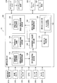
- FIG. 1 is an explanatory diagram showing a schematic configuration of a vehicle 10 in the present embodiment.
- the vehicle 10 includes a driving operation detection unit 210, a vehicle speed sensor 220, a yaw rate sensor 230, a GPS 240, a radar unit 250, a camera unit 260, and a driving support electronic control unit (hereinafter referred to as an “electronic control unit”) as an “ECU”. ”), A steering ECU 270, a steering device 272, a brake ECU 280, and a brake device 282.
- Each ECU included in the vehicle 10 includes a computer including a CPU and a storage unit, and is connected to each other via an in-vehicle network such as a CAN (Control Area Network).
- CAN Control Area Network
- the steering device 272 is a steering device that changes the traveling direction of the vehicle 10.
- the steering ECU 270 controls the operation of the steering device 272.
- the brake device 282 is a device that generates a braking force on the vehicle 10.
- the brake ECU 280 controls the operation of the brake device 282.
- the driving operation detection unit 210 is a sensor that detects the driving operation of the vehicle 10 by the driver.
- the driving operation detection unit 210 includes, for example, a steering angle sensor that detects the steering angle of the steering included in the steering device 272, and a brake pedal sensor that detects the depression angle of the brake pedal included in the brake device 282.
- the driving operation detection unit 210 outputs information indicating the detected driving operation (steering angle or depression angle of the brake pedal) to the driving support ECU 100.
- the vehicle speed sensor 220 is a sensor that detects the speed of the vehicle 10 and outputs information indicating the detected speed of the vehicle 10 to the driving support ECU 100.
- the yaw rate sensor 230 is a sensor that detects the yaw rate generated in the vehicle 10, and outputs information indicating the detected yaw rate of the vehicle 10 to the driving assistance ECU 100.
- the GPS 240 is a sensor that detects the position of the vehicle 10 and outputs information indicating the detected position of the vehicle 10 to the driving assistance ECU 100.
- the radar unit 250 includes a radar that uses, for example, millimeter waves, and detects obstacles around the vehicle 10 or detects an object (for example, a side wall) that defines a lane in which the vehicle 10 should travel. Is detected.
- the obstacle is, for example, another traveling vehicle, a parked vehicle, a pedestrian, or the like.
- An object that defines a lane can also be an obstacle.
- the radar unit 250 outputs information indicating the position of the detected obstacle or lane to the driving assistance ECU 100.
- the camera unit 260 includes a camera, detects an obstacle around the vehicle 10 by analyzing an image captured by the camera, and an object (for example, a side wall or the like) that defines a lane on which the vehicle 10 should travel. A lane is detected by detecting a white line or the like. The camera unit 260 outputs information indicating the position of the detected obstacle or lane to the driving assistance ECU 100.
- the driving support ECU 100 is a device that performs operation intervention control on the steering of the vehicle 10 in order to prevent the vehicle 10 from colliding with an obstacle and ensure the safety of the vehicle 10.
- the operation intervention control for the steering of the vehicle 10 is a control for causing the steering ECU 270 to execute an intervention for a steering operation by the driver, that is, a forced steering operation not based on the driver's operation.
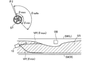
- FIGS. 2 and 3 are explanatory views showing an outline of the operation intervention control executed by the driving support ECU 100.
- FIG. FIGS. 2 and 3 show the steering angle of the steering ST included in the steering device 272 (counterclockwise is the positive direction) and the traveling environment of the vehicle 10 in association with each other. In this traveling environment, the vehicle 10 is traveling from the left side to the right side of the lane defined by the right side wall SW (R) and the left side wall SW (L), and there is an obstacle OB in front of the vehicle 10. is doing.
- 2 and 3 show a safety allowable region SR that is a region in which the behavior of the vehicle 10 should fall in order to ensure the safety of the vehicle 10.
- the driving assistance ECU 100 is permitted at the current time t because the predicted behavior of the vehicle 10 (trajectory in the present embodiment) falls within the safety tolerance region SR over the predicted section (temporal section in the present embodiment).
- An allowable control input range ⁇ safe (specifically, an allowable minimum value ⁇ min and an allowable maximum value ⁇ max of the steering angle ⁇ ), which is a range of operations (the steering angle ⁇ in the present embodiment), is calculated. 2 and 3, the trajectory VP ( ⁇ max ) of the vehicle 10 predicted when the steering angle at the current time t is the allowable maximum value ⁇ max and the steering angle at the current time t are allowable.
- a track VP ( ⁇ min ) of the vehicle 10 predicted when the minimum value ⁇ min is assumed is shown.
- the driving assistance ECU 100 does not perform the operation intervention when the steering angle ⁇ at the current time t is ⁇ 1 which is a value within the allowable control input range ⁇ safe , as in the example of FIG. 2, and the example of FIG. 3.
- the operation intervention is executed when the steering angle ⁇ at the current time t is ⁇ 2, which is a value outside the allowable control input range ⁇ safe .
- the operation intervention control executed by the driving assistance ECU 100 is an “emergency” operation intervention control in which an operation intervention is performed based only on a physical limit using a risk index such as a collision time margin (TTC). In other words, it can be said to be a “normal use” operation intervention control that operates at a stage where an urgent situation has not yet been reached (acts so as to avoid an urgent situation).
- TTC collision time margin
- driving behavior characteristic information DI indicating the driving behavior characteristics of each driver and vehicle characteristic information VI indicating the motion characteristics of the vehicle 10 are referred to.
- reference driving behavior information MI indicating a driving behavior characteristic of an exemplary driver is referred to for setting the safety tolerance region SR. This point will also be described in detail later.
- the driving assistance ECU 100 executes the above-described operation intervention control, as shown in FIG.
- An information storage unit 140 a driving behavior characteristic information management unit 150, an allowable control input range calculation unit 160, an operation intervention determination unit 170, and an operation intervention execution unit 180 are provided.
- the operation intervention execution unit 180 includes an intervention support input determination unit 182.
- the normative driving behavior information storage unit 110 of the driving assistance ECU 100 stores normative driving behavior information MI indicating the driving behavior characteristics of an exemplary driver.
- the safety tolerance region setting unit 120 sets the safety tolerance region SR with reference to the normative driving behavior information MI.
- the vehicle characteristic information storage unit 130 stores vehicle characteristic information VI indicating the movement characteristics of the vehicle 10.
- the driving behavior characteristic information management unit 150 generates and manages driving behavior characteristic information DI indicating the driving behavior characteristics of each driver.
- the driving behavior characteristic information storage unit 140 stores driving behavior characteristic information DI.
- the allowable control input range calculation unit 160 calculates the allowable control input range ⁇ safe .
- the operation intervention determination unit 170 determines whether or not to execute an operation intervention.
- the operation intervention execution unit 180 executes the operation intervention when it is determined to execute the operation intervention.
- the intervention support input determining unit 182 determines an intervention support input that is the degree of intervention when performing the operation intervention.
- the operation intervention control by the driving assistance ECU 100 will be described in more detail.
- the driving behavior characteristic information DI (FIG. 1) stored in the driving behavior characteristic information storage unit 140 is information indicating the driving behavior characteristics of each driver.
- the driving behavior characteristic is a behavior characteristic when each driver drives the vehicle 10, and includes, for example, a characteristic such as what kind of trajectory tends to follow at a certain speed in a certain traveling environment.
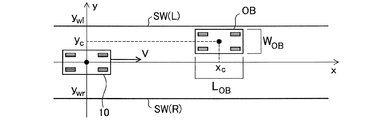
- FIG. 4 is an explanatory diagram illustrating an example of a traveling environment of the vehicle 10.
- the vehicle 10 the center of gravity
- the right side wall SW (R) is present on the right side when viewed from the vehicle 10
- the left side wall SW (L) is present on the left side
- the lane is defined by the two side walls SW.
- a parked vehicle having a length L OB in the x-axis direction and a width W OB in the y-axis direction exists as an obstacle OB at the coordinates (x c , y c ).
- y wr ⁇ 3.5 (m)
- y wl 3.5 (m)
- x c 70 (m)
- y c 1.57 (m)
- L OB 4.80 (m)
- W OB 1.94 (m).
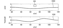
- 5 and 6 are explanatory diagrams showing an example of driving behavior characteristics of each driver.
- 5 shows a trajectory curve D (A) representing the travel trajectory of the vehicle 10 when the vehicle 10 travels by driving by the driver A in the travel environment shown in FIG.
- a yaw curve Y (A) representing a transition of the yaw of the vehicle 10 at that time is shown.
- FIG. 6 shows a trajectory curve D (B) and a yaw curve Y (B) when the vehicle 10 travels by driving by a driver B different from the driver A in the driving environment shown in FIG. Has been.
- the horizontal axis is the coordinate in the x-axis direction
- the vertical axis is the coordinate in the y-axis direction in the upper diagram
- the yaw angle (rad) of the vehicle 10 in the lower diagram As shown in FIGS. 5 and 6, even when traveling in the same traveling environment, the track curve D and the yaw curve Y may differ from one another depending on the driver. For example, the driver B who takes the driving action shown in FIG. 6 has an earlier start timing of the operation for avoiding the obstacle OB and the change in yaw is smaller than the driver A who takes the driving action shown in FIG. Therefore, it can be said that the vehicle has a driving behavior characteristic that more gently avoids the obstacle OB.
- the obstacle avoidance behavior of each driver is considered to be a manifestation of a sense of risk for the obstacle. Therefore, it is considered that the difference in the obstacle avoidance behavior of each driver, that is, the difference in the driving behavior characteristics is due to the difference in the risk feeling of each driver with respect to the obstacle. Therefore, in this embodiment, as an example of modeling of driving behavior characteristics, each driver's sense of risk is modeled and expressed as a parameter-represented potential function. Specifically, it is as follows.
- the attractive potential function U g from the goal on the straight path the repulsive potential function U w from the left and right boundaries (side walls and white lines) that define the lane, and the repulsive potential function U c from the obstacle OB are respectively.
- the following expressions (1) to (3) can be expressed.
- the attractive potential function U g from the goal is expressed as a linear potential function toward the front assuming that the goal is at infinity in the traveling direction.
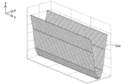
- the repulsive potential function U w from the left and right boundaries is expressed using a one-dimensional Gaussian function, assuming that the boundary length is infinite.
- FIG. 7 shows an example of the repulsive potential function U w from the left and right boundaries in the traveling environment of FIG.
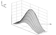
- the repulsive potential function U c from the obstacle OB is expressed using a two-dimensional Gaussian function.
- FIG. 8 shows an example of the repulsive potential function U c from the obstacle OB in the traveling environment of FIG. 7 and 8, the z-axis corresponds to the magnitude of the potential function.
- the magnitude of the attractive force, the magnitude of the repulsive force, the influence range, and the like can be adjusted. For example, when the size of the obstacle OB is different, It can be applied to various situations, such as when there is a difference in risk. In an actual driving environment, a plurality of these factors are combined at the same time. By using the superposition of these three potential functions, the driving behavior of the driver can be expressed.
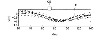
- FIG. 9 shows an example of the distribution of the coordinates P of the vehicle 10 at each time when the vehicle 10 is driven a plurality of times by driving by a driver in the driving environment shown in FIG.
- the parameter estimation problem of the potential function is formulated by the following optimization problem. ⁇ Parameter estimation problem>
- D (x i l , y i l ) is the steepest descent vector of the potential function U at the coordinates (x i l , y i l ).
- the evaluation function J in this optimization problem is the sum of the squares of the differences between the measured velocity vector v and the gradient vector d calculated from the potential field representing the sense of risk.
- the route generated by the potential field obtained as a result of the above optimization is expected to be similar to the driver's avoidance route, and the estimated parameters such as w ci, ⁇ cxi, ⁇ cyi are It is expected to express quantitatively the driver's sense of risk for obstacles in the driving environment.
- the estimated parameters are considered to be specific to the target intention or obstacle, and the same parameters can be used for similar obstacles even in different driving environments.
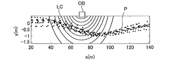
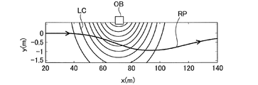
- FIG. 10 shows an example of a contour line LC of the potential field of the identified obstacle.
- the shape of the contour line LC may vary depending on the driver. Note that the evaluation function in the optimization problem for identifying the parameter of the potential function is not limited to the above-described one, and other functions can be taken.
- the driving behavior characteristic information management unit 150 (FIG. 1) of the vehicle 10 accumulates travel data of the vehicle 10 and estimates each parameter value of the potential function based on the accumulated travel data. Further, the driving behavior characteristic information DI for specifying each parameter value is generated and stored in the driving behavior characteristic information storage unit 140.
- the driving behavior characteristic information management unit 150 identifies a driver based on designation via a user interface (not shown) and accumulates driving data for each driver. Further, at a stage where sufficient driving data is not accumulated, for example, driving behavior characteristic information DI representing driving behavior characteristics of an average driver is stored in the driving behavior characteristic information storage unit 140, and sufficient traveling data is accumulated. At this stage, the driving behavior characteristic information DI is updated. Thereafter, the driving behavior characteristic information DI may be updated regularly or irregularly.
- the travel data corresponds to behavior information in the claims.
- the reference trajectory RP is a trajectory of the vehicle 10 in which the risk potential is as low as possible.
- the reference track RP needs to be a track on which the vehicle 10 can actually travel. That is, the vehicle 10 is subjected to nonholonomic restraint, and there is a limit to the steerable steering angle. Therefore, when generating the reference track RP, the vehicle characteristic information VI (FIG. 1) indicating the movement characteristic of the vehicle 10 stored in the vehicle characteristic information storage unit 130 is referred to.
- the vehicle characteristic information VI includes a vehicle movement characteristic model obtained by modeling the movement characteristic of the vehicle 10.
- a vehicle motion characteristic model there are a known two-wheel model represented by the following equations (8) to (10) and a known tire model represented by the following equations (11) to (12). used.
- This optimization problem is an optimization problem for searching for a front wheel steering angle and a state that minimizes a risk potential in a solution space that can be realized by a vehicle motion characteristic model.
- a reference trajectory RP is generated by the following procedure. By repeating this procedure, the path (x k , y k ) (k ⁇ ⁇ 1,2,3, ..., K ⁇ ) matched to the potential field is referenced under the constraint of the motion characteristic model of the vehicle 10 It is generated as a trajectory RP.
- FIG. 11 shows an example of the generated reference trajectory RP. • Step 1: Set the initial value.
- Step 2 Solve the above optimization problem, and calculate ⁇ k + 1 that advances the vehicle 10 in the direction of the lowest potential while satisfying the constraints of the vehicle motion characteristic model in the potential field adapted to each driver. .
- Step 3 Based on the obtained ⁇ k + 1 , the states x k + 1 , y k + 1 , ⁇ k + 1 at the next step are calculated based on the motion characteristic model of the vehicle 10.
- the safety tolerance region SR is set with reference to the normative driving behavior information MI (FIG. 1) stored in the normative driving behavior information storage unit 110.
- the normative driving behavior information MI is information indicating the driving behavior characteristics of an exemplary driver (for example, an instructor at a driving school), and in this embodiment, information indicating each parameter value of the potential function for the exemplary driver. (That is, exemplary driving behavior characteristic information DI of a driver).
- the normative driving behavior information MI corresponds to the specific driving behavior information in the claims.
- FIG. 12 is an explanatory diagram illustrating an example of a method for setting the safety tolerance region SR.
- FIG. 12 shows a reference trajectory RP generated using each parameter value of the potential function for an exemplary driver.
- This reference track RP can be said to be an exemplary track of the vehicle 10 in the specific traveling environment in which the reference track RP is generated.
- an area including the reference trajectory RP and having a width calculated in consideration of dispersion is set as the safety allowable area SR.
- the safety tolerance region SR corresponds to a predetermined region in the claims.
- the allowable control input range ⁇ safe is such that the trajectory of the vehicle 10 predicted with reference to the driving behavior characteristic information DI and the vehicle characteristic information VI falls within the safety allowable region SR over the prediction interval.
- the range of the steering angle allowed at the current time t (the minimum allowable value ⁇ min and the maximum allowable value ⁇ max of the steering angle ⁇ ).
- the allowable control input range calculation unit 160 sets the allowable control input range ⁇ safe by solving the following allowable control input range calculation problem from the viewpoint of satisfaction of constraints. ⁇ Allowable control input range calculation problem>
- Operation intervention judgment and operation intervention execution Next, operation intervention determination by the operation intervention determination unit 170 (FIG. 1) and operation intervention execution by the operation intervention execution unit 180 will be described.
- Operating the intervention determination unit 170 determines whether ⁇ steering angle at the current time t is in the allowable control input range ⁇ in safe, the steering angle ⁇ is in the allowable control input range ⁇ within safe at the present time t In this case, it is determined not to perform the operation intervention, and when the steering angle ⁇ at the current time t is outside the allowable control input range ⁇ safe , it is determined to perform the operation intervention.
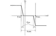
- FIG. 13 is an explanatory diagram illustrating an example of a method for determining the intervention support input Ua.
- the intervention support input Ua is preliminarily set in both cases where the steering angle ⁇ at the current time t is larger than the allowable maximum value ⁇ max and when the steering angle ⁇ at the current time t is smaller than the allowable minimum value ⁇ min. It is determined to be a fixed value.
- This value is variably set according to the driving ability of each driver.
- the steering angle ⁇ in order to smooth the operation feeling and further reduce the driver's uncomfortable feeling, the steering angle ⁇ also in the transition area ⁇ tra which is the area near the boundary on both sides in the allowable control input range ⁇ safe .
- the operation intervention is executed with the intervention support input Ua according to the above. That is, in the example of FIG. 13, the operation intervention is not performed when the steering angle ⁇ at the current time t is in a region other than the transition region ⁇ tra within the allowable control input range ⁇ safe .
- the operation intervention execution unit 180 performs an operation intervention on steering with the intervention support input Ua determined by the intervention support input determination unit 182 via the steering ECU 270.
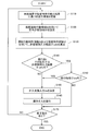
- FIG. 14 is a flowchart showing the flow of the operation intervention control process by the driving assistance ECU 100 of the present embodiment.
- the driving assistance ECU 100 indicates a detection result of a lane boundary or an obstacle, a driving operation, a vehicle speed, a yaw rate, and the like from the driving operation detection unit 210, the vehicle speed sensor 220, the yaw rate sensor 230, the radar unit 250, the camera unit 260, and the like.
- Information is acquired and the traveling environment of the vehicle 10 is grasped (S110).
- the safety permissible area setting unit 120 sets the safety permissible area SR (see FIG. 12) according to the grasped driving environment using the normative driving behavior information MI (step S120).
- the allowable control input range calculation unit 160 calculates the allowable control input range ⁇ safe (see FIGS. 2 and 3) using the driving behavior characteristic information DI and the vehicle characteristic information VI (S130).
- the operation intervention determination unit 170 determines in real time whether or not the operation (steering angle ⁇ ) at the current time t is within the allowable control input range ⁇ safe (S140). When it is determined that the steering angle ⁇ at the current time t is outside the allowable control input range ⁇ safe (S140: NO), the intervention support input determination unit 182 determines the intervention support input Ua (S150), The operation intervention execution unit 180 executes the operation intervention with the determined intervention support input Ua (S160).
- the operation intervention determination unit 170 shifts the steering angle ⁇ at the current time t. It is determined whether or not it is within the region ⁇ tra (see FIG. 13) (S142). When it is determined that the steering angle ⁇ at the current time t is within the transition region ⁇ tra (S142: YES), the intervention support input determination unit 182 determines the intervention support input Ua (S150), and the operation intervention is performed. The unit 180 executes the operation intervention with the determined intervention support input Ua (S160). If it is determined that the rudder angle ⁇ at the current time t is within the allowable control input range ⁇ safe (S140: YES) and outside the transition region ⁇ tra (S142: NO), S150 and S160 Processing is skipped.
- the driving support ECU 100 repeatedly executes the above-described processes from S110 to S160 while an instruction to end the process is not received (S170: NO). When an instruction to end the process is received (S170: YES), the driving support ECU 100 ends the operation intervention control process.
- the safety allowable region setting unit 120 sets the safety allowable region SR that is a region related to the track of the vehicle 10, and the allowable control input range calculation unit 160 Of the steering angle ⁇ permitted at the current time t so that the trajectory of the vehicle 10 predicted using the driving behavior characteristic information DI indicating the driving behavior characteristics of the driver of the driver falls within the safety tolerance region SR over the predetermined prediction section.
- the allowable control input range ⁇ safe that is the range is calculated, and the operation intervention determination unit 170 determines whether or not the steering angle ⁇ at the current time t is within the allowable control input range ⁇ safe , and at the current time t.
- the operation intervention execution unit 180 executes an operation intervention regarding steering.
- the driving support ECU 100 uses the driving behavior characteristic information DI for the trajectory prediction of the vehicle 10 for calculating the allowable control input range ⁇ safe while ensuring the safety by the operation intervention. Therefore, the driver's uncomfortable feeling due to the operation intervention can be further reduced as compared with the conventional configuration in which it is determined whether or not the operation intervention is executed by a uniform determination method.
- the safety allowable region SR is set using the normative driving behavior information MI which is the exemplary driving behavior characteristic information DI of the driver, the driver is exemplified by the operation intervention. Safe driving behavior can be ensured, and safety can be more reliably achieved.
- the driving behavior characteristic information management unit 150 accumulates and accumulates driving data (behavior information) indicating the behavior of the vehicle 10 while the vehicle 10 is traveling in association with the driver. Because driving behavior characteristic information DI is generated using the travel data, it is possible to create driving behavior characteristic information DI that accurately reflects the driving behavior characteristics of the driver, and more effective driver discomfort due to operation intervention. Can be reduced.
- the vehicle characteristic information VI indicating the movement characteristic of the vehicle 10 is used for the trajectory prediction of the vehicle 10 for calculating the allowable control input range ⁇ safe , and thus the movement characteristic of the vehicle 10 is calculated. Therefore, it is possible to predict an appropriate trajectory in consideration of the above, and to ensure both safety and reduction of discomfort at a high level.
- the intervention support input determining unit 182 can variably determine the intervention support input Ua, so that the operation is performed with an appropriate intervention support input Ua according to the driving ability of the driver. Intervention can be performed.
- the trajectory of the vehicle 10 predicted when the allowable control input range calculation unit 160 calculates the allowable control input range ⁇ safe is a trajectory when no operation intervention is performed. Compared with the trajectory prediction when the operation intervention is performed, the trajectory prediction can be performed with high accuracy, and as a result, the determination of whether or not the operation intervention can be performed can be performed with high accuracy.
- the operation intervention control for the steering of the vehicle 10 has been described.
- the present invention is also applied to the operation intervention control for the braking of the vehicle 10, for example, when the vehicle 10 is temporarily stopped at an intersection with poor visibility. Is possible.
- the present invention is applied to the operation intervention control for braking, for example, it is as follows.
- FIG. 15 is an explanatory diagram illustrating an example of a method of setting the safety tolerance region SR in the modification.
- the vertical axis represents the speed of the vehicle 10 and the horizontal axis represents the distance from the intersection.
- a stop line SL exists at a position 5 (m) before the intersection.
- FIG. 15 shows a reference track RP generated using exemplary driver travel data, and a safety tolerance region SR for a vehicle speed set with a certain width in the reference track RP.
- the operation intervention control for acceleration may be executed. For example, when it is determined that the vehicle speed falls below the safety tolerance region SR in the predicted section, an operation intervention that increases the depression angle of the accelerator pedal may be performed.
- the present invention not only the operation intervention regarding steering but also the operation intervention regarding braking and acceleration, it is possible to further reduce the driver's uncomfortable feeling while ensuring safety by the operation intervention. it can.
- the configuration of the vehicle 10 in the above embodiment is merely an example, and the vehicle 10 may not include some of the components described above, or the vehicle 10 may include components not described above.
- the model representing the driving behavior characteristic of the driver described in the above embodiment is merely an example, and other models such as a hybrid dynamic system model may be employed.
- the model representing the vehicle motion characteristics described in the above embodiment is merely an example, and other models such as a steady circle turning model and a constant velocity model may be employed.
- the intervention support input Ua is determined to be a predetermined constant value outside the allowable control input range ⁇ safe (see FIG. 13), but the intervention support input Ua is steered at the current time. It may be changed according to the angle ⁇ .
- the operation intervention an acceptable control input range theta within safe may be not executed at all.
- the safety tolerance region SR is set using the normative driving behavior information MI that is the driving behavior characteristic information DI of the exemplary driver.
- the safe allowable area SR may be set using the driving behavior characteristic information DI. Further, it is not always necessary to use the driving behavior characteristic information DI when setting the safety tolerance region SR. If the behavior of the vehicle 10 is set to be within the range in order to ensure the safety of the vehicle 10, the safety tolerance region is set.
- An arbitrary method can be adopted as the SR setting method.
- the prediction interval is a temporal interval, but the prediction interval may be a distance interval.
- the driving assistance ECU 100 executes the operation intervention control in the normal range that operates in a situation where an emergency has not yet been reached.
- the driving assistance ECU 100 adds, for example, a collision time margin (TTC). It is also possible to execute an emergency operation intervention control in which an operation intervention is performed based only on physical limits using a risk index such as).
- Vehicle 100 Driving support ECU 110: Standard driving behavior information storage unit 120: Safety tolerance region setting unit 130: Vehicle characteristic information storage unit 140: Driving behavior characteristic information storage unit 150: Driving behavior characteristic information management unit 160: Permissible control Input range calculation unit 170: operation intervention determination unit 180: operation intervention execution unit 182: intervention support input determination unit 210: driving operation detection unit 220: vehicle speed sensor 230: yaw rate sensor 240: GPS 250: radar unit 260: camera unit 270: Steering ECU 272: Steering device 280: Brake ECU 282: Brake device DI: Driving behavior characteristic information MI: Standard driving behavior information VI: Vehicle characteristic information
Abstract
車両の所定の操作に対する介入制御において、安全性確保を達成しつつ、運転者の違和感をより低減する。 車両の所定の操作に対する介入を行う運転支援装置は、車両の挙動に関する領域である所定領域を設定する領域設定部と、車両の運転者の運転行動特性を示す運転行動特性情報を取得し、取得された運転行動特性情報を用いて予測される車両の挙動が所定の予測区間にわたって所定領域内に収まるために現時刻で許容される操作の範囲である許容制御入力範囲を算出する許容制御入力範囲算出部と、現時刻の操作が許容制御入力範囲内にあるか否かを判定する判定部と、現時刻の操作が許容制御入力範囲の外にあると判定された場合に、介入を実行する操作介入実行部と、を備える。
Description
本明細書に開示される技術は、運転支援装置に関する。
車両が障害物等と衝突することを防止したり車両を所定の位置で停止させたりして車両の安全性を確保するために、車両の操舵や制動について、運転者による操作に介入を行う運転支援装置が知られている。運転支援装置には、安全性確保を達成しつつ、操作介入による運転者の違和感をできるだけ低減することが求められる。従来、操作介入が実行された場合の車両が取り得る軌道を複数算出し、障害物の存在する領域と重複しない軌道の数が所定数を超える場合には、違和感低減を優先して操作介入を実行せず、障害物の存在する領域と重複しない軌道の数が所定数以下である場合に、安全性確保を優先して操作介入を実行することにより、安全性確保と違和感低減との両立を図る技術が知られている(例えば特許文献1参照)。
車両の運転者としては、若年者や高齢者、初心者や熟練者など様々な運転者がおり、各運転者の運転行動特性は互いに異なり得る。上記従来の技術では、このような運転行動特性の違いを考慮することなく一律の判定手法によって操作介入を実行するか否かを判定しているため、運転者によっては、違和感を強く覚えたり、反対に、安全性確保が達成できなかったりする恐れがある。このように、従来の運転支援装置は、安全性確保と違和感低減との両立の点で改善の余地がある。
本明細書では、上述した課題の少なくとも一部を解決することが可能な技術を開示する。
本明細書に開示される技術は、例えば、以下の形態として実現することが可能である。
(1)本明細書に開示される運転支援装置は、車両の所定の操作に対する介入を行う運転支援装置であって、前記車両の挙動に関する領域である所定領域を設定する領域設定部と、前記車両の運転者の運転行動特性を示す運転行動特性情報を取得し、取得された前記運転行動特性情報を用いて予測される前記車両の挙動が所定の予測区間にわたって前記所定領域内に収まるために現時刻で許容される前記操作の範囲である許容制御入力範囲を算出する許容制御入力範囲算出部と、現時刻の前記操作が前記許容制御入力範囲内にあるか否かを判定する判定部と、現時刻の前記操作が前記許容制御入力範囲の外にあると判定された場合に、前記介入を実行する操作介入実行部と、を備える。本運転支援装置によれば、操作介入による安全性の確保を達成しつつ、許容制御入力範囲算出のための車両の挙動予測に運転行動特性情報を用いることによって、一律の判定手法によって操作介入を実行するか否かを判定する従来の構成と比較して、操作介入による運転者の違和感をより低減することができる。
(2)上記運転支援装置において、前記領域設定部は、特定の運転者の前記運転行動特性情報である特定運転行動情報を取得し、取得された前記特定運転行動情報を用いて前記所定領域を設定する構成としてもよい。本運転支援装置によれば、操作介入によって運転者を特定の運転行動(例えば模範的とされる運転行動)に誘導することができ、安全性の確保をより確実に達成することができる。
(3)上記運転支援装置において、さらに、前記車両の走行中に前記車両の挙動を示す挙動情報を前記車両の運転者に対応付けて蓄積し、蓄積された前記挙動情報を用いて前記運転行動特性情報を生成する運転行動特性情報管理部を備える構成としてもよい。本運転支援装置によれば、運転者の運転行動特性を精度良く反映した運転行動特性情報を作成することができ、操作介入による運転者の違和感をより効果的に低減することができる。
(4)上記運転支援装置において、前記許容制御入力範囲算出部は、前記車両の運動特性を示す車両特性情報を取得し、前記運転行動特性情報と前記車両特性情報とを用いて前記車両の挙動を予測する構成としてもよい。本運転支援装置によれば、車両の運動特性を考慮した適切な挙動を予測することができ、安全性の確保と違和感の低減とを高次元で両立させることができる。
(5)上記運転支援装置において、さらに、前記介入の程度を可変に決定する介入支援入力決定部を備える構成としてもよい。本運転支援装置によれば、運転者の運転能力等に応じた適切な介入の程度で操作介入を行うことができる。
(6)上記運転支援装置において、前記操作は、操舵操作であり、前記車両の挙動は、前記車両のとる軌道を含む構成としてもよい。本運転支援装置によれば、操舵操作についての操作介入による運転者の違和感をより低減することができる。
(7)上記運転支援装置において、前記操作は、制動操作と加速操作との少なくとも一方であり、前記車両の挙動は、前記車両の速度を含む構成としてもよい。本運転支援装置によれば、制動と加速との少なくとも一方についての操作介入による運転者の違和感をより低減することができる。
(8)上記運転支援装置において、前記許容制御入力範囲算出部は、前記介入が実行されない場合の前記車両の挙動を予測する構成としてもよい。本運転支援装置によれば、操作介入が実行される場合の挙動予測と比較して、精度良く挙動予測を行うことができ、その結果、操作介入実行可否の判定を精度良く行うことができる。
なお、本明細書に開示される技術は、種々の形態で実現することが可能であり、例えば、運転支援装置、運転支援装置を備える車両、運転支援方法、車両の制御方法、それらの方法を実現するコンピュータープログラム、そのコンピュータープログラムを記録した一時的でない記録媒体等の形態で実現することができる。
A.実施形態:
A-1.装置の構成:
図1は、本実施形態における車両10の概略構成を示す説明図である。車両10は、運転操作検出部210と、車速センサ220と、ヨーレートセンサ230と、GPS240と、レーダユニット250と、カメラユニット260と、運転支援電子制御ユニット(以下、「電子制御ユニット」を「ECU」という)100と、ステアリングECU270と、ステアリング装置272と、ブレーキECU280と、ブレーキ装置282とを備えている。車両10に含まれる各ECUは、CPUや記憶部を含むコンピュータにより構成されており、例えばCAN(Control Area Network)等の車両内ネットワークを介して互いに接続されている。
ステアリング装置272は、車両10の進行方向を変える操舵装置である。ステアリングECU270は、ステアリング装置272の動作を制御する。ブレーキ装置282は、車両10に制動力を発生させる装置である。ブレーキECU280は、ブレーキ装置282の動作を制御する。
運転操作検出部210は、運転者による車両10の運転操作を検出するセンサである。運転操作検出部210は、例えば、ステアリング装置272に含まれるステアリングの舵角を検出する舵角センサと、ブレーキ装置282に含まれるブレーキペダルの踏み込み角を検出するブレーキペダルセンサとを含む。運転操作検出部210は、検出した運転操作(舵角やブレーキペダルの踏み込み角)を示す情報を運転支援ECU100に出力する。
車速センサ220は、車両10の速度を検出するセンサであり、検出した車両10の速度を示す情報を運転支援ECU100に出力する。ヨーレートセンサ230は、車両10に生ずるヨーレートを検出するセンサであり、検出した車両10のヨーレートを示す情報を運転支援ECU100に出力する。GPS240は、車両10の位置を検出するセンサであり、検出した車両10の位置を示す情報を運転支援ECU100に出力する。
レーダユニット250は、例えばミリ波を用いるレーダを備えており、車両10の周辺の障害物を検出したり、車両10が走行すべき車線を規定する物体(例えば側壁等)を検出することによって車線を検出したりする。なお、障害物は、例えば他の走行車両や、駐車車両、歩行者等である。また、車線を規定する物体も障害物となり得る。レーダユニット250は、検出した障害物や車線の位置を示す情報を運転支援ECU100に出力する。
カメラユニット260は、カメラを備えており、カメラにより撮影された画像を解析することにより、車両10の周辺の障害物を検出したり、車両10が走行すべき車線を規定する物体(例えば側壁や白線等)を検出することによって車線を検出したりする。カメラユニット260は、検出した障害物や車線の位置を示す情報を運転支援ECU100に出力する。
運転支援ECU100は、車両10が障害物と衝突することを防止して車両10の安全性を確保するために、車両10の操舵についての操作介入制御を行う装置である。車両10の操舵についての操作介入制御とは、ステアリングECU270に、運転者による操舵操作に対する介入、すなわち、運転者の操作によらない強制的な操舵動作を実行させる制御である。
運転支援ECU100によって実行される操作介入制御の詳細については後述するが、概要は以下の通りである。図2および図3は、運転支援ECU100によって実行される操作介入制御の概要を示す説明図である。図2および図3には、ステアリング装置272に含まれるステアリングSTの舵角(反時計回りが正方向)と車両10の走行環境とが対応付けて示されている。この走行環境では、車両10が右側壁SW(R)および左側壁SW(L)で規定された車線を図の左側から右側に向けて走行しており、車両10の前方に障害物OBが存在している。また、図2および図3には、車両10の安全が確保されるために車両10の挙動が収まるべき領域である安全許容領域SRが示されている。
運転支援ECU100は、予測される車両10の挙動(本実施形態では軌道)が予測区間(本実施形態では時間的な区間)にわたって安全許容領域SR内に収まるために、現時刻tで許容される操作(本実施形態では舵角θ)の範囲である許容制御入力範囲θsafe(具体的には舵角θの許容最小値θminおよび許容最大値θmax)を算出する。図2および図3には、現時刻tでの舵角が許容最大値θmaxであるとした場合に予測される車両10の軌道VP(θmax)と、現時刻tでの舵角が許容最小値θminであるとした場合に予測される車両10の軌道VP(θmin)とが示されている。運転支援ECU100は、図2の例のように、現時刻tでの舵角θが許容制御入力範囲θsafe内の値であるθ1である場合には操作介入を実行せず、図3の例のように、現時刻tでの舵角θが許容制御入力範囲θsafeの外の値であるθ2である場合に操作介入を実行する。このように、運転支援ECU100によって実行される操作介入制御は、例えば衝突時間余裕(TTC)等の危険度指標を用いて物理的限界のみに基づき操作介入を行う「緊急時の」操作介入制御ではなく、いまだ緊急的な状況に至っていない段階で動作する(緊急的な状況を回避するように動作する)いわば「常用域の」操作介入制御であると言える。
なお、車両10の軌道予測の際には、各運転者の運転行動特性を示す運転行動特性情報DIと、車両10の運動特性を示す車両特性情報VIとが参照される。また、安全許容領域SRの設定には、模範的な運転者の運転行動特性を示す規範運転行動情報MIが参照される。この点についても後に詳述する。
運転支援ECU100は、上述した操作介入制御を実行するため、図1に示すように、規範運転行動情報記憶部110と、安全許容領域設定部120と、車両特性情報記憶部130と、運転行動特性情報記憶部140と、運転行動特性情報管理部150と、許容制御入力範囲算出部160と、操作介入判定部170と、操作介入実行部180とを備えている。操作介入実行部180は、介入支援入力決定部182を含んでいる。
運転支援ECU100の規範運転行動情報記憶部110は、模範的な運転者の運転行動特性を示す規範運転行動情報MIを記憶する。安全許容領域設定部120は、規範運転行動情報MIを参照して、安全許容領域SRを設定する。車両特性情報記憶部130は、車両10の運動特性を示す車両特性情報VIを記憶する。運転行動特性情報管理部150は、各運転者の運転行動特性を示す運転行動特性情報DIの生成・管理を行う。運転行動特性情報記憶部140は、運転行動特性情報DIを記憶する。許容制御入力範囲算出部160は、許容制御入力範囲θsafeを算出する。操作介入判定部170は、操作介入を実行するか否かを判定する。操作介入実行部180は、操作介入を実行すると判定された場合に、操作介入を実行する。介入支援入力決定部182は、操作介入を実行する際の介入の程度である介入支援入力を決定する。以下、運転支援ECU100による操作介入制御についてより詳細に説明する。
A-2.運転行動特性情報DIについて:
運転行動特性情報記憶部140に記憶される運転行動特性情報DI(図1)は、各運転者の運転行動特性を示す情報である。運転行動特性とは、各運転者が車両10を運転する際の行動特性であり、例えば、ある走行環境においてどの程度の速度でどのような軌道をたどる傾向にあるか、といった特性が含まれる。
運転行動特性情報記憶部140に記憶される運転行動特性情報DI(図1)は、各運転者の運転行動特性を示す情報である。運転行動特性とは、各運転者が車両10を運転する際の行動特性であり、例えば、ある走行環境においてどの程度の速度でどのような軌道をたどる傾向にあるか、といった特性が含まれる。
図4は、車両10の走行環境の一例を示す説明図である。図4に示す走行環境では、x軸方向に延びる直線状の一方通行の道路における座標(0,0)に車両10(の重心)が位置し、x軸正方向に向かって速度Vで直進している。車両10から見て右側には右側壁SW(R)が存在し、左側には左側壁SW(L)が存在し、2つの側壁SWによって車線が規定されている。右側壁SW(R)はy=ywrで表され、左側壁SW(L)はy=ywlで表される。また、座標(xc,yc)に、障害物OBとして、x軸方向の長さLOBでy軸方向の幅WOBの駐車車両が存在する。例えばywr=-3.5(m)であり、ywl=3.5(m)であり、xc=70(m)であり、yc=1.57(m)であり、LOB=4.80(m)であり、WOB=1.94(m)である。
図5および図6は、各運転者の運転行動特性の一例を示す説明図である。図5の上段には、図4に示した走行環境において運転者Aによる運転で車両10が走行した際の車両10の走行軌道を表す軌道曲線D(A)が示されており、図5の下段には、その際の車両10のヨーの推移を表すヨー曲線Y(A)が示されている。同様に、図6には、図4に示した走行環境において運転者Aとは異なる運転者Bによる運転で車両10が走行した際の軌道曲線D(B)およびヨー曲線Y(B)が示されている。図5および図6のそれぞれにおいて、横軸はx軸方向の座標であり、縦軸は、上段の図ではy軸方向の座標、下段の図では車両10のヨー角(rad)である。図5および図6に示すように、同一の走行環境を走行する場合であっても、運転者によって、軌道曲線Dやヨー曲線Yは互いに異なり得る。例えば、図6に示す運転行動をとる運転者Bは、図5に示す運転行動をとる運転者Aと比べて、障害物OBを回避する動作の開始タイミングが早く、またヨーの変化も小さいことから、より緩やかに障害物OBを回避する運転行動特性を有していると言える。
各運転者の障害物回避行動は、その障害物に対するリスク感が顕在化したものであると考えられる。そのため、各運転者の障害物回避行動の違い、すなわち、運転行動特性の違いの一因は、障害物に対する各運転者のリスク感の違いにあるものと考えられる。そこで、本実施形態では、運転行動特性のモデル化の一例として、各運転者のリスク感をモデル化し、パラメータ表現されたポテンシャル関数として表すものとした。具体的には、以下の通りである。
まず、直進路におけるゴールからの引力ポテンシャル関数Ugと、車線を規定する左右の境界(側壁や白線)からの斥力ポテンシャル関数Uwと、障害物OBからの斥力ポテンシャル関数Ucとは、それぞれ、以下の式(1)-(3)のように表現することができる。

上記式(1)に示すように、ゴールからの引力ポテンシャル関数Ugは、ゴールを進行方向の無限遠にあると仮定して、前方に向かう線形のポテンシャル関数として表現される。また、左右の境界からの斥力ポテンシャル関数Uwは、境界の長さが無限であるとして、一次元のガウス関数を用いて表現される。図7に、図4の走行環境における左右の境界からの斥力ポテンシャル関数Uwの一例を示す。また、障害物OBからの斥力ポテンシャル関数Ucは、二次元ガウス関数を用いて表現される。図8に、図4の走行環境における障害物OBからの斥力ポテンシャル関数Ucの一例を示す。図7および図8において、z軸はポテンシャル関数の大きさに対応する。
上述した3つのポテンシャル関数の各パラメータを変化させることにより、引力の大きさや斥力の大きさ、影響範囲等を調整することができ、例えば、障害物OBの大きさが異なる場合や、運転者のリスク感に違いがある場合等、多様な状況に適用することができる。実際の走行環境では、これらの要因が複数同時に組み合わさっているが、これら3つのポテンシャル関数の重ね合わせを用いることにより、運転者の運転行動を表現することができる。
上述したポテンシャル関数を各運転者に適合させるため、本実施形態では、各運転者の運転による車両10の走行の際に観測された走行データを用いて、ポテンシャル関数の各パラメータ値を推定するものとしている。具体的には、走行データとして、所定の走行環境において車両10を走行させたときの、各時刻での車両10の座標(xi
l, yi
l)と速度v(xi
l, yi
l)とを取得する。なお、l={1, 2,...,L}は試行番号であり、i={1, 2,...,n l }はデータのインデックスであり、n l はl回目の試行で得られたデータ数である。図9に、図4に示す走行環境においてある運転者の運転により車両10を複数回走行させた際の、各時刻での車両10の座標Pの分布の一例を示す。
次に、走行環境に含まれる主要な要素を列挙し、例えば下記の式(4)のようにそれらの重ね合わせとして走行環境を表現するポテンシャル関数U(x, y)を構築する。

ポテンシャル関数のパラメータの推定問題は、以下の最適化問題により定式化される。
<パラメータ推定問題>

<パラメータ推定問題>
本実施形態では、車両10がレーダユニット250やカメラユニット260を備えているため、車線の境界の座標や障害物の座標は既知である。また、d(xi
l, yi
l)は、座標(xi
l, yi
l)におけるポテンシャル関数Uの最急降下ベクトルである。この最適化問題における評価関数Jは、計測された速度ベクトルvとリスク感を表すポテンシャル場から計算された勾配ベクトルdとの差の二乗の総和である。従って、上記最適化の結果得られたポテンシャル場により生成される経路は、運転者の回避経路と似たものとなることが期待され、wci, σcxi, σcyi等の推定されたパラメータは、走行環境上の障害物に対するドライバのリスク感を定量的に表現するものと期待される。推定されたパラメータは、対象となる意図や障害物に固有のものと考えられ、異なる走行環境中であっても類似した障害物には同じパラメータを用いることが可能である。図10に、同定された障害物のポテンシャル場の等高線LCの一例を示す。運転者により、等高線LCの形状は異なり得る。なお、ポテンシャル関数のパラメータの同定のための最適化問題における評価関数は、上述したものに限られず、他の関数を取り得る。
本実施形態では、車両10の運転行動特性情報管理部150(図1)が、車両10の走行データを蓄積し、蓄積された走行データに基づき上記ポテンシャル関数の各パラメータ値を推定し、推定された各パラメータ値を特定する運転行動特性情報DIを生成して運転行動特性情報記憶部140に格納する。なお、運転行動特性情報管理部150は、図示しないユーザインタフェースを介した指定等に基づき運転者を識別し、運転者毎に走行データを蓄積する。また、十分な走行データが蓄積されていない段階では、例えば平均的な運転者の運転行動特性を表す運転行動特性情報DIが運転行動特性情報記憶部140に格納され、十分な走行データが蓄積された段階で、運転行動特性情報DIの更新が実行される。なお、その後、定期的にまたは不定期で、運転行動特性情報DIの更新が行われるとしてもよい。走行データは、特許請求の範囲における挙動情報に相当する。
A-3.安全許容領域SRの設定:
次に、安全許容領域設定部120(図1)による安全許容領域SRの設定について説明する。上記ポテンシャル関数の各パラメータ値が推定され、各パラメータ値を特定する運転行動特性情報DIが生成されると、運転行動特性情報DIを用いて参照軌道RPを生成することができる。参照軌道RPは、リスクポテンシャルができるだけ低い値をとる車両10の軌道である。ただし、参照軌道RPは、実際に車両10が走行可能な軌道である必要がある。すなわち、車両10は非ホロノミックな拘束を受け、また実現可能な舵角にも制限がある。そのため、参照軌道RPの生成の際には、車両特性情報記憶部130に記憶された車両10の運動特性を示す車両特性情報VI(図1)が参照される。
次に、安全許容領域設定部120(図1)による安全許容領域SRの設定について説明する。上記ポテンシャル関数の各パラメータ値が推定され、各パラメータ値を特定する運転行動特性情報DIが生成されると、運転行動特性情報DIを用いて参照軌道RPを生成することができる。参照軌道RPは、リスクポテンシャルができるだけ低い値をとる車両10の軌道である。ただし、参照軌道RPは、実際に車両10が走行可能な軌道である必要がある。すなわち、車両10は非ホロノミックな拘束を受け、また実現可能な舵角にも制限がある。そのため、参照軌道RPの生成の際には、車両特性情報記憶部130に記憶された車両10の運動特性を示す車両特性情報VI(図1)が参照される。
車両特性情報VIには、車両10の運動特性をモデル化した車両運動特性モデルが含まれる。本実施形態では、車両運動特性モデルとして、下記の式(8)-(10)で表される公知の二輪モデルや、下記の式(11)-(12)で表される公知のタイヤモデルが使用される。


参照軌道RPの生成手順には、タイヤ切れ角に関する物理的な制約と、上述の車両10の運動特性を時間に関して離散化したものを拘束条件とした以下の最適化問題が組み込まれている。
<参照軌道RPの生成に用いる最適化問題>

<参照軌道RPの生成に用いる最適化問題>
この最適化問題は、車両運動特性モデルにより実現可能な解空間の中で、リスクポテンシャルを最小にする前輪舵角と状態を探索する最適化問題となっている。この最適化問題を用い、以下の手順により参照軌道RPを生成する。この手順を繰り返すことにより、車両10の運動特性モデルの拘束下で、ポテンシャル場に合わせた経路(xk,yk)(k∈{1,2,3,...,K})が参照軌道RPとして生成される。図11に、生成された参照軌道RPの一例を示す。
・Step 1:初期値を設定する。(k=1, (xk,yk,θk)=(x0, ,y0, θ0)とする。)
・Step 2:上述の最適化問題を解き、各運転者に適合されたポテンシャル場において、車両運動特性モデルの制約を満たしつつ、ポテンシャルを最も下る方向に車両10を進めるδk+1を計算する。
・Step 3:求められたδk+1をもとに、車両10の運動特性モデルに基づき、次ステップでの状態xk+1,yk+1,θk+1を計算する。
・Step 4:k+1=K(Kは所望の生成ステップ数)となれば終了する。そうでなければk=k+1として、Step 2に戻る。
・Step 1:初期値を設定する。(k=1, (xk,yk,θk)=(x0, ,y0, θ0)とする。)
・Step 2:上述の最適化問題を解き、各運転者に適合されたポテンシャル場において、車両運動特性モデルの制約を満たしつつ、ポテンシャルを最も下る方向に車両10を進めるδk+1を計算する。
・Step 3:求められたδk+1をもとに、車両10の運動特性モデルに基づき、次ステップでの状態xk+1,yk+1,θk+1を計算する。
・Step 4:k+1=K(Kは所望の生成ステップ数)となれば終了する。そうでなければk=k+1として、Step 2に戻る。
上述したように、安全許容領域SRは、規範運転行動情報記憶部110に記憶された規範運転行動情報MI(図1)を参照して設定される。規範運転行動情報MIは、模範的な運転者(例えば教習所の教官)の運転行動特性を示す情報であり、本実施形態では、模範的な運転者についての上記ポテンシャル関数の各パラメータ値を示す情報(すなわち、模範的な運転者の運転行動特性情報DI)である。なお、規範運転行動情報MIは、特許請求の範囲における特定運転行動情報に相当する。
図12は、安全許容領域SRの設定方法の一例を示す説明図である。図12には、模範的な運転者についてのポテンシャル関数の各パラメータ値を用いて生成された参照軌道RPが示されている。この参照軌道RPは、参照軌道RPが生成された特定の走行環境において、車両10の模範的な軌道であると言える。本実施形態では、この参照軌道RPを含み、分散を考慮して算出された幅を持たせた領域が、安全許容領域SRとして設定される。なお、安全許容領域SRは、特許請求の範囲における所定領域に相当する。
A-4.許容制御入力範囲θsafeの算出:
次に、許容制御入力範囲算出部160(図1)による許容制御入力範囲θsafeの算出について説明する。上述したように、許容制御入力範囲θsafeは、運転行動特性情報DIと車両特性情報VIとを参照して予測される車両10の軌道が、予測区間にわたって安全許容領域SR内に収まるために、現時刻tで許容される舵角の範囲(舵角θの許容最小値θminおよび許容最大値θmax)である。許容制御入力範囲算出部160は、許容制御入力範囲θsafeを、以下の許容制御入力範囲算出問題を制約充足の観点から解くことにより設定する。
<許容制御入力範囲算出問題>

次に、許容制御入力範囲算出部160(図1)による許容制御入力範囲θsafeの算出について説明する。上述したように、許容制御入力範囲θsafeは、運転行動特性情報DIと車両特性情報VIとを参照して予測される車両10の軌道が、予測区間にわたって安全許容領域SR内に収まるために、現時刻tで許容される舵角の範囲(舵角θの許容最小値θminおよび許容最大値θmax)である。許容制御入力範囲算出部160は、許容制御入力範囲θsafeを、以下の許容制御入力範囲算出問題を制約充足の観点から解くことにより設定する。
<許容制御入力範囲算出問題>
A-5.操作介入判定および操作介入実行:
次に、操作介入判定部170(図1)による操作介入判定および操作介入実行部180による操作介入実行について説明する。操作介入判定部170は、現時刻tでの舵角θが許容制御入力範囲θsafe内にあるか否かを判定し、現時刻tでの舵角θが許容制御入力範囲θsafe内にある場合には操作介入を実行しないことを決定し、現時刻tでの舵角θが許容制御入力範囲θsafeの外にある場合には操作介入を実行することを決定する。
次に、操作介入判定部170(図1)による操作介入判定および操作介入実行部180による操作介入実行について説明する。操作介入判定部170は、現時刻tでの舵角θが許容制御入力範囲θsafe内にあるか否かを判定し、現時刻tでの舵角θが許容制御入力範囲θsafe内にある場合には操作介入を実行しないことを決定し、現時刻tでの舵角θが許容制御入力範囲θsafeの外にある場合には操作介入を実行することを決定する。
現時刻tでの舵角θが許容制御入力範囲θsafeの外にあり、操作介入を実行すると決定された場合には、介入支援入力決定部182が、介入の程度、すなわち、現時点の運転者の操舵トルクUhに加えるべき介入支援入力Uaを可変に決定する。図13は、介入支援入力Uaの決定方法の一例を示す説明図である。図13の例では、現時刻tでの舵角θが許容最大値θmaxより大きい場合も、現時刻tでの舵角θが許容最小値θminより小さい場合も、介入支援入力Uaは予め定められた一定値に決定される。この値は、各運転者の運転能力に応じて可変に設定される。なお、図13の例では、操作感を滑らかにして運転者の違和感をより低減するために、許容制御入力範囲θsafe内における両側の境界付近の領域である移行領域θtraにおいても舵角θに応じた介入支援入力Uaで操作介入が実行されるようにしている。すなわち、図13の例では、現時刻tでの舵角θが許容制御入力範囲θsafe内の内、移行領域θtra以外の領域にある場合に、操作介入が実行されない。
操作介入実行部180は、ステアリングECU270を介して、介入支援入力決定部182によって決定された介入支援入力Uaで、操舵についての操作介入を実行する。
A-6.操作介入制御処理:
図14は、本実施形態の運転支援ECU100による操作介入制御処理の流れを示すフローチャートである。はじめに、運転支援ECU100は、運転操作検出部210や車速センサ220、ヨーレートセンサ230、レーダユニット250、カメラユニット260等から、車線境界や障害物の検出結果や、運転操作、車速、ヨーレート等を示す情報を取得して、車両10の走行環境を把握する(S110)。次に、安全許容領域設定部120は、規範運転行動情報MIを用いて、把握された走行環境に応じた安全許容領域SR(図12参照)を設定する(ステップS120)。
図14は、本実施形態の運転支援ECU100による操作介入制御処理の流れを示すフローチャートである。はじめに、運転支援ECU100は、運転操作検出部210や車速センサ220、ヨーレートセンサ230、レーダユニット250、カメラユニット260等から、車線境界や障害物の検出結果や、運転操作、車速、ヨーレート等を示す情報を取得して、車両10の走行環境を把握する(S110)。次に、安全許容領域設定部120は、規範運転行動情報MIを用いて、把握された走行環境に応じた安全許容領域SR(図12参照)を設定する(ステップS120)。
次に、許容制御入力範囲算出部160は、運転行動特性情報DIおよび車両特性情報VIを用いて、許容制御入力範囲θsafe(図2および図3参照)を算出する(S130)。操作介入判定部170は、現時刻tでの操作(舵角θ)が許容制御入力範囲θsafe内にあるか否かを実時間で判定する(S140)。現時刻tでの舵角θが許容制御入力範囲θsafeの外にあると判定された場合には(S140:NO)、介入支援入力決定部182が介入支援入力Uaを決定し(S150)、操作介入実行部180が、決定された介入支援入力Uaでの操作介入を実行する(S160)。
一方、現時刻tでの舵角θが許容制御入力範囲θsafe内にあると判定された場合には(S140:YES)、操作介入判定部170は、現時刻tでの舵角θが移行領域θtra(図13参照)内にあるか否かを判定する(S142)。現時刻tでの舵角θが移行領域θtra内にあると判定された場合には(S142:YES)、介入支援入力決定部182が介入支援入力Uaを決定し(S150)、操作介入実行部180が、決定された介入支援入力Uaでの操作介入を実行する(S160)。現時刻tでの舵角θが許容制御入力範囲θsafe内にあり(S140:YES)、かつ、移行領域θtra外にあると判定された場合には(S142:NO)、S150およびS160の処理はスキップされる。
運転支援ECU100は、処理終了の指示が受領されていない間は(S170:NO)、上述したS110からS160までの処理を繰り返し実行する。処理終了の指示が受領されると(S170:YES)、運転支援ECU100は操作介入制御処理を終了する。
以上説明したように、本実施形態の運転支援ECU100では、安全許容領域設定部120が、車両10の軌道に関する領域である安全許容領域SRを設定し、許容制御入力範囲算出部160が、車両10の運転者の運転行動特性を示す運転行動特性情報DIを用いて予測される車両10の軌道が所定の予測区間にわたって安全許容領域SR内に収まるために現時刻tで許容される舵角θの範囲である許容制御入力範囲θsafeを算出し、操作介入判定部170が、現時刻tでの舵角θが許容制御入力範囲θsafe内にあるか否かを判定し、現時刻tでの舵角θが許容制御入力範囲θsafeの外にあると判定された場合に操作介入実行部180が操舵についての操作介入を実行する。このように、本実施形態の運転支援ECU100では、操作介入による安全性の確保を達成しつつ、許容制御入力範囲θsafeの算出のための車両10の軌道予測に運転行動特性情報DIを用いることによって、一律の判定手法によって操作介入を実行するか否かを判定する従来の構成と比較して、操作介入による運転者の違和感をより低減することができる。
また、本実施形態の運転支援ECU100では、模範的な運転者の運転行動特性情報DIである規範運転行動情報MIを用いて安全許容領域SRが設定されるため、操作介入によって運転者を模範的な運転行動に誘導することができ、安全性の確保をより確実に達成することができる。
また、本実施形態の運転支援ECU100では、運転行動特性情報管理部150が、車両10の走行中に車両10の挙動を示す走行データ(挙動情報)を運転者に対応付けて蓄積し、蓄積された走行データを用いて運転行動特性情報DIを生成するため、運転者の運転行動特性を精度良く反映した運転行動特性情報DIを作成することができ、操作介入による運転者の違和感をより効果的に低減することができる。
また、本実施形態の運転支援ECU100では、許容制御入力範囲θsafeの算出のための車両10の軌道予測に、車両10の運動特性を示す車両特性情報VIが用いられるため、車両10の運動特性を考慮した適切な軌道を予測することができ、安全性の確保と違和感の低減とを高次元で両立させることができる。
また、本実施形態の運転支援ECU100では、介入支援入力決定部182が、介入支援入力Uaを可変に決定することができるため、運転者の運転能力等に応じた適切な介入支援入力Uaで操作介入を行うことができる。
なお、本実施形態の運転支援ECU100では、許容制御入力範囲算出部160による許容制御入力範囲θsafeの算出の際に予測される車両10の軌道は、操作介入が実行されない場合の軌道であるため、操作介入が実行される場合の軌道予測と比較して、精度良く軌道予測を行うことができ、その結果、操作介入実行可否の判定を精度良く行うことができる。
B.変形例:
本明細書で開示される技術は、上述の実施形態に限られるものではなく、その要旨を逸脱しない範囲において種々の形態に変形することができ、例えば次のような変形も可能である。
本明細書で開示される技術は、上述の実施形態に限られるものではなく、その要旨を逸脱しない範囲において種々の形態に変形することができ、例えば次のような変形も可能である。
上記実施形態では、車両10の操舵についての操作介入制御について説明したが、本発明は、例えば、見通しの悪い交差点で一時停止する際のように、車両10の制動についての操作介入制御にも適用可能である。本発明を制動についての操作介入制御に適用する場合には、例えば以下のようになる。
この変形例では、GPS240やレーダユニット250、カメラユニット260等により車両10が見通しの悪い交差点に近づいている走行環境にあることが把握され(図14のS110)、車速についての安全許容領域SRが設定される(同S120)。図15は、変形例における安全許容領域SRの設定方法の一例を示す説明図である。図15において縦軸は車両10の速度、横軸は交差点からの距離である。交差点の手前5(m)の位置に停止線SLが存在する。図15には、模範的な運転者の走行データを用いて生成された参照軌道RPと、参照軌道RPにある程度の幅を持たせて設定した車速についての安全許容領域SRとが示されている。模範的な運転者は、停止線SLの位置でほぼいったん車速をゼロにし、徐行、左右確認の後、再加速していることがわかる。予測区間にわたって車速が安全許容領域SR内に収まるような操作(ブレーキペダルの踏み込み角)が許容制御入力範囲θsafeとして算出され(図14のS130)、現時刻tでの操作(ブレーキペダルの踏み込み角)が許容制御入力範囲θsafe内か否かによって、制動に関する操作介入の実行可否が判定される(同S140)。操作介入を実行すると判定された場合には、介入支援入力Uaとしてブレーキペダルに加える踏力が決定され(同S150)、決定された介入支援入力UaでブレーキECU280を介した操作介入が実行される(同S160)。
なお、このような制動についての操作介入制御に加えて、あるいは制動についての操作介入制御に代えて、加速についての操作介入制御を実行するとしてもよい。例えば、予測区間において車速が安全許容領域SRを下回ると判定された場合に、アクセルペダルの踏み込み角を増すような操作介入を行うとしてもよい。
このように、本発明によれば、操舵についての操作介入に限らず、制動や加速についての操作介入に関しても、操作介入による安全性の確保を達成しつつ運転者の違和感をより低減することができる。
また、上記実施形態における車両10の構成はあくまで一例であり、車両10が上述した構成要素の一部を備えなくてもよいし、車両10が上述していない構成要素を備えていてもよい。また、上記実施形態において説明した運転者の運転行動特性を表すモデルはあくまで一例であり、例えばハイブリッド動的システムモデル等の他のモデルを採用してもよい。また、上記実施形態において説明した車両の運動特性を表すモデルはあくまで一例であり、例えば定常円旋回モデルや等速度モデル等の他のモデルを採用してもよい。
また、上記実施形態では、許容制御入力範囲θsafe外では、介入支援入力Uaは予め定められた一定値に決定されるとしているが(図13参照)、介入支援入力Uaが現時刻での舵角θに応じて変化するとしてもよい。また、上記実施形態では、許容制御入力範囲θsafe内の移行領域θtraにおいても操作介入が実行されるとしているが、許容制御入力範囲θsafe内では操作介入が一切実行されないとしてもよい。
また、上記実施形態では、模範的な運転者の運転行動特性情報DIである規範運転行動情報MIを用いて安全許容領域SRが設定されるとしているが、特定の1人または複数人の運転者の運転行動特性情報DIを用いて安全許容領域SRが設定されるとしてもよい。また、安全許容領域SRの設定の際に必ずしも運転行動特性情報DIを用いる必要は無く、車両10の安全が確保されるために車両10の挙動が収まるべき領域として設定されれば、安全許容領域SRの設定方法は任意の方法を採用可能である。
また、上記実施形態では、予測区間は時間的な区間であるとしているが、予測区間は距離的な区間であるとしてもよい。
また、上記実施形態では、運転支援ECU100は、いまだ緊急時に至っていない状況で動作する常用域の操作介入制御を実行するとしているが、運転支援ECU100は、これに加えて、例えば衝突時間余裕(TTC)等の危険度指標を用いて物理的限界のみに基づき操作介入を行う緊急時の操作介入制御を実行するとしてもよい。
なお、上記実施形態や変形例において説明した運転者モデル化手法等の詳細については、以下でも公開されている。
・Noriyasu Noto, et al. "Steering assisting system for obstacle avoidance based on personalized potential field" Intelligent Transportation Systems (ITSC) 2012
・Ikami Norimitsu, et al. "Online parameter stimation of driving behavior using probability-weighted ARX models" Intelligent Transportation Systems (ITSC) 2011
・奥田ら."個人適合型ポテンシャル法に基づく障害物回避アシスト制御" 自動車技術会論文集 44.3(2013):895-901
・長井ら."個人適合型ポテンシャル法に基づく障害物回避アシスト制御(第二報)" 自動車技術会 秋季大会 予稿集 211-20135816, 2013
10:車両 100:運転支援ECU 110:規範運転行動情報記憶部 120:安全許容領域設定部 130:車両特性情報記憶部 140:運転行動特性情報記憶部 150:運転行動特性情報管理部 160:許容制御入力範囲算出部 170:操作介入判定部 180:操作介入実行部 182:介入支援入力決定部 210:運転操作検出部 220:車速センサ 230:ヨーレートセンサ 240:GPS 250:レーダユニット 260:カメラユニット 270:ステアリングECU 272:ステアリング装置 280:ブレーキECU 282:ブレーキ装置 DI:運転行動特性情報 MI:規範運転行動情報 VI:車両特性情報
Claims (8)
- 車両の所定の操作に対する介入を行う運転支援装置であって、
前記車両の挙動に関する領域である所定領域を設定する領域設定部と、
前記車両の運転者の運転行動特性を示す運転行動特性情報を取得し、取得された前記運転行動特性情報を用いて予測される前記車両の挙動が所定の予測区間にわたって前記所定領域内に収まるために現時刻で許容される前記操作の範囲である許容制御入力範囲を算出する許容制御入力範囲算出部と、
現時刻の前記操作が前記許容制御入力範囲内にあるか否かを判定する判定部と、
現時刻の前記操作が前記許容制御入力範囲の外にあると判定された場合に、前記介入を実行する操作介入実行部と、を備える、運転支援装置。 - 請求項1に記載の運転支援装置であって、
前記領域設定部は、特定の運転者の前記運転行動特性情報である特定運転行動情報を取得し、取得された前記特定運転行動情報を用いて前記所定領域を設定する、運転支援装置。 - 請求項1または請求項2に記載の運転支援装置であって、さらに、
前記車両の走行中に前記車両の挙動を示す挙動情報を前記車両の運転者に対応付けて蓄積し、蓄積された前記挙動情報を用いて前記運転行動特性情報を生成する運転行動特性情報管理部を備える、運転支援装置。 - 請求項1から請求項3までのいずれか一項に記載の運転支援装置であって、
前記許容制御入力範囲算出部は、前記車両の運動特性を示す車両特性情報を取得し、前記運転行動特性情報と前記車両特性情報とを用いて前記車両の挙動を予測する、運転支援装置。 - 請求項1から請求項4までのいずれか一項に記載の運転支援装置であって、さらに、
前記介入の程度を可変に決定する介入支援入力決定部を備える、運転支援装置。 - 請求項1から請求項5までのいずれか一項に記載の運転支援装置であって、
前記操作は、操舵操作であり、
前記車両の挙動は、前記車両のとる軌道を含む、運転支援装置。 - 請求項1から請求項5までのいずれか一項に記載の運転支援装置であって、
前記操作は、制動操作と加速操作との少なくとも一方であり、
前記車両の挙動は、前記車両の速度を含む、運転支援装置。 - 請求項1から請求項7までのいずれか一項に記載の運転支援装置であって、
前記許容制御入力範囲算出部は、前記介入が実行されない場合の前記車両の挙動を予測する、運転支援装置。
Priority Applications (3)
| Application Number | Priority Date | Filing Date | Title |
|---|---|---|---|
| CN201680018276.XA CN107408344B (zh) | 2015-03-27 | 2016-03-14 | 驾驶辅助设备 |
| EP16772224.8A EP3276589B1 (en) | 2015-03-27 | 2016-03-14 | Driving assistance device |
| US15/561,093 US20180118200A1 (en) | 2015-03-27 | 2016-03-14 | Driving assistance device |
Applications Claiming Priority (2)
| Application Number | Priority Date | Filing Date | Title |
|---|---|---|---|
| JP2015065761A JP6315827B2 (ja) | 2015-03-27 | 2015-03-27 | 運転支援装置 |
| JP2015-065761 | 2015-03-27 |
Publications (1)
| Publication Number | Publication Date |
|---|---|
| WO2016158341A1 true WO2016158341A1 (ja) | 2016-10-06 |
Family
ID=57005664
Family Applications (1)
| Application Number | Title | Priority Date | Filing Date |
|---|---|---|---|
| PCT/JP2016/057927 WO2016158341A1 (ja) | 2015-03-27 | 2016-03-14 | 運転支援装置 |
Country Status (5)
| Country | Link |
|---|---|
| US (1) | US20180118200A1 (ja) |
| EP (1) | EP3276589B1 (ja) |
| JP (1) | JP6315827B2 (ja) |
| CN (1) | CN107408344B (ja) |
| WO (1) | WO2016158341A1 (ja) |
Cited By (3)
| Publication number | Priority date | Publication date | Assignee | Title |
|---|---|---|---|---|
| CN110121449A (zh) * | 2017-01-11 | 2019-08-13 | 本田技研工业株式会社 | 车辆控制装置、车辆控制方法及车辆控制程序 |
| US20210150225A1 (en) * | 2019-11-15 | 2021-05-20 | Honda Motor Co., Ltd. | System and method for providing an interpretable and unified representation for trajectory prediction |
| JP2022038621A (ja) * | 2020-08-27 | 2022-03-10 | いすゞ自動車株式会社 | 自動運転装置 |
Families Citing this family (8)
| Publication number | Priority date | Publication date | Assignee | Title |
|---|---|---|---|---|
| JP6801227B2 (ja) | 2015-09-02 | 2020-12-16 | カシオ計算機株式会社 | 電子時計 |
| JP6533343B2 (ja) * | 2017-04-25 | 2019-06-26 | 博隆 北川 | 重力場理論を使用した車の自動運転計算方法 |
| JP6845083B2 (ja) * | 2017-05-18 | 2021-03-17 | トヨタ自動車株式会社 | 運転支援装置 |
| JP2019028524A (ja) * | 2017-07-26 | 2019-02-21 | 本田技研工業株式会社 | 制御装置 |
| KR102005900B1 (ko) * | 2017-11-30 | 2019-08-01 | 주식회사 만도 | 차량의 전방 및 측방 충돌 가능성을 기초로 어시스트 토크를 조정하는 전동식 조향 장치 및 방법 |
| US11400927B2 (en) * | 2018-01-29 | 2022-08-02 | Ford Global Technologies, Llc | Collision avoidance and mitigation |
| WO2021065196A1 (en) * | 2019-10-03 | 2021-04-08 | Mitsubishi Electric Corporation | Method and system for trajectory optimization for nonlinear robotic systems with geometric constraints |
| JP7384258B1 (ja) | 2022-09-26 | 2023-11-21 | いすゞ自動車株式会社 | 自動運転装置 |
Citations (3)
| Publication number | Priority date | Publication date | Assignee | Title |
|---|---|---|---|---|
| JP2009298355A (ja) * | 2008-06-17 | 2009-12-24 | Nissan Motor Co Ltd | 車両用障害物回避支援装置及び車両用障害物回避支援方法 |
| WO2011074115A1 (ja) * | 2009-12-18 | 2011-06-23 | トヨタ自動車株式会社 | 走行制御装置 |
| JP2012108653A (ja) * | 2010-11-16 | 2012-06-07 | Toyota Motor Corp | 運転支援装置 |
Family Cites Families (11)
| Publication number | Priority date | Publication date | Assignee | Title |
|---|---|---|---|---|
| JP4062310B2 (ja) * | 2005-02-07 | 2008-03-19 | 日産自動車株式会社 | 運転意図推定装置、車両用運転操作補助装置および車両用運転操作補助装置を備えた車両 |
| JP4466571B2 (ja) * | 2005-05-12 | 2010-05-26 | 株式会社デンソー | ドライバ状態検出装置、車載警報装置、運転支援システム |
| WO2007077867A1 (ja) * | 2005-12-28 | 2007-07-12 | National University Corporation Nagoya University | 運転行動推定装置、運転支援装置、車両評価システム、ドライバモデル作成装置、及び運転行動判定装置 |
| JP5205997B2 (ja) * | 2008-02-06 | 2013-06-05 | 日産自動車株式会社 | 車両用運転操作支援装置 |
| JP2009220605A (ja) * | 2008-03-13 | 2009-10-01 | Aisin Aw Co Ltd | 運転支援装置、運転支援方法および運転支援プログラム |
| JP4541428B2 (ja) * | 2008-05-28 | 2010-09-08 | ヒロセ電機株式会社 | 平型導体用電気コネクタ |
| JP5200732B2 (ja) * | 2008-07-29 | 2013-06-05 | 日産自動車株式会社 | 走行制御装置、及び走行制御方法 |
| DE102010045694A1 (de) * | 2010-09-16 | 2012-03-22 | Daimler Ag | Verfahren zur Vermeidung von Kollisionen eines Fahrzeugs mit Hindernissen |
| DE102012010130A1 (de) * | 2012-05-23 | 2012-12-13 | Daimler Ag | Verfahren zum Ermitteln von kollisionsgefährdenden Lenkwinkelwerteneines Kraftfahrzeuges unter Berücksichtigung eines dynamischen Abstandsgrenzwerts |
| US10692370B2 (en) * | 2014-03-03 | 2020-06-23 | Inrix, Inc. | Traffic obstruction detection |
| US9248834B1 (en) * | 2014-10-02 | 2016-02-02 | Google Inc. | Predicting trajectories of objects based on contextual information |
-
2015
- 2015-03-27 JP JP2015065761A patent/JP6315827B2/ja active Active
-
2016
- 2016-03-14 US US15/561,093 patent/US20180118200A1/en not_active Abandoned
- 2016-03-14 CN CN201680018276.XA patent/CN107408344B/zh active Active
- 2016-03-14 EP EP16772224.8A patent/EP3276589B1/en active Active
- 2016-03-14 WO PCT/JP2016/057927 patent/WO2016158341A1/ja active Application Filing
Patent Citations (3)
| Publication number | Priority date | Publication date | Assignee | Title |
|---|---|---|---|---|
| JP2009298355A (ja) * | 2008-06-17 | 2009-12-24 | Nissan Motor Co Ltd | 車両用障害物回避支援装置及び車両用障害物回避支援方法 |
| WO2011074115A1 (ja) * | 2009-12-18 | 2011-06-23 | トヨタ自動車株式会社 | 走行制御装置 |
| JP2012108653A (ja) * | 2010-11-16 | 2012-06-07 | Toyota Motor Corp | 運転支援装置 |
Non-Patent Citations (1)
| Title |
|---|
| See also references of EP3276589A4 * |
Cited By (5)
| Publication number | Priority date | Publication date | Assignee | Title |
|---|---|---|---|---|
| CN110121449A (zh) * | 2017-01-11 | 2019-08-13 | 本田技研工业株式会社 | 车辆控制装置、车辆控制方法及车辆控制程序 |
| US20210150225A1 (en) * | 2019-11-15 | 2021-05-20 | Honda Motor Co., Ltd. | System and method for providing an interpretable and unified representation for trajectory prediction |
| US11527073B2 (en) * | 2019-11-15 | 2022-12-13 | Honda Motor Co., Ltd. | System and method for providing an interpretable and unified representation for trajectory prediction |
| JP2022038621A (ja) * | 2020-08-27 | 2022-03-10 | いすゞ自動車株式会社 | 自動運転装置 |
| JP7314883B2 (ja) | 2020-08-27 | 2023-07-26 | いすゞ自動車株式会社 | 自動運転装置 |
Also Published As
| Publication number | Publication date |
|---|---|
| EP3276589A4 (en) | 2019-01-02 |
| EP3276589A1 (en) | 2018-01-31 |
| EP3276589B1 (en) | 2021-11-17 |
| CN107408344B (zh) | 2021-07-06 |
| CN107408344A (zh) | 2017-11-28 |
| JP2016186683A (ja) | 2016-10-27 |
| US20180118200A1 (en) | 2018-05-03 |
| JP6315827B2 (ja) | 2018-04-25 |
Similar Documents
| Publication | Publication Date | Title |
|---|---|---|
| JP6315827B2 (ja) | 運転支援装置 | |
| US9566981B2 (en) | Method and system for post-collision manoeuvre planning and vehicle equipped with such system | |
| DE112012007183B4 (de) | Fahrunterstützungsvorrichtung und Fahrunterstützungsverfahren | |
| CN109941275B (zh) | 车道变换方法、装置、电子设备及存储介质 | |
| US9405727B2 (en) | Driving support device, driving support method, and driving support program | |
| Lee et al. | Lane-keeping assistance control algorithm using differential braking to prevent unintended lane departures | |
| JP5910754B2 (ja) | 運転支援装置、及び、運転支援方法 | |
| KR101480610B1 (ko) | 차량의 충돌 방지 장치 및 그 방법 | |
| CN112242069B (zh) | 一种确定车速的方法和装置 | |
| EP2615598A1 (en) | Vehicle with computing means for monitoring and predicting traffic participant objects | |
| JP2006347236A (ja) | 障害物回避制御装置及び障害物回避制御プログラム | |
| JP2008018923A (ja) | 車両用制動制御装置及び車両制動制御方法 | |
| JP2007253746A (ja) | 回避操作算出装置、回避制御装置、各装置を備える車両、回避操作算出方法および回避制御方法 | |
| KR20190045308A (ko) | 차량 판정 방법, 주행 경로 보정 방법, 차량 판정 장치, 및 주행 경로 보정 장치 | |
| KR20170046483A (ko) | 자율 비상 제동 장치 및 방법 | |
| JP2010039718A (ja) | 車両制御装置、車両制御方法および車両制御処理プログラム | |
| JP2021062777A (ja) | 車両制御システム | |
| JP6372964B2 (ja) | 車両の走行レーン監視方法および制御器 | |
| JP2021062778A (ja) | 車両制御システム | |
| JP4923766B2 (ja) | 車両用制動力制御装置 | |
| Raksincharoensak et al. | Vehicle motion planning and control for autonomous driving intelligence system based on risk potential optimization framework | |
| Silberling et al. | Development and application of a collision avoidance capability metric | |
| JP2023505700A (ja) | 車両の軌道を予測するためのシステムおよび方法 | |
| JP7364111B2 (ja) | 処理方法、処理システム、処理プログラム | |
| JP7400911B1 (ja) | 自動運転装置 |
Legal Events
| Date | Code | Title | Description |
|---|---|---|---|
| 121 | Ep: the epo has been informed by wipo that ep was designated in this application |
Ref document number: 16772224 Country of ref document: EP Kind code of ref document: A1 |
|
| DPE1 | Request for preliminary examination filed after expiration of 19th month from priority date (pct application filed from 20040101) | ||
| WWE | Wipo information: entry into national phase |
Ref document number: 15561093 Country of ref document: US |
|
| NENP | Non-entry into the national phase |
Ref country code: DE |