EP3276589B1 - Driving assistance device - Google Patents
Driving assistance device Download PDFInfo
- Publication number
- EP3276589B1 EP3276589B1 EP16772224.8A EP16772224A EP3276589B1 EP 3276589 B1 EP3276589 B1 EP 3276589B1 EP 16772224 A EP16772224 A EP 16772224A EP 3276589 B1 EP3276589 B1 EP 3276589B1
- Authority
- EP
- European Patent Office
- Prior art keywords
- vehicle
- driving
- driver
- intervention
- range
- Prior art date
- Legal status (The legal status is an assumption and is not a legal conclusion. Google has not performed a legal analysis and makes no representation as to the accuracy of the status listed.)
- Active
Links
- 230000009471 action Effects 0.000 claims description 104
- 230000001133 acceleration Effects 0.000 claims description 5
- 238000000034 method Methods 0.000 description 34
- 230000006399 behavior Effects 0.000 description 21
- 238000010586 diagram Methods 0.000 description 21
- 230000004048 modification Effects 0.000 description 9
- 238000012986 modification Methods 0.000 description 9
- 238000005457 optimization Methods 0.000 description 9
- 238000004364 calculation method Methods 0.000 description 8
- 230000008569 process Effects 0.000 description 6
- 230000001052 transient effect Effects 0.000 description 6
- 230000009467 reduction Effects 0.000 description 5
- 238000010420 art technique Methods 0.000 description 4
- 238000012545 processing Methods 0.000 description 4
- 230000005484 gravity Effects 0.000 description 3
- 238000009825 accumulation Methods 0.000 description 2
- 238000004590 computer program Methods 0.000 description 2
- 238000011156 evaluation Methods 0.000 description 2
- 230000001960 triggered effect Effects 0.000 description 2
- 238000013459 approach Methods 0.000 description 1
- 230000008859 change Effects 0.000 description 1
- 238000001514 detection method Methods 0.000 description 1
- 230000007613 environmental effect Effects 0.000 description 1
- 230000006872 improvement Effects 0.000 description 1
- 238000005259 measurement Methods 0.000 description 1
Images


Classifications
-
- B—PERFORMING OPERATIONS; TRANSPORTING
- B60—VEHICLES IN GENERAL
- B60W—CONJOINT CONTROL OF VEHICLE SUB-UNITS OF DIFFERENT TYPE OR DIFFERENT FUNCTION; CONTROL SYSTEMS SPECIALLY ADAPTED FOR HYBRID VEHICLES; ROAD VEHICLE DRIVE CONTROL SYSTEMS FOR PURPOSES NOT RELATED TO THE CONTROL OF A PARTICULAR SUB-UNIT
- B60W30/00—Purposes of road vehicle drive control systems not related to the control of a particular sub-unit, e.g. of systems using conjoint control of vehicle sub-units, or advanced driver assistance systems for ensuring comfort, stability and safety or drive control systems for propelling or retarding the vehicle
- B60W30/08—Active safety systems predicting or avoiding probable or impending collision or attempting to minimise its consequences
- B60W30/09—Taking automatic action to avoid collision, e.g. braking and steering
-
- B—PERFORMING OPERATIONS; TRANSPORTING
- B60—VEHICLES IN GENERAL
- B60W—CONJOINT CONTROL OF VEHICLE SUB-UNITS OF DIFFERENT TYPE OR DIFFERENT FUNCTION; CONTROL SYSTEMS SPECIALLY ADAPTED FOR HYBRID VEHICLES; ROAD VEHICLE DRIVE CONTROL SYSTEMS FOR PURPOSES NOT RELATED TO THE CONTROL OF A PARTICULAR SUB-UNIT
- B60W30/00—Purposes of road vehicle drive control systems not related to the control of a particular sub-unit, e.g. of systems using conjoint control of vehicle sub-units, or advanced driver assistance systems for ensuring comfort, stability and safety or drive control systems for propelling or retarding the vehicle
- B60W30/08—Active safety systems predicting or avoiding probable or impending collision or attempting to minimise its consequences
- B60W30/095—Predicting travel path or likelihood of collision
- B60W30/0953—Predicting travel path or likelihood of collision the prediction being responsive to vehicle dynamic parameters
-
- B—PERFORMING OPERATIONS; TRANSPORTING
- B60—VEHICLES IN GENERAL
- B60W—CONJOINT CONTROL OF VEHICLE SUB-UNITS OF DIFFERENT TYPE OR DIFFERENT FUNCTION; CONTROL SYSTEMS SPECIALLY ADAPTED FOR HYBRID VEHICLES; ROAD VEHICLE DRIVE CONTROL SYSTEMS FOR PURPOSES NOT RELATED TO THE CONTROL OF A PARTICULAR SUB-UNIT
- B60W30/00—Purposes of road vehicle drive control systems not related to the control of a particular sub-unit, e.g. of systems using conjoint control of vehicle sub-units, or advanced driver assistance systems for ensuring comfort, stability and safety or drive control systems for propelling or retarding the vehicle
- B60W30/08—Active safety systems predicting or avoiding probable or impending collision or attempting to minimise its consequences
- B60W30/095—Predicting travel path or likelihood of collision
- B60W30/0956—Predicting travel path or likelihood of collision the prediction being responsive to traffic or environmental parameters
-
- B—PERFORMING OPERATIONS; TRANSPORTING
- B60—VEHICLES IN GENERAL
- B60W—CONJOINT CONTROL OF VEHICLE SUB-UNITS OF DIFFERENT TYPE OR DIFFERENT FUNCTION; CONTROL SYSTEMS SPECIALLY ADAPTED FOR HYBRID VEHICLES; ROAD VEHICLE DRIVE CONTROL SYSTEMS FOR PURPOSES NOT RELATED TO THE CONTROL OF A PARTICULAR SUB-UNIT
- B60W30/00—Purposes of road vehicle drive control systems not related to the control of a particular sub-unit, e.g. of systems using conjoint control of vehicle sub-units, or advanced driver assistance systems for ensuring comfort, stability and safety or drive control systems for propelling or retarding the vehicle
- B60W30/14—Adaptive cruise control
-
- B—PERFORMING OPERATIONS; TRANSPORTING
- B60—VEHICLES IN GENERAL
- B60W—CONJOINT CONTROL OF VEHICLE SUB-UNITS OF DIFFERENT TYPE OR DIFFERENT FUNCTION; CONTROL SYSTEMS SPECIALLY ADAPTED FOR HYBRID VEHICLES; ROAD VEHICLE DRIVE CONTROL SYSTEMS FOR PURPOSES NOT RELATED TO THE CONTROL OF A PARTICULAR SUB-UNIT
- B60W40/00—Estimation or calculation of non-directly measurable driving parameters for road vehicle drive control systems not related to the control of a particular sub unit, e.g. by using mathematical models
- B60W40/08—Estimation or calculation of non-directly measurable driving parameters for road vehicle drive control systems not related to the control of a particular sub unit, e.g. by using mathematical models related to drivers or passengers
- B60W40/09—Driving style or behaviour
-
- B—PERFORMING OPERATIONS; TRANSPORTING
- B60—VEHICLES IN GENERAL
- B60W—CONJOINT CONTROL OF VEHICLE SUB-UNITS OF DIFFERENT TYPE OR DIFFERENT FUNCTION; CONTROL SYSTEMS SPECIALLY ADAPTED FOR HYBRID VEHICLES; ROAD VEHICLE DRIVE CONTROL SYSTEMS FOR PURPOSES NOT RELATED TO THE CONTROL OF A PARTICULAR SUB-UNIT
- B60W50/00—Details of control systems for road vehicle drive control not related to the control of a particular sub-unit, e.g. process diagnostic or vehicle driver interfaces
- B60W50/08—Interaction between the driver and the control system
- B60W50/085—Changing the parameters of the control units, e.g. changing limit values, working points by control input
-
- B—PERFORMING OPERATIONS; TRANSPORTING
- B62—LAND VEHICLES FOR TRAVELLING OTHERWISE THAN ON RAILS
- B62D—MOTOR VEHICLES; TRAILERS
- B62D6/00—Arrangements for automatically controlling steering depending on driving conditions sensed and responded to, e.g. control circuits
-
- G—PHYSICS
- G08—SIGNALLING
- G08G—TRAFFIC CONTROL SYSTEMS
- G08G1/00—Traffic control systems for road vehicles
- G08G1/16—Anti-collision systems
-
- B—PERFORMING OPERATIONS; TRANSPORTING
- B60—VEHICLES IN GENERAL
- B60W—CONJOINT CONTROL OF VEHICLE SUB-UNITS OF DIFFERENT TYPE OR DIFFERENT FUNCTION; CONTROL SYSTEMS SPECIALLY ADAPTED FOR HYBRID VEHICLES; ROAD VEHICLE DRIVE CONTROL SYSTEMS FOR PURPOSES NOT RELATED TO THE CONTROL OF A PARTICULAR SUB-UNIT
- B60W2420/00—Indexing codes relating to the type of sensors based on the principle of their operation
- B60W2420/40—Photo or light sensitive means, e.g. infrared sensors
- B60W2420/403—Image sensing, e.g. optical camera
-
- B60W2420/408—
-
- B—PERFORMING OPERATIONS; TRANSPORTING
- B60—VEHICLES IN GENERAL
- B60W—CONJOINT CONTROL OF VEHICLE SUB-UNITS OF DIFFERENT TYPE OR DIFFERENT FUNCTION; CONTROL SYSTEMS SPECIALLY ADAPTED FOR HYBRID VEHICLES; ROAD VEHICLE DRIVE CONTROL SYSTEMS FOR PURPOSES NOT RELATED TO THE CONTROL OF A PARTICULAR SUB-UNIT
- B60W2520/00—Input parameters relating to overall vehicle dynamics
- B60W2520/10—Longitudinal speed
-
- B—PERFORMING OPERATIONS; TRANSPORTING
- B60—VEHICLES IN GENERAL
- B60W—CONJOINT CONTROL OF VEHICLE SUB-UNITS OF DIFFERENT TYPE OR DIFFERENT FUNCTION; CONTROL SYSTEMS SPECIALLY ADAPTED FOR HYBRID VEHICLES; ROAD VEHICLE DRIVE CONTROL SYSTEMS FOR PURPOSES NOT RELATED TO THE CONTROL OF A PARTICULAR SUB-UNIT
- B60W2520/00—Input parameters relating to overall vehicle dynamics
- B60W2520/14—Yaw
-
- B—PERFORMING OPERATIONS; TRANSPORTING
- B60—VEHICLES IN GENERAL
- B60W—CONJOINT CONTROL OF VEHICLE SUB-UNITS OF DIFFERENT TYPE OR DIFFERENT FUNCTION; CONTROL SYSTEMS SPECIALLY ADAPTED FOR HYBRID VEHICLES; ROAD VEHICLE DRIVE CONTROL SYSTEMS FOR PURPOSES NOT RELATED TO THE CONTROL OF A PARTICULAR SUB-UNIT
- B60W2540/00—Input parameters relating to occupants
- B60W2540/10—Accelerator pedal position
-
- B—PERFORMING OPERATIONS; TRANSPORTING
- B60—VEHICLES IN GENERAL
- B60W—CONJOINT CONTROL OF VEHICLE SUB-UNITS OF DIFFERENT TYPE OR DIFFERENT FUNCTION; CONTROL SYSTEMS SPECIALLY ADAPTED FOR HYBRID VEHICLES; ROAD VEHICLE DRIVE CONTROL SYSTEMS FOR PURPOSES NOT RELATED TO THE CONTROL OF A PARTICULAR SUB-UNIT
- B60W2540/00—Input parameters relating to occupants
- B60W2540/12—Brake pedal position
-
- B—PERFORMING OPERATIONS; TRANSPORTING
- B60—VEHICLES IN GENERAL
- B60W—CONJOINT CONTROL OF VEHICLE SUB-UNITS OF DIFFERENT TYPE OR DIFFERENT FUNCTION; CONTROL SYSTEMS SPECIALLY ADAPTED FOR HYBRID VEHICLES; ROAD VEHICLE DRIVE CONTROL SYSTEMS FOR PURPOSES NOT RELATED TO THE CONTROL OF A PARTICULAR SUB-UNIT
- B60W2540/00—Input parameters relating to occupants
- B60W2540/18—Steering angle
-
- B—PERFORMING OPERATIONS; TRANSPORTING
- B60—VEHICLES IN GENERAL
- B60W—CONJOINT CONTROL OF VEHICLE SUB-UNITS OF DIFFERENT TYPE OR DIFFERENT FUNCTION; CONTROL SYSTEMS SPECIALLY ADAPTED FOR HYBRID VEHICLES; ROAD VEHICLE DRIVE CONTROL SYSTEMS FOR PURPOSES NOT RELATED TO THE CONTROL OF A PARTICULAR SUB-UNIT
- B60W2540/00—Input parameters relating to occupants
- B60W2540/30—Driving style
-
- B—PERFORMING OPERATIONS; TRANSPORTING
- B60—VEHICLES IN GENERAL
- B60W—CONJOINT CONTROL OF VEHICLE SUB-UNITS OF DIFFERENT TYPE OR DIFFERENT FUNCTION; CONTROL SYSTEMS SPECIALLY ADAPTED FOR HYBRID VEHICLES; ROAD VEHICLE DRIVE CONTROL SYSTEMS FOR PURPOSES NOT RELATED TO THE CONTROL OF A PARTICULAR SUB-UNIT
- B60W2552/00—Input parameters relating to infrastructure
- B60W2552/53—Road markings, e.g. lane marker or crosswalk
-
- B—PERFORMING OPERATIONS; TRANSPORTING
- B60—VEHICLES IN GENERAL
- B60W—CONJOINT CONTROL OF VEHICLE SUB-UNITS OF DIFFERENT TYPE OR DIFFERENT FUNCTION; CONTROL SYSTEMS SPECIALLY ADAPTED FOR HYBRID VEHICLES; ROAD VEHICLE DRIVE CONTROL SYSTEMS FOR PURPOSES NOT RELATED TO THE CONTROL OF A PARTICULAR SUB-UNIT
- B60W2554/00—Input parameters relating to objects
- B60W2554/20—Static objects
-
- B—PERFORMING OPERATIONS; TRANSPORTING
- B60—VEHICLES IN GENERAL
- B60W—CONJOINT CONTROL OF VEHICLE SUB-UNITS OF DIFFERENT TYPE OR DIFFERENT FUNCTION; CONTROL SYSTEMS SPECIALLY ADAPTED FOR HYBRID VEHICLES; ROAD VEHICLE DRIVE CONTROL SYSTEMS FOR PURPOSES NOT RELATED TO THE CONTROL OF A PARTICULAR SUB-UNIT
- B60W2554/00—Input parameters relating to objects
- B60W2554/40—Dynamic objects, e.g. animals, windblown objects
- B60W2554/402—Type
- B60W2554/4029—Pedestrians
-
- B—PERFORMING OPERATIONS; TRANSPORTING
- B60—VEHICLES IN GENERAL
- B60W—CONJOINT CONTROL OF VEHICLE SUB-UNITS OF DIFFERENT TYPE OR DIFFERENT FUNCTION; CONTROL SYSTEMS SPECIALLY ADAPTED FOR HYBRID VEHICLES; ROAD VEHICLE DRIVE CONTROL SYSTEMS FOR PURPOSES NOT RELATED TO THE CONTROL OF A PARTICULAR SUB-UNIT
- B60W2554/00—Input parameters relating to objects
- B60W2554/40—Dynamic objects, e.g. animals, windblown objects
- B60W2554/404—Characteristics
- B60W2554/4041—Position
-
- G—PHYSICS
- G08—SIGNALLING
- G08G—TRAFFIC CONTROL SYSTEMS
- G08G1/00—Traffic control systems for road vehicles
- G08G1/16—Anti-collision systems
- G08G1/165—Anti-collision systems for passive traffic, e.g. including static obstacles, trees
-
- G—PHYSICS
- G08—SIGNALLING
- G08G—TRAFFIC CONTROL SYSTEMS
- G08G1/00—Traffic control systems for road vehicles
- G08G1/16—Anti-collision systems
- G08G1/166—Anti-collision systems for active traffic, e.g. moving vehicles, pedestrians, bikes
Definitions
- the present invention relates to a driving assistance device.
- a driving assistance device has been known to make an intervention in a driver's operation with regard to steering or braking of a vehicle, in order to prevent the vehicle from colliding with an obstacle or the like or to stop the vehicle at a predetermined position for the purpose of ensuring the safety of the vehicle.
- the driving assistance device is required to minimize the driver's feeling of strangeness by an operation intervention, while ensuring the safety.
- a prior art technique calculates multiple paths that the vehicle are likely to take when an operation intervention is made.
- the prior art technique When the number of paths that do not overlap an area where an obstacle is present is greater than a predetermined number, the prior art technique does not make an operation intervention with giving preference to reduction of the feeling of strangeness. When the number of paths that do not overlap with the area where the obstacle is present is equal to or less than the predetermined number, the prior art technique makes an operation intervention with giving preference to the safety. This aims to satisfy both the required safety and reduction of the feeling of strangeness.
- PTL 2 describes the driving assistance device for supporting obstacle avoidance operation by a driver.
- the necessity of avoidance operation support is determined based on a current operation state of the vehicle and the calculated range of the own vehicle capable of travelling without contact to an obstacle.
- the different drivers may have different driving action characteristics.
- the above prior art technique employs a uniform determination technique to determine whether an operation intervention is to be made or not without taking into account such differences of the driving action characteristics. This is likely to cause some drivers to have strong feeling of strangeness or is likely to fail in ensuring the safety. There is accordingly still a room of improvement in satisfaction of both the required safety and reduction of the feeling of strangeness.
- the present invention discloses a technique that solves at least part of the problems described above.
- the technique disclosed in the present description may be implemented by various aspects, for example, the driving assistance device, a vehicle equipped with the driving assistance device, a driving assisting method, a control method of a vehicle, computer programs that implement these methods, and non-transitory recording media in which such computer programs are recorded.
- Fig. 1 is a diagram illustrating the schematic configuration of a vehicle 10 according to an embodiment.
- the vehicle 10 includes a driving operation detector 210, a vehicle speed sensor 220, a yaw rate sensor 230, a GPS 240, a radar unit 250, a camera unit 260, a driving assisting electronic control unit (hereinafter “electronic control unit” is referred to as "ECU") 100, a steering ECU 270, a steering device 272, a brake ECU 280 and a brake device 282.
- the respective ECUs included in the vehicle 10 are configured by computers including CPUs and storage units and are connected with each other, for example, via an in-vehicle network such as CAN (Control Area Network).
- CAN Control Area Network
- the steering device 272 is a steering gear configured to change the moving direction of the vehicle 10.
- the steering ECU 270 controls the behaviors of the steering device 272.
- the brake device 282 is a device configured to apply a braking force to the vehicle 10.
- the brake ECU 280 controls the behaviors of the brake device 282.
- the driving operation detector 210 is a sensor configured to detect the driver's driving operation of the vehicle 10.
- the driving operation detector 210 includes, for example, a steering angle sensor configured to detect a steering angle of a steering wheel included in the steering device 272, and a brake pedal sensor configured to detect a depression angle of a brake pedal included in the brake device 282.
- the driving operation detector 210 outputs information indicating the detected driving operations (steering angle and depression angle of the brake pedal) to the driving assisting ECU 100.
- the vehicle speed sensor 220 is a sensor configured to detect the velocity of the vehicle 10 and outputs information indicating the detected velocity of the vehicle 10 to the driving assisting ECU 100.
- the yaw rate sensor 230 is a sensor configured to detect the yaw rate of the vehicle 10 and outputs information indicating the detected yaw rate of the vehicle 10 to the driving assisting ECU 100.
- the GPS 240 is a sensor configured to detect the position of the vehicle 10 and outputs information indicating the detected position of the vehicle 10 to the driving assisting ECU 100.
- the radar unit 250 includes a radar using, for example, millimeter wave and serves to detect any obstacle present in the surrounding of the vehicle 10 and to detect a lane where the vehicle 10 is to run by detecting objects (for example, side walls) that define the lane.
- the obstacle herein means, for example, other running vehicles, parking vehicles and pedestrians.
- the objects that define the lane may also be regarded as obstacles.
- the radar unit 250 outputs information indicating the detected positions of any obstacles and the lane to the driving assisting ECU 100.
- the camera unit 260 includes a camera and serves to detect any obstacle present in the surrounding of the vehicle 10 by analyzing images taken by the camera and to detect a lane where the vehicle 10 is to run by detecting objects (for example, side walls and white lines) that define the lane.
- the camera unit 260 outputs information indicating the detected positions of any obstacles and the lane to the driving assisting ECU 100.
- the driving assisting ECU 100 is an apparatus that performs an operation intervention control with regard to steering of the vehicle 10 in order to prevent a collision of the vehicle 10 with the obstacle and ensure safety of the vehicle 10.
- the operation intervention control with regard to steering of the vehicle 10 denotes control that causes the steering ECU 270 to make intervention in the drive's steering operation or more specifically to perform a forcible steering operation without the driver's operation.
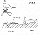
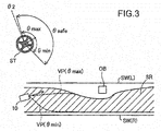
- Fig. 2 and Fig. 3 are diagrams illustrating the outline of the operation intervention control performed by the driving assisting ECU 100.
- Fig. 2 and Fig. 3 illustrate variations in steering angle of a steering wheel ST (where counterclockwise rotation is in a positive direction) included in the steering device 272 in correlation with the driving environment of the vehicle 10.
- the vehicle 10 runs from a left side of the drawing to a right side on a lane defined by a right side wall SW(R) and a left side wall SW(L), and an obstacle OB is present ahead of the vehicle 10.
- the illustrations of Fig. 2 and Fig. 3 also include an acceptable safety range SR that denotes a range in which the behavior of the vehicle 10 is to be kept, in order to ensure the safety of the vehicle 10.
- the driving assisting ECU 100 calculate an acceptable control input range ⁇ safe (more specifically, a minimum acceptable value ⁇ min and a maximum acceptable value ⁇ max of steering angle ⁇ ) that denotes a range of operation (steering angle ⁇ according to this embodiment) accepted at a present time t, in order to keep an estimated behavior of the vehicle 10 (path according to this embodiment) in the acceptable safety range SR over an estimation interval (time interval according to this embodiment).
- Fig. 2 and Fig. 3 illustrate an estimated path VP( ⁇ max ) of the vehicle 10 when the steering angle at the present time t is the maximum acceptable value ⁇ m ⁇ x and an estimated path VP( ⁇ min ) of the vehicle 10 when the steering angle at the present time t is the minimum acceptable value ⁇ min .
- the driving assisting ECU 100 does not make an operation intervention when the steering angle ⁇ at the present time t is equal to ⁇ 1 that is a value in the acceptable control input range ⁇ safe as in the example of Fig. 2 , whereas making an operation intervention when the steering angle ⁇ at the present time t is equal to ⁇ 2 that is a value out of the acceptable control input range ⁇ safe as in the example of Fig. 3 .
- Such operation intervention control performed by the driving assisting ECU 100 is not “emergency” operation intervention control that makes an operation intervention based on, for example, only a physical limit using a risk index such as a time to collision (TTC) but is rather “ordinary” operation intervention control that is triggered at a stage prior to an emergency state (i.e., in order to prevent an emergency state).
- TTC time to collision
- Driving action characteristic information DI indicating the driving action characteristic of each driver and vehicle characteristic information VI indicating the motion characteristics of the vehicle 10 are referred to in the procedure of estimating the path of the vehicle 10.
- Model driving action information MI indicating a model driver's driving action characteristic is referred to in the process of setting the acceptable safety range SR. These will be described later in detail.
- the driving assisting ECU 100 includes a model driving action information storage unit 110, an acceptable safety range setter 120, a vehicle characteristic information storage unit 130, a driving action characteristic information storage unit 140, a driving action characteristic information manager 150, an acceptable control input range calculator 160, an operation intervention determiner 170 and an operation intervention executor 180.
- the operation intervention executor 180 includes an intervention support input determiner 182.
- the model driving action information storage unit 110 of the driving assisting ECU 100 stores the model driving action information MI indicating the model driver's driving action characteristic.
- the acceptable safety range setter 120 refers to the model driving action information MI and sets the acceptable safety range SR.
- the vehicle characteristic information storage unit 130 stores the vehicle characteristic information VI indicating the motion characteristics of the vehicle 10.
- the driving action characteristic information manager 150 generates and manages the driving action characteristic information DI indicating the driving action characteristic of each driver.
- the driving action characteristic information storage unit 140 stores the driving action characteristic information DI.
- the acceptable control input range calculator 160 calculates the acceptable control input range ⁇ safe .
- the operation intervention determiner 170 determines whether an operation intervention is to be made or not.
- the operation intervention executor 180 makes an operation intervention when it is determined that the operation intervention is to be made.
- the intervention support input determiner 182 determines an intervention support input that denotes the degree of intervention when the operation intervention is to be made. The following describes the operation intervention control performed by the driving assisting ECU 100 more in detail.
- the driving action characteristic information DI stored in the driving action characteristic information storage unit 140 denotes information with regard to the driving action characteristic of each driver.
- the driving action characteristic denote an action characteristic when each driver drives the vehicle 10 and include, for example, a characteristic indicating which path the driver is likely to take at what velocity in a certain driving environment.
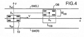
- Fig. 4 is a diagram illustrating one example of the driving environment of the vehicle 10.
- the vehicle 10 (its center of gravity) is located at coordinates (0,0) on a straight one-way road that is extended in an x-axis direction and moves straight at a velocity V toward a positive x ⁇ axis direction.
- a right side wall SW(R) is present on the right side of the vehicle 10
- a left side wall SW(L) is present on the left side of the vehicle 10.
- a lane is defined by the two side walls SW.
- a parking vehicle having a length L OB in the x ⁇ axis direction and a width W OB in a y-axis direction is present as an obstacle OB at coordinates (x c ,y c ).
- y wr ⁇ 3.5 (m)
- y wl 3.5 (m)
- x c 70 (m)
- y c 1.57 (m)
- L OB 4.80 (m)
- W OB 1.94 (m).
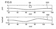
- Fig. 5 and Fig. 6 are diagrams illustrating examples of the driving action characteristics of respective drivers.
- the upper drawing of Fig. 5 illustrates a path curve D(A) indicating a driving truck of the vehicle 10 when a driver A drives the vehicle 10 in the driving environment shown in Fig. 4 .
- the lower drawing of Fig. 5 illustrates a yaw curve Y(A) indicating a variation in yaw of the vehicle 10 during such driving.
- Fig. 6 illustrates a path curve D(B) and a yaw curve Y(B) when a driver B different from the driver A drives the vehicle 10 in the driving environment shown in Fig. 4 .
- Fig. 5 and Fig. 6 illustrates a path curve D(B) and a yaw curve Y(B) when a driver B different from the driver A drives the vehicle 10 in the driving environment shown in Fig. 4 .
- the abscissa shows the coordinate in the x-axis direction
- the ordinate shows the coordinate in the y-axis direction in the upper drawing and the yaw angle (rad) of the vehicle 10 in the lower drawing.
- the path curve D and the yaw curve Y may differ by the driver even in the same driving environment.
- the driver B who performs the driving action shown in Fig. 6 has an earlier start timing of an action for avoiding the obstacle OB and has a smaller variation in yaw, compared with the driver A who performs the driving action shown in Fig. 5 . This means that the driver B has a driving action characteristic of avoiding the obstacle OB more gently.
- Each driver's obstacle avoiding action may be thought to explicitly indicate the driver's risk feeling against the obstacle. Accordingly a cause of the difference in each driver's obstacle avoiding action, i.e., the difference in driving action characteristic, may be attributed to the difference in each driver's risk feeling against the obstacle.
- This embodiment models each driver's risk feeling and expresses the modeled risk feeling as a potential function in parameter expression as one example of modeling the driving action characteristic. This is described concretely below.
- the attractive force potential function U g from the goal is expressed as a linear potential function going forward on the assumption that the goal is at infinity in the moving direction.
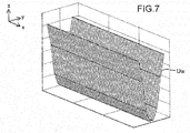
- the repulsive force potential function U w from the left and right boundaries is expressed by using a one-dimensional Gauss function on the assumption that the boundaries have infinite lengths.
- Fig. 7 illustrates one example of the repulsive force potential function U w from the left and right boundaries in the driving environment of Fig. 4 .
- the repulsive force potential function U c from the obstacle OB is expressed by using a twodimensional Gauss function.
- Fig. 8 illustrates one example of the repulsive force potential function U c from the obstacle OB in the driving environment of Fig. 4 .
- a z axis shows the magnitude of the potential function.
- the magnitude of the attractive force, the magnitude of the repulsive force, the range of influence and the like may be adjusted by changing the respective parameters in the three potential functions described above.
- the three potential functions are thus applicable to diverse situations, for example, different sizes of the obstacle OB or the respective drivers' different risk feelings. In the actual driving environment, a plurality of such factors are combined simultaneously.
- the driver's driving action may be expressed by using superposition of these three potential functions.
- a procedure of this embodiment estimates the respective parameter values of the potential functions using driving data observed when each driver drives the vehicle 10, in order to fit the above potential functions to each driver. More specifically, the procedure obtains coordinates (x i l , y i l ) and a velocity v(x i l , y i l ) of the vehicle 10 at each time during driving of the vehicle 10 in a predetermined driving environment, as driving data.
- 1 ⁇ 1, 2, ..., L ⁇ denotes a trial number
- i ⁇ 1, 2 ...
- n l denotes a data index
- n l denotes the number of data obtained in an 1-th trial.
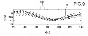
- Fig. 9 illustrates one example of a distribution of coordinates P of the vehicle 10 at respective times when a certain driver drives the vehicle 10 multiple times in the driving environment shown in Fig. 4 .
- the procedure subsequently lists up primary elements included in the driving environment and establishes a potential function U(x,y) that expresses the driving environment as their superposition, for example, as shown in Equation (4) given below:
- U x y U g x y + U w x y + ⁇ i N U ci x y
- a parameter estimation problem of the potential function is formulated by the following optimization problem.
- the vehicle 10 is provided with the radar unit 250 and the camera unit 260, so that the coordinates of the boundaries of the lane and the coordinates of the obstacle are known. Additionally, d(x i l , y i l ) denotes a steepest descent vector of the potential function U at the coordinates (x i l , y i l ).
- An evaluation function J in this optimization problem is a square sum of the difference between a measured velocity vector v and a slope vector d calculated from a potential field indicating the risk feeling.
- a route estimated from the potential field obtained as a result of this optimization is thus expected to be similar to the driver's avoidance route, and estimated parameters such as w ci , ⁇ cxi and ⁇ cyi are expected to quantitatively express the driver's risk feeling against an obstacle in the driving environment.
- the estimated parameters are considered as intrinsic to a target intention and a target obstacle, so that the same parameters may be used for similar obstacles even in different driving environments.
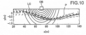
- Fig. 10 illustrates one example of a contour LC of an identified potential field of an obstacle. The shape of the contour LC may differ by the driver.
- the evaluation function in the optimization problem for identification of the parameters of the potential function is not limited to the function described above but may be another function.
- the driving action characteristic information manager 150 of the vehicle 10 accumulates driving data of the vehicle 10, estimates the respective parameter values of the above potential functions based on the accumulated driving data, generates driving action characteristic information DI for specifying the respective estimated parameter values and stores the generated driving action characteristic information DI in the driving action characteristic information storage unit 140.
- the driving action characteristic information manager 150 identifies each driver based on specification via a nonillustrated user interface or the like and accumulates the driving data with respect to each driver.
- driving action characteristic information DI indicating, for example, an average driver's driving action characteristic is stored in the driving action characteristic information storage unit 140.
- the driving action characteristic information DI is updated.
- the driving action characteristic information DI may be updated at regular intervals or at random times after that.
- the driving data corresponds to the behavior information of the claims.
- the following describes setting of the acceptable safety range SR by the acceptable safety range setter 120 (shown in Fig. 1 ).
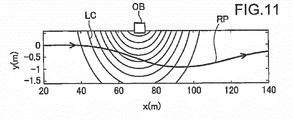
- a reference path RP is generated by using the driving action characteristic information DI.
- the reference path RP denotes a path of the vehicle 10 having a minimum risk potential.
- the reference path RP needs to be a path on which the vehicle 10 can actually run. In other words, the vehicle 10 has a non-holonomic constraint and a limitation in possible steering angle. Accordingly, the vehicle characteristic information VI (shown in Fig. 1 ) that is stored in the vehicle characteristic information storage unit 130 and that indicates the motion characteristics of the vehicle 10 is referred to in the process of generating the reference path RP.
- This optimization problem is a problem of searching for a front wheel steering angle and a condition that provide a minimum risk potential in a possible solution space by the vehicle motion characteristic models.
- the reference path RP is generated using this optimization problem by the following procedure. Repeating this procedure generates a route (x k ,yk) (k ⁇ ⁇ 1, 2, 3, ..., K ⁇ ) suitable for a potential field under constraint of the motion characteristic models of the vehicle 10, as the reference path RP.
- Fig. 11 illustrates one example of the generated reference path RP.
- the acceptable safety range SR is set by referring to the model driving action information MI stored in the model driving action information storage unit 110 (shown in Fig. 1 ).
- the model driving action information MI denotes information indicating a model driver's (for example, a driving instructor of a driving school) driving action characteristic and is information with regard to the respective parameter values of the above potential functions with regard to the model driver (i.e., the model driver's driving action characteristic information DI) according to this embodiment.
- the model driving action information MI corresponds to the specific driving action information of the claims.
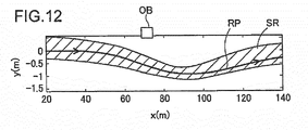
- Fig. 12 is a diagram illustrating one example of a method of setting the acceptable safety range SR.
- Fig. 12 illustrates a reference path RP generated by using the respective parameter values of the potential functions with regard to a model driver.
- This reference path RP denotes a model path of the vehicle 10 in a specific driving environment in which the reference path RP is generated.
- a range that includes this reference path RP and provides the reference path RP with some margins calculated by taking into account a distribution is set as the acceptable safety range SR.
- the acceptable safety range SR corresponds to the predetermined range of the claims.
- the acceptable control input range ⁇ safe denotes the range of steering angle (the minimum acceptable value ⁇ min and the maximum acceptable value ⁇ max of the steering angle ⁇ ) accepted at the present time t, in order to cause the path of the vehicle 10 estimated by referring to the driving action characteristic information DI and the vehicle characteristic information VI to be kept in the acceptable safety range SR over the estimation interval.
- the acceptable control input range calculator 160 solves the following acceptable control input range calculation problem from the viewpoint of constraint satisfaction, so as to set the acceptable control input range ⁇ safe .
- model driving action time t to t + K
- acceptable safety range SR time t to t + K
- the path of the vehicle by taking into account the driving action characteristic and the vehicle motion characteristics is kept in the acceptable safety range SR.
- the following describes operation intervention determination by the operation intervention determiner 170 (shown in Fig. 1 ) and operation intervention execution by the operation intervention executor 180.
- the operation intervention determiner 170 determines whether the steering angle ⁇ at the present time t is within the acceptable control input range ⁇ safe .
- the operation intervention determiner 170 determines that an operation intervention is not to be made when the steering angle ⁇ at the present time t is within the acceptable control input range ⁇ safe , whereas determining that an operation intervention is to be made when the steering angle ⁇ at the present time t is out of the acceptable control input range ⁇ safe .
- Fig. 13 is a diagram illustrating one example of a method of determining the intervention support input Ua.
- the intervention support input Ua is determined to be a predetermined fixed value, whether the steering angle ⁇ at the present time t is larger than the maximum acceptable value ⁇ max or the steering angle ⁇ at the present time t is smaller than the minimum acceptable value ⁇ min .
- This value is variably set according to the driving ability of each driver.
- an operation intervention is also made with the intervention support input Ua according to the steering angle ⁇ in transient areas ⁇ trn that are areas near to the respective boundaries of the acceptable control input range ⁇ safe .
- an operation intervention is not made when the steering angle ⁇ at the present moment t is in any area other than the transient areas ⁇ trn in the acceptable control input range ⁇ safe .
- the operation intervention executor 180 makes an operation intervention with regard to steering via the steering ECU 270 using the intervention support input Ua determined by the intervention support input determiner 182.
- Fig. 14 is a flowchart showing a flow of operation intervention control process by the driving assisting ECU 100 according to the embodiment.
- the driving assisting ECU 100 first obtains the detection results of lane boundaries and any obstacle and the information with regard to the driving operation, the vehicle speed, the yaw rate and the like from the driving operation detector 210, the vehicle speed sensor 220, the yaw rate sensor 230, the radar unit 250, the camera unit 260 and the like to grasp the driving environment of the vehicle 10 (S110).
- the acceptable safety range setter 120 subsequently sets the acceptable safety range SR (shown in Fig. 12 ) according to the grasped driving environment using the model driving action information MI (S120).
- the acceptable control input range calculator 160 subsequently calculates the acceptable control input range ⁇ safe (shown in Fig. 2 and Fig. 3 ) by using the driving action characteristic information DI and the vehicle characteristic information VI (S130).
- the operation intervention determiner 170 determines whether the operation (steering angle ⁇ ) at the present time t is within the acceptable control input range ⁇ safe in real time (S140). When it is determined that the steering angle ⁇ at the present time t is out of the acceptable control input range ⁇ safe (S140: NO), the intervention support input determiner 182 determines the intervention support input Ua (S150) and the operation intervention executor 180 makes an operation intervention using the determined intervention support input Ua (S160).
- the operation intervention determiner 170 determines whether the steering angle ⁇ at the present time t is within the transient area ⁇ tra (shown in Fig. 13 ) (S142). When it is determined that the steering angle ⁇ at the present time t is within the transient area ⁇ tra (S142: YES), the intervention support input determiner 182 determines the intervention support input Ua (S150) and the operation intervention executor 180 makes an operation intervention using the determined intervention support input Ua (S160).
- the driving assisting ECU 100 repeatedly performs the processing of S110 to S160 described above unless receiving a processing termination instruction (S170: NO).
- the driving assisting ECU 100 terminates the operation intervention control process when receiving the processing termination instruction (S170: YES).
- the acceptable safety range setter 120 sets the acceptable safety range SR that is a range with regard to the path of the vehicle 10.
- the acceptable control input range calculator 160 calculates the acceptable control input range ⁇ safe that is the range of the steering angle ⁇ accepted at the present time t, in order to cause the path of the vehicle 10 estimated by using the driving action characteristic information DI indicating the driving action characteristic of the driver of the vehicle 10 to be kept in the acceptable safety range SR over the estimation interval.
- the operation intervention determiner 170 determines whether the steering angle ⁇ at the present time t is within the acceptable control input range ⁇ safe .
- the operation intervention executor 180 makes an operation intervention with regard to steering.
- the driving assisting ECU 100 of this embodiment ensures the safety by an operation intervention and also further reduces the driver's feeling of strangeness by the operation intervention by using the driving action characteristic information DI for path estimation of the vehicle 10 for the purpose of calculation of the acceptable control input range ⁇ safe , compared with the prior art configuration that employs a uniform determination technique to determine whether an operation intervention is to be made or not.
- the driving assisting ECU 100 of this embodiment sets the acceptable safety range SR by using the model driving action information MI that is the model driver's driving action characteristic information DI. This configuration makes an operation intervention to guide the driver to a model driving action and thereby more reliably ensures the safety.
- the driving action characteristic information manager 150 accumulates the driving data indicating the behavior of the vehicle 10 (behavior information) in correlation with the driver during driving of the vehicle 10 and generates the driving action characteristic information DI using the accumulated driving data.
- This configuration allows for generation of the driving action characteristic information DI that reflects the driver's driving action characteristic with high accuracy and thereby more effectively reduces the driver's feeling of strangeness by an operation intervention.
- the driving assisting ECU 100 of this embodiment also uses the vehicle characteristic information VI indicating the motion characteristics of the vehicle 10 for path estimation of the vehicle 10 for the purpose of calculation of the acceptable control input range ⁇ safe .
- This configuration enables an appropriate path to be estimated by taking into account the motion characteristics of the vehicle 10 and thereby satisfies the required safety and reduction of the feeling of strangeness at high levels.
- the intervention support input determiner 182 variably determines the intervention support input Ua. This configuration enables an operation intervention to be made using the appropriate intervention support input Ua according to the driver's driving ability and the like.
- the path of the vehicle 10 estimated for calculation of the acceptable control input range ⁇ safe by the acceptable control input range calculator 160 is a path without an operation intervention. This configuration allows for path estimation with the higher accuracy compared with path estimation with an operation intervention, and thereby results in determining whether an operation intervention is to be made or not with high accuracy.
- the above embodiment describes the operation intervention control with regard to steering of the vehicle 10.
- the present invention is also applicable to, for example, operation intervention control with regard to braking of the vehicle 10 as in the case of, for example, stopping at a blind intersection.
- the present invention may be applied to operation intervention control with regard to braking, for example, as described below.
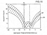
- Fig. 15 is a diagram illustrating one example of the method of setting the acceptable safety range SR according to the modification.
- the ordinate shows the velocity of the vehicle 10
- the abscissa shows the distance from an intersection.
- FIG. 15 shows a reference path RP generated by using driving data of a model driver and an acceptable safety range SR with regard to the vehicle speed that is set by providing the reference path RP with some margins.
- the procedure calculates an operation (depression angle of a brake pedal) to keep the vehicle speed in the acceptable safety range SR over an estimation interval, as the acceptable control input range ⁇ safe (S130 in Fig. 14 ).
- the procedure determines whether an operation intervention with regard to braking is to be made or not, based on whether the operation (depression angle of the brake pedal) at the present time t is within the acceptable control input range ⁇ safe (S140 in Fig. 14 ).
- the procedure determines a pedal force applied to the brake pedal as the intervention support input Ua (S150 in Fig. 14 ) and makes an operation intervention using the determined intervention support input Ua via the brake ECU 280 (S160 in Fig. 14 ).
- Operation intervention control with regard to acceleration may be performed in addition to the operation intervention control with regard to braking or in place of the operation intervention control with regard to braking. For example, when it is determined that the vehicle speed is lower than the acceptable safety range SR in the estimation interval, an operation intervention may be made to increase the depression angle of an accelerator pedal.
- the aspect of the present invention may make not only an operation intervention with regard to steering but an operation intervention with regard to braking or acceleration, so as to further reduce the driver's feeling of strangeness, while ensuring safety by the operation intervention.
- the configuration of the vehicle 10 described in the above embodiment is only illustrative. Part of the components described above may be omitted from the vehicle 10, or components other than those described above may be added to the vehicle 10.
- the model representing the driver's driving action characteristic described in the above embodiment is only illustrative, and another model, for example, a hybrid dynamic system model may be employed.
- the model representing the motion characteristics of the vehicle described in the above embodiment is only illustrative, and another model, for example, a steady circular turning model or a constant velocity model.
- the intervention support input Ua when the steering angle is out of the acceptable control input range ⁇ safe , the intervention support input Ua is determined to be a predetermined fixed value (as shown in Fig. 13 ). According to a modification, the intervention support input Ua may be varied according to the steering angle ⁇ at the present time. According to the above embodiment, an operation intervention is also made in the transient areas ⁇ tra in the acceptable control input range ⁇ safe . According to a modification, an operation intervention is not made at all in the acceptable control input range ⁇ safe .
- the acceptable safety range SR is set by using the model driving action information MI that is the model driver's driving action characteristic information DI.
- the acceptable safety range SR may be set by using one specific driver's or multiple drivers' driving action information DI. It is also not essential to use the driving action characteristic information DI for setting the acceptable safety range SR. Any method may be employed to set the acceptable safety range SR as long as the acceptable safety range SR is set as a range in which the behavior of the vehicle 10 is to be kept, in order to ensure the safety of the vehicle 10.
- the estimation interval is a time interval.
- the estimation interval may, however, be a distance interval.
- the driving assisting ECU 100 performs the ordinary operation intervention control that is triggered at the stage prior to the emergency state.
- the driving assisting ECU 100 may additionally perform emergency operation intervention control that makes an operation intervention based on, for example, only a physical limit using a risk index such as a time to collision (TTC).
- TTC time to collision
- 10 vehicle, 100: driving assisting ECU, 110: model driving action information storage unit, 120: acceptable safety range setter, 130: vehicle characteristic information storage unit, 140: driving action characteristic information storage unit, 150: driving action characteristic information manager, 160: acceptable control input range calculator, 170: operation intervention determiner, 180: operation intervention executor, 182: intervention support input determiner, 210: driving operation detector, 220: vehicle speed sensor, 230: yaw rate sensor, 240: GPS, 250: radar unit, 260: camera unit, 270: steering ECU, 272: steering device, 280: brake ECU, 282: brake device, DI: driving action characteristic information, MI: model driving action information, VI: vehicle characteristic information
Applications Claiming Priority (2)
| Application Number | Priority Date | Filing Date | Title |
|---|---|---|---|
| JP2015065761A JP6315827B2 (ja) | 2015-03-27 | 2015-03-27 | 運転支援装置 |
| PCT/JP2016/057927 WO2016158341A1 (ja) | 2015-03-27 | 2016-03-14 | 運転支援装置 |
Publications (3)
| Publication Number | Publication Date |
|---|---|
| EP3276589A1 EP3276589A1 (en) | 2018-01-31 |
| EP3276589A4 EP3276589A4 (en) | 2019-01-02 |
| EP3276589B1 true EP3276589B1 (en) | 2021-11-17 |
Family
ID=57005664
Family Applications (1)
| Application Number | Title | Priority Date | Filing Date |
|---|---|---|---|
| EP16772224.8A Active EP3276589B1 (en) | 2015-03-27 | 2016-03-14 | Driving assistance device |
Country Status (5)
| Country | Link |
|---|---|
| US (1) | US20180118200A1 (ja) |
| EP (1) | EP3276589B1 (ja) |
| JP (1) | JP6315827B2 (ja) |
| CN (1) | CN107408344B (ja) |
| WO (1) | WO2016158341A1 (ja) |
Families Citing this family (11)
| Publication number | Priority date | Publication date | Assignee | Title |
|---|---|---|---|---|
| JP6801227B2 (ja) | 2015-09-02 | 2020-12-16 | カシオ計算機株式会社 | 電子時計 |
| JPWO2018131090A1 (ja) * | 2017-01-11 | 2019-11-07 | 本田技研工業株式会社 | 車両制御装置、車両制御方法、および車両制御プログラム |
| JP6533343B2 (ja) * | 2017-04-25 | 2019-06-26 | 博隆 北川 | 重力場理論を使用した車の自動運転計算方法 |
| JP6845083B2 (ja) * | 2017-05-18 | 2021-03-17 | トヨタ自動車株式会社 | 運転支援装置 |
| JP2019028524A (ja) * | 2017-07-26 | 2019-02-21 | 本田技研工業株式会社 | 制御装置 |
| KR102005900B1 (ko) * | 2017-11-30 | 2019-08-01 | 주식회사 만도 | 차량의 전방 및 측방 충돌 가능성을 기초로 어시스트 토크를 조정하는 전동식 조향 장치 및 방법 |
| US11400927B2 (en) * | 2018-01-29 | 2022-08-02 | Ford Global Technologies, Llc | Collision avoidance and mitigation |
| WO2021065196A1 (en) * | 2019-10-03 | 2021-04-08 | Mitsubishi Electric Corporation | Method and system for trajectory optimization for nonlinear robotic systems with geometric constraints |
| US11527073B2 (en) * | 2019-11-15 | 2022-12-13 | Honda Motor Co., Ltd. | System and method for providing an interpretable and unified representation for trajectory prediction |
| JP7314883B2 (ja) * | 2020-08-27 | 2023-07-26 | いすゞ自動車株式会社 | 自動運転装置 |
| JP7384258B1 (ja) | 2022-09-26 | 2023-11-21 | いすゞ自動車株式会社 | 自動運転装置 |
Family Cites Families (14)
| Publication number | Priority date | Publication date | Assignee | Title |
|---|---|---|---|---|
| JP4062310B2 (ja) * | 2005-02-07 | 2008-03-19 | 日産自動車株式会社 | 運転意図推定装置、車両用運転操作補助装置および車両用運転操作補助装置を備えた車両 |
| JP4466571B2 (ja) * | 2005-05-12 | 2010-05-26 | 株式会社デンソー | ドライバ状態検出装置、車載警報装置、運転支援システム |
| WO2007077867A1 (ja) * | 2005-12-28 | 2007-07-12 | National University Corporation Nagoya University | 運転行動推定装置、運転支援装置、車両評価システム、ドライバモデル作成装置、及び運転行動判定装置 |
| JP5205997B2 (ja) * | 2008-02-06 | 2013-06-05 | 日産自動車株式会社 | 車両用運転操作支援装置 |
| JP2009220605A (ja) * | 2008-03-13 | 2009-10-01 | Aisin Aw Co Ltd | 運転支援装置、運転支援方法および運転支援プログラム |
| JP4541428B2 (ja) * | 2008-05-28 | 2010-09-08 | ヒロセ電機株式会社 | 平型導体用電気コネクタ |
| JP5043760B2 (ja) * | 2008-06-17 | 2012-10-10 | 日産自動車株式会社 | 車両用障害物回避支援装置及び車両用障害物回避支援方法 |
| JP5200732B2 (ja) * | 2008-07-29 | 2013-06-05 | 日産自動車株式会社 | 走行制御装置、及び走行制御方法 |
| JP5168420B2 (ja) * | 2009-12-18 | 2013-03-21 | トヨタ自動車株式会社 | 走行制御装置 |
| DE102010045694A1 (de) * | 2010-09-16 | 2012-03-22 | Daimler Ag | Verfahren zur Vermeidung von Kollisionen eines Fahrzeugs mit Hindernissen |
| JP5742184B2 (ja) * | 2010-11-16 | 2015-07-01 | トヨタ自動車株式会社 | 運転支援装置 |
| DE102012010130A1 (de) * | 2012-05-23 | 2012-12-13 | Daimler Ag | Verfahren zum Ermitteln von kollisionsgefährdenden Lenkwinkelwerteneines Kraftfahrzeuges unter Berücksichtigung eines dynamischen Abstandsgrenzwerts |
| US10692370B2 (en) * | 2014-03-03 | 2020-06-23 | Inrix, Inc. | Traffic obstruction detection |
| US9248834B1 (en) * | 2014-10-02 | 2016-02-02 | Google Inc. | Predicting trajectories of objects based on contextual information |
-
2015
- 2015-03-27 JP JP2015065761A patent/JP6315827B2/ja active Active
-
2016
- 2016-03-14 US US15/561,093 patent/US20180118200A1/en not_active Abandoned
- 2016-03-14 CN CN201680018276.XA patent/CN107408344B/zh active Active
- 2016-03-14 EP EP16772224.8A patent/EP3276589B1/en active Active
- 2016-03-14 WO PCT/JP2016/057927 patent/WO2016158341A1/ja active Application Filing
Also Published As
| Publication number | Publication date |
|---|---|
| WO2016158341A1 (ja) | 2016-10-06 |
| EP3276589A4 (en) | 2019-01-02 |
| EP3276589A1 (en) | 2018-01-31 |
| CN107408344B (zh) | 2021-07-06 |
| CN107408344A (zh) | 2017-11-28 |
| JP2016186683A (ja) | 2016-10-27 |
| US20180118200A1 (en) | 2018-05-03 |
| JP6315827B2 (ja) | 2018-04-25 |
Similar Documents
| Publication | Publication Date | Title |
|---|---|---|
| EP3276589B1 (en) | Driving assistance device | |
| US9566981B2 (en) | Method and system for post-collision manoeuvre planning and vehicle equipped with such system | |
| US8849515B2 (en) | Steering assist in driver initiated collision avoidance maneuver | |
| EP1332910B1 (en) | Method and system for vehicle operator assistance improvement | |
| EP3699047A1 (en) | Vehicle control apparatus | |
| EP2750118B1 (en) | Driving support apparatus and driving support method | |
| US9159023B2 (en) | System for predicting a driver's intention to change lanes | |
| EP3699049A1 (en) | Vehicle control device | |
| EP3741639A1 (en) | Vehicle control device | |
| EP2757540B1 (en) | Driving assistance device and driving assistance method | |
| EP3715204A1 (en) | Vehicle control device | |
| EP2918467A1 (en) | Drive assist device and method, collision prediction device and method, and alerting device and method | |
| US20140081542A1 (en) | System and method for preventing vehicle from rolling over in curved lane | |
| US20150142299A1 (en) | Steering risk decision system and method for driving narrow roads | |
| EP3741638A1 (en) | Vehicle control device | |
| EP3738849A1 (en) | Vehicle control device | |
| CN106608259B (zh) | 自动紧急制动装置和方法 | |
| EP3666612A1 (en) | Vehicle control device | |
| Park et al. | A vehicle speed harmonization strategy for minimizing inter-vehicle crash risks | |
| CN113911111B (zh) | 车辆碰撞检测方法、系统、电子设备以及存储介质 | |
| JP2010039718A (ja) | 車両制御装置、車両制御方法および車両制御処理プログラム | |
| CN113561992A (zh) | 自动驾驶车辆轨迹生成方法、装置、终端设备及介质 | |
| CN112542061A (zh) | 基于车联网的借道超车控制方法、装置、系统及存储介质 | |
| EP2364891B1 (en) | Method for threat assessment in a vehicle | |
| JP2023512548A (ja) | 車両を制御する方法 |
Legal Events
| Date | Code | Title | Description |
|---|---|---|---|
| STAA | Information on the status of an ep patent application or granted ep patent |
Free format text: STATUS: THE INTERNATIONAL PUBLICATION HAS BEEN MADE |
|
| PUAI | Public reference made under article 153(3) epc to a published international application that has entered the european phase |
Free format text: ORIGINAL CODE: 0009012 |
|
| STAA | Information on the status of an ep patent application or granted ep patent |
Free format text: STATUS: REQUEST FOR EXAMINATION WAS MADE |
|
| 17P | Request for examination filed |
Effective date: 20171025 |
|
| AK | Designated contracting states |
Kind code of ref document: A1 Designated state(s): AL AT BE BG CH CY CZ DE DK EE ES FI FR GB GR HR HU IE IS IT LI LT LU LV MC MK MT NL NO PL PT RO RS SE SI SK SM TR |
|
| AX | Request for extension of the european patent |
Extension state: BA ME |
|
| DAV | Request for validation of the european patent (deleted) | ||
| DAX | Request for extension of the european patent (deleted) | ||
| A4 | Supplementary search report drawn up and despatched |
Effective date: 20181205 |
|
| RIC1 | Information provided on ipc code assigned before grant |
Ipc: B62D 6/00 20060101ALI20181129BHEP Ipc: B62D 109/00 20060101ALI20181129BHEP Ipc: B60W 30/09 20120101ALI20181129BHEP Ipc: B60W 40/09 20120101ALI20181129BHEP Ipc: B60W 30/14 20060101ALI20181129BHEP Ipc: B62D 101/00 20060101ALI20181129BHEP Ipc: G08G 1/16 20060101AFI20181129BHEP Ipc: B62D 113/00 20060101ALI20181129BHEP Ipc: B62D 137/00 20060101ALI20181129BHEP |
|
| GRAP | Despatch of communication of intention to grant a patent |
Free format text: ORIGINAL CODE: EPIDOSNIGR1 |
|
| STAA | Information on the status of an ep patent application or granted ep patent |
Free format text: STATUS: GRANT OF PATENT IS INTENDED |
|
| INTG | Intention to grant announced |
Effective date: 20210210 |
|
| GRAJ | Information related to disapproval of communication of intention to grant by the applicant or resumption of examination proceedings by the epo deleted |
Free format text: ORIGINAL CODE: EPIDOSDIGR1 |
|
| STAA | Information on the status of an ep patent application or granted ep patent |
Free format text: STATUS: REQUEST FOR EXAMINATION WAS MADE |
|
| GRAP | Despatch of communication of intention to grant a patent |
Free format text: ORIGINAL CODE: EPIDOSNIGR1 |
|
| STAA | Information on the status of an ep patent application or granted ep patent |
Free format text: STATUS: GRANT OF PATENT IS INTENDED |
|
| INTC | Intention to grant announced (deleted) | ||
| INTG | Intention to grant announced |
Effective date: 20210719 |
|
| GRAS | Grant fee paid |
Free format text: ORIGINAL CODE: EPIDOSNIGR3 |
|
| GRAA | (expected) grant |
Free format text: ORIGINAL CODE: 0009210 |
|
| STAA | Information on the status of an ep patent application or granted ep patent |
Free format text: STATUS: THE PATENT HAS BEEN GRANTED |
|
| AK | Designated contracting states |
Kind code of ref document: B1 Designated state(s): AL AT BE BG CH CY CZ DE DK EE ES FI FR GB GR HR HU IE IS IT LI LT LU LV MC MK MT NL NO PL PT RO RS SE SI SK SM TR |
|
| REG | Reference to a national code |
Ref country code: GB Ref legal event code: FG4D |
|
| REG | Reference to a national code |
Ref country code: IE Ref legal event code: FG4D |
|
| REG | Reference to a national code |
Ref country code: DE Ref legal event code: R096 Ref document number: 602016066353 Country of ref document: DE |
|
| REG | Reference to a national code |
Ref country code: AT Ref legal event code: REF Ref document number: 1448722 Country of ref document: AT Kind code of ref document: T Effective date: 20211215 |
|
| REG | Reference to a national code |
Ref country code: LT Ref legal event code: MG9D |
|
| REG | Reference to a national code |
Ref country code: NL Ref legal event code: MP Effective date: 20211117 |
|
| REG | Reference to a national code |
Ref country code: AT Ref legal event code: MK05 Ref document number: 1448722 Country of ref document: AT Kind code of ref document: T Effective date: 20211117 |
|
| PG25 | Lapsed in a contracting state [announced via postgrant information from national office to epo] |
Ref country code: RS Free format text: LAPSE BECAUSE OF FAILURE TO SUBMIT A TRANSLATION OF THE DESCRIPTION OR TO PAY THE FEE WITHIN THE PRESCRIBED TIME-LIMIT Effective date: 20211117 Ref country code: LT Free format text: LAPSE BECAUSE OF FAILURE TO SUBMIT A TRANSLATION OF THE DESCRIPTION OR TO PAY THE FEE WITHIN THE PRESCRIBED TIME-LIMIT Effective date: 20211117 Ref country code: FI Free format text: LAPSE BECAUSE OF FAILURE TO SUBMIT A TRANSLATION OF THE DESCRIPTION OR TO PAY THE FEE WITHIN THE PRESCRIBED TIME-LIMIT Effective date: 20211117 Ref country code: BG Free format text: LAPSE BECAUSE OF FAILURE TO SUBMIT A TRANSLATION OF THE DESCRIPTION OR TO PAY THE FEE WITHIN THE PRESCRIBED TIME-LIMIT Effective date: 20220217 Ref country code: AT Free format text: LAPSE BECAUSE OF FAILURE TO SUBMIT A TRANSLATION OF THE DESCRIPTION OR TO PAY THE FEE WITHIN THE PRESCRIBED TIME-LIMIT Effective date: 20211117 |
|
| PG25 | Lapsed in a contracting state [announced via postgrant information from national office to epo] |
Ref country code: IS Free format text: LAPSE BECAUSE OF FAILURE TO SUBMIT A TRANSLATION OF THE DESCRIPTION OR TO PAY THE FEE WITHIN THE PRESCRIBED TIME-LIMIT Effective date: 20220317 Ref country code: SE Free format text: LAPSE BECAUSE OF FAILURE TO SUBMIT A TRANSLATION OF THE DESCRIPTION OR TO PAY THE FEE WITHIN THE PRESCRIBED TIME-LIMIT Effective date: 20211117 Ref country code: PT Free format text: LAPSE BECAUSE OF FAILURE TO SUBMIT A TRANSLATION OF THE DESCRIPTION OR TO PAY THE FEE WITHIN THE PRESCRIBED TIME-LIMIT Effective date: 20220317 Ref country code: PL Free format text: LAPSE BECAUSE OF FAILURE TO SUBMIT A TRANSLATION OF THE DESCRIPTION OR TO PAY THE FEE WITHIN THE PRESCRIBED TIME-LIMIT Effective date: 20211117 Ref country code: NO Free format text: LAPSE BECAUSE OF FAILURE TO SUBMIT A TRANSLATION OF THE DESCRIPTION OR TO PAY THE FEE WITHIN THE PRESCRIBED TIME-LIMIT Effective date: 20220217 Ref country code: NL Free format text: LAPSE BECAUSE OF FAILURE TO SUBMIT A TRANSLATION OF THE DESCRIPTION OR TO PAY THE FEE WITHIN THE PRESCRIBED TIME-LIMIT Effective date: 20211117 Ref country code: LV Free format text: LAPSE BECAUSE OF FAILURE TO SUBMIT A TRANSLATION OF THE DESCRIPTION OR TO PAY THE FEE WITHIN THE PRESCRIBED TIME-LIMIT Effective date: 20211117 Ref country code: HR Free format text: LAPSE BECAUSE OF FAILURE TO SUBMIT A TRANSLATION OF THE DESCRIPTION OR TO PAY THE FEE WITHIN THE PRESCRIBED TIME-LIMIT Effective date: 20211117 Ref country code: GR Free format text: LAPSE BECAUSE OF FAILURE TO SUBMIT A TRANSLATION OF THE DESCRIPTION OR TO PAY THE FEE WITHIN THE PRESCRIBED TIME-LIMIT Effective date: 20220218 Ref country code: ES Free format text: LAPSE BECAUSE OF FAILURE TO SUBMIT A TRANSLATION OF THE DESCRIPTION OR TO PAY THE FEE WITHIN THE PRESCRIBED TIME-LIMIT Effective date: 20211117 |
|
| PG25 | Lapsed in a contracting state [announced via postgrant information from national office to epo] |
Ref country code: SM Free format text: LAPSE BECAUSE OF FAILURE TO SUBMIT A TRANSLATION OF THE DESCRIPTION OR TO PAY THE FEE WITHIN THE PRESCRIBED TIME-LIMIT Effective date: 20211117 Ref country code: SK Free format text: LAPSE BECAUSE OF FAILURE TO SUBMIT A TRANSLATION OF THE DESCRIPTION OR TO PAY THE FEE WITHIN THE PRESCRIBED TIME-LIMIT Effective date: 20211117 Ref country code: RO Free format text: LAPSE BECAUSE OF FAILURE TO SUBMIT A TRANSLATION OF THE DESCRIPTION OR TO PAY THE FEE WITHIN THE PRESCRIBED TIME-LIMIT Effective date: 20211117 Ref country code: EE Free format text: LAPSE BECAUSE OF FAILURE TO SUBMIT A TRANSLATION OF THE DESCRIPTION OR TO PAY THE FEE WITHIN THE PRESCRIBED TIME-LIMIT Effective date: 20211117 Ref country code: DK Free format text: LAPSE BECAUSE OF FAILURE TO SUBMIT A TRANSLATION OF THE DESCRIPTION OR TO PAY THE FEE WITHIN THE PRESCRIBED TIME-LIMIT Effective date: 20211117 Ref country code: CZ Free format text: LAPSE BECAUSE OF FAILURE TO SUBMIT A TRANSLATION OF THE DESCRIPTION OR TO PAY THE FEE WITHIN THE PRESCRIBED TIME-LIMIT Effective date: 20211117 |
|
| REG | Reference to a national code |
Ref country code: DE Ref legal event code: R097 Ref document number: 602016066353 Country of ref document: DE |
|
| PLBE | No opposition filed within time limit |
Free format text: ORIGINAL CODE: 0009261 |
|
| STAA | Information on the status of an ep patent application or granted ep patent |
Free format text: STATUS: NO OPPOSITION FILED WITHIN TIME LIMIT |
|
| 26N | No opposition filed |
Effective date: 20220818 |
|
| PG25 | Lapsed in a contracting state [announced via postgrant information from national office to epo] |
Ref country code: MC Free format text: LAPSE BECAUSE OF FAILURE TO SUBMIT A TRANSLATION OF THE DESCRIPTION OR TO PAY THE FEE WITHIN THE PRESCRIBED TIME-LIMIT Effective date: 20211117 Ref country code: AL Free format text: LAPSE BECAUSE OF FAILURE TO SUBMIT A TRANSLATION OF THE DESCRIPTION OR TO PAY THE FEE WITHIN THE PRESCRIBED TIME-LIMIT Effective date: 20211117 |
|
| REG | Reference to a national code |
Ref country code: CH Ref legal event code: PL |
|
| GBPC | Gb: european patent ceased through non-payment of renewal fee |
Effective date: 20220314 |
|
| PG25 | Lapsed in a contracting state [announced via postgrant information from national office to epo] |
Ref country code: SI Free format text: LAPSE BECAUSE OF FAILURE TO SUBMIT A TRANSLATION OF THE DESCRIPTION OR TO PAY THE FEE WITHIN THE PRESCRIBED TIME-LIMIT Effective date: 20211117 |
|
| REG | Reference to a national code |
Ref country code: BE Ref legal event code: MM Effective date: 20220331 |
|
| PG25 | Lapsed in a contracting state [announced via postgrant information from national office to epo] |
Ref country code: LU Free format text: LAPSE BECAUSE OF NON-PAYMENT OF DUE FEES Effective date: 20220314 Ref country code: LI Free format text: LAPSE BECAUSE OF NON-PAYMENT OF DUE FEES Effective date: 20220331 Ref country code: IE Free format text: LAPSE BECAUSE OF NON-PAYMENT OF DUE FEES Effective date: 20220314 Ref country code: GB Free format text: LAPSE BECAUSE OF NON-PAYMENT OF DUE FEES Effective date: 20220314 Ref country code: FR Free format text: LAPSE BECAUSE OF NON-PAYMENT OF DUE FEES Effective date: 20220331 Ref country code: CH Free format text: LAPSE BECAUSE OF NON-PAYMENT OF DUE FEES Effective date: 20220331 |
|
| PG25 | Lapsed in a contracting state [announced via postgrant information from national office to epo] |
Ref country code: BE Free format text: LAPSE BECAUSE OF NON-PAYMENT OF DUE FEES Effective date: 20220331 |
|
| PG25 | Lapsed in a contracting state [announced via postgrant information from national office to epo] |
Ref country code: IT Free format text: LAPSE BECAUSE OF FAILURE TO SUBMIT A TRANSLATION OF THE DESCRIPTION OR TO PAY THE FEE WITHIN THE PRESCRIBED TIME-LIMIT Effective date: 20211117 |
|
| PGFP | Annual fee paid to national office [announced via postgrant information from national office to epo] |
Ref country code: DE Payment date: 20230323 Year of fee payment: 8 |
|
| PG25 | Lapsed in a contracting state [announced via postgrant information from national office to epo] |
Ref country code: HU Free format text: LAPSE BECAUSE OF FAILURE TO SUBMIT A TRANSLATION OF THE DESCRIPTION OR TO PAY THE FEE WITHIN THE PRESCRIBED TIME-LIMIT; INVALID AB INITIO Effective date: 20160314 |