WO2011065141A1 - 噛合チェーン式垂直搬送機 - Google Patents
噛合チェーン式垂直搬送機 Download PDFInfo
- Publication number
- WO2011065141A1 WO2011065141A1 PCT/JP2010/068048 JP2010068048W WO2011065141A1 WO 2011065141 A1 WO2011065141 A1 WO 2011065141A1 JP 2010068048 W JP2010068048 W JP 2010068048W WO 2011065141 A1 WO2011065141 A1 WO 2011065141A1
- Authority
- WO
- WIPO (PCT)
- Prior art keywords
- pair
- meshing
- type vertical
- lifting table
- chains
- Prior art date
- Legal status (The legal status is an assumption and is not a legal conclusion. Google has not performed a legal analysis and makes no representation as to the accuracy of the status listed.)
- Ceased
Links
Images



Classifications
-
- F—MECHANICAL ENGINEERING; LIGHTING; HEATING; WEAPONS; BLASTING
- F16—ENGINEERING ELEMENTS AND UNITS; GENERAL MEASURES FOR PRODUCING AND MAINTAINING EFFECTIVE FUNCTIONING OF MACHINES OR INSTALLATIONS; THERMAL INSULATION IN GENERAL
- F16G—BELTS, CABLES, OR ROPES, PREDOMINANTLY USED FOR DRIVING PURPOSES; CHAINS; FITTINGS PREDOMINANTLY USED THEREFOR
- F16G13/00—Chains
- F16G13/18—Chains having special overall characteristics
- F16G13/20—Chains having special overall characteristics stiff; Push-pull chains
-
- B—PERFORMING OPERATIONS; TRANSPORTING
- B66—HOISTING; LIFTING; HAULING
- B66F—HOISTING, LIFTING, HAULING OR PUSHING, NOT OTHERWISE PROVIDED FOR, e.g. DEVICES WHICH APPLY A LIFTING OR PUSHING FORCE DIRECTLY TO THE SURFACE OF A LOAD
- B66F13/00—Common constructional features or accessories
- B66F13/005—Thrust chain devices
-
- B—PERFORMING OPERATIONS; TRANSPORTING
- B65—CONVEYING; PACKING; STORING; HANDLING THIN OR FILAMENTARY MATERIAL
- B65G—TRANSPORT OR STORAGE DEVICES, e.g. CONVEYORS FOR LOADING OR TIPPING, SHOP CONVEYOR SYSTEMS OR PNEUMATIC TUBE CONVEYORS
- B65G47/00—Article or material-handling devices associated with conveyors; Methods employing such devices
- B65G47/52—Devices for transferring articles or materials between conveyors i.e. discharging or feeding devices
- B65G47/56—Devices for transferring articles or materials between conveyors i.e. discharging or feeding devices to or from inclined or vertical conveyor sections
- B65G47/57—Devices for transferring articles or materials between conveyors i.e. discharging or feeding devices to or from inclined or vertical conveyor sections for articles
Definitions
- the present invention is a vertical transfer machine that moves a workpiece up and down using manufacturing equipment in various manufacturing fields, transfer equipment in a transport field, and the like, and in particular, a mesh chain type vertical transport machine that employs a mesh chain as a drive medium for lifting and lowering operations.
- a mesh chain type vertical transport machine that employs a mesh chain as a drive medium for lifting and lowering operations.
- the carriage is suspended by a wire chain or the like and is driven up and down by a motor. Therefore, the wire chain or the like may be excessively stretched, and the number of rotations of the motor Even if the control is performed, there is a problem that the carriage stop position shifts and hinders the conveyance work.
- the carriage is suspended by a wire chain or other strip and driven to move up and down, so that the disengagement of the chain causes rolling and pitching of the wire chain and other strips, so that the workpiece mounted during lifting and transporting There was a problem of becoming unstable.
- the present invention solves the conventional problems. That is, the object of the present invention is to prevent the rolling and pitching of the lifting table and to reliably and stably convey the workpiece vertically and save space. Another object of the present invention is to provide a meshing chain type vertical transfer machine that realizes simple maintenance work such as cleaning work of a lifting area and replacement work of lifting parts.
- the present invention guides and guides a lifting table on which a work is mounted, a pair of meshing chains that support the center of the bottom surface of the lifting table to drive the lifting table so that the lifting table can be raised and lowered, and both side surfaces of the lifting table
- An engagement chain type vertical conveying machine comprising a pair of guide poles, a drive sprocket that drives the pair of engagement chains so as to be movable up and down, and a drive motor that supplies a drive force to the drive sprocket, wherein the pair of engagement chains includes
- the guide rollers are configured so as to be rigidly integrated with each other in a state of being opposed to each other and being disengaged from each other and to be freely branched, and the guide roller that rolls along the guide pole while holding the guide pole is moved up and down.
- the clamping direction of the pair of guide rollers facing the guide pole is in a meshing direction in which the pair of meshing chains are meshed with each other.
- the guide pole is composed of a cylindrical body
- the guide roller is composed of a drum roller.
- the drive sprocket is provided at a rigid position where the pair of meshing chains are integrally meshed.
- the drive sprocket is provided on one of the pair of meshing chains. Is a solution.
- the drive motor is a servo motor, thereby solving the above-described problem.
- the pair of meshing chains, the drive sprocket, and the drive motor are arranged in a vertical projection plane of the lift table.
- the lifting table for mounting the work, the pair of meshing chains that support the bottom center portion of the lifting table and drive the lifting table so as to be movable up and down,
- a pair of guide poles for guiding and guiding both side surfaces of the lifting table, a drive sprocket for driving the pair of meshing chains to be movable up and down, and a drive motor for supplying driving force to the drive sprocket, a pair of meshing Since both sides of the lifting table that is raised and lowered by the chain are guided and guided by a pair of guide poles, it prevents the rolling and pitching that tend to occur on the lifting table and realizes reliable and stable vertical transfer of workpieces.
- the pair of meshing chains mesh with each other so as to be rigid together and arranged so as to be able to diverge from each other, thereby allowing the pair of meshing chains to mesh with each other and face each other. It is possible to set the highest lifting position of the lifting table to the rising position where it is rigidized in the arranged state and to the lowest position of the lifting table to the position immediately before the pair of meshing chains are disengaged from each other and branch. Therefore, the lifting stroke of the lifting table can be maximized.
- guide rollers that roll along the guide pole with the guide pole sandwiched are arranged on both sides of the lifting table, so that the guide roller rolls along the guide pole while sandwiched between the guide poles. Therefore, the lifting table can be smoothly raised and lowered while suppressing the rolling of the lifting table.
- the pair of guide rollers facing the guide pole has a pair of clamping directions.
- the vertical and horizontal tilting of the lifting table is likely to occur when the guide pole and the guide roller are clamped.
- the guide pole is formed of a cylindrical body.
- the guide roller is constituted by a drum-shaped roller, the arcuate curved roller surface of the guide roller engages with the circumferential surface of the guide pole so that it rolls smoothly along the guide pole in a pinched state. Therefore, it is possible to reliably prevent the lifting table from rolling.
- the drive sprocket has a pair of Since the drive sprocket meshes with a pair of stiffened meshing chains by providing the meshing chain in a rigid position, the so-called pinion rack mechanism is formed.
- the meshing chain is wound around the drive sprocket at the deflection position where the deflection is driven, the occurrence of a well-known chordal action (polygonal motion) that occurs between the drive sprocket and the meshing chain is avoided.
- Prevents the occurrence of motion (pulsation), vibration, noise, and speed fluctuations, and realizes stable lifting and lowering drive of workpieces Door can be.
- the drive sprocket is a pair of meshing chains. Since the number of parts of the entire device is reduced compared to a meshing chain type vertical transfer machine in which lifting and lowering sprockets are installed on both of the pair of meshing chains, the device configuration is simplified. It is possible to secure a high degree of freedom regarding the design of other components and the installation location of the entire apparatus, and to further reduce the work load related to apparatus assembly and maintenance.
- the drive motor is a servo motor.
- the rotation speed of the servo motor can be easily controlled, so that the lifting range and stop position of the lifting table can be freely and accurately controlled.
- the front view of the meshing chain type vertical conveyance machine which is one Example of this invention.
- the side view of the meshing chain type vertical conveyance machine shown in FIG. The top view of the meshing chain type vertical conveyance machine shown in FIG.
- the mesh chain type vertical transfer machine guides a lifting table on which a workpiece is mounted, a pair of meshing chains that support the center of the bottom surface of the lifting table to drive the lifting table, and both sides of the lifting table.
- the guide rollers are configured so as to be rigidly integrated with each other so that they can be separated from each other and can be branched, and guide rollers that roll along the guide poles with the guide poles sandwiched therebetween are arranged on both sides of the lifting table.
- the mesh chain type vertical transfer machine of the present invention may have any device layout as long as it can vertically transfer the lifting table on which the workpiece is mounted between the lower position and the upper position.
- Workpieces such as unloading-side conveyors that are connected to the upper position on the lower position side or the upper position on the opposite side of the lower position after the work that has been loaded from the workpiece loading side, such as the loading-side conveyor connected to the lower position, is lifted and vertically conveyed Any of those that are carried out to the carry-out side and those that are vertically conveyed by lowering the workpiece can be applied.
- the pair of meshing chains used in the meshing chain type vertical conveying machine of the present invention are integrated with each other by a pair of driving sprockets, and are separated from each other by a pair of driving sprockets and branch off.
- the specific chain form may be any form, for example, one that is a single row in the chain width direction, or a double row that is two or more rows in the chain width direction.
- the hook-like external tooth plate and the hook-like internal tooth plate that constitute one of the pair of meshing chains face each other.
- the hook-shaped outer tooth plate and the hook-shaped inner tooth plate constituting the other meshing chain are multiplexed in a hook-like manner in multiple rows in the chain width direction. Meshing Therefore, it is possible to realize excellent chain durability by reliably suppressed liable to occur buckling in the chain width direction of the engagement chains, more preferred.
- the pair of meshing chains used in the meshing chain type vertical conveying machine of the present invention may be any of those not having a roller, i.e., having only a bush, having a roller, etc.
- the number of chain parts is reduced, and the weight of the chain can be reduced.
- the guide pole used in the meshing chain type vertical conveyor of the present invention is a cylindrical body having a circumferential surface, or a triangular or rectangular circumferential surface as long as the guide roller rolls along the guide pole.
- the guide roller used in the meshing chain type vertical conveying machine of the present invention is either a cylindrical roller having a flat roller surface in a normal roller axial direction or a drum roller having an arcuate curved roller surface. May be. And about the arrangement
- the arrangement form clamped by four pieces it can be stably rolled along the guide pole. Further, as long as it is an arrangement form that rolls along the guide pole in a state where the guide pole is held to prevent the lifting table from rolling, an odd arrangement of three pieces may be used.
- the lifting table used in the meshing chain type vertical transfer machine of the present invention it is preferable to have a rectangular mounting surface with less trouble when connecting to the carry-in conveyor and the carry-out conveyor, When the roll conveyor is attached to the mounting surface on which the work is mounted, the work loading / unloading work with respect to the lifting table can be easily achieved.
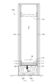
- FIG. 1 is a front view of a meshing chain type vertical conveyor according to an embodiment of the present invention
- FIG. 2 is a side view of the meshing chain type vertical conveyor shown in FIG. 1
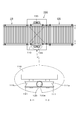
- FIG. 4 is a plan view of the meshing chain type vertical conveyance machine shown in FIG. 1
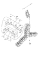
- FIG. 4 is a perspective view showing a disassembled and assembled state of the meshing chain, and a disengaged state
- FIG. 5 is a perspective view of the vicinity of the drive sprocket.
- FIG. 6 is a schematic view showing a state where the meshing chain is disengaged
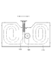
- FIG. 7 is a diagram showing a state where the guide roller is clamped with respect to the guide pole.
- An interlocking chain type vertical conveyor 100 is used for manufacturing equipment in various manufacturing fields, transport equipment in the transport field, and the like, as shown in FIGS.
- a workpiece W such as a heavy object carried from the carry-in side roll conveyor IR is mounted on the lifting table 110, the lifting table 110 is lifted and lowered vertically with respect to the installation surface of the work area, and the workpiece mounted on the lifting table 110. W is carried out to the carry-out side roll conveyor OR at the upper position.
- the lifting table 110 when lowered is indicated by a solid line, and the lifting table 110 when lifted is indicated by a virtual line.
- or FIG. 3 shows the conveyance direction of the workpiece
- the meshing chain type vertical transfer machine 100 includes a lifting table 110 having a rectangular mounting surface on which the workpiece W described above is mounted, and a bottom center of the lifting table 110.
- a pair of front and rear meshing chains 120 that support the portion to drive the lifting table 110 to be movable up and down, a pair of front and rear guide poles 130 that guide and guide both side surfaces of the lifting table 110, and a pair of meshing chains 120.
- a drive sprocket 140 that can be moved up and down is provided, and a drive motor 150 that supplies a drive force to the drive sprocket 140.
- both side surfaces of the lifting table 110 that is lifted and lowered by the pair of meshing chains 120 are guided and guided by the pair of guide poles 130, respectively, and the pair of meshing chains 120, the drive sprocket 140, A drive motor 150 can be installed.
- the pair of meshing chains 120 described above includes an inner link unit 123 formed by press-fitting a pair of front and rear bushes 122 to hook-like inner teeth plates 121 spaced apart from each other on the left and right sides.
- a large number of connecting pins 125 in the longitudinal direction of the chain are connected by a pair of connecting pins 125 that are press-fitted into a pair of front and rear pin holes of the hook-shaped external tooth plate 124 arranged on the outermost side in the width direction.
- the pair of meshing chains 120 are lifted in a self-supporting state by meshing the hook-like inner tooth plates 121 and the hook-like outer tooth plates 124 facing each other while deflecting from the horizontal direction to the vertical direction.
- the hook-like inner tooth plates 121 and the hook-like outer tooth plates 124 are disengaged and branched while being deflected from the vertical direction to the horizontal direction.
- the pair of meshing chains 120 described above are configured to be rigidly integrated with each other in a state of being opposed to each other and arranged so as to be disengaged from each other and freely branched.
- the uppermost lifting position of the lifting table 110 is set up to a rising position where the pair of meshing chains 120 are rigidized together. The lowest position of the lifting table 110 can be set.
- reference numeral 160 shown in FIG. 5 is a chain guide plate that is provided in the crotch region at the deflection position of the pair of meshing chains 120 and guides and moves the pair of meshing chains 120.
- the meshing chains 120 are meshed with each other and raised in a self-supporting state, and the pair of meshing chains 120 are separated from each other and branched.
- Reference numeral 170 shown in FIG. 5 to FIG. 6 denotes a chain storage means including a take-up type chain storage box for storing each of the meshing chains branched by the pair of meshing chains 120 being disengaged from each other. Similar to the drive motor 160, the means 170 is spaced apart from the area around the lowest position of the lifting table 110, that is, under the projection umbrella of the lifting table 110. Further, reference numeral 180 shown in FIGS.
- 1 to 2 denotes a so-called equipment room and the above-described lifting table 110 in which the above-described drive motor 150, chain guide plate 160, chain storage means 170, and the like are collectively arranged, so-called This is a separate plate that separates the transfer chamber, and the separate plate 180 further improves the maintainability.
- the drive sprocket 140 described above is provided at a rigid position where a pair of meshing chains 120 are integrally meshed as shown in FIGS.
- the drive sprocket 140 meshes with a pair of stiffened meshing chains 120 to form a so-called pinion rack mechanism, so that the meshing chain 120 is driven at a deflection position that is deflected from the chain branching direction to the chain meshing direction.
- Generation of a well-known chordal action (polygonal motion) that occurs between the drive sprocket 140 and the meshing chain 120 when wound around the sprocket 140 is avoided, and vertical motion (pulsation), vibration, and noise caused by this chordal action are avoided. This prevents the occurrence of speed fluctuations and realizes stable up / down driving of the workpiece.
- the drive sprocket 140 described above is provided on one of the pair of meshing chains 120 as shown in FIGS. This reduces the number of parts of the entire device, simplifies the device configuration, and designs and devices for other components as compared to the mesh chain type vertical conveyor that installs drive sprockets on both of the pair of mesh chains 120 respectively. In addition to ensuring a high degree of freedom with respect to the overall installation location, etc., the work burden associated with device assembly and maintenance is further reduced.
- the drive motor 150 described above employs a servo motor. As a result, the rotational speed of the servo motor can be easily controlled, so that the lifting range and stop position of the lifting table 110 are freely and accurately controlled.
- the pair of meshing chains 120, the drive sprocket 140, and the drive motor 150 are disposed in the vertical projection plane of the lifting table 110. 120, the drive sprocket 140, and the drive motor 150 are installed, and space saving of the installation surface is realized.
- a guide roller 111 composed of a total of four left and right drum rollers that roll along the guide pole 130 while sandwiching the guide pole 130 composed of a cylindrical body, It is arrange
- the arc-shaped curved roller surface 111a of the guide roller 111 smoothly rolls along the guide pole 130 in a state where the arc-shaped curved roller surface 111a is engaged with the circumferential surface 130a of the guide pole 130 so as to be sandwiched.
- the guide roller 111 described above is mounted in an L-shaped hole 111b provided in a bracket for assembling the guide rollers 111 together, as shown in FIG. Thus, the guide pole 130 is securely clamped.
- the clamping direction X of the pair of guide rollers 111 facing the above-described guide pole 130 is relative to the meshing direction Y in which the pair of meshing chains 120 are meshed with each other.
- one of the left and right and front and rear rolls, which tend to occur in the lifting table 110 in a sandwiched state between the circumferential surface 130a of the guide pole 130 and the arcuate curved roller surface 111a of the guide roller 111 is prevented, and a pair of meshing
- the other side-to-side front / rear side roll that tends to occur in the lifting table 110 due to the engagement of the chain 120 is prevented.
- the clamping direction X of the pair of guide rollers 111 is orthogonal to the meshing direction Y of the pair of meshing chains 120. Even if it is tilted with respect to the meshing direction Y of the meshing chain 120, it is possible to prevent the other side-to-side back and forth rolls.
- the conveying operation of the meshing chain type vertical conveying machine 100 will be described below with reference to FIGS.
- the work W carried from the carry-in side roll conveyor IR at the lower position of the work area is mounted on the lifting table 110, and the lifting table 110 is lifted by the pair of meshing chains 120 while being guided and guided upward by the guide pole 130.
- the workpiece W mounted on the lifting table 110 is carried out to the carry-out side roll conveyor OR at the upper position.
- the lift table 110 after the work W is carried out to the carry-out side roll conveyor OR at the upper position is lowered to the lower position of the work area by the pair of meshing chains 120 while being guided and guided downward by the guide pole 130, and carried in. It waits for the work W carried in from the side roll conveyor IR.
- the meshing chain type vertical conveyance machine 100 of the present embodiment is configured to sequentially convey the workpiece W vertically by raising and lowering the elevating table 110 by repeating the above-described operation.
- the meshing chain type vertical conveyor 100 of the present embodiment obtained in this way includes a pair of meshing chains 120 that supports the center of the bottom surface of the lifting table 110 on which the workpiece W is mounted and is driven to move up and down, and the lifting table.
- the lift table 110 is provided with a pair of guide poles 130 for guiding and guiding both side surfaces of the 110 and a drive motor 150 for supplying a drive force to the drive sprocket 140 for driving the pair of meshing chains 110 to be movable up and down.
- a pair of guide rollers 111 that roll along the guide pole 130 with the guide pole 130 sandwiched are disposed on both side surfaces of the lifting table 110 and the pair of guide rollers 111 facing the guide pole 130 are sandwiched. Since the direction X is orthogonal to the meshing direction Y in which the pair of meshing chains 120 are meshed with each other, it is possible to completely and reliably prevent the lateral shaking that is likely to occur in the lifting table 110. The effect is enormous.
Landscapes
- Engineering & Computer Science (AREA)
- Mechanical Engineering (AREA)
- General Engineering & Computer Science (AREA)
- Life Sciences & Earth Sciences (AREA)
- Geology (AREA)
- Structural Engineering (AREA)
- Intermediate Stations On Conveyors (AREA)
- Chain Conveyers (AREA)
Abstract
昇降テーブル(110)を昇降自在に駆動する一対の噛合チェーン(120)と、昇降テーブル(110)の両側面を誘導案内する一対のガイドポール(130)と、一対の噛合チェーン(120)を駆動する駆動スプロケットに駆動力を供給する駆動モータ(150)とを備え、一対の噛合チェーン(120)が相互に噛み合って対向配置した状態で一体に剛直化するとともに相互に噛み外れて分岐自在となるように構成され、ガイドポール(130)を挟持した状態でガイドポール(130)に沿って転動する一対のガイドローラ(111)が昇降テーブル(110)の両側面に配置されている噛合チェーン式垂直搬送機(100)。
Description
本発明は、各種製造分野の製造設備、運輸分野の移送設備などに用いてワークを昇降させる垂直搬送機であって、特に、噛合チェーンを昇降動作の駆動媒体として採用した噛合チェーン式垂直搬送機に関する。
従来、垂直搬送機として、下階から上階まで貫通して設けたフレームの内部に箱型のキャリッジが条体により保持され、モータにより駆動してキャリッジを昇降させるものがある(例えば、特許文献1参照。)。
ところが、このような垂直搬送機は、キャリッジをワイヤーチェーンなどの条体で吊り下げてモータにより昇降駆動させているため、ワイヤーチェーンなどの条体が過度に伸びる可能性があり、モータの回転数を制御してもキャリッジの停止位置がずれて搬送作業に支障を来すという問題があった。
そして、キャリッジをワイヤーチェーンなどの条体で吊り下げて昇降駆動させるため、条体が装置フレーム内で複雑に取り回されており、日常時における昇降領域の清掃作業や長期使用した条体の交換作業が煩雑になるという問題があるとともに、搬送スペースの他にワイヤーチェーンなどの条体を取り回すスペースなどが必要となり、装置全体の大型化を回避できないという問題があった。
また、キャリッジをワイヤーチェーンなどの条体で吊り下げて昇降駆動させるため、チェーン潤滑油が搬送時の振動により飛散し、ワークを汚染することがあり、このようなワークの汚染を防止するために汚染防止用カバーなどを付設すると、設置スペースが拡大するばかりでなく、汚染防止用カバーの重量分だけ搬送負荷が増大するという問題があった。
さらに、キャリッジをワイヤーチェーンなどの条体で吊り下げて昇降駆動させるため、チェーンの噛み外れがワイヤーチェーンなどの条体に対して横揺れと縦揺れを惹起させて、昇降搬送時に搭載したワークが不安定になるという問題があった。
そこで、本発明は、従来の問題を解決するものであって、すなわち、本発明の目的は、昇降テーブルの横揺れと縦揺れを防止して確実かつ安定したワークの垂直搬送と省スペース化を実現するとともに、昇降領域の清掃作業や昇降部品の交換作業などの簡便な保守メンテナンス作業を実現する噛合チェーン式垂直搬送機を提供することである。
請求項1に係る本発明は、ワークを搭載する昇降テーブルと該昇降テーブルの底面中央部を支持して昇降テーブルを昇降自在に駆動する一対の噛合チェーンと前記昇降テーブルの両側面を誘導案内する一対のガイドポールと前記一対の噛合チェーンを昇降自在に駆動する駆動スプロケットと該駆動スプロケットに駆動力を供給する駆動モータとを備えた噛合チェーン式垂直搬送機であって、前記一対の噛合チェーンが相互に噛み合って対向配置した状態で一体に剛直化するとともに相互に噛み外れて分岐自在となるように構成され、前記ガイドポールを挟持した状態でガイドポールに沿って転動するガイドローラが前記昇降テーブルの両側面に配置されていることにより、前述した課題を解決したものである。
請求項2に係る本発明は、請求項1に記載の構成に加えて、前記ガイドポールに対向する一対のガイドローラの挟持方向が、前記一対の噛合チェーンを相互に噛み合わせた噛合方向に対して直交または傾交していることにより、前述した課題を解決したものである。
請求項3に係る本発明は、請求項1または請求項2に記載の構成に加えて、前記ガイドポールが円柱体から構成されているとともに、前記ガイドローラが鼓型ローラから構成されていることにより、前述した課題を解決したものである。
請求項4に係る本発明は、請求項1乃至請求項3のいずれかに記載の構成に加えて、前記駆動スプロケットが、前記一対の噛合チェーンを一体に噛み合せた剛直位置に設けられていることにより、前述した課題を解決したものである。
請求項5に係る本発明は、請求項1乃至請求項4のいずれかに記載の構成に加えて、前記駆動スプロケットが、前記一対の噛合チェーンの一方に設けられていることにより、前述した課題を解決したものである。
請求項6に係る本発明は、請求項1乃至請求項5のいずれかに記載の構成に加えて、前記駆動モータが、サーボモータであることにより、前述した課題を解決したものである。
請求項7に係る本発明は、請求項1乃至請求項6のいずれかに記載の構成に加えて、前記一対の噛合チェーンと駆動スプロケットと駆動モータが、前記昇降テーブルの垂直投影面内に配置されていることにより、前述した課題を解決したものである。
請求項1に係る本発明の噛合チェーン式垂直搬送機によれば、ワークを搭載する昇降テーブルとこの昇降テーブルの底面中央部を支持して昇降テーブルを昇降自在に駆動する一対の噛合チェーンと前記昇降テーブルの両側面を誘導案内する一対のガイドポールと前記一対の噛合チェーンを昇降自在に駆動する駆動スプロケットとこの駆動スプロケットに駆動力を供給する駆動モータとを備えていることによって、一対の噛合チェーンで昇降する昇降テーブルの両側面が一対のガイドポールでそれぞれ誘導案内されるため、昇降テーブルに生じがちな横揺れと縦揺れを防止して確実かつ安定したワークの垂直搬送を実現し、また、昇降テーブルの底面下部領域内に一対の噛合チェーンや駆動スプロケットや駆動モータを設置することが可能になるため、昇降テーブルの上面領域内における清掃作業や昇降テーブルの底面下部領域内における昇降部品の交換作業などの簡便な保守メンテナンス作業を実現することができる。
そして、一対の噛合チェーンが相互に噛み合って対向配置した状態で一体に剛直化するとともに相互に噛み外れて分岐自在となるように構成されていることにより、一対の噛合チェーンが相互に噛み合って対向配置した状態で一体に剛直化する上昇位置まで昇降テーブルの最上昇位置を設定するとともに一対の噛合チェーンが相互に噛み外れて分岐する直前位置まで昇降テーブルの最下降位置を設定することが可能になるため、昇降テーブルの
昇降ストロークを最大限に発揮することができる。
昇降ストロークを最大限に発揮することができる。
また、ガイドポールを挟持した状態でガイドポールに沿って転動するガイドローラが昇降テーブルの両側面に配置されていることにより、ガイドローラがガイドポールに挟持状態でガイドポールに沿って転動走行するため、昇降テーブルの横揺れを抑制して昇降テーブルを円滑に昇降させることができる。
そして、請求項2に係る噛合チェーン式垂直搬送機によれば、請求項1に記載の噛合チェーン式垂直搬送機が奏する効果に加えて、ガイドポールに対向する一対のガイドローラの挟持方向が一対の噛合チェーンを相互に噛み合わせた噛合方向に対して直交または傾交していることにより、ガイドポールとガイドローラとの挟持状態で昇降テーブルに生じがちな左右前後のいずれか一方の横揺れを防止し、一対の噛合チェーンの噛み合わせで昇降テーブルに生じがちな左右前後の他方の横揺れを防止するため、昇降テーブルに生じがちな左右前後の横揺れを完全かつ確実に防止することができる。
また、請求項3に係る噛合チェーン式垂直搬送機によれば、請求項1または請求項2に記載の噛合チェーン式垂直搬送機が奏する効果に加えて、ガイドポールが円柱体から構成されているとともに、ガイドローラが鼓型ローラから構成されていることにより、ガイドローラの円弧状湾曲ローラ面がガイドポールの円周面に凹凸係合して挟持状態でガイドポールに沿って円滑に転動走行するため、昇降テーブルの横揺れを確実に防止することができる。
また、請求項4に係る噛合チェーン式垂直搬送機によれば、請求項1乃至請求項3の何れか1つに記載の噛合チェーン式垂直搬送機が奏する効果に加えて、駆動スプロケットが一対の噛合チェーンを一体に噛み合せた剛直位置に設けられていることにより、剛直化した一対の噛合チェーンに対して駆動スプロケットが噛み合って、所謂、ピニオンラック機構を呈するため、チェーン分岐方向からチェーン噛合方向へ偏向駆動される偏向位置で噛合チェーンを駆動スプロケットに巻き掛けた場合に駆動スプロケットと噛合チェーンとの間で生じる周知のコーダルアクション(多角形運動)の発生が回避され、このコーダルアクションに起因した上下動(脈動)、振動、騒音、速度変動の発生を防止でき、ワークの安定した昇降駆動を実現することができる。
請求項5に係る噛合チェーン式垂直搬送機によれば、請求項1乃至請求項4のいずれか1つに記載の噛合チェーン式垂直搬送機が奏する効果に加えて、駆動スプロケットが一対の噛合チェーンの一方に設けられていることにより、一対の噛合チェーンの両方に昇降用スプロケットをそれぞれ設置する噛合チェーン式垂直搬送機と比較して装置全体の部品点数が低減するため、装置構成を簡素化して他構成部材の設計や装置全体の設置場所等に関する高い自由度を確保できるとともに、装置組立および保守メンテナンスに係る作業負担をより低減することができる。
また、一対の噛合チェーンの両方に駆動スプロケットをそれぞれ設置した噛合チェーン式垂直搬送機において生じがちな一対の駆動スプロケット間の回転位相ズレに起因した一対の噛合チェーン間の噛合振動の発生を回避するため、ワークの安定した昇降動作を実現することができる。
そして、請求項6に係る噛合チェーン式垂直搬送機によれば、請求項1乃至請求項5のいずれか1つに記載の噛合チェーン式垂直搬送機が奏する効果に加えて、駆動モータがサーボモータであることにより、サーボモータの回転数が簡便に制御可能となるため、昇降テーブルの昇降範囲や停止位置を自由かつ正確に制御することができる。
さらに、請求項7に係る噛合チェーン式垂直搬送機によれば、請求項1乃至請求項6のいずれか1つに記載の噛合チェーン式垂直搬送機が奏する効果に加えて、一対の噛合チェーンと駆動スプロケットと駆動モータが昇降テーブルの垂直投影面内に配置されていることにより、昇降テーブルの底面下部領域内に一対の噛合チェーンや駆動スプロケットや駆動モータを設置することが可能になるため、省スペース化を実現することができる。
本発明の噛合チェーン式垂直搬送機は、ワークを搭載する昇降テーブルとこの昇降テーブルの底面中央部を支持して昇降テーブルを昇降自在に駆動する一対の噛合チェーンと前記昇降テーブルの両側面を誘導案内する一対のガイドポールと前記一対の噛合チェーンを昇降自在に駆動する駆動スプロケットとこの駆動スプロケットに駆動力を供給する駆動モータとを備え、一対の噛合チェーンが相互に噛み合って対向配置した状態で一体に剛直化するとともに相互に噛み外れて分岐自在となるように構成され、ガイドポールを挟持した状態でガイドポールに沿って転動するガイドローラが昇降テーブルの両側面に配置され、昇降テーブルの横揺れと縦揺れを防止して確実かつ安定したワークの垂直搬送と省スペース化を実現し、昇降領域の清掃作業や昇降部品の交換作業などの簡便な保守メンテナンス作業を実現するものであれば、その具体的な実施の態様は、如何なるものであっても何ら構わない。
たとえば、本発明の噛合チェーン式垂直搬送機は、ワークを搭載する昇降テーブルを下部位置と上部位置との間で垂直搬送することが可能であれば、如何なる装置レイアウトであっても良く、例えば、下部位置に連接した搬入側コンベヤなどのワーク搬入側から搬入したワークを上昇させて垂直搬送した後に、下部位置側の上部位置あるいは下部位置と反対側の上部位置に連接した搬出側コンベヤなどのワーク搬出側へ搬出するもの、もしくは、その逆にワークを下降させて垂直搬送するものなどのいずれであっても適用することができる。
そして、本発明の噛合チェーン式垂直搬送機で用いられる一対の噛合チェーンは、一対の駆動スプロケットにより相互に噛み合わせて一体化するとともに一対の駆動スプロケットにより相互に噛み外れて分岐するものであれば、その具体的なチェーン形態は如何なるものであっても良く、例えば、チェーン幅方向に1列の単列であるもの、チェーン幅方向に2列以上の複列であるものなど何れであっても構わないが、チェーン幅方向に2列以上の複列であるものを採用する場合には、一対の噛合チェーンの一方を構成するフック状外歯プレートとフック状内歯プレートが、これに対向する他方の噛合チェーンを構成するフック状外歯プレートとフック状内歯プレートに対してチェーン幅方向の複列に亙ってそれぞれフック状に多重かつ強固に噛み合うため、噛合チェーンのチェーン幅方向に生じがちな座屈を確実に抑制して優れたチェーン耐久性を実現できるので、より好ましい。
また、本発明の噛合チェーン式垂直搬送機で用いられる一対の噛合チェーンは、ローラを有していないもの、すなわち、ブシュのみを有するもの、ローラを有するものなど何れであっても構わないが、ブシュのみを有するものを採用する場合には、チェーン部品点数が低減して、チェーン重量の軽量化を図ることができる。
そして、本発明の噛合チェーン式垂直搬送機で用いられるガイドポールは、ガイドローラがガイドポールに沿って転動するものであれば、円周面を有する円柱体、若しくは、三角形や矩形の周面を有する角柱体のいずれであっても良い。
他方、本発明の噛合チェーン式垂直搬送機で用いられるガイドローラは、通常のローラ軸方向に平坦なローラ面を有する円柱型ローラ、若しくは、円弧状湾曲ローラ面を有する鼓型ローラのいずれであっても良い。
そして、このようなガイドローラに配置形態については、ガイドポールを挟持した状態でガイドポールに沿って転動して昇降テーブルの横揺れを防止する配置形態であれば良く、例えば、ガイドポールに対して2個または4個で挟持した配置形態でも良いが、4個で挟持した配置形態の場合にはガイドポールに沿って安定して転動することができる。
また、ガイドポールを挟持した状態でガイドポールに沿って転動して昇降テーブルの横揺れを防止する配置形態であれば、3個からなる奇数配置であっても何ら構わない。
他方、本発明の噛合チェーン式垂直搬送機で用いられるガイドローラは、通常のローラ軸方向に平坦なローラ面を有する円柱型ローラ、若しくは、円弧状湾曲ローラ面を有する鼓型ローラのいずれであっても良い。
そして、このようなガイドローラに配置形態については、ガイドポールを挟持した状態でガイドポールに沿って転動して昇降テーブルの横揺れを防止する配置形態であれば良く、例えば、ガイドポールに対して2個または4個で挟持した配置形態でも良いが、4個で挟持した配置形態の場合にはガイドポールに沿って安定して転動することができる。
また、ガイドポールを挟持した状態でガイドポールに沿って転動して昇降テーブルの横揺れを防止する配置形態であれば、3個からなる奇数配置であっても何ら構わない。
さらに、本発明の噛合チェーン式垂直搬送機で用いられる昇降テーブルの具体的な形態については、搬入側コンベヤや搬出側コンベヤとの乗り継ぎ時に支障が少ない矩形の搭載面を備えたものが好ましく、また、そのワークを搭載する搭載面にロールコンベヤが付設されている場合は、昇降テーブルに対するワークの搬入搬出作業を簡便に達成することができる。
以下、本発明の一実施例である噛合チェーン式垂直搬送機100を図面に基づいて説明する。
ここで、図1は、本発明の一実施例である噛合チェーン式垂直搬送機の正面図であり、図2は、図1に示す噛合チェーン式垂直搬送機の側面図であり、図3は、図1に示す噛合チェーン式垂直搬送機の平面図であり、図4は、噛合チェーンの分解組み立て状態と噛み外れ状態を示す斜視図であり、図5は、駆動スプロケット近傍の斜視図であり、図6は、噛合チェーンの噛み外れ状態の概略図であり、図7は、ガイドポールに対するガイドローラの挟持状態を示す図である。
ここで、図1は、本発明の一実施例である噛合チェーン式垂直搬送機の正面図であり、図2は、図1に示す噛合チェーン式垂直搬送機の側面図であり、図3は、図1に示す噛合チェーン式垂直搬送機の平面図であり、図4は、噛合チェーンの分解組み立て状態と噛み外れ状態を示す斜視図であり、図5は、駆動スプロケット近傍の斜視図であり、図6は、噛合チェーンの噛み外れ状態の概略図であり、図7は、ガイドポールに対するガイドローラの挟持状態を示す図である。
本発明の一実施例である噛合チェーン式垂直搬送機100は、各種製造分野の製造設備、運輸分野の移送設備などに用いるものであって、図1乃至図3に示すように、下部位置の搬入側ロールコンベヤIRから搬入された重量物などのワークWを昇降テーブル110に搭載し、この昇降テーブル110を作業エリアの設置面に対して昇降させて垂直搬送し、昇降テーブル110に搭載したワークWを上部位置の搬出側ロールコンベヤORへ搬出させるものである。
なお、図1乃至図3には、下降時の昇降テーブル110を実線で示し、上昇時の昇降テーブル110を仮想線で示す。また、図1乃至図3の太い矢印は、本実施例におけるワークWの搬送方向を示す。
なお、図1乃至図3には、下降時の昇降テーブル110を実線で示し、上昇時の昇降テーブル110を仮想線で示す。また、図1乃至図3の太い矢印は、本実施例におけるワークWの搬送方向を示す。
そして、本実施例の噛合チェーン式垂直搬送機100は、図1乃至図3に示すように、前述したワークWを搭載する矩形の搭載面を有する昇降テーブル110と、この昇降テーブル110の底面中央部を支持して昇降テーブル110を昇降自在に駆動する前後一対の噛合チェーン120と、昇降テーブル110の両側面を誘導案内する前後一対の円柱体からなるガイドポール130と、一対の噛合チェーン120を昇降自在に駆動する駆動スプロケット140と、この駆動スプロケット140に駆動力を供給する駆動モータ150とを備えている。
これにより、一対の噛合チェーン120で昇降する昇降テーブル110の両側面が一対のガイドポール130でそれぞれ誘導案内されるとともに、昇降テーブル110の底面下部領域内に一対の噛合チェーン120や駆動スプロケット140や駆動モータ150を設置することが可能になっている。
これにより、一対の噛合チェーン120で昇降する昇降テーブル110の両側面が一対のガイドポール130でそれぞれ誘導案内されるとともに、昇降テーブル110の底面下部領域内に一対の噛合チェーン120や駆動スプロケット140や駆動モータ150を設置することが可能になっている。
そして、前述した一対の噛合チェーン120は、図4に示すように、左右一対で離間配置されるフック状内歯プレート121に前後一対のブシュ122を圧入嵌合してなる内リンクユニット123がチェーン幅方向の最も外側に配置されたフック状外歯プレート124の前後一対のピン孔に圧入嵌合する前後一対の連結ピン125によりチェーン長手方向に多数連結されている。
このようにして、一対の噛合チェーン120は、水平方向から垂直方向へ偏向しながら相互に対向するフック状内歯プレート121同士およびフック状外歯プレート124同士をそれぞれ噛み合せて一体に自立状態で上昇するようになっており、また、垂直方向から水平方向へ偏向しながらフック状内歯プレート121同士およびフック状外歯プレート124同士をそれぞれ噛み外して分岐するようになっている。
このようにして、一対の噛合チェーン120は、水平方向から垂直方向へ偏向しながら相互に対向するフック状内歯プレート121同士およびフック状外歯プレート124同士をそれぞれ噛み合せて一体に自立状態で上昇するようになっており、また、垂直方向から水平方向へ偏向しながらフック状内歯プレート121同士およびフック状外歯プレート124同士をそれぞれ噛み外して分岐するようになっている。
したがって、前述した一対の噛合チェーン120は、図6に示すように、相互に噛み合って対向配置した状態で一体に剛直化するとともに相互に噛み外れて分岐自在となるように構成されているため、一対の噛合チェーン120が相互に噛み合って対向配置した状態で一体に剛直化する上昇位置まで昇降テーブル110の最上昇位置を設定するとともに一対の噛合チェーン120が相互に噛み外れて分岐する直前位置まで昇降テーブル110の最下降位置を設定することが可能になっている。
なお、図5に示す符号160は、一対の噛合チェーン120の偏向位置の股間領域に設けて一対の噛合チェーン120を誘導移動するチェーン誘導プレートであり、このチェーン誘導プレート160が、上昇駆動時に一対の噛合チェーン120を相互に噛み合わせて一体に自立状態で上昇させるとともに、一対の噛合チェーン120を相互に噛み外して分岐させるようになっている。
また、図5乃至図6に示す符号170は、一対の噛合チェーン120が相互に噛み外れて分岐した噛合チェーンをそれぞれ収納する巻き取り型のチェーン収納ボックスからなるチェーン収納手段であり、このチェーン収納手段170は、駆動モータ160と同様に、昇降テーブル110の最下降位置の周辺域、すなわち、昇降テーブル110の投影傘下に離間配置されている。
さらに、図1乃至図2に示す符号180は、前述した駆動モータ150、チェーン誘導プレート160、チェーン収納手段170などを集合配置した、いわゆる、機器室と前述した昇降テーブル110を昇降させる、いわゆる、搬送室とを仕切るセパレート板であり、このセパレート板180により、メンテナンス性をさらに向上させている。
さらに、図1乃至図2に示す符号180は、前述した駆動モータ150、チェーン誘導プレート160、チェーン収納手段170などを集合配置した、いわゆる、機器室と前述した昇降テーブル110を昇降させる、いわゆる、搬送室とを仕切るセパレート板であり、このセパレート板180により、メンテナンス性をさらに向上させている。
そして、前述した駆動スプロケット140は、図5乃至図6に示すように、一対の噛合チェーン120を一体に噛み合せた剛直位置に設けられている。
これにより、剛直化した一対の噛合チェーン120に対して駆動スプロケット140が噛み合って、所謂、ピニオンラック機構を呈するため、チェーン分岐方向からチェーン噛合方向へ偏向駆動される偏向位置で噛合チェーン120を駆動スプロケット140に巻き掛けた場合に駆動スプロケット140と噛合チェーン120との間で生じる周知のコーダルアクション(多角形運動)の発生が回避され、このコーダルアクションに起因した上下動(脈動)、振動、騒音、速度変動の発生を防止し、ワークの安定した昇降駆動を実現している。
これにより、剛直化した一対の噛合チェーン120に対して駆動スプロケット140が噛み合って、所謂、ピニオンラック機構を呈するため、チェーン分岐方向からチェーン噛合方向へ偏向駆動される偏向位置で噛合チェーン120を駆動スプロケット140に巻き掛けた場合に駆動スプロケット140と噛合チェーン120との間で生じる周知のコーダルアクション(多角形運動)の発生が回避され、このコーダルアクションに起因した上下動(脈動)、振動、騒音、速度変動の発生を防止し、ワークの安定した昇降駆動を実現している。
さらに、前述した駆動スプロケット140は、図5乃至図6に示すように、一対の噛合チェーン120の一方に設けられている。
これにより、一対の噛合チェーン120の両方に駆動スプロケットをそれぞれ設置する噛合チェーン式垂直搬送機と比較して、装置全体の部品点数を低減し、装置構成を簡素化して他構成部材の設計や装置全体の設置場所等に関する高い自由度を確保するとともに、装置組立および保守メンテナンスに係る作業負担をより低減している。
これにより、一対の噛合チェーン120の両方に駆動スプロケットをそれぞれ設置する噛合チェーン式垂直搬送機と比較して、装置全体の部品点数を低減し、装置構成を簡素化して他構成部材の設計や装置全体の設置場所等に関する高い自由度を確保するとともに、装置組立および保守メンテナンスに係る作業負担をより低減している。
また、前述した駆動モータ150には、サーボモータを採用している。
これにより、サーボモータの回転数が簡便に制御可能となるため、昇降テーブル110の昇降範囲や停止位置が自由かつ正確に制御されるようになっている。
これにより、サーボモータの回転数が簡便に制御可能となるため、昇降テーブル110の昇降範囲や停止位置が自由かつ正確に制御されるようになっている。
そして、上述したように、一対の噛合チェーン120と駆動スプロケット140と駆動モータ150とは、昇降テーブル110の垂直投影面内に配置されるため、昇降テーブル110の底面下部領域内に一対の噛合チェーン120や駆動スプロケット140や駆動モータ150を設置することになり、設置面の省スペース化を実現している。
つぎに、本実施例の噛合チェーン式垂直搬送機100が最も特徴とする昇降テーブル110と噛合チェーン120とガイドポール130との相互の配置形態について、以下に説明する。
まず、図1および図7に示すように、円柱体からなるガイドポール130を挟持した状態でガイドポール130に沿って転動する左右一対の計4個の鼓型ローラからなるガイドローラ111が、昇降テーブル110の両側面にそれぞれ配置されている。
これにより、ガイドローラ111の円弧状湾曲ローラ面111aが、ガイドポール130の円周面130aに凹凸係合して挟持した状態でガイドポール130に沿って円滑に転動走行するようになっている。
なお、前述したガイドローラ111は、図7に示すように、ガイドローラ111同士を一体に組みつけるためのブラケットに設けたL字状穴111bに装着されており、ガイドポール130に対するズレなどを抑制してガイドポール130を確実に挟持するようになっている。
まず、図1および図7に示すように、円柱体からなるガイドポール130を挟持した状態でガイドポール130に沿って転動する左右一対の計4個の鼓型ローラからなるガイドローラ111が、昇降テーブル110の両側面にそれぞれ配置されている。
これにより、ガイドローラ111の円弧状湾曲ローラ面111aが、ガイドポール130の円周面130aに凹凸係合して挟持した状態でガイドポール130に沿って円滑に転動走行するようになっている。
なお、前述したガイドローラ111は、図7に示すように、ガイドローラ111同士を一体に組みつけるためのブラケットに設けたL字状穴111bに装着されており、ガイドポール130に対するズレなどを抑制してガイドポール130を確実に挟持するようになっている。
そして、本実施例の噛合チェーン式垂直搬送機100では、前述したガイドポール130に対向する一対のガイドローラ111の挟持方向Xが、一対の噛合チェーン120を相互に噛み合わせた噛合方向Yに対して直交している。
これにより、ガイドポール130の円周面130aとガイドローラ111の円弧状湾曲ローラ面111aとの挟持状態で昇降テーブル110に生じがちな左右前後のいずれか一方の横揺れを防止し、一対の噛合チェーン120の噛み合わせで昇降テーブル110に生じがちな左右前後の他方の横揺れを防止している。
なお、本実施例の噛合チェーン式垂直搬送機100では、前述したように、一対のガイドローラ111の挟持方向Xが、一対の噛合チェーン120の噛合方向Yに対して直交しているが、一対の噛合チェーン120の噛合方向Yに対して傾交していても、同様に左右前後の他方の横揺れを防止することが可能である。
これにより、ガイドポール130の円周面130aとガイドローラ111の円弧状湾曲ローラ面111aとの挟持状態で昇降テーブル110に生じがちな左右前後のいずれか一方の横揺れを防止し、一対の噛合チェーン120の噛み合わせで昇降テーブル110に生じがちな左右前後の他方の横揺れを防止している。
なお、本実施例の噛合チェーン式垂直搬送機100では、前述したように、一対のガイドローラ111の挟持方向Xが、一対の噛合チェーン120の噛合方向Yに対して直交しているが、一対の噛合チェーン120の噛合方向Yに対して傾交していても、同様に左右前後の他方の横揺れを防止することが可能である。
そこで、本実施例の噛合チェーン式垂直搬送機100の搬送動作について、図1乃至図3に基づいて、以下に説明する。
まず、作業エリアの下部位置の搬入側ロールコンベヤIRから搬入されたワークWを昇降テーブル110に搭載し、この昇降テーブル110をガイドポール130で上方へ誘導案内しながら一対の噛合チェーン120により上昇させて垂直搬送した後、昇降テーブル110に搭載したワークWを上部位置の搬出側ロールコンベヤORへ搬出させる。
まず、作業エリアの下部位置の搬入側ロールコンベヤIRから搬入されたワークWを昇降テーブル110に搭載し、この昇降テーブル110をガイドポール130で上方へ誘導案内しながら一対の噛合チェーン120により上昇させて垂直搬送した後、昇降テーブル110に搭載したワークWを上部位置の搬出側ロールコンベヤORへ搬出させる。
次いで、ワークWを上部位置の搬出側ロールコンベヤORへ搬出させた後の昇降テーブル110は、ガイドポール130で下方へ誘導案内しながら一対の噛合チェーン120により作業エリアの下部位置まで下降させ、搬入側ロールコンベヤIRから搬入されるワークWを待ち受ける。
したがって、本実施例の噛合チェーン式垂直搬送機100は、上述したような動作を繰り返して昇降テーブル110を昇降させることにより、ワークWを順次垂直搬送するようになっている。
このようにして得られた本実施例の噛合チェーン式垂直搬送機100は、ワークWを搭載する昇降テーブル110の底面中央部を支持して昇降自在に駆動する一対の噛合チェーン120と、昇降テーブル110の両側面を誘導案内する一対のガイドポール130と、一対の噛合チェーン110を昇降自在に駆動する駆動スプロケット140に駆動力を供給する駆動モータ150などを備えていることにより、昇降テーブル110に生じがちな横揺れと縦揺れを防止して確実かつ安定したワークWの垂直搬送を実現し、昇降テーブル110の上面領域内における清掃作業や昇降テーブル110の底面下部領域内における昇降部品の交換作業などの簡便な保守メンテナンス作業を実現することができるとともに、昇降テーブル110の昇降ストロークを最大限に発揮することができる。
また、ガイドポール130を挟持した状態でガイドポール130に沿って転動する一対のガイドローラ111が昇降テーブル110の両側面に配置されているとともにガイドポール130に対向する一対のガイドローラ111の挟持方向Xが一対の噛合チェーン120を相互に噛み合わせた噛合方向Yに対して直交していることにより、昇降テーブル110に生じがちな左右前後の横揺れを完全かつ確実に防止することができるなど、その効果は甚大である。
100 ・・・ 噛合チェーン式垂直搬送機
110 ・・・ 昇降テーブル
111 ・・・ ガイドローラ
111a ・・・ 円弧状湾曲ローラ面
111b ・・・ L字状穴
120 ・・・ 一対の噛合チェーン
121 ・・・ フック状内歯プレート
122 ・・・ ブシュ
123 ・・・ 内リンクユニット
124 ・・・ フック状外歯プレート
125 ・・・ 連結ピン
130 ・・・ ガイドポール
130a ・・・ 円周面
140 ・・・ 駆動スプロケット
150 ・・・ 駆動モータ
160 ・・・ チェーン誘導プレート
170 ・・・ チェーン収納手段
180 ・・・ セパレート板
IR ・・・ 搬入側ロールコンベヤ
OR ・・・ 搬出側ロールコンベヤ
W ・・・ ワーク
X ・・・ 一対のガイドローラの挟持方向
Y ・・・ 一対の噛合チェーンの噛合方向
110 ・・・ 昇降テーブル
111 ・・・ ガイドローラ
111a ・・・ 円弧状湾曲ローラ面
111b ・・・ L字状穴
120 ・・・ 一対の噛合チェーン
121 ・・・ フック状内歯プレート
122 ・・・ ブシュ
123 ・・・ 内リンクユニット
124 ・・・ フック状外歯プレート
125 ・・・ 連結ピン
130 ・・・ ガイドポール
130a ・・・ 円周面
140 ・・・ 駆動スプロケット
150 ・・・ 駆動モータ
160 ・・・ チェーン誘導プレート
170 ・・・ チェーン収納手段
180 ・・・ セパレート板
IR ・・・ 搬入側ロールコンベヤ
OR ・・・ 搬出側ロールコンベヤ
W ・・・ ワーク
X ・・・ 一対のガイドローラの挟持方向
Y ・・・ 一対の噛合チェーンの噛合方向
Claims (7)
- ワークを搭載する昇降テーブルと該昇降テーブルの底面中央部を支持して昇降テーブルを昇降自在に駆動する一対の噛合チェーンと前記昇降テーブルの両側面を誘導案内する一対のガイドポールと前記一対の噛合チェーンを昇降自在に駆動する駆動スプロケットと該駆動スプロケットに駆動力を供給する駆動モータとを備えた噛合チェーン式垂直搬送機であって、
前記一対の噛合チェーンが相互に噛み合って対向配置した状態で一体に剛直化するとともに相互に噛み外れて分岐自在となるように構成され、
前記ガイドポールを挟持した状態でガイドポールに沿って転動するガイドローラが前記昇降テーブルの両側面に配置されていることを特徴とする噛合チェーン式垂直搬送機。 - 前記ガイドポールに対向する一対のガイドローラの挟持方向が、前記一対の噛合チェーンを相互に噛み合わせた噛合方向に対して直交または傾交していることを特徴とする請求項1記載の噛合チェーン式垂直搬送機。
- 前記ガイドポールが円柱体から構成されているとともに、前記ガイドローラが鼓型ローラから構成されていることを特徴とする請求項1または請求項2記載の噛合チェーン式垂直搬送機。
- 前記駆動スプロケットが、前記一対の噛合チェーンを一体に噛み合せた剛直位置に設けられていることを特徴とする請求項1乃至請求項3のいずれか1つに記載の噛合チェーン式垂直搬送機。
- 前記駆動スプロケットが、前記一対の噛合チェーンの一方に設けられていることを特徴とする請求項1乃至請求項4のいずれか1つに記載の噛合チェーン式垂直搬送機。
- 前記駆動モータが、サーボモータであることを特徴とする請求項1乃至請求項5のいずれか1つに記載の噛合チェーン式垂直搬送機。
- 前記一対の噛合チェーンと駆動スプロケットと駆動モータが、前記昇降テーブルの垂直投影面内に配置されていることを特徴とする請求項1乃至請求項6のいずれか1つに記載の噛合チェーン式垂直搬送機。
Applications Claiming Priority (2)
| Application Number | Priority Date | Filing Date | Title |
|---|---|---|---|
| JP2009-271606 | 2009-11-30 | ||
| JP2009271606A JP5133328B2 (ja) | 2009-11-30 | 2009-11-30 | 噛合チェーン式垂直搬送機 |
Publications (1)
| Publication Number | Publication Date |
|---|---|
| WO2011065141A1 true WO2011065141A1 (ja) | 2011-06-03 |
Family
ID=44066245
Family Applications (1)
| Application Number | Title | Priority Date | Filing Date |
|---|---|---|---|
| PCT/JP2010/068048 Ceased WO2011065141A1 (ja) | 2009-11-30 | 2010-10-14 | 噛合チェーン式垂直搬送機 |
Country Status (2)
| Country | Link |
|---|---|
| JP (1) | JP5133328B2 (ja) |
| WO (1) | WO2011065141A1 (ja) |
Cited By (7)
| Publication number | Priority date | Publication date | Assignee | Title |
|---|---|---|---|---|
| CN103287805A (zh) * | 2013-06-28 | 2013-09-11 | 苏州工业园区职业技术学院 | 料斗提升机 |
| WO2014139508A1 (de) * | 2013-03-15 | 2014-09-18 | Heinemack Gmbh | Restaurantsystem und verfahren zum betrieb eines restaurantsystems |
| US9237817B2 (en) | 2005-12-12 | 2016-01-19 | Heinemack Gmbh | Restaurant system |
| CN106516690A (zh) * | 2016-12-01 | 2017-03-22 | 无锡明珠钢球有限公司 | 一种零件托盘提升机构 |
| CN107720604A (zh) * | 2017-09-26 | 2018-02-23 | 天奇自动化工程股份有限公司 | 笼式辊道升降机 |
| CN110712990A (zh) * | 2019-10-10 | 2020-01-21 | 中国计量大学 | 送料设备及送料方法 |
| IT202200017505A1 (it) * | 2022-08-23 | 2024-02-23 | Matteo Cerruti | Colonna telescopica |
Families Citing this family (4)
| Publication number | Priority date | Publication date | Assignee | Title |
|---|---|---|---|---|
| JP5864374B2 (ja) * | 2012-07-09 | 2016-02-17 | 株式会社椿本チエイン | 噛合チェーン式進退作動装置 |
| CN106232306A (zh) * | 2014-03-14 | 2016-12-14 | 生活机器人学股份有限公司 | 伸缩臂机构以及机械臂 |
| US20170050809A1 (en) * | 2014-05-07 | 2017-02-23 | Itoh Denki Co., Ltd. | Lifting apparatus |
| JP6364233B2 (ja) * | 2014-05-19 | 2018-07-25 | 株式会社京三製作所 | 可動柵 |
Citations (6)
| Publication number | Priority date | Publication date | Assignee | Title |
|---|---|---|---|---|
| JPS6315757U (ja) * | 1986-07-16 | 1988-02-02 | ||
| JPH08169693A (ja) * | 1994-12-19 | 1996-07-02 | Sanin Booruto Seisakusho:Kk | 帯体の伸長繰出装置 |
| JPH11278797A (ja) * | 1998-03-30 | 1999-10-12 | Tsubakimoto Chain Co | 噛合いチェーンを用いた昇降装置 |
| JP2006137526A (ja) * | 2004-11-11 | 2006-06-01 | Tsubakimoto Chain Co | 自動車ボディ昇降装置 |
| JP2007290804A (ja) * | 2006-04-24 | 2007-11-08 | Hokushoo Kk | 垂直搬送機 |
| JP2009137747A (ja) * | 2007-12-10 | 2009-06-25 | Tsubakimoto Chain Co | 昇降駆動用噛合チェーン |
Family Cites Families (4)
| Publication number | Priority date | Publication date | Assignee | Title |
|---|---|---|---|---|
| JPH0750400Y2 (ja) * | 1991-07-03 | 1995-11-15 | 住友金属工業株式会社 | 移送装置 |
| JP3077084U (ja) * | 2000-10-18 | 2001-05-11 | ホクショー株式会社 | 垂直搬送装置 |
| JP2004225253A (ja) * | 2003-01-20 | 2004-08-12 | Nikko Co Ltd | 枠組足場用手摺枠 |
| JP4822734B2 (ja) * | 2005-04-12 | 2011-11-24 | 株式会社椿本チエイン | リフター装置 |
-
2009
- 2009-11-30 JP JP2009271606A patent/JP5133328B2/ja not_active Expired - Fee Related
-
2010
- 2010-10-14 WO PCT/JP2010/068048 patent/WO2011065141A1/ja not_active Ceased
Patent Citations (6)
| Publication number | Priority date | Publication date | Assignee | Title |
|---|---|---|---|---|
| JPS6315757U (ja) * | 1986-07-16 | 1988-02-02 | ||
| JPH08169693A (ja) * | 1994-12-19 | 1996-07-02 | Sanin Booruto Seisakusho:Kk | 帯体の伸長繰出装置 |
| JPH11278797A (ja) * | 1998-03-30 | 1999-10-12 | Tsubakimoto Chain Co | 噛合いチェーンを用いた昇降装置 |
| JP2006137526A (ja) * | 2004-11-11 | 2006-06-01 | Tsubakimoto Chain Co | 自動車ボディ昇降装置 |
| JP2007290804A (ja) * | 2006-04-24 | 2007-11-08 | Hokushoo Kk | 垂直搬送機 |
| JP2009137747A (ja) * | 2007-12-10 | 2009-06-25 | Tsubakimoto Chain Co | 昇降駆動用噛合チェーン |
Cited By (9)
| Publication number | Priority date | Publication date | Assignee | Title |
|---|---|---|---|---|
| US9237817B2 (en) | 2005-12-12 | 2016-01-19 | Heinemack Gmbh | Restaurant system |
| WO2014139508A1 (de) * | 2013-03-15 | 2014-09-18 | Heinemack Gmbh | Restaurantsystem und verfahren zum betrieb eines restaurantsystems |
| US9545160B2 (en) | 2013-03-15 | 2017-01-17 | Heinemack Gmbh | Restaurant system and method for operating a restaurant system |
| CN103287805A (zh) * | 2013-06-28 | 2013-09-11 | 苏州工业园区职业技术学院 | 料斗提升机 |
| CN106516690A (zh) * | 2016-12-01 | 2017-03-22 | 无锡明珠钢球有限公司 | 一种零件托盘提升机构 |
| CN107720604A (zh) * | 2017-09-26 | 2018-02-23 | 天奇自动化工程股份有限公司 | 笼式辊道升降机 |
| CN110712990A (zh) * | 2019-10-10 | 2020-01-21 | 中国计量大学 | 送料设备及送料方法 |
| CN110712990B (zh) * | 2019-10-10 | 2024-02-27 | 中国计量大学 | 送料设备及送料方法 |
| IT202200017505A1 (it) * | 2022-08-23 | 2024-02-23 | Matteo Cerruti | Colonna telescopica |
Also Published As
| Publication number | Publication date |
|---|---|
| JP2011111314A (ja) | 2011-06-09 |
| JP5133328B2 (ja) | 2013-01-30 |
Similar Documents
| Publication | Publication Date | Title |
|---|---|---|
| JP5133328B2 (ja) | 噛合チェーン式垂直搬送機 | |
| US9446901B2 (en) | Storage device | |
| KR20110049686A (ko) | 치합 체인 | |
| JP2008105857A (ja) | 保管棚装置 | |
| CN1158593A (zh) | 保管装置 | |
| JP5459558B2 (ja) | スタッカークレーン | |
| JP2012225439A (ja) | 噛合チェーンユニット | |
| JP4751599B2 (ja) | 自動車ボディ組立ライン用昇降装置 | |
| JP2006290560A (ja) | リフター装置 | |
| JP2011241082A (ja) | 噛合チェーン式垂直搬送機 | |
| JP4962535B2 (ja) | 昇降装置 | |
| JP5424849B2 (ja) | 噛合チェーン式昇降装置 | |
| JP5880343B2 (ja) | 物品収納設備 | |
| JP2008081297A (ja) | スタッカクレーン | |
| JP2010046706A (ja) | ワーク搬送装置 | |
| KR101666800B1 (ko) | 이송대차 시스템 | |
| JP7293723B2 (ja) | スタッカクレーン | |
| JP2003002410A (ja) | 自動倉庫 | |
| JP6677096B2 (ja) | 昇降搬送装置 | |
| JP6772851B2 (ja) | スタッカクレーン | |
| JP2013147303A (ja) | 噛合チェーン式搬送装置 | |
| JP5914022B2 (ja) | 機械式駐車装置 | |
| KR101586695B1 (ko) | 이송대차 | |
| JP7216971B1 (ja) | 噛合チェーン式昇降機 | |
| JP4389712B2 (ja) | 物品移載装置 |
Legal Events
| Date | Code | Title | Description |
|---|---|---|---|
| 121 | Ep: the epo has been informed by wipo that ep was designated in this application |
Ref document number: 10832988 Country of ref document: EP Kind code of ref document: A1 |
|
| NENP | Non-entry into the national phase |
Ref country code: DE |
|
| 122 | Ep: pct application non-entry in european phase |
Ref document number: 10832988 Country of ref document: EP Kind code of ref document: A1 |