WO2011024731A1 - 回転角検出装置 - Google Patents
回転角検出装置 Download PDFInfo
- Publication number
- WO2011024731A1 WO2011024731A1 PCT/JP2010/064105 JP2010064105W WO2011024731A1 WO 2011024731 A1 WO2011024731 A1 WO 2011024731A1 JP 2010064105 W JP2010064105 W JP 2010064105W WO 2011024731 A1 WO2011024731 A1 WO 2011024731A1
- Authority
- WO
- WIPO (PCT)
- Prior art keywords
- rotation angle
- sine wave
- rotation
- wave signal
- sin
- Prior art date
Links
Images


Classifications
-
- G—PHYSICS
- G01—MEASURING; TESTING
- G01D—MEASURING NOT SPECIALLY ADAPTED FOR A SPECIFIC VARIABLE; ARRANGEMENTS FOR MEASURING TWO OR MORE VARIABLES NOT COVERED IN A SINGLE OTHER SUBCLASS; TARIFF METERING APPARATUS; MEASURING OR TESTING NOT OTHERWISE PROVIDED FOR
- G01D5/00—Mechanical means for transferring the output of a sensing member; Means for converting the output of a sensing member to another variable where the form or nature of the sensing member does not constrain the means for converting; Transducers not specially adapted for a specific variable
- G01D5/12—Mechanical means for transferring the output of a sensing member; Means for converting the output of a sensing member to another variable where the form or nature of the sensing member does not constrain the means for converting; Transducers not specially adapted for a specific variable using electric or magnetic means
- G01D5/244—Mechanical means for transferring the output of a sensing member; Means for converting the output of a sensing member to another variable where the form or nature of the sensing member does not constrain the means for converting; Transducers not specially adapted for a specific variable using electric or magnetic means influencing characteristics of pulses or pulse trains; generating pulses or pulse trains
- G01D5/24471—Error correction
- G01D5/24476—Signal processing
Definitions
- the present invention relates to a rotation angle detection device that detects a rotation angle of a rotating body.
- a brushless motor used in an electric power steering device or the like is controlled by passing a current through the stator winding in accordance with the rotation angle of the rotor.
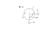
- a rotation angle detection device shown in FIG. 12 is known.
- the rotation angle detection device includes a rotor 1 including a magnet having two magnetic poles N and S, and two magnetic sensors 11 and 12 arranged at an angular interval of 90 ° about the rotation center axis of the rotor 1. Including.
- Each magnetic sensor 11, 12 outputs a sine wave signal having a phase difference of 90 °.
- the rotation angle detection device detects the rotation angle of the rotor 1 based on these two sine wave signals.
- the direction indicated by the arrow in FIG. 12 is the positive rotation direction of the rotor 1.
- the rotation angle of the rotor 1 is increased.
- A1 and A2 each represent an amplitude.
- one output signal V1 is V1.
- V2 A ⁇ cos ⁇
- the rotation angle ⁇ of the rotor can be obtained based on, for example, the following equation (1) using both output signals V1 and V2.
- an object of the present invention is to provide a rotation angle detection device that can improve detection accuracy. Further, in the conventional rotation angle detection device as described above, there is a possibility that a detection error may occur due to the influence of noise included in the output signal of the magnetic sensor. Therefore, in order to reduce such a detection error, it is conceivable to obtain the final rotation angle by averaging the rotation angle detected based on the output signal of the magnetic sensor in the time direction. However, if this is done, when the rotor rotates at a high speed, the response of rotation angle detection becomes poor.
- an object of the present invention is to provide a rotation angle detection device capable of reducing detection error due to the influence of noise while maintaining high responsiveness.
- the first rotation angle detection device of the present invention outputs first, second and third sine wave signals having phase differences from each other in accordance with the rotation of the rotating body (1).
- a rotation angle detection device (20, 70) that includes third sensors (11-13, 61-63) and detects the rotation angle of the rotating body based on the output signals of these sensors, wherein the first sensor A combination of the second sine wave signal and the second sine wave signal, a combination of the second sine wave signal and the third sine wave signal, and the second sine wave signal and the third sine wave signal.
- Rotation angle calculation means (21, 22) for calculating a rotation angle corresponding to the rotation angle of the rotating body based on two sine wave signals included in the combination of two or more of the combinations 71-73) and the rotation angle calculation means The using a plurality of rotation angle, and a final rotation angle calculation means for calculating a final rotation angle (23,74).
- alphanumeric characters in parentheses indicate corresponding components in the embodiments described later. However, this does not intend that the present invention should be construed as being limited to the embodiment.
- Rotational angle calculated from two sine wave signals having a phase difference from each other has a rotational angle range in which a calculation error increases due to an arithmetic expression used for the calculation. Since the plurality of rotation angles calculated by the rotation angle calculation means are calculated from different combinations of sine wave signals, the calculation formulas used for these calculations are different. For this reason, the range of the rotation angle where the calculation error increases is different between the plurality of rotation angles. According to the above configuration, it is possible to calculate a rotation angle with less calculation error using a plurality of rotation angles. For this reason, the detection accuracy of the rotation angle can be increased.
- the final rotation angle is calculated based on a plurality of rotation angles calculated by the rotation angle calculation means, so that detection errors due to the influence of noise included in the sensor output signal are reduced. it can.
- the rotation angle calculation means calculates a first rotation angle corresponding to the rotation angle of the rotating body based on the first sine wave signal and the second sine wave signal. Based on the first rotation angle calculating means (21), the second sine wave signal, and the third sine wave signal, the second rotation angle corresponding to the rotation angle of the rotating body is calculated. 2 rotation angle calculation means (22). Then, the final rotation angle calculation means calculates a final rotation angle using the first rotation angle and the second rotation angle.
- the first rotation angle corresponding to the rotation angle of the rotating body is calculated based on the first sine wave signal and the second sine wave signal.
- a second rotation angle corresponding to the rotation angle of the rotating body is calculated based on the second sine wave signal and the third sine wave signal.
- the final rotation angle is calculated using the first rotation angle and the second rotation angle.
- the rotation angle calculated from two sine wave signals having a phase difference from each other has a rotation angle range in which a calculation error increases due to an arithmetic expression used for the calculation.
- the first rotation angle is calculated from the first sine wave signal and the second sine wave signal
- the second rotation angle is calculated from the second sine wave signal and the third sine wave signal.
- the arithmetic expression used for the calculation is different.
- the first rotation angle and the second rotation angle have different rotation angle ranges in which a calculation error increases. According to the above configuration, it is possible to calculate a rotation angle with less calculation error using the first rotation angle and the second rotation angle. For this reason, the detection accuracy of the rotation angle can be increased.
- the final rotation angle calculation means is based on a rotation angle estimation means (31) for estimating a rotation angle of the rotating body, and a rotation angle estimation value estimated by the rotation angle estimation means.
- calculating means (32) for calculating a final rotation angle using the first rotation angle and the second rotation angle.
- the calculation means (32) determines a rotation angle with a smaller calculation error out of the first rotation angle and the second rotation angle in accordance with the rotation angle estimated value estimated by the rotation angle estimation means.
- the final rotation angle may be selected.
- the calculation means finally adds the weighting according to the rotation angle estimated value estimated by the rotation angle estimation means to each of the first rotation angle and the second rotation angle, and adds them.
- a simple rotation angle may be obtained.
- the rotation angle estimation means (31) may calculate an average value of the first rotation angle and the second rotation angle as the rotation angle estimation value.
- the rotation angle estimation value for example, a first rotation angle, a second rotation angle, or the like can be used.
- the currently selected first or second rotation angle is set as the rotation angle estimated value. You may make it use as.
- the last rotation angle calculated last time may be used as the current rotation angle estimation value.
- the rotation angle calculation means calculates a first rotation angle corresponding to the rotation angle of the rotating body based on the first sine wave signal and the second sine wave signal. Based on the first rotation angle calculation means (71) for calculating, the first sine wave signal, and the third sine wave signal, a second rotation angle corresponding to the rotation angle of the rotating body is calculated. Based on the second rotation angle calculation means (72), the second sine wave signal, and the third sine wave signal, a third rotation angle is calculated that corresponds to the rotation angle of the rotating body. Rotation angle calculation means (73). The final rotation angle calculation means calculates a final rotation angle based on the first, second, and third rotation angles.
- the first rotation angle corresponding to the rotation angle of the rotating body is calculated based on the first sine wave signal and the second sine wave signal.
- a second rotation angle corresponding to the rotation angle of the rotating body is calculated based on the first sine wave signal and the third sine wave signal.
- a third rotation angle corresponding to the rotation angle of the rotating body is calculated based on the second sine wave signal and the third sine wave signal.
- a final rotation angle is calculated based on the first, second, and third rotation angles.
- the average value or median value of the first, second, and third rotation angles can be calculated as the final rotation angle.
- the most out of the first, second, and third rotation angles can be excluded, and the other two average values can be calculated as the final rotation angle.
- the same sensor output signal is shared for calculation of a plurality of rotation angles.
- the first sine wave signal is shared for the calculation of the first rotation angle and the second rotation angle
- the second sine wave signal is the first rotation angle and the third rotation.
- the third sine wave signal is shared for calculating the angle
- the third sine wave signal is shared for calculating the second rotation angle and the third rotation angle.
- the sine wave signal V2 is output.
- the sine wave signal V3 is output.
- the first rotation angle calculation means obtains the first rotation angle ⁇ 1 by the following equation (i).
- the second rotation angle calculation means obtains the second rotation angle ⁇ 2 by the following equation (ii).
- the third rotation angle calculation means obtains the third rotation angle ⁇ 3 by the following equation (iii).
- the first rotation angle ⁇ 1 is obtained by the equation (i)
- the second rotation angle ⁇ 2 is obtained by the equation (ii)
- the third rotation angle ⁇ 3 is obtained by the equation (iii). Desired.
- a final rotation angle is calculated based on the first, second, and third rotation angles obtained in this way.
- the first and second sensors (11) that respectively output first and second sine wave signals having a phase difference according to the rotation of the rotating body (1).
- a rotation angle detection device for detecting the rotation angle of the rotating body based on the output signals of these sensors, wherein the first sine wave signal and the second sine wave signal And a first rotation angle calculation means (41) for calculating a first rotation angle corresponding to the rotation angle of the rotating body using a predetermined first calculation formula, and the first sine wave Based on the signal and the second sine wave signal, a second rotation angle corresponding to the rotation angle of the rotating body is calculated using a predetermined second calculation formula different from the first calculation formula. Using the second rotation angle calculating means (42), the first rotation angle and the second rotation angle. The rotational angle and a final rotation angle calculation means for calculating (43).
- a first rotation angle corresponding to the rotation angle of the rotating body is calculated using a predetermined first calculation formula.
- a second calculation expression that is different from the first calculation expression is used, and a second value corresponding to the rotation angle of the rotating body is obtained. The rotation angle is calculated. Then, the final rotation angle is calculated using the first rotation angle and the second rotation angle.
- Rotational angle calculated from two sine wave signals having a phase difference from each other has a rotational angle range in which a calculation error increases due to an arithmetic expression used for the calculation.
- the first rotation angle and the second rotation angle have different calculation formulas used for the calculation, and therefore the rotation angle range in which the calculation error increases is different. According to the above configuration, it is possible to calculate a rotation angle with less calculation error using the first rotation angle and the second rotation angle. For this reason, the detection accuracy of the rotation angle can be increased.
- the final rotation angle calculation means is based on a rotation angle estimation means (51) for estimating a rotation angle of the rotating body, and a rotation angle estimation value estimated by the rotation angle estimation means.
- calculating means (52) for calculating a final rotation angle using the first rotation angle and the second rotation angle.
- the calculation means (52) selects a rotation angle having a smaller calculation error, out of the first rotation angle and the second rotation angle, according to the rotation angle estimated value estimated by the rotation angle estimation means.
- the final rotation angle may be selected.
- the calculation means finally adds the weighting according to the rotation angle estimated value estimated by the rotation angle estimation means to each of the first rotation angle and the second rotation angle, and adds them.
- a simple rotation angle may be obtained.
- the rotation angle estimation means (51) may calculate an average value of the first rotation angle and the second rotation angle as the rotation angle estimation value.
- the rotation angle estimation value for example, a first rotation angle, a second rotation angle, or the like can be used.
- the currently selected first or second rotation angle is set as the rotation angle estimated value. You may make it use as.
- the last rotation angle calculated last time may be used as the current rotation angle estimation value.
- FIG. 1 is a schematic diagram showing a configuration of a rotation angle detection device according to the first embodiment of the present invention.
- FIG. 2 is an explanatory diagram for explaining a range in which a calculation error of the first rotation angle is large.
- FIG. 3 is an explanatory diagram for explaining a range in which the calculation error of the second rotation angle is large.
- FIG. 4 is an explanatory diagram for explaining the operation of the rotation angle selection unit.
- FIG. 5 is a flowchart showing a procedure of rotation angle calculation processing by the rotation angle calculation device.
- FIG. 6 is a schematic diagram showing a configuration of a rotation angle detection device according to the second embodiment of the present invention.
- FIG. 7 is a flowchart showing a procedure of rotation angle calculation processing by the rotation angle calculation device.
- FIG. 8 is an explanatory diagram for explaining a method of calculating a final rotation angle by adding a weight to the first rotation angle and the second rotation angle.
- FIG. 9 is a schematic diagram showing a configuration of a rotation angle detection device according to the third embodiment of the present invention.
- FIG. 10 is a functional block diagram showing a detailed configuration of the rotation angle calculation device.
- FIG. 11 is a flowchart illustrating a procedure of rotation angle calculation processing by the rotation angle calculation device.
- FIG. 12 is a schematic diagram for explaining a rotation angle detection method by a conventional rotation angle detection device.
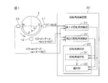
- FIG. 1 is a schematic diagram showing a configuration of a rotation angle detection device according to the first embodiment of the present invention.
- This rotation angle detection device can be used, for example, to detect the rotation angle of a rotor of a brushless motor of an electric power steering device.
- the rotation angle detection device has, for example, a detection rotor 1 (hereinafter referred to as “rotor 1”) that rotates according to the rotation of a brushless motor.
- the rotor 1 includes a magnet having two magnetic poles N and S. The same applies to the rotation angle detection devices according to second and third embodiments described later.
- three magnetic sensors 11, 12, and 13 are arranged at intervals in the circumferential direction of the rotor 1. These three magnetic sensors 11, 12, and 13 may be referred to as a first magnetic sensor 11, a second magnetic sensor 12, and a third magnetic sensor 13, respectively.
- a sensor provided with an element having a characteristic in which an electrical characteristic is changed by the action of a magnetic field such as a Hall element or a magnetoresistive element (MR element) can be used.
- the first magnetic sensor 11 and the second magnetic sensor 12 are arranged with an angular interval ⁇ around the rotation center axis of the rotor 1.
- the first magnetic sensor 11 and the third magnetic sensor 13 are arranged with an angular interval of ⁇ larger than ⁇ around the rotation center axis of the rotor 1.
- ⁇ is set to 90 ° and ⁇ is set to 180 °. Therefore, in this embodiment, the angular interval between the second magnetic sensor 12 and the third magnetic sensor 13 is 90 °.
- the direction indicated by the arrow in FIG. 1 is the positive rotation direction of the rotor 1.
- the rotation angle of the rotor 1 is increased.
- the rotation angle of the rotor 1 is decreased.
- A1, A2, and A3 represent amplitudes, respectively.
- each signal V1, V2 and V3 are expressed as A ⁇ sin ⁇ , A ⁇ sin ( ⁇ + ⁇ ) and A ⁇ sin ( ⁇ + ⁇ ), respectively.
- A 1
- the signals V1, V2, and V3 are expressed as sin ⁇ , sin ( ⁇ + ⁇ ), and sin ( ⁇ + ⁇ ), respectively.
- V1 sin ⁇
- the output signals V1, V2, and V3 of the magnetic sensors 11, 12, and 13 are input to the rotation angle calculation device 20.
- the rotation angle calculation device 20 calculates the rotation angle ⁇ of the rotor 1 based on the output signals V1, V2, and V3 of the magnetic sensors 11, 12, and 13.
- the rotation angle calculation device 20 is composed of, for example, a microcomputer, and includes a CPU (Central Processing Unit) and a memory (ROM, RAM, etc.).
- the rotation angle calculation device 20 functions as a plurality of function processing units when the CPU executes a predetermined program stored in the ROM.
- the plurality of function processing units include a first rotation angle calculation unit (first rotation angle calculation unit) 21, a second rotation angle calculation unit (second rotation angle calculation unit) 22, and a rotation angle selection unit (final rotation angle). Computing means) 23.
- the first rotation angle calculation unit 21 is configured to output a first rotation angle corresponding to the rotation angle of the rotor 1 based on the output signal V 1 of the first magnetic sensor 11 and the output signal V 2 of the second magnetic sensor 12. Calculate ⁇ 1 .
- the second rotation angle calculation unit 22 is a second rotation angle corresponding to the rotation angle of the rotor 1 based on the output signal V2 of the second magnetic sensor 12 and the output signal V3 of the third magnetic sensor 13. ⁇ 2 is calculated.
- the rotation angle selector 23 selects one of the first rotation angle ⁇ 1 and the second rotation angle ⁇ 2 as the final rotation angle ⁇ according to the estimated rotation angle value of the rotor 1. .
- the concept of rotation angle selection by the rotation angle selection unit 23 will be described.
- the rotation angle ⁇ of the rotor 1 has a range in the vicinity of 90 ° (for example, a range of 90 ° ⁇ 22.5 °) and a range in the vicinity of 270 ° (for example, 270 ° ⁇ In the range of 22.5 °, the absolute value of sin ( ⁇ + 90 °) becomes small, and the calculation error of the first rotation angle ⁇ 1 becomes large.
- a range near 0 ° eg, a range from 0 ° to 22.5 °
- a range around 180 ° eg, a range of 180 ° ⁇ 22.5 °
- a range around 360 ° eg, 337.5 In the range of ⁇ 360 °, the absolute value of sin ( ⁇ + 180 °) is small.
- the calculation error of the second rotation angle ⁇ 2 becomes large.
- the rotation angle selection unit 23 estimates the rotation angle of the rotor 1 from the first rotation angle ⁇ 1 and the second rotation angle ⁇ 2 and responds to the estimated rotation angle (rotation angle estimated value).
- the one that is estimated to have a small calculation error (high calculation accuracy) is selected as the final rotation angle ⁇ from the first rotation angle ⁇ 1 and the second rotation angle ⁇ 2 .
- the rotation angle selection unit 23 includes a rotation angle estimation unit 31 and a selection unit 32.
- Selecting unit 32 using the rotation angle estimated value theta E obtained by the rotational angle estimation unit 31, in accordance with condition expressed by a following expression (5), the rotation angle of the first rotation angle theta 1 and the 2 theta 2 Is selected as the final rotation angle ⁇ .
- FIG. 4 shows the change of sin ⁇ / sin ( ⁇ + 90 ° ) with respect to the rotation angle estimated value theta E, and a change in sin ( ⁇ + 90 °) / sin ( ⁇ + 180 °) with respect to the rotation angle estimated value theta E.
- tan ⁇ 1 ⁇ (sin ⁇ °) / sin ( ⁇ + 90 °) ⁇ is used to calculate the first rotation angle ⁇ 1 and tan ⁇ 1 ⁇ (sin ( ⁇ + 90 °) / sin ( ⁇ + 180 °) ⁇ is used to calculate the second rotation angle ⁇ 2 .
- the rotation angle estimated value ⁇ The rotation angle calculated using the thick line portion (high calculation accuracy portion) of the curve corresponding to E is selected as the final rotation angle ⁇ .
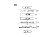
- FIG. 5 is a flowchart showing the procedure of the rotation angle calculation process executed by the rotation angle calculation device 20.
- the rotation angle calculation process is repeated every predetermined calculation cycle.
- the first rotation angle calculation unit 21 of the rotation angle calculation device 20 calculates the first rotation angle ⁇ 1 based on the equation (2) using the output signals V1 and V2 captured in step S1. (Step S2).
- the second rotation angle calculation unit 22 of the rotation angle calculation device 20 calculates the second rotation angle ⁇ 2 based on the expression (3) using the output signals V2 and V3 taken in step S1. (Step S3). Further, the rotation angle selection unit 23 of the rotation angle calculation unit 20 calculates the rotation angle estimated value theta E based on the first rotation angle theta 1 and second and the rotational angle theta 2 (step S4). For example, the rotation angle selection unit 23 obtains the average value of the first rotation angle ⁇ 1 and the second rotation angle ⁇ 2 as the rotation angle estimated value ⁇ E based on the equation (4).
- the rotation angle selection unit 23 using the rotation angle estimated value theta E, according to the conditional expression in the equation (5), one of a first rotation angle theta 1 and the second rotation angle theta 2, Select as the final rotation angle ⁇ . (Step S5).
- the rotation angle with the smaller calculation error is selected as the final rotation angle ⁇ of the rotor 1.
- the detection accuracy of the rotation angle ⁇ can be increased.
- three magnetic sensors are provided.
- four or more magnetic sensors are provided, and a rotation angle corresponding to the rotation angle ⁇ of the rotor 1 is calculated for each set of two adjacent sensors.
- three or more types of rotation angles that are candidates for the final rotation angle ⁇ may be obtained, and one of these rotation angle candidates may be selected as the final rotation angle ⁇ .
- FIG. 6 is a schematic diagram showing a configuration of a rotation angle detection device according to the second embodiment of the present invention.
- two magnetic sensors 11 and 12 are arranged at intervals in the circumferential direction of the rotor 1. These two magnetic sensors 11 and 12 may be referred to as a first magnetic sensor 11 and a second magnetic sensor 12, respectively.
- the first magnetic sensor 11 and the second magnetic sensor 12 are arranged at an angular interval of ⁇ around the rotation center axis of the rotor 1. In this embodiment, ⁇ is set to 90 °.
- the direction indicated by the arrow in FIG. 6 is the positive rotation direction of the rotor 1.
- the output signals V1 and V2 of the magnetic sensors 11 and 12 are input to the rotation angle calculation device 40.
- the rotation angle calculation device 40 calculates the rotation angle ⁇ of the rotor 1 based on the output signals V1 and V2 of the magnetic sensors 11 and 12.
- the rotation angle calculation device 40 is composed of, for example, a microcomputer and includes a CPU (Central Processing Unit) and a memory (ROM, RAM, etc.).
- the rotation angle calculation device 40 functions as a plurality of function processing units when the CPU executes a predetermined program stored in the ROM.
- the plurality of function processing units include a first rotation angle calculation unit (first rotation angle calculation unit) 41, a second rotation angle calculation unit (second rotation angle calculation unit) 42, and a rotation angle selection unit (final rotation angle). Computing means) 43.
- the first rotation angle calculation unit 41 is based on the output signal V1 of the first magnetic sensor 11 and the output signal V2 of the second magnetic sensor 12, and the calculation formula (hereinafter, “The first rotation angle ⁇ 1 corresponding to the rotation angle of the rotor 1 is calculated using “first calculation formula”.
- the first arithmetic expression is the same as the expression (2) described in the first embodiment.
- the second rotation angle calculation unit 42 calculates an expression (hereinafter, “The second rotation angle ⁇ 2 corresponding to the rotation angle of the rotor 1 is calculated using a “second calculation formula”.
- the rotation angle selection unit 43 selects one of the first rotation angle ⁇ 1 and the second rotation angle ⁇ 2 as the final rotation angle ⁇ according to the estimated rotation angle value of the rotor 1. .
- the rotation angle ⁇ of the rotor 1 is in the range near 90 ° (for example, the range of 90 ° ⁇ 22.5 °).
- a range around 270 ° for example, a range of 270 ° ⁇ 22.5 °
- the calculation error of the first rotation angle ⁇ 1 becomes large.
- V1 ′ sin ( ⁇ + 180 °)
- V1 ′ sin ( ⁇ + 180 °)
- the rotation angle selection unit 43 estimates the rotation angle of the rotor 1 from the first rotation angle ⁇ 1 and the second rotation angle ⁇ 2, and responds to the estimated rotation angle (rotation angle estimated value).
- the rotation angle selection unit 43 includes a rotation angle estimation unit 51 and a selection unit 52.
- the rotation angle estimation unit 51 calculates the average rotation angle ⁇ 1 and the second rotation angle ⁇ 2 based on the following equation (8) to obtain the rotation angle estimation value ⁇ E. .
- ⁇ E ( ⁇ 1 + ⁇ 2 ) / 2 (8)
- Selecting unit 52 using the rotation angle estimated value theta E obtained by the rotational angle estimation unit 51, in accordance with condition expressed by a following expression (9), the rotation angle of the first rotation angle theta 1 and the 2 theta 2 Is selected as the final rotation angle ⁇ .
- This conditional expression is the same as the conditional expression in the first embodiment (see the expression (5)).
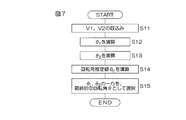
- FIG. 7 is a flowchart showing the procedure of the rotation angle calculation process executed by the rotation angle calculation device 40.
- the rotation angle calculation process is repeated every predetermined calculation cycle.
- the first rotation angle calculation unit 41 of the rotation angle calculation device 40 uses the output signals V1 and V2 fetched in step S11, and based on the first calculation formula shown in the formula (6), It computes the rotation angle theta 1 of (step S12).
- the second rotation angle calculation unit 42 of the rotation angle calculation device 40 uses the output signals V1 and V2 fetched in step S11, and based on the second calculation formula shown in the formula (7), calculates the rotation angle theta 2 (step S13). Further, the rotation angle selection unit 43 of the rotation angle calculation unit 40 calculates the rotation angle estimated value theta E based on the first rotation angle theta 1 and second and the rotational angle theta 2 (step S14). For example, the rotation angle selection unit 43 obtains the average value of the first rotation angle ⁇ 1 and the second rotation angle ⁇ 2 as the rotation angle estimated value ⁇ E based on the equation (8).
- the rotation angle selection unit 43 uses the rotation angle estimated value ⁇ E and determines one of the first rotation angle ⁇ 1 and the second rotation angle ⁇ 2 in accordance with the conditional expression of the equation (9). Select as the final rotation angle ⁇ . (Step S15).
- the rotation angle with the smaller calculation error out of the first rotation angle ⁇ 1 and the second rotation angle ⁇ 2 is selected as the final rotation angle ⁇ of the rotor 1. Will be able to. For this reason, the detection accuracy of the rotation angle ⁇ can be increased.
- two types of rotation angles ⁇ 1 and ⁇ 2 can be calculated from the output signals V 1 and V 2 of the two magnetic sensors 11 and 12, which have different angle ranges in which the calculation error increases. Therefore, there is an advantage that the number of magnetic sensors can be reduced as compared with the first embodiment.
- one of the first rotation angle ⁇ 1 and the second rotation angle ⁇ 2 is finally determined according to the rotation angle estimated value ⁇ E.
- the final rotation angle is obtained by adding a weight corresponding to the estimated rotation angle ⁇ E to each of the first rotation angle ⁇ 1 and the second rotation angle ⁇ 2. You may make it obtain
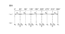
- the formula (5) the angle when selecting the rotation angle according to the conditional expression, where the angular range in which the first rotation angle theta 1 is selected, the second rotation angle theta 2 is selected in (9)
- the range is as shown in FIG. Therefore, as shown in FIG. 8B, the rotation angle estimated value ⁇ E is not 0 ° (360 °) or 180 °, which is the median value of the range in which the first rotation angle ⁇ 1 is selected. Then, the first rotation angle ⁇ 1 is set as the final rotation angle ⁇ .
- the second rotation angle is the final rotation angle ⁇ . ⁇ 2 is set.
- the weights w 1 and w 2 are obtained based on the following equation (10).
- the rotation angle estimation value ⁇ E is obtained by calculating the average of the first rotation angle ⁇ 1 and the second rotation angle ⁇ 2 .
- one of the rotation angle theta 1 or the second rotation angle theta 2 may be used as the rotation angle estimated value theta E.
- the currently selected first or second rotation angle You may make it use (theta) 1, ( theta) 2 as rotation angle estimated value (theta) E.
- the final rotation angle in after the first operation, a theta final rotation angle is previously calculated may be used as the current rotation angle estimated value theta E.
- FIG. 9 is a schematic diagram showing a configuration of a rotation angle detection device according to the third embodiment of the present invention.
- three magnetic sensors 61, 62, 63 are arranged at intervals in the circumferential direction of the rotor 1. These three magnetic sensors 61, 62, and 63 may be referred to as a first magnetic sensor 61, a second magnetic sensor 62, and a third magnetic sensor 63, respectively.
- the first magnetic sensor 61 and the second magnetic sensor 62 are arranged at an angular interval of ⁇ around the rotation center axis of the rotor 1.
- ⁇ is set to 30 °, for example.
- the first magnetic sensor 61 and the third magnetic sensor 63 are arranged with an angular interval of ⁇ larger than ⁇ around the rotation center axis of the rotor 1.
- ⁇ is set to 60 °, for example. Therefore, the angular interval between the second magnetic sensor 62 and the third magnetic sensor 63 is ( ⁇ ). In this example, ( ⁇ ) is 30 °.
- the direction indicated by the arrow in FIG. 9 is the positive rotation direction of the rotor 1.
- the output signals V1, V2, and V3 of the magnetic sensors 61, 62, and 63 are input to the rotation angle calculation device 70.
- the rotation angle calculation device 70 calculates the rotation angle ⁇ of the rotor 1 based on the output signals V1, V2, V3 of the magnetic sensors 61, 62, 63.
- the rotation angle calculation device 70 is composed of, for example, a microcomputer and includes a CPU (central processing unit) and a memory (ROM, RAM, etc.).
- the rotation angle calculation device 70 functions as a plurality of function processing units when the CPU executes a predetermined program stored in the ROM.
- the plurality of function processing units include a first rotation angle calculation unit (first rotation angle calculation unit) 71, a second rotation angle calculation unit (second rotation angle calculation unit) 72, and a third rotation angle calculation unit ( A third rotation angle calculation means) 73 and a final rotation angle calculation section (final rotation angle calculation means) 74.
- the first rotation angle calculation unit 71 is a first rotation angle corresponding to the rotation angle of the rotor 1 based on the output signal V1 of the first magnetic sensor 61 and the output signal V2 of the second magnetic sensor 62. Calculate ⁇ 1 .
- the second rotation angle calculation unit 72 generates a second rotation angle corresponding to the rotation angle of the rotor 1 based on the output signal V1 of the first magnetic sensor 61 and the output signal V3 of the third magnetic sensor 63.
- ⁇ 2 is calculated.
- the third rotation angle calculation unit 73 is a third rotation angle corresponding to the rotation angle of the rotor 1 based on the output signal V2 of the second magnetic sensor 62 and the output signal V3 of the third magnetic sensor 63. to calculate the ⁇ 3.
- the final rotation angle calculation unit 74 includes first, second, and third rotation angles ⁇ 1 , ⁇ 2 , ⁇ 3 calculated by the first, second, and third rotation angle calculation units 71, 72, 73, respectively. Based on the above, the final rotation angle ⁇ is calculated.
- FIG. 10 is a functional block diagram showing a more detailed configuration of the rotation angle calculation device 70.
- the first rotation angle calculation unit 71 includes a signal generation unit 81 and an angle calculation unit 82.
- the signal generator 81 on the basis of the following equation (11), generates a signal V 12.
- the said Formula (11) can be derived
- the second rotation angle calculation unit 72 includes a signal generation unit 91 and an angle calculation unit 92.
- the signal generator 91 generates the signal V 13 based on the following equation (13).
- cos ⁇ and sin ⁇ are stored in the memory in advance.
- the said Formula (13) can be derived
- the third rotation angle calculation unit 73 includes a signal generation unit 101, an angle calculation unit 102, and an angle calculation unit 103.
- the signal generator 101 based on the following equation (15), generates a signal V 23.
- cos ( ⁇ ) and sin ( ⁇ ) are stored in the memory in advance.
- the angle calculation unit 103 calculates the third rotation angle ⁇ 3 based on the following equation (17).
- the final rotation angle calculation unit 74 calculates the final rotation angle ⁇ based on, for example, the following equation (18). That is, the final rotation angle calculation unit 74 calculates the average value of the first, second, and third rotation angles ⁇ 1 , ⁇ 2 , ⁇ 3 as the final rotation angle ⁇ .
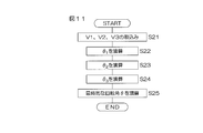
- FIG. 11 is a flowchart showing the procedure of the rotation angle calculation process executed by the rotation angle calculation device 70.
- the rotation angle calculation process is repeated every predetermined calculation cycle.
- the first rotation angle calculation unit 71 of the rotation angle calculation device 70 outputs the output signals V1 and V2 fetched in step S21, the values of sin ⁇ and cos ⁇ stored in the memory, the equation (11), (12) and is used to computing the first rotation angle theta 1 (step S22).
- the second rotation angle calculation unit 72 of the rotation angle calculation device 70 outputs the output signals V1 and V3 fetched in step S21, the values of sin ⁇ and cos ⁇ stored in the memory, the equation (13), (14) and is used to computing the second rotation angle theta 2 (step S23).
- the third rotation angle calculation unit 73 of the rotation angle calculation device 70 outputs the output signals V2 and V3 taken in step S21, and ⁇ , sin ( ⁇ ) and cos ( ⁇ ) stored in the memory.
- the third rotation angle ⁇ 3 is calculated using the value of ⁇ ) and the equations (15), (16), and (17) (step S24).
- the final rotation angle calculation unit 74 of the rotation angle calculation device 70 calculates the final rotation angle ⁇ based on the first, second, and third rotation angles ⁇ 1 , ⁇ 2 , ⁇ 3 (step) S25). For example, the final rotation angle calculation unit 74 sets the average value of the first, second, and third rotation angles ⁇ 1 , ⁇ 2 , ⁇ 3 as the final rotation angle ⁇ based on the equation (18). Calculate. In the third embodiment, the average value of the three rotation angles ⁇ 1 , ⁇ 2 , ⁇ 3 is obtained as the final rotation angle ⁇ . For this reason, the detection error due to the influence of noise included in the output signal of the magnetic sensor can be reduced.
- the final rotation angle ⁇ is calculated based on the three rotation angles ⁇ 1 , ⁇ 2 , ⁇ 3 calculated from the output signals V1, V2, and V3 generated at the same time. Compared with the case of calculating the final rotation angle by averaging the rotation angles, no time delay occurs in the rotation angle detection. For this reason, even when the rotational speed of the rotor 1 is high, high responsiveness can be realized. That is, according to the embodiment, it is possible to reduce detection errors due to the influence of noise while maintaining high responsiveness.
- the output signal of the same magnetic sensor is used for calculating a plurality of rotation angles. Shared. Specifically, the signal V1 is shared for calculating ⁇ 1 and ⁇ 2 , the signal V2 is shared for calculating ⁇ 1 and ⁇ 3 , and the signal V3 is used for calculating ⁇ 2 and ⁇ 3. It is shared with. For this reason, there is an advantage that the number of magnetic sensors can be reduced as compared with a case where output signals of the same magnetic sensor are not shared for a plurality of rotation angle calculations. Specifically, when three types of rotation angles are calculated as described above, if the same output signal of the magnetic sensor is not used for calculation of a plurality of rotation angles, six magnetic sensors are required. In this embodiment, three is sufficient.
- the final rotation angle calculation unit 74 calculates the average of the three rotation angles ⁇ 1 , ⁇ 2 , ⁇ 3 as the final rotation angle ⁇ .
- the median value among ⁇ 1 , ⁇ 2 , and ⁇ 3 may be calculated as the final rotation angle ⁇ .
- the final rotation angle calculation unit 74 excludes the most out of the three rotation angles ⁇ 1 , ⁇ 2 , ⁇ 3 and calculates the other two average values as the final rotation angle ⁇ . You may make it do.
- the average value of the median value of the three rotation angles ⁇ 1 , ⁇ 2 , ⁇ 3 and the difference between the median value of the other two rotation angles is finally determined.
- the rotation angle ⁇ is assumed.
- three magnetic sensors are provided.
- four or more magnetic sensors may be provided.
- the present invention can also be applied when detecting the rotation angle of a rotating body other than the rotor of a brushless motor.
Abstract
第1の回転角演算部21は、第1の磁気センサ11の出力信号V1と、第2の磁気センサ12の出力信号V2とに基づいて、ロータ1の回転角に相当する第1の回転角θ1を演算する。第2の回転角演算部22は、第2の磁気センサ12の出力信号V2と、第3の磁気センサ13の出力信号V3とに基づいて、ロータ1の回転角に相当する第2の回転角θ2を演算する。回転角選択部23は、第1の回転角θ1と第2の回転角θ2とを用いて最終的な回転角θを求める。
Description
この発明は、回転体の回転角を検出する回転角検出装置に関する。
電動パワーステアリング装置などに使用されるブラシレスモータは、ロータの回転角度に合わせてステータ巻線に電流を通電することによって制御される。そこで、たとえば、図12に示す回転角検出装置が知られている。回転角検出装置は、2つの磁極N,Sを有する磁石を含むロータ1と、ロータ1の回転中心軸を中心として90°の角度間隔をおいて配置された2つの磁気センサ11,12とを含む。各磁気センサ11,12は、互いに90°の位相差を有する正弦波信号を出力する。回転角検出装置は、これらの2つの正弦波信号に基づいてロータ1の回転角を検出する。
図12に矢印で示す方向をロータ1の正方向の回転方向とする。そして、ロータ1が正方向に回転されるとロータ1の回転角が大きくなり、ロータ1が逆方向に回転されると、ロータ1の回転角が小さくなるものとする。ロータ1の回転角θに対して、一方の磁気センサ11からV1=A1・sinθの出力信号V1が出力されるとすると、他方の磁気センサ12からは、V2=A2・sin(θ+90°)=A2・cosθの出力信号V2が出力される。A1,A2は、それぞれ振幅を表している。
これらの振幅A1,A2が互いに等しい値Aであるとみなすか、あるいは両振幅が所定の規定値Aとなるように両信号S1,S2を正規化したとすると、一方の出力信号V1は、V1=A・sinθと表され、他方の出力信号V2は、V2=A・cosθと表される。さらに、A=1とすると、一方の出力信号V1は、V1=sinθで表され、他方の出力信号V2は、V2=cosθで表される。そこで、説明を簡単にするために、磁気センサ11,12の出力信号V1,V2を、V1=sinθ、V2=sin(θ+90°)=cosθで表すことにする。
ロータの回転角θは、両出力信号V1,V2を用いて、たとえば、次式(1)に基づいて求めることができる。
θ=tan-1(sinθ/cosθ)
=tan-1(sinθ/sin(θ+90°))
=tan-1(V1/V2)…(1)
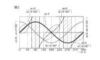
図2は、ロータ1の回転角θに対する、磁気センサ11,12の出力信号V1(=sinθ),V2(=sin(θ+90°))および前記式(1)の右辺におけるsinθ/sin(θ+90°)の変化を示している。
θ=tan-1(sinθ/cosθ)
=tan-1(sinθ/sin(θ+90°))
=tan-1(V1/V2)…(1)
図2は、ロータ1の回転角θに対する、磁気センサ11,12の出力信号V1(=sinθ),V2(=sin(θ+90°))および前記式(1)の右辺におけるsinθ/sin(θ+90°)の変化を示している。
前述したような従来の回転角検出装置においては、前記式(1)に基づいて、ロータ1の回転角θを演算する際、sinθ/cosθの分母になるcosθが零付近になると、演算誤差が大きくなる。したがって、図2に斜線部分で示すように、ロータ角度が90°付近の範囲内または270°付近の範囲内にある場合には、cosθ(=sin(θ+90°))の絶対値が小さくなるため、tan-1(sinθ/cosθ)に基づいて演算される回転角θの誤差が大きくなる。
そこで、この発明の目的は、検出精度を高めることができる回転角検出装置を提供することである。
また、前述したような従来の回転角検出装置においては、磁気センサの出力信号に含まれるノイズの影響によって検出誤差が発生するおそれがある。そこで、このような検出誤差を低減させるために、磁気センサの出力信号に基づいて検出される回転角を時間方向に平均化することによって、最終的な回転角を求めることが考えられる。しかし、このようにすると、ロータが高速回転している場合には、回転角検出の応答性が悪くなる。
また、前述したような従来の回転角検出装置においては、磁気センサの出力信号に含まれるノイズの影響によって検出誤差が発生するおそれがある。そこで、このような検出誤差を低減させるために、磁気センサの出力信号に基づいて検出される回転角を時間方向に平均化することによって、最終的な回転角を求めることが考えられる。しかし、このようにすると、ロータが高速回転している場合には、回転角検出の応答性が悪くなる。
そこで、この発明の目的は、高い応答性を維持しつつ、ノイズの影響による検出誤差を低減できる回転角検出装置を提供することである。
この発明の第1の回転角検出装置は、回転体(1)の回転に応じて、互いに位相差を有する第1、第2および第3の正弦波信号をそれぞれ出力する第1、第2および第3のセンサ(11~13,61~63)を含み、これらのセンサの出力信号に基づいて前記回転体の回転角を検出する回転角検出装置(20,70)であって、前記第1の正弦波信号と前記第2の正弦波信号との組合せ、前記第2の正弦波信号と前記第3の正弦波信号との組合せおよび前記第2の正弦波信号と前記第3の正弦波信号との組合せのうちの2以上の組合せにおける組合せ毎に、その組合せに含まれる2つの正弦波信号に基づいて前記回転体の回転角に相当する回転角を演算する回転角演算手段(21,22,71~73)と、前記回転角演算手段によって演算された複数の回転角を用いて、最終的な回転角を演算する最終回転角演算手段(23,74)とを含む。なお、この項において括弧内の英数字は、後述の実施形態における対応構成要素等を表す。しかし、このことは、この発明が当該実施形態に限定して解釈されるべきことを意図するものではない。
互いに位相差を有する2つの正弦波信号から演算される回転角には、その演算に用いられる演算式に起因して、演算誤差が大きくなる回転角の範囲が存在する。回転角演算手段によって演算される複数の回転角は、正弦波信号の異なる組合せから演算されるので、それらの演算に用いられる演算式が異なる。このため、これらの複数の回転角間では、演算誤差が大きくなる回転角の範囲が異なる。上記構成によれば、複数の回転角を用いて、演算誤差の少ない回転角を演算することが可能となる。このため、回転角の検出精度を高めることができる。
また、この構成によれば、回転角演算手段によって演算される複数の回転角に基づいて、最終的な回転角が演算されるので、センサの出力信号に含まれるノイズの影響による検出誤差を低減できる。
この発明の一実施形態では、前記回転角演算手段は、第1の正弦波信号と前記第2の正弦波信号とに基づいて、前記回転体の回転角に相当する第1の回転角を演算する第1回転角演算手段(21)と、前記第2の正弦波信号と前記第3の正弦波信号とに基づいて、前記回転体の回転角に相当する第2の回転角を演算する第2回転角演算手段(22)とを含む。そして、前記最終回転角演算手段は、前記第1の回転角および前記第2の回転角を用いて、最終的な回転角を演算する。
この発明の一実施形態では、前記回転角演算手段は、第1の正弦波信号と前記第2の正弦波信号とに基づいて、前記回転体の回転角に相当する第1の回転角を演算する第1回転角演算手段(21)と、前記第2の正弦波信号と前記第3の正弦波信号とに基づいて、前記回転体の回転角に相当する第2の回転角を演算する第2回転角演算手段(22)とを含む。そして、前記最終回転角演算手段は、前記第1の回転角および前記第2の回転角を用いて、最終的な回転角を演算する。
この構成では、第1の正弦波信号と第2の正弦波信号とに基づいて、回転体の回転角に相当する第1の回転角が演算される。また、第2の正弦波信号と第3の正弦波信号とに基づいて、回転体の回転角に相当する第2の回転角が演算される。そして、第1の回転角および第2の回転角を用いて、最終的な回転角が演算される。
互いに位相差を有する2つの正弦波信号から演算される回転角には、その演算に用いられる演算式に起因して、演算誤差が大きくなる回転角の範囲が存在する。第1の回転角は第1の正弦波信号と第2の正弦波信号から演算され、第2の回転角は第2の正弦波信号と第3の正弦波信号から演算されるので、両者の演算に用いられる演算式が異なる。このため、第1の回転角と第2の回転角とでは、演算誤差が大きくなる回転角の範囲が異なる。上記構成によれば、第1の回転角および第2の回転角を用いて、演算誤差の少ない回転角を演算することが可能となる。このため、回転角の検出精度を高めることができる。
互いに位相差を有する2つの正弦波信号から演算される回転角には、その演算に用いられる演算式に起因して、演算誤差が大きくなる回転角の範囲が存在する。第1の回転角は第1の正弦波信号と第2の正弦波信号から演算され、第2の回転角は第2の正弦波信号と第3の正弦波信号から演算されるので、両者の演算に用いられる演算式が異なる。このため、第1の回転角と第2の回転角とでは、演算誤差が大きくなる回転角の範囲が異なる。上記構成によれば、第1の回転角および第2の回転角を用いて、演算誤差の少ない回転角を演算することが可能となる。このため、回転角の検出精度を高めることができる。
この発明の一実施形態では、前記最終回転角演算手段は、前記回転体の回転角を推定する回転角推定手段(31)と、前記回転角推定手段によって推定された回転角推定値に応じて、前記第1の回転角および前記第2の回転角を用いて、最終的な回転角を演算する演算手段(32)とを含む。
前記演算手段(32)は、前記回転角推定手段によって推定された回転角推定値に応じて、前記第1の回転角および前記第2の回転角のうち、演算誤差が小さい方の回転角を、最終的な回転角として選択するものであってもよい。あるいは、前記演算手段は、前記第1の回転角および前記第2の回転角それぞれに、前記回転角推定手段によって推定された回転角推定値に応じた重み付けをして加算することにより、最終的な回転角を求めるものであってもよい。
前記演算手段(32)は、前記回転角推定手段によって推定された回転角推定値に応じて、前記第1の回転角および前記第2の回転角のうち、演算誤差が小さい方の回転角を、最終的な回転角として選択するものであってもよい。あるいは、前記演算手段は、前記第1の回転角および前記第2の回転角それぞれに、前記回転角推定手段によって推定された回転角推定値に応じた重み付けをして加算することにより、最終的な回転角を求めるものであってもよい。
前記回転角推定手段(31)は、前記第1の回転角と前記第2の回転角との平均値を、前記回転角推定値として演算するものであってもよい。また、前記回転角推定値としては、たとえば、第1の回転角、第2の回転角などを用いることができる。また、第1の回転角と第2の回転角のいずれかが最終的な回転角として最初に選択された後においては、現在選択されている第1または第2の回転角を回転角推定値として用いるようにしてもよい。さらに、最終的な回転角が最初に演算された後においては、前回演算された最終的な回転角を、今回の回転角推定値として用いるようにしてもよい。
この発明の一実施形態では、前記回転角演算手段は、前記第1の正弦波信号と前記第2の正弦波信号とに基づいて、前記回転体の回転角に相当する第1の回転角を演算する第1回転角演算手段(71)と、前記第1の正弦波信号と前記第3の正弦波信号とに基づいて、前記回転体の回転角に相当する第2の回転角を演算する第2回転角演算手段(72)と、前記第2の正弦波信号と前記第3の正弦波信号とに基づいて、前記回転体の回転角に相当する第3の回転角を演算する第3回転角演算手段(73)とを含む。そして、前記最終回転角演算手段は、前記第1、第2および第3の回転角に基づいて、最終的な回転角を演算する。
この構成では、第1の正弦波信号と前記第2の正弦波信号とに基づいて、回転体の回転角に相当する第1の回転角が演算される。また、第1の正弦波信号と第3の正弦波信号とに基づいて、回転体の回転角に相当する第2の回転角が演算される。また、第2の正弦波信号と第3の正弦波信号とに基づいて、回転体の回転角に相当する第3の回転角が演算される。そして、第1、第2および第3の回転角に基づいて、最終的な回転角が演算される。具体的には、たとえば、第1、第2および第3の回転角の平均値または中央値を、最終的な回転角として演算することができる。また、第1、第2および第3の回転角のうち、最も外れているものを除外し、他の2つの平均値を、最終的な回転角として演算することもできる。
この構成によれば、第1、第2および第3の回転角に基づいて、最終的な回転角が演算されるので、センサの出力信号に含まれるノイズの影響による検出誤差を低減できる。また、最終的な回転角は、同時刻に発生したセンサ出力信号から演算された第1、第2および第3の回転角に基づいて演算されるので、回転角検出に時間遅れが発生しない。このため回転体の回転速度が大きい場合でも、高い応答性を実現できる。つまり、この構成によれば、高い応答性を維持しつつ、ノイズの影響による検出誤差を低減できる。
また、この構成では、第1、第2および第3の回転角を演算する場合に、同じセンサの出力信号を複数の回転角演算のために共用している。具体的には、第1の正弦波信号は、第1の回転角および第2の回転角の演算のために共用され、第2の正弦波信号は、第1の回転角および第3の回転角の演算のために共用され、第3の正弦波信号は、第2の回転角および第3の回転角の演算のために共用されている。このため、同じセンサの出力信号を複数の回転角演算のために共用しない場合に比べて、センサの個数が少なくて済むという利点がある。
この発明の一実施形態では、前記第1のセンサは、前記回転体の回転角θに対して、V1=sinθで表される第1の正弦波信号V1を出力するものである。また、前記第2のセンサは、前記回転体の回転角θに対して、前記第1および第2の正弦波信号の位相差αを用いてV2=sin(θ+α)で表される第2の正弦波信号V2を出力するものである。また、前記第3のセンサは、前記回転体の回転角θに対して、前記第1および第3の正弦波信号の位相差βを用いてV3=sin(θ+β)で表される第3の正弦波信号V3を出力するものである。そして、前記第1回転角演算手段は、次式(i)により、第1の回転角θ1を求めるものである。また、前記第2回転角演算手段は、次式(ii)により、第2の回転角θ2を求めるものである。また、前記第3回転角演算手段は、次式(iii)により、第3の回転角θ3を求めるものである。
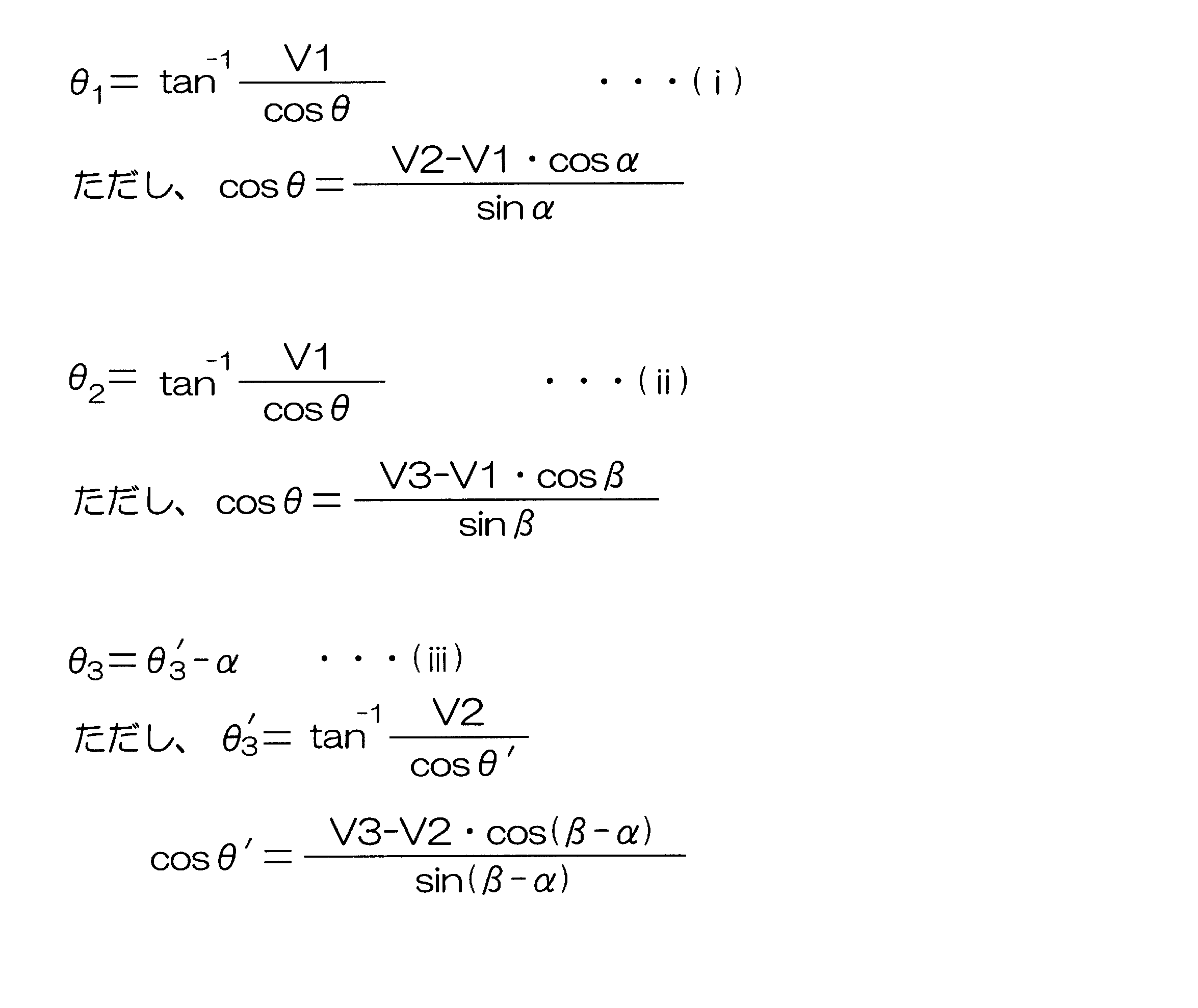
この構成では、式(i)により第1の回転角θ1が求められ、式(ii)により第2の回転角θ2が求められ、式(iii)により、第3の回転角θ3が求められる。このようにして求められた、第1、第2および第3の回転角に基づいて、最終的な回転角が演算される。
この発明の第2の回転角検出装置は、回転体(1)の回転に応じて、互いに位相差を有する第1および第2の正弦波信号をそれぞれ出力する第1および第2のセンサ(11,12)を含み、これらのセンサの出力信号に基づいて前記回転体の回転角を検出する回転角検出装置(40)であって、前記第1の正弦波信号と前記第2の正弦波信号とに基づいて、所定の第1の演算式を用いて、前記回転体の回転角に相当する第1の回転角を演算する第1回転角演算手段(41)と、前記第1の正弦波信号と前記第2の正弦波信号とに基づいて、前記第1の演算式とは異なる所定の第2の演算式を用いて、前記回転体の回転角に相当する第2の回転角を演算する第2回転角演算手段(42)と、前記第1の回転角および前記第2の回転角を用いて最終的な回転角を演算する最終回転角演算手段(43)とを含む。
この発明の第2の回転角検出装置は、回転体(1)の回転に応じて、互いに位相差を有する第1および第2の正弦波信号をそれぞれ出力する第1および第2のセンサ(11,12)を含み、これらのセンサの出力信号に基づいて前記回転体の回転角を検出する回転角検出装置(40)であって、前記第1の正弦波信号と前記第2の正弦波信号とに基づいて、所定の第1の演算式を用いて、前記回転体の回転角に相当する第1の回転角を演算する第1回転角演算手段(41)と、前記第1の正弦波信号と前記第2の正弦波信号とに基づいて、前記第1の演算式とは異なる所定の第2の演算式を用いて、前記回転体の回転角に相当する第2の回転角を演算する第2回転角演算手段(42)と、前記第1の回転角および前記第2の回転角を用いて最終的な回転角を演算する最終回転角演算手段(43)とを含む。
この構成では、第1の正弦波信号と第2の正弦波信号とに基づいて、所定の第1の演算式を用いて、回転体の回転角に相当する第1の回転角が演算される。また、第1の正弦波信号と第2の正弦波信号とに基づいて、第1の演算式とは異なる所定の第2の演算式を用いて、回転体の回転角に相当する第2の回転角が演算される。そして、第1の回転角および第2の回転角を用いて、最終的な回転角が演算される。
互いに位相差を有する2つの正弦波信号から演算される回転角には、その演算に用いられる演算式に起因して、演算誤差が大きくなる回転角の範囲が存在する。上記構成では、第1の回転角と第2の回転角とでは、その演算に用いられる演算式が異なるため、演算誤差が大きくなる回転角の範囲が異なる。上記構成によれば、第1の回転角および第2の回転角を用いて、演算誤差の少ない回転角を演算することが可能となる。このため、回転角の検出精度を高めることができる。
この発明の一実施形態では、前記最終回転角演算手段は、前記回転体の回転角を推定する回転角推定手段(51)と、前記回転角推定手段によって推定された回転角推定値に応じて、前記第1の回転角および前記第2の回転角を用いて、最終的な回転角を演算する演算手段(52)とを含む。
前記演算手段(52)は、前記回転角推定手段によって推定された回転角推定値に応じて、前記第1の回転角および前記第2の回転角のうち、演算誤差が小さい方の回転角を、最終的な回転角として選択するものであってもよい。あるいは、前記演算手段は、前記第1の回転角および前記第2の回転角それぞれに、前記回転角推定手段によって推定された回転角推定値に応じた重み付けをして加算することにより、最終的な回転角を求めるものであってもよい。
前記演算手段(52)は、前記回転角推定手段によって推定された回転角推定値に応じて、前記第1の回転角および前記第2の回転角のうち、演算誤差が小さい方の回転角を、最終的な回転角として選択するものであってもよい。あるいは、前記演算手段は、前記第1の回転角および前記第2の回転角それぞれに、前記回転角推定手段によって推定された回転角推定値に応じた重み付けをして加算することにより、最終的な回転角を求めるものであってもよい。
前記回転角推定手段(51)は、前記第1の回転角と前記第2の回転角との平均値を、前記回転角推定値として演算するものであってもよい。また、前記回転角推定値としては、たとえば、第1の回転角、第2の回転角などを用いることができる。また、第1の回転角と第2の回転角のいずれかが最終的な回転角として最初に選択された後においては、現在選択されている第1または第2の回転角を回転角推定値として用いるようにしてもよい。さらに、最終的な回転角が最初に演算された後においては、前回演算された最終的な回転角を、今回の回転角推定値として用いるようにしてもよい。
本発明における上述の、またはさらに他の目的、特徴および効果は、添付図面を参照して次に述べる実施形態の説明により明らかにされる。
以下では、この発明をブラシレスモータのロータの回転角を検出するための回転角検出装置に適用した場合の実施形態について、添付図面を参照して詳細に説明する。
図1は、この発明の第1の実施形態に係る回転角検出装置の構成を示す模式図である。
この回転角検出装置は、たとえば、電動パワーステアリング装置のブラシレスモータのロータの回転角を検出するために用いることができる。回転角検出装置は、たとえば、ブラシレスモータの回転に応じて回転する検出用ロータ1(以下、「ロータ1」という)を有している。ロータ1は、2つの磁極N,Sを有する磁石を含んでいる。以上の点は、後述する第2および第3の実施形態に係る回転角検出装置も同様である。
図1は、この発明の第1の実施形態に係る回転角検出装置の構成を示す模式図である。
この回転角検出装置は、たとえば、電動パワーステアリング装置のブラシレスモータのロータの回転角を検出するために用いることができる。回転角検出装置は、たとえば、ブラシレスモータの回転に応じて回転する検出用ロータ1(以下、「ロータ1」という)を有している。ロータ1は、2つの磁極N,Sを有する磁石を含んでいる。以上の点は、後述する第2および第3の実施形態に係る回転角検出装置も同様である。
ロータ1の周囲には、3つの磁気センサ11,12,13が、ロータ1の周方向に間隔をおいて配置されている。これら3つの磁気センサ11,12,13を、それぞれ第1の磁気センサ11、第2の磁気センサ12および第3の磁気センサ13という場合がある。磁気センサとしては、たとえば、ホール素子、磁気抵抗素子(MR素子)等、磁界の作用により電気的特性が変化する特性を有する素子を備えたものを用いることができる。
第1の磁気センサ11と第2の磁気センサ12とは、ロータ1の回転中心軸を中心として、αの角度間隔をおいて配置されている。第1の磁気センサ11と第3の磁気センサ13とは、ロータ1の回転中心軸を中心として、αより大きなβの角度間隔をおいて配置されている。この実施形態では、αは90°に設定され、βは180°に設定されている。したがって、この実施形態では、第2の磁気センサ12と第3の磁気センサ13との間の角度間隔は、90°となる。
図1に矢印で示す方向をロータ1の正方向の回転方向とする。そして、ロータ1が正方向に回転されるとロータ1の回転角が大きくなり、ロータ1が逆方向に回転されると、ロータ1の回転角が小さくなるものとする。ロータ1の回転角θに対して、第1の磁気センサ11からV1=A1・sinθの出力信号V1が出力されるとすると、第2の磁気センサ12からは、V2=A2・sin(θ+α)=A2・sin(θ+90°)の出力信号V2が出力され、第3の磁気センサ13からは、V3=A3・sin(θ+β)=A3・sin(θ+180°)の出力信号V3が出力される。A1,A2,A3は、それぞれ振幅を表している。
これらの振幅A1,A2,A3が互いに等しい値Aであるとみなすか、あるいは各振幅が所定の規定値Aとなるように各信号V1,V2,V3を正規化したとすると、各信号V1,V2,V3は、それぞれ、A・sinθ,A・sin(θ+α)およびA・sin(θ+β)と表される。ここで、A=1とすると、各信号V1,V2,V3は、それぞれ、sinθ, sin(θ+α)およびsin(θ+β)と表される。そこで、以下の説明においては、説明を簡単にするために、各磁気センサ11,12,13の出力信号V1,V2,V3を、それぞれV1=sinθ,V2=sin(θ+α)=sin(θ+90°)およびV3=sin(θ+β)=sin(θ+180°)と表すことにする。
各磁気センサ11,12,13の出力信号V1,V2,V3は、回転角演算装置20に入力される。回転角演算装置20は、各磁気センサ11,12,13の出力信号V1,V2,V3に基づいて、ロータ1の回転角θを演算する。回転角演算装置20は、たとえば、マイクロコンピュータから構成され、CPU(中央演算処理装置)およびメモリ(ROM,RAM等)を含んでいる。回転角演算装置20は、ROMに格納された所定のプログラムをCPUが実行することにより、複数の機能処理部として機能する。この複数の機能処理部は、第1の回転角演算部(第1回転角演算手段)21、第2の回転角演算部(第2回転角演算手段)22および回転角選択部(最終回転角演算手段)23を含む。
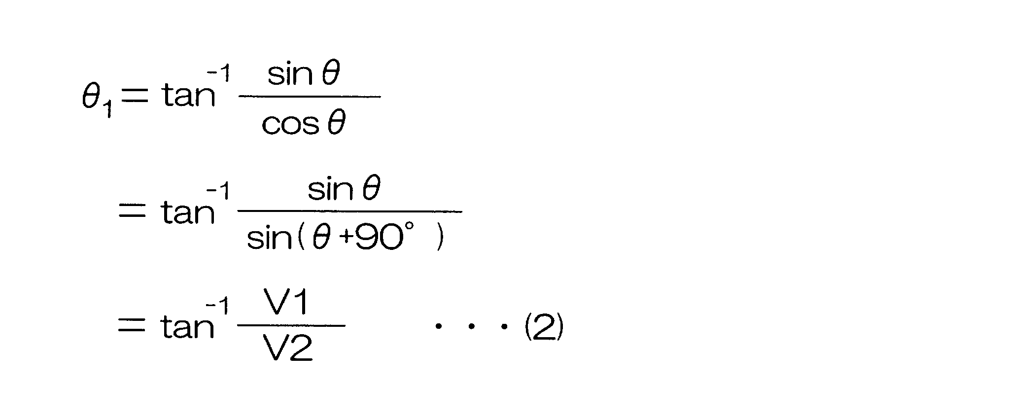
第1の回転角演算部21は、第1の磁気センサ11の出力信号V1と、第2の磁気センサ12の出力信号V2とに基づいて、ロータ1の回転角に相当する第1の回転角θ1を演算する。この実施形態では、V1=sinθ,V2=sin(θ+90°)=cosθである。また、tanθは、tanθ=sinθ/cosθと表すことができる。そこで、第1の回転角演算部21は、次式(2)に基づいて、第1の回転角θ1を演算する。
第2の回転角演算部22は、第2の磁気センサ12の出力信号V2と、第3の磁気センサ13の出力信号V3とに基づいて、ロータ1の回転角に相当する第2の回転角θ2を演算する。この実施形態では、V2=sin(θ+90°),V3=sin(θ+180°)=cos(θ+90°)である。また、tan(θ+90°)は、tan(θ+90°)=sin(θ+90°)/cos(θ+90°)と表すことができる。そこで、第2の回転角演算部22は、次式(3)に基づいて、第2の回転角θ2を演算する。

回転角選択部23は、ロータ1の回転角推定値に応じて、第1の回転角θ1および第2の回転角θ2のうちのいずれか一方を、最終的な回転角θとして選択する。回転角選択部23による回転角選択の考え方について説明する。
図2は、ロータ1の回転角θに対する、磁気センサ11,12の出力信号V1(=sinθ),V2(=sin(θ+90°))および前記式(2)の右辺におけるsinθ/sin(θ+90°)の変化を示している。sinθ/sin(θ+90°)の分母のsin(θ+90°)の絶対値が小さい場合には、tan-1(sinθ/sin(θ+90°))の演算誤差が大きくなり、第1の回転角θ1の演算誤差が大きくなる。したがって、図2に斜線部分で示すように、ロータ1の回転角θが、90°付近の範囲(たとえば、90°±22.5°の範囲)および270°付近の範囲(たとえば、270°±22.5°の範囲)では、sin(θ+90°)の絶対値が小さくなるので、第1の回転角θ1の演算誤差が大きくなる。
図2は、ロータ1の回転角θに対する、磁気センサ11,12の出力信号V1(=sinθ),V2(=sin(θ+90°))および前記式(2)の右辺におけるsinθ/sin(θ+90°)の変化を示している。sinθ/sin(θ+90°)の分母のsin(θ+90°)の絶対値が小さい場合には、tan-1(sinθ/sin(θ+90°))の演算誤差が大きくなり、第1の回転角θ1の演算誤差が大きくなる。したがって、図2に斜線部分で示すように、ロータ1の回転角θが、90°付近の範囲(たとえば、90°±22.5°の範囲)および270°付近の範囲(たとえば、270°±22.5°の範囲)では、sin(θ+90°)の絶対値が小さくなるので、第1の回転角θ1の演算誤差が大きくなる。
図2において、sinθ/sin(θ+90°)を表す曲線のうち、鎖線の楕円で囲まれた部分は、sin(θ+90°)の絶対値が大きくなるために、tan-1(sinθ/sin(θ+90°))の演算誤差が小さくなる部分(演算精度が高くなる部分)を示している。
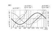
図3は、ロータ1の回転角θに対する、磁気センサ12,13の出力信号V2(=sin(θ+90°),V3(=sin(θ+180°))および前記式(3)の右辺におけるsin(θ+90°)/sin(θ+180°)の変化を示している。sin(θ+90°)/sin(θ+180°)の分母のsin(θ+180°)の絶対値が小さい場合には、tan-1{(sin(θ+90°)/sin(θ+180°)}の演算誤差が大きくなり、第2の回転角θ2の演算誤差が大きくなる。したがって、図3に斜線部分で示すように、ロータ1の回転角θが、0°付近の範囲(たとえば、0°~22.5°の範囲)、180°付近の範囲(たとえば、180°±22.5°の範囲)および360°付近の範囲(たとえば、337.5~360°の範囲)では、sin(θ+180°)の絶対値が小さくなるので、第2の回転角θ2の演算誤差が大きくなる。
図3は、ロータ1の回転角θに対する、磁気センサ12,13の出力信号V2(=sin(θ+90°),V3(=sin(θ+180°))および前記式(3)の右辺におけるsin(θ+90°)/sin(θ+180°)の変化を示している。sin(θ+90°)/sin(θ+180°)の分母のsin(θ+180°)の絶対値が小さい場合には、tan-1{(sin(θ+90°)/sin(θ+180°)}の演算誤差が大きくなり、第2の回転角θ2の演算誤差が大きくなる。したがって、図3に斜線部分で示すように、ロータ1の回転角θが、0°付近の範囲(たとえば、0°~22.5°の範囲)、180°付近の範囲(たとえば、180°±22.5°の範囲)および360°付近の範囲(たとえば、337.5~360°の範囲)では、sin(θ+180°)の絶対値が小さくなるので、第2の回転角θ2の演算誤差が大きくなる。
図3において、sin(θ+90°)/sin(θ+180°)を表す曲線のうち、鎖線の楕円で囲まれた部分は、sin(θ+180°)の絶対値が大きくなるために、tan-1sin(θ+90°)/sin(θ+180°)の演算誤差が小さくなる部分(演算精度が高くなる部分)を示している。
図2および図3で説明したように、第1の回転角θ1と第2の回転角θ2とでは、演算誤差が大きくなる角度範囲が異なる。そこで、回転角選択部23は、たとえば、第1の回転角θ1と第2の回転角θ2とからロータ1の回転角を推定し、推定された回転角(回転角推定値)に応じて、第1の回転角θ1および第2の回転角θ2のうちから、演算誤差が小さい(演算精度が高い)と推定される方を、最終的な回転角θとして選択する。
図2および図3で説明したように、第1の回転角θ1と第2の回転角θ2とでは、演算誤差が大きくなる角度範囲が異なる。そこで、回転角選択部23は、たとえば、第1の回転角θ1と第2の回転角θ2とからロータ1の回転角を推定し、推定された回転角(回転角推定値)に応じて、第1の回転角θ1および第2の回転角θ2のうちから、演算誤差が小さい(演算精度が高い)と推定される方を、最終的な回転角θとして選択する。
具体的には、回転角選択部23は、回転角推定部31と、選択部32とを備えている。回転角推定部31は、たとえば、次式(4)に基づいて、第1の回転角θ1と第2の回転角θ2との平均を演算することにより、回転角推定値θEを求める。
θE=(θ1+θ2)/2 …(4)
選択部32は、回転角推定部31によって得られた回転角推定値θEを用い、次式(5)に示す条件式にしたがって、第1の回転角θ1および第2の回転角θ2のうちの一方を、最終的な回転角θとして選択する。
θE=(θ1+θ2)/2 …(4)
選択部32は、回転角推定部31によって得られた回転角推定値θEを用い、次式(5)に示す条件式にしたがって、第1の回転角θ1および第2の回転角θ2のうちの一方を、最終的な回転角θとして選択する。
If 0°≦θE<45° then θ=θ1
If 45°≦θE<135° then θ=θ2
If 135°≦θE<225° then θ=θ1
If 225°≦θE<315° then θ=θ2
If 315°≦θE<360° then θ=θ1 …(5)
図4は、回転角推定値θEに対するsinθ/sin(θ+90°)の変化と、回転角推定値θEに対するsin(θ+90°)/sin(θ+180°)の変化とを示している。前述したように、tan-1{(sinθ°)/sin(θ+90°)}は、第1の回転角θ1を演算するために用いられ、tan-1{(sin(θ+90°)/sin(θ+180°)}は、第2の回転角θ2を演算するために用いられる。
If 45°≦θE<135° then θ=θ2
If 135°≦θE<225° then θ=θ1
If 225°≦θE<315° then θ=θ2
If 315°≦θE<360° then θ=θ1 …(5)
図4は、回転角推定値θEに対するsinθ/sin(θ+90°)の変化と、回転角推定値θEに対するsin(θ+90°)/sin(θ+180°)の変化とを示している。前述したように、tan-1{(sinθ°)/sin(θ+90°)}は、第1の回転角θ1を演算するために用いられ、tan-1{(sin(θ+90°)/sin(θ+180°)}は、第2の回転角θ2を演算するために用いられる。
図4においては、sinθ/sin(θ+90°)を表す曲線のうち、演算精度が高い部分(図2において楕円で囲まれた部分に相当する)が、その他の部分より太い線で示されている。同様に、sin(θ+90°)/sin(θ+180°)を表す曲線のうち、演算精度が高い部分(図3において楕円で囲まれた部分に相当する)が、その他の部分より太い線で示されている。前記式(5)で示された条件式にしたがって、第1の回転角θ1および第2の回転角θ2のうちから最終的な回転角θを選択する場合には、回転角推定値θEに対応する前記曲線の太線部分(演算精度の高い部分)を用いて演算された回転角が、最終的な回転角θとして選択されることになる。
図5は、回転角演算装置20によって実行される回転角演算処理の手順を示すフローチャートである。
回転角演算処理は、所定の演算周期毎に繰り返し行なわれる。まず、回転角演算装置20は、各磁気センサ11,12,13の出力信号V1(=sinθ),V2(=sin(θ+90°)),V3(=sin(θ+180°))を取り込む(ステップS1)。そして、回転角演算装置20の第1の回転角演算部21は、ステップS1で取り込まれた出力信号V1,V2を用い、前記式(2)に基づいて、第1の回転角θ1を演算する(ステップS2)。
回転角演算処理は、所定の演算周期毎に繰り返し行なわれる。まず、回転角演算装置20は、各磁気センサ11,12,13の出力信号V1(=sinθ),V2(=sin(θ+90°)),V3(=sin(θ+180°))を取り込む(ステップS1)。そして、回転角演算装置20の第1の回転角演算部21は、ステップS1で取り込まれた出力信号V1,V2を用い、前記式(2)に基づいて、第1の回転角θ1を演算する(ステップS2)。
また、回転角演算装置20の第2の回転角演算部22は、ステップS1で取り込まれた出力信号V2,V3を用い、前記式(3)に基づいて、第2の回転角θ2を演算する(ステップS3)。
また、回転角演算装置20の回転角選択部23は、第1の回転角θ1と第2の回転角θ2とに基づいて回転角推定値θEを演算する(ステップS4)。回転角選択部23は、たとえば、前記式(4)に基づいて、第1の回転角θ1と第2の回転角θ2の平均値を、回転角推定値θEとして求める。そして、回転角選択部23は、回転角推定値θEを用い、前記式(5)の条件式にしたがって、第1の回転角θ1および第2の回転角θ2のうちの一方を、最終的な回転角θとして選択する。(ステップS5)。
また、回転角演算装置20の回転角選択部23は、第1の回転角θ1と第2の回転角θ2とに基づいて回転角推定値θEを演算する(ステップS4)。回転角選択部23は、たとえば、前記式(4)に基づいて、第1の回転角θ1と第2の回転角θ2の平均値を、回転角推定値θEとして求める。そして、回転角選択部23は、回転角推定値θEを用い、前記式(5)の条件式にしたがって、第1の回転角θ1および第2の回転角θ2のうちの一方を、最終的な回転角θとして選択する。(ステップS5)。
前記第1の実施形態では、第1の回転角θ1および第2の回転角θ2のうち、演算誤差が小さい方の回転角を、ロータ1の最終的な回転角θとして選択することができるようになる。このため、回転角θの検出精度を高めることができる。
上記第1の実施形態では、磁気センサが3個設けられているが、磁気センサを4個以上設け、隣り合う2つのセンサの組毎にロータ1の回転角θに相当する回転角を演算することにより、最終的な回転角θの候補となる回転角を3種類以上求め、それらの回転角候補のうちの1つを、最終的な回転角θとして選択するようにしてもよい。
上記第1の実施形態では、磁気センサが3個設けられているが、磁気センサを4個以上設け、隣り合う2つのセンサの組毎にロータ1の回転角θに相当する回転角を演算することにより、最終的な回転角θの候補となる回転角を3種類以上求め、それらの回転角候補のうちの1つを、最終的な回転角θとして選択するようにしてもよい。
図6は、この発明の第2の実施形態に係る回転角検出装置の構成を示す模式図である。
ロータ1の周囲には、2つの磁気センサ11,12が、ロータ1の周方向に間隔をおいて配置されている。これら2つの磁気センサ11,12を、それぞれ第1の磁気センサ11および第2の磁気センサ12という場合がある。第1の磁気センサ11と第2の磁気センサ12とは、ロータ1の回転中心軸を中心として、αの角度間隔をおいて配置されている。この実施形態では、αは90°に設定されている。
ロータ1の周囲には、2つの磁気センサ11,12が、ロータ1の周方向に間隔をおいて配置されている。これら2つの磁気センサ11,12を、それぞれ第1の磁気センサ11および第2の磁気センサ12という場合がある。第1の磁気センサ11と第2の磁気センサ12とは、ロータ1の回転中心軸を中心として、αの角度間隔をおいて配置されている。この実施形態では、αは90°に設定されている。
図6に矢印で示す方向をロータ1の正方向の回転方向とする。また、第1の実施形態と同様に、各磁気センサ11,12の出力信号を、その振幅が1であるものとして簡易的に表すことにする。ロータ1の回転角θに対して、第1の磁気センサ11からV1=sinθの出力信号V1が出力されるとすると、第2の磁気センサ12からは、V2=sin(θ+α)=sin(θ+90°)の出力信号V2が出力される。
各磁気センサ11,12の出力信号V1,V2は、回転角演算装置40に入力される。回転角演算装置40は、各磁気センサ11,12の出力信号V1,V2に基づいて、ロータ1の回転角θを演算する。回転角演算装置40は、たとえば、マイクロコンピュータから構成され、CPU(中央演算処理装置)およびメモリ(ROM,RAM等)を含んでいる。回転角演算装置40は、ROMに格納された所定のプログラムをCPUが実行することにより、複数の機能処理部として機能する。この複数の機能処理部は、第1の回転角演算部(第1回転角演算手段)41、第2の回転角演算部(第2回転角演算手段)42および回転角選択部(最終回転角演算手段)43を含む。
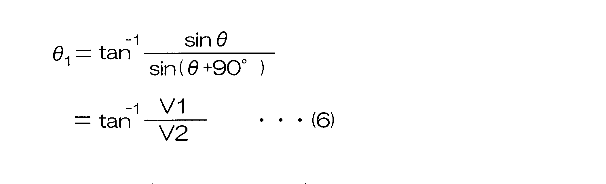
第1の回転角演算部41は、第1の磁気センサ11の出力信号V1と、第2の磁気センサ12の出力信号V2とに基づいて、次式(6)に示す演算式(以下、「第1演算式」という)を用いて、ロータ1の回転角に相当する第1の回転角θ1を演算する。この第1演算式は、第1の実施形態において説明した前記式(2)と同じである。
第2の回転角演算部42は、第1の磁気センサ11の出力信号V1と、第2の磁気センサ13の出力信号V3とに基づいて、次式(7)に示す演算式(以下、「第2演算式」という)を用いて、ロータ1の回転角に相当する第2の回転角θ2を演算する。

第2演算式の導き方について説明する。第1の出力信号V1は、sinθであるので、この信号V1を反転させることにより、V1’=-sinθで表される反転信号V1'を生成することができる。反転信号V1'は、V1'=-sinθ=sin(θ+180°)と表すことができるため、この反転信号V1’は、第1の実施形態における第3の出力信号V3と同様に、第1の出力信号V1に対し、位相が180°進んだ信号となる。言い換えれば、第2の出力信号V2(=sin(θ+90°))に対して、位相が90°進んだ信号となる。
したがって、この反転信号V1’は、V1’=-sinθ=sin(θ+180°)=cos(θ+90°)と表すことができる。tan(θ+90°)は、tan(θ+90°)=sin(θ+90°)/cos(θ+90°)と表すことができる。したがって、回転角θは、θ=tan-1{sin(θ+90°)/-sinθ}-90°=tan-1(V2/-V1)-90°と表すことができる。この回転角θを第2の回転角θ2とすることにより、前記式(7)を導くことがてきる。
回転角選択部43は、ロータ1の回転角推定値に応じて、第1の回転角θ1および第2の回転角θ2のうちのいずれか一方を、最終的な回転角θとして選択する。
第1の実施形態において、図2を用いて説明したように、第2の実施形態においても、ロータ1の回転角θが、90°付近の範囲(たとえば、90°±22.5°の範囲)および270°付近の範囲(たとえば、270°±22.5°の範囲)では、第1の回転角θ1の演算誤差が大きくなる。
第1の実施形態において、図2を用いて説明したように、第2の実施形態においても、ロータ1の回転角θが、90°付近の範囲(たとえば、90°±22.5°の範囲)および270°付近の範囲(たとえば、270°±22.5°の範囲)では、第1の回転角θ1の演算誤差が大きくなる。
第1の出力信号V1の反転信号V1’(=-sinθ)は、第1の実施形態の第3の出力信号V3=sin(θ+180°)と同様に、V1’=sin(θ+180°)と表すことができる。したがって、第2の実施形態における、V2=sin(θ+90°)、V1’=sin(-θ)およびsin(θ+90°)/-sinθを表す曲線は、それぞれ、図3におけるsin(θ+90°)、sin(θ+180°)およびsin(θ+90°)/sin(θ+180°)を表す曲線と同じになる。このため、第2の実施形態においても、図3に斜線部分で示すように、ロータ1の回転角θが、0°付近の範囲、180°付近の範囲および360°付近の範囲では、第2の回転角θ2の演算誤差が大きくなる。つまり、第2の実施形態においても、第1の回転角θ1と第2の回転角θ2とでは、演算誤差が大きくなるロータ角度範囲が異なる。
そこで、回転角選択部43は、たとえば、第1の回転角θ1と第2の回転角θ2とからロータ1の回転角を推定し、推定された回転角(回転角推定値)に応じて、第1の回転角θ1および第2の回転角θ2のうちから、演算誤差が小さい(演算精度の高い)と推定される方を、最終的な回転角θとして選択する。
具体的には、回転角選択部43は、回転角推定部51と、選択部52とを備えている。回転角推定部51は、たとえば、次式(8)に基づいて、第1の回転角θ1と第2の回転角θ2との平均を演算することにより、回転角推定値θEを求める。
具体的には、回転角選択部43は、回転角推定部51と、選択部52とを備えている。回転角推定部51は、たとえば、次式(8)に基づいて、第1の回転角θ1と第2の回転角θ2との平均を演算することにより、回転角推定値θEを求める。
θE=(θ1+θ2)/2 …(8)
選択部52は、回転角推定部51によって得られた回転角推定値θEを用い、次式(9)に示す条件式にしたがって、第1の回転角θ1および第2の回転角θ2のうちの一方を、最終的な回転角θとして選択する。なお、この条件式は、第1の実施形態における条件式(前記式(5)参照)と同じである。
選択部52は、回転角推定部51によって得られた回転角推定値θEを用い、次式(9)に示す条件式にしたがって、第1の回転角θ1および第2の回転角θ2のうちの一方を、最終的な回転角θとして選択する。なお、この条件式は、第1の実施形態における条件式(前記式(5)参照)と同じである。
If 0°≦θE<45° then θ=θ1
If 45°≦θE<135° then θ=θ2
If 135°≦θE<225° then θ=θ1
If 225°≦θE<315° then θ=θ2
If 315°≦θE<360° then θ=θ1 …(9)
図7は、回転角演算装置40によって実行される回転角演算処理の手順を示すフローチャートである。
If 45°≦θE<135° then θ=θ2
If 135°≦θE<225° then θ=θ1
If 225°≦θE<315° then θ=θ2
If 315°≦θE<360° then θ=θ1 …(9)
図7は、回転角演算装置40によって実行される回転角演算処理の手順を示すフローチャートである。
回転角演算処理は、所定の演算周期毎に繰り返し行なわれる。まず、回転角演算装置40は、各磁気センサ11,12の出力信号V1(=sinθ),V2(=sin(θ+90°))を取り込む(ステップS11)。そして、回転角演算装置40の第1の回転角演算部41は、ステップS11で取り込まれた出力信号V1,V2を用い、前記式(6)に示される第1演算式に基づいて、第1の回転角θ1を演算する(ステップS12)。
また、回転角演算装置40の第2の回転角演算部42は、ステップS11で取り込まれた出力信号V1,V2を用い、前記式(7)に示される第2演算式に基づいて、第2の回転角θ2を演算する(ステップS13)。
また、回転角演算装置40の回転角選択部43は、第1の回転角θ1と第2の回転角θ2とに基づいて回転角推定値θEを演算する(ステップS14)。回転角選択部43は、たとえば、前記式(8)に基づいて、第1の回転角θ1と第2の回転角θ2の平均値を、回転角推定値θEとして求める。そして、回転角選択部43は、回転角推定値θEを用い、前記式(9)の条件式にしたがって、第1の回転角θ1および第2の回転角θ2のうちの一方を、最終的な回転角θとして選択する。(ステップS15)。
また、回転角演算装置40の回転角選択部43は、第1の回転角θ1と第2の回転角θ2とに基づいて回転角推定値θEを演算する(ステップS14)。回転角選択部43は、たとえば、前記式(8)に基づいて、第1の回転角θ1と第2の回転角θ2の平均値を、回転角推定値θEとして求める。そして、回転角選択部43は、回転角推定値θEを用い、前記式(9)の条件式にしたがって、第1の回転角θ1および第2の回転角θ2のうちの一方を、最終的な回転角θとして選択する。(ステップS15)。
前記第2の実施形態においても、第1の回転角θ1および第2の回転角θ2のうち、演算誤差が小さい方の回転角を、ロータ1の最終的な回転角θとして選択することができるようになる。このため、回転角θの検出精度を高めることができる。第2の実施形態では、2個の磁気センサ11,12の出力信号V1,V2から、演算誤差が大きくなる角度範囲が互いに異なる、2種類の回転角θ1,θ2を演算することができるため、第1の実施形態に比べて、磁気センサの個数が少なくて済むという利点がある。
以上、この発明の第1および第2の実施形態について説明したが、この発明は、さらに他の形態で実施することもできる。たとえば、前述の第1および第2の実施形態では、回転角推定値θEに応じて、第1の回転角θ1および第2の回転角θ2のうちのいずれか一方が、最終的な回転角θとして選択されているが、第1の回転角θ1および第2の回転角θ2それぞれに回転角推定値θEに応じた重み付けをして加算することにより、最終的な回転角θを求めるようにしてもよい。
たとえば、前記式(5),(9)の条件式にしたがって回転角を選択する場合、第1の回転角θ1が選択される角度範囲と、第2の回転角θ2が選択される角度範囲は、図8(a)に示すようになる。そこで、図8(b)で示すように、回転角推定値θEが、第1の回転角θ1が選択される範囲の中央値である0°(360°)および180°に対しては、最終的な回転角θとして第1の回転角θ1を設定する。同様に、回転角推定値θEが、第2の回転角θ2が選択される範囲の中央値である90°および270°に対しては、最終的な回転角θとして第2の回転角θ2を設定する。
そして、0°<θE<90°の範囲、90°<θE<180°の範囲、180°<θE<270°の範囲および270°<θE<360°の範囲では、第1の回転角θ1および第2の回転角θ2にその範囲内の位置(角度:回転角推定値θE)に応じた重みw1,w2(w1+w2=1)を付けて加算した値を、最終的な回転角θ(=w1θ1+w2θ2)として設定する。具体的には、重みw1,w2は、次式(10)に基づいて求められる。

このように重みw1,w2を設定した場合には、前記各範囲のちょうど中間位置(θE=45°,135°,225°,315°)では、第1の回転角θ1および第2の回転角θ2に対する重みw1,w2は共に0.5となるので、その位置に対する最終的な回転角θは第1の回転角θ1および第2の平均値((θ1+θ2)/2)となる。
前記第1および第2の実施形態では、第1の回転角θ1と第2の回転角θ2との平均を演算することによって、回転角推定値θEを求めているが、第1の回転角θ1または第2の回転角θ2のいずれかを、回転角推定値θEとして用いるようにしてもよい。また、第1の回転角θ1と第2の回転角θ2のいずれかが最終的な回転角θとして最初に選択された後においては、現在選択されている第1または第2の回転角θ1,θ2を回転角推定値θEとして用いるようにしてもよい。さらに、最終的な回転角が最初に演算された後においては、前回演算された最終的な回転角θを、今回の回転角推定値θEとして用いるようにしてもよい。
前記第1および第2の実施形態では、第1の回転角θ1と第2の回転角θ2との平均を演算することによって、回転角推定値θEを求めているが、第1の回転角θ1または第2の回転角θ2のいずれかを、回転角推定値θEとして用いるようにしてもよい。また、第1の回転角θ1と第2の回転角θ2のいずれかが最終的な回転角θとして最初に選択された後においては、現在選択されている第1または第2の回転角θ1,θ2を回転角推定値θEとして用いるようにしてもよい。さらに、最終的な回転角が最初に演算された後においては、前回演算された最終的な回転角θを、今回の回転角推定値θEとして用いるようにしてもよい。
また、前記第1および第2の実施形態では、第1または第2の回転角θ1,θ2を、tan-1Xの演算を行なうことにより求めているが、tan-1Xの演算を行なわずに、たとえばマップにより、求めるようにしてもよい。
図9は、この発明の第3の実施形態に係る回転角検出装置の構成を示す模式図である。
ロータ1の周囲には、3つの磁気センサ61,62,63が、ロータ1の周方向に間隔をおいて配置されている。これら3つの磁気センサ61,62,63を、それぞれ第1の磁気センサ61、第2の磁気センサ62および第3の磁気センサ63という場合がある。第1の磁気センサ61と第2の磁気センサ62とは、ロータ1の回転中心軸を中心として、αの角度間隔をおいて配置されている。このαは、この例では、たとえば30°に設定されている。第1の磁気センサ61と第3の磁気センサ63とは、ロータ1の回転中心軸を中心として、αより大きなβの角度間隔をおいて配置されている。このβは、この例では、たとえば60°に設定されている。したがって、第2の磁気センサ62と第3の磁気センサ63との間の角度間隔は、(β-α)となる。この例では、(β-α)は、30°である。
図9に矢印で示す方向をロータ1の正方向の回転方向とする。また、第1の実施形態と同様に、各磁気センサ11,12の出力信号を、その振幅が1であるものとして簡易的に表すことにする。ロータ1の回転角θに対して、第1の磁気センサ61からV1=sinθの出力信号V1が出力されるとすると、第2の磁気センサ62からは、V2=sin(θ+α)の出力信号V2が出力され、第3の磁気センサ63からは、V3=sin(θ+β)の出力信号V3が出力される。
各磁気センサ61,62,63の出力信号V1,V2,V3は、回転角演算装置70に入力される。回転角演算装置70は、各磁気センサ61,62,63の出力信号V1,V2,V3に基づいて、ロータ1の回転角θを演算する。回転角演算装置70は、たとえば、マイクロコンピュータから構成され、CPU(中央演算処理装置)およびメモリ(ROM,RAM等)を含んでいる。回転角演算装置70は、ROMに格納された所定のプログラムをCPUが実行することにより、複数の機能処理部として機能する。この複数の機能処理部は、第1の回転角演算部(第1回転角演算手段)71、第2の回転角演算部(第2回転角演算手段)72、第3の回転角演算部(第3回転角演算手段)73および最終回転角演算部(最終回転角演算手段)74を含む。
第1の回転角演算部71は、第1の磁気センサ61の出力信号V1と、第2の磁気センサ62の出力信号V2とに基づいて、ロータ1の回転角に相当する第1の回転角θ1を演算する。第2の回転角演算部72は、第1の磁気センサ61の出力信号V1と、第3の磁気センサ63の出力信号V3とに基づいて、ロータ1の回転角に相当する第2の回転角θ2を演算する。第3の回転角演算部73は、第2の磁気センサ62の出力信号V2と、第3の磁気センサ63の出力信号V3とに基づいて、ロータ1の回転角に相当する第3の回転角θ3を演算する。
最終回転角演算部74は、第1,第2および第3の回転角演算部71,72,73によってそれぞれ演算された第1,第2および第3の回転角θ1,θ2,θ3に基づいて、最終的な回転角θを演算する。
図10は、回転角演算装置70のさらに詳細な構成を示す機能ブロック図である。
第1の回転角演算部71は、信号生成部81と、角度演算部82とを含んでいる。信号生成部81は、第1の出力信号V1(=sinθ)と第2の出力信号V2(=sin(θ+α))とから、第1の出力信号V1に対する位相差が90°となる信号V12(=sin(θ+90°)=cosθ)を生成する。具体的には、信号生成部81は、次式(11)に基づいて、信号V12を生成する。
図10は、回転角演算装置70のさらに詳細な構成を示す機能ブロック図である。
第1の回転角演算部71は、信号生成部81と、角度演算部82とを含んでいる。信号生成部81は、第1の出力信号V1(=sinθ)と第2の出力信号V2(=sin(θ+α))とから、第1の出力信号V1に対する位相差が90°となる信号V12(=sin(θ+90°)=cosθ)を生成する。具体的には、信号生成部81は、次式(11)に基づいて、信号V12を生成する。

つまり、信号生成部81は、第1の出力信号V1(=sinθ)と、第2の出力信号V2(=sin(θ+α))と、cosαと,sinαとから、信号V12(=cosθ)を生成する。cosα,sinαは、予めメモリに格納されている。なお、前記式(11)は、sin(θ+α)を三角関数の加法定理により展開した式に基づいて、導出することができる。
角度演算部82は、信号生成部81によって生成された信号V12(=cosθ)と第1の出力信号V1(=sinθ)とを用い、次式(12)に基づいて、第1の回転角θ1を演算する。
角度演算部82は、信号生成部81によって生成された信号V12(=cosθ)と第1の出力信号V1(=sinθ)とを用い、次式(12)に基づいて、第1の回転角θ1を演算する。

第2の回転角演算部72は、信号生成部91と、角度演算部92とを含んでいる。信号生成部91は、第1の出力信号V1(=sinθ)と第3の出力信号V3(=sin(θ+β))とから、第1の出力信号V1に対する位相差が90°となる信号V13(=sin(θ+90°)=cosθ)を生成する。具体的には、信号生成部91は、次式(13)に基づいて、信号V13を生成する。
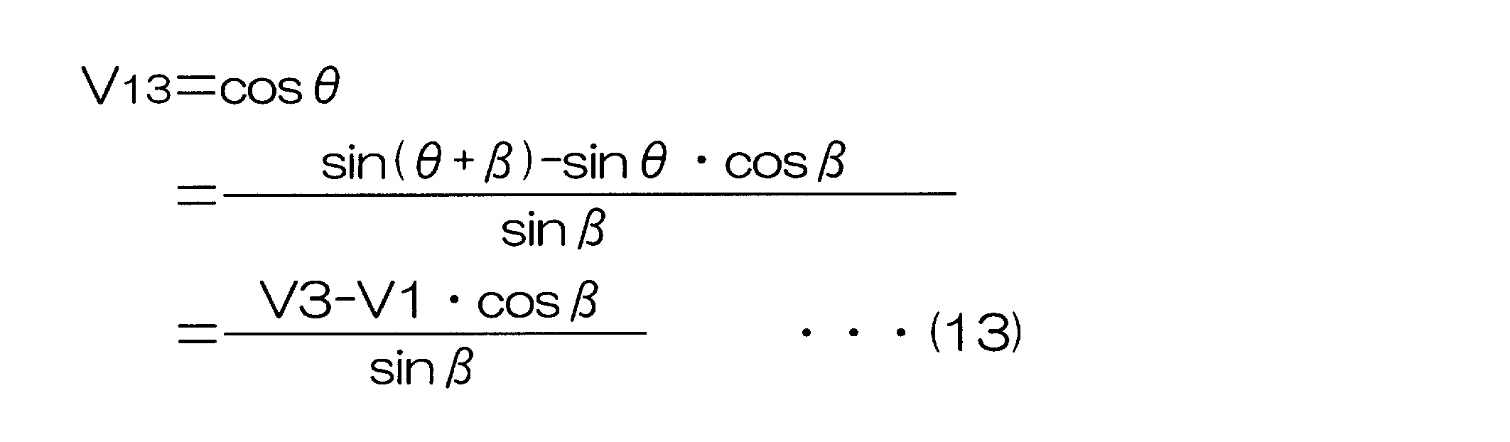
つまり、信号生成部91は、第1の出力信号V1(=sinθ)と、第3の出力信号V3(=sin(θ+β))と、cosβと,sinβとから、信号V13(=cosθ)を生成する。cosβ,sinβは、予めメモリに格納されている。なお、前記式(13)は、前記式(11)と同様に、sin(θ+β)を三角関数の加法定理により展開した式に基づいて、導出することができる。
角度演算部92は、信号生成部91によって生成された信号V13(=cosθ2)と第1の出力信号V1(=sinθ)とを用い、次式(14)に基づいて、第2の回転角θ2を演算する。

第3の回転角演算部73による第3の回転角θ3の演算方法の考え方について説明する。第3の回転角演算部73は、まず、第2の出力信号V2と第3の出力信号V3とに基づいて、ロータ1の回転角θに対してαだけ進んだ回転角θ3’(=θ+α)を演算する。そして、得られた回転角θ3’からαを減算することにより、第3の回転角θ3を演算する。
第3の回転角演算部73は、信号生成部101と、角度演算部102と、角度演算部103とを含んでいる。信号生成部101は、第2の出力信号V2(=sin(θ+α))と第3の出力信号V3(=sin(θ+β))とから、第2の出力信号V2に対する位相差が90°となる信号V23(=sin(θ+α+90°))を生成する。
θ’=θ+αとして、出力信号V2を正弦波信号sinθ’で表し、出力信号V3を、この正弦波信号sinθ’に対して位相差が(β-α)進んだ正弦波信号sin(θ’+(β-α))で表すと、前記第1の回転角演算部71と同様な方法により、正弦波信号sinθ’に対して位相差が90°となる信号V23(=sin(θ’+90°)=cosθ’)を求めることができる。
θ’=θ+αとして、出力信号V2を正弦波信号sinθ’で表し、出力信号V3を、この正弦波信号sinθ’に対して位相差が(β-α)進んだ正弦波信号sin(θ’+(β-α))で表すと、前記第1の回転角演算部71と同様な方法により、正弦波信号sinθ’に対して位相差が90°となる信号V23(=sin(θ’+90°)=cosθ’)を求めることができる。
具体的には、信号生成部101は、次式(15)に基づいて、信号V23を生成する。
つまり、信号生成部101は、第2の出力信号V2(=sin(θ+α))と、第3の出力信号V3(=sin(θ+β))と、cos(βーα)と、sin(βーα)とから、信号V23(=cosθ’)を生成する。cos(βーα)、sin(βーα)は、予めメモリに格納されている。
角度演算部102は、信号生成部101によって生成された信号V23(=cosθ’)と第2の出力信号V2(=sinθ’=sin(θ+α))とを用い、次式(16)に基づいて、回転角θ3’を演算する。
角度演算部102は、信号生成部101によって生成された信号V23(=cosθ’)と第2の出力信号V2(=sinθ’=sin(θ+α))とを用い、次式(16)に基づいて、回転角θ3’を演算する。

角度演算部103は、次式(17)に基づいて、第3の回転角θ3を演算する。
θ3=θ3’-α …(17)
なお、αは予めメモリに格納されている。
最終回転角演算部74は、たとえば、次式(18)に基づいて、最終的な回転角θを演算する。つまり、最終回転角演算部74は、第1、第2および第3の回転角θ1,θ2,θ3の平均値を、最終的な回転角θとして演算する。
θ3=θ3’-α …(17)
なお、αは予めメモリに格納されている。
最終回転角演算部74は、たとえば、次式(18)に基づいて、最終的な回転角θを演算する。つまり、最終回転角演算部74は、第1、第2および第3の回転角θ1,θ2,θ3の平均値を、最終的な回転角θとして演算する。
θ=(θ1+θ2+θ3)/3 …(18)
図11は、回転角演算装置70によって実行される回転角演算処理の手順を示すフローチャートである。
回転角演算処理は、所定の演算周期毎に繰り返し行なわれる。まず、回転角演算装置70は、各磁気センサ61,62,63の出力信号V1(=sinθ),V2(=sin(θ+α)),V3(=sin(θ+β))を取り込む(ステップS21)。そして、回転角演算装置70の第1の回転角演算部71は、ステップS21で取り込まれた出力信号V1,V2と、メモリに格納されているsinαおよびcosαの値と、前記式(11),(12)とを用いて、第1の回転角θ1を演算する(ステップS22)。
図11は、回転角演算装置70によって実行される回転角演算処理の手順を示すフローチャートである。
回転角演算処理は、所定の演算周期毎に繰り返し行なわれる。まず、回転角演算装置70は、各磁気センサ61,62,63の出力信号V1(=sinθ),V2(=sin(θ+α)),V3(=sin(θ+β))を取り込む(ステップS21)。そして、回転角演算装置70の第1の回転角演算部71は、ステップS21で取り込まれた出力信号V1,V2と、メモリに格納されているsinαおよびcosαの値と、前記式(11),(12)とを用いて、第1の回転角θ1を演算する(ステップS22)。
また、回転角演算装置70の第2の回転角演算部72は、ステップS21で取り込まれた出力信号V1,V3と、メモリに格納されているsinβおよびcosβの値と、前記式(13),(14)とを用いて、第2の回転角θ2を演算する(ステップS23)。
また、回転角演算装置70の第3の回転角演算部73は、ステップS21で取り込まれた出力信号V2,V3と、メモリに格納されているα、sin(β-α)およびcos(β-α)の値と、前記式(15),(16),(17)とを用いて、第3の回転角θ3を演算する(ステップS24)。
また、回転角演算装置70の第3の回転角演算部73は、ステップS21で取り込まれた出力信号V2,V3と、メモリに格納されているα、sin(β-α)およびcos(β-α)の値と、前記式(15),(16),(17)とを用いて、第3の回転角θ3を演算する(ステップS24)。
そして、回転角演算装置70の最終回転角演算部74は、第1、第2および第3の回転角θ1,θ2,θ3に基づいて、最終的な回転角θを演算する(ステップS25)。たとえば、最終回転角演算部74は、前記式(18)に基づいて、第1、第2および第3の回転角θ1,θ2,θ3の平均値を、最終的な回転角θとして演算する。
前記第3の実施形態では、3つの回転角θ1,θ2,θ3の平均値が、最終的な回転角θとして求められている。このため、磁気センサの出力信号に含まれるノイズの影響による検出誤差を低減できる。また、最終的な回転角θは、同時刻に発生した出力信号V1,V2,V3から演算された3つの回転角θ1,θ2,θ3に基づいて演算されているので、時間方向に回転角を平均化することによって最終的な回転角を演算する場合に比べ、回転角検出に時間遅れが発生しない。このためロータ1の回転速度が大きい場合でも、高い応答性を実現できる。つまり、前記実施形態によれば、高い応答性を維持しつつ、ノイズの影響による検出誤差を低減できる。
前記第3の実施形態では、3つの回転角θ1,θ2,θ3の平均値が、最終的な回転角θとして求められている。このため、磁気センサの出力信号に含まれるノイズの影響による検出誤差を低減できる。また、最終的な回転角θは、同時刻に発生した出力信号V1,V2,V3から演算された3つの回転角θ1,θ2,θ3に基づいて演算されているので、時間方向に回転角を平均化することによって最終的な回転角を演算する場合に比べ、回転角検出に時間遅れが発生しない。このためロータ1の回転速度が大きい場合でも、高い応答性を実現できる。つまり、前記実施形態によれば、高い応答性を維持しつつ、ノイズの影響による検出誤差を低減できる。
また、前記第3の実施形態では、第1,第2および第3の回転角θ1,θ2,θ3を演算する場合に、同じ磁気センサの出力信号を複数の回転角演算のために共用している。具体的には、信号V1は、θ1,θ2の演算のために共用され、信号V2はθ1,θ3の演算のために共用され、信号V3はθ2,θ3の演算のために共用されている。このため、同じ磁気センサの出力信号を複数の回転角演算のために共用しない場合に比べて、磁気センサの個数が少なくて済むという利点がある。具体的には、前記のように3種類の回転角を演算する場合、同じ磁気センサの出力信号を複数の回転角演算のために共用しないとすると、6個の磁気センサが必要となるが、この実施形態では3個で済む。
また、前記第3の実施形態では、最終回転角演算部74は、3つの回転角θ1,θ2,θ3の平均を最終的な回転角θとして演算しているが、3つの回転角θ1,θ2,θ3のうちの中央値を、最終的な回転角θとして演算するようにしてもよい。さらに、最終回転角演算部74は、3つの回転角θ1,θ2,θ3のうち、最も外れているものを除外し、他の2つの平均値を、最終的な回転角θとして演算するようにしてもよい。具体的には、3つの回転角θ1,θ2,θ3のうちの中央値と、他の2つの回転角のうち、中央値との差が小さいものとの平均値を、最終的な回転角θとする。
また、前記第3の実施形態では、磁気センサは3個設けられているが、磁気センサを4個以上設けるようにしてもよい。たとえば、磁気センサを4個設けた場合には、4個のセンサから2つのセンサをとる組み合わせは6通り存在するので、6種類の回転角を同時に検出することが可能となる。
また、この発明は、ブラシレスモータのロータ以外の回転体の回転角を検出する場合にも、適用することができる。
また、この発明は、ブラシレスモータのロータ以外の回転体の回転角を検出する場合にも、適用することができる。
本発明の実施形態について詳細に説明したが、これらは本発明の技術的内容を明らかにするために用いられた具体例に過ぎず、本発明はこれらの具体例に限定して解釈されるべきではなく、本発明の範囲は添付の請求の範囲によってのみ限定される。
この出願は、2009年8月26日に日本国特許庁に提出された特願2009-195190号および特願2009-195191号ならびに2010年7月23日に日本国特許庁に提出された特願2010-166122号に対応しており、これらの出願の全開示はここに引用により組み込まれるものとする。
この出願は、2009年8月26日に日本国特許庁に提出された特願2009-195190号および特願2009-195191号ならびに2010年7月23日に日本国特許庁に提出された特願2010-166122号に対応しており、これらの出願の全開示はここに引用により組み込まれるものとする。
1 ロータ
11,12,13,61,62,63 磁気センサ
11,12,13,61,62,63 磁気センサ
Claims (13)
- 回転体の回転に応じて、互いに位相差を有する第1、第2および第3の正弦波信号をそれぞれ出力する第1、第2および第3のセンサを含み、これらのセンサの出力信号に基づいて前記回転体の回転角を検出する回転角検出装置であって、
前記第1の正弦波信号と前記第2の正弦波信号との組合せ、前記第2の正弦波信号と前記第3の正弦波信号との組合せおよび前記第2の正弦波信号と前記第3の正弦波信号との組合せのうちの2以上の組合せにおける組合せ毎に、その組合せに含まれる2つの正弦波信号に基づいて前記回転体の回転角に相当する回転角を演算する回転角演算手段と、
前記回転角演算手段によって演算された複数の回転角を用いて、最終的な回転角を演算する最終回転角演算手段と、を含む回転角検出装置。 - 前記回転角演算手段は、
第1の正弦波信号と前記第2の正弦波信号とに基づいて、前記回転体の回転角に相当する第1の回転角を演算する第1回転角演算手段と、
前記第2の正弦波信号と前記第3の正弦波信号とに基づいて、前記回転体の回転角に相当する第2の回転角を演算する第2回転角演算手段とを含み、
前記最終回転角演算手段は、前記第1の回転角および前記第2の回転角を用いて、最終的な回転角を演算する、請求項1に記載の回転角検出装置。 - 前記最終回転角演算手段は、
前記回転体の回転角を推定する回転角推定手段と、
前記回転角推定手段によって推定された回転角推定値に応じて、前記第1の回転角および前記第2の回転角を用いて、最終的な回転角を演算する演算手段とを含む、請求項2に記載の回転角検出装置。 - 前記演算手段は、前記回転角推定手段によって推定された回転角推定値に応じて、前記第1の回転角および前記第2の回転角のうち、演算誤差が小さい方の回転角を、最終的な回転角として選択するものである、請求項3に記載の回転角検出装置。
- 前記演算手段は、前記第1の回転角および前記第2の回転角それぞれに、前記回転角推定手段によって推定された回転角推定値に応じた重み付けをして加算することにより、最終的な回転角を求めるものである、請求項3に記載の回転角検出装置。
- 前記回転角推定手段は、前記第1の回転角と前記第2の回転角との平均値を、前記回転角推定値として演算する請求項3~5のいずれか一項に記載の回転角検出装置。
- 前記回転角演算手段は、
前記第1の正弦波信号と前記第2の正弦波信号とに基づいて、前記回転体の回転角に相当する第1の回転角を演算する第1回転角演算手段と、
前記第1の正弦波信号と前記第3の正弦波信号とに基づいて、前記回転体の回転角に相当する第2の回転角を演算する第2回転角演算手段と、
前記第2の正弦波信号と前記第3の正弦波信号とに基づいて、前記回転体の回転角に相当する第3の回転角を演算する第3回転角演算手段とを含み、
前記最終回転角演算手段は、前記第1、第2および第3の回転角に基づいて、最終的な回転角を演算する、請求項1に記載の回転角検出装置。 - 前記第1のセンサは、前記回転体の回転角θに対して、V1=sinθで表される第1の正弦波信号V1を出力するものであり、
前記第2のセンサは、前記回転体の回転角θに対して、前記第1および第2の正弦波信号の位相差αを用いてV2=sin(θ+α)で表される第2の正弦波信号V2を出力するものであり、
前記第3のセンサは、前記回転体の回転角θに対して、前記第1および第3の正弦波信号の位相差βを用いてV3=sin(θ+β)で表される第3の正弦波信号V3を出力するものであり、
前記第1回転角演算手段は、次式(i)により、第1の回転角θ1を求めるものであり、
前記第2回転角演算手段は、次式(ii)により、第2の回転角θ2を求めるものであり、
前記第3回転角演算手段は、次式(iii)により、第3の回転角θ3を求めるものである、請求項7に記載の回転角検出装置。

- 回転体の回転に応じて、互いに位相差を有する第1および第2の正弦波信号をそれぞれ出力する第1および第2のセンサを含み、これらのセンサの出力信号に基づいて前記回転体の回転角を検出する回転角検出装置であって、
前記第1の正弦波信号と前記第2の正弦波信号とに基づいて、所定の第1の演算式を用いて、前記回転体の回転角に相当する第1の回転角を演算する第1回転角演算手段と、
前記第1の正弦波信号と前記第2の正弦波信号とに基づいて、前記第1の演算式とは異なる所定の第2の演算式を用いて、前記回転体の回転角に相当する第2の回転角を演算する第2回転角演算手段と、
前記第1の回転角および前記第2の回転角を用いて、最終的な回転角を演算する最終回転角演算手段と、
を含む回転角検出装置。 - 前記最終回転角演算手段は、
前記回転体の回転角を推定する回転角推定手段と、
前記回転角推定手段によって推定された回転角推定値に応じて、前記第1の回転角および前記第2の回転角を用いて、最終的な回転角を演算する演算手段とを含む、請求項9に記載の回転角検出装置。 - 前記演算手段は、前記回転角推定手段によって推定された回転角推定値に応じて、前記第1の回転角および前記第2の回転角のうち、演算誤差が小さい方の回転角を、最終的な回転角として選択するものである、請求項10に記載の回転角検出装置。
- 前記演算手段は、前記第1の回転角および前記第2の回転角それぞれに、前記回転角推定手段によって推定された回転角推定値に応じた重み付けをして加算することにより、最終的な回転角を求めるものである、請求項10に記載の回転角検出装置。
- 前記回転角推定手段は、前記第1の回転角と前記第2の回転角との平均値を、前記回転角推定値として演算する請求項10~12のいずれか一項に記載の回転角検出装置。
Priority Applications (3)
| Application Number | Priority Date | Filing Date | Title |
|---|---|---|---|
| EP10811781.3A EP2472233A4 (en) | 2009-08-26 | 2010-08-20 | DEVICE FOR DETECTING A ROTATION ANGLE |
| US13/389,977 US20120143563A1 (en) | 2009-08-26 | 2010-08-20 | Rotation angle detection device |
| CN201080037552XA CN102575946A (zh) | 2009-08-26 | 2010-08-20 | 旋转角检测装置 |
Applications Claiming Priority (6)
| Application Number | Priority Date | Filing Date | Title |
|---|---|---|---|
| JP2009-195190 | 2009-08-26 | ||
| JP2009195190 | 2009-08-26 | ||
| JP2009195191 | 2009-08-26 | ||
| JP2009-195191 | 2009-08-26 | ||
| JP2010166122A JP5557021B2 (ja) | 2009-08-26 | 2010-07-23 | 回転角検出装置 |
| JP2010-166122 | 2010-07-23 |
Publications (1)
| Publication Number | Publication Date |
|---|---|
| WO2011024731A1 true WO2011024731A1 (ja) | 2011-03-03 |
Family
ID=43627837
Family Applications (1)
| Application Number | Title | Priority Date | Filing Date |
|---|---|---|---|
| PCT/JP2010/064105 WO2011024731A1 (ja) | 2009-08-26 | 2010-08-20 | 回転角検出装置 |
Country Status (5)
| Country | Link |
|---|---|
| US (1) | US20120143563A1 (ja) |
| EP (1) | EP2472233A4 (ja) |
| JP (1) | JP5557021B2 (ja) |
| CN (1) | CN102575946A (ja) |
| WO (1) | WO2011024731A1 (ja) |
Cited By (2)
| Publication number | Priority date | Publication date | Assignee | Title |
|---|---|---|---|---|
| JP2015087113A (ja) * | 2013-10-28 | 2015-05-07 | 日本電産サンキョー株式会社 | 検出装置におけるデータ検出方法および検出装置 |
| CN111294457A (zh) * | 2018-12-10 | 2020-06-16 | 北京小米移动软件有限公司 | 滑盖式终端、滑盖状态检测方法、装置及存储介质 |
Families Citing this family (14)
| Publication number | Priority date | Publication date | Assignee | Title |
|---|---|---|---|---|
| JP5660381B2 (ja) * | 2011-03-09 | 2015-01-28 | 株式会社ジェイテクト | 回転角検出装置 |
| GB201110039D0 (en) * | 2011-06-15 | 2011-07-27 | Trw Ltd | Measurement of motor rotor position or speed |
| JP6086205B2 (ja) | 2012-12-12 | 2017-03-01 | 株式会社ジェイテクト | 位相差検出装置およびそれを備えた回転角検出装置 |
| JP6024971B2 (ja) | 2012-12-12 | 2016-11-16 | 株式会社ジェイテクト | 回転角検出装置 |
| JP6024969B2 (ja) | 2012-12-12 | 2016-11-16 | 株式会社ジェイテクト | 回転角検出装置およびそれを備えた電動パワーステアリング装置 |
| JP6024970B2 (ja) * | 2012-12-12 | 2016-11-16 | 株式会社ジェイテクト | 回転角検出装置およびそれを備えた電動パワーステアリング装置 |
| WO2016002732A1 (ja) * | 2014-06-30 | 2016-01-07 | パナソニックヘルスケアホールディングス株式会社 | 回転角度検出回路、回転角度検出方法、試料分析装置および試料分析装置のためのコンピュータプログラム |
| DE102015212812A1 (de) | 2015-07-08 | 2017-01-12 | Conti Temic Microelectronic Gmbh | Betrieb einer rotierenden elektrischen Maschine |
| JP2017138143A (ja) * | 2016-02-02 | 2017-08-10 | Tdk株式会社 | 変位検出装置および角速度検出装置 |
| CN107461288B (zh) * | 2016-06-03 | 2018-12-25 | 纳博特斯克有限公司 | 检测装置以及起动装置 |
| JP6758998B2 (ja) * | 2016-08-24 | 2020-09-23 | Ntn株式会社 | 電動モータ装置 |
| JP7035608B2 (ja) * | 2018-02-22 | 2022-03-15 | 株式会社デンソーウェーブ | ロボットのアーム回転軸速度検出装置 |
| JP7172797B2 (ja) * | 2019-03-28 | 2022-11-16 | 株式会社デンソー | 検出ユニット |
| JP7287375B2 (ja) * | 2020-10-23 | 2023-06-06 | Tdk株式会社 | 磁気センサアセンブリとこれを備えたカメラモジュール |
Citations (13)
| Publication number | Priority date | Publication date | Assignee | Title |
|---|---|---|---|---|
| JPH0555022A (ja) | 1991-08-26 | 1993-03-05 | Sankyo Seiki Mfg Co Ltd | 希土類ボンド磁石 |
| JPH09508214A (ja) | 1994-11-22 | 1997-08-19 | ローベルト ボツシユ ゲゼルシヤフト ミツト ベシユレンクテル ハフツング | 回転可能部材の無接触形回転角検出装置 |
| JP2001324321A (ja) | 2000-03-07 | 2001-11-22 | Koyo Seiko Co Ltd | 回転角度検出装置、トルク検出装置及び舵取装置 |
| JP2002213944A (ja) | 2001-01-18 | 2002-07-31 | Niles Parts Co Ltd | 回転角測定装置 |
| JP2003240598A (ja) * | 2002-02-13 | 2003-08-27 | Asahi Kasei Corp | デジタル角度測定システム |
| JP2004156961A (ja) | 2002-11-05 | 2004-06-03 | Koyo Seiko Co Ltd | 回転角検出装置及びトルク検出装置 |
| JP2004264167A (ja) * | 2003-03-03 | 2004-09-24 | Midori Sokki:Kk | 回転角度センサ |
| JP2007155618A (ja) * | 2005-12-07 | 2007-06-21 | Denso Corp | 回転角度検出装置 |
| JP2008128961A (ja) * | 2006-11-24 | 2008-06-05 | Alps Electric Co Ltd | 絶対角検出装置 |
| JP2008241411A (ja) | 2007-03-27 | 2008-10-09 | Jtekt Corp | 舵角検出装置 |
| JP2009195190A (ja) | 2008-02-22 | 2009-09-03 | Panasonic Electric Works Co Ltd | 害虫防除装置 |
| JP2009195191A (ja) | 2008-02-22 | 2009-09-03 | Hayashi Bussan Hatsumei Kenkyusho:Kk | コケもしくは匍匐植物の育成具 |
| JP2010166122A (ja) | 2009-01-13 | 2010-07-29 | Olympus Corp | 撮像装置及び画像処理方法 |
Family Cites Families (9)
| Publication number | Priority date | Publication date | Assignee | Title |
|---|---|---|---|---|
| DE19941101B4 (de) * | 1999-08-30 | 2008-01-17 | Delphi Technologies, Inc., Troy | Sensoranordnung |
| JP2001114116A (ja) * | 1999-10-19 | 2001-04-24 | Alps Electric Co Ltd | 回転角検出装置 |
| JP4763296B2 (ja) * | 2005-01-18 | 2011-08-31 | 古河電気工業株式会社 | 検知装置 |
| US7583080B2 (en) * | 2005-02-10 | 2009-09-01 | Panasonic Corporation | Rotation angle detection device and rotation angle correction method |
| WO2007004462A1 (ja) * | 2005-06-30 | 2007-01-11 | Murata Manufacturing Co., Ltd. | 検知装置及び回転角度センサ |
| JP4797721B2 (ja) * | 2005-10-20 | 2011-10-19 | 株式会社デンソー | 回転角度検出装置 |
| JP2008045881A (ja) * | 2006-08-10 | 2008-02-28 | Nsk Ltd | 回転角度位置検出装置 |
| KR100847491B1 (ko) * | 2007-03-20 | 2008-07-21 | 대성전기공업 주식회사 | 조향각센서 오류검출 장치 및 방법 |
| WO2008136054A1 (ja) * | 2007-04-24 | 2008-11-13 | Harmonic Drive Systems Inc. | 磁気式エンコーダおよび絶対回転位置検出方法 |
-
2010
- 2010-07-23 JP JP2010166122A patent/JP5557021B2/ja not_active Expired - Fee Related
- 2010-08-20 US US13/389,977 patent/US20120143563A1/en not_active Abandoned
- 2010-08-20 EP EP10811781.3A patent/EP2472233A4/en not_active Withdrawn
- 2010-08-20 CN CN201080037552XA patent/CN102575946A/zh active Pending
- 2010-08-20 WO PCT/JP2010/064105 patent/WO2011024731A1/ja active Application Filing
Patent Citations (13)
| Publication number | Priority date | Publication date | Assignee | Title |
|---|---|---|---|---|
| JPH0555022A (ja) | 1991-08-26 | 1993-03-05 | Sankyo Seiki Mfg Co Ltd | 希土類ボンド磁石 |
| JPH09508214A (ja) | 1994-11-22 | 1997-08-19 | ローベルト ボツシユ ゲゼルシヤフト ミツト ベシユレンクテル ハフツング | 回転可能部材の無接触形回転角検出装置 |
| JP2001324321A (ja) | 2000-03-07 | 2001-11-22 | Koyo Seiko Co Ltd | 回転角度検出装置、トルク検出装置及び舵取装置 |
| JP2002213944A (ja) | 2001-01-18 | 2002-07-31 | Niles Parts Co Ltd | 回転角測定装置 |
| JP2003240598A (ja) * | 2002-02-13 | 2003-08-27 | Asahi Kasei Corp | デジタル角度測定システム |
| JP2004156961A (ja) | 2002-11-05 | 2004-06-03 | Koyo Seiko Co Ltd | 回転角検出装置及びトルク検出装置 |
| JP2004264167A (ja) * | 2003-03-03 | 2004-09-24 | Midori Sokki:Kk | 回転角度センサ |
| JP2007155618A (ja) * | 2005-12-07 | 2007-06-21 | Denso Corp | 回転角度検出装置 |
| JP2008128961A (ja) * | 2006-11-24 | 2008-06-05 | Alps Electric Co Ltd | 絶対角検出装置 |
| JP2008241411A (ja) | 2007-03-27 | 2008-10-09 | Jtekt Corp | 舵角検出装置 |
| JP2009195190A (ja) | 2008-02-22 | 2009-09-03 | Panasonic Electric Works Co Ltd | 害虫防除装置 |
| JP2009195191A (ja) | 2008-02-22 | 2009-09-03 | Hayashi Bussan Hatsumei Kenkyusho:Kk | コケもしくは匍匐植物の育成具 |
| JP2010166122A (ja) | 2009-01-13 | 2010-07-29 | Olympus Corp | 撮像装置及び画像処理方法 |
Non-Patent Citations (1)
| Title |
|---|
| See also references of EP2472233A4 * |
Cited By (2)
| Publication number | Priority date | Publication date | Assignee | Title |
|---|---|---|---|---|
| JP2015087113A (ja) * | 2013-10-28 | 2015-05-07 | 日本電産サンキョー株式会社 | 検出装置におけるデータ検出方法および検出装置 |
| CN111294457A (zh) * | 2018-12-10 | 2020-06-16 | 北京小米移动软件有限公司 | 滑盖式终端、滑盖状态检测方法、装置及存储介质 |
Also Published As
| Publication number | Publication date |
|---|---|
| CN102575946A (zh) | 2012-07-11 |
| JP5557021B2 (ja) | 2014-07-23 |
| EP2472233A1 (en) | 2012-07-04 |
| US20120143563A1 (en) | 2012-06-07 |
| JP2011069815A (ja) | 2011-04-07 |
| EP2472233A4 (en) | 2014-06-18 |
Similar Documents
| Publication | Publication Date | Title |
|---|---|---|
| WO2011024731A1 (ja) | 回転角検出装置 | |
| JP5807770B2 (ja) | 回転角検出装置 | |
| US8836326B2 (en) | Rotation angle detection device | |
| US8587296B2 (en) | Rotation angle detecting device | |
| JP6210284B2 (ja) | 回転角検出装置 | |
| JP5679136B2 (ja) | 回転角検出装置、および、回転角検出装置を備えた電動パワーステアリング装置 | |
| WO2011024730A1 (ja) | 回転角検出装置 | |
| US8710831B2 (en) | Rotation angle detecting device | |
| JP5660381B2 (ja) | 回転角検出装置 | |
| JP2012189376A (ja) | 回転角検出装置およびトルク検出装置 | |
| US9742425B2 (en) | Rotation detector and rotation detection method | |
| JP6710994B2 (ja) | 回転角検出装置 | |
| JP2011047735A (ja) | 回転角検出装置 | |
| JP2013088181A (ja) | センサ出力補正装置 | |
| JP2012021842A (ja) | 回転角検出装置及び電動パワーステアリング装置 | |
| JP2012073053A (ja) | 回転角度検出装置 | |
| JP5454918B2 (ja) | 回転角検出装置 | |
| JP6112832B2 (ja) | 角度補正装置及び回転角センサ | |
| JP2008196937A (ja) | 回転角度位置算出装置 | |
| JP7224309B2 (ja) | 角度検出装置 | |
| JP6377335B2 (ja) | 検出装置におけるデータ検出方法および検出装置 | |
| JP7165691B2 (ja) | 角度検出装置 | |
| JP2004077133A (ja) | 回転角度検出装置の初期設定方法 | |
| JP6221307B2 (ja) | 回転角検出装置及び電動パワーステアリング装置 | |
| JP2012237619A (ja) | 回転角検出装置 |
Legal Events
| Date | Code | Title | Description |
|---|---|---|---|
| WWE | Wipo information: entry into national phase |
Ref document number: 201080037552.X Country of ref document: CN |
|
| 121 | Ep: the epo has been informed by wipo that ep was designated in this application |
Ref document number: 10811781 Country of ref document: EP Kind code of ref document: A1 |
|
| WWE | Wipo information: entry into national phase |
Ref document number: 13389977 Country of ref document: US |
|
| NENP | Non-entry into the national phase |
Ref country code: DE |
|
| WWE | Wipo information: entry into national phase |
Ref document number: 2010811781 Country of ref document: EP |