WO2010134379A1 - 空気入りタイヤ及びその製造方法 - Google Patents
空気入りタイヤ及びその製造方法 Download PDFInfo
- Publication number
- WO2010134379A1 WO2010134379A1 PCT/JP2010/054501 JP2010054501W WO2010134379A1 WO 2010134379 A1 WO2010134379 A1 WO 2010134379A1 JP 2010054501 W JP2010054501 W JP 2010054501W WO 2010134379 A1 WO2010134379 A1 WO 2010134379A1
- Authority
- WO
- WIPO (PCT)
- Prior art keywords
- conductive
- rubber
- tread
- winding
- rubber strip
- Prior art date
Links
Images


Classifications
-
- B—PERFORMING OPERATIONS; TRANSPORTING
- B29—WORKING OF PLASTICS; WORKING OF SUBSTANCES IN A PLASTIC STATE IN GENERAL
- B29D—PRODUCING PARTICULAR ARTICLES FROM PLASTICS OR FROM SUBSTANCES IN A PLASTIC STATE
- B29D30/00—Producing pneumatic or solid tyres or parts thereof
- B29D30/06—Pneumatic tyres or parts thereof (e.g. produced by casting, moulding, compression moulding, injection moulding, centrifugal casting)
- B29D30/52—Unvulcanised treads, e.g. on used tyres; Retreading
- B29D30/58—Applying bands of rubber treads, i.e. applying camel backs
- B29D30/60—Applying bands of rubber treads, i.e. applying camel backs by winding narrow strips
-
- B—PERFORMING OPERATIONS; TRANSPORTING
- B60—VEHICLES IN GENERAL
- B60C—VEHICLE TYRES; TYRE INFLATION; TYRE CHANGING; CONNECTING VALVES TO INFLATABLE ELASTIC BODIES IN GENERAL; DEVICES OR ARRANGEMENTS RELATED TO TYRES
- B60C11/00—Tyre tread bands; Tread patterns; Anti-skid inserts
- B60C11/0041—Tyre tread bands; Tread patterns; Anti-skid inserts comprising different tread rubber layers
- B60C11/005—Tyre tread bands; Tread patterns; Anti-skid inserts comprising different tread rubber layers with cap and base layers
- B60C11/0058—Tyre tread bands; Tread patterns; Anti-skid inserts comprising different tread rubber layers with cap and base layers with different cap rubber layers in the axial direction
-
- B—PERFORMING OPERATIONS; TRANSPORTING
- B60—VEHICLES IN GENERAL
- B60C—VEHICLE TYRES; TYRE INFLATION; TYRE CHANGING; CONNECTING VALVES TO INFLATABLE ELASTIC BODIES IN GENERAL; DEVICES OR ARRANGEMENTS RELATED TO TYRES
- B60C11/00—Tyre tread bands; Tread patterns; Anti-skid inserts
- B60C11/0041—Tyre tread bands; Tread patterns; Anti-skid inserts comprising different tread rubber layers
- B60C11/005—Tyre tread bands; Tread patterns; Anti-skid inserts comprising different tread rubber layers with cap and base layers
- B60C11/0075—Tyre tread bands; Tread patterns; Anti-skid inserts comprising different tread rubber layers with cap and base layers with different base rubber layers in the axial direction
-
- B—PERFORMING OPERATIONS; TRANSPORTING
- B60—VEHICLES IN GENERAL
- B60C—VEHICLE TYRES; TYRE INFLATION; TYRE CHANGING; CONNECTING VALVES TO INFLATABLE ELASTIC BODIES IN GENERAL; DEVICES OR ARRANGEMENTS RELATED TO TYRES
- B60C19/00—Tyre parts or constructions not otherwise provided for
- B60C19/08—Electric-charge-dissipating arrangements
- B60C19/082—Electric-charge-dissipating arrangements comprising a conductive tread insert
-
- B—PERFORMING OPERATIONS; TRANSPORTING
- B29—WORKING OF PLASTICS; WORKING OF SUBSTANCES IN A PLASTIC STATE IN GENERAL
- B29D—PRODUCING PARTICULAR ARTICLES FROM PLASTICS OR FROM SUBSTANCES IN A PLASTIC STATE
- B29D30/00—Producing pneumatic or solid tyres or parts thereof
- B29D30/06—Pneumatic tyres or parts thereof (e.g. produced by casting, moulding, compression moulding, injection moulding, centrifugal casting)
- B29D30/52—Unvulcanised treads, e.g. on used tyres; Retreading
- B29D2030/526—Unvulcanised treads, e.g. on used tyres; Retreading the tread comprising means for discharging the electrostatic charge, e.g. conductive elements or portions having conductivity higher than the tread rubber
-
- B—PERFORMING OPERATIONS; TRANSPORTING
- B60—VEHICLES IN GENERAL
- B60C—VEHICLE TYRES; TYRE INFLATION; TYRE CHANGING; CONNECTING VALVES TO INFLATABLE ELASTIC BODIES IN GENERAL; DEVICES OR ARRANGEMENTS RELATED TO TYRES
- B60C11/00—Tyre tread bands; Tread patterns; Anti-skid inserts
- B60C2011/0091—Tyre tread bands; Tread patterns; Anti-skid inserts built-up by narrow strip winding
Definitions
- the present invention relates to a pneumatic tire capable of discharging static electricity of a vehicle to a road surface and a manufacturing method thereof.
- silica is inferior in conductivity and increases the electrical resistance of the tread rubber, a tire using the tread rubber compounded with silica may accumulate static electricity in the vehicle and cause radio interference such as radio noise.
- the tread rubber a is composed of a base rubber portion b made of conductive rubber containing carbon and a cap rubber portion c made of non-conductive rubber containing silica and superposed on the radially outer side of the base rubber portion b.
- a conductive portion d made of conductive rubber that protrudes radially outward from the base rubber portion b and penetrates the cap rubber layer c and is exposed to the tread ground surface.
- Such a tread rubber a can be formed by rubber extrusion.
- the width W of the conduction part d is formed as small as possible.
- the width W is set to be small in extrusion molding, there is a possibility that the conduction part d is interrupted inside and does not conduct.
- it is difficult to easily determine the discontinuity inside the conduction part d and as a result, there arises a problem that the continuity inspection of all tires is finally required.
- the base rubber part b is also formed of non-conductive rubber containing silica.
- the base rubber part b is also provided with a conduction part that extends through the base rubber part b in the radial direction, and is arranged on the radially outer end of the conduction part and the cap rubber part c. It is necessary to connect the inner end portions in the radial direction of the conducting portions to be brought into contact with each other.
- the conducting portion is formed by a thin rubber strip having a thickness of about 2 mm, it is difficult to bring the conducting portions into contact with each other and there is a problem that the production efficiency is remarkably lowered.
- the base rubber is wound by spirally winding thin rubber strips p having a small strip width wp in the radial direction, for example, as shown in FIG. 11C. It is also devised to form one conduction part d that penetrates both the part b and the cap rubber part c. In this case, the base rubber part b and the cap rubber part c are divided into left and right by the conductive part d. Therefore, it becomes necessary to separately form the divided base rubber portions b1 and b2 and cap rubber portions c1 and c2 using a rubber strip, and the production efficiency is lowered.
- the strip width wp that is, the width W of the conductive portion d cannot be made very thin. For this reason, it is difficult to sufficiently suppress uneven wear caused by the conductive portion d.
- Patent Document 3 it is described that the end portions of the rubber strip are brought into contact with each other to be conducted.
- JP-A-9-71112 Japanese Patent Laid-Open No. 2006-137067 Japanese Patent Laid-Open No. 2008-285070
- the present invention relates to a low rolling resistance tire in which a base rubber portion and a cap rubber portion are formed using a non-conductive rubber strip containing silica, and the conductive portion and the cap rubber portion that penetrate the base rubber portion.
- a pneumatic tire that can be easily and reliably connected to a conducting portion to be conducted, and can improve the production efficiency while suppressing a product defect and a decrease in uniformity due to air accumulation, and a manufacturing method thereof. It is an object.
- the invention of claim 1 of the present application is arranged such that a toroidal carcass extending from the tread portion to the bead core of the bead portion through the sidewall portion, radially outside the carcass and inside the tread portion.
- tread reinforcing cord layer that can be electrically connected to the rim in the rim assembled state, and the tread grounding surface in which the radially inner circumferential surface forms a contact surface in contact with the tread reinforcing cord layer and the radial outer circumferential surface contacts the road surface
- tread rubber is A base rubber portion comprising a strip wound body in which a first non-conductive rubber strip containing silica is spirally wound from one tread end side to the other tread end side, and having the contact surface;
- the second non-conductive rubber strip containing silica is spirally wound from the other tread end side toward the one tread end side, and has the tread ground surface and A cap rubber part that is placed on the base rubber part radially outside, And a conducting portion that penetrates through the base rubber portion and the cap rubber portion and extends inward and outward in the radial direction, with the radially inner end exposed at the contact surface and the radially outer end exposed at the tread ground surface.
- the conduction part is A first conductive member that is interposed between winding portions of the first non-conductive rubber strip adjacent to each other in the tire axial direction in the base rubber portion and spirally wound together with the first non-conductive rubber strip.
- a first conductive winding portion comprising a rubber strip;
- a second conductive material spirally wound together with the second non-conductive rubber strip interposed between winding portions of the second non-conductive rubber strip adjacent in the tire axial direction in the cap rubber portion.
- the exposed upper end portion of the first conductive winding portion exposed in the radial outer peripheral surface of the base rubber portion and the lower end portion of the second conductive winding portion in the radial direction are the cap.
- the exposed surface portion exposed at the radially inner circumferential surface of the rubber portion is inclined in different directions with respect to the tire circumferential direction, and the exposed surface portions intersect with each other, whereby the first and second conductive properties are obtained.
- the winding portions can be electrically connected to each other at the position of the intersection,
- the second conductive winding portion has a tread ground surface between which the spiral winding of the second conductive rubber strip is less than one turn and between the start end and the end of the winding.
- the distance D in the circumferential direction is 100% or less of the tread contact length L.
- the first conductive winding portion is characterized in that the spiral winding of the first conductive rubber strip is a plurality of turns.
- the tread rubber has a ratio Tc / Tb between the radial thickness Tc of the cap rubber portion and the radial thickness Tb of the base rubber portion greater than 1.0 at the tire equator. It is characterized by that.
- the invention of claim 4 is characterized in that a tangent loss tan ⁇ 2 of the second non-conductive rubber strip is larger than a tangent loss tan ⁇ 1 of the first non-conductive rubber strip.
- a tread reinforcing cord layer that can be electrically connected to the rim in a rim assembled state, a radially inner peripheral surface forming a contact surface in contact with the tread reinforcing cord layer, and a radially outer peripheral surface being a road surface.
- a method of manufacturing a pneumatic tire comprising a tread rubber that forms a tread ground surface that contacts the ground, A tread rubber molding step for molding the tread rubber; A vulcanizing step of vulcanizing a raw tire comprising the tread rubber in a tread portion, And the tread rubber molding step
- a base rubber portion is formed by spirally winding a raw first non-conductive rubber strip containing silica on the outer side in the tire radial direction of the tread reinforcing cord layer from one tread end side to the other tread end side.
- a cap rubber part is formed by spirally winding a raw second non-conductive rubber strip containing silica on the outer side in the radial direction of the base rubber part from the other tread end side to the one tread end side.
- a cap rubber part forming step includes a raw first conductive material having substantially the same width as the raw first non-conductive rubber strip during winding of the raw first non-conductive rubber strip. By winding the conductive rubber strip, the raw first non-conductive rubber strip is wound spirally between the winding portions of the raw first non-conductive rubber strip adjacent in the tire axial direction.
- the cap rubber part forming step includes a raw second conductive material having substantially the same width as that of the raw second non-conductive rubber strip during the winding of the raw second non-conductive rubber strip.
- a second conductive winding forming step for forming a second conductive winding comprising a raw second conductive rubber strip; An exposed upper surface portion in which a radial upper end portion of the first conductive winding portion is exposed on a radially outer peripheral surface of the base rubber portion, and a radial lower end portion of the second conductive winding portion is the cap rubber portion.
- the exposed surface portion exposed at the radially inner circumferential surface is inclined in a different direction with respect to the tire circumferential direction, and the exposed surface portions intersect and intersect to form the first and second conductive windings.
- the parts can conduct each other at the position of the intersection, And the said 2nd conductive winding part made the helical winding of the said raw 2nd conductive rubber strip less than 1 round,
- the manufacturing method of the pneumatic tire characterized by the above-mentioned.
- the “tread contact surface” refers to the surface of the tread portion that comes into contact with a tire that is assembled on a normal rim and filled with a normal internal pressure and is loaded with a normal load and grounded on a flat surface with a camber angle of 0 °. Means. In the tread contact surface, the outermost position in the tire axial direction is referred to as a tread end.
- the “tread contact length L” means the length in the tire circumferential direction of the contact surface shape Q when contacted.
- the “regular rim” is a rim determined for each tire in a standard system including a standard on which a tire is based. For example, “Standard Rim” for JATMA and “Design” Rim for TRA. “, If ETRTO,” “Measuring Rim”.
- the “regular internal pressure” is an air pressure defined by each standard for each tire in a standard system including a standard on which a tire is based.
- “JATMA” is “maximum air pressure”
- TRA is “table air”.
- TIRE LOAD LIMITS AT AT VARIOUS COLD INFLATION PRESSURES “” is set to “INFLATION PRESSURE” E for ETRTO, but 180 kPa when the tire is for a passenger car.
- the “regular load” is a load determined by each standard for each tire in a standard system including a standard on which the tire is based.
- “JATMA” is “maximum load capacity”
- TRA is a table.
- the tangent loss of the rubber strip is the tangent loss of the rubber after vulcanization, and using a “viscoelastic spectrometer” manufactured by Iwamoto Seisakusho under the conditions shown below in accordance with JIS-K6394. It is a measured value. Initial strain (10%), amplitude ( ⁇ 1%), frequency (10 Hz), deformation mode (tensile), measurement temperature (70 ° C.).
- the present invention relates to a first non-conductive rubber strip that forms a base rubber portion and a first conductive rubber strip that forms a first conductive winding portion, both from one tread end side to the other tread end.
- the second non-conductive rubber strip that forms the cap rubber portion and the second conductive rubber strip that forms the second conductive winding portion are spirally wound toward the side. It is spirally wound from one tread end side to the other tread end side.
- the upper end portion in the radial direction of the first conductive winding portion is exposed at the radially outer peripheral surface of the base rubber portion
- the lower end portion in the radial direction of the second conductive winding portion is:
- the exposed surface portion exposed on the radially inner circumferential surface of the cap rubber portion is inclined in different directions with respect to the tire circumferential direction. Since the inclination is different, the exposed surface portions can intersect each other, and the first and second conductive winding portions can be electrically connected to each other at the position of the intersection.
- the exposed surface portions are not overlapped over the entire circumference in the tire circumferential direction, but the inclination directions of the exposed surface portions are made different. Therefore, even when the exposed surface portion is displaced to some extent in the tire axial direction, the exposed surface portions can intersect each other, and the first and second conductive winding portions are reliably conducted at the intersection position ( Contact).
- the first and second conductive winding portions are wound by interrupting the first and second conductive rubber strips when winding the first and second non-conductive rubber strips, respectively. Therefore, production efficiency can be improved. In addition, it is not necessary to divide the base rubber part and the cap rubber part on both sides of the conduction part, so the above-mentioned excellent production efficiency can be maintained, and a large air pocket does not occur on both sides of the conduction part. It is also possible to suppress product defects and uniformity deterioration.
- FIG. 1 is a cross-sectional view showing an embodiment of the pneumatic tire of the present invention.
- FIG. 2 is an enlarged cross-sectional view of the tread portion.
- FIG. 3 is a cross-sectional view showing a part of the tread rubber further enlarged.
- FIG. 4 is a perspective view showing an example of a rubber strip.
- FIG. 5 is a development view in which the base rubber portion is developed on a plane together with the first conductive winding portion.
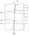
- FIG. 6 is a development view in which the cap rubber portion is developed in a plane together with the second conductive winding portion.
- FIG. 7 is an explanatory view showing a tread rubber molding step.
- FIG. 8 is an explanatory view showing the base rubber portion forming step together with the first conductive winding portion forming step.
- FIG. 9 is an explanatory view showing the cap rubber portion forming step together with the second conductive winding portion forming step.
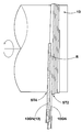
- FIG. 10 is a schematic cross-sectional view conceptually showing a tire electrical resistance measuring apparatus.
- 11A to 11C are cross-sectional views illustrating the background art.
- FIG. 1 is a cross-sectional view of a pneumatic tire 1 obtained by the manufacturing method of the present invention.
- a pneumatic tire 1 according to the present embodiment includes a toroidal carcass 6 extending from a tread portion 2 through a sidewall portion 3 to a bead core 5 of a bead portion 4, a radially outer side of the carcass 6 and the tread. And a tread reinforcing cord layer 7 disposed inside the portion 2.
- the carcass 6 is formed by one or more carcass plies 6A in this example, in which carcass cords are arranged at an angle of, for example, 75 ° to 90 ° with respect to the tire circumferential direction.
- the carcass ply 6A includes, for example, ply turn-up portions 6b that are turned around the bead core 5 from the inner side to the outer side in the tire axial direction on both sides of a toroid-like ply main body portion 6a straddling the bead cores 5 and 5.
- a bead apex rubber 8 for bead reinforcement extending radially outward from the bead core 5 is disposed between the ply body portion 6a and the ply turn-up portion 6b.
- the tread reinforcing cord layer 7 includes two or more belt plies 7A and 7B in this example, in which belt cords are arranged at an angle of, for example, 15 to 40 ° with respect to the tire circumferential direction.
- the tread reinforcing cord layer 7 increases belt rigidity by crossing the belt cords between the plies, and reinforces substantially the entire width of the tread portion 2 with a tagging effect.
- a band ply 19 in which a band cord is spirally wound in the tire circumferential direction can also be included.
- the carcass ply 6A, belt plies 7A and 7B, and band ply 19 all include a topping rubber that covers the cord.
- each topping rubber is compounded with carbon black as a rubber reinforcing agent in the same manner as a conventional general tire, and thereby the volume specific electrical resistance value of the rubber is 1.0 ⁇ 10 8 ( ⁇ ⁇ cm). Less than, preferably 1.0 ⁇ 10 7 ( ⁇ ⁇ cm) or less, ensures conductivity.
- the volume specific electric resistance value of rubber is an electric resistance measuring instrument (in this example, in the case of an applied voltage of 500 V, an air temperature of 25 ° C., and a humidity of 50% for a rubber sample of 15 cm square and 2 mm thick. It is displayed with the value measured using ADVANTESTER 8340A.
- a sidewall rubber 3 ⁇ / b> G that forms the outer surface of the sidewall is disposed on the sidewall portion 3 outside the carcass 6.
- the outer end of the sidewall rubber 3G in the tire radial direction is sandwiched between the carcass 6 and the tread reinforcing cord layer 7 and terminates.
- the bead portion 4 is provided with clinch rubber 4G that contacts the rim J outside the carcass 6.
- the upper end portion in the radial direction of the clinch rubber 4G is connected to the lower end portion in the radial direction of the sidewall rubber 3G.
- the side wall rubber 3G and the clinch rubber 4G are also highly blended with carbon black as a rubber reinforcing agent, whereby the volume specific electric resistance value is less than 1.0 ⁇ 10 8 ( ⁇ ⁇ cm), preferably 1.0. ⁇ 10 7 ⁇ ⁇ cm) or less to ensure conductivity.
- the tread reinforcing cord layer 7 is in the rim assembled state, the topping rubber of the band ply 19, the topping rubber of the belt plies 7A and 7B, the topping rubber of the carcass ply 6A, the side wall rubber 3G, and the clinch rubber 4G. It can be electrically connected to the rim J via If the electrical continuity is maintained, a part of the topping rubber and / or the side wall rubber 3G is made of a non-conductive rubber having a volume specific electric resistance value of 1.0 ⁇ 10 8 ( ⁇ ⁇ cm) or more. It can also be formed.
- a tread ground surface SU in which the radially inner peripheral surface forms a contact surface SL in contact with the tread reinforcing cord layer 7 and the radial outer peripheral surface contacts the road surface.
- a tread rubber 2G is arranged.
- the tread rubber 2G includes a base rubber portion 9 on the inner side in the radial direction having the contact surface SL, a cap rubber portion 10 having the tread grounding surface SU and overlaid on the outer side in the radial direction with the base rubber portion 9. Conduction that extends through the base rubber portion 9 and the cap rubber portion 10 inward and outward in the radial direction, with the radially inner end exposed at the contact surface SL, and the radially outer end exposed at the tread ground surface SU.
- the unit 11 is configured to be included.
- the base rubber portion 9 spirals the first non-conductive rubber strip 9G containing silica from one tread end Te1 side to the other tread end Te2 side, as shown in an enlarged view in FIG. It is formed by the strip winding body wound continuously in the shape.
- the cap rubber portion 10 is formed of a strip wound body in which a second non-conductive rubber strip 10G containing silica is spirally wound from the other tread end Te2 side toward the one tread end Te1 side. It is formed.
- Both side edges of the first non-conductive rubber strip 9G constitute the radially inner and outer peripheral surfaces of the base rubber part 9, and both side edges of the second non-conductive rubber strip 10G are cap rubber parts. 10 radial inner peripheral surfaces and outer peripheral surfaces are formed.
- the first and second non-conductive rubber strips 9G and 10G silica compound rubber containing high silica is used.
- a silica-containing rubber can improve the wet grip performance in the cap rubber portion 10 while reducing rolling resistance. Further, in the base rubber part 9, the rolling resistance can be mainly reduced. Therefore, comprehensively, the wet grip performance and the low rolling resistance are combined at a high level, and the excellent actual vehicle running performance can be exhibited.
- the second non-conductive rubber strip 10G has a tangent loss tan ⁇ 2 larger than the tangent loss tan ⁇ 1 of the first non-conductive rubber strip 9G. Further improvement is planned.
- the tangent loss ratio tan ⁇ 2 / tan ⁇ 1 is preferably 1.5 or more, more preferably 2.0 or more, and more preferably 2.5 or more. However, if it is too high, the rolling resistance is adversely affected.
- the upper limit is desirably 5.0 or less.
- examples of the rubber polymer constituting the first and second non-conductive rubber strips 9G and 10G include natural rubber (NR), butadiene rubber (BR), styrene butadiene rubber (SBR), and polyisoprene rubber (IR), nitrile rubber (NBR), chloroprene rubber (CR), and the like. These may be used alone or in combination of two or more.
- natural rubber NR
- butadiene rubber BR
- SBR styrene butadiene rubber
- IR polyisoprene rubber
- NBR nitrile rubber
- CR chloroprene rubber
- the silica to be blended is not particularly limited, but in order to enhance the reinforcing effect on rubber and rubber processability, the nitrogen adsorption specific surface area (BET) is in the range of 150 to 250 m 2 / g, and dibutyl phthalate (DBP) What shows the colloidal characteristic whose oil absorption amount is 180 ml / 100g or more is suitable.
- BET nitrogen adsorption specific surface area
- DBP dibutyl phthalate
- the silane coupling agent bis (triethoxysilylpropyl) tetrasulfide and ⁇ -mercaptopropyltrimethoxysilane are suitable.
- the amount of silica is preferably 30 parts by mass or more, more preferably 40 parts by mass or more, with respect to 100 parts by mass of the rubber polymer.
- the upper limit is preferably 100 parts by mass or less, more preferably 80 parts by mass or less, and still more preferably 60 parts by mass or less.
- Carbon black may be supplementarily blended in the first and second non-conductive rubber strips 9G and 10G. This is useful for adjusting other rubber physical properties such as rubber elasticity and rubber hardness.
- the compounding amount of carbon black is less than the compounding amount of silica, and is particularly preferably 15 parts by mass or less, more preferably 10 parts by mass or less with respect to 100 parts by mass of the rubber polymer.
- the blending amount of the carbon black exceeds 15 parts by mass, the rolling resistance is greatly deteriorated and the rubber tends to be excessively hard.
- the first and second non-conductive rubber strips 9G and 10G have a ribbon shape with a rectangular cross section having a width Wg sufficiently larger than the thickness tg.
- the width Wg and the thickness tg of the rubber strips 9G and 10G vary depending on the tire size and the type thereof, but those having a width Wg of about 5 to 50 mm and a thickness tg of about 0.5 to 3 mm are preferably used. it can.
- the width Wg is less than 5 mm or the thickness tg is less than 0.5 mm, the rubber strip is easily broken during winding, and the number of windings is remarkably increased to form the tread rubber 2G. May decrease.
- the width Wg exceeds 50 mm, or when the thickness tg exceeds 3 mm it is difficult to make an accurate cross-sectional shape by spirally winding.
- the conductive portion 11 is formed in the first conductive winding portion 12 formed in the base rubber portion 9 and the cap rubber portion 10 as further enlarged and shown in FIG. It consists of a second conductive winding part 13.
- the first conductive winding portion 12 is interposed between the winding portions R and R of the first non-conductive rubber strip 9G adjacent in the tire rubber direction in the base rubber portion 9.
- the first non-conductive rubber strip 9G is formed from the first conductive rubber strip 12G spirally wound.
- the number N of windings of the first conductive rubber strip 12G is a plurality of times, and if it is too large, it is disadvantageous for rolling resistance, and if it is too small, also in the present invention. Accuracy is required for conduction between the first conductive winding portion 12 and the second conductive winding portion 13, which is disadvantageous in production efficiency.
- the lower limit of the winding number N is preferably 2 times or more, more preferably 3 times or more, and the upper limit thereof is preferably 10 times or less, more preferably 5 times or less.
- the second conductive winding portion 13 is interposed between the winding portions R and R of the second non-conductive rubber strip 10G adjacent in the tire axial direction in the cap rubber portion 10.
- the second conductive rubber strip 13G is spirally wound together with the two non-conductive rubber strips 10G.
- the winding of the second conductive rubber strip 13G is less than one turn, and as shown in FIG. 6, the start end E1 and the end portion of this winding
- the distance D between the E2 and the circumferential direction D on the tread contact surface SU is 100% or less of the tread contact length L. If it exceeds 100%, a state in which the second conductive winding portion 13 is not in contact with the road surface occurs during traveling, which is extremely disadvantageous for the discharge.
- the distance D is preferably 70% or less, and more preferably 50% or less. As described above, since the second conductive winding portion 13 is stopped at the minimum winding necessary for discharging, the wet grip performance and the low rolling resistance performance can be maximized.
- the width of the first conductive rubber strip 12G is substantially equal to the width Wg of the first non-conductive rubber strip 9G
- the width of the second conductive rubber strip 13G is the second width of the second conductive rubber strip 13G. It is substantially equal to the width Wg of the non-conductive rubber strip 10G.
- the upper end 12U in the radial direction of the first conductive winding portion 12 is exposed in alignment with the outer peripheral surface 9SU in the radial direction of the base rubber portion 9, and as conceptually shown in FIG.
- a first exposed surface portion 12SU extending obliquely with respect to the tire circumferential direction on the outer peripheral surface 9SU is formed.
- the lower end portion 13L in the radial direction of the first conductive winding portion 13 is exposed in alignment with the radially inner peripheral surface 10SL of the cap rubber portion 10, and as indicated by a one-dot chain line in FIG.
- a second exposed surface portion 13SL extending on the inner peripheral surface 10SL is inclined with respect to the tire circumferential direction.
- the first conductive rubber strip 12G together with the first non-conductive rubber strip 9G, is spirally wound from one tread end Te1 side to the other tread end Te2 side. Yes. Therefore, the first exposed surface portion 12SU is inclined downward in the right direction in FIG. 5 with respect to the tire circumferential direction by the pitch angle ⁇ of the spiral.
- the second conductive rubber strip 13G together with the second non-conductive rubber strip 10G, is spirally wound from the other tread end Te2 side toward the one tread end Te1 side. Therefore, the second exposed surface portion 13SL is inclined downwardly to the left in FIG. 5 with respect to the tire circumferential direction by the amount of the pitch angle ⁇ of the spiral.
- the exposed surface portions 12SU and 13SL can intersect with each other. Therefore, the first and second conductive winding portions 12 and 13 are It becomes possible to conduct each other at the intersection position P.
- the first conductive winding portion 12 is wound a plurality of times, the first conductive winding portion 12 can intersect at two places, and the second conductive winding is within the width region Y of the first conductive winding portion 12. Even when the forming position of the turning portion 13 varies, the exposed surface portion 12SU and the exposed surface portion 13SL can be reliably crossed.
- the first and second conductive rubber strips 12G and 13G have a conductivity similar to that of the topping rubber and the like by using a carbon black compounded rubber in which carbon black is highly compounded in this example as a rubber reinforcing agent. Secured.
- the radial thickness Tc of the cap rubber portion 10 at the tire equator C and the base rubber The ratio Tc / Tb of the portion 9 with respect to the radial thickness Tb needs to be larger than 1.0, preferably 2.0 or more.
- the upper limit of the ratio Tc / Tb is preferably 4.0 or less, and more preferably 3.0 or less, in order to balance the lamination.
- This manufacturing method includes a tread rubber molding step for molding a tread rubber and a vulcanization step for vulcanizing a raw tire having the tread rubber in a tread portion, except for the tread rubber molding step. A process is adopted. Therefore, only the tread rubber molding process will be described below.
- the raw non-conductive rubber strip 9GN mixed with silica is placed on the outer side in the tire radial direction of the tread reinforcing cord layer 7 from the one tread end Te1 side to the other.
- First conductive winding portion forming step for forming a first conductive winding portion 12 composed of a raw first conductive rubber strip 12GN spirally wound together with the first non-conductive rubber strip 9GN. includes ST3.
- the cap rubber part forming step ST2 is also the same. As shown in FIG. 9, in the course of winding the raw second non-conductive rubber strip 10GN, the raw second non-conductive rubber strip 10GN is wound. Between the winding portions R and R of the raw second non-conductive rubber strip 10G adjacent to each other in the tire axial direction by inserting the raw second conductive rubber strip 13GN having substantially the same width. A second conductive winding forming a second conductive winding portion 13 composed of a raw second conductive rubber strip 13GN spirally wound with the raw second non-conductive rubber strip 10G. A part forming step ST4 is included.
- the first and second conductive winding portions 12 and 13 are configured so that the first and second conductive winding portions 12 and 13 are wound when the raw first and second nonconductive rubber strips 9GN and 10GN are wound. Can be formed by interrupting and winding the conductive rubber strips 12GN, 13GN. Therefore, excellent production efficiency can be exhibited.
- a pneumatic tire (size: 225 / 50R17) having the basic structure shown in FIG. 1 is prototyped based on the specifications in Table 1, and the productivity, uniformity, occurrence rate of defective products due to air accumulation, and electrical resistance are measured. Measured and compared with each tire.
- a silica-rich non-conductive rubber is used for the cap rubber part and the base rubber part, and a carbon-rich conductive rubber is used for the conductive part.
- the formulation is the same for each example.
- Comparative Example 1A shows the case where the tread rubber is extruded as shown in FIG. 11A, and Comparative Examples 2A, 3A and Example 1A other than that are the strip wind method (STW method).
- a tread rubber is formed.
- Comparative Examples 2A and 3A as shown in FIG. 11C, the conductive portions are formed by winding the rubber strips in a spiral shape so as to be stacked radially outward.
- the left and right base rubber portions and the cap rubber portion divided by the conducting portion are separately formed using rubber strips.
- the test method is as follows.
- the insulating plate 20 (electric resistance 10 12 Omega higher) plate metal installation surface is polished on a 21 (electric resistance 10 ⁇ or less), tire rim assembly
- the electrical resistance value of the assembly of the test tire and the rim J was measured in accordance with JATMA regulations using a measuring device including a conductive tire mounting shaft 22 that holds the tire and an electrical resistance measuring device 23.
- Each test tire 1 was a tire in which the surface release agent and dirt were sufficiently removed in advance and were sufficiently dried. Other conditions are as follows.
- Rim material Aluminum alloy Rim size: 17 ⁇ 7J Internal pressure: 200 kPa Load: 5.3kN Test environment temperature (test room temperature): 25 ° C Humidity: 50% Measuring range of electric resistance measuring device: 10 3 to 1.6 ⁇ 10 16 ⁇ Test voltage (applied voltage): 1000V
- the test procedure is as follows. (1) A test tire 1 is mounted on a rim to prepare a tire / rim assembly. At this time, soapy water is used as a lubricant at the contact portion between the two. (2) The tire / rim assembly is allowed to stand in the test room for 2 hours and then attached to the tire mounting shaft 22. (3) The tire / rim assembly is loaded with the load for 0.5 minutes, and further for 0.5 minutes after being released and for 2 minutes after being released. (4) When the test voltage is applied and 5 minutes have passed, the electrical resistance value between the tire mounting shaft 22 and the metal plate 21 is measured by the electrical resistance measuring instrument 23. The measurement is performed at four positions at 90 ° intervals in the tire circumferential direction, and the maximum value among them is taken as the electrical resistance value (measured value) of the tire T.
- radial force variation which is a fluctuation component of force in the tire radial direction during rotation
- each RFV was reciprocally evaluated, and in Table 1, an evaluation was performed with an index in which Comparative Example 1A was 100 and Comparative Example 1B was 100 in Table 2. The larger the value, the better.
- Rim 17 ⁇ 7J
- Internal pressure 200 kPa Load: 4.08kN
- Rotation speed 60rpm Table 1 shows the test results.
- the tires of the examples can suppress the occurrence of air accumulation, thereby suppressing the occurrence of product defects, improving the uniformity, and improving the productivity.
Priority Applications (5)
| Application Number | Priority Date | Filing Date | Title |
|---|---|---|---|
| US13/266,874 US9138953B2 (en) | 2009-05-18 | 2010-03-17 | Pneumatic tire and method of manufacturing same |
| RU2011143974/11A RU2508206C2 (ru) | 2009-05-18 | 2010-03-17 | Пневматическая шина |
| EP10777614.8A EP2418104B1 (de) | 2009-05-18 | 2010-03-17 | Luftreifen und herstellungsverfahren dafür |
| BRPI1012846A BRPI1012846A2 (pt) | 2009-05-18 | 2010-03-17 | pneu e método de fabricar o mesmo |
| CN201080022096.1A CN102427959B (zh) | 2009-05-18 | 2010-03-17 | 充气轮胎及其制造方法 |
Applications Claiming Priority (2)
| Application Number | Priority Date | Filing Date | Title |
|---|---|---|---|
| JP2009-120116 | 2009-05-18 | ||
| JP2009120116A JP5155935B2 (ja) | 2009-05-18 | 2009-05-18 | 空気入りタイヤ及びその製造方法 |
Publications (1)
| Publication Number | Publication Date |
|---|---|
| WO2010134379A1 true WO2010134379A1 (ja) | 2010-11-25 |
Family
ID=43126068
Family Applications (1)
| Application Number | Title | Priority Date | Filing Date |
|---|---|---|---|
| PCT/JP2010/054501 WO2010134379A1 (ja) | 2009-05-18 | 2010-03-17 | 空気入りタイヤ及びその製造方法 |
Country Status (8)
| Country | Link |
|---|---|
| US (1) | US9138953B2 (de) |
| EP (1) | EP2418104B1 (de) |
| JP (1) | JP5155935B2 (de) |
| KR (1) | KR101587310B1 (de) |
| CN (1) | CN102427959B (de) |
| BR (1) | BRPI1012846A2 (de) |
| RU (1) | RU2508206C2 (de) |
| WO (1) | WO2010134379A1 (de) |
Cited By (1)
| Publication number | Priority date | Publication date | Assignee | Title |
|---|---|---|---|---|
| US20180170112A1 (en) * | 2016-12-21 | 2018-06-21 | Toyo Tire & Rubber Co., Ltd. | Tire |
Families Citing this family (16)
| Publication number | Priority date | Publication date | Assignee | Title |
|---|---|---|---|---|
| JP5630865B2 (ja) * | 2010-12-20 | 2014-11-26 | 東洋ゴム工業株式会社 | 空気入りタイヤ及びその製造方法 |
| JP5427250B2 (ja) * | 2012-01-16 | 2014-02-26 | 住友ゴム工業株式会社 | 空気入りタイヤ、及びその製造方法 |
| DE102012106464A1 (de) * | 2012-07-18 | 2014-02-20 | Continental Reifen Deutschland Gmbh | Verfahren zur Herstellung von Fahrzeugreifen |
| JP6084444B2 (ja) * | 2012-11-22 | 2017-02-22 | 東洋ゴム工業株式会社 | 空気入りタイヤ及びその製造方法 |
| JP6077281B2 (ja) * | 2012-11-22 | 2017-02-08 | 東洋ゴム工業株式会社 | 空気入りタイヤ及びその製造方法 |
| US20140138006A1 (en) * | 2012-11-22 | 2014-05-22 | Toyo Tire & Rubber Co., Ltd. | Pneumatic tire and manufacturing method of the same |
| JP6147650B2 (ja) * | 2013-11-22 | 2017-06-14 | 住友ゴム工業株式会社 | 空気入りタイヤの製造方法 |
| US10336141B2 (en) | 2013-12-19 | 2019-07-02 | Bridgestone Americas Tire Operations, Llc | Tire having static charge dissipation element |
| JP6325305B2 (ja) * | 2014-03-27 | 2018-05-16 | 住友ゴム工業株式会社 | 空気入りタイヤ |
| JP6329434B2 (ja) * | 2014-05-20 | 2018-05-23 | 住友ゴム工業株式会社 | 空気入りタイヤ |
| JP6289309B2 (ja) * | 2014-08-26 | 2018-03-07 | 東洋ゴム工業株式会社 | 空気入りタイヤ |
| JP6281501B2 (ja) * | 2015-01-29 | 2018-02-21 | トヨタ自動車株式会社 | 車両の車輪支持装置 |
| DE102015207931A1 (de) * | 2015-04-29 | 2016-11-03 | Continental Reifen Deutschland Gmbh | Fahrzeugluftreifen mit einem Laufstreifen |
| EP3481652B1 (de) * | 2016-07-07 | 2020-09-16 | Bridgestone Americas Tire Operations, LLC | Elektrisch leitender kautschukstreifen |
| DE102017108943A1 (de) * | 2016-12-02 | 2018-06-07 | Kraussmaffei Berstorff Gmbh | Verfahren zum Herstellen eines Laufstreifens und Laufstreifen-Herstellvorrichtung |
| JP2021130222A (ja) | 2020-02-18 | 2021-09-09 | 住友ゴム工業株式会社 | トレッドゴム形成方法及びトレッドゴム形成装置 |
Citations (7)
| Publication number | Priority date | Publication date | Assignee | Title |
|---|---|---|---|---|
| JPH0971112A (ja) | 1994-12-21 | 1997-03-18 | Sumitomo Rubber Ind Ltd | 空気入りタイヤ及びその製造方法 |
| JP2003326614A (ja) * | 2002-05-13 | 2003-11-19 | Bridgestone Corp | タイヤ用トレッドの製造方法およびタイヤ |
| JP2004338621A (ja) * | 2003-05-16 | 2004-12-02 | Toyo Tire & Rubber Co Ltd | 空気入りタイヤ及びその空気入りタイヤの製造方法 |
| JP2005035337A (ja) * | 2003-07-16 | 2005-02-10 | Bridgestone Corp | タイヤおよびタイヤの製造方法 |
| JP2005041055A (ja) * | 2003-07-25 | 2005-02-17 | Yokohama Rubber Co Ltd:The | タイヤの製造方法及びその製造方法により製造されたタイヤ |
| JP2006137067A (ja) | 2004-11-11 | 2006-06-01 | Sumitomo Rubber Ind Ltd | 空気入りタイヤの製造方法 |
| JP2008285070A (ja) | 2007-05-18 | 2008-11-27 | Sumitomo Rubber Ind Ltd | 空気入りタイヤ |
Family Cites Families (7)
| Publication number | Priority date | Publication date | Assignee | Title |
|---|---|---|---|---|
| US6415833B1 (en) * | 1996-07-18 | 2002-07-09 | Bridgestone Corporation | Pneumatic tire having electrically conductive rubber layer in land portion defined between circumferential grooves |
| JPH11240312A (ja) * | 1997-08-04 | 1999-09-07 | Bridgestone Corp | 空気入りタイヤ |
| FR2775220A1 (fr) | 1998-02-26 | 1999-08-27 | Michelin & Cie | Pneumatique conducteur d'electricite et appareillage d'extrusion d'un profile avec insert conducteur |
| JP4205256B2 (ja) * | 1999-06-09 | 2009-01-07 | 東洋ゴム工業株式会社 | タイヤ用トレッドの押出し成形方法および装置 |
| JP4343387B2 (ja) * | 2000-03-27 | 2009-10-14 | 東洋ゴム工業株式会社 | 空気入りタイヤのトレッド構造とその製造方法 |
| JP4510557B2 (ja) * | 2004-09-01 | 2010-07-28 | 住友ゴム工業株式会社 | ゴムストリップ巻付体の形成装置 |
| DE102007004327A1 (de) | 2007-01-29 | 2008-07-31 | Continental Aktiengesellschaft | Verfahren zur Herstellung eines Fahrzeugluftreifens und Fahrzeugluftreifen |
-
2009
- 2009-05-18 JP JP2009120116A patent/JP5155935B2/ja not_active Expired - Fee Related
-
2010
- 2010-03-17 CN CN201080022096.1A patent/CN102427959B/zh not_active Expired - Fee Related
- 2010-03-17 EP EP10777614.8A patent/EP2418104B1/de not_active Not-in-force
- 2010-03-17 RU RU2011143974/11A patent/RU2508206C2/ru not_active IP Right Cessation
- 2010-03-17 BR BRPI1012846A patent/BRPI1012846A2/pt not_active IP Right Cessation
- 2010-03-17 WO PCT/JP2010/054501 patent/WO2010134379A1/ja active Application Filing
- 2010-03-17 US US13/266,874 patent/US9138953B2/en not_active Expired - Fee Related
- 2010-03-17 KR KR1020117027396A patent/KR101587310B1/ko not_active IP Right Cessation
Patent Citations (7)
| Publication number | Priority date | Publication date | Assignee | Title |
|---|---|---|---|---|
| JPH0971112A (ja) | 1994-12-21 | 1997-03-18 | Sumitomo Rubber Ind Ltd | 空気入りタイヤ及びその製造方法 |
| JP2003326614A (ja) * | 2002-05-13 | 2003-11-19 | Bridgestone Corp | タイヤ用トレッドの製造方法およびタイヤ |
| JP2004338621A (ja) * | 2003-05-16 | 2004-12-02 | Toyo Tire & Rubber Co Ltd | 空気入りタイヤ及びその空気入りタイヤの製造方法 |
| JP2005035337A (ja) * | 2003-07-16 | 2005-02-10 | Bridgestone Corp | タイヤおよびタイヤの製造方法 |
| JP2005041055A (ja) * | 2003-07-25 | 2005-02-17 | Yokohama Rubber Co Ltd:The | タイヤの製造方法及びその製造方法により製造されたタイヤ |
| JP2006137067A (ja) | 2004-11-11 | 2006-06-01 | Sumitomo Rubber Ind Ltd | 空気入りタイヤの製造方法 |
| JP2008285070A (ja) | 2007-05-18 | 2008-11-27 | Sumitomo Rubber Ind Ltd | 空気入りタイヤ |
Non-Patent Citations (1)
| Title |
|---|
| See also references of EP2418104A4 * |
Cited By (2)
| Publication number | Priority date | Publication date | Assignee | Title |
|---|---|---|---|---|
| US20180170112A1 (en) * | 2016-12-21 | 2018-06-21 | Toyo Tire & Rubber Co., Ltd. | Tire |
| US10688829B2 (en) * | 2016-12-21 | 2020-06-23 | Toyo Tire Corporation | Tire |
Also Published As
| Publication number | Publication date |
|---|---|
| BRPI1012846A2 (pt) | 2016-08-23 |
| US9138953B2 (en) | 2015-09-22 |
| KR20120022974A (ko) | 2012-03-12 |
| RU2508206C2 (ru) | 2014-02-27 |
| EP2418104A4 (de) | 2013-08-07 |
| RU2011143974A (ru) | 2013-06-27 |
| EP2418104A1 (de) | 2012-02-15 |
| JP5155935B2 (ja) | 2013-03-06 |
| US20120048434A1 (en) | 2012-03-01 |
| KR101587310B1 (ko) | 2016-01-20 |
| CN102427959A (zh) | 2012-04-25 |
| CN102427959B (zh) | 2014-06-11 |
| EP2418104B1 (de) | 2014-07-30 |
| JP2010264959A (ja) | 2010-11-25 |
Similar Documents
| Publication | Publication Date | Title |
|---|---|---|
| JP5155935B2 (ja) | 空気入りタイヤ及びその製造方法 | |
| JP4392444B2 (ja) | 空気入りタイヤ及びその製造方法 | |
| JP4575979B2 (ja) | 空気入りタイヤ及びその製造方法 | |
| JP4220569B1 (ja) | 空気入りタイヤ | |
| KR101492670B1 (ko) | 공기 타이어 및 이의 제조 방법 | |
| JP4299811B2 (ja) | 空気入りタイヤ、その製造方法及びゴムストリップ | |
| JP5027643B2 (ja) | 空気入りタイヤ | |
| JP4464917B2 (ja) | 空気入りタイヤ | |
| JP5266132B2 (ja) | 空気入りタイヤ | |
| JP5624369B2 (ja) | 空気入りタイヤ及びその製造方法 | |
| EP2805838B1 (de) | Luftreifen und verfahren zur herstellung davon | |
| JP5860339B2 (ja) | 空気入りタイヤ | |
| JP4956070B2 (ja) | 空気入りタイヤ、及びその製造方法 | |
| JP4571664B2 (ja) | 空気入りタイヤ及びその製造方法 |
Legal Events
| Date | Code | Title | Description |
|---|---|---|---|
| WWE | Wipo information: entry into national phase |
Ref document number: 201080022096.1 Country of ref document: CN |
|
| 121 | Ep: the epo has been informed by wipo that ep was designated in this application |
Ref document number: 10777614 Country of ref document: EP Kind code of ref document: A1 |
|
| WWE | Wipo information: entry into national phase |
Ref document number: 7594/CHENP/2011 Country of ref document: IN |
|
| WWE | Wipo information: entry into national phase |
Ref document number: 13266874 Country of ref document: US |
|
| WWE | Wipo information: entry into national phase |
Ref document number: 2010777614 Country of ref document: EP |
|
| ENP | Entry into the national phase |
Ref document number: 20117027396 Country of ref document: KR Kind code of ref document: A |
|
| NENP | Non-entry into the national phase |
Ref country code: DE |
|
| ENP | Entry into the national phase |
Ref document number: 2011143974 Country of ref document: RU Kind code of ref document: A |
|
| REG | Reference to national code |
Ref country code: BR Ref legal event code: B01A Ref document number: PI1012846 Country of ref document: BR |
|
| ENP | Entry into the national phase |
Ref document number: PI1012846 Country of ref document: BR Kind code of ref document: A2 Effective date: 20111118 |