WO2010126020A1 - 触媒およびその製造方法ならびにその用途 - Google Patents
触媒およびその製造方法ならびにその用途 Download PDFInfo
- Publication number
- WO2010126020A1 WO2010126020A1 PCT/JP2010/057414 JP2010057414W WO2010126020A1 WO 2010126020 A1 WO2010126020 A1 WO 2010126020A1 JP 2010057414 W JP2010057414 W JP 2010057414W WO 2010126020 A1 WO2010126020 A1 WO 2010126020A1
- Authority
- WO
- WIPO (PCT)
- Prior art keywords
- catalyst
- gas
- fuel cell
- carbon
- oxygen
- Prior art date
Links
Images


Classifications
-
- H—ELECTRICITY
- H01—ELECTRIC ELEMENTS
- H01M—PROCESSES OR MEANS, e.g. BATTERIES, FOR THE DIRECT CONVERSION OF CHEMICAL ENERGY INTO ELECTRICAL ENERGY
- H01M4/00—Electrodes
- H01M4/86—Inert electrodes with catalytic activity, e.g. for fuel cells
- H01M4/90—Selection of catalytic material
- H01M4/9016—Oxides, hydroxides or oxygenated metallic salts
-
- B—PERFORMING OPERATIONS; TRANSPORTING
- B01—PHYSICAL OR CHEMICAL PROCESSES OR APPARATUS IN GENERAL
- B01J—CHEMICAL OR PHYSICAL PROCESSES, e.g. CATALYSIS OR COLLOID CHEMISTRY; THEIR RELEVANT APPARATUS
- B01J27/00—Catalysts comprising the elements or compounds of halogens, sulfur, selenium, tellurium, phosphorus or nitrogen; Catalysts comprising carbon compounds
- B01J27/24—Nitrogen compounds
-
- B—PERFORMING OPERATIONS; TRANSPORTING
- B01—PHYSICAL OR CHEMICAL PROCESSES OR APPARATUS IN GENERAL
- B01J—CHEMICAL OR PHYSICAL PROCESSES, e.g. CATALYSIS OR COLLOID CHEMISTRY; THEIR RELEVANT APPARATUS
- B01J21/00—Catalysts comprising the elements, oxides, or hydroxides of magnesium, boron, aluminium, carbon, silicon, titanium, zirconium, or hafnium
- B01J21/06—Silicon, titanium, zirconium or hafnium; Oxides or hydroxides thereof
-
- H—ELECTRICITY
- H01—ELECTRIC ELEMENTS
- H01M—PROCESSES OR MEANS, e.g. BATTERIES, FOR THE DIRECT CONVERSION OF CHEMICAL ENERGY INTO ELECTRICAL ENERGY
- H01M4/00—Electrodes
- H01M4/86—Inert electrodes with catalytic activity, e.g. for fuel cells
- H01M4/90—Selection of catalytic material
-
- H—ELECTRICITY
- H01—ELECTRIC ELEMENTS
- H01M—PROCESSES OR MEANS, e.g. BATTERIES, FOR THE DIRECT CONVERSION OF CHEMICAL ENERGY INTO ELECTRICAL ENERGY
- H01M8/00—Fuel cells; Manufacture thereof
- H01M8/10—Fuel cells with solid electrolytes
-
- H—ELECTRICITY
- H01—ELECTRIC ELEMENTS
- H01M—PROCESSES OR MEANS, e.g. BATTERIES, FOR THE DIRECT CONVERSION OF CHEMICAL ENERGY INTO ELECTRICAL ENERGY
- H01M8/00—Fuel cells; Manufacture thereof
- H01M8/10—Fuel cells with solid electrolytes
- H01M2008/1095—Fuel cells with polymeric electrolytes
-
- Y—GENERAL TAGGING OF NEW TECHNOLOGICAL DEVELOPMENTS; GENERAL TAGGING OF CROSS-SECTIONAL TECHNOLOGIES SPANNING OVER SEVERAL SECTIONS OF THE IPC; TECHNICAL SUBJECTS COVERED BY FORMER USPC CROSS-REFERENCE ART COLLECTIONS [XRACs] AND DIGESTS
- Y02—TECHNOLOGIES OR APPLICATIONS FOR MITIGATION OR ADAPTATION AGAINST CLIMATE CHANGE
- Y02E—REDUCTION OF GREENHOUSE GAS [GHG] EMISSIONS, RELATED TO ENERGY GENERATION, TRANSMISSION OR DISTRIBUTION
- Y02E60/00—Enabling technologies; Technologies with a potential or indirect contribution to GHG emissions mitigation
- Y02E60/30—Hydrogen technology
- Y02E60/50—Fuel cells
Definitions
- the present invention relates to a catalyst, a production method thereof, and an application thereof.
- Catalysts have the function of accelerating the rate of reaction that should proceed in terms of chemical equilibrium by lowering the activation energy of the reaction, and are used in a wide variety of chemical reaction processes such as synthesis and decomposition.
- the catalyst includes a homogeneous catalyst and a heterogeneous catalyst.
- the homogeneous catalyst is, for example, a catalyst dispersed in a solvent by dissolution or the like. By using such a homogeneous catalyst, the synthesis of the target compound can be efficiently advanced in the liquid phase or the like.
- the heterogeneous catalyst is a catalyst in which a catalyst is fixed to a carrier.
- heterogeneous catalyst By using such a heterogeneous catalyst, the target substance can be efficiently synthesized or decomposed, and the catalyst can be easily separated and recovered from the product substance. Therefore, such heterogeneous catalysts are particularly useful in large-scale chemical synthesis factories.
- a catalyst having a catalyst fixed on the electrode surface is called an electrode catalyst.
- Electrocatalysts are particularly required for fuel cells for the purpose of reducing overvoltage and generating more electrical energy.
- Fuel cells are classified into various types according to the type of electrolyte and the type of electrode, and representative types include alkaline type, phosphoric acid type, molten carbonate type, solid electrolyte type, and solid polymer type.
- a polymer electrolyte fuel cell that can operate at a low temperature (about ⁇ 40 ° C.) to about 120 ° C. attracts attention, and in recent years, development and practical application as a low-pollution power source for automobiles is progressing.
- a use of the polymer electrolyte fuel cell a vehicle driving source and a stationary power source are being studied. However, in order to be applied to these uses, durability over a long period of time is required.
- a polymer solid electrolyte is sandwiched between an anode and a cathode, fuel is supplied to the anode, oxygen or air is supplied to the cathode, and oxygen is reduced at the cathode to extract electricity.
- Hydrogen or methanol is mainly used as the fuel.
- the fuel cell cathode (air electrode) surface or anode (fuel electrode) surface has a layer containing a catalyst (hereinafter referred to as “for fuel cell”). Also referred to as “catalyst layer”).
- the noble metal used on the cathode surface may be dissolved in an acidic atmosphere, and there is a problem that it is not suitable for applications that require long-term durability. Therefore, there has been a strong demand for the development of a catalyst that does not corrode in an acidic atmosphere, has excellent durability, and has high oxygen reducing ability.
- Non-Patent Document 1 reports that ZrOxN compounds based on zirconium exhibit oxygen reducing ability.
- Patent Document 1 discloses an oxygen reduction electrode material containing a nitride of one or more elements selected from the group of elements of Group 4, Group 5 and Group 14 of the long periodic table as a platinum substitute material.
- Patent Document 2 discusses the possibility that an oxide having a perovskite structure containing two or more kinds of metals can serve as a platinum substitute catalyst. As shown in the examples, the effect assists platinum. It does not exceed the role as a carrier and does not have sufficient activity.
- platinum is useful not only as a catalyst for the fuel cell, but also as an exhaust gas treatment catalyst or an organic synthesis catalyst, platinum is expensive and has limited resources. There has been a demand for the development of a catalyst that can be used in various applications.
- JP 2007-31781 A Japanese Patent Laid-Open No. 2008-4286
- An object of the present invention is to solve such problems in the prior art, and an object of the present invention is to provide a catalyst that does not corrode in an acidic electrolyte or at a high potential, has excellent durability, and has a high oxygen reduction ability. There is.
- the inventors of the present invention are catalysts containing a metal element M, carbon, nitrogen and oxygen, having at least a carbon-carbon-carbon bond, and the metal element It has been found that a catalyst in which M is one selected from the group consisting of titanium, iron, niobium, zirconium and tantalum does not corrode in an acidic electrolyte or at a high potential, has excellent durability, and has a high oxygen reducing ability. The present invention has been completed.
- the present invention relates to the following (1) to (14), for example.
- the catalyst according to any one of (1) to (4) which is a catalyst for a fuel cell.
- (6) Including a step of reacting a compound gas containing a metal element M selected from the group consisting of titanium, iron, niobium, zirconium and tantalum, a hydrocarbon gas, a nitrogen compound gas, and an oxygen compound gas at 600 to 1600 ° C.
- a compound gas containing a metal element M selected from the group consisting of titanium, iron, niobium, zirconium and tantalum, a hydrocarbon gas, a nitrogen compound gas, and an oxygen compound gas at 600 to 1600 ° C.
- the method includes heating a metal carbonitride containing a metal element M selected from the group consisting of titanium, iron, niobium, zirconium and tantalum in an inert gas containing oxygen gas (1)
- a catalyst layer for a fuel cell comprising the catalyst according to any one of (5).
- An electrode having a fuel cell catalyst layer and a porous support layer, wherein the fuel cell catalyst layer is the fuel cell catalyst layer according to (9) or (10).
- a membrane electrode assembly having a cathode, an anode, and an electrolyte membrane disposed between the cathode and the anode, wherein the cathode and / or the anode is an electrode according to (11) Membrane electrode assembly.
- a fuel cell comprising the membrane electrode assembly according to (12).
- a polymer electrolyte fuel cell comprising the membrane electrode assembly according to (12).
- the catalyst of the present invention does not corrode in an acidic electrolyte or at a high potential, is stable, has a high oxygen reducing ability, and is less expensive than platinum. Therefore, the fuel cell including the catalyst is relatively inexpensive and has excellent performance.
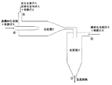
- FIG. 1a is a schematic diagram of a one-stage gas phase reaction reactor.
- FIG. 1 b is an enlarged schematic diagram of a one-stage gas phase reaction reactor.
- FIG. 2 is a schematic diagram of a reactor for a two-stage gas phase reaction.
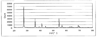
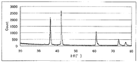
- FIG. 3 is a powder X-ray diffraction spectrum of the catalyst (1) of Example 1.
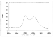
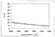
- FIG. 4 is a Raman spectrum of the catalyst (1) of Example 1.
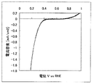
- FIG. 5 is a graph showing an evaluation of the oxygen reducing ability of the catalyst (1) of Example 1.
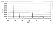
- 6 is a powder X-ray diffraction spectrum of the catalyst (2) of Example 2.
- FIG. 7 is a Raman spectrum of the catalyst (2) of Example 2.
- FIG. 8 is a graph showing an evaluation of the oxygen reducing ability of the catalyst (2) of Example 2.
- FIG. 1a is a schematic diagram of a one-stage gas phase reaction reactor.
- FIG. 1 b is an enlarged schematic diagram of a one-stage gas phase reaction reactor.
- FIG. 2 is
- FIG. 9 is a powder X-ray diffraction spectrum of the catalyst (3) of Example 3.
- FIG. 10 is the Raman spectrum of the catalyst (3) of Example 3.
- FIG. 11 is a graph showing an evaluation of the oxygen reducing ability of the catalyst (3) of Example 3.
- FIG. 12 is a powder X-ray diffraction spectrum of the catalyst (3) of Example 4.
- FIG. 13 is the Raman spectrum of the catalyst (3) of Example 4.
- 14 is a graph showing an evaluation of the oxygen reducing ability of the catalyst (3) of Example 4.
- FIG. FIG. 15 is a powder X-ray diffraction spectrum of the catalyst (4) of Comparative Example 1.
- FIG. 16 is a Raman spectrum of the catalyst (4) of Comparative Example 1.
- FIG. 17 is a graph showing an evaluation of the oxygen reducing ability of the catalyst (4) of Comparative Example 1.
- the catalyst of the present invention is a catalyst containing a metal element M, carbon, nitrogen and oxygen, as measured by Raman spectroscopy, peaks were observed at 1340cm -1 ⁇ 1365cm -1 and 1580cm -1 ⁇ 1610cm -1
- the metal element M is one selected from the group consisting of titanium, iron, niobium, zirconium and tantalum.
- Such a catalyst does not corrode in an acidic electrolyte or at a high potential, has excellent durability, has a high oxygen reducing ability, and is inexpensive compared with platinum.
- the metal element M is titanium, iron, niobium, or zirconium, it is more industrially useful from the viewpoint of the price of the material, and when it is titanium or iron, the oxygen reduction ability of the catalyst becomes higher, Particularly preferred.
- a peak at 1580 cm -1 ⁇ 1610 cm -1 in turn, called the D band, G band.
- the D band is a peak derived from a crystal defect and suggests the presence of an SP3 bond among the bonds between carbons.
- the G band is a peak due to graphite-like bonds, that is, SP2 bonds.
- the catalyst in which such a peak is observed contains carbon that forms SP2 bond and SP3 bond, and has a tendency to improve conductivity and catalytic activity required as an electrode catalyst, and is more preferable.
- the peak observed at 1580 cm ⁇ 1 to 1610 cm ⁇ 1 is considered to be derived from a carbon-carbon unsaturated bond in the catalyst. Further, when measured by Raman spectroscopy, it peaks peak 1340cm -1 ⁇ 1365cm -1 is observed, the carbon in the catalyst - considered to be originated from the carbon saturated bond.
- the present inventors presume that a carbon-carbon-carbon bond is present in the catalyst.
- a catalyst having a carbon-carbon-carbon bond is preferred because it tends to have high oxygen reduction activity. Further, it is more preferable that at least one of the carbon-carbon-carbon bonds is an unsaturated bond, because the conductivity of the catalyst tends to be increased by delocalizing electrons.
- the Raman spectrum observed when measured by Raman spectroscopy may become broad, but in the present invention, the peak observed when measured by Raman spectroscopy means that the sample is irradiated with a laser.
- the noise (N) is the width of the baseline.
- Carbon derived from the G band is carbon having high crystallinity, that is, carbon having high electron conductivity and can serve as a path for supplying electrons necessary as an electrode catalyst.
- carbon derived from the D band is a defect, and the reaction target substance is easily adsorbed, which may contribute to the reaction. There is an optimum ratio between the carbon derived from the D band and the carbon derived from the G band.
- the catalyst of the present invention D the height of the peak of 1340cm -1 ⁇ 1365cm -1, when the height of the peak of 1580cm -1 ⁇ 1610cm -1 was G (however, D and G are baseline It is preferable that D / G is 0.1 or more and 10 or less. When D / G is 0.1 or more and 10 or less, it is considered that electrons are supplied to a site having high activity, which is desirable as an electrode catalyst. Further, D / G is more preferably 0.3 or more and 3 or less, and further preferably 0.5 or more and 2 or less. When D / G is within such a range, the activity as an electrode catalyst is further improved. When D / G is 0.6 or more and 1.2 or less, the fuel cell catalyst tends to have extremely high performance.
- the concentration of carbon forming the SP2 bond and SP3 bond determined by the standard addition method by Raman spectroscopy is preferably 1% by weight or more, preferably 2% by weight or more in terms of furnace black. Is more preferable, and it is further more preferable that it is 5 weight% or more.
- a catalyst containing carbon that forms an SP2 bond and an SP3 bond at such a concentration is preferable because the oxygen reduction activity of the catalyst tends to be good.
- the concentration of carbon forming the SP2 bond and SP3 bond contained in the catalyst of the present invention can be determined by a standard addition method using Raman spectroscopy.
- the standard addition method is a method of adding a standard substance (in the present invention, furnace black (for example, carbon VULCAN XC72 manufactured by CABOT)) to a sample at a constant concentration to create a calibration curve series.
- furnace black for example, carbon VULCAN XC72 manufactured by CABOT
- the catalyst of the present invention has a composition formula: MC x N y O z (where x, y, z represent the ratio of the number of atoms, 0.01 ⁇ x ⁇ 10000, 0.01 ⁇ y ⁇ 10, 0.02) ⁇ z ⁇ 3)).
- MC x N y O z , x, y, and z are more preferably 0.01 ⁇ x ⁇ 1000, 0.01 ⁇ y ⁇ 6, and 0.02 ⁇ z ⁇ 2.5.
- 02 ⁇ z ⁇ 2 and it is extremely preferable that 0.01 ⁇ x ⁇ 2, 0.01 ⁇ y ⁇ 1, and 0.02 ⁇ z ⁇ 2.
- the catalyst in the present invention may be a single compound containing the metal element M, carbon, nitrogen and oxygen as long as the metal element M, carbon, nitrogen and oxygen are detected when elemental analysis of the catalyst is performed.
- a compound containing the metal element M, carbon, nitrogen, and oxygen may or may not be included.
- the catalyst of the present invention is a mixture, it is difficult to individually determine the ratio of carbon, nitrogen and oxygen in each compound. However, if the ratio of carbon, nitrogen, and oxygen in the entire catalyst of the present invention satisfies the composition formula: MC x N y O z as described above, the activity tends to increase.
- the catalyst of the present invention is preferably a fuel cell catalyst.
- the oxygen reduction initiation potential of the catalyst of the present invention is preferably 0.5 V (vs. NHE) or more with respect to the reversible hydrogen electrode.
- carbon carbon black (specific surface area: 100 to 300 m 2 / g) (for example, XC-72 manufactured by Cabot) is used, and the catalyst and carbon are dispersed so that the weight ratio is 95: 5.
- isopropyl alcohol: water (weight ratio) 2: 1 is used.
- the obtained electrode refer to a reversible hydrogen electrode in a sulfuric acid solution of the same concentration at a temperature of 30 ° C. in a 0.5 mol / dm 3 sulfuric acid solution in an oxygen atmosphere and a nitrogen atmosphere.
- the current-potential curve was measured by polarizing the electrode at a potential scanning speed of 5 mV / sec, there was a difference of 0.5 ⁇ A / cm 2 or more between the reduction current in the oxygen atmosphere and the reduction current in the nitrogen atmosphere.
- the potential at which it begins to appear is defined as the oxygen reduction start potential.
- the oxygen reduction starting potential is less than 0.7 V (vs.
- the oxygen reduction starting potential is preferably 0.85 V (vs. NHE) or more in order to suitably reduce oxygen. Further, the oxygen reduction starting potential is preferably as high as possible. Although there is no particular upper limit, the theoretical value is 1.23 V (vs. NHE).
- the fuel cell catalyst layer of the present invention formed using the above catalyst is preferably used at a potential of 0.4 V (vs. NHE) or more in the acidic electrolyte, and the upper limit of the potential depends on the stability of the electrode. It can be used up to approximately 1.23 V (vs. NHE), which is the potential at which oxygen is generated.
- an additive for imparting conductivity specifically, carbon black typified by Vulcan XC72, ketjen black and the like, which are electron conductive particles, is used. May be used in combination.
- carbon black typified by Vulcan XC72, ketjen black and the like, which are electron conductive particles.
- carbon is detected when elemental analysis is performed without adding an additive for improving conductivity.
- the catalyst of the present invention can be obtained, for example, by reacting a compound gas containing the metal element M, a hydrocarbon gas, a nitrogen compound gas and an oxygen compound gas at 600 to 1600 ° C.
- the metal carbonitride containing M can also be obtained by heating in an inert gas containing oxygen gas. The manufacturing method of these catalysts is explained in full detail below.
- Method for producing catalyst Although it does not specifically limit as a manufacturing method of the catalyst of this invention, for example, the manufacturing method of the catalyst by a gaseous-phase method and the manufacturing method of the catalyst by a solid-phase method are mentioned.
- a method for producing a catalyst by a gas phase method includes a compound gas, a hydrocarbon gas, a nitrogen compound gas, and an oxygen compound gas containing a metal element M selected from the group consisting of titanium, iron, niobium, zirconium, and tantalum. It includes a step of reacting at ⁇ 1600 ° C.
- a method for producing a catalyst by a solid phase method includes a step of heating a metal carbonitride containing a metal element M selected from the group consisting of titanium, iron, niobium, zirconium and tantalum in an inert gas containing oxygen gas. It is characterized by including.
- Examples of the method for producing a catalyst by a gas phase method include a gas phase one-step reaction method and a gas phase two-step reaction method.
- the gas phase one-step reaction method is a method for completing the reaction in one step using, for example, a reactor 1 as shown in FIG.
- a gas of a compound containing the metal element M is nitrogen gas or the like in an atmosphere in which a gas obtained by diluting hydrocarbon gas, nitrogen compound gas and oxygen compound gas with nitrogen gas or the like flows.
- the target catalyst can be obtained by supplying a gas diluted with, and reacting a compound gas containing the metal element M, a hydrocarbon gas, a nitrogen compound gas and an oxygen compound gas at 600 to 1600 ° C. .
- the catalyst production method by the gas phase one-step reaction method is advantageous and preferable in terms of process control because the catalyst can be obtained by completing the reaction in one step.
- the reaction temperature is more preferably 800 ° C. or higher, further preferably 900 ° C. or higher, and particularly preferably 1000 ° C. or higher. When the reaction is carried out at such a temperature, sufficient energy can be imparted to the generation of uniform nuclei, and a fine particle catalyst having a high specific surface area can be obtained.
- the upper limit of the reaction temperature is not particularly limited, but is preferably 1600 ° C. or less from the economical viewpoint.
- the pressure of the reaction is preferably 0.50 ⁇ 10 5 to 20 ⁇ 10 5 Pa, more preferably 0.80 ⁇ 10 5 to 1.20 ⁇ 10 5 Pa, and 0.90 ⁇ More preferably, it is 10 5 to 1.05 ⁇ 10 5 Pa.
- a gas having a strong odor such as ammonia gas may be used. Therefore, the internal pressure of the reactor is preferably smaller than the external pressure so that the gas does not leak to the outside. Therefore, for example, it is preferable to maintain the inside of the reactor at a constant pressure by evacuating from the inside of the reactor using a diaphragm pump while adjusting the suction flow rate with a valve.
- heating portion In the reactor, as shown in FIG. 1 b, there is a portion (hereinafter also referred to as “preheating portion”) that is preheated before a plurality of types of introduced gases are mixed. This preheating part is maintained at the reaction temperature ⁇ 100 ° C.
- the average time that each reaction gas stays in the preheating part in the reactor (hereinafter also referred to as “preheating part average residence time”) is “preheating part volume (ml)” / “reaction gas flow rate (ml / second). ) ”.
- the average preheating part residence time is preferably 0.1 seconds or more and 4000 seconds or less, more preferably 0.2 seconds or more and 2000 seconds or less, and 0.3 More preferably, it is not less than seconds and not more than 100 seconds.
- a longer preheated part average residence time is preferable because the gas is sufficiently heated to react in the reaction part, but if the preheated part average residence time is excessively long, productivity may be lowered.
- reaction part is a part where a reaction actually occurs after a plurality of types of introduced gases are mixed.
- reaction part average residence time The average time during which each reaction gas stays in the reaction part in the reactor (hereinafter also referred to as “reaction part average residence time”) is expressed as “reaction part volume (ml)” / “reaction gas flow rate (ml / second). ) ”.
- reaction part average residence time substantially corresponds to the reaction time of the reaction.
- the reaction part average residence time is preferably 0.001 second to 400 seconds, more preferably 0.005 seconds to 20 seconds, and further preferably 0.1 seconds to 5 seconds. preferable.
- the longer the reaction part average residence time the better the gas is sufficiently mixed, the reaction time becomes longer, and the proportion of the raw material gas that becomes unreacted becomes smaller. , Causing agglomeration, and the properties of the resulting catalyst may deteriorate.
- the gas phase two-stage reaction method is a method in which the reaction proceeds in two stages using, for example, a reactor 2 and a reactor 3 as shown in FIG.
- the gas of the compound containing the metal element M is nitrogen gas or the like in an atmosphere in which a gas obtained by diluting hydrocarbon gas or nitrogen compound gas with nitrogen gas or the like flows. It is possible to produce a compound in which the metal element M, carbon, and nitrogen are combined by supplying a gas diluted with 1 and reacting a compound gas containing the metal element M, a hydrocarbon gas, and a nitrogen compound gas.
- the reaction product obtained in the first stage is not collected, but directly supplied to the reactor 3 in the second stage and reacted with an oxygen compound gas, for example, water. It is possible to obtain a catalyst.
- the metal element M-carbon bond is likely to be formed in the first step. Formation of a metal element M-carbon bond is preferable from the viewpoint of catalytic activity and because the rate at which carbon contained in the catalyst is consumed is reduced.
- the reaction temperature at the first stage is preferably 1000 ° C. or higher, more preferably 1300 ° C. or higher, and further preferably 1500 ° C. or higher. Such a reaction temperature is preferable because a metal element M-carbon bond tends to remain in the obtained catalyst.
- the upper limit of the reaction temperature in the first stage is not particularly limited, but is preferably 1800 ° C. or lower.
- the pressure of the first stage reaction is preferably 0.60 ⁇ 10 5 to 30 ⁇ 10 5 Pa, more preferably 0.90 ⁇ 10 5 to 2.0 ⁇ 10 5 Pa, More preferably, it is 95 ⁇ 10 5 to 1.1 ⁇ 10 5 Pa.
- a gas having a strong odor such as ammonia gas may be used. Therefore, the internal pressure of the reactor is preferably smaller than the external pressure so that the gas does not leak to the outside. Therefore, as in the gas phase one-step reaction method described above, the inside of the reactor can be maintained at a constant pressure by evacuating from the reactor using a diaphragm pump while adjusting the suction flow rate with a valve. preferable.
- a “preheating part” exists as in the above-described gas-phase one-stage reaction method.
- the preheated part average residence time is defined as “preheated part volume (ml)” / “reactive gas flow rate (ml / second)”.
- the average preheating part residence time is preferably 0.05 seconds or more and 400 seconds or less, more preferably 0.1 seconds or more and 200 seconds or less, and 0.2 More preferably, it is at least 50 seconds.
- a longer preheated part average residence time is preferable because the gas is sufficiently heated to react in the reaction part, but if the preheated part average residence time is excessively long, productivity may be lowered.
- the reaction part average residence time in the first-stage reactor is preferably 0.001 seconds or more and 200 seconds or less, more preferably 0.005 seconds or more and 20 seconds or less, and 0.05 seconds or more and 4 seconds. More preferably, it is as follows. The longer the reaction part average residence time, the better the gas is sufficiently mixed, the reaction time becomes longer, and the proportion of the raw material gas that becomes unreacted becomes smaller, but if the reaction part average residence time becomes excessively long, It may cause growth and agglomeration, and the properties of the resulting catalyst may be deteriorated.
- the reaction temperature is more preferably 800 ° C. or higher, which improves the reaction rate. Therefore, it is more preferable that it is 900 degreeC or more, and since the activity of the catalyst obtained as it is 1000 degreeC or more is high, it is especially preferable.
- the upper limit of the reaction temperature in the second stage is not particularly limited, but is preferably 1300 ° C. or lower.
- the pressure of the second stage reaction is preferably 0.40 ⁇ 10 5 to 15 ⁇ 10 5 Pa, more preferably 0.60 ⁇ 10 5 to 2.0 ⁇ 10 5 Pa, More preferably, it is 90 ⁇ 10 5 to 1.1 ⁇ 10 5 Pa.
- the inside of the reactor is maintained at a constant pressure by exhausting from the reactor using a diaphragm pump while adjusting the suction flow rate with a valve. It is preferable.
- No nozzle is usually present in the second stage reactor.
- reaction part average residence time The average time during which each reaction gas stays in the reaction part in the reactor (hereinafter also referred to as “reaction part average residence time”) is expressed as “reaction part volume (ml)” / “reaction gas flow rate (ml / second). ) ”.
- reaction part average residence time substantially corresponds to the reaction time of the reaction.
- the reaction part average residence time is preferably 0.01 seconds or more and 20000 seconds or less, more preferably 0.1 seconds or more and 10,000 seconds or less, and further preferably 0.5 seconds or more and 500 seconds or less. preferable.
- reaction part average residence time The longer the reaction part average residence time, the better the gas is sufficiently mixed, the reaction time becomes longer, and the proportion of the raw material gas that becomes unreacted becomes smaller, but if the reaction part average residence time becomes excessively long, It may cause growth and agglomeration, and the properties of the resulting catalyst may be deteriorated.
- Examples of the raw material of the compound gas containing the metal element M used in the catalyst production method by the vapor phase method include halides of the metal element M, titanium chloride, iron chloride, niobium chloride, zirconium chloride, tantalum chloride, bromide.
- titanium chloride, iron chloride, niobium chloride, zirconium chloride, and tantalum chloride are preferably used because of easy availability of raw materials. Further, when controlling the supply amount of the raw material while shutting off from the outside air, it is preferable to use a raw material which is liquid at room temperature, for example, titanium chloride or the above metal alkoxide, because the supply amount can be easily controlled.
- the raw material of the compound gas containing the metal element M is supplied to a glass evaporator using, for example, a quantitative feeder, a syringe pump, a tube pump, etc., and gasified.
- the reaction is performed by supplying the gasified raw material to the reactor.
- the gasified raw material gas may be supplied to the reactor as it is, but it is preferable to dilute and supply it with an inexpensive gas having low reactivity, such as nitrogen gas or argon gas. By diluting, it is possible to obtain a catalyst having a higher specific surface area, that is, a smaller primary particle.
- the reaction target gas in the reactor is a hydrocarbon gas, a nitrogen compound gas (for example, ammonia gas, etc.), an oxygen compound gas, or a mixture of two or three of these gases as described later. Gas.
- the dilution ratio of the gas of the compound containing the metal element M ((dilution gas volume / volume of the gas of the compound containing the metal element M) ⁇ 100) is preferably 100% or more, and more preferably 200% or more.
- a finer catalyst can be obtained, and if it is 500% or more, a catalyst having a higher specific surface area can be obtained.
- a catalyst having a high specific surface area with fine particles is preferable because of its high activity.
- the dilution rate is preferably 10,000% or less because it is not preferable because it comes out in the collecting system. In order to increase the productivity per unit time, the dilution rate is more preferably 5000% or less.
- the hydrocarbon gas used in the production of the present invention is not particularly limited, but methane gas, ethane gas, propane gas, butane gas, hexane gas, heptane gas, benzene gas, and the like can be used.
- methane gas is preferably used because it has high reactivity, can form a metal element M-carbon bond even at a relatively low temperature, and requires less energy for the reaction. It is also preferable to use propane gas because it is easily available in the industry and is inexpensive.
- the hydrocarbon gas may be supplied to the reactor as it is, but it is more preferable that the hydrocarbon gas is diluted with an inexpensive gas having low reactivity, such as nitrogen gas or argon gas. By diluting, it is possible to obtain a catalyst having a higher specific surface area, that is, a smaller primary particle.
- an inexpensive gas having low reactivity such as nitrogen gas or argon gas.
- the dilution ratio of the hydrocarbon gas ((dilution gas volume / hydrocarbon gas volume) ⁇ 100) is preferably 50% or more, and if it is 100% or more, a finer catalyst can be obtained, and 200% A catalyst having a higher specific surface area can be obtained when the above is true. A catalyst having a high specific surface area with fine particles is preferable because of its high activity. If the dilution rate is too high, an ultrahigh temperature of 1600 ° C. or higher is required to form the metal element M-carbon bond, the chemical equilibrium is biased toward the raw material gas, and the hydrocarbon gas remains unreacted. Since it comes out to a collection system and is not preferable, it is preferable that a dilution rate is 5000% or less. In order to increase the productivity per unit time, the dilution rate is preferably 2500% or less.
- the nitrogen compound gas used in the production of the present invention is not particularly limited, and ammonia gas, N 2 O gas, NO gas, acetonitrile gas, hydroxylamine gas, and the like can be used.
- ammonia gas and acetonitrile gas are preferable because the compound itself is relatively stable and easy to handle.
- Ammonia gas is preferable because the reactivity with the metal element M or carbon is high and the target catalyst can be obtained even at a relatively low temperature.
- the nitrogen compound gas as a raw material may be supplied to the reactor as it is, but it is more preferable to dilute and supply it with an inexpensive gas having low reactivity, such as nitrogen gas or argon gas. By diluting, it is possible to obtain a catalyst having a higher specific surface area, that is, a smaller primary particle.
- the dilution ratio of nitrogen compound gas ((dilution gas volume / nitrogen compound gas volume) ⁇ 100) is preferably 100% or more, and more preferably 200%, a finer particle catalyst can be obtained, and 500% or more. If so, a catalyst having a higher specific surface area can be obtained. A catalyst having a high specific surface area with fine particles is preferable because of its high activity. Further, since the metal element M-nitrogen bond is formed more easily than the metal element M-carbon bond, it is preferable that at least the nitrogen compound gas is supplied at a concentration lower than the hydrocarbon concentration, and is supplied to the reactor. The total volume of nitrogen compound gas per hour is preferably smaller than the total volume of hydrocarbon gas per hour.
- the dilution ratio of the nitrogen compound gas is too high, a high temperature of 1200 ° C. or higher is required to form the metal element M-nitrogen bond, the chemical equilibrium is biased toward the raw material gas side, and the nitrogen compound gas is not reacted.
- the dilution rate is preferably 20000% or less because it is not preferable because it comes into the collection system as it is. In order to increase the productivity per unit time, the dilution rate is preferably 10,000% or less.
- Hydrocarbon gas and nitrogen compound gas can be controlled by using a float type flow meter or a mass flow meter with a flow control function in a small scale experiment.
- a mass flow meter that allows more precise flow rate control.
- the operation mechanism is not necessarily clear, but when the oxygen compound, for example, oxygen, water, methanol, ethanol, propanol, butanol is gasified and supplied to the reaction system, the activity of the resulting catalyst is improved. It is preferable. Among these, oxygen, water, and methanol are particularly preferable from the viewpoint of price and high reactivity. Furthermore, among these oxygen compounds, it is more preferable to use water because the target reaction can be advanced while preventing explosion more safely. These oxygen compounds may be supplied to the reactor as they are, but it is more preferable that the oxygen compounds have low reactivity and are diluted with an inexpensive gas such as nitrogen gas or argon gas. By diluting, it is possible to obtain a catalyst having a higher specific surface area, that is, a smaller primary particle.
- an inexpensive gas such as nitrogen gas or argon gas.
- the dilution ratio of oxygen compound gas ((dilution gas volume / oxygen compound gas volume) ⁇ 100) is preferably 1000% or more, and if it is 2000%, a finer catalyst can be obtained, and 5000% or more. If so, a catalyst having a higher specific surface area can be obtained. A catalyst having a high specific surface area with fine particles is preferable because of its high activity.
- the oxygen compound gas is likely to react (oxidize) both with the metal element M and with the carbon, the oxygen compound gas concentration is lower than the hydrocarbon gas concentration and the nitrogen compound gas concentration.
- the total volume per hour of oxygen compound gas supplied to the reactor is preferably smaller than the total volume per hour of hydrocarbon gas or nitrogen compound gas.
- the carbon bond extends from the metal element M as a starting point during the above-described reaction, and as a result, the metal element M-carbon-carbon-carbon bond is formed.
- the catalyst obtained by the production method of the present invention is considered to exhibit oxygen reduction activity due to the presence of the metal element M, it is presumed that a chemical bond exists between the metal element M and carbon.
- the catalyst of the present invention may contain impurities derived from the reaction steps described above, for example, starting materials and by-products. Although there is a metal element M-carbon-carbon-carbon bond in the catalyst and the bond is present at a high concentration, it is desirable for the expression of catalytic activity, but starting materials and by-products may be present. The starting materials and by-products may help to develop the catalyst performance by improving the conductivity.
- the starting material and by-product are not particularly limited, and examples thereof include oxides, nitrides, carbides, carbonitrides, etc. of metal element M. Among these, oxides of metal element M are contained in an amount of 1% by weight or more. It is desirable that More desirably, it is 5% by weight or more. It can be confirmed by X-ray diffraction measurement that the oxide of the metal element M is contained in the catalyst.
- the diffraction line peak in the X-ray diffraction measurement means a peak obtained with a specific diffraction angle and diffraction intensity when a sample (crystalline) is irradiated with X-rays at various angles.
- a signal that can be detected when the ratio (S / N) of the signal (S) to the noise (N) is 2 or more is regarded as one diffraction line peak.
- the noise (N) is the width of the baseline.
- X-ray diffraction measurement apparatus for example, a powder X-ray analysis apparatus: Rigaku RAD-RX can be used.
- the measurement conditions are X-ray output (Cu-K ⁇ ): 50 kV, 180 mA, scanning axis. : ⁇ / 2 ⁇ , measurement range (2 ⁇ ): 10 ° to 89.98 °, measurement mode: FT, read width: 0.02 °, sampling time: 0.70 seconds, DS, SS, RS: 0.5 ° 0.5 °, 0.15 mm, Gonometer radius: 185 mm.
- the method for producing a catalyst by a solid phase method includes, for example, a compound containing the metal element M, a raw material to be a carbon source, and a mixture containing a raw material to be a nitrogen source by heating in a solid phase.
- a process for obtaining a metal carbonitride hereinafter also referred to as “solid phase process 1”
- a process for heating the metal carbonitride containing the metal element M in an inert gas containing oxygen gas hereinafter “solid phase process 1”).
- Phase process 2 Phase process 2
- Solid phase process 1 In the solid phase process 1, the metal carbonitride containing the metal element M is heated by heating a mixture containing the compound containing the metal element M, the raw material to be a carbon source, and the raw material to be a nitrogen source in a solid phase. It is a process to obtain.
- the heating temperature in the solid phase process 1 is usually in the range of 500 ° C. to 2200 ° C., preferably in the range of 800 to 2000 ° C.
- the heating temperature is within the above range, the crystallinity of the obtained metal carbonitride tends to increase, and unreacted products tend to decrease.
- the heating temperature is less than 500 ° C., the crystallinity of the obtained metal carbonitride tends to be low and the reactivity tends to be low, and when it is 2200 ° C. or more, the obtained metal carbonitride is more easily sintered. , The crystals tend to be large.
- examples of the raw material that becomes the nitrogen source of the metal carbonitride include nitrogen gas or nitrogen compound mixed gas.
- Examples of the compound containing the metal element M as a raw material used in the solid phase process 1 include carboxylic acids such as oxide, carbide, nitride, carbonate, nitrate, acetate, oxalate, and citrate of the metal element M Examples thereof include salts and phosphates.
- carboxylic acids such as oxide, carbide, nitride, carbonate, nitrate, acetate, oxalate, and citrate of the metal element M
- Examples thereof include salts and phosphates.
- As the oxide titanium oxide, iron oxide, niobium oxide, zirconium oxide, tantalum oxide, titanium hydroxide, iron hydroxide, niobium hydroxide, zirconium hydroxide, and tantalum hydroxide are preferable because of their availability.
- carbide titanium carbide, iron carbide, niobium carbide, zirconium carbide, and tantalum carbide are preferable.
- titanium nitride, iron nitride, niobium nitride, zirconium nitride, and tantalum nitride are preferable.
- carbonate titanium carbonate, iron carbonate, niobium carbonate, zirconium carbonate, and tantalum carbonate are preferable. These compounds containing the metal element M may be used alone or in combination of two or more.
- An example of a raw material that is a carbon source for the metal carbonitride is carbon.
- Examples of carbon include carbon, carbon black, graphite, graphite, activated carbon, carbon nanotube, carbon nanofiber, carbon nanohorn, and fullerene. It is preferable that the particle size of the carbon powder is smaller because the specific surface area is increased and the reaction with the oxide is facilitated.
- carbon black specific surface area: 100 to 300 m 2 / g, such as XC-72 manufactured by Cabot
- the catalyst obtained by heating the metal carbonitride obtained by the solid phase process 1 in an inert gas containing an oxygen compound has a high oxygen reduction starting potential and is active.
- Solid phase process 2 Next, the process of obtaining a metal carbonitride by heating the metal carbonitride obtained in the solid phase process 1 in an inert gas containing oxygen gas will be described.
- inert gas examples include nitrogen, helium gas, neon gas, argon gas, krypton gas, xenon gas, and radon gas. Nitrogen and argon gas are particularly preferred because of their relative availability.
- the oxygen gas concentration in the solid phase process 2 depends on the heating time and the heating temperature, but is preferably 0.1 to 5% by volume, particularly preferably 0.5 to 2.5% by volume. When the oxygen gas concentration is within the above range, it is preferable in that the oxidation of the metal carbonitride proceeds appropriately. Further, when the oxygen gas concentration is less than 0.1% by volume, it tends to be in an unoxidized state, and when it exceeds 10% by volume, oxidation tends to proceed excessively.
- hydrogen gas may be further added to the inert gas.
- the hydrogen gas concentration depends on the heating time and the heating temperature, but is preferably 0.01 to 10% by volume, particularly preferably 0.01 to 5% by volume. When the hydrogen gas concentration is within the above range, it is preferable in that the oxidation of the metal carbonitride proceeds appropriately. If the hydrogen gas concentration exceeds 10% by volume, the risk of explosion in the reactor tends to increase.
- the gas concentration (volume%) in the present invention is a value in a standard state.
- the heating temperature in the solid phase process 2 is usually in the range of 400 to 1400 ° C., and preferably in the range of 600 to 1200 ° C. When the heating temperature is within the above range, it is preferable in that the oxidation of the metal carbonitride proceeds appropriately. When the heating temperature is less than 400 ° C., the oxidation does not proceed, and when the heating temperature is 1400 ° C. or more, the oxidation proceeds and the crystal tends to grow.
- Examples of the heating method in the solid phase process 2 include a stationary method, a stirring method, a dropping method, and a powder trapping method.
- the furnace is heated to a predetermined heating temperature while flowing an inert gas containing a small amount of oxygen gas in the induction furnace, and after maintaining the thermal equilibrium at the temperature, the crucible which is the heating area of the furnace
- metal carbonitride is dropped and heated.
- the dropping method is preferable in that aggregation and growth of metal carbonitride particles can be suppressed to a minimum.
- the powder trapping method captures metal carbonitride in a vertical tube furnace maintained at a specified heating temperature by floating the metal carbonitride in an inert gas atmosphere containing a trace amount of oxygen gas. And heating.
- the heating time of the metal carbonitride is usually 0.5 to 10 minutes, preferably 0.5 to 3 minutes. When the heating time is within the above range, it is preferable in that the metal carbonitride is appropriately oxidized. When the heating time is less than 0.5 minutes, metal oxycarbonitride tends to be partially formed, and when it exceeds 10 minutes, oxidation tends to proceed excessively.
- the heating time of the metal carbonitride is 0.2 seconds to 1 minute, preferably 0.2 to 10 seconds.
- the heating time is within the above range, it is preferable in that the metal carbonitride is appropriately oxidized.
- the heating time of the metal carbonitride is 0.1 to 10 hours, preferably 0.5 to 5 hours.
- the heating time is within the above range, it is preferable in that the metal carbonitride is appropriately oxidized.
- the heating time is less than 0.1 hour, metal oxycarbonitride tends to be partially formed, and when it exceeds 10 hours, oxidation tends to proceed excessively.
- the metal oxycarbonitride obtained by the above-described production method or the like may be used as it is, but the obtained metal oxycarbonitride is further pulverized into a finer powder. It may be used.
- Examples of the method for crushing the metal carbonitride oxide include a roll rolling mill, a ball mill, a medium agitation mill, an airflow crusher, a mortar, a method using a tank disintegrator, and the like.
- the method using an airflow pulverizer is preferable, and the method using a mortar is preferable from the viewpoint that a small amount of processing is easy.
- the catalyst of the present invention can be used as an alternative catalyst for a platinum catalyst.
- the catalyst of the present invention can be used, for example, as a fuel cell catalyst, exhaust gas treatment catalyst or organic synthesis catalyst, and is particularly useful as a fuel cell catalyst.
- the fuel cell catalyst layer of the present invention is characterized by containing the catalyst.
- the fuel cell catalyst layer includes an anode catalyst layer and a cathode catalyst layer, and the catalyst can be used for both. Since the catalyst is excellent in durability and has a large oxygen reducing ability, it is preferably used in the cathode catalyst layer.
- the fuel cell catalyst layer of the present invention preferably further contains electron conductive particles.
- the reduction current can be further increased.
- the electron conductive particles are considered to increase the reduction current because they generate an electrical contact for inducing an electrochemical reaction in the catalyst.
- the electron conductive particles are usually used as a catalyst carrier.
- the material constituting the electron conductive particles examples include carbon, conductive polymers, conductive ceramics, metals, and conductive inorganic oxides such as tungsten oxide or iridium oxide, which can be used alone or in combination. .
- carbon particles having a large specific surface area alone or a mixture of carbon particles having a large specific surface area and other electron conductive particles are preferable. That is, the fuel cell catalyst layer preferably includes the catalyst and carbon particles having a large specific surface area.
- carbon carbon black, graphite, graphite, activated carbon, carbon nanotube, carbon nanofiber, carbon nanohorn, fullerene and the like can be used. If the particle size of the carbon is too small, it becomes difficult to form an electron conduction path, and if it is too large, the gas diffusibility of the catalyst layer for the fuel cell tends to be reduced or the utilization factor of the catalyst tends to be reduced. A range of 1000 nm is preferable, and a range of 10 to 100 nm is more preferable.
- the mass ratio of the catalyst to carbon is preferably 4: 1 to 1000: 1.
- the conductive polymer is not particularly limited.
- polypyrrole, polyaniline, and polythiophene are preferable, and polypyrrole is more preferable.
- the polymer electrolyte is not particularly limited as long as it is generally used in a fuel cell catalyst layer.
- a perfluorocarbon polymer having a sulfonic acid group for example, Nafion (DuPont 5% Nafion solution (DE521))
- a hydrocarbon polymer compound having a sulfonic acid group for example, an inorganic acid such as phosphoric acid.
- Nafion DuPont 5% Nafion solution (DE521)
- Nafion DuPont 5% Nafion solution (DE521)
- the fuel cell catalyst layer of the present invention can be used for either an anode catalyst layer or a cathode catalyst layer.
- the catalyst layer for a fuel cell of the present invention includes a catalyst layer (catalyst catalyst for cathode) provided on the cathode of a fuel cell because it contains a catalyst having high oxygen reducing ability and hardly corroded even in a high potential in an acidic electrolyte. Layer).
- a catalyst layer provided on the cathode of a membrane electrode assembly provided in a polymer electrolyte fuel cell.
- Examples of the method for dispersing the catalyst on the electron conductive particles as a support include air flow dispersion and dispersion in liquid. Dispersion in liquid is preferable because a catalyst and electron conductive particles dispersed in a solvent can be used in the fuel cell catalyst layer forming step. Examples of the dispersion in liquid include a method using an orifice contraction flow, a method using a rotating shear flow, and a method using an ultrasonic wave.
- the solvent used for dispersion in the liquid is not particularly limited as long as it does not erode the catalyst or electron conductive particles and can be dispersed, but a volatile liquid organic solvent or water is generally used.
- the electrolyte and the dispersant may be further dispersed at the same time.
- the method for forming the catalyst layer for the fuel cell is not particularly limited.
- a method of applying a suspension containing the catalyst, the electron conductive particles, and the electrolyte to the electrolyte membrane or the gas diffusion layer described later can be given. It is done.
- the application method include a dipping method, a screen printing method, a roll coating method, and a spray method.
- the catalyst layer for a fuel cell is formed on the electrolyte membrane by a transfer method. The method of forming is mentioned.
- the electrode of the present invention is characterized by having the fuel cell catalyst layer and a porous support layer.
- the electrode of the present invention can be used as either a cathode or an anode. Since the electrode of the present invention is excellent in durability and has a large catalytic ability, it is more industrially superior when used as a cathode.
- the porous support layer is a layer that diffuses gas (hereinafter also referred to as “gas diffusion layer”).
- gas diffusion layer may be anything as long as it has electron conductivity, high gas diffusibility, and high corrosion resistance.
- carbon-based porous materials such as carbon paper and carbon cloth are used. Materials and aluminum foil coated with stainless steel and corrosion-resistant materials for weight reduction are used.
- the membrane electrode assembly of the present invention is a membrane electrode assembly having a cathode, an anode, and an electrolyte membrane disposed between the cathode and the anode, wherein the cathode and / or the anode is the electrode. It is characterized by that.
- an electrolyte membrane using a perfluorosulfonic acid system or a hydrocarbon electrolyte membrane is generally used.
- a membrane or porous body in which a polymer microporous membrane is impregnated with a liquid electrolyte is used.
- a membrane filled with a polymer electrolyte may be used.
- the fuel cell of the present invention is characterized by comprising the membrane electrode assembly.
- Fuel cell electrode reactions occur at the so-called three-phase interface (electrolyte-electrode catalyst-reaction gas). Fuel cells are classified into several types depending on the electrolyte used, and there are molten carbonate type (MCFC), phosphoric acid type (PAFC), solid oxide type (SOFC), solid polymer type (PEFC), etc. . Especially, it is preferable to use the membrane electrode assembly of this invention for a polymer electrolyte fuel cell.
- MCFC molten carbonate type
- PAFC phosphoric acid type
- SOFC solid oxide type
- PEFC solid polymer type
- the noise (N) is the width of the baseline.
- Raman spectroscopy The Raman spectrum of the sample was measured using Nicolet Almega XR manufactured by Thermo Fisher. The reference was air, the laser output level was 1%, the laser wavelength was 532 nm, the spectroscopic aperture was 10 ⁇ m, the number of exposures was 32, and the measurement range was 4000 to 400 cm ⁇ 1 . The sample was placed in a glass sample tube, sealed with argon, and the measurement was performed by irradiating the laser with the outside air blocked.
- Nitrogen / oxygen About 0.1 g of a sample was weighed and sealed in Ni-Cup, and then measured with an ON analyzer (TC600) manufactured by LECO.
- Zirconium or titanium and other metal element M About 0.1 g of a sample was weighed on a platinum dish, and acid was added for thermal decomposition. The heat-decomposed product was fixed, diluted, and quantified with ICP-MS (ICP-OES VISTA-PRO) manufactured by SII.
- ICP-MS ICP-OES VISTA-PRO
- Example 1 (Catalyst 1: one-step vapor phase synthesis TiC x N y O z ) 1-1. Preparation of catalyst To heating tube 1 set at 160 ° C., 6 g of titanium tetrachloride was supplied at an hour, and nitrogen gas was supplied at 1 L / minute to obtain a mixed gas 1 of titanium tetrachloride gas and nitrogen gas. Water 0.1 g was supplied to the heating tube 2 set at 120 ° C. every hour and nitrogen gas was supplied 100 ml per minute to obtain a mixed gas 2 of water vapor and nitrogen gas.
- the reaction shown in FIG. 1a includes the mixed gas 1, the mixed gas 2, ammonia gas 6 standard cc / min (hereinafter referred to as “sccm”), and methane gas 60 sccm diluted with nitrogen gas per 100 ml.
- the vessel 1 was supplied.
- the reactor 1 was heated to 1200 ° C. from the outside, and a reaction of titanium tetrachloride gas, ammonia gas, methane gas and water vapor was performed.
- FIG. 3 shows the powder X-ray diffraction spectrum of the catalyst (1)
- FIG. 4 shows the Raman spectrum. 4, a peak was observed at 1340cm -1 ⁇ 1365cm -1 and 1580cm -1 ⁇ 1610cm -1, D / G was 0.89.
- the carbon concentration of SP2 bond and SP3 bond determined by the standard addition method by Raman spectroscopy was 6% by weight in terms of VULCAN XC72.
- the catalytic ability (oxygen reducing ability) of the thus produced fuel cell electrode (1) was evaluated by the following method.
- the prepared fuel cell electrode (1) was polarized in an oxygen atmosphere and a nitrogen atmosphere in a 0.5 mol / dm 3 sulfuric acid solution at 30 ° C. and a potential scanning rate of 5 mV / sec, and a current-potential curve was obtained. It was measured. At that time, a reversible hydrogen electrode in a sulfuric acid solution having the same concentration was used as a reference electrode.
- the potential at which a difference of 0.5 ⁇ A / cm 2 or more appears between the reduction current in the oxygen atmosphere and the reduction current in the nitrogen atmosphere was defined as the oxygen reduction start potential, and the difference between the two was defined as the oxygen reduction current.
- the catalytic ability (oxygen reducing ability) of the fuel cell electrode (1) produced by this oxygen reduction starting potential and oxygen reducing current was evaluated.
- FIG. 5 shows an oxygen reduction current-oxygen reduction potential curve (hereinafter also referred to as “current-potential curve”) obtained by the above measurement.
- Example 1 It was found that the fuel cell electrode (1) produced in Example 1 had an oxygen reduction starting potential of 0.90 V (vs. NHE) and high oxygen reducing ability.
- Example 2 Two-step gas phase synthesis TiC x N y O z ) 2-1. Preparation of catalyst Titanium tetrachloride was supplied to the heating tube 3 set at 160 ° C. at an hourly rate of 6 g, and nitrogen gas was supplied at a rate of 1 L / minute to obtain a mixed gas 3 of titanium tetrachloride gas and nitrogen gas.
- the mixed gas 3 and a gas obtained by diluting 6 sccm of ammonia gas and 60 sccm of methane gas with 100 ml of nitrogen gas per minute were supplied to the reactor 2 shown in FIG.
- the reactor 2 was heated to 1550 ° C. from the outside, and a reaction of titanium tetrachloride gas, ammonia gas and methane gas was performed.
- FIG. 6 shows the powder X-ray diffraction spectrum of the catalyst (2)
- FIG. 7 shows the Raman spectrum. 7, a peak was observed at 1340cm -1 ⁇ 1365cm -1 and 1580cm -1 ⁇ 1610cm -1, D / G was 0.90.
- the carbon concentration of SP2 bond and SP3 bond determined by the standard addition method by Raman spectroscopy was 8% by weight in terms of VULCAN XC72.
- FIG. 8 shows a current-potential curve obtained by the measurement.
- the fuel cell electrode (2) prepared from the catalyst (2) produced in Example 2 had an oxygen reduction starting potential of 0.89 V (vs. NHE) and high oxygen reducing ability. .
- Example 3 Solid phase synthesis TiCxNyOz 3-1.
- Preparation of catalyst 4 g of titanium oxide (manufactured by Showa Denko, Super Titania F6) and 1.5 g of carbon (manufactured by Cabot, Vulcan XC72) were sufficiently pulverized and mixed. This mixed powder was heated in a tube furnace at 1800 ° C. for 3 hours in a nitrogen atmosphere to obtain 3.0 g of titanium carbonitride. The obtained titanium carbonitride was crushed with a mortar.
- Titanium is contained by heating 1.0 g of crushed titanium carbonitride in a tubular furnace at 1000 ° C. for 3 hours while flowing nitrogen gas containing 2 volume% oxygen gas and 4 volume% hydrogen gas. 1.28 g of carbonitride oxide (hereinafter also referred to as “catalyst (3)”) was obtained. Table 1 shows the results of elemental analysis of the obtained catalyst (3).
- FIG. 9 shows the powder X-ray diffraction spectrum of the catalyst (3)
- FIG. 10 shows the Raman spectrum. 10
- a peak was observed at 1340cm -1 ⁇ 1365cm -1 and 1580cm -1 ⁇ 1610cm -1, D / G was 0.84.
- the carbon concentration of SP2 bond and SP3 bond determined by the standard addition method by Raman spectroscopy was 5% by weight in terms of VULCAN XC72.
- FIG. 11 shows a current-potential curve obtained by the measurement.
- the fuel cell electrode (3) prepared from the catalyst (3) produced in Example 3 had an oxygen reduction starting potential of 0.87 V (vs. NHE) and was found to have a high oxygen reducing ability. .
- Example 4 (Catalyst 4: One-step gas phase synthesis ZrC x N y O z ) 4-1. Preparation of catalyst To heating tube 1 set at 160 ° C., 7 g of zirconium isopropoxide (Matsumoto Fine Chemical, ZA-40) is supplied every hour, nitrogen gas is supplied at 1 liter per minute, and zirconium isopropoxide and nitrogen gas are supplied. A mixed gas 5 was obtained. A heating tube 2 set at 120 ° C.
- zirconium isopropoxide Matsumoto Fine Chemical, ZA-40
- the mixed gas 5, the mixed gas 6, and a gas obtained by diluting 1 sccm of oxygen gas and 4 sccm of hydrogen gas with nitrogen gas per 100 ml were supplied to the reactor 1 shown in FIG. 1a.
- the reactor 1 was heated to 1050 ° C. from the outside, and a reaction of zirconium isopropoxide, acetonitrile, n-hexane, oxygen, and hydrogen was performed.
- FIG. 14 shows a current-potential curve obtained by the measurement.
- Example 4 It was found that the fuel cell electrode (4) produced in Example 4 had an oxygen reduction starting potential of 0.88 V (vs. NHE) and high oxygen reducing ability.
- FIG. 15 shows the powder X-ray diffraction spectrum of the catalyst (5)
- FIG. 16 shows the Raman spectrum. 16, peak 1340cm -1 ⁇ 1365cm -1 and 1580cm -1 ⁇ 1610cm -1 was not observed.
- the concentration of SP2-bonded and SP3-bonded carbons determined by the standard addition method in Raman spectroscopy was less than 1% by weight in terms of VULCAN XC72, and the carbon derived from SP2 bonds and SP3 bonds was clearly confirmed. There wasn't.
- FIG. 17 shows a current-potential curve obtained by the measurement.
- the fuel cell electrode (5) prepared from the catalyst (5) used in Comparative Example 1 had an oxygen reduction starting potential of 0.51 V (vs. NHE) and low oxygen reducing ability.
- the catalyst of the present invention does not corrode in an acidic electrolyte or at a high potential, has excellent durability, and has a high oxygen reducing ability. Therefore, it can be used in a fuel cell catalyst layer, an electrode, an electrode assembly, or a fuel cell.
Abstract
Description
金属元素M、炭素、窒素および酸素を含む触媒であり、ラマン分光法によって測定した際に、1340cm-1~1365cm-1および1580cm-1~1610cm-1にピークが観測され、前記金属元素Mがチタン、鉄、ニオブ、ジルコニウムおよびタンタルからなる群より選択される1種であることを特徴とする触媒。
1340cm-1~1365cm-1のピークの高さをD、1580cm-1~1610cm-1のピークの高さをGとしたとき(ただし、DおよびGは、ベースライン高さを減算した高さとする。)に、D/Gが0.1以上10以下である(1)に記載の触媒。
ラマン分光法で標準添加法により求めたSP2結合およびSP3結合を形成する炭素の濃度が、ファーネスブラック換算で1重量%以上である(1)または(2)に記載の触媒。
組成式:MCxNyOz(ただし、x、y、zは原子数の比を表し、0.01≦x≦10000、0.01≦y≦10、0.02≦z≦3である。)で表されることを特徴とする(1)~(3)のいずれかに記載の触媒。
燃料電池用触媒であることを特徴とする(1)~(4)のいずれかに記載の触媒。
チタン、鉄、ニオブ、ジルコニウムおよびタンタルからなる群より選択される金属元素Mを含有する化合物のガス、炭化水素ガス、窒素化合物ガスならびに酸素化合物ガスを、600~1600℃で反応させる工程を含むことを特徴とする(1)~(5)のいずれかに記載の触媒の製造方法。
チタン、鉄、ニオブ、ジルコニウムおよびタンタルからなる群より選択される金属元素Mを含有する金属炭窒化物を、酸素ガスを含む不活性ガス中で加熱する工程を含むことを特徴とする(1)~(5)のいずれかに記載の触媒の製造方法。
前記加熱の温度が400~1400℃の範囲であることを特徴とする(7)に記載の触媒の製造方法。
(1)~(5)のいずれかに記載の触媒を含むことを特徴とする燃料電池用触媒層。
さらに電子伝導性粒子を含むことを特徴とする(9)に記載の燃料電池用触媒層。
燃料電池用触媒層と多孔質支持層とを有する電極であって、前記燃料電池用触媒層が(9)または(10)に記載の燃料電池用触媒層であることを特徴とする電極。
カソードとアノードと前記カソードおよび前記アノードの間に配置された電解質膜とを有する膜電極接合体であって、前記カソードおよび/または前記アノードが(11)に記載の電極であることを特徴とする膜電極接合体。
(12)に記載の膜電極接合体を備えることを特徴とする燃料電池。
(12)に記載の膜電極接合体を備えることを特徴とする固体高分子形燃料電池。
本発明の触媒は、金属元素M、炭素、窒素および酸素を含む触媒であり、ラマン分光法によって測定した際に、1340cm-1~1365cm-1および1580cm-1~1610cm-1にピークが観測され、前記金属元素Mがチタン、鉄、ニオブ、ジルコニウムおよびタンタルからなる群より選択される1種であることを特徴としている。このような触媒は、酸性電解質中や高電位で腐食せず、耐久性に優れ、高い酸素還元能を有し、かつ白金と比べ安価である。前記金属元素Mが、チタン、鉄、ニオブ、またはジルコニウムであると、材料の価格の点から考えて産業上より有用であり、チタンまたは鉄であると、触媒の酸素還元能がより高くなり、特に好ましい。
〔測定法(A):
電子伝導性粒子であるカーボンに分散させた触媒が1重量%となるように、該触媒およびカーボンを溶剤中に入れ、超音波で攪拌し懸濁液を得る。なお、カーボンとしては、カーボンブラック(比表面積:100~300m2/g)(例えばキャボット社製 XC-72)を用い、触媒とカーボンとが重量比で95:5になるように分散させる。また、溶剤としては、イソプロピルアルコール:水(重量比)=2:1を用いる。
上記酸素還元開始電位が0.7V(vs.NHE)未満であると、前記触媒を燃料電池のカソード用の触媒として用いた際に過酸化水素が発生することがある。また酸素還元開始電位は0.85V(vs.NHE)以上であることが、好適に酸素を還元するために好ましい。また、酸素還元開始電位は高い程好ましく、特に上限は無いが、理論値の1.23V(vs.NHE)である。
本発明の触媒の製造方法としては、特に限定されないが、例えば、気相法による触媒の製造方法、固相法による触媒の製造方法が挙げられる。
気相法による触媒の製造方法として、例えば、気相一段階反応法、気相二段階反応法が挙げられる。
気相一段階反応法は、例えば、図1aに示されるような反応器1を用いて、一段階で反応を完了させる方法である。反応を一段階でさせる場合、例えば、炭化水素ガス、窒素化合物ガスおよび酸素化合物ガスを窒素ガス等で希釈したガスが流れている雰囲気中に、金属元素Mを含有する化合物のガスを窒素ガス等で希釈したガスを供給し、金属元素Mを含有する化合物のガス、炭化水素ガス、窒素化合物ガスならびに酸素化合物ガスを、600~1600℃で反応させることによって、目的とする触媒を得ることができる。気相一段階反応法による触媒の製造方法は、一段階で反応を完了させて触媒を得ることができるので、工程管理上有利であり、好ましい。
気相二段階反応法は、例えば、図2に示されるような反応器2および反応器3を用いて、反応を二段階で進行させる方法である。二段階で反応させる場合、例えば、一段階目において、炭化水素ガス、窒素化合物ガスを窒素ガス等で希釈したガスが流れている雰囲気中に、金属元素Mを含有する化合物のガスを窒素ガス等で希釈したガスを供給し、金属元素Mを含有する化合物のガス、炭化水素ガスおよび窒素化合物ガスを反応させることによって、金属元素M、炭素および窒素が化合した物質を製造することが可能である。さらに、二段階目において、一段階目で得られる反応生成物を捕集せずに、直接二段階目の反応器3に供給し、酸素化合物ガス、例えば水と反応させることにより、目的とする触媒を得ることが可能である。
気相法による触媒の製造方法に用いる金属元素Mを含有する化合物のガスの原料としては、例えば、金属元素Mのハロゲン化物、塩化チタン、塩化鉄、塩化ニオブ、塩化ジルコニウム、塩化タンタル、臭化チタン、臭化鉄、臭化ニオブ、臭化ジルコニウム、臭化タンタル、ヨウ化チタン、ヨウ化鉄、ヨウ化ニオブ、ヨウ化ジルコニウム、ヨウ化タンタル、金属アルコキシド、例えばチタンメトキシド、鉄メトキシド、ニオブメトキシド、ジルコニウムメトキシド、タンタルメトキシド、チタンエトキシド、鉄エトキシド、ニオブエトキシド、ジルコニウムエトキシド、タンタルエトキシド、チタンプロポキシド、鉄プロポキシド、ニオブプロポキシド、ジルコニウムプロポキシド、タンタルプロポキシド、チタンブトキシド、鉄ブトキシド、ニオブブトキシド、ジルコニウムブトキシド、タンタルブトキシド等が挙げられる。この中でも原料の入手の容易さから、塩化チタン、塩化鉄、塩化ニオブ、塩化ジルコニウム、塩化タンタルを用いることが好ましい。また、外気と遮断しながら原料の供給量を制御する場合、常温で液体である原料、例えば、塩化チタン又は上記の金属アルコキシドを用いると、供給量の制御が容易であり好ましい。
固相法による触媒の製造方法は、例えば、前記金属元素Mを含有する化合物、炭素源となる原料、窒素源となる原料を含んだ混合物を固相で加熱することにより、金属元素Mを含有する金属炭窒化物を得る工程(以下「固相工程1」とも記す。)と、金属元素Mを含有する金属炭窒化物を、酸素ガスを含む不活性ガス中で加熱する工程(以下「固相工程2」とも記す。)とを含んでいる。
固相工程1は、前記金属元素Mを含有する化合物、炭素源となる原料、窒素源となる原料を含んだ混合物を固相で加熱することにより、金属元素Mを含有する金属炭窒化物を得る工程である。
次に、上記固相工程1で得られた金属炭窒化物を、酸素ガスを含む不活性ガス中で加熱することにより、金属炭窒酸化物を得る工程について説明する。
本発明の触媒は、白金触媒の代替触媒として使用することができる。本発明の触媒は、例えば、燃料電池用触媒、排ガス処理用触媒または有機合成用触媒として使用でき、特に燃料電池用触媒として有用である。
1.粉末X線回折
理学電機株式会社製 ロータフレックスを用いて、試料の粉末X線回折を行った。
サーモフィッシャー社製 NicoletAlmegaXRを用いて、試料のラマン分光スペクトルを測定した。リファレンスは空気、レーザー出力レベルは1%、レーザー波長は532nm、分光器アパーチャは10μm、露光回数は32回、測定範囲は4000~400cm-1で測定を行った。サンプルはガラス製サンプルチューブに入れ、アルゴン封入をして、外気を遮断した状態でレーザーを照射して測定を行った。
炭素:試料約0.1gを量り取り、堀場製作所 EMIA-110で測定を行った。
1-1.触媒の調製
160℃に設定した加熱管1に、四塩化チタンを6g毎時で供給し、窒素ガスを1L毎分で供給し、四塩化チタンガスおよび窒素ガスの混合ガス1を得た。120℃に設定した加熱管2に、水0.1g毎時で供給し、窒素ガスを100ml毎分で供給し、水蒸気および窒素ガスの混合ガス2を得た。
触媒(1)の粉末X線回折スペクトルを図3に、ラマン分光スペクトルを図4に示す。図4において、1340cm-1~1365cm-1および1580cm-1~1610cm-1にピークが観測され、D/Gは0.89であった。ラマン分光法で標準添加法により求めたSP2結合およびSP3結合の炭素の濃度は、VULCAN XC72換算で6重量%であった。
触媒(1)の酸素還元能の測定は、次のように行った。触媒(1)0.095gとカーボン(キャボット社製 XC-72)0.005gをイソプロピルアルコール:純水=2:1の重量比で混合した溶液10gに入れ、超音波で撹拌、縣濁して混合した。この混合物10μlをグラッシーカーボン電極(東海カーボン社製、径:5.2mm)に塗布し、120℃で5分間乾燥した。この滴下および乾燥操作を、カーボン電極表面に1.0mg以上の燃料電池触媒層が形成されるまで行った。さらに、ナフィオン(登録商標)(デュポン社 5%ナフィオン溶液(DE521))を10倍に純水で希釈したもの10μlを塗布し、120℃で1時間乾燥し、燃料電池用電極(1)を得た。
2-1.触媒の調製
160℃に設定した加熱管3に、四塩化チタンを6g毎時で供給し、窒素ガスを1L毎分で供給し、四塩化チタンガスおよび窒素ガスの混合ガス3を得た。
触媒(2)の粉末X線回折スペクトルを図6に、ラマン分光スペクトルを図7に示す。図7において、1340cm-1~1365cm-1および1580cm-1~1610cm-1にピークが観測され、D/Gは0.90であった。ラマン分光法で標準添加法により求めたSP2結合およびSP3結合の炭素の濃度は、VULCAN XC72換算で8重量%であった。
触媒(1)の代わりに触媒(2)を用いた以外は実施例1の1-3と同様にして触媒能(酸素還元能)を評価した。
3-1.触媒の調製
酸化チタン4g(昭和電工製、スーパータイタニアF6)およびカーボン(キャボット社製、VulcanXC72)1.5gを充分に粉砕して混合した。この混合粉末を管状炉において、1800℃で3時間、窒素雰囲気中で加熱することにより、チタン炭窒化物3.0gが得られた。得られたチタン炭窒化物を乳鉢により破砕した。
触媒(3)の粉末X線回折スペクトルを図9に、ラマン分光スペクトルを図10に示す。図10において、1340cm-1~1365cm-1および1580cm-1~1610cm-1にピークが観測され、D/Gは0.84であった。ラマン分光法で標準添加法により求めたSP2結合およびSP3結合の炭素の濃度は、VULCAN XC72換算で5重量%であった。
触媒(1)の代わりに触媒(3)を用いた以外は実施例1の1-3と同様にして触媒能(酸素還元能)を評価した。
4-1.触媒の調製
160℃に設定した加熱管1に、ジルコニウムイソプロポキシド(マツモトファインケミカル、ZA-40)を7g毎時で供給し、窒素ガスを1L毎分で供給し、ジルコニウムイソプロポキシドおよび窒素ガスの混合ガス5を得た。120℃に設定した加熱管2に、アセトニトリル2g毎時およびn-ヘキサン2g毎時を供給し、窒素ガスを100ml毎分で供給し、アセトニトリル、n-ヘキサン、および窒素ガスの混合ガス6を得た。
触媒(4)の粉末X線回折スペクトルを図12に、ラマン分光スペクトルを図13に示す。図13において、1340cm-1~1365cm-1および1580cm-1~1610cm-1にピークが観測され、D/Gは0.91であった。ラマン分光法で標準添加法により求めたSP2結合およびSP3結合の炭素の濃度は、VULCAN XC72換算で7重量%であった。
触媒(1)の代わりに触媒(4)を用いた以外は実施例1の1-3と同様にして触媒能(酸素還元能)を評価した。
5-1.触媒の準備
炭窒化チタン(和光純薬株式会社、40nm)を入手したままの状態で触媒(5)として使用した。
触媒(5)の粉末X線回折スペクトルを図15に、ラマン分光スペクトルを図16に示す。図16において、1340cm-1~1365cm-1および1580cm-1~1610cm-1にピークは観測されなかった。ラマン分光スペクトルラマン分光法で標準添加法により求めたSP2結合およびSP3結合の炭素の濃度は、VULCAN XC72換算で1重量%未満であり、SP2結合およびSP3結合に由来する炭素は明確には確認されなかった。
触媒(1)の代わりに触媒(5)を用いた以外は実施例1の1-3と同様にして触媒能(酸素還元能)を評価した。

Claims (14)
- 金属元素M、炭素、窒素および酸素を含む触媒であり、ラマン分光法によって測定した際に、1340cm-1~1365cm-1および1580cm-1~1610cm-1にピークが観測され、前記金属元素Mがチタン、鉄、ニオブ、ジルコニウムおよびタンタルからなる群より選択される1種であることを特徴とする触媒。
- 1340cm-1~1365cm-1のピークの高さをD、1580cm-1~1610cm-1のピークの高さをGとしたとき(ただし、DおよびGは、ベースライン高さを減算した高さとする。)に、D/Gが0.1以上10以下である請求項1に記載の触媒。
- ラマン分光法で標準添加法により求めたSP2結合およびSP3結合を形成する炭素の濃度が、ファーネスブラック換算で1重量%以上である請求項1または2に記載の触媒。
- 組成式:MCxNyOz(ただし、x、y、zは原子数の比を表し、0.01≦x≦10000、0.01≦y≦10、0.02≦z≦3である。)で表されることを特徴とする請求項1~3のいずれか一項に記載の触媒。
- 燃料電池用触媒であることを特徴とする請求項1~4のいずれか一項に記載の触媒。
- チタン、鉄、ニオブ、ジルコニウムおよびタンタルからなる群より選択される金属元素Mを含有する化合物のガス、炭化水素ガス、窒素化合物ガスならびに酸素化合物ガスを、600~1600℃で反応させる工程を含むことを特徴とする請求項1~5のいずれか一項に記載の触媒の製造方法。
- チタン、鉄、ニオブ、ジルコニウムおよびタンタルからなる群より選択される金属元素Mを含有する金属炭窒化物を、酸素ガスを含む不活性ガス中で加熱する工程を含むことを特徴とする請求項1~5のいずれか一項に記載の触媒の製造方法。
- 前記加熱の温度が400~1400℃の範囲であることを特徴とする請求項7に記載の触媒の製造方法。
- 請求項1~5のいずれか一項に記載の触媒を含むことを特徴とする燃料電池用触媒層。
- さらに電子伝導性粒子を含むことを特徴とする請求項9に記載の燃料電池用触媒層。
- 燃料電池用触媒層と多孔質支持層とを有する電極であって、前記燃料電池用触媒層が請求項9または10に記載の燃料電池用触媒層であることを特徴とする電極。
- カソードとアノードと前記カソードおよび前記アノードの間に配置された電解質膜とを有する膜電極接合体であって、前記カソードおよび/または前記アノードが請求項11に記載の電極であることを特徴とする膜電極接合体。
- 請求項12に記載の膜電極接合体を備えることを特徴とする燃料電池。
- 請求項12に記載の膜電極接合体を備えることを特徴とする固体高分子形燃料電池。
Priority Applications (6)
| Application Number | Priority Date | Filing Date | Title |
|---|---|---|---|
| CN201080018512.0A CN102413928B (zh) | 2009-04-28 | 2010-04-27 | 催化剂及其制造方法以及其用途 |
| EP10769718.7A EP2428268B1 (en) | 2009-04-28 | 2010-04-27 | Method for production of a catalyst |
| JP2011511399A JP4897110B2 (ja) | 2009-04-28 | 2010-04-27 | 触媒およびその製造方法ならびにその用途 |
| KR1020117025627A KR101342825B1 (ko) | 2009-04-28 | 2010-04-27 | 촉매 및 그 제조 방법 및 그 용도 |
| CA2760295A CA2760295C (en) | 2009-04-28 | 2010-04-27 | Non-corroding, stable, oxygen-reduction catalyst for a fuel cell |
| US13/266,562 US9190670B2 (en) | 2009-04-28 | 2010-04-27 | Catalyst, production process therefor, and use thereof |
Applications Claiming Priority (2)
| Application Number | Priority Date | Filing Date | Title |
|---|---|---|---|
| JP2009-109530 | 2009-04-28 | ||
| JP2009109530 | 2009-04-28 |
Publications (1)
| Publication Number | Publication Date |
|---|---|
| WO2010126020A1 true WO2010126020A1 (ja) | 2010-11-04 |
Family
ID=43032165
Family Applications (1)
| Application Number | Title | Priority Date | Filing Date |
|---|---|---|---|
| PCT/JP2010/057414 WO2010126020A1 (ja) | 2009-04-28 | 2010-04-27 | 触媒およびその製造方法ならびにその用途 |
Country Status (8)
| Country | Link |
|---|---|
| US (1) | US9190670B2 (ja) |
| EP (1) | EP2428268B1 (ja) |
| JP (1) | JP4897110B2 (ja) |
| KR (1) | KR101342825B1 (ja) |
| CN (1) | CN102413928B (ja) |
| CA (1) | CA2760295C (ja) |
| TW (1) | TW201114488A (ja) |
| WO (1) | WO2010126020A1 (ja) |
Cited By (8)
| Publication number | Priority date | Publication date | Assignee | Title |
|---|---|---|---|---|
| WO2012128287A1 (ja) * | 2011-03-24 | 2012-09-27 | 国立大学法人横浜国立大学 | 酸素還元触媒及びその製造方法 |
| WO2013008501A1 (ja) * | 2011-07-14 | 2013-01-17 | 昭和電工株式会社 | 酸素還元触媒およびその製造方法、並びに固体高分子形燃料電池 |
| WO2013105292A1 (ja) | 2012-01-13 | 2013-07-18 | 昭和電工株式会社 | 酸素還元触媒およびその製造方法 |
| WO2014010278A1 (ja) | 2012-07-11 | 2014-01-16 | 昭和電工株式会社 | 燃料電池の運転方法および発電装置 |
| CN103597656A (zh) * | 2011-06-15 | 2014-02-19 | 丰田自动车株式会社 | 空气电池 |
| WO2015005011A1 (ja) | 2013-07-12 | 2015-01-15 | 昭和電工株式会社 | 酸素還元触媒、その用途およびその製造方法 |
| WO2015005309A1 (ja) | 2013-07-12 | 2015-01-15 | 昭和電工株式会社 | 酸素還元触媒およびその用途 |
| JP2017064675A (ja) * | 2015-10-02 | 2017-04-06 | 株式会社Ihi | 触媒及びそれを用いた固体高分子形燃料電池 |
Families Citing this family (11)
| Publication number | Priority date | Publication date | Assignee | Title |
|---|---|---|---|---|
| EP2347996B1 (en) * | 2008-10-06 | 2014-12-31 | Showa Denko K.K. | Method for producing carbonitride mixture particle or oxycarbonitride mixture particle, and use thereof |
| JP5602730B2 (ja) * | 2009-06-03 | 2014-10-08 | 昭和電工株式会社 | 燃料電池用触媒およびそれを用いた固体高分子型燃料電池 |
| US9630169B2 (en) * | 2011-09-06 | 2017-04-25 | Panasonic Corporation | Semiconductor material, optical hydrogen generating device using same, and method of producing hydrogen |
| US9570757B2 (en) * | 2011-09-09 | 2017-02-14 | Showa Denko K.K. | Fuel cell catalyst layer and uses thereof |
| JP6198930B2 (ja) | 2014-03-11 | 2017-09-20 | 旭化成株式会社 | 窒素含有炭素材料及びその製造方法、並びに、スラリー、インク、及び燃料電池用電極 |
| JP5780476B1 (ja) * | 2014-09-05 | 2015-09-16 | 株式会社分光科学研究所 | 分光定量方法、分光定量装置及びプログラム |
| CN106922203B (zh) * | 2014-10-29 | 2020-03-31 | 日产自动车株式会社 | 电极催化剂及其制造方法、电极催化剂层、膜电极接合体及燃料电池 |
| CN107732264A (zh) * | 2017-09-26 | 2018-02-23 | 天津工业大学 | 一种氮掺杂的铂钴/碳氧还原催化剂的制备方法 |
| CN110993964B (zh) * | 2019-12-17 | 2022-10-04 | 内蒙古大学 | 一种TaC-TaN-Ta2O5三相复合物粉体及其制备方法和用途 |
| CN113322485B (zh) * | 2021-05-24 | 2022-06-17 | 浙江工业大学 | 一种改性MXene负载Ni催化剂及其制备方法和在双氧水生产中的应用 |
| CN113996307B (zh) * | 2022-01-04 | 2022-05-20 | 浙江师范大学 | 制备高能量密度燃料的催化剂载体及制备方法和应用 |
Citations (5)
| Publication number | Priority date | Publication date | Assignee | Title |
|---|---|---|---|---|
| JP2006198570A (ja) * | 2005-01-24 | 2006-08-03 | Sumitomo Chemical Co Ltd | 電極触媒の製造方法 |
| JP2007031781A (ja) | 2005-07-27 | 2007-02-08 | Yokohama National Univ | 酸素還元電極 |
| JP2007257888A (ja) * | 2006-03-20 | 2007-10-04 | Allied Material Corp | 固体高分子形燃料電池用酸素極触媒およびそれを用いた酸素還元電極およびそれらの製造方法 |
| JP2008004286A (ja) | 2006-06-20 | 2008-01-10 | Toyota Motor Corp | ペロブスカイト型酸化物微粒子、ペロブスカイト型酸化物担持粒子、触媒材料、酸素還元用触媒材料、燃料電池用触媒材料、燃料電池用電極 |
| JP2008108594A (ja) * | 2006-10-26 | 2008-05-08 | Yokohama National Univ | 電極活物質及びそれを用いた正極用酸素還元電極 |
Family Cites Families (5)
| Publication number | Priority date | Publication date | Assignee | Title |
|---|---|---|---|---|
| EP1852180A4 (en) | 2005-02-21 | 2010-10-13 | Nissan Motor | ELECTRODE CATALYST AND METHOD FOR MANUFACTURING THE SAME |
| CA2655278C (en) | 2006-06-13 | 2015-05-05 | Toyota Jidosha Kabushiki Kaisha | Fine particle of perovskite oxide, particle having deposited perovskite oxide, catalyst material, catalyst material for oxygen reduction, catalyst material for fuel cell, and electrode for fuel cell |
| JP4875410B2 (ja) | 2006-06-13 | 2012-02-15 | トヨタ自動車株式会社 | 微粒子担持カーボン粒子およびその製造方法ならびに燃料電池用電極 |
| KR101114780B1 (ko) * | 2007-09-07 | 2012-03-05 | 쇼와 덴코 가부시키가이샤 | 촉매 및 그 제조 방법 및 그 용도 |
| CN103700867B (zh) * | 2008-03-24 | 2016-05-25 | 昭和电工株式会社 | 催化剂及其制造方法以及其用途 |
-
2010
- 2010-04-27 CA CA2760295A patent/CA2760295C/en not_active Expired - Fee Related
- 2010-04-27 KR KR1020117025627A patent/KR101342825B1/ko active IP Right Grant
- 2010-04-27 CN CN201080018512.0A patent/CN102413928B/zh not_active Expired - Fee Related
- 2010-04-27 EP EP10769718.7A patent/EP2428268B1/en not_active Not-in-force
- 2010-04-27 WO PCT/JP2010/057414 patent/WO2010126020A1/ja active Application Filing
- 2010-04-27 US US13/266,562 patent/US9190670B2/en not_active Expired - Fee Related
- 2010-04-27 JP JP2011511399A patent/JP4897110B2/ja not_active Expired - Fee Related
- 2010-04-28 TW TW099113493A patent/TW201114488A/zh unknown
Patent Citations (5)
| Publication number | Priority date | Publication date | Assignee | Title |
|---|---|---|---|---|
| JP2006198570A (ja) * | 2005-01-24 | 2006-08-03 | Sumitomo Chemical Co Ltd | 電極触媒の製造方法 |
| JP2007031781A (ja) | 2005-07-27 | 2007-02-08 | Yokohama National Univ | 酸素還元電極 |
| JP2007257888A (ja) * | 2006-03-20 | 2007-10-04 | Allied Material Corp | 固体高分子形燃料電池用酸素極触媒およびそれを用いた酸素還元電極およびそれらの製造方法 |
| JP2008004286A (ja) | 2006-06-20 | 2008-01-10 | Toyota Motor Corp | ペロブスカイト型酸化物微粒子、ペロブスカイト型酸化物担持粒子、触媒材料、酸素還元用触媒材料、燃料電池用触媒材料、燃料電池用電極 |
| JP2008108594A (ja) * | 2006-10-26 | 2008-05-08 | Yokohama National Univ | 電極活物質及びそれを用いた正極用酸素還元電極 |
Non-Patent Citations (2)
| Title |
|---|
| S. DOI, A. ISHIHARA, S. MITSUSHIMA, N. KAMIYA, K. OTA, JOURNAL OF THE ELECTROCHEMICAL SOCIETY, vol. 154, no. 3, 2007, pages B362 - B369 |
| See also references of EP2428268A4 * |
Cited By (23)
| Publication number | Priority date | Publication date | Assignee | Title |
|---|---|---|---|---|
| JP2012200643A (ja) * | 2011-03-24 | 2012-10-22 | Nec Corp | 酸素還元触媒及びその製造方法 |
| US9748580B2 (en) | 2011-03-24 | 2017-08-29 | Yokohama National University | Oxygen reduction catalyst and method for producing the same |
| CN103476494A (zh) * | 2011-03-24 | 2013-12-25 | 国立大学法人横浜国立大学 | 氧还原催化剂及其制备方法 |
| WO2012128287A1 (ja) * | 2011-03-24 | 2012-09-27 | 国立大学法人横浜国立大学 | 酸素還元触媒及びその製造方法 |
| CN103597656A (zh) * | 2011-06-15 | 2014-02-19 | 丰田自动车株式会社 | 空气电池 |
| WO2013008501A1 (ja) * | 2011-07-14 | 2013-01-17 | 昭和電工株式会社 | 酸素還元触媒およびその製造方法、並びに固体高分子形燃料電池 |
| JP5302468B2 (ja) * | 2011-07-14 | 2013-10-02 | 昭和電工株式会社 | 酸素還元触媒およびその製造方法、並びに固体高分子形燃料電池 |
| CN104040766A (zh) * | 2012-01-13 | 2014-09-10 | 昭和电工株式会社 | 氧还原催化剂及其制造方法 |
| WO2013105292A1 (ja) | 2012-01-13 | 2013-07-18 | 昭和電工株式会社 | 酸素還元触媒およびその製造方法 |
| JP2014144457A (ja) * | 2012-01-13 | 2014-08-14 | Showa Denko Kk | 酸素還元触媒の製造方法 |
| JP5562497B2 (ja) * | 2012-01-13 | 2014-07-30 | 昭和電工株式会社 | 酸素還元触媒およびその製造方法 |
| US9947936B2 (en) | 2012-01-13 | 2018-04-17 | Showa Denko K.K. | Oxygen reduction catalyst and method for producing same |
| EP2804244A4 (en) * | 2012-01-13 | 2015-11-04 | Showa Denko Kk | OXYGEN REDUCTION CATALYST AND METHOD FOR PRODUCING THE SAME |
| CN107293758A (zh) * | 2012-01-13 | 2017-10-24 | 昭和电工株式会社 | 氧还原催化剂及其制造方法 |
| WO2014010278A1 (ja) | 2012-07-11 | 2014-01-16 | 昭和電工株式会社 | 燃料電池の運転方法および発電装置 |
| KR20150032302A (ko) | 2012-07-11 | 2015-03-25 | 쇼와 덴코 가부시키가이샤 | 연료 전지의 운전 방법 및 발전 장치 |
| WO2015005011A1 (ja) | 2013-07-12 | 2015-01-15 | 昭和電工株式会社 | 酸素還元触媒、その用途およびその製造方法 |
| US9660272B2 (en) | 2013-07-12 | 2017-05-23 | Showa Denko K.K. | Oxygen reduction catalyst and use thereof |
| KR20160022353A (ko) | 2013-07-12 | 2016-02-29 | 쇼와 덴코 가부시키가이샤 | 산소 환원 촉매, 그 용도 및 그 제조 방법 |
| KR101840141B1 (ko) * | 2013-07-12 | 2018-03-19 | 쇼와 덴코 가부시키가이샤 | 산소 환원 촉매, 그 용도 및 그 제조 방법 |
| WO2015005309A1 (ja) | 2013-07-12 | 2015-01-15 | 昭和電工株式会社 | 酸素還元触媒およびその用途 |
| US10230114B2 (en) | 2013-07-12 | 2019-03-12 | Showa Denko K.K. | Oxygen reduction catalyst, uses thereof and production process therefor |
| JP2017064675A (ja) * | 2015-10-02 | 2017-04-06 | 株式会社Ihi | 触媒及びそれを用いた固体高分子形燃料電池 |
Also Published As
| Publication number | Publication date |
|---|---|
| EP2428268A4 (en) | 2013-11-06 |
| KR20120011020A (ko) | 2012-02-06 |
| US9190670B2 (en) | 2015-11-17 |
| EP2428268B1 (en) | 2017-03-01 |
| US20120094207A1 (en) | 2012-04-19 |
| JPWO2010126020A1 (ja) | 2012-11-01 |
| CA2760295A1 (en) | 2010-11-04 |
| TW201114488A (en) | 2011-05-01 |
| KR101342825B1 (ko) | 2013-12-17 |
| CN102413928B (zh) | 2014-10-29 |
| EP2428268A1 (en) | 2012-03-14 |
| CA2760295C (en) | 2016-01-19 |
| CN102413928A (zh) | 2012-04-11 |
| JP4897110B2 (ja) | 2012-03-14 |
Similar Documents
| Publication | Publication Date | Title |
|---|---|---|
| JP4897110B2 (ja) | 触媒およびその製造方法ならびにその用途 | |
| JP5462150B2 (ja) | 触媒及びその製造方法ならびにその用途 | |
| He et al. | Perfluorosulfonic acid-functionalized Pt/carbon nanotube catalysts with enhanced stability and performance for use in proton exchange membrane fuel cells | |
| JP5475245B2 (ja) | 触媒およびその製造方法ならびにその用途 | |
| US20110008709A1 (en) | Catalyst, process for preparing the same, and uses of the same | |
| JP5374387B2 (ja) | 触媒およびその製造方法ならびにその用途 | |
| WO2010131636A1 (ja) | 触媒およびその製造方法ならびにその用途 | |
| JPWO2009031383A1 (ja) | 触媒およびその製造方法ならびにその用途 | |
| JP5713891B2 (ja) | 触媒及びその製造方法ならびにその用途 | |
| JP5037696B2 (ja) | 触媒およびその製造方法ならびにその用途 | |
| WO2011049173A1 (ja) | 直接液体型燃料電池用触媒および該触媒を用いた燃料電池 | |
| JP5419864B2 (ja) | 燃料電池用触媒の製造方法および燃料電池用触媒 | |
| Guo et al. | Novel hollow PtRu nanospheres supported on multi-walled carbon nanotube for methanol electrooxidation | |
| JP5106342B2 (ja) | 触媒及びその製造方法ならびにその用途 | |
| WO2010041655A1 (ja) | 触媒およびその製造方法ならびにその用途 | |
| JP5757884B2 (ja) | 燃料電池用電極触媒の製造方法ならびにその用途 |
Legal Events
| Date | Code | Title | Description |
|---|---|---|---|
| WWE | Wipo information: entry into national phase |
Ref document number: 201080018512.0 Country of ref document: CN |
|
| 121 | Ep: the epo has been informed by wipo that ep was designated in this application |
Ref document number: 10769718 Country of ref document: EP Kind code of ref document: A1 |
|
| WWE | Wipo information: entry into national phase |
Ref document number: 2011511399 Country of ref document: JP |
|
| REEP | Request for entry into the european phase |
Ref document number: 2010769718 Country of ref document: EP |
|
| WWE | Wipo information: entry into national phase |
Ref document number: 2010769718 Country of ref document: EP |
|
| WWE | Wipo information: entry into national phase |
Ref document number: 13266562 Country of ref document: US Ref document number: 2760295 Country of ref document: CA |
|
| ENP | Entry into the national phase |
Ref document number: 20117025627 Country of ref document: KR Kind code of ref document: A |
|
| NENP | Non-entry into the national phase |
Ref country code: DE |