WO2014010278A1 - 燃料電池の運転方法および発電装置 - Google Patents
燃料電池の運転方法および発電装置 Download PDFInfo
- Publication number
- WO2014010278A1 WO2014010278A1 PCT/JP2013/060019 JP2013060019W WO2014010278A1 WO 2014010278 A1 WO2014010278 A1 WO 2014010278A1 JP 2013060019 W JP2013060019 W JP 2013060019W WO 2014010278 A1 WO2014010278 A1 WO 2014010278A1
- Authority
- WO
- WIPO (PCT)
- Prior art keywords
- fuel cell
- catalyst
- metal element
- mol
- gas
- Prior art date
Links
Images


Classifications
-
- H—ELECTRICITY
- H01—ELECTRIC ELEMENTS
- H01M—PROCESSES OR MEANS, e.g. BATTERIES, FOR THE DIRECT CONVERSION OF CHEMICAL ENERGY INTO ELECTRICAL ENERGY
- H01M4/00—Electrodes
- H01M4/86—Inert electrodes with catalytic activity, e.g. for fuel cells
- H01M4/90—Selection of catalytic material
- H01M4/9016—Oxides, hydroxides or oxygenated metallic salts
-
- H—ELECTRICITY
- H01—ELECTRIC ELEMENTS
- H01M—PROCESSES OR MEANS, e.g. BATTERIES, FOR THE DIRECT CONVERSION OF CHEMICAL ENERGY INTO ELECTRICAL ENERGY
- H01M4/00—Electrodes
- H01M4/86—Inert electrodes with catalytic activity, e.g. for fuel cells
- H01M4/8647—Inert electrodes with catalytic activity, e.g. for fuel cells consisting of more than one material, e.g. consisting of composites
- H01M4/8652—Inert electrodes with catalytic activity, e.g. for fuel cells consisting of more than one material, e.g. consisting of composites as mixture
-
- H—ELECTRICITY
- H01—ELECTRIC ELEMENTS
- H01M—PROCESSES OR MEANS, e.g. BATTERIES, FOR THE DIRECT CONVERSION OF CHEMICAL ENERGY INTO ELECTRICAL ENERGY
- H01M4/00—Electrodes
- H01M4/86—Inert electrodes with catalytic activity, e.g. for fuel cells
- H01M4/8663—Selection of inactive substances as ingredients for catalytic active masses, e.g. binders, fillers
- H01M4/8673—Electrically conductive fillers
-
- H—ELECTRICITY
- H01—ELECTRIC ELEMENTS
- H01M—PROCESSES OR MEANS, e.g. BATTERIES, FOR THE DIRECT CONVERSION OF CHEMICAL ENERGY INTO ELECTRICAL ENERGY
- H01M4/00—Electrodes
- H01M4/86—Inert electrodes with catalytic activity, e.g. for fuel cells
- H01M4/90—Selection of catalytic material
-
- H—ELECTRICITY
- H01—ELECTRIC ELEMENTS
- H01M—PROCESSES OR MEANS, e.g. BATTERIES, FOR THE DIRECT CONVERSION OF CHEMICAL ENERGY INTO ELECTRICAL ENERGY
- H01M4/00—Electrodes
- H01M4/86—Inert electrodes with catalytic activity, e.g. for fuel cells
- H01M4/90—Selection of catalytic material
- H01M4/9041—Metals or alloys
-
- H—ELECTRICITY
- H01—ELECTRIC ELEMENTS
- H01M—PROCESSES OR MEANS, e.g. BATTERIES, FOR THE DIRECT CONVERSION OF CHEMICAL ENERGY INTO ELECTRICAL ENERGY
- H01M4/00—Electrodes
- H01M4/86—Inert electrodes with catalytic activity, e.g. for fuel cells
- H01M4/90—Selection of catalytic material
- H01M4/9075—Catalytic material supported on carriers, e.g. powder carriers
- H01M4/9083—Catalytic material supported on carriers, e.g. powder carriers on carbon or graphite
-
- H—ELECTRICITY
- H01—ELECTRIC ELEMENTS
- H01M—PROCESSES OR MEANS, e.g. BATTERIES, FOR THE DIRECT CONVERSION OF CHEMICAL ENERGY INTO ELECTRICAL ENERGY
- H01M4/00—Electrodes
- H01M4/86—Inert electrodes with catalytic activity, e.g. for fuel cells
- H01M4/90—Selection of catalytic material
- H01M4/92—Metals of platinum group
- H01M4/921—Alloys or mixtures with metallic elements
-
- H—ELECTRICITY
- H01—ELECTRIC ELEMENTS
- H01M—PROCESSES OR MEANS, e.g. BATTERIES, FOR THE DIRECT CONVERSION OF CHEMICAL ENERGY INTO ELECTRICAL ENERGY
- H01M4/00—Electrodes
- H01M4/86—Inert electrodes with catalytic activity, e.g. for fuel cells
- H01M4/90—Selection of catalytic material
- H01M4/92—Metals of platinum group
- H01M4/925—Metals of platinum group supported on carriers, e.g. powder carriers
-
- H—ELECTRICITY
- H01—ELECTRIC ELEMENTS
- H01M—PROCESSES OR MEANS, e.g. BATTERIES, FOR THE DIRECT CONVERSION OF CHEMICAL ENERGY INTO ELECTRICAL ENERGY
- H01M8/00—Fuel cells; Manufacture thereof
- H01M8/02—Details
-
- H—ELECTRICITY
- H01—ELECTRIC ELEMENTS
- H01M—PROCESSES OR MEANS, e.g. BATTERIES, FOR THE DIRECT CONVERSION OF CHEMICAL ENERGY INTO ELECTRICAL ENERGY
- H01M8/00—Fuel cells; Manufacture thereof
- H01M8/04—Auxiliary arrangements, e.g. for control of pressure or for circulation of fluids
-
- H—ELECTRICITY
- H01—ELECTRIC ELEMENTS
- H01M—PROCESSES OR MEANS, e.g. BATTERIES, FOR THE DIRECT CONVERSION OF CHEMICAL ENERGY INTO ELECTRICAL ENERGY
- H01M8/00—Fuel cells; Manufacture thereof
- H01M8/04—Auxiliary arrangements, e.g. for control of pressure or for circulation of fluids
- H01M8/04082—Arrangements for control of reactant parameters, e.g. pressure or concentration
- H01M8/04089—Arrangements for control of reactant parameters, e.g. pressure or concentration of gaseous reactants
- H01M8/04119—Arrangements for control of reactant parameters, e.g. pressure or concentration of gaseous reactants with simultaneous supply or evacuation of electrolyte; Humidifying or dehumidifying
- H01M8/04126—Humidifying
-
- H—ELECTRICITY
- H01—ELECTRIC ELEMENTS
- H01M—PROCESSES OR MEANS, e.g. BATTERIES, FOR THE DIRECT CONVERSION OF CHEMICAL ENERGY INTO ELECTRICAL ENERGY
- H01M8/00—Fuel cells; Manufacture thereof
- H01M8/10—Fuel cells with solid electrolytes
-
- H—ELECTRICITY
- H01—ELECTRIC ELEMENTS
- H01M—PROCESSES OR MEANS, e.g. BATTERIES, FOR THE DIRECT CONVERSION OF CHEMICAL ENERGY INTO ELECTRICAL ENERGY
- H01M4/00—Electrodes
- H01M4/86—Inert electrodes with catalytic activity, e.g. for fuel cells
- H01M2004/8678—Inert electrodes with catalytic activity, e.g. for fuel cells characterised by the polarity
- H01M2004/8684—Negative electrodes
-
- H—ELECTRICITY
- H01—ELECTRIC ELEMENTS
- H01M—PROCESSES OR MEANS, e.g. BATTERIES, FOR THE DIRECT CONVERSION OF CHEMICAL ENERGY INTO ELECTRICAL ENERGY
- H01M4/00—Electrodes
- H01M4/86—Inert electrodes with catalytic activity, e.g. for fuel cells
- H01M2004/8678—Inert electrodes with catalytic activity, e.g. for fuel cells characterised by the polarity
- H01M2004/8689—Positive electrodes
-
- H—ELECTRICITY
- H01—ELECTRIC ELEMENTS
- H01M—PROCESSES OR MEANS, e.g. BATTERIES, FOR THE DIRECT CONVERSION OF CHEMICAL ENERGY INTO ELECTRICAL ENERGY
- H01M8/00—Fuel cells; Manufacture thereof
- H01M8/10—Fuel cells with solid electrolytes
- H01M2008/1095—Fuel cells with polymeric electrolytes
-
- H—ELECTRICITY
- H01—ELECTRIC ELEMENTS
- H01M—PROCESSES OR MEANS, e.g. BATTERIES, FOR THE DIRECT CONVERSION OF CHEMICAL ENERGY INTO ELECTRICAL ENERGY
- H01M2300/00—Electrolytes
- H01M2300/0017—Non-aqueous electrolytes
- H01M2300/0065—Solid electrolytes
- H01M2300/0082—Organic polymers
-
- H—ELECTRICITY
- H01—ELECTRIC ELEMENTS
- H01M—PROCESSES OR MEANS, e.g. BATTERIES, FOR THE DIRECT CONVERSION OF CHEMICAL ENERGY INTO ELECTRICAL ENERGY
- H01M8/00—Fuel cells; Manufacture thereof
- H01M8/04—Auxiliary arrangements, e.g. for control of pressure or for circulation of fluids
- H01M8/04298—Processes for controlling fuel cells or fuel cell systems
- H01M8/04694—Processes for controlling fuel cells or fuel cell systems characterised by variables to be controlled
- H01M8/04828—Humidity; Water content
- H01M8/04835—Humidity; Water content of fuel cell reactants
-
- Y—GENERAL TAGGING OF NEW TECHNOLOGICAL DEVELOPMENTS; GENERAL TAGGING OF CROSS-SECTIONAL TECHNOLOGIES SPANNING OVER SEVERAL SECTIONS OF THE IPC; TECHNICAL SUBJECTS COVERED BY FORMER USPC CROSS-REFERENCE ART COLLECTIONS [XRACs] AND DIGESTS
- Y02—TECHNOLOGIES OR APPLICATIONS FOR MITIGATION OR ADAPTATION AGAINST CLIMATE CHANGE
- Y02E—REDUCTION OF GREENHOUSE GAS [GHG] EMISSIONS, RELATED TO ENERGY GENERATION, TRANSMISSION OR DISTRIBUTION
- Y02E60/00—Enabling technologies; Technologies with a potential or indirect contribution to GHG emissions mitigation
- Y02E60/30—Hydrogen technology
- Y02E60/50—Fuel cells
Definitions
- the present invention relates to a method for operating a fuel cell, and more particularly to a method for operating a polymer electrolyte fuel cell in which a supply gas is operated with low or no humidification.
- a solid polymer electrolyte membrane is sandwiched between an anode and a cathode, fuel is supplied to the anode, oxygen or air is supplied to the cathode, and oxygen is reduced at the cathode to extract electricity.
- a fuel cell having a format. Hydrogen gas or methanol is mainly used as the fuel.
- a layer containing a catalyst is provided on the cathode surface or anode surface of the fuel cell.
- noble metals such as platinum have been mainly used as the catalyst, and in recent years, development of catalysts that replace noble metal catalysts has been actively conducted.
- carbon black has been conventionally used as a carrier for supporting a catalyst.
- the cathode is temporarily exposed to a high potential, for example, about 1.5 V, during repeated operation of starting and stopping.
- a high potential for example, about 1.5 V
- carbon as a carrier is oxidatively corroded in the presence of water, and the carrier is decomposed and deteriorated. Due to the deterioration of the carrier, the power generation performance of PEFC is lowered, and further, the aggregation of the catalyst (noble metal) is promoted, and the power generation performance of the fuel cell is lowered. Therefore, it is required that the power generation performance is not deteriorated even if the operation is repeatedly started and stopped.
- humidified fuel gas and oxidant gas have been supplied to the anode and the cathode, respectively, in order to exhibit sufficient proton conductivity in the solid polymer electrolyte membrane.
- the advent of a method for operating a fuel cell while maintaining high performance is desired.
- Patent Document 1 discloses an anode having a catalyst layer including a supported catalyst in which platinum or the like is supported on a carbon support, and a catalyst including a supported catalyst in which platinum or the like is supported on a hydrophilic support (zeolite, titania, or the like).
- a membrane electrode assembly is disclosed, and it is described that the humidification amount of the supply gas can be reduced by using the membrane electrode assembly in a fuel cell.
- Patent Document 2 discloses a fuel cell having a catalyst layer including a catalyst metal, a carbon-based conductive carrier supporting the catalyst metal, a proton conductive member, and hydrophobic particles-supporting hydrophilic particles on an electrode. This fuel cell is described as being applicable to supply gas over a wide range of humidity (humidification conditions).
- Patent Document 3 discloses a catalyst body in which a noble metal catalyst such as platinum is supported on a carrier obtained by carbonizing a raw material containing a nitrogen-containing organic substance and a metal, as a carrier resistant to a high potential. It is described that this carrier can achieve both durability and catalyst loading performance at a high level.
- Patent Document 4 discloses a catalyst comprising a catalyst carrier containing metal elements, carbon, nitrogen, and oxygen atoms, and a metal catalyst such as platinum supported on the carrier.
- Patent Documents 5 and 6 also disclose catalysts containing metal elements, carbon, nitrogen, and oxygen atoms.
- Patent Documents 3 to 6 do not recognize the problem of reducing the degree of humidification of the gas supplied to the electrode such as the cathode when the fuel cell is operated. Furthermore, Patent Documents 5 and 6 do not describe use of the catalysts disclosed therein as a support for a noble metal catalyst such as platinum.
- An object of the present invention is to solve such problems in the prior art, and is a method of operating a fuel cell by supplying a low or non-humidified gas to an electrode such as a cathode. It is an object of the present invention to provide a method of operating a fuel cell without significantly reducing the voltage as compared with the case of using the battery.
- the present inventors have used a cathode having a layer containing a specific oxygen reduction catalyst and operating the fuel cell by supplying a low-humidified oxidant gas containing oxygen gas to the cathode.
- the present inventors have found that the above problems can be solved and have completed the present invention.
- the present invention relates to the following [1] to [12], for example.
- a method of operating a fuel cell comprising a membrane electrode assembly having a cathode, an anode, and an electrolyte membrane disposed between both electrodes,
- the cathode includes a layer containing an oxygen reduction catalyst including composite particles;
- the composite particle is a particle in which primary particles of the compound of the metal element M1 are dispersed in a structure made of carbon, and the composite particle is selected from the group consisting of titanium, niobium, zirconium, tantalum and tin.
- At least one metal element M1 and carbon, nitrogen, and oxygen atoms with respect to 1 mol of all metal elements M1, carbon is 0.5 mol or more and 7 mol or less, nitrogen is greater than 0 mol and 1 mol or less.
- the composite particle contains at least one metal element M2 selected from the group consisting of iron, nickel, chromium, cobalt, and manganese in a ratio of 0.3 mol or less with respect to 1 mol of the metal element M1.
- the fuel cell operating method according to any one of [3] to [3].
- the alloy of the noble metal element is an alloy comprising a noble metal element and at least one metal element selected from the group consisting of iron, nickel, chromium, cobalt, titanium, copper, vanadium and manganese.
- a fuel cell comprising a membrane electrode assembly having a cathode, an anode, and an electrolyte membrane disposed between both electrodes, the cathode containing oxygen gas, and a relative humidity at a temperature of the membrane electrode assembly of 60% Means for supplying an oxidant gas, and means for supplying fuel gas to the anode,
- the cathode includes composite particles in which primary particles of the compound of the metal element M1 are dispersed in a structure made of carbon, and the composite particles are selected from the group consisting of titanium, niobium, zirconium, tantalum, and tin.
- the fuel cell can be operated without significantly lowering the voltage as compared with the case of using a highly humidified supply gas.
- the fuel cell having the above-described configuration using the oxygen reduction catalyst (more specifically, a polymer electrolyte fuel cell) has high performance when operated by the method of the present invention, and has particularly good initial performance (ie, The initial voltage is high) and the start / stop durability may be good.
- the fuel cell using the oxygen reduction catalyst has a feature that it is less expensive than a fuel cell using a conventional platinum-supported carbon catalyst.
- the fuel cell is manufactured by the method of the present invention. When driving, these functions may be improved.
- FIG. 1 is a schematic diagram of the reactor used in Production Example 25.
- 2A is a transmission electron microscope image of the catalyst (4) obtained in the process of Production Example 4.
- FIG. 2B is a transmission electron microscope image of the catalyst (5) obtained in the process of Production Example 5.
- FIG. 2C is a transmission electron microscope image of the catalyst (13) obtained in the process of Production Example 13.
- FIG. 3 is a powder X-ray diffraction pattern of the catalyst (4) obtained in Production Example 4.
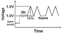
- FIG. 4 is a diagram showing the relationship between time and voltage, representing the triangular wave potential cycle applied in the start / stop durability test.
- the operation method of the fuel cell according to the present invention is as follows: A method of operating a fuel cell comprising a membrane electrode assembly having a cathode, an anode, and an electrolyte membrane disposed between both electrodes,
- the cathode is a cathode provided with a layer containing a specific oxygen reduction catalyst; Supplying an oxidizing agent containing oxygen gas and having a relative humidity of 60% or less at a temperature of the membrane electrode assembly to the cathode;
- a fuel is supplied to the anode.
- the oxygen reduction catalyst used in the method for operating a fuel cell of the present invention contains at least one metal element M1 selected from the group consisting of titanium, niobium, zirconium, tantalum and tin, and each atom of carbon, nitrogen and oxygen,
- the composite particles are contained in the following specific ratio, and primary particles of the compound of the metal element M1 are dispersed in a structure made of carbon.
- the carbon atom content in the composite particles is 0.5 mol or more and 7 mol or less, preferably 1.5 to 6 mol, more preferably 2.5 to 5 mol, with respect to 1 mol of the metal element M1 atom.
- the atom content is greater than 0 mol and less than or equal to 1 mol, preferably 0.01 to 0.4 mol, more preferably 0.02 to 0.2 mol, per 1 mol of metal element M1 atom.
- the content is 1 mol or more and 3 mol or less, preferably 1 to 2.5 mol, more preferably 1.2 to 2.2 mol with respect to 1 mol of metal element M1 atom.
- the oxygen reduction catalyst is hydrophilic, operating a fuel cell including such an oxygen reduction catalyst in the cathode catalyst layer is different from operating a conventional fuel cell using hydrophobic carbon as a catalyst carrier. Because water generated by fuel cell operation (power generation) can be supplied to the solid polymer electrolyte membrane, even when using a low or non-humidified supply gas as a supply gas, compared to using a highly humidified supply gas Therefore, it is considered that the fuel cell can be operated without significantly reducing the voltage.
- the composite particles may further contain a second metal element M2.
- the second metal element M2 is at least one selected from the group consisting of iron, nickel, chromium, cobalt, and manganese. Among these, iron and chromium are preferable, and iron is particularly preferable from the viewpoint of a balance between cost and catalyst performance.
- the content of the metal element M2 is 0.3 mol or less, preferably 0.25 mol or less, more preferably 0.01 to 0.2 mol with respect to 1 mol of the metal element M1. When the content of the metal element M2 is within this range, the performance of the oxygen reduction catalyst is further increased.
- the composite particles have an intensity ratio (D / G ratio, details of the peak intensity of the D band to the peak intensity of the G band in a Raman spectrum (a spectrum obtained by performing Raman spectroscopy measurement of the composite particle).
- D / G ratio details of the peak intensity of the D band to the peak intensity of the G band in a Raman spectrum (a spectrum obtained by performing Raman spectroscopy measurement of the composite particle).
- D / G ratio details of the peak intensity of the D band to the peak intensity of the G band in a Raman spectrum (a spectrum obtained by performing Raman spectroscopy measurement of the composite particle).
- D / G ratio details of the peak intensity of the D band to the peak intensity of the G band in a Raman spectrum (a spectrum obtained by performing Raman spectroscopy measurement of the composite particle).
- Raman spectrum a spectrum obtained by performing Raman spectroscopy measurement of the composite particle.
- the voltage drop can be further suppressed, and the voltage drop when the fuel cell is repeatedly started and stopped is small (hereinafter also
- the composite particles having such an XRD pattern have rutile type titanium oxide as a main phase.
- the voltage drop is further suppressed compared to the case where a high-humidity oxidant gas is used. And good start-stop durability is shown.
- the metal element M1 is titanium
- the valence of titanium in the composite particles determined by X-ray absorption near edge structure (XANES) analysis is greater than 3 and less than 4.
- XANES X-ray absorption near edge structure
- the composite particles are particles in which the primary particles of the compound of the metal element M1 are dispersed in a structure made of carbon.
- the central metal M1 is obtained by thermal decomposition of a precursor that is highly dispersed in an organic compound that becomes a carbon source and a nitrogen source. This is considered to be because composite particles in which primary particles are highly dispersed in a structure made of carbon are obtained.
- the specific surface area calculated by the BET method of the composite particles is preferably 100 m 2 / g or more, more preferably 100 to 600 m 2 / g, still more preferably 150 to 600 m 2 / g.
- the composite particles containing the metal element M1, carbon, nitrogen, and oxygen atoms in a specific ratio and in which the primary particles of the compound of the metal element M1 are dispersed in a structure made of carbon include, for example, the metal element M1.
- a mixture of a compound containing nitrogen hereinafter also referred to as “M1-containing compound (1)” and a nitrogen-containing organic compound (2) (however, of the M1-containing compound (1) and the nitrogen-containing organic compound (2)) At least one of which has an oxygen atom) can be produced by subjecting it to heat treatment and oxidation treatment.
- the mixture is preferably Step 1 of mixing the M1-containing compound (1), the nitrogen-containing organic compound (2) and a solvent to obtain a catalyst precursor solution, and removing the solvent from the catalyst precursor solution to obtain a solid residue (that is, the mixture) Step 2 of obtaining It is manufactured through.
- the composite particles are, for example, M1 containing compound (1), nitrogen containing organic compound (2) (however, at least one of said M1 containing compound (1) and said nitrogen containing organic compound (2) has an oxygen atom) and a solvent are mixed.
- Step 1 for obtaining a catalyst precursor solution Step 2 for removing the solvent from the catalyst precursor solution to obtain a solid residue, and Step 3 for heat treating the solid residue at a temperature of 500 to 1400 ° C. to obtain a heat-treated product.
- Step 1 for obtaining a catalyst precursor solution
- Step 2 for removing the solvent from the catalyst precursor solution to obtain a solid residue
- Step 3 for heat treating the solid residue at a temperature of 500 to 1400 ° C. to obtain a heat-treated product.
- step 1 at least M1-containing compound (1), nitrogen-containing organic compound (2) (however, at least one of M1-containing compound (1) and nitrogen-containing organic compound (2) has an oxygen atom) and A solvent is mixed to obtain a catalyst precursor solution.
- the compound further containing the second metal element M2 is at least one metal element M2 selected from iron, nickel, chromium, cobalt, and manganese. May be added to the catalyst precursor solution (hereinafter also referred to as “M2-containing compound (3)”). The order of adding these materials is not particularly limited.
- mixing is preferably carried out while stirring the solvent.
- the said compound when the said compound is hard to melt
- the mixture when heat is rapidly generated during mixing, the mixture is mixed while cooling or mixed little by little.
- the M1-containing compound (1) preferably has at least one selected from an oxygen atom and a halogen atom.
- the M1-containing compound (1) include a complex of the metal element M1, and a phosphate, sulfate, nitrate, organic acid salt, acid halide (halide hydrolyzate), alkoxide of the metal element M1, Examples thereof include esters, halides, perhalogenates and hypohalites, more preferably alkoxides, esters, acetylacetone complexes, chlorides, bromides, iodides, acid chlorides, acid bromides, acid iodides of the metal element M1. And sulfates. More preferably, an alkoxide or an acetylacetone complex is mentioned from a soluble viewpoint to the solvent in the said liquid phase. These may be used alone or in combination of two or more.
- M1-containing compound (1) examples include Titanium tetramethoxide, titanium tetraethoxide, titanium tetrapropoxide, titanium tetraisopropoxide, titanium tetrabutoxide, titanium tetraisobutoxide, titanium tetrapentoxide, titanium tetraacetylacetonate, titaniumoxydiacetylacetonate, tris (acetyl Acetonato) titanium chloride ([Ti (acac) 3 ] 2 [TiCl 6 ]) (acac represents acetylacetonate ion, the same shall apply hereinafter), titanium tetrachloride, titanium trichloride, oxychloride Titanium compounds such as titanium, titanium tetrabromide, titanium tribromide, titanium oxybromide, titanium tetraiodide, titanium triiodide, titanium oxyiodide; Niobium pentamethoxide,
- the nitrogen-containing organic compound (2) is preferably a compound that can be a ligand capable of coordinating to the M1 atom in the M1-containing compound (1), and is a multidentate ligand (preferably a bidentate ligand or More preferred are compounds capable of forming a tridentate ligand (which can form a chelate).
- Nitrogen-containing organic compound (2) may be used alone or in combination of two or more.
- the nitrogen-containing organic compound (2) is preferably an amino group, nitrile group, imide group, imine group, nitro group, amide group, azide group, aziridine group, azo group, isocyanato group, isothiocyanate group, oxime group, diazo group.
- a functional group such as a nitroso group, or a ring such as a pyrrole ring, a porphyrin ring, an imidazole ring, a pyridine ring, a pyrimidine ring, or a pyrazine ring (these functional groups and rings are also collectively referred to as “nitrogen-containing molecular groups”).
- the nitrogen-containing organic compound (2) has a nitrogen-containing molecular group in the molecule, the nitrogen-containing organic compound (2) can be strongly coordinated with the atoms of the metal element M1 derived from the M1-containing compound (1) through the mixing in Step 1. it is conceivable that.
- an amino group, an imine group, an amide group, a pyrrole ring, a pyridine ring and a pyrazine ring are more preferable, an amino group, an imine group, a pyrrole ring and a pyrazine ring are more preferable, and an amino group and a pyrazine ring are preferable.
- an amino group, an imine group, a pyrrole ring and a pyrazine ring are more preferable, and an amino group and a pyrazine ring are preferable.
- Is particularly preferable because the activity of the resulting oxygen reduction catalyst is particularly high.
- the nitrogen-containing organic compound (2) is preferably a hydroxyl group, a carboxyl group, a formyl group, a halocarbonyl group, a sulfonic acid group, a phosphoric acid group, a ketone group, an ether group or an ester group. ").
- the nitrogen-containing organic compound (2) has an oxygen-containing molecular group in the molecule, it is considered that the nitrogen-containing organic compound (2) can be strongly coordinated by the atoms of the metal element M1 derived from the M1-containing compound (1) through the mixing in Step 1. .
- a carboxyl group and a formyl group are particularly preferable because the activity of the obtained oxygen reduction catalyst is particularly high.
- amino acids having an amino group and a carboxyl group, and derivatives thereof are preferable.
- amino acids examples include alanine, arginine, asparagine, aspartic acid, cysteine, glutamine, glutamic acid, glycine, histidine, isoleucine, leucine, lysine, methionine, phenylalanine, serine, threonine, tryptophan, tyrosine, valine, norvaline, glycylglycine, Triglycine and tetraglycine are preferable.
- acylpyrroles such as acetylpyrrole, pyrrolecarboxylic acid, acylimidazoles such as acetylimidazole, carbonyldiimidazole, imidazolecarboxylic acid, pyrazole, acetanilide, pyrazinecarboxylic acid Piperidinecarboxylic acid, piperazinecarboxylic acid, morpholine, pyrimidinecarboxylic acid, nicotinic acid, 2-pyridinecarboxylic acid , 2,4-pyridinedicarboxylic acid, 8-quinolinol, and polyvinylpyrrolidone, and the resulting oxygen reduction catalyst has a high activity, so that it can be a bidentate ligand, specifically pyrrole-2-carboxylic acid.
- Acid imidazole-4-carboxylic acid, 2-pyrazinecarboxylic acid, 2-piperidinecarboxylic acid, 2-piperazinecarboxylic acid, nicotinic acid, 2-pyridinecarboxylic acid, 2,4-pyridinedicarboxylic acid, and 8-quinolinol are preferred. .
- alanine, glycine, lysine, methionine, tyrosine, 2-pyrazinecarboxylic acid, and 2-pyridinecarboxylic acid are more preferable.
- the nitrogen-containing organic used in Step 1 with respect to the number A of atoms of the metal element M1 of the M1-containing compound (1) used in Step 1
- the ratio (B / A) of the total number of carbon atoms B in the compound (2) is preferably 2 to 200, more preferably 3 to 100, and still more preferably 5 to 50.
- the nitrogen-containing organic used in Step 1 with respect to the number A of atoms of the metal element M1 of the M1-containing compound (1) used in Step 1
- the ratio (C / A) of the total number of nitrogen atoms C in the compound (2) is preferably 1 to 28, more preferably 2 to 17, and still more preferably 3 to 12.
- M2-containing compound (3) Specific examples of the M2-containing compound (3) include Iron (II) chloride, iron (III) chloride, iron (III) sulfate, iron (II) sulfide, iron (III) sulfide, potassium ferrocyanide, potassium ferricyanide, ammonium ferrocyanide, ammonium ferricyanide, iron ferrocyanide , Iron (II) nitrate, iron (III) nitrate, iron (II) oxalate, iron (III) oxalate, iron (II) phosphate, iron (III) phosphate ferrocene, iron (II) hydroxide, water Iron (III) oxide, iron (II) oxide, iron (III) oxide, triiron tetroxide, iron (II) ethylenediaminetetraacetate, iron (II) acetate, iron (II) lactate, iron (III) citrate Iron compounds such as; Nickel chloride (II), nickel sulfate (I
- solvent examples include water, acetic acid, acetylacetone, alcohols, and a mixed solvent thereof.
- alcohols ethanol, methanol, butanol, propanol and ethoxyethanol are preferable, and ethanol and methanol are more preferable.
- acid acetic acid, nitric acid, hydrochloric acid, phosphoric acid and citric acid are preferable, and acetic acid and nitric acid are more preferable. These may be used alone or in combination of two or more.
- step 2 the solvent is removed from the catalyst precursor solution obtained in step 1 to obtain a solid residue.
- the method for removing the solvent is not particularly limited, and examples thereof include a method using a spray dryer or a rotary evaporator.
- the composition or aggregated state of the solid residue obtained in Step 2 may be non-uniform.
- composite particles having a more uniform particle size can be obtained by mixing and crushing the solid residue and using a more uniform and fine powder in Step 3.
- step 3 the solid residue obtained in step 2 is heat-treated to obtain a heat-treated product.
- the temperature at the time of this heat treatment is, for example, 500 to 1400 ° C., preferably 700 to 1400 ° C., more preferably 800 to 1300 ° C.
- the metal element M1 is titanium
- a temperature of 700 ° C. or higher is necessary in order to use rutile titanium oxide as the main phase in the composite particles.
- it exceeds 1400 degreeC it will become difficult to make content of carbon, nitrogen, and oxygen in a composite particle into the said range.
- Examples of the heat treatment method include a stationary method, a stirring method, a dropping method, and a powder trapping method.
- the rate of temperature rise is not particularly limited, but is preferably about 1 ° C./min to 100 ° C./min, more preferably 5 ° C./min to 50 ° C./min. is there.
- the heating time is preferably 0.1 to 10 hours, more preferably 0.5 to 5 hours, and further preferably 0.5 to 3 hours.
- the heating time is 0.1 to 10 hours, preferably 0.5 to 5 hours.
- the heating time of the solid residue is usually 0.1 to 5 hours, preferably 0.5 to 2 hours.
- the average residence time calculated from the steady sample flow rate in the furnace is set as the heating time.
- the heating time of the solid residue is usually 0.5 to 10 minutes, preferably 0.5 to 3 minutes.
- the heating time is within the above range, uniform heat-treated particles tend to be formed.
- the heating time of the solid residue is 0.2 seconds to 1 minute, preferably 0.2 to 10 seconds.
- the heating time is within the above range, uniform heat-treated particles tend to be formed.
- an infrared furnace such as an electric furnace using electricity as a heat source or an infrared gold image furnace capable of strict temperature control.
- the atmosphere during the heat treatment is preferably a non-oxidizing atmosphere so that the content of each constituent element of the composite particles can be easily within the above range.
- the main component is preferably a non-oxidizing gas atmosphere.
- non-oxidizing gases nitrogen gas, argon gas, helium gas, and hydrogen gas are preferable because they are relatively inexpensive and easily available, and nitrogen gas and argon gas are more preferable. Mixing of these gases and hydrogen gas is preferable. Gas is more preferred.
- These non-oxidizing gases may be used alone or in combination of two or more.
- the concentration of hydrogen gas is, for example, 100% by volume or less, preferably 1 to 20% by volume, more preferably 1 to 5% by volume.
- the heat-treated product obtained by the heat treatment may be used as it is in the next step, or may be used in the next step after further crushing.
- operations for making the heat-treated product fine such as crushing and crushing, are referred to as “crushing” without any particular distinction.
- crushing for example, a roll rolling mill, a ball mill, a small-diameter ball mill (bead mill), a medium stirring mill, an airflow grinder, a mortar, an automatic kneading mortar, a tank disintegrator, or a jet mill can be used.
- the manufacturing method preferably includes a step 4 in which the heat-treated product obtained in the step 3 is subjected to an oxidation treatment with an oxidizing agent that donates oxygen atoms.
- the degree of oxidation treatment in step 4 is adjusted so that the D / G ratio of the composite particles is in the range of 0.4 to 1.0.
- Examples of the oxidizing agent that donates oxygen atoms include hydrogen peroxide, perchloric acid, peracetic acid, and water vapor.
- the D / G ratio can be set within the above range by adjusting the degree of oxidation. Oxidation can reduce the D / G ratio, but excessive oxidation treatment increases the D / G ratio.
- step 4 it is preferable to obtain an oxidation condition for making it within the range of the D / G ratio by a preliminary experiment.
- the degree of oxidation can be adjusted by appropriately selecting the type of oxidant, the amount of oxidant, the oxidation treatment temperature, the oxidation treatment time, and the like. In particular, the adjustment of the oxidation treatment temperature is important. Further, when the M2-containing compound (3) (particularly an iron compound) is used in Step 1, the D / G ratio tends to decrease.
- Step 4 may be carried out after completion of Step 3, that is, after the heat-treated product is cooled to a temperature lower than 100 ° C., preferably 10 to 50 ° C. near room temperature (hereinafter, this embodiment is referred to as “ Also referred to as “Aspect 1”).
- step 4 may be performed overlapping with step 3 (hereinafter, this embodiment is also referred to as “aspect 2”). That is, in step 3, oxidation treatment with an oxidizing agent that donates oxygen atoms may be performed simultaneously with or after the start of the heat treatment of the solid residue. In this case, strictly speaking, there is a possibility that not the oxidation treatment of the heat treated product but the solid residue oxidation treatment, but here, for convenience, any oxidation treatment is regarded as the oxidation treatment of the heat treated product.
- water vapor is preferably used as the oxidizing agent.
- Embodiment 2 can be carried out by mixing water vapor into the atmospheric gas in step 3 if water vapor is used as the oxidizing agent.
- the amount of water vapor to be mixed is not particularly limited as long as the oxidation treatment proceeds, but it is preferable that the amount of water vapor is included in the atmospheric gas into which the saturated water vapor amount at 0 ° C. to 50 ° C. is introduced for easy handling.
- step 4 may be continued (hereinafter, this embodiment is also referred to as “aspect 3”).
- the D / G ratio of the composite particles is not necessarily in the range of 0.4 to 1.0.
- step 4 after the end of step 3 is performed. (Hereinafter also referred to as “Step 4a”), the D / G ratio of the composite particles may be adjusted to be in the range of 0.4 to 1.0.
- the temperature condition of the process 4a is the same as the temperature condition of the said aspect 1.
- oxidizing agent used in step 4a at least one selected from hydrogen peroxide, perchloric acid and peracetic acid is preferable because it is easy to handle.
- Mode 3 has the advantage that the D / G ratio can be easily adjusted as compared with Mode 2 because Step 4 is performed in two stages as described above.
- step of crushing the heat-treated product as described above may be provided between step 3 and step 4a.
- the oxygen reduction catalyst includes particles (hereinafter also referred to as “noble metal particles”) comprising the composite particles and further comprising a noble metal element or an alloy thereof (hereinafter also referred to as “noble metal etc.”) supported on the composite particles.
- the containing catalyst (hereinafter also referred to as “composite catalyst”) is preferable.
- the oxygen reduction catalyst is the composite catalyst, the fuel cell can be operated at a high initial voltage using a low humidified or non-humidified oxidant gas.
- the noble metal element examples include at least one selected from the group consisting of platinum, gold, palladium, iridium, rhodium and ruthenium. Among these, platinum, palladium and iridium are preferable, and platinum is more preferable.
- the noble metal element alloy examples include the alloy of the noble metal elements, and the noble metal element and at least one metal element selected from the group consisting of iron, nickel, chromium, cobalt, titanium, copper, vanadium, and manganese. And alloys thereof. Among these, an alloy of platinum and at least one selected from the group consisting of iron, cobalt, and nickel is particularly preferable.
- the content of the noble metal particles in the composite catalyst is preferably 5 to 50% by mass, more preferably 20 to 40% by mass.
- the fuel cell can be operated at a higher initial voltage by using a low humidified or non-humidified oxidant gas.
- the method for supporting these noble metals and the like is not particularly limited as long as they can be supported for practical use, but a method for supporting noble metals or the like using a precursor such as a noble metal is preferable.
- a precursor such as a noble metal is a substance that can be converted into the noble metal by a predetermined treatment, and specific examples thereof include chloroplatinic acid, iridium chloride, palladium chloride, and a mixture thereof.
- the method for supporting the precursor such as noble metal on the composite particles is not particularly limited, and a method using a conventionally known catalyst metal supporting technology can be used.
- a method comprising a step of dispersing composite particles in a precursor solution such as a noble metal and evaporating to dryness, followed by a step of applying a heat treatment,
- a method comprising a step of supporting a noble metal or the like on a composite particle by dispersing the composite particle in a precursor colloid solution such as a noble metal and adsorbing a precursor colloid such as a noble metal on the composite particle,
- a metal oxide, a hydrous oxide, and a metal hydroxide are obtained at the same time. Examples include a method including a step of adsorbing the composite particles, a step of reducing them, and a step of heat-treating them as necessary.
- a fuel cell used in the present invention includes a membrane electrode assembly including a cathode including a layer (cathode catalyst layer) containing the oxygen reduction catalyst, an anode, and an electrolyte membrane disposed between both electrodes. Yes.
- the anode layer includes a catalyst layer (anode catalyst layer), and the anode catalyst layer includes a conventionally known anode catalyst layer (for example, a catalyst layer containing a platinum-supported carbon catalyst) and a catalyst containing the oxygen reduction catalyst. Layer.
- the cathode and the anode catalyst layer include an oxygen reduction catalyst and a polymer electrolyte.
- the catalyst layer may further include electron conductive particles.
- the material of the electron conductive particles examples include carbon, a conductive polymer, a conductive ceramic, a metal, or a conductive inorganic oxide such as tungsten oxide or iridium oxide, which can be used alone or in combination. .
- the electron conductive particles made of carbon have a large specific surface area, and are easily available with a small particle size at low cost and excellent in chemical resistance, carbon alone or carbon and other electron conductive particles can be used. Mixtures are preferred.
- Examples of carbon include carbon black, graphite, activated carbon, carbon nanotube, carbon nanofiber, carbon nanohorn, fullerene, porous carbon, and graphene. If the particle size of the electron conductive particles made of carbon is too small, it becomes difficult to form an electron conduction path, and if it is too large, the gas diffusibility of the catalyst layer and the catalyst utilization rate tend to decrease.
- the thickness is preferably 10 to 1000 nm, more preferably 10 to 100 nm.
- the mass ratio of the oxygen reduction catalyst to the electron conductive particles is preferably 1: 1 to 100: 1.
- the catalyst layer usually contains a polymer electrolyte.
- the polymer electrolyte is not particularly limited as long as it is generally used in a fuel cell catalyst layer.
- a perfluorocarbon polymer having a sulfonic acid group for example, NAFION (registered trademark)
- a hydrocarbon polymer compound having a sulfonic acid group a polymer doped with an inorganic acid such as phosphoric acid.
- Nafion is preferable.
- a 5% Nafion solution DE521, manufactured by DuPont
- the method for forming the catalyst layer is not particularly limited.
- the coating method include a dipping method, a screen printing method, a roll coating method, a spray method, and a bar coater coating method.
- a method of forming a catalyst layer on an electrolyte membrane by a transfer method after forming a catalyst layer on a base material by a coating method or a filtration method from a suspension obtained by dispersing the constituent materials of the catalyst layer in a solvent can be mentioned. .
- Electrode The electrodes (cathode and anode) are composed of a catalyst layer and a gas diffusion layer (hereinafter also referred to as “GDL”).
- GDL gas diffusion layer
- the gas diffusion layer is a porous layer that assists gas diffusion.
- the gas diffusion layer may be anything as long as it has electron conductivity, high gas diffusibility, and high corrosion resistance.
- carbon-based porous materials such as carbon paper and carbon cloth are used. Materials and aluminum foil coated with stainless steel and corrosion-resistant materials for weight reduction are used.
- the membrane electrode assembly is composed of a cathode catalyst layer, an anode catalyst layer, and a polymer electrolyte membrane disposed between these catalyst layers.
- the membrane electrode assembly may have a gas diffusion layer.
- polymer electrolyte membrane for example, a polymer electrolyte membrane using a perfluorosulfonic acid polymer or a polymer electrolyte membrane using a hydrocarbon polymer is generally used.
- a membrane impregnated with a liquid electrolyte or a membrane filled with a polymer electrolyte in a porous body may be used.
- the cathode catalyst layer and the anode catalyst layer are sandwiched between the two surfaces of the electrolyte membrane with the gas diffusion layer. You can get it.
- the fuel cell may be provided in an article having at least one function selected from the group consisting of a power generation function, a light emission function, a heat generation function, a sound generation function, an exercise function, a display function, and a charging function.
- the article that can include the fuel cell include buildings, houses, buildings such as tents, fluorescent lamps, LEDs, etc., organic EL, street lamps, indoor lighting, lighting fixtures such as traffic lights, machines, vehicles themselves Equipment including automobile equipment, home appliances, agricultural equipment, electronic equipment, mobile phones, etc., sanitary equipment such as beauty equipment, portable tools, bathroom accessories, furniture, toys, decorations, bulletin boards, coolers
- Examples include outdoor supplies such as boxes, outdoor generators, teaching materials, artificial flowers, objects, power supplies for cardiac pacemakers, and power supplies for heating and cooling devices equipped with Peltier elements.
- a fuel cell operation method is a fuel cell operation method including a membrane electrode assembly having a cathode, an anode, and an electrolyte membrane disposed between both electrodes,
- the cathode is a cathode provided with a layer containing the oxygen reduction catalyst; Supplying an oxidant gas containing oxygen gas and having a relative humidity at the temperature of the membrane electrode assembly of 60% or less to the cathode; A fuel gas is supplied to the anode.
- the fuel cell while supplying a low-humidity oxidant gas to the cathode, the fuel cell is operated and power is generated without significantly reducing the voltage compared to the case of using a high-humidity supply gas. Can do.
- a power generator (fuel cell system) according to the present invention includes a membrane electrode assembly having a cathode, an anode, and an electrolyte membrane disposed between both electrodes.
- the fuel cell includes oxygen gas in the cathode.
- the means for supplying the oxidant gas may include a humidifier for humidifying the oxidant gas.
- the means for supplying the fuel gas may include a humidifier for humidifying the fuel gas. Any means may not include a humidifier.
- an oxidant gas usually used for solid polymer fuel cells such as air and oxygen can be used, and as the fuel gas, it is usually used for solid polymer fuel cells such as hydrogen gas.
- the fuel gas used can be used. Further, liquid fuel such as methanol may be used as the fuel.
- the humidity of the oxidant gas (relative humidity at the temperature of the membrane electrode assembly) is 60% or less, or 30% or less or 0%.
- the humidity adjustment method may be any method as long as the desired amount of gaseous water can be included in the oxidant gas or fuel gas.
- the oxidant gas is passed through a water tank of a humidifier maintained at a constant temperature.
- the humidity may be adjusted by adjusting the humidifier temperature.
- the anode is an anode having a layer containing the oxygen reduction catalyst, the voltage is remarkably higher than that in the case of using a high-humidity supply gas while supplying a low-humidity fuel gas to the anode.
- the fuel cell can be operated and generated without being reduced.
- the humidity of the fuel gas may be 60% or less, 45% or less, or 0%.
- the use of a gas with a humidity of 0% is preferable in that a humidifier for humidifying the supply gas is not required, and the power generation device (fuel cell system) can be downsized.
- Elemental analysis carbon About 0.1 g of a sample was weighed and measured with EMIA-110 manufactured by Horiba.
- Nitrogen / oxygen About 0.1 g of a sample was weighed and sealed in Ni-Cup, and then measured with a TC600 manufactured by LECO.
- Transition metal element titanium, etc.: About 0.1 g of a sample was weighed into a platinum dish, and acid was added for thermal decomposition. This heat-decomposed product was fixed, diluted appropriately, and quantified using ICP-OES (VISA-PRO from SII) or ICP-MS (HP7500 from Agilent).
- ICP-OES VISA-PRO from SII
- ICP-MS HP7500 from Agilent
- Powder X-ray diffraction measurement The powder X-ray diffraction of the sample was measured using X'Pert MPD manufactured by PANalytical. Cu-K ⁇ was used as the X-ray light source.
- the diffraction line peak in the powder X-ray diffraction of each sample was counted by regarding a signal that can be detected with a signal (S) to noise (N) ratio (S / N) of 2 or more as one peak.
- the noise (N) is the width of the baseline.
- Raman spectroscopic measurement Microscopic Raman measurement was performed using NRS-5100 manufactured by JASCO Corporation. Prior to sample measurement, the apparatus was calibrated using a reference silicon substrate. Sample measurement was performed in a lattice measurement mode, with nine measurements taken once, and a total of 5 measurements (total 45 locations) at different sample positions. The spectra obtained from each measurement were averaged to obtain the final result. The excitation wavelength was 532 nm, and the exposure time and integration number were 3 seconds and 5 times for each laser irradiation point.
- the obtained spectrum was analyzed using Spectra Manager Version 2 manufactured by JASCO. That is, after appropriate baseline correction, the 850 ⁇ 2000 cm -1 region of the spectrum, peak fitting with 1340cm -1, 1365cm -1, 1580cm -1 , 4 single Lorentz function with maximum at 1610 cm -1 did.
- the intensity ratio between the resulting peak at 1340 cm ⁇ 1 (D band) and the peak at 1580 cm ⁇ 1 (G band) was calculated as the D / G ratio.
- X-ray absorption spectroscopy (XAS) measurement Using a large synchrotron radiation facility in Harima Science Park City, Hyogo Prefecture, commonly known as “SPring-8”, measurement was performed under the conditions described in [0075] of JP2011-240242. It was. Specifically, it is as follows.
- the temperature of the water bath was set to about 80 ° C., and the solvent was slowly evaporated while heating and stirring the catalyst precursor solution.
- the solid residue obtained by completely evaporating the solvent was finely and uniformly crushed with a mortar to obtain a powder (1a).
- This powder (1a) was introduced into a tubular furnace and introduced through a bubbler containing distilled water kept at 25 ° C., and a saturated amount of water vapor at 25 ° C. containing 4% by volume of hydrogen gas and nitrogen gas, In the mixed gas atmosphere, the temperature inside the furnace was increased to 880 ° C. at a temperature increase rate of 20 ° C./min and heat-treated at 880 ° C. for 1 hour. The heat-treated powder was allowed to cool to room temperature, ground in isopropanol using a planetary ball mill, filtered, and dried to obtain powder (1b).
- composite catalyst (1) a catalyst containing 20% by mass of platinum (hereinafter also referred to as “composite catalyst (1)”) was obtained.
- This powder (1a) was put into a tubular furnace and heated in a furnace in a mixed gas atmosphere of hydrogen gas containing 4% by volume of hydrogen gas and nitrogen gas introduced without passing through a bubbler containing distilled water.
- the temperature was raised to 900 ° C. at a rate of 10 ° C./min, and heat treatment was performed at 900 ° C. for 1 hour.
- the heat-treated powder was allowed to cool to room temperature, pulverized in isopropanol using a planetary ball mill, filtered, and dried to obtain powder (4b).
- Operation 4-3 A composite catalyst (4) was obtained in the same manner as in Operation 1-3 of Production Example 1, except that the platinum-supporting operation catalyst (1) was changed to 1.00 g of the catalyst (4).
- a composite catalyst (5) was obtained by carrying out the same operations as in Operation 1-3 of Production Example 1, except that the catalyst (1) was changed to 1.00 g of the catalyst (5).
- a composite catalyst (8) was obtained by performing the same operation as in operation 1-3 of Production Example 1, except that the catalyst (1) was changed to 1.00 g of catalyst (8).
- a composite catalyst (12) was obtained by performing the same operation as in Operation 1-3 of Production Example 1, except that the catalyst (1) was changed to 1.00 g of the catalyst (12).
- a composite catalyst (13) was obtained by carrying out the same operations as in Operation 1-3 of Production Example 1, except that the catalyst (1) was changed to 1.00 g of the catalyst (13).
- a composite catalyst (14) was obtained by performing the same operation as in operation 1-3 of Production Example 1, except that the catalyst (1) was changed to 1.00 g of the catalyst (14).
- This powder (18a) was introduced into a tubular furnace and introduced without passing through a bubbler containing distilled water, mixed gas atmosphere containing 1% by volume of oxygen gas, 4% by volume of hydrogen gas, and the balance being nitrogen gas The temperature was raised below and heat treated at 1000 ° C. for 10 hours to obtain a powder (hereinafter also referred to as “catalyst (18)”).
- a composite catalyst (18) was obtained by carrying out the same operations as in Operation 1-3 of Production Example 1, except that the catalyst (1) was changed to 1.00 g of the catalyst (18).
- the catalyst containing 5% by mass of platinum and the platinum-supported carbon catalyst (TEC10E50E) manufactured by Tanaka Kikinzoku Kogyo Co., Ltd. are mixed at a ratio of 6: 4 to contain 21.6% by mass of platinum.
- a catalyst composition (hereinafter also referred to as “mixed catalyst (23)”) was obtained.
- a catalyst containing 20% by mass of platinum (hereinafter referred to as “composite”) was obtained by performing the same operation as in Operation 1-3 of Production Example 1 except that the catalyst (1) was changed to 1.00 g of the catalyst (24). Catalyst (24) ") was obtained.
- Titanium tetrachloride (manufactured by Junsei Chemical Co., Ltd.) is supplied to the heating tube set at 160 ° C. at 6 g / hour, nitrogen gas is further supplied at 1 L / minute, and a mixed gas (a) of titanium tetrachloride gas and nitrogen gas is supplied. Obtained. This mixed gas (a) was supplied to the reactor as indicated by reference numeral 2 in FIG.
- Water was supplied at a rate of 0.1 g / hour to a heating tube set at 120 ° C., and nitrogen gas was further supplied at 100 mL / min to obtain a mixed gas (b) of water vapor and nitrogen gas.
- FIG. 1 shows a mixed gas (c) of a mixed gas obtained by diluting ammonia gas 6 kg standard cc / min (hereinafter referred to as “sccm”) and methane gas 60 sccm with nitrogen gas at 100 mL / min and the mixed gas (b).
- sccm a mixed gas obtained by diluting ammonia gas 6 kg standard cc / min
- methane gas 60 sccm with nitrogen gas at 100 mL / min and the mixed gas (b).
- a catalyst containing 20% by mass of platinum (hereinafter referred to as “composite”) was obtained by performing the same operation as in Operation 1-3 of Production Example 1 except that the catalyst (1) was changed to 1.00 g of the catalyst (25). Catalyst (25) ”) was obtained.
- “5” is a primary particle of the titanium compound
- “6” is graphite-like carbon
- “7” is amorphous-like carbon.
- primary particles of the titanium compound were observed along with the graphite-like or amorphous-like carbon structure in any catalyst.
- secondary aggregation of the titanium compound primary particles was not observed, and it was confirmed that the titanium compound primary particles were dispersed in the carbon structure.
- the amorphous-like carbon was decreased as compared with the catalyst (13), and the graphite-like carbon was observed more clearly.
- X-ray absorption spectroscopy [X-ray absorption spectroscopy] X-ray absorption spectroscopy (XAS) measurement was performed on the catalyst (1) and the catalysts (4) to (8).
- the threshold value for X-ray absorption is that of a standard sample measured as a reference system, TiO 2 (titanium valence 4) and Ti 2 O 3 (titanium valence 3). The value was between. From this, the valence of titanium contained in the catalyst (1), the catalyst (4) to the catalyst (8) was estimated to be more than 3 and less than 4.
- the number of the cathode ink matches the number of the composite catalyst used. The same applies to the following.
- Cathode ink except that the composite catalyst (9) or (24) was used instead of the composite catalyst (1), and the amounts of the catalyst, 5% aqueous Nafion solution, pure water and isopanol were changed as shown in Table 3.
- the same operations as in the preparation of (1) were performed, and cathode inks (9) and (24) having different composite catalyst amounts per unit area as shown in Table 3 were prepared.
- Cathode inks (4) to (8), (12) to (22), and (25) having different catalyst amounts as shown in Table 3 were prepared.
- the immersion material was dried at room temperature and then heated at 350 ° C. for 1 hour, whereby PTFE was dispersed inside the carbon paper to obtain a cathode GDL having water repellency.
- the cathode GDL was used in a size of 5 cm ⁇ 5 cm.
- the cathode ink (1) is applied to the surface of the cathode GDL at 80 ° C. by an automatic spray coating apparatus (manufactured by Sanei Tech Co., Ltd.), so that the amount of the composite catalyst (1) per unit area is increased.
- a cathode (1) having a cathode catalyst layer of 0.500 mg / cm 2 on the cathode GDL surface was produced.
- the catalyst per unit area was obtained by performing the same operation as that for the cathode (1) except that any one of the cathode inks (2) to (25) was used instead of the cathode ink (1).
- Cathodes (2) to (25) having different amounts as shown in Table 3 were prepared.
- the amount of noble metal per unit area in each of the cathodes was 0.1 mg / cm 2 .
- the immersed material was dried at room temperature and then heated at 350 ° C. for 1 hour, whereby PTFE was dispersed inside the carbon paper to obtain an anode GDL having water repellency.
- anode-supported carbon catalyst is applied to the surface of the anode GDL having a size of 5 cm ⁇ 5 cm by applying the anode ink (1) at 80 ° C. with an automatic spray coating apparatus (manufactured by Saneitec Co., Ltd.).
- An electrode having an anode catalyst layer on the surface of the anode GDL (hereinafter also referred to as “anode (1)”) having an amount of 1.00 mg / cm 2 per unit area was produced.
- a fuel cell membrane electrode assembly (hereinafter also referred to as “MEA”) in which the electrolyte membrane is disposed between a cathode and an anode was fabricated as follows.
- An electrolyte membrane (Nafion membrane (NR-212, manufactured by DuPont)) is sandwiched between the cathode (1) and the anode (1), and a hot press machine is used so that the cathode catalyst layer and the anode catalyst layer are in close contact with the electrolyte membrane. These were thermocompression bonded at a temperature of 140 ° C. and a pressure of 1 MPa for 7 minutes to prepare MEA (1).
- the cathode (1) was changed from the cathode (2) to the cathode (25), and MEA (2) to MEA (25) were produced in the same manner as described above.
- Single cell production MEA (1) produced in 5 above is sandwiched between two sealing materials (gaskets), two gas channel separators, two current collector plates and two rubber heaters, and fixed with bolts. Was tightened to a predetermined surface pressure (0.8 Pa) to produce a single cell of a polymer electrolyte fuel cell (hereinafter also referred to as “single cell (1)”) (cell area: 5 cm 2 ).
- MEA (1) was changed to MEA (2) to MEA (25), and single cells (2) to single cells (25) were produced in the same manner as described above.
- the composite catalysts (1) to (8), (12) to (22), and (25) were judged to be hydrophilic by the above test.
- Example 1 Operation of fuel cell
- Example 1 Operation of the fuel cell at low humidity After the temperature of the single cell (1) is adjusted to 80 ° C. and the anode humidifier to 60 ° C., hydrogen gas having a relative humidity (RH) of about 45% is supplied to the anode as fuel. It supplied through the humidifier, and air (dry air) was supplied to the cathode side without passing through the humidifier.
- RH relative humidity
- a fuel cell (single cell (1)) is operated under conditions of an oxygen effective utilization rate of 40% and a hydrogen gas effective utilization rate of 10% or more, and a constant current coulometric measurement is performed at a current density of 0.3 A / cm 2 .
- the ratio of the voltage value when dry air is used to the voltage value when air having a relative humidity (RH) of 100% is used (hereinafter referred to as “voltage ratio (low humidification / high humidification)”).
- Tables 4 and 5 show.
- the voltage value when air with a relative humidity (RH) of 100% is used is the “initial voltage” value of the current-voltage (IV) characteristic measured in the start / stop durability test described later. Adopted.
- the high voltage ratio is different from that when the mixed catalyst (23) is used. (Low humidification / high humidification) was obtained. This is because, in the mixed catalyst (23), the TiO 2 site and the carbon site serving as the hydrophilic portion are not uniformly dispersed in the catalyst layer, whereas the composite catalyst (1) to (8) and the composite catalyst are used. In the catalysts (12) to (17), the primary particles of the compound of the metal element M1 are highly dispersed in the carbon structure, which causes the difference in the voltage ratio (low humidification / high humidification). I guess that.
- a plurality of types of particles having different properties such as a mixed catalyst (23) (for example, inorganic particles having high specific gravity and hydrophilicity and carbon particles having low specific gravity and low hydrophilicity such as titanium oxide) are mixed uniformly. It is known that it is technically difficult to form a film.
- a mixed catalyst (23) for example, inorganic particles having high specific gravity and hydrophilicity and carbon particles having low specific gravity and low hydrophilicity such as titanium oxide
- start / Stop Durability Test A start / stop durability test was performed on the composite catalyst that showed power generation performance in the results of the operation test of the fuel cell at the low humidity.
- the temperature of the single cell (1) was adjusted to 80 ° C., the anode humidifier to 80 ° C., and the cathode humidifier to 80 ° C. Thereafter, hydrogen gas having a relative humidity (RH) of 100% is supplied as fuel to the anode side through the anode humidifier, and air having a relative humidity (RH) of 100% is supplied to the cathode side through the cathode humidifier.
- RH relative humidity
- RV relative humidity
- the hydrogen was passed through the anode humidifier and the relative humidity (RH) was 100% on the anode side.
- RH relative humidity
- 1.0V-1.5V and 1.5V-1 are supplied while supplying nitrogen gas having a relative humidity (RH) of 100% to the cathode side through the cathode humidifier.
- a triangular wave potential cycle of 0.0 V was applied 20000 times, and then the current-voltage (IV) characteristics were evaluated again under the conditions described above.
- the voltage value at a certain current density is an indicator of the performance of the fuel cell. That is, the higher the initial voltage, the higher the initial performance of the fuel cell, and the higher the activity of the oxygen reduction catalyst. Further, the higher the voltage holding ratio, the higher the start / stop durability of the fuel cell, and hence the oxygen reduction catalyst.
- Examples 2 to 14, Comparative Examples 1 to 11 For each of the single cells (2) to (25), a fuel cell (single cell) was operated in the same manner as in Example 1 and evaluated. The results are shown in Tables 4 and 5. Tables 4 and 5 show the correspondence between the numbers of Examples and Comparative Examples and the numbers of used single cells. However, for those with a low initial voltage, some fuel cell operation and start-up durability tests were not conducted at low humidity.
- Reactor 2 Mixed gas of titanium tetrachloride gas and nitrogen gas
- a) 3 Mixed gas of methane, ammonia, water and nitrogen gas
- c) 4 Reaction product (to collection)
Landscapes
- Chemical & Material Sciences (AREA)
- Chemical Kinetics & Catalysis (AREA)
- Electrochemistry (AREA)
- General Chemical & Material Sciences (AREA)
- Engineering & Computer Science (AREA)
- Materials Engineering (AREA)
- Life Sciences & Earth Sciences (AREA)
- Manufacturing & Machinery (AREA)
- Sustainable Development (AREA)
- Sustainable Energy (AREA)
- Composite Materials (AREA)
- Inert Electrodes (AREA)
- Catalysts (AREA)
- Fuel Cell (AREA)
Abstract
Description
カソードと、アノードと、両電極間に配置された電解質膜とを有する膜電極接合体を備えた燃料電池の運転方法であって、
前記カソードは、複合粒子を含む酸素還元触媒を含有する層を備え、
前記複合粒子は、金属元素M1の化合物の一次粒子が炭素からなる構造体中に分散している粒子であり、かつ、前記複合粒子は、チタン、ニオブ、ジルコニウム、タンタルおよびスズからなる群から選ばれる少なくとも1種の金属元素M1、ならびに炭素、窒素および酸素の各原子を、全金属元素M1の1モルに対し、炭素を0.5モル以上7モル以下、窒素を0モルより大きく1モル以下、酸素を1モル以上3モル以下の割合で含有し、
前記カソードに、酸素ガスを含み、前記膜電極接合体の温度での相対湿度が60%以下である酸化剤ガスを供給し、
前記アノードに燃料ガスを供給する燃料電池の運転方法。
前記金属元素M1がチタンである上記[1]に記載の燃料電池の運転方法。
前記複合粒子をラマン分光測定して得られるスペクトルにおけるDバンドのピーク強度の、Gバンドのピーク強度に対する強度比(D/G比)が0.4~1.0である上記[1]または[2]に記載の燃料電池の運転方法。
前記複合粒子が、鉄、ニッケル、クロム、コバルトおよびマンガンからなる群から選ばれる少なくとも1種の金属元素M2を、1モルの金属元素M1に対し0.3モル以下の割合で含有する上記[1]~[3]のいずれかに記載の燃料電池の運転方法。
前記金属元素M1がチタンであり、前記複合粒子をCu-Kα線を用いてX線回折測定して得られる回折パターンにおいて、2θ=26~28°の領域A、2θ=35~37°の領域B、2θ=40~42°の領域Cおよび2θ=53~55°の領域Dのそれぞれにピークが存在し、かつ回折パターンに現れる全てのピークの中で最大の強度を持つピークが領域Aに存在する上記[1]~[4]のいずれかに記載の燃料電池の運転方法。
前記金属元素M1がチタンであり、X線吸収端近傍構造(XANES)解析から求めた前記複合粒子中のチタンの価数が3より大きく4未満である上記[1]~[5]のいずれかに記載の燃料電池の運転方法。
前記酸素還元触媒が貴金属元素またはその合金からなる粒子を有する上記[1]~[6]のいずれかに記載の燃料電池の運転方法。
前記貴金属元素が、白金、パラジウム、イリジウム、ロジウムおよびルテニウムから選ばれる少なくとも1種の貴金属である上記[7]に記載の燃料電池の運転方法。
前記貴金属元素の合金が、貴金属元素と、鉄、ニッケル、クロム、コバルト、チタン、銅、バナジウムおよびマンガンからなる群から選ばれる少なくとも1種の金属元素とからなる合金である上記[7]または[8]に記載の燃料電池の運転方法。
前記アノードが酸素還元触媒を含有する層を備え、前記酸素還元触媒が前記複合触媒および貴金属元素またはその合金からなる粒子を含む上記[1]~[9]のいずれかに記載の燃料電池の運転方法。
前記アノードに、前記燃料ガスとして、前記膜電極接合体の温度での相対湿度が60%以下であるガスを供給する上記[1]~[10]のいずれかに燃料電池の運転方法。
カソードと、アノードと、両電極間に配置された電解質膜とを有する膜電極接合体を備えた燃料電池、前記カソードに酸素ガスを含み、前記膜電極接合体の温度での相対湿度が60%以下である酸化剤ガスを供給する手段、および前記アノードに燃料ガスを供給する手段を備え、
前記カソードが、金属元素M1の化合物の一次粒子が炭素からなる構造体中に分散してなる複合粒子を含み、かつ、前記複合粒子は、チタン、ニオブ、ジルコニウム、タンタルおよびスズからなる群から選ばれる少なくとも1種の金属元素M1、ならびに炭素、窒素および酸素の各原子を、1モルの金属元素M1に対し、炭素を0.5モル以上7モル以下、窒素を0モルより大きく1モル以下、酸素を1モル以上3モル以下の割合で含有する層を備えたカソードである
発電装置。
カソードと、アノードと、両電極間に配置された電解質膜とを有する膜電極接合体を備えた燃料電池の運転方法であって、
前記カソードは特定の酸素還元触媒を含む層を備えたカソードであり、
前記カソードに、酸素ガスを含み、前記膜電極接合体の温度での相対湿度が60%以下である酸化剤を供給し、
前記アノードに燃料を供給する
ことを特徴としている。
本発明の燃料電池の運転方法で用いられる酸素還元触媒は、チタン、ニオブ、ジルコニウム、タンタルおよびスズからなる群から選ばれる少なくとも1種の金属元素M1、ならびに炭素、窒素および酸素の各原子を、以下の特定の割合で含有し、金属元素M1の化合物の一次粒子が炭素からなる構造体中に分散してなる複合粒子を含む。
複合粒子中の炭素原子の含量は、金属元素M1原子1モルに対し、0.5モル以上7モル以下、好ましくは1.5~6モル、より好ましくは2.5~5モルであり、窒素原子の含量は、金属元素M1原子1モルに対し、0モルより大きく1モル以下、好ましくは0.01~0.4モル、より好ましくは0.02~0.2モルであり、酸素原子の含量は、金属元素M1原子1モルに対し、1モル以上3モル以下、好ましくは1~2.5モル、より好ましくは1.2~2.2モルである。
金属元素M1、炭素、窒素および酸素の各原子を特定の割合で含有し、金属元素M1の化合物の一次粒子が炭素からなる構造体中に分散してなる前記複合粒子は、たとえば、金属元素M1を含有する化合物(以下、「M1含有化合物(1)」ともいう。)および窒素含有有機化合物(2)の混合物(ただし、前記M1含有化合物(1)および前記窒素含有有機化合物(2)のうち少なくとも1つが酸素原子を有する。)に対して熱処理および酸化処理を施すことで製造することができる。
M1含有化合物(1)、窒素含有有機化合物(2)および溶媒を混合して触媒前駆体溶液を得る工程1、および
前記触媒前駆体溶液から溶媒を除去して固形分残渣(すなわち、前記混合物)を得る工程2
を経て製造される。
M1含有化合物(1)、窒素含有有機化合物(2)(ただし、前記M1含有化合物(1)および前記窒素含有有機化合物(2)のうち少なくとも1つが酸素原子を有する。)および溶媒を混合して触媒前駆体溶液を得る工程1、
前記触媒前駆体溶液から溶媒を除去して固形分残渣を得る工程2、および
前記固形分残渣を500~1400℃の温度で熱処理して熱処理物を得る工程3
により製造することができる。
工程1では、少なくともM1含有化合物(1)、窒素含有有機化合物(2)(ただし、前記M1含有化合物(1)および前記窒素含有有機化合物(2)のうち少なくとも1つが酸素原子を有する。)および溶媒を混合して触媒前駆体溶液を得る。第二の金属元素M2を含む前記複合粒子を調製する場合には、さらに第2の金属元素M2を含有する化合物として、鉄、ニッケル、クロム、コバルトおよびマンガンから選ばれる少なくとも1種の金属元素M2を含有する化合物(以下、「M2含有化合物(3)」ともいう。)を前記触媒前駆体溶液に添加すればよい。これらの材料を添加する順序は、特に限定されない。
前記M1含有化合物(1)は、酸素原子およびハロゲン原子から選ばれる少なくとも1種を有することが好ましい。前記M1含有化合物(1)としては、金属元素M1の錯体、並びに、金属元素M1のリン酸塩、硫酸塩、硝酸塩、有機酸塩、酸ハロゲン化物(ハロゲン化物の中途加水分解物)、アルコキシド、エステル、ハロゲン化物、過ハロゲン酸塩および次亜ハロゲン酸塩が挙げられ、より好ましくは金属元素M1のアルコキシド、エステル、アセチルアセトン錯体、塩化物、臭化物、ヨウ化物、酸塩化物、酸臭化物、酸ヨウ化物および硫酸塩が挙げられる。さらに好ましくは、前記液相中の溶媒への溶解性の観点から、アルコキシドまたはアセチルアセトン錯体が挙げられる。これらは、1種単独で用いてもよく2種以上を併用してもよい。
チタンテトラメトキシド、チタンテトラエトキシド、チタンテトラプロポキシド、チタンテトライソプロポキシド、チタンテトラブトキシド、チタンテトライソブトキシド、チタンテトラペントキシド、チタンテトラアセチルアセトナート、チタンオキシジアセチルアセトナート、トリス(アセチルアセトナト)第二チタン塩化物([Ti(acac)3]2[TiCl6])(acacはアセチルアセトナトイオンを表わす。以下も同様である。)、四塩化チタン、三塩化チタン、オキシ塩化チタン、四臭化チタン、三臭化チタン、オキシ臭化チタン、四ヨウ化チタン、三ヨウ化チタン、オキシヨウ化チタン等のチタン化合物;
ニオブペンタメトキシド、ニオブペンタエトキシド、ニオブペンタイソプロポキシド、ニオブペンタブトキシド、ニオブペンタペントキシド、ニオブトリアセチルアセトナート、ニオブペンタアセチルアセトナート、ニオブジイソプロポキシドトリアセチルアセトナート(Nb(acac)3(O-iPr)2)、トリス(2,2,6,6-テトラメチル-3,5-ヘプタンジオン)ニオブ、ニオブ(III)ヘキサフルオロアセチルアセトナート、五塩化ニオブ、オキシ塩化ニオブ、五臭化ニオブ、オキシ臭化ニオブ、五ヨウ化ニオブ、オキシヨウ化ニオブ等のニオブ化合物;
ジルコニウムテトラメトキシド、ジルコニウムテトラエトキシド、ジルコニウムテトラプロポキシド、ジルコニウムテトライソプロポキシド、ジルコニウムテトラブトキシド、ジルコニウムテトライソブトキシド、ジルコニウムテトラペントキシド、ジルコニウムテトラアセチルアセトナート、ジルコニウムジイソプロポキシドジアセチルアセトナート(Zr(acac)2(O-iPr)2)、テトラキスジエチルアミノジルコニウム、テトラキス(2,2,6,6-テトラメチル-3,5-ヘプタンジオン)ジルコニウム、ジルコニウム(IV)ヘキサフルオロアセチルアセトナート、テトラ-1-メトキシ-2-メチル-2-プロポキシジルコニウム(IV)、四塩化ジルコニウム、オキシ塩化ジルコニウム、四臭化ジルコニウム、オキシ臭化ジルコニウム、四ヨウ化ジルコニウム、オキシヨウ化ジルコニウム等のジルコニウム化合物;
タンタルペンタメトキシド、タンタルペンタエトキシド、タンタルペンタイソプロポキシド、タンタルペンタブトキシド、タンタルペンタペントキシド、タンタルテトラエトキシアセチルアセトナート、タンタルジイソプロポキシドジアセチルアセトナート(Ta(acac)2(O-iPr)2)、ペンタキスジエチルアミノタンタル、五塩化タンタル、オキシ塩化タンタル、五臭化タンタル、オキシ臭化タンタル、五ヨウ化タンタル、オキシヨウ化タンタル等のタンタル化合物;
スズ(IV)メトキシド、スズ(IV)エトキシド、スズ(IV)プロポキシド、スズ(IV)イソプロポキシド、スズ(IV)ブトキシド、スズ(IV)イソブトキシド、スズ(IV)ペントキシド、スズ(II)アセチルアセトナート、スズ(IV)ジイソプロポキシドジアセチルアセトナート(Sn(acac)2(O-iPr)2)、テトラキスジエチルアミノスズ、テトラキス(2,2,6,6-テトラメチル-3,5-ヘプタンジオン)スズ、スズ(II)ヘキサフルオロアセチルアセトナート、テトラ-1-メトキシ-2-メチル-2-プロポキシスズ(IV)、四塩化スズ、二塩化スズ、オキシ塩化スズ、四臭化スズ、二臭化スズ、オキシ臭化スズ、四ヨウ化スズ、二ヨウ化スズ、オキシヨウ化スズ、酢酸スズ、シュウ酸スズ、酒石酸スズ、硫酸スズ等のスズ化合物
が挙げられる。これらは、1種単独で用いてもよく2種以上を併用してもよい。
前記窒素含有有機化合物(2)としては、M1含有化合物(1)中のM1原子に配位可能な配位子となり得る化合物が好ましく、多座配位子(好ましくは、2座配位子または3座配位子)となり得る(キレートを形成し得る)化合物がさらに好ましい。
M2含有化合物(3)の具体例としては、
塩化鉄(II)、塩化鉄(III)、硫酸鉄(III)、硫化鉄(II)、硫化鉄(III)、フェロシアン化カリウム、フェリシアン化カリウム、フェロシアン化アンモニウム、フェリシアン化アンモニウム、フェロシアン化鉄、硝酸鉄(II)、硝酸鉄(III)、シュウ酸鉄(II)、シュウ酸鉄(III)、リン酸鉄(II)、リン酸鉄(III)フェロセン、水酸化鉄(II)、水酸化鉄(III)、酸化鉄(II)、酸化鉄(III)、四酸化三鉄、エチレンジアミン四酢酸鉄(II)アンモニウム、酢酸鉄(II)、乳酸鉄(II)、クエン酸鉄(III)等の鉄化合物;
塩化ニッケル(II)、硫酸ニッケル(II)、硫化ニッケル(II)、硝酸ニッケル(II)、シュウ酸ニッケル(II)、リン酸ニッケル(II)、ニッケルセン、水酸化ニッケル(II)、酸化ニッケル(II)、酢酸ニッケル(II)、乳酸ニッケル(II)等のニッケル化合物;
塩化クロム(II)、塩化クロム(III)、硫酸クロム(III)、硫化クロム(III)、硝酸クロム(III)、シュウ酸クロム(III)、リン酸クロム(III)、水酸化クロム(III)、酸化クロム(II)、酸化クロム(III)、酸化クロム(IV)、酸化クロム(VI)、酢酸クロム(II)、酢酸クロム(III)、乳酸クロム(III)等のクロム化合物;
塩化コバルト(II)、塩化コバルト(III)、硫酸コバルト(II)、硫化コバルト(II)、硝酸コバルト(II)、硝酸コバルト(III)、シュウ酸コバルト(II)、リン酸コバルト(II)、コバルトセン、水酸化コバルト(II)、酸化コバルト(II)、酸化コバルト(III)、四酸化三コバルト、酢酸コバルト(II)、乳酸コバルト(II)等のコバルト化合物;
塩化マンガン(II)、硫酸マンガン(II)、硫化マンガン(II)、硝酸マンガン(II)、シュウ酸マンガン(II)、水酸化マンガン(II)、酸化マンガン(II)、酸化マンガン(III)、酢酸マンガン(II)、乳酸マンガン(II)、クエン酸マンガン等のマンガン化合物
が挙げられる。これらは、1種単独で用いてもよく2種以上を併用してもよい。
前記溶媒としては、たとえば水、酢酸、アセチルアセトン、アルコール類およびこれらの混合溶媒が挙げられる。アルコール類としては、エタノール、メタノール、ブタノール、プロパノールおよびエトキシエタノールが好ましく、エタノールおよびメタノールさらに好ましい。また、溶解性を増すために、前記溶媒に酸を含有させることが好ましい。酸としては、酢酸、硝酸、塩酸、リン酸およびクエン酸が好ましく、酢酸および硝酸がさらに好ましい。これらは、1種単独で用いてもよく2種以上を併用してもよい。
工程2では、工程1で得られた触媒前駆体溶液から溶媒を除去して固形分残渣を得る。溶媒を除去する方法としては、特に限定されないが、例えば、スプレードライヤーやロータリーエバポレーターなどを用いる方法が挙げられる。
工程3では、前記工程2で得られた固形分残渣を熱処理して熱処理物を得る。
前記製造方法は、好ましくは、工程3で得られる熱処理物に対して、酸素原子を供与する酸化剤で酸化処理を行う工程4を含む。工程4での酸化処理の程度は、複合粒子の前記D/G比が0.4~1.0の範囲になるように調製される。
前記酸素還元触媒としては、前記複合粒子を含み、さらにこの複合粒子に担持された貴金属元素またはその合金(以下「貴金属等」とも記す。)からなる粒子(以下「貴金属粒子」ともいう。)を含む触媒(以下「複合触媒」ともいう。)が好ましい。前記酸素還元触媒が前記複合触媒であると、低加湿または無加湿の酸化剤ガスを使用して、高い初期電圧で燃料電池を運転することができる。
(1)貴金属等の前駆体溶液中に複合粒子を分散させ、蒸発乾固する段階と、その後に熱処理を加える段階とを含む方法、
(2)貴金属等の前駆体コロイド溶液中に複合粒子を分散させ、貴金属等の前駆体コロイドを複合粒子に吸着させることにより、貴金属等を複合粒子に担持させる段階を含む方法、
(3)貴金属等の前駆体を1種あるいはそれ以上含む溶液と複合粒子分散液との混合液のpHを調整することにより金属酸化物、含水酸化物、金属水酸化物を得ると同時にこれらを複合粒子に吸着させる段階と、それらを還元する段階と、必要に応じてそれを熱処理する段階とを含む方法
などが挙げられる。
本発明で用いられる燃料電池は、前記酸素還元触媒を含有する層(カソード触媒層)を備えたカソードと、アノードと、両電極間に配置された電解質膜とを有する膜電極接合体を備えている。
前記アノード層は、触媒層(アノード触媒層)を備えており、アノード触媒層としては、従来公知のアノード触媒層(たとえば、白金担持カーボン触媒を含む触媒層)および前記酸素還元触媒を含有する触媒層が挙げられる。
電極(カソードおよびアノード)は触媒層とガス拡散層(以下「GDL」とも記す。)とから構成される。
膜電極接合体は、カソード触媒層とアノード触媒層とこれらの触媒層の間に配置された高分子電解質膜で構成される。また、前記膜電極接合体は、ガス拡散層を有していてもよい。
前記燃料電池は、発電機能、発光機能、発熱機能、音響発生機能、運動機能、表示機能および充電機能からなる群より選ばれる少なくとも一つの機能を有する物品に備えられていてもよい。前記燃料電池を備えることができる前記物品の具体例としては、ビル、家屋、テント等の建築物、蛍光灯、LED等、有機EL、街灯、屋内照明、信号機等の照明器具、機械、車両そのものを含む自動車用機器、家電製品、農業機器、電子機器、携帯電話等を含む携帯情報端末、美容機材、可搬式工具、風呂用品トイレ用品等の衛生機材、家具、玩具、装飾品、掲示板、クーラーボックス、屋外発電機などのアウトドア用品、教材、造花、オブジェ、心臓ペースメーカー用電源、ペルチェ素子を備えた加熱および冷却器用の電源が挙げられる。
本発明に係る燃料電池の運転方法は、カソードと、アノードと、両電極間に配置された電解質膜とを有する膜電極接合体を備えた燃料電池の運転方法であって、
前記カソードは、前記酸素還元触媒を含有する層を備えたカソードであり、
前記カソードに、酸素ガスを含み、前記膜電極接合体の温度での相対湿度が60%以下である酸化剤ガスを供給し、
前記アノードに燃料ガスを供給する
ことを特徴としている。
1.元素分析
炭素:試料約0.1gを量り取り、堀場製作所製EMIA-110にて測定を行った。
PANalytical社製X'Pert MPDを用いて、試料の粉末X線回折を測定した。X線光源にはCu-Kαを使用した。
日本分光製NRS―5100により顕微ラマン測定を行った。試料測定前に、リファレンス用シリコン基板を用いて装置の校正を行った。試料測定は格子測定モードにて行い、9箇所の測定を1回とし、それぞれ異なる試料位置において、合計5回(計45箇所)測定した。各々の測定で得られたスペクトルを平均化し、最終結果とした。なお、励起波長は532nmであり、露光時間および積算回数は、レーザー照射点1箇所につきそれぞれ3秒および5回とした。
試料を0.15g採取し、全自動BET比表面積測定装置マックソーブ(Macsorb(登録商標)、マウンテック社製)で比表面積測定を行った。前処理時間および前処理温度は、それぞれ30分および200℃に設定した。
透過型電子顕微鏡(TEM)観察を、日立製作所製H9500(加速電圧300kV)を用いて行った。観察試料は、試料粉体をエタノール中に超音波分散させた分散液を、TEM観察用マイクログリッド上に滴下することで作製した。また、日立製作所製HD2300(加速電圧200kV)を用いて、エネルギー分散型蛍光X線分析を行った。
兵庫県の播磨科学公園都市にある大型放射光施設、通称「SPring-8」を用いて、特開2011-240242の[0075]に記載された条件で測定を行った。具体的には以下のとおりである。
エネルギー領域:3.8~72 keV
ビームの水平方向の発散:1.0 mrad
光子量:~10^10 photons/s
エネルギー分解能:ΔE/E ~ 10^-4
高調波除去率:~10^-4
(2)検出系
特開2011-240242の図8に示されるQXAFS法
(3)EXAFSのフィッティング方法に関する情報
ソフト名:athena, artemis, FEFF
引用指定文献:"IFEFFIT: interactive EXAFS analysis and FEFF fitting" M. Newville, J. Synchrotron Rad. 8, pp 322-324 (2001).
(4)XANESのフィッティング方法に関する情報
吸収端エネルギーに対してVictoreen式(μM=Cλ^3-Dλ^4)でフィッティングさせてバックグラウンド処理を行い、さらに規格化させた。
[製造例1]
操作1-1
チタンテトライソプロポキシド5mLおよびアセチルアセトン5mLをエタノール15mLと酢酸5mLとの溶液に加え、室温で攪拌しながらチタン含有混合物溶液を作製した。また、グリシン3.76g及び酢酸鉄(II)0.31gを純水20mLに加え、室温で攪拌して完全に溶解させて、グリシン含有混合物溶液を作製した。チタン含有混合物溶液をグリシン含有混合物溶液にゆっくり添加し、透明な触媒前駆体溶液を得た。ロータリーエバポレーターを用い、ウォーターバスの温度を約80℃に設定し、前記触媒前駆体溶液を加熱かつ攪拌しながら、溶媒をゆっくり蒸発させた。完全に溶媒を蒸発させて得られた固形分残渣を乳鉢で細かく均一に潰して、粉末(1a)を得た。
上記粉末(1b)1.6gを、蒸留水800mLと30%過酸化水素水800mLとの混合溶液に添加し、25℃で2時間攪拌した。この後、濾別および乾燥を行い、粉末(以下「触媒(1)」とも記す。)を得た。
蒸留水1250mlに、触媒(1)1.00gおよび炭酸ナトリウム363mgを加え、これらを超音波洗浄機で30分間振とうした。得られた懸濁液をウォーターバス中で液温を80℃に維持し、30分間攪拌した。ここに、塩化白金酸六水和物0.660g(白金0.250g相当)を含む蒸留水30mLを、10分かけて滴下した(液温は80℃に維持)。その後、液温80℃で2時間撹拌した。次に、37%ホルムアルデヒド水溶液21.5mlを上記懸濁液に5分かけて滴下した。その後、液温80℃で1時間撹拌した。反応終了後、上記懸濁液を冷却し、ろ過により黒色粉末を濾別、乾燥した。
表1に示すように蒸留水、触媒(1)、炭酸ナトリウム、塩化白金酸化六水和物および37%ホルムアルデヒド溶液の量を変更したこと以外は製造例1と同様の操作を行い、白金含有量が表1のように異なる複合触媒(2)、(3)を得た。
操作4-1.複合粒子の調製
製造例1の操作1-1の過程で得られる粉末(1a)を再度調製した。
粉末(1b)を粉末(4b)1.6gに変更したこと以外は製造例1の操作1-2と同様の操作を行い、粉末(以下「触媒(4)」とも記す。)を得た。
触媒(1)を触媒(4)1.00gに変更したこと以外は製造例1の操作1-3と同様の操作を行い、複合触媒(4)を得た。
酢酸鉄(II)をフェロシアン化アンモニウム0.54gに変更したこと以外は製造例1の操作1-1と同様の操作を行い、粉末(以下「触媒(5)」とも記す。)を得た。
製造例4の操作4-1を行い、次いで攪拌時間を2時間から8時間に変更したこと以外は製造例4の操作4-2と同様の操作を行い、粉末(以下「触媒(6-1)」とも記す。)を得た。さらに、触媒(1)を触媒(6-1)1.00gに変更したこと以外は製造例1の操作1-3と同様の操作を行い、複合触媒(6-1)を得た。
製造例6-1における攪拌時間を30分間に変更したこと以外は製造例6-1と同様の操作を行い、複合触媒(6-2)を得た。
製造例4の操作4-1を行い、次いで攪拌時の温度を25℃から0℃に変更したこと以外は製造例4の操作4-2と同様の操作を行い、粉末(以下「触媒(7)」とも記す。)を得た。さらに、触媒(1)を触媒(7)1.00gに変更したこと以外は製造例1の操作1-3と同様の操作を行い、複合触媒(7)を得た。
製造例1の操作1-1を行い、粉末(以下「触媒(8)」とも記す。)を得た。
複合触媒(9)として、田中貴金属工業製の白金担持カーボン触媒(TEC10E50E)を、
複合触媒(10)として、田中貴金属工業製の白金担持カーボン触媒(TEC10E50E、複合触媒(9)と同一)を、
複合触媒(11)として、田中貴金属工業製の白金担持カーボン触媒(TEC10EA50E)を準備した。
酢酸鉄(II)を用いなかったこと以外は製造例4の操作4-1と同様の操作を行い、粉末(以下「触媒(12)」とも記す。)を得た。
製造例4の操作4-1を行い、粉末(以下「触媒(13)」とも記す。)を得た。
管状炉をULVAC-RIKO社製赤外線ゴールドイメージ炉に変更し、熱処理温度を900℃から1100℃に変更したこと以外は製造例4の操作4-1と同様の操作を行い、粉末(以下「触媒(14)」とも記す。)を得た。
製造例7における攪拌時の温度を40℃に変更したこと以外は製造例7と同様の操作を行い、複合触媒(15)を得た。
製造例7における攪拌時の温度を60℃に変更したこと以外は製造例7と同様の操作を行い、複合触媒(16)を得た。
製造例7における攪拌時の温度を100℃に変更したこと以外は製造例7と同様の操作を行い、複合触媒(17)を得た。
炭化チタン(添川理化学製)5.10g、酸化チタン(和光純薬製)0.80gおよび窒化チタン(添川理化学製)0.31gをよく混合し、1800℃で3時間、窒素ガス雰囲気中で加熱した。得られた焼結体を、室温まで放冷した後に自動乳鉢で粉砕して粉末(18a)を得た。
触媒(1)をルチル型酸化チタン(和光純薬製)(以下「触媒(19)」とも記す。)1.00gに変更したこと以外は製造例1の操作1-3と同様の操作を行うことにより、複合触媒(19)を得た。
触媒(1)を炭化チタン(添川理化学製)(以下「触媒(20)」とも記す。)1.00gに変更したこと以外は製造例1の操作1-3と同様の操作を行うことにより、複合触媒(20)を得た。
触媒(1)を窒化チタン(添川理化学製)(以下「触媒(21)」とも記す。)1.00gに変更したこと以外は製造例1の操作1-3と同様の操作を行うことにより、複合触媒(21)を得た。
触媒(1)をチタン炭窒化物(アライドマテリアル社製)(以下「触媒(22)」とも記す。)1.00gに変更したこと以外は製造例1の操作1-3と同様の操作を行うことにより、20質量%の白金を含有する触媒(以下「複合触媒(22)」とも記す。)を得た。
蒸留水200mlに、ルチル型酸化チタン(和光純薬製)(以下「触媒(23)」とも記す。)0.750gおよび炭酸ナトリウム57.4mgを加え、これらを超音波洗浄機で30分間振とうさせた。得られた懸濁液をウォーターバス中で液温を80℃に維持し、30分間攪拌した。ここに、塩化白金酸六水和物(和光純薬製)0.105g(白金39.5mg相当)を含む蒸留水5.25mLを、10分かけて滴下した(液温は80℃に維持)。その後、液温80℃で2時間撹拌した。次に、37%ホルムアルデヒド水溶液(和光純薬製)3.39mlを上記懸濁液に5分かけて滴下した。その後、液温80℃で1時間撹拌した。反応終了後、上記懸濁液を冷却し、ろ過により黒色粉末を濾別、乾燥し、5質量%の白金を含有する触媒(以下「複合触媒(23)」とも記す。)を得た。
特開2011-115760の実施例1([0090]~[0097])の記載にしたがって、炭素化材料(IK(Co)1000℃AW)(以下「触媒(24)」とも記す。)を得た。
160℃に設定した加熱管に、四塩化チタン(純正化学製)を6g/時間で供給し、さらに窒素ガスを1L/分で供給し、四塩化チタンガスおよび窒素ガスの混合ガス(a)を得た。この混合ガス(a)を、図1の符号2に示したように反応器に供給した。
触媒(4)、触媒(5)、および、触媒(13)の透過型電子顕微鏡(TEM)観察像を図2の(a)、(b)、(c)にそれぞれ示す。図2において「5」はチタン化合物の一次粒子であり、「6」はグラファイト様カーボンであり、「7」はアモルファス様カーボンである。上記TEM観察および、エネルギー分散型蛍光X線分析より、いずれの触媒においても、グラファイト様、あるいはアモルファス様の炭素構造体とともに、チタン化合物の一次粒子が観察された。ここで、チタン化合物一次粒子の二次凝集は観察されず、また、前記チタン化合物一次粒子が、前記カーボンの構造体中に分散している様子が確認された。特筆すべきは、触媒(4)および触媒(5)では、触媒(13)と比べてアモルファス様カーボンが減少し、グラファイト様カーボンがより鮮明に観察されたことである。
触媒(4)の粉末X線回折(XRD)パターンを図3に示す。
触媒(1)、触媒(4)~触媒(8)に対してX線吸収分光(XAS)測定を行った。
各触媒について、元素分析結果、ラマン分光分析において上記の方法で算出されたD/G比、BET法により算出された比表面積を表4、5に示す。
1.カソード用インクの調製
上記複合触媒(1)~(3)、(10)、(11)、混合触媒(23)(いずれも60.0mg)のいずれか1つに、プロトン伝導性材料であるナフィオンの5%水溶液0.12g(ナフィオン6.0mgを含有する水溶液(和光純薬製))、純水3.36mL、およびイソプロパノール3.36mLを加え、これらに氷水中で30分間超音波照射することにより、カソード用インク(1)~(3)、(10)、(11)、(23)をそれぞれ調製した。(なお、カソード用インクの番号は、使用した複合触媒の番号と一致する。以下も同様である。)
上記複合触媒(1)に替えて上記複合触媒(9)または(24)を用い、表3に示すように触媒、5%ナフィオン水溶液、純水およびイソパノールの量を変更したこと以外はカソード用インク(1)の調製と同様の操作を行い、単位面積あたりの複合触媒量が表3のように異なるカソード用インク(9)、(24)をそれぞれ調整した。
ガス拡散層(カーボンペーパー(TGP-H-060、東レ製))を、アセトンに30秒間浸漬して脱脂した後、乾燥させ、次いで10%のポリテトラフルオロエチレン(PTFE)水溶液に30秒間浸漬した。
純水50mlに、白金担持カーボン触媒(田中貴金属工業製TEC10E70TPM)0.6gと、プロトン伝導性材料(ナフィオン0.25gを含有する水溶液(5%ナフィオン水溶液、和光純薬製)5gとを入れて、超音波分散機で1時間混合することにより、アノード用インク(1)を調製した。
ガス拡散層(カーボンペーパー(TGP-H-060、東レ製))を、アセトンに30秒間浸漬して脱脂した後、乾燥させ、次いで10%のポリテトラフルオロエチレン(PTFE)水溶液に30秒間浸漬した。
カソードとアノードとの間に前記電解質膜を配置した燃料電池用膜電極接合体(以下「MEA」ともいう。)を以下のように作製した。
上記5で作製したMEA(1)を、2つのシール材(ガスケット)、2つのガス流路付きセパレーター、2つの集電板および2つのラバーヒータで挟んでボルトで固定し、これらを所定の面圧(0.8Pa)になるように締め付けて、固体高分子形燃料電池の単セル(以下「単セル(1)」ともいう。)(セル面積:5cm2)を作製した。
前記複合触媒または混合触媒に水を滴下した際に、触媒に水が速やかに浸透した場合には、前記触媒は親水性であると判断した。それに対して、例えばグラファイトカーボン粉に滴下された水はグラファイトカーボン粉表面で水滴となり浸透しないので、グラファイトカーボン粉は疎水性であると判断される。
[実施例1]
1.低湿度での燃料電池の運転
上記単セル(1)を80℃、アノード加湿器を60℃に温度調節した後、アノード側に燃料として相対湿度(RH)が約45%の水素ガスを、アノード加湿器を通して供給し、カソード側に空気(乾燥空気)を、加湿器を通さずに供給した。酸素有効利用率40%、水素ガス有効利用率10%以上の条件下において、燃料電池(単セル(1))を運転し、電流密度が0.3A/cm2における定電流クーロメトリー測定を実施し、20時間後の電圧値(V)を測定した。乾燥空気を用いた場合の前記電圧値の、相対湿度(RH)が100%の空気を用いた場合の電圧値に対する比(以下「電圧比(低加湿/高加湿)」と記す。)を、表4、5に示す。なお、相対湿度(RH)が100%の空気を用いた場合の電圧値としては、後述の起動停止耐久性試験で測定された電流-電圧(I-V)特性の「初期電圧」の値を採用した。
上記低湿度での燃料電池の運転試験結果において発電性能を示した複合触媒について、起動停止耐久性試験を実施した。
単セル(2)~単セル(25)のそれぞれについて、実施例1と同様に燃料電池(単セル)を運転し、その評価を行った。結果を表4、5に示す。なお、実施例および比較例の番号と、使用した単セルの番号との対応関係は表4、5に記載のとおりである。ただし、初期電圧が低いものについては、低湿度での燃料電池の運転及び起動耐久性試験は実施しなかったものもある。


2:四塩化チタンガスおよび窒素ガスの混合ガス(a)
3:メタン、アンモニア、水および窒素ガスの混合ガス(c)
4:反応生成物(捕集へ)
5:チタン化合物の一次粒子
6:グラファイト様カーボン
7:アモルファス様カーボン
Claims (12)
- カソードと、アノードと、両電極間に配置された電解質膜とを有する膜電極接合体を備えた燃料電池の運転方法であって、
前記カソードは、複合粒子を含む酸素還元触媒を含有する層を備え、
前記複合粒子は、金属元素M1の化合物の一次粒子が炭素からなる構造体中に分散している粒子であり、かつ、前記複合粒子は、チタン、ニオブ、ジルコニウム、タンタルおよびスズからなる群から選ばれる少なくとも1種の金属元素M1、ならびに炭素、窒素および酸素の各原子を、全金属元素M1の1モルに対し、炭素を0.5モル以上7モル以下、窒素を0モルより大きく1モル以下、酸素を1モル以上3モル以下の割合で含有し、
前記カソードに、酸素ガスを含み、前記膜電極接合体の温度での相対湿度が60%以下である酸化剤ガスを供給し、
前記アノードに燃料ガスを供給する燃料電池の運転方法。 - 前記金属元素M1がチタンである請求項1に記載の燃料電池の運転方法。
- 前記複合粒子をラマン分光測定して得られるスペクトルにおけるDバンドのピーク強度の、Gバンドのピーク強度に対する強度比(D/G比)が0.4~1.0である請求項1または2に記載の燃料電池の運転方法。
- 前記複合粒子が、鉄、ニッケル、クロム、コバルトおよびマンガンからなる群から選ばれる少なくとも1種の金属元素M2を、1モルの金属元素M1に対し0.3モル以下の割合で含有する請求項1~3のいずれかに記載の燃料電池の運転方法。
- 前記金属元素M1がチタンであり、前記複合粒子をCu-Kα線を用いてX線回折測定して得られる回折パターンにおいて、2θ=26~28°の領域A、2θ=35~37°の領域B、2θ=40~42°の領域Cおよび2θ=53~55°の領域Dのそれぞれにピークが存在し、かつ回折パターンに現れる全てのピークの中で最大の強度を持つピークが領域Aに存在する請求項1~4のいずれかに記載の燃料電池の運転方法。
- 前記金属元素M1がチタンであり、X線吸収端近傍構造(XANES)解析から求めた前記複合粒子中のチタンの価数が3より大きく4未満である請求項1~5のいずれかに記載の燃料電池の運転方法。
- 前記酸素還元触媒が貴金属元素またはその合金からなる粒子を有する請求項1~6のいずれかに記載の燃料電池の運転方法。
- 前記貴金属元素が、白金、パラジウム、イリジウム、ロジウムおよびルテニウムから選ばれる少なくとも1種の貴金属である請求項7に記載の燃料電池の運転方法。
- 前記貴金属元素の合金が、貴金属元素と、鉄、ニッケル、クロム、コバルト、チタン、銅、バナジウムおよびマンガンからなる群から選ばれる少なくとも1種の金属元素とからなる合金である請求項7または8に記載の燃料電池の運転方法。
- 前記アノードが酸素還元触媒を含有する層を備え、前記酸素還元触媒が前記複合触媒および貴金属元素またはその合金からなる粒子を含む請求項1~9のいずれかに記載の燃料電池の運転方法。
- 前記アノードに、前記燃料ガスとして、前記膜電極接合体の温度での相対湿度が60%以下であるガスを供給する請求項1~10のいずれかに燃料電池の運転方法。
- カソードと、アノードと、両電極間に配置された電解質膜とを有する膜電極接合体を備えた燃料電池、前記カソードに酸素ガスを含み、前記膜電極接合体の温度での相対湿度が60%以下である酸化剤ガスを供給する手段、および前記アノードに燃料ガスを供給する手段を備え、
前記カソードが、金属元素M1の化合物の一次粒子が炭素からなる構造体中に分散してなる複合粒子を含み、かつ、前記複合粒子は、チタン、ニオブ、ジルコニウム、タンタルおよびスズからなる群から選ばれる少なくとも1種の金属元素M1、ならびに炭素、窒素および酸素の各原子を、1モルの金属元素M1に対し、炭素を0.5モル以上7モル以下、窒素を0モルより大きく1モル以下、酸素を1モル以上3モル以下の割合で含有する層を備えたカソードである
発電装置。
Priority Applications (5)
| Application Number | Priority Date | Filing Date | Title |
|---|---|---|---|
| KR1020157001492A KR101720886B1 (ko) | 2012-07-11 | 2013-04-02 | 연료 전지의 운전 방법 및 발전 장치 |
| JP2014504109A JP5562501B2 (ja) | 2012-07-11 | 2013-04-02 | 燃料電池の運転方法および発電装置 |
| US14/413,441 US20150155569A1 (en) | 2012-07-11 | 2013-04-02 | Method for operating fuel cell and power generation device |
| CN201380036462.2A CN104471766A (zh) | 2012-07-11 | 2013-04-02 | 燃料电池的运行方法和发电装置 |
| EP13817148.3A EP2874216B1 (en) | 2012-07-11 | 2013-04-02 | Method for operating fuel cell, and electric-power generating device |
Applications Claiming Priority (2)
| Application Number | Priority Date | Filing Date | Title |
|---|---|---|---|
| JP2012-155389 | 2012-07-11 | ||
| JP2012155389 | 2012-07-11 |
Publications (1)
| Publication Number | Publication Date |
|---|---|
| WO2014010278A1 true WO2014010278A1 (ja) | 2014-01-16 |
Family
ID=49915755
Family Applications (1)
| Application Number | Title | Priority Date | Filing Date |
|---|---|---|---|
| PCT/JP2013/060019 WO2014010278A1 (ja) | 2012-07-11 | 2013-04-02 | 燃料電池の運転方法および発電装置 |
Country Status (6)
| Country | Link |
|---|---|
| US (1) | US20150155569A1 (ja) |
| EP (1) | EP2874216B1 (ja) |
| JP (1) | JP5562501B2 (ja) |
| KR (1) | KR101720886B1 (ja) |
| CN (1) | CN104471766A (ja) |
| WO (1) | WO2014010278A1 (ja) |
Cited By (1)
| Publication number | Priority date | Publication date | Assignee | Title |
|---|---|---|---|---|
| WO2016084762A1 (ja) * | 2014-11-28 | 2016-06-02 | 昭和電工株式会社 | 触媒担体及びその製造方法 |
Families Citing this family (3)
| Publication number | Priority date | Publication date | Assignee | Title |
|---|---|---|---|---|
| CN105489907B (zh) * | 2015-11-30 | 2018-02-13 | 北京化工大学 | 一种碳纳米管负载铂‑铁超晶格合金纳米粒子及其制备方法 |
| US10236517B2 (en) * | 2017-08-16 | 2019-03-19 | GM Global Technology Operations LLC | Method for manufacturing and cleaning a stainless steel fuel cell bipolar plate |
| CN109921042B (zh) * | 2017-12-13 | 2022-02-22 | 中国科学院大连化学物理研究所 | 一种阴离子交换膜燃料电池金属阵列催化层及其制备方法 |
Citations (9)
| Publication number | Priority date | Publication date | Assignee | Title |
|---|---|---|---|---|
| JP2004342505A (ja) | 2003-05-16 | 2004-12-02 | Cataler Corp | 膜電極接合体 |
| JP2005174835A (ja) | 2003-12-12 | 2005-06-30 | Nissan Motor Co Ltd | 電極 |
| JP2008181696A (ja) * | 2007-01-23 | 2008-08-07 | Asahi Glass Co Ltd | 燃料電池用触媒およびその製造方法 |
| WO2009104500A1 (ja) | 2008-02-20 | 2009-08-27 | 昭和電工株式会社 | 触媒用担体、触媒およびその製造方法 |
| WO2010126020A1 (ja) | 2009-04-28 | 2010-11-04 | 昭和電工株式会社 | 触媒およびその製造方法ならびにその用途 |
| JP2011115760A (ja) | 2009-12-07 | 2011-06-16 | Nisshinbo Holdings Inc | 触媒担持用担体、触媒担持体、電極及び電池 |
| WO2011099493A1 (ja) | 2010-02-10 | 2011-08-18 | 昭和電工株式会社 | 燃料電池用電極触媒の製造方法、遷移金属炭窒酸化物の製造方法、燃料電池用電極触媒およびその用途 |
| JP2011240242A (ja) | 2010-05-18 | 2011-12-01 | Showa Denko Kk | 触媒、その製造方法およびその用途 |
| WO2012098712A1 (ja) * | 2011-01-20 | 2012-07-26 | 昭和電工株式会社 | 触媒担体の製造方法、複合触媒の製造方法、複合触媒、およびこれを用いた燃料電池 |
Family Cites Families (6)
| Publication number | Priority date | Publication date | Assignee | Title |
|---|---|---|---|---|
| KR100786869B1 (ko) * | 2006-06-29 | 2007-12-20 | 삼성에스디아이 주식회사 | 연료 전지용 캐소드 촉매, 이를 포함하는 연료 전지용막-전극 어셈블리 및 연료 전지 시스템 |
| KR101240864B1 (ko) * | 2007-07-31 | 2013-03-07 | 쇼와 덴코 가부시키가이샤 | 금속 산화물 전극 촉매 및 그 용도, 및 금속 산화물 전극 촉매의 제조 방법 |
| US9099749B2 (en) * | 2008-03-24 | 2015-08-04 | Showa Denko K.K. | Catalyst, production process therefor and use thereof |
| JP5270468B2 (ja) * | 2009-06-22 | 2013-08-21 | トヨタ自動車株式会社 | 燃料電池用電極触媒、その製造方法、及びそれを用いた固体高分子型燃料電池 |
| JP5521427B2 (ja) * | 2009-07-31 | 2014-06-11 | 旭硝子株式会社 | 燃料電池システム |
| CN107293758A (zh) * | 2012-01-13 | 2017-10-24 | 昭和电工株式会社 | 氧还原催化剂及其制造方法 |
-
2013
- 2013-04-02 US US14/413,441 patent/US20150155569A1/en not_active Abandoned
- 2013-04-02 EP EP13817148.3A patent/EP2874216B1/en active Active
- 2013-04-02 KR KR1020157001492A patent/KR101720886B1/ko active IP Right Grant
- 2013-04-02 JP JP2014504109A patent/JP5562501B2/ja not_active Expired - Fee Related
- 2013-04-02 CN CN201380036462.2A patent/CN104471766A/zh active Pending
- 2013-04-02 WO PCT/JP2013/060019 patent/WO2014010278A1/ja active Application Filing
Patent Citations (9)
| Publication number | Priority date | Publication date | Assignee | Title |
|---|---|---|---|---|
| JP2004342505A (ja) | 2003-05-16 | 2004-12-02 | Cataler Corp | 膜電極接合体 |
| JP2005174835A (ja) | 2003-12-12 | 2005-06-30 | Nissan Motor Co Ltd | 電極 |
| JP2008181696A (ja) * | 2007-01-23 | 2008-08-07 | Asahi Glass Co Ltd | 燃料電池用触媒およびその製造方法 |
| WO2009104500A1 (ja) | 2008-02-20 | 2009-08-27 | 昭和電工株式会社 | 触媒用担体、触媒およびその製造方法 |
| WO2010126020A1 (ja) | 2009-04-28 | 2010-11-04 | 昭和電工株式会社 | 触媒およびその製造方法ならびにその用途 |
| JP2011115760A (ja) | 2009-12-07 | 2011-06-16 | Nisshinbo Holdings Inc | 触媒担持用担体、触媒担持体、電極及び電池 |
| WO2011099493A1 (ja) | 2010-02-10 | 2011-08-18 | 昭和電工株式会社 | 燃料電池用電極触媒の製造方法、遷移金属炭窒酸化物の製造方法、燃料電池用電極触媒およびその用途 |
| JP2011240242A (ja) | 2010-05-18 | 2011-12-01 | Showa Denko Kk | 触媒、その製造方法およびその用途 |
| WO2012098712A1 (ja) * | 2011-01-20 | 2012-07-26 | 昭和電工株式会社 | 触媒担体の製造方法、複合触媒の製造方法、複合触媒、およびこれを用いた燃料電池 |
Non-Patent Citations (1)
| Title |
|---|
| M. NEWVILLE: "IFEFFIT: interactive EXAFS analysis and FEFF fitting", J. SYNCHROTRON RAD., vol. 8, 2001, pages 322 - 324 |
Cited By (4)
| Publication number | Priority date | Publication date | Assignee | Title |
|---|---|---|---|---|
| WO2016084762A1 (ja) * | 2014-11-28 | 2016-06-02 | 昭和電工株式会社 | 触媒担体及びその製造方法 |
| JP6058227B2 (ja) * | 2014-11-28 | 2017-01-11 | 昭和電工株式会社 | 触媒担体及びその製造方法 |
| CN107073466A (zh) * | 2014-11-28 | 2017-08-18 | 昭和电工株式会社 | 催化剂载体及其制造方法 |
| US10005066B2 (en) | 2014-11-28 | 2018-06-26 | Showa Denko K.K. | Catalyst carrier and method for producing the same |
Also Published As
| Publication number | Publication date |
|---|---|
| JP5562501B2 (ja) | 2014-07-30 |
| EP2874216B1 (en) | 2019-08-21 |
| EP2874216A1 (en) | 2015-05-20 |
| KR101720886B1 (ko) | 2017-03-28 |
| US20150155569A1 (en) | 2015-06-04 |
| KR20150032302A (ko) | 2015-03-25 |
| JPWO2014010278A1 (ja) | 2016-06-20 |
| EP2874216A4 (en) | 2016-03-16 |
| CN104471766A (zh) | 2015-03-25 |
Similar Documents
| Publication | Publication Date | Title |
|---|---|---|
| JP5562499B1 (ja) | 酸素還元触媒の製造方法 | |
| JP6061998B2 (ja) | 燃料電池用電極触媒、遷移金属炭窒酸化物およびその用途 | |
| JP5302468B2 (ja) | 酸素還元触媒およびその製造方法、並びに固体高分子形燃料電池 | |
| JP5706596B1 (ja) | 酸素還元触媒およびその用途 | |
| JP5255160B1 (ja) | 燃料電池用電極触媒およびその製造方法 | |
| JP5562501B2 (ja) | 燃料電池の運転方法および発電装置 | |
| JP5706595B1 (ja) | 酸素還元触媒、その用途およびその製造方法 | |
| US9379390B2 (en) | Process for producing catalyst for direct-liquid fuel cell, catalyst produced by the process and uses thereof |
Legal Events
| Date | Code | Title | Description |
|---|---|---|---|
| ENP | Entry into the national phase |
Ref document number: 2014504109 Country of ref document: JP Kind code of ref document: A |
|
| 121 | Ep: the epo has been informed by wipo that ep was designated in this application |
Ref document number: 13817148 Country of ref document: EP Kind code of ref document: A1 |
|
| WWE | Wipo information: entry into national phase |
Ref document number: 14413441 Country of ref document: US Ref document number: 2013817148 Country of ref document: EP |
|
| NENP | Non-entry into the national phase |
Ref country code: DE |
|
| ENP | Entry into the national phase |
Ref document number: 20157001492 Country of ref document: KR Kind code of ref document: A |