WO2010122818A1 - 無線通信システム、無線通信装置、および、無線通信方法 - Google Patents
無線通信システム、無線通信装置、および、無線通信方法 Download PDFInfo
- Publication number
- WO2010122818A1 WO2010122818A1 PCT/JP2010/002978 JP2010002978W WO2010122818A1 WO 2010122818 A1 WO2010122818 A1 WO 2010122818A1 JP 2010002978 W JP2010002978 W JP 2010002978W WO 2010122818 A1 WO2010122818 A1 WO 2010122818A1
- Authority
- WO
- WIPO (PCT)
- Prior art keywords
- communication
- communication device
- reference signal
- transmission path
- signal
- Prior art date
Links
Images


Classifications
-
- H—ELECTRICITY
- H04—ELECTRIC COMMUNICATION TECHNIQUE
- H04J—MULTIPLEX COMMUNICATION
- H04J11/00—Orthogonal multiplex systems, e.g. using WALSH codes
- H04J11/0023—Interference mitigation or co-ordination
- H04J11/005—Interference mitigation or co-ordination of intercell interference
- H04J11/0053—Interference mitigation or co-ordination of intercell interference using co-ordinated multipoint transmission/reception
-
- H—ELECTRICITY
- H04—ELECTRIC COMMUNICATION TECHNIQUE
- H04B—TRANSMISSION
- H04B17/00—Monitoring; Testing
- H04B17/30—Monitoring; Testing of propagation channels
- H04B17/309—Measuring or estimating channel quality parameters
- H04B17/345—Interference values
-
- H—ELECTRICITY
- H04—ELECTRIC COMMUNICATION TECHNIQUE
- H04B—TRANSMISSION
- H04B7/00—Radio transmission systems, i.e. using radiation field
- H04B7/02—Diversity systems; Multi-antenna system, i.e. transmission or reception using multiple antennas
- H04B7/022—Site diversity; Macro-diversity
- H04B7/026—Co-operative diversity, e.g. using fixed or mobile stations as relays
-
- H—ELECTRICITY
- H04—ELECTRIC COMMUNICATION TECHNIQUE
- H04B—TRANSMISSION
- H04B7/00—Radio transmission systems, i.e. using radiation field
- H04B7/02—Diversity systems; Multi-antenna system, i.e. transmission or reception using multiple antennas
- H04B7/04—Diversity systems; Multi-antenna system, i.e. transmission or reception using multiple antennas using two or more spaced independent antennas
- H04B7/06—Diversity systems; Multi-antenna system, i.e. transmission or reception using multiple antennas using two or more spaced independent antennas at the transmitting station
- H04B7/0686—Hybrid systems, i.e. switching and simultaneous transmission
- H04B7/0689—Hybrid systems, i.e. switching and simultaneous transmission using different transmission schemes, at least one of them being a diversity transmission scheme
-
- H—ELECTRICITY
- H04—ELECTRIC COMMUNICATION TECHNIQUE
- H04B—TRANSMISSION
- H04B7/00—Radio transmission systems, i.e. using radiation field
- H04B7/02—Diversity systems; Multi-antenna system, i.e. transmission or reception using multiple antennas
- H04B7/04—Diversity systems; Multi-antenna system, i.e. transmission or reception using multiple antennas using two or more spaced independent antennas
- H04B7/08—Diversity systems; Multi-antenna system, i.e. transmission or reception using multiple antennas using two or more spaced independent antennas at the receiving station
- H04B7/0837—Diversity systems; Multi-antenna system, i.e. transmission or reception using multiple antennas using two or more spaced independent antennas at the receiving station using pre-detection combining
- H04B7/0842—Weighted combining
- H04B7/0848—Joint weighting
- H04B7/0854—Joint weighting using error minimizing algorithms, e.g. minimum mean squared error [MMSE], "cross-correlation" or matrix inversion
-
- H—ELECTRICITY
- H04—ELECTRIC COMMUNICATION TECHNIQUE
- H04L—TRANSMISSION OF DIGITAL INFORMATION, e.g. TELEGRAPHIC COMMUNICATION
- H04L5/00—Arrangements affording multiple use of the transmission path
- H04L5/003—Arrangements for allocating sub-channels of the transmission path
- H04L5/0032—Distributed allocation, i.e. involving a plurality of allocating devices, each making partial allocation
- H04L5/0035—Resource allocation in a cooperative multipoint environment
-
- H—ELECTRICITY
- H04—ELECTRIC COMMUNICATION TECHNIQUE
- H04L—TRANSMISSION OF DIGITAL INFORMATION, e.g. TELEGRAPHIC COMMUNICATION
- H04L5/00—Arrangements affording multiple use of the transmission path
- H04L5/003—Arrangements for allocating sub-channels of the transmission path
- H04L5/0048—Allocation of pilot signals, i.e. of signals known to the receiver
-
- H—ELECTRICITY
- H04—ELECTRIC COMMUNICATION TECHNIQUE
- H04L—TRANSMISSION OF DIGITAL INFORMATION, e.g. TELEGRAPHIC COMMUNICATION
- H04L5/00—Arrangements affording multiple use of the transmission path
- H04L5/003—Arrangements for allocating sub-channels of the transmission path
- H04L5/0058—Allocation criteria
- H04L5/0073—Allocation arrangements that take into account other cell interferences
-
- H—ELECTRICITY
- H04—ELECTRIC COMMUNICATION TECHNIQUE
- H04W—WIRELESS COMMUNICATION NETWORKS
- H04W72/00—Local resource management
- H04W72/50—Allocation or scheduling criteria for wireless resources
- H04W72/54—Allocation or scheduling criteria for wireless resources based on quality criteria
- H04W72/541—Allocation or scheduling criteria for wireless resources based on quality criteria using the level of interference
-
- H—ELECTRICITY
- H04—ELECTRIC COMMUNICATION TECHNIQUE
- H04B—TRANSMISSION
- H04B7/00—Radio transmission systems, i.e. using radiation field
- H04B7/02—Diversity systems; Multi-antenna system, i.e. transmission or reception using multiple antennas
- H04B7/04—Diversity systems; Multi-antenna system, i.e. transmission or reception using multiple antennas using two or more spaced independent antennas
- H04B7/06—Diversity systems; Multi-antenna system, i.e. transmission or reception using multiple antennas using two or more spaced independent antennas at the transmitting station
- H04B7/0613—Diversity systems; Multi-antenna system, i.e. transmission or reception using multiple antennas using two or more spaced independent antennas at the transmitting station using simultaneous transmission
- H04B7/0667—Diversity systems; Multi-antenna system, i.e. transmission or reception using multiple antennas using two or more spaced independent antennas at the transmitting station using simultaneous transmission of delayed versions of same signal
- H04B7/0671—Diversity systems; Multi-antenna system, i.e. transmission or reception using multiple antennas using two or more spaced independent antennas at the transmitting station using simultaneous transmission of delayed versions of same signal using different delays between antennas
-
- H—ELECTRICITY
- H04—ELECTRIC COMMUNICATION TECHNIQUE
- H04B—TRANSMISSION
- H04B7/00—Radio transmission systems, i.e. using radiation field
- H04B7/02—Diversity systems; Multi-antenna system, i.e. transmission or reception using multiple antennas
- H04B7/04—Diversity systems; Multi-antenna system, i.e. transmission or reception using multiple antennas using two or more spaced independent antennas
- H04B7/06—Diversity systems; Multi-antenna system, i.e. transmission or reception using multiple antennas using two or more spaced independent antennas at the transmitting station
- H04B7/0613—Diversity systems; Multi-antenna system, i.e. transmission or reception using multiple antennas using two or more spaced independent antennas at the transmitting station using simultaneous transmission
- H04B7/0678—Diversity systems; Multi-antenna system, i.e. transmission or reception using multiple antennas using two or more spaced independent antennas at the transmitting station using simultaneous transmission using different spreading codes between antennas
-
- H—ELECTRICITY
- H04—ELECTRIC COMMUNICATION TECHNIQUE
- H04B—TRANSMISSION
- H04B7/00—Radio transmission systems, i.e. using radiation field
- H04B7/02—Diversity systems; Multi-antenna system, i.e. transmission or reception using multiple antennas
- H04B7/04—Diversity systems; Multi-antenna system, i.e. transmission or reception using multiple antennas using two or more spaced independent antennas
- H04B7/06—Diversity systems; Multi-antenna system, i.e. transmission or reception using multiple antennas using two or more spaced independent antennas at the transmitting station
- H04B7/0613—Diversity systems; Multi-antenna system, i.e. transmission or reception using multiple antennas using two or more spaced independent antennas at the transmitting station using simultaneous transmission
- H04B7/068—Diversity systems; Multi-antenna system, i.e. transmission or reception using multiple antennas using two or more spaced independent antennas at the transmitting station using simultaneous transmission using space frequency diversity
-
- H—ELECTRICITY
- H04—ELECTRIC COMMUNICATION TECHNIQUE
- H04L—TRANSMISSION OF DIGITAL INFORMATION, e.g. TELEGRAPHIC COMMUNICATION
- H04L1/00—Arrangements for detecting or preventing errors in the information received
- H04L1/0001—Systems modifying transmission characteristics according to link quality, e.g. power backoff
- H04L1/0023—Systems modifying transmission characteristics according to link quality, e.g. power backoff characterised by the signalling
- H04L1/0026—Transmission of channel quality indication
-
- H—ELECTRICITY
- H04—ELECTRIC COMMUNICATION TECHNIQUE
- H04L—TRANSMISSION OF DIGITAL INFORMATION, e.g. TELEGRAPHIC COMMUNICATION
- H04L1/00—Arrangements for detecting or preventing errors in the information received
- H04L2001/0092—Error control systems characterised by the topology of the transmission link
-
- H—ELECTRICITY
- H04—ELECTRIC COMMUNICATION TECHNIQUE
- H04L—TRANSMISSION OF DIGITAL INFORMATION, e.g. TELEGRAPHIC COMMUNICATION
- H04L25/00—Baseband systems
- H04L25/02—Details ; arrangements for supplying electrical power along data transmission lines
- H04L25/03—Shaping networks in transmitter or receiver, e.g. adaptive shaping networks
- H04L25/03006—Arrangements for removing intersymbol interference
- H04L2025/0335—Arrangements for removing intersymbol interference characterised by the type of transmission
- H04L2025/03426—Arrangements for removing intersymbol interference characterised by the type of transmission transmission using multiple-input and multiple-output channels
-
- H—ELECTRICITY
- H04—ELECTRIC COMMUNICATION TECHNIQUE
- H04L—TRANSMISSION OF DIGITAL INFORMATION, e.g. TELEGRAPHIC COMMUNICATION
- H04L25/00—Baseband systems
- H04L25/02—Details ; arrangements for supplying electrical power along data transmission lines
- H04L25/03—Shaping networks in transmitter or receiver, e.g. adaptive shaping networks
- H04L25/03006—Arrangements for removing intersymbol interference
- H04L2025/03777—Arrangements for removing intersymbol interference characterised by the signalling
- H04L2025/03802—Signalling on the reverse channel
- H04L2025/03808—Transmission of equaliser coefficients
-
- H—ELECTRICITY
- H04—ELECTRIC COMMUNICATION TECHNIQUE
- H04L—TRANSMISSION OF DIGITAL INFORMATION, e.g. TELEGRAPHIC COMMUNICATION
- H04L25/00—Baseband systems
- H04L25/02—Details ; arrangements for supplying electrical power along data transmission lines
- H04L25/0202—Channel estimation
- H04L25/0224—Channel estimation using sounding signals
- H04L25/0228—Channel estimation using sounding signals with direct estimation from sounding signals
- H04L25/023—Channel estimation using sounding signals with direct estimation from sounding signals with extension to other symbols
- H04L25/0232—Channel estimation using sounding signals with direct estimation from sounding signals with extension to other symbols by interpolation between sounding signals
- H04L25/0234—Channel estimation using sounding signals with direct estimation from sounding signals with extension to other symbols by interpolation between sounding signals by non-linear interpolation
-
- H—ELECTRICITY
- H04—ELECTRIC COMMUNICATION TECHNIQUE
- H04L—TRANSMISSION OF DIGITAL INFORMATION, e.g. TELEGRAPHIC COMMUNICATION
- H04L25/00—Baseband systems
- H04L25/02—Details ; arrangements for supplying electrical power along data transmission lines
- H04L25/03—Shaping networks in transmitter or receiver, e.g. adaptive shaping networks
- H04L25/03006—Arrangements for removing intersymbol interference
- H04L25/03343—Arrangements at the transmitter end
-
- H—ELECTRICITY
- H04—ELECTRIC COMMUNICATION TECHNIQUE
- H04L—TRANSMISSION OF DIGITAL INFORMATION, e.g. TELEGRAPHIC COMMUNICATION
- H04L5/00—Arrangements affording multiple use of the transmission path
- H04L5/0001—Arrangements for dividing the transmission path
- H04L5/0014—Three-dimensional division
- H04L5/0016—Time-frequency-code
-
- H—ELECTRICITY
- H04—ELECTRIC COMMUNICATION TECHNIQUE
- H04L—TRANSMISSION OF DIGITAL INFORMATION, e.g. TELEGRAPHIC COMMUNICATION
- H04L5/00—Arrangements affording multiple use of the transmission path
- H04L5/0001—Arrangements for dividing the transmission path
- H04L5/0014—Three-dimensional division
- H04L5/0023—Time-frequency-space
-
- H—ELECTRICITY
- H04—ELECTRIC COMMUNICATION TECHNIQUE
- H04L—TRANSMISSION OF DIGITAL INFORMATION, e.g. TELEGRAPHIC COMMUNICATION
- H04L5/00—Arrangements affording multiple use of the transmission path
- H04L5/003—Arrangements for allocating sub-channels of the transmission path
- H04L5/0053—Allocation of signaling, i.e. of overhead other than pilot signals
Definitions
- the present invention relates to a wireless communication system, a wireless communication apparatus, and a wireless communication method.
- This application claims priority based on Japanese Patent Application No. 2009-106251 filed in Japan on April 24, 2009, the contents of which are incorporated herein by reference.
- LTE Long Term Evolution
- LTE-Advanced Long Term Evolution Development
- WiMAX Worldwide Interoperability for Microwave Access
- base stations By adopting a cellular configuration in which a plurality of areas covered by a transmitting station, a transmitting apparatus, and eNodeB) are arranged in a cellular shape, the communication area can be expanded.
- mobile terminals receiving stations, mobile stations, mobile terminal devices 200, UE (User Equipment)
- UE User Equipment
- frequency utilization efficiency can be greatly improved by repeatedly using the same frequency in each cell (sector), but it is necessary to take measures against interference with mobile terminals in the cell edge (cell edge) region.
- Non-Patent Document 1 discusses a CoMP (Cooperative Multipoint) transmission system as such a system.
- CoMP transmission methods include Joint Processing (joint processing) and Joint Transmission (joint transmission), which coordinately transmit the same or different data between cells, and Coordinated Scheduling / Beamforming (coordinated), which performs coordinated scheduling and control between cells. Scheduling / beamforming) is being studied.
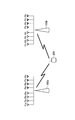
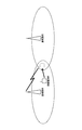
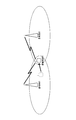
- the mobile terminal M1 is located in the cell center region of the base station B1, is communicating with the base station B1, and is moving toward the cell edge region between the base station B1 and the base station B2.
- the mobile terminal M1 is located in the cell edge region between the base station B1 and the base station B2, and performs cooperative communication between the base station B1 and the base station B2.
- FIG. 21 and FIG. 22 it is understood that the mobile terminal performs communication with a single base station or cooperative communication with a plurality of base stations depending on the position of the mobile terminal with respect to the base station.
- the modulation scheme and coding rate MCS (Modulation and Coding Scheme)
- spatial multiplexing number layer, rank
- precoding weight precoding weight
- a base station B transmitted from the base station B as shown in FIG.
- the mobile terminal M estimates the downlink transmission path condition and performs uplink data transmission from the mobile terminal to the base station ( It is necessary to feed back feedback information FI such as CSI to the base station through the uplink).
- a multicarrier transmission method such as an OFDM (Orthogonal Frequency Division Multiplexing) method or an OFDMA (Orthogonal Frequency Division Multiple Access) method is used as a transmission method
- a reference signal specific to the base station As shown in FIG.
- a reference signal scattered (scattered) by resource elements in the frequency direction and the time direction can be used.
- the channel condition such as frequency response, received signal power to interference plus noise power ratio (SINR) is shown.
- SINR received signal power to interference plus noise power ratio
- Information CSI (Channel State Information)
- CQI Channel Quality Indicator
- RI Rank Indicator
- PMI Precoding Matrix Index
- Precoding matrix index Precoding matrix index
- the transmission path condition is calculated based on the reference signal from each base station apparatus, and, for example, the modulation scheme and coding rate corresponding to the transmission path condition are specified by feedback information.
- the modulation scheme and coding rate corresponding to the transmission path condition are specified by feedback information.
- the transmission path status regarding the cooperatively transmitted signals is calculated based on the reference signal from each base station apparatus.
- the transmission line situation is different from the transmission line situation. For this reason, the conventional feedback information has a problem that it does not have appropriate contents when cooperative communication is performed.
- the present invention has been made in view of the above problems, and an object of the present invention is to generate appropriate feedback information in a wireless communication system capable of performing cooperative communication, whether or not the cooperative communication is performed.
- An object is to provide a wireless communication system, a wireless communication apparatus, and a wireless communication method.
- a wireless communication system of the present invention is a wireless communication system having at least two first communication devices and at least one second communication device communicating with the first communication device,
- the first communication device includes a reference signal generation unit that generates a reference signal, and a wireless transmission unit that transmits the reference signal and transmits transmission data to the second communication device.
- the communication device uses a reference signal from at least one of the first communication devices to measure a transmission path condition with the one first communication device, from other first communication devices. Transmission with the first first communication apparatus using a first transmission path condition measurement unit for measuring a transmission path condition including interference due to a signal and a reference signal from at least one first communication apparatus.
- the other said A second transmission path condition measurement unit that measures to suppress interference due to signals from the first communication device comprises a.
- wireless communications system of this invention is the above-mentioned radio
- wireless communications system of this invention is the above-mentioned radio
- generation part is a predetermined series, Comprising: Based on a series different between said 1st communication apparatuses.
- the second transmission path condition measurement unit performs the despreading process using the sequence on the reference signal from the first communication device, thereby obtaining the other first signal. Interference caused by signals from other communication devices is suppressed.
- wireless communications system of this invention is the above-mentioned radio
- the second communication apparatus further includes a communication method selection unit that selects one of the first transmission path condition measurement unit and the first communication channel based on the communication method selected by the communication method selection unit.
- a communication system switching unit that switches between two transmission path status measurement units.
- the wireless communication system of the present invention is the above-described wireless communication system, wherein the communication method switching unit communicates between the first communication device and at least one second communication device.
- the communication mode is switched to the first transmission path state measurement unit, and a plurality of the first communication devices cooperate with each other to communicate with at least one mobile terminal device 200. Switch to the second transmission path condition measurement unit.
- wireless communications system of this invention is the above-mentioned radio
- wireless communications system of this invention is the above-mentioned radio
- wireless communications system of this invention is the above-mentioned radio
- the said 2nd communication apparatus is further equipped with the propagation path estimation part which estimates a propagation path fluctuation value based on the said reference signal.
- the second transmission path condition measurement unit determines a combination of the reference signals to be despread based on the propagation path fluctuation value.
- the wireless communication system of the present invention is the above-described wireless communication system, wherein the second transmission path condition measurement unit is reversely operated based on interference power from the surrounding first communication device. A combination of the reference signals to be spread is determined.
- wireless communications system of this invention is the above-mentioned radio
- the said 2nd transmission-line condition measurement part combines the said reference signal distributed in the frequency direction, and carries out a de-spreading process. .
- the wireless communication system of the present invention is the above-described wireless communication system, wherein the second transmission path condition measurement unit performs despreading processing by combining the reference signals distributed in the time direction. .
- a wireless communication device of the present invention is a wireless communication device in a wireless communication system including at least two other wireless communication devices and at least one wireless communication device that communicates with the other wireless communication devices. Then, when measuring a transmission path condition with the one other wireless communication device using a reference signal from the at least one other wireless communication device, interference due to a signal from the other wireless communication device is detected. Using a first transmission path condition measurement unit that measures the included transmission path condition and a reference signal from at least one other wireless communication apparatus, measure the transmission path condition with the one other wireless communication apparatus A second transmission path condition measurement unit that performs measurement while suppressing interference caused by signals from other wireless communication devices.
- the wireless communication method of the present invention is a wireless communication in a wireless communication system having at least two first communication devices and at least one second communication device communicating with the first communication device.
- a first method in which the first communication device generates a reference signal and a method in which the first communication device transmits transmission data to the second communication device together with the reference signal. 2 and when the second communication device measures a transmission path condition with the first communication device using at least one reference signal from the first communication device.
- the one first communication device When measuring feed path condition has a fourth step of measuring by suppressing the interference due to signals from other of said first communication device.
- FIG. 1 is a schematic diagram showing the configuration of a wireless communication system according to a first embodiment of the present invention. It is a schematic block diagram which shows the structure of the base station apparatus 100a in the same embodiment. It is a figure which shows the mapping of a reference signal when the number of antenna ports in the embodiment is 4. It is a schematic block diagram which shows the structure of the mobile terminal device 200 in the embodiment. It is a schematic block diagram which shows the structure of the feedback information generation part 212 in the embodiment. It is a figure which shows an example of the reference signal and its mapping in the embodiment. It is a figure which shows an example of the reference signal and its mapping in the embodiment. It is a figure which shows another example of the reference signal in the same embodiment, and its mapping.
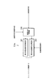
- FIG. 1 is a schematic diagram illustrating a configuration of a wireless communication system according to the present embodiment.
- the mobile communication system which is a wireless communication system in the present embodiment, includes base station apparatuses 100a and 100b (also referred to as a first communication apparatus, a cell, a transmission point, and a transmission antenna group) and a plurality of base station apparatuses 100a and 100b.
- Mobile terminal apparatus 200 also referred to as a second communication apparatus or a receiving terminal
- base station apparatuses 100a and 100b In the example illustrated in FIG.
- the mobile terminal device 200 is located in a region where a cell C1 that is a communication range of the base station device 100a and a cell C2 that is a communication range of the base station device 100b overlap. Since the base station apparatus 100a and the base station apparatus 100b have the same configuration, the configuration of the base station apparatus 100a will be described below, and the description of the configuration of the base station apparatus 100b will be omitted. In the present embodiment, the mobile communication system has been described as having a plurality of mobile terminal devices 200, but there may be one.
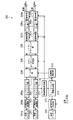
- FIG. 2 is a schematic block diagram showing the configuration of the base station apparatus 100a in the present embodiment.
- base station apparatus 100a includes coding sections 101a to 101n, scrambling sections 102a to 102n, modulation sections 103a to 103n, layer mapping section 104, precoding section 105, resource element mapping sections 106a to 106m, and OFDM signals.
- Generation units 107a to 107m, transmission antennas 108a to 108m, reference signal generation unit 114, reception antenna 110, reception signal processing unit 111, feedback information processing unit 112, control information generation unit 113, control unit 115, and communication unit 116 are provided.
- the encoding units 101a to 101n, the scramble units 102a to 102n, and the modulation units 103a to 103n indicate that each component has the maximum number of codewords to be transmitted in parallel, and the resource element mapping units 106a to 106m, It shows that the OFDM signal generation units 107a to 107m and the transmission antennas 108a to 108m have the same number of transmission antennas.
- the receiving antenna 110 receives a data signal including feedback information transmitted from the mobile terminal apparatus 200 through an uplink.
- the reception signal processing unit 111 performs reception processing for transmission processing performed by the mobile terminal apparatus 100 for transmission, such as OFDM demodulation processing, demodulation processing, and decoding processing, on the data signal received by the reception antenna 110, and receives the received data signal.
- Data RD1 and control data are obtained.
- Reception signal processing section 111 outputs control data to feedback information processing section 112 and control section 115.
- the reception data RD1 is data obtained by performing demodulation processing, decoding processing, and the like on the transmission data signal transmitted by the mobile terminal device 200
- the control data is the base station devices 100a and 100b, Data for controlling communication with the mobile terminal device 200.
- SC-FDMA Single carrier-frequency division multiple access
- uplink that is, signal transmission from the mobile terminal to the base station.
- User multiplexing may be performed using any one of multiple access schemes such as OFDMA, time division multiple access, and code division multiple access.
- various methods can be used as a method of identifying the transmission source mobile terminal apparatus 200 for control data such as feedback information.
- the base station apparatus 100a designates resources (elements for signal transmission divided by time, frequency, code, space domain, etc.) used for transmission of feedback information to each mobile terminal apparatus 200, and the mobile terminal Device 200 transmits feedback information on the specified resource.
- the base station apparatus 100a can identify the mobile terminal apparatus 100a that is the transmission source of the feedback information, based on the resource in which the feedback information is arranged. Further, a unique identification number or the like is added to each feedback information for each mobile terminal apparatus 200, and the base station apparatus 100a moves the source of the feedback information based on the identification information when receiving the feedback information.
- the terminal device 100a can be identified.
- the feedback information processing unit 112 extracts feedback information such as CSI, CQI, PMI, and RI from the input control data, and performs various adaptations to the data signal to be transmitted to the mobile terminal device 200 based on the feedback information.
- Control signals for performing control are output to encoding sections 101a to 101n, modulation sections 103a to 103n, layer mapping section 104, precoding section 105, and resource element mapping sections 106a to 106m.
- the base station apparatus 100a performs adaptive control according to the transmission format. Specifically, since the CQI is information indicating a coding rate and a modulation scheme, the feedback information processing unit 112 performs coding units 101a to 101n (coding rate) and modulation units 103a to 103n (modulation scheme) according to the CQI, respectively. To control.
- the feedback information processing unit 112 controls the precoding unit 104 according to the PMI. Since RI is information indicating the number of layers (ranks), the feedback information processing unit 112 controls the layer mapping unit 104 and an upper layer processing unit (not shown) that generates a codeword according to the RI. Further, when feedback information related to mapping to resources is also included, the resource element mapping units 106a to 106m can be controlled.
- the feedback information processing unit 112 can determine the transmission format (communication parameter) based on the information indicating the transmission path status and perform optimal control. For example, the mobile terminal apparatus 200 maximizes the power when receiving a signal from the base station apparatus 100a based on the information indicating the fed back transmission path condition, or the base station apparatus 100a and the base station apparatus.
- the precoding matrix (communication parameters) is determined so that the power when receiving a signal from 100b is maximized, and the optimum coding rate, modulation scheme, and number of layers at that time can be determined. Can be used.
- the information indicating the transmission path status includes the frequency response indicating the amplitude and phase shift of each subcarrier by the transmission path, the time response indicating the complex amplitude for each delay time with respect to the preceding wave, and signal-to-interference / noise.
- a power ratio (SINR) or the like can be used.
- the control unit 115 determines whether or not the mobile terminal device 200 generates feedback information for performing cooperative communication with the adjacent cell based on the input control data (or simply performs cooperative communication). Whether or not).
- cooperative communication is also referred to as a first communication method
- communication that does not use cooperative communication is also referred to as a second communication method.
- the control information generation unit 113 generates a communication method control signal for notifying the content determined by the control unit 115 described above, and further multiplexes the generated communication method control signal as a control data signal to a transmission data signal described later, In order to transmit to the mobile terminal device 200, it is output to the resource element mapping units 106a to 106m.
- the control unit 115 determines whether or not the mobile terminal device 200 generates feedback information for performing cooperative communication with an adjacent cell
- the mobile terminal device 200 includes feedback in the control data.
- the control data As a result of comparing the received power ratio or the path loss difference between neighboring cells with a preset threshold value, it can be determined based on a method of determining that it is generated when it is smaller than the threshold value or a method of performing handover control .
- the contents of the decision not only determine whether or not to perform cooperative communication, but also determine what communication method of cooperative communication is to be performed (for example, Joint Processing, Joint Transmission, etc.), and a signal indicating the determined communication method
- the communication method control signal may be included, or a signal specifying the feedback information of the item corresponding to the determined communication method may be included in the communication method control signal.
- the communication system control signal is multiplexed with other control data signals and transmitted. Further, the communication method control signal may be transmitted after performing an encoding process, a scramble process, a modulation process, a precoding process, and the like, similarly to a transmission data signal described later. Further, the communication system control signal may be transmitted by transmission from one transmission antenna, transmission by transmission diversity using a plurality of transmission antennas, transmission by spatial multiplexing transmission using a plurality of transmission antennas, or the like. .
- control unit 115 is connected to the network 300 via the communication unit 116, and can communicate with other base station devices (for example, the base station device 100b) via the network 300.
- the control unit 115 of the base station device 100a communicates with the base station device 100b, performs frame synchronization and symbol synchronization between the base station devices, and controls the signal output timing of the OFDM signal generation unit 107. Further, for example, when performing Joint ⁇ Processing and Joint Transmission, the control unit 115 of the base station device 100a communicates with the base station device 100b and passes transmission data transmitted from the base station device 100a to the base station device 100b.
- the transmission data is also transmitted from the base station apparatus 100b, or the transmission data transmitted from the base station apparatus 100b is received from the base station apparatus 100b, and the transmission data is input to the encoding units 101a to 101n for transmission. Thereby, the transmission data transmitted from the base station apparatus 100a and the base station apparatus 100b are matched.
- Each of the code units 101a to 101n receives one codeword (transmission data TD1a to TD1n, information data signal) to be transmitted, which is input from a higher-level processing device of the base station apparatus 100a (not shown).
- the code word is input to the number of code units for transmitting the code word in parallel, and nothing is input to the other code units.
- Each of the encoding units 101a to 101n encodes an input code word with an error correction code such as a turbo code, a convolutional code, or an LDPC (Low Density Parity Check) code, and corresponds to one of the scramble units 102a to 102n. Output to the scramble unit.
- an error correction code such as a turbo code, a convolutional code, or an LDPC (Low Density Parity Check) code
- the coding rate in this coding follows the instruction of the feedback information processing unit 112.
- the codeword is a block of transmission data, and may be a processing unit for performing retransmission control such as HARQ (Hybrid Automatic Repeat reQuest), or a process for performing error correction coding. It may be a unit or a processing unit for performing error detection coding.
- HARQ Hybrid Automatic Repeat reQuest
- Each of the scramblers 102a to 102n generates a different scramble code for each base station apparatus based on the cell ID, etc., and is a signal encoded by the code part corresponding to the scramble part among the code parts 101a to 101n.
- a scramble process is performed using the generated scramble code.
- the same scramble code is generated between base station apparatuses and scramble processing is performed.
- Each of the modulation units 103a to 103n includes modulation such as BPSK (Binary Phase Shift Keying), QPSK (Quadrature Phase Shift Keying), and QAM (Quadrature Amplitude Modulation).
- modulation such as BPSK (Binary Phase Shift Keying), QPSK (Quadrature Phase Shift Keying), and QAM (Quadrature Amplitude Modulation).
- the scramble unit corresponding to the modulation unit among the scramble units 102a to 102n performs modulation processing on the signal subjected to scramble processing.
- the modulation method in this modulation process follows the instruction of the feedback information processing unit 112.
- the layer mapping unit 104 maps the signal output from each of the modulation units 103a to 103n to a layer (rank) that performs spatial multiplexing such as MIMO (Multi-Input Multi-Output). For example, if the number of codewords is 2 and the number of layers is 4, it is possible to change the number of layers to 4 by converting each codeword into two parallel signals. Absent. Note that the number of layers follows the instruction of the feedback information processing unit 112.
- the precoding unit 105 performs precoding processing on the signal output from the layer mapping unit 104 and converts the signal into parallel signals of the number of antenna ports (transmission antennas).
- the precoding process is a process of multiplying a precoding matrix instructed from the feedback information processing unit 112 by a signal sequence, a process using a precoding matrix determined in advance, CDD (Cyclic Delay Diversity), SFBC. (Spatial Frequency Block Code), STBC (Spatial Time Block Code), TSTD (Time Switched Transmission Diversity), FSTD (Frequency Switched Transmission Diversity)
- CDD Cyclic Delay Diversity
- SFBC Spatial Frequency Block Code
- STBC Sesian Time Block Code
- TSTD Time Switched Transmission Diversity
- FSTD Frequency Switched Transmission Diversity
- the reference signal generation unit 114 generates reference signals known to each other in the base station device 100a and the mobile terminal device 200, and outputs them to the resource element mapping units 106a to 106m.
- any signal can be used as long as the signal is known to the base station device 100a and the mobile terminal device 200.
- a method of generating from a random number based on a cell ID or the like and a method of generating a signal based on a pseudo noise sequence (pseudo random sequence, spreading code, PN (Pseudo Noise) sequence) Details will be described later.
- an M (Maximum-length) sequence Gold code, orthogonal Gold code, Barker code, orthogonal code sequence (for example, Walsh code, OVSF (Orthogonal Variable Spreading Factor) code, Hadamard code) or the like is used. Furthermore, a sequence obtained by cyclically shifting these sequences or a sequence expanded cyclically may be used. Moreover, what searched for the series excellent in the autocorrelation characteristic and the cross correlation characteristic using the computer etc. may be used, It is not restricted to these.
- the resource element mapping units 106a to 106m receive the transmission data signal output from the precoding unit 105, the reference signal output from the reference signal generation unit 114, and the control data signal output from the control information generation unit 113, respectively. To the resource element.
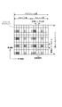
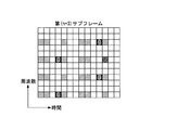
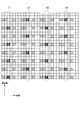
- FIG. 3 shows mapping of reference signals when the number of antenna ports is four.
- FIG. 3 is a diagram for explaining the arrangement of reference signals in resource blocks.
- FIG. 3 shows a case where two resource blocks composed of 12 subcarriers in the frequency direction and 7 OFDM symbols in the time direction are arranged in the time direction. Each subcarrier in one OFDM symbol is also called a resource element.
- the length of the resource block in the time direction is called a slot length, and the length in the time direction of two resource blocks continuous in the time direction is called a subframe length.
- the numbers attached to the hatched resource elements indicate that the reference signals of the antenna ports 1 to 4 are arranged.
- the reference signal of antenna port 1 in the first OFDM symbol in the time direction, is arranged in the resource element of the first subcarrier from the lowest frequency, and antenna port 2 is assigned to the resource element of the fourth subcarrier.
- the reference signal of antenna port 1 is arranged in the resource element of the seventh subcarrier, and the reference signal of antenna port 2 is arranged in the resource element of the tenth subcarrier.
- the reference signal of antenna port 3 is arranged in the resource element of the first subcarrier from the lowest frequency, and the reference of antenna port 4 is assigned to the resource element of the fourth subcarrier.
- the signal is arranged, the reference signal of the antenna port 3 is arranged in the resource element of the seventh subcarrier, and the reference signal of the antenna port 4 is arranged in the resource element of the tenth subcarrier.
- the reference signal of antenna port 1 is arranged in the resource element of the first subcarrier, and the reference signal of antenna port 2 is arranged in the resource element of the fourth subcarrier.
- the antenna port 1 reference signal is arranged in the seventh subcarrier resource element, and the antenna port 2 reference signal is arranged in the tenth subcarrier resource element.
- the 8th OFDM symbol from the beginning refers to the same as the 1st OFDM symbol, the 9th OFDM symbol the same as the 2nd OFDM symbol, and the 12th OFDM symbol the same as the 5th OFDM symbol.
- the signal is arranged.
- No resource is assigned to resource elements in other antenna ports that have the same time and frequency as the resource elements of the reference signal mapped to each antenna port.
- the reference signals are orthogonalized. Note that the number of OFDM symbols in the resource block can be changed. For example, when a long guard interval length is added, the number of OFDM symbols in one slot can be six. Note that a transmission data signal or a control data signal is mapped to resource elements other than the resource element to which the reference signal in the figure is mapped.
- the number of resource blocks varies depending on the frequency bandwidth (system bandwidth) used by the communication system. For example, depending on the frequency bandwidth, 6 to 110 resource blocks may be used in the frequency direction, and the total system bandwidth may be increased to 110 or more by frequency aggregation.
- each component carrier that divides the entire system band is composed of 100 physical resource blocks, and the total system bandwidth is 500 physical resource blocks with 5 component carriers with a guard band between the component carriers. Also good.
- the component carrier is composed of 20 MHz, and the total system bandwidth can be set to 100 MHz with five component carriers with the guard band between the component carriers.
- a signal based on a pseudo-noise sequence is assigned to a reference signal in at least one antenna port, and a signal generated from a random number based on a cell ID is assigned to a reference signal in the remaining antenna ports. Details will be described later.
- a transmission data signal or a control data signal is mapped to resource elements other than the reference signal.
- each of the OFDM signal generators 107a to 107m converts the frequency domain signal output by the corresponding resource element mapping unit out of the resource element mapping units 106a to 106m into an inverse fast Fourier transform (IFFT (Inverse)).
- IFFT inverse fast Fourier transform
- IFFT Fast Fourier Transform
- a guard interval cyclic prefix
- each of the OFDM signal generators 107a to 107m converts the signal with the guard interval added from a digital signal to an analog signal, performs a conversion process from a baseband to a radio frequency, and the like, and then transmits the signals from the transmission antennas 108a to 108m. Of these, transmission is performed from the corresponding transmission antenna.
- FIG. 4 is a schematic block diagram showing the configuration of the mobile terminal device 200 in the present embodiment.
- mobile terminal apparatus 200 includes receiving antennas (receiving antenna ports) 201a to 201l, OFDM signal demodulation sections 202a to 202l, resource element demapping sections 203a to 203l, filter section 204, deprecoding section 205, layer demapping.
- Unit 206 demodulation units 207a to 207n, descrambling units 208a to 208n, decoding units 209a to 209n, propagation path estimation unit 210, control information reception unit 211, feedback information generation unit 212, transmission signal generation unit 213, and transmission antenna 214 Prepare.
- Receiving antennas 201a to 201l, OFDM signal demodulating sections 202a to 202l, and resource element demapping sections 203a to 203l indicate that each component has the same number of receiving antennas, demodulating sections 207a to 207n, descrambling sections 208a to 208n and decoding units 209a to 209n indicate that base station apparatus 100a or base station apparatus 100b has the maximum number of codewords to be transmitted in parallel.
- the transmission antennas 108a to 108m function as a wireless transmission unit.
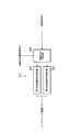
- FIG. 5 is a schematic block diagram showing the configuration of the feedback information generation unit 212 in the present embodiment.
- the feedback information generation unit 212 includes a communication method switching unit 220, a first transmission path state measurement unit 221, and a second transmission path state measurement unit 222.
- the mobile terminal device 200 includes at least one receiving antenna 201a, and each of the receiving antennas 201a to 201l receives a signal transmitted by the base station devices 100a and 100b and passing through a transmission path (propagation path or channel). .
- Each of the OFDM signal demodulation units 202a to 202l performs a conversion process from a radio frequency to a baseband signal and a conversion process from an analog signal to a digital signal for a signal received by the corresponding reception antenna among the reception antennas 201a to 201l. Do.
- the OFDM signal demodulation sections 202a to 202l further remove the guard interval added by the base station apparatus 100a or the base station apparatus 100b from the digital signal obtained by this conversion processing, and then perform fast Fourier transform (FFT (Fast Fourier Transform)). Transform)), etc. to perform a time-frequency conversion process to convert the signal into a frequency domain signal.
- FFT Fast Fourier transform
- Transform Transform
- k is a subcarrier number
- NT is the number of transmission antennas
- NR is the number of reception antennas
- R (k) is a reception signal corresponding to each reception antenna
- S (k) is a transmission signal corresponding to each transmission antenna
- N ( k) represents noise corresponding to each receiving antenna
- H (k) represents frequency response corresponding to each receiving antenna and each transmitting antenna
- T represents a transposed matrix.
- the element of H (k) is, for example, the transmission of the base station apparatus 100a.
- the frequency response of the transmission path of the reception antenna 201a of the mobile terminal apparatus 200 from the antenna 108a and the frequency response of the transmission path of the reception antenna 201a of the mobile terminal apparatus 200 to the transmission antenna 108a of the base station apparatus 100b are combined. ing.
- the element of H (k) is further added to these.
- Resource element demapping sections 203a to 203l demap (separate) the transmission data signal, control data signal, and reference signal mapped by base station apparatuses 100a and 100b, and transmit the transmission data signal to filter section 204 and the reference signal.
- the control data signal is output to feedback information generating section 212 and propagation path estimating section 210, and to control information receiving section 211.
- the propagation path estimation unit 210 estimates the amplitude and phase fluctuations (frequency response, transfer function) in each resource element based on the comparison between the input reference signal and the known reference signal, so that the propagation path Make an estimate.
- the resource element to which the reference signal is not mapped performs channel estimation by interpolating the channel estimation result of the resource element to which the reference signal is mapped in the frequency direction and the time direction.
- various methods such as linear interpolation, parabolic interpolation, polynomial interpolation, Lagrange interpolation, spline interpolation, FFT interpolation, and minimum mean square error (MMSE (Minimum Mean Square Estimation)) interpolation can be used.
- MMSE Minimum Mean Square Estimation
- the filter unit 204 performs channel compensation on the data signals for the receiving antennas 201a to 201l output from the resource element demapping units 203a to 203l using the channel estimation values output from the channel estimation unit 210, A transmission signal S (k) is detected.
- a ZF (Zero Forcing) standard, an MMSE standard method, or the like can be used as the detection method.
- the weighting factors used for detection of the ZF criterion or the MMSE criterion are MZF and MMMSE, respectively, they are expressed by the following equations (2) and (3).
- H ⁇ (k) is the estimated frequency response
- H ⁇ H (k) is the complex conjugate transpose of H ⁇ (k)
- -1 is the inverse matrix
- ⁇ ⁇ 2 is the noise power
- INR is NR ⁇ NR. Represents the identity matrix.
- a transmission data signal for each of the transmission antennas 108a to 108m is estimated using one of these weighting factors M (k). If the estimated transmission data signal is S ⁇ (k), it can be detected using the following equation (4).
- the deprecoding unit 205 performs processing for returning the precoding processing performed in the base station apparatuses 100a and 100b to the transmission data signal detected by the filter unit 204. In addition, when the base station apparatuses 100a and 100b perform precoding processing using CDD, the deprecoding unit 205 may not perform processing for CDD.
- the layer demapping unit 206 performs demapping processing on the signal for each layer into each codeword.
- Each of the demodulation units 207a to 207n is associated with one of the code words, and a signal of the code word is input.
- Each of the demodulation units 207a to 207n performs demodulation corresponding to the modulation method used in the transmission source base station apparatus of the base station apparatuses 100a and 100b with respect to the input signal.
- Each of the descrambling units 208a to 208n performs descrambling processing corresponding to the scramble code used in the base station apparatuses 100a and 100b on the demodulation result by the corresponding demodulating unit among the demodulating units 207a to 207n.
- Decoding sections 209a to 209n perform error correction decoding processing corresponding to the encoding method used in base station apparatuses 100a and 100b, detect received data RD2a to RD2n, and process apparatuses in higher layers of mobile terminal apparatus 200 (not shown) Output to.
- control information receiving unit 211 receives a control data signal output from at least one of the resource element demapping units 203a to 203l and extracts a communication method control signal from the received control data signal.
- the control information receiving unit 211 sends a signal indicating whether or not the mobile terminal device 200 generates feedback information for performing cooperative communication with the adjacent cell to the feedback information generating unit 212 according to the extracted communication method control signal. Output.
- the control information receiving unit 211 is a communication parameter specified by the control data signal, and the coding rate, modulation scheme, and precoding matrix used when the base station apparatuses 100a and 100b transmit the transmission data signal. In accordance with communication parameters such as the number of ranks, the decoding units 209a to 209n, the demodulation units 207a to 207n, the deprecoding unit 205, and the filter unit 204 are controlled.
- the feedback information generation unit 212 (communication parameter determination unit) generates feedback information based on the reference signals output from the resource element demapping units 203a to 203l.
- the received signal power to interference / noise power ratio SINR (Signal to Interference plus Noise power Ratio)
- received signal power A method of measuring an interference power ratio (SIR (Signal-to-Interference-power Ratio)), a received signal power-to-noise power ratio (SNR (Signal-to-Noise power ratio)), a path loss, or the like can be used.
- the frequency direction for example, for each subcarrier, for each resource element, for each resource block, for each subband composed of a plurality of resource blocks
- the time direction for example, for each OFDM symbol, It can be divided into subframes, slots, radio frames, etc.
- spatial directions for example, antenna ports, transmission antennas, reception antennas, etc.
- information specifying a recommended transmission format may be used as feedback information, or information indicating a transmission path condition is used. May be.
- precoding matrix information for example, PMI
- MCS information for example, CQI specifying a coding rate and a modulation scheme
- layers of the base station devices 100a and 100b Layer number information (for example, RI) mapped by the mapping unit 104 can be used.
- information indicating a transmission path condition when information indicating a transmission path condition is used, information indicating a transmission path quality such as SINR among the transmission path conditions measured by the mobile terminal apparatus 200 can be used as feedback information.
- the feedback information generation unit 212 generates feedback information FI according to the communication method control signal CC extracted by the control information reception unit 211.
- the communication method control signal CC output from the control information receiving unit 211 is input to the communication method switching unit 220 in FIG.
- the communication system switching unit 220 selects either the first transmission path state measurement unit 221 or the second transmission path state measurement unit 222 based on the communication system control signal CC, and the resource element The reference signal RS input from the demapping units 203a to 203l is output.
- the communication system switching unit 220 selects the first transmission path condition measurement unit 221 when the communication system control signal CC indicates that feedback information for performing cooperative communication with the neighboring cell is not generated. To do.
- the communication system switching unit 220 selects the second transmission path condition measuring unit 222 when the communication system control signal CC indicates that feedback information for performing cooperative communication with an adjacent cell is generated. .
- the reference signal RS is input to the first transmission path condition measurement unit 221, and 1 transmission path condition measurement unit 221 measures the transmission path condition using each reference signal RS as an independent signal, and generates feedback information FI. That is, the first transmission path condition measurement unit 221 measures the transmission path condition including interference due to signals from other base station apparatuses.
- the transmission path condition refers to a propagation path response such as a frequency response representing fluctuations in amplitude and phase, and a propagation path quality such as a signal-to-noise ratio (SN ratio) and a signal-to-interference noise power ratio (SINR). It is information such as.
- the reference signal RS is input to the second transmission path condition measurement unit 222.
- the second transmission path condition measuring unit 222 performs despreading processing on the reference signal RS, and then measures the transmission path condition to generate feedback information. That is, the second transmission path condition measurement unit 222 performs measurement while suppressing interference caused by signals from other base station apparatuses. Details of generation of the feedback information FI by the second transmission path condition measurement unit 222 will be described later.
- the first transmission path condition measurement unit 221 uses the reference signal RS to calculate a signal-to-noise ratio (SN ratio) that represents transmission path quality, and uses this as feedback information FI.
- SN ratio signal-to-noise ratio
- the despreading process is an autocorrelation of arbitrary signals known to each other, that is, reference signals, for example, in units of generating feedback information, in the base station apparatuses 100a and 100b and the mobile station apparatus 200.
- an autocorrelation value can be obtained for an arbitrary signal (for example, a signal generated by a random number or the like).
- the reference signal is preferably generated based on a pseudo noise sequence. This is because the autocorrelation value is further improved.
- the unit for generating feedback information and the unit for performing despreading processing may be different.
- the transmission signal generation unit 213 encodes, modulates, and modulates the feedback information FI together with the transmission data TD2, in order to transmit (feedback) the feedback information FI output from the feedback information generation unit 212 to the base station apparatuses 100a and 100b.
- An OFDM signal generation process or the like is performed to generate a transmission signal.
- Transmitting antenna 214 transmits a transmission signal including feedback information generated by transmission signal generating section 213 to base station apparatuses 100a and 100b through an uplink. Note that the feedback information may be transmitted to either one of the base station devices 100a and 100b or may be transmitted to both, depending on the location status of the mobile terminal device 200.
- reference signal generation and mapping reference signal generation based on a pseudo noise sequence by the reference signal generation unit 114 in the base station apparatuses 100a and 100b, and time directions by the resource element mapping units 106a to 106m
- the mapping of the reference signal generated for every two consecutive resource blocks will be described.
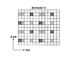
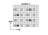
- 6A and 6B are diagrams illustrating an example of reference signals and mapping thereof in the present embodiment. This figure shows a case where a reference signal (8 chips (bits)) to be assigned to the antenna port 1 among the four antenna ports shown in FIG. 3 is generated based on a pseudo noise sequence.
- a sequence having excellent autocorrelation characteristics such as an M sequence (that is, a sharp (high) correlation value (peak value) is obtained when the sequence is synchronized when despreading is performed).
- a sequence in which a very low correlation value is obtained when the sequence is out of synchronization is used.
- a sharp correlation value is obtained at the position a for the 8-chip series a to h. That is, the correlation value between the series “a, b, c, d, e, f, g, h” and the series “a, b, c, d, e, f, g, h” becomes a maximum value.
- the correlation value between the series “a, b, c, d, e, f, g, h” and the series “h, a, b, c, d, e, f, g” is equal to the previous maximum value. A sufficiently small value.
- a reference signal is obtained by cyclically shifting these 8-chip sequences a to h.
- the position where a sharp correlation value is obtained can be made different for each cell.
- the resource elements to which the resource element mapping unit 106a of the base station apparatus 100a and the base station apparatus 100b in the present embodiment maps the reference signal are the same.
- the reference signal generation unit 114 of the base station apparatus 100a uses, as a reference signal for the antenna port 1, a signal “a” obtained by shifting a signal based on a pseudo noise sequence, that is, a sequence a to h, which is a pseudo noise sequence, by 0 chip. , B, c, d, e, f, g, h ”.
- the resource element mapping unit 106a of the base station apparatus 100a maps the generated reference signal in order from the chip a as shown in FIG. 6A.
- the reference signal generation unit 114 of the base station apparatus 100b uses a signal based on a pseudo noise sequence, that is, a signal obtained by shifting the sequences a to h, which are pseudo noise sequences, by one chip as a reference signal for the antenna port 1. “H, a, b, c, d, e, f, g” are generated.
- the resource element mapping unit 106a of the base station apparatus 100b maps the generated reference signal in order from the chip h as shown in FIG. 6B.
- the mobile terminal apparatus 200 that performs cooperative communication with the base station apparatus 100a and the base station apparatus 100b uses feedback information for each of the base station apparatuses 100a and 100b independently using reference signals. Let us consider the case of generating based on the estimated transmission path condition. As a reference signal to be used, based on a random number generated from a unique ID number or the like that each base station device (cell) recognizes the base station device (cell), when performing estimation using each reference signal independently, Adjacent cells interfere with each other. In particular, the mobile terminal apparatus 200 in the cell edge region generates feedback information based on the transmission path condition estimated in a situation where the inter-cell interference is large.
- the mobile terminal apparatus 200 in the cell edge region tries to perform cooperative communication, it is necessary to generate feedback information for each of the base station apparatuses 100a and 100b that are going to perform cooperative communication depending on the method of cooperative communication.
- the inter-cell interference is suppressed or reduced.
- the channel condition estimated for feedback information is a situation in which inter-cell interference is large, but is significantly different from the situation in which inter-cell interference in which cooperative communication is actually performed is suppressed or reduced. Become.
- optimum feedback information for performing cooperative communication cannot be obtained.
- dedicated reference signals for cooperative communication are installed so that they do not collide with each other between neighboring cells (so that they do not coincide with each other in frequency and time), and they are referred to each other. It is conceivable to make the resource element located in the signal zero (null). In this way, since the reference signals are orthogonal to each other between adjacent cells, when the mobile terminal device 200 performs cooperative communication, the transmission path condition is estimated with inter-cell interference eliminated. Optimal feedback information for performing cooperative communication can be generated.
- such a method has a problem that transmission efficiency is lowered because the number of resource elements in which reference signals are arranged increases and the number of resource elements in which transmission data signals can be arranged decreases.
- the reference signals when the reference signals are mapped as shown in FIGS. 6A and 6B, the reference signals from the base station apparatus 100a and the base station apparatus 100b are received simultaneously, and the mobile terminal apparatus 200 performs cooperative communication. Since the position of the peak value obtained by the reference signal from each base station apparatus differs by performing despreading, the resource elements located in each reference signal are set to zero ( Null), that is, without reducing the transmission efficiency, it is possible to suppress interference from adjacent cells and generate optimal feedback information for cooperative communication.
- the reference signal based on the pseudo-noise sequence can be used independently of each other as in the past without increasing new processing and the like. Optimal feedback information can be generated when cooperative communication is not performed. Further, when the mobile terminal device 200 does not perform cooperative communication, it is not necessary to measure the reference signals of all the neighboring cells in order to measure the interference power from the neighboring cells, and the control data and the like are newly moved. This can be realized without notifying the terminal device 200. Further, it is realized without increasing the ratio (overhead) of the reference signal to the entire resource without changing the structure of the reference signal between the case where the mobile terminal device 200 performs cooperative communication and the case where the mobile terminal device 200 does not perform cooperative communication. it can.
- sequences having excellent autocorrelation characteristics such as M sequences are mutually shifted between adjacent cells.
- the present invention is not limited to this.
- a sequence having excellent cross-correlation characteristics such as Hadamard code can be used.
- the reference signals based on the pseudo noise sequence are orthogonalized between adjacent cells. This orthogonality can be realized using various methods. For example, a method in which a control station located above the base station devices 100a and 100b assigns, a method in which base stations cooperate with each other through a line or radio for communicating control signals such as an X2 interface, and parameters such as cell IDs in advance. The method etc.
- the X2 interface is a line (channel, transmission path) for connecting base stations located adjacent to or around each other via a wired line and communicating control signals and data signals with each other through the wired line. .
- the mobile terminal apparatus 200 may specify the pseudo noise sequence and the number of shifts using parameters such as cell IDs notified from the base station apparatuses 100a and 100b.
- the base station apparatus that transmits a control data signal to the mobile terminal apparatus 200 and the base station apparatus that the mobile terminal apparatus 200 transmits feedback information are: For example, any one of base station apparatuses 100a and 100b performing cooperative communication such as an anchor cell may be used. Further, even when the mobile terminal device 200 performs cooperative communication, the base station device that transmits a control data signal to the mobile terminal device 200 and the base station device that the mobile terminal device 200 transmits feedback information are: You may perform with respect to all the base station apparatuses 100a and 100b which are performing cooperative communication.
- FIG. 6A and FIG. 6B the case where the resource elements for mapping reference signals in the base station apparatus 100a and the base station apparatus 100b are the same has been described.
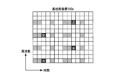
- FIG. 7A and FIG. 7B illustrate a case where the resource element that maps the reference signal in base station apparatus 100b is shifted by one subcarrier in the frequency direction as compared with base station apparatus 100a. Even in this case, mapping is performed in the same manner as described with reference to FIGS. 6A and 6B.
- the respective reference signals are not orthogonal to each other, but for example, a sequence having a sharp autocorrelation characteristic is used as a pseudo-noise sequence, and the mobile terminal device 200 performs despreading so that other cells Interference can be greatly reduced with each other, and optimal feedback information for cooperative communication can be generated.
- FIG. 8 is a flowchart for explaining feedback information generation processing of the mobile terminal device 200 according to the present invention.
- the mobile terminal apparatus 200 receives a communication scheme control signal as a part of the control data signal from the base station apparatus 100a or the base station apparatus 100b.
- the base station apparatus 100a or the base station apparatus 100b transmits the communication scheme control signal multiplexed with the transmission data signal as a part of the control data signal, but the upper layer signal (RRC signaling) (The wireless terminal control signal may be transmitted using the (radio resource control signal) or the system information notified by the broadcast channel).
- RRC signaling The wireless terminal control signal may be transmitted using the (radio resource control signal) or the system information notified by the broadcast channel.
- the mobile terminal device 200 receives the communication method control signal, the method specified by the communication method control signal is used. To start generating feedback information.
- step S1 the mobile terminal apparatus 200 receives a downlink signal transmitted by at least one base station apparatus.
- step S2 whether to generate feedback information for the mobile terminal device 200 to perform cooperative communication with a neighboring cell or to generate feedback information for communication with a serving cell based on the communication method control signal Determine.
- the mobile terminal apparatus 200 transitions to step S3, and the mobile terminal apparatus 200 despreads the received reference signal, Transition to S4.
- step S4 when it determines with producing
- step S4 when the mobile terminal device 200 generates feedback information for performing cooperative communication with an adjacent cell, that is, if the despreading process in step S3 is performed, the despreading reference signal is used. , Generate feedback information.
- the mobile terminal device 200 when the mobile terminal device 200 generates feedback information for performing communication with the serving cell (when generating feedback information other than performing cooperative communication with the neighboring cell), that is, the despreading process in step S3 is performed. If not, the reference signal is directly used as an independent signal to generate feedback information.
- step S5 an uplink signal for transmitting the generated feedback information to at least one base station apparatus is generated.
- the format of the uplink signal is set when setting feedback information.
- the format of the uplink signal defines the resource of the physical uplink control channel PUCCH or the physical uplink shared channel PUSCH that transmits feedback information, the feedback period, the RI, PMI, CQI bit string, and the like.
- step S6 the generated uplink signal is transmitted.
- the generation of feedback information is performed periodically or aperiodically according to the timing of feedback information transmission.
- the base station apparatus 100a notifies the mobile terminal apparatus 200 of a set of cells for which cooperative communication is to be performed, that is, a set of cells for which despreading processing is to be performed.
- the cell set information includes the number of cells, each cell ID, and the pseudo noise sequence of each cell. Note that a pseudo-noise sequence of a cell can be determined in advance by a cell ID or the like.
- the base station apparatus 100a uses a measurement report (Measurement Report) acquired from the mobile terminal apparatus 200 in order to determine a set of cells to perform this cooperative communication.
- feedback information generating section 212 of mobile terminal apparatus 200 performs despreading processing on the reference signals transmitted from the respective cells.
- CQI and PMI can be defined in advance as a plurality of types of patterns (indexing), and the one closest to the pattern can be selected.
- the CQI is determined as follows. In order to determine CQI, a lookup table of CQI (combination of coding rate and modulation scheme) satisfying required quality (bit error rate, etc.) with respect to SINR is defined in advance.
- the feedback information generation unit 212 obtains SINR when cooperative communication is performed from the result of the despreading process, and determines the CQI corresponding to the SINR from the lookup table.
- Ri is determined as follows. When determining the RI, it is determined based on the number of layers satisfying the required quality with respect to the SINR. Also, considering CQI and RI at the same time, for example, a lookup table of a combination of CQI and RI that satisfies the required quality (bit error rate, etc.) for SINR is defined in advance, and the lookup table is referred to , It may be determined to meet the required quality.
- the PMI is determined as follows. When determining the PMI, a precoding matrix that maximizes the received power is determined using the result of the despreading process. When determining CQI and RI, PMI may be determined first, and CQI and RI may be determined based on the transmission path considering the PMI. Note that the order of the feedback information generation is not limited to this.
- the transmission path condition (amplitude / phase fluctuation value, frequency response) at the receiving antenna port for each transmitting antenna port is obtained from the result of the despreading process.
- the difference between transmission path conditions that are continuous in the time direction or the frequency direction can be used as feedback information.
- the feedback information can be obtained for each subband of a predetermined bandwidth.
- the mobile terminal apparatus 200 combines the reference signals of the respective cells obtained by performing the despreading process. Then, the channel state is measured based on one combined reference signal, and feedback of CQI, PMI, and RI based on the combined channel state or the combined channel state is performed.
- the mobile terminal apparatus 200 uses the despreading process for each cell obtained.
- the channel state transmission path state
- the channel state for the necessary cells is fed back.
- the channel state can be expressed by a variation value of the phase and amplitude with respect to a signal for each resource (for example, resource element or resource block).
- the mobile terminal device 200 may be provided with either the first method or the second method by cooperative communication to be performed, or may be provided with both the first method and the second method. Feedback may be performed by the method specified by
- base station apparatuses 100a and 100b that perform cooperative communication share all or part of transmission data signals (codewords) transmitted to mobile terminal apparatus 200, and cooperate with mobile terminal apparatus 200.
- Transmission including simultaneous transmission from base stations in cooperative communication and transmission by dynamically switching between base stations in cooperative communication.
- transmission data signals (codewords) for the mobile terminal apparatus 200 are not shared between the base station apparatuses 100a and 100b that perform cooperative communication, and one base station apparatus (anchor base) is used for the mobile terminal apparatus 200. Station, serving base station), but information on interference and beams between the base station apparatuses 100a and 100b in cooperative communication is shared.
- the same precoding process such as transmitting the same transmission data signal (codeword) between base station apparatuses 100a and 100b in cooperative communication and performing spatial frequency block coding (SFBC), etc.
- feedback information is generated using the first method. That is, since base station apparatuses 100a and 100b transmit the same signal, feedback information generating section 212 of mobile terminal apparatus 200 combines the propagation path from base station apparatus 100a and the propagation path from base station apparatus 100b.
- Precoding such as a coding rate, an adaptive method, the number of ranks, and a block code that satisfies a desired quality (such as a bit error rate) is selected based on the SINR in the state.
- the base station apparatuses 100a and 100b are independent of each other such as transmitting the same transmission data signal (codeword) between the base station apparatuses 100a and 100b in cooperative communication and giving a phase difference between the base station apparatuses 100a and 100b.
- PMI is generated using the second method
- other feedback information is generated using the first method.
- feedback information is generated using the second method.
- the signal based on the pseudo noise sequence may be used for all the resource elements that map the reference signals of the respective antenna ports, only a part of them may be a signal based on the pseudo noise sequence.
- a signal based on a pseudo noise sequence may be assigned to a reference signal in at least one antenna port, and a signal generated from a random number based on a cell ID may be assigned to reference signals in the remaining antenna ports.
- the present invention can be applied if the number of antenna ports is one or more.
- the position of the resource element that maps the reference signal is shifted between adjacent cells based on the cell ID or the like has been described.
- the positions may be fixed among a plurality of cells that perform various cooperative communications.
- the reference signal is arranged in all the resource blocks has been shown, it may be arranged in only some of the resource blocks.
- a unit controlled by a base station such as an RRE (Remote Radio Equipment), an RRH (Remote Radio Head), or an independent antenna through a wire such as an optical fiber
- RRE Remote Radio Equipment
- RRH Remote Radio Head
- a unit that a base station such as a relay controls through radio a unit configured by a plurality of base stations that perform cooperative communication such as Active CoMP set, a unit of a resource element that maps a reference signal, and the like can be used.
- various identifications and various controls for communication can be performed using the type of pseudo-noise sequence and the position where the peak of the autocorrelation characteristic is obtained.
- the sequence length of the pseudo noise sequence used by base station apparatuses 100a and 100b may be different from the sequence length that mobile terminal apparatus 200 performs despreading processing on.
- the despreading process for the reference signal is performed to generate feedback information.
- the despreading process result may be used for propagation path estimation for demodulating the transmission data signal.
- the cooperative base station apparatuses include various forms. For example, cooperative communication between physically independent base station apparatuses, cooperative communication between sectors in a single base station apparatus having a sector configuration, and a transmission apparatus connected to the base station apparatus by wire such as an optical fiber (for example, Also in the case of performing cooperative communication with a base station apparatus and a transmission apparatus (for example, a relay station or a repeater station) connected wirelessly using a relay technology, such as cooperative communication with an RRE or RRH)
- the present invention can be applied, and further, coordinated communication may be performed by combining them.
- these transmission apparatuses have a plurality of transmission antennas (antenna ports), communication may be performed using some of the transmission antennas.
- you may communicate with at least 1 mobile terminal device in cooperation between several antenna ports among these transmitters.
- communication with at least one mobile terminal device 200 is performed cooperatively between a plurality of transmission devices, and when the mobile terminal device 200 performs cooperative communication, despreading processing is performed, and the mobile terminal device
- the method of generating feedback information without performing the despreading process when 200 communicates with a single transmission apparatus without performing cooperative communication has been described, the present invention is not limited to this.
- the mobile terminal device 200 that performs cooperative communication performs despreading processing, and when performing MIMO (Multi Input Multi Output) communication, feedback information is not performed without performing despreading processing. May be generated.
- MIMO Multi Input Multi Output
- the reference signals from the plurality of base station apparatuses 100a and 100b are simultaneously received and the mobile terminal apparatus 200 performs cooperative communication, despreading is performed on the reference signals from the respective base station apparatuses 100a and 100b.
- the signal power (signal amplitude) obtained by each base station apparatus 100a, 100b can be measured while suppressing interference from adjacent cells, and the signal power (signal signal) obtained by each base station apparatus 100a, 100b can be measured.
- Optimal feedback information for performing cooperative communication from (amplitude) (CQI based on total SINR and total SINR, PMI, RI, SINR at each base station, CQI based on SINR at each base station, PMI, RI, etc.) can be estimated.
- the mobile terminal device 200 refers to the reference signal transmitted from the base station device 100a (the own base station, the own cell, and the serving cell) that performs communication, and By performing despreading, the signal power (signal amplitude) obtained by the base station can be measured while suppressing interference from adjacent cells, and each of the reference signal chips has interference from adjacent base stations. Since the component is included, the average interference signal power is obtained by referring to the resource element to which the reference signal is mapped (calculating the square norm of the difference between the reference signal amplitude from the own base station and the received signal). And optimum feedback information (CNR, CMI, RI, etc. based on SINR or SINR) can be generated.
- the base station controls whether or not the mobile terminal device 200 generates feedback information for performing cooperative communication with neighboring cells. However, the mobile terminal device 200 controls the switching. Also good.
- the wireless communication system in the present embodiment includes base station devices 100a and 100b and a mobile terminal device 200 similar to those in the communication system in the first embodiment, but among the resource element mapping units 106a to 106m in the base station device 100a, The mapping method of the resource element mapping unit corresponding to the antenna ports 5 to 8 is different. Below, it demonstrates centering on a different part from 1st Embodiment.
- the base station apparatuses 100a and 100b further provide antennas to the antenna ports P1a to P4a and P1b to P4b that support the mobile terminal apparatus 200 that communicates only with the base station apparatus.
- a case where a port is added will be described.
- the added antenna ports P5a to P8a and P5b to P8b are supported for the case where the mobile terminal apparatus 200 communicates only with the base station apparatus or performs cooperative communication with the adjacent base station apparatus.
- the reference signal generation unit 114 in the base station apparatuses 100a and 100b used in the present embodiment generates a reference signal based on the pseudo noise sequence
- the resource element mapping units 106a to 106m are two resource blocks that are continuous in the time direction.
- the mapping of the reference signal generated for each will be described. Particularly, in the present embodiment, a case will be described in which any one of the reference signals of the antenna ports P5a to P8a and P5b to P8b is arranged in one subframe, and is further arranged periodically in the time direction (for each subframe).
- FIGS. 10A to 10D are diagrams showing examples of reference signal arrangement in the present embodiment.
- reference signals (4 chips (bits)) to be assigned to newly added antenna ports P5a to P8a and P5b to P8b are generated based on the pseudo-noise sequence, and these reference signals are nth to (n + 3) respectively.
- positions to a sub-frame is represented.
- the nth subframe (FIG. 10A)
- a reference signal for the antenna port 5 is arranged.
- (n + 1) th subframe In the (n + 1) th subframe (FIG.
- the antenna port 6 reference signal is arranged in the resource element in which the antenna port 5 reference signal is arranged in the nth subframe.
- the reference signal of the antenna port 7 is arranged in the same resource element, and in the n + 3 subframe (FIG. 10D), the antenna port 8 is assigned to the same resource element.
- the reference signal is arranged. That is, the reference signals of the respective antenna ports are arranged with a period of 4 subframes.
- FIGS. 11A, 11B, 12A, 12B, 13A, and 13B a signal obtained by cyclically shifting the sequence can be used as a reference signal.
- mapping is performed while paying attention to the antenna ports P5a and P5b.
- FIG. 11A, FIG. 11B, FIG. 12A, and FIG. 12B show resource elements that map reference signals of antenna ports P5a to P8a and P5b to P8b based on cell IDs and the like, similar to antenna ports P1a to P4a and P1b to P4b. Has been decided.
- 13A and 13B are adjacent to resource elements that map the reference signals of antenna ports P5a to P8a and P5b to P8b, regardless of the resource elements that map the reference signals of antenna ports P1a to P4a and P1b to P4b. It is fixed between cells. In addition, even when it fixes between adjacent cells as shown to FIG. 13A and FIG. 13B, it can also shift by the unit (clustering, Active
- mapping reference signals as shown in FIG. 10A to FIG. 10D when the reference signals from a plurality of base station apparatuses 100a and 100b are simultaneously received and the mobile terminal apparatus 200 performs cooperative communication, despreading is performed. Therefore, since the peak positions from which the reference signals of the base station apparatuses 100a and 100b are obtained are different from each other and orthogonal to each other, interference from adjacent cells can be suppressed and optimum feedback information for performing cooperative communication Can be generated. Furthermore, when the mobile terminal device 200 does not perform cooperative communication, the reference signal based on the pseudo-noise sequence can be used independently of each other as in the past without increasing new processing and the like. It is possible to generate optimum feedback information in consideration of interference power from adjacent cells.
- the mobile terminal device 200 when the mobile terminal device 200 does not perform cooperative communication, it is not necessary to measure the reference signals of all the neighboring cells in order to measure the interference power from the neighboring cells, and the control information and the like are newly moved. This can be realized without notifying the terminal device 200. Further, it is realized without increasing the ratio (overhead) of the reference signal to the entire resource without changing the structure of the reference signal between the case where the mobile terminal device 200 performs cooperative communication and the case where the mobile terminal device 200 does not perform cooperative communication. it can.
- the signal based on a pseudo-noise sequence is used for all the resource elements that map the reference signal of the antenna port to be newly added, only a part of them may be used.
- a signal based on a pseudo noise sequence can be assigned to a reference signal in at least one antenna port, and a signal generated from a random number based on a cell ID can be assigned to reference signals in the remaining antenna ports.
- the signal based on a pseudo noise sequence is used for all the resource elements that map the reference signals of the respective antenna ports, only a part of them may be used.
- the case where the number of newly added antenna ports is four has been described, but the present invention can be applied if the number of newly added antenna ports is one or more.
- the case where there are reference signals of the antenna ports P1a to P4a and P1b to P4b has been described.
- the reference signal is arranged in all the resource blocks.
- it may be arranged in only some of the resource blocks.
- four antenna ports are further added to the four antenna ports P1a to P4a and P1b to P4b has been described.
- the present invention is not limited to this.
- six antenna ports may be newly added to two antenna ports, or eight antenna ports may be newly added.
- the mobile communication system in the present embodiment includes base station apparatuses 100a and 100b similar to the mobile communication system in the first embodiment, and a mobile terminal apparatus 200a.
- the mobile terminal device 200a differs from the mobile terminal device 200 in the first embodiment only in the feedback information generation unit 212a. Below, it demonstrates centering on a different part from 1st Embodiment.
- FIG. 14 is a schematic block diagram showing the configuration of the mobile terminal device 200a in the present embodiment.
- the mobile terminal device 200a includes reception antennas 201a to 201l, OFDM signal demodulation units 202a to 202l, resource element demapping units 203a to 203l, filter unit 204, deprecoding unit 205, layer demapping unit 206, demodulation units 207a to 207n, A descrambling unit 208a to 208n, a decoding unit 209a to 209n, a propagation path estimation unit 210, a control information reception unit 211, a feedback information generation unit 212a, a transmission signal generation unit 213, and a transmission antenna unit 214 are provided.
- FIG. 15 is a schematic block diagram illustrating a configuration of the feedback information generation unit 212a in the present embodiment.
- the feedback information generation unit 212a includes a communication method switching unit 220, a first transmission path state measurement unit 221, and a second transmission path state measurement unit 222a.
- the propagation path estimation unit 210 performs propagation path estimation based on the reference signals output from the resource element demapping units 203a to 203l, adds the propagation path estimated value PE to the filter unit 204, and outputs the result to the feedback information generation unit 212a. To do.
- the feedback information generation unit 212a switches the communication method based on the communication method control signal CC, and the resource element demapping units 203a to 203l
- the output reference signal RS is output to either the first transmission path condition measurement unit 221 or the second transmission path condition measurement unit 222a.
- the first transmission path status measurement unit 221 is selected, that is, when feedback information for performing cooperative communication with an adjacent cell is not generated, the transmission path status is measured using each reference signal as an independent signal, and feedback information is obtained. Generate FI.
- the second transmission path condition measurement unit 222a when the second transmission path condition measurement unit 222a is selected, that is, when feedback information for performing cooperative communication with an adjacent cell is generated, the despreading process is performed on the reference signal, and then the transmission path condition And feedback information FI is generated.
- the difference from the first embodiment is that the second transmission path condition measurement unit 222a is the reverse of when feedback information is generated based on the propagation path estimation value PE input from the propagation path estimation unit 210. This is to control the unit for performing the diffusion process.
- FIG. 16 is a diagram illustrating an example of a unit for performing despreading processing when generating feedback information.
- FIG. 16 shows two resource blocks in the frequency direction and four resource blocks in the time direction, and shows a case where reference signals (ap) generated based on random numbers are mapped.
- the reference signals (a to p) are the first, seventh, thirteenth and nineteenth subcarriers of the third OFDM symbol and the fourth, tenth, sixteenth and twenty-second subcarriers of the tenth OFDM symbol.
- the despreading process is performed based on the propagation path estimation value calculated by the propagation path estimation unit 210.
- the reference signals “a, b, c, d” surrounded by a broken line with a symbol T1 are surrounded by a broken line with a symbol T2.
- the reference signal “e, f, g, h”, the reference signal “i, j, k, l” surrounded by a broken line labeled T3, and the reference signal “m” surrounded by a broken line labeled T4 , N, o, p ” is performed for each four chips.
- the determination as to whether or not the propagation path has a large time variation is made, for example, when the second transmission path condition measurement unit 222a that has received the result of the propagation path estimation by the propagation path estimation unit 210 determines the time of the propagation path estimation value. This is based on whether the variation is greater than a predetermined threshold.
- the reference signals “a, e, i, m” surrounded by a broken line with a reference symbol F1, and a broken line with a reference symbol F2 are enclosed.
- Reference signal “b, f, j, n”, reference signal “c, g, k, o” surrounded by a broken line with reference F3, and reference signal “d” surrounded by a broken line with reference F4 , H, l, p ” by performing despreading processing of 4 chips each, it is possible to reduce adjacent cell interference while suppressing the influence of frequency fluctuation, and when the mobile terminal device 200a performs cooperative communication, Appropriate feedback information can be generated.
- the determination as to whether or not the channel has a large frequency fluctuation is made, for example, when the second transmission path condition measurement unit 222a that has received the result of the channel estimation by the channel estimation unit 210 performs the frequency of the channel estimation value. This is based on whether the variation is greater than a predetermined threshold.
- the despreading unit can be changed depending on the amount (power, power ratio) of adjacent cell interference (neighboring cells, neighboring transmitters).
- Each despreading process is performed.
- the base station apparatus 100a or 100b may control and notify the mobile terminal apparatus 200a through the control data.
- generated based on the random number was used as a reference signal was shown, you may use the reference signal based on a pseudo noise sequence.
- the mobile communication system in the present embodiment includes base station apparatuses 100a and 100b and a mobile terminal apparatus 200 similar to those in the communication system in the first embodiment.
- the resource element mapping units 106a to 106m in the base station apparatuses 100a and 100b Mapping method and mapping series are different. Below, it demonstrates centering on a different part from 1st Embodiment. In this embodiment, a case where antenna ports 1 and 2 are used will be described.
- FIG. 20 shows an example. This figure shows a case where a reference signal (4 chips (bits)) to be assigned to antenna ports 1 and 2 newly added over two resource blocks in the time direction is generated based on an orthogonal code sequence such as an OVSF code. ing.
- abcd orthogonal code 1
- efgh orthogonal code 2
- ijkl orthogonal code 1 '
- the same code set can be used as the set of orthogonal codes 1 and 2 and the set of orthogonal codes 1 'and 2'. More specifically, as a 4-chip OVSF sequence 1111, 11-1-1, 1-1-11, 1-11-1, a set of orthogonal codes 1 and 2 and a set of orthogonal codes 1 ′ and 2 ′ Can be set.
- Sequences orthogonal to each other are used between adjacent base station apparatuses (cells). Further, the orthogonal relationship can be maintained by making the resource elements for mapping the reference signal the same between adjacent cells. At this time, the power (or amplitude) of the reference signal mapped to each resource element is preferably the same as the power (or amplitude) of the symbol of the transmission data signal mapped to the other resource elements.
- the respective base station apparatuses By performing despreading on the reference signals from 100a and 100b, the signal power (signal amplitude) obtained by each base station apparatus 100a and 100b can be measured while removing interference from adjacent cells, Optimal feedback information for performing cooperative communication from the signal power (signal amplitude) obtained by each base station apparatus 100a, 100b (total SINR, CQI / PMI based on total SINR, each base station apparatus CQI / PMI based on SINR in 100a and 100b and SINR in each base station Etc.) can be estimated.
- the mobile terminal device 200 refers to the reference signal transmitted from the communicating base station device 100a (own base station, own cell, serving cell) and By performing despreading, the signal power (signal amplitude) obtained by the base station can be measured while removing interference from adjacent cells. Further, since each of the reference signal chips includes an interference component from an adjacent base station, a reference is made to the resource element to which the reference signal is mapped (the difference between the reference signal amplitude from the own base station and the received signal). 2), the average interference signal power can be obtained, and optimum feedback information (such as SINR and CQI / PMI based on SINR) can be estimated.
- the base station apparatuses 100a and 100b are connected to a mode of the mobile terminal apparatus 200 (a plurality of base station apparatuses 100a and 100a, A mode (first mode) in which communication with the mobile terminal device 200 is performed by cooperative communication between the mobile terminal devices 100b, and one base station device among the plurality of base station devices 100a and 100b without the cooperation with the mobile terminal device 200.
- a communication mode (second mode)) is determined, a reference signal shared by both modes is generated, and the reference signal is mapped to one of the resource elements.
- an orthogonal sequence that is orthogonal between the plurality of base station apparatuses 100a and 100b is used as the reference signal, and the reference signal is mapped to the same resource element between the plurality of base station apparatuses 100a and 100b.
- a reference signal is used using a sequence used by a plurality of base station apparatuses 100a as communication partners. Then, the transmission path condition for notifying the plurality of base station apparatuses 100a as communication partners is measured.
- the mobile terminal device 200 communicates with a plurality of base station devices 100a and 100b in cooperation (first mode), from the series used in each of the plurality of base station devices 100a and 100b, The transmission path conditions for notifying the plurality of base station apparatuses 100a and 100b are measured.
- the mobile terminal device 20 performs the cooperative communication while using the same reference signal sequence for both the case where the mobile terminal device 20 performs the cooperative communication and the case where the cooperative communication is not performed, the plurality of base station devices 100a, The transmission signal power from 100b can be accurately grasped, and when the cooperative communication is not performed, the transmission signal power from the own base station is accurately grasped and the average interference signal power from the adjacent base station is obtained. Can do. For this reason, optimal feedback information can be estimated both when performing cooperative communication and when not performing cooperative communication while reducing processing by sharing a reference signal.
- the control data signal including the communication method control signal and the transmission data signal are multiplexed in the physical layer, and the communication method control signal is notified from the plurality of base station devices 100a and 100b to the mobile terminal device 200.
- the control information generation unit 113 in the plurality of base station apparatuses 100a and 100b generates a communication method control signal and outputs the generated communication method control signal to the encoding unit 101a as a transmission data signal in the physical layer.
- the control information receiving unit 211 in the mobile terminal device 200 has a configuration for acquiring a communication scheme control signal from the transmission data signal output from the decoding unit 209a.
- Unit 112 scrambling units 102a to 102n, modulation units 103a to 103n, layer mapping unit 104, precoding unit 105, resource element mapping units 106a to 106m, reference signal generation unit 114, and feedback information processing.
- Unit 112 control information generation unit 113, control unit 115, resource element demapping units 203a to 203l in FIG. 4, filter unit 204, deprecoding unit 205, layer demapping unit 206, demodulation units 207a to 207n, descrambling unit 208a to 208n, decoding sections 209a to 209n, propagation path estimation section 210, control information reception section 211, feedback information generation section 212, transmission signal generation section 213, and resource elements in FIG.
- the program for realizing the functions of the unit 211a, the feedback information generation unit 212, and the transmission signal generation unit 213 is recorded on a computer-readable recording medium, and the program recorded on the recording medium is read into a computer system and executed. By doing so, you may process each part.
- the “computer system” includes an OS and hardware such as peripheral devices.
- the “computer-readable recording medium” means a storage device such as a flexible disk, a magneto-optical disk, a portable medium such as a ROM and a CD-ROM, and a hard disk incorporated in a computer system. Furthermore, the “computer-readable recording medium” dynamically holds a program for a short time like a communication line when transmitting a program via a network such as the Internet or a communication line such as a telephone line. In this case, a volatile memory in a computer system serving as a server or a client in that case is also used to hold a program for a certain period of time.
- the program may be a program for realizing a part of the functions described above, and may be a program capable of realizing the functions described above in combination with a program already recorded in a computer system.
- 100a, 100b base station devices 101a to 101n ... encoding unit 102a to 102n ... scrambler 103a to 103n ... modulation unit 104 ... layer mapping unit 105 ... precoding unit 106a to 106m ... resource element mapping unit 107a to 107m ... OFDM signal generation Units 108a to 108m ... Transmission antenna 110 ... Reception antenna 111 ... Reception signal processing unit 112 ... Feedback information processing unit 113 ... Control information generation unit 114 ... Reference signal generation unit 115 ... Control unit 116 ... Communication unit 200, 200a ...
- Mobile terminal device 201a to 201l receiving antennas 202a to 202l, OFDM signal demodulating unit 203a to 203l, resource element demapping unit 204, filter unit 205, deprecoding unit 206, layer decoding Mapping unit 207a to 207n ... Demodulation unit 208a to 208n ... Descramble unit 209a to 209n ... Decoding unit 210 ... Propagation path estimation unit 211 ... Control information reception unit 212, 212a ... Feedback information generation unit 213 ... Transmission signal generation unit 214 ... Transmission Antenna 220 ... Communication system switching unit 221 ... First transmission path condition measurement unit 222 ... Second transmission path condition measurement unit 300 ... Network
Abstract
Description
本願は、2009年4月24日に、日本に出願された特願2009-106251号に基づき優先権を主張し、その内容をここに援用する。
伝送方式としてOFDM(Orthogonal Frequency Division Multiplexing;直交周波数分割多重)方式やOFDMA(Orthogonal Frequency Division Multiple Access;直交周波数分割多元接続)方式のようなマルチキャリア伝送方式を用いた場合、基地局固有の参照信号としては、図24に示すように、周波数方向および時間方向のリソースエレメントに散乱(スキャッタード)させた参照信号を用いることができる。そのような参照信号を用いて推定した伝送路状況に基づくフィードバック情報として、周波数応答、受信信号電力対干渉・雑音電力比(SINR(Signal to Interference plus Noise power Ratio))などの伝送路状況を示す情報(CSI(Channel State Information;伝送路状況情報))、基地局に対する推奨送信フォーマット情報(CQI(Channel Quality Indicator;伝搬路品質指標)、RI(Rank Indicator;ランク指標)、PMI(Precoding Matrix Index;プレコーディング行列インデックス))などを用いることができる。
以下、図面を参照して、本発明の第1の実施形態について説明する。 図1は、本実施形態による無線通信システムの構成を示す概略図である。本実施形態における無線通信システムである移動通信システムは、基地局装置100a、100b(第1の通信装置、セル、送信点、送信アンテナ群とも称する)と、基地局装置100a、100bと通信する複数の移動端末装置200(第2の通信装置、受信端末とも称する)と、基地局装置100a、100bとを接続するネットワーク300とを備える。図1に示す例では、移動端末装置200は、基地局装置100aの通信範囲であるセルC1と、基地局装置100bの通信範囲であるセルC2とが重なった領域に位置している。基地局装置100aと基地局装置100bとは、同一の構成を有しているので、以下、基地局装置100aの構成を説明し、基地局装置100bの構成の説明については省略する。なお、本実施形態において、移動通信システムは、複数の移動端末装置200を有するとして説明したが、1つであってもよい。
先頭から8番目のOFDMシンボルには1番目のOFDMシンボルと同様に、9番目のOFDMシンボルには2番目のOFDMシンボルと同様に、12番目のOFDMシンボルには5番目のOFDMシンボルと同様に参照信号が配置されている。
OFDM信号復調部202a~202lの各々は、受信アンテナ201a~201lのうち、対応する受信アンテナが受信した信号について、無線周波数からベースバンド信号への変換処理、アナログ信号からデジタル信号への変換処理を行う。OFDM信号復調部202a~202lは、さらに、この変換処理により得られたデジタル信号から、基地局装置100aまたは基地局装置100bにて付加したガードインターバルを除去した後、高速フーリエ変換(FFT(Fast Fourier Transform))などにより時間周波数変換処理を行い、周波数領域の信号に変換する。この変換により得られる周波数領域の信号は、以下の(1)式のように表わされる。


これらの重み係数M(k)のいずれかを用いて送信アンテナ108a~108m毎の送信データ信号を推定する。推定された送信データ信号をS^(k)とすると、以下の(4)式を用いて検出することができる。

送信アンテナ214は、送信信号生成部213が生成したフィードバック情報を含む送信信号を上り回線と通じて、基地局装置100a、100bに送信する。なお、フィードバック情報は、移動端末装置200の在圏状況に応じて、基地局装置100a、100bのいずれかに送信するようにしてもよいし、双方に送信するようにしてもよい。
図6A、図6Bは、本実施形態における参照信号とそのマッピングの一例を示す図である。この図では、図3で示した4つのアンテナポートのうち、アンテナポート1に割り当てる参照信号(8チップ(ビット))を疑似雑音系列に基づいて生成する場合を表わしている。なお、ここでは、アンテナポート1の参照信号のみに注目し、図3で示したアンテナポート2~4の参照信号が配置されるリソースエレメントは斜線のハッチングをしている。
基地局装置100aは、移動端末装置200に対して、協調通信を行うべきセルのセット、すなわち、逆拡散処理を行うべきセルのセットを通知する。セルのセットの情報には、セル数、それぞれのセルID、それぞれのセルの擬似雑音系列が含まれている。なお、セルの擬似雑音系列はセルID等によって予め決定しておくこともできる。基地局装置100aは、この協調通信を行うべきセルのセットの決定のために、移動端末装置200から取得した測定レポート(Measurement Report)を利用する。逆拡散処理を行うべきセルのセットが通知されると、移動端末装置200のフィードバック情報生成部212は、それぞれのセルから送信される参照信号に対して逆拡散処理を行う。
Coordinated scheduling/beamformingの場合、アンカー基地局(例えば基地局装置100a)に対するフィードバック情報のみを生成するが、その際に協調通信する他の基地局(例えば基地局装置200b)からの信号を干渉信号として推定し、その干渉信号を考慮してフィードバック情報を生成する。
なお、以上の説明では、参照信号をマッピングするリソースエレメントの位置をセルIDなどに基づいて隣接セル間でシフトさせる場合を説明したが、図6のように、全てのセルまたはActive CoMP setのような協調通信を行う複数のセルの間で、その位置を固定にしてもよい。
なお、疑似雑音系列に基づいた参照信号を直交させるセルの組合せの単位として、RRE(Remote Radio Equipment)やRRH(Remote Radio Head)、独立アンテナなどの基地局が光ファイバなどの有線を通して制御する単位、リレーなどの基地局が無線を通して制御する単位、Active CoMP setのような協調通信を行う複数の基地局により構成される単位、参照信号をマッピングするリソースエレメントの単位などを用いることができる。
なお、基地局装置100a、100bが用いる疑似雑音系列の系列長と、移動端末装置200が逆拡散処理を行う系列長は異なってもよい。
なお、以上の説明では、参照信号に対する逆拡散処理はフィードバック情報を生成するために行ったが、この逆拡散処理結果を、送信データ信号を復調するための伝搬路推定に用いてもよい。
なお、以上の説明では、移動端末装置200が隣接セルと協調通信を行うためのフィードバック情報を生成するか否かを基地局が制御していたが、移動端末装置200がその切り替えを制御してもよい。
本発明の第2の実施形態について説明する。本実施形態における無線通信システムは、第1の実施形態における通信システムと同様の基地局装置100a、100bおよび移動端末装置200を備えるが、基地局装置100aにおけるリソースエレメントマッピング部106a~106mのうち、アンテナポート5~8に対応するリソースエレメントマッピング部のマッピング方法が異なる。以下では、第1の実施形態と異なる部分を中心に説明する。
特に本実施形態では、1つのサブフレームにアンテナポートP5a~P8a、P5b~P8bの参照信号のいずれかを配置し、さらに時間方向(サブフレーム毎)に周期的に配置する場合を説明する。
なお、以上の説明では、新たに追加するアンテナポート数が4の場合を説明したが、新たに追加するアンテナポート数が1以上であれば、本発明を適用することができる。
なお、以上の説明では、アンテナポートP1a~P4a、P1b~P4bの参照信号がある場合を説明したが、無くてもよい。
なお、以上の説明では、4つのアンテナポートP1a~P4a、P1b~P4bに対して、さらに4つのアンテナポートを追加した場合を説明したが、これに限るものではない。例えば、2つのアンテナポートに対して、新たに6つのアンテナポートを追加してもよいし,新たに8つのアンテナポートを追加してもよい。
本発明の第3の実施形態について説明する。本実施形態における移動通信システムは、第1の実施形態における移動通信システムと同様の基地局装置100a、100bと、移動端末装置200aとを備える。移動端末装置200aは、そのフィードバック情報生成部212aのみが、第1の実施形態における移動端末装置200と異なる。以下では、第1の実施形態と異なる部分を中心に説明する。
伝搬路推定部210は、リソースエレメントデマッピング部203a~203lが出力した参照信号に基づいて、伝搬路推定を行い、伝搬路推定値PEをフィルタ部204に加えて、フィードバック情報生成部212aに出力する。
なお、参照信号として、乱数に基づいて生成した参照信号を用いた場合を示したが、疑似雑音系列に基づいた参照信号を用いてもよい。
本発明の第4の実施形態について説明する。本実施形態における移動通信システムは、第1の実施形態における通信システムと同様の基地局装置100a、100bおよび移動端末装置200を備えるが、基地局装置100a、100bにおけるリソースエレメントマッピング部106a~106mのマッピング方法とマッピングする系列が異なる。以下では、第1の実施形態と異なる部分を中心に説明する。本実施形態では、アンテナポート1~2を用いる場合を説明する。
101a~101n…符号部
102a~102n…スクランブル部
103a~103n…変調部
104…レイヤーマッピング部
105…プレコーディング部
106a~106m…リソースエレメントマッピング部
107a~107m…OFDM信号生成部
108a~108m…送信アンテナ
110…受信アンテナ
111…受信信号処理部
112…フィードバック情報処理部
113…制御情報生成部
114…参照信号生成部
115…制御部
116…通信部
200、200a…移動端末装置
201a~201l…受信アンテナ
202a~202l…OFDM信号復調部
203a~203l…リソースエレメントデマッピング部
204…フィルタ部
205…デプリコーディング部
206…レイヤーデマッピング部
207a~207n…復調部
208a~208n…デスクランブル部
209a~209n…復号部
210…伝搬路推定部
211…制御情報受信部
212、212a…フィードバック情報生成部
213…送信信号生成部
214…送信アンテナ
220…通信方式切替部
221…第1の伝送路状況測定部
222…第2の伝送路状況測定部
300…ネットワーク
Claims (13)
- 少なくとも2つの第1の通信装置と、前記第1の通信装置と通信する、少なくとも1つの第2の通信装置とを有する無線通信システムであって、
前記第1の通信装置は、
参照信号を生成する参照信号生成部と、
前記参照信号を送信するとともに、送信データを前記第2の通信装置に送信する無線送信部と
を具備し、
前記第2の通信装置は、
少なくとも1つの前記第1の通信装置からの参照信号を用いて、前記1つの第1の通信装置との伝送路状況を測定する際に、他の前記第1の通信装置からの信号による干渉を含んだ伝送路状況を測定する第1の伝送路状況測定部と、
少なくとも1つの前記第1の通信装置からの参照信号を用いて、前記1つの第1の通信装置との伝送路状況を測定する際に、他の前記第1の通信装置からの信号による干渉を抑圧して測定する第2の伝送路状況測定部と、
を具備する、
無線通信システム。 - 前記第1の通信装置または前記第2の通信装置は、前記第1の通信装置から前記第2の通信装置への送信を行なう際に用いる通信パラメータを決定する通信パラメータ決定部を具備し、
前記通信パラメータ決定部は、前記第1の伝送路状況測定部、または、前記第2の伝送路状況測定部の測定結果を用いて、通信パラメータを決定する、
請求項1に記載の無線通信システム。 - 前記参照信号生成部は、予め決められた系列であって、前記第1の通信装置間で異なる系列に基づいて参照信号を生成し、
前記第2の伝送路状況測定部は、前記系列を用いた逆拡散処理を、前記第1の通信装置からの参照信号に対して行うことで、他の前記第1の通信装置からの信号による干渉を抑圧する、
請求項1に記載の無線通信システム。 - 1つの第1の通信装置と少なくとも1つの第2の通信装置が通信を行う第1の通信方式と、複数の前記第1の通信装置が互いに協調して少なくとも1つの前記第2の通信装置と通信を行う第2の通信方式を有する無線通信システムであって、
前記第1の通信装置は、前記通信方式のいずれかを選択する通信方式選択部をさらに具備し、
前記第2の通信装置は、前記通信方式選択部が選択した前記通信方式に基づいて、前記第1の伝送路状況測定部と前記第2の伝送路状況測定部を切り替える通信方式切替部をさらに具備する、
請求項1に記載の無線通信システム。 - 前記通信方式切替部は、
1つの前記第1の通信装置と少なくとも1つの前記第2の通信装置が通信を行う通信方式のときは、前記第1の伝送路状況測定部に切り替え、複数の前記第1の通信装置が互いに協調して少なくとも1つの前記移動端末装置200と通信を行う通信方式の場合は、前記第2の伝送路状況測定部に切り替える、
請求項4に記載の無線通信システム。 - 前記第2の伝送路状況測定部は、前記系列長に基づいて前記逆拡散処理する、
請求項3に記載の無線通信システム。 - 前記参照信号生成部は、前記参照信号を疑似雑音系列に基づいて生成する、
請求項1に記載の無線通信システム。 - 前記第2の通信装置は、
前記参照信号に基づいて伝搬路変動値を推定する伝搬路推定部をさらに具備し、
前記第2の伝送路状況測定部は、前記伝搬路変動値に基づいて、逆拡散処理する前記参照信号の組み合わせを決定する、
請求項3に記載の無線通信システム。 - 前記第2の伝送路状況測定部は、周辺の前記第1の通信装置からの干渉電力に基づいて、逆拡散処理する前記参照信号の組み合わせを決定する、
請求項8に記載の無線通信システム。 - 前記第2の伝送路状況測定部は、周波数方向に分散している前記参照信号を組み合わせて逆拡散処理する、
請求項8に記載の無線通信システム。 - 前記第2の伝送路状況測定部は、時間方向に分散している前記参照信号を組み合わせて逆拡散処理する、
請求項8に記載の通信システム。 - 少なくとも2つの他の無線通信装置と、該他の無線通信装置と通信する、少なくとも1つの無線通信装置を具備する無線通信システムにおける無線通信装置であって、
少なくとも1つの前記他の無線通信装置からの参照信号を用いて、前記1つの他の無線通信装置との伝送路状況を測定する際に、他の無線通信装置からの信号による干渉を含んだ伝送路状況を測定する第1の伝送路状況測定部と、
少なくとも1つの前記他の無線通信装置からの参照信号を用いて、前記1つの他の無線通信装置との伝送路状況を測定する際に、他の無線通信装置からの信号による干渉を抑圧して測定する第2の伝送路状況測定部と、
を具備する
無線通信装置。 - 少なくとも2つの第1の通信装置と、前記第1の通信装置と通信する、少なくとも1つの第2の通信装置とを有する無線通信システムにおける無線通信方法であって、
前記第1の通信装置が、参照信号を生成する第1の過程と、
前記第1の通信装置が、前記参照信号とともに、送信データを前記第2の通信装置に送信する第2の過程と、
前記第2の通信装置が、少なくとも1つの前記第1の通信装置からの参照信号を用いて、前記1つの第1の通信装置との伝送路状況を測定する際に、他の前記第1の通信装置からの信号による干渉を含んだ伝送路状況を測定する第3の過程と、
前記第2の通信装置が、少なくとも1つの前記第1の通信装置からの参照信号を用いて、前記1つの第1の通信装置との伝送路状況を測定する際に、他の前記第1の通信装置からの信号による干渉を抑圧して測定する第4の過程と、
を有する、
無線通信方法。
Priority Applications (6)
| Application Number | Priority Date | Filing Date | Title |
|---|---|---|---|
| CN201080017396.0A CN102405609B (zh) | 2009-04-24 | 2010-04-26 | 无线通信系统、无线通信装置及无线通信方法 |
| US13/265,269 US9350478B2 (en) | 2009-04-24 | 2010-04-26 | Wireless communication system, wireless communication device, and wireless communication method |
| MX2011011046A MX2011011046A (es) | 2009-04-24 | 2010-04-26 | Sistema de comunicacion inalambrica, dispositivo de comunicacion inalambrica, y metodo de comunicacion inalambrica. |
| EA201101552A EA201101552A1 (ru) | 2009-04-24 | 2010-04-26 | Система беспроводной связи, устройство беспроводной связи и способ беспроводной связи |
| JP2011510239A JP4965741B2 (ja) | 2009-04-24 | 2010-04-26 | 無線通信システム、移動局装置、基地局装置、通信方法、および記録媒体 |
| EP10766878.2A EP2424137B1 (en) | 2009-04-24 | 2010-04-26 | Radio communication system, radio communication device, and radio communication method |
Applications Claiming Priority (2)
| Application Number | Priority Date | Filing Date | Title |
|---|---|---|---|
| JP2009-106251 | 2009-04-24 | ||
| JP2009106251 | 2009-04-24 |
Publications (1)
| Publication Number | Publication Date |
|---|---|
| WO2010122818A1 true WO2010122818A1 (ja) | 2010-10-28 |
Family
ID=43010942
Family Applications (1)
| Application Number | Title | Priority Date | Filing Date |
|---|---|---|---|
| PCT/JP2010/002978 WO2010122818A1 (ja) | 2009-04-24 | 2010-04-26 | 無線通信システム、無線通信装置、および、無線通信方法 |
Country Status (7)
| Country | Link |
|---|---|
| US (1) | US9350478B2 (ja) |
| EP (1) | EP2424137B1 (ja) |
| JP (2) | JP4965741B2 (ja) |
| CN (2) | CN104135346B (ja) |
| EA (1) | EA201101552A1 (ja) |
| MX (1) | MX2011011046A (ja) |
| WO (1) | WO2010122818A1 (ja) |
Cited By (22)
| Publication number | Priority date | Publication date | Assignee | Title |
|---|---|---|---|---|
| JP2012209698A (ja) * | 2011-03-29 | 2012-10-25 | Kddi Corp | 無線通信システム、無線通信方法、通信装置、及び無線通信プログラム |
| JP2012209699A (ja) * | 2011-03-29 | 2012-10-25 | Kddi Corp | 無線通信システム、無線通信方法、基地局装置、及び無線通信プログラム |
| JP2012222795A (ja) * | 2011-04-14 | 2012-11-12 | Nippon Telegr & Teleph Corp <Ntt> | 無線通信システム、及び無線通信方法 |
| CN103650446A (zh) * | 2011-05-02 | 2014-03-19 | 黑莓有限公司 | Lte系统中基于tp特定的参考信号的pdcch容量增强方法 |
| CN103684534A (zh) * | 2012-09-18 | 2014-03-26 | 联想(北京)有限公司 | 端到端的通信方法、终端设备、通信方法和通信装置 |
| JP2014507895A (ja) * | 2011-02-02 | 2014-03-27 | 富士通株式会社 | 協調セルを有する無線通信 |
| JP2014508447A (ja) * | 2011-01-27 | 2014-04-03 | エルジー エレクトロニクス インコーポレイティド | 多重ノードシステムにおけるチャネル状態情報フィードバック方法及び装置 |
| JP2014510490A (ja) * | 2011-03-21 | 2014-04-24 | エルジー エレクトロニクス インコーポレイティド | 多重ノードシステムにおける信号送信方法及び装置 |
| JP2014518490A (ja) * | 2011-06-30 | 2014-07-28 | インテル コーポレイション | 無線システムにおける干渉軽減のための方法及び装置 |
| JP2014522620A (ja) * | 2011-06-14 | 2014-09-04 | サムスン エレクトロニクス カンパニー リミテッド | 無線通信システムにおける信号受信装置及び方法 |
| JP2014239520A (ja) * | 2009-08-07 | 2014-12-18 | 日本電気株式会社 | 無線通信システム |
| JP2014535188A (ja) * | 2011-09-30 | 2014-12-25 | サムスン エレクトロニクス カンパニー リミテッド | 分散型アンテナシステムにおける信号送受信装置及び方法 |
| JP2015164315A (ja) * | 2011-02-11 | 2015-09-10 | クゥアルコム・インコーポレイテッドQualcomm Incorporated | 異種ネットワークにおけるマクロノードおよびリモートラジオヘッドの協働 |
| US9419696B2 (en) | 2011-12-19 | 2016-08-16 | Comcast Cable Communications, Llc | Beam information exchange between base stations |
| US9544108B2 (en) | 2011-02-11 | 2017-01-10 | Qualcomm Incorporated | Method and apparatus for enabling channel and interference estimations in macro/RRH system |
| JP2017512411A (ja) * | 2014-03-06 | 2017-05-18 | エルジー エレクトロニクス インコーポレイティド | Mimo受信機の受信信号処理方法 |
| US9806793B2 (en) | 2011-04-19 | 2017-10-31 | Sun Patent Trust | Relay method and relay device |
| US9853783B2 (en) | 2011-09-30 | 2017-12-26 | Samsung Electronics Co., Ltd | Method and apparatus for transmitting and receiving signal in distributed antenna system |
| KR20180027460A (ko) * | 2018-02-27 | 2018-03-14 | 삼성전자주식회사 | 무선 통신 시스템에서 신호 수신 장치 및 방법 |
| US10085165B2 (en) | 2011-09-23 | 2018-09-25 | Comcast Cable Communications, Llc | Multi-cell signals in OFDM wireless networks |
| WO2021039428A1 (ja) * | 2019-08-29 | 2021-03-04 | パナソニック インテレクチュアル プロパティ コーポレーション オブ アメリカ | 無線通信装置及び無線通信方法 |
| US20220311484A1 (en) * | 2011-04-19 | 2022-09-29 | Sun Patent Trust | Pre-coding method and pre-coding device |
Families Citing this family (62)
| Publication number | Priority date | Publication date | Assignee | Title |
|---|---|---|---|---|
| CN102281583B (zh) * | 2007-09-26 | 2015-05-27 | 华为技术有限公司 | 无线通信系统、基站装置以及移动站装置 |
| US9083434B2 (en) * | 2011-09-21 | 2015-07-14 | Telefonaktiebolaget L M Ericsson (Publ) | System and method for operating a repeater |
| US10609711B1 (en) * | 2015-03-05 | 2020-03-31 | Origin Wireless, Inc. | Time-reversal scalability for high network densification |
| KR101591829B1 (ko) * | 2009-07-17 | 2016-02-04 | 엘지전자 주식회사 | 무선 통신 시스템에서 채널 대역폭 정보 전송 및 수신 방법 |
| CN102056309A (zh) * | 2009-11-02 | 2011-05-11 | 北京三星通信技术研究有限公司 | 一种传输专用参考信号的方法和装置 |
| JP5307784B2 (ja) * | 2010-10-27 | 2013-10-02 | 株式会社エヌ・ティ・ティ・ドコモ | 基地局装置、移動端末装置及びスケジューリング方法 |
| JP5346970B2 (ja) * | 2011-03-04 | 2013-11-20 | 株式会社エヌ・ティ・ティ・ドコモ | 移動端末装置、無線基地局装置及び無線通信方法 |
| KR101525087B1 (ko) * | 2011-03-25 | 2015-06-02 | 노키아 솔루션스 앤드 네트웍스 오와이 | 다수의 셀들로부터 조정된 송신들을 위해 자원들을 할당하기 위한 장치 및 방법 |
| US9014020B2 (en) | 2011-05-02 | 2015-04-21 | Blackberry Limited | Methods and systems of wireless communication with remote radio heads |
| KR101541636B1 (ko) | 2011-05-02 | 2015-08-03 | 블랙베리 리미티드 | 원격 라디오 헤드에 의한 무선 통신 방법 및 시스템 |
| US8649418B1 (en) * | 2013-02-08 | 2014-02-11 | CBF Networks, Inc. | Enhancement of the channel propagation matrix order and rank for a wireless channel |
| EP2790338B1 (en) * | 2012-01-27 | 2019-09-18 | Nippon Telegraph and Telephone Corporation | Wireless device and training signal transmission method |
| US20130250876A1 (en) * | 2012-03-14 | 2013-09-26 | Nokia Siemens Networks Oy | Method And Apparatus Providing Inter-Transmission Point Phase Relationship Feedback For Joint Transmission CoMP |
| KR101961919B1 (ko) * | 2012-06-09 | 2019-03-27 | 삼성전자주식회사 | 무선 통신 시스템에서 신호 송수신 방법 및 장치 |
| CN103517313B (zh) * | 2012-06-21 | 2016-10-05 | 中国移动通信集团设计院有限公司 | 一种检测干扰信号的方法和装置 |
| KR101984972B1 (ko) * | 2012-06-22 | 2019-09-03 | 삼성전자주식회사 | 무선 통신 시스템에서 신호 송수신 방법 및 장치 |
| US9210006B2 (en) * | 2012-07-09 | 2015-12-08 | Intel Deutschland Gmbh | Method for processing a data signal and receiver circuit |
| CN104662809B (zh) | 2012-07-23 | 2018-03-23 | 苹果公司 | 用于自适应信道估计/预测滤波器设计的方法和系统 |
| US9155089B2 (en) | 2012-08-10 | 2015-10-06 | Qualcomm Incorporated | Cell ID and antenna port configurations for EPDCCH |
| KR101674332B1 (ko) * | 2012-09-04 | 2016-11-08 | 텔레폰악티에볼라겟엘엠에릭슨(펍) | 업링크 기준 신호 리소스 할당 |
| US9544095B2 (en) * | 2012-11-05 | 2017-01-10 | Broadcom Corporation | Channel estimation for phase-only feedback and methods for use therewith |
| EP2922225B1 (en) * | 2012-11-13 | 2020-01-01 | LG Electronics Inc. | Method and apparatus for transmitting data, and method and apparatus for receiving data |
| CN104247287A (zh) * | 2012-12-31 | 2014-12-24 | 华为技术有限公司 | 一种确定CoMP用户的方法和设备 |
| US9203568B2 (en) * | 2013-01-17 | 2015-12-01 | Intel IP Corporation | Systems and methods for generating a discovery signal in a device-to-device or network communication |
| KR102065020B1 (ko) * | 2013-03-11 | 2020-01-10 | 삼성전자주식회사 | 무선 통신 시스템에서 동기 획득 장치 및 방법 |
| CN103166746B (zh) * | 2013-03-25 | 2016-09-21 | 东南大学 | 一种用于长期演进系统下行的高能效链路自适应方法 |
| JP6206490B2 (ja) | 2013-05-09 | 2017-10-04 | 富士通株式会社 | 通信システム、基地局、移動局、及び受信品質測定方法 |
| US10560244B2 (en) * | 2013-07-24 | 2020-02-11 | At&T Intellectual Property I, L.P. | System and method for reducing inter-cellsite interference in full-duplex communications |
| JP2017034295A (ja) * | 2013-12-13 | 2017-02-09 | シャープ株式会社 | 基地局装置、端末装置、送信方法、および受信方法 |
| JP6399765B2 (ja) * | 2014-02-28 | 2018-10-03 | 株式会社Nttドコモ | ユーザ端末、無線基地局及び無線通信方法 |
| JP6256131B2 (ja) * | 2014-03-14 | 2018-01-10 | オムロン株式会社 | 通信状況出力装置、通信状況出力方法、通信状況出力プログラム、伝送モジュール |
| JP2016072843A (ja) * | 2014-09-30 | 2016-05-09 | Kddi株式会社 | 基地局装置、通信方法、および通信システム |
| US20160116567A1 (en) * | 2014-10-22 | 2016-04-28 | Symbol Technologies, Inc. | Reducing interference from adjacent uncoordinated locationing systems |
| US9755767B2 (en) * | 2014-10-31 | 2017-09-05 | Qualcomm Incorporated | Mechanism to measure, report, and allocate a highest possible rank for each cell in a carrier aggregation (CA) mode receiver-limited user equipment (UE) |
| KR102381442B1 (ko) * | 2015-01-23 | 2022-04-01 | 삼성전자주식회사 | 간섭 제거를 위한 전송모드 블라인드 검출 기법 |
| WO2016122387A1 (en) * | 2015-01-29 | 2016-08-04 | Telefonaktiebolaget Lm Ericsson (Publ) | Channel state feedback for a wireless link having phase relaxed channels |
| WO2016206103A1 (en) * | 2015-06-26 | 2016-12-29 | Telefonaktiebolaget Lm Ericsson (Publ) | Methods used in serving radio node and control node, and associated devices |
| US9974086B2 (en) | 2015-06-26 | 2018-05-15 | Telefonaktiebolaget Lm Ericsson (Publ) | Methods used in control node and radio node and associated devices |
| WO2016206104A1 (en) * | 2015-06-26 | 2016-12-29 | Telefonaktiebolaget Lm Ericsson (Publ) | Methods used in control nodes, and associated control nodes |
| US10985807B2 (en) | 2015-08-11 | 2021-04-20 | Kyocera Corporation | Base station and radio terminal |
| JP6871162B2 (ja) * | 2015-08-11 | 2021-05-12 | 京セラ株式会社 | 基地局及び無線端末 |
| CN107231691B (zh) | 2016-03-25 | 2023-04-18 | 华为技术有限公司 | 一种天线端口的指示方法和装置 |
| US10411782B2 (en) * | 2016-03-31 | 2019-09-10 | Qualcomm Incorporated | Channel estimation for per-tone continuous precoding in downlink MIMO transmission |
| CN105813160B (zh) * | 2016-04-01 | 2018-12-14 | 广西师范大学 | 一种应对反馈延迟的安全协作通信方法 |
| CN107529174B (zh) * | 2016-06-20 | 2023-09-05 | 派莱索技术有限责任公司 | 用于无线通信系统中的非集中式空间重用的方法和装置 |
| CN107666369B (zh) * | 2016-07-29 | 2021-02-12 | 华为技术有限公司 | 一种重传极化码的方法及其发送设备、接收设备 |
| JP6820168B2 (ja) * | 2016-08-29 | 2021-01-27 | 日本放送協会 | 送信装置及び受信装置 |
| CN110352566B (zh) * | 2016-12-23 | 2022-03-18 | 康普技术有限责任公司 | 云无线电接入网络系统中的分布式mimo和/或发送分集 |
| EP3574602A1 (en) * | 2017-01-30 | 2019-12-04 | Telefonaktiebolaget LM Ericsson (PUBL) | Communication device and method for adapting radio frequency receiving bandwidth |
| CN108462552B (zh) * | 2017-02-17 | 2022-04-12 | 华为技术有限公司 | 一种多码字传输方法及装置 |
| CN110506436B (zh) * | 2017-04-14 | 2023-11-14 | 富士通株式会社 | 无线通信装置、无线通信方法及无线通信系统 |
| KR102457109B1 (ko) * | 2017-08-23 | 2022-10-20 | 삼성전자주식회사 | 위상 배열 안테나를 캘리브레이션하기 위한 장치 및 방법 |
| CN110768761B (zh) * | 2018-07-26 | 2022-07-15 | 中兴通讯股份有限公司 | 定位参考信号生成方法、装置、基站及可读存储介质 |
| US20210297135A1 (en) * | 2018-08-08 | 2021-09-23 | Lg Electronics Inc. | Method for transmitting or receiving channel state information for plurality of base stations in wireless communication system, and device therefor |
| CN110830219B (zh) * | 2018-08-14 | 2021-03-30 | 成都华为技术有限公司 | 资源管理的方法和装置 |
| US11411589B2 (en) | 2018-11-16 | 2022-08-09 | Commscope Technologies Llc | Interference suppression for multi-user multiple-input-multiple-output (MU-MIMO) pre-coders using coordination among one or more radio points |
| CN113489517A (zh) * | 2018-12-18 | 2021-10-08 | 华为技术有限公司 | 一种信道测量方法和通信装置 |
| JP7139939B2 (ja) * | 2018-12-26 | 2022-09-21 | 日本電信電話株式会社 | スケジューリングシステムおよび方法 |
| CN111294756B (zh) * | 2019-03-29 | 2022-02-01 | 北京紫光展锐通信技术有限公司 | 用于v2x业务的资源分配方法及装置、存储介质、终端、基站 |
| JP6685485B1 (ja) * | 2019-08-22 | 2020-04-22 | 三菱電機株式会社 | 送信装置、受信装置、通信装置、無線通信システム、制御回路および記憶媒体 |
| EP4005101B1 (en) * | 2019-09-19 | 2023-12-20 | Google LLC | Enhanced beam searching for active coordination sets |
| US11570654B2 (en) * | 2019-12-05 | 2023-01-31 | Qualcomm Incorporated | Link adaptation using a link quality estimation sequence |
Citations (2)
| Publication number | Priority date | Publication date | Assignee | Title |
|---|---|---|---|---|
| WO2008114724A1 (ja) * | 2007-03-20 | 2008-09-25 | Ntt Docomo, Inc. | 基地局装置、移動局及び無線通信システム並びに通信制御方法 |
| JP2009106251A (ja) | 2007-11-01 | 2009-05-21 | Eiichi Kimura | ボックスフレーム段差型携帯用腰掛釣り台 |
Family Cites Families (21)
| Publication number | Priority date | Publication date | Assignee | Title |
|---|---|---|---|---|
| GB9300310D0 (en) * | 1993-01-08 | 1993-03-03 | Ncr Int Inc | Handover method for mobile wireless station |
| US7254122B2 (en) * | 1998-07-29 | 2007-08-07 | Sk Telecom Co., Ltd. | Apparatus and method for generating pilot beacon signal in base stations of CDMA system |
| WO2003032502A2 (en) * | 2001-10-09 | 2003-04-17 | Interdigital Technology Corporation | Pathloss aided closed loop power control |
| KR100498326B1 (ko) * | 2002-06-18 | 2005-07-01 | 엘지전자 주식회사 | 이동통신 단말기의 적응 변조 코딩 장치 및 방법 |
| JP3846715B2 (ja) * | 2002-09-30 | 2006-11-15 | ソニー株式会社 | 無線通信システム |
| JP2005006287A (ja) * | 2003-05-20 | 2005-01-06 | Hitachi Ltd | パイロット信号の送受信方法及び基地局装置及び端末装置 |
| JP4209720B2 (ja) * | 2003-05-29 | 2009-01-14 | 株式会社エヌ・ティ・ティ・ドコモ | 移動局 |
| KR100617835B1 (ko) * | 2005-01-05 | 2006-08-28 | 삼성전자주식회사 | 통신 시스템에서 채널 품질 정보 송수신 장치 및 방법 |
| WO2006103758A1 (ja) * | 2005-03-30 | 2006-10-05 | Fujitsu Limited | 移動端末、無線通信装置及び無線通信方法 |
| EP1861969B1 (en) * | 2005-03-23 | 2019-10-16 | QUALCOMM Incorporated | Methods and apparatus for using multiple wireless links with a wireless terminal |
| JP4305771B2 (ja) * | 2005-08-01 | 2009-07-29 | シャープ株式会社 | セルラ移動通信システムにおける基地局の送信装置及び移動局の受信装置 |
| EP1931062A4 (en) * | 2005-09-27 | 2012-01-25 | Sharp Kk | COMMUNICATION TERMINAL, COMMUNICATION CONTROL APPARATUS, WIRELESS COMMUNICATION SYSTEM, AND COMMUNICATION METHOD |
| CN101273650B (zh) * | 2005-09-30 | 2012-01-11 | 艾利森电话股份有限公司 | 改进集成无线电接入网络的切换特性的装置和方法 |
| US7715354B2 (en) * | 2005-12-30 | 2010-05-11 | Samsung Electronics Co., Ltd. | Method of beacon exchange between devices with asymmetric links and system using the method |
| US8565773B2 (en) * | 2006-03-17 | 2013-10-22 | Futurewei Technologies, Inc. | Method and apparatus for enabling soft handoff in an OFDMA-based communication system |
| US7899495B2 (en) * | 2006-07-14 | 2011-03-01 | Qualcomm Incorporated | Methods and apparatus for supporting multiple connections |
| KR100746903B1 (ko) * | 2006-07-25 | 2007-08-07 | 삼성전자주식회사 | 무선통신 시스템에서 채널품질정보 결정 방법 및 장치 |
| JP5026122B2 (ja) * | 2007-03-20 | 2012-09-12 | 株式会社エヌ・ティ・ティ・ドコモ | 移動通信システムにおける基地局装置及び方法 |
| KR100932555B1 (ko) * | 2007-12-03 | 2009-12-17 | 한국전자통신연구원 | 이동통신 시스템의 자원할당 방법 |
| US8385452B2 (en) * | 2008-10-24 | 2013-02-26 | Qualcomm Incorporated | Method and apparatus for separable channel state feedback in a wireless communication system |
| ES2905351T3 (es) * | 2009-03-17 | 2022-04-08 | Nokia Solutions & Networks Oy | Configuración de la transmisión de información de retroalimentación periódica en un canal compartido de enlace ascendente físico (PUSCH) |
-
2010
- 2010-04-26 CN CN201410410736.6A patent/CN104135346B/zh active Active
- 2010-04-26 US US13/265,269 patent/US9350478B2/en active Active
- 2010-04-26 CN CN201080017396.0A patent/CN102405609B/zh not_active Expired - Fee Related
- 2010-04-26 EA EA201101552A patent/EA201101552A1/ru unknown
- 2010-04-26 MX MX2011011046A patent/MX2011011046A/es active IP Right Grant
- 2010-04-26 JP JP2011510239A patent/JP4965741B2/ja active Active
- 2010-04-26 WO PCT/JP2010/002978 patent/WO2010122818A1/ja active Application Filing
- 2010-04-26 EP EP10766878.2A patent/EP2424137B1/en active Active
-
2012
- 2012-03-28 JP JP2012074780A patent/JP5477872B2/ja active Active
Patent Citations (2)
| Publication number | Priority date | Publication date | Assignee | Title |
|---|---|---|---|---|
| WO2008114724A1 (ja) * | 2007-03-20 | 2008-09-25 | Ntt Docomo, Inc. | 基地局装置、移動局及び無線通信システム並びに通信制御方法 |
| JP2009106251A (ja) | 2007-11-01 | 2009-05-21 | Eiichi Kimura | ボックスフレーム段差型携帯用腰掛釣り台 |
Non-Patent Citations (2)
| Title |
|---|
| NOKIA ET AL.: "CSI-RS design for LTE-Advanced downlink", 3GPP TSG RAN WG1 MEETING #56-BIS R1-091351, 29 March 2009 (2009-03-29), XP050338944 * |
| See also references of EP2424137A4 |
Cited By (67)
| Publication number | Priority date | Publication date | Assignee | Title |
|---|---|---|---|---|
| JP2014239520A (ja) * | 2009-08-07 | 2014-12-18 | 日本電気株式会社 | 無線通信システム |
| US10224985B2 (en) | 2009-08-07 | 2019-03-05 | Nec Corporation | Radio communicating system, radio communicating method, radio station, control station and program |
| US9935692B2 (en) | 2009-08-07 | 2018-04-03 | Nec Corporation | Radio communicating system, radio communicating method, radio station, control station and program |
| JP2014508447A (ja) * | 2011-01-27 | 2014-04-03 | エルジー エレクトロニクス インコーポレイティド | 多重ノードシステムにおけるチャネル状態情報フィードバック方法及び装置 |
| US9173130B2 (en) | 2011-01-27 | 2015-10-27 | Lg Electronics Inc. | Channel status information feedback method and apparatus in multi-node system |
| JP2014507895A (ja) * | 2011-02-02 | 2014-03-27 | 富士通株式会社 | 協調セルを有する無線通信 |
| US9801168B2 (en) | 2011-02-02 | 2017-10-24 | Fujitsu Limited | Wireless communication with co-operating cells |
| US9369930B2 (en) | 2011-02-11 | 2016-06-14 | Qualcomm Incorporated | Cooperation and operation of macro node and remote radio head deployments in heterogeneous networks |
| US9544108B2 (en) | 2011-02-11 | 2017-01-10 | Qualcomm Incorporated | Method and apparatus for enabling channel and interference estimations in macro/RRH system |
| US9426703B2 (en) | 2011-02-11 | 2016-08-23 | Qualcomm Incorporated | Cooperation and operation of macro node and remote radio head deployments in heterogeneous networks |
| JP2015164315A (ja) * | 2011-02-11 | 2015-09-10 | クゥアルコム・インコーポレイテッドQualcomm Incorporated | 異種ネットワークにおけるマクロノードおよびリモートラジオヘッドの協働 |
| JP2014510490A (ja) * | 2011-03-21 | 2014-04-24 | エルジー エレクトロニクス インコーポレイティド | 多重ノードシステムにおける信号送信方法及び装置 |
| JP2012209698A (ja) * | 2011-03-29 | 2012-10-25 | Kddi Corp | 無線通信システム、無線通信方法、通信装置、及び無線通信プログラム |
| JP2012209699A (ja) * | 2011-03-29 | 2012-10-25 | Kddi Corp | 無線通信システム、無線通信方法、基地局装置、及び無線通信プログラム |
| JP2012222795A (ja) * | 2011-04-14 | 2012-11-12 | Nippon Telegr & Teleph Corp <Ntt> | 無線通信システム、及び無線通信方法 |
| US11695457B2 (en) * | 2011-04-19 | 2023-07-04 | Sun Patent Trust | Pre-coding method and pre-coding device |
| US11658733B2 (en) | 2011-04-19 | 2023-05-23 | Sun Patent Trust | Base station and communication scheme executed by a base station |
| US10623084B2 (en) | 2011-04-19 | 2020-04-14 | Sun Patent Trust | Relay method and relay device |
| US20220311484A1 (en) * | 2011-04-19 | 2022-09-29 | Sun Patent Trust | Pre-coding method and pre-coding device |
| US9806793B2 (en) | 2011-04-19 | 2017-10-31 | Sun Patent Trust | Relay method and relay device |
| US10044432B2 (en) | 2011-04-19 | 2018-08-07 | Sun Patent Trust | Relay method and relay device |
| US11070281B2 (en) | 2011-04-19 | 2021-07-20 | Sun Patent Trust | Terminal apparatus and communication scheme |
| CN103650446A (zh) * | 2011-05-02 | 2014-03-19 | 黑莓有限公司 | Lte系统中基于tp特定的参考信号的pdcch容量增强方法 |
| US9680593B2 (en) | 2011-06-14 | 2017-06-13 | Samsung Electronics Co., Ltd. | Apparatus and method for receiving signal in wireless communication system |
| JP2014522620A (ja) * | 2011-06-14 | 2014-09-04 | サムスン エレクトロニクス カンパニー リミテッド | 無線通信システムにおける信号受信装置及び方法 |
| JP2014518490A (ja) * | 2011-06-30 | 2014-07-28 | インテル コーポレイション | 無線システムにおける干渉軽減のための方法及び装置 |
| US10085165B2 (en) | 2011-09-23 | 2018-09-25 | Comcast Cable Communications, Llc | Multi-cell signals in OFDM wireless networks |
| US10667164B2 (en) | 2011-09-23 | 2020-05-26 | Comcast Cable Communications, Llc | Multi-cell signals in OFDM wireless networks |
| US10917807B2 (en) | 2011-09-23 | 2021-02-09 | Comcast Cable Communications, Llc | Multi-cell signals in OFDM wireless networks |
| US11432180B2 (en) | 2011-09-23 | 2022-08-30 | Comcast Cable Communications, Llc | Multi-cell signals in OFDM wireless networks |
| US11611897B2 (en) | 2011-09-23 | 2023-03-21 | Comcast Cable Communications, Llc | Multi-cell signals in OFDM wireless networks |
| US10306506B2 (en) | 2011-09-23 | 2019-05-28 | Comcast Cable Communications, Llc | Multi-cell signals in OFDM wireless networks |
| US11871262B2 (en) | 2011-09-23 | 2024-01-09 | Comcast Cable Communications, Llc | Multi-cell signals in OFDM wireless networks |
| US9853783B2 (en) | 2011-09-30 | 2017-12-26 | Samsung Electronics Co., Ltd | Method and apparatus for transmitting and receiving signal in distributed antenna system |
| JP2014535188A (ja) * | 2011-09-30 | 2014-12-25 | サムスン エレクトロニクス カンパニー リミテッド | 分散型アンテナシステムにおける信号送受信装置及び方法 |
| US9917625B2 (en) | 2011-12-19 | 2018-03-13 | Comcast Cable Communications, Llc | Handover signaling for beamforming communications |
| US9680544B2 (en) | 2011-12-19 | 2017-06-13 | Comcast Cable Communications, Llc | Beamforming codeword exchange between base stations |
| US10181883B2 (en) | 2011-12-19 | 2019-01-15 | Comcast Cable Communications, Llc | Beamforming signaling in a wireless network |
| US10193605B2 (en) | 2011-12-19 | 2019-01-29 | Comcast Cable Communications, Llc | Beamforming codeword exchange between base stations |
| US11950145B2 (en) | 2011-12-19 | 2024-04-02 | Comcast Cable Communications, Llc | Beamforming in wireless communications |
| US9419696B2 (en) | 2011-12-19 | 2016-08-16 | Comcast Cable Communications, Llc | Beam information exchange between base stations |
| US10236956B2 (en) | 2011-12-19 | 2019-03-19 | Comcast Cable Communications, Llc | Beamforming handover messaging in a wireless network |
| US9917624B2 (en) | 2011-12-19 | 2018-03-13 | Comcast Cable Communications, Llc | Beamforming handover messaging in a wireless network |
| US10530439B2 (en) | 2011-12-19 | 2020-01-07 | Comcast Cable Communications, Llc | Beamforming handover messaging in a wireless network |
| US10530438B2 (en) | 2011-12-19 | 2020-01-07 | Comcast Cable Communications, Llc | Beamforming handover messaging in a wireless network |
| US10601476B2 (en) | 2011-12-19 | 2020-03-24 | Comcast Cable Communications, Llc | Beam information exchange between base stations |
| US9826442B2 (en) | 2011-12-19 | 2017-11-21 | Comcast Cable Communications, Llc | Beam information exchange between base stations |
| US9788244B2 (en) | 2011-12-19 | 2017-10-10 | Comcast Cable Communications, Llc | Beamforming signaling in a wireless network |
| US10715228B2 (en) | 2011-12-19 | 2020-07-14 | Comcast Cable Communications, Llc | Beamforming signaling in a wireless network |
| US10804987B2 (en) | 2011-12-19 | 2020-10-13 | Comcast Cable Communications, Llc | Beamforming handover messaging in a wireless network |
| US9444535B2 (en) | 2011-12-19 | 2016-09-13 | Comcast Cable Communications, Llc | Beamforming signaling in a wireless network |
| US11647430B2 (en) | 2011-12-19 | 2023-05-09 | Comcast Cable Communications, Llc | Signaling in a wireless network |
| US10966124B2 (en) | 2011-12-19 | 2021-03-30 | Comcast Cable Communications, Llc | Beamforming codeword exchange between base stations |
| US10966125B2 (en) | 2011-12-19 | 2021-03-30 | Comcast Cable Communications, Llc | Beam information exchange between base stations |
| US9450656B2 (en) | 2011-12-19 | 2016-09-20 | Comcast Cable Communications, Llc | Beamforming handover messaging in a wireless network |
| US11082896B2 (en) | 2011-12-19 | 2021-08-03 | Comcast Cable Communications, Llc | Beamforming signaling in a wireless network |
| US11375414B2 (en) | 2011-12-19 | 2022-06-28 | Comcast Cable Communications, Llc | Beamforming in wireless communications |
| US11516713B2 (en) | 2011-12-19 | 2022-11-29 | Comcast Cable Communications, Llc | Beamforming handover messaging in a wireless network |
| US9455775B2 (en) | 2011-12-19 | 2016-09-27 | Comcast Cable Communications, Llc | Handover signaling for beamforming communications |
| US11510113B2 (en) | 2011-12-19 | 2022-11-22 | Comcast Cable Communications, Llc | Beamforming handover messaging in a wireless network |
| CN103684534B (zh) * | 2012-09-18 | 2016-12-21 | 联想(北京)有限公司 | 端到端的通信方法、终端设备和通信装置 |
| CN103684534A (zh) * | 2012-09-18 | 2014-03-26 | 联想(北京)有限公司 | 端到端的通信方法、终端设备、通信方法和通信装置 |
| JP2017512411A (ja) * | 2014-03-06 | 2017-05-18 | エルジー エレクトロニクス インコーポレイティド | Mimo受信機の受信信号処理方法 |
| US10212714B2 (en) | 2014-03-06 | 2019-02-19 | Lg Electronics Inc. | Method for processing received signal of MIMO receiver |
| KR101932991B1 (ko) * | 2018-02-27 | 2018-12-27 | 삼성전자주식회사 | 무선 통신 시스템에서 신호 수신 장치 및 방법 |
| KR20180027460A (ko) * | 2018-02-27 | 2018-03-14 | 삼성전자주식회사 | 무선 통신 시스템에서 신호 수신 장치 및 방법 |
| WO2021039428A1 (ja) * | 2019-08-29 | 2021-03-04 | パナソニック インテレクチュアル プロパティ コーポレーション オブ アメリカ | 無線通信装置及び無線通信方法 |
Also Published As
| Publication number | Publication date |
|---|---|
| EP2424137A1 (en) | 2012-02-29 |
| JP4965741B2 (ja) | 2012-07-04 |
| JP2012135051A (ja) | 2012-07-12 |
| CN102405609B (zh) | 2014-09-17 |
| MX2011011046A (es) | 2011-11-02 |
| JPWO2010122818A1 (ja) | 2012-10-25 |
| EP2424137B1 (en) | 2015-12-02 |
| CN102405609A (zh) | 2012-04-04 |
| CN104135346A (zh) | 2014-11-05 |
| EP2424137A4 (en) | 2012-08-01 |
| CN104135346B (zh) | 2018-04-10 |
| JP5477872B2 (ja) | 2014-04-23 |
| US9350478B2 (en) | 2016-05-24 |
| US20120033571A1 (en) | 2012-02-09 |
| EA201101552A1 (ru) | 2012-06-29 |
Similar Documents
| Publication | Publication Date | Title |
|---|---|---|
| JP5477872B2 (ja) | 移動局装置および基地局装置 | |
| US9681322B2 (en) | Wireless communication system, communication apparatus, wireless communication method and terminal apparatus | |
| WO2010146975A1 (ja) | 通信システム、通信装置および通信方法 | |
| US10924231B2 (en) | Radio base station apparatus, mobile station apparatus and radio communication method | |
| JP5830478B2 (ja) | 無線基地局、ユーザ端末及び無線通信方法 | |
| KR101417084B1 (ko) | 상향링크 전송을 위한 기준신호 전송 방법 | |
| JP5706528B2 (ja) | 無線基地局、ユーザ端末、無線通信システム及び無線通信方法 | |
| WO2013024742A1 (ja) | 端末、基地局、通信システムおよび通信方法 | |
| WO2013084693A1 (ja) | 無線基地局装置、無線通信システム及び無線通信方法 | |
| JP2012204909A (ja) | 基地局、端末、通信システムおよび通信方法 | |
| WO2010122749A1 (ja) | 通信システム、通信装置および通信方法 | |
| WO2011155360A1 (ja) | 移動端末装置、基地局装置、通信システム、および通信方法 | |
| JP5616493B2 (ja) | 無線基地局装置、移動局装置、無線通信方法及び無線通信システム | |
| JP5309254B2 (ja) | 無線基地局装置、移動局装置、無線通信方法及び無線通信システム | |
| JP6243386B2 (ja) | ユーザ端末 | |
| WO2010146924A1 (ja) | 無線通信システム、基地局装置、移動局装置、無線通信方法および無線通信プログラム |
Legal Events
| Date | Code | Title | Description |
|---|---|---|---|
| WWE | Wipo information: entry into national phase |
Ref document number: 201080017396.0 Country of ref document: CN |
|
| 121 | Ep: the epo has been informed by wipo that ep was designated in this application |
Ref document number: 10766878 Country of ref document: EP Kind code of ref document: A1 |
|
| WWE | Wipo information: entry into national phase |
Ref document number: 2011510239 Country of ref document: JP |
|
| WWE | Wipo information: entry into national phase |
Ref document number: 13265269 Country of ref document: US Ref document number: MX/A/2011/011046 Country of ref document: MX |
|
| NENP | Non-entry into the national phase |
Ref country code: DE |
|
| WWE | Wipo information: entry into national phase |
Ref document number: 2010766878 Country of ref document: EP |
|
| WWE | Wipo information: entry into national phase |
Ref document number: 7950/CHENP/2011 Country of ref document: IN |
|
| WWE | Wipo information: entry into national phase |
Ref document number: 201101552 Country of ref document: EA |