WO2010107049A1 - 動力伝達装置 - Google Patents
動力伝達装置 Download PDFInfo
- Publication number
- WO2010107049A1 WO2010107049A1 PCT/JP2010/054513 JP2010054513W WO2010107049A1 WO 2010107049 A1 WO2010107049 A1 WO 2010107049A1 JP 2010054513 W JP2010054513 W JP 2010054513W WO 2010107049 A1 WO2010107049 A1 WO 2010107049A1
- Authority
- WO
- WIPO (PCT)
- Prior art keywords
- engine
- power transmission
- clutch means
- vehicle
- torque converter
- Prior art date
- Legal status (The legal status is an assumption and is not a legal conclusion. Google has not performed a legal analysis and makes no representation as to the accuracy of the status listed.)
- Ceased
Links
Images









Classifications
-
- F—MECHANICAL ENGINEERING; LIGHTING; HEATING; WEAPONS; BLASTING
- F16—ENGINEERING ELEMENTS AND UNITS; GENERAL MEASURES FOR PRODUCING AND MAINTAINING EFFECTIVE FUNCTIONING OF MACHINES OR INSTALLATIONS; THERMAL INSULATION IN GENERAL
- F16H—GEARING
- F16H61/00—Control functions within control units of change-speed- or reversing-gearings for conveying rotary motion ; Control of exclusively fluid gearing, friction gearing, gearings with endless flexible members or other particular types of gearing
- F16H61/0021—Generation or control of line pressure
-
- B—PERFORMING OPERATIONS; TRANSPORTING
- B60—VEHICLES IN GENERAL
- B60W—CONJOINT CONTROL OF VEHICLE SUB-UNITS OF DIFFERENT TYPE OR DIFFERENT FUNCTION; CONTROL SYSTEMS SPECIALLY ADAPTED FOR HYBRID VEHICLES; ROAD VEHICLE DRIVE CONTROL SYSTEMS FOR PURPOSES NOT RELATED TO THE CONTROL OF A PARTICULAR SUB-UNIT
- B60W10/00—Conjoint control of vehicle sub-units of different type or different function
- B60W10/02—Conjoint control of vehicle sub-units of different type or different function including control of driveline clutches
- B60W10/023—Fluid clutches
-
- B—PERFORMING OPERATIONS; TRANSPORTING
- B60—VEHICLES IN GENERAL
- B60W—CONJOINT CONTROL OF VEHICLE SUB-UNITS OF DIFFERENT TYPE OR DIFFERENT FUNCTION; CONTROL SYSTEMS SPECIALLY ADAPTED FOR HYBRID VEHICLES; ROAD VEHICLE DRIVE CONTROL SYSTEMS FOR PURPOSES NOT RELATED TO THE CONTROL OF A PARTICULAR SUB-UNIT
- B60W10/00—Conjoint control of vehicle sub-units of different type or different function
- B60W10/02—Conjoint control of vehicle sub-units of different type or different function including control of driveline clutches
- B60W10/024—Conjoint control of vehicle sub-units of different type or different function including control of driveline clutches including control of torque converters
- B60W10/026—Conjoint control of vehicle sub-units of different type or different function including control of driveline clutches including control of torque converters of lock-up clutches
-
- B—PERFORMING OPERATIONS; TRANSPORTING
- B60—VEHICLES IN GENERAL
- B60W—CONJOINT CONTROL OF VEHICLE SUB-UNITS OF DIFFERENT TYPE OR DIFFERENT FUNCTION; CONTROL SYSTEMS SPECIALLY ADAPTED FOR HYBRID VEHICLES; ROAD VEHICLE DRIVE CONTROL SYSTEMS FOR PURPOSES NOT RELATED TO THE CONTROL OF A PARTICULAR SUB-UNIT
- B60W10/00—Conjoint control of vehicle sub-units of different type or different function
- B60W10/04—Conjoint control of vehicle sub-units of different type or different function including control of propulsion units
- B60W10/06—Conjoint control of vehicle sub-units of different type or different function including control of propulsion units including control of combustion engines
-
- B—PERFORMING OPERATIONS; TRANSPORTING
- B60—VEHICLES IN GENERAL
- B60W—CONJOINT CONTROL OF VEHICLE SUB-UNITS OF DIFFERENT TYPE OR DIFFERENT FUNCTION; CONTROL SYSTEMS SPECIALLY ADAPTED FOR HYBRID VEHICLES; ROAD VEHICLE DRIVE CONTROL SYSTEMS FOR PURPOSES NOT RELATED TO THE CONTROL OF A PARTICULAR SUB-UNIT
- B60W30/00—Purposes of road vehicle drive control systems not related to the control of a particular sub-unit, e.g. of systems using conjoint control of vehicle sub-units
- B60W30/18—Propelling the vehicle
- B60W30/18009—Propelling the vehicle related to particular drive situations
- B60W30/18018—Start-stop drive, e.g. in a traffic jam
-
- B—PERFORMING OPERATIONS; TRANSPORTING
- B60—VEHICLES IN GENERAL
- B60W—CONJOINT CONTROL OF VEHICLE SUB-UNITS OF DIFFERENT TYPE OR DIFFERENT FUNCTION; CONTROL SYSTEMS SPECIALLY ADAPTED FOR HYBRID VEHICLES; ROAD VEHICLE DRIVE CONTROL SYSTEMS FOR PURPOSES NOT RELATED TO THE CONTROL OF A PARTICULAR SUB-UNIT
- B60W30/00—Purposes of road vehicle drive control systems not related to the control of a particular sub-unit, e.g. of systems using conjoint control of vehicle sub-units
- B60W30/18—Propelling the vehicle
- B60W30/18009—Propelling the vehicle related to particular drive situations
- B60W30/18072—Coasting
-
- F—MECHANICAL ENGINEERING; LIGHTING; HEATING; WEAPONS; BLASTING
- F02—COMBUSTION ENGINES; HOT-GAS OR COMBUSTION-PRODUCT ENGINE PLANTS
- F02D—CONTROLLING COMBUSTION ENGINES
- F02D29/00—Controlling engines, such controlling being peculiar to the devices driven thereby, the devices being other than parts or accessories essential to engine operation, e.g. controlling of engines by signals external thereto
- F02D29/02—Controlling engines, such controlling being peculiar to the devices driven thereby, the devices being other than parts or accessories essential to engine operation, e.g. controlling of engines by signals external thereto peculiar to engines driving vehicles; peculiar to engines driving variable pitch propellers
-
- F—MECHANICAL ENGINEERING; LIGHTING; HEATING; WEAPONS; BLASTING
- F16—ENGINEERING ELEMENTS AND UNITS; GENERAL MEASURES FOR PRODUCING AND MAINTAINING EFFECTIVE FUNCTIONING OF MACHINES OR INSTALLATIONS; THERMAL INSULATION IN GENERAL
- F16H—GEARING
- F16H61/00—Control functions within control units of change-speed- or reversing-gearings for conveying rotary motion ; Control of exclusively fluid gearing, friction gearing, gearings with endless flexible members or other particular types of gearing
- F16H61/66—Control functions within control units of change-speed- or reversing-gearings for conveying rotary motion ; Control of exclusively fluid gearing, friction gearing, gearings with endless flexible members or other particular types of gearing specially adapted for continuously variable gearings
- F16H61/662—Control functions within control units of change-speed- or reversing-gearings for conveying rotary motion ; Control of exclusively fluid gearing, friction gearing, gearings with endless flexible members or other particular types of gearing specially adapted for continuously variable gearings with endless flexible members
- F16H61/66272—Control functions within control units of change-speed- or reversing-gearings for conveying rotary motion ; Control of exclusively fluid gearing, friction gearing, gearings with endless flexible members or other particular types of gearing specially adapted for continuously variable gearings with endless flexible members characterised by means for controlling the torque transmitting capability of the gearing
-
- B—PERFORMING OPERATIONS; TRANSPORTING
- B60—VEHICLES IN GENERAL
- B60W—CONJOINT CONTROL OF VEHICLE SUB-UNITS OF DIFFERENT TYPE OR DIFFERENT FUNCTION; CONTROL SYSTEMS SPECIALLY ADAPTED FOR HYBRID VEHICLES; ROAD VEHICLE DRIVE CONTROL SYSTEMS FOR PURPOSES NOT RELATED TO THE CONTROL OF A PARTICULAR SUB-UNIT
- B60W2510/00—Input parameters relating to a particular sub-units
- B60W2510/06—Combustion engines, Gas turbines
- B60W2510/0614—Position of fuel or air injector
- B60W2510/0623—Fuel flow rate
-
- B—PERFORMING OPERATIONS; TRANSPORTING
- B60—VEHICLES IN GENERAL
- B60W—CONJOINT CONTROL OF VEHICLE SUB-UNITS OF DIFFERENT TYPE OR DIFFERENT FUNCTION; CONTROL SYSTEMS SPECIALLY ADAPTED FOR HYBRID VEHICLES; ROAD VEHICLE DRIVE CONTROL SYSTEMS FOR PURPOSES NOT RELATED TO THE CONTROL OF A PARTICULAR SUB-UNIT
- B60W2520/00—Input parameters relating to overall vehicle dynamics
- B60W2520/10—Longitudinal speed
-
- F—MECHANICAL ENGINEERING; LIGHTING; HEATING; WEAPONS; BLASTING
- F02—COMBUSTION ENGINES; HOT-GAS OR COMBUSTION-PRODUCT ENGINE PLANTS
- F02D—CONTROLLING COMBUSTION ENGINES
- F02D41/00—Electrical control of supply of combustible mixture or its constituents
- F02D41/02—Circuit arrangements for generating control signals
- F02D41/04—Introducing corrections for particular operating conditions
- F02D41/12—Introducing corrections for particular operating conditions for deceleration
- F02D41/123—Introducing corrections for particular operating conditions for deceleration the fuel injection being cut-off
-
- F—MECHANICAL ENGINEERING; LIGHTING; HEATING; WEAPONS; BLASTING
- F02—COMBUSTION ENGINES; HOT-GAS OR COMBUSTION-PRODUCT ENGINE PLANTS
- F02N—STARTING OF COMBUSTION ENGINES; STARTING AIDS FOR SUCH ENGINES, NOT OTHERWISE PROVIDED FOR
- F02N11/00—Starting of engines by means of electric motors
- F02N11/08—Circuits specially adapted for starting of engines
- F02N11/0814—Circuits specially adapted for starting of engines comprising means for controlling automatic idle-start-stop
-
- F—MECHANICAL ENGINEERING; LIGHTING; HEATING; WEAPONS; BLASTING
- F16—ENGINEERING ELEMENTS AND UNITS; GENERAL MEASURES FOR PRODUCING AND MAINTAINING EFFECTIVE FUNCTIONING OF MACHINES OR INSTALLATIONS; THERMAL INSULATION IN GENERAL
- F16H—GEARING
- F16H37/00—Combinations of mechanical gearings, not provided for in groups F16H1/00 - F16H35/00
- F16H37/02—Combinations of mechanical gearings, not provided for in groups F16H1/00 - F16H35/00 comprising essentially only toothed or friction gearings
- F16H37/021—Combinations of mechanical gearings, not provided for in groups F16H1/00 - F16H35/00 comprising essentially only toothed or friction gearings toothed gearing combined with continuously variable friction gearing
- F16H2037/023—Combinations of mechanical gearings, not provided for in groups F16H1/00 - F16H35/00 comprising essentially only toothed or friction gearings toothed gearing combined with continuously variable friction gearing the combined gearing being provided with at least two forward and one reverse ratio in a serially arranged sub-transmission
-
- F—MECHANICAL ENGINEERING; LIGHTING; HEATING; WEAPONS; BLASTING
- F16—ENGINEERING ELEMENTS AND UNITS; GENERAL MEASURES FOR PRODUCING AND MAINTAINING EFFECTIVE FUNCTIONING OF MACHINES OR INSTALLATIONS; THERMAL INSULATION IN GENERAL
- F16H—GEARING
- F16H45/00—Combinations of fluid gearings for conveying rotary motion with couplings or clutches
- F16H2045/005—Combinations of fluid gearings for conveying rotary motion with couplings or clutches comprising a clutch between fluid gearing and the mechanical gearing unit
-
- F—MECHANICAL ENGINEERING; LIGHTING; HEATING; WEAPONS; BLASTING
- F16—ENGINEERING ELEMENTS AND UNITS; GENERAL MEASURES FOR PRODUCING AND MAINTAINING EFFECTIVE FUNCTIONING OF MACHINES OR INSTALLATIONS; THERMAL INSULATION IN GENERAL
- F16H—GEARING
- F16H61/00—Control functions within control units of change-speed- or reversing-gearings for conveying rotary motion ; Control of exclusively fluid gearing, friction gearing, gearings with endless flexible members or other particular types of gearing
- F16H61/66—Control functions within control units of change-speed- or reversing-gearings for conveying rotary motion ; Control of exclusively fluid gearing, friction gearing, gearings with endless flexible members or other particular types of gearing specially adapted for continuously variable gearings
- F16H2061/6604—Special control features generally applicable to continuously variable gearings
- F16H2061/6608—Control of clutches, or brakes for forward-reverse shift
-
- F—MECHANICAL ENGINEERING; LIGHTING; HEATING; WEAPONS; BLASTING
- F16—ENGINEERING ELEMENTS AND UNITS; GENERAL MEASURES FOR PRODUCING AND MAINTAINING EFFECTIVE FUNCTIONING OF MACHINES OR INSTALLATIONS; THERMAL INSULATION IN GENERAL
- F16H—GEARING
- F16H2312/00—Driving activities
- F16H2312/14—Going to, or coming from standby operation, e.g. for engine start-stop operation at traffic lights
-
- F—MECHANICAL ENGINEERING; LIGHTING; HEATING; WEAPONS; BLASTING
- F16—ENGINEERING ELEMENTS AND UNITS; GENERAL MEASURES FOR PRODUCING AND MAINTAINING EFFECTIVE FUNCTIONING OF MACHINES OR INSTALLATIONS; THERMAL INSULATION IN GENERAL
- F16H—GEARING
- F16H45/00—Combinations of fluid gearings for conveying rotary motion with couplings or clutches
- F16H45/02—Combinations of fluid gearings for conveying rotary motion with couplings or clutches with mechanical clutches for bridging a fluid gearing of the hydrokinetic type
-
- F—MECHANICAL ENGINEERING; LIGHTING; HEATING; WEAPONS; BLASTING
- F16—ENGINEERING ELEMENTS AND UNITS; GENERAL MEASURES FOR PRODUCING AND MAINTAINING EFFECTIVE FUNCTIONING OF MACHINES OR INSTALLATIONS; THERMAL INSULATION IN GENERAL
- F16H—GEARING
- F16H61/00—Control functions within control units of change-speed- or reversing-gearings for conveying rotary motion ; Control of exclusively fluid gearing, friction gearing, gearings with endless flexible members or other particular types of gearing
- F16H61/38—Control of exclusively fluid gearing
- F16H61/48—Control of exclusively fluid gearing hydrodynamic
- F16H61/64—Control of exclusively fluid gearing hydrodynamic controlled by changing the amount of liquid in the working circuit
-
- Y—GENERAL TAGGING OF NEW TECHNOLOGICAL DEVELOPMENTS; GENERAL TAGGING OF CROSS-SECTIONAL TECHNOLOGIES SPANNING OVER SEVERAL SECTIONS OF THE IPC; TECHNICAL SUBJECTS COVERED BY FORMER USPC CROSS-REFERENCE ART COLLECTIONS [XRACs] AND DIGESTS
- Y02—TECHNOLOGIES OR APPLICATIONS FOR MITIGATION OR ADAPTATION AGAINST CLIMATE CHANGE
- Y02T—CLIMATE CHANGE MITIGATION TECHNOLOGIES RELATED TO TRANSPORTATION
- Y02T10/00—Road transport of goods or passengers
- Y02T10/10—Internal combustion engine [ICE] based vehicles
- Y02T10/40—Engine management systems
-
- Y—GENERAL TAGGING OF NEW TECHNOLOGICAL DEVELOPMENTS; GENERAL TAGGING OF CROSS-SECTIONAL TECHNOLOGIES SPANNING OVER SEVERAL SECTIONS OF THE IPC; TECHNICAL SUBJECTS COVERED BY FORMER USPC CROSS-REFERENCE ART COLLECTIONS [XRACs] AND DIGESTS
- Y02—TECHNOLOGIES OR APPLICATIONS FOR MITIGATION OR ADAPTATION AGAINST CLIMATE CHANGE
- Y02T—CLIMATE CHANGE MITIGATION TECHNOLOGIES RELATED TO TRANSPORTATION
- Y02T10/00—Road transport of goods or passengers
- Y02T10/60—Other road transportation technologies with climate change mitigation effect
Definitions
- the present invention relates to a power transmission device that is arranged in the middle of a power transmission system from a vehicle engine to a wheel, and that can arbitrarily transmit or block the driving force of the engine to the wheel.
- Conventional vehicle power transmission devices include those equipped with a torque converter (a so-called torque converter type starting type) and those equipped with a starting clutch (so-called starting clutch type). Have been proposed).
- the torque converter type automatic transmission of the torque converter type can improve the starting performance by the torque amplification function of the torque converter at the time of starting.
- the starting clutch type starting type automatic transmission power transmission efficiency can be improved because there is no slip like a torque converter during steady running, for example.
- a torque converter-type automatic transmission with a lock-up clutch added has been proposed.
- Such a lock-up clutch usually has a clutch piston connected to a turbine in a torque converter, and the clutch piston moves between a connected position where it abuts against the inner peripheral wall of the torque converter cover and a separated non-connected position.
- the torque converter cover and the turbine are configured to be directly connected via the clutch piston when in the connected position.
- a vehicle having a torque converter has an idle stop function that automatically stops the engine when the vehicle stops.
- This vehicle includes a continuously variable transmission (a so-called CVT transmission) and is operated by the driving force of the engine to supply oil to the continuously variable transmission, the clutch means, and the torque converter. And an oil pump that can operate the continuously variable transmission, the clutch means, and the torque converter.
- the present invention has been made in view of such circumstances, and is applied to a vehicle that includes a torque converter and that is idle-stopped, and can improve fuel efficiency without performing fuel cut recovery during the deceleration of the vehicle.
- Another object of the present invention is to provide a power transmission device that can reduce the cost by eliminating the need for an electric oil pump.
- the invention according to claim 1 is a torque converter having a torque amplification function, a first power transmission state in which the driving force of the engine is transmitted to the wheels via a drive transmission system of the torque converter, and driving of the torque converter Clutch means that can be in a second power transmission state that transmits the driving force of the engine to the wheels without passing through a transmission system, and is operated by the driving force of the engine to supply oil to the clutch means and the torque converter;
- An oil pump that can operate the clutch means and the torque converter, a continuously variable transmission that is supplied with oil from the oil pump, operates a pulley by the oil pressure of the oil, and is capable of continuously changing a gear ratio;
- the clutch means is optionally operated according to the state of the vehicle, and the first power transmission state or the first
- the clutch control means that can be in a power transmission state, and the engine is automatically stopped and idle-stopped on condition that the vehicle is below a predetermined vehicle speed, and the engine is operated on the condition that the accelerator is depressed in the idle-
- a power transmission device comprising an engine control means that can be started, wherein the torque generated by the oil pump when the vehicle speed is reduced to a predetermined value or less when the engine is fuel cut during deceleration of the vehicle.
- An adjustment means is provided that can limit or prohibit the amount of oil supplied to the converter and prioritize the supply of oil to the clutch means and the continuously variable transmission.
- the adjusting means limits or prohibits a first supply path for supplying oil at a normal time to the torque converter, and a supply amount of the oil. It comprises a hydraulic valve mechanism having a second supply path and a valve for opening and closing the first supply path by hydraulic pressure.
- the valve in the power transmission device according to the second aspect, is constantly urged in a direction to close the first supply path.
- the power transmission device includes pressure accumulating means capable of accumulating oil, and fuel cut with respect to the engine during the deceleration of the vehicle.
- pressure accumulating means capable of accumulating oil, and fuel cut with respect to the engine during the deceleration of the vehicle.
- the clutch means operates when the vehicle moves forward, and the engine is connected to the engine via a drive transmission system of a torque converter.
- first clutch means for transmitting driving force to the wheels, and second clutch means for operating when the vehicle moves forward to transmit the driving force of the engine to the wheels without going through the drive transmission system of the torque converter
- the clutch control means may be configured to arbitrarily operate the first clutch means and the second clutch means in accordance with the state of the vehicle to be in the first power transmission state or the second power transmission state.
- the clutch control means is operated by the second clutch. And wherein the actuating only the unit.
- the first transmission coupled to the first clutch means can be rotated by the driving force of the engine via the drive transmission system of the torque converter.
- the two drive shafts are formed concentrically.
- the clutch means operates when the vehicle moves forward, and the engine is operated via a drive transmission system of the torque converter.
- Forward clutch means for transmitting the driving force of the engine to the wheels
- lock-up clutch means for transmitting the driving force of the engine to the wheels without going through the drive transmission system of the torque converter.
- the forward clutch means and the lockup clutch means can be optionally operated in accordance with the state of the first power transmission state or the second power transmission state.
- the engine control means is provided on the condition that a gear ratio of the continuously variable transmission is a predetermined value or more. It is characterized by idle stop.
- the amount of oil supplied to the torque converter by the oil pump is limited or prohibited. Since oil supply to the clutch means and the continuously variable transmission can be prioritized, it is applied to a vehicle having a torque converter and idling-stopping, and improving fuel efficiency without performing fuel cut return during the vehicle deceleration process. In addition, the electric oil pump is unnecessary and the cost can be reduced.
- the adjusting means includes the first supply path for supplying the normal time oil to the torque converter, the second supply path for limiting or prohibiting the supply amount of the oil, and the hydraulic pressure. Since it consists of a hydraulic valve mechanism having a valve for opening and closing one supply path, it is possible to switch instantaneously and smoothly between the case where the restriction or the prohibition is not performed.
- the valve since the valve is always urged in the direction in which the first supply path is closed, the fuel is cut into the engine during the deceleration of the vehicle, and the vehicle speed is a predetermined value.
- the oil supply to the torque converter can be reliably restricted or prohibited regardless of the operation responsiveness of the valve.
- the pressure accumulating means capable of accumulating oil is provided, and the pressure accumulating means when the vehicle speed is reduced to a predetermined value or less when the fuel is cut with respect to the engine in the deceleration process of the vehicle. Since the oil accumulated in step S3 can be discharged and supplied to the clutch means and the continuously variable transmission, the oil supply to the clutch means and the continuously variable transmission can be performed more reliably and smoothly.
- the clutch means operates when the vehicle moves forward, and the first clutch means that transmits the driving force of the engine to the wheels via the drive transmission system of the torque converter, and operates when the vehicle moves forward.
- the second clutch means for transmitting the driving force of the engine to the wheels without going through the drive transmission system of the torque converter, and the clutch control means optionally selects the first clutch means and the second clutch means according to the state of the vehicle. Since it can be selectively operated to be in the first power transmission state or the second power transmission state, the power transmission device can be prevented from becoming complicated and large, and the torque amplification function of the torque converter can improve the starting performance. It is possible to improve power transmission efficiency during steady running. In addition, when the vehicle is decelerated during the deceleration process of the vehicle and the vehicle speed falls below a predetermined value, the clutch control means operates only the second clutch means, so that the oil supply can be more reliably performed. And it can be performed smoothly.
- the first drive shaft that can be rotated by the driving force of the engine via the drive transmission system of the torque converter and is connected to the first clutch means, and the drive transmission system of the torque converter. Since the first drive shaft and the second drive shaft are formed concentrically, the first drive shaft and the second drive shaft can be rotated by the driving force of the engine and connected to the second clutch means.
- the entire power transmission device can be further reduced in size as compared with a structure in which the drive shaft and the second drive shaft are respectively extended.
- the clutch means operates when the vehicle moves forward, and forward clutch means for transmitting the driving force of the engine to the wheels via the drive transmission system of the torque converter, and the drive transmission system of the torque converter And a clutch control means for selectively operating the forward clutch means and the lockup clutch means in accordance with the state of the vehicle. Since it can be in the power transmission state or the second power transmission state, it can be easily applied to a vehicle equipped with lock-up clutch means that has been relatively popular.
- the engine control means performs an idle stop on the condition that the gear ratio of the continuously variable transmission is equal to or greater than a predetermined value. Can be secured.
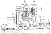
- FIG. 1 is a longitudinal sectional view showing a power transmission device according to a first embodiment of the present invention.
- Schematic diagram showing the concept of the power transmission device Enlarged view showing clutch means in the power transmission device Sectional view taken along line IV-IV in FIG.
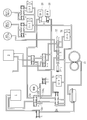
- the schematic diagram which shows the whole structure containing the transmission A in the power transmission device.
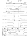
- Block diagram showing details of hydraulic control circuit in the power transmission device Control mode table of clutch control means in the same power transmission device Time chart in the same power transmission device Other time chart in the same power transmission device Flow chart showing control contents of engine control means in the power transmission device Flow chart showing control contents of clutch control means in the power transmission device
- the block diagram which shows the detail of the hydraulic control circuit in the power transmission device which concerns on the 2nd Embodiment of this invention.
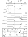
- Time chart in the same power transmission device The schematic diagram which shows the concept of the power transmission device which concerns on the 3rd Embodiment of this invention.
- the power transmission device is for transmitting or blocking driving force from an engine (driving source) of an automobile (vehicle) to a wheel (driving wheel), as shown in FIGS. 1 and 2.
- FIG. 1 is a longitudinal sectional view showing a main part of the power transmission device according to the present embodiment
- FIG. 2 is a schematic diagram (conceptual diagram) schematically showing the power transmission device according to the embodiment. It is.
- a torque converter 1 and a transmission 2 are disposed in the middle of a power transmission system from an engine E as a vehicle drive source to wheels (drive wheels D).
- the transmission 2 is provided with a transmission A.
- reference numeral 11 denotes an input shaft extending from the engine E
- reference numeral 9 denotes an output shaft 9 extending to the transmission A.
- the torque converter 1 has a torque amplifying function for amplifying torque from the engine E and transmitting the amplified torque to the transmission 2.
- the torque converter covers 1a, 13 containing (hydraulic oil) in a liquid-tight state the pump P formed on the torque converter cover 1a side and rotating together with the torque converter cover 1a And a turbine T that is rotatably arranged.
- the input shaft 11 is connected to the torque converter cover 13 via the cover member 12.
- the torque converter covers 13, 1a, and the pump P are rotated, the rotational torque is amplified to the turbine T side via the liquid (hydraulic oil). Being transmitted.
- the “drive transmission system of the torque converter” in the present invention refers to a drive transmission system formed by the torque converter cover 1a, the pump P, and the turbine T described above.
- reference numeral 10 indicates a mission case.
- the torque converter cover 13 is connected to a connecting member 14 via a damper mechanism 7 made of a coil spring, and the connecting member 14 is spline-fitted to the outer peripheral surface of the second drive shaft 6.
- the connecting member 14 is spline-fitted to the outer peripheral surface of the second drive shaft 6.
- the first drive shaft 5 can be rotated by the driving force of the engine E via the drive transmission system of the torque converter 1 and is connected to the first clutch means 3a. It can be directly rotated by the driving force of the engine E without going through the drive transmission system of the torque converter 1, and is connected to the second clutch means 3b.
- the first drive shaft 5 is a cylindrical member, and the second drive shaft 6 is rotatably disposed therein, and the rotation axes thereof are the same.
- the first drive shaft 5 and the second drive shaft 6 are formed concentrically.
- the first drive shaft 5 is rotatable on the outside of the second drive shaft 6, and the second drive shaft 6 is rotatable on the inside of the first drive shaft 5.
- the first drive shaft 5 and the second drive shaft 6 can be independently rotated by selective operation by the clutch means 3.
- the clutch means 3 is operable when the automobile (vehicle) moves forward, and transmits the driving force of the engine E (driving source) to the wheels (driving wheels D) via the driving transmission system of the torque converter 1.
- the first clutch means 3a that can be in the 1 power transmission state and the driving force of the engine E (drive source) can be transmitted to the wheels (drive wheels D) without going through the drive transmission system of the torque converter 1 to be in the second power transmission state. It has the 2nd clutch means 3b.
- the first clutch means 3a and the second clutch means 3b include a plurality of drive side clutch plates 3aa and 3ba and driven side clutch plates 3ba and 3bb which are slidable in the left-right direction in the figure. Is formed to form a multi-plate clutch.
- the driving-side clutch plate 3aa is formed on the interlocking member 15 that is connected to and interlocked with the first driving shaft 5, and the driven-side clutch plate 3ab is formed on the housing 17, and these Drive side clutch plates 3aa and driven side clutch plates 3ab are alternately stacked.
- the adjacent drive side clutch plate 3aa and driven side clutch plate 3ab can be pressed against or separated from each other.
- FIG. 5 shows a state where the first clutch means 3a is operated and the driving side clutch plate 3aa and the driven side clutch plate 3ab are in pressure contact with each other.
- a driving side clutch plate 3ba is formed on the interlocking member 16 that is connected to and interlocked with the second driving shaft 6, and a driven side clutch plate 3bb is formed on the housing 17, and these The driving side clutch plate 3ba and the driven side clutch plate 3bb are alternately stacked. As a result, the adjacent drive side clutch plate 3ba and driven side clutch plate 3bb can be pressed against or separated from each other.
- FIG. 6 shows a state in which the second clutch means 3b is operated and the driving side clutch plate 3ba and the driven side clutch plate 3bb are in pressure contact with each other.
- the term “separation” here means not only physical separation but also a state where the pressure contact is released, and the driving force is transmitted in the pressure contact state, and the transmission of the driving force is interrupted in the separation state. Is done.
- the clutch means 3 includes a first clutch means 3a, a second clutch means 3b, and 2 corresponding to the first clutch means 3a and the second clutch means 3b in the same housing 17.
- the first clutch means 3a or the second clutch means 3b can be optionally operated by controlling the oil pressure for operating the hydraulic pistons P1 and P2 while having two hydraulic pistons P1 and P2.
- the hydraulic piston P1 moves to the right in the figure against the urging force of the return spring 3c, and at its tip.
- the first clutch means 3a is pressed so that the driving side clutch plate 3aa and the driven side clutch plate 3ab are pressed against each other.
- the driving side clutch plate 3ba and the driven side clutch plate 3bb in the second clutch means 2b are formed with irregular shapes on the periphery thereof, and the tip of the hydraulic piston P1 is inserted in the concave portion. It is configured to be.
- reference numeral 21 in the figure denotes a stopper provided on the first clutch means 3a side and the second clutch means 3b side.
- the casing 17 constituting the clutch means 3 is connected to an interlocking member 18 on which a gear G1 is formed, and the gear G1 is configured to mesh with a gear G2 formed on the output shaft 9. Thereby, the driving force of the engine E transmitted by the first clutch means 3a or the second clutch means 3b reaches the interlocking member 18 via the housing 17 and is transmitted to the output shaft 9. .
- the oil pump 31 is operated by the driving force of the engine E to supply oil (hydraulic oil) to the clutch means 3 (first clutch means 3a and second clutch means 3b) and the torque converter 1 (described below, continuously variable). The same applies to the transmission 25), and the clutch means 3 and the torque converter 1 can be operated. That is, the oil pump 31 can discharge oil by using the driving force of the engine E so that it always operates when the engine E is driven and stops when the engine E is stopped. It has become.
- the clutch control means 4 selectively injects hydraulic pistons P1 and P2 by injecting hydraulic oil into the hydraulic chamber S1 or S2 at a predetermined pressure according to the state of the automobile (vehicle) (vehicle speed, vehicle body inclination angle, etc.).
- the first clutch means 3a or the second clutch means 3b is optionally operated by operating the engine E (drive wheel D) to drive the driving force of the engine E (drive source) via the drive transmission system of the torque converter 1. Can transmit the driving force of the engine E (drive source) to the wheels (drive wheels D) without passing through the drive transmission system of the torque converter 1 (second power transmission state). It is.
- the third clutch means 8 is composed of a multi-plate clutch, and transmits the driving force of the engine E (drive source) to the wheels (drive wheels D) via the drive transmission system of the torque converter 1 when the vehicle moves backward. belongs to. That is, when the shift lever of the vehicle is operated to set the R range (reverse), the idle gear is between the gear G3 formed on the interlocking member 15 and the gear G4 formed on the interlocking member 19 on the output shaft 9 side. (Not shown) intervenes and meshes so that the driving force of the engine E reaches the third clutch means 8.
- the third clutch means 8 has a housing 20 that is connected to and interlocked with the output shaft 9, and a hydraulic piston P3 is provided in the housing 20.
- the drive side clutch plates 8a and the driven side clutch plates 8b are alternately stacked.
- the drive side clutch plate 8a and the driven side clutch plate 8b can be pressed against or separated from each other by the operation of the hydraulic piston P3.
- the engine control means 22 automatically stops the engine E and idle-stops on the condition that the vehicle (vehicle) has become a predetermined vehicle speed or less (a vehicle speed between just before the stop and until the stop),
- the engine E can be started on condition that the brake operation is released or the accelerator is depressed in the idle stop state, and is formed in an ECU (not shown) for controlling the engine E, for example. That is, the ECU controls the overall control of the engine E, whereas the engine control means 22 controls the idle stop operation.
- the conditions for starting the engine E after the idle stop may be other conditions such as when the vehicle speed increases, or a combination of these various conditions.
- the first clutch means 3a or the second clutch means 3b is optionally operated according to the state of the vehicle, and the driving force of the engine E is transmitted to the wheels via the drive transmission system of the torque converter 1. Since the clutch control means 4 capable of transmitting the driving force of the engine E to the wheels (driving wheels D) without passing through the driving transmission system of the torque converter is provided, the power transmission device is complicated. In addition, it is possible to suppress the increase in size, improve the starting performance by the torque amplification function of the torque converter 1, and improve the power transmission efficiency during steady running. In addition, according to this embodiment, a lockup clutch can be made unnecessary.
- first drive shaft 5 and the second drive shaft 6 are formed concentrically, the first drive shaft 5 and the second drive shaft 6 are respectively extended (two are provided side by side)
- the whole power transmission device can be further reduced in size as compared with the above.
- the second drive shaft 6 is connected to the engine E via the damper mechanism 7 that can attenuate the torque fluctuation, the vibration of the engine E transmitted to the second clutch means 3b can be attenuated.
- the clutch means 3 has a first clutch means 3a, a second clutch means 3b, and two hydraulic pistons P1, P2 corresponding to the first clutch means 3a and the second clutch means 3b in the same housing 17.
- the first clutch means 3a or the second clutch means 3b can be optionally operated by controlling the hydraulic pressure for operating the hydraulic pistons P1 and P2, thereby further simplifying the entire power transmission device. And can be miniaturized.
- the transmission A in this embodiment is a continuously variable transmission (Continuously Variable Transmission: so-called CVT).
- CVT Continuous Variable Transmission
- the second clutch means 3b of the clutch means 3 and the wheels (drive) are in the middle of the power transmission system from the vehicle drive source (engine E) to the wheels (drive wheels D).
- the continuously variable transmission 25 is interposed between the wheel D) and the wheel D).
- the continuously variable transmission 25 has two pulleys Q1 and Q2 and a belt V suspended between them.
- the hydraulic control circuit 24 operates the movable sheaves of the pulleys Q1 and Q2 independently of each other.
- the diameter of the belt V suspension is changed to perform a desired speed change.
- the continuously variable transmission 25 is configured so that oil (operating oil) is supplied from the oil pump 31 and the movable sheaves of the pulleys (Q1, Q2) can be operated by the oil pressure of the oil.
- the continuously variable transmission 25 has clutch control means 4 electrically connected to a brake switch S1 of a brake pedal, a position sensor S2 of a shift lever, an engine control means 22 and the like in the vehicle. Control by the hydraulic control circuit 24 is performed by the clutch control means 4.
- symbol S3 indicates a throttle opening sensor of an accelerator pedal in the vehicle.
- the second clutch means 3b of the clutch means 3 serves as a clutch for moving the vehicle forward and a clutch for transmitting the driving force of the engine E to the driving wheels D without passing through the drive transmission system of the torque converter 1.
- the symbol F indicates a differential gear provided in the vehicle.
- Reference numeral S4 is an engine rotation sensor for detecting the rotation speed of the engine E
- S5 is a speed sensor for detecting the rotation speed of the first drive shaft 5
- S6 is the clutch means 3 (second clutch means 3b in this embodiment).
- S7 indicates a secondary shaft speed sensor
- S8 indicates a countershaft speed sensor.
- the hydraulic control circuit 24 mainly includes an oil passage and a valve for connecting the oil pump 31 and an oil supply target (torque converter 1, clutch means 3, etc.), and a solenoid for opening and closing the valve.
- reference numeral 26 denotes a regulator valve that regulates the line pressure
- reference numeral 27 denotes a linear solenoid (LSB) 27 that controls the control pressure of the regulator 26.
- Reference numeral 32 denotes a manual valve that switches the supply path in accordance with the transmission range (P, R, N, D)
- reference numeral 28 denotes a linear solenoid (LSA) that controls the clutch pressure.
- the linear solenoid (LSA) 28 controls the clutch pressure for the clutch means 3 in the D range, the RVS CLUTCH clutch pressure in the R range, and the line pressure at which the regulator valve regulates the pressure using the linear solenoid (LSB) 27. Can be controlled.
- the adjusting means 23 is connected in the middle of the oil flow path from the oil pump 31 to the torque converter 1.
- the adjusting means 23 supplies the oil to the torque converter 1 by the oil pump 31 when the fuel is cut (fuel supply is stopped) to the engine E in the deceleration process of the vehicle and the vehicle speed becomes a predetermined value or less.
- the amount can be limited, and the supply of oil to the clutch means 3 and the continuously variable transmission 25 can be prioritized.
- the adjusting means 23 includes a first supply path 23a that supplies oil to the torque converter 1 at a normal time, and a second supply path 23b in which an orifice 23ba is formed to limit the supply amount of the oil.
- the hydraulic valve mechanism includes a valve 23c that opens and closes the first supply path 23a by hydraulic pressure.
- the opening / closing operation of the valve 23 c is performed by a solenoid (SHA) 29 and a solenoid (SHB) 30.
- the adjusting means 23 according to the present embodiment is always urged in the direction in which the valve 23c is closed by the spring so that the first supply path 23a is closed.
- the adjustment means 23 is in a state where the fuel is cut with respect to the engine E in the deceleration process of the vehicle and the vehicle speed becomes a predetermined value or less.
- the supply amount is limited, the supply amount of the oil is prohibited and no oil is supplied to the torque converter 1, and the clutch means 3 (second clutch means 3b in this embodiment) and the continuously variable The oil supply to the transmission 25 may be prioritized.
- the clutch control means 4 can arbitrarily operate the hydraulic valve mechanism constituting the adjusting means 23 by controlling the solenoid (SHA) 29 and the solenoid (SHB) 30 according to the set mode. It is configured as follows. In the figure, the mark mark indicates that the solenoid is electrically turned on, the cross mark indicates that the solenoid is electrically turned off, and the “line pressure” indicates that the line pressure is directly input to the clutch means 3. “LSA” and “LSA” indicate that the linear solenoid valve (LSA) 28 controls the clutch pressure.
- FIG. 11 shows a time chart of control by the clutch control means 4 in the process of deceleration, stop and acceleration of the vehicle.
- the torque converter 1 by the oil pump 31 is used. It can be seen that the amount of oil supplied to the engine is limited, and oil supply to the clutch means 3 and the continuously variable transmission 25 is prioritized.
- the clutch control means 4 when the vehicle is defueled during the deceleration process of the vehicle and the vehicle speed becomes equal to or lower than a predetermined value (second vehicle speed Vb in the figure), the clutch control means 4 performs the second operation. Only the clutch means 3b is operated. When the vehicle speed further decreases to a predetermined value (first vehicle speed Va in the figure), the operation of the second clutch means 3b is stopped and the idle stop state is set. Thus, when the vehicle is defueled during the deceleration process of the vehicle and the vehicle speed becomes equal to or lower than a predetermined value (second vehicle speed Vb in the figure), the clutch control means 4 performs the second clutch means 3b. Therefore, the oil supply to the second clutch means 3b can be more reliably and smoothly performed than the oil supply to both the first clutch means 3a and the second clutch means 3b.
- the engine control means 22 performs an idle stop on the condition that the gear ratio of the continuously variable transmission 25 is equal to or greater than a predetermined value (a gear ratio required for starting the vehicle). ing. As a result, it is possible to appropriately ensure the starting driving force when starting the engine after the idle stop.
- the linear solenoid valve (LSB) 27 is controlled to increase the line pressure adjusted by the regulator valve 27. You may do it. Even in this case, it is preferable to control the regulator valve 27 so that the line pressure is returned to the normal value when the first vehicle speed Va is reached and the engine is in the idling stop state (see the line pressure setting item in the figure).
- the process proceeds to S9 to determine whether or not the engine is being started. If it is determined that the engine is being started, the process proceeds to S10 and whether or not the engine has been started. It is determined whether or not. If it is determined in S10 that the engine start is completed, the process proceeds to S11 to perform engine operation (engine drive). If it is determined that the engine start is not completed, the process proceeds to S4 and the engine is started. A start is made.
- the process proceeds to S12, and it is determined whether or not the ratio of the continuously variable transmission (automatic transmission 25) is equal to or greater than a predetermined value. If the ratio is greater than or equal to the predetermined value in S12, the process proceeds to S13 and whether or not the idle stop condition (various conditions such as vehicle speed is lower than the predetermined value, water temperature and oil temperature are higher than the predetermined value, no failure, etc.) is established. If the ratio is not equal to or greater than the predetermined value, the process proceeds to S11 to perform engine operation (engine drive). If it is determined in S13 that the idle stop condition is satisfied, the process proceeds to S14 to enter the idle stop state.
- the idle stop condition variable conditions such as vehicle speed is lower than the predetermined value, water temperature and oil temperature are higher than the predetermined value, no failure, etc.
- the control content of the clutch control means 4 in the above embodiment will be described based on the flowchart of FIG. First, it is determined whether or not the engine is idling stop (S1). If the engine is idling, the second clutch means 3b is turned off (S2), the first clutch means 3a is turned off (S3), and the torque converter 1 is turned on. The flow rate is turned off (S4). However, if it is determined in S1 that the engine is not idling, the process proceeds to S5 to determine whether or not the engine is being started. If the engine is being started, the process proceeds to S6 and a predetermined time has elapsed since the engine was started. It is determined whether or not.
- the process proceeds to S7, where it is determined whether or not the engine speed is equal to or greater than a predetermined value. If the engine speed is not equal to or greater than the predetermined value, the process proceeds to S8 and hydraulic pressure is determined. It is determined whether or not the switch S6 (detection means) is on. Further, when the hydraulic switch S6 (detection means) is not turned on, the routine proceeds to S9, where it is determined whether or not the clutch slip ratio is greater than or equal to a predetermined value. The means 3b is activated. After the second clutch means 3b is operated in S10, the process proceeds to S3 and S4.
- the process proceeds to S14 to determine whether or not the accelerator is off. If the accelerator is off, the process proceeds to S15 and whether or not the vehicle is decelerating. Is determined. If it is determined in S15 that the vehicle is decelerating, the process proceeds to S16 to determine whether or not the vehicle speed is lower than the predetermined (second speed Vb). If the vehicle speed is lower than the second speed Vb, the process proceeds to S17. Then, the second clutch means 3b is turned on to operate, the first clutch means 3a is turned off in S18, and the flow rate to the torque converter 1 is turned off in S19.
- the oil pump 31 supplies oil to the torque converter 1. Since the supply amount can be limited (or prohibited) and priority can be given to the oil supply to the clutch means 3 (second clutch means 3b in the present embodiment) and the continuously variable transmission 25, the torque converter 1 is provided, and It is applied to a vehicle that is idle-stopped, and can improve fuel efficiency without performing fuel cut recovery during the deceleration of the vehicle, and can reduce cost by eliminating the need for an electric oil pump.
- the adjusting means 23 includes a first supply path 23a for supplying oil to the torque converter 1 at a normal time, a second supply path 23b for limiting or prohibiting the supply amount of the oil, and the first supply path by hydraulic pressure. Since it comprises a hydraulic valve mechanism having a valve 23c that opens and closes 23a, it is possible to switch instantaneously and smoothly between the case where the oil supply to the torque converter 1 is restricted or prohibited and the case where the oil is not restricted or prohibited. .
- valve 23c is always urged by a spring in a direction to close the first supply path 23a, the fuel is cut into the engine during the deceleration of the vehicle, and the vehicle speed is set to a predetermined value ( When the second vehicle speed Vb) or less is reached, since the pump speed is low, even when the control pressure is reduced, the oil supply to the torque converter 1 is surely limited or prohibited regardless of the set operating pressure of the valve 23c. be able to.
- the power transmission device is for transmitting or blocking driving force from an engine (driving source) of an automobile (vehicle) to wheels (driving wheels).
- the torque converter 1, the clutch means 3, the oil pump 31, the clutch control means 4, the engine control means 22, the adjustment means 23, the first drive shaft 5, and the second drive It mainly includes a shaft 6, a damper mechanism 7, a third clutch means 8, and a transmission A (continuously variable transmission 25).
- symbol is attached
- the pressure accumulating means 33 is connected from the oil pump 31 to the middle of the oil circulation path of the clutch means 3.
- the pressure accumulating means 33 is composed of an accumulator capable of accumulating oil, and when the vehicle speed becomes a predetermined value (second vehicle speed Vb) or less when the fuel E is cut with respect to the engine E in the vehicle deceleration process.
- the oil accumulated in the pressure accumulating means 33 can be discharged and supplied to the clutch means 3 (particularly the second clutch means 3b in the present embodiment) and the continuously variable transmission 25.
- reference numeral 34 denotes a check valve.
- the timing of releasing the oil accumulated by the pressure accumulating means 33 is not limited to the time point when the vehicle speed becomes equal to or lower than the predetermined value (second vehicle speed Vb) as described above.
- the predetermined value second vehicle speed Vb
- the continuously variable transmission 25 is preferably controlled so that its speed ratio is kept constant, whereby the required pressure for accumulating can be reduced and the capacity of the accumulating means 33 can be reduced.
- the adjusting means 23 when starting the engine E after the idle stop, the adjusting means 23 is operated by controlling on / off of the solenoid (SHA) 29 and the solenoid (SHB) 30, and the oil pump 31 The amount of oil supplied to the torque converter 1 is limited, and oil supply to the clutch means 3 is prioritized.
- SHA solenoid
- SHB solenoid
- the pressure accumulating means 33 is connected in the middle of the oil flow path of the clutch means 3 from the oil pump 31 and is in a fuel cut state with respect to the engine E during the deceleration of the vehicle so that the vehicle speed is equal to or less than a predetermined value (second vehicle speed Vb). Any other form may be used as long as it can release the accumulated oil and supply it to the clutch means 3 and the continuously variable transmission 25.
- the power transmission device is for transmitting or interrupting the driving force from the engine (drive source) of the automobile (vehicle) to the wheels (drive wheels).
- the torque converter 1, the clutch means 3 ′, the oil pump 31, the clutch control means 4, the engine control means 22, the adjustment means 23, the damper mechanism 7, and the vehicle are operated when the vehicle is moving backward.
- the reverse clutch means 3′c and the transmission A are mainly included.
- symbol is attached
- the clutch means 3 ′ operates when the vehicle moves forward, and transmits the driving force of the engine E to the wheels via the drive transmission system of the torque converter 1 (can be in a first power transmission state).
- 3'a and a lock-up clutch means 3'b for transmitting the driving force of the engine E to the wheels without going through the drive transmission system of the torque converter 1 (which can be in the second power transmission state), and the clutch control means 4
- the forward clutch means 3′a and the lock-up clutch means 3′b can be optionally operated according to the state of the vehicle to enter the first power transmission state or the second power transmission state.
- the lock-up clutch means 3'b is formed of a lock-up clutch that is formed in the torque converter 1 and can be connected to the turbine T of the torque converter 1. In the connected state, the torque converter cover and the turbine Is configured to be directly connected via a clutch piston. According to the present embodiment, the present invention can be easily applied to a vehicle provided with a lock-up clutch means (lock-up clutch) that has been relatively popular.
- the power transmission device has been described above.
- the present invention is not limited to these, and the clutch means transmits the driving force of the engine E to the wheels via the drive transmission system of the torque converter 1. Any form may be used as long as it can be in the power transmission state or the second power transmission state in which the driving force of the engine E is transmitted to the wheels without going through the drive transmission system of the torque converter 1.
- the clutch means and continuously variable transmission are As long as it is a power transmission device provided with an adjusting means that can prioritize the supply of oil, it can also be applied to devices having different external shapes or to which other functions are added.
Landscapes
- Engineering & Computer Science (AREA)
- Mechanical Engineering (AREA)
- Chemical & Material Sciences (AREA)
- Combustion & Propulsion (AREA)
- General Engineering & Computer Science (AREA)
- Transportation (AREA)
- Automation & Control Theory (AREA)
- Control Of Transmission Device (AREA)
- Control Of Vehicle Engines Or Engines For Specific Uses (AREA)
- Control Of Fluid Gearings (AREA)
- Hybrid Electric Vehicles (AREA)
Abstract
Description
第1の実施形態に係る動力伝達装置は、自動車(車両)のエンジン(駆動源)による駆動力を車輪(駆動輪)に伝達又は遮断するためのものであり、図1及び図2に示すように、トルクコンバータ1と、クラッチ手段3と、オイルポンプ31と、クラッチ制御手段4と、エンジン制御手段22と、調整手段23と、第1駆動シャフト5と、第2駆動シャフト6と、ダンパ機構7と、第3クラッチ手段8と、変速機A(無段変速機25)とを主に有している。尚、図1は、本実施形態に係る動力伝達装置の主要部を表す縦断面図であり、図2は、同実施形態に係る動力伝達装置を模式化した模式図(概念図)を示すものである。
Variable Transmission :所謂CVT)から成るものとされている。具体的には、図8に示すように、車両の駆動源(エンジンE)から車輪(駆動輪D)に至る動力伝達系の途中であってクラッチ手段3の第2クラッチ手段3bと車輪(駆動輪D)との間において、無段変速機25を介装させたものとされる。
まず、イグニッションがオンしたか否かを判断し(S1)、イグニッションがオンの場合は、S2へ進んで、アイドルストップ中であるか否かを判定する。そして、アイドルストップ中であると判定されると、アクセルペダルの踏み込みがあるか否かが判定され(S3)、当該アクセルペダルの踏み込みがあると判定された場合、S4へ進んでエンジン始動がなされる。
まず、アイドルストップ中であるか否かが判定され(S1)、アイドルストップ中の場合、第2クラッチ手段3bをオフ(S2)、第1クラッチ手段3aをオフ(S3)、トルクコンバータ1への流量をオフ(S4)とする。然るに、S1にてアイドルストップ中でないと判定されると、S5へ進んでエンジン始動中であるか否かが判定され、エンジン始動中である場合は、S6へ進んでエンジン始動から所定時間経過しているか否かが判定される。
本実施形態に係る動力伝達装置は、第1の実施形態と同様、自動車(車両)のエンジン(駆動源)による駆動力を車輪(駆動輪)に伝達又は遮断するためのものであり、図1及び図2に示すように、トルクコンバータ1と、クラッチ手段3と、オイルポンプ31と、クラッチ制御手段4と、エンジン制御手段22と、調整手段23と、第1駆動シャフト5と、第2駆動シャフト6と、ダンパ機構7と、第3クラッチ手段8と、変速機A(無段変速機25)とを主に有している。尚、第1の実施形態と同様の構成要素には同一の符号を付し、それらの詳細な説明を省略する。
本実施形態に係る動力伝達装置は、第1、2の実施形態と同様、自動車(車両)のエンジン(駆動源)による駆動力を車輪(駆動輪)に伝達又は遮断するためのものであり、図17に示すように、トルクコンバータ1と、クラッチ手段3’と、オイルポンプ31と、クラッチ制御手段4と、エンジン制御手段22と、調整手段23と、ダンパ機構7と、車両の後進時に作動する後進クラッチ手段3’cと、変速機A(無段変速機25)とを主に有している。尚、第1、2の実施形態と同様の構成要素には同一の符号を付し、それらの詳細な説明を省略する。
2 変速機
3、3’ クラッチ手段
3a 第1クラッチ手段
3b 第2クラッチ手段
3’a 前進クラッチ手段
3’b ロックアップクラッチ手段
4 クラッチ制御手段
5 第1駆動シャフト
6 第2駆動シャフト
7 ダンパ機構
8 第3クラッチ手段
9 出力軸
10 ミッションケース
11 入力軸
12 カバー部材
13 トルコンカバー
14 連結部材
15、16 連動部材
17 筐体
18、19 連動部材
20 筐体
21 ストッパ
22 エンジン制御手段
23 調整手段
24 油圧制御回路
25 無段変速機
26 レギュレータバルブ
27、28 リニアソレノイドバルブ
29、30 ソレノイド
31 オイルポンプ
32 マニュアルバルブ
33 蓄圧手段
34 逆止弁
Claims (8)
- トルク増幅機能を有するトルクコンバータと、
前記トルクコンバータの駆動伝達系を介して前記エンジンの駆動力を前記車輪に伝達させる第1動力伝達状態、及び前記トルクコンバータの駆動伝達系を介さず前記エンジンの駆動力を前記車輪に伝達させる第2動力伝達状態とし得るクラッチ手段と、
前記エンジンの駆動力により作動して前記クラッチ手段及びトルクコンバータに対してオイルを供給し、当該クラッチ手段及びトルクコンバータを作動させ得るオイルポンプと、
前記オイルポンプからオイルが供給されて当該オイルの油圧によりプーリを作動させ、変速レシオを連続的に変更可能とされた無段変速機と、
車両の状態に応じて前記クラッチ手段を任意選択的に作動させて、前記第1動力伝達状態又は第2動力伝達状態とさせ得るクラッチ制御手段と、
車両が所定車速以下になったことを条件としてエンジンを自動的に停止させてアイドルストップさせるとともに、当該アイドルストップ状態でブレーキ操作を解除する又はアクセルを踏み込むことを条件としてエンジンを始動させ得るエンジン制御手段と、
を具備した動力伝達装置であって、
車両の減速過程で前記エンジンに対してフューエルカットした状態とされて車速が所定値以下となった際、前記オイルポンプによる前記トルクコンバータに対するオイルの供給量を制限又は禁止し、前記クラッチ手段及び無段変速機に対するオイルの供給を優先させ得る調整手段を備えたことを特徴とする動力伝達装置。 - 前記調整手段は、トルクコンバータに対して通常時オイルを供給する第1供給路と、当該オイルの供給量を制限又は禁止する第2供給路と、油圧により当該第1供給路を開閉させるバルブとを有した油圧バルブ機構から成ることを特徴とする請求項1記載の動力伝達装置。
- 前記バルブは、前記第1供給路を閉状態とする方向に常時付勢されたことを特徴とする請求項2記載の動力伝達装置。
- オイルを蓄圧可能な蓄圧手段を具備するとともに、車両の減速過程で前記エンジンに対してフューエルカットした状態とされて車速が所定値以下となった際、当該蓄圧手段で蓄圧されたオイルを放出して前記クラッチ手段及び無段変速機に供給し得るよう構成されたことを特徴とする請求項1~3の何れか1つに記載の動力伝達装置。
- 前記クラッチ手段は、車両の前進時に作動してトルクコンバータの駆動伝達系を介して前記エンジンの駆動力を前記車輪に伝達させる第1クラッチ手段、及び車両の前進時に作動して前記トルクコンバータの駆動伝達系を介さず前記エンジンの駆動力を前記車輪に伝達させる第2クラッチ手段を有するとともに、前記クラッチ制御手段は、車両の状態に応じて前記第1クラッチ手段及び第2クラッチ手段を任意選択的に作動させて、前記第1動力伝達状態又は第2動力伝達状態とさせ得るものとされ、且つ、車両の減速過程で前記エンジンに対してフューエルカットした状態とされて車速が所定値以下となった際、前記クラッチ制御手段が前記第2クラッチ手段のみを作動させることを特徴とする請求項1~4の何れか1つに記載の動力伝達装置。
- 前記トルクコンバータの駆動伝達系を介して前記エンジンの駆動力で回転可能とされ、前記第1クラッチ手段と連結された第1駆動シャフトと、
前記トルクコンバータの駆動伝達系を介さず前記エンジンの駆動力で回転可能とされ、前記第2クラッチ手段と連結された第2駆動シャフトと、
を具備し、前記第1駆動シャフトと第2駆動シャフトとは同心円状に形成されたことを特徴とする請求項5記載の動力伝達装置。 - 前記クラッチ手段は、車両の前進時に作動して前記トルクコンバータの駆動伝達系を介して前記エンジンの駆動力を前記車輪に伝達させる前進クラッチ手段、及び前記トルクコンバータの駆動伝達系を介さず前記エンジンの駆動力を前記車輪に伝達させるロックアップクラッチ手段を有するとともに、前記クラッチ制御手段は、車両の状態に応じて前記前進クラッチ手段及びロックアップクラッチ手段を任意選択的に作動させて、前記第1動力伝達状態又は第2動力伝達状態とさせ得ることを特徴とする請求項1~6の何れか1つに記載の動力伝達装置。
- 前記エンジン制御手段は、前記無段変速機の変速レシオが所定値以上となったことを条件としてアイドルストップさせることを特徴とする請求項1~7の何れか1つに記載の動力伝達装置。
Priority Applications (4)
| Application Number | Priority Date | Filing Date | Title |
|---|---|---|---|
| CN201080012060.5A CN102356254B (zh) | 2009-03-18 | 2010-03-17 | 动力传递装置 |
| DE112010001210.5T DE112010001210B4 (de) | 2009-03-18 | 2010-03-17 | Kraftübertragungsvorrichtung |
| US13/235,157 US8246511B2 (en) | 2009-03-18 | 2011-09-16 | Power transmitting apparatuses |
| US13/541,573 US8801573B2 (en) | 2009-03-18 | 2012-07-03 | Power transmitting apparatuses |
Applications Claiming Priority (2)
| Application Number | Priority Date | Filing Date | Title |
|---|---|---|---|
| JP2009066747A JP5398317B2 (ja) | 2009-03-18 | 2009-03-18 | 動力伝達装置 |
| JP2009-066747 | 2009-03-18 |
Related Child Applications (1)
| Application Number | Title | Priority Date | Filing Date |
|---|---|---|---|
| US13/235,157 Continuation US8246511B2 (en) | 2009-03-18 | 2011-09-16 | Power transmitting apparatuses |
Publications (1)
| Publication Number | Publication Date |
|---|---|
| WO2010107049A1 true WO2010107049A1 (ja) | 2010-09-23 |
Family
ID=42739709
Family Applications (1)
| Application Number | Title | Priority Date | Filing Date |
|---|---|---|---|
| PCT/JP2010/054513 Ceased WO2010107049A1 (ja) | 2009-03-18 | 2010-03-17 | 動力伝達装置 |
Country Status (5)
| Country | Link |
|---|---|
| US (2) | US8246511B2 (ja) |
| JP (1) | JP5398317B2 (ja) |
| CN (2) | CN104482194B (ja) |
| DE (1) | DE112010001210B4 (ja) |
| WO (1) | WO2010107049A1 (ja) |
Cited By (2)
| Publication number | Priority date | Publication date | Assignee | Title |
|---|---|---|---|---|
| CN103764977A (zh) * | 2011-08-31 | 2014-04-30 | 加特可株式会社 | 滑行停止车辆 |
| EP2762373A4 (en) * | 2011-09-29 | 2016-04-13 | Toyota Motor Co Ltd | HYDRAULIC TRANSMISSION CONTROL |
Families Citing this family (24)
| Publication number | Priority date | Publication date | Assignee | Title |
|---|---|---|---|---|
| JP5527873B2 (ja) | 2009-03-18 | 2014-06-25 | 株式会社エフ・シー・シー | 動力伝達装置 |
| JP5398317B2 (ja) | 2009-03-18 | 2014-01-29 | 株式会社エフ・シー・シー | 動力伝達装置 |
| JP5229395B2 (ja) * | 2009-09-28 | 2013-07-03 | トヨタ自動車株式会社 | 車両の制御装置 |
| US8668623B2 (en) * | 2009-10-15 | 2014-03-11 | Team Industries, Inc. | Engine braking primary clutch for CVT systems |
| CN103328790B (zh) | 2011-01-21 | 2016-04-20 | 丰田自动车株式会社 | 车辆控制装置 |
| DE102011087891B4 (de) * | 2011-12-07 | 2022-08-04 | Bayerische Motoren Werke Aktiengesellschaft | Automatisches Abschalten und Starten einer Brennkraftmaschine in einem Kraftfahrzeug |
| JP5742708B2 (ja) * | 2011-12-26 | 2015-07-01 | トヨタ自動車株式会社 | 油圧制御装置及び車両制御装置 |
| US9057351B2 (en) * | 2012-02-22 | 2015-06-16 | Ford Global Technologies, Llc | Method and system for engine control |
| US8989978B2 (en) * | 2012-03-06 | 2015-03-24 | Ford Global Technologies, Llc | Method for operating a vehicle powertrain |
| US8795119B2 (en) * | 2012-05-31 | 2014-08-05 | Gm Global Technology Operations, Llc | Latching clutch valve control system |
| US8855878B2 (en) * | 2012-08-09 | 2014-10-07 | Gm Global Technology Operations, Llc. | System and method for controlling an accumulator based on vehicle conditions |
| JP6147128B2 (ja) * | 2013-07-25 | 2017-06-14 | 株式会社エフ・シー・シー | 鞍乗り型車両 |
| JP6119690B2 (ja) | 2014-07-14 | 2017-04-26 | マツダ株式会社 | 自動変速機の制御装置 |
| JP6344373B2 (ja) * | 2015-12-07 | 2018-06-20 | マツダ株式会社 | 遠心振子ダンパ付きパワートレインの制御装置 |
| US10316962B2 (en) | 2016-01-18 | 2019-06-11 | Ford Global Technologies, Llc | Vehicle transmission with accumulator |
| US10011283B2 (en) * | 2016-06-28 | 2018-07-03 | Ford Global Technologies, Llc | System and method for driving vehicle accessories |
| US9810315B1 (en) | 2016-07-14 | 2017-11-07 | Ford Global Technologies, Llc | Vehicle and system of controlling a vehicle transmission |
| JP6556779B2 (ja) * | 2017-03-29 | 2019-08-07 | 本田技研工業株式会社 | 油圧回路装置及び油圧回路のライン圧昇圧方法 |
| CN109296723B (zh) * | 2017-07-24 | 2021-11-09 | 上海汽车集团股份有限公司 | 一种锁止离合器半接合点的自学习方法及装置 |
| JP6958410B2 (ja) | 2018-02-13 | 2021-11-02 | トヨタ自動車株式会社 | 車両の制御装置 |
| JP7000903B2 (ja) * | 2018-02-15 | 2022-01-19 | いすゞ自動車株式会社 | 動力伝達装置 |
| JP6823617B2 (ja) * | 2018-03-15 | 2021-02-03 | 本田技研工業株式会社 | 変速機の油圧制御装置及び油圧制御方法 |
| CN108357483A (zh) * | 2018-04-04 | 2018-08-03 | 徐工集团工程机械股份有限公司科技分公司 | 一种装载机智能动力切断系统及控制方法 |
| CN112026776B (zh) * | 2020-11-04 | 2021-03-30 | 盛瑞传动股份有限公司 | 车辆的断油换挡控制方法及装置、电子设备及存储介质 |
Citations (2)
| Publication number | Priority date | Publication date | Assignee | Title |
|---|---|---|---|---|
| JPS6424760U (ja) * | 1987-07-31 | 1989-02-10 | ||
| JP2005098392A (ja) * | 2003-09-25 | 2005-04-14 | Mitsubishi Motors Corp | トルクコンバータの油圧制御装置 |
Family Cites Families (23)
| Publication number | Priority date | Publication date | Assignee | Title |
|---|---|---|---|---|
| EP0304085B1 (en) * | 1987-08-21 | 1993-11-10 | Toyota Jidosha Kabushiki Kaisha | Hydraulic control device for belt-and-pulley type continuously variable transmission for a vehicle |
| JP2743379B2 (ja) * | 1988-05-06 | 1998-04-22 | 日産自動車株式会社 | 変速機の油圧制御装置 |
| US5417621A (en) * | 1993-12-22 | 1995-05-23 | Ford Motor Company | Driveaway lockup strategy for an infinitely variable tranmission with a hydrokinetic torque converter |
| JP3588673B2 (ja) * | 1999-05-20 | 2004-11-17 | 日産自動車株式会社 | アイドルストップ車両 |
| JP4659172B2 (ja) | 2000-04-03 | 2011-03-30 | トヨタ自動車株式会社 | 自動車用内燃機関制御装置 |
| JP3898879B2 (ja) | 2000-08-25 | 2007-03-28 | ジヤトコ株式会社 | 自動変速機の制御装置 |
| JP4278912B2 (ja) | 2001-11-28 | 2009-06-17 | ジヤトコ株式会社 | 自動変速機の変速油圧装置 |
| JP3743421B2 (ja) * | 2002-04-23 | 2006-02-08 | 日産自動車株式会社 | 車両の制御装置 |
| JP4126948B2 (ja) | 2002-04-25 | 2008-07-30 | トヨタ自動車株式会社 | 車両用内燃機関の停止制御装置 |
| JP3588091B2 (ja) * | 2002-08-22 | 2004-11-10 | 本田技研工業株式会社 | ハイブリッド車両の油圧制御装置 |
| JP3731746B2 (ja) * | 2002-09-26 | 2006-01-05 | 日産自動車株式会社 | エンジン及びベルト式無段変速機の制御装置 |
| JP2005003193A (ja) * | 2003-05-16 | 2005-01-06 | Toyota Motor Corp | 車両用ロックアップクラッチの制御装置 |
| JP2005036820A (ja) * | 2003-07-15 | 2005-02-10 | Nissan Motor Co Ltd | アイドルストップ車両の変速機油圧制御装置 |
| JP4129264B2 (ja) * | 2005-02-14 | 2008-08-06 | ジヤトコ株式会社 | 自動変速機の制御装置 |
| JP4358130B2 (ja) * | 2005-02-22 | 2009-11-04 | ジヤトコ株式会社 | 自動変速機の油圧制御装置 |
| JP2006348862A (ja) | 2005-06-16 | 2006-12-28 | Toyota Motor Corp | 内燃機関の始動装置 |
| US7524266B2 (en) * | 2005-09-30 | 2009-04-28 | Mazda Motor Corporation | Engine starting system for power train |
| KR20070119764A (ko) * | 2006-06-13 | 2007-12-21 | 현대자동차주식회사 | 하이브리드 차량의 무단변속기 라인압 생성 시스템 및 생성방법 |
| US7558666B2 (en) | 2007-02-19 | 2009-07-07 | Digonis Michael | Idle stop system |
| JP5051007B2 (ja) * | 2008-06-03 | 2012-10-17 | 日産自動車株式会社 | 車両駆動系のアイドルストップ解除時制御装置 |
| JP5398317B2 (ja) | 2009-03-18 | 2014-01-29 | 株式会社エフ・シー・シー | 動力伝達装置 |
| JP5039819B2 (ja) * | 2010-09-01 | 2012-10-03 | ジヤトコ株式会社 | コーストストップ車両及びコーストストップ方法 |
| JP2012117424A (ja) * | 2010-11-30 | 2012-06-21 | Jatco Ltd | 車両の制御装置 |
-
2009
- 2009-03-18 JP JP2009066747A patent/JP5398317B2/ja not_active Expired - Fee Related
-
2010
- 2010-03-17 CN CN201410662926.7A patent/CN104482194B/zh not_active Expired - Fee Related
- 2010-03-17 DE DE112010001210.5T patent/DE112010001210B4/de not_active Expired - Fee Related
- 2010-03-17 WO PCT/JP2010/054513 patent/WO2010107049A1/ja not_active Ceased
- 2010-03-17 CN CN201080012060.5A patent/CN102356254B/zh not_active Expired - Fee Related
-
2011
- 2011-09-16 US US13/235,157 patent/US8246511B2/en active Active
-
2012
- 2012-07-03 US US13/541,573 patent/US8801573B2/en active Active
Patent Citations (2)
| Publication number | Priority date | Publication date | Assignee | Title |
|---|---|---|---|---|
| JPS6424760U (ja) * | 1987-07-31 | 1989-02-10 | ||
| JP2005098392A (ja) * | 2003-09-25 | 2005-04-14 | Mitsubishi Motors Corp | トルクコンバータの油圧制御装置 |
Cited By (4)
| Publication number | Priority date | Publication date | Assignee | Title |
|---|---|---|---|---|
| CN103764977A (zh) * | 2011-08-31 | 2014-04-30 | 加特可株式会社 | 滑行停止车辆 |
| CN103764977B (zh) * | 2011-08-31 | 2016-10-05 | 加特可株式会社 | 滑行停止车辆 |
| EP2762373A4 (en) * | 2011-09-29 | 2016-04-13 | Toyota Motor Co Ltd | HYDRAULIC TRANSMISSION CONTROL |
| US9365205B2 (en) | 2011-09-29 | 2016-06-14 | Toyota Jidosha Kabushiki Kaisha | Hydraulic pressure control device for transmission |
Also Published As
| Publication number | Publication date |
|---|---|
| US20120065022A1 (en) | 2012-03-15 |
| DE112010001210T5 (de) | 2012-07-05 |
| CN104482194B (zh) | 2017-05-17 |
| CN102356254A (zh) | 2012-02-15 |
| US8801573B2 (en) | 2014-08-12 |
| CN102356254B (zh) | 2014-12-17 |
| CN104482194A (zh) | 2015-04-01 |
| JP2010216625A (ja) | 2010-09-30 |
| US20120270702A1 (en) | 2012-10-25 |
| DE112010001210B4 (de) | 2020-03-26 |
| JP5398317B2 (ja) | 2014-01-29 |
| US8246511B2 (en) | 2012-08-21 |
Similar Documents
| Publication | Publication Date | Title |
|---|---|---|
| JP5398317B2 (ja) | 動力伝達装置 | |
| JP5527873B2 (ja) | 動力伝達装置 | |
| EP1413804A2 (en) | Vehicular transmission | |
| JP5145185B2 (ja) | 動力伝達装置 | |
| JP6111077B2 (ja) | 動力伝達装置 | |
| JP4888371B2 (ja) | 自動変速機の制御装置および制御方法 | |
| JP5660733B2 (ja) | 動力伝達装置 | |
| JP4125524B2 (ja) | 自動変速機の変速油圧装置 | |
| WO2014148138A1 (ja) | 動力伝達装置 | |
| JP5232316B2 (ja) | 動力伝達装置 | |
| JP4319128B2 (ja) | 自動変速機の制御装置 | |
| JP6362749B2 (ja) | 動力伝達装置 | |
| JP6290343B2 (ja) | 動力伝達装置 | |
| US11067167B2 (en) | Control device and control method for lock-up clutch | |
| JP7377278B2 (ja) | 自動変速機のロックアップ制御装置及びロックアップ制御方法 | |
| JP6913258B2 (ja) | 無段変速機の制御装置および制御方法 | |
| JP3501594B2 (ja) | 自動変速機の制御装置 | |
| JP2023077582A (ja) | 油圧制御装置 | |
| JP2003254423A (ja) | 無段変速機の制御装置 | |
| JP2004239297A (ja) | 変速機の制御装置 |
Legal Events
| Date | Code | Title | Description |
|---|---|---|---|
| WWE | Wipo information: entry into national phase |
Ref document number: 201080012060.5 Country of ref document: CN |
|
| 121 | Ep: the epo has been informed by wipo that ep was designated in this application |
Ref document number: 10753541 Country of ref document: EP Kind code of ref document: A1 |
|
| WWE | Wipo information: entry into national phase |
Ref document number: 1120100012105 Country of ref document: DE Ref document number: 112010001210 Country of ref document: DE |
|
| WWE | Wipo information: entry into national phase |
Ref document number: 4063/KOLNP/2011 Country of ref document: IN |
|
| 122 | Ep: pct application non-entry in european phase |
Ref document number: 10753541 Country of ref document: EP Kind code of ref document: A1 |